KR20200086625A - Method and apparatus for data processing in wireless communication system - Google Patents
Method and apparatus for data processing in wireless communication system Download PDFInfo
- Publication number
- KR20200086625A KR20200086625A KR1020190176960A KR20190176960A KR20200086625A KR 20200086625 A KR20200086625 A KR 20200086625A KR 1020190176960 A KR1020190176960 A KR 1020190176960A KR 20190176960 A KR20190176960 A KR 20190176960A KR 20200086625 A KR20200086625 A KR 20200086625A
- Authority
- KR
- South Korea
- Prior art keywords
- data
- layer device
- rlc
- header
- pdcp
- Prior art date
Links
Images


Classifications
-
- H—ELECTRICITY
- H04—ELECTRIC COMMUNICATION TECHNIQUE
- H04W—WIRELESS COMMUNICATION NETWORKS
- H04W28/00—Network traffic management; Network resource management
- H04W28/02—Traffic management, e.g. flow control or congestion control
- H04W28/06—Optimizing the usage of the radio link, e.g. header compression, information sizing, discarding information
-
- H04W12/001—
-
- H—ELECTRICITY
- H04—ELECTRIC COMMUNICATION TECHNIQUE
- H04W—WIRELESS COMMUNICATION NETWORKS
- H04W12/00—Security arrangements; Authentication; Protecting privacy or anonymity
- H04W12/03—Protecting confidentiality, e.g. by encryption
Landscapes
- Engineering & Computer Science (AREA)
- Computer Networks & Wireless Communication (AREA)
- Signal Processing (AREA)
- Computer Security & Cryptography (AREA)
- Mobile Radio Communication Systems (AREA)
Abstract
Description
본 개시는 무선 통신 시스템에서 데이터 처리 방법 및 장치에 관한 것이다.The present disclosure relates to a method and apparatus for processing data in a wireless communication system.
4G 통신 시스템 상용화 이후 증가 추세에 있는 무선 데이터 트래픽 수요를 충족시키기 위해, 개선된 5G 통신 시스템 또는 pre-5G 통신 시스템을 개발하기 위한 노력이 이루어지고 있다. 이러한 이유로, 5G 통신 시스템 또는 pre-5G 통신 시스템은 4G 네트워크 이후 (Beyond 4G Network) 통신 시스템 또는 LTE 시스템 이후 (Post LTE) 이후의 시스템이라 불리어지고 있다. 3GPP에서 정한 5G 통신 시스템은 New Radio (NR) 시스템이라고 불리고 있다. 높은 데이터 전송률을 달성하기 위해, 5G 통신 시스템은 초고주파(mmWave) 대역 (예를 들어, 60기가(60GHz) 대역과 같은)에서의 구현이 고려되고 있다. 초고주파 대역에서의 전파의 경로손실 완화 및 전파의 전달 거리를 증가시키기 위해, 5G 통신 시스템에서는 빔포밍(beamforming), 거대 배열 다중 입출력(massive MIMO), 전차원 다중입출력(Full Dimensional MIMO: FD-MIMO), 어레이 안테나(array antenna), 아날로그 빔형성(analog beam-forming), 및 대규모 안테나 (large scale antenna) 기술들이 논의되었고, NR 시스템에 적용되었다. 또한 시스템의 네트워크 개선을 위해, 5G 통신 시스템에서는 진화된 소형 셀, 개선된 소형 셀 (advanced small cell), 클라우드 무선 액세스 네트워크 (cloud radio access network: cloud RAN), 초고밀도 네트워크 (ultra-dense network), 기기 간 통신 (Device to Device communication: D2D), 무선 백홀 (wireless backhaul), 이동 네트워크 (moving network), 협력 통신 (cooperative communication), CoMP (Coordinated Multi-Points), 및 수신 간섭제거 (interference cancellation) 등의 기술 개발이 이루어지고 있다. 이 밖에도, 5G 시스템에서는 진보된 코딩 변조(Advanced Coding Modulation: ACM) 방식인 FQAM (Hybrid FSK and QAM Modulation) 및 SWSC (Sliding Window Superposition Coding)과, 진보된 접속 기술인 FBMC(Filter Bank Multi Carrier), NOMA(non-orthogonal multiple access), 및 SCMA(sparse code multiple access) 등이 개발되고 있다.Efforts have been made to develop an improved 5G communication system or a pre-5G communication system to meet the increasing demand for wireless data traffic after commercialization of the 4G communication system. For this reason, a 5G communication system or a pre-5G communication system is called a 4G network (Beyond 4G Network) communication system or an LTE system (Post LTE) or later system. The 5G communication system established by 3GPP is called a New Radio (NR) system. To achieve high data rates, 5G communication systems are contemplated for implementation in the ultra-high frequency (mmWave) band (eg, 60 gigabit (60 GHz) band). In order to mitigate path loss of radio waves in the ultra-high frequency band and increase the transmission distance of radio waves, in 5G communication systems, beamforming, massive array multiple input/output (massive MIMO), full dimensional multiple input/output (FD-MIMO) ), array antenna, analog beam-forming, and large scale antenna techniques have been discussed and applied to NR systems. In addition, in order to improve the network of the system, in the 5G communication system, an evolved small cell, an advanced small cell, a cloud radio access network (cloud RAN), an ultra-dense network , Device to Device communication (D2D), wireless backhaul, mobile network, cooperative communication, CoMP (Coordinated Multi-Points), and interference cancellation Technology development is being made. In addition, in the 5G system, advanced coding modulation (Advanced Coding Modulation (ACM)) hybrid FSK and QAM Modulation (FQAM) and sliding window superposition coding (SWSC), advanced access technology FBMC (Filter Bank Multi Carrier), NOMA (non-orthogonal multiple access), and SCMA (sparse code multiple access) are being developed.
한편, 인터넷은 인간이 정보를 생성하고 소비하는 인간 중심의 연결 망에서, 사물 등 분산된 구성 요소들 간에 정보를 주고 받아 처리하는 사물인터넷(Internet of Things, 이하 IoT) 망으로 진화하고 있다. 클라우드 서버 등과의 연결을 통한 빅데이터(Big data) 처리 기술 등이 IoT 기술에 결합된 IoE (Internet of Everything) 기술도 대두되고 있다. IoT를 구현하기 위해서, 센싱 기술, 유무선 통신 및 네트워크 인프라, 서비스 인터페이스 기술, 및 보안 기술과 같은 기술 요소 들이 요구되어, 최근에는 사물간의 연결을 위한 센서 네트워크(sensor network), 사물 통신(Machine to Machine, M2M), MTC(Machine Type Communication)등의 기술이 연구되고 있다. IoT 환경에서는 연결된 사물들에서 생성된 데이터를 수집, 분석하여 인간의 삶에 새로운 가치를 창출하는 지능형 IT(Internet Technology) 서비스가 제공될 수 있다. IoT는 기존의 IT(iInformation Technology)기술과 다양한 산업 간의 융합 및 복합을 통하여 스마트홈, 스마트 빌딩, 스마트 시티, 스마트 카 혹은 커넥티드 카, 스마트 그리드, 헬스 케어, 스마트 가전, 첨단의료서비스 등의 분야에 응용될 수 있다.Meanwhile, the Internet is evolving from a human-centered connection network in which humans generate and consume information, to an Internet of Things (IoT) network that exchanges information between distributed components such as objects. Internet of Everything (IoE) technology, in which big data processing technology, etc. through connection to a cloud server, is combined with IoT technology is also emerging. In order to implement IoT, technical elements such as sensing technology, wired/wireless communication and network infrastructure, service interface technology, and security technology are required, and recently, a sensor network for connection between objects, a machine to machine (Machine to Machine) , M2M), MTC (Machine Type Communication) and other technologies are being studied. In the IoT environment, an intelligent IT (Internet Technology) service that collects and analyzes data generated from connected objects to create new values in human life may be provided. IoT is a field of smart home, smart building, smart city, smart car or connected car, smart grid, health care, smart home appliance, high-tech medical service through convergence and combination between existing IT (iInformation Technology) technology and various industries. It can be applied to.
이에, 5G 통신 시스템을 IoT 망에 적용하기 위한 다양한 시도들이 이루어지고 있다. 예를 들어, 센서 네트워크(sensor network), 사물 통신(Machine to Machine, M2M), MTC(Machine Type Communication)등의 5G 통신이 빔 포밍, MIMO, 및 어레이 안테나 등의 기법에 의해 구현되고 있는 것이다. 앞서 설명한 빅데이터 처리 기술로써 클라우드 무선 액세스 네트워크(cloud RAN)가 적용되는 것도 5G 기술과 IoT 기술 융합의 일 예라고 할 수 있을 것이다.Accordingly, various attempts have been made to apply a 5G communication system to an IoT network. For example, 5G communication such as a sensor network, a machine to machine (M2M), and a machine type communication (MTC) are implemented by techniques such as beamforming, MIMO, and array antenna. It may be said that the application of cloud radio access network (cloud RAN) as the big data processing technology described above is an example of 5G technology and IoT technology convergence.
상술한 것과 이동통신 시스템의 발전에 따라 다양한 서비스를 제공할 수 있게 됨으로써, 이러한 서비스들을 효과적으로 제공하기 위한 방안이 요구되고 있다.As it is possible to provide various services according to the above-mentioned and the development of a mobile communication system, a method for effectively providing these services is required.
개시된 실시예는 이동통신 시스템에서 서비스를 효과적으로 제공할 수 있는 장치 및 방법을 제공한다.The disclosed embodiment provides an apparatus and method capable of effectively providing a service in a mobile communication system.
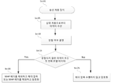
일 실시예에 따른 무선 통신 시스템에서 데이터 처리 방법은, 상위 계층 장치로부터 수신한 데이터가 상기 데이터를 수신한 계층 장치에서 처리 가능한 크기인지 여부를 판단하여 분할 여부를 결정하는 단계, 상기 데이터를 분할하기로 결정하는 경우, 데이터 분할을 수행하는 단계 및 분할된 첫 번째 데이터, 마지막 데이터 및 중간 데이터들을 구분하여 데이터 처리를 수행하는 단계를 포함한다.In a wireless communication system according to an embodiment, a data processing method may include determining whether data received from an upper layer device is a size that can be processed by a layer device receiving the data, and determining whether or not to divide the data. If it is determined to include the step of performing data division and the step of performing data processing by dividing the divided first data, last data, and intermediate data.
개시된 실시예에 따르면, 이동통신 시스템에서 서비스를 효과적으로 제공할 수 있다.According to the disclosed embodiment, it is possible to effectively provide a service in a mobile communication system.
도 1a는 일 실시예가 적용되는 LTE 시스템의 구조를 도시하는 도면이다.
도 1b는 일 실시예가 적용되는 LTE 시스템의 무선 프로토콜 구조를 나타낸 도면이다.
도 1c는 일 실시예가 적용되는 차세대 이동통신 시스템의 구조를 도시하는 도면이다.
도 1d는 일 실시예가 적용되는 차세대 이동통신 시스템의 무선 프로토콜 구조를 나타낸 도면이다.
도 1e는 일 실시예에 따른 단말과 네트워크의 연결을 설정하는 절차를 나타낸 도면이다.
도 1f는 일 실시예에 따른 기지국이 단말의 능력을 확인하기 위한 절차를 나타낸 도면이다.
도 1g는 일 실시예에 따른 상위 계층 데이터의 데이터 분할 방법 및 재조립 방법의 제1 실시예를 나타낸 도면이다.
도 1h은 일 실시예에 따른 상위 계층 데이터의 데이터 분할 방법 및 재조립 방법의 제1 실시예에 대한 구체적인 분할 및 재조립 방법을 나타낸 도면이다.
도 1i은 일 실시예에 따른 상위 계층 데이터의 데이터 분할 방법 및 재조립 방법의 제2 실시예에 대한 구체적인 분할 및 재조립 방법을 나타낸 도면이다.
도 1j는 일 실시예에 따른 상위 계층 헤더 압축 절차 또는 무결성 보호가 설정된 경우에 데이터를 처리하는 절차를 나타낸 도면이다.
도 1k는 제1 실시예 또는 제2 실시예를 PDCP 계층 장치의 위에 위치한 새로운 계층 장치에서 적용할 경우, 일 실시예에 따른 PDCP 계층 장치에서 효율적으로 데이터를 처리하는 제3 실시예를 나타낸 도면이다.
도 1l는 제1 실시예 또는 제2 실시예를 PDCP 계층 장치에서 적용하고, 일 실시예에 따른 분할 방법을 헤더 압축 절차 또는 무결성 보호 또는 암호화 절차 전에 수행하는 경우, PDCP 계층 장치에서 효율적으로 데이터를 처리하는 제4 실시예를 나타낸 도면이다.
도 1m는 제1 실시예 또는 제2 실시예를 PDCP 계층 장치에서 적용하고, 일 실시예에 따른 분할 방법을 헤더 압축 절차 후에 수행하며, 무결성 보호 또는 암호화 절차보다는 전에 수행하는 경우, PDCP 계층 장치에서 효율적으로 데이터를 처리하는 제 5 실시예를 나타낸 도면이다.
도 1n는 제1 실시예 또는 제2 실시예들를 PDCP 계층 장치에서 적용하고, 일 실시예에 따른 분할 방법을 헤더 압축 절차 또는 무결성 보호 또는 암호화 절차 후에 수행하는 경우, PDCP 계층 장치에서 효율적으로 데이터를 처리하는 제6 실시 예를 나타낸 도면이다.
도 1o은 일 실시예에 따른 상위 계층 데이터의 데이터 분할 방법 및 재조립 예에 대한 단말의 송신단의 동작을 나타낸 도면이다.
도 1p은 일 실시예에 따른 상위 계층 데이터의 데이터 분할 방법 및 재조립 예에 대한 단말의 수신단의 동작을 나타낸 도면이다.
도 1q에 일 실시예에 따른 단말 또는 무선 노드의 구성을 나타내는 블럭도이다.
도 1r는 일 실시예에 따른 무선 통신 시스템에서 TRP 장치 또는 무선 노드의 구성을 나타내는 블럭도이다.
도 2a는 일 실시예가 적용되는 LTE 시스템의 구조를 도시하는 도면이다.
도 2b는 일 실시예가 적용되는 LTE 시스템의 무선 프로토콜 구조를 나타낸 도면이다.
도 2c는 일 실시예가 적용되는 차세대 이동통신 시스템의 구조를 도시하는 도면이다.
도 2d는 일 실시예가 적용되는 차세대 이동통신 시스템의 무선 프로토콜 구조를 나타낸 도면이다.
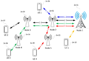
도 2e는 일 실시예에 따른 차세대 이동 통신 시스템에서 고려하는 무선 백홀을 지원하는 네트워크 구조를 나타낸 도면이다.
도 2f는 일 실시예에 따른 차세대 이동 통신 시스템의 무선 백홀 네트워크(IAB)에서 단말이 무선 노드(IAB node 또는 IAB donor)와 연결을 설정할 때 또는 자식 무선 노드가 부모 무선 노드(IAB node 또는 IAB donor)와 연결을 설정할 때 RRC 연결 설정을 수행하는 절차를 나타낸 도면이다.
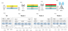
도 2g는 일 실시예에 따른 무선 백홀을 지원하는 차세대 이동 통신 시스템에서 각 무선 노드들이 가질 수 있는 프로토콜 계층 장치를 나타낸 도면이다.
도 2ha는 일 실시예에 따른 무선 백홀 지원 차세대 이동통신 시스템에서 무선 노드들의 베어러 관리 및 처리 방법을 나타낸 도면이다.
도 2hb는 본 개시의 일 실시예에 따른 무선 백홀 네트워크(IAB, Integrated Access Backhaul) 환경에서 데이터의 종류에 따라 서로 다른 데이터를 서로 다르게 처리하고 또는 서로 다른 프로토콜 계층 장치로 데이터를 처리하여 송신 또는 수신 또는 전달하는 절차를 나타낸 도면이며, 도 2ha을 더 구체화한 도면이다.
도 2i는 일 실시예에 따른 무선 링크 또는 무선 구간(예를 들면, 무선 백홀 네트워크에서 단말과 무선 노드 간 또는 단말과 최상위 노드 간 또는 단말이 접속한 무선 노드와 최상위 무선 노드 간 무선 링크)에서 보안을 강화할 수 있는 방법을 나타낸 도면이다.
도 2j는 도 2g에서 설명한 일 실시예에 따른 무선 백홀 네트워크 구조에서 무선 구간의 F1 인터페이스의 보안 강화를 위해서 별도의 상위 계층 장치(예를 들면, 제2의 PDCP 계층 장치)를 설정하고 무결성 보호 및 검증 절차를 수행하는 제2-1 실시예를 구체적으로 설명하는 도면이다.
도 2k는 도 2g에서 설명한 일 실시예에 따른 무선 백홀 네트워크 구조에서 무선 구간의 F1 인터페이스의 보안 강화를 위해서 별도의 상위 계층 장치(예를 들면, 제2의 PDCP 계층 장치)를 설정하고 암호화 및 복호화 절차를 수행하는 제2-2 실시예를 구체적으로 설명하는 도면이다.
도 2l은 일 실시예에 따른 무선 노드(최상위 무선 노드 또는 중간 노드 또는 단말)의 동작을 나타낸 도면이다.
도 2m에 일 실시예에 따른 단말 또는 무선 노드의 구조를 도시하였다.
도 2n는 일 실시예에 따른 무선 통신 시스템에서 TRP 장치 또는 무선 노드의 구성을 나타내는 블럭도이다.1A is a diagram showing the structure of an LTE system to which an embodiment is applied.
1B is a diagram illustrating a radio protocol structure of an LTE system to which an embodiment is applied.
1C is a diagram showing the structure of a next-generation mobile communication system to which an embodiment is applied.
1D is a diagram illustrating a radio protocol structure of a next-generation mobile communication system to which an embodiment is applied.
1E is a diagram illustrating a procedure for establishing a connection between a terminal and a network according to an embodiment.
1F is a diagram illustrating a procedure for a base station to check a terminal's capability according to an embodiment.
1G is a diagram illustrating a first embodiment of a data division method and a reassembly method of upper layer data according to an embodiment.
1H is a diagram illustrating a specific partitioning and reassembly method for a first embodiment of a data division method and a reassembly method of upper layer data according to an embodiment.
FIG. 1I is a diagram illustrating a specific division and reassembly method for a second embodiment of a data division method and a reassembly method of upper layer data according to an embodiment.
1J is a diagram illustrating a procedure for processing data when an upper layer header compression procedure or integrity protection is set according to an embodiment.
1K is a diagram illustrating a third embodiment of efficiently processing data in a PDCP layer device according to an embodiment when the first embodiment or the second embodiment is applied to a new layer device located above the PDCP layer device. .
FIG. 1L shows that when the first embodiment or the second embodiment is applied to the PDCP layer device, and the partitioning method according to an embodiment is performed before the header compression procedure or the integrity protection or encryption procedure, the PDCP layer device efficiently processes data. It is a figure showing the fourth embodiment to be processed.
FIG. 1M is a PDCP layer device in which the first embodiment or the second embodiment is applied in a PDCP layer device, and a partitioning method according to an embodiment is performed after a header compression procedure and before an integrity protection or encryption procedure. It is a figure showing a fifth embodiment for efficiently processing data.
FIG. 1N shows that when the first embodiment or the second embodiments are applied in a PDCP layer device, and a partitioning method according to an embodiment is performed after a header compression procedure or an integrity protection or encryption procedure, data from the PDCP layer device is efficiently performed. It is a figure showing the sixth embodiment to be processed.
1O is a diagram illustrating an operation of a transmitting end of a terminal for a data division method and a reassembly example of upper layer data according to an embodiment.
1P is a diagram illustrating an operation of a receiving end of a terminal for a data division method and a reassembly example of upper layer data according to an embodiment.
1Q is a block diagram showing the configuration of a terminal or a wireless node according to an embodiment.
1R is a block diagram showing the configuration of a TRP device or a wireless node in a wireless communication system according to an embodiment.
2A is a diagram showing the structure of an LTE system to which an embodiment is applied.
2B is a diagram illustrating a radio protocol structure of an LTE system to which an embodiment is applied.
2C is a diagram illustrating the structure of a next-generation mobile communication system to which an embodiment is applied.
2D is a diagram showing a radio protocol structure of a next-generation mobile communication system to which an embodiment is applied.
2E is a diagram illustrating a network structure supporting wireless backhaul considered in a next generation mobile communication system according to an embodiment.
Figure 2f is a terminal in a wireless backhaul network (IAB) of a next-generation mobile communication system according to an embodiment when a terminal establishes a connection with a wireless node (IAB node or IAB donor) or a child wireless node is a parent wireless node (IAB node or IAB donor) ) And shows the procedure for performing RRC connection establishment when establishing a connection.
2G is a diagram illustrating a protocol layer device that each wireless node may have in a next generation mobile communication system supporting wireless backhaul according to an embodiment.
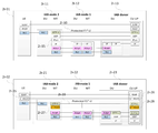
2ha is a diagram illustrating a bearer management and processing method of wireless nodes in a next generation mobile communication system supporting wireless backhaul according to an embodiment.
FIG. 2HB processes different data differently according to data types in a wireless backhaul network (IAB) environment according to an embodiment of the present disclosure, or transmits or receives data by processing data with different protocol layer devices. Or it is a diagram showing the delivery procedure, and is a diagram further embodying FIG. 2ha.
2i is a security in a wireless link or a wireless section (eg, a wireless link between a terminal and a wireless node in a wireless backhaul network or between a terminal and a top-level node or a wireless node and a top-level wireless node accessed by the terminal) according to an embodiment. It is a diagram showing how to strengthen the.
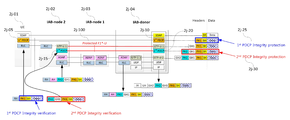
FIG. 2J sets a separate upper layer device (for example, a second PDCP layer device) for integrity enhancement of the F1 interface in the wireless section in the wireless backhaul network structure according to the embodiment described in FIG. 2G and protects integrity and It is a figure for specifically describing a 2-1 embodiment for performing a verification procedure.
FIG. 2K illustrates a separate upper layer device (for example, a second PDCP layer device) for encryption and decryption for security enhancement of an F1 interface in a wireless section in a wireless backhaul network structure according to the embodiment described with reference to FIG. 2G. It is a figure specifically explaining the 2-2 embodiment for performing the procedure.
FIG. 2L is a diagram illustrating the operation of a wireless node (the highest-level wireless node or an intermediate node or terminal) according to an embodiment.
2M shows the structure of a terminal or a wireless node according to an embodiment.
2N is a block diagram showing the configuration of a TRP device or a wireless node in a wireless communication system according to an embodiment.
이하 본 개시의 실시예를 첨부된 도면을 참조하여 상세하게 설명한다. 실시예를 설명함에 있어서 본 개시가 속하는 기술 분야에 익히 알려져 있고 본 개시와 직접적으로 관련이 없는 기술 내용에 대해서는 설명을 생략한다. 이는 불필요한 설명을 생략함으로써 본 개시의 요지를 흐리지 않고 더욱 명확히 전달하기 위함이다.Hereinafter, embodiments of the present disclosure will be described in detail with reference to the accompanying drawings. In describing the embodiments, descriptions of technical contents well known in the technical field to which the present disclosure pertains and which are not directly related to the present disclosure will be omitted. This is to more clearly communicate the gist of the present disclosure by omitting unnecessary descriptions.
마찬가지 이유로 첨부된 도면에 있어서 일부 구성요소는 과장되거나 생략되거나 개략적으로 도시되었다. 또한, 각 구성요소의 크기는 실제 크기를 전적으로 반영하는 것이 아니다. 각 도면에서 동일한 또는 대응하는 구성 요소에는 동일한 참조 번호를 부여하였다.For the same reason, in the accompanying drawings, some components are exaggerated, omitted, or schematically illustrated. Also, the size of each component does not entirely reflect the actual size. The same reference numbers are assigned to the same or corresponding elements in each drawing.
본 개시의 이점 및 특징, 그리고 그것들을 달성하는 방법은 첨부되는 도면과 함께 상세하게 후술되어 있는 실시예들을 참조하면 명확해질 것이다. 그러나 본 개시는 이하에서 개시되는 실시예들에 한정되는 것이 아니라 서로 다른 다양한 형태로 구현될 수 있으며, 단지 본 실시예들은 본 개시의 개시가 완전하도록 하고, 본 개시가 속하는 기술분야에서 통상의 지식을 가진 자에게 발명의 범주를 완전하게 알려주기 위해 제공되는 것이며, 본 개시는 청구항의 범주에 의해 정의될 뿐이다. 명세서 전체에 걸쳐 동일 참조 부호는 동일 구성 요소를 지칭한다.Advantages and features of the present disclosure, and a method of achieving them will be apparent with reference to embodiments described below in detail together with the accompanying drawings. However, the present disclosure is not limited to the embodiments disclosed below, and may be implemented in various different forms, and only the embodiments allow the disclosure of the present disclosure to be complete, and common knowledge in the art to which the present disclosure pertains. It is provided to fully inform the person having the scope of the invention, and the present disclosure is only defined by the scope of the claims. The same reference numerals refer to the same components throughout the specification.
이때, 처리 흐름도 도면들의 각 블록과 흐름도 도면들의 조합들은 컴퓨터 프로그램 인스트럭션들에 의해 수행될 수 있음을 이해할 수 있을 것이다. 이들 컴퓨터 프로그램 인스트럭션들은 범용 컴퓨터, 특수용 컴퓨터 또는 기타 프로그램 가능한 데이터 프로세싱 장비의 프로세서에 탑재될 수 있으므로, 컴퓨터 또는 기타 프로그램 가능한 데이터 프로세싱 장비의 프로세서를 통해 수행되는 그 인스트럭션들이 흐름도 블록(들)에서 설명된 기능들을 수행하는 수단을 생성하게 된다. 이들 컴퓨터 프로그램 인스트럭션들은 특정 방식으로 기능을 구현하기 위해 컴퓨터 또는 기타 프로그램 가능한 데이터 프로세싱 장비를 지향할 수 있는 컴퓨터 이용 가능 또는 컴퓨터 판독 가능 메모리에 저장되는 것도 가능하므로, 그 컴퓨터 이용가능 또는 컴퓨터 판독 가능 메모리에 저장된 인스트럭션들은 흐름도 블록(들)에서 설명된 기능을 수행하는 인스트럭션 수단을 내포하는 제조 품목을 생산하는 것도 가능하다. 컴퓨터 프로그램 인스트럭션들은 컴퓨터 또는 기타 프로그램 가능한 데이터 프로세싱 장비 상에 탑재되는 것도 가능하므로, 컴퓨터 또는 기타 프로그램 가능한 데이터 프로세싱 장비 상에서 일련의 동작 단계들이 수행되어 컴퓨터로 실행되는 프로세스를 생성해서 컴퓨터 또는 기타 프로그램 가능한 데이터 프로세싱 장비를 수행하는 인스트럭션들은 흐름도 블록(들)에서 설명된 기능들을 실행하기 위한 단계들을 제공하는 것도 가능하다.At this time, it will be understood that each block of the process flow chart diagrams and combinations of flow chart diagrams can be performed by computer program instructions. These computer program instructions may be mounted on a processor of a general purpose computer, special purpose computer, or other programmable data processing equipment, so that instructions performed through a processor of a computer or other programmable data processing equipment are described in flowchart block(s). It creates a means to perform functions. These computer program instructions can also be stored in computer readable or computer readable memory that can be oriented to a computer or other programmable data processing equipment to implement a function in a particular way, so that computer readable or computer readable memory It is also possible for the instructions stored in to produce an article of manufacture containing instructions means for performing the functions described in the flowchart block(s). Computer program instructions can also be mounted on a computer or other programmable data processing equipment, so a series of operational steps are performed on a computer or other programmable data processing equipment to create a process that is executed by the computer to generate a computer or other programmable data. It is also possible for instructions to perform processing equipment to provide steps for executing the functions described in the flowchart block(s).
또한, 각 블록은 특정된 논리적 기능(들)을 실행하기 위한 하나 이상의 실행 가능한 인스트럭션들을 포함하는 모듈, 세그먼트 또는 코드의 일부를 나타낼 수 있다. 또, 몇 가지 대체 실행 예들에서는 블록들에서 언급된 기능들이 순서를 벗어나서 발생하는 것도 가능함을 주목해야 한다. 예컨대, 잇달아 도시되어 있는 두 개의 블록들은 사실 실질적으로 동시에 수행되는 것도 가능하고 또는 그 블록들이 때때로 해당하는 기능에 따라 역순으로 수행되는 것도 가능하다.Also, each block may represent a module, segment, or portion of code that includes one or more executable instructions for executing the specified logical function(s). It should also be noted that in some alternative implementations, it is also possible that the functions mentioned in the blocks occur out of sequence. For example, two blocks shown in succession may in fact be executed substantially simultaneously, or it is also possible that the blocks are sometimes executed in reverse order according to a corresponding function.
이때, 본 실시예에서 사용되는 '~부'라는 용어는 소프트웨어 또는 FPGA(Field Programmable Gate Array) 또는 ASIC(Application Specific Integrated Circuit)과 같은 하드웨어 구성요소를 의미하며, '~부'는 어떤 역할들을 수행한다. 그렇지만 '~부'는 소프트웨어 또는 하드웨어에 한정되는 의미는 아니다. '~부'는 어드레싱할 수 있는 저장 매체에 있도록 구성될 수도 있고 하나 또는 그 이상의 프로세서들을 재생시키도록 구성될 수도 있다. 따라서, 일 예로서 '~부'는 소프트웨어 구성요소들, 객체지향 소프트웨어 구성요소들, 클래스 구성요소들 및 태스크 구성요소들과 같은 구성요소들과, 프로세스들, 함수들, 속성들, 프로시저들, 서브루틴들, 프로그램 코드의 세그먼트들, 드라이버들, 펌웨어, 마이크로코드, 회로, 데이터, 데이터베이스, 데이터 구조들, 테이블들, 어레이들, 및 변수들을 포함한다. 구성요소들과 '~부'들 안에서 제공되는 기능은 더 작은 수의 구성요소들 및 '~부'들로 결합되거나 추가적인 구성요소들과 '~부'들로 더 분리될 수 있다. 뿐만 아니라, 구성요소들 및 '~부'들은 디바이스 또는 보안 멀티미디어카드 내의 하나 또는 그 이상의 CPU들을 재생시키도록 구현될 수도 있다. 또한 실시예에서 '~부'는 하나 이상의 프로세서를 포함할 수 있다.At this time, the term'~ unit' used in this embodiment means software or hardware components such as a field programmable gate array (FPGA) or an application specific integrated circuit (ASIC), and'~ unit' performs certain roles. do. However,'~bu' is not limited to software or hardware. The'~ unit' may be configured to be in an addressable storage medium or may be configured to reproduce one or more processors. Thus, as an example,'~ unit' refers to components such as software components, object-oriented software components, class components, and task components, processes, functions, attributes, and procedures. , Subroutines, segments of program code, drivers, firmware, microcode, circuitry, data, database, data structures, tables, arrays, and variables. The functions provided within components and'~units' may be combined into a smaller number of components and'~units', or further separated into additional components and'~units'. In addition, the components and'~ unit' may be implemented to play one or more CPUs in the device or secure multimedia card. Also, in the embodiment,'~ unit' may include one or more processors.
이하 설명에서 사용되는 접속 노드(node)를 식별하기 위한 용어, 망 객체(network entity)들을 지칭하는 용어, 메시지들을 지칭하는 용어, 망 객체들 간 인터페이스를 지칭하는 용어, 다양한 식별 정보들을 지칭하는 용어 등은 설명의 편의를 위해 예시된 것이다. 따라서, 본 개시가 후술되는 용어들에 한정되는 것은 아니며, 동등한 기술적 의미를 가지는 대상을 지칭하는 다른 용어가 사용될 수 있다.Terms used to identify a connection node used in the following description, terms referring to network objects, terms referring to messages, terms referring to interfaces between network objects, terms referring to various identification information Etc. are exemplified for convenience of explanation. Therefore, the present disclosure is not limited to the terms described below, and other terms indicating objects having equivalent technical meanings may be used.
이하 설명의 편의를 위하여, 본 개시는 3GPP LTE(3rd Generation Partnership Project Long Term Evolution) 규격에서 정의하고 있는 용어 및 명칭들, 혹은 이를 기반으로 변형한 용어 및 명칭들을 사용한다. 하지만, 본 개시가 상술된 용어 및 명칭들에 의해 한정되는 것은 아니며, 다른 규격에 따르는 시스템에도 동일하게 적용될 수 있다. 본 개시에서 eNB는 설명의 편의를 위하여 gNB와 혼용되어 사용될 수 있다. 즉 eNB로 설명한 기지국은 gNB를 나타낼 수 있다. 본 개시에서, 단말이라는 용어는 핸드폰, NB-IoT 기기들, 센서들 뿐만 아니라 다양한 무선 통신 기기들을 나타낼 수 있다. For convenience of description below, the present disclosure uses terms and names defined in 3GPP LTE (3rd Generation Partnership Project Long Term Evolution) standard, or terms and names modified based on the terms. However, the present disclosure is not limited by the terms and names described above, and may be equally applied to systems conforming to other standards. In the present disclosure, the eNB may be used interchangeably with the gNB for convenience of explanation. That is, a base station described as an eNB may indicate gNB. In the present disclosure, the term terminal may refer to various wireless communication devices as well as mobile phones, NB-IoT devices, and sensors.
차세대 이동 통신 시스템에서는 기지국이 빔 기반으로 단말에게 서비스를 제공할 수 있으며, 많은 기능들을 지원하기 때문에 단말에게 이를 설정해주는 빔 관련 설정 정보 뿐만 아니라 많은 기능들에 대한 설정 정보를 포함하는 RRC 메시지의 크기가 굉장히 커질 수 있다. 또한 차세대 이동 통신 시스템은 다양한 서비스를 제공하고 높은 데이터 전송률을 서비스해야 하기 때문에 굉장히 큰 데이터들의 처리 절차를 지원해야 한다. In a next-generation mobile communication system, since a base station can provide a service to a terminal based on a beam, and supports a number of functions, the size of an RRC message including setting information for many functions as well as beam-related setting information for setting it to the terminal. Can be very large. In addition, the next generation mobile communication system needs to support various data processing procedures because it needs to provide various services and service high data rates.
PDCP 계층 장치에서는 상위 계층으로부터 수신하는 데이터에 대해 처리할 수 있는 최대 크기가 정해져 있다. 예를 들면 차세대 이동 통신 시스템에서 PDCP 계층 장치는 하나의 데이터에 대해 최대 9 킬로 바이트 크기까지 지원할 수 있다. 따라서 예를 들어 RRC 계층으로부터 수신하는 RRC 메시지 또는 TCP/IP 또는 UDP 계층 등 상위 계층으로부터 수신하는 사용자 계층 데이터의 크기가 PDCP 계층 장치가 지원하는 최대 크기(예를 들면 9킬로바이트)를 보다 크다면 PDCP 계층 장치는 해당 데이터를 처리할 수 없다.In the PDCP layer device, a maximum size that can be processed for data received from an upper layer is determined. For example, in a next-generation mobile communication system, a PDCP layer device can support up to 9 kilobytes in size for one data. Therefore, for example, if the size of user layer data received from a higher layer, such as an RRC message received from an RRC layer or a TCP/IP or UDP layer, is larger than the maximum size supported by the PDCP layer device (for example, 9 kilobytes), PDCP The layer device cannot process the data.
도 1a는 일 실시예가 적용되는 LTE 시스템의 구조를 도시하는 도면이다. 1A is a diagram showing the structure of an LTE system to which an embodiment is applied.
도 1a를 참조하면, LTE 시스템의 무선 액세스 네트워크는 차세대 기지국(Evolved Node B, 이하 ENB, Node B 또는 기지국)(1a-05, 1a-10, 1a-15, 1a-20), MME(1a-25, Mobility Management Entity) 및 S-GW(1a-30, Serving-Gateway)로 구성될 수 있다. 사용자 단말(User Equipment, 이하 UE 또는 단말)(1a-35)은 ENB(1a-05 ~ 1a-20) 및 S-GW(1a-30)를 통해 외부 네트워크에 접속할 수 있다.Referring to Figure 1a, the radio access network of the LTE system is the next generation base station (Evolved Node B, hereinafter ENB, Node B or base station) (1a-05, 1a-10, 1a-15, 1a-20), MME (1a- 25, Mobility Management Entity) and S-GW (1a-30, Serving-Gateway). User equipment (hereinafter referred to as UE or UE) 1a-35 may access an external network through
도 1a에서, ENB(1a-05 ~ 1a-20)는 UMTS(Universal Mobile Telecommunication System) 시스템의 노드 B에 대응될 수 있다. ENB는 UE(1a-35)와 무선 채널로 연결되며 노드 B 보다 복잡한 역할을 수행한다. LTE 시스템에서는 인터넷 프로토콜을 통한 VoIP(Voice over IP)와 같은 실시간 서비스를 비롯한 모든 사용자 트래픽이 공용 채널(shared channel)을 통해 서비스 되므로, UE들의 버퍼 상태, 가용 전송 전력 상태, 채널 상태 등의 상태 정보를 취합해서 스케줄링을 하는 장치가 필요하며, 이를 ENB(1a-05 ~ 1a-20)가 담당할 수 있다. 하나의 ENB는 통상 다수의 셀들을 제어할 수 있다. 예컨대, 100 Mbps의 전송 속도를 구현하기 위해서 LTE 시스템은 예컨대, 20 MHz 대역폭에서 직교 주파수 분할 다중 방식(Orthogonal Frequency Division Multiplexing, 이하 OFDM이라 한다)을 무선 접속 기술로 사용할 수 있다. 또한, 단말의 채널 상태에 맞춰 변조 방식(modulation scheme)과 채널 코딩률(channel coding rate)을 결정하는 적응 변조 코딩(Adaptive Modulation & Coding, 이하 AMC라 한다) 방식을 적용할 수 있다. S-GW(1a-30)는 데이터 베어러를 제공하는 장치이며, MME(1a-25)의 제어에 따라서 데이터 베어러를 생성하거나 제거할 수 있다. MME(1a-25)는 단말에 대한 이동성 관리 기능은 물론 각종 제어 기능을 담당하는 장치로 다수의 기지국들과 연결될 수 있다.In FIG. 1A,
도 1b는 일 실시예가 적용되는 LTE 시스템에서 무선 프로토콜 구조를 나타낸 도면이다. 1B is a diagram illustrating a radio protocol structure in an LTE system to which an embodiment is applied.
도 1b를 참조하면, LTE 시스템의 무선 프로토콜은 단말과 ENB에서 각각 PDCP(Packet Data Convergence Protocol)(1b-05, 1b-40), RLC(Radio Link Control)(1b-10, 1b-35), MAC(Medium Access Control)(1b-15, 1b-30)으로 이루어질 수 있다. PDCP(Packet Data Convergence Protocol)(1b-05, 1b-40)는 IP 헤더 압축/복원 등의 동작을 담당한다. PDCP의 주요 기능은 아래와 같이 요약될 수 있다.Referring to Figure 1b, the radio protocol of the LTE system is the packet data convergence protocol (PDCP) (1b-05, 1b-40), radio link control (RLC) (1b-10, 1b-35) in the UE and the ENB, respectively. MAC (Medium Access Control) (1b-15, 1b-30). PDCP (Packet Data Convergence Protocol) (1b-05, 1b-40) is responsible for the operation of IP header compression/restore. The main functions of PDCP can be summarized as follows.
- 헤더 압축 및 압축 해제 기능(Header compression and decompression: ROHC(RObust Header Compression) only)-Header compression and decompression (ROHC (RObust Header Compression) only)
- 사용자 데이터 전송 기능 (Transfer of user data)-Transfer of user data
- 순차적 전달 기능(In-sequence delivery of upper layer PDUs at PDCP re-establishment procedure for RLC AM(Acknowledged Mode)-In-sequence delivery of upper layer PDUs at PDCP re-establishment procedure for RLC AM (Acknowledged Mode)
- 순서 재정렬 기능(For split bearers in DC(only support for RLC AM): PDCP PDU routing for transmission and PDCP PDU reordering for reception)-For split bearers in DC (only support for RLC AM): PDCP PDU routing for transmission and PDCP PDU reordering for reception)
- 중복 탐지 기능(Duplicate detection of lower layer SDUs at PDCP re-establishment procedure for RLC AM)-Duplicate detection of lower layer SDUs at PDCP re-establishment procedure for RLC AM
- 재전송 기능(Retransmission of PDCP SDUs at handover and, for split bearers in DC, of PDCP PDUs at PDCP data-recovery procedure, for RLC AM)-Retransmission of PDCP SDUs at handover and, for split bearers in DC, of PDCP PDUs at PDCP data-recovery procedure, for RLC AM
- 암호화 및 복호화 기능(Ciphering and deciphering)-Encryption and decryption function (Ciphering and deciphering)
- 타이머 기반 SDU 삭제 기능(Timer-based SDU discard in uplink.)-Timer-based SDU discard function (Timer-based SDU discard in uplink.)
무선 링크 제어(Radio Link Control, 이하 RLC라고 한다)(1b-10, 1b-35)는 PDCP PDU(Packet Data Unit)를 적절한 크기로 재구성해서 ARQ(Automatic Repeat Request) 동작 등을 수행할 수 있다. RLC의 주요 기능은 아래와 같이 요약될 수 있다.The radio link control (hereinafter referred to as RLC) (1b-10, 1b-35) may perform an automatic repeat request (ARQ) operation by reconfiguring the PDCP packet data unit (PDU) to an appropriate size. The main functions of RLC can be summarized as follows.
- 데이터 전송 기능(Transfer of upper layer PDUs)-Data transfer function (Transfer of upper layer PDUs)
- ARQ 기능(Error Correction through ARQ (only for AM data transfer))-ARQ function (Error Correction through ARQ (only for AM data transfer))
- 접합, 분할, 재조립 기능(Concatenation, segmentation and reassembly of RLC SDUs(only for UM and AM data transfer))-Concatenation, segmentation and reassembly of RLC SDUs (only for UM and AM data transfer)
- 재분할 기능(Re-segmentation of RLC data PDUs(only for AM data transfer))-Re-segmentation of RLC data PDUs (only for AM data transfer)
- 순서 재정렬 기능(Reordering of RLC data PDUs (only for UM and AM data transfer))-Reordering of RLC data PDUs (only for UM and AM data transfer)
- 중복 탐지 기능(Duplicate detection(only for UM and AM data transfer))-Duplicate detection (Duplicate detection (only for UM and AM data transfer))
- 오류 탐지 기능(Protocol error detection (only for AM data transfer))-Error detection function (Protocol error detection (only for AM data transfer))
- RLC SDU 삭제 기능(RLC SDU discard(only for UM and AM data transfer))-RLC SDU deletion function (RLC SDU discard (only for UM and AM data transfer))
- RLC 재수립 기능(RLC re-establishment)-RLC re-establishment
MAC(1b-15, 1b-30)은 한 단말에 구성된 여러 RLC 계층 장치들과 연결되며, RLC PDU들을 MAC PDU에 다중화하고, MAC PDU로부터 RLC PDU들을 역다중화하는 동작을 수행할 수 있다. MAC의 주요 기능은 아래와 같이 요약될 수 있다.The
- 맵핑 기능(Mapping between logical channels and transport channels)-Mapping function (Mapping between logical channels and transport channels)
- 다중화 및 역다중화 기능(Multiplexing/demultiplexing of MAC SDUs belonging to one or different logical channels into/from transport blocks (TB) delivered to/from the physical layer on transport channels)-Multiplexing and demultiplexing function (Multiplexing/demultiplexing of MAC SDUs belonging to one or different logical channels into/from transport blocks (TB) delivered to/from the physical layer on transport channels)
- 스케쥴링 정보 보고 기능(Scheduling information reporting)-Scheduling information reporting function
- HARQ 기능(Error correction through HARQ)-HARQ function (Error correction through HARQ)
- 로지컬 채널 간 우선 순위 조절 기능(Priority handling between logical channels of one UE)-Priority handling between logical channels (Priority handling between logical channels of one UE)
- 단말간 우선 순위 조절 기능(Priority handling between UEs by means of dynamic scheduling)-Priority handling between UEs (Priority handling between UEs by means of dynamic scheduling)
- MBMS 서비스 확인 기능(MBMS service identification)-MBMS service identification function
- 전송 포맷 선택 기능(Transport format selection)-Transport format selection function
- 패딩 기능(Padding)-Padding function
물리(PHY) 계층(1b-20, 1b-25)은 상위 계층 데이터를 채널 코딩 및 변조하고, OFDM 심벌로 만들어서 무선 채널로 전송하거나, 무선 채널을 통해 수신한 OFDM 심벌을 복조하고 채널 디코딩해서 상위 계층으로 전달하는 동작을 수행할 수 있다.The physical (PHY) layer (1b-20, 1b-25) channel-codes and modulates the upper layer data, makes it an OFDM symbol and transmits it to a radio channel, or demodulates and decodes an OFDM symbol received through the radio channel and performs channel decoding. It is possible to perform an operation for transferring to a layer.
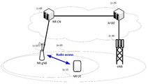
도 1c는 일 실시예가 적용되는 차세대 이동통신 시스템의 구조를 도시하는 도면이다. 1C is a diagram showing the structure of a next-generation mobile communication system to which an embodiment is applied.
도 1c를 참조하면, 차세대 이동통신 시스템(이하 NR 혹은 5G)의 무선 액세스 네트워크는 차세대 기지국(New Radio Node B, 이하 NR gNB 혹은 NR 기지국)(1c-10) 과 NR CN(1c-05, New Radio Core Network)로 구성될 수 있다. 사용자 단말(New Radio User Equipment, 이하 NR UE 또는 단말)(1c-15)은 NR gNB(1c-10) 및 NR CN(1c-05)를 통해 외부 네트워크에 접속할 수 있다.Referring to Figure 1c, the next generation mobile communication system (hereinafter referred to as NR or 5G) radio access network is a next-generation base station (New Radio Node B, NR gNB or NR base station) (1c-10) and NR CN (1c-05, New Radio Core Network). The user terminal (New Radio User Equipment, NR UE or terminal) 1c-15 may access an external network through the
도 1c에서 NR gNB(1c-10)는 기존 LTE 시스템의 eNB(Evolved Node B)에 대응된다. NR gNB(1c-10)는 NR UE(1c-15)와 무선 채널로 연결되며 노드 B 보다 더 월등한 서비스를 제공해줄 수 있다. 차세대 이동통신 시스템에서는 모든 사용자 트래픽이 공용 채널(shared channel)을 통해 서비스 되므로, UE들의 버퍼 상태, 가용 전송 전력 상태, 채널 상태 등의 상태 정보를 취합해서 스케줄링을 하는 장치가 필요하며, 이를 NR NB(1c-10)가 담당한다. 하나의 NR gNB(1c-10)는 통상 다수의 셀들을 제어한다. 현재 LTE 대비 초고속 데이터 전송을 구현하기 위해서 기존 최대 대역폭 이상을 가질 수 있고, 직교 주파수 분할 다중 방식(Orthogonal Frequency Division Multiplexing, 이하 OFDM이라 한다)을 무선 접속 기술로 하여 추가적으로 빔포밍 기술이 접목될 수 있다. 또한, 단말의 채널 상태에 맞춰 변조 방식(modulation scheme)과 채널 코딩률(channel coding rate)을 결정하는 적응 변조 코딩(Adaptive Modulation & Coding, 이하 AMC라 한다) 방식을 적용할 수 있다. NR CN(1c-05)는 이동성 지원, 베어러 설정, QoS(Quality of Service) 설정 등의 기능을 수행할 수 있다. NR CN(1c-05)는 단말에 대한 이동성 관리 기능은 물론 각종 제어 기능을 담당하는 장치로 다수의 기지국들과 연결될 수 있다. 또한, 차세대 이동통신 시스템은 기존 LTE 시스템과도 연동될 수 있으며, NR CN(1c-05)이 MME(1c-25)와 네트워크 인터페이스를 통해 연결될 수 있다. MME(1c-25)는 기존 기지국인 eNB(1c-30)과 연결될 수 있다.In Figure 1c, NR gNB (1c-10) corresponds to the evolved Node B (eNB) of the existing LTE system. NR gNB (1c-10) is connected to the NR UE (1c-15) in a wireless channel and can provide a service superior to Node B. In the next-generation mobile communication system, since all user traffic is serviced through a shared channel, a device is required to collect and schedule status information such as buffer status of UEs, available transmission power status, and channel status, and this is NR NB (1c-10) is in charge. One
도 1d는 일 실시예가 적용되는 차세대 이동통신 시스템의 무선 프로토콜 구조를 나타낸 도면이다. .1D is a diagram illustrating a radio protocol structure of a next-generation mobile communication system to which an embodiment is applied. .
도 1d를 참조하면, 차세대 이동통신 시스템의 무선 프로토콜은 단말과 NR 기지국에서 각각 NR SDAP(Service Data Adaptation Protocol)(1d-01, 1d-45), NR PDCP(Packet Data Convergence Protocol)(1d-05, 1d-40), NR RLC(1d-10, 1d-35) 및 NR MAC(1d-15, 1d-30)으로 이루어질 수 있다. NR SDAP(1d-01, 1d-45)의 주요 기능은 다음의 기능들 중 일부를 포함할 수 있다.Referring to Figure 1d, the radio protocol of the next-generation mobile communication system is NR Service Data Adaptation Protocol (SDAP) (1d-01, 1d-45), NR Packet Data Convergence Protocol (PDCP) (1d-05) at the terminal and the NR base station, respectively. , 1d-40), NR RLC (1d-10, 1d-35) and NR MAC (1d-15, 1d-30). The main functions of the NR SDAP (1d-01, 1d-45) may include some of the following functions.
- 사용자 데이터의 전달 기능(transfer of user plane data)-Transfer of user plane data
- 상향 링크와 하향 링크에 대해서 QoS flow와 데이터 베어러의 맵핑 기능(mapping between a QoS flow and a DRB for both DL and UL)-Mapping function between QoS flow and data bearer for uplink and downlink (mapping between a QoS flow and a DRB for both DL and UL)
- 상향 링크와 하향 링크에 대해서 QoS flow ID를 마킹 기능(marking QoS flow ID in both DL and UL packets)-Marking QoS flow ID for both uplink and downlink (marking QoS flow ID in both DL and UL packets)
- 상향 링크 SDAP PDU들에 대해서 relective QoS flow를 데이터 베어러에 맵핑시키는 기능 (reflective QoS flow to DRB mapping for the UL SDAP PDUs). -Reflective QoS flow to DRB mapping for the UL SDAP PDUs for uplink SDAP PDUs.
상술한 SDAP 계층 장치에 대해 단말은 RRC 메시지로 각 PDCP 계층 장치 별로 혹은 베어러 별로 혹은 로지컬 채널 별로 SDAP 계층 장치의 헤더를 사용할 지 여부 혹은 SDAP 계층 장치의 기능을 사용할 지 여부를 설정 받을 수 있으며, SDAP 헤더가 설정된 경우, SDAP 헤더의 NAS QoS(Non-Access Stratum Quality of Service) 반영 설정 1비트 지시자(NAS reflective QoS)와 AS QoS 반영 설정 1비트 지시자(AS reflective QoS)로 단말이 상향 링크와 하향 링크의 QoS flow와 데이터 베어러에 대한 맵핑 정보를 갱신 혹은 재설정할 수 있도록 지시할 수 있다. 상술된 SDAP 헤더는 QoS를 나타내는 QoS flow ID 정보를 포함할 수 있다. 상술된 QoS 정보는 원할한 서비스를 지원하기 위한 데이터 처리 우선 순위, 스케쥴링 정보 등으로 사용될 수 있다. For the above-described SDAP layer device, the UE can set whether to use the header of the SDAP layer device or the function of the SDAP layer device, for each PDCP layer device, for each bearer, or for each logical channel, as an RRC message. When the header is set, the terminal is uplinked and downlinked by NAS non-access stratum quality of service (NAS QoS) setting 1-bit indicator (NAS reflective QoS) and AS QoS reflection setting 1-bit indicator (AS reflective QoS) in the SDAP header. It can instruct to update or reset the QoS flow and mapping information for the data bearer. The SDAP header described above may include QoS flow ID information indicating QoS. The above-described QoS information can be used as data processing priority, scheduling information, etc. to support a smooth service.
NR PDCP(1d-05, 1d-40)의 주요 기능은 다음의 기능들 중 일부를 포함할 수 있다. The main functions of the NR PDCP (1d-05, 1d-40) may include some of the following functions.
- 헤더 압축 및 압축 해제 기능(Header compression and decompression: ROHC only)-Header compression and decompression (ROHC only)
- 사용자 데이터 전송 기능 (Transfer of user data)-Transfer of user data
- 순차적 전달 기능(In-sequence delivery of upper layer PDUs)-In-sequence delivery of upper layer PDUs
- 비순차적 전달 기능 (Out-of-sequence delivery of upper layer PDUs)-Out-of-sequence delivery of upper layer PDUs
- 순서 재정렬 기능(PDCP PDU reordering for reception)-Reordering function (PDCP PDU reordering for reception)
- 중복 탐지 기능(Duplicate detection of lower layer SDUs)-Duplicate detection of lower layer SDUs
- 재전송 기능(Retransmission of PDCP SDUs)-Retransmission of PDCP SDUs
- 암호화 및 복호화 기능(Ciphering and deciphering)-Encryption and decryption function (Ciphering and deciphering)
- 타이머 기반 SDU 삭제 기능(Timer-based SDU discard in uplink.)-Timer-based SDU discard function (Timer-based SDU discard in uplink.)
여기서, NR PDCP 장치의 순서 재정렬 기능(reordering)은 하위 계층에서 수신한 PDCP PDU들을 PDCP SN(sequence number)을 기반으로 순서대로 재정렬하는 기능 및 재정렬된 순서대로 데이터를 상위 계층에 전달하는 기능을 포함할 수 있다. 또는 NR PDCP 장치의 순서 재정렬 기능(reordering)은, 순서를 고려하지 않고, 바로 전달하는 기능, 순서를 재정렬하여 유실된 PDCP PDU들을 기록하는 기능, 유실된 PDCP PDU들에 대한 상태 보고를 송신 측에 하는 기능, 유실된 PDCP PDU들에 대한 재전송을 요청하는 기능 중 적어도 하나를 포함할 수 있다. Here, the order reordering function of the NR PDCP device includes a function of reordering PDCP PDUs received from a lower layer in order based on a PDCP sequence number (SN) and a function of delivering data to a higher layer in reordered order. can do. Or, the reordering function of the NR PDCP device (reordering) does not take the order into account, the function of immediately transmitting, reordering the function to record the lost PDCP PDUs, and reporting the status of the lost PDCP PDUs to the transmitting side And at least one of a function for requesting retransmission for lost PDCP PDUs.
NR RLC(1d-10, 1d-35)의 주요 기능은 다음의 기능들 중 일부를 포함할 수 있다.The main functions of the NR RLC (1d-10, 1d-35) may include some of the following functions.
- 데이터 전송 기능(Transfer of upper layer PDUs)-Data transfer function (Transfer of upper layer PDUs)
- 순차적 전달 기능(In-sequence delivery of upper layer PDUs)-In-sequence delivery of upper layer PDUs
- 비순차적 전달 기능(Out-of-sequence delivery of upper layer PDUs)-Out-of-sequence delivery of upper layer PDUs
- ARQ 기능(Error Correction through ARQ)-ARQ function (Error Correction through ARQ)
- 접합, 분할, 재조립 기능(Concatenation, segmentation and reassembly of RLC SDUs)-Concatenation, segmentation and reassembly of RLC SDUs
- 재분할 기능(Re-segmentation of RLC data PDUs)-Re-segmentation of RLC data PDUs
- 순서 재정렬 기능(Reordering of RLC data PDUs)-Reordering of RLC data PDUs
- 중복 탐지 기능(Duplicate detection)-Duplicate detection function
- 오류 탐지 기능(Protocol error detection)-Protocol error detection
- RLC SDU 삭제 기능(RLC SDU discard)-RLC SDU deletion function (RLC SDU discard)
- RLC 재수립 기능(RLC re-establishment)-RLC re-establishment
여기서, NR RLC 장치의 순차적 전달 기능(In-sequence delivery)은 하위 계층으로부터 수신한 RLC SDU들을 순서대로 상위 계층에 전달하는 기능을 말한다. NR RLC 장치의 순차적 전달 기능(In-sequence delivery)은 원래 하나의 RLC SDU가 여러 개의 RLC SDU들로 분할되어 수신된 경우, 이를 재조립하여 전달하는 기능, 수신한 RLC PDU들을 RLC SN(sequence number) 혹은 PDCP SN(sequence number)를 기준으로 재정렬하는 기능, 순서를 재정렬하여 유실된 RLC PDU들을 기록하는 기능, 유실된 RLC PDU들에 대한 상태 보고를 송신 측에 하는 기능, 유실된 RLC PDU들에 대한 재전송을 요청하는 기능, 유실된 RLC SDU가 있을 경우, 유실된 RLC SDU 이전까지의 RLC SDU들만을 순서대로 상위 계층에 전달하는 기능, 혹은 유실된 RLC SDU가 있어도 소정의 타이머가 만료되었다면 타이머가 시작되기 전에 수신된 모든 RLC SDU들을 순서대로 상위 계층에 전달하는 기능, 혹은 유실된 RLC SDU가 있어도 소정의 타이머가 만료되었다면 현재까지 수신된 모든 RLC SDU들을 순서대로 상위 계층에 전달하는 기능 중등을 포함할 수 있다. Here, the in-sequence delivery of the NR RLC device refers to a function of sequentially transmitting RLC SDUs received from a lower layer to an upper layer. In-sequence delivery of the NR RLC device is a function of reassembling and transmitting when one RLC SDU is originally divided into several RLC SDUs and receiving RLC PDUs through RLC sequence number ) Or PDCP reordering based on SN (sequence number), the ability to rearrange the order to record the lost RLC PDUs, the ability to report the status of the lost RLC PDUs to the sender, the lost RLC PDUs A function to request retransmission for a function, a function to deliver only RLC SDUs up to the previous layer in order, if there is a lost RLC SDU, or a timer if the specified timer expires even if there is a lost RLC SDU Includes the ability to deliver all RLC SDUs received before start to the upper layer in order, or to deliver all RLC SDUs received to the upper layer in order if the timer expires even if there is a missing RLC SDU. can do.
또한, NR RLC 장치의 비순차적 전달 기능(Out-of-sequence delivery)은 RLC PDU들을 수신하는 순서대로(일련번호, Sequence number의 순서와 상관없이, 도착하는 순으로) 처리하여 PDCP 장치로 순서와 상관없이(Out-of sequence delivery) 전달할 수도 있으며, segment 인 경우에는 버퍼에 저장되어 있거나 추후에 수신될 segment들을 수신하여 온전한 하나의 RLC PDU로 재구성한 후, 처리하여 PDCP 장치로 전달할 수 있다. 상술된 NR RLC 계층은 접합(Concatenation) 기능을 포함하지 않을 수 있고 상술된 기능을 NR MAC 계층에서 수행하거나 NR MAC 계층의 다중화(multiplexing) 기능으로 대체할 수 있다. In addition, the out-of-sequence delivery function of the NR RLC device processes the RLC PDUs in the order in which they are received (regardless of the sequence number and sequence number order, in the order of arrival), and the sequence is sent to the PDCP device. It can be delivered regardless of (out-of-sequence delivery). In the case of segments, segments stored in a buffer or to be received at a later time can be received and reconstructed into a complete RLC PDU, processed, and then delivered to a PDCP device. The above-described NR RLC layer may not include a concatenation function, and may perform the above-described function in the NR MAC layer or replace it with a multiplexing function of the NR MAC layer.
NR RLC 장치의 비순차적 전달 기능(Out-of-sequence delivery)은 하위 계층으로부터 수신한 RLC SDU들을 순서와 상관없이 바로 상위 계층으로 전달하는 기능을 포함할 수 있다. RLC 장치의 비순차적 전달 기능(Out-of-sequence delivery)은 원래 하나의 RLC SDU가 여러 개의 RLC SDU들로 분할되어 수신된 경우, 이를 재조립하여 전달하는 기능, 수신한 RLC PDU들의 RLC SN 혹은 PDCP SN을 저장하고 순서를 정렬하여 유실된 RLC PDU들을 기록해두는 기능 중 적어도 하나를 포함할 수 있다. The out-of-sequence delivery function of the NR RLC device may include a function of delivering RLC SDUs received from a lower layer directly to an upper layer regardless of order. The out-of-sequence delivery function of the RLC device is a function of reassembling and delivering when one RLC SDU is originally divided into several RLC SDUs, RLC SN of received RLC PDUs, or It may include at least one of a function of storing PDCP SNs and arranging the order to record lost RLC PDUs.
NR MAC(1d-15, 1d-30)은 한 단말에 구성된 여러 NR RLC 계층 장치들과 연결될 수 있으며, NR MAC의 주요 기능은 다음의 기능들 중 일부를 포함할 수 있다. NR MAC (1d-15, 1d-30) may be connected to several NR RLC layer devices configured in one terminal, the main function of the NR MAC may include some of the following functions.
- 맵핑 기능(Mapping between logical channels and transport channels)-Mapping function (Mapping between logical channels and transport channels)
- 다중화 및 역다중화 기능(Multiplexing/demultiplexing of MAC SDUs)-Multiplexing/demultiplexing of MAC SDUs
- 스케쥴링 정보 보고 기능(Scheduling information reporting)-Scheduling information reporting function
- HARQ 기능(Error correction through HARQ)-HARQ function (Error correction through HARQ)
- 로지컬 채널 간 우선 순위 조절 기능(Priority handling between logical channels of one UE)-Priority handling between logical channels (Priority handling between logical channels of one UE)
- 단말 간 우선 순위 조절 기능(Priority handling between UEs by means of dynamic scheduling)-Priority handling between UEs (Priority handling between UEs by means of dynamic scheduling)
- MBMS 서비스 확인 기능(MBMS service identification)-MBMS service identification function
- 전송 포맷 선택 기능(Transport format selection)-Transport format selection function
- 패딩 기능(Padding)-Padding function
NR PHY 계층(1d-20, 1d-25)은 상위 계층 데이터를 채널 코딩 및 변조하고, OFDM 심벌로 만들어서 무선 채널로 전송하거나, 무선 채널을 통해 수신한 OFDM 심벌을 복조하고 채널 디코딩해서 상위 계층으로 전달하는 동작을 수행할 수 있다.The NR PHY layer (1d-20, 1d-25) channel-codes and modulates upper layer data, makes it an OFDM symbol and transmits it to a radio channel, or demodulates and decodes an OFDM symbol received through a radio channel to a higher layer. You can perform the transfer operation.
도 1e는 일 실시예에 따른 단말과 네트워크의 연결을 설정하는 절차를 나타낸 도면이다.1E is a diagram illustrating a procedure for establishing a connection between a terminal and a network according to an embodiment.
도 1e를 참조하면, 기지국(gNB)은 RRC 연결 모드에서 데이터를 송수신하는 단말(UE)이 소정의 이유로 또는 일정 시간 동안 데이터의 송수신이 없으면 RRCConnectionRelease 메시지를 단말(UE)에게 보내어 단말(UE)을 RRC 유휴 모드 또는 RRC 비활성화 모드로 전환하도록 할 수 있다(1e-01). 추후에 현재 연결이 설정되어 있지 않은 단말(이하, idle mode UE)은 전송할 데이터가 발생하면 기지국(gNB)과 RRC connection establishment과정 또는 RRC Connection resume 절차를 수행할 수 있다. Referring to FIG. 1E, the base station (gNB) sends an RRCConnectionRelease message to the terminal (UE) when the terminal (UE) transmitting and receiving data in the RRC connection mode has no transmission or reception of data for a predetermined reason or for a predetermined time. It can be switched to the RRC idle mode or the RRC inactive mode (1e-01). Subsequently, a terminal that is not currently connected (hereinafter referred to as an idle mode UE) may perform an RRC connection establishment process or an RRC connection resume procedure with a base station (gNB) when data to be transmitted occurs.
단말(UE)은 랜덤 액세스 과정을 통해서 기지국(gNB)과 역방향 전송 동기를 수립하고 RRCConnectionRequest 메시지를 기지국(gNB)으로 전송한다(1e-05). RRCConnectionRequest 메시지에는 단말(UE)의 식별자와 연결을 설정하고자 하는 이유(establishmentCause) 등이 포함될 수 있다. The terminal (UE) establishes reverse transmission synchronization with the base station (gNB) through a random access process and transmits an RRCConnectionRequest message to the base station (gNB) (1e-05). The RRCConnectionRequest message may include an identifier of a terminal (UE) and a reason for establishing a connection (establishmentCause).
기지국(gNB)은 단말(UE)이 RRC 연결을 설정하도록 RRCConnectionSetup 메시지를 전송한다(1e-10). RRCConnectionSetup 메시지에는 각 로지컬 채널 별 설정 정보, 베어러 별 설정 정보,PDCP 계층 장치의 설정 정보, RLC 계층 장치의 설정 정보, 및 MAC 계층 장치의 설정 정보 중 적어도 하나가 포함될 수 있다. The base station (gNB) transmits an RRCConnectionSetup message to the UE to establish an RRC connection (1e-10). The RRCConnectionSetup message may include at least one of configuration information for each logical channel, configuration information for each bearer, configuration information for a PDCP layer device, configuration information for an RLC layer device, and configuration information for a MAC layer device.
기지국(gNB)은 RRCConnectionSetup 메시지를 통해 각 베어러에 대해서 베어러 식별자(예를 들면, SRB 식별자 또는 DRB 식별자)를 할당하고, 각 베어러에 대해 PDCP 계층 장치, RLC 계층 장치, MAC 계층 장치, PHY 계층 장치 설정을 지시할 수 있으며, 로지컬 채널 식별자의 맵핑을 지시할 수도 있다. 또한, 기지국(gNB)은 RRCConnectionSetup 메시지를 통해 각 베어러 별로 PDCP 계층 장치에서 사용하는 PDCP 일련번호의 길이(예를 들면, 12비트 또는 18비트)를 설정할 수 있으며, RLC 계층 장치에서 사용하는 RLC 일련번호의 길이(예를 들면, 6비트 또는 12비트 또는 18비트)를 설정할 수 있다. The base station (gNB) allocates a bearer identifier (eg, SRB identifier or DRB identifier) for each bearer through the RRCConnectionSetup message, and sets the PDCP layer device, RLC layer device, MAC layer device, and PHY layer device for each bearer. And may indicate mapping of the logical channel identifier. In addition, the base station (gNB) can set the length (for example, 12 bits or 18 bits) of the PDCP serial number used by the PDCP layer device for each bearer through the RRCConnectionSetup message, and the RLC serial number used by the RLC layer device. You can set the length of (for example, 6 bits or 12 bits or 18 bits).
또한, 기지국(gNB)은 RRCConnectionSetup 메시지를 통해 각 베어러 별(SRB 또는 DRB)로 본 개시에서 설명하는 RRC 메시지 또는 데이터의 분할 방법 및 재조립 방법을 PDCP 계층 장치 또는 SDAP 계층 장치 또는 RRC 계층 장치 또는 새로운 계층 장치에서 사용할 것인지 여부 등을 지시할 수 있다. 또한, 새로운 계층 장치에서 RRC 메시지 또는 데이터의 분할 방법 및 재조립 방법을 사용하는 경우, 새로운 계층 장치의 헤더를 사용할지 여부를 지시할 수도 있다. 예를 들면, 본 개시에서 설명하는 RRC 메시지 또는 데이터의 분할 방법 및 재조립 방법을 사용하도록 설정된 경우, 새로운 계층 장치의 헤더를 사용할 수 있으며, 본 개시에서 설명하는 RRC 메시지 또는 데이터의 분할 방법 및 재조립 방법을 사용하지 않도록 설정된 경우, 새로운 계층 장치의 헤더를 사용하지 않을 수 있다. In addition, the base station (gNB) is a PDCP layer device or SDAP layer device or RRC layer device or a new method for partitioning and reassembling the RRC message or data described in the present disclosure for each bearer (SRB or DRB) through the RRCConnectionSetup message. It may indicate whether or not to use the layer device. In addition, when the RRC message or data division method and re-assembly method are used in the new layer device, it may indicate whether to use the header of the new layer device. For example, when it is set to use the RRC message or data partitioning method and reassembly method described in the present disclosure, a header of a new layer device may be used, and the RRC message or data partitioning method and data described in the present disclosure may be used. If the assembly method is not used, the header of the new layer device may not be used.
RRC 연결을 설정한 단말(UE)은 RRCConnetionSetupComplete 메시지를 기지국(gNB)으로 전송한다(1e-15). RRCConnetionSetupComplete 메시지는 단말(UE)이 소정의 서비스를 위한 베어러 설정을 AMF 또는 MME에게 요청하는 SERVICE REQUEST라는 제어 메시지를 포함할 수 있다. 기지국(gNB)은 RRCConnetionSetupComplete 메시지에 수납된 SERVICE REQUEST 메시지를 AMF 또는 MME로 전송한다(1e-20). AMF 또는 MME는 단말(UE)이 요청한 서비스를 제공할지 여부를 판단할 수 있다. The UE establishing the RRC connection transmits an RRCConnetionSetupComplete message to the base station (gNB) (1e-15). The RRCConnetionSetupComplete message may include a control message called SERVICE REQUEST in which the UE requests the AMF or MME for bearer setup for a given service. The base station (gNB) transmits the SERVICE REQUEST message stored in the RRCConnetionSetupComplete message to the AMF or MME (1e-20). The AMF or MME can determine whether to provide the service requested by the UE.
판단 결과 단말(UE)이 요청한 서비스를 제공하기로 결정하였다면 AMF 또는 MME는 기지국(gNB)에게 INITIAL CONTEXT SETUP REQUEST라는 메시지를 전송한다(1e-25). INITIAL CONTEXT SETUP REQUEST 메시지에는 DRB(Data Radio Bearer) 설정 시 적용할 QoS(Quality of Service) 정보, 그리고 DRB에 적용할 보안 관련 정보(예를 들어, Security Key, Security Algorithm) 등의 정보가 포함될 수 있다. As a result of the determination, if the UE decides to provide the requested service, the AMF or MME sends a message called INITIAL CONTEXT SETUP REQUEST to the base station (gNB) (1e-25). The INITIAL CONTEXT SETUP REQUEST message may include QoS (Quality of Service) information to be applied when setting a Data Radio Bearer (DRB), and security-related information (eg, Security Key, Security Algorithm) to be applied to the DRB. .
기지국(gNB)은 단말(UE)과 보안을 설정하기 위해서 SecurityModeCommand 메시지(1e-30)와 SecurityModeComplete 메시지(1e-35)를 교환한다. 보안 설정이 완료되면 기지국(gNB)은 단말(UE)에게 RRCConnectionReconfiguration 메시지를 전송한다(1e-40). The base station (gNB) exchanges the SecurityModeCommand message (1e-30) and the SecurityModeComplete message (1e-35) to establish security with the terminal (UE). When the security setting is completed, the base station (gNB) transmits an RRCConnectionReconfiguration message to the UE (1e-40).
기지국(gNB)은 RRCConnectionReconfiguration 메시지를 통해 각 베어러에 대해서 베어러 식별자(예를 들면, SRB 식별자 또는 DRB 식별자)를 할당하고, 각 베어러에 대해 PDCP 계층 장치, RLC 계층 장치, MAC 계층 장치, PHY 계층 장치 설정을 지시할 수 있으며, 로지컬 채널 식별자의 맵핑을 지시할 수 있다. 또한, 기지국(gNB)은 RRCConnectionSetup 메시지를 통해 베어러 별로 PDCP 계층 장치에서 사용하는 PDCP 일련번호의 길이(예를 들면, 12비트 또는 18비트)를 설정할 수 있으며, RLC 계층 장치에서 사용하는 RLC 일련번호의 길이(예를 들면, 6비트 또는 12비트 또는 18비트)를 설정할 수 있다. The base station (gNB) allocates a bearer identifier (eg, SRB identifier or DRB identifier) for each bearer through an RRCConnectionReconfiguration message, and sets a PDCP layer device, RLC layer device, MAC layer device, and PHY layer device for each bearer. Can indicate, and may indicate the mapping of the logical channel identifier. In addition, the base station (gNB) can set the length (for example, 12 bits or 18 bits) of the PDCP serial number used in the PDCP layer device for each bearer through the RRCConnectionSetup message, and the RLC serial number used in the RLC layer device. The length (for example, 6 bits or 12 bits or 18 bits) can be set.
또한, 기지국(gNB)은 RRCConnectionReconfiguration 메시지에서 각 베어러 별(SRB 또는 DRB)로 본 개시에서 설명하는 RRC 메시지 또는 데이터의 분할 방법 및 재조립 방법을 PDCP 계층 장치 또는 SDAP 계층 장치 또는 RRC 계층 장치 또는 새로운 계층 장치에서 사용할 것인지 여부를 지시할 수 있다. 또한, 새로운 계층 장치에서 RRC 메시지 또는 데이터의 분할 방법 및 재조립 방법을 사용하는 경우, 새로운 계층 장치의 헤더를 사용할지 여부를 지시할 수 있다. 예를 들면, 본 개시에서 설명하는 RRC 메시지 또는 데이터의 분할 방법 및 재조립 방법을 사용하도록 설정된 경우, 새로운 계층 장치의 헤더를 사용할 수 있으며, 본 개시에서 설명하는 RRC 메시지 또는 데이터의 분할 방법 및 재조립 방법을 사용하지 않도록 설정된 경우, 새로운 계층 장치의 헤더를 사용하지 않을 수 있다. In addition, the base station (gNB) in the RRCConnectionReconfiguration message for each bearer (SRB or DRB) RRC message described in the present disclosure or a method of re-assembly of the data and PDCP layer device or SDAP layer device or RRC layer device or new layer It can indicate whether or not to use the device. In addition, when the RRC message or data division method and reassembly method are used in the new layer device, it may indicate whether to use the header of the new layer device. For example, when it is set to use the RRC message or data partitioning method and reassembly method described in the present disclosure, a header of a new layer device may be used, and the RRC message or data partitioning method and data described in the present disclosure may be used. If the assembly method is not used, the header of the new layer device may not be used.
또한, RRCConnectionReconfiguration 메시지에는 사용자 데이터가 처리될 DRB의 설정 정보가 포함될 수 있으며, 단말(UE)은 해당 정보를 적용해서 DRB를 설정하고 기지국(gNB)에게 RRCConnectionReconfigurationComplete 메시지를 전송한다(1e-45). 단말(UE)과 DRB 설정을 완료한 기지국(gNB)은 AMF 또는 MME에게 INITIAL CONTEXT SETUP COMPLETE 메시지를 전송하고 연결을 완료할 수 있다(1e-50). In addition, the RRCConnectionReconfiguration message may include configuration information of the DRB to which user data is to be processed, and the UE configures the DRB by applying the information and transmits the RRCConnectionReconfigurationComplete message to the base station (gNB) (1e-45). The terminal (UE) and the base station (gNB) that has completed the DRB setup may send an INITIAL CONTEXT SETUP COMPLETE message to the AMF or MME and complete the connection (1e-50).
이러한 과정이 모두 완료되면 단말(UE)은 기지국(gNB)과 코어 네트워크를 통해 데이터를 송수신한다(1e-55, 1e-60). 일 실시예에 따르면, 데이터 전송 과정은 크게 RRC 연결 설정, 보안 설정, DRB 설정의 3단계로 구성될 수 있다. 또한, 기지국(gNB)은 소정의 이유로 단말(UE)에게 새로운 설정을 해주거나, 설정을 추가하거나 변경하기 위해서 RRC Connection Reconfiguration 메시지를 전송할 수 있다(1e-65). When all of these processes are completed, the UE transmits and receives data through the base station (gNB) and the core network (1e-55, 1e-60). According to an embodiment, the data transmission process may be largely composed of three steps: RRC connection setup, security setup, and DRB setup. In addition, the base station (gNB) may transmit an RRC Connection Reconfiguration message to make a new setting to the UE for a predetermined reason, or to add or change the setting (1e-65).
기지국(gNB)은 RRCConnectionReconfiguration 메시지를 통해 각 베어러에 대해서 베어러 식별자(예를 들면, SRB 식별자 또는 DRB 식별자)를 할당하고, 각 베어러에 대해 PDCP 계층 장치, RLC 계층 장치, MAC 계층 장치, PHY 계층 장치 설정을 지시할 수 있으며 로지컬 채널 식별자의 맵핑을 지시할 수 있다. 또한, 기지국(gNB)은 RRCConnectionSetup 메시지를 통해 각 베어러 별로 PDCP 계층 장치에서 사용하는 PDCP 일련번호의 길이(예를 들면, 12비트 또는 18비트)를 설정할 수 있으며, RLC 계층 장치에서 사용하는 RLC 일련번호의 길이(예를 들면, 6비트 또는 12비트 또는 18비트)를 설정할 수 있다. The base station (gNB) allocates a bearer identifier (eg, SRB identifier or DRB identifier) for each bearer through an RRCConnectionReconfiguration message, and sets a PDCP layer device, RLC layer device, MAC layer device, and PHY layer device for each bearer. Can indicate and may indicate the mapping of the logical channel identifier. In addition, the base station (gNB) can set the length (for example, 12 bits or 18 bits) of the PDCP serial number used by the PDCP layer device for each bearer through the RRCConnectionSetup message, and the RLC serial number used by the RLC layer device. You can set the length of (for example, 6 bits or 12 bits or 18 bits).
또한 RRCConnectionReconfiguration 메시지에서 각 베어러 별(SRB 또는 DRB)로 본 개시에서 설명하는 RRC 메시지 또는 데이터의 분할 방법 및 재조립 방법을 PDCP 계층 장치 또는 SDAP 계층 장치 또는 RRC 계층 장치 또는 새로운 계층 장치에서 사용할 것인지 여부를 지시할 수 있다. 또한, 새로운 계층 장치에서 RRC 메시지 또는 데이터의 분할 방법 및 재조립 방법을 사용하는 경우, 새로운 계층 장치의 헤더를 사용할지 여부를 지시할 수 있다. 예를 들면, 본 개시에서 설명하는 RRC 메시지 또는 데이터의 분할 방법 및 재조립 방법을 사용하도록 설정된 경우, 새로운 계층 장치의 헤더를 사용할 수 있으며, 본 개시에서 설명하는 RRC 메시지 또는 데이터의 분할 방법 및 재조립 방법을 사용하지 않도록 설정된 경우, 새로운 계층 장치의 헤더를 사용하지 않을 수 있다. In addition, whether or not to divide and reassemble the RRC message or data described in the present disclosure for each bearer (SRB or DRB) in the RRCConnectionReconfiguration message from the PDCP layer device or the SDAP layer device or the RRC layer device or the new layer device. I can order. In addition, when the RRC message or data division method and reassembly method are used in the new layer device, it may indicate whether to use the header of the new layer device. For example, when it is set to use the RRC message or data partitioning method and reassembly method described in the present disclosure, a header of a new layer device may be used, and the RRC message or data partitioning method and data described in the present disclosure may be used. If the assembly method is not used, the header of the new layer device may not be used.
본 개시에서 설명하는 단말(UE)과 기지국(gNB)과의 연결 설정 절차는 단말(UE)과 LTE 기지국(gNB)과의 연결 설정에도 적용될 수 있으며, 단말(UE)과 NR 기지국(gNB)과의 연결 설정에도 적용될 수 있다. The procedure for establishing a connection between a UE (UE) and a base station (gNB) described in the present disclosure may be applied to establishing a connection between a UE (UE) and an LTE base station (gNB), and a UE (UE) and an NR base station (gNB). It can be applied to the connection setting of.
본 개시에서 베어러는 SRB(Signaling Radio Bearer)와 DRB(Data Radio Bearer)를 포함할 수 있다. SRB는 주로 RRC 계층 장치의 RRC 메시지를 전송하고 수신하는데 사용되며, DRB는 주로 사용자 계층 데이터들을 전송하고 수신하는데 사용된다. 그리고 UM DRB는 UM(Unacknowledged Mode) 모드로 동작하는 RLC 계층 장치를 사용하는 DRB를 의미하며, AM DRB는 AM(Acknowledged Mode) 모드로 동작하는 RLC 계층 장치를 사용하는 DRB를 의미한다. In the present disclosure, the bearer may include a signaling radio bearer (SRB) and a data radio bearer (DRB). The SRB is mainly used to transmit and receive RRC messages of the RRC layer device, and the DRB is mainly used to transmit and receive user layer data. In addition, the UM DRB means a DRB using an RLC layer device operating in the Unacknowledged Mode (UM) mode, and the AM DRB means a DRB using an RLC layer device operating in the AM (Acknowledged Mode) mode.
본 개시에서 설명하는 상위 계층 데이터(RRC 메시지 또는 사용자 계층 데이터)의 데이터 분할 방법 및 재조립 방법은 새로운 지시자를 정의하고(예를 들면, 1 비트 또는 2비트 지시자 또는 일련번호), 이 지시자를 기반으로 하여 RRC 계층 장치 또는 PDCP 계층 장치 또는 SDAP 계층 장치 또는 새로 정의하는 계층 장치에서 데이터를 분할 및 재조립하는 것을 특징으로 하며, PDCP 계층 장치 또는 그 위의 계층 장치의 데이터에 대해서 데이터를 분할 및 재조립하는 것을 특징으로 한다. 또한, 본 개시에서 설명하는 데이터 분할 방법 및 재조립 방법을 새로운 계층 장치에서 사용하는 경우, 새로운 지시자를 새로운 헤더에 정의하고 적용하는 것을 특징으로 한다. 본 개시에서 설명하는 상위 계층 데이터의 데이터 분할 방법 및 재조립 방법은 베어러 별로 설정되거나 또는 설정되지 않을 수 있다. The data division method and re-assembly method of upper layer data (RRC message or user layer data) described in the present disclosure define a new indicator (for example, a 1-bit or 2-bit indicator or serial number), and based on this indicator It characterized in that the data is divided and reassembled in the RRC layer device or PDCP layer device or SDAP layer device or newly defined layer device, and the data is divided and re-established for the data of the PDCP layer device or the layer device thereon. It is characterized by assembling. In addition, when the data division method and the reassembly method described in the present disclosure are used in a new layer device, it is characterized in that a new indicator is defined and applied to a new header. The data division method and re-assembly method of upper layer data described in the present disclosure may or may not be set for each bearer.
본 개시에서 단말 또는 기지국은 베어러 별로 본 개시에서 설명하는 상위 계층 데이터의 데이터 분할 방법 및 재조립 방법을 사용하거나 사용하지 않을 수 있다. 예를 들면, 특정 베어러에 본 개시에서 설명하는 상위 계층 데이터의 데이터 분할 방법 및 재조립 방법이 설정된 경우, 해당 특정 베어러에서 송수신되는 RRC 메시지 또는 데이터에 대해서 본 개시에서 설명하는 상위 계층 데이터의 데이터 분할 방법 및 재조립 방법을 항상 적용할 수 있으며, 새로운 계층 장치에서 적용하는 경우, 분할 정보를 포함하는 새로운 헤더를 항상 사용할 수 있다. 또한, 본 개시에서 설명하는 상위 계층 데이터의 데이터 분할 방법 및 재조립 방법이 설정되지 않은 베어러에 대해서는 항상 본 개시에서 설명하는 상위 계층 데이터의 데이터 분할 방법 및 재조립 방법을 적용하지 않을 수 있으며, 새로운 계층 장치에서 적용하는 경우, 분할 정보를 포함하는 새로운 헤더를 항상 사용하지 않을 수 있다.In the present disclosure, the terminal or the base station may or may not use a data division method and a reassembly method of higher layer data described in this disclosure for each bearer. For example, when a data splitting method and a reassembly method of higher layer data described in the present disclosure are set in a specific bearer, data of the upper layer data described in the present disclosure is divided into RRC messages or data transmitted and received in the specific bearer. The method and the reassembly method can always be applied, and when applied in a new layer device, a new header including segmentation information can always be used. In addition, the data segmentation method and reassembly method of the upper layer data described in this disclosure may not always be applied to a bearer in which the data segmentation method and reassembly method of the higher layer data described in the present disclosure are not set. When applied in a layer device, a new header including segmentation information may not always be used.
또 다른 방법으로 RRC 메시지 또는 사용자 계층 데이터의 크기에 기반한 라우팅 방법을 사용할 수도 있다. 본 개시에서 단말 또는 기지국은 RRC 메시지 또는 사용자 계층 데이터를 전송하려고 할 때 전송하려고 하는 RRC 메시지 또는 사용자 계층 데이터의 크기가 정해진 임계값(예를 들면, 9 kb)을 초과한다면 본 개시에서 설명하는 상위 계층 데이터의 데이터 분할 방법 및 재조립 방법이 적용된 베어러(예를 들면 새로운 SRB4 또는 SRB5 또는 DRB2)를 통하여 분할하고 RRC 메시지 또는 사용자 계층 데이터를 분할하여 전송할 수 있다. 즉, RRC 메시지 또는 사용자 계층 데이터에 대해 본 개시에서 설명하는 상위 계층 데이터의 데이터 분할 방법이 설정된 베어러에서 RRC 메시지 또는 사용자 계층 데이터에 대해서 분할 방법을 적용하고, 분할하여 RRC 메시지 또는 사용자 계층 데이터를 전송할 수 있다. 만약 단말 또는 기지국이 RRC 메시지 또는 사용자 계층 데이터를 전송하려고 할 때 전송하려고 하는 RRC 메시지 또는 사용자 계층 데이터의 크기가 정해진 임계값(예를 들,면 9 kb)을 초과하지 않는다면 본 개시에서 설명하는 상위 계층 데이터의 데이터 분할 방법 및 재조립 방법이 적용되지 않은 베어러(예를 들면, SRB0 또는 SRB1 또는 SRB2 또는 DRB1)를 통하여 RRC 메시지 또는 사용자 계층 데이터를 전송할 수 있다.As another method, a routing method based on the size of the RRC message or user layer data may be used. In the present disclosure, when the terminal or the base station attempts to transmit the RRC message or user layer data, if the size of the RRC message or user layer data to be transmitted exceeds a predetermined threshold (for example, 9 kb), a higher level described in the present disclosure It can be divided through a bearer (for example, new SRB4 or SRB5 or DRB2) to which the data division method and reassembly method of the layer data are applied, and the RRC message or user layer data can be divided and transmitted. That is, in the bearer in which the data division method of the upper layer data described in the present disclosure is set for the RRC message or user layer data, the division method is applied to the RRC message or user layer data, and the RRC message or user layer data is transmitted by division. Can. If the size of the RRC message or user layer data to be transmitted does not exceed a predetermined threshold (for example, 9 kb) when the terminal or the base station attempts to transmit the RRC message or user layer data, the higher level described in the present disclosure An RRC message or user layer data may be transmitted through a bearer (eg, SRB0 or SRB1 or SRB2 or DRB1) to which the data division method and the reassembly method of the layer data are not applied.
또 다른 방법으로, PDCP 계층 장치에서 지원하는 데이터의 크기(예를 들면, 9 kb)보다 큰 데이터 크기의 데이터 프로세싱을 지원하는 별도의 베어러(SRB 또는 DRB)를 정의하고 설정하여, PDCP 계층 장치에서 지원하는 데이터의 크기보다 큰 RRC 메시지나 데이터는 상술한 별도의 베어러를 통해서 데이터 처리를 수행하고 데이터 송수신을 가능하게 할 수도 있다. Alternatively, by defining and setting a separate bearer (SRB or DRB) supporting data processing of a data size larger than the size of the data supported by the PDCP layer device (for example, 9 kb), the PDCP layer device An RRC message or data larger than the size of the supported data may perform data processing through the separate bearer described above and enable data transmission and reception.
일 실시예에서 기지국은 단말의 능력 정보를 요청하고 단말 능력 보고 메시지를 수신하여 단말이 본 개시에서 설명하는 상위 계층 데이터의 데이터 분할 방법 및 재조립 방법을 지원하는지 여부를 확인할 수도 있다.In one embodiment, the base station may request whether the terminal supports capability information and receives a terminal capability report message to determine whether the terminal supports a data division method and a reassembly method of higher layer data described in the present disclosure.
도 1f는 일 실시예에 따른 기지국이 단말의 능력을 확인하기 위한 절차를 나타낸 도면이다. 1F is a diagram illustrating a procedure for a base station to check a terminal's capability according to an embodiment.
도 1f를 참조하면, 기지국(gNB)은 단말(UE)의 능력을 확인하기 위해서 UECapabilityEnqiry 메시지를 단말(UE)에게 전송하여 단말(UE)로 하여금 단말(UE) 능력을 보고하도록 할 수 있다. UECapabilityEnqiry 메시지를 RRC 메시지로서 수신하게 되면 단말(UE)은 단말 능력을 보고하기 위해 단말 능력들을 UECapabilityInformation 메시지에 구성하여 기지국(gNB)에게 전송함으로써 단말(UE) 능력을 보고할 수 있다. Referring to FIG. 1F, a base station (gNB) may transmit a UECapabilityEnqiry message to a terminal (UE) to check the capability of the terminal (UE) so that the terminal (UE) reports the capability of the terminal (UE). When the UECapabilityEnqiry message is received as an RRC message, the UE can report the UE capability by configuring the UE capabilities in the UECapabilityInformation message and sending it to the base station (gNB) to report the UE capability.
단말(UE)이 UECapabilityInformation 메시지를 전송할 때, 단말(UE)은 본 개시에서 설명하는 상위 계층 데이터의 데이터 분할 방법 및 재조립 방법을 지원한다는 지시자를 포함하여 전송할 수 있다.When the UE transmits the UECapabilityInformation message, the UE may include an indicator that supports a data division method and a reassembly method of higher layer data described in the present disclosure.
이와 같이 단말(UE)과 네트워크가 RRC 연결 설정 또는 재개 절차를 통하여 특정 베어러에 대해서 본 개시에서 설명하는 상위 계층 데이터의 데이터 분할 방법 및 재조립 방법을 설정하였지만, 만약 단말(UE)과 네트워크 간의 장애물 또는 전파 방해 또는 단말(UE)의 빠른 이동성으로 인해 신호 끊김 또는 RLF(Radio link Failure)가 발생한 경우, 단말(UE)과 기지국(gNB)은 연결을 다시 설정하기 위해 RRC 재수립 절차(RRC Connection Re-establishment)를 수행하게 된다. 이 때, 특정 베어러에 대한 상위 계층 데이터의 데이터 분할 방법 및 재조립 방법을 비활성화 또는 중지 또는 해제 또는 폴백 또는 사용하지 않을 수 있다. 즉, 단말(UE)이 RRC 연결 재수립 절차를 수행할 때에는 상위 계층 데이터의 데이터 분할 방법 및 재조립 방법을 적용하지 않을 수 있다. 예를 들면, 기지국(gNB)이 상위 계층 데이터의 데이터 분할 방법 및 재조립 방법을 특정 베어러에 대해 다시 설정해주기 전까지는 본 개시에서 설명하는 상위 계층 데이터의 데이터 분할 방법 및 재조립 방법을 적용하지 않을 수 있다(예를 들면, 새로운 계층 장치에서 상위 계층 데이터의 데이터 분할 방법 및 재조립 방법을 적용하는 경우, 새로운 헤더를 사용하지 않을 수 있다). 그리고 기지국(gNB)이 RRC 연결 재수립 절차 또는 RRC 메시지로 상위 계층 데이터의 데이터 분할 방법 및 재조립 방법을 특정 베어러에 대해 다시 설정해주면 본 개시에서 설명하는 상위 계층 데이터의 데이터 분할 방법 및 재조립 방법을 다시 적용할 수 있다(예를 들면 새로운 계층 장치에서 상위 계층 데이터의 데이터 분할 방법 및 재조립 방법을 적용하는 경우, 새로운 헤더를 다시 사용할 수 있다). As described above, although the UE and the network have established a data partitioning method and a reassembly method of higher layer data described in the present disclosure for a specific bearer through an RRC connection establishment or resumption procedure, if there is an obstacle between the UE and the network Alternatively, when signal loss or radio link failure (RLF) occurs due to radio interference or rapid mobility of the UE, the UE and the base station (gNB) re-establish the RRC connection procedure to establish a connection (RRC Connection Re -establishment). At this time, it is possible to deactivate or stop or release or fall back or not to use the data division method and the re-assembly method of upper layer data for a specific bearer. That is, when the UE performs the RRC connection re-establishment procedure, the data division method and re-assembly method of upper layer data may not be applied. For example, the data division method and reassembly method of the higher layer data described in the present disclosure will not be applied until the base station (gNB) resets the data division method and reassembly method of higher layer data for a specific bearer. (For example, when a data division method and a reassembly method of higher layer data are applied in a new layer device, a new header may not be used). In addition, when the base station (gNB) re-establishes a method for re-establishing data and re-assembling data of higher-layer data using an RRC connection re-establishment procedure or an RRC message, a data partitioning method and re-assembly method of higher-layer data described in the present disclosure. Can be applied again (for example, when a data division method and a reassembly method of higher layer data are applied in a new layer device, a new header may be used again).
또 다른 방법으로, 기지국(gNB)과 단말(UE)은 한 번 상위 계층 데이터의 데이터 분할 방법 및 재조립 방법이 설정된 베어러에 대해서는 구현의 편의를 위해서 RRC 재수립 절차에 대해서도 본 개시에서 설명하는 상위 계층 데이터의 데이터 분할 방법 및 재조립 방법을 계속해서 적용할 수도 있다. In another method, the base station (gNB) and the UE (UE) are described in the present disclosure about the RRC re-establishment procedure for convenience of implementation for a bearer in which a data division method and a re-assembly method of the upper layer data are set once. The method of dividing and reassembling data of hierarchical data may be continuously applied.
본 개시에서 설명하는 상위 계층 데이터의 데이터 분할 방법 및 재조립 방법이 새로운 계층 장치에서 적용되는 경우, 단말(UE)이 RRC 비활성화 모드 또는 RRC 유휴 모드로 천이할 때 새로운 계층 장치에 해당하는 버퍼에 저장되고 재조립이 수행되지 않은 분할된 데이터(세그먼트)들을 송신 새로운 계층 장치 또는 수신 새로운 계층 장치에서 모두 폐기하여 추후에 네트워크와 연결을 재설정할 때 발생할 수 있는 재조립 오류 또는 불필요한 전송의 오류를 방지할 수 있다. When the data division method and re-assembly method of the upper layer data described in the present disclosure are applied in a new layer device, when the UE transitions to the RRC inactive mode or the RRC idle mode, it is stored in a buffer corresponding to the new layer device. The re-assembled and segmented data (segments) that have not been re-assembled are all discarded by the transmitting new layer device or the receiving new layer device to prevent reassembly errors or unnecessary transmission errors that may occur when reestablishing the network and connection. Can.
그리고 RRC 비활성화 모드로 천이할 때 본 개시에서 설명하는 상위 계층 데이터의 데이터 분할 방법 및 재조립 방법은 중지(suspend)될 수 있으며, RRC 연결을 재설정할 때 네트워크의 지시에 의해서 재개(resume)될 수 있다. 그리고 RRC 유휴 모드로 천이할 때 본 개시에서 설명하는 상위 계층 데이터의 데이터 분할 방법 및 재조립 방법은 해제(release)될 수 있다. 새로운 계층 장치의 데이터 폐기 절차는 새로운 계층 장치의 재수립 절차로 정의될 수 있으며, PDCP 계층 장치가 재수립을 수행할 때 지시자를 새로운 계층 장치로 전송하여 폐기 절차를 트리거링 할 수도 있다. In addition, when transitioning to the RRC deactivation mode, the data division method and reassembly method of the upper layer data described in the present disclosure may be suspended, and may be resumed by an instruction of the network when resetting the RRC connection. have. In addition, when transitioning to the RRC idle mode, the data division method and reassembly method of the upper layer data described in the present disclosure may be released. The new layer device data discard procedure may be defined as a new layer device re-establishment procedure, and when the PDCP layer device performs re-establishment, an indicator may be transmitted to the new layer device to trigger the discard procedure.
아래에서는 본 개시에서 설명하는 상위 계층 데이터의 데이터 분할 방법 및 재조립 방법의 구체적인 실시예들을 설명한다.Hereinafter, specific embodiments of a data division method and a reassembly method of upper layer data described in the present disclosure will be described.
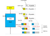
도 1g는 일 실시예에 따른 상위 계층 데이터의 데이터 분할 방법 및 재조립 방법의 제1 실시예를 나타낸 도면이다. 1G is a diagram illustrating a first embodiment of a data division method and a reassembly method of upper layer data according to an embodiment.
본 개시에서 설명하는 상위 계층 데이터의 데이터 분할 방법 및 재조립 방법의 제1 실시예는 새로운 계층 장치(SEG layer)를 정의하고, 새로운 계층 장치에서 새로운 헤더에 분할 및 재조립을 위한 필드들을 정의하며, 이를 송신단에서 분할하는 데에 사용하고, 수신단에서 재조립하는 데에 사용하는 것을 특징으로 한다. A first embodiment of a data division method and a reassembly method of upper layer data described in the present disclosure defines a new layer device (SEG layer), and defines fields for division and reassembly in a new header in the new layer device. It is characterized in that it is used for splitting at the transmitting end and used for reassembly at the receiving end.
상위 계층 데이터의 데이터 분할 방법 및 재조립 방법의 제1 실시예에서 새로운 계층 장치는 RRC 메시지를 송수신하는 SRB들에 대해서는 PDCP 계층 장치(1g-15)와 RRC 계층 장치(1g-05)와의 사이에서 위치할 수 있으며, 상위 계층 장치인 RRC 계층 장치로부터 데이터를 수신하고, 수신한 데이터가 PDCP 계층 장치에서 지원하는 최대 크기 또는 특정 임계값보다 큰 경우, 새로운 헤더를 구성하고, 분할 정보를 포함하여 해당 데이터를 분할하고 새로운 헤더를 부착하여 하위 PDCP 계층 장치로 전달할 수 있다. 만약 수신한 데이터가 PDCP 계층 장치에서 지원하는 최대 크기 또는 특정 임계값보다 작은 경우, 새로운 헤더를 구성하고, 분할되지 않았다는 지시를 분할 정보에 포함하여 해당 데이터에 부착하여 하위 PDCP 계층 장치로 전달할 수 있다. 이러한 새로운 헤더는 항상 존재할 수 있다. 하지만, 오버헤드를 줄이기 위해서, 맨 앞에 1 비트 지시자를 정의하여 새로운 헤더가 존재하는지 여부를 지시할 수도 있다. 예를 들면, 새로운 헤더 또는 PDCP 계층 장치의 헤더의 1 비트를 정의하여 새로운 헤더가 존재하는지 여부 또는 데이터가 분할되었는지 여부를 지시할 수 있다. 수신단에서 새로운 계층 장치는 하위 PDCP 계층 장치로부터 데이터를 수신하면 새로운 헤더를 읽어 들이고, 분할 정보를 확인하고, 분할되었다면 재조립을 수행하고, 분할되지 않았다면 헤더를 제거하고 상위 계층으로 RRC 메시지를 전달한다. In the first embodiment of the data division method and reassembly method of upper layer data, the new layer device is between the PDCP layer device (1g-15) and the RRC layer device (1g-05) for SRBs that transmit and receive RRC messages. It can be located and receives data from the upper layer device, the RRC layer device, and if the received data is larger than the maximum size or a specific threshold supported by the PDCP layer device, a new header is configured and includes the segmentation information. Data can be divided and attached with a new header to be delivered to the lower PDCP layer device. If the received data is smaller than the maximum size or a specific threshold supported by the PDCP layer device, a new header may be configured, and an indication that the data is not split may be included in the segmentation information and attached to the data to be transmitted to the lower PDCP layer device. . This new header can always be present. However, to reduce overhead, a 1-bit indicator may be defined at the beginning to indicate whether a new header exists. For example, a new header or 1 bit of the header of the PDCP layer device may be defined to indicate whether a new header exists or whether data is divided. At the receiving end, the new layer device receives data from the lower PDCP layer device, reads the new header, checks the segmentation information, performs reassembly if it is segmented, removes the header if it is not segmented, and delivers an RRC message to the upper layer. .
상위 계층 데이터의 데이터 분할 방법 및 재조립 방법의 제1 실시예에서 새로운 계층 장치는 사용자 계층 데이터를 송수신하는 DRB들에 대해서는 PDCP 계층 장치(1g-50)와 SDAP 계층 장치(1g-60)와의 사이에서 위치할 수 있으며, 상위 계층 장치인 SDAP 계층 장치 또는 상위 계층 장치(SDAP 계층 장치가 설정되지 않은 경우)로부터 데이터를 수신하고, 수신한 데이터가 PDCP 계층 장치에서 지원하는 최대 크기 또는 특정 임계값보다 큰 경우, 새로운 헤더를 구성하며, 분할 정보를 포함하여 해당 데이터를 분할하고 새로운 헤더를 부착하여 하위 PDCP 계층 장치로 전달할 수 있다. 만약, 수신한 데이터가 PDCP 계층 장치에서 지원하는 최대 크기 또는 특정 임계값보다 작은 경우, 새로운 헤더를 구성하고, 분할되지 않았다는 지시를 분할 정보에 포함하여 수신한 데이터에 부착하고 하위 PDCP 계층 장치로 전달할 수 있다. 이러한 새로운 헤더는 항상 존재할 수 있다. 하지만, 오버헤드를 줄이기 위해서, 맨 앞에 1 비트 지시자를 정의하여 새로운 헤더가 존재하는지 여부를 지시할 수 있다. 예를 들면, 새로운 헤더 또는 PDCP 계층 장치의 헤더의 1 비트를 정의하여 새로운 헤더가 존재하는지 여부 또는 데이터가 분할되었는지 여부를 지시해줄 수 있다. 수신단에서 새로운 계층 장치는 하위 PDCP 계층 장치로부터 데이터를 수신하면 새로운 헤더를 읽어 들이고, 분할 정보를 확인하고, 분할되었다면 재조립을 수행하고, 분할되지 않았다면 헤더를 제거하고 상위 계층으로 데이터를 전달한다.In the first embodiment of the data division method and reassembly method of upper layer data, the new layer device is between the PDCP layer device (1g-50) and the SDAP layer device (1g-60) for DRBs that transmit and receive user layer data. It can be located at and receives data from a higher layer device, SDAP layer device or higher layer device (if SDAP layer device is not set), and the received data is greater than the maximum size or a specific threshold supported by the PDCP layer device. In a large case, a new header may be configured, the corresponding data may be divided, including segmentation information, and a new header may be attached and transmitted to a lower PDCP layer device. If the received data is smaller than the maximum size or a specific threshold value supported by the PDCP layer device, a new header is configured, and the indication that the segment is not included is included in the segmentation information, attached to the received data, and transmitted to the lower PDCP layer device. Can. This new header can always be present. However, in order to reduce overhead, a 1-bit indicator may be defined at the beginning to indicate whether a new header exists. For example, a new header or 1 bit of the header of the PDCP layer device may be defined to indicate whether a new header exists or whether data is divided. When receiving data from the lower PDCP layer device, the new layer device at the receiving end reads the new header, checks the segmentation information, performs reassembly if it is segmented, removes the header if it is not segmented, and transfers the data to the upper layer.
도 1h은 일 실시예에 따른 상위 계층 데이터의 데이터 분할 방법 및 재조립 방법의 제1 실시예에 대한 구체적인 분할 및 재조립 방법을 나타낸 도면이다. 1H is a diagram illustrating a specific partitioning and reassembly method for a first embodiment of a data division method and a reassembly method of upper layer data according to an embodiment.
도 1h에서 1h-01은 상위 계층 데이터의 데이터 분할 방법 및 재조립 방법의 제1-1 실시예를 나타낸다. 1H to 1H-01 show a 1-1 embodiment of a data division method and a reassembly method of upper layer data.
제1-1 실시예에서 송신단과 수신단에서 2 비트의 S 필드(Segmentation field)를 정의하고 사용할 수 있다. S 필드는 00, 01, 11, 10의 4 가지 경우의 수에 대해서 분할되지 않은 완전한 데이터, 첫 번째 세그먼트(segment), 중간 세그먼트(또는 첫 번째와 마지막 세그먼트가 아닌 세그먼트), 마지막 세그먼트를 각각 지시하도록 정의할 수 있다. S 필드의 00, 01, 11, 10과 분할되지 않은 완전한 데이터, 첫 번째 세그먼트(segment), 중간 세그먼트(또는 첫 번째와 마지막 세그먼트가 아닌 세그먼트), 마지막 세그먼트에 대한 일대일 맵핑은 24 가지의 종류가 있을 수 있으며, 그 중에 하나로 매핑 관계를 정의할 수 있다. 예를 들면, 다음 [표 1]과 같이 S 필드를 정의할 수 있다. In the first-first embodiment, a 2-bit S field (segmentation field) may be defined and used by the transmitting end and the receiving end. The S field indicates complete data, first segment, middle segment (or segment other than the first and last segment), and last segment, respectively, for the four cases of 00, 01, 11, and 10. Can be defined as There are 24 kinds of one-to-one mapping for 00, 01, 11, 10 of S field, complete data that is not split, first segment, middle segment (or segment other than first and last segment), and last segment. It can be, and one of them can define the mapping relationship. For example, the S field can be defined as shown in [Table 1] below.
[표 1][Table 1]

도 1g에서 설명한 바와 같이, 새로 정의한 새로운 계층 장치(SEG layer, SEG 계층 장치)는 PDCP 계층 장치의 위에서 정의되고 사용되기 때문에, 수신 RLC 계층 장치가 AM 모드로 운영되는 경우, 유실이 없는 데이터 전송을 지원하고, 수신 PDCP 계층 장치에서 PDCP 일련번호 기준으로 데이터를 순서대로 정렬하여 수신 SEG 계층 장치로 전달하여 준다. 따라서, 새로운 계층 장치에서는 일련번호가 필요 없을 수 있으며, 2 비트 S 필드면 송신단에서 RRC 메시지 또는 데이터를 분할하고, 수신단에서 분할된 데이터를 성공적으로 재조립하여 수신할 수 있다. As illustrated in FIG. 1G, since the newly defined new layer device (SEG layer, SEG layer device) is defined and used above the PDCP layer device, when the receiving RLC layer device is operated in the AM mode, data transmission without loss is transmitted. It supports and sorts data in order by PDCP serial number from the receiving PDCP layer device and delivers it to the receiving SEG layer device. Therefore, in the new layer device, a serial number may not be required, and if the 2-bit S field is used, the RRC message or data may be divided by the transmitting end, and the divided data may be successfully reassembled and received at the receiving end.
상위 계층 데이터의 데이터 분할 방법 및 재조립 방법의 제1-1 실시예에 대한 송신단의 동작은 다음과 같다. The operation of the transmitting end for the first-first embodiment of the data division method and the re-assembly method of upper layer data is as follows.
새로운 계층 장치는 상위 계층 장치로부터 수신한 RRC 메시지 또는 데이터의 크기가 PDCP 계층 장치에서 지원하는 최대 크기 또는 특정 임계값보다 크다면 데이터 분할을 수행하고 크지 않다면 데이터 분할을 수행하지 않는다. The new layer device does not perform data segmentation if the size of the RRC message or data received from the higher layer device is greater than the maximum size or a specific threshold supported by the PDCP layer device, and if not, the data segmentation is not performed.
만약 데이터 분할을 수행했다면, 첫 번째 분할 데이터(세그먼트)의 경우, 새로운 헤더의 S 필드를 01로 설정하고, 첫 번째 분할 데이터(세그먼트)의 앞에 헤더를 부착하고 하위 계층 장치로 전달한다. 중간 분할 데이터(세그먼트)의 경우, 새로운 헤더의 S 필드를 11로 설정하고, 중간 분할 데이터(세그먼트)의 앞에 헤더를 부착하고 하위 계층 장치로 전달한다. 마지막 분할 데이터(세그먼트)의 경우, 새로운 헤더의 S 필드를 10로 설정하고, 마지막 분할 데이터의 앞에 헤더를 부착하고 하위 계층 장치로 전달한다.If data segmentation is performed, in the case of the first segmentation data (segment), the S field of the new header is set to 01, the header is attached in front of the first segmentation data (segment), and transmitted to the lower layer device. In the case of the intermediate segmentation data (segment), the S field of the new header is set to 11, the header is attached in front of the intermediate segmentation data (segment), and transmitted to the lower layer device. In the case of the last segmentation data (segment), the S field of the new header is set to 10, and a header is attached before the last segmentation data and transmitted to the lower layer device.
만약 데이터 분할을 수행하지 않았다면, 상위 계층으로부터 수신한 데이터에 대해 새로운 헤더의 S 필드를 00으로 설정하고, 해당 데이터의 앞에 헤더를 부착하고 하위 계층 장치로 전달한다.If data division is not performed, the S field of the new header is set to 00 for data received from the upper layer, the header is attached in front of the data, and the data is transmitted to the lower layer device.
상위 계층 데이터의 데이터 분할 방법 및 재조립 방법의 제1-1 실시예에 대한 수신단의 동작은 다음과 같다. The operation of the receiving end for the first-first embodiment of the data division method and the re-assembly method of upper layer data is as follows.
특정 베어러(SRB 또는 DRB)에 대해서 새로운 계층 장치가 설정된 경우 또는 본 개시에서 설명하는 데이터 분할 방법 및 재조립 방법이 설정된 경우, 수신단의 새로운 계층 장치는 새로운 헤더를 읽어 들이고, 수신한 데이터가 분할된 RRC 메시지 또는 데이터인지 아니면 분할되지 않은 RRC 메시지 또는 데이터인지 확인을 수행한다. When a new layer device is set for a specific bearer (SRB or DRB) or when a data division method and a reassembly method described in the present disclosure are set, the new layer device at the receiving end reads a new header, and the received data is divided. Check whether it is RRC message or data or RRC message or data that is not split.
수신단의 새로운 계층 장치는 현재 수신한 데이터의 새로운 헤더를 확인하여 만약 분할되지 않은 RRC 메시지 또는 데이터라면 새로운 헤더를 제거하고 상위 계층 장치로 RRC 메시지 또는 데이터를 전달한다. 만약 분할된 RRC 메시지 또는 데이터(세그먼트)라면 수신단의 새로운 계층 장치는 새로운 헤더의 S 필드를 확인하여 버퍼에 저장하고, 첫 번째 세그먼트, 중간 세그먼트, 그리고 마지막 세그먼트가 모두 수신되면 재조립을 수행하며, 해당 세그먼트들의 새로운 헤더들을 제거하고 완전한 RRC 메시지 또는 데이터를 구성하여 상위 계층 장치에게 전달할 수 있다. 여기서, 재조립 절차는 새로운 헤더의 S 필드가 마지막 세그먼트를 지시할 때 수행될 수 있다. 수신한 세그먼트들은 재조립되어 완전한 데이터로 구성되어 상위 계층 장치로 전달되면 버퍼에서 폐기할 수 있다. The new layer device of the receiving end checks the new header of the currently received data, and if the RRC message or data is not split, removes the new header and delivers the RRC message or data to the upper layer device. If it is a segmented RRC message or data (segment), the new layer device of the receiving end checks the S field of the new header and stores it in the buffer, and reassembles when the first segment, the middle segment, and the last segment are all received. The new headers of corresponding segments may be removed and a complete RRC message or data may be constructed and delivered to a higher layer device. Here, the reassembly procedure may be performed when the S field of the new header indicates the last segment. The received segments are reassembled and composed of complete data, which can be discarded from the buffer when delivered to the upper layer device.
도 1h에서 1h-11은 상위 계층 데이터의 데이터 분할 방법 및 재조립 방법의 제1-2 실시예를 나타낸다. 1H to 1H-11 show a first-2 embodiment of a data division method and a reassembly method of upper layer data.
제1-2 실시예에서 송신단과 수신단에서 2 비트의 S 필드(Segmentation field)를 정의하고 사용할 수 있다. S 필드는 00, 01, 11, 10의 4 가지 경우의 수 중에 3 가지 경우의 수에 대해서 분할되지 않은 완전한 데이터, 마지막 세그먼트가 아닌 세그먼트(또는 또다른 세그먼트가 있다는 것을 지시), 마지막 세그먼트를 각각 지시하도록 정의할 수 있다. S 필드의 00, 01, 11, 10 중에 3 가지 경우의 수와 분할되지 않은 완전한 데이터, 마지막 세그먼트가 아닌 세그먼트(또는 또다른 세그먼트가 있다는 것을 지시), 마지막 세그먼트에 대한 일대일 맵핑은 24 가지의 종류가 있을 수 있으며, 그 중에 하나로 매핑 관계를 정의할 수 있다. 그리고 00, 01, 11, 10 중에 한 가지 남은 경우의 수를 예약값으로 하여, 추후 다른 기능을 위해 예약해둘 수 있다. 예를 들면, 다음 [표 2]와 같이 S 필드를 정의할 수 있다. In the embodiment 1-2, a 2-bit S field (segmentation field) may be defined and used by the transmitting end and the receiving end. The S field indicates complete data that is not divided for three of the four cases of 00, 01, 11, and 10, the segment that is not the last segment (or indicates that there is another segment), and the last segment, respectively. It can be defined to indicate. The number of 3 cases among 00, 01, 11, and 10 of the S field, complete data that has not been split, segments other than the last segment (or indicating that there is another segment), and one-to-one mapping to the last segment are of 24 types. There may be, and one of them may define a mapping relationship. In addition, the number of remaining cases among 00, 01, 11, and 10 can be set as a reservation value, and reserved for other functions later. For example, the S field can be defined as shown in [Table 2] below.
[표 2][Table 2]

도 1g에서 설명한 바와 같이 새로 정의한 새로운 계층 장치(SEG layer, SEG 계층 장치)는 PDCP 계층 장치의 위에서 정의되고 사용되기 때문에 수신 RLC 계층 장치가 AM 모드로 운영되는 경우, 유실이 없는 데이터 전송을 지원하고, 수신 PDCP 계층 장치에서 PDCP 일련번호 기준으로 데이터를 순서대로 정렬하여 수신 SEG 계층 장치로 전달하여 준다. 따라서, 새로운 계층 장치에서는 일련번호가 필요 없을 수 있으며, 2비트 S 필드면 송신단에서 RRC 메시지 또는 데이터를 분할하고, 수신단에서 분할된 데이터를 성공적으로 재조립하여 수신할 수 있다. As illustrated in FIG. 1G, the newly defined new layer device (SEG layer, SEG layer device) is defined and used above the PDCP layer device, and thus, when the receiving RLC layer device operates in the AM mode, it supports data transmission without loss and , The receiving PDCP layer device sorts the data in order based on the PDCP serial number and delivers it to the receiving SEG layer device. Therefore, in the new layer device, a serial number may not be necessary, and if the 2-bit S field is used, the RRC message or data may be divided by the transmitting end, and the divided data may be successfully reassembled and received at the receiving end.
상위 계층 데이터의 데이터 분할 방법 및 재조립 방법의 제1-2 실시예에 대한 송신단의 동작은 다음과 같다. The operation of the transmitting end in the first-2 embodiment of the data division method and the reassembly method of the upper layer data is as follows.
새로운 계층 장치는 상위 계층 장치로부터 수신한 RRC 메시지 또는 데이터의 크기가 PDCP 계층 장치에서 지원하는 최대 크기 또는 특정 임계값보다 크다면 데이터 분할을 수행하고 크지 않다면 데이터 분할을 수행하지 않는다. The new layer device does not perform data segmentation if the size of the RRC message or data received from the higher layer device is greater than the maximum size or a specific threshold supported by the PDCP layer device, and if not, the data segmentation is not performed.
만약 데이터 분할을 수행했다면, 마지막 분할 데이터(세그먼트)가 아닌 경우, 새로운 헤더의 S 필드를 01로 설정하고, 분할 데이터의 앞에 헤더를 부착하고 하위 계층 장치로 전달한다. 그리고 마지막 분할 데이터(세그먼트)의 경우, 새로운 헤더의 S 필드를 10로 설정하고, 마지막 분할 데이터의 앞에 헤더를 부착하고 하위 계층 장치로 전달한다.If data segmentation is performed, if it is not the last segmentation data (segment), the S field of the new header is set to 01, a header is attached in front of the segmentation data, and it is transmitted to a lower layer device. In the case of the last segmentation data (segment), the S field of the new header is set to 10, the header is attached before the last segmentation data, and it is transmitted to the lower layer device.
만약 데이터 분할을 수행하지 않았다면, 상위 계층으로부터 수신한 데이터에 대해 새로운 헤더의 S 필드를 00으로 설정하고, 해당 데이터의 앞에 헤더를 부착하고 하위 계층 장치로 전달한다.If data division is not performed, the S field of the new header is set to 00 for data received from the upper layer, the header is attached in front of the data, and the data is transmitted to the lower layer device.
상위 계층 데이터의 데이터 분할 방법 및 재조립 방법의 제1-2 실시예에 대한 수신단의 동작은 다음과 같다. The operation of the receiving end for the first-2 embodiments of the data division method and the reassembly method of the upper layer data is as follows.
특정 베어러(SRB 또는 DRB)에 대해서 새로운 계층 장치가 설정된 경우 또는 본 개시에서 설명하는 데이터 분할 방법 및 재조립 방법이 설정된 경우, 수신단의 새로운 계층 장치는 새로운 헤더를 읽어 들이고, 수신한 데이터가 분할된 RRC 메시지 또는 데이터인지 아니면 분할되지 않은 RRC 메시지 또는 데이터인지 확인을 수행한다. When a new layer device is set for a specific bearer (SRB or DRB) or when a data division method and a reassembly method described in the present disclosure are set, the new layer device at the receiving end reads a new header, and the received data is divided. Check whether it is RRC message or data or RRC message or data that is not split.
수신단의 새로운 계층 장치는 현재 수신한 데이터의 새로운 헤더를 확인하여 만약 분할되지 않은 RRC 메시지 또는 데이터라면 새로운 헤더를 제거하고 상위 계층 장치로 RRC 메시지 또는 데이터를 전달한다. 만약 분할된 RRC 메시지 또는 데이터라면 수신단의 새로운 계층 장치는 새로운 헤더의 S 필드를 확인하여 버퍼에 저장하고, 마지막 세그먼트가 아닌 세그먼트들과 마지막 세그먼트가 모두 수신되면 재조립을 수행하며, 세그먼트들의 새로운 헤더들을 제거하고 완전한 RRC 메시지 또는 데이터를 구성하여 상위 계층 장치에게 전달할 수 있다. 여기서, 재조립 절차는 새로운 헤더의 S 필드가 마지막 세그먼트를 지시할 때 수행될 수 있다. 수신한 세그먼트들은 재조립되어 완전한 데이터로 구성되어 상위 계층 장치로 전달되면 버퍼에서 폐기할 수 있다. The new layer device of the receiving end checks the new header of the currently received data, and if the RRC message or data is not split, removes the new header and delivers the RRC message or data to the upper layer device. If it is a segmented RRC message or data, the new layer device of the receiving end checks the S field of the new header and stores it in a buffer, and when both the last segment and the last segment are received, reassembly is performed, and the new header of the segments You can remove them and compose a complete RRC message or data and deliver it to a higher layer device. Here, the reassembly procedure may be performed when the S field of the new header indicates the last segment. The received segments are reassembled and composed of complete data, which can be discarded from the buffer when delivered to the upper layer device.
도 1h에서 1h-21은 상위 계층 데이터의 데이터 분할 방법 및 재조립 방법의 제1-3 실시예를 나타낸다. 1H to 1H-21 illustrate a first-3 embodiment of a data division method and a reassembly method of upper layer data.
제1-3 실시예에서 송신단과 수신단에서 1 비트의 S 필드(Segmentation field)를 정의하고 사용할 수 있다. S 필드는 0, 1의 2 가지 경우의 수에 대해서 분할되지 않은 완전한 데이터(또는 마지막 세그먼트), 마지막 세그먼트가 아닌 세그먼트(또는 또 다른 세그먼트가 있다는 것을 지시)를 각각 지시하도록 정의할 수 있다. S필드의 0, 1 중에 2 가지 경우의 수와 분할되지 않은 완전한 데이터(또는 마지막 세그먼트), 마지막 세그먼트가 아닌 세그먼트(또는 또 다른 세그먼트가 있다는 것을 지시)에 대한 일대일 맵핑은 2 가지의 종류가 있을 수 있으며, 그 중에 하나로 매핑 관계를 정의할 수 있다. 예를 들면, 다음 [표 3]과 같이 S 필드를 정의할 수 있다. In the embodiment 1-3, a 1-bit segmentation field may be defined and used by the transmitting end and the receiving end. The S field may be defined to indicate the complete data (or the last segment) that is not divided, and the segment other than the last segment (or indicating that there is another segment) for the number of two cases of 0 and 1, respectively. There are two types of one-to-one mapping of the number of 2 cases in
[표 3][Table 3]

도 1g에서 설명한 바와 같이 새로 정의한 새로운 계층 장치(SEG layer, SEG 계층 장치)는 PDCP 계층 장치의 위에서 정의되고 사용되기 때문에 수신 RLC 계층 장치가 AM 모드로 운영되는 경우, 유실이 없는 데이터 전송을 지원하고, 수신 PDCP 계층 장치에서 PDCP 일련번호 기준으로 데이터를 순서대로 정렬하여 수신 SEG 계층 장치로 전달하여 준다. 따라서 새로운 계층 장치에서는 일련번호가 필요 없을 수 있으며, 1 비트 S 필드면 송신단에서 RRC 메시지 또는 데이터를 분할하고, 수신단에서 분할된 데이터를 성공적으로 재조립하여 수신할 수 있다. As illustrated in FIG. 1G, the newly defined new layer device (SEG layer, SEG layer device) is defined and used above the PDCP layer device, and thus, when the receiving RLC layer device operates in the AM mode, it supports data transmission without loss and , The receiving PDCP layer device sorts the data in order based on the PDCP serial number and delivers it to the receiving SEG layer device. Therefore, in a new layer device, a serial number may not be necessary, and if the 1-bit S field is used, the RRC message or data is divided by the transmitting end, and the divided data can be successfully reassembled and received at the receiving end.
상위 계층 데이터의 데이터 분할 방법 및 재조립 방법의 제1-3 실시예에 대한 송신단의 동작은 다음과 같다. The operation of the transmitting end for the first to third embodiments of the data division method and the reassembly method of upper layer data is as follows.
새로운 계층 장치는 상위 계층 장치로부터 수신한 RRC 메시지 또는 데이터의 크기가 PDCP 계층 장치에서 지원하는 최대 크기 또는 특정 임계값보다 크다면 데이터 분할을 수행하고 크지 않다면 데이터 분할을 수행하지 않는다. The new layer device does not perform data segmentation if the size of the RRC message or data received from the higher layer device is greater than the maximum size or a specific threshold supported by the PDCP layer device, and if not, the data segmentation is not performed.
만약 데이터 분할을 수행했다면, 마지막 분할 데이터(세그먼트)가 아닌 경우, 새로운 헤더의 S 필드를 1로 설정하고, 분할 데이터의 앞에 헤더를 부착하고 하위 계층 장치로 전달한다. 그리고 마지막 분할 데이터(세그먼트)의 경우(또는 분할되지 않은 완전한 데이터의 경우), 새로운 헤더의 S 필드를 0으로 설정하고, 마지막 분할 데이터(또는 분할되지 않은 완전한 데이터)의 앞에 헤더를 부착하고 하위 계층 장치로 전달한다.If data segmentation is performed, if it is not the last segmentation data (segment), the S field of the new header is set to 1, a header is attached in front of the segmentation data, and it is transmitted to a lower layer device. And for the last segmented data (segment) (or for unpartitioned complete data), set the S field of the new header to 0, attach the header before the last segmented data (or complete segmented data), and lower layer To the device.
만약 데이터 분할을 수행하지 않았다면, 상위 계층으로부터 수신한 데이터에 대해 새로운 헤더의 S필드를 0으로 설정하고, 해당 데이터의 앞에 헤더를 부착하고 하위 계층 장치로 전달한다.If data division is not performed, the S field of the new header is set to 0 for data received from the upper layer, the header is attached in front of the data, and the data is transmitted to the lower layer device.
상위 계층 데이터의 데이터 분할 방법 및 재조립 방법의 제1-3 실시예에 대한 수신단의 동작은 다음과 같다. The operation of the receiving end for the 1-3 embodiments of the data division method and the reassembly method of the upper layer data is as follows.
특정 베어러(SRB 또는 DRB)에 대해서 새로운 계층 장치가 설정된 경우 또는 본 개시에서 설명하는 데이터 분할 방법 및 재조립 방법이 설정된 경우, 수신단의 새로운 계층 장치는 새로운 헤더를 읽어 들이고, 헤더가 지시하는 정보가 마지막 분할 데이터(세그먼트) 또는 분할되지 않은 완전한 데이터 또는 또 다른 세그먼트가 없음을 지시하는 지 아니면 분할된 데이터(세그먼트) 또는 또 다른 세그먼트가 있음을 지시하는지 확인을 수행한다. When a new layer device is set for a specific bearer (SRB or DRB) or when a data division method and a reassembly method described in the present disclosure are set, the new layer device at the receiving end reads a new header, and the information indicated by the header A check is performed to indicate that there is no last segmented data (segment) or complete data that has not been segmented or another segment, or that there is segmented data (segment) or another segment.
만약 현재 수신한 데이터의 새로운 헤더의 S 필드가 0을 지시하고(즉, 마지막 분할 데이터(세그먼트) 또는 분할되지 않은 완전한 데이터 또는 또 다른 세그먼트가 없음을 지시하고) 기존에 수신한 데이터들 중에서 헤더의 S 필드가 0으로 지시된 마지막 데이터 다음으로 수신한 데이터들 중에 헤더의 S 필드가 1로 설정된 데이터들이 있다면 헤더의 S 필드가 1로 설정된 데이터들을 현재 수신한 데이터와 함께 수신한 순서대로 재조립하여 완전한 데이터를 구성하고 새로운 헤더들을 제거하고 상위 계층 장치로 전달할 수 있다. If the S field of the new header of the currently received data indicates 0 (that is, the last segmented data (segment) or the complete undivided data or no other segment), the header of the previously received data If among the data received after the last data in which the S field is indicated as 0, there are data in which the S field of the header is set to 1, the data set in the S field of the header are reassembled in the order in which they were received along with the currently received data. It can compose complete data, remove new headers and pass it to higher layer devices.
만약 현재 수신한 데이터의 새로운 헤더의 S필드가 0을 지시하고, 기존에 수신한 데이터들 중에서 헤더의 S 필드가 0으로 지시된 마지막 데이터 다음으로 수신한 데이터들 중에 헤더의 S 필드가 1로 설정된 데이터들이 없다면, 즉, 바로 이전에 수신한 데이터의 헤더의 S 필드가 0으로 설정되었었다면 현재 수신한 데이터가 분할되지 않은 완전한 데이터라는 것을 지시하기 때문에 새로운 헤더를 제거하고, 상위 계층 장치로 완전한 데이터를 전달할 수 있다. If the S field of the new header of the currently received data indicates 0, among the previously received data, the S field of the header is set to 1 among the data received after the last data indicated by the S field as 0. If there is no data, i.e., if the S field of the header of the previously received data was set to 0, the new received header is removed because the current received data is complete data that has not been split, and the complete data is sent to the upper layer device. Can pass.
만약 현재 수신한 데이터의 새로운 헤더의 S 필드가 1을 지시한다면(분할된 데이터(세그먼트) 또는 또 다른 세그먼트가 있음을 지시한다면) 해당 데이터의 새로운 헤더를 확인하여 제거하고 재조립이 수행될 때까지 또는 헤더의 S필드가 0으로 설정된 데이터가 도착할 때까지 버퍼에 저장한다. 여기서, 수신한 세그먼트들은 재조립되어 완전한 데이터로 구성되어 상위 계층 장치로 전달되면 버퍼에서 폐기할 수 있다. If the S field of the new header of the currently received data indicates 1 (if there is a segmented data (segment) or another segment), check the new header of the data and remove it until reassembly is performed. Alternatively, it is stored in the buffer until the data with the S field of the header set to 0 arrives. Here, the received segments are reassembled and composed of complete data, and then transmitted to a higher layer device, and thus discarded from the buffer.
도 1i은 일 실시예에 따른 상위 계층 데이터의 데이터 분할 방법 및 재조립 방법의 제2 실시예에 대한 구체적인 분할 및 재조립 방법을 나타낸 도면이다. 1I is a diagram illustrating a specific partitioning and reassembly method for a second embodiment of a data division method and a reassembly method of upper layer data according to an embodiment.
도 1i에서 1i-01는 상위 계층 데이터의 데이터 분할 방법 및 재조립 방법의 제2-1 실시예를 나타낸다. 1i to 1i-01 show a 2-1 embodiment of a data division method and a reassembly method of upper layer data.
제2-1 실시예에서 송신단과 수신단에서 2 비트의 S 필드(Segmentation field)를 정의하고 사용할 수 있다. S필드는 00, 01, 11, 10의 4 가지 경우의 수에 대해서 분할되지 않은 완전한 데이터, 첫 번째 세그먼트(segment), 중간 세그먼트(또는 첫 번째와 마지막 세그먼트가 아닌 세그먼트), 마지막 세그먼트를 각각 지시하도록 정의할 수 있다. S필드의 00, 01, 11, 10과 분할되지 않은 완전한 데이터, 첫 번째 세그먼트(segment), 중간 세그먼트(또는 첫 번째와 마지막 세그먼트가 아닌 세그먼트), 마지막 세그먼트에 대한 일대일 맵핑은 24 가지의 종류가 있을 수 있으며, 그 중에 하나로 매핑 관계를 정의할 수 있다. 예를 들면, 다음 [표 4]와 같이 S 필드를 정의할 수 있다. In the 2-1 embodiment, a 2-bit S field (segmentation field) may be defined and used by the transmitting end and the receiving end. The S field indicates the complete data, the first segment, the middle segment (or the segment other than the first and last segment), and the last segment, respectively, for the four cases of 00, 01, 11, and 10. Can be defined as There are 24 kinds of one-to-one mapping for 00, 01, 11, 10 of S field, complete data that is not divided, first segment, middle segment (or segment other than the first and last segment), and last segment. It can be, and one of them can define the mapping relationship. For example, the S field can be defined as shown in [Table 4] below.
[표 4][Table 4]

도 1g에서 설명한 바와 같이 새로 정의한 새로운 계층 장치(SEG layer, SEG 계층 장치)는 PDCP 계층 장치의 위에서 정의되고 사용되기 때문에, 수신 RLC 계층 장치가 AM 모드로 운영되는 경우, 유실이 없는 데이터 전송을 지원하고, 수신 PDCP 계층 장치에서 PDCP 일련번호 기준으로 데이터를 순서대로 정렬하여 수신 SEG 계층 장치로 전달하여 준다. 하지만, 수신 RLC 계층 장치가 UM 모드로 운영되어 유실을 허용하는 경우, 또는 기지국의 CU-DU 스플릿 구조의 구현으로 인해 RLC 계층 장치와 PDCP 계층 장치 사이의 데이터 전달이 무선 또는 유선으로 구성되어 데이터 유실이 발생하는 경우, 새로운 계층 장치에서는 일련번호가 필요하며, 2 비트 S 필드와 함께 일련번호가 사용되어야만 유실이 발생하는 경우에도 송신단에서 RRC 메시지 또는 데이터를 분할하고, 수신단에서 분할된 데이터를 성공적으로 재조립하여 수신할 수 있다. As described in FIG. 1G, since the newly defined new layer device (SEG layer, SEG layer device) is defined and used above the PDCP layer device, when the receiving RLC layer device operates in the AM mode, it supports lossless data transmission. Then, the received PDCP layer device sorts the data in order based on the PDCP serial number and delivers it to the receiving SEG layer device. However, when the receiving RLC layer device is operated in UM mode to allow loss, or data transmission between the RLC layer device and the PDCP layer device is wireless or wired due to the implementation of the CU-DU split structure of the base station, data is lost. If this occurs, the new layer device needs the serial number, and even if the loss occurs only when the serial number is used with the 2-bit S field, the RRC message or data is split at the transmitting end, and the partitioned data is successfully received at the receiving end. It can be reassembled and received.
상위 계층 데이터의 데이터 분할 방법 및 재조립 방법의 제2-1 실시예에 대한 송신단의 동작은 다음과 같다. The operation of the transmitting end in the 2-1 embodiment of the data division method and the reassembly method of the upper layer data is as follows.
새로운 계층 장치는 상위 계층 장치로부터 수신한 RRC 메시지 또는 데이터의 크기가 PDCP 계층 장치에서 지원하는 최대 크기 또는 특정 임계값보다 크다면 데이터 분할을 수행하고 크지 않다면 데이터 분할을 수행하지 않는다. The new layer device does not perform data segmentation if the size of the RRC message or data received from the higher layer device is greater than the maximum size or a specific threshold supported by the PDCP layer device, and if not, the data segmentation is not performed.
제2-1 실시예에서는 일련번호를 할당할 때, 동일한 상위 계층 데이터(SEG SDU)에 대해서 분할되어 나온 분할된 데이터들(세그먼트들)에 대해서는 동일한 일련번호를 할당하는 것을 특징으로 할 수 있다. 따라서, 동일한 일련번호를 갖는 세그먼트들은 동일한 데이터에 대해서 분할되어 나왔다는 것을 지시할 수 있다. 하지만, 하나의 동일한 데이터에 대해서 4 개 이상의 세그먼트가 분할되고, 2 번째 또는 3 번째 세그먼트가 유실된다면 수신단에서 유실된 2번째 또는 3번째 세그먼트를 구별할 수 없기 때문에 또는 유실 여부를 탐지할 수 없기 때문에 재조립 에러가 발생할 수 있다. 즉, 재조립이 성공적으로 수행되지 않을 수 있다. 따라서 세그먼트를 3 개 이하로 제한한다면 정상적으로 에러 없이 동작할 수 있다. In the 2-1 embodiment, when the serial number is assigned, the same serial number may be assigned to the divided data (segments) that are divided for the same upper layer data (SEG SDU). Therefore, it is possible to indicate that segments having the same serial number have been divided for the same data. However, if 4 or more segments are divided for one and the same data, and if the 2nd or 3rd segment is lost, because the 2nd or 3rd segment lost at the receiving end cannot be distinguished or the loss cannot be detected. Reassembly errors may occur. That is, reassembly may not be performed successfully. Therefore, if the segment is limited to 3 or less, it can operate normally without errors.
송신단의 새로운 계층 장치는 만약 데이터 분할을 수행했다면 동일한 일련번호를 세그먼트들에 할당하고, 첫 번째 분할 데이터(세그먼트)의 경우, 새로운 헤더의 S 필드를 01로 설정하고, 첫 번째 분할 데이터(세그먼트)의 앞에 헤더를 부착하고 하위 계층 장치로 전달한다. 중간 분할 데이터(세그먼트)의 경우, 새로운 헤더의 S 필드를 11로 설정하고, 중간 분할 데이터(세그먼트)의 앞에 헤더를 부착하고 하위 계층 장치로 전달한다. 마지막 분할 데이터(세그먼트)의 경우, 새로운 헤더의 S 필드를 10로 설정하고, 마지막 분할 데이터의 앞에 헤더를 부착하고 하위 계층 장치로 전달한다.The new layer device of the transmitting end assigns the same serial number to the segments if data division is performed, sets the S field of the new header to 01 for the first division data (segment), and the first division data (segment). Attach a header in front of it and forward it to the lower layer device. In the case of the intermediate segmentation data (segment), the S field of the new header is set to 11, the header is attached in front of the intermediate segmentation data (segment), and transmitted to the lower layer device. In the case of the last segmentation data (segment), the S field of the new header is set to 10, and a header is attached before the last segmentation data and transmitted to the lower layer device.
만약 데이터 분할을 수행하지 않았다면, 상위 계층으로부터 수신한 데이터에 대해 새로운 헤더의 S 필드를 00으로 설정하고 일련번호를 할당하고, 해당 데이터의 앞에 헤더를 부착하고 하위 계층 장치로 전달한다.If data division is not performed, the S field of the new header is set to 00 for data received from the upper layer, a serial number is assigned, and a header is attached in front of the data and transmitted to a lower layer device.
상위 계층 데이터의 데이터 분할 방법 및 재조립 방법의 제2-1 실시예에 대한 수신단의 동작은 다음과 같다. The operation of the receiving end for the 2-1 embodiment of the data division method and the reassembly method of the upper layer data is as follows.
특정 베어러(SRB 또는 DRB)에 대해서 새로운 계층 장치가 설정된 경우 또는 본 개시에서 설명하는 데이터 분할 방법 및 재조립 방법이 설정된 경우, 수신단의 새로운 계층 장치는 새로운 헤더를 읽어 들이고, 수신한 데이터가 분할된 RRC 메시지 또는 데이터인지 아니면 분할되지 않은 RRC 메시지 또는 데이터인지 확인을 수행한다. 그리고 일련번호가 같은 세그먼트들은 하나의 데이터에서 분할되었음을 확인할 수 있다. When a new layer device is set for a specific bearer (SRB or DRB) or when a data division method and a reassembly method described in the present disclosure are set, the new layer device at the receiving end reads a new header, and the received data is divided. Check whether it is RRC message or data or RRC message or data that is not split. In addition, it can be confirmed that segments having the same serial number are divided from one data.
수신단의 새로운 계층 장치는 현재 수신한 데이터의 새로운 헤더를 확인하여 만약 분할되지 않은 RRC 메시지 또는 데이터라면 새로운 헤더를 제거하고 상위 계층 장치로 RRC 메시지 또는 데이터를 전달한다. 만약 분할된 RRC 메시지 또는 데이터(세그먼트)라면 수신단의 새로운 계층 장치는 새로운 헤더의 일련번호와 S 필드를 확인하여 버퍼에 저장하고, 첫 번째 세그먼트, 중간 세그먼트, 그리고 마지막 세그먼트가 모두 수신되면 재조립을 수행하고, 세그먼트들의 새로운 헤더들을 제거하고 완전한 RRC 메시지 또는 데이터를 구성하여 상위 계층 장치에게 전달할 수 있다. 여기서, 재조립 절차는 특정 일련번호에 대해서 모든 세그먼트들이 수신되었을 때 수행될 수 있다. 수신한 세그먼트들은 재조립되어 완전한 데이터로 구성되어 상위 계층 장치로 전달되면 버퍼에서 폐기할 수 있다.The new layer device of the receiving end checks the new header of the currently received data, and if the RRC message or data is not split, removes the new header and delivers the RRC message or data to the upper layer device. If it is a segmented RRC message or data (segment), the new layer device of the receiving end checks the serial number and S field of the new header and stores it in the buffer, and reassembles when all the first segment, middle segment, and last segment are received. Perform, remove the new headers of the segments and compose a complete RRC message or data and deliver it to the higher layer device. Here, the reassembly procedure may be performed when all segments are received for a specific serial number. The received segments are reassembled and composed of complete data, which can be discarded from the buffer when delivered to the upper layer device.
도 1i에서 1i-02는 상위 계층 데이터의 데이터 분할 방법 및 재조립 방법의 제2-2 실시예를 나타낸다. 1i to 1i-02 show a 2-2 embodiment of a data division method and a reassembly method of upper layer data.
제2-2 실시 예에서 송신단과 수신단에서 2 비트의 S 필드(Segmentation field)를 정의하고 사용할 수 있다. S 필드는 00, 01, 11, 10의 4 가지 경우의 수에 대해서 분할되지 않은 완전한 데이터, 첫 번째 세그먼트(segment), 중간 세그먼트(또는 첫 번째와 마지막 세그먼트가 아닌 세그먼트), 마지막 세그먼트를 각각 지시하도록 정의할 수 있다. S 필드의 00, 01, 11, 10과 분할되지 않은 완전한 데이터, 첫 번째 세그먼트(segment), 중간 세그먼트(또는 첫 번째와 마지막 세그먼트가 아닌 세그먼트), 마지막 세그먼트에 대한 일대일 맵핑은 24 가지의 종류가 있을 수 있으며, 그 중에 하나로 매핑 관계를 정의할 수 있다. 예를 들면, 다음 [표 5]와 같이 S 필드를 정의할 수 있다. In the embodiment 2-2, a 2-bit S field (segmentation field) may be defined and used by the transmitting end and the receiving end. The S field indicates complete data, first segment, middle segment (or segment other than the first and last segment), and last segment, respectively, for the four cases of 00, 01, 11, and 10. Can be defined as There are 24 kinds of one-to-one mapping for 00, 01, 11, 10 of S field, complete data that is not split, first segment, middle segment (or segment other than first and last segment), and last segment. It can be, and one of them can define the mapping relationship. For example, the S field can be defined as shown in [Table 5] below.
[표 5][Table 5]

도 1g에서 설명한 바와 같이 새로 정의한 새로운 계층 장치(SEG layer, SEG 계층 장치)는 PDCP 계층 장치의 위에서 정의되고 사용되기 때문에 수신 RLC 계층 장치가 AM 모드로 운영되는 경우, 유실이 없는 데이터 전송을 지원하고, 수신 PDCP 계층 장치에서 PDCP 일련번호 기준으로 데이터를 순서대로 정렬하여 수신 SEG 계층 장치로 전달하여 준다. 하지만, 수신 RLC 계층 장치가 UM 모드로 운영되어 유실을 허용하는 경우, 또는 기지국의 CU-DU 스플릿 구조의 구현으로 인해 RLC 계층 장치와 PDCP 계층 장치 사이의 데이터 전달이 무선 또는 유선으로 구성되어 데이터 유실이 발생하는 경우, 새로운 계층 장치에서는 일련번호가 필요하며, 2 비트 S 필드와 함께 일련번호가 사용되어야만 유실이 발생하는 경우에도 송신단에서 RRC 메시지 또는 데이터를 분할하고, 수신단에서 분할된 데이터를 성공적으로 재조립하여 수신할 수 있다. As illustrated in FIG. 1G, the newly defined new layer device (SEG layer, SEG layer device) is defined and used above the PDCP layer device, and thus, when the receiving RLC layer device operates in the AM mode, it supports data transmission without loss and , The receiving PDCP layer device sorts the data in order based on the PDCP serial number and delivers it to the receiving SEG layer device. However, when the receiving RLC layer device is operated in UM mode to allow loss, or data transmission between the RLC layer device and the PDCP layer device is wireless or wired due to the implementation of the CU-DU split structure of the base station, data is lost. If this occurs, the new layer device needs the serial number, and even if the loss occurs only when the serial number is used with the 2-bit S field, the RRC message or data is split at the transmitting end, and the partitioned data is successfully received at the receiving end. It can be reassembled and received.
상위 계층 데이터의 데이터 분할 방법 및 재조립 방법의 제2-2 실시예에 대한 송신단의 동작은 다음과 같다. The operation of the transmitting end in the 2-2 embodiment of the data division method and the reassembly method of the upper layer data is as follows.
새로운 계층 장치는 상위 계층 장치로부터 수신한 RRC 메시지 또는 데이터의 크기가 PDCP 계층 장치에서 지원하는 최대 크기 또는 특정 임계값보다 크다면 데이터 분할을 수행하고 크지 않다면 데이터 분할을 수행하지 않는다. The new layer device does not perform data segmentation if the size of the RRC message or data received from the higher layer device is greater than the maximum size or a specific threshold supported by the PDCP layer device, and if not, the data segmentation is not performed.
제2-2 실시 예에서는 일련번호를 할당할 때 동일한 상위 계층 데이터(SEG SDU)에 대해서 분할되어져 나온 분할된 데이터들(세그먼트들)에 대해서 서로 다른 일련번호를 할당하는 것을 특징으로 할 수 있다. 따라서, 일련번호는 각각의 세그먼트들의 순서를 지시하게 되고, S 필드는 세그먼트들이 하나의 데이터의 어느 부분에서 분할되어져 나왔는지를 지시할 수 있다. 따라서, 하나의 동일한 데이터에 대해서 4 개 이상의 세그먼트가 분할되고, 2 번째 또는 3 번째 세그먼트가 유실되어도 수신단에서 유실된 2번째 또는 3번째 세그먼트를 일련번호를 이용하여 구별할 수 있고 유실 여부를 탐지할 수 있다. In the second-2 embodiment, when serial numbers are allocated, different serial numbers may be assigned to divided data (segments) that are divided for the same upper layer data (SEG SDU). Accordingly, the serial number indicates the order of each segment, and the S field can indicate from which part of the data the segments are divided. Therefore, even if 4 or more segments are divided for one and the same data, and the 2nd or 3rd segment is lost, the 2nd or 3rd segment lost at the receiving end can be distinguished using a serial number and detects whether or not it is lost. Can.
송신단의 새로운 계층 장치는 만약 데이터 분할을 수행했다면 서로 다른 일련번호를 세그먼트들에 할당하고, 첫 번째 분할 데이터(세그먼트)의 경우, 새로운 헤더의 S필드를 01로 설정하고, 첫 번째 분할 데이터(세그먼트)의 앞에 헤더를 부착하고 하위 계층 장치로 전달한다. 중간 분할 데이터(세그먼트)의 경우, 새로운 헤더의 S 필드를 11로 설정하고, 중간 분할 데이터(세그먼트)의 앞에 헤더를 부착하고 하위 계층 장치로 전달한다. 마지막 분할 데이터(세그먼트)의 경우, 새로운 헤더의 S 필드를 10로 설정하고, 마지막 분할 데이터의 앞에 헤더를 부착하고 하위 계층 장치으로 전달한다.The new layer device of the transmitting end assigns different serial numbers to segments if data division is performed, sets the S field of the new header to 01 for the first division data (segment), and the first division data (segment). ) In front of the header and forward it to the lower layer device. In the case of the intermediate segmentation data (segment), the S field of the new header is set to 11, the header is attached in front of the intermediate segmentation data (segment), and transmitted to the lower layer device. In the case of the last segmentation data (segment), the S field of the new header is set to 10, the header is attached to the front of the last segmentation data, and it is transmitted to the lower layer device.
만약 데이터 분할을 수행하지 않았다면, 상위 계층으로부터 수신한 데이터에 대해 새로운 헤더의 S필드를 00으로 설정하고 일련번호를 할당하고, 해당 데이터의 앞에 헤더를 부착하고 하위 계층 장치로 전달한다.If data division is not performed, the S field of the new header is set to 00 for data received from the upper layer, a serial number is assigned, and a header is attached in front of the data and transmitted to a lower layer device.
상위 계층 데이터의 데이터 분할 방법 및 재조립 방법의 제2-2 실시예에 대한 수신단의 동작은 다음과 같다. The operation of the receiving end for the second-2 embodiment of the data division method and the reassembly method of the upper layer data is as follows.
특정 베어러(SRB 또는 DRB)에 대해서 새로운 계층 장치가 설정된 경우 또는 본 개시에서 설명하는 데이터 분할 방법 및 재조립 방법이 설정된 경우, 수신단의 새로운 계층 장치는 새로운 헤더를 읽어 들이고, 수신한 데이터가 분할된 RRC 메시지 또는 데이터인지 아니면 분할되지 않은 RRC 메시지 또는 데이터인지 확인을 수행한다. 그리고 일련번호가 서로 다른 세그먼트들의 순서를 지시함을 확인할 수 있다. 따라서 일련번호의 갭(gap)이 발생한 경우, 유실이 발생했음을 알 수 있다. When a new layer device is set for a specific bearer (SRB or DRB) or when a data division method and a reassembly method described in the present disclosure are set, the new layer device at the receiving end reads a new header, and the received data is divided. Check whether it is RRC message or data or RRC message or data that is not split. And it can be seen that the serial number indicates the order of different segments. Therefore, when a gap of the serial number occurs, it can be seen that a loss occurred.
수신단의 새로운 계층 장치는 현재 수신한 데이터의 새로운 헤더를 확인하여 만약 분할되지 않은 RRC 메시지 또는 데이터라면 새로운 헤더를 제거하고 상위 계층 장치로 RRC 메시지 또는 데이터를 전달한다. 만약 분할된 RRC 메시지 또는 데이터(세그먼트)라면 수신단의 새로운 계층 장치는 새로운 헤더의 일련번호와 S 필드를 확인하여 버퍼에 저장하고, 첫 번째 세그먼트, 중간 세그먼트, 그리고 마지막 세그먼트가 모두 수신되면 재조립을 수행하고, 세그먼트들의 새로운 헤더들을 제거하고 완전한 RRC 메시지 또는 데이터를 구성하여 상위 계층 장치에게 전달할 수 있다. 여기서, 재조립 절차는 일련번호와 S 필드를 확인하여 하나의 데이터(SEG SDU)에 대해서 모든 세그먼트들이 수신되었을 때 수행될 수 있다. 수신한 세그먼트들은 재조립되어 완전한 데이터로 구성되어 상위 계층 장치로 전달되면 버퍼에서 폐기할 수 있다. The new layer device of the receiving end checks the new header of the currently received data, and if the RRC message or data is not split, removes the new header and delivers the RRC message or data to the upper layer device. If it is a segmented RRC message or data (segment), the new layer device of the receiving end checks the serial number and S field of the new header and stores it in the buffer, and reassembles when all the first segment, middle segment, and last segment are received. Perform, remove the new headers of the segments and compose a complete RRC message or data and deliver it to the higher layer device. Here, the reassembly procedure may be performed when all segments are received for one data (SEG SDU) by checking the serial number and the S field. The received segments are reassembled and composed of complete data, which can be discarded from the buffer when delivered to the upper layer device.
도 1i에서 1i-11은 상위 계층 데이터의 데이터 분할 방법 및 재조립 방법의 제2-3 실시예를 나타낸다. 1i to 1i-11 show second to third embodiments of a data division method and a reassembly method of upper layer data.
제2-3 실시예에서 송신단과 수신단에서 2 비트의 S 필드(Segmentation field)를 정의하고 사용할 수 있다. S필드는 00, 01, 11, 10의 4 가지 경우의 수 중에 3 가지 경우의 수에 대해서 분할되지 않은 완전한 데이터, 마지막 세그먼트가 아닌 세그먼트(또는 또다른 세그먼트가 있다는 것을 지시), 마지막 세그먼트를 각각 지시하도록 정의할 수 있다. S필드의 00, 01, 11, 10 중에 3 가지 경우의 수와 분할되지 않은 완전한 데이터, 마지막 세그먼트가 아닌 세그먼트(또는 또다른 세그먼트가 있다는 것을 지시), 마지막 세그먼트에 대한 일대일 맵핑은 24 가지의 종류가 있을 수 있으며, 그 중에 하나로 매핑 관계를 정의할 수 있다. 그리고 00, 01, 11, 10 중에 한 가지 남은 경우의 수를 예약값으로 추후 다른 기능을 위해 예약해둘 수 있다. 예를 들면, 다음 [표 6]와 같이 S 필드를 정의할 수 있다. In the second-3 embodiment, a 2-bit S field (segmentation field) may be defined and used by the transmitting end and the receiving end. The S field is the complete data that is not segmented, the segment other than the last segment (or indicating that there is another segment), and the last segment, respectively, for three of the four cases of 00, 01, 11, and 10 It can be defined to indicate. The number of 3 cases among 00, 01, 11, and 10 of the S field, complete data that has not been split, segments other than the last segment (or indicating that there is another segment), and one-to-one mapping to the last segment are of 24 types. There may be, and one of them may define a mapping relationship. And the number of remaining cases among 00, 01, 11, and 10 can be reserved for other functions later as a reservation value. For example, the S field can be defined as shown in [Table 6] below.
[표 6][Table 6]

도 1g에서 설명한 바와 같이 새로 정의한 새로운 계층 장치(SEG layer, SEG 계층 장치)는 PDCP 계층 장치의 위에서 정의되고 사용되기 때문에 수신 RLC 계층 장치가 AM 모드로 운영되는 경우, 유실이 없는 데이터 전송을 지원하고, 수신 PDCP 계층 장치에서 PDCP 일련번호 기준으로 데이터를 순서대로 정렬하여 수신 SEG 계층 장치로 전달하여 준다. 하지만, 수신 RLC 계층 장치가 UM 모드로 운영되어 유실을 허용하는 경우, 또는 기지국의 CU-DU 스플릿 구조의 구현으로 인해 RLC 계층 장치와 PDCP 계층 장치 사이의 데이터 전달이 무선 또는 유선으로 구성되어 데이터 유실이 발생하는 경우, 새로운 계층 장치에서는 일련번호가 필요하며, 2 비트 S 필드와 함께 일련번호가 사용되어야만 유실이 발생하는 경우에도 송신단에서 RRC 메시지 또는 데이터를 분할하고, 수신단에서 분할된 데이터를 성공적으로 재조립하여 수신할 수 있다. As illustrated in FIG. 1G, the newly defined new layer device (SEG layer, SEG layer device) is defined and used above the PDCP layer device, and thus, when the receiving RLC layer device operates in the AM mode, it supports data transmission without loss and , The receiving PDCP layer device sorts the data in order based on the PDCP serial number and delivers it to the receiving SEG layer device. However, when the receiving RLC layer device is operated in UM mode to allow loss, or data transmission between the RLC layer device and the PDCP layer device is wireless or wired due to the implementation of the CU-DU split structure of the base station, data is lost. If this occurs, the new layer device needs the serial number, and even if the loss occurs only when the serial number is used with the 2-bit S field, the RRC message or data is split at the transmitting end, and the partitioned data is successfully received at the receiving end. It can be reassembled and received.
상위 계층 데이터의 데이터 분할 방법 및 재조립 방법의 제2-3 실시예에 대한 송신단의 동작은 다음과 같다. The operation of the transmitting end for the second to third embodiments of the data division method and the reassembly method of upper layer data is as follows.
새로운 계층 장치는 상위 계층 장치로부터 수신한 RRC 메시지 또는 데이터의 크기가 PDCP 계층 장치에서 지원하는 최대 크기 또는 특정 임계값보다 크다면 데이터 분할을 수행하고 크지 않다면 데이터 분할을 수행하지 않는다. The new layer device does not perform data segmentation if the size of the RRC message or data received from the higher layer device is greater than the maximum size or a specific threshold supported by the PDCP layer device, and if not, the data segmentation is not performed.
제2-3 실시예에서는 일련번호를 할당할 때 동일한 상위 계층 데이터(SEG SDU)에 대해서 분할되어져 나온 분할된 데이터들(세그먼트들)에 대해서는 동일한 일련번호를 할당하는 것을 특징으로 할 수 있다. 따라서, 동일한 일련번호를 갖는 세그먼트들은 동일한 데이터에 대해서 분할되어 나왔다는 것을 지시할 수 있다. 하지만, 하나의 동일한 데이터에 대해서 4 개 이상의 세그먼트가 분할되고, 2 번째 또는 3 번째 세그먼트가 유실된다면 수신단에서 유실된 2 번째 또는 3 번째 세그먼트를 구별할 수 없기 때문에 또는 유실 여부를 탐지할 수 없기 때문에 재조립 에러가 발생할 수 있다. 즉, 재조립이 성공적으로 수행되지 않을 수 있다. 따라서, 세그먼트를 3 개 이하로 제한한다면 정상적으로 에러 없이 동작할 수 있다. In the second-3 embodiment, when the serial number is allocated, the same serial number may be allocated to the divided data (segments) that have been divided for the same upper layer data (SEG SDU). Therefore, it is possible to indicate that segments having the same serial number have been divided for the same data. However, if 4 or more segments are divided for one and the same data, and if the 2nd or 3rd segment is lost, because the 2nd or 3rd segment lost at the receiving end cannot be distinguished or the loss cannot be detected. Reassembly errors may occur. That is, reassembly may not be performed successfully. Therefore, if the number of segments is limited to 3 or less, it can operate normally without errors.
송신단의 새로운 계층 장치는 만약 데이터 분할을 수행했다면 동일한 일련번호를 세그먼트들에 할당하고, 마지막 분할 데이터(세그먼트)가 아닌 경우, 새로운 헤더의 S필드를 01로 설정하고, 분할 데이터의 앞에 헤더를 부착하고 하위 계층 장치로 전달한다. 그리고 마지막 분할 데이터(세그먼트)의 경우, 새로운 헤더의 S필드를 10로 설정하고, 마지막 분할 데이터의 앞에 헤더를 부착하고 하위 계층 장치로 전달한다.The new layer device of the transmitting end assigns the same serial number to the segments if data segmentation is performed, and if it is not the last segmentation data (segment), sets the S field of the new header to 01, and attaches the header in front of the segmentation data And forward it to the lower layer device. In the case of the last segmentation data (segment), the S field of the new header is set to 10, the header is attached before the last segmentation data, and it is transmitted to the lower layer device.
만약 데이터 분할을 수행하지 않았다면 일련번호를 할당하고, 상위 계층으로부터 수신한 데이터에 대해 새로운 헤더의 S 필드를 00으로 설정하고, 해당 데이터의 앞에 헤더를 부착하고 하위 계층 장치로 전달한다.If data division is not performed, a serial number is assigned, and the S field of a new header is set to 00 for data received from a higher layer, a header is attached in front of the data, and the data is transmitted to a lower layer device.
상위 계층 데이터의 데이터 분할 방법 및 재조립 방법의 제2-3 실시예에 대한 수신단의 동작은 다음과 같다. The operation of the receiving end for the second to third embodiments of the data division method and the reassembly method of upper layer data is as follows.
특정 베어러(SRB 또는 DRB)에 대해서 새로운 계층 장치가 설정된 경우 또는 본 개시에서 설명하는 데이터 분할 방법 및 재조립 방법이 설정된 경우, 수신단의 새로운 계층 장치는 새로운 헤더를 읽어 들이고, 수신한 데이터가 분할된 RRC 메시지 또는 데이터인지 아니면 분할되지 않은 RRC 메시지 또는 데이터인지 확인을 수행한다. 그리고 일련번호가 같은 세그먼트들은 하나의 데이터에서 분할되었음을 확인할 수 있다.When a new layer device is set for a specific bearer (SRB or DRB) or when a data division method and a reassembly method described in the present disclosure are set, the new layer device at the receiving end reads a new header, and the received data is divided. Check whether it is RRC message or data or RRC message or data that is not split. In addition, it can be confirmed that segments having the same serial number are divided from one data.
수신단의 새로운 계층 장치는 현재 수신한 데이터의 새로운 헤더를 확인하여 만약 분할되지 않은 RRC 메시지 또는 데이터라면 새로운 헤더를 제거하고 상위 계층 장치로 RRC 메시지 또는 데이터를 전달한다. 만약 분할된 RRC 메시지 또는 데이터라면 수신단의 새로운 계층 장치는 새로운 헤더의 일련번호와 S 필드를 확인하여 버퍼에 저장하고, 마지막 세그먼트가 아닌 세그먼트들과 마지막 세그먼트가 모두 수신되면 재조립을 수행하고, 세그먼트들의 새로운 헤더들을 제거하고 완전한 RRC 메시지 또는 데이터를 구성하여 상위 계층 장치에게 전달할 수 있다. 여기서, 재조립 절차는 특정 일련번호에 대해서 모든 세그먼트들이 수신되었을 때 수행될 수 있다. 수신한 세그먼트들은 재조립되어 완전한 데이터로 구성되어 상위 계층 장치로 전달되면 버퍼에서 폐기할 수 있다. The new layer device of the receiving end checks the new header of the currently received data, and if the RRC message or data is not split, removes the new header and delivers the RRC message or data to the upper layer device. If it is a segmented RRC message or data, the new layer device of the receiving end checks the serial number and S field of the new header and stores it in the buffer, and re-assembles the segment and the last segment when both segments are received. Remove the new headers and compose a complete RRC message or data and deliver it to the upper layer device. Here, the reassembly procedure may be performed when all segments are received for a specific serial number. The received segments are reassembled and composed of complete data, which can be discarded from the buffer when delivered to the upper layer device.
도 1i에서 1i-12은 상위 계층 데이터의 데이터 분할 방법 및 재조립 방법의 제2-4 실시예를 나타낸다. 1i to 1i-12 show a 2-4 embodiment of a data division method and a reassembly method of upper layer data.
제2-4 실시예에서 송신단과 수신단에서 2 비트의 S 필드(Segmentation field)를 정의하고 사용할 수 있다. S 필드는 00, 01, 11, 10의 4 가지 경우의 수 중에 3 가지 경우의 수에 대해서 분할되지 않은 완전한 데이터, 마지막 세그먼트가 아닌 세그먼트(또는 또다른 세그먼트가 있다는 것을 지시), 마지막 세그먼트를 각각 지시하도록 정의할 수 있다. S 필드의 00, 01, 11, 10 중에 3 가지 경우의 수와 분할되지 않은 완전한 데이터, 마지막 세그먼트가 아닌 세그먼트(또는 또다른 세그먼트가 있다는 것을 지시), 마지막 세그먼트에 대한 일대일 맵핑은 24 가지의 종류가 있을 수 있으며, 그 중에 하나로 매핑 관계를 정의할 수 있다. 그리고 00, 01, 11, 10 중에 한 가지 남은 경우의 수를 예약값으로 추후 다른 기능을 위해 예약해둘 수 있다. 예를 들면 다음 [표 7]과 같이 S 필드를 정의할 수 있다. In the 2-4 embodiment, a 2-bit S field (segmentation field) may be defined and used by the transmitting end and the receiving end. The S field indicates complete data that is not divided for three of the four cases of 00, 01, 11, and 10, the segment that is not the last segment (or indicates that there is another segment), and the last segment, respectively. It can be defined to indicate. The number of 3 cases among 00, 01, 11, and 10 of the S field, complete data that has not been split, segments other than the last segment (or indicating that there is another segment), and one-to-one mapping to the last segment are of 24 types. There may be, and one of them may define a mapping relationship. And the number of remaining cases among 00, 01, 11, and 10 can be reserved for other functions later as a reservation value. For example, the S field can be defined as shown in [Table 7] below.
[표 7][Table 7]

도 1g에서 설명한 바와 같이 새로 정의한 새로운 계층 장치(SEG layer, SEG 계층 장치)는 PDCP 계층 장치의 위에서 정의되고 사용되기 때문에 수신 RLC 계층 장치가 AM 모드로 운영되는 경우, 유실이 없는 데이터 전송을 지원하고, 수신 PDCP 계층 장치에서 PDCP 일련번호 기준으로 데이터를 순서대로 정렬하여 수신 SEG 계층 장치로 전달하여 준다. 하지만, 수신 RLC 계층 장치가 UM 모드로 운영되어 유실을 허용하는 경우, 또는 기지국의 CU-DU 스플릿 구조의 구현으로 인해 RLC 계층 장치와 PDCP 계층 장치 사이의 데이터 전달이 무선 또는 유선으로 구성되어 데이터 유실이 발생하는 경우, 새로운 계층 장치에서는 일련번호가 필요하며, 2비트 S 필드와 함께 일련번호가 사용되어야만 유실이 발생하는 경우에도 송신단에서 RRC 메시지 또는 데이터를 분할하고, 수신단에서 분할된 데이터를 성공적으로 재조립하여 수신할 수 있다. As illustrated in FIG. 1G, the newly defined new layer device (SEG layer, SEG layer device) is defined and used above the PDCP layer device, and thus, when the receiving RLC layer device operates in the AM mode, it supports data transmission without loss and , The receiving PDCP layer device sorts the data in order based on the PDCP serial number and delivers it to the receiving SEG layer device. However, when the receiving RLC layer device is operated in UM mode to allow loss, or data transmission between the RLC layer device and the PDCP layer device is wireless or wired due to the implementation of the CU-DU split structure of the base station, data is lost. When this occurs, the new layer device needs the serial number, and the serial number must be used together with the 2-bit S field to split the RRC message or data at the transmitting end even when the loss occurs, and to successfully split the data at the receiving end. It can be reassembled and received.
상위 계층 데이터의 데이터 분할 방법 및 재조립 방법의 제2-4 실시예에 대한 송신단의 동작은 다음과 같다. The operation of the transmitting end in the 2-4 embodiment of the data division method and the reassembly method of the upper layer data is as follows.
새로운 계층 장치는 상위 계층 장치로부터 수신한 RRC 메시지 또는 데이터의 크기가 PDCP 계층 장치에서 지원하는 최대 크기 또는 특정 임계값보다 크다면 데이터 분할을 수행하고 크지 않다면 데이터 분할을 수행하지 않는다. The new layer device does not perform data segmentation if the size of the RRC message or data received from the higher layer device is greater than the maximum size or a specific threshold supported by the PDCP layer device, and if not, the data segmentation is not performed.
제2-4 실시예에서는 일련번호를 할당할 때 동일한 상위 계층 데이터(SEG SDU)에 대해서 분할되어져 나온 분할된 데이터들(세그먼트들)에 대해서 서로 다른 일련번호를 할당하는 것을 특징으로 할 수 있다. 따라서, 일련번호는 각각의 세그먼트들의 순서를 지시하게 되고, S 필드는 세그먼트들이 하나의 데이터의 어느 부분에서 분할되어져 나왔는지를 지시할 수 있다. 따라서, 하나의 동일한 데이터에 대해서 4 개 이상의 세그먼트가 분할되고, 2 번째 또는 3 번째 세그먼트가 유실되어도 수신단에서 유실된 2 번째 또는 3 번째 세그먼트를 일련번호를 이용하여 구별할 수 있고 유실 여부를 탐지할 수 있다. In the 2-4th embodiment, when serial numbers are assigned, different serial numbers may be assigned to divided data (segments) that have been divided for the same upper layer data (SEG SDU). Accordingly, the serial number indicates the order of each segment, and the S field can indicate from which part of the data the segments are divided. Therefore, even if 4 or more segments are divided for one and the same data, and the 2nd or 3rd segment is lost, the 2nd or 3rd segment lost at the receiving end can be distinguished using a serial number, and detection of loss is detected. Can.
송신단의 새로운 계층 장치는 만약 데이터 분할을 수행했다면 서로 다른 일련번호를 세그먼트들에 할당하고, 마지막 분할 데이터(세그먼트)가 아닌 경우, 새로운 헤더의 S필드를 01로 설정하고, 분할 데이터의 앞에 헤더를 부착하고 하위 계층 장치로 전달한다. 그리고 마지막 분할 데이터(세그먼트)의 경우, 새로운 헤더의 S필드를 10로 설정하고, 마지막 분할 데이터의 앞에 헤더를 부착하고 하위 계층 장치로 전달한다.The new layer device of the transmitting end assigns different serial numbers to segments if data division is performed, sets the S field of the new header to 01 if it is not the last division data (segment), and sets the header before the division data. Attach and forward to lower layer devices. In the case of the last segmentation data (segment), the S field of the new header is set to 10, the header is attached before the last segmentation data, and it is transmitted to the lower layer device.
만약 데이터 분할을 수행하지 않았다면 일련번호를 할당하고, 상위 계층으로부터 수신한 데이터에 대해 새로운 헤더의 S 필드를 00으로 설정하고, 해당 데이터의 앞에 헤더를 부착하고 하위 계층 장치로 전달한다.If data division is not performed, a serial number is assigned, and the S field of a new header is set to 00 for data received from a higher layer, a header is attached in front of the data, and the data is transmitted to a lower layer device.
상위 계층 데이터의 데이터 분할 방법 및 재조립 방법의 제2-4 실시예에 대한 수신단의 동작은 다음과 같다. The operation of the receiving end for the 2-4 embodiment of the data division method and the reassembly method of the upper layer data is as follows.
특정 베어러(SRB 또는 DRB)에 대해서 새로운 계층 장치가 설정된 경우 또는 본 개시에서 설명하는 데이터 분할 방법 및 재조립 방법이 설정된 경우, 수신단의 새로운 계층 장치는 새로운 헤더를 읽어 들이고, 수신한 데이터가 분할된 RRC 메시지 또는 데이터인지 아니면 분할되지 않은 RRC 메시지 또는 데이터인지 확인을 수행한다. 그리고 일련번호가 서로 다른 세그먼트들의 순서를 지시함을 확인할 수 있다. 따라서 일련번호의 갭(gap)이 발생한 경우, 유실이 발생했음을 알 수 있다. When a new layer device is set for a specific bearer (SRB or DRB) or when a data division method and a reassembly method described in the present disclosure are set, the new layer device at the receiving end reads a new header, and the received data is divided. Check whether it is RRC message or data or RRC message or data that is not split. And it can be seen that the serial number indicates the order of different segments. Therefore, when a gap of the serial number occurs, it can be seen that a loss occurred.
수신단의 새로운 계층 장치는 현재 수신한 데이터의 새로운 헤더를 확인하여 만약 분할되지 않은 RRC 메시지 또는 데이터라면 새로운 헤더를 제거하고 상위 계층 장치로 RRC 메시지 또는 데이터를 전달한다. 만약 분할된 RRC 메시지 또는 데이터라면 수신단의 새로운 계층 장치는 새로운 헤더의 일련번호와 S 필드를 확인하여 버퍼에 저장하고, 마지막 세그먼트가 아닌 세그먼트들과 마지막 세그먼트가 모두 수신되면 재조립을 수행하고, 세그먼트들의 새로운 헤더들을 제거하고 완전한 RRC 메시지 또는 데이터를 구성하여 상위 계층 장치에게 전달할 수 있다. 여기서, 재조립 절차는 일련번호와 S필드를 확인하여 하나의 데이터(SEG SDU)에 대해서 모든 세그먼트들이 수신되었을 때 수행될 수 있다. 수신한 세그먼트들은 재조립되어 완전한 데이터로 구성되어 상위 계층 장치로 전달되면 버퍼에서 폐기할 수 있다. The new layer device of the receiving end checks the new header of the currently received data, and if the RRC message or data is not split, removes the new header and delivers the RRC message or data to the upper layer device. If it is a segmented RRC message or data, the new layer device of the receiving end checks the serial number and S field of the new header and stores it in the buffer, and re-assembles the segment and the last segment when both segments are received. Remove the new headers and compose a complete RRC message or data and deliver it to the upper layer device. Here, the reassembly procedure may be performed when all segments are received for one data (SEG SDU) by checking the serial number and the S field. The received segments are reassembled and composed of complete data, which can be discarded from the buffer when delivered to the upper layer device.
도 1i에서 1i-21은 상위 계층 데이터의 데이터 분할 방법 및 재조립 방법의 제2-5 실시예를 나타낸다. 1i to 1i-21 show a 2-5 embodiment of a data division method and a reassembly method of upper layer data.
제 2-5 실시예에서 송신단과 수신단에서 1 비트의 S 필드(Segmentation field)를 정의하고 사용할 수 있다. S필드는 0, 1의 2 가지 경우의 수에 대해서 분할되지 않은 완전한 데이터(또는 마지막 세그먼트), 마지막 세그먼트가 아닌 세그먼트(또는 또 다른 세그먼트가 있다는 것을 지시)를 각각 지시하도록 정의할 수 있다. S필드의 0, 1 중에 2 가지 경우의 수와 분할되지 않은 완전한 데이터(또는 마지막 세그먼트), 마지막 세그먼트가 아닌 세그먼트(또는 또 다른 세그먼트가 있다는 것을 지시)에 대한 일대일 맵핑은 2 가지의 종류가 있을 수 있으며, 그 중에 하나로 정의할 수 있다. 예를 들면, 다음 [표 8]과 같이 S 필드를 정의할 수 있다. In the 2-5th embodiment, a 1-bit Segmentation field may be defined and used by the transmitting end and the receiving end. The S field may be defined to indicate the complete data (or the last segment) that is not divided, and the segment other than the last segment (or indicating that there is another segment) for the number of two cases of 0 and 1, respectively. There are two types of one-to-one mapping of the number of 2 cases in
[표 8][Table 8]

도 1g에서 설명한 바와 같이 새로 정의한 새로운 계층 장치(SEG layer, SEG 계층 장치)는 PDCP 계층 장치의 위에서 정의되고 사용되기 때문에 수신 RLC 계층 장치가 AM 모드로 운영되는 경우, 유실이 없는 데이터 전송을 지원하고, 수신 PDCP 계층 장치에서 PDCP 일련번호 기준으로 데이터를 순서대로 정렬하여 수신 SEG 계층 장치로 전달하여 준다. 하지만, 수신 RLC 계층 장치가 UM 모드로 운영되어 유실을 허용하는 경우, 또는 기지국의 CU-DU 스플릿 구조의 구현으로 인해 RLC 계층 장치와 PDCP 계층 장치 사이의 데이터 전달이 무선 또는 유선으로 구성되어 데이터 유실이 발생하는 경우, 새로운 계층 장치에서는 일련번호가 필요하며, 2 비트 S 필드와 함께 일련번호가 사용되어야만 유실이 발생하는 경우에도 송신단에서 RRC 메시지 또는 데이터를 분할하고, 수신단에서 분할된 데이터를 성공적으로 재조립하여 수신할 수 있다. As illustrated in FIG. 1G, the newly defined new layer device (SEG layer, SEG layer device) is defined and used above the PDCP layer device, and thus, when the receiving RLC layer device operates in the AM mode, it supports data transmission without loss and , The receiving PDCP layer device sorts the data in order based on the PDCP serial number and delivers it to the receiving SEG layer device. However, when the receiving RLC layer device is operated in UM mode to allow loss, or data transmission between the RLC layer device and the PDCP layer device is wireless or wired due to the implementation of the CU-DU split structure of the base station, data is lost. If this occurs, the new layer device needs the serial number, and even if the loss occurs only when the serial number is used with the 2-bit S field, the RRC message or data is split at the transmitting end, and the partitioned data is successfully received at the receiving end. It can be reassembled and received.
상위 계층 데이터의 데이터 분할 방법 및 재조립 방법의 제2-5 실시예에 대한 송신단의 동작은 다음과 같다. The operation of the transmitting end in the second to fifth embodiments of the data division method and the reassembly method of upper layer data is as follows.
새로운 계층 장치는 상위 계층 장치로부터 수신한 RRC 메시지 또는 데이터의 크기가 PDCP 계층 장치에서 지원하는 최대 크기 또는 특정 임계값보다 크다면 데이터 분할을 수행하고 크지 않다면 데이터 분할을 수행하지 않는다. The new layer device does not perform data segmentation if the size of the RRC message or data received from the higher layer device is greater than the maximum size or a specific threshold supported by the PDCP layer device, and if not, the data segmentation is not performed.
제2-5 실시예에서는 일련번호를 할당할 때 동일한 상위 계층 데이터(SEG SDU)에 대해서 분할되어져 나온 분할된 데이터들(세그먼트들)에 대해서는 동일한 일련번호를 할당하는 것을 특징으로 할 수 있다. 따라서, 동일한 일련번호를 갖는 세그먼트들은 동일한 데이터에 대해서 분할되어 나왔다는 것을 지시할 수 있다. 하지만, 하나의 동일한 데이터에 대해서 3 개 이상의 세그먼트가 분할되고, 1 번째 또는 2 번째 세그먼트가 유실된다면 수신단에서 유실된 1 번째 또는 2 번째 세그먼트를 구별할 수 없기 때문에 또는 유실 여부를 탐지할 수 없기 때문에 재조립 에러가 발생할 수 있다. 즉, 재조립이 성공적으로 수행되지 않을 수 있다. 따라서, 세그먼트를 2 개 이하로 제한한다면 정상적으로 에러 없이 동작할 수 있다. 하지만, S 필드가 1 비트 지시자만을 가지기 때문에 만약에 마지막 세그먼트가 유실되는 경우, 마지막 세그먼트가 유실된 데이터와 그 다음 데이터에 대해서 재조립이 수행될 수 없다는 문제점을 가질 수 있다. 따라서, 1 비트 지시자는 RLC 계층 장치가 RLC AM 모드로 동작하는 유실이 없는 경우에 유용한 방법이다. In the 2-5 embodiment, when the serial number is allocated, the same serial number may be allocated to the divided data (segments) that are divided for the same upper layer data (SEG SDU). Therefore, it is possible to indicate that segments having the same serial number have been divided for the same data. However, if 3 or more segments are divided for one and the same data, and if the 1st or 2nd segment is lost, it is impossible to distinguish the 1st or 2nd segment lost at the receiving end, or because it is impossible to detect the loss. Reassembly errors may occur. That is, reassembly may not be performed successfully. Therefore, if the segment is limited to 2 or less, it can operate normally without errors. However, since the S field has only one bit indicator, if the last segment is lost, it may have a problem that re-assembly cannot be performed on the data after which the last segment is lost and the next data. Therefore, the 1-bit indicator is a useful method when there is no loss that the RLC layer device operates in the RLC AM mode.
송신단의 새로운 계층 장치는 만약 데이터 분할을 수행했다면 동일한 일련번호를 세그먼트들에 할당하고, 마지막 분할 데이터(세그먼트)가 아닌 경우, 새로운 헤더의 S 필드를 1로 설정하고, 분할 데이터의 앞에 헤더를 부착하고 하위 계층 장치로 전달한다. 그리고, 마지막 분할 데이터(세그먼트)의 경우(또는 분할되지 않은 완전한 데이터의 경우), 새로운 헤더의 S필드를 0으로 설정하고, 마지막 분할 데이터(또는 분할되지 않은 완전한 데이터)의 앞에 헤더를 부착하고 하위 계층 장치로 전달한다.The new layer device of the transmitting end assigns the same serial number to segments if data division is performed, sets the S field of the new header to 1 if it is not the last division data (segment), and attaches a header in front of the division data And forward it to the lower layer device. Then, in the case of the last segmented data (segment) (or in the case of complete data that has not been segmented), the S field of the new header is set to 0, the header is attached before the last segmented data (or complete data that has not been segmented), and the sub Layer device.
만약 데이터 분할을 수행하지 않았다면 일련번호를 할당하고, 상위 계층으로부터 수신한 데이터에 대해 새로운 헤더의 S 필드를 0으로 설정하고, 해당 데이터의 앞에 헤더를 부착하고 하위 계층 장치로 전달한다.If data division is not performed, a serial number is assigned, and the S field of the new header is set to 0 for data received from the upper layer, a header is attached in front of the data, and the data is transmitted to a lower layer device.
상위 계층 데이터의 데이터 분할 방법 및 재조립 방법의 제2-5 실시예에 대한 수신단의 동작은 다음과 같다. The operation of the receiving end for the 2-5 embodiment of the data division method and the reassembly method of the upper layer data is as follows.
특정 베어러(SRB 또는 DRB)에 대해서 새로운 계층 장치가 설정된 경우 또는 본 개시에서 설명하는 데이터 분할 방법 및 재조립 방법이 설정된 경우, 수신단의 새로운 계층 장치는 새로운 헤더를 읽어 들이고, 헤더가 지시하는 정보가 마지막 분할 데이터(세그먼트) 또는 분할되지 않은 완전한 데이터 또는 또 다른 세그먼트가 없음을 지시하는지 아니면 분할된 데이터(세그먼트) 또는 또 다른 세그먼트가 있음을 지시하는지 확인한다. 그리고 일련번호가 같은 세그먼트들은 하나의 데이터에서 분할되어졌음을 확인할 수 있다. When a new layer device is set for a specific bearer (SRB or DRB) or when a data division method and a reassembly method described in the present disclosure are set, the new layer device at the receiving end reads a new header, and the information indicated by the header Check to see if there is no last segmented data (segment) or complete segmented data or another segment, or if there is segmented data (segment) or another segment. And it can be confirmed that the segments with the same serial number are divided in one data.
수신단의 새로운 계층 장치는 현재 수신한 데이터의 새로운 헤더의 S 필드가 0을 지시하고(즉, 마지막 분할 데이터(세그먼트) 또는 분할되지 않은 완전한 데이터 또는 또 다른 세그먼트가 없음을 지시하고) 현재 수신한 일련번호와 동일한 일련번호를 가지며, 헤더의 S 필드가 1로 지시된 데이터가 수신되었다면 해당 데이터들을 현재 수신한 데이터와 함께 수신한 순서대로 재조립하여 완전한 데이터를 구성하고 새로운 헤더들을 제거하고 상위 계층 장치로 전달할 수 있다. The new layer device of the receiving end indicates that the S field of the new header of the currently received data indicates 0 (that is, the last segmented data (segment) or complete data not segmented or no other segment) and the currently received series. If the data with the same serial number as the number and the S field of the header is indicated as 1 is received, the data are reassembled in the order received with the currently received data to construct complete data, remove new headers, and upper layer device Can be delivered to.
수신단의 새로운 계층 장치는 현재 수신한 데이터의 새로운 헤더의 S 필드가 0을 지시하고, 기존에 수신한 데이터들 중에서 현재 수신한 일련번호와 동일한 일련번호를 가지며, 헤더의 S 필드가 1으로 지시된 데이터가 없고, 즉, 바로 이전에 수신한 데이터의 헤더의 S 필드가 0으로 설정되었었다면 현재 수신한 데이터가 분할되지 않은 완전한 데이터라는 것을 지시하기 때문에 새로운 헤더를 제거하고, 상위 계층 장치로 완전한 데이터를 전달할 수 있다. The new layer device of the receiving end indicates that the S field of the new header of the currently received data indicates 0, has the same serial number as the currently received serial number among the previously received data, and the S field of the header indicates 1 If there is no data, that is, if the S field of the header of the previously received data was set to 0, it indicates that the currently received data is complete data that has not been split, so the new header is removed and the complete data is sent to the upper layer device. Can pass.
수신단의 새로운 계층 장치는 현재 수신한 데이터의 새로운 헤더의 S 필드가 1을 지시한다면(분할된 데이터(세그먼트) 또는 또 다른 세그먼트가 있음을 지시한다면) 해당 데이터의 새로운 헤더를 확인하여 제거하고 재조립이 수행될 때까지 또는 세그먼트와 동일한 일련번호를 가지며 헤더의 S 필드가 0으로 설정된 데이터가 도착할 때까지 버퍼에 저장한다. 수신한 세그먼트들은 재조립되어 완전한 데이터로 구성되어 상위 계층 장치로 전달되면 버퍼에서 폐기할 수 있다. The new layer device of the receiving end checks and removes and reassembles the new header of the data if the S field of the new header of the currently received data indicates 1 (if there is a segmented data (segment) or another segment). It is stored in the buffer until data arrives until it is executed or has the same serial number as the segment and the S field of the header is set to zero. The received segments are reassembled and composed of complete data, which can be discarded from the buffer when delivered to the upper layer device.
도 1i에서 1i-22은 상위 계층 데이터의 데이터 분할 방법 및 재조립 방법의 제2-6 실시예를 나타낸다. 1i to 1i-22 show a second to sixth embodiment of a data division method and a reassembly method of upper layer data.
제2-6 실시예에서 송신단과 수신단에서 1 비트의 S 필드(Segmentation field)를 정의하고 사용할 수 있다. S 필드는 0, 1의 2 가지 경우의 수에 대해서 분할되지 않은 완전한 데이터(또는 마지막 세그먼트), 마지막 세그먼트가 아닌 세그먼트(또는 또 다른 세그먼트가 있다는 것을 지시)를 각각 지시하도록 정의할 수 있다. S 필드의 0, 1 중에 2 가지 경우의 수와 분할되지 않은 완전한 데이터(또는 마지막 세그먼트), 마지막 세그먼트가 아닌 세그먼트(또는 또 다른 세그먼트가 있다는 것을 지시)에 대한 일대일 맵핑은 2 가지의 종류가 있을 수 있으며, 그 중에 하나로 정의할 수 있다. 예를 들면, 다음 [표 9]와 같이 S 필드를 정의할 수 있다. In the second to sixth embodiments, a 1-bit segmentation field may be defined and used by the transmitting end and the receiving end. The S field may be defined to indicate the complete data (or the last segment) that is not divided, and the segment other than the last segment (or indicating that there is another segment) for the number of two cases of 0 and 1, respectively. There are two types of one-to-one mapping of the number of 2 cases in the S field of 0 and 1, complete data that is not split (or the last segment), and a segment other than the last segment (or indicating that there is another segment). Can be defined as one of them. For example, the S field can be defined as shown in [Table 9] below.
[표 9][Table 9]

도 1g에서 설명한 바와 같이 새로 정의한 새로운 계층 장치(SEG layer, SEG 계층 장치)는 PDCP 계층 장치의 위에서 정의되고 사용되기 때문에 수신 RLC 계층 장치가 AM 모드로 운영되는 경우, 유실이 없는 데이터 전송을 지원하고, 수신 PDCP 계층 장치에서 PDCP 일련번호 기준으로 데이터를 순서대로 정렬하여 수신 SEG 계층 장치로 전달하여 준다. 하지만, 수신 RLC 계층 장치가 UM 모드로 운영되어 유실을 허용하는 경우, 또는 기지국의 CU-DU 스플릿 구조의 구현으로 인해 RLC 계층 장치와 PDCP 계층 장치 사이의 데이터 전달이 무선 또는 유선으로 구성되어 데이터 유실이 발생하는 경우, 새로운 계층 장치에서는 일련번호가 필요하며, 2 비트 S 필드와 함께 일련번호가 사용되어야만 유실이 발생하는 경우에도 송신단에서 RRC 메시지 또는 데이터를 분할하고, 수신단에서 분할된 데이터를 성공적으로 재조립하여 수신할 수 있다. As illustrated in FIG. 1G, the newly defined new layer device (SEG layer, SEG layer device) is defined and used above the PDCP layer device, and thus, when the receiving RLC layer device operates in the AM mode, it supports data transmission without loss and , The receiving PDCP layer device sorts the data in order based on the PDCP serial number and delivers it to the receiving SEG layer device. However, when the receiving RLC layer device is operated in UM mode to allow loss, or data transmission between the RLC layer device and the PDCP layer device is wireless or wired due to the implementation of the CU-DU split structure of the base station, data is lost. If this occurs, the new layer device needs the serial number, and even if the loss occurs only when the serial number is used with the 2-bit S field, the RRC message or data is split at the transmitting end, and the partitioned data is successfully received at the receiving end. It can be reassembled and received.
상위 계층 데이터의 데이터 분할 방법 및 재조립 방법의 제2-6 실시예에 대한 송신단의 동작은 다음과 같다. The operation of the transmitting end in the second to sixth embodiments of the data division method and the reassembly method of the upper layer data is as follows.
새로운 계층 장치는 상위 계층 장치로부터 수신한 RRC 메시지 또는 데이터의 크기가 PDCP 계층 장치에서 지원하는 최대 크기 또는 특정 임계값보다 크다면 데이터 분할을 수행하고 크지 않다면 데이터 분할을 수행하지 않는다. The new layer device does not perform data segmentation if the size of the RRC message or data received from the higher layer device is greater than the maximum size or a specific threshold supported by the PDCP layer device, and if not, the data segmentation is not performed.
제2-5 실시 예에서는 일련번호를 할당할 때 동일한 상위 계층 데이터(SEG SDU)에 대해서 분할되어져 나온 분할된 데이터들(세그먼트들)에 대해서 서로 다른 일련번호를 할당하는 것을 특징으로 할 수 있다. 따라서, 일련번호는 각각의 세그먼트들의 순서를 지시하게 되고, S 필드는 세그먼트들이 하나의 데이터의 어느 부분에서 분할되어져 나왔는지를 지시할 수 있다. 따라서, 하나의 동일한 데이터에 대해서 3 개 이상의 세그먼트가 분할되고, 1 번째 또는 2 번째 세그먼트가 유실되어도 수신단에서 유실된 2 번째 또는 3 번째 세그먼트를 일련번호를 이용하여 구별할 수 있고 유실 여부를 탐지할 수 있다. 하지만, S 필드가 1 비트 지시자만을 가지기 때문에 만약에 마지막 세그먼트가 유실되는 경우, 마지막 세그먼트가 유실된 데이터와 그 다음 데이터에 대해서 재조립이 수행될 수 없다는 문제점을 가질 수 있다. 따라서, 1 비트 지시자는 RLC 계층 장치가 RLC AM 모드로 동작하는 유실이 없는 경우에 유용한 방법이다. In the 2-5th embodiment, when serial numbers are allocated, different serial numbers may be assigned to divided data (segments) that have been divided for the same upper layer data (SEG SDU). Accordingly, the serial number indicates the order of each segment, and the S field can indicate from which part of the data the segments are divided. Therefore, even if 3 or more segments are divided for one and the same data, and the 1st or 2nd segment is lost, the 2nd or 3rd segment lost at the receiving end can be distinguished using a serial number, and the presence or absence of detection can be detected. Can. However, since the S field has only one bit indicator, if the last segment is lost, it may have a problem that re-assembly cannot be performed on the data after which the last segment is lost and the next data. Therefore, the 1-bit indicator is a useful method when there is no loss that the RLC layer device operates in the RLC AM mode.
송신단의 새로운 계층 장치는 만약 데이터 분할을 수행했다면 서로 다른 일련번호를 세그먼트들에 할당하고, 마지막 분할 데이터(세그먼트)가 아닌 경우, 새로운 헤더의 S 필드를 1로 설정하고, 분할 데이터의 앞에 헤더를 부착하고 하위 계층 장치로 전달한다. 그리고 마지막 분할 데이터(세그먼트)의 경우(또는 분할되지 않은 완전한 데이터의 경우), 새로운 헤더의 S필드를 0으로 설정하고, 마지막 분할 데이터(또는 분할되지 않은 완전한 데이터)의 앞에 헤더를 부착하고 하위 계층 장치로 전달한다.The new layer device of the transmitting end assigns different serial numbers to segments if data division is performed, sets the S field of the new header to 1 if it is not the last division data (segment), and sets the header before the division data. Attach and forward to lower layer devices. And in the case of the last segmented data (segment) (or in the case of complete unpartitioned data), set the S field of the new header to 0, attach the header before the last segmented data (or complete segmented data) and lower layer To the device.
만약 데이터 분할을 수행하지 않았다면, 일련번호를 할당하고, 상위 계층으로부터 수신한 데이터에 대해 새로운 헤더의 S 필드를 0으로 설정하고, 해당 데이터의 앞에 헤더를 부착하고 하위 계층 장치로 전달한다.If data division is not performed, the serial number is assigned, and the S field of the new header is set to 0 for data received from the upper layer, the header is attached in front of the data, and it is transmitted to the lower layer device.
상위 계층 데이터의 데이터 분할 방법 및 재조립 방법의 제2-6 실시예에 대한 수신단의 동작은 다음과 같다. The operation of the receiving end for the second to sixth embodiments of the data division method and the reassembly method of upper layer data is as follows.
특정 베어러(SRB 또는 DRB)에 대해서 새로운 계층 장치가 설정된 경우 또는 본 개시에서 설명하는 데이터 분할 방법 및 재조립 방법이 설정된 경우, 수신단의 새로운 계층 장치는 새로운 헤더를 읽어 들이고, 헤더가 지시하는 정보가 마지막 분할 데이터(세그먼트) 또는 분할되지 않은 완전한 데이터 또는 또 다른 세그먼트가 없음을 지시하는지 아니면 분할된 데이터(세그먼트) 또는 또 다른 세그먼트가 있음을 지시하는지 확인한다. 그리고 일련번호가 서로 다른 세그먼트들의 순서를 지시함을 확인할 수 있다. 따라서 일련번호의 갭(gap)이 발생한 경우, 유실이 발생했음을 알 수 있다. When a new layer device is set for a specific bearer (SRB or DRB) or when a data division method and a reassembly method described in the present disclosure are set, the new layer device at the receiving end reads a new header, and the information indicated by the header Check to see if there is no last segmented data (segment) or complete segmented data or another segment, or if there is segmented data (segment) or another segment. And it can be seen that the serial number indicates the order of different segments. Therefore, when the gap of the serial number occurs, it can be seen that the loss occurred.
수신단의 새로운 계층 장치는 현재 수신한 데이터의 새로운 헤더의 S필드가 0을 지시하고(즉, 마지막 분할 데이터(세그먼트) 또는 분할되지 않은 완전한 데이터 또는 또 다른 세그먼트가 없음을 지시하고) 현재 수신한 일련번호와 헤더의 S필드가 0으로 설정되었으면서 현재 수신한 일련번호보다는 작으면서 현재까지 수신된 데이터들 중에서 가장 큰 일련번호 사이에 일련번호 갭이 없다면 그리고 가장 큰 일련번호 이후부터 현재 수신한 일련번호 사이에 헤더의 S 필드가 1로 설정된 데이터(세그먼트)들이 있다면 해당 데이터들을 현재 수신한 데이터와 함께 수신한 순서대로 재조립하여 완전한 데이터를 구성하고 새로운 헤더들을 제거하고 상위 계층 장치로 전달할 수 있다. The new hierarchical device of the receiving end indicates that the S field of the new header of the currently received data indicates 0 (i.e., the last segmented data (segment) or complete undivided data or no other segment) and the currently received series. If the S field of the number and header is set to 0 and is smaller than the currently received serial number and there is no serial number gap between the largest serial number among the data received so far, and the serial number currently received since the largest serial number If there are data (segments) in which the S field of the header is set to 1, the data can be reassembled in the order in which they were received together with the currently received data to construct complete data, remove new headers, and deliver it to the upper layer device.
수신단의 새로운 계층 장치는 현재 수신한 데이터의 새로운 헤더의 S 필드가 0을 지시하고, 현재 수신한 일련번호와 헤더의 S 필드가 0으로 설정되었으면서 현재 수신한 일련번호보다는 작으면서 현재까지 수신된 데이터들 중에서 가장 큰 일련번호 사이에 일련번호 갭이 없다면 그리고 가장 큰 일련번호 이후부터 현재 수신한 일련번호 사이에 헤더의 S 필드가 1로 설정된 데이터(세그먼트)들이 없다면 현재 수신한 데이터의 새로운 헤더를 제거하고 상위 계층 장치로 전달할 수 있다. The new hierarchical device of the receiving end indicates that the S field of the new header of the currently received data indicates 0, and the currently received serial number and the S field of the header are set to 0, and is smaller than the currently received serial number and received so far. If there is no serial number gap between the largest serial numbers among the data, and there is no data (segment) in which the S field of the header is set to 1 between the serial numbers currently received since the largest serial number, the new header of the currently received data is displayed. It can be removed and delivered to higher layer devices.
수신단의 새로운 계층 장치는 현재 수신한 데이터의 새로운 헤더의 S 필드가 1을 지시한다면(분할된 데이터(세그먼트) 또는 또 다른 세그먼트가 있음을 지시한다면) 해당 데이터의 새로운 헤더를 확인하여 제거하고 재조립이 수행될 때까지 또는 일련번호와 S 필드를 확인하여 하나의 데이터(SEG SDU)에 대해서 모든 세그먼트들이 수신되었을 때까지 버퍼에 저장한다. 여기서, 재조립 절차는 일련번호와 S 필드를 확인하여 하나의 데이터(SEG SDU)에 대해서 모든 세그먼트들이 수신되었을 때 수행될 수 있다. 여기서, 수신한 세그먼트들은 재조립되어 완전한 데이터로 구성되어 상위 계층 장치로 전달되면 버퍼에서 폐기할 수 있다. The new layer device of the receiving end checks and removes and reassembles the new header of the data if the S field of the new header of the currently received data indicates 1 (if there is a segmented data (segment) or another segment). Until this is performed or by checking the serial number and S field, it is stored in a buffer until all segments are received for one data (SEG SDU). Here, the reassembly procedure may be performed when all segments are received for one data (SEG SDU) by checking the serial number and the S field. Here, the received segments are reassembled and composed of complete data, and then transmitted to a higher layer device, and thus discarded from the buffer.
일 실시예에 따른 상위 계층 데이터의 데이터 분할 방법 및 재조립 방법을 단말 또는 기지국이 수행할 때 데이터의 분할은 바이트 단위로 수행하여 수신단의 재조립을 용이하게 할 수 있다. 또한, 송신단이 상위 계층 장치로부터 수신한 데이터의 크기가 특정 임계값을 초과하여 분할 절차를 수행할 때 고정 크기를 갖는 또는 동일한 크기를 갖는 세그먼트들로 분할하도록 하여, 수신단의 프로세싱을 용이하도록 할 수도 있다. 또 다른 방법으로, 송신단이 상위 계층 장치로부터 수신한 데이터의 크기가 특정 임계값을 초과하여 분할 절차를 수행할 때 가변 크기를 갖는 세그먼트들로 분할할 수 있도록 하여 헤더 오버헤드를 줄일 수 있다. 또 다른 방법으로 송신단이 상위 계층 장치로부터 수신한 데이터의 크기가 특정 임계값을 초과하여 분할 절차를 수행할 때 어떤 크기를 갖는 세그먼트들로 분할할 지는 단말 구현 또는 네트워크 구현에 맡길 수 있다. 여기서, 특정 임계값은 기지국이 RRC 메시지로 설정해줄 수도 있다. When the terminal or the base station performs the data division method and the re-assembly method of the upper layer data according to an embodiment, the data division may be performed in units of bytes to facilitate re-assembly of the receiving end. Further, when the size of data received from the upper layer device exceeds a specific threshold value and performs a segmentation procedure, the transmission end may be divided into segments having a fixed size or the same size, thereby facilitating processing of the receiving end. have. As another method, header overhead can be reduced by allowing the transmitting end to divide into segments having a variable size when the size of the data received from the upper layer device exceeds a specific threshold and performs a partitioning procedure. As another method, when the size of data received from the upper layer device exceeds a specific threshold and performs a partitioning procedure, it is left to the terminal implementation or the network implementation to divide into segments having a size. Here, the specific threshold may be set by the base station as an RRC message.
일 실시예에 따른 상위 계층 데이터의 데이터 분할 방법 및 재조립 방법을 단말 또는 기지국이 수행할 때 헤더에 지시자를 정의하여 이전에 수신한 세그먼트들 중에 재조립되지 않은 세그먼트들을 모두 폐기하라고 지시할 수 있다. When a terminal or a base station performs a data division method and a reassembly method of upper layer data according to an embodiment, an indicator may be defined in a header to instruct that all segments that have not been reassembled among previously received segments be discarded. .
일 실시예에 따른 상위 계층 데이터의 데이터 분할 방법 및 재조립 방법을 새로운 계층 장치에서 적용할 때 새로운 헤더를 생성하고, 이를 상위 계층으로부터 수신한 데이터와 함께 하위 PDCP 계층 장치로 전달할 수 있다. When applying the data division method and re-assembly method of the upper layer data according to an embodiment in a new layer device, a new header may be generated and transmitted to the lower PDCP layer device together with data received from the upper layer.
이 때, 하위 PDCP 계층 장치는 상위 계층 데이터에 대해 암호화 절차 또는 무결성 보호 절차를 수행할 때 다음 방법들 중에 한 가지 방법을 적용할 수 있다. At this time, the lower PDCP layer device may apply one of the following methods when performing an encryption procedure or an integrity protection procedure on upper layer data.
방법 1: 단말 구현의 편의를 위하여 SRB와 DRB에 대해서 상위 계층 데이터의 데이터 분할 및 재조립을 위한 새로운 계층 장치의 새로운 헤더를 항상 암호화 한다. 그리고 새로운 헤더에 무결성 보호 절차도 항상 수행한다. Method 1: For convenience of terminal implementation, new headers of new layer devices for data division and reassembly of upper layer data are always encrypted for SRB and DRB. In addition, integrity protection procedure is always performed on the new header.
방법 2: 수신단에서 복호화 전에 새로운 헤더의 정보를 일찍 읽어 들일 수 있도록 하기 위해서 SRB와 DRB에 대해서 상위 계층 데이터의 데이터 분할 및 재조립을 위한 새로운 계층 장치의 새로운 헤더를 암호화하지 않지 않는다. 그리고 새로운 헤더에 무결성 보호 절차는 항상 수행한다.Method 2: The new header of the new layer device for data division and reassembly of higher layer data is not encrypted for the SRB and the DRB so that the receiving end can read the information of the new header early before decryption. And the integrity protection procedure is always performed on the new header.
방법 3: 단말 구현의 편의를 위하여 SRB에 대해서는 상위 계층 데이터의 데이터 분할 및 재조립을 위한 새로운 계층 장치의 새로운 헤더를 항상 암호화 한다. 하지만, DRB에 대해서는 SDAP 헤더가 설정된 경우, SDAP 헤더를 비암호화해야 하기 때문에 새로운 헤더가 PDCP 헤더와 SDAP 헤더에 위치하게 되어 암호화를 불필요하게 두 번 수행하게 될 수 있으며, 암호화 절차가 복잡해질 수 있다. 따라서, DRB에 대해서는 상위 계층 데이터의 데이터 분할 및 재조립을 위한 새로운 계층 장치의 새로운 헤더를 암호화하지 않는 것을 특징으로 할 수 있다. 그리고, 새로운 헤더에 무결성 보호 절차는 항상 수행한다.Method 3: For convenience of terminal implementation, for the SRB, a new header of a new layer device for data division and reassembly of upper layer data is always encrypted. However, when the SDAP header is set for the DRB, since the SDAP header needs to be unencrypted, the new header is located in the PDCP header and the SDAP header, and encryption may be performed twice unnecessarily, and the encryption procedure may be complicated. . Therefore, for the DRB, a new header of a new layer device for data division and reassembly of higher layer data may not be encrypted. And, the integrity protection procedure is always performed on the new header.
방법 4: 단말 구현의 편의를 위하여 DRB에 대해서는 상위 계층 데이터의 데이터 분할 및 재조립을 위한 새로운 계층 장치의 새로운 헤더를 항상 암호화 한다. 하지만, SRB에 대해서는 수신단에서 복호화 전에 새로운 헤더의 정보를 일찍 읽어 들일 수 있도록 하기 위해서 상위 계층 데이터의 데이터 분할 및 재조립을 위한 새로운 계층 장치의 새로운 헤더를 암호화하지 않는다. 그리고, 새로운 헤더에 무결성 보호 절차는 항상 수행한다.Method 4: For convenience of terminal implementation, the DRB always encrypts a new header of a new layer device for data division and reassembly of higher layer data. However, for the SRB, the new header of the new layer device for data division and reassembly of the upper layer data is not encrypted so that the receiving end can read the information of the new header early before decoding. And, the integrity protection procedure is always performed on the new header.
상위 계층 데이터의 데이터 분할 방법 및 재조립 방법에 대한 제1-1 실시예, 제1-2 실시예, 제1-3 실시예, 제2-1 실시예, 제2-2 실시예, 제2-3 실시예, 제2-4 실시예, 제2-5 실시예, 제2-6 실시예는 응용되어 다른 계층 장치들, 예를 들면, RRC 계층 장치 또는 SDAP 계층 장치 또는 PDCP 계층 장치 또는 RLC 계층 장치 등에 도입되어 사용될 수도 있다. 다른 계층 장치에 실시예들을 적용하는 경우, 상술한 설명에서 새로운 계층 장치는 다른 계층 장치로 해석될 수 있다. 즉, 2 비트 지시자 또는 1 비트 지시자를 다른 계층 장치의 헤더에 정의하고 위에서 설명한 실시예들을 적용할 수 있으며, 일련번호가 이미 존재하는 경우, 기존 일련번호를 이용하여 위에서 설명한 실시예들을 적용할 수도 있다. 만약 일련번호가 없는 경우, 다른 계층 장치에 새로운 일련번호를 헤더에 정의하고 2 비트 지시자 또는 1 비트 지시자를 정의하여 실시예들을 적용할 수 있다. 또한, 길이의 지시가 필요한 경우, 길이를 지시하는 L 필드도 정의하여 사용할 수 있다. 또한, 다른 계층 장치에 실시예들을 적용하는 경우, 상위 계층 데이터의 데이터 분할 방법 및 재조립 방법을 사용하는 경우에만 새로 정의한 헤더 필드들(일련번호 또는 2비트 지시자 또는 1비트 지시자)을 사용하도록 하여 새로 정의한 헤더 필드들의 존재 유무를 지시하는 새로운 지시자를 헤더에 정의하고 사용하여 오버헤드를 줄일 수 있다.1-1 embodiment, 1-2 embodiment, 1-3 embodiment, 2-1 embodiment, 2-2 embodiment, 2nd embodiment of the data division method and re-assembly method of upper layer data -3 embodiments, 2-4 embodiments, 2-5 embodiments, 2-6 embodiments are applied to other layer devices, for example, RRC layer device or SDAP layer device or PDCP layer device or RLC It may be introduced and used in a layer device. When the embodiments are applied to other layer devices, the new layer device in the above description may be interpreted as another layer device. That is, the 2-bit indicator or the 1-bit indicator can be defined in the header of another layer device and the above-described embodiments can be applied. If the serial number already exists, the above-described embodiments can be applied using the existing serial number. have. If there is no serial number, embodiments may be applied by defining a new serial number in a header in another layer device and defining a 2-bit indicator or a 1-bit indicator. In addition, when an indication of the length is required, an L field indicating the length can also be defined and used. In addition, when the embodiments are applied to other layer devices, the newly defined header fields (serial number or 2-bit indicator or 1-bit indicator) are used only when a data division method and a re-assembly method of upper layer data are used. The overhead can be reduced by defining and using a new indicator in the header indicating whether the newly defined header fields are present or not.
도 1j는 일 실시예에 따른 상위 계층 헤더 압축 절차 또는 무결성 보호가 설정된 경우에 데이터를 처리하는 절차를 나타낸 도면이다. 1J is a diagram illustrating a procedure for processing data when an upper layer header compression procedure or integrity protection is set according to an embodiment.
도 1j에서 단말 또는 기지국의 각 베어러는 PDCP 계층 장치를 설정하고 데이터 처리를 수행할 수 있다. 만약, 도 1e에서 설명한 바와 같이 RRC 메시지로 베어러 또는 로지컬 채널 또는 PDCP 계층 장치에 무결성 보호 및 검증 절차가 설정되었거나 또는 헤더 압축 절차가 설정된 경우 또는 SDAP 계층 장치가 설정된 경우, 데이터 처리 절차는 도 1j에서와 같이 수행될 수 있다. In FIG. 1J, each bearer of a terminal or a base station may set a PDCP layer device and perform data processing. If the integrity protection and verification procedure is set in the bearer or logical channel or PDCP layer device as the RRC message or the header compression procedure is set or the SDAP layer device is set as described in FIG. 1E, the data processing procedure is shown in FIG. 1J. It can be performed as follows.
도 1j에서 SDAP 계층 장치는 상위 계층 장치로부터 데이터를 수신하면 QoS flow를 확인하고 SDAP 헤더를 생성하고 접합하여 그에 맵핑되는 베어러 또는 PDCP 계층 장치로 데이터를 전달할 수 있다. 데이터를 수신한 PDCP 계층 장치는 헤더 압축 절차(ROHC, Robust Header Compression)가 설정된 경우, 상위 계층으로부터 수신한 데이터에서 SDAP 헤더를 제외하고 SDAP 계층 장치보다 더 상위 계층 장치의 헤더에 대해서 헤더 압축 절차를 수행하고 PDCP 헤더를 생성하여 데이터(PDCP PDU)를 구성할 수 있다(1j-10). 그리고 만약에 무결성 보호 및 검증 절차가 설정된 경우, PDCP 헤더와 SDAP 헤더와 압축된 헤더와 데이터에 무결성 보호 절차를 수행하고(1j-15), 소정의 길이를 갖는 MAC-I를 계산하여 데이터의 뒤에 접합하고 암호화 절차를 수행하여(1j-20) PDCP 계층 장치의 데이터 처리를 완료하고 하위 계층 장치로 데이터를 전달할 수 있다. In FIG. 1J, when the SDAP layer device receives data from the upper layer device, it can check the QoS flow, generate and concatenate the SDAP header, and transfer the data to the bearer or PDCP layer device mapped thereto. When a header compression procedure (ROHC, Robust Header Compression) is set, the PDCP layer device receiving the data performs a header compression procedure for headers of a higher layer device than the SDAP layer device, except for the SDAP header from the data received from the upper layer. Perform and generate the PDCP header to configure the data (PDCP PDU) (1j-10). Then, if the integrity protection and verification procedure is set, the integrity protection procedure is performed on the PDCP header, the SDAP header, the compressed header and the data (1j-15), and the MAC-I having a predetermined length is calculated, followed by the data. By joining and performing an encryption procedure (1j-20), data processing of the PDCP layer device can be completed and data can be transferred to the lower layer device.
본 개시에서 헤더 압축 절차(ROHC)를 고려한 절차는 사용자 데이터 압축 절차(UDC, Uplink data compression) 또는 PDCP 계층 장치의 새로운 헤더 또는 데이터 압축 절차에 확장되어 적용될 수 있다.In the present disclosure, a procedure considering a header compression procedure (ROHC) may be extended and applied to a user data compression procedure (UDC, Uplink data compression) or a new header or data compression procedure of a PDCP layer device.
아래에서는 일 실시예에서 상위 계층 데이터의 데이터 분할 방법 및 재조립 방법(예를 들면, 제1-1 실시예, 제1-2 실시예, 제1-3 실시예, 제2-1 실시예, 제2-2 실시예, 제2-3 실시예, 제2-4 실시예, 제2-5 실시예, 제2-6 실시예)을 프로토콜 계층 장치의 어디에서 수행하는지에 따라 데이터를 효율적으로 처리할 수 있는 방법들을 설명한다.Below, in one embodiment, a data division method and a reassembly method of upper hierarchical data (eg, 1-1 embodiment, 1-2 embodiment, 1-3 embodiment, 2-1 embodiment, Efficiently process data according to where the 2-2 embodiment, 2-3 embodiment, 2-4 embodiment, 2-5 embodiment, and 2-6 embodiment) are performed in the protocol layer device Describe the methods you can handle.
도 1k는 제1 실시예 또는 제2 실시예를 PDCP 계층 장치의 위에 위치한 새로운 계층 장치에서 적용할 경우, 일 실시예에 따른 PDCP 계층 장치에서 효율적으로 데이터를 처리하는 제3 실시예를 나타낸 도면이다. 1K is a diagram illustrating a third embodiment of efficiently processing data in a PDCP layer device according to an embodiment when the first embodiment or the second embodiment is applied to a new layer device located above the PDCP layer device. .
제3 실시예에서는 위에서 설명한 상위 계층 데이터의 데이터 분할 방법 및 재조립 방법(예를 들면, 제1-1 실시예, 제1-2 실시예, 제1-3 실시예, 제2-1 실시예, 제2-2 실시예, 제2-3 실시예, 제2-4 실시예, 제2-5 실시예, 제2-6 실시예)을 PDCP 계층 장치 위에 새로운 계층 장치(1k-05)에서 적용할 경우, 헤더 압축 및 압축 해제 절차 또는 무결성 보호 및 검증 절차 또는 암호화 및 복호화 절차를 다음과 같이 설명한다. In the third embodiment, the data division method and the re-assembly method of the upper layer data described above (for example, the 1-1 embodiment, the 1-2 embodiment, the 1-3 embodiment, and the 2-1 embodiment) , 2-2 embodiment, 2-3 embodiment, 2-4 embodiment, 2-5 embodiment, 2-6 embodiment) in the new layer device (1k-05) on the PDCP layer device When applied, the header compression and decompression procedure or the integrity protection and verification procedure or the encryption and decryption procedure will be described as follows.
- 송신 PDCP 계층 장치: 송신 PDCP 계층 장치는 분할 동작을 수행하는 상위 계층 장치로부터 데이터를 전달받으면, 상위 계층 장치의 헤더를 확인하여 해당 데이터가 분할되지 않은 데이터인지, 또는 분할된 첫 번째 데이터인지 아니면 분할된 중간 또는 마지막 데이터인지를 구분하여 데이터 처리를 다음과 같이 다르게 수행할 수 있다. -Transmitting PDCP layer device: When the transmitting PDCP layer device receives data from a higher layer device that performs a segmentation operation, it checks the header of the upper layer device to determine whether the data is undivided data or the first data that is divided. By distinguishing whether it is the divided intermediate or last data, data processing can be performed differently as follows.
● 데이터가 분할되지 않은 데이터 또는 분할된 첫 번째 데이터(또는 맨 앞의 분할 조각)인 경우(1k-10, 1k-20): ● If the data is unpartitioned or the first part of the partitioned data (or the first partitioned fragment) (1k-10, 1k-20):
만약 SDAP 계층 장치가 설정되었고, 헤더 압축 절차가 설정되었다면 PDCP 계층 장치는 해당 데이터에서 단말 구현의 편의를 위하여 SDAP 헤더를 제외한 상위 계층 장치의 헤더(예를 들면, TCP/IP 계층 장치 헤더 또는 UDP 헤더 또는 다른 상위 계층 장치 헤더)에 헤더 압축 절차를 적용하고 수행할 수 있다. 또 다른 방법으로, 수신단에서 복호화 전에 분할 정보를 읽어 들일 수 있도록 SDAP 헤더와 상위 계층 장치의 분할 정보를 포함한 SEG 계층 장치의 헤더를 제외한 상위 계층 장치의 헤더(예를 들면, TCP/IP 계층 장치 헤더 또는 UDP 헤더 또는 다른 상위 계층 장치 헤더)에 헤더 압축 절차를 적용하고 수행할 수 있다. 그리고, 무결성 보호가 설정되었다면 무결성 보호를 헤더와 데이터에 적용할 수 있다. 여기서, 헤더 압축 절차가 적용된 후, 헤더들과 데이터에 대해서 단말 구현의 편의를 위하여 SDAP 헤더를 제외한 나머지 헤더들과 데이터에 대해서 암호화 절차를 수행할 수 있다. 또 다른 방법으로, 수신단에서 복호화 전에 분할 정보를 읽어 들일 수 있도록 SDAP 헤더와 상위 계층 장치의 분할 정보를 포함한 SEG 계층 장치의 헤더를 제외한 나머지 압축된 헤더와 데이터에 대해서만 암호화 절차를 수행할 수 있다.If the SDAP layer device has been set and the header compression procedure has been set, the PDCP layer device has headers of upper layer devices (eg, TCP/IP layer device headers or UDP headers) excluding SDAP headers for convenience of terminal implementation in the corresponding data. Alternatively, a header compression procedure may be applied and performed on other upper layer device headers). As another method, the header of the upper layer device (for example, the TCP/IP layer device header) except for the header of the SEG layer device including the SDAP header and the segmentation information of the upper layer device so that the receiving end can read the segmentation information before decoding. Alternatively, a header compression procedure may be applied and performed on a UDP header or other upper layer device header. And, if integrity protection is set, integrity protection can be applied to headers and data. Here, after the header compression procedure is applied, for the convenience of the terminal implementation for the headers and data, an encryption procedure may be performed on the remaining headers and data except the SDAP header. As another method, an encryption procedure may be performed only on the compressed header and data other than the header of the SEG layer device including the SDAP header and the segmentation information of the upper layer device so that the receiving end can read the segmentation information before decoding.
● 데이터가 분할된 중간 또는 마지막 데이터인 경우(1k-15, 1k-25): ● When the data is divided into intermediate or last data (1k-15, 1k-25):
만약 SDAP 계층 장치가 설정되었고, 헤더 압축 절차가 설정되었다면, PDCP 계층 장치는 해당 데이터에 SDAP 헤더 또는 TCP/IP 또는 UDP 계층 장치와 같은 상위 계층 장치들의 헤더가 포함되지 않았기 때문에 헤더 압축 절차를 적용하지 않는다. 그리고, 무결성 보호가 설정되었다면 무결성 보호를 헤더와 데이터에 적용할 수 있다. 그리고, 단말 구현의 편의를 위하여 헤더와 데이터에 대해서 모두 암호화 절차를 수행할 수 있다. 또 다른 방법으로, 수신단에서 복호화 전에 분할 정보를 읽어 들일 수 있도록 상위 계층 장치의 분할 정보를 포함한 SEG 계층 장치의 헤더를 제외한 나머지 데이터에 대해서만 암호화 절차를 수행할 수 있다.If the SDAP layer device is set and the header compression procedure is set, the PDCP layer device does not apply the header compression procedure because the data does not include the SDAP header or headers of higher layer devices such as TCP/IP or UDP layer devices. Does not. And, if integrity protection is set, integrity protection can be applied to headers and data. And, for the convenience of terminal implementation, it is possible to perform an encryption procedure on both the header and the data. As another method, an encryption procedure may be performed only on the remaining data except the header of the SEG layer device including the segmentation information of the upper layer device so that the receiving end can read the segmentation information before decoding.
- 수신 PDCP 계층 장치: 수신 PDCP 계층 장치는 하위 계층 장치로부터 데이터를 전달받으면 상위 계층 장치의 헤더를 확인하여 해당 데이터가 분할되지 않은 데이터인지, 또는 분할된 첫 번째 데이터인지 아니면 분할된 중간 또는 마지막 데이터인지를 구분하여 데이터 처리를 다음과 같이 다르게 수행할 수 있다. 만약 분할 정보를 포함한 헤더가 암호화가 되어 있다면 복호화 절차를 수행한 후에 다음과 같이 분할되지 않은 데이터 또는 분할된 첫 번째 데이터 또는 분할된 중간 또는 마지막 데이터들을 구분하여 헤더 압축 해제 절차를 수행할 수도 있다. -Receiving PDCP layer device: When receiving data from a lower layer device, the receiving PDCP layer device checks the header of the upper layer device to determine whether the corresponding data is undivided data, or is the first data that is divided, or the divided intermediate or last data. By distinguishing perception, data processing can be performed differently as follows. If the header including the segmentation information is encrypted, the header decompression process may be performed by classifying the undivided data, the first segmented data, or the segmented intermediate or last data as follows.
● 데이터가 분할되지 않은 데이터 또는 분할된 첫 번째 데이터(또는 맨 앞의 분할 조각)인 경우(1k-10, 1k-20): ● If the data is unpartitioned or the first part of the partitioned data (or the first partitioned fragment) (1k-10, 1k-20):
해당 데이터에서 SDAP 헤더를 제외한 나머지 헤더들과 데이터에 대해서 복호화 절차를 수행할 수 있다. 또 다른 방법으로 SDAP 헤더와 상위 계층 장치의 분할 정보를 포함한 SEG 계층 장치의 헤더를 제외한 나머지 압축된 헤더와 데이터에 대해서만 복호화 절차를 수행할 수 있다. 그리고, 무결성 보호가 설정되었다면 무결성 검증을 헤더와 데이터에 적용할 수 있다. 여기서, 복호화 절차가 수행된 후, 만약 SDAP 계층 장치가 설정되었고, 헤더 압축 절차가 설정되었다면 PDCP 계층 장치는 데이터에서 SDAP 헤더를 제외한 상위 계층 장치의 헤더(예를 들면 TCP/IP 계층 장치 헤더 또는 UDP 헤더 또는 다른 상위 계층 장치 헤더)에 헤더 압축 해제 절차를 적용하고 수행할 수 있다. 또 다른 방법으로, SDAP 헤더와 상위 계층 장치의 분할 정보를 포함한 SEG 계층 장치의 헤더를 제외한 상위 계층 장치의 헤더(예를 들면 TCP/IP 계층 장치 헤더 또는 UDP 헤더 또는 다른 상위 계층 장치 헤더)에 헤더 압축 해제 절차를 적용하고 수행할 수 있다. A decoding procedure may be performed on the remaining headers and data excluding the SDAP header from the corresponding data. Alternatively, the decoding procedure may be performed only on the compressed header and data other than the header of the SEG layer device including the SDAP header and the segmentation information of the upper layer device. And, if integrity protection is set, integrity verification can be applied to headers and data. Here, after the decoding procedure is performed, if the SDAP layer device is set and the header compression procedure is set, the PDCP layer device header of the upper layer device (eg, TCP/IP layer device header or UDP) excluding the SDAP header from the data. Header or other higher layer device header). Alternatively, headers of higher layer devices (e.g., TCP/IP layer device headers or UDP headers or other higher layer device headers), except SDAP headers and headers of SEG layer devices containing segmentation information of higher layer devices. Decompression procedures can be applied and performed.
데이터가 분할된 중간 또는 마지막 데이터인 경우(1k-15, 1k-25): If the data is split middle or last data (1k-15, 1k-25):
만약 SDAP 계층 장치가 설정되었고, 헤더 압축 절차가 설정되었다면 PDCP 계층 장치는 해당 데이터에 SDAP 헤더 또는 TCP/IP 또는 UDP 계층 장치와 같은 상위 계층 장치들의 헤더가 포함되지 않았기 때문에 헤더와 데이터에 대해서 모두 복호화 절차를 수행할 수 있으며, 무결성 보호가 설정되었다면 무결성 검증을 헤더와 데이터에 적용할 수 있다. 또 다른 방법으로, 수신단에서 상위 계층 장치의 분할 정보를 포함한 SEG 계층 장치의 헤더를 제외한 나머지 데이터에 대해서만 복호화 절차를 수행할 수 있다.If the SDAP layer device is set and the header compression procedure is set, the PDCP layer device decrypts both the header and the data because the corresponding data does not include the SDAP header or headers of higher layer devices such as TCP/IP or UDP layer devices. Procedures can be performed, and if integrity protection is set, integrity verification can be applied to headers and data. As another method, the receiving end may perform the decoding procedure only on the rest of the data except for the header of the SEG layer device including the segmentation information of the higher layer device.
상술한 제3 실시예에서는 분할되지 않은 데이터 또는 분할된 첫 번째 데이터 또는 분할된 중간 또는 마지막 데이터들을 구분하여 서로 다른 데이터 처리 절차를 수행하는 것을 특징으로 한다. 즉, 분할되지 않은 데이터 또는 분할된 첫 번째 데이터에 대해서는 헤더 압축 및 압축해제 절차를 적용하고, SDAP 헤더 또는 새로운 계층 장치의 헤더를 고려하여 암호화 및 복호화 절차를 수행하고, 분할된 중간 또는 마지막 데이터에 대해서는 헤더 압축 및 압축해제 절차를 적용하지 않고, SDAP 헤더 또는 새로운 계층 장치의 헤더를 고려하지 않고 암호화 및 복호화 절차를 수행할 수 있다. In the above-described third embodiment, it is characterized in that different data processing procedures are performed by dividing the unsegmented data or the first data or the intermediate or last data. That is, the header compression and decompression procedure is applied to the unsegmented data or the first segmented data, and the encryption and decryption procedures are performed in consideration of the SDAP header or the header of the new layer device, and the divided intermediate or last data is applied. For this, the header compression and decompression procedures are not applied, and the encryption and decryption procedures can be performed without considering the SDAP header or the header of the new layer device.
도 1l는 제1 실시예 또는 제2 실시예를 PDCP 계층 장치에서 적용하고, 일 실시예에 따른 분할 방법을 헤더 압축 절차 또는 무결성 보호 또는 암호화 절차 전에 수행하는 경우, PDCP 계층 장치에서 효율적으로 데이터를 처리하는 제4 실시예를 나타낸 도면이다. FIG. 1L shows that when the first embodiment or the second embodiment is applied to the PDCP layer device, and the partitioning method according to an embodiment is performed before the header compression procedure or the integrity protection or encryption procedure, the PDCP layer device efficiently processes data. It is a figure showing the fourth embodiment to be processed.
제4 실시예에서는 위에서 설명한 상위 계층 데이터의 데이터 분할 방법 및 재조립 방법(예를 들면, 제1-1 실시예, 제1-2 실시예, 제1-3 실시예, 제2-1 실시예, 제2-2 실시예, 제2-3 실시예, 제2-4 실시예, 제2-5 실시예, 제2-6 실시예)을 PDCP 계층 장치에서 적용할 때, 분할 방법을 헤더 압축 절차 또는 무결성 보호 또는 암호화 절차 전에 수행하는 경우, 헤더 압축 및 압축 해제 절차 또는 무결성 보호 및 검증 절차 또는 암호화 및 복호화 절차를 다음과 같이 제안한다. In the fourth embodiment, the data division method and the re-assembly method of the upper hierarchical data described above (for example, the 1-1 embodiment, the 1-2 embodiment, the 1-3 embodiment, and the 2-1 embodiment) When applying the 2nd embodiment, the 2-3 embodiment, the 2-4 embodiment, the 2-5 embodiment, and the 2-6 embodiment) in the PDCP layer device, the partitioning method is header compression. When it is performed before the procedure or integrity protection or encryption procedure, the header compression and decompression procedure or the integrity protection and verification procedure or the encryption and decryption procedure is proposed as follows.
- 송신 PDCP 계층 장치: 송신 PDCP 계층 장치는 상위 계층 장치로부터 데이터를 전달받으면, PDCP 계층 장치에서 지원하는 크기보다 큰 데이터에 대해서는 분할 절차를 수행하고, PDCP 계층 장치에서 지원하는 크기보다 작은 데이터에 대해서는 분할 절차를 수행하지 않을 수 있다. 그리고, 분할 절차 수행 이후에 PDCP 헤더에 각각 데이터에 분할 정보를 지시하고, 해당 데이터가 분할되지 않은 데이터인지, 또는 분할된 첫 번째 데이터인지 아니면 분할된 중간 또는 마지막 데이터인지를 구분하여 데이터 처리를 다음과 같이 다르게 수행할 수 있다. -Transmitting PDCP layer device: When receiving data from the upper layer device, the transmitting PDCP layer device performs a partitioning procedure for data larger than the size supported by the PDCP layer device, and for data smaller than the size supported by the PDCP layer device. The partitioning procedure may not be performed. Then, after performing the segmentation procedure, the PDCP header instructs the segmentation information to each data, and distinguishes whether the corresponding data is unsegmented data, or the first data or the intermediate or last data, and then processes the data. You can do it differently like
● 데이터가 분할되지 않은 데이터 또는 분할된 첫 번째 데이터(또는 맨 앞의 분할 조각)인 경우(1l-10): ● If the data is unsegmented data or the first segmented data (or the first segmented fragment) (1l-10):
만약 SDAP 계층 장치가 설정되었고, 헤더 압축 절차가 설정되었다면 PDCP 계층 장치는 해당 데이터에서 단말 구현의 편의를 위하여 SDAP 헤더를 제외한 상위 계층 장치의 헤더(예를 들면, TCP/IP 계층 장치 헤더 또는 UDP 헤더 또는 다른 상위 계층 장치 헤더)에 헤더 압축 절차를 적용하고 수행할 수 있다. 그리고, 무결성 보호가 설정되었다면 무결성 보호를 헤더와 데이터에 적용할 수 있다. 여기서 헤더 압축 절차가 적용된 후, 헤더들과 데이터에 대해서 단말 구현의 편의를 위하여(기존 구현 방법과 동일하기 때문에) SDAP 헤더를 제외한 나머지 헤더들(상위 계층 장치들의 헤더들)과 데이터에 대해서 암호화 절차를 수행할 수 있다. If the SDAP layer device has been set and the header compression procedure has been set, the PDCP layer device has headers of upper layer devices (eg, TCP/IP layer device headers or UDP headers) excluding SDAP headers for convenience of terminal implementation in the corresponding data. Alternatively, a header compression procedure may be applied and performed on other upper layer device headers). And, if integrity protection is set, integrity protection can be applied to headers and data. After the header compression procedure is applied, for the convenience of the terminal implementation for the headers and data (because it is the same as the existing implementation method), the encryption procedure for the remaining headers (headers of higher layer devices) and data except the SDAP header You can do
● 데이터가 분할된 중간 또는 마지막 데이터인 경우(1l-15): ● If the data is divided into intermediate or last data (1l-15):
만약 SDAP 계층 장치가 설정되었고, 헤더 압축 절차가 설정되었다면 PDCP 계층 장치는 해당 데이터에 SDAP 헤더 또는 TCP/IP 또는 UDP 계층 장치와 같은 상위 계층 장치들의 헤더가 포함되지 않았기 때문에 헤더 압축 절차를 적용하지 않는다. 그리고, 무결성 보호가 설정되었다면 무결성 보호를 헤더와 데이터에 적용할 수 있다. 그리고, 단말 구현의 편의를 위하여 헤더와 데이터에 대해서 모두 암호화 절차를 수행할 수 있다. If the SDAP layer device is configured and the header compression procedure is set, the PDCP layer device does not apply the header compression procedure because the corresponding data does not include SDAP headers or headers of higher layer devices such as TCP/IP or UDP layer devices. . And, if integrity protection is set, integrity protection can be applied to headers and data. And, for the convenience of terminal implementation, it is possible to perform an encryption procedure on both the header and the data.
- 수신 PDCP 계층 장치: 수신 PDCP 계층 장치는 하위 계층 장치로부터 데이터를 전달받으면 PDCP 계층 장치의 헤더를 확인하여 해당 데이터가 분할되지 않은 데이터인지, 또는 분할된 첫 번째 데이터인지 아니면 분할된 중간 또는 마지막 데이터인지를 구분하여 데이터 처리를 다음과 같이 다르게 수행할 수 있다. -Receiving PDCP layer device: When receiving data from a lower layer device, the receiving PDCP layer device checks the header of the PDCP layer device to determine whether the corresponding data is undivided data, or is the first data that is divided, or the divided intermediate or last data. By distinguishing perception, data processing can be performed differently as follows.
● 데이터가 분할되지 않은 데이터 또는 분할된 첫 번째 데이터(또는 맨 앞의 분할 조각)인 경우(1l-10): ● If the data is unsegmented data or the first segmented data (or the first segmented fragment) (1l-10):
만약 SDAP 계층 장치가 설정되었고, 헤더 압축 절차가 설정되었다면 PDCP 계층 장치는 해당 데이터에서 SDAP 헤더를 제외한 데이터에 대해 복호화 절차를 적용하고 수행할 수 있다. 그리고, 무결성 보호가 설정되었다면 복호화 절차가 적용된 후 무결성 검증을 수행하고 무결성 검증이 성공적으로 수행되면, 헤더들에 대해 SDAP 헤더를 제외한 상위 계층 장치의 헤더(예를 들면, TCP/IP 계층 장치 헤더 또는 UDP 헤더 또는 다른 상위 계층 장치 헤더)에 대해서 헤더 압축 해제 절차를 수행할 수 있다. 여기서, 무결성 검증에 실패하면 데이터를 폐기할 수 있다. 또는 데이터를 폐기하고 재전송을 요청할 수 있다.If the SDAP layer device is set and the header compression procedure is set, the PDCP layer device may apply and perform a decoding procedure on data excluding the SDAP header from the data. In addition, if integrity protection is set, integrity verification is performed after the decryption procedure is applied, and when integrity verification is successfully performed, headers of a higher layer device (eg, a TCP/IP layer device header or a SDAP header) for headers A header decompression procedure may be performed on a UDP header or other upper layer device header). Here, if the integrity verification fails, the data can be discarded. Or, you can discard the data and request a retransmission.
● 데이터가 분할된 중간 또는 마지막 데이터인 경우(1l-15): ● If the data is divided into intermediate or last data (1l-15):
만약 SDAP 계층 장치가 설정되었고, 헤더 압축 절차가 설정되었다면 PDCP 계층 장치는 해당 데이터에 SDAP 헤더 또는 TCP/IP 또는 UDP 계층 장치와 같은 상위 계층 장치들의 헤더가 포함되지 않았기 때문에 헤더와 데이터에 대해서 모두 복호화 절차를 수행할 수 있으며, 무결성 보호가 설정되었다면 무결성 검증을 헤더와 데이터에 적용할 수 있다. 그리고 헤더 압축 해제 절차를 적용하지 않는다. If the SDAP layer device is set and the header compression procedure is set, the PDCP layer device decrypts both the header and the data because the corresponding data does not include the SDAP header or headers of higher layer devices such as TCP/IP or UDP layer devices. Procedures can be performed, and if integrity protection is set, integrity verification can be applied to headers and data. And the header decompression procedure is not applied.
- 또 다른 방법으로 수신 PDCP 계층 장치는 수신한 데이터들에 대해서 데이터가 분할되지 않은 데이터인지, 또는 분할된 첫 번째 데이터인지 아니면 분할된 중간 또는 마지막 데이터인지를 구분하여 서로 다르게 복호화 절차를 수행하고, 헤더 압축 해제 절차는 분할된 데이터들에 대해 재조립 절차를 수행하여 완전한 데이터를 만든 후에만 헤더 압축 해제 절차를 수행할 수도 있다. 즉, 데이터의 분할된 조각들이 완전히 수신되지 않으면 데이터가 폐기될 수도 있기 때문에 불필요하게 헤더 압축 해제 절차를 수행하는 것을 막을 수 있다. 반면에 재조립 전에 각 분할된 데이터들에 헤더 압축 해제 절차를 수행하면 데이터 프로세싱 처리 시간을 단축시킬 수 있다는 장점이 있다. -In another method, the receiving PDCP layer device performs decoding procedures differently by distinguishing whether the received data is undivided data, the first divided data, or the divided intermediate or last data, In the header decompression procedure, the header decompression procedure may be performed only after complete data is generated by performing a reassembly procedure on the divided data. That is, if fragmented pieces of data are not completely received, data may be discarded, thereby preventing unnecessary decompression of the header. On the other hand, if the header decompression procedure is performed on each segmented data before reassembly, the data processing processing time can be shortened.
상술한 제4 실시예에서는 분할되지 않은 데이터 또는 분할된 첫 번째 데이터 또는 분할된 중간 또는 마지막 데이터들을 구분하여 서로 다른 데이터 처리 절차를 수행하는 것을 특징으로 한다. 즉, 분할되지 않은 데이터 또는 분할된 첫 번째 데이터에 대해서는 헤더 압축 및 압축해제 절차를 적용하고, SDAP 헤더를 고려하여 암호화 및 복호화 절차를 수행하고, 분할된 중간 또는 마지막 데이터에 대해서는 헤더 압축 및 압축해제 절차를 적용하지 않고, SDAP 헤더를 고려하지 않고 암호화 및 복호화 절차를 수행할 수 있다.In the above-described fourth embodiment, it is characterized in that different data processing procedures are performed by dividing unsegmented data or divided first data or divided intermediate or last data. That is, the header compression and decompression procedure is applied to the unpartitioned data or the first segmented data, and the encryption and decryption procedures are performed in consideration of the SDAP header, and the header compression and decompression is performed on the segmented intermediate or final data. Without applying the procedure, the encryption and decryption procedure can be performed without considering the SDAP header.
도 1m는 제1 실시예 또는 제2 실시예를 PDCP 계층 장치에서 적용하고, 일 실시예에 따른 분할 방법을 헤더 압축 절차 후에 수행하며, 무결성 보호 또는 암호화 절차보다는 전에 수행하는 경우, PDCP 계층 장치에서 효율적으로 데이터를 처리하는 제 5 실시예를 나타낸 도면이다.FIG. 1M is a PDCP layer device when the first embodiment or the second embodiment is applied to a PDCP layer device, a partitioning method according to an embodiment is performed after a header compression procedure, and is performed before a integrity protection or encryption procedure. It is a figure showing a fifth embodiment for efficiently processing data.
제5 실시예에서는 위에서 설명한 상위 계층 데이터의 데이터 분할 방법 및 재조립 방법(예를 들면, 제1-1 실시예, 제1-2 실시예, 제1-3 실시예, 제2-1 실시예, 제2-2 실시예, 제2-3 실시예, 제2-4 실시예, 제2-5 실시예, 제2-6 실시예)을 PDCP 계층 장치에서 적용할 때, 분할 방법을 헤더 압축 절차 후에 수행하며, 무결성 보호 또는 암호화 절차보다는 전에 수행하는 경우, 헤더 압축 및 압축 해제 절차 또는 무결성 보호 및 검증 절차 또는 암호화 및 복호화 절차를 다음과 같이 설명한다. In the fifth embodiment, the data division method and the re-assembly method of the upper layer data described above (for example, the 1-1 embodiment, the 1-2 embodiment, the 1-3 embodiment, and the 2-1 embodiment) When applying the 2nd embodiment, the 2-3 embodiment, the 2-4 embodiment, the 2-5 embodiment, and the 2-6 embodiment) in the PDCP layer device, the partitioning method is header compression. When it is performed after the procedure and before the integrity protection or encryption procedure, the header compression and decompression procedure or the integrity protection and verification procedure or the encryption and decryption procedure will be described as follows.
- 송신 PDCP 계층 장치: 송신 PDCP 계층 장치는 상위 계층 장치로부터 데이터를 전달받으면 SDAP 계층 장치 또는 헤더 압축 절차가 설정된 경우, SDAP 헤더를 제외한 상위 계층 장치 헤더에 헤더 압축 절차를 수행하고 난 압축된 데이터의 크기가 PDCP 계층 장치에서 지원하는 크기보다 큰 데이터에 대해서는 분할 절차를 수행하고, PDCP 계층 장치에서 지원하는 크기보다 작은 데이터에 대해서는 분할 절차를 수행하지 않을 수 있다. 그리고, 분할 절차 수행 이후에 PDCP 헤더에 각각 데이터에 분할 정보를 지시하고, 해당 데이터가 분할되지 않은 데이터인지, 또는 분할된 첫 번째 데이터인지 아니면 분할된 중간 또는 마지막 데이터인지를 구분하여 데이터 처리를 다음과 같이 다르게 수행할 수 있다. -Transmitting PDCP layer device: If the receiving PDCP layer device receives data from the upper layer device, if the SDAP layer device or header compression procedure is set, the compressed data after performing the header compression procedure on the upper layer device header except the SDAP header A partitioning procedure may be performed on data whose size is larger than the size supported by the PDCP layer device, and a partitioning procedure may not be performed on data smaller than the size supported by the PDCP layer device. Then, after performing the segmentation procedure, the PDCP header instructs the segmentation information to each data, and distinguishes whether the corresponding data is unsegmented data, or the first data or the intermediate or last data, and then processes the data. You can do it differently like
● 데이터가 분할되지 않은 데이터 또는 분할된 첫 번째 데이터(또는 맨 앞의 분할 조각)인 경우(1m-10): ● If the data is unpartitioned or the first part of the data (or the first segment of the fragment) (1m-10):
만약 SDAP 계층 장치가 설정되었고, 헤더 압축 절차가 설정되었다면 그리고 무결성 보호가 설정되었다면 무결성 보호를 헤더와 데이터에 적용할 수 있다. 여기서, 헤더 압축 절차 또는 무결성 보호 절차가 적용된 후, 헤더들과 데이터에 대해서 단말 구현의 편의를 위하여(기존 구현 방법과 동일하기 때문에) SDAP 헤더를 제외한 나머지 헤더들(상위 계층 장치들의 헤더들 또는 압축된 헤더들)과 데이터에 대해서 암호화 절차를 수행할 수 있다. If the SDAP layer device is configured, and the header compression procedure is set and integrity protection is set, integrity protection can be applied to the header and data. Here, after the header compression procedure or the integrity protection procedure is applied, for the convenience of the terminal implementation for the headers and data (because it is the same as the existing implementation method), the remaining headers (the headers or compression of higher layer devices) except the SDAP header Headers) and data.
● 데이터가 분할된 중간 또는 마지막 데이터인 경우(1m-15): ● When the data is divided into intermediate or last data (1m-15):
만약 SDAP 계층 장치가 설정되었고, 헤더 압축 절차가 설정되었다면 그리고 무결성 보호가 설정되었다면 무결성 보호를 헤더와 데이터에 적용할 수 있다. PDCP 계층 장치는 해당 데이터에 SDAP 헤더 또는 TCP/IP 또는 UDP 계층 장치와 같은 상위 계층 장치들의 헤더가 포함되지 않았기 때문에 SDAP 헤더를 고려할 필요 없이 단말 구현의 편의를 위하여 헤더와 데이터에 대해서 모두 암호화 절차를 수행할 수 있다. If the SDAP layer device is configured, and the header compression procedure is set and integrity protection is set, integrity protection can be applied to the header and data. Since the PDCP layer device does not include SDAP headers or headers of higher layer devices such as TCP/IP or UDP layer devices, encryption procedures for both headers and data are performed for convenience of terminal implementation without considering SDAP headers. It can be done.
- 수신 PDCP 계층 장치: 수신 PDCP 계층 장치는 하위 계층 장치로부터 데이터를 전달받으면 PDCP 계층 장치의 헤더를 확인하여 해당 데이터가 분할되지 않은 데이터인지, 또는 분할된 첫 번째 데이터인지 아니면 분할된 중간 또는 마지막 데이터인지를 구분하여 데이터 처리를 다음과 같이 다르게 수행할 수 있다. -Receiving PDCP layer device: When receiving data from a lower layer device, the receiving PDCP layer device checks the header of the PDCP layer device to determine whether the corresponding data is undivided data, or is the first data that is divided, or the divided intermediate or last data. By distinguishing perception, data processing can be performed differently as follows.
● 데이터가 분할되지 않은 데이터 또는 분할된 첫 번째 데이터(또는 맨 앞의 분할 조각)인 경우(1m-10): ● If the data is unpartitioned or the first part of the data (or the first segment of the fragment) (1m-10):
만약 SDAP 계층 장치가 설정되었고, 헤더 압축 절차가 설정되었다면 PDCP 계층 장치는 해당 데이터에서 SDAP 헤더를 제외한 데이터에 대해 복호화 절차를 적용하고 수행할 수 있다. 그리고, 무결성 보호가 설정되었다면 복호화 절차가 적용된 후 무결성 검증을 수행하고 무결성 검증이 성공적으로 수행되면, 헤더들에 대해 SDAP 헤더를 제외한 상위 계층 장치의 헤더(예를 들면, TCP/IP 계층 장치 헤더 또는 UDP 헤더 또는 다른 상위 계층 장치 헤더)에 대해서 헤더 압축 해제 절차를 수행할 수 있다. 여기서, 무결성 검증에 실패하면 데이터를 폐기할 수 있다. 또는 데이터를 폐기하고 재전송을 요청할 수 있다. If the SDAP layer device is set and the header compression procedure is set, the PDCP layer device may apply and perform a decoding procedure on data excluding the SDAP header from the data. In addition, if integrity protection is set, integrity verification is performed after the decryption procedure is applied, and when integrity verification is successfully performed, headers of a higher layer device (eg, a TCP/IP layer device header or a SDAP header) for headers A header decompression procedure may be performed on a UDP header or other upper layer device header). Here, if the integrity verification fails, the data can be discarded. Or, you can discard the data and request a retransmission.
● 데이터가 분할된 중간 또는 마지막 데이터인 경우(1m-15): ● When the data is divided into intermediate or last data (1m-15):
만약 SDAP 계층 장치가 설정되었고, 헤더 압축 절차가 설정되었다면 PDCP 계층 장치는 해당 데이터에 SDAP 헤더 또는 TCP/IP 또는 UDP 계층 장치와 같은 상위 계층 장치들의 헤더가 포함되지 않았기 때문에 헤더와 데이터에 대해서 모두 복호화 절차를 수행할 수 있으며, 무결성 보호가 설정되었다면 무결성 검증을 헤더와 데이터에 적용할 수 있다. 그리고 헤더 압축 해제 절차를 적용하지 않는다. If the SDAP layer device is set and the header compression procedure is set, the PDCP layer device decrypts both the header and the data because the corresponding data does not include the SDAP header or headers of higher layer devices such as TCP/IP or UDP layer devices. Procedures can be performed, and if integrity protection is set, integrity verification can be applied to headers and data. And the header decompression procedure is not applied.
- 또 다른 방법으로 수신 PDCP 계층 장치는 수신한 데이터들에 대해서 데이터가 분할되지 않은 데이터인지, 또는 분할된 첫 번째 데이터인지 아니면 분할된 중간 또는 마지막 데이터인지를 구분하여 서로 다르게 복호화 절차를 수행하고, 헤더 압축 해제 절차는 분할된 데이터들에 대해 재조립 절차를 수행하여 완전한 데이터를 만든 후에만 헤더 압축 해제 절차를 수행할 수도 있다. 즉, 데이터의 분할된 조각들이 완전히 수신되지 않으면 데이터가 폐기될 수도 있기 때문에 불필요하게 헤더 압축 해제 절차를 수행하는 것을 막을 수 있다. 반면에 재조립 전에 각 분할된 데이터들에 헤더 압축 해제 절차를 수행하면 데이터 프로세싱 처리 시간을 단축시킬 수 있다는 장점이 있다. -In another method, the receiving PDCP layer device performs decoding procedures differently by distinguishing whether the received data is undivided data, the first divided data, or the divided intermediate or last data, In the header decompression procedure, the header decompression procedure may be performed only after complete data is generated by performing a reassembly procedure on the divided data. That is, if fragmented pieces of data are not completely received, data may be discarded, thereby preventing unnecessary decompression of the header. On the other hand, if the header decompression procedure is performed on each segmented data before reassembly, the data processing processing time can be shortened.
상술한 제5 실시예에서는 분할되지 않은 데이터 또는 분할된 첫 번째 데이터 또는 분할된 중간 또는 마지막 데이터들을 구분하여 서로 다른 데이터 처리 절차를 수행하는 것을 특징으로 한다. 즉, 분할되지 않은 데이터 또는 분할된 첫 번째 데이터에 대해서는 헤더 압축 및 압축해제 절차를 적용하고, SDAP 헤더를 고려하여 암호화 및 복호화 절차를 수행하고, 분할된 중간 또는 마지막 데이터에 대해서는 헤더 압축 및 압축해제 절차를 적용하지 않고, SDAP 헤더를 고려하지 않고 암호화 및 복호화 절차를 수행할 수 있다. In the above-described fifth embodiment, it is characterized in that different data processing procedures are performed by dividing the unsegmented data or the divided first data or the divided intermediate or last data. That is, the header compression and decompression procedure is applied to the unpartitioned data or the first segmented data, and the encryption and decryption procedures are performed in consideration of the SDAP header, and the header compression and decompression is performed on the segmented intermediate or final data. Without applying the procedure, the encryption and decryption procedure can be performed without considering the SDAP header.
도 1n는 제1 실시예 또는 제2 실시예들를 PDCP 계층 장치에서 적용하고, 일 실시예에 따른 분할 방법을 헤더 압축 절차 또는 무결성 보호 또는 암호화 절차 후에 수행하는 경우, PDCP 계층 장치에서 효율적으로 데이터를 처리하는 제6 실시 예를 나타낸 도면이다.FIG. 1N shows that when the first embodiment or the second embodiments are applied in a PDCP layer device, and the partitioning method according to an embodiment is performed after a header compression procedure or an integrity protection or encryption procedure, data from the PDCP layer device is efficiently performed. It is a figure showing the sixth embodiment to be processed.
제5 실시예에서는 위에서 설명한 상위 계층 데이터의 데이터 분할 방법 및 재조립 방법(예를 들면, 제1-1 실시예, 제1-2 실시예, 제1-3 실시예, 제2-1 실시예, 제2-2 실시예, 제2-3 실시예, 제2-4 실시예, 제2-5 실시예, 제2-6 실시예)을 PDCP 계층 장치에서 적용할 때, 분할 방법을 헤더 압축 절차 또는 무결성 보호 또는 암호화 절차 후에 수행하는 경우, 헤더 압축 및 압축 해제 절차 또는 무결성 보호 및 검증 절차 또는 암호화 및 복호화 절차를 다음과 같이 설명한다. In the fifth embodiment, the data division method and the re-assembly method of the upper layer data described above (for example, the 1-1 embodiment, the 1-2 embodiment, the 1-3 embodiment, and the 2-1 embodiment) When applying the 2nd embodiment, the 2-3 embodiment, the 2-4 embodiment, the 2-5 embodiment, and the 2-6 embodiment) in the PDCP layer device, the partitioning method is header compression. When performed after the procedure or integrity protection or encryption procedure, the header compression and decompression procedure or the integrity protection and verification procedure or the encryption and decryption procedure will be described as follows.
- 송신 PDCP 계층 장치: 송신 PDCP 계층 장치는 상위 계층 장치로부터 데이터를 전달받으면 SDAP 계층 장치 또는 헤더 압축 절차가 설정된 경우, SDAP 헤더를 제외한 상위 계층 장치 헤더에 헤더 압축 절차를 수행하고 무결성 보호가 설정되었다면 적용하고, SDAP 헤더를 제외하고 암호화가 적용된 데이터의 크기가 PDCP 계층 장치에서 지원하는 크기보다 큰 데이터에 대해서는 분할 절차를 수행하고, PDCP 계층 장치에서 지원하는 크기보다 작은 데이터에 대해서는 분할 절차를 수행하지 않을 수 있다. 그리고, 분할 절차 수행 이후에 PDCP 헤더에 각각 데이터에 분할 정보를 지시하고, 해당 데이터가 분할되지 않은 데이터인지, 또는 분할된 첫 번째 데이터인지 아니면 분할된 중간 또는 마지막 데이터인지를 구분하고 각각의 PDCP 헤더를 생성하여 하위 계층으로 전달하고 전송을 수행할 수 있다. -Transmitting PDCP layer device: If the transmitting PDCP layer device receives data from the upper layer device, if the SDAP layer device or header compression procedure is set, if the header compression procedure is performed on the upper layer device header except the SDAP header and integrity protection is set. Applied, except for the SDAP header, the size of the encrypted data is greater than the size supported by the PDCP layer device, and the data is smaller than the size supported by the PDCP layer device. It may not. Then, after performing the partitioning procedure, the PDCP header instructs the partitioning information to each data, distinguishes whether the data is unpartitioned data, or is the first partitioned data or the partitioned intermediate or last data, and identifies each PDCP header. Create and deliver to the lower layer and perform the transmission.
- 수신 PDCP 계층 장치: 수신 PDCP 계층 장치는 하위 계층 장치로부터 데이터를 전달받으면 PDCP 계층 장치의 헤더를 확인하여 해당 데이터가 분할되지 않은 데이터인지, 또는 분할된 첫 번째 데이터인지 아니면 분할된 중간 또는 마지막 데이터인지를 구분하여 PDCP 헤더의 PDCP 일련번호와 분할 정보 지시자를 기반으로 분할된 데이터들을 완전한 데이터로 재조립을 수행할 수 있다. 여기서, 재조립이 완료된 데이터들에 대해서 SDAP 헤더를 제외하고 복호화 절차를 수행하고 SDAP 헤더를 제외하고 헤더 압축 해제 절차를 수행할 수 있다. 또 다른 방법으로, 데이터 프로세싱을 가속화하기 위해서 재조립이 되기 전에 분할된 데이터 수준으로 복호화를 각각 수행할 수도 있으며(Segment-level deciphering), 해당 데이터가 분할되지 않은 데이터 또는 분할된 첫 번째 데이터(또는 맨 앞의 분할 조각)인 경우(1n-10) 만약 SDAP 계층 장치가 설정되었고, 헤더 압축 절차가 설정되었다면 헤더들에 대해 SDAP 헤더를 제외한 상위 계층 장치의 헤더(예를 들면, TCP/IP 계층 장치 헤더 또는 UDP 헤더 또는 다른 상위 계층 장치 헤더)에 대해서 헤더 압축 해제 절차를 수행할 수 있다. 해당 데이터가 분할된 중간 또는 마지막 데이터인 경우(1n-15) 만약 SDAP 계층 장치가 설정되었고, 헤더 압축 절차가 설정되었다면 PDCP 계층 장치는 상기 데이터에 SDAP 헤더 또는 TCP/IP 또는 UDP 계층 장치와 같은 상위 계층 장치들의 헤더가 포함되지 않았기 때문에 헤더 압축 해제 절차를 적용하지 않는다. -Receiving PDCP layer device: When receiving data from a lower layer device, the receiving PDCP layer device checks the header of the PDCP layer device to determine whether the corresponding data is undivided data, or is the first data that is divided, or the divided intermediate or last data. By distinguishing the recognition, it is possible to reassemble the segmented data into complete data based on the PDCP serial number of the PDCP header and the segmentation information indicator. Here, for the reassembled data, a decoding procedure may be performed except for the SDAP header and a header decompression procedure may be performed except for the SDAP header. Alternatively, in order to accelerate data processing, decoding may be performed at a segmented data level before reassembly (Segment-level deciphering), and the data is not divided or the first segmented data (or In the case of the first segment) (1n-10) If the SDAP layer device has been set and the header compression procedure has been set, the header of the upper layer device excluding the SDAP header for the headers (eg, TCP/IP layer device) Header or UDP header or other upper layer device header). If the corresponding data is divided into intermediate or last data (1n-15), if the SDAP layer device is set and the header compression procedure is set, the PDCP layer device has a higher level, such as an SDAP header or TCP/IP or UDP layer device. Since the header of the layer devices is not included, the header decompression procedure is not applied.
- 즉, 수신 PDCP 계층 장치는 수신한 데이터들에 대해서 해당 데이터가 분할되지 않은 데이터인지, 또는 분할된 첫 번째 데이터인지 아니면 분할된 중간 또는 마지막 데이터인지를 구분하여 서로 다르게 복호화 절차를 수행하고, 헤더 압축 해제 절차는 분할된 데이터들에 대해 재조립 절차를 수행하여 완전한 데이터를 만든 후에만 헤더 압축 해제 절차를 수행할 수도 있다. 즉, 데이터의 분할된 조각들이 완전히 수신되지 않으면 데이터가 폐기될 수도 있기 때문에 불필요하게 헤더 압축 해제 절차를 수행하는 것을 막을 수 있다. 반면에 재조립 전에 각 분할된 데이터들에 헤더 압축 해제 절차를 수행하면 데이터 프로세싱 처리 시간을 단축시킬 수 있다는 장점이 있다. That is, the receiving PDCP layer device performs different decoding procedures by distinguishing whether the corresponding data is undivided data, the first divided data, or the divided intermediate or last data, and receives headers. The decompression procedure may perform the header decompression procedure only after the complete data is created by performing the reassembly procedure on the divided data. That is, if fragmented pieces of data are not completely received, data may be discarded, thereby preventing unnecessary decompression of the header. On the other hand, if the header decompression procedure is performed on each segmented data before reassembly, the data processing processing time can be shortened.
상술한 제6 실시예에서는 분할되지 않은 데이터 또는 분할된 첫 번째 데이터 또는 분할된 중간 또는 마지막 데이터들을 구분하지 않고 송신 PDCP 계층 장치에서는 분할 전에 수신 PDCP 계층 장치에서는 재조립 후에 동일한 데이터 처리 절차를 수행하는 것을 특징으로 한다. 또 다른 방법을 적용한 경우, 제6 실시예에서는 분할되지 않은 데이터 또는 분할된 첫 번째 데이터 또는 분할된 중간 또는 마지막 데이터들을 구분하여 서로 다른 데이터 처리 절차를 수행할 수 있다. In the above-described sixth embodiment, the same data processing procedure is performed after the re-assembly in the receiving PDCP layer device before the segmentation in the transmitting PDCP layer device without distinguishing the unsegmented data or the first data segmentation or the segmented intermediate or last data. It is characterized by. When another method is applied, in the sixth embodiment, different data processing procedures may be performed by dividing unsegmented data, divided first data, or divided intermediate or last data.
상술한 실시예들에서, 헤더 압축 절차(ROHC)를 고려한 절차는 사용자 데이터 압축 절차(UDC, Uplink data compression) 또는 PDCP 계층 장치의 새로운 헤더 또는 데이터 압축 절차에 확장되어 적용될 수 있다. 하지만, 헤더 뿐만 아니라 데이터에도 압축 절차가 적용 가능한 경우, 첫 번째 또는 중간 또는 마지막 세그먼트 또는 분할되지 않은 데이터들을 구분하지 않고, PDCP 계층 장치의 압축 절차를 해당 데이터들 모두에게 항상 적용할 수 있으며, 암호화 및 복호화 절차는 제3 실시예 또는 제4 실시예 또는 제5 실시예 또는 제6 실시예와 같이 데이터들을 구분하여 적용할 수 있다. 또한, 상술한 실시예들에서, 새로운 계층 장치 또는 PDCP 계층 장치는 분할된 데이터들을 새로운 계층 장치에서 정의되고 설정된 타이머 또는 PDCP 계층 장치의 재정렬 타이머가 만료될 때까지 재조립이 되지 않으면 폐기할 수 있다. In the above-described embodiments, the procedure considering the header compression procedure (ROHC) may be extended and applied to a new header or data compression procedure of a user data compression procedure (UDC, Uplink data compression) or a PDCP layer device. However, if the compression procedure is applicable to data as well as the header, the compression procedure of the PDCP layer device can always be applied to all of the corresponding data, without distinguishing the first or middle or last segment or unsegmented data, and encryption And the decryption procedure can be applied by classifying data as in the third or fourth or fifth or sixth embodiment. In addition, in the above-described embodiments, the new layer device or the PDCP layer device may discard the segmented data if it is not reassembled until the timer defined in the new layer device or the reordering timer of the PDCP layer device expires. .
도 1o은 일 실시예에 따른 상위 계층 데이터의 데이터 분할 방법 및 재조립 예에 대한 단말의 송신단의 동작을 나타낸 도면이다. 1O is a diagram illustrating an operation of a transmitting end of a terminal for a data division method and a reassembly example of upper layer data according to an embodiment.
송신 계층 장치(1o-01)는 상위 계층 장치로부터 수신한 RRC 메시지 또는 데이터(1o-05)의 크기가 PDCP 계층 장치에서 지원하는 최대 크기 또는 특정 임계값(RRC 메시지로 설정 가능)보다 크거나 작은지를 확인하여 그 기준으로 분할 여부가 필요한지 결정할 수 있다(1o-10). 만약, 상위 계층 장치로부터 수신한 RRC 메시지 또는 데이터 의 크기가 특정 임계값보다 크다면 데이터 분할을 수행하고 크지 않다면 데이터 분할을 수행하지 않는다. 송신 계층 장치는 만약 데이터 분할을 수행했다면 일련번호를 세그먼트들에 할당하고, 각 세그먼트에 맞게 분할 정보 지시자를 설정할 수 있다. 그리고 데이터 분할을 수행하지 않았다면 완전한 데이터에 대해 일련번호를 할당하고 분할 정보 지시자를 맞게 설정해줄 수 있다. 그리고, 상술한 제3 실시예 또는 제4 실시예 또는 제5 실시예 또는 제6 실시예와 같이 데이터들을 구분하여 처리할 수 있다. 즉, 분할되지 않은 데이터 또는 분할된 첫 번째 데이터에 대한 데이터 처리(1o-20)와 분할된 중간 또는 마지막 데이터들(1o-25)을 구분하여 서로 다른 데이터 처리 절차를 설명한 제3 실시예 또는 제4 실시예 또는 제5 실시예 또는 제6 실시예와 같이 수행할 수 있다.The size of the RRC message or data (1o-05) received from the upper layer device is greater than or less than the maximum size or a specific threshold (configurable as an RRC message) supported by the PDCP layer device. It is possible to determine whether it is necessary to divide based on the criteria (1o-10). If the size of the RRC message or data received from the upper layer device is larger than a specific threshold, data division is performed, and if not, data division is not performed. The transmission layer device may assign a serial number to segments if data segmentation has been performed, and set a segmentation information indicator for each segment. Also, if data division is not performed, a serial number can be assigned to the complete data and the division information indicator can be set accordingly. In addition, data may be classified and processed as in the above-described third or fourth or fifth or sixth embodiment. That is, the third embodiment or the second data processing procedure is described by classifying the data processing (1o-20) and the divided intermediate or last data (1o-25) for the unsegmented data or the first data that is divided. It can be performed as in the fourth embodiment or the fifth embodiment or the sixth embodiment.
도 1p은 일 실시예에 따른 상위 계층 데이터의 데이터 분할 방법 및 재조립 예에 대한 단말의 수신단의 동작을 나타낸 도면이다. 1P is a diagram illustrating an operation of a receiving end of a terminal for a data division method and a reassembly example of upper layer data according to an embodiment.
수신 계층 장치(1p-01)는 하위 계층 장치로부터 수신한 RRC 메시지 또는 데이터(1p-05)의 헤더를 확인하여 데이터의 분할 여부를 확인할 수 있다. 그리고, 분할 여부 확인 절차를 통해서 수신한 데이터가 분할되지 않은 데이터 또는 분할된 첫 번째 데이터 또는 분할된 중간 또는 마지막 데이터인지를 구분할 수 있다. 그리고, 상술한 제3 실시예 또는 제4 실시예 또는 제5 실시예 또는 제6 실시예와 같이 데이터들을 구분하여 처리할 수 있다. 즉, 분할되지 않은 데이터 또는 분할된 첫 번째 데이터에 대한 데이터 처리(1p-20)와 분할된 중간 또는 마지막 데이터들(1p-25)을 구분하여 서로 다른 데이터 처리 절차를 설명한 제3 실시예 또는 제4 실시예 또는 제5 실시예 또는 제6 실시예와 같이 수행할 수 있다.The
도 1q에 일 실시예에 따른 단말 또는 무선 노드의 구성을 나타내는 블럭도이다. 1Q is a block diagram showing the configuration of a terminal or a wireless node according to an embodiment.
도 1q 를 참조하면, 상술된 단말은 RF(Radio Frequency)처리부(1q-10), 기저대역(baseband)처리부(1q-20), 저장부(1q-30) 및 제어부(1q-40)를 포함한다.Referring to Figure 1q, the above-described terminal includes a radio frequency (RF)
RF처리부(1q-10)는 신호의 대역 변환, 증폭 등 무선 채널을 통해 신호를 송수신하기 위한 기능을 수행할 수 있다. 즉, 상술된 RF처리부(1q-10)는 상술된 기저대역처리부(1q-20)로부터 제공되는 기저대역 신호를 RF 대역 신호로 상향 변환한 후 안테나를 통해 송신하고, 상술된 안테나를 통해 수신되는 RF 대역 신호를 기저대역 신호로 하향 변환할 수 있다. 예를 들어, 상술된 RF처리부(1q-10)는 송신 필터, 수신 필터, 증폭기, 믹서(mixer), 오실레이터(oscillator), DAC(digital to analog convertor), ADC(analog to digital convertor) 등을 포함할 수 있다. 상술된 도면에서, 하나의 안테나만이 도시되었으나, 상술된 단말은 복수의 안테나들을 구비할 수 있다. 또한, 상술된 RF처리부(1q-10)는 복수의 RF 체인들을 포함할 수 있다. 나아가, 상술된 RF처리부(1q-10)는 빔포밍(beamforming)을 수행할 수 있다. 상술된 빔포밍을 위해, 상술된 RF처리부(1q-10)는 다수의 안테나들 또는 안테나 요소(element)들을 통해 송수신되는 신호들 각각의 위상 및 크기를 조절할 수 있다. 또한 상술된 RF 처리부는 MIMO(Multi Input Multi Output)를 수행할 수 있으며, MIMO 동작 수행 시 여러 개의 레이어를 수신할 수 있다. 상술된 RF처리부(1q-10)는 제어부의 제어에 따라 다수의 안테나 또는 안테나 요소들을 적절하게 설정하여 수신 빔 스위핑을 수행하거나, 수신 빔이 송신 빔과 공조되도록 수신 빔의 방향과 빔 너비를 조정할 수 있다.The
기저대역처리부(1q-20)은 시스템의 물리 계층 규격에 따라 기저대역 신호 및 비트열 간 변환 기능을 수행할 수 있다. 예를 들어, 데이터 송신 시, 기저대역처리부(1q-20)은 송신 비트열을 부호화 및 변조함으로써 복소 심벌들을 생성할 수 있다. 또한, 데이터 수신 시, 기저대역처리부(1q-20)은 RF처리부(1q-10)로부터 제공되는 기저대역 신호를 복조 및 복호화를 통해 수신 비트열을 복원할 수 있다. 예를 들어, OFDM(orthogonal frequency division multiplexing) 방식에 따르는 경우, 데이터 송신 시, 기저대역처리부(1q-20)는 송신 비트열을 부호화 및 변조함으로써 복소 심벌들을 생성하고, 복소 심벌들을 부반송파들에 매핑한 후, IFFT(inverse fast Fourier transform) 연산 및 CP(cyclic prefix) 삽입을 통해 OFDM 심벌들을 구성할 수 있다. 또한, 데이터 수신 시, 상술된 기저대역처리부(1q-20)은 RF처리부(1q-10)로부터 제공되는 기저대역 신호를 OFDM 심벌 단위로 분할하고, FFT(fast Fourier transform) 연산을 통해 부반송파들에 매핑된 신호들을 복원한 후, 복조 및 복호화를 통해 수신 비트열을 복원할 수 있다.The
기저대역처리부(1q-20) 및 RF처리부(1q-10)는 상술한 바와 같이 신호를 송신 및 수신한다. 이에 따라, 기저대역처리부(1q-20) 및 RF처리부(1q-10)는 송신부, 수신부, 송수신부 또는 통신부로 지칭될 수 있다. 나아가, 기저대역처리부(1q-20) 및 RF처리부(1q-10) 중 적어도 하나는 서로 다른 다수의 무선 접속 기술들을 지원하기 위해 다수의 통신 모듈들을 포함할 수 있다. 또한, 기저대역처리부(1q-20) 및 RF처리부(1q-10) 중 적어도 하나는 서로 다른 주파수 대역의 신호들을 처리하기 위해 서로 다른 통신 모듈들을 포함할 수 있다. 예를 들어, 상술된 서로 다른 무선 접속 기술들은 LTE 망, NR 망 등을 포함할 수 있다. 또한, 상술된 서로 다른 주파수 대역들은 극고단파(SHF:super high frequency)(예: 2.2gHz, 2ghz) 대역, mm파(millimeter wave)(예: 60GHz) 대역을 포함할 수 있다. 단말은 기저대역처리부(1q-20) 및 RF처리부(1q-10)를 이용하여 기지국과 신호를 송수신할 수 있다. 여기에서, 신호는 제어 정보 및 데이터를 포함할 수 있다.The
저장부(1q-30)는 상술된 단말의 동작을 위한 기본 프로그램, 응용 프로그램, 설정 정보 등의 데이터를 저장할 수 있다. 저장부(1q-30)는 상술된 제어부(1q-40)의 요청에 따라 저장된 데이터를 제공할 수 있다. 저장부(1q-30)는 롬(ROM), 램(RAM), 하드디스크, CD-ROM 및 DVD 등과 같은 저장 매체 또는 저장 매체들의 조합으로 구성될 수 있다. 또한, 저장부(1q-30)는 복수 개의 메모리로 구성될 수도 있다. 일 실시예에서, 저장부(1q-30)는 빔 기반 협력 통신을 지원하기 위한 프로그램을 저장할 수 있다.The
제어부(1q-40)는 상술된 단말의 전반적인 동작들을 제어한다. 예를 들어, 제어부(1q-40)는 기저대역처리부(1q-20) 및 RF처리부(1q-10)을 통해 신호를 송수신할 수 있다. 또한, 제어부(1q-40)는 저장부(1q-40)에 데이터를 기록하고, 읽을 수 있다. 이를 위해, 제어부(1q-40)는 적어도 하나의 프로세서(processor)를 포함할 수 있다. 예를 들어, 제어부(1q-40)는 통신을 위한 제어를 수행하는 CP(communication processor) 및 응용 프로그램 등 상위 계층을 제어하는 AP(application processor)를 포함할 수 있다. 일 실시예에 따르면, 제어부(1q-40)는 다중 연결 모드로 동작하는 프로세스를 처리하도록 구성된 다중 연결 처리부(1q-42)를 포함할 수 있다. The
도 1r는 일 실시예에 따른 무선 통신 시스템에서 TRP 장치 또는 무선 노드의 구성을 나타내는 블럭도이다.1R is a block diagram showing the configuration of a TRP device or a wireless node in a wireless communication system according to an embodiment.
도 1r을 참조하면, 기지국은 RF처리부(1r-10), 기저대역처리부(1r-20), 백홀통신부(1r-30), 저장부(1r-40), 제어부(1r-50)를 포함한다.Referring to FIG. 1R, the base station includes an
RF처리부(1r-10)는 신호의 대역 변환, 증폭 등 무선 채널을 통해 신호를 송수신하기 위한 기능을 수행할 수 있다. 즉, RF처리부(1r-10)는 기저대역처리부(1r-20)로부터 제공되는 기저대역 신호를 RF 대역 신호로 상향 변환한 후 안테나를 통해 송신하고, 상술된 안테나를 통해 수신되는 RF 대역 신호를 기저대역 신호로 하향 변환할 수 있다. 예를 들어, RF처리부(1r-10)는 송신 필터, 수신 필터, 증폭기, 믹서, 오실레이터, DAC, A DC 등을 포함할 수 있다. 상술된 도면에서, 하나의 안테나만이 도시되었으나, 제1접속 노드는 복수의 안테나들을 구비할 수 있다. 또한, RF처리부(1r-10)는 복수의 RF 체인들을 포함할 수 있다. 나아가, RF처리부(1r-10)는 빔포밍을 수행할 수 있다. 빔포밍을 위해, RF처리부(1r-10)는 복수의 안테나들 또는 안테나 요소들을 통해 송수신되는 신호들 각각의 위상 및 크기를 조절할 수 있다. 상술된 RF 처리부는 하나 이상의 레이어를 전송함으로써 하향 MIMO 동작을 수행할 수 있다. The
기저대역처리부(1r-20)는 제1 무선 접속 기술의 물리 계층 규격에 따라 기저대역 신호 및 비트열 간 변환 기능을 수행할 수 있다. 예를 들어, 데이터 송신 시, 기저대역처리부(1r-20)은 송신 비트열을 부호화 및 변조함으로써 복소 심벌들을 생성할 수 있다. 또한, 데이터 수신 시, 기저대역처리부(1r-20)은 RF처리부(1r-10)로부터 제공되는 기저대역 신호를 복조 및 복호화를 통해 수신 비트열을 복원할 수 있다. 예를 들어, OFDM 방식에 따르는 경우, 데이터 송신 시, 기저대역처리부(1r-20)는 송신 비트열을 부호화 및 변조함으로써 복소 심벌들을 생성하고, 복소 심벌들을 부반송파들에 매핑한 후, IFFT 연산 및 CP 삽입을 통해 OFDM 심벌들을 구성할 수 있다. 또한, 데이터 수신 시, 기저대역처리부(1r-20)은 RF처리부(1r-10)로부터 제공되는 기저대역 신호를 OFDM 심벌 단위로 분할하고, FFT 연산을 통해 부반송파들에 매핑된 신호들을 복원한 후, 복조 및 복호화를 통해 수신 비트열을 복원할 수 있다. 기저대역처리부(1r-20) 및 RF처리부(1r-10)는 상술한 바와 같이 신호를 송신 및 수신할 수 있다. 이에 따라, 기저대역처리부(1r-20) 및 RF처리부(1r-10)는 송신부, 수신부, 송수신부, 통신부 또는 무선 통신부로 지칭될 수 있다.The
통신부(1r-30)는 네트워크 내 다른 노드들과 통신을 수행하기 위한 인터페이스를 제공할 수 있다. 기지국은 기저대역처리부(1r-20) 및 RF처리부(1r-10)를 이용하여 단말과 신호를 송수신할 수 있다. 여기에서, 신호는 제어 정보 및 데이터를 포함할 수 있다.The
저장부(1r-40)는 상술된 주기지국의 동작을 위한 기본 프로그램, 응용 프로그램, 설정 정보 등의 데이터를 저장할 수 있다. 특히, 저장부(1r-40)는 접속된 단말에 할당된 베어러에 대한 정보, 접속된 단말로부터 보고된 측정 결과 등을 저장할 수 있다. 또한, 저장부(1r-40)는 단말에게 다중 연결을 제공하거나, 중단할 것인지 여부의 판단 기준이 되는 정보를 저장할 수 있다. 그리고, 저장부(1r-40)는 제어부(1r-50)의 요청에 따라 저장된 데이터를 제공할 수 있다. 저장부(1r-40)는 롬(ROM), 램(RAM), 하드디스크, CD-ROM 및 DVD 등과 같은 저장 매체 또는 저장 매체들의 조합으로 구성될 수 있다. 또한, 저장부(1r-40)는 복수 개의 메모리로 구성될 수도 있다. 일 실시예에서, 저장부(1r-40)는 빔 기반 협력 통신을 지원하기 위한 프로그램을 저장할 수 있다.The
제어부(1r-50)는 주기지국의 전반적인 동작들을 제어할 수 있다. 예를 들어, 제어부(1r-50)는 기저대역처리부(1r-20) 및 RF처리부(1r-10)을 통해 또는 백홀통신부(1r-30)을 통해 신호를 송수신할 수 있다. 또한, 제어부(1r-50)는 저장부(1r-40)에 데이터를 기록하고, 읽을 수 있다. 이를 위해, 제어부(1r-50)는 적어도 하나의 프로세서를 포함할 수 있다. 일 실시예에 따르면, 제어부(1r-50)는 다중 연결 모드로 동작하는 프로세스를 처리하도록 구성된 다중 연결 처리부(1r-52)를 포함할 수 있다.The
차세대 이동 통신 시스템에서는 다양한 구조의 기지국 구현이 가능하며, 다양한 무선 접속 기술들이 혼재할 수 있다. 이러한 상황에서 무선 백홀(wireless backhaul 또는 Integrated Access Backhaul, IAB)을 지원하는 네트워크 구조에서 각 무선 노드(IAB node 또는 IAB donor 또는 단말)에서 데이터를 전달할 때 무선 구간에서 발생할 수 있는 에러를 확인하고 무결성을 검증하기 위한 또는 보안을 강화하기 위한 방법이 필요하다. In the next-generation mobile communication system, base stations having various structures are possible, and various wireless access technologies can be mixed. In this situation, when transmitting data from each wireless node (IAB node or IAB donor or terminal) in a network structure that supports a wireless backhaul or Integrated Access Backhaul (IAB), check the errors that may occur in the wireless section and check the integrity. There is a need for methods to verify or enhance security.
본 개시의 일 실시예에서는 무선 백홀을 지원하는 차세대 이동 통신 시스템에서 무선 노드들의 베어러 운용 및 데이터 처리에 대한 방법을 설명한다. 또한, 무선 링크에서 발생할 수 있는 데이터 에러 또는 예기치 못한 공격을 방어하고 무결성 검증 또는 보안성을 강화하는 방법을 설명한다. 보다 구체적으로 무선 백홀 네트워크의 최상위 무선 노드(예를 들면, IAB donor)가 단말이 접속한 무선 노드까지의 무선 구간에서 보안성을 강화하기 위해서, 최상위 무선 노드와 단말이 접속한 무선 노드에서 보안성 강화를 위한 PDCP 계층 장치를 설정하고, 암호화 및 복호화 절차 또는 무결성 보호 또는 검증 절차를 설정하여 수행하는 절차를 설명한다.In one embodiment of the present disclosure, a method for bearer operation and data processing of wireless nodes in a next-generation mobile communication system supporting wireless backhaul is described. In addition, it describes how to prevent data errors or unexpected attacks that may occur in a wireless link, and to strengthen integrity verification or security. More specifically, in order to enhance security in a wireless section from the top wireless node (for example, IAB donor) of the wireless backhaul network to the wireless node connected to the terminal, the security at the top wireless node and the wireless node connected to the terminal A procedure for setting a PDCP layer device for strengthening and setting an encryption and decryption procedure or an integrity protection or verification procedure will be described.
개시된 실시예에 따르면, 무선 백홀 네트워크(Integrated Access Backhaul)에서 데이터 전달 시 에러를 확인할 수 있고, 보안을 강화할 수 있다. According to the disclosed embodiment, an error may be confirmed when data is transmitted in a wireless backhaul network (Integrated Access Backhaul), and security may be enhanced.
도 2a는 일 실시예가 적용되는 LTE 시스템의 구조를 도시하는 도면이다. 2A is a diagram showing the structure of an LTE system to which an embodiment is applied.
도 2a를 참조하면, LTE 시스템의 무선 액세스 네트워크는 차세대 기지국(Evolved Node B, 이하 ENB, Node B 또는 기지국)(2a-05, 2a-10, 2a-15, 2a-20), MME(2a-25, Mobility Management Entity) 및 S-GW(2a-30, Serving-Gateway)로 구성될 수 있다. 사용자 단말(User Equipment, 이하 UE 또는 단말)(2a-35)은 ENB(2a-05 ~ 2a-20) 및 S-GW(2a-30)를 통해 외부 네트워크에 접속할 수 있다.Referring to Figure 2a, the radio access network of the LTE system is a next-generation base station (Evolved Node B, hereinafter referred to as ENB, Node B or base station) (2a-05, 2a-10, 2a-15, 2a-20), MME (2a- 25, Mobility Management Entity) and S-GW (2a-30, Serving-Gateway). User equipment (hereinafter referred to as UE or UE) 2a-35 may access an external network through
도 2a에서, ENB(2a-05 ~ 2a-20)는 UMTS(Universal Mobile Telecommunication System) 시스템의 노드 B에 대응될 수 있다. ENB는 UE(2a-35)와 무선 채널로 연결되며 노드 B 보다 복잡한 역할을 수행한다. LTE 시스템에서는 인터넷 프로토콜을 통한 VoIP(Voice over IP)와 같은 실시간 서비스를 비롯한 모든 사용자 트래픽이 공용 채널(shared channel)을 통해 서비스 되므로, UE들의 버퍼 상태, 가용 전송 전력 상태, 채널 상태 등의 상태 정보를 취합해서 스케줄링을 하는 장치가 필요하며, 이를 ENB(2a-05 ~ 2a-20)가 담당할 수 있다. 하나의 ENB는 통상 다수의 셀들을 제어할 수 있다. 예컨대, 100 Mbps의 전송 속도를 구현하기 위해서 LTE 시스템은 예컨대, 20 MHz 대역폭에서 직교 주파수 분할 다중 방식(Orthogonal Frequency Division Multiplexing, 이하 OFDM이라 한다)을 무선 접속 기술로 사용할 수 있다. 또한, 단말의 채널 상태에 맞춰 변조 방식(modulation scheme)과 채널 코딩률(channel coding rate)을 결정하는 적응 변조 코딩(Adaptive Modulation & Coding, 이하 AMC라 한다) 방식을 적용할 수 있다. S-GW(2a-30)는 데이터 베어러를 제공하는 장치이며, MME(2a-25)의 제어에 따라서 데이터 베어러를 생성하거나 제거할 수 있다. MME(2a-25)는 단말에 대한 이동성 관리 기능은 물론 각종 제어 기능을 담당하는 장치로 다수의 기지국들과 연결될 수 있다.In FIG. 2A,
도 2b는 일 실시예가 적용되는 LTE 시스템에서 무선 프로토콜 구조를 나타낸 도면이다. 2B is a diagram illustrating a radio protocol structure in an LTE system to which an embodiment is applied.
도 2b를 참조하면, LTE 시스템의 무선 프로토콜은 단말과 ENB에서 각각 PDCP(Packet Data Convergence Protocol)(2b-05, 2b-40), RLC(Radio Link Control)(2b-10, 2b-35), MAC(Medium Access Control)(2b-15, 2b-30)으로 이루어질 수 있다. PDCP(Packet Data Convergence Protocol)(2b-05, 2b-40)는 IP 헤더 압축/복원 등의 동작을 담당한다. PDCP의 주요 기능은 아래와 같이 요약될 수 있다.Referring to Figure 2b, the radio protocol of the LTE system is the PDCP (Packet Data Convergence Protocol) (2b-05, 2b-40), RLC (Radio Link Control) (2b-10, 2b-35) in the terminal and the ENB, respectively. MAC (Medium Access Control) (2b-15, 2b-30). Packet Data Convergence Protocol (PDCP) (2b-05, 2b-40) is responsible for IP header compression/restore. The main functions of PDCP can be summarized as follows.
- 헤더 압축 및 압축 해제 기능(Header compression and decompression: ROHC(RObust Header Compression) only)-Header compression and decompression (ROHC (RObust Header Compression) only)
- 사용자 데이터 전송 기능 (Transfer of user data)-Transfer of user data
- 순차적 전달 기능(In-sequence delivery of upper layer PDUs at PDCP re-establishment procedure for RLC AM(Acknowledged Mode)-In-sequence delivery of upper layer PDUs at PDCP re-establishment procedure for RLC AM (Acknowledged Mode)
- 순서 재정렬 기능(For split bearers in DC(only support for RLC AM): PDCP PDU routing for transmission and PDCP PDU reordering for reception)-For split bearers in DC (only support for RLC AM): PDCP PDU routing for transmission and PDCP PDU reordering for reception)
- 중복 탐지 기능(Duplicate detection of lower layer SDUs at PDCP re-establishment procedure for RLC AM)-Duplicate detection of lower layer SDUs at PDCP re-establishment procedure for RLC AM
- 재전송 기능(Retransmission of PDCP SDUs at handover and, for split bearers in DC, of PDCP PDUs at PDCP data-recovery procedure, for RLC AM)-Retransmission of PDCP SDUs at handover and, for split bearers in DC, of PDCP PDUs at PDCP data-recovery procedure, for RLC AM
- 암호화 및 복호화 기능(Ciphering and deciphering)-Encryption and decryption function (Ciphering and deciphering)
- 타이머 기반 SDU 삭제 기능(Timer-based SDU discard in uplink.)-Timer-based SDU discard function (Timer-based SDU discard in uplink.)
무선 링크 제어(Radio Link Control, 이하 RLC라고 한다)(2b-10, 2b-35)는 PDCP PDU(Packet Data Unit)를 적절한 크기로 재구성해서 ARQ(Automatic Repeat Request) 동작 등을 수행할 수 있다. RLC의 주요 기능은 아래와 같이 요약될 수 있다.The radio link control (hereinafter referred to as RLC) (2b-10, 2b-35) may reconstruct an PDCP packet data unit (PDU) to an appropriate size to perform an automatic repeat request (ARQ) operation. The main functions of RLC can be summarized as follows.
- 데이터 전송 기능(Transfer of upper layer PDUs)-Data transfer function (Transfer of upper layer PDUs)
- ARQ 기능(Error Correction through ARQ (only for AM data transfer))-ARQ function (Error Correction through ARQ (only for AM data transfer))
- 접합, 분할, 재조립 기능(Concatenation, segmentation and reassembly of RLC SDUs(only for UM and AM data transfer))-Concatenation, segmentation and reassembly of RLC SDUs (only for UM and AM data transfer)
- 재분할 기능(Re-segmentation of RLC data PDUs(only for AM data transfer))-Re-segmentation of RLC data PDUs (only for AM data transfer)
- 순서 재정렬 기능(Reordering of RLC data PDUs (only for UM and AM data transfer))-Reordering of RLC data PDUs (only for UM and AM data transfer)
- 중복 탐지 기능(Duplicate detection(only for UM and AM data transfer))-Duplicate detection (Duplicate detection (only for UM and AM data transfer))
- 오류 탐지 기능(Protocol error detection (only for AM data transfer))-Error detection function (Protocol error detection (only for AM data transfer))
- RLC SDU 삭제 기능(RLC SDU discard(only for UM and AM data transfer))-RLC SDU deletion function (RLC SDU discard (only for UM and AM data transfer))
- RLC 재수립 기능(RLC re-establishment)-RLC re-establishment
MAC(2b-15, 2b-30)은 한 단말에 구성된 여러 RLC 계층 장치들과 연결되며, RLC PDU들을 MAC PDU에 다중화하고, MAC PDU로부터 RLC PDU들을 역다중화하는 동작을 수행할 수 있다. MAC의 주요 기능은 아래와 같이 요약될 수 있다.The
- 맵핑 기능(Mapping between logical channels and transport channels)-Mapping function (Mapping between logical channels and transport channels)
- 다중화 및 역다중화 기능(Multiplexing/demultiplexing of MAC SDUs belonging to one or different logical channels into/from transport blocks (TB) delivered to/from the physical layer on transport channels)-Multiplexing and demultiplexing function (Multiplexing/demultiplexing of MAC SDUs belonging to one or different logical channels into/from transport blocks (TB) delivered to/from the physical layer on transport channels)
- 스케쥴링 정보 보고 기능(Scheduling information reporting)-Scheduling information reporting function
- HARQ 기능(Error correction through HARQ)-HARQ function (Error correction through HARQ)
- 로지컬 채널 간 우선 순위 조절 기능(Priority handling between logical channels of one UE)-Priority handling between logical channels (Priority handling between logical channels of one UE)
- 단말간 우선 순위 조절 기능(Priority handling between UEs by means of dynamic scheduling)-Priority handling between UEs (Priority handling between UEs by means of dynamic scheduling)
- MBMS 서비스 확인 기능(MBMS service identification)-MBMS service identification function
- 전송 포맷 선택 기능(Transport format selection)-Transport format selection function
- 패딩 기능(Padding)-Padding function
물리(PHY) 계층(2b-20, 2b-25)은 상위 계층 데이터를 채널 코딩 및 변조하고, OFDM 심벌로 만들어서 무선 채널로 전송하거나, 무선 채널을 통해 수신한 OFDM 심벌을 복조하고 채널 디코딩해서 상위 계층으로 전달하는 동작을 수행할 수 있다.The physical (PHY) layer (2b-20, 2b-25) channel-codes and modulates the upper layer data, makes it an OFDM symbol and transmits it to a radio channel, or demodulates and decodes an OFDM symbol received through the radio channel and performs channel decoding. It is possible to perform an operation for transferring to a layer.
도 2c는 일 실시예가 적용되는 차세대 이동통신 시스템의 구조를 도시하는 도면이다. 2C is a diagram illustrating the structure of a next-generation mobile communication system to which an embodiment is applied.
도 2c를 참조하면, 차세대 이동통신 시스템(이하 NR 혹은 5G)의 무선 액세스 네트워크는 차세대 기지국(New Radio Node B, 이하 NR gNB 혹은 NR 기지국)(2c-10) 과 NR CN(2c-05, New Radio Core Network)로 구성될 수 있다. 사용자 단말(New Radio User Equipment, 이하 NR UE 또는 단말)(2c-15)은 NR gNB(2c-10) 및 NR CN(2c-05)를 통해 외부 네트워크에 접속할 수 있다.Referring to Figure 2c, the next generation mobile communication system (hereinafter referred to as NR or 5G) radio access network is a next-generation base station (New Radio Node B, NR gNB or NR base station) (2c-10) and NR CN (2c-05, New) Radio Core Network). The user terminal (New Radio User Equipment, NR UE or terminal) 2c-15 may access an external network through the
도 2c에서 NR gNB(2c-10)는 기존 LTE 시스템의 eNB(Evolved Node B)에 대응된다. NR gNB(2c-10)는 NR UE(2c-15)와 무선 채널로 연결되며 노드 B 보다 더 월등한 서비스를 제공해줄 수 있다. 차세대 이동통신 시스템에서는 모든 사용자 트래픽이 공용 채널(shared channel)을 통해 서비스 되므로, UE들의 버퍼 상태, 가용 전송 전력 상태, 채널 상태 등의 상태 정보를 취합해서 스케줄링을 하는 장치가 필요하며, 이를 NR NB(2c-10)가 담당한다. 하나의 NR gNB(2c-10)는 통상 다수의 셀들을 제어한다. 현재 LTE 대비 초고속 데이터 전송을 구현하기 위해서 기존 최대 대역폭 이상을 가질 수 있고, 직교 주파수 분할 다중 방식(Orthogonal Frequency Division Multiplexing, 이하 OFDM이라 한다)을 무선 접속 기술로 하여 추가적으로 빔포밍 기술이 접목될 수 있다. 또한, 단말의 채널 상태에 맞춰 변조 방식(modulation scheme)과 채널 코딩률(channel coding rate)을 결정하는 적응 변조 코딩(Adaptive Modulation & Coding, 이하 AMC라 한다) 방식을 적용할 수 있다. NR CN(2c-05)는 이동성 지원, 베어러 설정, QoS(Quality of Service) 설정 등의 기능을 수행할 수 있다. NR CN(2c-05)는 단말에 대한 이동성 관리 기능은 물론 각종 제어 기능을 담당하는 장치로 다수의 기지국들과 연결될 수 있다. 또한, 차세대 이동통신 시스템은 기존 LTE 시스템과도 연동될 수 있으며, NR CN(2c-05)이 MME(2c-25)와 네트워크 인터페이스를 통해 연결될 수 있다. MME(2c-25)는 기존 기지국인 eNB(2c-30)과 연결될 수 있다.In FIG. 2C,
도 2d는 일 실시예가 적용되는 차세대 이동통신 시스템의 무선 프로토콜 구조를 나타낸 도면이다. .2D is a diagram illustrating a radio protocol structure of a next-generation mobile communication system to which an embodiment is applied. .
도 2d를 참조하면, 차세대 이동통신 시스템의 무선 프로토콜은 단말과 NR 기지국에서 각각 NR SDAP(Service Data Adaptation Protocol)(2d-01, 2d-45), NR PDCP(Packet Data Convergence Protocol)(2d-05, 2d-40), NR RLC(2d-10, 2d-35) 및 NR MAC(2d-15, 2d-30)으로 이루어질 수 있다. NR SDAP(2d-01, 2d-45)의 주요 기능은 다음의 기능들 중 일부를 포함할 수 있다.Referring to Figure 2d, the radio protocol of the next-generation mobile communication system is NR Service Data Adaptation Protocol (SDAP) (2d-01, 2d-45), NR Packet Data Convergence Protocol (PDCP) (2d-05) at the terminal and the NR base station, respectively. , 2d-40), NR RLC (2d-10, 2d-35) and NR MAC (2d-15, 2d-30). The main functions of NR SDAP (2d-01, 2d-45) may include some of the following functions.
- 사용자 데이터의 전달 기능(transfer of user plane data)-Transfer of user plane data
- 상향 링크와 하향 링크에 대해서 QoS flow와 데이터 베어러의 맵핑 기능(mapping between a QoS flow and a DRB for both DL and UL)-Mapping function between QoS flow and data bearer for uplink and downlink (mapping between a QoS flow and a DRB for both DL and UL)
- 상향 링크와 하향 링크에 대해서 QoS flow ID를 마킹 기능(marking QoS flow ID in both DL and UL packets)-Marking QoS flow ID for both uplink and downlink (marking QoS flow ID in both DL and UL packets)
- 상향 링크 SDAP PDU들에 대해서 relective QoS flow를 데이터 베어러에 맵핑시키는 기능 (reflective QoS flow to DRB mapping for the UL SDAP PDUs). -Reflective QoS flow to DRB mapping for the UL SDAP PDUs for uplink SDAP PDUs.
상술한 SDAP 계층 장치에 대해 단말은 RRC 메시지로 각 PDCP 계층 장치 별로 혹은 베어러 별로 혹은 로지컬 채널 별로 SDAP 계층 장치의 헤더를 사용할 지 여부 혹은 SDAP 계층 장치의 기능을 사용할 지 여부를 설정 받을 수 있으며, SDAP 헤더가 설정된 경우, SDAP 헤더의 NAS QoS(Non-Access Stratum Quality of Service) 반영 설정 1비트 지시자(NAS reflective QoS)와 AS QoS 반영 설정 1비트 지시자(AS reflective QoS)로 단말이 상향 링크와 하향 링크의 QoS flow와 데이터 베어러에 대한 맵핑 정보를 갱신 혹은 재설정할 수 있도록 지시할 수 있다. 상술된 SDAP 헤더는 QoS를 나타내는 QoS flow ID 정보를 포함할 수 있다. 상술된 QoS 정보는 원할한 서비스를 지원하기 위한 데이터 처리 우선 순위, 스케쥴링 정보 등으로 사용될 수 있다. For the above-described SDAP layer device, the UE can set whether to use the header of the SDAP layer device or the function of the SDAP layer device, for each PDCP layer device, for each bearer, or for each logical channel, as an RRC message. When the header is set, the terminal is uplinked and downlinked by NAS non-access stratum quality of service (NAS QoS) setting 1-bit indicator (NAS reflective QoS) and AS QoS reflection setting 1-bit indicator (AS reflective QoS) in the SDAP header. It can instruct to update or reset the QoS flow and mapping information for the data bearer. The SDAP header described above may include QoS flow ID information indicating QoS. The above-described QoS information can be used as data processing priority, scheduling information, etc. to support a smooth service.
NR PDCP(2d-05, 2d-40)의 주요 기능은 다음의 기능들 중 일부를 포함할 수 있다. The main functions of the NR PDCP (2d-05, 2d-40) may include some of the following functions.
- 헤더 압축 및 압축 해제 기능(Header compression and decompression: ROHC only)-Header compression and decompression (ROHC only)
- 사용자 데이터 전송 기능 (Transfer of user data)-Transfer of user data
- 순차적 전달 기능(In-sequence delivery of upper layer PDUs)-In-sequence delivery of upper layer PDUs
- 비순차적 전달 기능 (Out-of-sequence delivery of upper layer PDUs)-Out-of-sequence delivery of upper layer PDUs
- 순서 재정렬 기능(PDCP PDU reordering for reception)-Reordering function (PDCP PDU reordering for reception)
- 중복 탐지 기능(Duplicate detection of lower layer SDUs)-Duplicate detection of lower layer SDUs
- 재전송 기능(Retransmission of PDCP SDUs)-Retransmission of PDCP SDUs
- 암호화 및 복호화 기능(Ciphering and deciphering)-Encryption and decryption function (Ciphering and deciphering)
- 타이머 기반 SDU 삭제 기능(Timer-based SDU discard in uplink.)-Timer-based SDU discard function (Timer-based SDU discard in uplink.)
여기서, NR PDCP 장치의 순서 재정렬 기능(reordering)은 하위 계층에서 수신한 PDCP PDU들을 PDCP SN(sequence number)을 기반으로 순서대로 재정렬하는 기능 및 재정렬된 순서대로 데이터를 상위 계층에 전달하는 기능을 포함할 수 있다. 또는 NR PDCP 장치의 순서 재정렬 기능(reordering)은, 순서를 고려하지 않고, 바로 전달하는 기능, 순서를 재정렬하여 유실된 PDCP PDU들을 기록하는 기능, 유실된 PDCP PDU들에 대한 상태 보고를 송신 측에 하는 기능, 유실된 PDCP PDU들에 대한 재전송을 요청하는 기능 중 적어도 하나를 포함할 수 있다. Here, the order reordering function of the NR PDCP device includes a function of reordering PDCP PDUs received from a lower layer in order based on a PDCP sequence number (SN) and a function of delivering data to a higher layer in reordered order. can do. Or, the reordering function of the NR PDCP device (reordering) does not take the order into account, the function of immediately transmitting, reordering the function to record the lost PDCP PDUs, and reporting the status of the lost PDCP PDUs to the transmitting side And at least one of a function for requesting retransmission for lost PDCP PDUs.
NR RLC(2d-10, 2d-35)의 주요 기능은 다음의 기능들 중 일부를 포함할 수 있다.The main functions of the NR RLC (2d-10, 2d-35) may include some of the following functions.
- 데이터 전송 기능(Transfer of upper layer PDUs)-Data transfer function (Transfer of upper layer PDUs)
- 순차적 전달 기능(In-sequence delivery of upper layer PDUs)-In-sequence delivery of upper layer PDUs
- 비순차적 전달 기능(Out-of-sequence delivery of upper layer PDUs)-Out-of-sequence delivery of upper layer PDUs
- ARQ 기능(Error Correction through ARQ)-ARQ function (Error Correction through ARQ)
- 접합, 분할, 재조립 기능(Concatenation, segmentation and reassembly of RLC SDUs)-Concatenation, segmentation and reassembly of RLC SDUs
- 재분할 기능(Re-segmentation of RLC data PDUs)-Re-segmentation of RLC data PDUs
- 순서 재정렬 기능(Reordering of RLC data PDUs)-Reordering of RLC data PDUs
- 중복 탐지 기능(Duplicate detection)-Duplicate detection function
- 오류 탐지 기능(Protocol error detection)-Protocol error detection
- RLC SDU 삭제 기능(RLC SDU discard)-RLC SDU deletion function (RLC SDU discard)
- RLC 재수립 기능(RLC re-establishment)-RLC re-establishment
여기서, NR RLC 장치의 순차적 전달 기능(In-sequence delivery)은 하위 계층으로부터 수신한 RLC SDU들을 순서대로 상위 계층에 전달하는 기능을 말한다. NR RLC 장치의 순차적 전달 기능(In-sequence delivery)은 원래 하나의 RLC SDU가 여러 개의 RLC SDU들로 분할되어 수신된 경우, 이를 재조립하여 전달하는 기능, 수신한 RLC PDU들을 RLC SN(sequence number) 혹은 PDCP SN(sequence number)를 기준으로 재정렬하는 기능, 순서를 재정렬하여 유실된 RLC PDU들을 기록하는 기능, 유실된 RLC PDU들에 대한 상태 보고를 송신 측에 하는 기능, 유실된 RLC PDU들에 대한 재전송을 요청하는 기능, 유실된 RLC SDU가 있을 경우, 유실된 RLC SDU 이전까지의 RLC SDU들만을 순서대로 상위 계층에 전달하는 기능, 혹은 유실된 RLC SDU가 있어도 소정의 타이머가 만료되었다면 타이머가 시작되기 전에 수신된 모든 RLC SDU들을 순서대로 상위 계층에 전달하는 기능, 혹은 유실된 RLC SDU가 있어도 소정의 타이머가 만료되었다면 현재까지 수신된 모든 RLC SDU들을 순서대로 상위 계층에 전달하는 기능 중등을 포함할 수 있다. Here, the in-sequence delivery of the NR RLC device refers to a function of sequentially transmitting RLC SDUs received from a lower layer to an upper layer. In-sequence delivery of the NR RLC device is a function of reassembling and transmitting when one RLC SDU is originally divided into several RLC SDUs and receiving RLC PDUs through RLC sequence number ) Or PDCP reordering based on SN (sequence number), the ability to rearrange the order to record the lost RLC PDUs, the ability to report the status of the lost RLC PDUs to the sender, the lost RLC PDUs A function to request retransmission for a function, a function to deliver only RLC SDUs up to the previous layer in order, if there is a lost RLC SDU, or a timer if the specified timer expires even if there is a lost RLC SDU Includes the ability to deliver all RLC SDUs received before start to the upper layer in order, or to deliver all RLC SDUs received to the upper layer in order if the timer expires even if there is a missing RLC SDU. can do.
또한, NR RLC 장치의 비순차적 전달 기능(Out-of-sequence delivery)은 RLC PDU들을 수신하는 순서대로(일련번호, Sequence number의 순서와 상관없이, 도착하는 순으로) 처리하여 PDCP 장치로 순서와 상관없이(Out-of sequence delivery) 전달할 수도 있으며, segment 인 경우에는 버퍼에 저장되어 있거나 추후에 수신될 segment들을 수신하여 온전한 하나의 RLC PDU로 재구성한 후, 처리하여 PDCP 장치로 전달할 수 있다. 상술된 NR RLC 계층은 접합(Concatenation) 기능을 포함하지 않을 수 있고 상술된 기능을 NR MAC 계층에서 수행하거나 NR MAC 계층의 다중화(multiplexing) 기능으로 대체할 수 있다. In addition, the out-of-sequence delivery function of the NR RLC device processes the RLC PDUs in the order in which they are received (regardless of the sequence number and sequence number order, in the order of arrival), and the sequence is sent to the PDCP device. It can be delivered regardless of (out-of-sequence delivery). In the case of segments, segments stored in a buffer or to be received at a later time can be received and reconstructed into a complete RLC PDU, processed, and then delivered to a PDCP device. The above-described NR RLC layer may not include a concatenation function, and may perform the above-described function in the NR MAC layer or replace it with a multiplexing function of the NR MAC layer.
NR RLC 장치의 비순차적 전달 기능(Out-of-sequence delivery)은 하위 계층으로부터 수신한 RLC SDU들을 순서와 상관없이 바로 상위 계층으로 전달하는 기능을 포함할 수 있다. RLC 장치의 비순차적 전달 기능(Out-of-sequence delivery)은 원래 하나의 RLC SDU가 여러 개의 RLC SDU들로 분할되어 수신된 경우, 이를 재조립하여 전달하는 기능, 수신한 RLC PDU들의 RLC SN 혹은 PDCP SN을 저장하고 순서를 정렬하여 유실된 RLC PDU들을 기록해두는 기능 중 적어도 하나를 포함할 수 있다. The out-of-sequence delivery function of the NR RLC device may include a function of delivering RLC SDUs received from a lower layer directly to an upper layer regardless of order. The out-of-sequence delivery function of the RLC device is a function of reassembling and delivering when one RLC SDU is originally divided into several RLC SDUs, RLC SN of received RLC PDUs, or It may include at least one of a function of storing PDCP SNs and arranging the order to record lost RLC PDUs.
NR MAC(2d-15, 2d-30)은 한 단말에 구성된 여러 NR RLC 계층 장치들과 연결될 수 있으며, NR MAC의 주요 기능은 다음의 기능들 중 일부를 포함할 수 있다. The
- 맵핑 기능(Mapping between logical channels and transport channels)-Mapping function (Mapping between logical channels and transport channels)
- 다중화 및 역다중화 기능(Multiplexing/demultiplexing of MAC SDUs)-Multiplexing/demultiplexing of MAC SDUs
- 스케쥴링 정보 보고 기능(Scheduling information reporting)-Scheduling information reporting function
- HARQ 기능(Error correction through HARQ)-HARQ function (Error correction through HARQ)
- 로지컬 채널 간 우선 순위 조절 기능(Priority handling between logical channels of one UE)-Priority handling between logical channels (Priority handling between logical channels of one UE)
- 단말 간 우선 순위 조절 기능(Priority handling between UEs by means of dynamic scheduling)-Priority handling between UEs (Priority handling between UEs by means of dynamic scheduling)
- MBMS 서비스 확인 기능(MBMS service identification)-MBMS service identification function
- 전송 포맷 선택 기능(Transport format selection)-Transport format selection function
- 패딩 기능(Padding)-Padding function
NR PHY 계층(2d-20, 2d-25)은 상위 계층 데이터를 채널 코딩 및 변조하고, OFDM 심벌로 만들어서 무선 채널로 전송하거나, 무선 채널을 통해 수신한 OFDM 심벌을 복조하고 채널 디코딩해서 상위 계층으로 전달하는 동작을 수행할 수 있다.The NR PHY layer (2d-20, 2d-25) channel-codes and modulates the upper layer data, makes it an OFDM symbol and transmits it to a radio channel, or demodulates and decodes an OFDM symbol received through the radio channel to the upper layer Transfer operation can be performed.
도 2e는 일 실시예에 따른 차세대 이동 통신 시스템에서 고려하는 무선 백홀을 지원하는 네트워크 구조를 나타낸 도면이다.2E is a diagram illustrating a network structure supporting wireless backhaul considered in a next generation mobile communication system according to an embodiment.
도 2e를 참조하면, 무선 백홀 네트워크(Integrated Access Backhaul network, 이하 IAB)는 복수 개의 무선 노드들(예를 들면 IAB node 또는 IAB donor)로 구성될 수 있다. 무선 백홀 네트워크에서, 단말은 임의의 무선 노드에 접속하여 RRC 연결을 설정하고, 데이터를 송수신할 수 있다. 또한, 각 무선 노드들은 자식 무선 노드(child IAB node)로써 다른 무선 노드를 부모 무선 노드(parent IAB node)로 고려하고, 부모 무선 노드와 RRC 연결을 설정하여, 데이터를 송수신할 수 있다. 일 실시예에서, 자식 무선 노드(child IAB node)는 단말 또는 IAB node를 의미할 수 있으며, 부모 무선 노드(parent IAB node 또는 IAB donor)로부터 무선 연결 접속 설정, RRC 설정 정보, 베어러 설정 정보, 각 PDCP 또는 RLC 또는 MAC 또는 PHY 계층 장치의 설정 정보를 수신하고 이를 적용하는 무선 노드를 의미할 수 있다.Referring to FIG. 2E, an integrated access backhaul network (IAB) may be composed of a plurality of wireless nodes (eg, IAB node or IAB donor). In a wireless backhaul network, a terminal may connect to any wireless node to establish an RRC connection and transmit and receive data. In addition, each wireless node may consider another wireless node as a parent IAB node as a child IAB node, and establish and RRC connection with the parent wireless node to transmit and receive data. In one embodiment, the child radio node (child IAB node) may mean a terminal or an IAB node, and establish a radio connection connection from a parent radio node (parent IAB node or IAB donor), RRC configuration information, bearer configuration information, each It may refer to a wireless node that receives and applies configuration information of a PDCP or RLC or MAC or PHY layer device.
일 실시예에서, 부모 무선 노드는 IAB node 또는 IAB donor를 의미할 수 있다. 부모 무선 노드는 자식 무선 노드에게 무선 연결 접속 설정, RRC 설정 정보, 베어러 설정 정보, 각 PDCP 또는 RLC 또는 MAC 또는 PHY 계층 장치의 설정 정보를 설정해주는 무선 노드를 의미할 수 있다. In one embodiment, the parent wireless node may mean an IAB node or an IAB donor. The parent radio node may refer to a radio node that sets radio connection connection settings, RRC configuration information, bearer configuration information, and configuration information of each PDCP or RLC or MAC or PHY layer device to a child radio node.
도 2e를 참조하면, IAB donor는 무선 노드 1(Node 1)(2e-01)과 같이 코어 네트워크와 연결되어 데이터를 상위 계층 장치로 전달하는 무선 노드를 의미할 수 있다. 또한, IAB node는 단말과 IAB donor 종단 간의 데이터 송수신을 도와주기 위해 중간에서 데이터를 전달해주는 역할을 수행하는 무선 노드 2 내지 무선 노드 5(Node 2 ~ Node 5)((2e-02)~(2e-05))을 의미할 수 있다. Referring to FIG. 2E, the IAB donor may refer to a wireless node connected to a core network, such as wireless node 1 (Node 1) 2e-01, to transmit data to an upper layer device. In addition, the IAB node is a
단말들(2e-06, 2e-07, 2e-08, 2e-09)들은 무선 노드들(예를 들면 IAB node 또는 IAB donor)에 접속하여 RRC 연결을 설정하고, 데이터를 송수신할 수 있다. 예를 들면, 단말 2(2e-07)는 무선 노드 3(2e-03)에 접속하여 RRC 연결을 설정하고 데이터를 송수신할 수 있다. 무선 노드 3(2e-03)은 단말 2(2e-07)로부터 수신한 데이터 또는 단말 2(2e-07)로 송신할 데이터를, 부모 무선 노드인 무선 노드 2(2e-02)로부터 수신하거나 무선 노드 2(2e-02)로 전달할 수 있다. 또한, 무선 노드 2(2e-02)는 무선 노드 3(2e-03)으로부터 수신한 데이터 또는 무선 노드 3(2e-03)으로 송신할 데이터를, 부모 무선 노드인 무선 노드 1(IAB donor)(2e-01)로부터 수신하거나 무선 노드 1(2e-01)로 전달할 수 있다.The
단말 1(2e-06)은 무선 노드 2(2e-02)에 접속하여 RRC 연결을 설정하고 데이터를 송수신할 수 있다. 상술한 무선 노드 2(2e-02)는 상술된 단말 1(2e-06)로부터 수신한 데이터 또는 단말 1(2e-06)로 송신할 데이터를, 부모 무선 노드인 무선 노드 1(2e-01)로부터 수신하거나 무선 노드 1(2e-01)로 전달할 수 있다. Terminal 1 (2e-06) may connect to wireless node 2 (2e-02) to establish an RRC connection and transmit and receive data. The above-described wireless node 2 (2e-02) transmits data received from the above-described terminal 1 (2e-06) or data to be transmitted to the terminal 1 (2e-06), the wireless node 1 (2e-01) which is a parent wireless node. It can be received from or forwarded to the wireless node 1 (2e-01).
위에서 설명한 바와 같이, 일 실시예에 따르면, 단말은 가장 좋은 신호의 세기를 가진 무선 노드에 접속하여 RRC 연결을 설정하고, 데이터를 송수신할 수 있다. 또한, 일 실시예에 따르면, 무선 백홀 네트워크는, 단말이 코어 네트워크에 연결된 무선 노드에게 데이터를 전달하고 코어 네트워크에 연결된 무선 노드로부터 데이터를 수신할 수 있도록 하기 위하여, 중간의 무선 노드들을 통하여 멀티 홉(multi-hop) 데이터 전달을 지원할 수 있다.As described above, according to an embodiment, the terminal may connect to a wireless node having the best signal strength to establish an RRC connection, and transmit and receive data. In addition, according to one embodiment, the wireless backhaul network, the multi-hop through the intermediate wireless nodes, in order to enable the terminal to transmit data to the wireless node connected to the core network and receive data from the wireless node connected to the core network It can support (multi-hop) data transfer.
도 2f는 일 실시예에 따른 차세대 이동 통신 시스템의 무선 백홀 네트워크(IAB)에서 단말이 무선 노드(IAB node 또는 IAB donor)와 연결을 설정할 때 또는 자식 무선 노드가 부모 무선 노드(IAB node 또는 IAB donor)와 연결을 설정할 때 RRC 연결 설정을 수행하는 절차를 나타낸 도면이다. Figure 2f is a terminal in the wireless backhaul network (IAB) of the next-generation mobile communication system according to an embodiment when establishing a connection with a wireless node (IAB node or IAB donor) or a child wireless node is a parent wireless node (IAB node or IAB donor) ) And shows the procedure for performing RRC connection establishment when establishing a connection.
도 2f를 참조하면, 부모 무선 노드는, RRC 연결 모드에서 데이터를 송수신하는 단말 또는 자식 무선 노드가 소정의 이유로 또는 일정 시간 동안 데이터의 송수신이 없는 경우, 새로 정의한 RRC 메시지 또는 RRCConnectionRelease 메시지를 단말 또는 자식 무선 노드에게 전송하여 단말 또는 자식 무선 노드를 RRC 유휴모드 혹은 RRC 비활성화 모드로 전환하도록 할 수 있다(2f-01). 일 실시예에 있어서, 추후 현재 연결이 설정되어 있지 않은 단말 또는 자식 무선 노드(이하 idle mode UE)은, 전송할 데이터가 발생하면, RRC 유휴 모드인 경우, 부모 무선 노드와 RRC connection establishment 과정을 수행할 수 있으며, RRC 비활성화 모드인 경우, 부모 무선 노드와 RRC connection resume 절차를 수행할 수 있다.Referring to FIG. 2F, when a terminal or a child wireless node that transmits and receives data in an RRC connection mode does not transmit or receive data for a predetermined time or for a predetermined time, the parent wireless node sends a newly defined RRC message or RRCConnectionRelease message to the terminal or child. It may be transmitted to the wireless node to switch the terminal or child wireless node to the RRC idle mode or the RRC inactive mode (2f-01). In one embodiment, a terminal or a child wireless node (hereinafter referred to as an idle mode UE) in which a current connection is not established in the future is to perform an RRC connection establishment process with a parent wireless node when RRC idle mode occurs when data to be transmitted is generated. In the RRC deactivation mode, an RRC connection resume procedure with a parent radio node may be performed.
단말 또는 자식 무선 노드는 랜덤 액세스 과정을 통해서 부모 무선 노드와 역방향 전송 동기를 수립하고, 새로 정의한 RRC 메시지 또는 RRC Connection Request 메시지(또는 RRC Resume Request 메시지)를 부모 무선 노드로 전송할 수 있다(2f-05). 새로 정의한 RRC 메시지 또는 RRC Connection Request 메시지(또는 RRC Resume Request 메시지)에는 단말 또는 자식 무선 노드의 식별자와 연결을 설정하고자 하는 이유(establishmentCause) 등이 포함될 수 있다. The terminal or the child radio node may establish a reverse transmission synchronization with the parent radio node through a random access process, and transmit a newly defined RRC message or RRC Connection Request message (or RRC Resume Request message) to the parent radio node (2f-05 ). The newly defined RRC message or RRC Connection Request message (or RRC Resume Request message) may include an identifier of a terminal or a child wireless node and a reason for establishing a connection (establishmentCause).
부모 무선 노드는 단말 또는 자식 무선 노드가 RRC 연결을 설정하도록 새로 정의한 RRC 메시지 또는 RRCConnectionSetup 메시지(또는 RRCResume 메시지)를 전송할 수 있다(2f-05). 새로 정의한 RRC 메시지 또는 RRCConnectionSetup 메시지(또는 RRCResume 메시지)에는 각 로지컬 채널 별 설정 정보, 베어러 별 설정 정보, PDCP 계층 장치의 설정 정보, RLC 계층 장치의 설정 정보, 및 MAC 계층 장치의 설정 정보 중 적어도 하나가 포함될 수 있다. The parent wireless node may transmit a newly defined RRC message or RRCConnectionSetup message (or RRCResume message) so that the terminal or child wireless node establishes an RRC connection (2f-05). The newly defined RRC message or RRCConnectionSetup message (or RRCResume message) includes at least one of configuration information for each logical channel, configuration information for each bearer, configuration information for PDCP layer devices, configuration information for RLC layer devices, and configuration information for MAC layer devices. Can be included.
새로 정의한 RRC 메시지 또는 RRCConnectionSetup 메시지(또는 RRCResume 메시지)는 단말 또는 자식 무선 노드가 핸드오버를 수행할 경우, 미리 지정된(pre-configured) RRC 메시지들에 대해서 타겟 부모 무선 노드 혹은 셀로 재전송을 수행할 것인지 여부를 지시하는 지시자를 설정해줄 수 있다. 예를 들면, 부모 무선 노드는, 핸드오버 지시 메시지를 수신하기 전, 핸드오버를 수행하기 전 혹은 RRC 메시지를 수신하기 전, 몇 초 이내에서 전송했던 RRC 메시지들에 대해서 재전송을 수행하도록 지시할 수 있다. 또한, 부모 무선 노드는 지시자를 미리 지정된 RRC 메시지들 각각에 대해서 지시할 수 있다. 즉, 여러 개의 지시자는 각 RRC 메시지들의 재전송 여부를 지시할 수 있다. 또는 부모 무선 노드는 재전송 여부를 각 RRC 메시지를 지시하는 비트맵 형태로 지시할 수도 있다. The newly defined RRC message or RRCConnectionSetup message (or RRCResume message) indicates whether to perform retransmission to a target parent radio node or cell for pre-configured RRC messages when a terminal or a child radio node performs handover. You can set an indicator that indicates. For example, the parent radio node may instruct to perform retransmission on the RRC messages transmitted within a few seconds before receiving the handover indication message, before performing the handover, or before receiving the RRC message. have. In addition, the parent radio node may indicate an indicator for each of the RRC messages specified in advance. That is, multiple indicators may indicate whether to retransmit each RRC message. Alternatively, the parent radio node may indicate whether to retransmit in the form of a bitmap indicating each RRC message.
새로 정의한 RRC 메시지 또는 RRCConnectionSetup 메시지(또는 RRCResume 메시지)는 PDCP 데이터 복구 절차를 수행하라는 지시자를 PDCP 설정 정보에 포함할 수 있다. 또한, 새로 정의한 RRC 메시지 또는 RRCConnectionSetup 메시지는 SRB(Signaling Radio Bearer) 혹은 DRB(Data radio bearer)에 대해서 PDCP 데이터 복구 절차를 수행할 것인지 여부를 지시하는 지시자를 베어러 설정 정보에 포함할 수 있다. 또한, 새로 정의한 RRC 메시지 또는 RRCConnectionSetup 메시지는 SRB(Signaling Radio Bearer) 혹은 DRB(Data radio bearer)에 대해서 PDCP 계층 장치에 남아 있는 데이터들을 폐기할 것인지 여부를 지시하는 지시자를 베어러 설정 정보에 포함할 수 있다.The newly defined RRC message or RRCConnectionSetup message (or RRCResume message) may include an indicator to perform PDCP data recovery procedure in PDCP configuration information. In addition, the newly defined RRC message or RRCConnectionSetup message may include an indicator indicating whether to perform a PDCP data recovery procedure for a signaling radio bearer (SRB) or a data radio bearer (DRB) in bearer configuration information. In addition, the newly defined RRC message or RRCConnectionSetup message may include an indicator indicating whether to discard data remaining in the PDCP layer device for a signaling radio bearer (SRB) or a data radio bearer (DRB) in bearer configuration information. .
새로 정의한 RRC 메시지 또는 RRCConnectionSetup 메시지(또는 RRCResume 메시지)는 PDCP 재수립 절차를 수행할 때 AM DRB에 대해서 누적 재전송을 수행할지 선택적 재전송을 수행할 것인지 여부를 지시하는 지시자를 베어러 설정 정보에 포함할 수 있다.The newly defined RRC message or RRCConnectionSetup message (or RRCResume message) may include an indicator indicating whether to perform cumulative retransmission or selective retransmission for AM DRB when performing PDCP re-establishment procedure, in bearer configuration information. .
새로 정의한 RRC 메시지 또는 RRCConnectionSetup 메시지(또는 RRCResume 메시지)에는 자식 무선 노드에서 어떤 ARQ 기능을 사용할 것인지 여부를 지시하는 지시자를 포함할 수 있다. 부모 무선 노드는 이러한 지시자를 이용하여 hop-by-hop ARQ 기능을 사용할 것인지 혹은 end-to-end ARQ 기능을 사용할 것인지를 지시할 수 있다. 또한, end-to-end ARQ 기능을 설정하는 경우, 부모 무선 노드는 수신한 RLC 계층 장치 데이터를 분할 또는 그대로 전달하는 기능만을 수행할 것인지 또는 자식 노드에서 종단(end)으로써 ARQ 기능을 수행할 것인지를 지시할 수도 있다. 또한 부모 무선 노드는 디폴트 기능으로 어떤 ARQ 기능을 사용할지를 지시할 수도 있으며, 상술된 메시지에서 ARQ 기능이 설정되지 않은 경우, 디폴트 기능으로 hop-by-hop ARQ 기능을 또는 end-to-end ARQ 기능 중 하나의 기능을 사용하기로 미리 설정할 수도 있다. 또한 부모 무선 노드는 새로 정의한 RRC 메시지 또는 RRCConnectionSetup 메시지를 이용하여 자식 무선 노드가 데이터 분할 기능을 사용할 지 여부를 지시할 수 있으며, 도 2b 또는 도 2d를 참조하여 설명된 RLC 계층 장치들의 각 기능 활성화 여부(또는 사용 여부)를 지시할 수도 있다. The newly defined RRC message or RRCConnectionSetup message (or RRCResume message) may include an indicator indicating which ARQ function to use in the child wireless node. The parent radio node may indicate whether to use a hop-by-hop ARQ function or an end-to-end ARQ function using the indicator. In addition, when setting the end-to-end ARQ function, whether the parent wireless node performs only a function of dividing or transmitting received RLC layer device data or performing an ARQ function as an end in a child node. You can also instruct. In addition, the parent wireless node may indicate which ARQ function to use as the default function. If the ARQ function is not set in the above-described message, hop-by-hop ARQ function or end-to-end ARQ function is used as the default function. You can also pre-set to use one of the features. In addition, the parent radio node may indicate whether the child radio node uses the data partitioning function using the newly defined RRC message or RRCConnectionSetup message, and whether each function of the RLC layer devices described with reference to FIG. 2B or 2D is activated. (Or use).
새로 정의한 RRC 메시지 또는 RRCConnectionSetup 메시지(또는 RRCResume 메시지)는 Adaptation 계층 장치에서 데이터 연접(concatenation) 기능을 사용할 지 여부를 지시하는 지시자를 포함할 수 있다. 또한, 새로 정의한 RRC 메시지 또는 RRCConnectionSetup 메시지는 Adaptation 계층 장치의 헤더 설정 여부를 지시하는 지시자를 포함할 수 있으며, 상술된 헤더의 종류를 지정할 수도 있다. 예를 들면, 부모 무선 노드는 새로 정의한 RRC 메시지 또는 RRCConnectionSetup 메시지를 이용하여 단말 식별자, 단말 베어러 식별자, QoS 식별자, 무선 노드 식별자, 무선 노드 주소 또는 QoS 정보 등에 대해서 어떤 정보를 헤더에 포함할 지를 설정할 수 있다. 일 실시예에 있어서, 부모 무선 노드는 오버헤드를 줄이기 위해서 헤더를 생략하도록 설정할 수도 있다. The newly defined RRC message or RRCConnectionSetup message (or RRCResume message) may include an indicator indicating whether to use the data concatenation function in the Adaptation layer device. In addition, the newly defined RRC message or RRCConnectionSetup message may include an indicator indicating whether to set the header of the Adaptation layer device, and may specify the type of the header described above. For example, the parent wireless node can set which information to include in the header, such as a terminal identifier, a terminal bearer identifier, a QoS identifier, a wireless node identifier, a wireless node address, or QoS information using a newly defined RRC message or RRCConnectionSetup message. have. In one embodiment, the parent wireless node may be configured to omit the header to reduce overhead.
부모 무선 노드는 새로 정의한 RRC 메시지 또는 RRCConnectionSetup 메시지(또는 RRCResume 메시지)를 이용하여, 송신 Adaptation 계층 장치와 수신 Adaptation 계층 장치(ADAP) 사이에서 사용될, 또는 자식 무선 노드와 부모 무선 노드 사이에 사용될, 또는 단말과 무선 노드에서 사용될 RLC 채널을 설정할 수 있다. 구체적으로 RRCConnectionSetup 메시지는 RLC 채널의 사용 가능한 개수, 사용 가능한 RLC 채널 식별자 또는 RLC 채널과 맵핑되는 데이터들의 맵핑 정보(예를 들면 단말 식별자, 단말 베어러 식별자, QoS 정보 또는 QoS 식별자 맵핑 정보)를 포함할 수 있다. RLC 채널은 여러 단말들의 데이터를 QoS 정보를 기준으로 데이터를 묶어서 QoS에 맞게 데이터를 전달하는 채널로 정의될 수 있으며, 또한 RLC 채널은 각 단말 별로 데이터를 묶어서 데이터를 전달하는 채널로 정의될 수 있다. The parent radio node may be used between a transmitting Adaptation layer device and a receiving Adaptation layer device (ADAP) using a newly defined RRC message or RRCConnectionSetup message (or RRCResume message), or between a child wireless node and a parent wireless node, or a terminal. And an RLC channel to be used in the wireless node. Specifically, the RRCConnectionSetup message may include available number of RLC channels, available RLC channel identifier or mapping information of data mapped to the RLC channel (for example, terminal identifier, terminal bearer identifier, QoS information or QoS identifier mapping information). have. The RLC channel may be defined as a channel that bundles data of various terminals based on QoS information and delivers data according to QoS, and the RLC channel may also be defined as a channel that bundles data for each terminal and delivers data. .
새로 정의한 RRC 메시지 또는 RRCConnectionSetup 메시지(또는 RRCResume 메시지)는 PDCP 계층 장치의 설정 정보(pdcp-config)에서 PDCP 상태 보고 기반 재전송을 수행할 것인지 여부를 지시하는 지시자를 포함할 수 있다. 부모 무선 노드는 이러한 지시자를 이용하여 PDCP 상태 보고 기반 재전송을 수행하도록 지시할 수 있다. 예를 들어, 상술한 지시자 값이 0으로 설정된 경우, PDCP 상태 보고를 수신하더라도, PDCP 상태 보고의 NACK 정보에 해당하는 데이터를 체크하고, ACK 정보에 해당하는 데이터만을 폐기할 수 있다. 하지만, 상술한 지시자 값이 1로 설정된 경우, PDCP 상태 보고를 수신하면, PDCP 상태 보고의 ACK 정보에 해당하는 데이터를 폐기하고, NACK 정보에 해당하는 데이터를 재전송할 수 있다. 또는 Adaptation 계층 장치에서 위에서 설명한 것과 같이 ADAP 상태 보고를 정의하고, ADAP 상태 보고 기반 재전송을 수행할 것인지 여부를 지시할 수 있다. 여기서, ADAP 상태 보고는 PDCP 상태 보고처럼 처음으로 유실된 COUNT 값을 지시하며, 그 이후의 COUNT 값에 대해서는 비트맵으로 지시할 수 있다. 또는, ADAP 상태 보고는 순서대로 잘 수신된 가장 높은 COUNT 값을 지시할 수도 있다. The newly defined RRC message or RRCConnectionSetup message (or RRCResume message) may include an indicator indicating whether to perform retransmission based on PDCP status reporting in the configuration information (pdcp-config) of the PDCP layer device. The parent wireless node may instruct to perform retransmission based on the PDCP status report using such an indicator. For example, when the above-described indicator value is set to 0, even if a PDCP status report is received, data corresponding to the NACK information of the PDCP status report may be checked and only data corresponding to the ACK information may be discarded. However, when the above-described indicator value is set to 1, upon receiving the PDCP status report, data corresponding to the ACK information of the PDCP status report may be discarded and data corresponding to the NACK information may be retransmitted. Alternatively, the ADAP status report may be defined as described above in the Adaptation layer device, and it may indicate whether to perform retransmission based on the ADAP status report. Here, the ADAP status report indicates the first lost COUNT value as the PDCP status report, and the subsequent COUNT value can be indicated by a bitmap. Alternatively, the ADAP status report may indicate the highest COUNT value received in order.
새로 정의한 RRC 메시지 또는 RRCConnectionSetup 메시지(또는 RRCResume 메시지)는 PDCP 상태 보고 기반 재전송을 수행하도록 지시하기 위해서, PDCP 계층 장치의 설정 정보(pdcp-config)에서 PDCP 데이터 복구 지시자(recoverPDCP)를 설정할 수 있다. 부모 무선 노드는 상술한 지시자를 이용하여, 단말 또는 자식 무선 노드가 PDCP 데이터 복구 처리 절차를 트리거링 하고, PDCP 상태 보고를 전송하도록 설정할 수 있다. 또한, 부모 무선 노드는 PDCP 데이터 복구 처리에서 재전송을 수행할 때 하위 계층 장치(예를 들면 RLC 계층 장치)의 성공적인 전달 여부가 아니라 PDCP 상태 보고(PDCP status report)를 기반으로 선택적 재전송을 수행할 수 있다. 즉, PDCP 상태 보고에서 성공적인 전달이 확인되지 않은(NACK) 데이터로 지시된 데이터에 대해서만 재전송을 수행할 수 있다. 또는, ADAP 계층 장치에서 위에서 설명한 것과 같이 ADAP 상태 보고와 ADAP 데이터 복구 처리 절차를 정의하고, ADAP 상태 보고 기반 재전송을 수행할 것인지 여부를 지시할 수 있다. 여기서, ADAP 상태 보고는 PDCP 상태 보고처럼 처음으로 유실된 COUNT 값을 지시하며, 그 이후의 COUNT 값에 대해서는 비트맵으로 지시할 수 있다. 또는, ADAP 상태 보고는 순서대로 잘 수신된 가장 높은 COUNT 값을 지시할 수도 있다.The newly defined RRC message or RRCConnectionSetup message (or RRCResume message) may set a PDCP data recovery indicator (recoverPDCP) in the configuration information (pdcp-config) of the PDCP layer device to instruct to perform retransmission based on PDCP status reporting. The parent radio node may be configured to trigger the PDCP data recovery processing procedure and transmit the PDCP status report by the terminal or the child radio node using the above-described indicator. In addition, when performing retransmission in PDCP data recovery processing, the parent wireless node can perform selective retransmission based on PDCP status report, not successful delivery of lower layer devices (for example, RLC layer devices). have. That is, retransmission can be performed only on data indicated as data for which successful delivery is not confirmed (NACK) in the PDCP status report. Alternatively, the ADAP layer device may define ADAP status reporting and ADAP data recovery processing procedures as described above, and indicate whether to perform retransmission based on ADAP status reporting. Here, the ADAP status report indicates the first lost COUNT value as the PDCP status report, and the subsequent COUNT value can be indicated by a bitmap. Alternatively, the ADAP status report may indicate the highest COUNT value received in order.
새로 정의한 RRC 메시지 또는 RRCConnectionSetup 메시지(또는 RRCResume 메시지)는 PDCP 계층 장치의 설정 정보(pdcp-config)에서 PDCP 상태 보고를 주기적으로 전송할 수 있도록 주기적으로 PDCP 상태 보고를 전송하라는 지시자와 주기 또는 타이머 값을 설정할 수 있다. 상술한 지시자와 설정을 수신하는 경우, 단말 또는 자식 무선 노드는 주기에 따라 또는 타이머 값이 만료할 때마다 PDCP 상태 보고를 트리거링 하고, PDCP 상태 보고를 전송할 수 있다. 또는 ADAP 계층 장치에서 위에서 설명한 것과 같이 ADAP 상태 보고를 정의하고, ADAP 상태 보고를 주기적으로 수행할 수 있도록 지시할 수 있다. 여기서, ADAP 상태 보고는 PDCP 상태 보고처럼 처음으로 유실된 COUNT 값을 지시하며, 그 이후의 COUNT 값에 대해서는 비트맵으로 지시할 수 있다. 또는 ADAP 상태 보고는 순서대로 잘 수신된 가장 높은 COUNT 값을 지시할 수도 있다.The newly defined RRC message or RRCConnectionSetup message (or RRCResume message) sets the indicator and period or timer value to periodically send the PDCP status report so that the PDCP status report can be periodically transmitted from the PDCP layer device configuration information (pdcp-config). Can be. When receiving the above-described indicator and settings, the terminal or the child wireless node may trigger the PDCP status report according to the period or whenever the timer value expires and transmit the PDCP status report. Alternatively, the ADAP layer device may define an ADAP status report as described above, and instruct the ADAP status report to be periodically performed. Here, the ADAP status report indicates the first lost COUNT value as the PDCP status report, and the subsequent COUNT value can be indicated by a bitmap. Alternatively, the ADAP status report may indicate the highest COUNT value received in order.
새로 정의한 RRC 메시지 또는 RRCConnectionSetup 메시지(또는 RRCResume 메시지)는 PDCP 계층 장치의 설정 정보(pdcp-config)에서 PDCP 상태 보고를 전송할 수 있도록 PDCP 상태 보고를 전송하라는 지시자와 타이머 값을 설정할 수 있다. 상술한 지시자와 설정을 수신하는 경우, 단말 또는 자식 무선 노드의 PDCP 계층 장치는 PDCP 일련번호에 갭(gap)이 생길 때마다 타이머 값을 가진 타이머를 트리거링하고, 타이머가 만료할 때까지 PDCP 일련번호 갭이 채워지지 않으면 또는 유실로 가정되는 PDCP 일련번호에 해당하는 데이터가 도착하지 않으면 타이머 만료 시 PDCP 상태 보고를 트리거링 하고, PDCP 상태 보고를 구성하여 전송할 수 있다. 만약 타이머가 만료하기 전에 PDCP 일련번호 갭이 채워지거나 또는 유실로 가정되는 PDCP 일련번호에 해당하는 데이터가 도착하면 타이머를 중지하고 초기화할 수 있다. 여기서, 타이머는 PDCP 재정렬 타이머(PDCP reordering timer)를 사용할 수 있으며, PDCP 재정렬 타이머보다 더 작은 값 또는 더 큰 값을 가지는 새로운 타이머를 정의할 수도 있다. 또한, ADAP 계층 장치에도 상술한 타이머를 정의하여 설정할 수도 있다.The newly defined RRC message or RRCConnectionSetup message (or RRCResume message) may set an indicator and a timer value to transmit a PDCP status report so that a PDCP status report can be transmitted from the PDCP layer device configuration information (pdcp-config). When receiving the above-described indicators and settings, the PDCP layer device of the terminal or the child wireless node triggers a timer having a timer value whenever a gap occurs in the PDCP serial number, and the PDCP serial number until the timer expires. If the gap does not fill or if data corresponding to the PDCP serial number that is assumed to be lost does not arrive, the PDCP status report is triggered when the timer expires, and the PDCP status report can be configured and transmitted. If the PDCP serial number gap is filled before the timer expires, or if data corresponding to the PDCP serial number assumed to be lost arrives, the timer can be stopped and initialized. Here, the timer may use a PDCP reordering timer, and may define a new timer having a smaller or larger value than the PDCP reordering timer. In addition, the above-described timer may also be defined and set in the ADAP layer device.
새로 정의한 RRC 메시지 또는 RRCConnectionSetup 메시지(또는 RRCResume 메시지)를 이용하여, PDCP 계층 장치의 설정 정보(pdcp-config)에서 빈번한 PDCP 상태 보고를 트리거링 하는 것을 막기 위해 PDCP 상태 보고 금지 타이머(Status report prohibit timer)를 설정할 수 있다. PDCP 상태 보고 금지 타이머가 설정되는 경우, 단말 또는 자식 무선 노드는 PDCP 상태 보고를 트리거링 하고, PDCP 상태 보고를 구성하여 전송하며, PDCP 상태 보고 금지 타이머를 트리거링 할 수 있다. 그리고 PDCP 상태 보고 금지 타이머가 구동 중에는 추가적인 PDCP 상태 보고가 전송되지 않도록 할 수 있으며, PDCP 상태 보고 금지 타이머가 만료한 후에 PDCP 상태 보고를 전송하도록 할 수 있다. 또한, ADAP 계층 장치에도 상술한 타이머를 정의하여 설정할 수도 있다.Using the newly defined RRC message or RRCConnectionSetup message (or RRCResume message), a PDCP status report prohibit timer is used to prevent triggering of frequent PDCP status reporting in the PDCP layer device configuration information (pdcp-config). Can be set. When the PDCP status reporting prohibition timer is set, the terminal or a child wireless node may trigger PDCP status reporting, configure and transmit PDCP status reporting, and trigger a PDCP status reporting prohibition timer. In addition, while the PDCP status reporting inhibit timer is running, an additional PDCP status report may be prevented from being transmitted, and the PDCP status report may be transmitted after the PDCP status reporting inhibit timer expires. In addition, the above-described timer may also be defined and set in the ADAP layer device.
새로 정의한 RRC 메시지 또는 RRCConnectionSetup 메시지(또는 별도의 새로 정의한 RRC 메시지 또는 RRCResume 메시지)를 이용하여, 무선 노드에게 유용할 수 있는 혼잡 수준(congestion level), 큐잉 지연(queuing delay), 무선 노드 간 홉 딜레이(one-hop air latency)와 같은 부모 무선 노드 또는 자식 무선 노드에 관한 정보, 각 홉에 대한 정보 등을 전달해줄 수 있다. 또한, 새로 정의한 RRC 메시지 또는 RRCConnectionSetup 메시지를 수신하는 무선 노드로부터 최상위 무선 노드(IAB donor)까지의 무선 홉 수가 몇 개인지를 지시해줄 수 있다. 그리고 무선 홉 수를 RRC 메시지로 수신한 무선 노드는 지시받은 홉 수를 1만큼 증가시켜 다음 자식 노드에게 홉 수를 알려줄 수 있다.Congestion level, queuing delay, hop delay between wireless nodes using a newly defined RRC message or RRCConnectionSetup message (or a separate newly defined RRC message or RRCResume message) One-hop air latency) can transmit information about a parent radio node or a child radio node, and information about each hop. In addition, the number of radio hops from the radio node receiving the newly defined RRC message or RRCConnectionSetup message to the highest radio node (IAB donor) may be indicated. In addition, the radio node receiving the number of radio hops as an RRC message may increase the number of indicated hops by 1 to inform the next child node of the number of hops.
새로 정의한 RRC 메시지 또는 RRCConnectionSetup 메시지(또는 별도의 새로 정의한 RRC 메시지 또는 RRCResume 메시지)에서는 NR RLC 계층 장치의 비순서 전달 기능(out-of-order delivery)을 순서 전달(in-sequence delivery) 기능으로 수행하라는 지시자를 포함할 수 있다. 즉, NR RLC 계층 장치는 디폴트(default)로 비순서 전달 기능을 수행하지만 새로 정의한 RRC 메시지 또는 RRCConnectionSetup 메시지의 지시자로 순서 전달 기능을 수행하도록 할 수 있다. 여기서, 순서 전달 기능은 RLC 계층 장치가 수신한 RLC PDU 또는 RLC SDU의 RLC 일련번호를 순서대로 정렬하여 RLC 일련번호의 오름차순으로 PDCP 계층 장치로 데이터를 전달하는 것을 의미한다. 순서 전달 기능에 따르면, RLC 일련번호 갭(gap)이 발생하여 유실된 RLC 일련번호가 있다면 유실된 RLC 일련번호에 대해서 RLC 상태보고를 구성하고 송신하여 재전송을 요청하고, 유실된 RLC 일련번호보다 큰 RLC 일련번호를 가지는 RLC SDU 또는 RLC PDU는 수신되더라도 PDCP 계층 장치로 전달되지 않고, 버퍼에 저장하고 있다가 유실된 RLC 일련번호가 수신되면 RLC 일련번호의 오름차순으로 PDCP 계층 장치로 전달할 수 있다. In the newly defined RRC message or RRCConnectionSetup message (or separate newly defined RRC message or RRCResume message), the out-of-order delivery function of the NR RLC layer device is requested to be performed as an in-sequence delivery function. It may include an indicator. That is, the NR RLC layer device performs a non-order delivery function by default, but can perform a sequence delivery function as an indicator of a newly defined RRC message or RRCConnectionSetup message. Here, the order transfer function means that the RLC serial number of the RLC PDU or RLC SDU received by the RLC layer device is arranged in order to transmit data to the PDCP layer device in ascending order of the RLC serial number. According to the order transfer function, if there is an RLC serial number that is lost due to an RLC serial number gap, an RLC status report is configured and transmitted for the lost RLC serial number, requesting retransmission, and greater than the lost RLC serial number. An RLC SDU or RLC PDU having an RLC serial number is not delivered to the PDCP layer device even when received, but is stored in a buffer, and when a lost RLC serial number is received, it can be delivered to the PDCP layer device in ascending order of the RLC serial number.
새로 정의한 RRC 메시지 또는 RRCConnectionSetup 메시지(또는 별도의 새로 정의한 RRC 메시지 또는 RRCResume 메시지)는 무선 노드(또는 단말이 접속한 무선 노드 또는 단말)와 최상위 무선 노드(또는 무선 노드) 사이의 무선 링크에서 보안성을 강화하기 위해서, 무선 노드(또는 단말이 접속한 무선 노드 또는 단말)와 최상위 무선 노드(또는 무선 노드)에서 베어러 별로 또는 RLC 채널 별로 무선 링크를 위한 별도의 PDCP 계층 장치를 각각 설정하고, 암호화 및 복호화 절차를 설정하고 사용하거나 및/또는 무결성 보호 및 검증 절차를 설정하고 사용하도록 설정할 수 있다. 여기서, 무선 노드(또는 단말이 접속한 무선 노드 또는 단말)와 최상위 무선 노드(또는 무선 노드) 간의 무선 링크를 위한 별도의 PDCP 계층 장치가 베어러 별로 또는 RLC 채널 별로 설정되지 않는 것을 기본 설정으로 할 수도 있다. 즉, 베어러 별로 또는 RLC 채널 별로 설정된 경우에만 보안 강화를 위해서 사용될 수 있다. 또 다른 방법으로 데이터 암호화는 이미 PDCP 계층 장치에서 수행되기 때문에 별도의 PDCP 계층 장치에서는 무결성 보호 및 검증만 설정되도록 할 수도 있으며, 무선 백홀 노드 간의 인터페이스에서는 무결성 보호 및 검증에 대한 데이터 전송률 제한을 없애고, 필요한 경우 설정되도록 할 수도 있다.The newly defined RRC message or RRCConnectionSetup message (or a separate newly defined RRC message or RRCResume message) provides security in the wireless link between the wireless node (or wireless node or terminal to which the terminal is connected) and the top-level wireless node (or wireless node). In order to strengthen, a separate PDCP layer device for a radio link for each bearer or RLC channel is set in a radio node (or radio node or terminal accessed by the terminal) and a top-level radio node (or radio node), and encryption and decryption are respectively performed. Procedures can be established and used and/or integrity protection and verification procedures can be established and enabled. Here, the default setting may be that a separate PDCP layer device for a radio link between a wireless node (or a wireless node or terminal accessed by a terminal) and a top-level wireless node (or wireless node) is not configured for each bearer or RLC channel. have. That is, it can be used for security enhancement only when configured for each bearer or RLC channel. Alternatively, since data encryption is already performed on the PDCP layer device, it is possible to set only integrity protection and verification on a separate PDCP layer device, and remove the data rate limit for integrity protection and verification on the interface between wireless backhaul nodes, It can be set if necessary.
RRC 연결을 설정한 단말 또는 자식 무선 노드는 RRCConnetionSetupComplete 메시지(또는 RRCResumeComplete 메시지)를 부모 무선 노드로 전송할 수 있다(2f-15). A terminal or a child radio node that has established an RRC connection may transmit an RRCConnetionSetupComplete message (or RRCResumeComplete message) to the parent radio node (2f-15).
RRCConnetionSetupComplete 메시지는, 단말 또는 자식 무선 노드가 소정의 서비스를 위한 베어러 설정을 AMF(Access and Mobility Management Function) 또는 MME에게 요청하는 제어 메시지인 SERVICE REQUEST를 포함할 수 있다. 부모 무선 노드는 RRCConnetionSetupComplete 메시지에 포함된 SERVICE REQUEST 메시지를 AMF 또는 MME로 전송할 수 있다. AMF 또는 MME는 단말 또는 자식 무선 노드가 요청한 서비스를 제공할 것인지 여부를 판단할 수 있다.The RRCConnetionSetupComplete message may include SERVICE REQUEST, which is a control message that a terminal or a child radio node requests an access and mobility management function (AMF) or an MME for bearer setup for a given service. The parent wireless node may transmit a SERVICE REQUEST message included in the RRCConnetionSetupComplete message to AMF or MME. The AMF or MME can determine whether to provide the service requested by the terminal or the child radio node.
판단 결과 단말 또는 자식 무선 노드가 요청한 서비스를 제공하기로 결정하였다면, AMF 또는 MME는 부모 무선 노드에게 INITIAL CONTEXT SETUP REQUEST라는 메시지를 전송할 수 있다. INITIAL CONTEXT SETUP REQUEST 메시지는 DRB(Data Radio Bearer) 설정 시 적용할 QoS(Quality of Service) 정보, 그리고 DRB에 적용할 보안 관련 정보(예를 들어 Security Key, Security Algorithm) 등의 정보를 포함할 수 있다. As a result of the determination, if the terminal or the child wireless node decides to provide the requested service, the AMF or MME can send the message INITIAL CONTEXT SETUP REQUEST to the parent wireless node. The INITIAL CONTEXT SETUP REQUEST message may include QoS (Quality of Service) information to be applied when setting a Data Radio Bearer (DRB), and security-related information (eg, Security Key, Security Algorithm) to be applied to the DRB. .
부모 무선 노드는 단말 또는 자식 무선 노드와 보안을 설정하기 위하여 SecurityModeCommand 메시지(2f-20)와 SecurityModeComplete 메시지(2f-25)를 교환할 수 있다. 보안 설정이 완료되면 부모 무선 노드는 단말 또는 자식 무선 노드에게 RRCConnectionReconfiguration 메시지를 전송할 수 있다(2f-20). The parent wireless node may exchange the SecurityModeCommand message (2f-20) and the SecurityModeComplete message (2f-25) to establish security with the terminal or child wireless node. When the security setting is completed, the parent wireless node may transmit an RRCConnectionReconfiguration message to the terminal or child wireless node (2f-20).
부모 무선 노드는 RRCConnectionReconfiguration 메시지를 이용하여, 단말 또는 자식 무선 노드가 핸드오버를 수행할 경우, 미리 지정된(pre-configured) RRC 메시지들에 대해서 타겟 부모 무선 노드 혹은 셀로 재전송을 수행할 것인지 여부를 지시하는 지시자를 설정할 수 있다. 예를 들면, 부모 무선 노드는 핸드오버 지시 메시지를 수신하기 전 또는 핸드오버를 수행하기 전 또는 RRC 메시지를 수신하기 전, 몇 초 이내에서 전송했던 RRC 메시지들에 대해서 재전송을 수행하도록 지시할 수 있다. 또한 상술된 지시자는 미리 지정된 RRC 메시지들 각각에 대해서 지시될 수 있다. 즉, 여러 개의 지시자가 각 RRC 메시지들의 재전송 여부를 지시할 수 있다. 또는 상술된 재전송 여부의 지시는 각 RRC 메시지를 지시하는 비트맵 형태로 지시될 수도 있다. The parent radio node indicates whether to perform retransmission to a target parent radio node or cell for pre-configured RRC messages when the terminal or child radio node performs handover using the RRCConnectionReconfiguration message. You can set an indicator. For example, the parent radio node may instruct to perform retransmission on RRC messages transmitted within a few seconds before receiving the handover indication message, before performing the handover, or before receiving the RRC message. . In addition, the above-described indicator may be indicated for each of the RRC messages specified in advance. That is, multiple indicators may indicate whether each RRC message is retransmitted. Alternatively, the above-mentioned indication of whether to retransmit may be indicated in the form of a bitmap indicating each RRC message.
새로 정의한 RRC 메시지 또는 RRCConnectionReconfiguration 메시지는 PDCP 데이터 복구 절차를 수행하라는 지시자를 PDCP 설정 정보에 포함할 수 있다. 또한 RRCConnectionReconfiguration 메시지는 SRB(Signaling Radio Bearer) 혹은 DRB(Data radio bearer)에 대해서 PDCP 데이터 복구 절차를 수행할 것인지 여부를 지시하는 지시자를 베어러 설정 정보에 포함할 수 있다. 또한, RRCConnectionReconfiguration 메시지는 SRB(Signaling Radio Bearer) 혹은 DRB(Data radio bearer)에 대해서 PDCP 계층 장치에 남아 있는 데이터들을 폐기할 것인지 여부를 지시하는 지시자를 베어러 설정 정보에 포함할 수 있다.The newly defined RRC message or RRCConnectionReconfiguration message may include an indicator to perform a PDCP data recovery procedure in PDCP configuration information. In addition, the RRCConnectionReconfiguration message may include an indicator indicating whether to perform a PDCP data recovery procedure for a signaling radio bearer (SRB) or a data radio bearer (DRB) in bearer configuration information. In addition, the RRCConnectionReconfiguration message may include an indicator indicating whether to discard data remaining in the PDCP layer device for a signaling radio bearer (SRB) or a data radio bearer (DRB) in bearer configuration information.
새로 정의한 RRC 메시지 또는 RRCConnectionReconfiguration 메시지는 PDCP 재수립 절차를 수행할 때, AM DRB에 대해서 누적 재전송을 수행할지 선택적 재전송을 수행할 것인지 여부를 지시하는 지시자를 베어러 설정 정보에 포함할 수 있다.The newly defined RRC message or RRCConnectionReconfiguration message may include an indicator indicating whether to perform cumulative retransmission or selective retransmission for the AM DRB in the bearer configuration information when performing the PDCP re-establishment procedure.
새로 정의한 RRC 메시지 또는 RRCConnectionReconfiguration 메시지는 자식 무선 노드에서 어떤 ARQ 기능을 사용할 것인지를 지시하는 지시자를 포함할 수 있으며, 상술된 지시자를 이용하여 hop-by-hop ARQ 기능을 사용할 것인지 또는 end-to-end ARQ 기능을 사용할 것인지 여부가 지시될 수 있다. 또한, 부모 무선 노드는 end-to-end ARQ 기능을 설정하는 경우, 수신한 RLC 계층 장치 데이터를 분할 또는 그대로 전달하는 기능만을 수행할 것인지 또는 자식 노드에서 종단(end)으로써 ARQ 기능을 수행할 것인지 여부를 지시할 수도 있다. 또한, 부모 무선 노드는 디폴트 기능으로 어떤 ARQ 기능을 사용할지를 지시할 수도 있으며, 새로 정의한 RRC 메시지 또는 RCConnectionReconfiguration 메시지에서 ARQ 기능이 설정되지 않은 경우, 디폴트 기능으로 hop-by-hop ARQ 기능 혹은 end-to-end ARQ 기능 중 하나의 기능을 사용하기로 미리 정할 수도 있다. 또한, 부모 무선 노드는 새로 정의한 RRC 메시지 또는 RCConnectionReconfiguration 메시지를 이용하여 자식 무선 노드가 데이터 분할 기능을 사용할 것인지 여부를 지시할 수 있으며, 도 2b 또는 도 4d를 참조하여 설명된 RLC 계층 장치들의 각 기능 활성화 여부(또는 사용 여부)를 지시할 수 있다. The newly defined RRC message or RRCConnectionReconfiguration message may include an indicator indicating which ARQ function to use in the child wireless node, and whether to use the hop-by-hop ARQ function using the above-described indicator or end-to-end It may be indicated whether to use the ARQ function. In addition, when setting the end-to-end ARQ function, the parent wireless node performs only the function of dividing or forwarding the received RLC layer device data or performing the ARQ function as an end in the child node. It may also indicate whether or not. In addition, the parent wireless node may indicate which ARQ function to use as the default function, and if the ARQ function is not set in the newly defined RRC message or RCConnectionReconfiguration message, hop-by-hop ARQ function or end-to as the default function -end You can decide in advance to use one of the ARQ functions. In addition, the parent radio node may indicate whether the child radio node will use the data partitioning function using the newly defined RRC message or RCConnectionReconfiguration message, and activate each function of the RLC layer devices described with reference to FIGS. 2B or 4D. Whether (or whether to use) can be indicated.
새로 정의한 RRC 메시지 또는 RRCConnectionReconfiguration 메시지는 Adaptation 계층 장치에서 데이터 연접(concatenation) 기능을 사용할 것인지 여부를 지시하는 지시자를 포함할 수 있다. 또한, 새로 정의한 RRC 메시지 또는 RRCConnectionReconfiguration 메시지는 Adaptation 계층 장치의 헤더 설정 여부를 지시하는 지시자를 포함할 수 있으며, 부모 무선 노드는 상술된 헤더의 종류를 지정할 수도 있다. 예를 들어, 부모 무선 노드는 단말 식별자 또는 단말 베어러 식별자 ,QoS 식별자, 무선 노드 식별자, 무선 노드 주소 또는 QoS 정보 등에 대해서 어떤 정보를 헤더에 포함할 것인지를 설정할 수 있다. 부모 무선 노드는 오버헤드를 줄이기 위해서 헤더를 생략하도록 설정할 수도 있다. The newly defined RRC message or RRCConnectionReconfiguration message may include an indicator indicating whether to use the data concatenation function in the Adaptation layer device. In addition, the newly defined RRC message or RRCConnectionReconfiguration message may include an indicator indicating whether to set the header of the Adaptation layer device, and the parent wireless node may designate the type of the header described above. For example, the parent radio node may set which information to include in the header, such as a terminal identifier or a terminal bearer identifier, a QoS identifier, a wireless node identifier, a wireless node address, or QoS information. The parent wireless node may be configured to omit the header to reduce overhead.
부모 무선 노드는 새로 정의한 RRC 메시지 또는 RRCConnectionReconfiguration 메시지를 이용하여, 송신 Adaptation 계층 장치와 수신 Adaptation 계층 장치 사이에서 사용될, 또는 자식 무선 노드와 부모 무선 노드 사이에 사용될, 또는 단말과 무선 노드에서 사용될 RLC 채널을 설정할 수 있다. 구체적으로, 새로 정의한 RRC 메시지 또는 RRCConnectionReconfiguration 메시지는 RLC 채널의 사용 가능한 개수, 사용 가능한 RLC 채널 식별자 또는 RLC 채널과 맵핑되는 데이터들의 맵핑 정보(예를 들면 단말 식별자, 단말 베어러 식별자, QoS 정보 또는 QoS 식별자 맵핑 정보)를 포함할 수 있다. RLC 채널은 여러 단말들의 데이터를 QoS 정보를 기준으로 데이터를 묶어서 QoS에 맞게 데이터를 전달하는 채널로 정의될 수 있으며, 또한 RLC 채널은 각 단말 별로 데이터를 묶어서 데이터를 전달하는 채널로 정의될 수 있다. The parent radio node uses the newly defined RRC message or RRCConnectionReconfiguration message to use an RLC channel to be used between the transmitting Adaptation layer device and the receiving Adaptation layer device, or to be used between the child wireless node and the parent wireless node, or to be used by the terminal and the wireless node. Can be set. Specifically, the newly defined RRC message or RRCConnectionReconfiguration message is available number of RLC channels, available RLC channel identifier or mapping information of data mapped to the RLC channel (for example, terminal identifier, terminal bearer identifier, QoS information or QoS identifier mapping Information). The RLC channel may be defined as a channel that bundles data of various terminals based on QoS information and delivers data according to QoS, and the RLC channel may also be defined as a channel that bundles data for each terminal and delivers data. .
새로 정의한 RRC 메시지 또는 RRCConnectionReconfiguration 메시지는 PDCP 계층 장치의 설정 정보(pdcp-config)에서 PDCP 상태 보고 기반 재전송을 수행할 것인지 여부를 지시하는 지시자를 포함할 수 있다. 부모 무선 노드는 새로 정의한 RRC 메시지 또는 RRCConnectionReconfiguration 메시지의 상술된 지시자를 이용하여 PDCP 상태 보고 기반 재전송을 수행하도록 지시할 수 있다. 예를 들어, 상술한 지시자 값이 0으로 설정된 경우, PDCP 상태 보고를 수신하더라도, PDCP 상태 보고의 NACK 정보에 해당하는 데이터를 체크하고, ACK 정보에 해당하는 데이터를 폐기할 수 있다. 하지만, 상술한 지시자 값이 1로 설정된 경우, PDCP 상태 보고를 수신하면, PDCP 상태 보고의 ACK 정보에 해당하는 데이터를 폐기하고, NACK 정보에 해당하는 데이터를 재전송할 수 있다. Eh는 Adaptation 계층 장치에서 위에서 설명한 것과 같이 ADAP 상태 보고를 정의하고, ADAP 상태 보고 기반 재전송을 수행할 것인지 여부를 지시할 수 있다. 여기서, ADAP 상태 보고는 PDCP 상태 보고처럼 처음으로 유실된 COUNT 값을 지시하며, 그 이후의 COUNT 값에 대해서는 비트맵으로 지시할 수 있다. 또는, ADAP 상태 보고는 순서대로 잘 수신된 가장 높은 COUNT 값을 지시할 수도 있다.The newly defined RRC message or RRCConnectionReconfiguration message may include an indicator indicating whether to perform retransmission based on PDCP status reporting in the configuration information (pdcp-config) of the PDCP layer device. The parent radio node may instruct to perform PDCP status reporting based retransmission using the above-described indicator of the newly defined RRC message or RRCConnectionReconfiguration message. For example, when the indicator value described above is set to 0, even if a PDCP status report is received, data corresponding to NACK information of the PDCP status report may be checked and data corresponding to the ACK information may be discarded. However, when the above-described indicator value is set to 1, upon receiving the PDCP status report, data corresponding to the ACK information of the PDCP status report may be discarded and data corresponding to the NACK information may be retransmitted. Eh may define an ADAP status report as described above in the Adaptation layer device and indicate whether to perform retransmission based on the ADAP status report. Here, the ADAP status report indicates the first lost COUNT value as the PDCP status report, and the subsequent COUNT value can be indicated by a bitmap. Alternatively, the ADAP status report may indicate the highest COUNT value received in order.
새로 정의한 RRC 메시지 또는 RRCConnectionReconfiguration 메시지는 PDCP 상태 보고 기반 재전송을 수행하도록 지시하기 위해서, PDCP 계층 장치의 설정 정보(pdcp-config)에서 PDCP 데이터 복구 지시자(recoverPDCP)를 포함할 수 있다. 부모 무선 노드는 상술한 지시자를 이용하여, 단말 또는 자식 무선 노드가 PDCP 데이터 복구 처리 절차를 트리거링 하고, PDCP 상태 보고를 전송하도록 설정할 수 있다. 또한, 부모 무선 노드는 PDCP 데이터 복구 처리에서 재전송을 수행할 때 하위 계층 장치(예를 들면 RLC 계층 장치)의 성공적인 전달 여부가 아니라 PDCP 상태 보고(PDCP status report)를 기반으로 선택적 재전송을 수행할 수 있다. 즉, PDCP 상태 보고에서 성공적인 전달이 확인되지 않은(NACK) 데이터로 지시된 데이터에 대해서만 재전송을 수행할 수 있다. 또는, ADAP 계층 장치에서 위에서 설명한 것과 같이 ADAP 상태 보고와 ADAP 데이터 복구 처리 절차를 정의하고, ADAP 상태 보고 기반 재전송을 수행할 것인지 여부를 지시할 수 있다. 여기서, ADAP 상태 보고는 PDCP 상태 보고처럼 처음으로 유실된 COUNT 값을 지시하며, 그 이후의 COUNT 값에 대해서는 비트맵으로 지시할 수 있다. 또는, ADAP 상태 보고는 순서대로 잘 수신된 가장 높은 COUNT 값을 지시할 수도 있다.The newly defined RRC message or RRCConnectionReconfiguration message may include a PDCP data recovery indicator (recoverPDCP) in the configuration information (pdcp-config) of the PDCP layer device to instruct to perform retransmission based on PDCP status reporting. The parent radio node may be configured to trigger the PDCP data recovery processing procedure and transmit the PDCP status report by the terminal or the child radio node using the above-described indicator. In addition, when performing retransmission in PDCP data recovery processing, the parent wireless node can perform selective retransmission based on PDCP status report, not successful delivery of lower layer devices (for example, RLC layer devices). have. That is, retransmission can be performed only on data indicated as data for which successful delivery is not confirmed (NACK) in the PDCP status report. Alternatively, the ADAP layer device may define ADAP status reporting and ADAP data recovery processing procedures as described above, and indicate whether to perform retransmission based on ADAP status reporting. Here, the ADAP status report indicates the first lost COUNT value as the PDCP status report, and the subsequent COUNT value can be indicated by a bitmap. Alternatively, the ADAP status report may indicate the highest COUNT value received in order.
새로 정의한 RRC 메시지 또는 RRCConnectionReconfiguration 메시지는 PDCP 계층 장치의 설정 정보(pdcp-config)에서 PDCP 상태 보고를 주기적으로 전송할 수 있도록 주기적으로 PDCP 상태 보고를 전송하라는 지시자와 주기 또는 타이머 값을 설정할 수 있다. 상술한 지시자와 설정을 수신하는 경우, 단말 또는 자식 무선 노드는 주기에 따라 또는 타이머 값이 만료할 때마다 PDCP 상태 보고를 트리거링 하고, PDCP 상태 보고를 전송할 수 있다. 또는 ADAP 계층 장치에서 위에서 설명한 것과 같이 ADAP 상태 보고를 정의하고, ADAP 상태 보고를 주기적으로 수행할 수 있도록 지시할 수 있다. 여기서, ADAP 상태 보고는 PDCP 상태 보고처럼 처음으로 유실된 COUNT 값을 지시하며, 그 이후의 COUNT 값에 대해서는 비트맵으로 지시할 수 있다. 또는 ADAP 상태 보고는 순서대로 잘 수신된 가장 높은 COUNT 값을 지시할 수도 있다. The newly defined RRC message or RRCConnectionReconfiguration message may set an indicator and a periodic or timer value to periodically transmit the PDCP status report so that the PDCP status report can be periodically transmitted from the configuration information (pdcp-config) of the PDCP layer device. When receiving the above-described indicator and settings, the terminal or the child wireless node may trigger the PDCP status report according to the period or whenever the timer value expires and transmit the PDCP status report. Alternatively, the ADAP layer device may define an ADAP status report as described above, and instruct the ADAP status report to be periodically performed. Here, the ADAP status report indicates the first lost COUNT value as the PDCP status report, and the subsequent COUNT value can be indicated by a bitmap. Alternatively, the ADAP status report may indicate the highest COUNT value received in order.
새로 정의한 RRC 메시지 또는 RRCConnectionReconfiguration 메시지는 PDCP 계층 장치의 설정 정보(pdcp-config)에서 PDCP 상태 보고를 전송할 수 있도록 PDCP 상태 보고를 전송하라는 지시자와 타이머 값을 설정할 수 있다. 상술한 지시자와 설정을 수신하는 경우, 단말 또는 자식 무선 노드의 PDCP 계층 장치는 PDCP 일련번호에 갭(gap)이 생길 때마다 타이머 값을 가진 타이머를 트리거링하고, 타이머가 만료할 때까지 PDCP 일련번호 갭이 채워지지 않으면 또는 유실로 가정되는 PDCP 일련번호에 해당하는 데이터가 도착하지 않으면 타이머 만료 시 PDCP 상태 보고를 트리거링 하고, PDCP 상태 보고를 구성하여 전송할 수 있다. 만약 타이머가 만료하기 전에 PDCP 일련번호 갭이 채워지거나 또는 유실로 가정되는 PDCP 일련번호에 해당하는 데이터가 도착하면 타이머를 중지하고 초기화할 수 있다. 여기서, 타이머는 PDCP 재정렬 타이머(PDCP reordering timer)를 사용할 수 있으며, PDCP 재정렬 타이머보다 더 작은 값 또는 더 큰 값을 가지는 새로운 타이머를 정의할 수도 있다. 또한, ADAP 계층 장치에도 상술한 타이머를 정의하여 설정할 수도 있다.The newly defined RRC message or RRCConnectionReconfiguration message may set an indicator and a timer value to transmit a PDCP status report so that a PDCP status report can be transmitted from the PDCP layer device configuration information (pdcp-config). When receiving the above-described indicators and settings, the PDCP layer device of the terminal or the child wireless node triggers a timer having a timer value whenever a gap occurs in the PDCP serial number, and the PDCP serial number until the timer expires. If the gap does not fill or if data corresponding to the PDCP serial number that is assumed to be lost does not arrive, the PDCP status report is triggered when the timer expires, and the PDCP status report can be configured and transmitted. If the PDCP serial number gap is filled before the timer expires, or if data corresponding to the PDCP serial number assumed to be lost arrives, the timer can be stopped and initialized. Here, the timer may use a PDCP reordering timer, and may define a new timer having a smaller or larger value than the PDCP reordering timer. In addition, the above-described timer may also be defined and set in the ADAP layer device.
새로 정의한 RRC 메시지 또는 RRCConnectionReconfiguration 메시지를 이용하여, PDCP 계층 장치의 설정 정보(pdcp-config)에서 빈번한 PDCP 상태 보고를 트리거링 하는 것을 막기 위해 PDCP 상태 보고 금지 타이머(Status report prohibit timer)를 설정할 수 있다. PDCP 상태 보고 금지 타이머가 설정되는 경우, 단말 또는 자식 무선 노드는 PDCP 상태 보고를 트리거링 하고, PDCP 상태 보고를 구성하여 전송하며, PDCP 상태 보고 금지 타이머를 트리거링 할 수 있다. 그리고 PDCP 상태 보고 금지 타이머가 구동 중에는 추가적인 PDCP 상태 보고가 전송되지 않도록 할 수 있으며, PDCP 상태 보고 금지 타이머가 만료한 후에 PDCP 상태 보고를 전송하도록 할 수 있다. 또한, ADAP 계층 장치에도 상술한 타이머를 정의하여 설정할 수도 있다. Using the newly defined RRC message or RRCConnectionReconfiguration message, a PDCP status report prohibit timer can be set to prevent triggering of frequent PDCP status reporting in the configuration information (pdcp-config) of the PDCP layer device. When the PDCP status reporting prohibition timer is set, the terminal or a child wireless node may trigger PDCP status reporting, configure and transmit PDCP status reporting, and trigger a PDCP status reporting prohibition timer. In addition, while the PDCP status reporting inhibit timer is running, an additional PDCP status report may be prevented from being transmitted, and the PDCP status report may be transmitted after the PDCP status reporting inhibit timer expires. In addition, the above-described timer may also be defined and set in the ADAP layer device.
새로 정의한 RRC 메시지 또는 RRCConnectionReconfiguration 메시지(또는 별도의 새로 정의한 RRC 메시지)를 이용하여, 무선 노드에게 유용할 수 있는 혼잡 수준(congestion level), 큐잉 지연(queuing delay), 무선 노드 간 홉 딜레이(one-hop air latency)와 같은 부모 무선 노드 또는 자식 무선 노드에 관한 정보, 각 홉에 대한 정보 등을 전달해줄 수 있다. 또한, 새로 정의한 RRC 메시지 또는 RRCConnectionSetup 메시지를 수신하는 무선 노드로부터 최상위 무선 노드(IAB donor)까지의 무선 홉 수가 몇 개인지를 지시해줄 수 있다. 그리고 무선 홉 수를 RRC 메시지로 수신한 무선 노드는 지시받은 홉 수를 1만큼 증가시켜 다음 자식 노드에게 홉 수를 알려줄 수 있다. Using the newly defined RRC message or RRCConnectionReconfiguration message (or a separate newly defined RRC message), congestion level, queuing delay, and one-hop between wireless nodes may be useful for a wireless node. air latency), information about a parent radio node or a child radio node, and information about each hop. In addition, the number of radio hops from the radio node receiving the newly defined RRC message or RRCConnectionSetup message to the highest radio node (IAB donor) may be indicated. In addition, the radio node receiving the number of radio hops as an RRC message may increase the number of indicated hops by 1 to inform the next child node of the number of hops.
새로 정의한 RRC 메시지 또는 RRCConnectionReconfiguration 메시지(또는 별도의 새로 정의한 RRC 메시지 또는 RRCResume 메시지)에서는 NR RLC 계층 장치의 비순서 전달 기능(out-of-order delivery)을 순서 전달(in-sequence delivery) 기능으로 수행하라는 지시자를 포함할 수 있다. 즉, NR RLC 계층 장치는 디폴트(default)로 비순서 전달 기능을 수행하지만 새로 정의한 RRC 메시지 또는 RRCConnectionReconfiguration 메시지의 지시자로 순서 전달 기능을 수행하도록 할 수 있다. 여기서, 순서 전달 기능은 RLC 계층 장치가 수신한 RLC PDU 또는 RLC SDU의 RLC 일련번호를 순서대로 정렬하여 RLC 일련번호의 오름차순으로 PDCP 계층 장치로 데이터를 전달하는 것을 의미한다. 순서 전달 기능에 따르면, RLC 일련번호 갭(gap)이 발생하여 유실된 RLC 일련번호가 있다면 유실된 RLC 일련번호에 대해서 RLC 상태보고를 구성하고 송신하여 재전송을 요청하고, 유실된 RLC 일련번호보다 큰 RLC 일련번호를 가지는 RLC SDU 또는 RLC PDU는 수신되더라도 PDCP 계층 장치로 전달되지 않고, 버퍼에 저장하고 있다가 유실된 RLC 일련번호가 수신되면 RLC 일련번호의 오름차순으로 PDCP 계층 장치로 전달할 수 있다.In the newly defined RRC message or RRCConnectionReconfiguration message (or separate newly defined RRC message or RRCResume message), the out-of-order delivery function of the NR RLC layer device should be performed as an in-sequence delivery function. It may include an indicator. That is, the NR RLC layer device performs a non-order delivery function by default, but may perform a sequence delivery function as an indicator of a newly defined RRC message or RRCConnectionReconfiguration message. Here, the order transfer function means that the RLC serial number of the RLC PDU or RLC SDU received by the RLC layer device is arranged in order to transmit data to the PDCP layer device in ascending order of the RLC serial number. According to the order transfer function, if there is an RLC serial number that is lost due to an RLC serial number gap, an RLC status report is configured and transmitted for the lost RLC serial number, requesting retransmission, and greater than the lost RLC serial number. An RLC SDU or RLC PDU having an RLC serial number is not delivered to the PDCP layer device even when received, but is stored in a buffer, and when a lost RLC serial number is received, it can be delivered to the PDCP layer device in ascending order of the RLC serial number.
새로 정의한 RRC 메시지 또는 RRCConnectionReconfiguration 메시지(또는 별도의 새로 정의한 RRC 메시지 또는 RRCResume 메시지)는 무선 노드(또는 단말이 접속한 무선 노드 또는 단말)와 최상위 무선 노드(또는 무선 노드) 사이의 무선 링크에서 보안성을 강화하기 위해서, 무선 노드(또는 단말이 접속한 무선 노드 또는 단말)와 최상위 무선 노드(또는 무선 노드)에서 베어러 별로 또는 RLC 채널 별로 무선 링크를 위한 별도의 PDCP 계층 장치를 각각 설정하고, 암호화 및 복호화 절차를 설정하고 사용하거나 및/또는 무결성 보호 및 검증 절차를 설정하고 사용하도록 설정할 수 있다. 여기서, 무선 노드(또는 단말이 접속한 무선 노드 또는 단말)와 최상위 무선 노드(또는 무선 노드) 간의 무선 링크를 위한 별도의 PDCP 계층 장치가 베어러 별로 또는 RLC 채널 별로 설정되지 않는 것을 기본 설정으로 할 수도 있다. 즉, 베어러 별로 또는 RLC 채널 별로 설정된 경우에만 보안 강화를 위해서 사용될 수 있다. 또 다른 방법으로 데이터 암호화는 이미 PDCP 계층 장치에서 수행되기 때문에 별도의 PDCP 계층 장치에서는 무결성 보호 및 검증만 설정되도록 할 수도 있으며, 무선 백홀 노드 간의 인터페이스에서는 무결성 보호 및 검증에 대한 데이터 전송률 제한을 없애고, 필요한 경우 설정되도록 할 수도 있다.The newly defined RRC message or RRCConnectionReconfiguration message (or a separate newly defined RRC message or RRCResume message) provides security in the wireless link between the wireless node (or wireless node or terminal to which the terminal is connected) and the top-level wireless node (or wireless node). In order to strengthen, a separate PDCP layer device for a radio link for each bearer or RLC channel is set in a radio node (or radio node or terminal accessed by the terminal) and a top-level radio node (or radio node), and encryption and decryption are respectively performed. Procedures can be established and used, and/or integrity protection and verification procedures can be established and enabled. Here, the default setting may be that a separate PDCP layer device for a radio link between a wireless node (or a wireless node or terminal accessed by a terminal) and a top-level wireless node (or wireless node) is not configured for each bearer or RLC channel. have. That is, it can be used for security enhancement only when configured for each bearer or RLC channel. Alternatively, since data encryption is already performed on the PDCP layer device, it is possible to set only integrity protection and verification on a separate PDCP layer device, and remove the data rate limit for integrity protection and verification on the interface between wireless backhaul nodes, It can be set if necessary.
새로 정의한 RRC 메시지 또는 RRCConnectionReconfiguration 메시지는 사용자 데이터가 처리될 DRB의 설정 정보를 포함할 수 있다. 단말 또는 자식 무선 노드는 상술된 설정 정보를 적용하여 DRB를 설정하고, 부모 무선 노드에게 새로 정의한 RRC 메시지 또는 RRCConnectionReconfigurationComplete 메시지를 전송할 수 있다(2f-35). 단말 또는 자식 무선 노드와 DRB 설정을 완료한 부모 무선 노드는 AMF 또는 MME에게 INITIAL CONTEXT SETUP COMPLETE 메시지를 전송하고 연결을 완료할 수 있다. The newly defined RRC message or RRCConnectionReconfiguration message may include DRB configuration information to be processed by user data. The terminal or the child radio node may set the DRB by applying the above-described configuration information, and transmit a newly defined RRC message or RRCConnectionReconfigurationComplete message to the parent radio node (2f-35). The terminal or the child radio node and the parent radio node that has completed the DRB setup may send an INITIAL CONTEXT SETUP COMPLETE message to the AMF or MME and complete the connection.
상술된 과정이 모두 완료되면 단말 또는 자식 무선 노드는 부모 무선 노드와 코어 네트워크를 통해 데이터를 송수신할 수 있다(2f-40). 일 실시예에서, 데이터 전송 과정은 크게 RRC 연결 설정, 보안 설정 및 DRB 설정의 3 단계로 구성될 수 있다. 단계 2f-45에서, 부모 무선 노드는 소정의 이유로 단말 또는 자식 무선 노드에게 설정을 새로 하거나, 추가하거나 혹은 변경하기 위해서, RRC Connection Reconfiguration 메시지를 전송할 수 있다(2f-45). When all of the above-described processes are completed, the terminal or the child wireless node can transmit and receive data through the parent wireless node and the core network (2f-40). In one embodiment, the data transmission process may be largely composed of three steps: RRC connection setup, security setup, and DRB setup. In
본 개시에서, 베어러는 SRB(Signaling Radio Bearer)와 DRB(Data Radio Bearer)를 포함할 수 있다. UM DRB는 UM(Unacknowledged Mode) 모드로 동작하는 RLC 계층 장치를 사용하는 DRB를 의미하며, AM DRB는 AM(Acknowledged Mode) 모드로 동작하는 RLC 계층 장치를 사용하는 DRB를 의미한다.In the present disclosure, the bearer may include a signaling radio bearer (SRB) and a data radio bearer (DRB). The UM DRB means a DRB using an RLC layer device operating in the Unacknowledged Mode (UM) mode, and the AM DRB means a DRB using an RLC layer device operating in the Acknowledged Mode (AM) mode.
도 2g는 일 실시예에 따른 무선 백홀을 지원하는 차세대 이동 통신 시스템에서 각 무선 노드들이 가질 수 있는 프로토콜 계층 장치를 나타낸 도면이다. 2G is a diagram illustrating a protocol layer device that each wireless node may have in a next generation mobile communication system supporting wireless backhaul according to an embodiment.
도 2g을 참조하면, 무선 백홀을 지원하는 무선 노드들의 프로토콜 계층 장치 구조는 크게 2 개의 유형으로 구분될 수 있다. 상술된 2 개의 유형은 ADAP(Adaptation) 계층 장치의 위치에 따라서 나뉠 수 있다. 프로토콜 계층 장치 구조는 ADAP 계층 장치가 RLC 계층 장치 위에서 구동되는 프로토콜 계층 장치 구조(2g-01)와, ADAP 계층 장치가 RLC 계층 장치 밑에서 구동되는 프로토콜 계층 장치 구조(2g-02)를 가질 수 있다. Referring to FIG. 2G, a protocol layer device structure of wireless nodes supporting wireless backhaul can be largely divided into two types. The two types described above can be divided according to the location of an ADAP (Adaptation) layer device. The protocol layer device structure may have a protocol layer device structure (2g-01) in which the ADAP layer device is driven under the RLC layer device, and a protocol layer device structure (2g-02) in which the ADAP layer device is driven under the RLC layer device.
도 2g에서, 단말(2g-05)은 프로토콜 계층 장치로써, PHY 계층 장치, MAC 계층 장치, RLC 계층 장치, PDCP 계층 장치 및 SDAP 계층 장치를 모두 구동할 수 있다. 무선 노드들(예를 들면 단말과 IAB donor 사이에서 데이터를 수신하여 전달하는 무선 백홀 기능을 수행하는 무선 노드들, 노드 3(2g-10) 혹은 노드 2(2g-15))은 PHY 계층 장치, MAC 계층 장치, RLC 계층 장치 및 ADAP 계층 장치를 구동할 수 있다. 또한, 최상위 무선 노드(예를 들어, 코어 네트워크와 연결되어 데이터를 전달하는 무선 백홀을 지원하는 최상위 노드, IAB donor 혹은 Node 1(2g-20))는 PHY 계층 장치, MAC 계층 장치, RLC 계층 장치, PDCP 계층 장치 및 SDAP 계층 장치를 모두 구동할 수 있다. 한편, 최상위 무선 노드는 유선으로 연결된 CU(Central Unit)과 DU(Distributed Unit)으로 구성될 수 있다. 실시예에 있어서, CU는 SDAP 계층 장치와 PDCP 계층 장치를 구동할 수 있으며, DU는 RLC 계층 장치와 MAC 계층 장치와 PHY 계층 장치를 구동할 수 있다. In FIG. 2G, the terminal 2g-05 is a protocol layer device, and can drive both a PHY layer device, a MAC layer device, an RLC layer device, a PDCP layer device, and an SDAP layer device. Wireless nodes (for example, wireless nodes that perform a wireless backhaul function for receiving and transmitting data between a terminal and an IAB donor, Node 3 (2g-10) or Node 2 (2g-15)) are PHY layer devices, The MAC layer device, the RLC layer device, and the ADAP layer device can be driven. In addition, a top-level wireless node (for example, a top-level node supporting a wireless backhaul connected with a core network to transmit data, IAB donor or Node 1 (2g-20)) includes a PHY layer device, a MAC layer device, and an RLC layer device. , Both the PDCP layer device and the SDAP layer device can be driven. On the other hand, the top wireless node may be composed of a central unit (CU) and a distributed unit (DU) connected by wire. In an embodiment, the CU may drive the SDAP layer device and the PDCP layer device, and the DU may drive the RLC layer device, the MAC layer device, and the PHY layer device.
ADAP 계층 장치는 복수 개의 단말들의 복수 개의 베어러들을 구별하고, RLC 채널과 맵핑시켜주는 역할을 수행할 수 있다. 또한, ADAP 계층 장치는 복수 개의 단말들의 복수 개의 베어러들을 구분할 때, 단말 기준 혹은 QoS를 기준으로 데이터를 묶어 하나의 RLC 채널과 맵핑시키고, 데이터를 묶어서 처리할 수 있도록 할 수 있으며, 하나의 RLC 채널에 묶인 데이터를 데이터 연접 기능(Concatenation)으로 묶어서 오버헤드를 줄일 수 있다. 이때, 데이터 연접 기능은 복수 개의 데이터에 대해서 하나 또는 적은 개수의 헤더를 구성하고, 연접되는 데이터들을 지시하는 헤더 필드를 지시하여 각 데이터들을 구별할 수 있도록 하며, 불필요하게 각 데이터마다 헤더를 구성하지 않도록 하여 오버헤드를 줄일 수 있는 기능을 의미할 수 있다. 또한, ADAP 계층 장치는 수신한 데이터들의 PDCP 일련번호를 읽어 들이고, COUNT 값을 계산할 수 있다. 따라서, 유실된 데이터에 대한 COUNT 값으로 재전송을 요청할 수 있으며, 현재까지 수신한 데이터들에 대해서 순서대로 잘 수신된 가장 높은 COUNT 값을 보고할 수 있다. 예를 들면, ADAP 상태 보고 또는 ADAP control PDU 또는 RRC 메시지로 상기 재전송 요청 또는 잘 수신된 COUNT 값을 지시할 수 있다.The ADAP layer device may perform a role of distinguishing a plurality of bearers of a plurality of terminals and mapping the RLC channel. In addition, when classifying a plurality of bearers of a plurality of terminals, the ADAP layer device can group data based on a terminal criterion or QoS and map it to one RLC channel and bundle and process the data, and one RLC channel. You can reduce the overhead by bundling the data tied to with the data concatenation function. At this time, the data concatenation function configures one or a small number of headers for a plurality of data, and indicates a header field indicating concatenated data so that each data can be distinguished, and unnecessary headers are not configured for each data. It can mean a function that can reduce overhead by preventing it. In addition, the ADAP layer device can read the PDCP serial number of the received data and calculate the COUNT value. Therefore, it is possible to request retransmission with the COUNT value for the lost data, and to report the highest COUNT value received in order for the data received so far. For example, an ADAP status report or an ADAP control PDU or RRC message may indicate the retransmission request or a well received COUNT value.
도 2g의 2g-01과 같은 프로토콜 계층 구조에서, 무선 노드 3(2g-10)은 단말(2g-05)로부터 수신하는 데이터를 처리하기 위해서, 단말(2g-05)의 각 데이터 베어러에 해당하는 제 1의 RLC 계층 장치들과 동일한 제 1의 RLC 계층 장치들을 구동할 수 있다. 또한, 무선 노드 3(2g-10)은 복수 개의 RLC 계층 장치들로부터 수신하는 데이터들을 ADAP 계층 장치에서 처리하여, 새로운 RLC 채널과 그에 상응하는 제 2의 RLC 계층 장치들로 맵핑시켜 줄 수 있다. 무선 노드 3(2g-10)의 ADAP 계층 장치는 복수 개의 단말들의 복수 개의 베어러들을 구별하고 RLC 채널과 맵핑시켜주는 역할을 수행할 수 있다. 또한 ADAP 계층 장치는 복수 개의 단말들의 복수 개의 베어러들을 구분할 때, 단말 기준 또는 QoS 를 기준으로 데이터를 묶어 하나의 RLC 채널과 맵핑시키고, 제 2의 RLC 계층 장치들에서 데이터를 묶어서 처리할 수 있도록 할 수 있다. 상술된 RLC 채널은 여러 단말들의 데이터를 QoS 정보를 기준으로 데이터를 묶어 QoS에 맞게 데이터를 전달하는 채널로 정의될 수 있으며, 또한 각 단말 별로 데이터를 묶어서 데이터를 전달하는 채널로 정의될 수 있다. In the protocol layer structure such as 2g-01 of FIG. 2G, the wireless node 3 (2g-10) corresponds to each data bearer of the terminal 2g-05 in order to process data received from the terminal 2g-05. The same first RLC layer devices as the first RLC layer devices can be driven. In addition, the wireless node 3 (2g-10) may process data received from a plurality of RLC layer devices in the ADAP layer device and map them to a new RLC channel and corresponding second RLC layer devices. The ADAP layer device of the wireless node 3 (2g-10) may play a role of distinguishing a plurality of bearers of a plurality of terminals and mapping the RLC channel. In addition, when the ADAP layer device classifies a plurality of bearers of a plurality of terminals, data is grouped based on a terminal criterion or QoS and mapped to one RLC channel, and data can be bundled and processed by the second RLC layer devices. Can. The above-described RLC channel may be defined as a channel for transmitting data according to QoS by bundling data of various terminals based on QoS information, and also as a channel for transmitting data by bundling data for each terminal.
상술된 무선 노드 3(2g-10)은 부모 무선 노드로부터 수신한 상향 링크 전송 자원을 배분하는 절차를 수행할 수 있다. 무선 노드 3(2g-10)은 상술된 RLC 채널(또는 제 2의 RLC 계층 장치)의 QoS 정보, 우선 순위, 전송할 수 있는 데이터의 양(예를 들면 이번 상향 링크 전송 자원에서 허용된 데이터의 양, 토큰) 또는 상술된 RLC 채널(또는 제 2의 RLC 계층 장치)에 대해서 버퍼에 저장된 데이터의 양에 따라서 상향 링크 전송 자원을 배분하는 절차를 수행할 수 있다. 그리고 무선 노드 3(2g-10)은 배분된 전송 자원에 맞게 분할 기능 혹은 연접 기능을 사용하여 각 RLC 채널의 데이터에 대해 부모 무선 노드로 데이터 전송을 수행할 수 있다.The above-described radio node 3 (2g-10) may perform a procedure for allocating uplink transmission resources received from the parent radio node. The wireless node 3 (2g-10) has QoS information, priority, and the amount of data that can be transmitted (for example, the amount of data allowed in this uplink transmission resource) of the aforementioned RLC channel (or second RLC layer device). , Token) or the above-described RLC channel (or the second RLC layer device) may perform a procedure for allocating uplink transmission resources according to the amount of data stored in the buffer. In addition, the wireless node 3 (2g-10) may perform data transmission to the parent wireless node for data of each RLC channel by using a split function or a concatenation function according to the distributed transmission resource.
제1의 RLC 계층 장치는, 단말의 각 베어러에 해당하는 RLC 계층 장치와 동일하게 베어러에 해당하는 데이터들을 처리하는 RLC 계층 장치를 의미하며, 제2의 RLC 계층 장치는 ADAP 계층 장치에서 단말, QoS 또는 부모 무선 노드에서 설정해준 맵핑 정보를 기준으로 맵핑시켜준 데이터들을 처리하는 RLC 계층 장치를 의미할 수 있다. The first RLC layer device means an RLC layer device that processes data corresponding to a bearer in the same way as the RLC layer device corresponding to each bearer of the terminal, and the second RLC layer device is a terminal, QoS in the ADAP layer device. Alternatively, it may mean an RLC layer device that processes data mapped based on mapping information set by the parent wireless node.
도 2g의 2g-01과 같은 프로토콜 계층 구조에서, 무선 노드 2(2g-10)는 자식 무선 노드(노드 3, 2g-10)의 제 2의 RLC 계층 장치들에 해당하는 제 2의 RLC 계층 장치들을 구동하고 데이터를 RLC 채널에 맞게 처리할 수 있다. In the protocol layer structure such as 2g-01 of FIG. 2G, the wireless node 2 (2g-10) is the second RLC layer device corresponding to the second RLC layer devices of the child wireless node (
도 2g의 2g-01과 같은 프로토콜 계층 구조에서, 최상위 무선 노드 1(2g-20)은 자식 무선 노드(노드 2, 2g-15)의 제 2의 RLC 계층 장치들에 해당하는 제 2의 RLC 계층 장치들을 구동하고 데이터를 RLC 채널에 맞게 처리할 수 있다. 그리고, 최상위 무선 노드 1(2g-20)의 ADAP 계층 장치는 상술된 RLC 채널에 대해서 처리한 데이터들을 각 단말의 각 베어러에 맞는 PDCP 계층 장치들로 맵핑시켜주는 역할을 수행할 수 있다. 그리고 각 단말의 각 베어러에 해당하는 최상위 무선 노드의 PDCP 계층 장치는, 수신되는 데이터들을 처리하여 SDAP 계층 장치로 데이터를 전달하고 처리하여, 코어 네트워크로 데이터를 전달할 수 있다. In the protocol layer structure such as 2g-01 of FIG. 2G, the highest radio node 1 (2g-20) is the second RLC layer corresponding to the second RLC layer devices of the child radio node (
도 2ha는 일 실시예에 따른 무선 백홀 지원 차세대 이동통신 시스템에서 무선 노드들의 베어러 관리 및 처리 방법을 나타낸 도면이다. 2ha is a diagram illustrating a bearer management and processing method of wireless nodes in a next generation mobile communication system supporting wireless backhaul according to an embodiment.
도 2ha를 참조하면, 무선 노드(예를 들면, 단말, 2h-04)는 무선 노드 3(예를 들면, 중간 무선 노드 또는 IAB node, 2h-03)과 무선 노드 2(예를 들면, 무선 노드 또는 IAB node, 2h-02)를 통해서 코어 네트워크와 연결된 최상위 무선 노드(예를 들면 IAB donor, 2h-01)와 데이터를 송수신할 수 있다. Referring to Figure 2ha, a wireless node (e.g., terminal, 2h-04) includes wireless node 3 (e.g., intermediate wireless node or IAB node, 2h-03) and wireless node 2 (e.g., wireless node) Alternatively, the IAB node, 2h-02) can transmit and receive data to and from a top-level wireless node (eg, IAB donor, 2h-01) connected to the core network.
일 실시예에서, 이와 같은 무선 백홀 네트워크에서 각 무선 노드가 부모 무선 노드와 RRC 연결을 설정하기 위한 제1의 SRB(2h-31, 2h-21, 2h-11)를 설정할 수 있다. 제1의 SRB는 중간 무선 노드에서 PHY 계층 장치와 MAC 계층 장치와 RLC 계층 장치와 연결되며, ADAP 계층 장치와 연결되지 않고 바로 PDCP 계층 장치와 연결될 수 있다. 또한, 제1의 SRB는 하나의 무선 링크와 연결된 두 개의 무선 노드들 간의 RRC 메시지를 주고 받기 위해 사용될 수 있으며, 연결된 PDCP 계층 장치에서 별도의 암호화 및 복호화 또는 무결성 보호 및 무결성 검증 절차를 수행할 수 있다. In one embodiment, in such a wireless backhaul network, each wireless node may set a first SRB (2h-31, 2h-21, 2h-11) for establishing an RRC connection with a parent wireless node. The first SRB is connected to the PHY layer device, the MAC layer device and the RLC layer device in the intermediate wireless node, and can be directly connected to the PDCP layer device without being connected to the ADAP layer device. In addition, the first SRB can be used to send and receive RRC messages between two radio nodes connected to one radio link, and can perform separate encryption and decryption or integrity protection and integrity verification procedures in the connected PDCP layer device. have.
또한, 일 실시예에서, 단말이 접속한 무선 노드 3(예를 들면 UE accessed IAB node, 무선 노드 3, 2h-03)이 해당 단말에 대한 네트워크 설정을 위해 NAS 메시지 또는 F1 인터페이스 또는 상위 계층 장치의 데이터 또는 상위 계층 장치의 제어 메시지를 최상위 무선 노드(예를 들면 무선 노드 1, 2h-01)를 통해 송수신하기 위해, 제2의 SRB(2h-34, 2h-22, 2h-11)를 설정할 수도 있다. 단말이 접속한 무선 노드 3은 제1의 SRB를 통해 수신한 RRC 메시지를 확인하고, NAS 메시지 또는 F1 인터페이스 또는 상위 계층 장치의 데이터 또는 상위 계층 장치의 제어 메시지로서 최상위 무선 노드 또는 코어 네트워크로 전달해야 할 필요가 있는 데이터는 제2의 SRB 또는 제1의 RLC 베어러 또는 제1의 RLC 채널을 통해 무선 노드 2(2h-02)에게 전달될 수 있으며, 무선 노드 2는 해당 데이터를 제2의 SRB 또는 제1의 RLC 베어러 또는 제1의 RLC 채널을 통해 다시 최상위 무선 노드 1에게 전달할 수 있다. 데이터를 수신한 최상위 무선 노드 1은 해당 데이터를 코어 네트워크에 전달하고, 코어 네트워크로부터 응답 데이터를 수신하면 제2의 SRB 또는 제1의 RLC 베어러 또는 제1의 RLC 채널을 통해 응답 데이터를 무선 노드 3에게 전달하고, 무선 노드 3은 제1의 SRB 또는 제2의 SRB를 통해 단말에게 응답 데이터를 전달할 수 있다. 제2의 SRB 또는 제1의 RLC 베어러 또는 제1의 RLC 채널은 중간 무선 노드들(예를 들면 무선 노드 2 또는 무선 노드 3)에서 PHY 계층 장치와 MAC 계층 장치와 RLC 계층 장치와 ADAP 계층 장치와 연결될 수 있다. 즉, 제1의 SRB와는 달리, 제2의 SRB 또는 제1의 RLC 베어러 또는 제1의 RLC 채널은 ADAP 계층 장치를 통해 새로운 RLC 계층 장치와 맵핑되어 다음 무선 노드로 전달될 수 있다.In addition, in one embodiment, the wireless node 3 (e.g., UE accessed IAB node,
일 실시예에서, 단말이 접속한 무선 노드 3(예를 들면, UE accessed IAB node, 무선 노드 3, 2h-03)이 단말로부터 수신되는 데이터를 처리하기 위해 그에 상응하는 DRB들을 생성하고 관리하며, 해당 DRB들(2h-32, 2h-33, 2h-23, 2h-24, 2h-13, 2h-14)은 PHY 계층 장치와 MAC 계층 장치와 RLC 계층 장치와 ADAP 계층 장치와 연결될수 있다. 따라서, 단말이 접속한 무선 노드 3은 DRB에 상응하는 데이터들을 ADAP 계층 장치를 통해 새로운 RLC 계층 장치와 맵핑하여 다음 무선 노드로 전달할 수 있다. 여기서, 중간 무선 노드 2는 자식 무선 노드 3으로부터 RLC 채널을 통해 수신되는 데이터들을 처리하기 위해 PHY 계층 장치와 MAC 계층 장치와 RLC 계층 장치와 ADAP 계층 장치와 연결하여 데이터를 송수신할 수 있다.In one embodiment, the wireless node 3 (eg, UE accessed IAB node,
일 실시예에 따른 무선 노드들의 베어러 관리 및 처리 방법에서, 각 무선 노드들은 단말의 DRB들에 해당하는 데이터들에 대해서는 ADAP 계층 장치에서 데이터 연접 기능을 수행하며, 제1의 SRB들에 대해서는 ADAP 계층 장치를 연결하지 않기 때문에 데이터 연접 기능을 수행하지 않는다. In a method for managing and processing bearers of wireless nodes according to an embodiment, each wireless node performs a data concatenation function in an ADAP layer device for data corresponding to DRBs of a terminal, and an ADAP layer for first SRBs Since the device is not connected, the data concatenation function is not performed.
또한, 일 실시예에 따른 무선 노드들의 베어러 관리 및 처리 방법에서, 제1의 SRB들에 대한 데이터에 암호화 및 무결성 보호 절차를 수행할 때 사용되는 보안키는 각 무선링크의 부모 무선 노드 또는 최상위 무선 노드에 의해서 결정될 수 있다. 즉, 2h-31과 2h-21과 2h-11는 모두 같은 보안 키를 공유하여 사용할 수도 있지만 보안성을 강화하기 위해 각각 개별적으로 부모 무선 노드들(예를 들면, 2h-31에 대한 보안키는 무선 노드 3이 결정하고, 2h-21에 대한 보안키는 무선 노드 2가 결정)이 보안키를 각각 설정할 수 있다. 또한, 제2의 SRB에 대해서는 NAS 메시지에 대해 적용되어 있는 암호화 및 무결성 보호를 제외하고는 각 중간 무선 노드들이 별도의 암호화 및 무결성 보호를 처리하지 않는다. 또한, 각 중간 무선 노드들은 제1의 SRB에 대해서는 상술한 바와 같이 암호화 및 무결성 보호를 수행하지만 제1의 SRB를 제외한 DRB들에 대해서는 별도의 암호화 및 무결성 보호를 처리하지 않는다. In addition, in a bearer management and processing method of wireless nodes according to an embodiment, a security key used when performing encryption and integrity protection procedures on data for first SRBs is a parent wireless node or a top-level wireless of each wireless link. It can be determined by the node. That is, 2h-31 and 2h-21 and 2h-11 can both share and use the same security key, but to enhance security, the parent wireless nodes are individually used (for example, the security key for 2h-31). The
또한, 일 실시예에 따른 무선 노드들의 베어러 관리 및 처리 방법에서, 제3의 SRB를 정의하고 사용할 수 있다. 제3의 SRB 또는 제2의 RLC 베어러 또는 제2의 RLC 채널은 각 무선 노드들과 최상위 무선 노드 간의 제어 메시지를 송수신하기 위한 제어 베어러로 사용될 수 있다. 즉, 최상위 무선 노드가 각 무선 노드를 직접 제어하기 위한 메시지(예를 들면, RRC 메시지 또는 상위 계층 장치의 인터페이스 메시지)를 송수신하기 위한 베어러가 정의되고 사용될 수 있다. 예를 들면, 최상위 무선 노드 1과 무선 노드 2 간에 제3의 SRB를 설정하고 제어 메시지를 주고 받을 수 있으며, 최상위 무선 노드 1과 무선 노드 3 간에 제3의 SRB를 설정하고 제어 메시지를 주고 받을 수 있고 무선 노드 2는 제3의 SRB에 해당하는 데이터를 최상위 무선 노드 1과 무선 노드 3 간에 전달하는 역할을 수행할 수 있다. 제3의 SRB는 제1의 SRB와 동일한 절차를 수행할 수 있으며, 또는 동일한 프로토콜 계층 장치들을 가질 수 있다.In addition, in a bearer management and processing method of wireless nodes according to an embodiment, a third SRB may be defined and used. The third SRB or the second RLC bearer or the second RLC channel may be used as a control bearer for transmitting and receiving control messages between each radio node and the highest radio node. That is, a bearer for transmitting and receiving a message (for example, an RRC message or an interface message of a higher layer device) for directly controlling each wireless node by the top-level wireless node may be defined and used. For example, a third SRB can be set and a control message can be exchanged between the
본 개시에서 하나의 무선 노드(ㄷ)는 IAB-MT(mobile terminal)와 IAB-DU(distributed unit) 장치들을 모두 가지고 있다. 즉, 하나의 무선 노드가 어떤 메시지를 송신하는지 또는 수신하는지 또는 처리하는지에 따라서 IAB-MT라고도 부를 수 있으며, 또는 IAB-DU라고 부를 수도 있다. 또한, 하나의 무선 노드의 BAP 계층 장치는 BAP 계층 장치의 고유 BAP 주소를 가지고 있을 수 있으며, 다른 무선 노드로 또는 다른 무선 노드로부터 데이터를 송신 또는 수신할 때 사용할 수 있는 경로 식별자를 가지고 있을 수 있다. 또한, 하나의 무선 노드는 다른 무선 노드들과 복수 개의 무선 링크로 연결되어 복수 개의 수신 링크(ingress link)로 데이터를 수신할 수도 있으며, 복수 개의 송신 링크(egress link)로 데이터를 송신할 수도 있다. 또한, 각 무선 링크로 BAP 계층 장치가 데이터(예를 들면, BAP SDU 또는 BAP PDU)를 송신할 때 복수 개의 RLC 채널 중에 하나의 RLC 채널을 통해 하위 계층 장치로 데이터를 전달하여 전송을 수행할 수 있다. 여기서, 복수 개의 수신 링크와 복수 개의 송신 링크의 라우팅 설정 정보 또는 복수개의 수신 RLC 채널과 복수개의 송신 RLC 채널 맵핑 정보는 RRC 메시지로 부모 무선 노드 또는 최상위 무선 노드로 설정될 수 있다. 또한, BAP 헤더에는 BAP 주소 또는 경로 식별자 또는 단말 베어러 식별자 등이 포함될 수 있다. In the present disclosure, one wireless node (c) has both a mobile terminal (IAB-MT) and distributed unit (IAB-DU) devices. That is, it may be referred to as IAB-MT or IAB-DU depending on whether a single wireless node transmits, receives or processes a message. In addition, the BAP layer device of one wireless node may have a unique BAP address of the BAP layer device, and may have a path identifier that can be used to transmit or receive data to or from another wireless node. . In addition, one wireless node may be connected to a plurality of wireless links with other wireless nodes to receive data through a plurality of ingress links, or may transmit data through a plurality of egress links. . In addition, when a BAP layer device transmits data (for example, a BAP SDU or a BAP PDU) through each radio link, data can be transmitted by transmitting data to a lower layer device through one RLC channel among a plurality of RLC channels. have. Here, the routing configuration information of the plurality of reception links and the plurality of transmission links or the plurality of reception RLC channels and the plurality of transmission RLC channel mapping information may be set as a parent radio node or a top-level radio node as an RRC message. In addition, the BAP header may include a BAP address or a path identifier or a terminal bearer identifier.
일 실시예에서, IAB-MT는 단말이 아니고 무선 노드이지만 무선 노드의 장치로써, 단말처럼 기지국 또는 상위(부모) 무선 노드(IAB node)와 연결을 설정하고 상향 링크 또는 하향 링크 데이터를 송신 또는 수신하는 역할을 수행하는 장치이다. 즉, 무선 노드끼리 통신을 수행하기 위한 장치이다. IAB-MT는 단말처럼 동작하지만 사실 실제로 처리해야 하는 데이터의 종류는 2가지이다. 제1의 데이터는 하위 IAB 노드 또는 단말로부터 수신한 데이터를 포워딩하는 트래픽이고, 제2의 데이터는 무선 노드 자체가 단말처럼 무선 연결을 설정하기 위해 부모 IAB 노드에게 전송하는 RRC 메시지와 같은 트래픽과 IAB 노드 자체가 OAM(Operation and Management)을 위해 네트워크 설정 또는 기본 설정 정보를 구현으로 설정하기 위한 데이터 트래픽으로 TCP/IP 계층 장치 또는 응용 계층 데이터로 생성 또는 설정할 수 있으며 또는 F1 인터페이스를 위한 제어 메시지들을 포함할 수 있다. 따라서, IAB-MT는 제1의 데이터를 위한 BAP-RLC-MAC의 베어러(또는 RLC 채널)와 제2의 데이터를 위한 RRC-PDCP-RLC-MAC 제어 베어러(또는 SRB) 또는 상위 계층 장치-PDCP-RLC-MAC 데이터 베어러 또는 F1AP-BAP-RLC-MAC가 설정되고 사용될 수 있다. In one embodiment, IAB-MT is not a terminal but a wireless node, but as a device of a wireless node, like a terminal, it establishes a connection with a base station or a parent (parent) wireless node (IAB node) and transmits or receives uplink or downlink data. It is a device that performs a role. That is, it is a device for performing communication between wireless nodes. IAB-MT works like a terminal, but there are actually two types of data that need to be processed. The first data is traffic for forwarding data received from the lower IAB node or terminal, and the second data is IAB and traffic such as RRC message that the wireless node itself sends to the parent IAB node to establish a wireless connection like the terminal. The node itself can be created or configured as TCP/IP layer device or application layer data as data traffic to set network configuration or basic configuration information as implementation for OAM (Operation and Management), or include control messages for F1 interface can do. Accordingly, the IAB-MT is a BAP-RLC-MAC bearer (or RLC channel) for the first data and an RRC-PDCP-RLC-MAC control bearer (or SRB) or a higher layer device-PDCP for the second data. -RLC-MAC data bearer or F1AP-BAP-RLC-MAC can be set and used.
일 실시예에서, IAB-DU는 단말이 아니고 무선 노드이지만 무선 노드의 장치로써, 기지국처럼 단말 또는 하위(자식) IAB node에게 연결을 설정해주고, 상향 링크 또는 하향 링크 데이터를 수신 또는 송신하는 역할을 수행하는 장치이다. 하지만, 기지국처럼 RRC 계층 장치가 있어서 RRC 메시지를 생성하고 하는 기능은 없다. 무선 백홀 네트워크 환경에서 RRC 계층 장치는 IAB donor의 CU에만 있다. 결국, IAB donor의 CU가 제2의 데이터를 다 받아서 단말 또는 IAB 노드들의 연결을 위한 RRC 메시지 또는 제2의 데이터 또는 제2의 데이터에 대한 응답 메시지를 생성하고 IAB-DU에 전달해주면 IAB-DU는 RRC 메시지 또는 OAM을 위한 데이터 또는 제2의 데이터를 기지국처럼 전송해주는 역할을 수행한다. 따라서, IAB-DU는 제1의 트래픽에 대해서는 수신할 때 수신 BAP-RLC-MAC의 베어러(또는 RLC 채널)로 수신하고, 수신 BAP에서 송신 BAP으로 전달하도록 하고, 또는 제2의 트래픽을 송신 또는 수신하더라도 트래픽들을 전달해주거나 또는 트래픽들에 상응하는 응답 메시지를 수신하여 전송해주는 역할을 수행한다. 단말이나 자식 IAB 노드에게는 IAB-DU는 기지국처럼 보이지만 실제로는 CU로 데이터를 전달하거나 또는 CU의 데이터를 수신하여 전달해주는 역할을 수행한다. 복수 개의 IAB-MT가 IAB-DU에 연결을 설정하더라도 IAB-DU는 기지국이 복수 개의 단말에 대한 연결을 설정해주는 것처럼 각 IAB-MT의 메시지를 수신하고 CU에 전달해주고 그에 상응하는 응답 메시지를 각 IAB-MT에 전송해주어 기지국처럼 연결을 설정해줄 수 있다. In one embodiment, the IAB-DU is a wireless node, not a terminal, but as a device of a wireless node, establishes a connection to a terminal or a child (child) IAB node like a base station and receives or transmits uplink or downlink data. It is a device to perform. However, there is no function to generate an RRC message because there is an RRC layer device like a base station. In a wireless backhaul network environment, the RRC layer device is only in the CU of the IAB donor. After all, when the CU of the IAB donor receives the second data and generates an RRC message for the connection of the terminal or the IAB nodes, or a response message for the second data or the second data, and delivers it to the IAB-DU, the IAB-DU The RRC message or OAM data or second data is transmitted as a base station. Therefore, the IAB-DU receives the first traffic as a bearer (or RLC channel) of the receiving BAP-RLC-MAC when receiving, and allows the receiving BAP to transmit to the transmitting BAP, or transmits the second traffic or Even if received, it plays a role of transmitting traffic or receiving and transmitting a response message corresponding to the traffic. To the terminal or child IAB node, the IAB-DU looks like a base station, but actually plays a role of transferring data to a CU or receiving and transmitting data of the CU. Even if a plurality of IAB-MTs establish a connection to the IAB-DU, the IAB-DU receives the messages of each IAB-MT and delivers them to the CU and responds to the corresponding response messages as if the base station establishes a connection to a plurality of terminals. It can be transmitted to IAB-MT to establish a connection like a base station.
본 개시에서 설명하는 무선 백홀 네트워크(IAB) 환경에서 단말은 Rel-16 단말, Rel-15 단말 등과 같이 그냥 일반 단말을 포함할 수 있으며 네트워크에서 무선 백홀 네트워크(IAB) 기능을 네트워크 쪽에서 사용하는지 또는 구현했는지 알 필요가 없다. In a wireless backhaul network (IAB) environment described in the present disclosure, a terminal may include a general terminal, such as a Rel-16 terminal or a Rel-15 terminal, and whether or not the network uses a wireless backhaul network (IAB) function on the network side or is implemented. There is no need to know.
도 2hb는 본 개시의 일 실시예에 따른 무선 백홀 네트워크(IAB, Integrated Access Backhaul) 환경에서 데이터의 종류에 따라 서로 다른 데이터를 서로 다르게 처리하고 또는 서로 다른 프로토콜 계층 장치로 데이터를 처리하여 송신 또는 수신 또는 전달하는 절차를 나타낸 도면이며, 도 2ha을 더 구체화한 도면이다. Figure 2hb is a wireless backhaul network (IAB, Integrated Access Backhaul) environment according to an embodiment of the present disclosure to process different data differently according to the type of data or to transmit or receive by processing data with different protocol layer devices Or it is a diagram showing a procedure for transferring, and is a diagram further embodying FIG. 2ha.
도 2hb에서 단말이 제1의 데이터 또는 상향 링크 데이터(응용 계층 장치의 서비스를 위한 데이터)를 전송했을 때 무선 백홀 네트워크에서 제1의 데이터 또는 상향 링크 데이터를 처리하는 절차는 2h-2-01과 같다. 단말은 제1의 데이터에 대해서 SDAP 계층 장치에서 SDAP 헤더가 설정된 경우, SDAP 헤더를 구성하고, 만약 SDAP 헤더가 설정되지 않은 경우, SDAP 헤더를 구성하지 않고, PDCP 계층 장치로 데이터를 전달한다. 단말은 PDCP 계층 장치에서 데이터에 대해 무결성 검증 또는 암호화 절차를 적용하고, PDCP 헤더를 구성하고 RLC 계층 장치에 전달하여 RLC 헤더를 구성한다. 단말은 MAC 계층 장치에서 RLC 계층 장치에 해당하는 로지컬 채널 식별자 또는 데이터 길이 정보를 포함하여 무선 노드 1(2h-2-10)에게 제1의 데이터를 전송할 수 있다. 무선 노드 1(2h-2-01)에서는 단말의 MAC 계층 장치 또는 RLC 계층 장치에 상응하는 IAB-DU의 MAC 계층 장치 또는 RLC 계층 장치로 제1의 데이터를 수신한다. 무선 노드 1(2h-2-01)는 제1의 데이터를 무선 백홀 네트워크로 전송하기 위해서 복수 개의 상위 계층 장치(GTP-U 또는 UDP 또는 IP 또는 DSCP 등)를 통해 데이터를 처리하고, BAP 계층 장치에게 데이터를 전달한다. 여기서, IAB-MT의 BAP 계층 장치는 제1의 데이터(또는 BAP PDU 또는 BAP SDU)에 해당하는 BAP 주소 또는 BAP 경로 식별자와 동일한 목적지 주소 또는 경로 식별자를 가지는 송신 링크가 RRC로 설정된 무선 백홀 라우팅 설정 정보에 있다면, 송신 링크를 선택하고 송신 링크로 전송을 결정한다. 만약 무선 백홀 라우팅 설정 정보에 동일한 정보를 갖는 송신 링크가 없다면 임의의 송신 링크를 선택할 수도 있다. 또한, 상위 계층 장치로부터 데이터를 수신하면, 상향 링크 제1의 데이터를 수신한 BAP SDU에 대해 무선 백홀 RLC 채널 맵핑 설정 정보가 없다면 RRC 메시지로 설정된 기본 RLC 채널을 선택할 수 있다. 만약, BAP SDU에 대해 무선 백홀 RLC 채널 맵핑 설정 정보가 있다면 맵핑 정보에 따라 RLC 채널을 선택할 수 있다. 또한, 상향 링크 백홀 설정 정보 또는 라우팅 정보가 없다면 RRC 메시지로 설정된 기본 BAP 주소 또는 기본 BAP 경로 식별자를 선택하고 BAP PDU를 전송하여 기본 RLC 채널 또는 선택된 RLC 채널로 또는 기본 RLC 채널 또는 선택된 RLC 채널에 해당하는 RLC 계층 장치 그리고 MAC 계층 장치를 통해 제1의 데이터를 무선 노드 2(2h-2-20)으로 전송할 수 있다. 무선 노드 2(2h-2-20)의 IAB-DU는 제1의 데이터를 MAC 계층 장치 또는 RLC 계층 장치(또는 RLC 채널) 또는 BAP 계층 장치를 통해 수신할 수 있다. IAB-DU는 제1의 데이터(예를 들면 BAP PDU)를 수신하고 BAP 헤더의 BAP 주소 도는 BAP 경로 식별자를 확인할 수 있다. 만약, BAP 헤더의 BAP 주소가 무선 노드 2(2h-2-20)의 BAP 주소라면 무선 노드 2(2h-2-20)가 수신하고 처리해야 하는 데이터이기 때문에 BAP SDU로 데이터를 처리하고 상위 계층 장치로 데이터를 전달할 수 있다. 만약, BAP 주소가 무선 노드 2(2h-2-20)의 BAP 주소가 아니라면 제1의 데이터(또는 BAP SDU)를 무선 노드 2(2h-2-20)의 송신 파트 또는 IAB-MT의 BAP 계층 장치로 전달할 수 있다. IAB-MT의 BAP 계층 장치는 제1의 데이터(또는 BAP PDU 또는 BAP SDU)에 해당하는 BAP 주소 또는 BAP 경로 식별자 또는 선택된 송신 링크(또는 식별자)와 동일한 목적지 주소 또는 경로 식별자 또는 송신 링크(또는 식별자)를 가지는 송신 링크가 RRC로 설정된 무선 백홀 라우팅 설정 정보에 있다면, 해당 송신 링크를 선택하고 해당 송신 링크로 전송을 결정한다. 만약, 무선 백홀 라우팅 설정 정보에 동일한 정보를 갖는 송신 링크가 없다면 임의의 송신 링크를 선택할 수도 있다. 제1의 데이터에 대한 송신 링크를 선택하였다면 제1의 데이터가 수신된 수신 링크의 수신 RLC 채널과 동일한 값을 갖는 송신 RLC 채널을 제1의 데이터(또는 BAP PDU 또는 BAP SDU)에 해당하는 BAP 주소 또는 BAP 경로 식별자 또는 송신 링크(또는 식별자)와 동일한 목적지 주소 또는 경로 식별자 또는 송신 링크(또는 식별자)를 가지는 RRC로 설정된 무선 백홀 RLC 채널 맵핑 정보에서 확인할 수 있다. 그 후, 해당 송신 링크에 대해서 확인된 송신 RLC 채널을 선택하고 송신 RLC 채널에 상응하는 RLC 계층 장치 또는 MAC 계층 장치를 통해 최상위 무선 노드(2h-2-30)로 전송할 수 있다. 최상위 무선 노드의 IAB-DU의 MAC 계층 장치 또는 수신 RLC 채널 또는 수신 RLC 계층 장치를 통해서 BAP 계층 장치는 데이터를 수신할 수 있다. 제1의 데이터의 BAP 헤더의 BAP 주소가 최상위 무선 노드(2h-2-30)의 BAP 주소라면, 최상위 무선 노드(2h-2-30)가 수신하고 처리해야하는 데이터이기 때문에 BAP SDU로 데이터를 처리하고 상위 계층 장치로 데이터를 전달할 수 있다.In FIG. 2HB, when a UE transmits first data or uplink data (data for service of an application layer device), procedures for processing the first data or uplink data in the wireless backhaul network are 2h-2-01 and same. The terminal configures the SDAP header when the SDAP header is set in the SDAP layer device for the first data, and if the SDAP header is not set, the SDAP header is not configured, and the data is transmitted to the PDCP layer device. The UE applies an integrity verification or encryption procedure to the data in the PDCP layer device, configures the PDCP header, and delivers the RLC layer device to configure the RLC header. The UE may transmit the first data from the MAC layer device to the wireless node 1 (2h-2-10) including the logical channel identifier or data length information corresponding to the RLC layer device. In the wireless node 1 (2h-2-01), the first data is received by the MAC layer device or the RLC layer device of the IAB-DU corresponding to the MAC layer device or RLC layer device of the terminal. The wireless node 1 (2h-2-01) processes data through a plurality of upper layer devices (such as GTP-U or UDP or IP or DSCP) to transmit the first data to the wireless backhaul network, and the BAP layer device Data to the user. Here, the BAP layer device of the IAB-MT sets a radio backhaul routing in which a transmission link having a destination address or a path identifier equal to a BAP address or a BAP path identifier corresponding to the first data (or BAP PDU or BAP SDU) is set to RRC. If it is in the information, it selects the transmission link and decides the transmission to the transmission link. If there is no transmission link having the same information in the wireless backhaul routing configuration information, an arbitrary transmission link may be selected. In addition, when data is received from an upper layer device, if there is no radio backhaul RLC channel mapping configuration information for the BAP SDU receiving the uplink first data, a basic RLC channel set as an RRC message can be selected. If there is radio backhaul RLC channel mapping configuration information for the BAP SDU, the RLC channel may be selected according to the mapping information. In addition, if there is no uplink backhaul setting information or routing information, a default BAP address or a default BAP path identifier set as an RRC message is selected and a BAP PDU is transmitted to correspond to a basic RLC channel or a selected RLC channel or a basic RLC channel or a selected RLC channel. The first data can be transmitted to the wireless node 2 (2h-2-20) through the RLC layer device and the MAC layer device. The IAB-DU of the wireless node 2 (2h-2-20) may receive the first data through the MAC layer device or the RLC layer device (or RLC channel) or the BAP layer device. The IAB-DU may receive the first data (eg, BAP PDU) and identify the BAP address or BAP path identifier of the BAP header. If the BAP address of the BAP header is the BAP address of the wireless node 2 (2h-2-20), it is the data to be received and processed by the wireless node 2 (2h-2-20). Data can be transferred to the device. If the BAP address is not the BAP address of the wireless node 2 (2h-2-20), the first data (or BAP SDU) is transmitted to the transmitting part of the wireless node 2 (2h-2-20) or the BAP layer of the IAB-MT Can be delivered to the device. The BAP layer device of the IAB-MT is a BAP address or BAP path identifier corresponding to the first data (or BAP PDU or BAP SDU) or a destination address or path identifier or transmission link (or identifier) identical to the selected transmission link (or identifier). If the transmission link having) is in the radio backhaul routing configuration information set to RRC, the corresponding transmission link is selected and transmission to the corresponding transmission link is determined. If there is no transmission link having the same information in the wireless backhaul routing configuration information, an arbitrary transmission link may be selected. If a transmission link for the first data is selected, a transmission RLC channel having the same value as the reception RLC channel of the reception link where the first data is received is a BAP address corresponding to the first data (or BAP PDU or BAP SDU). Alternatively, it can be confirmed in radio backhaul RLC channel mapping information set to RRC having the same destination address or path identifier or transmission link (or identifier) as the BAP path identifier or transmission link (or identifier). Thereafter, the identified transmission RLC channel for the corresponding transmission link may be selected and transmitted to the highest radio node (2h-2-30) through the RLC layer device or MAC layer device corresponding to the transmission RLC channel. The BAP layer device may receive data through the MAC layer device of the IAB-DU of the highest-level wireless node or the reception RLC channel or the reception RLC layer device. If the BAP address of the BAP header of the first data is the BAP address of the highest-level radio node (2h-2-30), the data is processed by the BAP SDU because the highest-level radio node (2h-2-30) is the data to be received and processed. And transfer the data to the upper layer device.
도 2hb에서 최상위 무선 노드가 제1의 데이터 또는 상향 링크 데이터(응용 계층 장치의 서비스를 위한 데이터)를 전송했을 때 무선 백홀 네트워크에서 제1의 데이터 또는 하향 링크 데이터를 처리하는 절차는 2h-2-01과 같다. 여기서, 최상위 무선 노드는 제1의 데이터에 대해서 SDAP 계층 장치에서 SDAP 헤더가 설정된 경우, SDAP 헤더를 구성하고 만약 SDAP 헤더가 설정되지 않은 경우, SDAP 헤더를 구성하지 않고, PDCP 계층 장치로 데이터를 전달한다. PDCP 계층 장치에서 데이터에 대해 무결성 검증 또는 암호화 절차를 적용하고, PDCP 헤더를 구성하고 복수 개의 상위 계층 장치(GTP-U 또는 UDP 또는 IP 또는 DSCP 등)를 통해 데이터를 처리하고, IAB-DU의 BAP 계층 장치에게 데이터를 전달한다. IAB-DU의 BAP 계층 장치는 상위 계층 장치로부터 데이터를 수신하면, 제1의 데이터(또는 BAP PDU 또는 BAP SDU)에 해당하는 BAP 주소 또는 BAP 경로 식별자 또는 송신 링크(또는 식별자)와 동일한 목적지 주소 또는 경로 식별자 또는 송신 링크(또는 식별자)를 가지는 송신 링크가 RRC로 설정된 무선 백홀 라우팅 설정 정보에 있다면, 해당 송신 링크를 선택하고 해당 송신 링크로 전송을 결정한다. 만약, 무선 백홀 라우팅 설정 정보에 동일한 정보를 갖는 송신 링크가 없다면 임의의 송신 링크를 선택할 수도 있다. 또한, 상향 링크 제1의 데이터를 수신한 BAP SDU에 대해 무선 백홀 RLC 채널 맵핑 설정 정보가 없다면 RRC 메시지로 설정된 기본 RLC 채널을 선택할 수 있다. 만약, BAP SDU에 대해 제1의 데이터(또는 BAP PDU 또는 BAP SDU)에 해당하는 BAP 주소 또는 BAP 경로 식별자 또는 송신 링크(또는 식별자)와 동일한 목적지 주소 또는 경로 식별자 또는 송신 링크(또는 식별자)를 가지는 무선 백홀 RLC 채널 맵핑 설정 정보가 있다면, 맵핑 정보에 따라 RLC 채널을 선택할 수 있다. 또한, 상향 링크 백홀 설정 정보 또는 라우팅 정보가 없다면 RRC 메시지로 설정된 기본 BAP 주소 또는 기본 BAP 경로 식별자를 선택하고 BAP PDU를 전송하여 기본 RLC 채널 또는 선택된 RLC 채널로 또는 기본 RLC 채널 또는 선택된 RLC 채널에 해당하는 RLC 계층 장치 그리고 MAC 계층 장치를 통해 제1의 데이터를 무선 노드 2(2h-2-20)으로 전송할 수 있다. 무선 노드 2(2h-2-20)의 IAB-MT는 제1의 데이터를 MAC 계층 장치 또는 RLC 계층 장치(또는 RLC 채널) 또는 BAP 계층 장치를 통해 수신할 수 있다. IAB-DU는 제1의 데이터(예를 들면, BAP PDU)를 수신하고 BAP 헤더의 BAP 주소 또는 BAP 경로 식별자를 확인할 수 있다. 만약, BAP 헤더의 BAP 주소가 무선 노드 2(2h-2-20)의 BAP 주소라면 무선 노드 2(2h-2-20)가 수신하고 처리해야 하는 데이터이기 때문에 BAP SDU로 데이터를 처리하고 상위 계층 장치로 데이터를 전달할 수 있다. 만약, BAP 주소가 무선 노드 2(2h-2-20)의 BAP 주소가 아니라면 제1의 데이터(또는 BAP SDU)를 무선 노드 2(2h-2-20)의 송신 파트 또는 IAB-MT의 BAP 계층 장치로 전달할 수 있다. IAB-MT의 BAP 계층 장치는 제1의 데이터(또는 BAP PDU 또는 BAP SDU)에 해당하는 BAP 주소 또는 BAP 경로 식별자와 동일한 목적지 주소 또는 경로 식별자를 가지는 송신 링크가 RRC로 설정된 무선 백홀 라우팅 설정 정보에 있다면 해당 송신 링크를 선택하고 해당 송신 링크로 전송을 결정한다. 만약, 무선 백홀 라우팅 설정 정보에 동일한 정보를 갖는 송신 링크가 없다면 임의의 송신 링크를 선택할 수도 있다. 제1의 데이터에 대한 송신 링크를 선택하였다면 제1의 데이터가 수신된 수신 링크의 수신 RLC 채널과 동일한 값을 갖는 송신 RLC 채널을 RRC로 설정된 무선 백홀 RLC 채널 맵핑 정보에서 확인하고 상기 송신 링크에 대해서 상기에서 확인된 송신 RLC 채널을 선택한다. 그 후, 송신 RLC 채널에 상응하는 RLC 계층 장치 또는 MAC 계층 장치를 통해 무선 노드 1(2h-2-10)으로 전송할 수 있다. 위에서 설명한 것과 같은 방법으로 무선 노드 1은 단말에게 하향링크 제1의 데이터를 전송할 수 있다. In FIG. 2HB, when a top-level wireless node transmits first data or uplink data (data for service of an application layer device), a procedure for processing first data or downlink data in a wireless backhaul network is 2h-2- Same as 01. Here, when the SDAP header is set in the SDAP layer device for the first data, the top-level wireless node configures the SDAP header and, if the SDAP header is not set, delivers the data to the PDCP layer device without configuring the SDAP header. do. The PDCP layer device applies integrity verification or encryption procedures to the data, configures the PDCP header, processes the data through multiple upper layer devices (such as GTP-U or UDP or IP or DSCP), and BAP of the IAB-DU Data is transmitted to the layer device. When the BAP layer device of the IAB-DU receives data from the upper layer device, the BAP address or BAP path identifier corresponding to the first data (or BAP PDU or BAP SDU) or a destination address identical to the transmission link (or identifier) or If a transmission link having a path identifier or a transmission link (or identifier) is in radio backhaul routing configuration information set to RRC, a corresponding transmission link is selected and transmission to the transmission link is determined. If there is no transmission link having the same information in the wireless backhaul routing configuration information, an arbitrary transmission link may be selected. In addition, if there is no radio backhaul RLC channel mapping configuration information for the BAP SDU receiving the uplink first data, the default RLC channel set as the RRC message may be selected. If the BAP SDU has the same destination address or path identifier or transmission link (or identifier) as the BAP address or BAP path identifier or transmission link (or identifier) corresponding to the first data (or BAP PDU or BAP SDU). If there is wireless backhaul RLC channel mapping configuration information, an RLC channel may be selected according to the mapping information. In addition, if there is no uplink backhaul setting information or routing information, a default BAP address or a default BAP path identifier set as an RRC message is selected and a BAP PDU is transmitted to correspond to a basic RLC channel or a selected RLC channel or a basic RLC channel or a selected RLC channel. The first data can be transmitted to the wireless node 2 (2h-2-20) through the RLC layer device and the MAC layer device. The IAB-MT of the wireless node 2 (2h-2-20) may receive the first data through the MAC layer device or the RLC layer device (or RLC channel) or the BAP layer device. The IAB-DU may receive the first data (eg, BAP PDU) and identify the BAP address or BAP path identifier of the BAP header. If the BAP address of the BAP header is the BAP address of the wireless node 2 (2h-2-20), it is the data to be received and processed by the wireless node 2 (2h-2-20). Data can be transferred to the device. If the BAP address is not the BAP address of the wireless node 2 (2h-2-20), the first data (or BAP SDU) is transmitted to the transmitting part of the wireless node 2 (2h-2-20) or the BAP layer of the IAB-MT Can be delivered to the device. The BAP layer device of IAB-MT is configured to transmit backlinks having the same destination address or path identifier as the BAP address or BAP path identifier corresponding to the first data (or BAP PDU or BAP SDU) to the wireless backhaul routing configuration information set to RRC. If there is, select the corresponding transmission link and decide to transmit to the corresponding transmission link. If there is no transmission link having the same information in the wireless backhaul routing configuration information, an arbitrary transmission link may be selected. If the transmission link for the first data is selected, the transmission RLC channel having the same value as the reception RLC channel of the reception link for which the first data is received is checked in the wireless backhaul RLC channel mapping information set to RRC and for the transmission link Select the transmission RLC channel identified above. Thereafter, it may be transmitted to the wireless node 1 (2h-2-10) through the RLC layer device or the MAC layer device corresponding to the transmission RLC channel. In the same manner as described above, the
도 2hb에서 단말(2h-2-02) 또는 무선 노드 1(2h-2-03, 2h-2-03)이 제2의 데이터(예를 들면, RRC 메시지) 또는 F1 인터페이스 메시지 데이터를 전송했을 때, 무선 백홀 네트워크에서 제2의 데이터 또는 또는 F1 인터페이스 메시지 데이터를 처리하는 절차는 2h-2-02 또는 2h-2-03 또는 2h-2-04과 같다. 일 실시예에서, 단말 또는 무선 노드는 제2의 데이터로써, RRC 계층 장치에서 RRC 메시지를 구성하고 PDCP 계층 장치로 데이터를 전달한다. PDCP 계층 장치에서 데이터에 대해 무결성 검증 또는 암호화 절차를 적용하고, PDCP 헤더를 구성하고 RLC 계층 장치에 전달하여 RLC 헤더를 구성하고 MAC 계층 장치에서 RLC 계층 장치에 해당하는 로지컬 채널 식별자 또는 데이터 길이 정보를 포함하여 무선 노드 1(2h-2-10) 또는 무선 노드 2(2h-2-20)에게 상기 제 2의 데이터를 전송할 수 있다. In FIG. 2hb, when the terminal 2h-2-02 or the wireless node 1 (2h-2-03, 2h-2-03) transmits second data (for example, RRC message) or F1 interface message data , The procedure for processing the second data or F1 interface message data in the wireless backhaul network is the same as 2h-2-02 or 2h-2-03 or 2h-2-04. In one embodiment, the terminal or the wireless node configures the RRC message in the RRC layer device as the second data and transmits the data to the PDCP layer device. The PDCP layer device applies the integrity verification or encryption procedure to the data, configures the PDCP header and passes it to the RLC layer device to configure the RLC header, and the MAC layer device receives the logical channel identifier or data length information corresponding to the RLC layer device. In addition, the second data may be transmitted to the wireless node 1 (2h-2-10) or the wireless node 2 (2h-2-20).
무선 노드 1(2h-2-01) 또는 무선 노드 2(2h-2-20)에서는 단말의 MAC 계층 장치 또는 RLC 계층 장치에 상응하는 IAB-DU의 MAC 계층 장치 또는 RLC 계층 장치로 제2의 데이터를 수신하고, 무선 노드 1(2h-2-01) 또는 무선 노드 2(2h-2-01)는 제2의 데이터를 무선 백홀 네트워크로 전송하기 위해서 복수 개의 상위 계층 장치(GTP-U 또는 UDP 또는 IP 또는 DSCP 등)를 통해 데이터를 처리하고, BAP 계층 장치에게 데이터를 전달한다. IAB-MT의 BAP 계층 장치는 제2의 데이터(또는 BAP PDU 또는 BAP SDU)에 해당하는 BAP 주소 또는 BAP 경로 식별자와 동일한 목적지 주소 또는 경로 식별자를 가지는 송신 링크가 RRC로 설정된 무선 백홀 라우팅 설정 정보에 있다면, 송신 링크를 선택하고 송신 링크로 전송을 결정한다. 만약 무선 백홀 라우팅 설정 정보에 동일한 정보를 갖는 송신 링크가 없다면 임의의 송신 링크를 선택할 수도 있다. 또한, IAB-MT의 BAP 계층 장치는 상위 계층 장치로부터 데이터를 수신하면, 상향 링크 제2의 데이터를 수신한 BAP SDU에 대해 무선 백홀 RLC 채널 맵핑 설정 정보가 없다면 RRC 메시지로 설정된 기본 RLC 채널을 선택할 수 있다. 만약, BAP SDU에 대해 무선 백홀 RLC 채널 맵핑 설정 정보가 있다면, 맵핑 정보에 따라 RLC 채널을 선택할 수 있다. 또한, 상향 링크 백홀 설정 정보 또는 라우팅 정보가 없다면 RRC 메시지로 설정된 기본 BAP 주소 또는 기본 BAP 경로 식별자를 선택하고 BAP PDU를 전송하여 기본 RLC 채널 또는 선택된 RLC 채널로 또는 상기 기본 RLC 채널 또는 선택된 RLC 채널에 해당하는 RLC 계층 장치 그리고 MAC 계층 장치를 통해 제2의 데이터를 무선 노드 2(2h-2-20)으로 전송할 수 있다. 무선 노드 2(2h-2-20)의 IAB-DU는 제2의 데이터를 MAC 계층 장치 또는 RLC 계층 장치(또는 RLC 채널) 또는 BAP 계층 장치를 통해 수신할 수 있다. IAB-DU는 제2의 데이터(예를 들면, BAP PDU)를 수신하고 BAP 헤더의 BAP 주소 도는 BAP 경로 식별자를 확인할 수 있다. 만약 BAP 헤더의 BAP 주소가 무선 노드 2(2h-2-20)의 BAP 주소라면 무선 노드 2(2h-2-20)가 수신하고 처리해야 하는 데이터이기 때문에 BAP SDU로 데이터를 처리하고 상위 계층 장치로 데이터를 전달할 수 있다. 만약, BAP 주소가 무선 노드 2(2h-2-20)의 BAP 주소가 아니라면 제2의 데이터(또는 BAP SDU)를 무선 노드 2(2h-2-20)의 송신 파트 또는 IAB-MT의 BAP 계층 장치로 전달할 수 있다. IAB-MT의 BAP 계층 장치는 제2의 데이터(또는 BAP PDU 또는 BAP SDU)에 해당하는 BAP 주소 또는 BAP 경로 식별자 또는 선택된 송신 링크(또는 식별자)와 동일한 목적지 주소 또는 경로 식별자 또는 송신 링크(또는 식별자)를 가지는 송신 링크가 RRC로 설정된 무선 백홀 라우팅 설정 정보에 있다면 송신 링크를 선택하고 송신 링크로 전송을 결정한다. 무선 백홀 라우팅 설정 정보에 동일한 정보를 갖는 송신 링크가 없다면 임의의 송신 링크를 선택할 수도 있다. 제2의 데이터에 대한 송신 링크를 선택하였다면 제2의 데이터가 수신된 수신 링크의 수신 RLC 채널과 동일한 값을 갖는 송신 RLC 채널을 제2의 데이터(또는 BAP PDU 또는 BAP SDU)에 해당하는 BAP 주소 또는 BAP 경로 식별자 또는 송신 링크(또는 식별자)와 동일한 목적지 주소 또는 경로 식별자 또는 송신 링크(또는 식별자)를 가지는 RRC로 설정된 무선 백홀 RLC 채널 맵핑 정보에서 확인한다. 송신 링크에 대해서 위에서 확인된 송신 RLC 채널을 선택하고 송신 RLC 채널에 상응하는 RLC 계층 장치 또는 MAC 계층 장치를 통해 최상위 무선 노드(2h-2-30)으로 전송할 수 있다. 최상위 무선 노드의 IAB-DU의 MAC 계층 장치 또는 수신 RLC 채널 또는 수신 RLC 계층 장치를 통해서 BAP 계층 장치는 데이터를 수신할 수 있다. 제2의 데이터의 BAP 헤더의 BAP 주소가 최상위 무선 노드(2h-2-30)의 BAP 주소라면 최상위 무선 노드(2h-2-30)가 수신하고 처리해야 하는 데이터이기 때문에 BAP SDU로 데이터를 처리하고 상위 계층 장치로 데이터를 전달할 수 있다.In the wireless node 1 (2h-2-01) or the wireless node 2 (2h-2-20), the second data is transmitted to the MAC layer device or RLC layer device of the IAB-DU corresponding to the MAC layer device or RLC layer device of the terminal. A wireless node 1 (2h-2-01) or wireless node 2 (2h-2-01) receives a plurality of upper layer devices (GTP-U or UDP or IP or DSCP, etc.) to process the data and deliver the data to the BAP layer device. The BAP layer device of the IAB-MT is configured to transmit the back link having the same destination address or path identifier as the BAP address or BAP path identifier corresponding to the second data (or BAP PDU or BAP SDU) to the wireless backhaul routing configuration information set to RRC. If there is, select a transmission link and decide to transmit on the transmission link. If there is no transmission link having the same information in the wireless backhaul routing configuration information, an arbitrary transmission link may be selected. In addition, if the BAP layer device of the IAB-MT receives data from the upper layer device, if there is no radio backhaul RLC channel mapping configuration information for the BAP SDU receiving the uplink second data, the default RLC channel set as the RRC message is selected. Can be. If there is radio backhaul RLC channel mapping configuration information for the BAP SDU, the RLC channel may be selected according to the mapping information. In addition, if there is no uplink backhaul setting information or routing information, a default BAP address or a default BAP path identifier set as an RRC message is selected and a BAP PDU is transmitted to a default RLC channel or a selected RLC channel or to the default RLC channel or selected RLC channel The second data may be transmitted to the wireless node 2 (2h-2-20) through the corresponding RLC layer device and MAC layer device. The IAB-DU of the wireless node 2 (2h-2-20) may receive the second data through the MAC layer device or RLC layer device (or RLC channel) or BAP layer device. The IAB-DU may receive the second data (eg, BAP PDU) and identify the BAP address or BAP path identifier of the BAP header. If the BAP address of the BAP header is the BAP address of the wireless node 2 (2h-2-20), it is the data to be received and processed by the wireless node 2 (2h-2-20). Can pass data. If the BAP address is not the BAP address of the wireless node 2 (2h-2-20), the second data (or BAP SDU) is transmitted to the transmitting part of the wireless node 2 (2h-2-20) or the BAP layer of the IAB-MT Can be delivered to the device. The BAP layer device of the IAB-MT is a BAP address or BAP path identifier corresponding to the second data (or BAP PDU or BAP SDU) or a destination address or path identifier or transmission link (or identifier) identical to the selected transmission link (or identifier). If the transmission link with) is in the radio backhaul routing configuration information set to RRC, the transmission link is selected and transmission to the transmission link is determined. If there is no transmission link having the same information in the wireless backhaul routing configuration information, an arbitrary transmission link may be selected. If the transmission link for the second data is selected, the BAP address corresponding to the second data (or BAP PDU or BAP SDU) is the transmission RLC channel having the same value as the reception RLC channel of the reception link where the second data is received. Alternatively, it is confirmed by radio backhaul RLC channel mapping information set to RRC having the same destination address or path identifier or transmission link (or identifier) as the BAP path identifier or transmission link (or identifier). The transmission RLC channel identified above may be selected for the transmission link and transmitted to the
또한 2h-02-04와 같이 F1 인터페이스 관련 메시지가 무선 노드에서 생성된 경우, 무선 노드의 IAB-MT의 BAP 계층 장치는 제2의 데이터(또는 BAP PDU 또는 BAP SDU)에 해당하는 BAP 주소 또는 BAP 경로 식별자와 동일한 목적지 주소 또는 경로 식별자를 가지는 송신 링크가 RRC로 설정된 무선 백홀 라우팅 설정 정보에 있다면 해당 송신 링크를 선택하고 해당 송신 링크로 전송을 결정한다. 만약, 무선 백홀 라우팅 설정 정보에 동일한 정보를 갖는 송신 링크가 없다면 임의의 송신 링크를 선택할 수도 있다. 또한, IAB-MT의 BAP 계층 장치는 상위 계층 장치로부터 데이터를 수신하면 F1 인터페이스 관련 메시지를 수신한 BAP SDU에 대해 무선 백홀 RLC 채널 맵핑 설정 정보가 없다면 RRC 메시지로 설정된 기본 RLC 채널을 선택할 수 있다. 만약, BAP SDU 또는 F1 인터페이스 관련 메시지에 대해 무선 백홀 RLC 채널 맵핑 설정 정보가 있다면 맵핑 정보에 따라 RLC 채널을 선택할 수 있다. 또한, 무선 백홀 설정 정보 또는 라우팅 정보가 없다면 RRC 메시지로 설정된 기본 BAP 주소 또는 기본 BAP 경로 식별자를 선택하고 BAP PDU를 전송하여 기본 RLC 채널 또는 선택된 RLC 채널로 또는 기본 RLC 채널 또는 선택된 RLC 채널에 해당하는 RLC 계층 장치 그리고 MAC 계층 장치를 통해 F1 인터페이스 관련 메시지를 무선 노드 2(2h-2-20)으로 전송할 수 있다. In addition, when a message related to the F1 interface is generated in the wireless node, such as 2h-02-04, the BAP layer device of the IAB-MT of the wireless node has a BAP address or BAP corresponding to the second data (or BAP PDU or BAP SDU). If the transmission link having the same destination address or path identifier as the path identifier is in the radio backhaul routing configuration information set to RRC, the corresponding transmission link is selected and transmission to the corresponding transmission link is determined. If there is no transmission link having the same information in the wireless backhaul routing configuration information, an arbitrary transmission link may be selected. In addition, if the BAP layer device of the IAB-MT receives data from the upper layer device, if there is no radio backhaul RLC channel mapping configuration information for the BAP SDU receiving the F1 interface-related message, it can select the default RLC channel set as the RRC message. If there is radio backhaul RLC channel mapping configuration information for the BAP SDU or F1 interface related message, the RLC channel may be selected according to the mapping information. In addition, if there is no radio backhaul setting information or routing information, a default BAP address or a default BAP path identifier set as an RRC message is selected, and a BAP PDU is transmitted to correspond to a default RLC channel or a selected RLC channel or a default RLC channel or a selected RLC channel. The RLC layer device and the MAC layer device may transmit an F1 interface related message to the wireless node 2 (2h-2-20).
무선 노드 2(2h-2-20)의 IAB-DU는 F1 인터페이스 관련 메시지를 MAC 계층 장치 또는 RLC 계층 장치(또는 RLC 채널) 또는 BAP 계층 장치를 통해 수신할 수 있다. IAB-DU는 F1 인터페이스 관련 메시지(예를 들면, BAP PDU)를 수신하고 BAP 헤더의 BAP 주소 도는 BAP 경로 식별자를 확인할 수 있다. 만약, BAP 헤더의 BAP 주소가 무선 노드 2(2h-2-20)의 BAP 주소라면, 무선 노드 2(2h-2-20)가 수신하고 처리해야 하는 데이터이기 때문에 BAP SDU로 데이터를 처리하고 상위 계층 장치로 데이터를 전달할 수 있다. 만약, BAP 주소가 무선 노드 2(2h-2-20)의 BAP 주소가 아니라면 F1 인터페이스 관련 메시지 (또는 BAP SDU)를 무선 노드 2(2h-2-20)의 송신 파트 또는 IAB-MT의 BAP 계층 장치로 전달할 수 있다. 여기서, IAB-MT의 BAP 계층 장치는 F1 인터페이스 관련 메시지(또는 BAP PDU 또는 BAP SDU)에 해당하는 BAP 주소 또는 BAP 경로 식별자 또는 선택된 송신 링크(또는 식별자)와 동일한 목적지 주소 또는 경로 식별자 또는 송신 링크(또는 식별자)를 가지는 송신 링크가 RRC로 설정된 무선 백홀 라우팅 설정 정보에 있다면 해당 송신 링크를 선택하고 해당 송신 링크로 전송을 결정한다. 만약, 무선 백홀 라우팅 설정 정보에 동일한 정보를 갖는 송신 링크가 없다면 임의의 송신 링크를 선택할 수도 있다. F1 인터페이스 관련 메시지에 대한 송신 링크를 선택하였다면 F1 인터페이스 관련 메시지가 수신된 수신 링크의 수신 RLC 채널과 동일한 값을 갖는 송신 RLC 채널을 F1 인터페이스 관련 메시지(또는 BAP PDU 또는 BAP SDU)에 해당하는 BAP 주소 또는 BAP 경로 식별자 또는 송신 링크(또는 식별자)와 동일한 목적지 주소 또는 경로 식별자 또는 송신 링크(또는 식별자)를 가지는 RRC로 설정된 무선 백홀 RLC 채널 맵핑 정보에서 확인할 수 있다. 그 후, 송신 링크에 대해서 확인된 송신 RLC 채널을 선택하고 송신 RLC 채널에 상응하는 RLC 계층 장치 또는 MAC 계층 장치를 통해 최상위 무선 노드(2h-2-30)으로 전송할 수 있다. 여기서, 최상위 무선 노드의 IAB-DU의 MAC 계층 장치 또는 수신 RLC 채널 또는 수신 RLC 계층 장치를 통해서 BAP 계층 장치는 데이터를 수신할 수 있다. F1 인터페이스 관련 메시지의 BAP 헤더의 BAP 주소가 최상위 무선 노드(2h-2-30)의 BAP 주소라면 최상위 무선 노드(2h-2-30)가 수신하고 처리해야 하는 데이터이기 때문에 BAP SDU로 데이터를 처리하고 상위 계층 장치로 데이터를 전달할 수 있다.The IAB-DU of the wireless node 2 (2h-2-20) may receive an F1 interface related message through a MAC layer device or an RLC layer device (or RLC channel) or a BAP layer device. The IAB-DU may receive an F1 interface-related message (eg, BAP PDU) and check the BAP address or BAP path identifier of the BAP header. If the BAP address of the BAP header is the BAP address of the wireless node 2 (2h-2-20), the data is to be received and processed by the wireless node 2 (2h-2-20). Data can be transferred to a layered device. If the BAP address is not the BAP address of the wireless node 2 (2h-2-20), the F1 interface related message (or BAP SDU) is transmitted to the wireless node 2 (2h-2-20) transmission part or IAB-MT's BAP layer Can be delivered to the device. Here, the BAP layer device of the IAB-MT is a BAP address or BAP path identifier corresponding to an F1 interface related message (or BAP PDU or BAP SDU), or a destination address or path identifier or transmission link (same as the selected transmission link (or identifier)) Or, if the transmission link having the identifier) is in the radio backhaul routing configuration information set to RRC, select the transmission link and determine transmission to the transmission link. If there is no transmission link having the same information in the wireless backhaul routing configuration information, an arbitrary transmission link may be selected. If a transmission link for an F1 interface-related message is selected, a BAP address corresponding to an F1 interface-related message (or BAP PDU or BAP SDU) for an outgoing RLC channel having the same value as the receiving RLC channel of the receiving link for which the F1 interface-related message was received. Alternatively, it can be confirmed in radio backhaul RLC channel mapping information set to RRC having the same destination address or path identifier or transmission link (or identifier) as the BAP path identifier or transmission link (or identifier). Thereafter, the identified transmission RLC channel for the transmission link may be selected and transmitted to the
아래에서는 무선 백홀을 지원하는 차세대 이동 통신 시스템에서 무선 노드 간 데이터 전송시 발생할 수 있는 데이터 에러를 탐지하고, 예기치 못한 공격을 방어할 수 있는 보안 강화 방법을 설명한다.The following describes a security enhancement method that can detect data errors that may occur when data is transmitted between wireless nodes in a next-generation mobile communication system that supports wireless backhaul and prevents unexpected attacks.
도 2i는 일 실시예에 따른 무선 링크 또는 무선 구간(예를 들면, 무선 백홀 네트워크에서 단말과 무선 노드 간 또는 단말과 최상위 노드 간 또는 단말이 접속한 무선 노드와 최상위 무선 노드 간 무선 링크)에서 보안을 강화할 수 있는 방법을 나타낸 도면이다. 2i is a security in a wireless link or a wireless section (for example, a wireless link between a terminal and a wireless node in a wireless backhaul network or between a terminal and a top-level node or a wireless node connected to a terminal and a top-level wireless node) according to an embodiment. It is a diagram showing how to strengthen the.
도 2i를 참조하면, 2i-01은 무선 구간(예를 들면, 무선 백홀 네트워크에서 단말과 무선 노드 간 또는 단말과 최상위 노드 간 또는 단말이 접속한 무선 노드와 최상위 무선 노드 간 무선 링크)에서 여러 무선 노드에 걸쳐 또는 여러 무선 홉(hop)에 걸쳐 데이터를 전송할 때 보안을 강화할 수 있는 제1 실시예를 나타내고 있다. Referring to Figure 2i, 2i-01 is a wireless interval (for example, a wireless link between a terminal and a wireless node in a wireless backhaul network or between a terminal and a top-level node or a wireless node connected to a terminal and a top-level wireless node) It shows a first embodiment that can enhance security when transmitting data across nodes or across multiple radio hops.
도 2i에서 F1 인터페이스는 최상위 무선 노드와 단말이 접속한 무선 노드 종단 간의 무선 링크(예를 들면, 2i-11과 2i-13 간의 인터페이스 또는 2i-21 과 2i-23 간의 인터페이스)로 정의될 수 있으며, F1 인터페이스는 복수 개의 무선 노드 또는 복수 개의 무선 링크를 포함할 수 있다. In FIG. 2i, the F1 interface may be defined as a radio link between a top-level wireless node and an end of a wireless node accessed by a terminal (eg, an interface between 2i-11 and 2i-13 or an interface between 2i-21 and 2i-23). , F1 interface may include a plurality of wireless nodes or a plurality of wireless links.
2i-01는 무선 구간(예를 들면, 무선 백홀 네트워크에서 단말과 무선 노드 간 또는 단말과 최상위 노드 간 또는 단말이 접속한 무선 노드와 최상위 무선 노드 간 무선 링크)에서 여러 무선 노드에 걸쳐 또는 여러 무선 홉(hop)에 걸쳐 데이터를 전송할 때 보안을 강화할 수 있는 제1 실시예를 나타낸다. 제1 실시예에서 무선 노드(단말 또는 무선 노드 또는 최상위 무선 노드)들은 별도의 상위 계층 장치(예를 들면, IPsec 계층 장치)들을 설정하고 별도의 상위 계층 장치에서 암호화 및 복호화 또는 무결성 보호 및 검증 절차를 설정하고 수행하여 보안을 강화할 수 있다. 즉, 최상위 노드(2i-13)와 단말이 접속한 무선 노드(2i-11) 간의 F1 인터페이스(2i-10)에 대해서 보안을 강화하기 위해서 최상위 노드 또는 무선 노드는 별도의 상위 계층 장치(예를 들면, IPsec 계층 장치)를 각각 설정하고, 데이터를 전송할 때 암호화를 수행하고 또는 무결성 보호를 수행하고 데이터를 전송할 수 있으며, 무선 노드 또는 최상위 노드는 상기 데이터를 수신할 때 별도의 상위 계층 장치에서 복호화 또는 무결성 검증을 수행하여 예기치 못한 공격을 방어 또는 데이터 에러 또는 데이터의 무결성을 확인할 수 있다. 2i-01 is a wireless section (e.g., a wireless link between a terminal and a wireless node in a wireless backhaul network or between a terminal and a top-level node or between a wireless node and a top-level wireless node to which the terminal is connected) across multiple wireless nodes or multiple wireless This is a first embodiment capable of enhancing security when transmitting data over a hop. In the first embodiment, wireless nodes (terminals or wireless nodes or top-level wireless nodes) set up separate upper layer devices (for example, IPsec layer devices) and encrypt and decrypt or protect and verify integrity and integrity in a separate upper layer device. You can enhance security by setting and executing. That is, in order to enhance security for the
여기서, 무선 노드(또는 단말이 접속한 무선 노드 또는 단말)와 최상위 무선 노드(또는 무선 노드) 사이의 무선 링크에서 보안성을 강화하기 위해서 무선 노드(또는 단말이 접속한 무선 노드 또는 단말)와 최상위 무선 노드(또는 무선 노드)에서 베어러 별로 또는 RLC 채널 별로 상기 무선 링크를 위한 별도의 상위 계층 장치를 각각 설정하고, 암호화 및 복호화 절차를 설정 또는 무결성 보호 및 검증 절차를 설정하고 사용하도록 설정할 수 있다. 따라서, 하나의 무선 노드에서 어떤 베어러 또는 어떤 RLC 채널에 대해서는 별도의 상위 계층 장치를 설정하고 암호화 및 복호화 절차를 수행 또는 무결성 보호 및 검증 절차를 수행할 수 있고, 또다른 베어러 또는 또다른 RLC 채널에 대해서는 별도의 상위 계층 장치를 설정하지 않고 암호화 및 복호화 절차를 별도로 수행 또는 무결성 보호 및 검증 절차를 별도로 수행하지 않을 수 있다. Here, in order to enhance security in a wireless link between a wireless node (or a wireless node or terminal accessed by a terminal) and a top-level wireless node (or wireless node), a wireless node (or a wireless node or terminal accessed by a terminal) and a top-level In a radio node (or radio node), a separate upper layer device for the radio link may be set for each bearer or RLC channel, and an encryption and decryption procedure may be set, or an integrity protection and verification procedure may be set and used. Therefore, in one radio node, a separate upper layer device may be configured for a certain bearer or a certain RLC channel, and encryption and decryption procedures may be performed or integrity protection and verification procedures may be performed, and another bearer or another RLC channel may be used. For this, the encryption and decryption procedures may be separately performed or the integrity protection and verification procedures may not be performed separately without setting up a separate upper layer device.
도 2i를 참조하면, 2i-02는 무선 구간(예를 들면, 무선 백홀 네트워크에서 단말과 무선 노드 간 또는 단말과 최상위 노드 간 또는 단말이 접속한 무선 노드와 최상위 무선 노드 간 무선 링크)에서 여러 무선 노드에 걸쳐 또는 여러 무선 홉(hop)에 걸쳐 데이터를 전송할 때 보안을 강화할 수 있는 제2 실시예를 나타내고 있다. Referring to Figure 2i, 2i-02 is a radio in a wireless section (for example, a wireless link between a terminal and a wireless node in a wireless backhaul network or between a terminal and a top-level node or a wireless node connected to a terminal and a top-level wireless node) It represents a second embodiment that can enhance security when transmitting data across nodes or across multiple radio hops.
제2 실시예에서 무선 노드(단말 또는 무선 노드 또는 최상위 무선 노드)들은 별도의 상위 계층 장치(예를 들면, 별도의 PDCP 계층 장치, 2i-27, 2i-28)들을 설정하고, 별도의 상위 계층 장치(2i-27, 2i-28)에서 암호화 및 복호화 또는 무결성 보호 및 검증 절차를 설정하고 수행하여 보안을 강화할 수 있다. 즉, 최상위 노드(2i-23)와 단말이 접속한 무선 노드(2i-21) 간의 F1 인터페이스(2i-20)에 대해서 보안을 강화하기 위해서 최상위 노드 또는 무선 노드는 별도의 상위 계층 장치(예를 들면 별도의 PDCP 계층 장치, 2i-27, 2i-28)를 각각 설정하고, 데이터를 전송할 때 암호화를 수행하고 또는 무결성 보호를 수행하고 데이터를 전송할 수 있으며, 무선 노드 또는 최상위 노드는 상기 데이터를 수신할 때 별도의 상위 계층 장치에서 복호화 또는 무결성 검증을 수행하여 예기치 못한 공격을 방어 또는 데이터 에러 또는 데이터의 무결성을 확인할 수 있다. In the second embodiment, wireless nodes (terminals or wireless nodes or top-level wireless nodes) set up separate upper layer devices (eg, separate PDCP layer devices, 2i-27, 2i-28), and separate upper layers. The
여기서, 무선 노드(또는 단말이 접속한 무선 노드 또는 단말)와 최상위 무선 노드(또는 무선 노드) 사이의 무선 링크에서 보안성을 강화하기 위해서 무선 노드(또는 단말이 접속한 무선 노드 또는 단말)와 최상위 무선 노드(또는 무선 노드)에서 베어러 별로 또는 RLC 채널 별로 상기 무선 링크를 위한 별도의 상위 계층 장치(2i-27, 2i-28)를 각각 설정하고, 암호화 및 복호화 절차를 설정 또는 무결성 보호 및 검증 절차를 설정하고 사용하도록 설정할 수 있다. 따라서, 하나의 무선 노드에서 어떤 베어러 또는 어떤 RLC 채널에 대해서는 별도의 상위 계층 장치(2i-27, 2i-28)를 설정하고 암호화 및 복호화 절차를 수행 또는 무결성 보호 및 검증 절차를 수행할 수 있고, 또 다른 베어러 또는 또 다른 RLC 채널에 대해서는 별도의 상위 계층 장치를 설정하지 않고 암호화 및 복호화 절차를 별도로 수행하지 않을 수 있고 또는 무결성 보호 및 검증 절차를 별도로 수행하지 않을 수 있다. Here, in order to enhance security in a wireless link between a wireless node (or a wireless node or terminal accessed by a terminal) and a top-level wireless node (or wireless node), a wireless node (or a wireless node or terminal accessed by a terminal) and a top-level In a radio node (or radio node), a separate upper layer device (2i-27, 2i-28) for the radio link is set for each bearer or RLC channel, and encryption and decryption procedures are set or integrity protection and verification procedures are set. Can be set and enabled. Accordingly, a separate upper layer device (2i-27, 2i-28) may be set for a certain bearer or a certain RLC channel in one wireless node, and encryption and decryption procedures may be performed or integrity protection and verification procedures may be performed. For another bearer or another RLC channel, an encryption and decryption procedure may not be separately performed without setting a separate upper layer device, or an integrity protection and verification procedure may not be separately performed.
제2 실시예에서 무선 노드(단말 또는 단말이 접속한 무선 노드 또는 최상위 무선 노드)는 데이터 베어러(DRB)들에 대해서 ADAP 계층 장치 또는 다른 상위 계층 장치 위에 PDCP 계층 장치(2i-27, 2i-28)가 일반적으로 설정되지 않지만, F1 인터페이스의 보안 강화를 위해서 암호화 또는 무결성 보호를 수행하기 위해서 특정 데이터 베어러들에 대해서 별도의 PDCP 계층 장치(2i-27, 2i-28)를 ADAP 계층 장치 또는 다른 상위 계층 장치 위에 설정하고 암호화 또는 무결성 보호 절차를 수행할 수 있다. 제2 실시예는 제어 베어러(SRB)들에 대해서도 적용될 수 있다.In the second embodiment, the wireless node (the wireless node connected to the terminal or the terminal or the most advanced wireless node) is a PDCP layer device (2i-27, 2i-28) above the ADAP layer device or other higher layer device for data bearers (DRBs). ) Is not generally set, but separate PDCP layer devices (2i-27, 2i-28) for specific data bearers to perform encryption or integrity protection to enhance security of the F1 interface are used as ADAP layer devices or other higher level. It can be set on a layered device and can perform encryption or integrity protection procedures. The second embodiment can also be applied to control bearers (SRBs).
도 2j는 도 2g에서 설명한 일 실시예에 따른 무선 백홀 네트워크 구조에서 무선 구간의 F1 인터페이스의 보안 강화를 위해서 별도의 상위 계층 장치(예를 들면, 제2의 PDCP 계층 장치)를 설정하고 무결성 보호 및 검증 절차를 수행하는 제2-1 실시예를 구체적으로 설명하는 도면이다. FIG. 2J sets a separate upper layer device (for example, a second PDCP layer device) to protect security of an F1 interface in a wireless section in a wireless backhaul network structure according to the embodiment described in FIG. 2G and protects integrity and It is a figure for specifically describing a 2-1 embodiment performing a verification procedure.
도 2j에서 무선 백홀 네트워크의 차세대 이동 통신 기지국은 최상위 무선 노드(2j-04)와 복수 개의 중간 무선 노드들(2j-02, 2j-03)로 구성될 수 있으며, 최상위 무선 노드(2j-04)는 네트워크와 연결된 단말에 대한 데이터 처리를 위해서 베어러 별로 MAC 계층 장치 또는 RLC 계층 장치 또는 PDCP 계층 장치에서 데이터 처리를 수행할 수 있다. 또한, 중간 무선 노드들은 복수 개의 단말들에 대한 복수 개의 베어러들에서 전송되는 데이터들을 단말 별로 또는 QoS 별로 또는 특정 조건을 기준으로 RLC 채널로 묶어서 데이터 처리를 수행할 수 있다. RLC 채널들을 구분하고 데이터들을 분류하는 절차는 ADAP 계층 장치에서 수행할 수 있다. In FIG. 2J, the next generation mobile communication base station of the wireless backhaul network may be composed of a top-level wireless node (2j-04) and a plurality of intermediate wireless nodes (2j-02, 2j-03), and a top-level wireless node (2j-04). In order to process data for a terminal connected to a network, the MAC layer device or the RLC layer device or the PDCP layer device may perform data processing for each bearer. In addition, the intermediate wireless nodes may perform data processing by bundling data transmitted from a plurality of bearers for a plurality of terminals into an RLC channel for each terminal or for each QoS or based on a specific condition. The procedure for classifying RLC channels and classifying data may be performed in the ADAP layer device.
도 2j에서 하향 링크(또는 상향 링크) 데이터를 전송하는 경우, 최상위 노드(또는 단말)은 제1의 PDCP 계층 장치(2j-05, 2j-10)에서 제1의 데이터 베어러에 해당하는 상위 계층 데이터에 대해서 암호화 절차 또는 무결성 보호 절차를 수행하고 하위 계층으로 데이터를 전달하여 전송을 수행할 수 있다. 제1의 PDCP 계층 장치(2j-05, 2j-10)에서 도 2f에서와 같이 RRC 메시지로 무결성 보호가 설정된 경우, 데이터 전송률의 제한이 있을 수 있다. 따라서, 일반적인 경우, 제1의 PDCP 계층 장치에서는 무결성 보호는 설정되지 않을 수 있다. 데이터를 수신한 수신 제1의 PDCP 계층 장치(2j-05)는 복호화를 수행하고 무결성 보호가 설정된 경우, 무결성 검증을 수행할 수 있다. When transmitting downlink (or uplink) data in FIG. 2j, the highest node (or terminal) is upper layer data corresponding to the first data bearer in the first
도 2j에서 최상위 노드(2j-04)와 단말이 접속한 무선 노드(2j-02) 간의 무선 링크인 F1 인터페이스(2j-100)의 보안 강화를 위해서 최상위 노드(2j-04)와 무선 노드(2j-02)는 베어러 별로 또는 RLC 채널 별로 제 2의 PDCP 계층 장치(2j-15, 2j-20)를 설정할 수 있다. 그리고, 제2의 PDCP 계층 장치에서 무결성 보호를 설정하고 사용할 수 있다. 제2의 PDCP 계층 장치(2j-20)에서 무결성 보호가 설정되는 경우, 데이터 전송률의 제한이 없다는 것을 특징으로 할 수 있으며, 무결성 보호는 상위 계층으로부터 수신한 데이터와 제2의 PDCP 계층 장치(2j-20)에서 생성한 제2의 PDCP 헤더에 무결성 보호를 수행하고 계산하여 소정의 크기(예를 들면, 4 바이트)를 갖는 MAC-I를 데이터 뒤에 접합하여 하위 계층 장치로 전달하여 전송을 수행하는 것을 특징으로 할 수 있다. In FIG. 2J, the
데이터를 수신한 수신 제2의 PDCP 계층 장치(2j-15)는 복호화를 수행하고 무결성 보호가 설정된 경우, 무결성 검증을 수행할 수 있다. 무결성 검증을 수행할 때 무결성 검증을 위한 계산을 수행하고 생성한 X-MAC을 상기 수신한 데이터의 뒤에 접한된 MAC-I 값과 비교하여 무결성 검증을 수행한다. 만약, 무선 노드(2j-02)가 무결성 검증에 성공하는 경우, 헤더와 MAC-I를 제거하고 수신한 데이터를 상위 계층 장치로 전달한다. 만약, 무선 노드(2j-02)가 무결성 검증에 실패하는 경우, 수신한 데이터를 폐기할 수 있다. 그리고, 만약, 무결성 검증 실패로 인해 데이터를 폐기한 경우, 단말에게 데이터를 전달하기도 전에 F1 인터페이스(2j-100)에서 데이터가 유실되면 안되기 때문에 무선 노드(2j-02)는 최상위 무선 노드 또는 부모 노드에게 데이터 재전송을 요청할 수 있다. 데이터 재전송 요청은 RRC 메시지 또는 새로운 정의된 PDCP 상태 보고 또는 새로 정의한 PDCP control PDU 또는 PDCP 상태 보고의 새로운 지시자 또는 PDCP 헤더의 새로운 지시자 또는 PDCP 데이터 복구 요청 또는 PDCP 재수립 절차 요청을 통해 유실된 데이터를 지시하고 재전송을 요청할 수 있다. 송신 제2의 PDCP 계층 장치(2j-20)는 재전송이 요청된 경우, 유실되었다고 지시된 제2의 PDCP 일련번호에 해당하는 데이터들에 대해 재전송을 수행할 수 있다.The receiving second
제2-1 실시예에 따르면, 무선 노드(IAB node)는 서로 다른 종류의 베어러 또는 RLC 채널들을 복수 개 설정하고 효율적으로 데이터를 송수신 및 전달하여 운용할 수 있다. 또한, 다음과 같은 베어러 또는 RLC 채널들 중에 서로 다른 복수 개의 베어러 또는 RLC 채널을 설정하고 동시에 또는 함께 사용할 수 있다. According to the 2-1 embodiment, a wireless node (IAB node) may configure a plurality of different types of bearer or RLC channels and efficiently transmit and receive and transmit data. In addition, among the following bearer or RLC channels, a plurality of different bearer or RLC channels may be set and used simultaneously or together.
- 제1의 베어러 또는 제1의 RLC 채널 : 제1의 베어러 또는 제 1의 RLC 채널은 무선 노드에서 무선 노드(IAB node)와 최상위 무선 노드(IAB donor) 간의 상위 계층 장치들의 제어 메시지(예를 들면, 응용 계층(AP) 메시지)를 주고 받기 위한 채널로 설정될 수 있다. 또한, 제1의 베어러 또는 제1의 RLC 채널에서 송수신되는 데이터를 처리하기 위해 상위 계층 장치들과 ADAP 계층 장치와 RLC 계층 장치를 설정하여 데이터 프로세싱을 수행할 수 있다.베어러 또는 RLC 채널이 지정 또는 고정된다면, ADAP 계층 장치를 설정하지 않고 데이터 처리를 수행할 수 있다. -1st bearer or 1st RLC channel: The 1st bearer or 1st RLC channel is a control message of upper layer devices between a wireless node (IAB node) and a top-level wireless node (IAB donor) in a wireless node (eg For example, it may be set as a channel for sending and receiving application layer (AP) messages. In addition, in order to process data transmitted and received on the first bearer or the first RLC channel, data processing may be performed by setting upper layer devices, ADAP layer devices, and RLC layer devices. If fixed, data processing can be performed without setting the ADAP layer device.
- 제2의 베어러 또는 제2의 RLC 채널 : 제2의 베어러 또는 제2의 RLC 채널은 무선 노드에서 무선 노드(IAB node)와 최상위 무선 노드(IAB donor) 간의 상위 계층 장치들의 제어 메시지(예를 들면, 응용 계층(AP) 메시지)를 주고 받기 위한 채널로 설정될 수 있다. 또한, 제2의 베어러 또는 제2의 RLC 채널에서 송수신되는 데이터를 처리하기 위해 상위 계층 장치들과 ADAP 계층 장치와 RLC 계층 장치를 설정하여 데이터 프로세싱을 수행할 수 있다. 베어러 또는 RLC 채널이 지정 또는 고정된다면 ADAP 계층 장치를 설정하지 않고 데이터 처리를 수행할 수 있다. 또한, 무선 노드(IAB node)와 최상위 무선 노드(IAB donor) 간의 상위 계층 장치들의 제어 메시지에 대한(예를 들면, F1 인터페이스) 보안 강화를 위해, 제2-1 실시예를 적용하기 위한 별도의 PDCP 계층 장치를 추가로 상위에 설정하고 암호화 및 복호화 또는 무결성 보호 및 검증 절차를 수행할 수 있다. 베어러 또는 RLC 채널이 지정 또는 고정된다면 ADAP 계층 장치를 설정하지 않고 데이터 처리를 수행할 수 있다.-2 nd bearer or 2nd RLC channel: 2 nd bearer or 2nd RLC channel is a control message of upper layer devices between a wireless node (IAB node) and a top-level wireless node (IAB donor) in a wireless node (eg For example, an application layer (AP) message) may be set as a channel for sending and receiving. In addition, in order to process data transmitted and received in the second bearer or the second RLC channel, data processing may be performed by setting upper layer devices, ADAP layer devices, and RLC layer devices. If a bearer or RLC channel is specified or fixed, data processing can be performed without setting an ADAP layer device. In addition, in order to enhance security for control messages (eg, F1 interface) of upper layer devices between the wireless node (IAB node) and the highest wireless node (IAB donor), a separate method for applying the 2-1 embodiment The PDCP layer device may be additionally set to a higher level, and encryption and decryption or integrity protection and verification procedures may be performed. If a bearer or RLC channel is specified or fixed, data processing can be performed without setting an ADAP layer device.
- 제3의 베어러 또는 제3의 RLC 채널 : 제3의 베어러 또는 제3의 RLC 채널은 무선 노드가 부모 무선 노드의 데이터 또는 최상위 무선 노드의 데이터 또는 단말의 데이터를 다음 무선 노드에게 전달하기 위한 목적으로 설정되어 사용될 수 있다. 따라서, 제3의 베어러 또는 제3의 RLC 채널은 다음 무선 노드에게 전달하기 위한 데이터를 처리하기 위해 ADAP 계층 장치와 RLC 계층 장치를 설정하여 데이터 프로세싱을 수행할 수 있다. 또한, 제3의 베어러 또는 제3의 RLC 채널은 데이터의 전달이 목적이기 때문에, RRC 계층 장치 또는 PDCP 계층 장치를 제3의 베어러 또는 제3의 RLC 채널에는 설정하지 않을 수 있다. . 제3의 베어러 또는 제3의 RLC 채널에도 특별한 전달 데이터들에 대해서 보안 강화를 수행하고 싶다면, 상술한 제2-1 실시예를 적용할 수 있다. -Third Bearer or Third RLC Channel: The third bearer or third RLC channel is for the wireless node to transmit data of the parent wireless node or data of the highest wireless node or data of the terminal to the next wireless node. Can be set and used. Therefore, the third bearer or the third RLC channel can perform data processing by setting the ADAP layer device and the RLC layer device to process data for delivery to the next wireless node. In addition, since the third bearer or the third RLC channel is for the purpose of data transmission, the RRC layer device or the PDCP layer device may not be set in the third bearer or the third RLC channel. . If the security enhancement is to be performed on special delivery data in the third bearer or the third RLC channel, the above-described embodiment 2-1 can be applied.
- 제4의 베어러 또는 제4의 RLC 채널 : 제4의 베어러 또는 제4의 RLC 채널은 무선 노드가 네트워크에 연결을 설정하기 위해서 또는 접속하기 위해서 부모 무선 노드(또는 최상위 무선 노드)에 제어 메시지(예를 들면, RRC 메시지)를 송수신하기 위한 목적으로 설정되어 사용될 수 있다. 따라서, 제4의 베어러 또는 제4의 RLC 채널은 네트워크와 연결을 설정하기 위한 데이터를 처리하기 위해 RRC 계층 장치와 PDCP 계층 장치와 ADAP 계층 장치와 RLC 계층 장치를 설정하여 데이터 프로세싱을 수행할 수 있다. 또한, 보안성이 중요한 제어 메시지에 대한 송수신이 목적이기 때문에 RRC 계층 장치와 PDCP 계층 장치를 제4의 베어러 또는 제4의 RLC 채널에 설정할 수 있다. . 베어러 또는 RLC 채널이 지정 또는 고정된다면 ADAP 계층 장치를 설정하지 않고 데이터 처리를 수행할 수 있다. -4th bearer or 4th RLC channel: The 4th bearer or 4th RLC channel is a control message to the parent wireless node (or top-level wireless node) in order for the wireless node to establish or connect to the network. For example, it may be configured and used for the purpose of transmitting and receiving RRC messages). Therefore, the fourth bearer or the fourth RLC channel can perform data processing by setting the RRC layer device, the PDCP layer device, the ADAP layer device, and the RLC layer device to process data for establishing a connection with the network. . In addition, since the purpose is to transmit and receive control messages for which security is important, the RRC layer device and the PDCP layer device can be set to the fourth bearer or the fourth RLC channel. . If a bearer or RLC channel is specified or fixed, data processing can be performed without setting an ADAP layer device.
상술한 것과 같이, 일 실시예에 따르면, 무선 백홀 네트워크에서 무선 노드가 무선 네트워크 접속, 무선 데이터 전달, 무선 네트워크의 운용(예를 들면, 무선 백홀 네트워크 토폴로지 변경 등)을 효율적으로 수행할 수 있도록 서로 다른 베어러 또는 RLC 채널들을 설정하여 운용할 수 있다. 설정된 복수 개의 RLC 채널들 또는 베어러들은 서로 다른 계층 장치들의 조합으로 구성되어 각 목적에 맞게 데이터 처리를 효과적으로 수행할 수 있도록 한다. 그리고 보안성을 강화하기 위해 각 베어러 또는 RLC 채널들에 제2-1실시예를 각각 설정할 수 있다. As described above, according to an embodiment, in a wireless backhaul network, wireless nodes access each other to efficiently perform wireless network access, wireless data transmission, and operation of a wireless network (for example, a wireless backhaul network topology change). Other bearer or RLC channels can be configured and operated. The configured plurality of RLC channels or bearers is configured by a combination of different layer devices so that data processing can be effectively performed for each purpose. In addition, in order to enhance security, each of the 2-1 embodiments may be set in each bearer or RLC channels.
또한, 무선 노드는 데이터를 송신할 때 데이터를 로지컬 채널 식별자로 구별하여(예를 들면, 최상위 무선 노드와의 상위 계층 제어 메시지 또는 다음 무선 노드로 전달할 데이터 또는 네트워크 연결 접속을 위한 RRC 메시지 등을 구별하여) 설정된 각 베어러 또는 RLC 채널로 서로 다르게 맵핑 또는 분류하여 전송할 수 있다.In addition, when transmitting data, the wireless node distinguishes the data by a logical channel identifier (for example, an upper layer control message with the highest wireless node or data to be delivered to the next wireless node or RRC message for network connection access). Therefore, it can be transmitted by mapping or classifying differently to each established bearer or RLC channel.
또한, 무선 노드는 MAC 계층 장치에서 데이터를 수신할 때 로지컬 채널 식별자로 데이터를 구별하여(예를 들면, 최상위 무선 노드와의 상위 계층 제어 메시지 또는 다음 무선 노드로 전달할 데이터 또는 네트워크 연결 접속을 위한 RRC 메시지 등을 구별하여) 설정된 각 베어러 또는 RLC 채널로 서로 다르게 맵핑 또는 분류하여 데이터를 상위 계층 장치로 전달할 수 있다.In addition, when receiving data from the MAC layer device, the wireless node distinguishes data by a logical channel identifier (for example, an upper layer control message with the highest wireless node or data to be delivered to the next wireless node or RRC for network connection access) By distinguishing messages, etc.), data can be delivered to a higher layer device by mapping or classifying each bearer or RLC channel differently.
일 실시예에서, 최상위 무선 노드 또는 부모 무선 노드는 서로 다른 베어러에 서로 다른 계층 장치를 무선 노드를 설정하기 위해서, 도 2f에서 설명한 것과 같이 RRC 메시지의 베어러 설정 정보에서 베어러 식별자 또는 로지컬 채널 식별자 또는 RLC 채널 식별자 또는 QoS flow 정보를 RRC 계층 장치 설정 정보 또는 PDCP 계층 장치 정보 또는 ADAP 계층 장치 정보 또는 RLC 계층 장치 정보 또는 MAC 계층 장치 정보 또는 SDAP 계층 장치 정보와 함께 맵핑하거나 또는 각 계층 장치의 설정 유무를 지시하여 각 베어러별로 서로 다른 계층 장치가 설정되도록 지시할 수 있다. In one embodiment, a top-level radio node or a parent radio node sets a radio node with different layer devices in different bearers, as described in FIG. 2F, a bearer identifier or a logical channel identifier or RLC in bearer configuration information of an RRC message Map channel identifier or QoS flow information together with RRC layer device configuration information or PDCP layer device information or ADAP layer device information or RLC layer device information or MAC layer device information or SDAP layer device information, or indicate whether each layer device is set or not. Therefore, it is possible to instruct different layer devices to be set for each bearer.
또한, 일 실시예에서, F1 인터페이스의 보안을 강화하는 별도의 PDCP 계층 장치를 설정하여 사용하려고 하는 경우, 무선 노드는 별도의 PDCP 계층 장치에서 사용할 보안키 설정을 위해 다음의 방법 중에 한 가지 방법을 적용하고 보안키를 유도하여, 별도로 설정된 새로운 PDCP 계층 장치의 무결성 보호 및 검증 알고리즘 또는 암호화 및 복호화 알고리즘에 적용하고 사용할 수 있다. In addition, in one embodiment, when trying to configure and use a separate PDCP layer device that enhances the security of the F1 interface, the wireless node uses one of the following methods for setting the security key to be used in the separate PDCP layer device. By applying and deriving a security key, it can be applied and used in the integrity protection and verification algorithm or encryption and decryption algorithm of a new PDCP layer device that is separately set.
- 방법 1: 보안 강화를 위해 특정 베어러 또는 RLC 채널에 별도의 PDCP 계층 장치가 설정되어야 한다면 무선 노드와 부모 무선 노드 또는 무선 노드와 최상위 무선 노드는 별도로 새로 정의된 암호화 키를 수립하기 위해 암호화 설정 절차를 트리거링하고, 최상위 무선 노드 또는 부모 무선 노드로부터 보안키를 새롭게 설정 받아 PDCP 계층 장치의 무결성 보호 및 검증 알고리즘 또는 암호화 및 복호화 알고리즘에 적용하고 사용할 수 있다. 따라서, 무선 노드가 기설립한 보안키와 다른 별도의 보안키를 사용할 수 있다. 예를 들면, 위에서 설명한 제2의 베어러는 제4의 베어러와 서로 다른 보안키를 사용하여 암호화 및 복호화 또는 무결성 보호 또는 검증을 수행할 수 있다.-Method 1: If a separate PDCP layer device needs to be configured in a specific bearer or RLC channel for enhanced security, the wireless node and the parent wireless node or the wireless node and the top-level wireless node separately have encryption setting procedures to establish a newly defined encryption key. Triggering, and receiving a new security key from the top-level wireless node or the parent wireless node, which can be applied and used in the integrity protection and verification algorithm or encryption and decryption algorithm of the PDCP layer device. Accordingly, a separate security key different from the security key established by the wireless node can be used. For example, the second bearer described above may perform encryption and decryption or integrity protection or verification using a different security key from the fourth bearer.
- 방법 2: 보안 강화를 위해 특정 베어러 또는 RLC 채널에 별도의 PDCP 계층 장치가 설정되어야 한다면 무선 노드가 최상위 무선 노드 또는 부모 무선 노드와 연결을 설정할 때 수립했던 암호화 키를 재사용할 수 있다. 즉, 무선 노드에 이미 설정된 보안키를 이용하여 PDCP 계층 장치의 무결성 보호 및 검증 알고리즘 또는 암호화 및 복호화 알고리즘에 적용하고 사용할 수 있다. 예를 들면, 위에서 설명한 제2의 베어러는 제4의 베어러와 동일한 보안키를 사용하여 암호화 및 복호화 또는 무결성 보호 또는 검증을 수행할 수 있다.-Method 2: If a separate PDCP layer device needs to be configured in a specific bearer or RLC channel for security enhancement, the encryption key established when the wireless node establishes a connection with the top-level wireless node or the parent wireless node can be reused. That is, it is possible to apply and use the integrity protection and verification algorithm or encryption and decryption algorithm of the PDCP layer device using the security key already set in the wireless node. For example, the second bearer described above may perform encryption and decryption or integrity protection or verification using the same security key as the fourth bearer.
- 방법 3: 보안 강화를 위해 특정 베어러 또는 RLC 채널에 별도의 PDCP 계층 장치가 설정되어야 한다면 무선 노드가 최상위 무선 노드 또는 부모 무선 노드와 연결을 설정할 때 수립했던 암호화 키를 별도의 PDCP 계층 장치의 새로운 보안키 유도를 위해 재사용할 수 있다. 예를 들면, 새로운 PDCP 계층 장치에 사용할 보안키를 유도할 때 기존에 수립했던 암호화 키와 새로 정의된 별도의 PDCP 계층 장치를 위한 보안 지시자의 조합으로 기존 암호와 다른 새로운 암호를 유도하여 상기 PDCP 계층 장치의 무결성 보호 및 검증 알고리즘 또는 암호화 및 복호화 알고리즘에 적용하고 사용할 수 있다. 예를 들면, 위에서 설명한 제2의 베어러는 제4의 베어러와 서로 다른 보안키를 사용하여 암호화 및 복호화 또는 무결성 보호 또는 검증을 수행할 수 있다.-Method 3: If a separate PDCP layer device needs to be set up in a specific bearer or RLC channel for enhanced security, the encryption key established when the wireless node establishes a connection with the top-level wireless node or the parent wireless node is replaced with a new PDCP layer device. It can be reused to derive a security key. For example, when deriving a security key to be used for a new PDCP layer device, the PDCP layer is derived by deriving a new password different from the existing password by combining a previously established encryption key with a security indicator for a newly defined separate PDCP layer device. It can be applied and used in the device's integrity protection and verification algorithm or encryption and decryption algorithm. For example, the second bearer described above may perform encryption and decryption or integrity protection or verification using a different security key from the fourth bearer.
도 2k는 도 2g에서 설명한 일 실시예에 따른 무선 백홀 네트워크 구조에서 무선 구간의 F1 인터페이스의 보안 강화를 위해서 별도의 상위 계층 장치(예를 들면, 제2의 PDCP 계층 장치)를 설정하고 암호화 및 복호화 절차를 수행하는 제2-2 실시예를 구체적으로 설명하는 도면이다. FIG. 2K illustrates a separate upper layer device (for example, a second PDCP layer device) for encryption and decryption for security enhancement of an F1 interface in a wireless section in a wireless backhaul network structure according to the embodiment described with reference to FIG. 2G. It is a figure specifically explaining the 2-2 embodiment for performing the procedure.
도 2k를 참조하면, 무선 백홀 네트워크의 차세대 이동 통신 기지국은 최상위 무선 노드(2k-04)와 복수 개의 중간 무선 노드들(2k-02, 2k-03)로 구성될 수 있으며, 최상위 무선 노드(2k-04)는 네트워크와 연결된 단말에 대한 데이터 처리를 위해서 베어러별로 MAC 계층 장치 또는 RLC 계층 장치 또는 PDCP 계층 장치에서 데이터 처리를 수행할 수 있다. 또한, 중간 무선 노드들은 복수 개의 단말들에 대한 복수 개의 베어러들에서 전송되는 데이터들을 단말 별로 또는 QoS 별로 또는 특정 조건을 기준으로 RLC 채널로 묶어서 데이터 처리를 수행할 수 있다. RLC 채널들을 구분하고 데이터들을 분류하는 절차는 ADAP 계층 장치에서 수행할 수 있다. Referring to FIG. 2K, a next-generation mobile communication base station of a wireless backhaul network may be composed of a top-level wireless node (2k-04) and a plurality of intermediate wireless nodes (2k-02, 2k-03), and a top-level wireless node (2k) -04) may perform data processing in a MAC layer device or an RLC layer device or a PDCP layer device for each bearer for data processing for a terminal connected to a network. In addition, the intermediate wireless nodes may perform data processing by bundling data transmitted from a plurality of bearers for a plurality of terminals into an RLC channel for each terminal or for each QoS or based on a specific condition. The procedure for classifying RLC channels and classifying data may be performed in the ADAP layer device.
도 2k에서 하향 링크(또는 상향 링크) 데이터를 전송하는 경우, 최상위 노드(또는 단말)은 제1의 PDCP 계층 장치(2k-05, 2k-10)에서 제1의 데이터 베어러에 해당하는 상위 계층 데이터에 대해서 암호화 절차 또는 무결성 보호 절차를 수행하고 하위 계층으로 데이터를 전달하여 전송을 수행할 수 있다. 제1의 PDCP 계층 장치(2k-05, 2k-10)에서 도 2f에서와 같이 RRC 메시지로 무결성 보호가 설정된 경우, 데이터 전송률의 제한이 있을 수 있다. 따라서, 일반적인 경우, 제1의 PDCP 계층 장치에서는 무결성 보호는 설정되지 않을 수 있다. 데이터를 수신한 수신 제1의 PDCP 계층 장치(2k-05)는 복호화를 수행하고 무결성 보호가 설정된 경우, 무결성 검증을 수행할 수 있다. When transmitting downlink (or uplink) data in FIG. 2K, the highest node (or terminal) is upper layer data corresponding to the first data bearer in the first PDCP layer device (2k-05, 2k-10). For the encryption procedure or integrity protection procedure, data can be transferred to lower layers to perform transmission. When integrity protection is set by an RRC message as shown in FIG. 2F in the first
도 2k에서 최상위 노드(2k-04)와 단말이 접속한 무선 노드(2k-02) 간의 무선 링크인 F1 인터페이스(2k-100)의 보안 강화를 위해서 최상위 노드(2k-04)와 무선 노드(2k-02)는 베어러 별로 또는 RLC 채널 별로 제 2의 PDCP 계층 장치(2k-15, 2k-20)를 설정할 수 있다. 그리고, 제2의 PDCP 계층 장치에서 암호화 및 복호화 절차를 설정하고 사용할 수 있다. 제2의 PDCP 계층 장치(2k-20)에서 암호화 절차가 설정되는 경우, 제2의 PDCP 계층 장치는 상위 계층으로부터 수신한 데이터에 대해 암호화를 수행할 수 있다. 여기서, 암호화 절차를 수행할 때에 다음의 방법들 중에 하나의 방법을 적용할 수 있다.In FIG. 2K, the top node (2k-04) and the wireless node (2k) for security enhancement of the F1 interface (2k-100), which is a wireless link between the top node (2k-04) and the wireless node (2k-02) accessed by the terminal. -02) may set the second PDCP layer device (2k-15, 2k-20) for each bearer or for each RLC channel. In addition, an encryption and decryption procedure may be set and used in the second PDCP layer device. When the encryption procedure is set in the second
- 제1의 암호화 방법(2k-31): 차세대 이동 통신 시스템에서 SDAP 계층 장치의 SDAP 헤더(2k-40)에 대해서는 암호화가 허용되지 않는다. 하지만, 제1의 암호화 방법에서는 F1 인터페이스(2k-100)의 보안 강화를 위해서 별도의 PDCP 계층 장치인 제2의 PDCP 계층 장치가 설정된 경우, SDAP 헤더(2k-40)를 암호화하는 것을 특징으로 한다. 즉, 송신 제2의 PDCP 계층 장치(2k-20)는 상위 계층으로부터 수신한 전체 데이터(SDAP 헤더를 포함)에 대해 암호화를 수행하고 하위 계층으로 데이터를 전달하여 전송을 수행할 수 있다. 해당 데이터를 수신한 제2의 PDCP 계층 장치(2k-15)는 수신한 데이터에서 제2의 PDCP 헤더를 제거하고 나머지 부분에 복호화 절차를 수행하고 상위 계층으로 데이터를 전달할 수 있다. 즉, 제 2-2 실시예에서 보안성을 강화하는 제1의 암호화 방법은 PDCP 계층 장치에서 적용할 때 다음과 같은 특징을 가질 수 있다. -1st encryption method (2k-31): In the next generation mobile communication system, encryption is not allowed for the SDAP header (2k-40) of the SDAP layer device. However, the first encryption method is characterized in that the
● 만약 현재 설정된 PDCP 계층 장치의 바로 위에 SDAP 계층 장치가 설정되어 있다면, PDCP 계층 장치는 암호화를 수행할 때, 상위 계층 장치(SDAP 계층 장치)로부터 수신한 데이터에 대해 SDAP 계층 장치에서 생성된 SDAP 헤더를 제외하고 해당 데이터(예를 들면, PDCP SDU)에 대해서 암호화를 수행할 수 있다. 또한, PDCP 계층 장치는, 복호화를 수행할 때는 하위 계층으로부터 수신한 데이터에서 SDAP 헤더를 제외한 데이터에 대해서 복호화를 수행할 수 있다(단말 또는 IAB donor의 CU(central unit)에 설정된 PDCP 계층 장치의 경우). ● If the SDAP layer device is set directly above the currently set PDCP layer device, when the PDCP layer device performs encryption, the SDAP header generated by the SDAP layer device for data received from the upper layer device (SDAP layer device) Except for the encryption can be performed on the data (for example, PDCP SDU). In addition, the PDCP layer device may perform decoding on data excluding the SDAP header from data received from the lower layer when performing decoding (in the case of a PDCP layer device set in a central unit (CU) of a terminal or IAB donor) ).
● 만약 현재 설정된 PDCP 계층 장치의 바로 위에 SDAP 계층 장치가 설정되어 있지 않다면(예를 들면, SDAP 계층 장치와 현재 설정된 PDCP 계층 장치 사이에 또 다른 계층들이 설정된 경우), SDAP 헤더가 상위 계층으로부터 수신한 데이터의 중간에 포함되어 있더라도 SDAP 헤더를 제외하지 않고, SDAP 헤더를 포함하는 데이터(예를 들면, PDCP SDU)에 대해서 암호화를 수행할 수 있다. 또한, PDCP 계층 장치는 복호화를 수행할 때는 하위 계층으로부터 수신한 데이터에서 SDAP 헤더를 제외하지 않고 SDAP 헤더를 포함한 데이터에 대해서 복호화를 수행할 수 있다(IAB node 또는 IAB donor의 DU(Distributed unit)에 F1 인터페이스의 보안 강화를 위해 설정된 PDCP 계층 장치의 경우). ● If the SDAP layer device is not set directly above the currently set PDCP layer device (for example, when another layer is set between the SDAP layer device and the currently set PDCP layer device), the SDAP header is received from the upper layer. Even if it is included in the middle of the data, encryption can be performed on data (eg, PDCP SDU) including the SDAP header without excluding the SDAP header. In addition, the PDCP layer device may perform decoding on data including the SDAP header without excluding the SDAP header from the data received from the lower layer when decoding is performed (in the distributed unit (DU) of the IAB node or IAB donor). For PDCP layer devices configured to enhance the security of the F1 interface).
● 또 다른 방법으로 PDCP 계층 장치는 상위 계층으로부터 수신한 데이터의 맨 앞에 SDAP 헤더가 포함되어 있는 경우에만 SDAP 헤더를 제외하고 암호화를 수행하며, 하위 계층으로부터 수신한 데이터의 맨 앞에 SDAP 헤더가 포함되어 있는 경우에만 SDAP 헤더를 제외하고 복호화를 수행 할 수도 있다. 또한, PDCP 계층 장치는 상위 계층으로부터 수신한 데이터의 맨 앞에 SDAP 헤더가 있지 않은 경우에는(예를 들면, 중간 또는 맨 앞이 아닌 위치에 SDAP 헤더가 포함) SDAP 헤더를 포함하여 암호화를 수행할 수 있으며, 하위 계층으로부터 수신한 데이터의 맨 앞에 SDAP 헤더가 있지 않은 경우에는(예를 들면 중간 또는 맨 앞이 아닌 위치에 SDAP 헤더가 포함) SDAP 헤더를 포함하여 복호화를 수행 할 수도 있다.● In another method, the PDCP layer device performs encryption except for the SDAP header only when the SDAP header is included at the beginning of the data received from the upper layer, and the SDAP header is included at the beginning of the data received from the lower layer. Decoding can be performed only when there is no SDAP header. In addition, the PDCP layer device can perform encryption by including the SDAP header when there is no SDAP header at the beginning of the data received from the upper layer (for example, the SDAP header is included in the middle or non-front position). In addition, if there is no SDAP header at the beginning of the data received from the lower layer (for example, the SDAP header is included in a position other than the middle or the front), decoding may be performed by including the SDAP header.
- 제2의 암호화 방법(2k-32): 차세대 이동 통신 시스템에서 SDAP 계층 장치의 SDAP 헤더(2k-40)에 대해서는 암호화가 허용되지 않는다. 따라서, 제2의 암호화 방법에서는 F1 인터페이스(2k-100)의 보안 강화를 위해서 별도의 PDCP 계층 장치인 제2의 PDCP 계층 장치가 설정된 경우, SDAP 헤더(2k-40)를 암호화하지 않는 것을 특징으로 한다. 즉, 송신 제2의 PDCP 계층 장치(2k-20)는 상위 계층으로부터 수신한 전체 데이터(SDAP 헤더를 포함)에 대해 암호화를 수행할 때 SDAP 헤더를 제외한 데이터와 헤더 부분에 암호화 절차를 수행하고 하위 계층으로 데이터를 전달하여 전송을 수행할 수 있다. 해당 데이터를 수신한 제2의 PDCP 계층 장치(2k-15)는 수신한 데이터에서 제 2의 PDCP 헤더를 제거하고 SDAP 헤더를 제외한 나머지 헤더 부분과 데이터 부분에 대해서 복호화 절차를 수행하고 상위 계층으로 데이터를 전달할 수 있다. 최상위 무선 노드에서 제2의 PDCP 계층 장치는 제1의 PDCP 계층 장치의 제1의 PDCP 헤더의 크기를 알 수 있기 때문에 SDAP 헤더를 구별해내고 암호화를 수행할 수 있다. 또한, 다른 상위 계층 장치의 헤더는 그에 대한 길이 지시자가 있기 때문에 헤더의 크기를 알 수 있다. 제1의 PDCP 헤더에는 PDCP 헤더 크기에 대한 지시자가 없으며, PDCP 일련번호의 길이로 헤더의 크기가 예를 들면, 2 바이트 또는 3 바이트로 결정될 수가 있다. 따라서, 제1의 PDCP 계층 장치가 설정되어 있지 않은 단말이 접속한 무선 노드(2k-02)에서는 제1의 PDCP 계층 장치의 헤더의 크기를 알 수 없으며, 그렇기 때문에 SDAP 헤더를 구별해내어 SDAP 헤더를 제외한 나머지 헤더 부분과 데이터 부분에 대해서 복호화 절차를 수행할 수 없다. 따라서, 최상위 무선 노드는 RRC 메시지로 각 단말의 베어러 별 또는 RLC 채널 별로 제1의 PDCP 계층 장치의 제1의 PDCP 일련번호 길이 또는 제1의 PDCP 헤더의 크기를 무선 노드(2k-02)에 지시해줘야 한다. 또 다른 방법으로, SDAP 헤더 또는 제1의 PDCP 헤더 또는 제2의 PDCP 헤더 또는 다른 상위 계층 장치 헤더에 지시자를 정의하여 제2의 PDCP 헤더의 크기를 예를 들면 2바이트 또는 3바이트로 지시해줄 수 있다. -Second encryption method (2k-32): In the next generation mobile communication system, encryption is not allowed for the SDAP header (2k-40) of the SDAP layer device. Therefore, the second encryption method is characterized in that the
- 제3의 암호화 방법(2k-33): 차세대 이동 통신 시스템에서 SDAP 계층 장치의 SDAP 헤더(2k-40)에 대해서는 암호화가 허용되지 않는다. 따라서, 제2의 암호화 방법에서는 F1 인터페이스(2k-100)의 보안 강화를 위해서 별도의 PDCP 계층 장치인 제2의 PDCP 계층 장치가 설정된 경우, SDAP 헤더(2k-40)를 암호화하지 않는 것을 특징으로 하며, 상위 계층 장치의 헤더에만 암호화하는 것을 특징으로 한다. 즉, 송신 제2의 PDCP 계층 장치(2k-20)는 상위 계층으로부터 수신한 전체 데이터(SDAP 헤더를 포함)에 대해 암호화를 수행할 때 SDAP 헤더와 SDAP 헤더 뒤에 접합되어 있는 데이터를 제외한 상위 계층 헤더 부분에만 암호화 절차를 수행하고 하위 계층으로 데이터를 전달하여 암호화로 인한 프로세싱 복잡도를 줄일 수 있도록 한다(SDAP 헤더 뒤에 접합되어 있는 데이터는 이미 암호화를 제1의 PDCP 계층 장치에서 수행하였다). 해당 데이터를 수신한 제2의 PDCP 계층 장치(2k-15)는 수신한 데이터에서 제2의 PDCP 헤더를 제거하고 SDAP 헤더와 SDAP 헤더 뒤에 접합되어 있는 데이터를 제외한 나머지 상위 계층 장치 헤더들에 대해서 복호화 절차를 수행하고 상위 계층으로 데이터를 전달할 수 있다. 최상위 무선 노드에서 제2의 PDCP 계층 장치는 제1의 PDCP 계층 장치의 제1의 PDCP 헤더의 크기를 알 수 있기 때문에 SDAP 헤더를 구별해내고 암호화를 수행할 수 있다. 또한, 다른 상위 계층 장치의 헤더는 그에 대한 길이 지시자가 있기 때문에 헤더의 크기를 알 수 있다. 제1의 PDCP 헤더에는 PDCP 헤더 크기에 대한 지시자가 없으며, PDCP 일련번호의 길이로 헤더의 크기가 예를 들면, 2 바이트 또는 3 바이트로 결정될 수가 있다. 따라서, 제1의 PDCP 계층 장치가 설정되어 있지 않은 단말이 접속한 무선 노드(2k-02)에서는 제1의 PDCP 계층 장치의 헤더의 크기를 알 수 없으며, 그렇기 때문에 SDAP 헤더를 구별해내어 SDAP 헤더와 SDAP 헤더 뒤에 접합되어 있는 데이터를 제외한 나머지 상위 계층 장치 헤더들에 대해서 복호화 절차를 수행할 수 없다. 따라서, 최상위 무선 노드는 RRC 메시지로 각 단말의 베어러 별 또는 RLC 채널 별로 제1의 PDCP 계층 장치의 제1의 PDCP 일련번호 길이 또는 제1의 PDCP 헤더의 크기를 무선 노드(2k-02)에 지시해줘야 한다. 또 다른 방법으로 SDAP 헤더 또는 제1의 PDCP 헤더 또는 제2의 PDCP 헤더 또는 다른 상위 계층 장치 헤더에 지시자를 정의하여 제2의 PDCP 헤더의 크기를 예를 들면, 2 바이트 또는 3 바이트로 지시해줄 수 있다. -Third encryption method (2k-33): In the next generation mobile communication system, encryption is not allowed for the SDAP header (2k-40) of the SDAP layer device. Therefore, the second encryption method is characterized in that the
제2-2 실시예에서 제2의 PDCP 계층 장치의 암호화 및 복호화 절차를 설명하였지만, 제1의 PDCP 계층 장치에서 이미 데이터에 대해 암호화를 수행하였기 때문에 제2의 PDCP 계층 장치가 암호화를 한번 더 수행할지라도 보안성 강화는 주로 상위 계층 헤더에만 영향을 미칠 수 있다. 따라서, 암호화 및 복호화 절차로 인한 데이터 프로세싱 부담을 줄이기 위한 방법으로써, F1 인터페이스의 보안성 강화를 위해 별도로 설정된 제2의 PDCP 계층 장치에서는 무결성 보호 및 검증 절차만 설정 가능하도록 할 수도 있다. Although the encryption and decryption procedure of the second PDCP layer device has been described in the embodiment 2-2, the second PDCP layer device performs encryption once more because the first PDCP layer device has already performed encryption on the data. Even so, security enhancements can mainly affect only the upper layer headers. Accordingly, as a method for reducing the data processing burden due to the encryption and decryption procedure, only the integrity protection and verification procedure can be set in the second PDCP layer device that is separately set to enhance the security of the F1 interface.
일 실시예에 따른 F1 인터페이스의 보안 강화 방법들은 단말과 최상위 무선 노드 또는 단말과 무선 노드 간의 무선 링크 보안 강화 방법으로 확장되어 적용될 수도 있다.The security enhancement methods of the F1 interface according to an embodiment may be extended and applied as a method for enhancing the security of a radio link between a terminal and a top-level wireless node or a terminal and a wireless node.
제2-2 실시예에 따르면, 무선 노드(IAB node)는 서로 다른 종류의 베어러 또는 RLC 채널들을 복수 개 설정하고 효율적으로 데이터를 송수신 및 전달하여 운용할 수 있다. 또한, 다음과 같은 베어러 또는 RLC 채널들 중에 서로 다른 복수 개의 베어러 또는 RLC 채널를 설정하고 동시에 또는 함께 사용할 수 있다. According to the 2-2 embodiment, a wireless node (IAB node) may configure multiple bearer or RLC channels of different types and efficiently transmit/receive and transmit data. In addition, among the following bearer or RLC channels, a plurality of different bearer or RLC channels may be set and used simultaneously or together.
- 제1의 베어러 또는 제1의 RLC 채널 : 제1의 베어러 또는 제1의 RLC 채널은 무선 노드에서 무선 노드(IAB node)와 최상위 무선 노드(IAB donor) 간의 상위 계층 장치들의 제어 메시지(예를 들면, 응용 계층(AP) 메시지)를 주고 받기 위한 채널로 설정될 수 있다. 또한, 제1의 베어러 또는 제1의 RLC 채널에서 송수신되는 데이터를 처리하기 위해 상위 계층 장치들과 ADAP 계층 장치와 RLC 계층 장치를 설정하여 데이터 프로세싱을 수행할 수 있다. 베어러 또는 RLC 채널이 지정 또는 고정된다면, ADAP 계층 장치를 설정하지 않고 데이터 처리를 수행할 수 있다. -1st bearer or 1st RLC channel: The 1st bearer or 1st RLC channel is a control message of upper layer devices between a wireless node (IAB node) and a top-level wireless node (IAB donor) in a wireless node (eg For example, an application layer (AP) message) may be set as a channel for sending and receiving. In addition, in order to process data transmitted and received on the first bearer or the first RLC channel, data processing may be performed by setting upper layer devices, ADAP layer devices, and RLC layer devices. If a bearer or RLC channel is designated or fixed, data processing can be performed without setting an ADAP layer device.
- 제2의 베어러 또는 제2의 RLC 채널 : 제2의 베어러 또는 제2의 RLC 채널은 무선 노드에서 무선 노드(IAB node)와 최상위 무선 노드(IAB donor) 간의 상위 계층 장치들의 제어 메시지(예를 들면 응용 계층(AP) 메시지)를 주고 받기 위한 채널로 설정될 수 있다. 또한, 제2의 베어러 또는 제2의 RLC 채널에서 송수신되는 데이터를 처리하기 위해 상위 계층 장치들과 ADAP 계층 장치와 RLC 계층 장치를 설정하여 데이터 프로세싱을 수행할 수 있다. 베어러 또는 RLC 채널이 지정 또는 고정된다면 ADAP 계층 장치를 설정하지 않고 데이터 처리를 수행할 수 있다. 또한, 무선 노드(IAB node)와 최상위 무선 노드(IAB donor) 간의 상위 계층 장치들의 제어 메시지에 대한(예를 들면, F1 인터페이스) 보안 강화를 위해 제2-2 실시예를 적용하기 위한 별도의 PDCP 계층 장치를 추가로 상위에 설정하고 암호화 및 복호화 또는 무결성 보호 및 검증 절차를 수행할 수 있다. 베어러 또는 RLC 채널이 지정 또는 고정된다면 ADAP 계층 장치를 설정하지 않고 데이터 처리를 수행할 수 있다.-2 nd bearer or 2nd RLC channel: 2 nd bearer or 2nd RLC channel is a control message of upper layer devices between a wireless node (IAB node) and a top-level wireless node (IAB donor) in a wireless node (eg For example, an application layer (AP) message) may be set as a channel for sending and receiving. In addition, in order to process data transmitted and received in the second bearer or the second RLC channel, data processing may be performed by setting upper layer devices, ADAP layer devices, and RLC layer devices. If a bearer or RLC channel is specified or fixed, data processing can be performed without setting an ADAP layer device. In addition, a separate PDCP for applying the 2-2 embodiment to strengthen security for control messages of the upper layer devices (for example, F1 interface) between the wireless node (IAB node) and the highest wireless node (IAB donor). The layered device may be further set and the encryption and decryption or integrity protection and verification procedures may be performed. If a bearer or RLC channel is specified or fixed, data processing can be performed without setting an ADAP layer device.
- 제3의 베어러 또는 제3의 RLC 채널 : 제3의 베어러 또는 제3의 RLC 채널은 무선 노드가 부모 무선 노드의 데이터 또는 최상위 무선 노드의 데이터 또는 단말의 데이터를 다음 무선 노드에게 전달하기 위한 목적으로 설정되어 사용될 수 있다. 따라서, 제3의 베어러 또는 제3의 RLC 채널은 다음 무선 노드에게 전달하기 위한 데이터를 처리하기 위해 ADAP 계층 장치와 RLC 계층 장치를 설정하여 데이터 프로세싱을 수행할 수 있다. 또한, 제3의 베어러 또는 제3의 RLC 채널은 데이터의 전달이 목적이기 때문에 RRC 계층 장치 또는 PDCP 계층 장치를 제3의 베어러 또는 제3의 RLC 채널에는 설정하지 않을 수 있다. 제3의 베어러 또는 제3의 RLC 채널에도 특별한 전달 데이터들에 대해서 보안 강화를 수행하고 싶다면, 상술한 제2-2 실시예를 적용할 수 있다. -Third Bearer or Third RLC Channel: The third bearer or third RLC channel is for the wireless node to transmit data of the parent wireless node or data of the highest wireless node or data of the terminal to the next wireless node. Can be set and used. Therefore, the third bearer or the third RLC channel can perform data processing by setting the ADAP layer device and the RLC layer device to process data for delivery to the next wireless node. In addition, since the third bearer or the third RLC channel is for the purpose of data transmission, the RRC layer device or the PDCP layer device may not be set in the third bearer or the third RLC channel. If the security enhancement is to be performed on special delivery data in the third bearer or the third RLC channel, the above-described embodiment 2-2 can be applied.
- 제4의 베어러 또는 제4의 RLC 채널 : 제4의 베어러 또는 제4의 RLC 채널은 무선 노드가 네트워크에 연결을 설정하기 위해서 또는 접속하기 위해서 부모 무선 노드(또는 최상위 무선 노드)에 제어 메시지(예를 들면 RRC 메시지)를 송수신하기 위한 목적으로 설정되어 사용될 수 있다. 따라서, 제4의 베어러 또는 제4의 RLC 채널은 네트워크와 연결을 설정하기 위한 데이터를 처리하기 위해 RRC 계층 장치와 PDCP 계층 장치와 ADAP 계층 장치와 RLC 계층 장치를 설정하여 데이터 프로세싱을 수행할 수 있다. 또한, 보안성이 중요한 제어 메시지에 대한 송수신이 목적이기 때문에 RRC 계층 장치와 PDCP 계층 장치를 제4의 베어러 또는 제4의 RLC 채널에 설정할 수 있다. 베어러 또는 RLC 채널이 지정 또는 고정된다면 ADAP 계층 장치를 설정하지 않고 데이터 처리를 수행할 수 있다. -4th bearer or 4th RLC channel: The 4th bearer or 4th RLC channel is a control message to the parent wireless node (or top-level wireless node) in order for the wireless node to establish or connect to the network. For example, it may be configured and used for the purpose of transmitting and receiving RRC messages). Therefore, the fourth bearer or the fourth RLC channel can perform data processing by setting the RRC layer device, the PDCP layer device, the ADAP layer device, and the RLC layer device to process data for establishing a connection with the network. . In addition, since the purpose is to transmit and receive control messages for which security is important, the RRC layer device and the PDCP layer device can be set to the fourth bearer or the fourth RLC channel. If a bearer or RLC channel is specified or fixed, data processing can be performed without setting an ADAP layer device.
상술한 것과 같이, 일 실시예에 따르면, 무선 백홀 네트워크에서 무선 노드가 무선 네트워크 접속, 무선 데이터 전달, 무선 네트워크의 운용(예를 들면, 무선 백홀 네트워크 토폴로지 변경 등)을 효율적으로 수행할 수 있도록 서로 다른 베어러 또는 RLC 채널들을 설정하여 운용할 수 있다. 설정된 복수 개의 RLC 채널들 또는 베어러들은 서로 다른 계층 장치들 조합으로 구성되어 각 목적에 맞게 데이터 처리를 효과적으로 수행할 수 있도록 한다. 그리고 보안성을 강화하기 위해 각 베어러 또는 RLC 채널로들에 제2-2실시 예를 각각 설정할 수 있다. As described above, according to an embodiment, in a wireless backhaul network, wireless nodes access each other to efficiently perform wireless network access, wireless data transmission, and operation of a wireless network (for example, a wireless backhaul network topology change). Other bearer or RLC channels can be configured and operated. The configured plurality of RLC channels or bearers are configured with combinations of different layer devices to effectively perform data processing for each purpose. In addition, in order to enhance security, embodiments 2-2 may be set in each bearer or RLC channel paths.
또한 무선 노드는 데이터를 송신할 때 로지컬 채널 식별자로 데이터를 구별하여(예를 들면 최상위 무선 노드와의 상위 계층 제어 메시지 또는 다음 무선 노드로 전달할 데이터 또는 네트워크 연결 접속을 위한 RRC 메시지 등을 구별하여) 설정된 각 베어러 또는 RLC 채널로 서로 다르게 맵핑 또는 분류하여 전송할 수 있다.In addition, the wireless node distinguishes data by a logical channel identifier when transmitting data (for example, distinguishes upper layer control messages with the highest wireless node or data to be delivered to the next wireless node or RRC message for network connection access). Each set bearer or RLC channel may be differently mapped or classified and transmitted.
또한 무선 노드는 MAC 계층 장치에서 데이터를 수신할 때 로지컬 채널 식별자로 데이터를 구별하여(예를 들면, 최상위 무선 노드와의 상위 계층 제어 메시지 또는 다음 무선 노드로 전달할 데이터 또는 네트워크 연결 접속을 위한 RRC 메시지 등을 구별하여) 설정된 각 베어러 또는 RLC 채널로 서로 다르게 맵핑 또는 분류하여 데이터를 상위 계층 장치로 전달할 수 있다.In addition, when receiving data from the MAC layer device, the wireless node distinguishes data by a logical channel identifier (for example, an upper layer control message with the highest wireless node or data to be delivered to the next wireless node or RRC message for network connection access) Differentiating, etc.) data can be delivered to a higher layer device by mapping or classifying each bearer or RLC channel differently.
일 실시예에서, 최상위 무선 노드 또는 부모 무선 노드는 서로 다른 베어러에 서로 다른 계층 장치를 무선 노드를 설정하기 위해서, 도 2f에서 설명한 것과 같이 RRC 메시지의 베어러 설정 정보에서 베어러 식별자 또는 로지컬 채널 식별자 또는 RLC 채널 식별자 또는 QoS flow 정보를 RRC 계층 장치 설정 정보 또는 PDCP 계층 장치 정보 또는 ADAP 계층 장치 정보 또는 RLC 계층 장치 정보 또는 MAC 계층 장치 정보 또는 SDAP 계층 장치 정보와 함께 맵핑하거나 또는 각 계층 장치의 설정 유무를 지시하여 각 베어러별로 서로 다른 계층 장치가 설정되도록 지시할 수 있다. In one embodiment, a top-level radio node or a parent radio node sets a radio node with different layer devices in different bearers, as described in FIG. 2F, a bearer identifier or a logical channel identifier or RLC in bearer configuration information of an RRC message Map channel identifier or QoS flow information together with RRC layer device configuration information or PDCP layer device information or ADAP layer device information or RLC layer device information or MAC layer device information or SDAP layer device information, or indicate whether each layer device is set or not. Therefore, it is possible to instruct different layer devices to be set for each bearer.
또한, 일 실시예에서, F1 인터페이스의 보안을 강화하는 별도의 PDCP 계층 장치를 설정하여 사용하려고 하는 경우, 무선 노드는 별도의 PDCP 계층 장치에서 사용할 보안키 설정을 위해 다음의 방법 중에 한 가지 방법을 적용하고 보안키를 유도하여, 별도로 설정된 새로운 PDCP 계층 장치의 무결성 보호 및 검증 알고리즘 또는 암호화 및 복호화 알고리즘에 적용하고 사용할 수 있다. In addition, in one embodiment, when trying to configure and use a separate PDCP layer device that enhances the security of the F1 interface, the wireless node uses one of the following methods for setting the security key to be used in the separate PDCP layer device. By applying and deriving a security key, it can be applied and used in the integrity protection and verification algorithm or encryption and decryption algorithm of a new PDCP layer device that is separately set.
- 방법 1: 보안 강화를 위해 특정 베어러 또는 RLC 채널에 별도의 PDCP 계층 장치가 설정되어야 한다면 무선 노드와 부모 무선 노드 또는 무선 노드와 최상위 무선 노드는 별도로 새로 정의된 암호화 키를 수립하기 위해 암호화 설정 절차를 트리거링하고, 최상위 무선 노드 또는 부모 무선 노드로부터 보안키를 새롭게 설정 받아 PDCP 계층 장치의 무결성 보호 및 검증 알고리즘 또는 암호화 및 복호화 알고리즘에 적용하고 사용할 수 있다. 따라서, 무선 노드가 기설립한 보안키와 다른 별도의 보안키를 사용할 수 있다. 예를 들면, 위에서 설명한 제2의 베어러는 제4의 베어러와 서로 다른 보안키를 사용하여 암호화 및 복호화 또는 무결성 보호 또는 검증을 수행할 수 있다.-Method 1: If a separate PDCP layer device needs to be configured in a specific bearer or RLC channel for enhanced security, the wireless node and the parent wireless node or the wireless node and the top-level wireless node separately have encryption setting procedures to establish a newly defined encryption key. Triggering, and receiving a new security key from the top-level wireless node or the parent wireless node, which can be applied and used in the integrity protection and verification algorithm or encryption and decryption algorithm of the PDCP layer device. Accordingly, a separate security key different from the security key established by the wireless node can be used. For example, the second bearer described above may perform encryption and decryption or integrity protection or verification using a different security key from the fourth bearer.
- 방법 2: 보안 강화를 위해 특정 베어러 또는 RLC 채널에 별도의 PDCP 계층 장치가 설정되어야 한다면 무선 노드가 최상위 무선 노드 또는 부모 무선 노드와 연결을 설정할 때 수립했던 암호화 키를 재사용할 수 있다. 즉, 무선 노드에 이미 설정된 보안키를 이용하여 PDCP 계층 장치의 무결성 보호 및 검증 알고리즘 또는 암호화 및 복호화 알고리즘에 적용하고 사용할 수 있다. 예를 들면, 위에서 설명한 제2의 베어러는 제4의 베어러와 동일한 보안키를 사용하여 암호화 및 복호화 또는 무결성 보호 또는 검증을 수행할 수 있다.-Method 2: If a separate PDCP layer device needs to be configured in a specific bearer or RLC channel for security enhancement, the encryption key established when the wireless node establishes a connection with the top-level wireless node or the parent wireless node can be reused. That is, it is possible to apply and use the integrity protection and verification algorithm or encryption and decryption algorithm of the PDCP layer device using the security key already set in the wireless node. For example, the second bearer described above may perform encryption and decryption or integrity protection or verification using the same security key as the fourth bearer.
- 방법 3: 보안 강화를 위해 특정 베어러 또는 RLC 채널에 별도의 PDCP 계층 장치가 설정되어야 한다면 무선 노드가 최상위 무선 노드 또는 부모 무선 노드와 연결을 설정할 때 수립했던 암호화 키를 별도의 PDCP 계층 장치의 새로운 보안키 유도를 위해 재사용할 수 있다. 예를 들면, 새로운 PDCP 계층 장치에 사용할 보안키를 유도할 때 기존에 수립했던 암호화 키와 새로 정의된 별도의 PDCP 계층 장치를 위한 보안 지시자의 조합으로 기존 암호와 다른 새로운 암호를 유도하여 상기 PDCP 계층 장치의 무결성 보호 및 검증 알고리즘 또는 암호화 및 복호화 알고리즘에 적용하고 사용할 수 있다. 예를 들면, 위에서 설명한 제2의 베어러는 제4의 베어러와 서로 다른 보안키를 사용하여 암호화 및 복호화 또는 무결성 보호 또는 검증을 수행할 수 있다.-Method 3: If a separate PDCP layer device needs to be set up in a specific bearer or RLC channel for enhanced security, the encryption key established when the wireless node establishes a connection with the top-level wireless node or the parent wireless node is replaced with a new PDCP layer device. It can be reused to derive a security key. For example, when deriving a security key to be used for a new PDCP layer device, the PDCP layer is derived by deriving a new password different from the existing password by combining a previously established encryption key with a security indicator for a newly defined separate PDCP layer device. It can be applied and used in the device's integrity protection and verification algorithm or encryption and decryption algorithm. For example, the second bearer described above may perform encryption and decryption or integrity protection or verification using a different security key from the fourth bearer.
본 개시에서는 무선 노드 간에 전송되는 데이터들의 보안성을 강화하기 위해서 무선 노드에 설정된 베어러 또는 RLC 채널 별로 별도의 제2의 PDCP 계층 장치를 설정하여 보안성을 강화하는 실시예들과 방법들을 설명하였다. 본 개시에서 설명하는 실시예들과 방법들을 확장하여 무선 노드 간 보안성을 더 강화할 수 있다. In the present disclosure, embodiments and methods for enhancing security by setting a separate second PDCP layer device for each bearer or RLC channel set in a wireless node to enhance security of data transmitted between wireless nodes have been described. The embodiments and methods described in the present disclosure may be extended to further enhance security between wireless nodes.
무선 노드 간에 데이터를 라우팅 할 때 무선 노드들은 ADAP 계층 장치를 통해 라우팅을 결정한다. 그리고 ADAP 계층 장치의 ADAP 헤더는 단말 베어러 식별자 또는 단말 식별자 또는 라우팅 식별자 또는 무선 노드 주소 또는 QoS 정보 등을 포함할 수 있다. 따라서, 해커에 의해 해당 정보들이 변경되면 무선 노드들 사이에서 데이터를 전송할 때 라우팅에 문제가 발생하여 데이터의 목적지 주소에 해당하는 단말에게 데이터가 제대로 전달이 되지 않을 수 있고, 데이터가 유실될 수도 있다. 따라서, 이러한 보안 문제를 해결하기 위해, 본 개시에서 설명하는 실시예들이 다음과 같이 확장되어 적용될 수 있다. When routing data between wireless nodes, wireless nodes determine routing through an ADAP layer device. In addition, the ADAP header of the ADAP layer device may include a terminal bearer identifier or a terminal identifier or a routing identifier or a radio node address or QoS information. Therefore, if the information is changed by a hacker, routing problems may occur when data is transmitted between wireless nodes, and data may not be properly transmitted to a terminal corresponding to a destination address of data, and data may be lost. . Therefore, in order to solve this security problem, the embodiments described in the present disclosure may be extended and applied as follows.
예를 들면, 부모 무선 노드 또는 최상위 무선 노드는 RRC 메시지로 자식 무선 노드에 설정된 베어러 또는 RLC 채널 별로 별도의 PDCP 계층 장치를 ADAP 계층 장치 하위에 설정하여 ADAP 헤더 또는 데이터(예를 들면, ADAP SDU)를 암호화 및 복호화하거나 또는 무결성 보호 또는 무결성 검증을 수행할 수 있다. 즉, ADAP 계층 장치에서 하위 계층 장치로 데이터가 전달될 때, 하위에 설정된 제2의 PDCP 계층 장치는 상위 계층 장치인 ADAP 계층 장치의 ADAP 헤더 또는 데이터(예를 들면, ADAP SDU)를 암호화 하거나 또는 무결성 보호를 수행하여 하위 계층으로 전달하고 전송을 할 수 있다. For example, the parent radio node or the top radio node sets a separate PDCP layer device under the ADAP layer device for each bearer or RLC channel set in the child radio node as an RRC message, and then adds an ADAP header or data (eg, ADAP SDU). Can be encrypted and decrypted, or integrity protection or integrity verification can be performed. That is, when data is transferred from the ADAP layer device to the lower layer device, the second PDCP layer device set at the lower level encrypts the ADAP header or data (eg, ADAP SDU) of the upper layer device, the ADAP layer device, or Integrity protection can be performed and transmitted to lower layers.
또한, ADAP 계층 장치 하위에 설정한 별도의 제2의 PDCP 계층 장치는 하위 계층으로부터 데이터를 수신하면 ADAP 헤더를 포함한 데이터들에 대해 복호화 및 무결성 검증 절차를 수행하도록 할 수 있다. In addition, a separate second PDCP layer device set under the ADAP layer device may perform decoding and integrity verification procedures on data including the ADAP header when receiving data from the lower layer.
여기서, 부모 무선 노드 또는 최상위 무선 노드는 RRC 메시지로 별도의 제2의 PDCP 계층 장치의 암호화 및 복호화 기능 또는 무결성 보호 및 검증 기능을 각각 선택적으로 활성화하거나(또는 설정하거나) 또는 비활성화(또는 설정하지 않아)해서 무선 노드의 프로세싱 복잡도를 조절할 수 있다. Here, the parent radio node or the top radio node selectively activates (or sets) or disables (or does not set) encryption and decryption functions or integrity protection and verification functions of the second PDCP layer device, respectively, as RRC messages. ) To control the processing complexity of the wireless node.
또 다른 방법으로, 암호화 및 복호화 절차는 무선 노드의 데이터 처리 복잡도를 굉장히 많이 증가시킬 수 있기 때문에, 부모 무선 노드 또는 최상위 무선 노드는 RRC 메시지로 자식 무선 노드에 설정된 베어러 또는 RLC 채널 별로 별도의 제2의 가벼운 PDCP 계층 장치(light PDCP entity)를 ADAP 계층 장치 하위에 설정하여 ADAP 헤더 또는 데이터(예를 들면, ADAP SDU)에 대한 무결성 보호 또는 무결성 검증만을 수행할 수 있다. 여기서, 제2의 가벼운 PDCP 계층 장치(light PDCP entity)는 프로세싱 부담이 심한 암호화 및 복호화 절차를 수행하지 않는 PDCP 계층 장치를 포함할 수 있다. 즉, ADAP 계층 장치에서 하위 계층 장치로 데이터가 전달될 때 하위에 설정된 제2의 가벼운 PDCP 계층 장치(light PDCP entity)는 상위 계층 장치인 ADAP 계층 장치의 ADAP 헤더 또는 데이터(예를 들면, ADAP SDU)를 무결성 보호만을 수행하여 하위 계층으로 전달하고 전송할 수 있다. As another method, since the encryption and decryption procedure can greatly increase the data processing complexity of the wireless node, the parent wireless node or the top wireless node is a separate second for each bearer or RLC channel set in the child wireless node as an RRC message. By setting the light PDCP layer device under the ADAP layer device, integrity protection or integrity verification of the ADAP header or data (eg, ADAP SDU) may be performed. Here, the second light PDCP layer device may include a PDCP layer device that does not perform an encryption and decryption procedure with a heavy processing burden. That is, when data is transferred from the ADAP layer device to the lower layer device, the second light PDCP layer device set at the lower level is an ADAP header or data (eg, ADAP SDU) of the upper layer device, the ADAP layer device. ) Can be transmitted and transmitted to the lower layer by performing integrity protection only.
또한, ADAP 계층 장치 하위에 설정한 별도의 제2의 가벼운 PDCP 계층 장치(light PDCP entity)는 하위 계층으로부터 데이터를 수신하면 ADAP 헤더를 포함한 데이터들에 대해 무결성 검증 절차만을 수행하도록 할 수도 있다. In addition, a separate second light PDCP layer device set under the ADAP layer device may perform only the integrity verification procedure for data including the ADAP header when receiving data from the lower layer.
제2의 가벼운 PDCP 계층 장치(light PDCP entity)는제2의 PDCP 계층 장치에서 암호화 및 복호화 기능을 설정하지 않거나 비활성화 시키는 방법으로 구현할 수도 있다. 또 다른 방법으로, 암호화 및 복호화 절차 또는 무결성 보호 및 검증 절차를 상위 계층 헤더(예를 들면, ADAP 헤더 또는 상위 계층 헤더)에만 적용하여 복잡도를 낮출 수도 있다. The second light PDCP layer device may be implemented by a method in which the encryption and decryption functions are not set or deactivated in the second PDCP layer device. Alternatively, the complexity may be reduced by applying the encryption and decryption procedure or the integrity protection and verification procedure to only the upper layer header (eg, the ADAP header or the upper layer header).
또한, 위에서 설명한 것과 같이 무선 노드의 ADAP 계층 장치 하위에 베어러 별 또는 RLC 채널 별로 설정된 제2의 PDCP 계층 장치는 하위 계층으로부터 데이터를 수신하고 무결성 검증을 수행하였는데 만약 무결성 검증 실패가 발생한다면 해당 데이터를 공격으로 간주하고 데이터를 폐기하여 방어를 수행할 수 있다. 또한, 무결성 검증 실패가 발생한 경우, 상위 계층 장치(예를 들면, RRC 계층 장치)에 보고하여 무선 연결 실패를 선언하고 다른 무선 노드와 무선 연결을 다시 설정하도록 하여 추가적인 공격을 방어할 수도 있다. 만약, 공격이 아닌 정상적인 패킷에서 에러가 발생한 경우라면, 무선 노드는 무결성 검증 실패를 송신단에 알리고 재전송을 요청할 수 있다. 예를 들면, 새로 PDCP 제어 데이터를 정의하거나 기존의 PDCP 상태 보고를 변형해서 또는 PDCP 헤더의 지시자를 정의해서 무결성 검증 실패로 데이터가 유실되었거나 재전송을 요청하는 것을 지시할 수 있다. In addition, as described above, the second PDCP layer device set for each bearer or RLC channel under the ADAP layer device of the wireless node receives data from the lower layer and performs integrity verification. It can be regarded as an attack and destroy data to perform defense. In addition, when an integrity verification failure occurs, it may be reported to an upper layer device (for example, an RRC layer device) to declare a wireless connection failure and to reestablish a wireless connection with another wireless node to prevent additional attacks. If an error occurs in a normal packet rather than an attack, the wireless node may notify the transmitting end of the integrity verification failure and request retransmission. For example, new PDCP control data may be defined, an existing PDCP status report may be modified, or an indicator of a PDCP header may be defined to indicate that data is lost due to integrity verification failure or request to be retransmitted.
본 개시에서 설명하는 ADAP 계층 장치는 MAP(Multi-hop Adaptation protocol MAP) 계층 장치 또는 BAP(Backhaul Adaptation protocol) 계층 장치 등 서로 다른 이름으로도 지칭될 수 있다. 하지만, 지칭하는 이름만 다를 뿐, 계층 장치의 기능은 동일하게 동작할 수 있다. The ADAP layer device described in the present disclosure may also be referred to by different names, such as a multi-hop adaptation protocol MAP (MAP) layer device or a backhaul adaptation protocol (BAP) layer device. However, only the names to be referred to are different, and the functions of the hierarchical device may operate the same.
본 개시에서는 무선 노드 간에 전송되는 데이터들의 보안성을 강화하기 위해서(예를 들면, 무선 홉 마다 보안성을 강화하기 위해서 또는 F1 인터페이스 사이에서 종단 간의 보안성을 강화하기 위해서) 무선 노드에 설정된 베어러 또는 RLC 채널 별로 별도의 제2의 PDCP 계층 장치를 설정하여 보안성을 강화하는 실시예들과 방법들을 설명하였다. In the present disclosure, in order to enhance the security of data transmitted between wireless nodes (for example, to enhance security for each wireless hop or to enhance end-to-end security between F1 interfaces), a bearer set in the wireless node or Embodiments and methods for enhancing security by setting a separate second PDCP layer device for each RLC channel have been described.
아래에서는 별도의 제2의 PDCP 계층 장치를 설정하는 것이 아니라 무선 노드 간 데이터를 라우팅하는 역할을 수행하는 ADAP 계층 장치 자체에 보안성 강화 기능을 추가하는 방법을 설명한다. 즉, 별도의 제2의 PDCP 계층 장치를 설정할 필요가 없이 무선 노드 간에 전송되는 데이터들의 보안성을 강화하기 위해서(예를 들면, 무선 홉 마다 보안성을 강화하기 위해서 또는 F1 인터페이스 사이에서 종단 간의 보안성을 강화하기 위해서) ADAP 계층 장치에서 ADAP 헤더 또는 데이터(예를 들면, ADAP SDU)를 암호화 및 복호화 또는 무결성 보호 또는 무결성 검증을 수행할 수 있는 기능을 추가하는 방법을 설명한다. 상술한 것처럼 무선 노드의 구현 복잡도를 낮추기 위해서 무결성 보호 또는 검증 기능만을 ADAP 계층 장치에 도입할 수도 있다. 그리고 암호화 및 복호화 또는 무결성 보호 및 검증 기능은 최상위 무선 노드 또는 부모 모드에서 활성화(또는 설정) 또는 비활성화(또는 비설정)할 수 있다. The following describes how to add security enhancement to the ADAP layer device itself, which serves to route data between wireless nodes, rather than setting a separate second PDCP layer device. That is, in order to enhance security of data transmitted between wireless nodes without having to set up a separate second PDCP layer device (for example, to enhance security for each wireless hop, or end-to-end security between F1 interfaces) Describes how to add the ability to encrypt and decrypt ADAP headers or data (e.g., ADAP SDUs) in an ADAP layer device or to perform integrity protection or integrity verification in order to enhance the castle. As described above, only the integrity protection or verification function may be introduced into the ADAP layer device in order to reduce the implementation complexity of the wireless node. And the encryption and decryption or integrity protection and verification function can be activated (or set) or disabled (or not set) in the top-level wireless node or parent mode.
무선 노드 간에 데이터를 라우팅 할 때 무선 노드들은 ADAP 계층 장치를 통해 라우팅을 결정한다. 그리고, ADAP 계층 장치에서 생성한 ADAP 헤더는 단말 베어러 식별자 또는 단말 식별자 또는 라우팅 식별자 또는 무선 노드 주소 또는 QoS 정보 등을 포함할 수 있다. 따라서, 해커에 의해 해당 정보들이 변경되면 무선 노드들 사이에서 데이터를 전송할 때 라우팅에 문제가 발생하여 데이터의 목적지 주소에 해당하는 단말에게 데이터가 제대로 전달이 되지 않을 수 있고, 데이터가 유실될 수도 있다. When routing data between wireless nodes, wireless nodes determine routing through an ADAP layer device. And, the ADAP header generated by the ADAP layer device may include a terminal bearer identifier or a terminal identifier or a routing identifier or a wireless node address or QoS information. Therefore, if the information is changed by a hacker, routing problems may occur when data is transmitted between wireless nodes, and data may not be properly transmitted to a terminal corresponding to a destination address of data, and data may be lost. .
따라서, 본 개시에서는 이러한 보안 문제로 인해 무선 노드 간 홉마다 헤더(예를 들면 ADAP 헤더 또는 상위 계층 헤더)와 데이터의 보안성 강화(hop-by-hop authentication and protection)를 위해 ADAP 계층 장치에 보안 기능을 추가하는 방법을 설명한다. 이러한 보안 기능은 다음과 같은 방법들로 구체화될 수 있다.Therefore, in the present disclosure, due to this security problem, security is provided to the ADAP layer device for hop-by-hop authentication and protection of headers (for example, ADAP headers or higher layer headers) between wireless nodes and data. Describes how to add features. This security function can be embodied in the following ways.
ADAP 계층 장치에 암호화 및 복호화 또는 무결성 보호 및 검증 알고리즘들을 설정하고, 헤더들(예를 들면 ADAP 헤더 또는 상위 계층 헤더들)과 데이터에 암호화 및 복호화 또는 무결성 보호 및 검증 절차를 적용하고, 하위 계층으로 암호화 또는 무결성 보호가 적용된 헤더와 데이터를 전달할 수 있다. 그리고, 수신하는 데이터들에 대해서는 ADAP 계층 장치는 헤더(예를 들면, ADAP 헤더 또는 데이터)와 데이터에 대해 복호화 또는 무결성 검증 절차를 적용하고, 수신한 데이터에 대해 만약 무결성 검증 실패가 발생하면 해당 데이터를 공격으로 간주하고 데이터를 폐기하는 절차를 수행할 수 있다. 그리고, 상위 계층 장치(예를 들면 RRC 계층 장치)에 무결성 실패가 발생하였고, 공격이 있었음을 보고하고 상위 계층 장치는 연결을 끊고 새로 연결 설정을 지시할 수도 있다. Set encryption and decryption or integrity protection and verification algorithms on the ADAP layer device, apply encryption and decryption or integrity protection and verification procedures to headers (e.g., ADAP header or higher layer headers) and data, to the lower layer. It can transmit header and data with encryption or integrity protection. And, for the received data, the ADAP layer device applies a decryption or integrity verification procedure to the header (eg, ADAP header or data) and data, and if the integrity verification failure occurs for the received data, the corresponding data Can be considered as an attack and you can take steps to discard the data. In addition, an integrity failure has occurred in the upper layer device (for example, the RRC layer device), and an attack is reported, and the upper layer device may disconnect and instruct a new connection.
이때, 암호화 및 복호화 절차는 설정되지 않거나 ADAP 계층 장치의 기능으로 추가되지 않고, ADAP 계층 장치에는 무결성 보호 또는 검증 기능만 추가하여 무선 노드의 구현 복잡도를 낮출 수 있다. 또 다른 방법으로, 암호화 및 복호화 절차 또는 무결성 보호 및 검증 절차를 상위 계층 헤더(예를 들면 ADAP 헤더 또는 상위 계층 헤더)에만 적용하여 복잡도를 낮출 수도 있다. At this time, the encryption and decryption procedure is not set or added as a function of the ADAP layer device, and only the integrity protection or verification function is added to the ADAP layer device to reduce the implementation complexity of the wireless node. Alternatively, the complexity may be reduced by applying the encryption and decryption procedure or the integrity protection and verification procedure to only the upper layer header (for example, the ADAP header or the upper layer header).
이때, 암호화 및 복호화 알고리즘 또는 무결성 보호 또는 검증 알고리즘은 상위 부모 무선 노드 또는 최상위 무선 노드(IAB donor)로부터 설정될 수 있으며, 각 기능의 활성화(또는 설정) 여부 또는 보안키(예를 들면, 공공 키 또는 개인 키 또는 인증 키 등)도 상위 부모 무선 노드(parent IAB node) 또는 최상위 무선 노드로부터 결정되고 설정될 수 있다. 예를 들면, 각 무선 노드는 부모 무선 노드 또는 최상위 무선 노드와 RRC 메시지로 보안키 또는 보안 알고리즘(암호화 및 복호화 또는 무결성 보호 또는 무결성 검증)을 수립하는 절차를 수행할 수 있다. 또한, 보안키는 부모 무선 노드 또는 최상위 무선 노드가 새로 할당해주거나 현재 무선 노드가 사용하고 있는 RRC 계층 장치에 연결된 PDCP 계층 장치에서 적용되고 있는 보안키가 있다면 이를 재사용할 수 있도록(예를 들면, ADAP 계층 장치에서) 설정해줄 수도 있다. 또 다른 방법으로, 각 무선 노드에서 최상위 부모 무선 노드로까지의 시그날링 오버헤드를 줄이기 위해서 무선 노드 간 홉 기반(hop-by-hop security association establishment procedure)으로 보안키 또는 보안 알고리즘(암호화 및 복호화 또는 무결성 보호 또는 무결성 검증)을 수립하는 절차를 도입하고 적용할 수도 있다. 보안키 또는 알고리즘(또는 보안 강화 방법)은 무선 노드 간에 부모 무선 노드가 새로 할당해주거나(또는 서로 가진 보안 키들을 교환하거나) 현재 무선 노드가 사용하고 있는 RRC 계층 장치에 연결된 PDCP 계층 장치에서 적용되고 있는 보안키가 있다면 이를 재사용할 수 있도록(예를 들면 ADAP 계층 장치에서) 설정해줄 수도 있다. At this time, the encryption and decryption algorithm or the integrity protection or verification algorithm may be set from an upper parent wireless node or an uppermost wireless node (IAB donor), and whether each function is activated (or set) or a security key (for example, a public key) Alternatively, a private key or an authentication key, etc.) may also be determined and set from a parent IAB node or a top-level wireless node. For example, each wireless node may perform a procedure of establishing a security key or a security algorithm (encryption and decryption or integrity protection or integrity verification) with an RRC message with the parent radio node or top-level radio node. In addition, the security key can be reused (for example, if a security key is applied by a PDCP layer device connected to an RRC layer device that is newly allocated by the parent wireless node or the top wireless node or connected to the RRC layer device currently used by the wireless node). ADAP layer device). Alternatively, to reduce the signaling overhead from each wireless node to the top-level parent wireless node, a security key or security algorithm (encryption and decryption or encryption) is used as a hop-by-hop security association establishment procedure between wireless nodes. Procedures for establishing integrity protection or integrity verification may be introduced and applied. The security key or algorithm (or security enhancement method) is applied by the PDCP layer device connected to the RRC layer device currently used by the wireless node, or newly allocated by the parent wireless node between wireless nodes (or exchanging security keys with each other). If there is a security key, it can be set to be reused (for example, in an ADAP layer device).
이때, ADAP 계층 장치가 무결성 보호 또는 검증 절차를 상위 계층 헤더(예를 들면, ADAP 헤더 또는 상위 계층 헤더) 또는 데이터에 적용한다면 무결성 검증을 수신 ADAP 계층 장치에서 수행할 수 있도록 별도의 보안/인증 코드(예를 들면, 토큰(token) 또는 체크섬(checksum) 필드 또는 MAC-I 필드)의 사용값을 유도하고 생성한 뒤, 무결성 보호가 적용된 상위 계층 헤더 또는 데이터와 함께 구성하여 전송을 수행할 수 있다. 그리고, 수신 ADAP 계층 장치는 수신한 헤더 또는 데이터에 대해 무결성 검증 절차를 수행한 후(예를 들면, 보안 알고리즘으로 별도의 보안/인증 코드를 자체적으로 수신단에서 유도한 후) 수신한 헤더 또는 데이터에 포함된 별도의 보안/인증 코드 값과 확인하여 값이 동일한지 여부를 확인할 수 있다. 만약 값이 같다면 무결성 검증이 성공적으로 수행된 것이며, 만약 값이 다르다면 무결성 검증에 실패한 것으로 간주할 수 있다.At this time, if the ADAP layer device applies the integrity protection or verification procedure to the upper layer header (for example, the ADAP header or upper layer header) or data, a separate security/authentication code to perform integrity verification in the receiving ADAP layer device. After deriving and generating a usage value (for example, a token or checksum field or a MAC-I field), transmission can be performed by configuring with an upper layer header or data to which integrity protection is applied. . Then, the receiving ADAP layer device performs an integrity verification procedure on the received header or data (for example, after deriving a separate security/authentication code by itself from the receiving end with a security algorithm) to the received header or data. You can check whether the values are the same by checking the values of the separate security/authentication codes included. If the values are the same, the integrity verification has been successfully performed. If the values are different, it can be considered that the integrity verification has failed.
이때, 별도의 보안/인증 코드는 상위 계층 헤더(예를 들면, ADAP 헤더)의 하나의 필드로 정의하고 포함하여 사용(또는 전송)될 수도 있으며, 또 다른 방법으로, 무결성 보호가 적용된 헤더 또는 데이터의 뒤에 부착하여 전송할 수도 있다. 별도의 보안/인증 코드는 고정된 크기로 정의하여 별도의 보안/인증 코드의 크기(또는 길이)를 지시하기 위한 길이 필드가 필요 없도록 하고, 고정된 크기를 가지도록 하면서 송수신단 ADAP 계층 장치에서 보안 절차의 구현을 용이하게 할 수 있다. In this case, a separate security/authentication code may be defined (and transmitted) as a field of the upper layer header (eg, ADAP header) and used (or transmitted). In another method, integrity protected header or data You can also attach it to the back and send it. The separate security/authentication code is defined as a fixed size so that the length field for indicating the size (or length) of the separate security/authentication code is not required, and is secured in the ADAP layer device of the transmitting and receiving terminal while having a fixed size. It can facilitate the implementation of the procedure.
또한, ADAP 제어 데이터(ADAP control PDU)를 정의하여 RRC 메시지가 아닌 ADAP 제어 데이터로 ADAP 계층 장치 간(무선 노드 간) 서로 보안 키(또는 보안 키의 일부)를 공유하거나 확인할 수 있도록 할 수 있다. ADAP 제어 데이터에는 보안 키 또는 무선 노드 식별자 또는 보안 알고리즘(또는 방법) 등이 지시될 수 있으며, ADAP 제어 데이터 또는 ADAP 계층 장치 데이터에 대한 성공적인 수신 여부를 지시할 수도 있으며, 암호화 및 복호화 또는 무결성 보호 또는 검증 절차를 활성화 또는 비활성화시키는 지시자를 포함할 수도 있다. ADAP 제어 데이터에는 보안 절차(암호화 및 복호화 또는 무결성 보호 및 검증)를 적용하지 않을 수 있다. 또한 ADAP 헤더에는 ADAP 계층 장치 데이터가 ADAP 제어 데이터(ADAP control PDU)인지 아니면 ADAP 사용자 데이터(ADAP data PDU)인지를 지시하는 지시자를 포함할 수 있다.In addition, by defining ADAP control data (ADAP control PDU), it is possible to share or verify a security key (or part of a security key) with each other between ADAP layer devices (wireless nodes) as ADAP control data rather than RRC messages. The ADAP control data may indicate a security key or a wireless node identifier or a security algorithm (or method), and may indicate whether the ADAP control data or ADAP layer device data is successfully received, and encrypt and decrypt or protect integrity. It may also include an indicator to activate or deactivate the verification procedure. Security procedures (encryption and decryption or integrity protection and verification) may not be applied to ADAP control data. In addition, the ADAP header may include an indicator indicating whether the ADAP layer device data is ADAP control data (ADAP control PDU) or ADAP user data (ADAP data PDU).
또한 새로운 ADAP control PDU 또는 BAP control PDU를 정의하여 무선 백홀 네트워크의 데이터 흐름 또는 네트워크 혼잡을 제어할 수도 있다. 예를 들면, 무선 노드에서 저장되어 있는 데이터의 양이 일정 임계치보다 높은데 더 이상 전송을 수행할 수 없는 경우, 예를 들면, 전송 자원이 부족하여 네트워크 혼잡이 발생할 것이라고 예상되는 경우, 새로 정의한 제1의 BAP 제어 데이터(BAP control PDU)를 정의하고 제1의 BAP 제어 데이터 생성을 트리거링 할 수 있다. 이때, 제1의 BAP 제어 데이터에 단말 별 또는 베어러 별 또는 RLC 채널 별 저장되어 있는 또는 전송되지 못하고 저장되어 있는 데이터의 양에 대한 정보를 포함하여 무선 노드 또는 부모 무선 노드 또는 최상위 무선 노드에게 전송하여 네트워크 혼잡 상태를 피드백으로 정보를 지시할 수 있다. 제1의 BAP 제어 데이터에 네트워크 혼잡을 야기하는 또는 문제가 되는 단말의 식별자 또는 단말의 베어러 식별자 또는 RLC 채널 식별자 또는 BAP 주소 또는 BAP 경로 식별자 등의 정보를 포함하여 무선 노드 또는 부모 무선 노드 또는 최상위 무선 노드에게 전송하여 네트워크 혼잡 상태를 지시할 수 있다. 또한, 제1의 BAP 제어 데이터를 대신하여 MAC 계층 장치에게 버퍼 상태 보고를 트리거링 하도록 지시할 수 있다. 이 경우, 무선 노드의 MAC 계층 장치가 MAC 제어 정보로 버퍼 상태 보고를 구성하고 무선 노드 또는 부모 무선 노드 또는 최상위 무선 노드에게 전송하여 네트워크 혼잡 상태를 지시할 수도 있다. 또한, 제1의 BAP 제어 데이터는 무선 노드 또는 부모 무선 노드 또는 자식 무선 노드 또는 최상위 무선 노드로부터 수신한 BAP 제어 데이터에 제1의 BAP 제어 데이터를 트리거링하라는 지시자가 포함된 경우, 제1의 BAP 제어 데이터를 트리거링하고 생성할 수 있다. 또 다른 방법으로, 무선 노드 또는 부모 무선 노드 또는 자식 무선 노드 또는 최상위 무선 노드로부터 수신한 데이터(BAP PDU)의 BAP 헤더의 1비트 지시자로 제 1의 BAP 제어 데이터를 트리거링하라는 지시가 설정된 경우, 제1의 BAP 제어 데이터를 트리거링하고 생성할 수 있다. 또 다른 방법으로, RRC 메시지로 타이머가 설정되어 타이머가 만료될 때마다 주기적으로 제1의 BAP 제어 데이터를 트리거링하고 생성할 수 있으며, 제 1의 BAP 제어 데이터를 트리거링하고 생성할 때마다 또는 전송할 때마다 해당 타이머를 재시작할 수 있다. 또한, 무선 연결 실패가 발생하거나 또는 무선 연결을 해제하였을 때 또는 무선 연결을 다른 무선 노드로 변경하였을 때 해당 타이머를 중지하거나 또는 초기하거나 또는 해제할 수 있다. 그리고, 제1의 BAP 제어 데이터를 수신한 무선 노드 또는 부모 무선 노드 또는 최상위 무선 노드는 무선 노드에 대한 네트워크 트래픽을 조절할 수 있다. 여기서, 제1의 BAP 제어 데이터를 생성하고 구성할 때, BAP 제어 데이터들 중에서 제1의 BAP 제어 데이터를 지시하는 식별자를 포함하여 전송할 수 있다. 예를 들면, 제2의 BAP 제어 데이터와 제1의 BAP 제어 데이터를 구별하기 위한 식별자를 도입할 수 있다. 또한, 새로운 ADAP control PDU 또는 BAP control PDU를 정의하여 무선 백홀 네트워크의 무선 연결 상태 또는 무선 연결 실패를 보고할 수도 있다.예를 들면, 무선 노드의 IAB-MT에서 부모 무선 노드 또는 최상위 무선 노드 또는 무선 노드와 무선 연결 실패(RLF, Radio Link Failure)를 탐지한다면, 무선 노드의 IAB-DU는 새로 정의한 제2의 BAP 제어 데이터를 트리거링하고 생성하여 무선 연결 실패가 발생하였다는 것을 무선 노드 또는 자식 무선 노드 또는 최상위 무선 노드에게 지시할 수 있다. 이때, 제2의 BAP 제어 데이터는 무선 연결 실패가 발생한 무선 노드의 주소 또는 경로 식별자 또는 BAP 주소 또는 무선 연결 실패 지시자를 포함할 수 있다. 또한, 무선 노드에서 무선 연결이 실패했기 때문에 무선 연결 실패를 제2의 BAP 제어 데이터로 지시하면서 무선 노드 또는 자식 무선 노드에게 새로 데이터를 전송할 또는 새로 연결을 설정할 목적지 주소 또는 BAP 주소 또는 경로 식별자 등의 정보를 제2의 BAP 제어 데이터에 포함하여 전송해줄 수도 있다. In addition, a new ADAP control PDU or BAP control PDU can be defined to control data flow or network congestion in a wireless backhaul network. For example, when the amount of data stored in the wireless node is higher than a certain threshold and transmission can no longer be performed, for example, if there is insufficient transmission resource and network congestion is expected, the newly defined first BAP control data (BAP control PDU) may be defined and trigger generation of the first BAP control data. In this case, the first BAP control data includes information on the amount of data stored or not transmitted for each terminal or for each bearer or RLC channel, and transmitted to a wireless node or a parent wireless node or a top-level wireless node. Information can be indicated by feedback on the network congestion status. A radio node or a parent radio node or a top-level radio including information such as an identifier of a terminal or a bearer identifier or an RLC channel identifier or a BAP address or a BAP path identifier of a terminal causing or congesting network congestion in the first BAP control data The network congestion status can be indicated by transmitting to a node. In addition, instead of the first BAP control data, the MAC layer device may be instructed to trigger a buffer status report. In this case, the MAC layer device of the wireless node may configure a buffer status report with MAC control information and transmit the data to the wireless node or the parent wireless node or the highest wireless node to indicate the network congestion state. In addition, when the first BAP control data includes an indicator to trigger the first BAP control data in the BAP control data received from the wireless node or the parent wireless node, the child wireless node, or the highest wireless node, the first BAP control data You can trigger and generate data. As another method, when an instruction is set to trigger the first BAP control data as a 1-bit indicator of a BAP header of data (BAP PDU) received from a radio node or a parent radio node or a child radio node or a top-level radio node, Trigger and generate BAP control data of 1. As another method, a timer is set as an RRC message to periodically trigger and generate the first BAP control data whenever the timer expires, and whenever the first BAP control data is triggered and generated or transmitted. The timer can be restarted every time. In addition, when a wireless connection failure occurs or when the wireless connection is released or when the wireless connection is changed to another wireless node, the corresponding timer may be stopped, initialized, or released. In addition, the radio node or the parent radio node or the highest radio node that has received the first BAP control data may adjust network traffic for the radio node. Here, when generating and configuring the first BAP control data, among the BAP control data, an identifier indicating the first BAP control data may be included and transmitted. For example, an identifier for distinguishing the second BAP control data from the first BAP control data can be introduced. In addition, a new ADAP control PDU or BAP control PDU can be defined to report the wireless connection status or wireless connection failure of the wireless backhaul network. For example, in the IAB-MT of the wireless node, the parent wireless node or the top wireless node or wireless If a radio link failure (RLF) is detected with a node, the IAB-DU of the radio node triggers and generates the newly defined second BAP control data to indicate that a radio link failure has occurred. Or, it may indicate to the top-level wireless node. At this time, the second BAP control data may include an address or a path identifier or a BAP address or a wireless connection failure indicator of a wireless node where a wireless connection failure has occurred. In addition, since the wireless connection is failed at the wireless node, the wireless connection failure is indicated as the second BAP control data, and data such as a destination address, a BAP address, or a path identifier to be newly transmitted to a wireless node or a child wireless node or to establish a new connection. Information may be included in the second BAP control data and transmitted.
만약, 제2의 BAP 제어 데이터를 수신하면, 제2의 BAP 제어 데이터를 수신한 무선 노드의 IAB-MT의 BAP 계층 장치는 하위 계층 장치(예를 들면, RLC 계층 장치)로부터 성공적인 전달이 확인되지 않은 데이터(예를 들면, BAP PDU 또는 BAP SDU)에 대해서 또는 하위 계층 장치로 아직 전달하지 않은 데이터(예를 들면, BAP PDU 또는 BAP SDU)에 대해서 새로운 무선 링크로 또는 새로 연결을 설정한 무선 링크로 또는 제2의 BAP 제어 데이터에서 지시한 무선 링크 또는 주소로 해당 데이터들을 다시 라우팅하여 전송 또는 재전송을 수행할 수 있다. 또 다른 방법으로, 제2의 BAP 제어 데이터를 수신한 무선 노드의 IAB-MT의 BAP 계층 장치는 하위 계층 장치(예를 들면, RLC 계층 장치)로부터 성공적인 전달이 확인되지 않은 데이터(예를 들면 BAP PDU 또는 BAP SDU)에 대해서 또는 하위 계층 장치로 아직 전달하지 않은 데이터(예를 들면 BAP PDU 또는 BAP SDU)에 대해서 BAP 헤더를 다시 생성하고, BAP 헤더에 새로운 무선 링크 또는 새로 연결을 설정한 무선 링크 또는 제2의 BAP 제어 데이터에서 지시한 무선 링크 또는 주소 또는 BAP 주소 또는 경로 식별자를 포함하여 데이터(BAP PDU)를 다시 생성하고 해당 데이터들을 다시 라우팅하여 새로운 무선 링크로 또는 새로 연결을 설정한 무선 링크로 또는 제2의 BAP 제어 데이터에서 지시한 무선 링크 또는 주소로 전송 또는 재전송을 수행할 수 있다. 만약, 제2의 BAP 제어 데이터를 수신하면, 제2의 BAP 제어 데이터를 수신한 무선 노드는 RLC 계층 장치들을 재수립(RLC re-establishment)할 수 있으며 또는 MAC 계층 장치를 초기화(MAC reset)할 수 있다.If the second BAP control data is received, the BAP layer device of the IAB-MT of the wireless node that received the second BAP control data does not confirm successful delivery from the lower layer device (eg, RLC layer device). A new wireless link or a newly established wireless link for unused data (eg, BAP PDU or BAP SDU) or for data not yet delivered to a lower layer device (eg, BAP PDU or BAP SDU). Transmission or retransmission may be performed by re-routing the data to a radio link or an address indicated by the raw or second BAP control data. In another method, the BAP layer device of the IAB-MT of the wireless node that has received the second BAP control data has data that has not been successfully delivered from the lower layer device (eg, RLC layer device) (eg, BAP). Re-generate BAP headers for PDUs or BAP SDUs or for data that has not yet been delivered to a lower layer device (e.g., BAP PDUs or BAP SDUs) and re-create a new BAP header in the BAP header or a new wireless link. Or re-generate data (BAP PDU) including the radio link or address or BAP address or path identifier indicated by the second BAP control data, and re-route the data to a new radio link or a radio link to establish a new connection. The transmission or retransmission may be performed to the radio link or address indicated by the raw or second BAP control data. If the second BAP control data is received, the wireless node that has received the second BAP control data may re-establish RLC layer devices (RLC re-establishment) or initialize the MAC layer device (MAC reset). Can.
또한, 본 개시에서 부모 무선 노드 또는 최상위 무선 노드가 RRC 메시지로 무선 노드의 핸드오버를 지시한 경우, 또는 BAP 계층 장치의 설정 정보를 RRC 메시지로 재설정한 경우, 또는 제2의 BAP 제어 데이터로 무선 연결 실패를 지시한 경우, 핸드오버 메시지 또는 RRC 메시지로 BAP 계층 장치 설정 정보를 재설정 받은 경우 또는 제2의 BAP 제어 데이터를 수신한 경우, 무선 노드(또는 무선 노드의 RRC 계층 장치)는 BAP 계층 장치의 재수립(BAP re-establishment) 절차를 지시할 수 있다. BAP 계층 장치의 재수립 절차는 RRC 메시지에서 설정된 RLC 채널의 맵핑 설정 정보 또는 무선 링크의 라우팅 설정 정보 등을 BAP 계층 장치에 재설정할 수 있다. 또한, BAP 계층 장치의 재수립 절차는 무선 노드의 IAB-MT의 BAP 계층 장치가 하위 계층 장치(예를 들면, RLC 계층 장치)로부터 성공적인 전달이 확인되지 않은 데이터(예를 들면, BAP PDU 또는 BAP SDU)에 대해서 또는 하위 계층 장치로 아직 전달하지 않은 데이터(예를 들면, BAP PDU 또는 BAP SDU)에 대해서 BAP 헤더를 다시 생성하고 BAP 헤더에 새로운 무선 링크 또는 새로 연결을 설정한 무선 링크 또는 제2의 BAP 제어 데이터에서 지시한 무선 링크 또는 주소 또는 BAP 주소 또는 경로 식별자를 포함하여 데이터(BAP PDU)를 다시 생성하고 해당 데이터들을 전송하거나 또는 다시 라우팅하여 새로운 무선 링크로 또는 새로 연결을 설정한 무선 링크로 또는 제2의 BAP 제어 데이터에서 지시한 또는 RRC 메시지에서 지시한 무선 링크 또는 주소로 전송 또는 재전송을 수행하는 절차를 포함할 수 있다. 또한, BAP 계층 장치의 재수립 절차를 수행할 때 무선 노드는 RLC 계층 장치들을 재수립(RLC re-establishment)할 수 있으며 또는 MAC 계층 장치를 초기화(MAC reset)할 수 있다.In addition, in the present disclosure, when a parent radio node or a top-level radio node instructs handover of a radio node with an RRC message, or when setting information of a BAP layer device is reset with an RRC message, or wirelessly with second BAP control data When the connection failure is indicated, when the BAP layer device configuration information is reset through a handover message or an RRC message, or when second BAP control data is received, the wireless node (or RRC layer device of the wireless node) is a BAP layer device. BAP re-establishment procedures can be instructed. The re-establishment procedure of the BAP layer device may reset mapping configuration information of the RLC channel set in the RRC message or routing configuration information of the radio link to the BAP layer device. In addition, the re-establishment procedure of the BAP layer device includes data in which the BAP layer device of the IAB-MT of the wireless node has not been successfully delivered from the lower layer device (eg, RLC layer device) (eg, BAP PDU or BAP). SDU) or for a data that has not yet been delivered to a lower layer device (for example, a BAP PDU or a BAP SDU), re-generates a BAP header and establishes a new radio link or a new connection in the BAP header or a second link. Re-generates the data (BAP PDU) including the wireless link or address or BAP address or path identifier indicated by the BAP control data, and transmits or re-routes the data to a new wireless link or to a new wireless link. It may include a procedure of performing transmission or retransmission to a radio link or an address indicated by the RRC message or the RRC message indicated by the second or second BAP control data. In addition, when performing the re-establishment procedure of the BAP layer device, the wireless node may re-establish RLC layer devices (RLC re-establishment) or initialize the MAC layer device (MAC reset).
여기서, 제2의 BAP 제어 데이터를 생성하고 구성할 때 BAP 제어 데이터들 중에서 제2의 BAP 제어 데이터를 지시하는 식별자를 포함하여 전송할 수 있다. 예를 들면, 제2의 BAP 제어 데이터와 제1의 BAP 제어 데이터를 구별하기 위한 식별자를 도입할 수 있다. Here, when generating and configuring the second BAP control data, an identifier indicating the second BAP control data among the BAP control data may be included and transmitted. For example, an identifier for distinguishing the second BAP control data from the first BAP control data can be introduced.
따라서, 본 개시에서 설명한 무선 백홀 네트워크에서 무선 노드는 BAP 제어 데이터를 수신하는 경우, BAP 제어 데이터의 식별자를 확인하여 제1의 BAP 제어 데이터인지 또는 제2의 BAP 제어 데이터인지를 확인하고, 만약 수신한 BAP 제어 데이터가 제1의 BAP 제어 데이터라면 위에서 설명한 방법과 같이 처리 또는 절차를 수행하고, 만약, 수신한 BAP 제어 데이터가 제2의 BAP 제어 데이터라면 위에서 설명한 방법과 같이 처리 또는 절차를 수행할 수 있다.Accordingly, in the wireless backhaul network described in the present disclosure, when the wireless node receives the BAP control data, it checks the identifier of the BAP control data to determine whether it is the first BAP control data or the second BAP control data, and if so, If one BAP control data is the first BAP control data, the processing or procedure is performed as described above, and if the received BAP control data is the second BAP control data, the processing or procedure is performed as described above. Can.
도 2l은 일 실시예에 따른 무선 노드(최상위 무선 노드 또는 중간 노드 또는 단말)의 동작을 나타낸 도면이다. FIG. 2L is a diagram illustrating an operation of a wireless node (the highest-level wireless node or an intermediate node or terminal) according to an embodiment.
도 2l에서 무선 링크 또는 무선 구간(예를 들면, 무선 백홀 네트워크에서 단말과 무선 노드 간 또는 단말과 최상위 노드 간 또는 단말이 접속한 무선 노드와 최상위 무선 노드 간 무선 링크)에서 보안을 강화가 필요하다고 판단이 되면(2l-05), 예를 들어, F1 인터페이스에 보안 강화가 필요하면, 최상위 무선 노드는 F1 인터페이스의 종단 무선 노드들(예를 들면 최상위 무선 노드와 단말이 접속한 무선 노드)에게 별도의 상위 계층 장치(예를 들면, IPsec 계층 장치 또는 제 2의 PDCP 계층 장치)를 설정하고(2l-15), 별도의 상위 계층 장치에서 암호화 및 복호화 또는 무결성 보호 및 검증 절차를 설정하고 수행하도록 하여 보안을 강화할 수 있다(2l-20). 무선 노드 또는 최상위 노드는 데이터를 수신할 때 별도의 상위 계층 장치에서 복호화 또는 무결성 검증을 수행하여 예기치 못한 공격을 방어 또는 데이터 에러 또는 데이터의 무결성을 확인할 수 있다.In FIG. 2L, it is necessary to strengthen security in a wireless link or a wireless section (for example, a wireless link between a terminal and a wireless node or between a terminal and a top-level node or between a wireless node and a top-level wireless node accessed by a terminal in a wireless backhaul network). When it is judged (2l-05), for example, when security enhancement is required for the F1 interface, the top-level wireless node is separately provided to the end wireless nodes of the F1 interface (for example, the top-level wireless node and the wireless node connected to the terminal). By setting the upper layer device (e.g., IPsec layer device or second PDCP layer device) (2l-15), and setting and performing encryption and decryption or integrity protection and verification procedures in a separate upper layer device. Security can be enhanced (2l-20). When receiving the data, the wireless node or the top-level node may perform decryption or integrity verification in a separate upper layer device to prevent unexpected attacks or check data errors or data integrity.
도 2m에 일 실시예에 따른 단말 또는 무선 노드의 구조를 도시하였다.2M shows the structure of a terminal or a wireless node according to an embodiment.
도 2m 를 참조하면, 상술된 단말은 RF(Radio Frequency)처리부(2m-10), 기저대역(baseband)처리부(2m-20), 저장부(2m-30) 및 제어부(2m-40)를 포함한다.Referring to Figure 2m, the above-described terminal includes a radio frequency (RF) processor (2m-10), a baseband (baseband) processor (2m-20), a storage unit (2m-30) and a controller (2m-40) do.
RF처리부(2m-10)는 신호의 대역 변환, 증폭 등 무선 채널을 통해 신호를 송수신하기 위한 기능을 수행할 수 있다. 즉, 상술된 RF처리부(2m-10)는 상술된 기저대역처리부(2m-20)로부터 제공되는 기저대역 신호를 RF 대역 신호로 상향 변환한 후 안테나를 통해 송신하고, 상술된 안테나를 통해 수신되는 RF 대역 신호를 기저대역 신호로 하향 변환할 수 있다. 예를 들어, 상술된 RF처리부(2m-10)는 송신 필터, 수신 필터, 증폭기, 믹서(mixer), 오실레이터(oscillator), DAC(digital to analog convertor), ADC(analog to digital convertor) 등을 포함할 수 있다. 상술된 도면에서, 하나의 안테나만이 도시되었으나, 상술된 단말은 복수의 안테나들을 구비할 수 있다. 또한, 상술된 RF처리부(2m-10)는 복수의 RF 체인들을 포함할 수 있다. 나아가, 상술된 RF처리부(2m-10)는 빔포밍(beamforming)을 수행할 수 있다. 상술된 빔포밍을 위해, 상술된 RF처리부(2m-10)는 다수의 안테나들 또는 안테나 요소(element)들을 통해 송수신되는 신호들 각각의 위상 및 크기를 조절할 수 있다. 또한 상술된 RF 처리부는 MIMO(Multi Input Multi Output)를 수행할 수 있으며, MIMO 동작 수행 시 여러 개의 레이어를 수신할 수 있다. 상술된 RF처리부(2m-10)는 제어부의 제어에 따라 다수의 안테나 또는 안테나 요소들을 적절하게 설정하여 수신 빔 스위핑을 수행하거나, 수신 빔이 송신 빔과 공조되도록 수신 빔의 방향과 빔 너비를 조정할 수 있다.The
기저대역처리부(2m-20)은 시스템의 물리 계층 규격에 따라 기저대역 신호 및 비트열 간 변환 기능을 수행할 수 있다. 예를 들어, 데이터 송신 시, 기저대역처리부(2m-20)은 송신 비트열을 부호화 및 변조함으로써 복소 심벌들을 생성할 수 있다. 또한, 데이터 수신 시, 기저대역처리부(2m-20)은 RF처리부(2m-10)로부터 제공되는 기저대역 신호를 복조 및 복호화를 통해 수신 비트열을 복원할 수 있다. 예를 들어, OFDM(orthogonal frequency division multiplexing) 방식에 따르는 경우, 데이터 송신 시, 기저대역처리부(2m-20)는 송신 비트열을 부호화 및 변조함으로써 복소 심벌들을 생성하고, 복소 심벌들을 부반송파들에 매핑한 후, IFFT(inverse fast Fourier transform) 연산 및 CP(cyclic prefix) 삽입을 통해 OFDM 심벌들을 구성할 수 있다. 또한, 데이터 수신 시, 상술된 기저대역처리부(2m-20)은 RF처리부(2m-10)로부터 제공되는 기저대역 신호를 OFDM 심벌 단위로 분할하고, FFT(fast Fourier transform) 연산을 통해 부반송파들에 매핑된 신호들을 복원한 후, 복조 및 복호화를 통해 수신 비트열을 복원할 수 있다.The
기저대역처리부(2m-20) 및 RF처리부(2m-10)는 상술한 바와 같이 신호를 송신 및 수신한다. 이에 따라, 기저대역처리부(2m-20) 및 RF처리부(2m-10)는 송신부, 수신부, 송수신부 또는 통신부로 지칭될 수 있다. 나아가, 기저대역처리부(2m-20) 및 RF처리부(2m-10) 중 적어도 하나는 서로 다른 다수의 무선 접속 기술들을 지원하기 위해 다수의 통신 모듈들을 포함할 수 있다. 또한, 기저대역처리부(2m-20) 및 RF처리부(2m-10) 중 적어도 하나는 서로 다른 주파수 대역의 신호들을 처리하기 위해 서로 다른 통신 모듈들을 포함할 수 있다. 예를 들어, 상술된 서로 다른 무선 접속 기술들은 LTE 망, NR 망 등을 포함할 수 있다. 또한, 상술된 서로 다른 주파수 대역들은 극고단파(SHF:super high frequency)(예: 2.2gHz, 2ghz) 대역, mm파(millimeter wave)(예: 60GHz) 대역을 포함할 수 있다. 단말은 기저대역처리부(2m-20) 및 RF처리부(2m-10)를 이용하여 기지국과 신호를 송수신할 수 있다. 여기에서, 신호는 제어 정보 및 데이터를 포함할 수 있다.The
저장부(2m-30)는 상술된 단말의 동작을 위한 기본 프로그램, 응용 프로그램, 설정 정보 등의 데이터를 저장할 수 있다. 저장부(2m-30)는 상술된 제어부(2m-40)의 요청에 따라 저장된 데이터를 제공할 수 있다. 저장부(2m-30)는 롬(ROM), 램(RAM), 하드디스크, CD-ROM 및 DVD 등과 같은 저장 매체 또는 저장 매체들의 조합으로 구성될 수 있다. 또한, 저장부(2m-30)는 복수 개의 메모리로 구성될 수도 있다. 일 실시예에서, 저장부(2m-30)는 빔 기반 협력 통신을 지원하기 위한 프로그램을 저장할 수 있다.The
제어부(2m-40)는 상술된 단말의 전반적인 동작들을 제어한다. 예를 들어, 제어부(2m-40)는 기저대역처리부(2m-20) 및 RF처리부(2m-10)을 통해 신호를 송수신할 수 있다. 또한, 제어부(2m-40)는 저장부(2m-40)에 데이터를 기록하고, 읽을 수 있다. 이를 위해, 제어부(2m-40)는 적어도 하나의 프로세서(processor)를 포함할 수 있다. 예를 들어, 제어부(2m-40)는 통신을 위한 제어를 수행하는 CP(communication processor) 및 응용 프로그램 등 상위 계층을 제어하는 AP(application processor)를 포함할 수 있다. 일 실시예에 따르면, 제어부(2m-40)는 다중 연결 모드로 동작하는 프로세스를 처리하도록 구성된 다중 연결 처리부(2m-42)를 포함할 수 있다. The
도 2n는 일 실시예에 따른 무선 통신 시스템에서 TRP 장치 또는 무선 노드의 구성을 나타내는 블럭도이다.2N is a block diagram showing the configuration of a TRP device or a wireless node in a wireless communication system according to an embodiment.
도 2n을 참조하면, 기지국은 RF처리부(2n-10), 기저대역처리부(2n-20), 백홀통신부(2n-30), 저장부(2n-40), 제어부(2n-50)를 포함한다.Referring to FIG. 2N, the base station includes an
RF처리부(2n-10)는 신호의 대역 변환, 증폭 등 무선 채널을 통해 신호를 송수신하기 위한 기능을 수행할 수 있다. 즉, RF처리부(2n-10)는 기저대역처리부(2n-20)로부터 제공되는 기저대역 신호를 RF 대역 신호로 상향 변환한 후 안테나를 통해 송신하고, 상술된 안테나를 통해 수신되는 RF 대역 신호를 기저대역 신호로 하향 변환할 수 있다. 예를 들어, RF처리부(2n-10)는 송신 필터, 수신 필터, 증폭기, 믹서, 오실레이터, DAC, A DC 등을 포함할 수 있다. 상술된 도면에서, 하나의 안테나만이 도시되었으나, 제1접속 노드는 복수의 안테나들을 구비할 수 있다. 또한, RF처리부(2n-10)는 복수의 RF 체인들을 포함할 수 있다. 나아가, RF처리부(2n-10)는 빔포밍을 수행할 수 있다. 빔포밍을 위해, RF처리부(2n-10)는 복수의 안테나들 또는 안테나 요소들을 통해 송수신되는 신호들 각각의 위상 및 크기를 조절할 수 있다. 상술된 RF 처리부는 하나 이상의 레이어를 전송함으로써 하향 MIMO 동작을 수행할 수 있다. The
기저대역처리부(2n-20)는 제1 무선 접속 기술의 물리 계층 규격에 따라 기저대역 신호 및 비트열 간 변환 기능을 수행할 수 있다. 예를 들어, 데이터 송신 시, 기저대역처리부(2n-20)은 송신 비트열을 부호화 및 변조함으로써 복소 심벌들을 생성할 수 있다. 또한, 데이터 수신 시, 기저대역처리부(2n-20)은 RF처리부(2n-10)로부터 제공되는 기저대역 신호를 복조 및 복호화를 통해 수신 비트열을 복원할 수 있다. 예를 들어, OFDM 방식에 따르는 경우, 데이터 송신 시, 기저대역처리부(2n-20)는 송신 비트열을 부호화 및 변조함으로써 복소 심벌들을 생성하고, 복소 심벌들을 부반송파들에 매핑한 후, IFFT 연산 및 CP 삽입을 통해 OFDM 심벌들을 구성할 수 있다. 또한, 데이터 수신 시, 기저대역처리부(2n-20)은 RF처리부(2n-10)로부터 제공되는 기저대역 신호를 OFDM 심벌 단위로 분할하고, FFT 연산을 통해 부반송파들에 매핑된 신호들을 복원한 후, 복조 및 복호화를 통해 수신 비트열을 복원할 수 있다. 기저대역처리부(2n-20) 및 RF처리부(2n-10)는 상술한 바와 같이 신호를 송신 및 수신할 수 있다. 이에 따라, 기저대역처리부(2n-20) 및 RF처리부(2n-10)는 송신부, 수신부, 송수신부, 통신부 또는 무선 통신부로 지칭될 수 있다.The
통신부(2n-30)는 네트워크 내 다른 노드들과 통신을 수행하기 위한 인터페이스를 제공할 수 있다. 기지국은 기저대역처리부(2n-20) 및 RF처리부(2n-10)를 이용하여 단말과 신호를 송수신할 수 있다. 여기에서, 신호는 제어 정보 및 데이터를 포함할 수 있다.The
저장부(2n-40)는 상술된 주기지국의 동작을 위한 기본 프로그램, 응용 프로그램, 설정 정보 등의 데이터를 저장할 수 있다. 특히, 저장부(2n-40)는 접속된 단말에 할당된 베어러에 대한 정보, 접속된 단말로부터 보고된 측정 결과 등을 저장할 수 있다. 또한, 저장부(2n-40)는 단말에게 다중 연결을 제공하거나, 중단할 것인지 여부의 판단 기준이 되는 정보를 저장할 수 있다. 그리고, 저장부(2n-40)는 제어부(2n-50)의 요청에 따라 저장된 데이터를 제공할 수 있다. 저장부(2n-40)는 롬(ROM), 램(RAM), 하드디스크, CD-ROM 및 DVD 등과 같은 저장 매체 또는 저장 매체들의 조합으로 구성될 수 있다. 또한, 저장부(2n-40)는 복수 개의 메모리로 구성될 수도 있다. 일 실시예에서, 저장부(2n-40)는 빔 기반 협력 통신을 지원하기 위한 프로그램을 저장할 수 있다.The
제어부(2n-50)는 주기지국의 전반적인 동작들을 제어할 수 있다. 예를 들어, 제어부(2n-50)는 기저대역처리부(2n-20) 및 RF처리부(2n-10)을 통해 또는 백홀통신부(2n-30)을 통해 신호를 송수신할 수 있다. 또한, 제어부(2n-50)는 저장부(2n-40)에 데이터를 기록하고, 읽을 수 있다. 이를 위해, 제어부(2n-50)는 적어도 하나의 프로세서를 포함할 수 있다. 일 실시예에 따르면, 제어부(2n-50)는 다중 연결 모드로 동작하는 프로세스를 처리하도록 구성된 다중 연결 처리부(2n-52)를 포함할 수 있다.The
본 개시의 청구항 또는 명세서에 기재된 실시예들에 따른 방법들은 하드웨어, 소프트웨어, 또는 하드웨어와 소프트웨어의 조합의 형태로 구현될(implemented) 수 있다. The methods according to the embodiments described in the claims or specification of the present disclosure may be implemented in the form of hardware, software, or a combination of hardware and software.
소프트웨어로 구현하는 경우, 하나 이상의 프로그램(소프트웨어 모듈)을 저장하는 컴퓨터 판독 가능 저장 매체가 제공될 수 있다. 컴퓨터 판독 가능 저장 매체에 저장되는 하나 이상의 프로그램은, 전자 장치(device) 내의 하나 이상의 프로세서에 의해 실행 가능하도록 구성된다(configured for execution). 하나 이상의 프로그램은, 전자 장치로 하여금 본 개시의 청구항 또는 명세서에 기재된 실시 예들에 따른 방법들을 실행하게 하는 명령어(instructions)를 포함한다. When implemented in software, a computer readable storage medium storing one or more programs (software modules) may be provided. One or more programs stored in a computer-readable storage medium are configured to be executable by one or more processors in an electronic device. One or more programs include instructions that cause an electronic device to execute methods according to embodiments described in the claims or specification of the present disclosure.
이러한 프로그램(소프트웨어 모듈, 소프트웨어)은 랜덤 액세스 메모리 (random access memory), 플래시(flash) 메모리를 포함하는 불휘발성(non-volatile) 메모리, 롬(ROM: Read Only Memory), 전기적 삭제가능 프로그램가능 롬(EEPROM: Electrically Erasable Programmable Read Only Memory), 자기 디스크 저장 장치(magnetic disc storage device), 컴팩트 디스크 롬(CD-ROM: Compact Disc-ROM), 디지털 다목적 디스크(DVDs: Digital Versatile Discs) 또는 다른 형태의 광학 저장 장치, 마그네틱 카세트(magnetic cassette)에 저장될 수 있다. 또는, 이들의 일부 또는 전부의 조합으로 구성된 메모리에 저장될 수 있다. 또한, 각각의 구성 메모리는 다수 개 포함될 수도 있다. Such programs (software modules, software) include random access memory, non-volatile memory including flash memory, read only memory (ROM), and electrically erasable programmable ROM. (EEPROM: Electrically Erasable Programmable Read Only Memory), magnetic disc storage device (CD-ROM: Compact Disc-ROM), digital versatile discs (DVDs) or other forms It can be stored in an optical storage device, a magnetic cassette. Or, it may be stored in a memory composed of a combination of some or all of them. Also, a plurality of configuration memories may be included.
또한, 프로그램은 인터넷(Internet), 인트라넷(Intranet), LAN(Local Area Network), WLAN(Wide LAN), 또는 SAN(Storage Area Network)과 같은 통신 네트워크, 또는 이들의 조합으로 구성된 통신 네트워크를 통하여 접근(access)할 수 있는 부착 가능한(attachable) 저장 장치(storage device)에 저장될 수 있다. 이러한 저장 장치는 외부 포트를 통하여 본 개시의 실시 예를 수행하는 장치에 접속할 수 있다. 또한, 통신 네트워크상의 별도의 저장장치가 본 개시의 실시 예를 수행하는 장치에 접속할 수도 있다.In addition, the program may be accessed through a communication network composed of a communication network such as the Internet, an intranet, a local area network (LAN), a wide LAN (WLAN), or a storage area network (SAN), or a combination thereof. It may be stored in an attachable storage device. Such a storage device can access a device performing an embodiment of the present disclosure through an external port. In addition, a separate storage device on the communication network may access a device performing an embodiment of the present disclosure.
상술한 본 개시의 구체적인 실시예들에서, 발명에 포함되는 구성 요소는 제시된 구체적인 실시예에 따라 단수 또는 복수로 표현되었다. 그러나, 단수 또는 복수의 표현은 설명의 편의를 위해 제시한 상황에 적합하게 선택된 것으로서, 본 개시가 단수 또는 복수의 구성 요소에 제한되는 것은 아니며, 복수로 표현된 구성 요소라하더라도 단수로 구성되거나, 단수로 표현된 구성 요소라 하더라도 복수로 구성될 수 있다.In the specific embodiments of the present disclosure described above, elements included in the present invention are expressed in singular or plural according to the specific embodiments presented. However, the singular or plural expressions are appropriately selected for the situations presented for convenience of description, and the present disclosure is not limited to the singular or plural components, and even the components expressed in plural are composed of singular or Even the expressed components may be composed of a plurality.
한편, 본 명세서와 도면에 개시된 본 개시의 실시예들은 본 개시의 기술 내용을 쉽게 설명하고 본 개시의 이해를 돕기 위해 특정 예를 제시한 것일 뿐이며, 본 개시의 범위를 한정하고자 하는 것은 아니다. 즉 본 개시의 기술적 사상에 바탕을 둔 다른 변형예들이 실시 가능하다는 것은 본 개시의 속하는 기술 분야에서 통상의 지식을 가진 자에게 자명한 것이다. 또한 상기 각각의 실시 예는 필요에 따라 서로 조합되어 운용할 수 있다. 예컨대, 본 개시의 일 실시예와 다른 일 실시예의 일부분들이 서로 조합되어 기지국과 단말이 운용될 수 있다. 또한 FDD LTE 시스템, TDD LTE 시스템, 5G 혹은 NR 시스템 등 다양한 시스템에서 상기 실시예의 기술적 사상에 바탕을 둔 다른 변형예들이 실시 가능할 것이다.On the other hand, the embodiments of the present disclosure disclosed in the specification and drawings are merely to provide a specific example to easily describe the technical content of the present disclosure and to understand the present disclosure, and are not intended to limit the scope of the present disclosure. That is, it is obvious to those skilled in the art to which other modifications based on the technical spirit of the present disclosure can be practiced. In addition, each of the above embodiments can be operated in combination with each other as necessary. For example, a part of one embodiment of the present disclosure and a part of another embodiment may be combined with each other to operate a base station and a terminal. In addition, other modifications based on the technical idea of the above embodiment may be implemented in various systems such as an FDD LTE system, a TDD LTE system, and a 5G or NR system.
Claims (1)
상위 계층 장치로부터 수신한 데이터가 상기 데이터를 수신한 계층 장치에서 처리 가능한 크기인지 여부를 판단하여 분할 여부를 결정하는 단계;
상기 데이터를 분할하기로 결정하는 경우, 데이터 분할을 수행하는 단계; 및
분할된 첫 번째 데이터, 마지막 데이터 및 중간 데이터들을 구분하여 데이터 처리를 수행하는 단계를 포함하는, 송신 장치에서 데이터 처리 방법.In the data processing method in a transmission apparatus of a wireless communication system,
Determining whether to divide the data by determining whether the data received from the upper layer device is a size that can be processed by the layer device receiving the data;
If it is decided to divide the data, performing data division; And
And performing data processing by classifying the divided first data, last data, and intermediate data.
Priority Applications (1)
| Application Number | Priority Date | Filing Date | Title |
|---|---|---|---|
| US16/738,861 US11350305B2 (en) | 2019-01-09 | 2020-01-09 | Method and apparatus for processing data in wireless communication system |
Applications Claiming Priority (10)
| Application Number | Priority Date | Filing Date | Title |
|---|---|---|---|
| KR20190003001 | 2019-01-09 | ||
| KR1020190003001 | 2019-01-09 | ||
| KR1020190005381 | 2019-01-15 | ||
| KR20190005381 | 2019-01-15 | ||
| KR1020190006435 | 2019-01-17 | ||
| KR20190006435 | 2019-01-17 | ||
| KR1020190010073 | 2019-01-25 | ||
| KR20190010073 | 2019-01-25 | ||
| KR1020190035120 | 2019-03-27 | ||
| KR20190035120 | 2019-03-27 |
Publications (1)
| Publication Number | Publication Date |
|---|---|
| KR20200086625A true KR20200086625A (en) | 2020-07-17 |
Family
ID=71832209
Family Applications (1)
| Application Number | Title | Priority Date | Filing Date |
|---|---|---|---|
| KR1020190176960A KR20200086625A (en) | 2019-01-09 | 2019-12-27 | Method and apparatus for data processing in wireless communication system |
Country Status (1)
| Country | Link |
|---|---|
| KR (1) | KR20200086625A (en) |
Cited By (2)
| Publication number | Priority date | Publication date | Assignee | Title |
|---|---|---|---|---|
| WO2022031045A1 (en) * | 2020-08-05 | 2022-02-10 | 삼성전자 주식회사 | Integrated access backhauled node and communication method of integrated access backhauled node in wireless communication system |
| CN116803119A (en) * | 2020-10-22 | 2023-09-22 | 京瓷株式会社 | Communication control method |
-
2019
- 2019-12-27 KR KR1020190176960A patent/KR20200086625A/en active Search and Examination
Cited By (2)
| Publication number | Priority date | Publication date | Assignee | Title |
|---|---|---|---|---|
| WO2022031045A1 (en) * | 2020-08-05 | 2022-02-10 | 삼성전자 주식회사 | Integrated access backhauled node and communication method of integrated access backhauled node in wireless communication system |
| CN116803119A (en) * | 2020-10-22 | 2023-09-22 | 京瓷株式会社 | Communication control method |
Similar Documents
| Publication | Publication Date | Title |
|---|---|---|
| US11350305B2 (en) | Method and apparatus for processing data in wireless communication system | |
| KR102664415B1 (en) | Method and apparatus of reestablishing pdcp entity for header compression protocol in wireless communication system | |
| KR102545953B1 (en) | Method and appatarus for data processing in wireless communication system | |
| KR102293998B1 (en) | Method for data processing considering TCP-IP | |
| KR102695458B1 (en) | Method and apparatus for transmitting and receiving data in a wireless communication system | |
| JP5281700B2 (en) | Wireless communication method for transmission of a sequence of data units between a wireless device and a network | |
| JP7378569B2 (en) | Lossless transmission for Unaware Response Mode (UM) data radio bearer (DRB) | |
| JP2022528843A (en) | Methods and equipment for processing PDCP control data in systems that support reliable and low latency services | |
| EP3669573B1 (en) | Method and apparatus for processing a packet in a wireless communication system | |
| KR20200033166A (en) | Method and apparatus for transmitting and receiving data in a wireless communication system | |
| KR20200023952A (en) | Method of performing dual connectivity in heterogeneous network and an apparatus | |
| KR102654118B1 (en) | Method and apparatus for transmitting and receiving data in a wireless communication system | |
| KR20200074725A (en) | Apparatus and method for dividing radio resource control message in a next generation mobile communication system | |
| KR20190083944A (en) | Method and apparatus for enhanced communication performance in a wireless communication system | |
| KR20220015667A (en) | A method and an apparatus for reduing the processing burden from integrity protection and verification in the next generation wireless communication system | |
| KR20200017110A (en) | Method and apparatus of supporting lossless pdcp version change in the next generation mobile communication system | |
| KR20200076568A (en) | Method and apparatus for identfying security key based on pdcp layer device in next generation mobile communication system | |
| KR20190017604A (en) | Method and appatarus for data processing in wireless communication system | |
| KR102655629B1 (en) | Method and apparatus for performing handover in mobile communication system | |
| KR20200086625A (en) | Method and apparatus for data processing in wireless communication system | |
| KR102656608B1 (en) | Method and apparatus for wireless communication of wireless node in wireless communication system | |
| KR20200114960A (en) | Method and apparatus for processing pdcp control data in system supporting ultra reliable low latency communication | |
| KR102597038B1 (en) | Method and apparatus for wireless communication of wireless node in wireless communication system | |
| KR20230090633A (en) | A method and an apparatus of uplink data decompression error handling in the next wireless communication systems | |
| KR102345221B1 (en) | Method and apparatus for processing a packet in a next generation mobile communication system |
Legal Events
| Date | Code | Title | Description |
|---|---|---|---|
| A201 | Request for examination |