KR20200085641A - Ice maker and refrigerator including the same - Google Patents
Ice maker and refrigerator including the same Download PDFInfo
- Publication number
- KR20200085641A KR20200085641A KR1020190157422A KR20190157422A KR20200085641A KR 20200085641 A KR20200085641 A KR 20200085641A KR 1020190157422 A KR1020190157422 A KR 1020190157422A KR 20190157422 A KR20190157422 A KR 20190157422A KR 20200085641 A KR20200085641 A KR 20200085641A
- Authority
- KR
- South Korea
- Prior art keywords
- ice
- control box
- ice tray
- tray
- heat exchange
- Prior art date
Links
Images


Classifications
-
- F—MECHANICAL ENGINEERING; LIGHTING; HEATING; WEAPONS; BLASTING
- F25—REFRIGERATION OR COOLING; COMBINED HEATING AND REFRIGERATION SYSTEMS; HEAT PUMP SYSTEMS; MANUFACTURE OR STORAGE OF ICE; LIQUEFACTION SOLIDIFICATION OF GASES
- F25C—PRODUCING, WORKING OR HANDLING ICE
- F25C1/00—Producing ice
- F25C1/22—Construction of moulds; Filling devices for moulds
-
- F—MECHANICAL ENGINEERING; LIGHTING; HEATING; WEAPONS; BLASTING
- F25—REFRIGERATION OR COOLING; COMBINED HEATING AND REFRIGERATION SYSTEMS; HEAT PUMP SYSTEMS; MANUFACTURE OR STORAGE OF ICE; LIQUEFACTION SOLIDIFICATION OF GASES
- F25C—PRODUCING, WORKING OR HANDLING ICE
- F25C5/00—Working or handling ice
- F25C5/02—Apparatus for disintegrating, removing or harvesting ice
- F25C5/04—Apparatus for disintegrating, removing or harvesting ice without the use of saws
- F25C5/08—Apparatus for disintegrating, removing or harvesting ice without the use of saws by heating bodies in contact with the ice
-
- F—MECHANICAL ENGINEERING; LIGHTING; HEATING; WEAPONS; BLASTING
- F25—REFRIGERATION OR COOLING; COMBINED HEATING AND REFRIGERATION SYSTEMS; HEAT PUMP SYSTEMS; MANUFACTURE OR STORAGE OF ICE; LIQUEFACTION SOLIDIFICATION OF GASES
- F25D—REFRIGERATORS; COLD ROOMS; ICE-BOXES; COOLING OR FREEZING APPARATUS NOT OTHERWISE PROVIDED FOR
- F25D21/00—Defrosting; Preventing frosting; Removing condensed or defrost water
- F25D21/06—Removing frost
- F25D21/08—Removing frost by electric heating
-
- H—ELECTRICITY
- H05—ELECTRIC TECHNIQUES NOT OTHERWISE PROVIDED FOR
- H05B—ELECTRIC HEATING; ELECTRIC LIGHT SOURCES NOT OTHERWISE PROVIDED FOR; CIRCUIT ARRANGEMENTS FOR ELECTRIC LIGHT SOURCES, IN GENERAL
- H05B3/00—Ohmic-resistance heating
- H05B3/10—Heater elements characterised by the composition or nature of the materials or by the arrangement of the conductor
- H05B3/12—Heater elements characterised by the composition or nature of the materials or by the arrangement of the conductor characterised by the composition or nature of the conductive material
- H05B3/14—Heater elements characterised by the composition or nature of the materials or by the arrangement of the conductor characterised by the composition or nature of the conductive material the material being non-metallic
- H05B3/145—Carbon only, e.g. carbon black, graphite
-
- H—ELECTRICITY
- H05—ELECTRIC TECHNIQUES NOT OTHERWISE PROVIDED FOR
- H05B—ELECTRIC HEATING; ELECTRIC LIGHT SOURCES NOT OTHERWISE PROVIDED FOR; CIRCUIT ARRANGEMENTS FOR ELECTRIC LIGHT SOURCES, IN GENERAL
- H05B3/00—Ohmic-resistance heating
- H05B3/10—Heater elements characterised by the composition or nature of the materials or by the arrangement of the conductor
- H05B3/12—Heater elements characterised by the composition or nature of the materials or by the arrangement of the conductor characterised by the composition or nature of the conductive material
- H05B3/14—Heater elements characterised by the composition or nature of the materials or by the arrangement of the conductor characterised by the composition or nature of the conductive material the material being non-metallic
- H05B3/146—Conductive polymers, e.g. polyethylene, thermoplastics
-
- H—ELECTRICITY
- H05—ELECTRIC TECHNIQUES NOT OTHERWISE PROVIDED FOR
- H05B—ELECTRIC HEATING; ELECTRIC LIGHT SOURCES NOT OTHERWISE PROVIDED FOR; CIRCUIT ARRANGEMENTS FOR ELECTRIC LIGHT SOURCES, IN GENERAL
- H05B3/00—Ohmic-resistance heating
- H05B3/20—Heating elements having extended surface area substantially in a two-dimensional plane, e.g. plate-heater
-
- F—MECHANICAL ENGINEERING; LIGHTING; HEATING; WEAPONS; BLASTING
- F25—REFRIGERATION OR COOLING; COMBINED HEATING AND REFRIGERATION SYSTEMS; HEAT PUMP SYSTEMS; MANUFACTURE OR STORAGE OF ICE; LIQUEFACTION SOLIDIFICATION OF GASES
- F25C—PRODUCING, WORKING OR HANDLING ICE
- F25C2400/00—Auxiliary features or devices for producing, working or handling ice
- F25C2400/10—Refrigerator units
-
- F—MECHANICAL ENGINEERING; LIGHTING; HEATING; WEAPONS; BLASTING
- F25—REFRIGERATION OR COOLING; COMBINED HEATING AND REFRIGERATION SYSTEMS; HEAT PUMP SYSTEMS; MANUFACTURE OR STORAGE OF ICE; LIQUEFACTION SOLIDIFICATION OF GASES
- F25C—PRODUCING, WORKING OR HANDLING ICE
- F25C2500/00—Problems to be solved
- F25C2500/08—Sticking or clogging of ice
-
- F—MECHANICAL ENGINEERING; LIGHTING; HEATING; WEAPONS; BLASTING
- F25—REFRIGERATION OR COOLING; COMBINED HEATING AND REFRIGERATION SYSTEMS; HEAT PUMP SYSTEMS; MANUFACTURE OR STORAGE OF ICE; LIQUEFACTION SOLIDIFICATION OF GASES
- F25C—PRODUCING, WORKING OR HANDLING ICE
- F25C2600/00—Control issues
- F25C2600/04—Control means
-
- H—ELECTRICITY
- H05—ELECTRIC TECHNIQUES NOT OTHERWISE PROVIDED FOR
- H05B—ELECTRIC HEATING; ELECTRIC LIGHT SOURCES NOT OTHERWISE PROVIDED FOR; CIRCUIT ARRANGEMENTS FOR ELECTRIC LIGHT SOURCES, IN GENERAL
- H05B2214/00—Aspects relating to resistive heating, induction heating and heating using microwaves, covered by groups H05B3/00, H05B6/00
- H05B2214/02—Heaters specially designed for de-icing or protection against icing
Abstract
Description
본 발명은 제빙기 및 이를 포함하는 냉장고에 관한 것이다.The present invention relates to an ice maker and a refrigerator including the same.
일반적으로, 냉장고는 식품을 저온 저장하여 상온에서의 식품 변질을 방지하는 장치이다. 최근에는, 냉장고에 구비되어 식품과는 별개로 사용자에게 얼음을 제공하는 냉장고용 제빙기가 구비된 제품이 출시되고 있다.In general, a refrigerator is a device that stores food at a low temperature to prevent food deterioration at room temperature. Recently, a product is provided that is provided in the refrigerator and provided with an ice machine for a refrigerator that provides ice to a user separately from food.
냉장고용 제빙기는 물을 자동으로 공급받아 일정 크기의 얼음을 만들기 위한 다수의 제빙홈이 형성된 아이스 트레이와, 아이스 트레이의 하부에 구비되어 이빙 모터에 의해 이빙된 얼음을 보관하는 아이스 뱅크를 포함한다.An ice machine for a refrigerator includes an ice tray having a plurality of ice-making grooves for automatically supplying water to make ice of a predetermined size, and an ice bank provided at the bottom of the ice tray to store ice iced by an ice motor.
여기서, 아이스 트레이에 제빙된 얼음을 이빙시키기 위한 방식으로는 2가지가 있을 수 있는데, 아이스 트레이 자체를 상술한 이빙 모터를 이용하여 트위스팅시켜 제빙된 얼음을 제빙홈으로부터 분리한 후 그 하부의 아이스 뱅크로 낙하시키는 트위스트 타입과, 금속 재질로 구비된 아이스 트레이에 이빙 히터를 이용하여 소정의 이빙 열을 가함으로써 제빙된 얼음을 제빙홈으로부터 분리시킨 후 별도의 이빙 이젝터를 회동시키는 동작으로 얼음을 아이스 트레이의 일측으로 밀어 그 하부의 아이스 뱅크로 낙하시키는 히터 타입이 그것이다.Here, there may be two methods for icing the ice iced on the ice tray. The ice tray itself is twisted using the above-described icing motor to separate the iced ice from the icing groove, and then the ice thereunder. The ice is iced by the operation of rotating the separate ice ejector after separating the iced ice from the iced groove by applying a predetermined ice heat to the twist type to drop into the bank, and using an ice heater on an ice tray made of metal. It is the heater type that pushes to one side of the tray and drops it to the ice bank at the bottom.
일반적으로, 이와 같은 제빙기는 제빙이 완료된 경우에 용기에 얼음이 적재되도록 하여 필요시에 인출하여 사용하도록 하고 있는 구조로 이루어져 있다. 따라서, 제빙기 내의 얼음이 일정 온도 이하로 유지되도록 냉기의 기류를 형성시킬 필요성이 요구된다.In general, such an ice maker has a structure in which ice is loaded into a container when ice-making is completed, and is taken out and used when necessary. Accordingly, there is a need to form a stream of cold air so that the ice in the ice maker is maintained below a certain temperature.
본 발명은 상기한 기술적 과제를 해결하기 위하여 안출된 것으로서, 제빙기 내에서 유동하는 냉기의 유로를 최적화된 토출 구조를 갖도록 구성함으로써, 우수한 제빙 효과는 물론 제빙기 내에 발생되는 물맺힘 현상을 최소화할 수 있는 제빙기 및 이를 포함하는 냉장고를 제공하는 것을 그 목적으로 한다.The present invention has been devised to solve the above technical problem, and by configuring the flow path of the cold air flowing in the ice maker to have an optimized discharge structure, it is possible to minimize the water condensation phenomenon generated in the ice maker as well as the excellent ice-making effect. An object of the present invention is to provide an ice maker and a refrigerator including the same.
본 발명에 따른 제빙기의 일실시예는, 냉각부 및 히터부 중 하나 이상을 포함하는 열교환부와 열교환이 수행되는 제빙기에 있어서,According to an embodiment of the ice maker according to the present invention, in an ice maker in which heat exchange is performed with a heat exchange unit including at least one of a cooling unit and a heater unit,
제어박스;Control box;
상기 제어박스 일측으로 연장되고 제빙홈이 형성된 아이스 트레이;An ice tray extending to one side of the control box and having an ice-making groove;
상기 제어박스에 결합되고 상기 아이스 트레이로부터 낙하하는 수분을 받아 배출하는 드레인 플레이트; 및A drain plate coupled to the control box and receiving and discharging water falling from the ice tray; And
상기 아이스 트레이의 일면에 공기 흐름을 발생시키고, 상기 제어박스의 일측에 위치되며 상기 아이스 트레이의 일단으로부터 제빙실 내의 공기가 유입되도록 하는 순환팬;을 포함하고,It includes; a circulation fan that generates air flow on one surface of the ice tray, is located on one side of the control box, and allows air in the ice making chamber to flow from one end of the ice tray;
상기 순환팬은 토출 방향이 수평, 수직 또는 소정의 경사를 갖고 배치되는 순환팬;을 포함하여 구성될 수 있다.The circulation fan may include a circulation fan in which the discharge direction is horizontally, vertically, or disposed with a predetermined inclination.
본 발명의 하나의 예에서, 상기 순환팬은 지면에 대해서 직하방 방향으로 경사지게 형성될 수 있다. In one example of the present invention, the circulation fan may be formed to be inclined in a downward direction with respect to the ground.
여기서, 예를 들어, 상기 순환팬은 직하방 방향으로 0 내지 90도 범위의 경사를 갖도록 구성될 수 있다.Here, for example, the circulation fan may be configured to have a slope in the range of 0 to 90 degrees in the direct downward direction.
본 발명의 하나의 예에서, 상기 제어박스에는 상기 순환팬에 의하여 이동되는 공기가 배출되도록 토출되는 부위에 통공이 형성될 수 있다.In one example of the present invention, the control box may be formed with a through hole in the discharged portion to discharge the air moved by the circulation fan.
본 발명의 하나의 예에서, 상기 순환팬은 상기 열교환부로부터 직접 냉기를 흡입하는 구조일 수 있다.In one example of the present invention, the circulation fan may be configured to suck cold air directly from the heat exchanger.
한편, 본 발명에 따른 제빙기의 다른 실시예는, 냉각부 및 히터부 중 하나 이상을 포함하는 열교환부와 열교환이 수행되는 제빙기에 있어서,On the other hand, another embodiment of the ice maker according to the present invention, in an ice maker in which heat exchange is performed with a heat exchange unit including at least one of a cooling unit and a heater unit,
제어박스;Control box;
상기 제어박스 일측으로 연장되고 제빙홈이 형성된 아이스 트레이;An ice tray extending to one side of the control box and having an ice-making groove;
상기 제어박스에 결합되고 상기 아이스 트레이로부터 낙하하는 수분을 받아 배출하는 드레인 플레이트;A drain plate coupled to the control box and receiving and discharging water falling from the ice tray;
상기 아이스 트레이의 일면에 공기 흐름을 발생시키고, 상기 제어박스의 일측에 위치되며 상기 아이스 트레이의 일단으로부터 제빙실 내의 공기가 유입되도록 하고 소정의 경사를 갖고 배치되는 순환팬; 및A circulation fan that generates air flow on one surface of the ice tray, is located on one side of the control box, and allows air in the ice making room to flow from one end of the ice tray and has a predetermined inclination; And
상기 순환팬에 의해 발생되는 상기 공기흐름에 방향성을 형성시키고, 낙하되는 상기 수분이 상기 드레인 플레이트 측으로 전달될 수 있도록 상기 수분이 배출될 수 있게 개구된 개구부가 마련되는 유로 커버;를 포함하여 구성될 수 있다.Includes; a flow path cover that is provided with an opening so as to form directionality in the air flow generated by the circulation fan and to allow the moisture to be discharged so that the dropped water can be delivered to the drain plate side. Can.
본 발명의 하나의 예에서, 상기 열교환부는 상기 아이스 트레이와 유로 커버 사이에 형성될 수 있다.In one example of the present invention, the heat exchange part may be formed between the ice tray and the flow path cover.
본 발명의 하나의 예에서, 상기 드레인 플레이트는 상기 아이스 트레이 측으로 연장된 리브를 포함하고, 상기 열교환부는 상기 리브에 의해 가압되어 상기 아이스 트레이에 밀착되는 구조일 수 있다.In one example of the present invention, the drain plate may include a rib extending toward the ice tray, and the heat exchange unit may be pressed against the ice to be in close contact with the ice tray.
본 발명의 하나의 예에서, 상기 드레인 플레이트는 표면에 결빙을 방지하는 해빙히터를 더 포함하고 상기 해빙히터는 PET(Polyethylene), PI(Polyimide), 스테인리스강, 알루미늄 및 카본 중 하나 이상을 포함할 수 있다.In one example of the present invention, the drain plate further includes a thawing heater to prevent freezing on the surface, and the thawing heater may include at least one of PET (Polyethylene), PI (Polyimide), stainless steel, aluminum, and carbon. Can.
본 발명의 하나의 예에서, 상기 제어박스는 캠 회전에 의해 동작되는 만빙레버와 연결되는 구조일 수 있다.In one example of the present invention, the control box may be of a structure that is connected to a full lever operated by cam rotation.
여기서, 상기 만빙레버는 적외선 센서의 감지여부에 의해 제어되는 구조일 수 있다.Here, the full lever may be a structure controlled by whether or not the infrared sensor is detected.
본 발명의 하나의 예에서, 상기 냉각부는 아이스 트레이에 삽입 배치되는 구조일 수 있고, 상기 히터부는 면상히터일 수 있다.In one example of the present invention, the cooling unit may be a structure that is inserted into the ice tray, and the heater unit may be a surface heater.
또한, 본 발명은 상기 제빙기를 포함하는 냉장고를 제공한다.In addition, the present invention provides a refrigerator including the ice maker.
본 발명에 따른 제빙기 및 이를 포함하는 냉장고는 제빙기 내에서 유동하는 냉기의 유로를 최적화된 토출 구조를 갖도록 구성함으로써, 우수한 제빙 효과는 물론 제빙기 내에 발생되는 물맺힘에 의한 낙수 현상을 최소화할 수 있는 효과가 있다.The ice machine according to the present invention and the refrigerator including the same are configured to have an optimized discharge structure of a flow path of cold air flowing in the ice machine, thereby having excellent ice-making effect and an effect of minimizing the water drop caused by water condensation generated in the ice-maker. There is.
도 1은 본 발명의 일실시예에 따른 제빙기가 설치된 냉장고를 나타내는 도면이고,
도 2는 본 발명의 일실시예에 따른 제빙기의 사시도이고,
도 3 내지 도 4는 본 발명의 일실시예에 따른 제빙기의 단면도 및 부분 사시도이고,
도 5 내지 도 6은 본 발명의 다른 실시예에 따른 제빙기의 단면도 및 사시도이고,
도 7은 본 발명의 또 다른 실시예에 따른 제빙기의 단면도이다.1 is a view showing a refrigerator in which an ice maker according to an embodiment of the present invention is installed,
2 is a perspective view of an ice maker according to an embodiment of the present invention,
3 to 4 are cross-sectional and partial perspective views of an ice maker according to an embodiment of the present invention,
5 to 6 are cross-sectional and perspective views of an ice maker according to another embodiment of the present invention,
7 is a cross-sectional view of an ice maker according to another embodiment of the present invention.
이하, 본 발명에 따른 제빙기 및 이를 포함하는 냉장고의 일 실시예를 첨부된 도면을 참조하여 상세하게 설명하기로 한다. 각 도면의 구성요소들에 참조부호를 부가함에 있어서, 동일한 구성요소들에 대해서는 비록 다른 도면상에 표시되더라도 가능한 한 동일한 부호를 가지도록 하고 있음에 유의해야 한다. 또한, 본 발명의 실시예를 설명함에 있어, 관련된 공지 구성 도는 기능에 대한 구체적인 설명이 본 발명의 실시예에 대한 이해를 방해한다고 판단되는 경우에는 그 상세한 설명은 생략한다.Hereinafter, an embodiment of an ice maker and a refrigerator including the same according to the present invention will be described in detail with reference to the accompanying drawings. It should be noted that in adding reference numerals to the components of each drawing, the same components have the same reference numerals as possible, even if they are displayed on different drawings. In addition, in describing embodiments of the present invention, when it is determined that detailed descriptions of related well-known components or functions interfere with understanding the embodiments of the present invention, detailed descriptions thereof will be omitted.
본 발명의 실시예의 구성 요소를 설명하는 데 있어서, 제1, 제2, A, B, (a), (b) 등의 용어를 사용할 수 있다. 이러한 용어는 그 구성 요소를 다른 구성 요소와 구별하기 위한 것일 뿐, 그 용어에 의해 해당 구성 요소의 본질이나 차례 또는 순서 등이 한정되지 않는다. 또한, 다르게 정의되지 않는 한, 기술적이거나 과학적인 용어를 포함해서 여기서 사용되는 모든 용어들은 본 발명이 속하는 기술분야에서 통상의 지식을 가진 자에 의해 일반적으로 이해되는 것과 동일한 의미를 가진다. 일반적으로 사용되는 사전에 정의되어 있는 것과 같은 용어들은 관련 기술의 문맥상 가지는 의미와 일치하는 의미를 가진 것으로 해석되어야 하며, 본 출원에서 명백하게 정의하지 않는 한, 이상적이거나 과도하게 형식적인 의미로 해석되지 않는다.In describing the components of the embodiments of the present invention, terms such as first, second, A, B, (a), and (b) may be used. These terms are only for distinguishing the component from other components, and the nature, order, or order of the component is not limited by the term. Also, unless defined otherwise, all terms used herein, including technical or scientific terms, have the same meaning as commonly understood by a person skilled in the art to which the present invention pertains. Terms such as those defined in a commonly used dictionary should be interpreted as having meanings consistent with meanings in the context of related technologies, and should not be interpreted as ideal or excessively formal meanings unless explicitly defined in the present application. Does not.
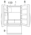
도 1은 본 발명의 실시예에 의한 제빙기가 설치된 냉장고를 나타내는 도면이 도시되어 있고, 도 2에는 본 발명의 일실시예에 따른 제빙기의 사시도가 도시되어 있다.1 is a view showing a refrigerator in which an ice maker according to an embodiment of the present invention is installed, and FIG. 2 is a perspective view of an ice maker according to an embodiment of the present invention.
도 1 내지 도 2를 참조하면, 본 발명의 실시예에 의한 냉장고(1)는 제빙기(100)를 포함할 수 있다.1 to 2, the
냉장고(1)는 전면이 개구된 저장실을 형성하는 캐비닛과, 상기 저장실의 개구된 전면을 개폐하는 적어도 하나의 도어(8, 9)를 포함할 수 있다.The
상기 저장실은, 식품을 냉장 상태로 저장하는 냉장실과, 식품을 냉동 상태로 저장하는 냉동실 중 적어도 하나를 포함할 수 있다. 본 실시예의 냉장고(1)는 상기 냉장실 및 상기 냉동실을 모두 포함하는 것으로 예시한 것으로서, 상기 냉장실이 상기 냉동실의 상측에 구비될 수 있다.The storage compartment may include at least one of a refrigerating compartment storing food in a refrigerated state and a freezing compartment storing food in a frozen state. The
도어(8, 9)는, 상기 냉장실을 개폐하는 냉장실 도어(8)와, 상기 냉동실을 개폐하는 냉동실 도어(9)를 포함할 수 있다. 냉장실 도어(8)는 서로 좌우로 배치된 두 개로 구비되어, 좌측 냉장실 도어(8)는 상기 냉장실의 일부인 좌측을 개폐할 수 있고, 우측 냉장실 도어(8)는 상기 냉장실의 나머지부인 우측을 개폐할 수 있다.The
제빙기(100)는 상기 냉장실 및 상기 냉동실 중 적어도 하나에 설치될 수 있다. 본 실시예의 냉장고(1)는 상기 냉장실의 좌측 상부에 제빙기(100)가 설치될 수 있다.The
제빙기(100)는 냉장고(1)로부터 제빙수를 공급받을 수 있고, 냉장고(1)의 냉동사이클로부터 상기 저장실로 공급되는 냉기에 의해 상기 제빙수를 얼음으로 변하게 하여서, 상기 얼음을 제조할 수 있다.The
이러한 제빙기(100)는 케이스(10), 제어박스(20), 순환팬(200), 개구부(310)가 형성된 유로 커버(320), 아이스 트레이(102) 및 드레인 플레이트(400)를 포함하여 구성되어 있다. 본 실시예에서 설명하기 위한 예로써 도 2에 도시를 한 것이므로, 이제 한정되지는 않고 얼음이 제조된 후에 얼음이 이동되어지는 저장부 및 저장부에 설치된 어거모터와 스크류, 아이스트레이(102)에 제빙수를 공급하는 급수부 등의 구성은 도시를 생략하였다.The
본 발명에 따른 제빙기(100)에서는 제어박스(20) 측에 송풍팬(200)이 위치되어 있다. 특히, 순환팬(200)은 제어박스(20)의 일측 하단부에 형성되되, 소정의 경사를 가지는 형태로 형성되어 있으며, 이에 대해서는 하기에서 도면을 참조하여 보다 상세히 설명한다. In the
송풍팬(200)의 구동에 의해 제빙실(100) 내의 공기는 순환될 수 있다. 제빙실(100) 내의 공기는 열교환을 통해 상온보다 저온상태일 수 있다. 상기 저온상태의 공기가 아이스 트레이(102) 주변에서 이동되며 아이스 트레이의 온도를 저하시킬 수 있고 저하된 아이스 트레이(102)의 온도에 의해 아이스 트레이(102)에 제공된 제빙수는 얼음상태로 될 수 있다. 물론, 아이스 트레이(102)에는 냉각부(120)가 접촉되도록 배치될 수 있다. 냉각부(120)는 냉매가 내부에서 유동될 수 있는 파이프 등이 될 수 있다. 상기 파이프와 아이스 트레이(102)의 접촉된 배치에 의해 아이스 트레이(102)는 영하의 온도를 유지하거나 영하의 온도로 냉각될 수 있다.The air in the
한편, 냉각된 제빙수는 얼음상태가 되는데, 얼음은 이빙이 될 수 있다. 이빙을 위해 아이스 트레이(102)가 트위스트 되거나 이젝터(30)의 회전이 될 수 있는데 본 실시예는 이젝터(30)의 회전에 의해 이빙되는 금속재의 아이스 트레이(102)일 수 있다. 물론 폴리프로필렌을 포함한 소재일수도 있다.Meanwhile, the cooled ice-making water is in an ice state, and the ice may be ice. The
냉장고(1)의 상기 저장실에는 후술할 아이스 박스(2)가 설치될 수 있다. 아이스 박스(2)는 제빙기(100)의 하측에 배치될 수 있다. 아이스 박스(2)는 상측이 개구된 통형상으로 형성될 수 있다. 제빙기(100)에서 제빙된 얼음은 제빙기(100)로부터 아이스 박스(2)로 이빙되어, 아이스 박스(2) 내에 수용되어 저장될 수 있다.An
아이스 박스(2) 내에는 오거(Auger)가 배치될 수 있다. 상기 오거는 아이스 박스(2)에 둘레방향으로 회전 가능하게 설치될 수 있다. 상기 오거의 양단은 각각 아이스 박스(2)의 양면에 회전 가능하게 결합될 수 있다. 상기 오거의 외주면에는 나선홈이 형성될 수 있다. 상기 오거는 회전 시 상기 나선홈을 통해 아이스 박스(2) 내에 저장된 얼음을 아이스 박스(2)의 외부로 이송시킬 수 있다. 상기 오거는 아이스 박스(2)의 일측에 설치된 오거모터의 구동력에 의해 회전될 수 있다.An auger may be disposed in the
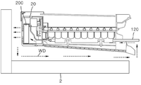
도 3 내지 도 4는 본 발명의 일실시예에 따른 제빙기의 단면도 및 부분 사시도가 모식적으로 도시되어 있다.3 to 4 are schematic sectional views and partial perspective views of an ice maker according to an embodiment of the present invention.
도 3 내지 도 4를 도 2와 함께 참조하면, 본 발명에 따른 제빙기(100)는 냉각부 및 히터부 중 하나 이상을 포함하는 열교환부와 열교환이 수행되는 제빙기(100)는 제어박스(20), 제어박스(20)의 일측으로부터 연장된 아이스 트레이(102), 상기 열교환부의 열교환에 의해 형성되어 낙하되는 수분을 받아 일측으로 흘려보내는 드레인 플레이트(400), 아이스 트레이(102)의 일면에 공기흐름(WD)을 발생시키고 제어박스(20)의 일측에 위치되는 순환팬(200)을 포함하여 구성되어 있다.Referring to FIGS. 3 to 4 together with FIG. 2, the
또는, 냉각부 및 히터부 중 하나 이상을 포함하는 열교환부와 열교환이 수행되는 제빙기(100)는 제어박스(20); 제어박스(20)의 일측으로부터 연장된 아이스 트레이(102), 상기 열교환부의 열교환에 의해 형성되어 낙하되는 수분을 받아 일측으로 흘려보내는 드레인 플레이트(400), 아이스 트레이(102)의 일면에 공기흐름(WD)을 발생시키고 제어박스(20)의 일측에 위치되는 순환팬(200) 및 순환팬(200)에 의해 발생되는 공기흐름(WD)에 방향성을 형성시키고, 낙하되는 수분이 드레인 플레이트(400) 측으로 전달될 수 있도록 수분이 배출될 수 있게 적어도 일부가 통공된 개구부(310)가 마련되는 유로 커버(320)를 포함하여 구성되어 있다.Alternatively, the
개구부(310)는 복수개 마련될 수 있으며, 순환팬(200)의 동작시에 압력차로 인한 공기의 유동을 도모할 수 있고, 온도차에 의해 발생한 수분이 결집되어 낙하되는 물방울을 드레인 플레이트(400)로 배출할 수 있다. 물방울의 배수를 위해 유로 커버(320)의 일부는 젖을 수 있는데 순환팬(200)의 동작시에 공기의 유동에 의해 젖은 부분이 건조될 수 있다.A plurality of openings 310 may be provided, and the flow of air due to a pressure difference during operation of the
제어박스(20) 측에 순환팬(200)이 지면에 대해서 하방 경사지도록 위치되고, 순환팬(200)으로부터 발생한 공기흐름(WD)이 순환팬(200)을 통해 자연스럽게 순환되도록 구성되어 있다. 상기 공기흐름(WD)은 순환팬(200)이 제빙기(100)의 외측방향으로 형성되도록 동작될 수 있다. 즉, 제어박스(20) 측에 경사지게 위치된 순환팬(200)의 회전에 의해 제빙기(100) 내에서 유동하는 냉기가 원활하게 순환팬(200)이 형성된 제어박스(20) 측으로 효과적으로 흡입되도록 함으로써, 유로 커버(320)를 따라 아이스 트레이(102)의 저면부를 스쳐 지나가는 상기 냉기가 순환팬(200)을 통해 일측으로 배출되어 다시 제빙기(100) 내부로 회기 되어 순환될 수 있다. 이러한 공기흐름(WD)은 제빙실의 내기순환을 유발시키고 열교환에 의해 저온의 냉기가 아이스 트레이(102)로 이동되면서 제빙효율을 증가시킬 수 있다.On the
여기서, 본 발명에서 제시하는 도면에는 순환팬(200)이 지면에 대해서 하측 방향으로 대략 45도의 경사를 가지고 형성된 구조이나, 순환 효율이 향상될 수 있는 구조이면 이에 한정되지 않고 다양한 각도의 경사도를 갖도록 구성될 수 있음은 물론이다.Here, in the drawings presented in the present invention, the
본 발명에 따르면, 종래에는 순환팬(200)이 아이스 트레이(102)의 외측, 즉 제어박스(20)가 일측에 형성된 아이스 트레이(102)의 타측 부위에 배치되어 제빙기(100) 내에서 발생되는 공기를 송풍하는 구조로 열교환이 이루어지는 구조임에 반하여, 본 발명에 따른 순환팬(200)은 일측으로 돌출된 형태로 하방 경사지도록 형성시킴으로써, 순환 효율을 극대화하면서 냉기의 유로가 최적화되고 공기 흡입 공간을 확보할 수 있도록 형성시킨 구조에 특징이 있다. According to the present invention, conventionally, the
나아가, 본 발명에 따른 순환팬(200)은 소정의 각도로 하방 경사지도록 형성시킴으로써, 순환팬(200)의 팬그릴부(미도시)에 맺힌 물방울의 낙수에 의한 제어박스(20) 내의 물방울 유입을 방지할 수 있다.Furthermore, the
한편, 열교환부는 히터부(110) 및 냉각부(120) 중 하나 이상을 포함할 수 있는데 적어도 하나는 아이스 트레이(102) 내에 삽입 배치될 수 있다. 삽입 배치를 위해 아이스 트레이(102) 제조시에 삽입되어 사출 성형될 수 있다.Meanwhile, the heat exchange unit may include one or more of the
드레인 플레이트(400)는 아이스 트레이(102) 측으로 연장된 리브를 포함할 수 있다. 상기 리브는 유로 커버(320)를 아이스 트레이(102) 측으로 가압할 수 있다. 이러한 가압은 상기 리브가 가압할 수 있는 위치에 배치되어 기 결정된 높이까지 위치될 수 있고 상기 기 결정된 높이에 의해 유로 커버(320)가 아이스 트레이(102)를 탄성적으로 지지하는 구조가 될 수 있다. 여기서 아이스 트레이(102)를 탄성적으로 직접 지지할 수도 있고, 열교환부를 개재하여 열교환부를 통해 간접적으로 지지할 수 있다.The
다른 예로는 드레인 플레이트(400)가 아이스 트레이(102) 측으로 연장된 리브를 포함하고, 열교환부는 상기 리브에 의해 가압되어 상기 아이스 트레이(102)에 밀착될 수 있다. 즉, 드레인 플레이트(400)로부터 연장된 상기 리브에 의해 열교환부가 가압될 수 있다. 드레인 플레이트(400)로부터 연장된 리브는 유로 커버(320)를 관통하여 아이스 트레이(102) 측으로 연장될 수 있다. 연장된 상기 관통은 유로 커버(320)에 형성된 개구부(310)를 통해 이루어질 수 있다. 개구부(310)는 하나 이상이 마련될 수 있다.As another example, the
또 다른 예로서 드레인 플레이트(400)의 일측에는 별도의 독립적인 판상의 가압부재(미도시)가 구성될 수 있다. 상기 가압부재는 금속재로 형성될 수 있다. 상기 가압부재에는 복수의 배수 홀이 구비되어 아이스 트레이(102)로부터 낙하하는 수분을 받아 배출할 수 있다. 상기 가압부재는 일측방에서 탄성적으로 가압하여 아이스 플레이트(102) 측으로 밀착되도록 탄성부재(미도시)가 형성될 수 있다.As another example, a separate independent plate-shaped pressing member (not shown) may be configured at one side of the
또, 히터부(110)는 면상히터일 수 있다. 면상히터와 아이스 트레이(102)의 저부측 표면과 면접촉을 통해 열전달을 할 수 있고, 상기 열전달에 의해 이빙이 이루어질 수 있다. 제빙기는 다른 하나의 히터를 더 포함할 수 있다. 가열 냉각을 반복하는 과정에서 발생한 수분이 아이스 트레이(102)의 저부에 맺혀 하방으로 떨어질 수 있고, 떨어진 물방울은 드레인 플레이트(400)에 도달할 수 있다. 드레인 플레이트(400)에 도달한 물방울은 제빙실 내부 환경에 의해 결빙될 수 있는데, 결빙이 누적되면 배수목적을 상실할 수 있으므로 결빙가능성이 있는 위치에 히터의 열을 전달할 수 있다. 상기 히터는 해빙히터(미도시)이며, 해빙을 위해 드레인 플레이트(400) 내측에 위치될 수 있다.In addition, the
드레인 플레이트(400)는 표면에 결빙을 방지하는 상기 해빙히터를 더 포함하고, 상기 해빙히터 및 히터부(110)는 직렬 및 병렬 중 하나 이상으로 전기적인 연결이 될 수 있다. 히터부(110) 및 상기 해빙히터는 서로 전기적으로 연결될 수 있는데, 직렬 및 병렬 중 하나 이상의 방식을 통해 연결될 수 있다. 히터부(110) 및 상기 해빙히터는 각각이 복수 개 마련될 수 있기 때문이다.The
제어박스(20)는 캠 회전에 의해 동작되는 만빙레버(101)와 연결될 수 있다. 이러한 경우에는 한 싸이클의 동작 중에 만빙레버(101)의 동작이 개입되어 있어 제빙과정이 기구적으로 연동될 수 있는 것이다. 또한, 만빙레버(101)는 적외선 센서의 감지여부에 의해 제어될 수 있다. 적외선 센서의 감지 여부에 의해 제어되는 경우는 정기적으로 동작을 유도하거나 적외선 센서영역에 만빙레버(101)의 감지여부 감지 시간 등의 조건의 조합에 의해 선택적으로 결정될 수 있다.The
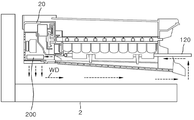
도 5 내지 도 6에는 본 발명의 다른 실시예에 따른 제빙기의 단면도 및 사시도가 도시되어 있고, 도 7에는 본 발명의 또 다른 실시예에 따른 제빙기의 단면도가 모식적으로 도시되어 있다.5 to 6 are cross-sectional views and perspective views of an ice maker according to another embodiment of the present invention, and FIG. 7 is a schematic cross-sectional view of an ice maker according to another embodiment of the present invention.
도 5 내지 도 7을 참조하되 전술한 실시예와 중복되는 부분에 대한 설명은 생략한다. 전술한 실시예와 비교하여, 도 5에 도시된 바와 같이, 송풍팬(200)이 제어박스(20)에 수납된 상태로 좌측 측면 부위에 형성되되, 지면과 평행한 방향으로 형성되어 있을 수 있다. 또는 도 7에 도시된 바와 같이, 송풍팬(200)이 제어박스(20)의 하면 부위, 즉 지면 방향으로 형성될 수 있다.5 to 7 but descriptions of parts overlapping with the above-described embodiments are omitted. Compared to the above-described embodiment, as shown in FIG. 5, the blowing
이상, 본 발명에 따른 제빙기 및 이를 포함하는 냉장고의 일 실시예를 첨부된 도면을 참조하여 상세하게 설명하였다. 그러나, 본 발명의 실시예가 반드시 상술한 일 실시예에 의하여 한정되는 것은 아니고, 본 발명이 속하는 기술분야에서 통상의 지식을 가진 자에 의한 다양한 변형 및 균등한 범위에서의 실시가 가능함은 당연하다고 할 것이다. 그러므로, 본 발명의 진정한 권리범위는 후술하는 청구범위에 의하여 정해진다고 할 것이다.Or more, with reference to the accompanying drawings, an embodiment of an ice machine according to the present invention and a refrigerator including the same has been described in detail. However, the embodiments of the present invention are not necessarily limited to the above-described embodiments, and it is natural that various modifications and equivalent implementations by a person skilled in the art to which the present invention pertains are possible. will be. Therefore, the true scope of the present invention will be defined by the claims below.
1: 냉장고
2: 아이스 박스
10: 케이스
20: 제어박스
30 : 이젝터
100: 제빙기
102: 아이스 트레이
110: 히터부
120: 냉각부
200: 순환팬
310: 개구부
320: 유로 커버1: refrigerator 2: ice box
10: case 20: control box
30: ejector 100: ice machine
102: ice tray 110: heater unit
120: cooling unit 200: circulation fan
310: opening 320: Euro cover
Claims (14)
제어박스;
상기 제어박스 일측으로 연장되고 제빙홈이 형성된 아이스 트레이;
상기 제어박스에 결합되고 상기 아이스 트레이로부터 낙하하는 수분을 받아 배출하는 드레인 플레이트; 및
상기 아이스 트레이의 일면에 공기 흐름을 발생시키고, 상기 제어박스의 일측에 위치되며 상기 아이스 트레이의 일단으로부터 제빙실 내의 공기가 유입되도록 하는 순환팬;을 포함하고,
상기 순환팬은 토출 방향이 수평, 수직 또는 소정의 경사를 갖고 배치되는 순환팬;을 포함하는 제빙기.In an ice machine in which heat exchange is performed with a heat exchange unit including at least one of a cooling unit and a heater unit,
Control box;
An ice tray extending to one side of the control box and having an ice-making groove;
A drain plate coupled to the control box and receiving and discharging water falling from the ice tray; And
It includes; a circulation fan that generates air flow on one surface of the ice tray, and is located on one side of the control box to allow air in the ice making chamber to flow from one end of the ice tray;
The circulating fan includes a circulating fan in which the discharge direction is horizontally, vertically or with a predetermined inclination.
상기 순환팬은 지면에 대해서 직하방 방향으로 경사지게 형성되는 제빙기.According to claim 1,
The circulating fan is an ice machine that is inclined in a downward direction with respect to the ground.
상기 순환팬은 직하방으로 0 내지 90도 범위의 경사를 갖는 제빙기.According to claim 2,
The circulation fan is an ice maker having a slope in the range of 0 to 90 degrees directly downward.
상기 제어박스에는 상기 순환팬에 의하여 이동되는 공기가 배출되도록 토출되는 부위에 통공이 형성되어 있는 제빙기.According to claim 1,
In the control box, an ice machine having a through hole is formed in a discharged portion so that air moved by the circulation fan is discharged.
상기 순환팬은 상기 열교환부로부터 직접 냉기를 흡입하는 제빙기.According to claim 1,
The circulation fan is an ice maker that sucks cold air directly from the heat exchanger.
제어박스;
상기 제어박스 일측으로 연장되고 제빙홈이 형성된 아이스 트레이;
상기 제어박스에 결합되고 상기 아이스 트레이로부터 낙하하는 수분을 받아 배출하는 드레인 플레이트;
상기 아이스 트레이의 일면에 공기 흐름을 발생시키고, 상기 제어박스의 일측에 위치되며 상기 아이스 트레이의 일단으로부터 제빙실 내의 공기가 유입되도록 하고 수평, 수직 또는 소정의 경사를 갖고 배치되는 순환팬; 및
상기 순환팬에 의해 발생되는 상기 공기흐름에 방향성을 형성시키고, 낙하되는 상기 수분이 상기 드레인 플레이트 측으로 전달될 수 있도록 상기 수분이 배출될 수 있게 개구된 개구부가 마련되는 유로 커버;를 더 포함하는 제빙기.In an ice machine in which heat exchange is performed with a heat exchange unit including at least one of a cooling unit and a heater unit,
Control box;
An ice tray extending to one side of the control box and having an ice-making groove;
A drain plate coupled to the control box and receiving and discharging water falling from the ice tray;
A circulation fan which generates air flow on one surface of the ice tray, is located at one side of the control box, and allows air in the ice making room to flow in from the one end of the ice tray and has a horizontal, vertical or predetermined inclination; And
An ice machine further comprising; a flow path cover provided with an opening so as to form directionality in the air flow generated by the circulation fan and to allow the moisture to be discharged so that the dropped water can be delivered to the drain plate side. .
상기 열교환부는 상기 아이스 트레이와 유로 커버 사이에 형성되는 제빙기.The method of claim 6,
The heat exchange unit is an ice maker formed between the ice tray and the flow path cover.
상기 드레인 플레이트는 상기 아이스 트레이 측으로 연장된 리브를 포함하고,
상기 열교환부는 상기 리브에 의해 가압되어 상기 아이스 트레이에 밀착되는 제빙기.According to claim 1,
The drain plate includes a rib extending toward the ice tray,
The heat exchange unit is pressurized by the ribs and the ice maker is in close contact with the ice tray.
상기 드레인 플레이트는 표면에 결빙을 방지하는 해빙히터를 더 포함하고,
상기 해빙히터는 PET(Polyethylene), PI(Polyimide), 스테인리스강, 알루미늄 및 카본 중 하나 이상을 포함하는 제빙기.According to claim 1,
The drain plate further includes a thawing heater to prevent freezing on the surface,
The thawing heater is an ice maker comprising at least one of PET (Polyethylene), PI (Polyimide), stainless steel, aluminum and carbon.
상기 제어박스는 캠 회전에 의해 동작되는 만빙레버와 연결되는 제빙기.According to claim 1,
The control box is an ice maker connected to a full ice lever operated by cam rotation.
상기 만빙레버는 적외선 센서의 감지여부에 의해 제어되는 제빙기.The method of claim 10,
The ice-making lever is controlled by the detection of the infrared sensor.
상기 냉각부는 아이스 트레이에 삽입 배치되는 것을 제빙기.The method according to claim 1 or 6,
The ice-making unit is disposed to be inserted into the ice tray.
상기 히터부는 면상히터인 제빙기.The method according to claim 1 or 6,
The heater is an ice maker that is a surface heater.
Applications Claiming Priority (2)
| Application Number | Priority Date | Filing Date | Title |
|---|---|---|---|
| KR1020190001878 | 2019-01-07 | ||
| KR1020190001878A KR20190008964A (en) | 2019-01-07 | 2019-01-07 | Ice maker and refrigerator comprising the same |
Publications (1)
| Publication Number | Publication Date |
|---|---|
| KR20200085641A true KR20200085641A (en) | 2020-07-15 |
Family
ID=65280468
Family Applications (2)
| Application Number | Title | Priority Date | Filing Date |
|---|---|---|---|
| KR1020190001878A KR20190008964A (en) | 2019-01-07 | 2019-01-07 | Ice maker and refrigerator comprising the same |
| KR1020190157422A KR20200085641A (en) | 2019-01-07 | 2019-11-29 | Ice maker and refrigerator including the same |
Family Applications Before (1)
| Application Number | Title | Priority Date | Filing Date |
|---|---|---|---|
| KR1020190001878A KR20190008964A (en) | 2019-01-07 | 2019-01-07 | Ice maker and refrigerator comprising the same |
Country Status (1)
| Country | Link |
|---|---|
| KR (2) | KR20190008964A (en) |
Cited By (1)
| Publication number | Priority date | Publication date | Assignee | Title |
|---|---|---|---|---|
| WO2022010256A1 (en) | 2020-07-10 | 2022-01-13 | 주식회사 엘지에너지솔루션 | Secondary battery including gas discharging part for gas discharge and method for manufacturing secondary battery |
Families Citing this family (1)
| Publication number | Priority date | Publication date | Assignee | Title |
|---|---|---|---|---|
| KR20190012238A (en) * | 2019-01-15 | 2019-02-08 | 주식회사 대창 | Ice maker, ice maker module and refrigerator comprising the ice maker module |
Citations (1)
| Publication number | Priority date | Publication date | Assignee | Title |
|---|---|---|---|---|
| KR20130078532A (en) | 2011-12-30 | 2013-07-10 | 삼성전자주식회사 | Refrigerator |
-
2019
- 2019-01-07 KR KR1020190001878A patent/KR20190008964A/en unknown
- 2019-11-29 KR KR1020190157422A patent/KR20200085641A/en unknown
Patent Citations (1)
| Publication number | Priority date | Publication date | Assignee | Title |
|---|---|---|---|---|
| KR20130078532A (en) | 2011-12-30 | 2013-07-10 | 삼성전자주식회사 | Refrigerator |
Cited By (1)
| Publication number | Priority date | Publication date | Assignee | Title |
|---|---|---|---|---|
| WO2022010256A1 (en) | 2020-07-10 | 2022-01-13 | 주식회사 엘지에너지솔루션 | Secondary battery including gas discharging part for gas discharge and method for manufacturing secondary battery |
Also Published As
| Publication number | Publication date |
|---|---|
| KR20190008964A (en) | 2019-01-25 |
Similar Documents
| Publication | Publication Date | Title |
|---|---|---|
| EP3062048B1 (en) | Refrigerator | |
| US8973391B2 (en) | Refrigerator | |
| KR101658674B1 (en) | Ice storing apparatus and control method therof | |
| EP3059526A1 (en) | Ice-making tray and refrigerator comprising same | |
| CN101960241B (en) | Water funnel and ice maker for refrigerator having the same | |
| KR20120124324A (en) | Ice making apparatus and refrigerator having the same | |
| US9423166B2 (en) | Refrigerator | |
| KR20100092168A (en) | Ice maker and refrigerator having the same | |
| KR20120012230A (en) | Refrigerator with ice dispenser | |
| MX2010005732A (en) | Ice-making unit and refrigerator having the same. | |
| US11585584B2 (en) | Refrigerator and control method thereof | |
| US8281611B2 (en) | Icemaker for a refrigerator | |
| KR20200085641A (en) | Ice maker and refrigerator including the same | |
| KR20190012238A (en) | Ice maker, ice maker module and refrigerator comprising the ice maker module | |
| KR102280935B1 (en) | Refrigerator and manufacturing method of auger for refrigerator | |
| KR101721760B1 (en) | Ice maker and refrigerator having the same | |
| CN106257172B (en) | Ice pan device and method | |
| KR20100113207A (en) | A refrigerator | |
| WO2018163332A1 (en) | Automatic ice maker and freezer refrigerator | |
| US20220282904A1 (en) | Refrigerator | |
| KR101519877B1 (en) | Ice maker and refrigerator having the same | |
| KR20230053107A (en) | Ice maker and refrigerator including the same | |
| KR20210051712A (en) | Ice maker and refrigerator including the same | |
| KR101596502B1 (en) | Refrigerator | |
| KR20210116891A (en) | Ice maker and refrigerator including the same |