KR20200085329A - Thermostatic valve - Google Patents
Thermostatic valve Download PDFInfo
- Publication number
- KR20200085329A KR20200085329A KR1020207016769A KR20207016769A KR20200085329A KR 20200085329 A KR20200085329 A KR 20200085329A KR 1020207016769 A KR1020207016769 A KR 1020207016769A KR 20207016769 A KR20207016769 A KR 20207016769A KR 20200085329 A KR20200085329 A KR 20200085329A
- Authority
- KR
- South Korea
- Prior art keywords
- valve
- valve port
- port
- memory spring
- outlet
- Prior art date
Links
Images


Classifications
-
- G—PHYSICS
- G05—CONTROLLING; REGULATING
- G05D—SYSTEMS FOR CONTROLLING OR REGULATING NON-ELECTRIC VARIABLES
- G05D23/00—Control of temperature
- G05D23/01—Control of temperature without auxiliary power
- G05D23/02—Control of temperature without auxiliary power with sensing element expanding and contracting in response to changes of temperature
-
- F—MECHANICAL ENGINEERING; LIGHTING; HEATING; WEAPONS; BLASTING
- F16—ENGINEERING ELEMENTS AND UNITS; GENERAL MEASURES FOR PRODUCING AND MAINTAINING EFFECTIVE FUNCTIONING OF MACHINES OR INSTALLATIONS; THERMAL INSULATION IN GENERAL
- F16K—VALVES; TAPS; COCKS; ACTUATING-FLOATS; DEVICES FOR VENTING OR AERATING
- F16K31/00—Actuating devices; Operating means; Releasing devices
- F16K31/002—Actuating devices; Operating means; Releasing devices actuated by temperature variation
-
- F—MECHANICAL ENGINEERING; LIGHTING; HEATING; WEAPONS; BLASTING
- F01—MACHINES OR ENGINES IN GENERAL; ENGINE PLANTS IN GENERAL; STEAM ENGINES
- F01P—COOLING OF MACHINES OR ENGINES IN GENERAL; COOLING OF INTERNAL-COMBUSTION ENGINES
- F01P7/00—Controlling of coolant flow
- F01P7/14—Controlling of coolant flow the coolant being liquid
- F01P7/16—Controlling of coolant flow the coolant being liquid by thermostatic control
-
- F—MECHANICAL ENGINEERING; LIGHTING; HEATING; WEAPONS; BLASTING
- F16—ENGINEERING ELEMENTS AND UNITS; GENERAL MEASURES FOR PRODUCING AND MAINTAINING EFFECTIVE FUNCTIONING OF MACHINES OR INSTALLATIONS; THERMAL INSULATION IN GENERAL
- F16H—GEARING
- F16H57/00—General details of gearing
- F16H57/04—Features relating to lubrication or cooling or heating
- F16H57/0412—Cooling or heating; Control of temperature
- F16H57/0413—Controlled cooling or heating of lubricant; Temperature control therefor
-
- F—MECHANICAL ENGINEERING; LIGHTING; HEATING; WEAPONS; BLASTING
- F16—ENGINEERING ELEMENTS AND UNITS; GENERAL MEASURES FOR PRODUCING AND MAINTAINING EFFECTIVE FUNCTIONING OF MACHINES OR INSTALLATIONS; THERMAL INSULATION IN GENERAL
- F16K—VALVES; TAPS; COCKS; ACTUATING-FLOATS; DEVICES FOR VENTING OR AERATING
- F16K11/00—Multiple-way valves, e.g. mixing valves; Pipe fittings incorporating such valves
- F16K11/02—Multiple-way valves, e.g. mixing valves; Pipe fittings incorporating such valves with all movable sealing faces moving as one unit
-
- F—MECHANICAL ENGINEERING; LIGHTING; HEATING; WEAPONS; BLASTING
- F01—MACHINES OR ENGINES IN GENERAL; ENGINE PLANTS IN GENERAL; STEAM ENGINES
- F01P—COOLING OF MACHINES OR ENGINES IN GENERAL; COOLING OF INTERNAL-COMBUSTION ENGINES
- F01P11/00—Component parts, details, or accessories not provided for in, or of interest apart from, groups F01P1/00 - F01P9/00
- F01P11/08—Arrangements of lubricant coolers
-
- F—MECHANICAL ENGINEERING; LIGHTING; HEATING; WEAPONS; BLASTING
- F01—MACHINES OR ENGINES IN GENERAL; ENGINE PLANTS IN GENERAL; STEAM ENGINES
- F01P—COOLING OF MACHINES OR ENGINES IN GENERAL; COOLING OF INTERNAL-COMBUSTION ENGINES
- F01P2060/00—Cooling circuits using auxiliaries
- F01P2060/04—Lubricant cooler
- F01P2060/045—Lubricant cooler for transmissions
-
- F—MECHANICAL ENGINEERING; LIGHTING; HEATING; WEAPONS; BLASTING
- F01—MACHINES OR ENGINES IN GENERAL; ENGINE PLANTS IN GENERAL; STEAM ENGINES
- F01P—COOLING OF MACHINES OR ENGINES IN GENERAL; COOLING OF INTERNAL-COMBUSTION ENGINES
- F01P2070/00—Details
- F01P2070/02—Details using shape memory alloys
Abstract
단부 캡(30), 밸브 본체(10) 및 밸브 본체의 밸브 챔버(10a)에 위치된 밸브 코어(40)를 포함하는 자동온도조절 밸브가 개시되며, 자동온도조절 밸브는 제1 유출구(101), 제2 유출구(104), 밸브 챔버와 연통하는 제1 유입구(103), 밸브 챔버 및 제2 유출구와 연통하는 제1 밸브 포트(B), 그리고 밸브 챔버 및 제1 유출구와 연통하는 제2 밸브 포트(A)를 가지고, 밸브 챔버에는 리턴 스프링(202) 및 메모리 스프링(201)이 추가로 구비된다. 온도가 특정 값으로 상승하면, 메모리 스프링은 탄성력을 생성하여 밸브 코어를 복귀력을 극복하며 이동하도록 구동함으로써 제1 밸브 포트를 닫는다. 밸브 본체 또는 밸브 코어 또는 단부 캡에는 초기 위치 및 작동 위치가 구비되며, 메모리 스프링의 적어도 하나의 단부는 초기 위치에 위치된다. 온도가 특정 값으로 상승하면, 메모리 스프링이 변형되어 후단부가 초기 위치에서 분리되어 작동 위치에 유지될 수 있다. 메모리 스프링은 응답시간이 더 빠르며 즉시 다른 유로로 전환할 수 있다. 자동온도조절 밸브는 부피가 작으며, 초기 위치 및 작동 위치를 제공함으로써, 관련 장치는 초기 상태에서 제1 유출구를 통해 매체로 채워질 수 있다.Disclosed is a thermostatic valve comprising an end cap 30, a valve body 10 and a valve core 40 located in the valve chamber 10a of the valve body, the thermostatic valve comprising a first outlet 101 , A second outlet 104, a first inlet 103 communicating with the valve chamber, a first valve port B communicating with the valve chamber and a second outlet, and a second valve communicating with the valve chamber and the first outlet With the port A, the valve chamber is further equipped with a return spring 202 and a memory spring 201. When the temperature rises to a certain value, the memory spring creates an elastic force to close the first valve port by driving the valve core to move over the return force. The valve body or valve core or end cap is provided with an initial position and an operating position, and at least one end of the memory spring is located in the initial position. When the temperature rises to a certain value, the memory spring is deformed so that the rear end can be separated from the initial position and held in the working position. Memory springs have faster response times and can instantly switch to another channel. The thermostatic valve is small in volume, and by providing an initial position and an operating position, the associated device can be filled with media through the first outlet in the initial state.
Description
본원은 밸브 본체의 기술 분야, 특히 자동온도조절 밸브에 관한 것이다.The present application relates to the technical field of valve bodies, in particular to thermostatic valves.
윤활유는 윤활 및 냉각의 기능을 수행할 수 있는 차량의 변속기에 수용되어야 하며, 윤활유는 적절한 작동 온도에서 제어되어야 한다.The lubricant must be accommodated in the transmission of the vehicle capable of performing the functions of lubrication and cooling, and the lubricant must be controlled at an appropriate operating temperature.
변속기에서 윤활유의 온도가 높을 때, 윤활유는 외부 냉각장치에 의해 냉각될 수 있다. 냉각장치는 냉각수 또는 냉매를 사용하여 고온의 윤활유를 냉각시키는 열교환기를 포함함으로써, 변속기의 윤활유를 특정 작동 온도 범위 내로 유지시키는 목적을 달성한다. 윤활유의 온도가 낮으면, 윤활유는 냉각장치를 통과하지 않는다. 즉, 변속기의 윤활유가 유출될 때 두 개의 유로가 있는데, 하나의 유로는 냉각장치를 통과하고, 다른 하나는 냉각장치를 통과하지 않는다.When the temperature of the lubricant in the transmission is high, the lubricant can be cooled by an external cooling device. The cooling device achieves the purpose of maintaining the transmission's lubricating oil within a specific operating temperature range by including a heat exchanger that cools the hot lubricating oil using cooling water or a refrigerant. When the temperature of the lubricant is low, the lubricant does not pass through the cooling device. That is, there are two flow paths when the lubricant oil of the transmission flows out, one flow path passes through the cooling device and the other does not pass through the cooling device.
현재, 상기 2 개의 유로의 전환은 자동온도조절 밸브를 통해 수행된다. 자동온도조절 밸브에는 열 액추에이터와 스프링이 구비된다. 열 액추에이터는 감 열성 물질에 의해 감지된 유체의 온도에 따라 열적으로 팽창 및 수축된다. 열팽창 중에는, 스프링에 힘이 전달되어 냉각장치를 통과하는 유로가 개방되며, 냉각수축 중에는, 스프링이 리셋되어 냉각장치를 통과하는 유로가 우회된다.Currently, the switching of the two flow paths is performed through a thermostatic valve. The thermostatic valve is equipped with a thermal actuator and a spring. The thermal actuator expands and contracts thermally according to the temperature of the fluid sensed by the thermosensitive material. During thermal expansion, a force is transmitted to the spring to open the flow passage through the cooling device, and during cooling contraction, the spring is reset to bypass the flow passage through the cooling device.
상기 해결책은 다음과 같은 기술적 문제가 있다.The above solution has the following technical problem.
감열성 물질에 의한 온도 감지로부터 열적 팽창 및 수축 공정, 그 후 스프링에 힘을 가하기까지에 필요한 응답 시간이 있다. 즉, 열 액추에이터의 응답 시간이 길어서, 윤활유 온도의 특정 히스테리시스(hysteresis)를 유발하므로, 변속기의 성능에 영향을 미친다. 또한, 상기 감열성 물질을 포함하는 열 액추에이터는 부피가 크다.There is a response time required from the temperature sensing by the thermosensitive material to the thermal expansion and contraction process, and then applying force to the spring. That is, the response time of the thermal actuator is long, causing a certain hysteresis of the lubricant temperature, thus affecting the performance of the transmission. In addition, the thermal actuator comprising the thermosensitive material is bulky.
온도 제어의 감지 시간을 개선하기 위해 본원에 따라 자동온도조절 밸브가 제공된다.A thermostatic valve according to the present application is provided to improve the sensing time of temperature control.
단부 커버, 밸브 본체 및 상기 밸브 본체의 밸브 캐비티에 위치한 밸브 코어를 포함하는 자동온도조절 밸브가 본원의 기술적 해법에 따라 제공되며, 자동온도조절 밸브는 제1 유출구, 제2 유출구 및 밸브 캐비티와 연통하는 제1 유입구를 가지고, 밸브 본체에는 밸브 캐비티를 제2 유출구와 연통시키도록 구성된 제1 밸브 포트가 추가로 구비되며, 밸브 코어의 이동 중에 밸브 코어는 제1 밸브 포트를 개폐하도록 구성되고,An thermostatic valve comprising an end cover, a valve body and a valve core located in the valve cavity of the valve body is provided in accordance with the technical solutions herein, wherein the thermostatic valve communicates with the first outlet, the second outlet and the valve cavity Having a first inlet, the valve body is further provided with a first valve port configured to communicate the valve cavity with the second outlet, the valve core is configured to open and close the first valve port during movement of the valve core,
밸브 캐비티에는 리턴 스프링 및 메모리 스프링이 추가로 구비되고, 메모리 스프링은 메모리 합금으로 제조되며, 리턴 스프링은 복귀력을 제공하여 밸브 코어가 제1 밸브 포트를 개방하게 하도록 구성되고, 메모리 스프링은 일 단부가 밸브 코어의 일 단부와 접촉하고, 다른 일 단부가 단부 커버와 접촉하며, 온도가 특정 값으로 상승할 때, 메모리 스프링은 탄성력을 발생시켜 밸브 코어를 복귀력에 대항하여 이동하도록 구동함으로써 제1 밸브 포트를 폐쇄하도록 구성되고,The valve cavity is further equipped with a return spring and a memory spring, the memory spring is made of a memory alloy, the return spring is configured to provide a return force so that the valve core opens the first valve port, and the memory spring has one end Is in contact with one end of the valve core, the other end contacts the end cover, and when the temperature rises to a certain value, the memory spring generates elastic force to drive the valve core to move against the return force, thereby Configured to close the valve port,
밸브 코어의 외벽의 적어도 일부는 밸브 캐비티의 내벽과 슬라이딩 결합되고, 제1 유입구는 밸브 본체의 측벽에 구비된다.At least a portion of the outer wall of the valve core is slidingly engaged with the inner wall of the valve cavity, and the first inlet is provided on the side wall of the valve body.
열 액추에이터를 갖는 기술적 해법과 비교하여, 메모리 스프링을 사용하는 해법의 응답 시간이 더 빠르며, 상기 기술적 해법에서는 매체를 다른 유로로 전환하기에 늦지 않게 제1 밸브 포트가 개방될 수 있다. 냉각기와 변속기에 적용하면 변속기의 성능을 향상시킬 수 있다. 또한, 열 액추에이터와 비교하여, 메모리 스프링과 밸브 코어의 조합은 무게가 가볍고 부피가 작다.Compared to the technical solution with a thermal actuator, the response time of the solution using a memory spring is faster, and in the technical solution, the first valve port can be opened not too late to switch the medium to another flow path. When applied to coolers and transmissions, the performance of the transmission can be improved. In addition, compared to thermal actuators, the combination of memory spring and valve core is lighter in weight and smaller in volume.
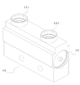
도 1은 본원의 제1 실시예에 따른 자동온도조절 밸브의 구조를 도시한 개략도이고,
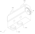
도 2는 도 1의 자동온도조절 밸브를 다른 각도에서 본 개략도로서, 바닥을 도시하며,
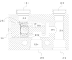
도 3은 도 1의 자동온도조절 밸브의 단면도로서, 제2 밸브 포트가 폐쇄되고 제1 밸브 포트가 개방된 상태를 나타내고,
도 4는 밸브 코어가 우측으로 이동된 후의 도 3의 자동온도조절 밸브의 개략도로서, 제1 밸브 포트가 폐쇄되고 제2 밸브 포트가 개방된 상태를 나타내며,
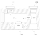
도 5는 도 3의 밸브 본체의 개략도이고,
도 6은 본원의 제2 실시예에 따른 자동온도조절 밸브의 구조를 도시한 단면도로서, 제2 밸브 포트가 폐쇄되고 제1 밸브 포트가 개방된 상태를 나타내며,
도 7은 밸브 코어가 우측으로 이동된 후의 도 6의 자동온도조절 밸브의 개략도로서, 제1 밸브 포트가 폐쇄되고 제2 밸브 포트가 개방된 상태를 나타내고,
도 8은 본원의 제3 실시예에 따른 초기 상태에서의 자동온도조절 밸브의 구조를 도시한 단면도로서, 제1 밸브 포트가 미리 설정된 개방도를 갖고 제2 밸브 포트가 미리 설정된 개방도를 갖는 상태를 나타내며,
도 9는 온도가 특정 값으로 상승하고 메모리 스프링이 변형된 후의 도 8의 자동온도조절 밸브의 개략도로서, 제1 밸브 포트가 폐쇄되고 제2 밸브 포트가 개방된 상태를 나타내고,
도 10은 온도가 특정 값 아래로 떨어지고 메모리 스프링이 특성을 상실한 후의 도 9의 자동온도조절 밸브의 개략도로서, 제1 밸브 포트가 개방되고 제2 밸브 포트가 폐쇄된 상태를 나타내며,
도 11은 도 8의 밸브 코어의 구조를 도시한 개략도이고,
도 12는 본원의 제4 실시예에 따른 초기 상태에서의 자동온도조절 밸브의 구조를 도시한 단면도로서, 제1 밸브 포트가 미리 설정된 개방도를 갖고 제2 밸브 포트가 미리 설정된 개방도를 갖는 상태를 나타내며,
도 13은 온도가 특정 값으로 상승하고 메모리 스프링이 변형된 후의 도 12의 자동온도조절 밸브의 개략도로서, 제1 밸브 포트가 폐쇄되고 제2 밸브 포트가 개방된 상태를 나타내고,
도 14는 온도가 특정 값 아래로 떨어지고 메모리 스프링이 특성을 상실한 후의 도 13의 자동온도조절 밸브의 개략도로서, 제1 밸브 포트가 개방되고 제2 밸브 포트가 폐쇄된 상태를 나타내며,
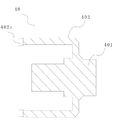
도 15는 도 12의 단부 커버의 구조를 도시한 개략도이고,
도 16은 본원의 제5 실시예에 따른 초기 상태에서의 자동온도조절 밸브의 구조를 도시한 단면도로서, 제1 밸브 포트가 미리 설정된 개방도를 갖고 제2 밸브 포트가 미리 설정된 개방도를 갖는 상태를 나타내며,
도 17은 온도가 특정 값으로 상승하고 메모리 스프링이 변형된 후의 도 16의 자동온도조절 밸브의 개략도로서, 제1 밸브 포트가 폐쇄되고 제2 밸브 포트가 개방된 상태를 나타내고,
도 18은 온도가 특정 값 아래로 떨어지고 메모리 스프링이 특성을 상실한 후의 도 17의 자동온도조절 밸브의 개략도로서, 제1 밸브 포트가 개방되고 제2 밸브 포트가 폐쇄된 상태를 나타내며,
도 19는 본원의 제6 실시예에 따른 자동온도조절 밸브의 구조를 도시한 단면도로서, 제1 밸브 포트가 폐쇄되고 제2 밸브 포트가 개방된 상태를 나타내고,
도 20은 도 19의 밸브 코어의 구조를 도시한 개략도이며,
도 21은 본원의 제7 실시예에 따른 자동온도조절 밸브의 구조를 도시한 단면도로서, 제1 밸브 포트가 폐쇄되고 제2 밸브 포트가 개방된 상태를 나타내고,
도 22는 본원의 제8 실시예에 따른 자동온도조절 밸브의 구조를 도시한 단면도로서, 제1 밸브 포트가 개방되고 제2 밸브 포트가 폐쇄된 상태를 나타내며,
도 23은 온도가 상승하고 메모리 스프링이 변형된 후의 도 22의 자동온도조절 밸브의 개략도로서, 제1 밸브 포트가 폐쇄되고 제2 밸브 포트가 개방된 상태를 나타내고,
도 24는 설치 후 도 22의 단부 커버, 밸브 코어, 리턴 스프링 및 메모리 스프링을 도시한 개략도이며,
도 25는 도 24의 개략사시도이고,
도 26은 본원의 제9 실시예에 따른 자동온도조절 밸브의 구조를 도시한 단면도로서, 제1 밸브 포트(B)가 폐쇄되고 제2 밸브 포트(A)가 개방된 상태를 나타내며,
도 27은 본원의 제10 실시예에 따른 자동온도조절 밸브의 구조를 도시한 단면도로서, 제1 밸브 포트가 개방되고 제2 밸브 포트가 폐쇄된 상태를 나타내고,
도 28은 밸브 코어가 우측으로 이동된 후의 도 27의 자동온도조절 밸브의 개략도로서, 제2 밸브 포트가 개방되고 제1 밸브 포트가 폐쇄된 상태를 나타내며,
도 29는 도 27의 밸브 코어의 개략도이다.1 is a schematic diagram showing the structure of a thermostatic valve according to a first embodiment of the present application,
FIG. 2 is a schematic view of the thermostatic valve of FIG. 1 viewed from a different angle, showing the bottom,
3 is a cross-sectional view of the thermostatic valve of FIG. 1, showing a state in which the second valve port is closed and the first valve port is open;
4 is a schematic view of the thermostatic valve of FIG. 3 after the valve core is moved to the right, showing a state in which the first valve port is closed and the second valve port is open;
5 is a schematic view of the valve body of FIG. 3,
6 is a cross-sectional view showing the structure of a thermostatic valve according to a second embodiment of the present application, showing a state in which the second valve port is closed and the first valve port is opened,
7 is a schematic view of the thermostatic valve of FIG. 6 after the valve core is moved to the right, showing a state in which the first valve port is closed and the second valve port is opened;
8 is a cross-sectional view showing the structure of a thermostatic valve in an initial state according to a third embodiment of the present application, wherein the first valve port has a preset opening degree and the second valve port has a preset opening degree Represents
9 is a schematic diagram of the thermostatic valve of FIG. 8 after the temperature rises to a certain value and the memory spring is deformed, showing a state in which the first valve port is closed and the second valve port is opened;
FIG. 10 is a schematic diagram of the thermostatic valve of FIG. 9 after the temperature drops below a certain value and the memory spring loses its characteristics, showing a state in which the first valve port is opened and the second valve port is closed;
11 is a schematic view showing the structure of the valve core of FIG. 8,
12 is a cross-sectional view showing the structure of a thermostatic valve in an initial state according to a fourth embodiment of the present application, wherein the first valve port has a preset opening degree and the second valve port has a preset opening degree Represents
13 is a schematic diagram of the thermostatic valve of FIG. 12 after the temperature rises to a certain value and the memory spring is deformed, showing the state in which the first valve port is closed and the second valve port is opened;
FIG. 14 is a schematic diagram of the thermostatic valve of FIG. 13 after the temperature drops below a certain value and the memory spring loses its characteristics, showing a state in which the first valve port is opened and the second valve port is closed;
15 is a schematic view showing the structure of the end cover of FIG. 12,
16 is a cross-sectional view showing the structure of a thermostatic valve in an initial state according to a fifth embodiment of the present application, wherein the first valve port has a preset opening degree and the second valve port has a preset opening degree Represents
FIG. 17 is a schematic diagram of the thermostatic valve of FIG. 16 after the temperature rises to a certain value and the memory spring is deformed, showing a state in which the first valve port is closed and the second valve port is opened;
18 is a schematic diagram of the thermostatic valve of FIG. 17 after the temperature drops below a certain value and the memory spring loses its characteristics, showing a state in which the first valve port is opened and the second valve port is closed;
19 is a cross-sectional view showing the structure of the thermostatic valve according to the sixth embodiment of the present application, showing a state in which the first valve port is closed and the second valve port is opened,
20 is a schematic view showing the structure of the valve core of FIG. 19,
21 is a cross-sectional view showing the structure of the thermostatic valve according to the seventh embodiment of the present application, showing a state in which the first valve port is closed and the second valve port is opened,
22 is a cross-sectional view showing the structure of the thermostatic valve according to the eighth embodiment of the present application, showing a state in which the first valve port is opened and the second valve port is closed,
23 is a schematic diagram of the thermostatic valve of FIG. 22 after the temperature rises and the memory spring is deformed, showing a state in which the first valve port is closed and the second valve port is open;
Fig. 24 is a schematic diagram showing the end cover, valve core, return spring and memory spring of Fig. 22 after installation,
25 is a schematic perspective view of FIG. 24,
26 is a cross-sectional view showing the structure of the thermostatic valve according to the ninth embodiment of the present application, showing a state in which the first valve port (B) is closed and the second valve port (A) is opened,
27 is a cross-sectional view showing the structure of the thermostatic valve according to the tenth embodiment of the present application, showing a state in which the first valve port is opened and the second valve port is closed,
28 is a schematic diagram of the thermostatic valve of FIG. 27 after the valve core is moved to the right, showing a state in which the second valve port is opened and the first valve port is closed;
29 is a schematic view of the valve core of FIG. 27;
본원은 2017년 11월 13일에 중국특허청에 출원된 "자동온도조절 밸브"라는 명칭의 중국특허출원 제201711116965.7호 및 2017년 11월 13일에 중국특허청에 출원된 "자동온도조절 밸브"라는 명칭의 중국특허출원 제201711115307.6호에 대한 우선권을 주장하며, 상기 출원들은 그 전체 내용이 본원에 참조로 포함된다.The present application is titled "Automatic Temperature Control Valve", filed with the Chinese Patent Office on November 13, 2017, and the Chinese Patent Application No. 201711116965.7 and the "Automatic Temperature Control Valve" filed with the Chinese Patent Office on November 13, 2017. Claims of Chinese patent application No. 201711115307.6 of the above, the entire contents of which are incorporated herein by reference.
통상의 기술자가 본원의 기술적 해법을 더 잘 이해하도록 하기 위해, 본원은 도면 및 특정 실시예와 함께 아래에서 더 상세히 설명된다.In order for a person skilled in the art to better understand the technical solutions herein, the present application is described in more detail below in conjunction with the drawings and specific embodiments.
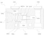
도 1 내지 도 4를 참조하면, 도 1은 본원의 제1 실시예에 따른 자동온도조절 밸브의 구조를 도시한 개략도이고, 도 2는 도 1의 자동온도조절 밸브를 다른 각도에서 본 개략도로서, 바닥을 도시하며, 도 3은 도 1의 자동온도조절 밸브의 단면도로서, 제2 밸브 포트가 폐쇄되고 제1 밸브 포트가 개방된 상태를 나타내고, 도 4는 밸브 코어가 우측으로 이동된 후의 도 3의 자동온도조절 밸브의 개략도로서, 제1 밸브 포트가 폐쇄되고 제2 밸브 포트가 개방된 상태를 나타내며, 도 5는 도 3의 밸브 본체의 개략도이다.1 to 4, FIG. 1 is a schematic view showing the structure of a thermostatic valve according to a first embodiment of the present application, and FIG. 2 is a schematic view of the thermostatic valve of FIG. 1 as viewed from another angle, FIG. 3 is a sectional view of the thermostatic valve of FIG. 1, showing a state in which the second valve port is closed and the first valve port is open, and FIG. 4 is FIG. 3 after the valve core is moved to the right As a schematic diagram of the thermostatic valve of, the first valve port is closed and the second valve port is opened, and FIG. 5 is a schematic diagram of the valve body of FIG. 3.
제1 실시예에 따른 자동온도조절 밸브는 밸브 본체(10)를 포함하며, 밸브 본체 내부에 밸브 캐비티(10a)가 형성된다. 구체적으로, 본 실시예에서, 도 3 및 도 5에 도시된 바와 같이, 밸브 캐비티(10a)는 밸브 본체(10)의 일 단부면을 좌측에서 우측으로 관통하여 좌측 단부에 단부 포트를 갖는 밸브 캐비티(10a)를 형성하며, 단부 포트를 차단하기 위해 단부 커버(30)가 사용된다. 밸브 캐비티(10a)에는 밸브 코어(40)가 구비되며, 밸브 코어(40)는 밸브 캐비티(10a)를 따라 축 방향으로 이동할 수 있다. 여기서 축 방향은 일 단부에서 타 단부로의 밸브 캐비티(10a)의 연장 방향을 나타내며, 이는 도 3 및 도 4에 도시된 좌우 방향이다. 밸브 본체(10)가 도 1 및 도 2에 도시된 바와 같이 직육면체 형상일 때, 이때의 축 방향은 밸브 본체(10)의 길이 방향 또는 밸브 캐비티(10a)의 길이 방향을 지칭하기도 한다.The thermostatic valve according to the first embodiment includes a
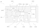
자동온도조절 밸브는 제1 유출구(101), 제2 유입구(102) 및 제2 유출구(104)를 가지며, 밸브 캐비티(10a)와 연통하는 제1 유입구(103)를 또한 갖는다. 본 실시예에서, 상기 유입구들 및 유출구들은 밸브 본체(10)의 외벽에 일체로 형성되며, 이는 외부 부재에 연결될 수 있다. 도 5에서, 밸브 캐비티(10a)를 제2 유출구(104)와 연통시키기 위한 제1 밸브 포트(B) 및 밸브 캐비티(10a)를 제1 유출구(101)와 연통시키기 위한 제2 밸브 포트(A)가 또한 밸브 본체(10)에 구비된다. 제2 밸브 포트(A)는 구체적으로 밸브 캐비티(10a)의 측면 캐비티 벽에 구비되고, 제2 밸브 포트(A)와 제1 유출구(101) 사이에 유출구 통로(10d)가 형성된다. 제1 밸브 포트(B)는 밸브 캐비티(10a)의 단부 캐비티 벽, 즉 도 3의 우측 단부에 있는 캐비티 벽에 형성되고, 좌측 단부는 단부 커버(30)에 의해 차단된 단부 포트이다. 제1 밸브 포트(B)는 제2 유출구 통로를 통해 제2 유출구(104)와 연통하고, 도 3의 제2 유출구 통로는 작은 구멍(10c), 및 제2 유입구(102)와 제2 유출구(104) 사이의 직선 통로(10b)를 포함한다.The thermostatic valve has a
본 명세서의 모든 실시예에 따른 자동온도조절 밸브는 변속기와 냉각기 사이에 사용될 수 있다. 자동온도조절 밸브 내부를 흐르는 매체는 윤활유이다. 즉, 자동온도조절 밸브의 제1 유출구(101)는 냉각기의 유입구와 연통하고, 제2 유입구(102)는 냉각기의 유출구와 연통하며, 제2 유출구(104)는 변속기의 유입구와 연통하고, 제1 유입구(103)는 변속기의 유출구와 연통한다. 변속기에서 유출된 후, 윤활유는 제1 유입구(103)를 통해 자동온도조절 밸브로 들어가고, 이어서 윤활유는 제1 포트(B) 및 제2 유출구(104)를 통해 변속기로 바로 다시 유입되거나, 또는 윤활유는 냉각될 제2 포트(A) 및 제1 유출구(101)를 통해 냉각기로 유입되고, 제2 유입구(102) 및 제2 유출구(104)를 통해 변속기로 복귀한다. 다음의 주요 작동 과정이 또한 본원에 의해 예시된다. 다만, 변속기와 냉각기는 본원에서 자동온도조절 밸브의 전형적인 적용일 뿐이라는 것으로 이해될 수 있다. 변속기 외에도 자동온도조절 밸브는 매체 유로를 조정하기 위해 온도를 제어하는 데 필요한 다른 응용 분야에도 적용될 수 있음이 명백하다.Thermostatic valves according to all embodiments of the present disclosure may be used between the transmission and the cooler. The medium flowing inside the thermostatic valve is lubricant. That is, the
구체적으로, 본 실시예의 밸브 코어(40)는 제1 밸브 포트(B) 및 제2 밸브 포트(A)의 개폐를 전환하도록 이동 가능하다. 도 3에 도시된 바와 같이, 밸브 코어(40)는 우측으로 이동하여 제1 밸브 포트(B)를 차단하고 제2 밸브 포트(A)를 개방할 수 있고, 밸브 코어(40)는 좌측으로 이동하여 제2 밸브 포트(A)를 차단하고 제1 밸브 포트(B)를 개방할 수 있다. 제1 밸브 포트(B) 및 제2 밸브 포트(A)의 개방 및 폐쇄는 2개의 유로의 전환을 실현하고, 자동온도조절 밸브가 변속기와 냉각기에 적용될 때, 윤활유는 냉각기를 통과함으로써 냉각될 수 있거나 냉각 없이 변속기로 바로 복귀될 수 있다.Specifically, the
밸브 코어(40)의 이동은 주로 밸브 캐비티(10a)에 구비된 리턴 스프링(202) 및 메모리 스프링(201)에 의해 이루어진다. 메모리 스프링(201)은 형상기억합금 재료(SMA: Shape Memory Alloy)로 만들어진 스프링이다. 리턴 스프링(202)은 밸브 코어(40)가 제1 밸브 포트(B)를 개방하게 하는 복귀력을 제공할 수 있다. 본 실시예에서, 리턴 스프링(202)은 인장 스프링, 즉 당기는 힘을 제공하는 스프링이다. 도 3에서 밸브 코어(40)의 당기는 힘의 방향은 좌측이다. 좌측 스프링은 밸브 코어(40)를 연결하는 역할을 할 수 있다. 밸브 코어(40)는 무게를 줄이고 이동을 용이하게 하기 위해 도면에 도시된 바와 같이 I자형 축 방향 단면을 갖는 구조로 가공될 수 있다. 온도가 특정 값으로 상승하면, 메모리 스프링(201)의 탄성 특성이 활성화되고, 메모리 스프링(201)은 탄성력을 제공하는 탄성위치에너지를 갖는다. 탄성력의 방향은, 밸브 코어(40)를 복귀력에 대항하여 이동하도록 구동하기 위해, 당기는 힘의 방향과 반대이다. 활성화되는 메모리 스프링(201)의 탄성에 대응하는 특정 값은 필요조건에 따라 재료를 선택함으로써 결정될 수 있고, 따라서 경로 전환이 요구되는 주위 온도에서의 온도 증가로 인해 메모리 스프링(201)이 변형될 수 있다.The movement of the
본 실시예의 다음의 작동 원리는 다음과 같이 설명된다.The following operating principle of this embodiment is explained as follows.
도 3에 도시된 작동 상태에서, 매체(예를 들어, 변속기의 상기 윤활유)는 제1 유입구(103)로부터 자동온도조절 밸브의 밸브 캐비티(10a)로 흐른다. 제2 밸브 포트(A)가 폐쇄되고 제1 밸브 포트(B)가 개방되기 때문에, 매체는 제1 밸브 포트(B)를 통해 작은 구멍(10c), 직선 통로(10b) 및 제2 유출구(104)로 흘러서 변속기로 복귀한다.In the operating state shown in Fig. 3, a medium (for example, the lubricating oil of the transmission) flows from the
매체의 온도가 특정 값으로 상승하면, 자동온도조절 밸브는 도 4에 도시된 작동 상태에 있고, 메모리 스프링(201)의 탄성 특성이 활성화되며, 생성된 탄성력은 리턴 스프링(202)의 복귀력보다 크다. 이때, 밸브 코어(40)는 메모리 스프링(201)과 리턴 스프링(202)에 의해 가해지는 힘 사이의 차이에 의해 제1 밸브 포트(B)를 향해 이동한다. 밸브 코어(40)는 제1 밸브 포트(B)를 차단하고 제2 밸브 포트(A)를 개방할 수 있다. 매체가 제1 유입구(103)로부터 유입된 후, 매체는 냉각될 제2 밸브 포트(A), 유출구 통로(10d) 및 제1 유출구(101)를 통해 냉각기에 유입된다. 냉각된 윤활유는 냉각기 밖으로 유출된 다음, 제2 유입구(102)로부터 밸브 캐비티(10a)로 유입되고, 직선 통로(10b)와 제2 유출구(104)를 통해 변속기에 다시 유입된다.When the temperature of the medium rises to a certain value, the thermostatic valve is in the operating state shown in FIG. 4, the elastic properties of the
매체의 온도가 특정 값 아래로 떨어진 후에는, 메모리 스프링(201)의 탄성 특성이 작동하지 않고, 탄성력이 감소된 다음 사라지며, 밸브 코어(40)는 리턴 스프링(202)의 복귀력에 의해 제1 밸브 포트(B)로부터 멀어진다. 이때, 제1 밸브 포트(B)가 개방되고, 제2 밸브 포트(A)는 폐쇄되며, 밸브 코어(40)는 도 3에 도시된 상태로 복귀한다. 본 실시예에 따른 메모리 스프링(201)은 밸브 코어(40)의 동작을 구동하는 열 액추에이터로서 기능하며, 구조가 간단하다는 것을 알 수 있다.After the temperature of the medium falls below a certain value, the elastic properties of the
본 실시예에서, 메모리 스프링(201) 및 리턴 스프링(202)은 모두 단부 커버(30)와 밸브 코어(40) 사이에 구비된다. 배열 방식이 이것으로 한정되지 않음은 명백하다.In this embodiment, the
도 6 내지 도 7을 참조하면, 도 6은 본원의 제2 실시예에 따른 자동온도조절 밸브의 구조를 도시한 단면도로서, 제2 밸브 포트가 폐쇄되고 제1 밸브 포트가 개방된 상태를 나타내며, 도 7은 밸브 코어가 우측으로 이동된 후의 도 6의 자동온도조절 밸브의 개략도로서, 제1 밸브 포트가 폐쇄되고 제2 밸브 포트가 개방된 상태를 나타낸다.6 to 7, FIG. 6 is a cross-sectional view showing the structure of a thermostatic valve according to a second embodiment of the present application, showing a state in which the second valve port is closed and the first valve port is opened, FIG. 7 is a schematic view of the thermostatic valve of FIG. 6 after the valve core is moved to the right, showing a state in which the first valve port is closed and the second valve port is opened.
본 실시예는 기본적으로 제1 실시예와 동일하다. 메모리 스프링(201)은 단부 커버(30)와 밸브 코어(40) 사이에 위치된다. 메모리 스프링(201)은 일 단부가 밸브 코어(40)의 다른 일 단부와 접촉하고, 다른 일 단부는 단부 커버(30)와 접촉한다. 밸브 본체(10)에 단차진 구멍이 형성되고, 단차진 구멍 중 큰 구멍은 밸브 캐비티(10a)이고, 제1 밸브 포트(B)는 작은 구멍(10c)과 큰 구멍의 연결부에 형성된다. 차이점은, 본 실시예에서는, 도 6의 리턴 스프링(202)이 당기는 힘 대신에 탄성복원력을 제공한다는 점, 즉 리턴 스프링(202) 및 메모리 스프링(201)이 각각 밸브 코어(40)의 양단부에 구비될 수 있다는 점이다. 리턴 스프링(202)의 일 단부는 밸브 코어(40)의 일 단부와 접촉하고, 리턴 스프링(202)의 타 단부는 밸브 본체(10)에 맞닿아 밸브 코어(40)에 반대 방향 힘을 제공한다.This embodiment is basically the same as the first embodiment. The
구체적으로, 리턴 스프링(202)은 작은 구멍(10c)에 구비되고, 작은 구멍(10c)에는 단차부가 구비된다. 리턴 스프링(202)은 밸브 코어(40)와 단차부 사이에서 미리 압축되어 밸브 코어(40)를 제1 밸브 포트(B)로부터 멀어지게 하기 위한 탄성복원력을 제공하며, 탄성복원력의 방향은 밸브 코어(40)에 인가된 메모리 스프링(201)의 탄성력의 방향과 반대이다. 이때, 리턴 스프링(202)과 대향하는 밸브 코어(40)의 우측 단부에는 리턴 스프링(202) 내로 삽입되는 돌출부가 구비되어, 리턴 스프링(202)을 조립하고 또한 밸브 코어(40)의 위치 결정 및 안내 역할을 할 수 있다.Specifically, the
물론, 작은 구멍(10c)에 단차부가 제공되지 않을 수 있고, 리턴 스프링(202)의 우측 단부는 직선 통로(10b)의 내벽에 직접 맞닿을 수 있다. 또는 직선 통로(10b)의 내벽에 오목 구멍이 제공되고, 리턴 스프링(202)의 우측 단부는 오목 구멍에 직접 맞닿는다. 리턴 스프링(202)은 밸브 코어(40)와 밸브 캐비티(10a)의 우측 단부의 캐비티 벽 사이에서 미리 압축될 수 있다.Of course, a step may not be provided in the
또한, 제1 및 제2 실시예에서, 밸브 코어(40)의 우측 단부는 밸브 코어(40)가 우측으로 이동할 때 제1 밸브 포트(B)를 차단할 수 있는 실링부이고, 메모리 스프링(201)은 제2 밸브 포트(A)의 실링부로서 기능한다. 매체의 온도가 낮을 때, 메모리 스프링(201)은 압축되어 빡빡한 상태이고 제2 밸브 포트(A)의 위치에 대응하여, 제2 밸브 포트(A)를 차단할 수 있다. 메모리 스프링(201)이 가열 및 팽창될 때는, 메모리 스프링(201)이 변형 및 신장되고, 메모리 스프링(201)의 직경이 감소하며, 제2 밸브 포트(A)와 메모리 스프링(201) 사이에 간극이 나타나고, 메모리 캐비티(201)의 여러 스프링 코일들 사이에 노치가 나타날 수도 있으며, 밸브 캐비티(10a) 내의 매체는 간극 및 노치를 통해 제2 밸브 포트(A)로 흐른 다음 유출될 수 있다. 이때, 제2 밸브 포트 A가 개방된다. 이 구성에 의해, 메모리 스프링(201)은 밸브 코어(40)의 이동을 구동하는 열 액추에이터로서 기능할뿐만 아니라 실링부로서도 작용하여, 밸브 코어(40)의 구조를 단순화함을 알 수 있다.Further, in the first and second embodiments, the right end of the
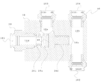
물론, 제2 밸브 포트(A)를 차단하는 방식은 이에 한정되지 않는다. 도 8 내지 도 11을 참조하면, 도 8은 본원의 제3 실시예에 따른 초기 상태에서의 자동온도조절 밸브의 구조를 도시한 단면도로서, 제1 밸브 포트(B)가 미리 설정된 개방도를 갖고 제2 밸브 포트(A)가 미리 설정된 개방도를 갖는 상태를 나타내며, 도 9는 온도가 특정 값으로 상승하고 메모리 스프링(201)이 변형된 후의 도 8의 자동온도조절 밸브의 개략도로서, 제1 밸브 포트(B)가 폐쇄되고 제2 밸브 포트(A)가 개방된 상태를 나타내고, 도 10은 온도가 특정 값 아래로 떨어지고 메모리 스프링(201)이 특성을 상실한 후의 도 9의 자동온도조절 밸브의 개략도로서, 제1 밸브 포트(B)가 개방되고 제2 밸브 포트(A)가 폐쇄된 상태를 나타내며, 도 11은 도 8의 밸브 코어(40)의 구조를 도시한 개략도이다.Of course, the method of blocking the second valve port A is not limited thereto. 8 to 11, FIG. 8 is a cross-sectional view showing the structure of a thermostatic valve in an initial state according to a third embodiment of the present application, wherein the first valve port B has a preset opening degree The second valve port (A) shows a state having a preset opening degree, and FIG. 9 is a schematic diagram of the thermostatic valve of FIG. 8 after the temperature rises to a specific value and the
본 실시예에서, 제2 밸브 포트(A)가 밸브 캐비티(10a)의 측면 캐비티 벽에도 구비되고, 제1 밸브 포트(B)는 밸브 캐비티(10a)의 단부 캐비티 벽에 구비된다. 이에 비해, 본 실시예의 밸브 코어(40)에는 슬리브 부분(402)이 추가로 구비되고, 메모리 스프링(201)은 슬리브 부분(402)에 구비되며 단부 커버(30)와 밸브 코어(40) 사이에 위치된다. 이때, 밸브 코어(40)의 우측 단부는 제1 밸브 포트(B)를 차단하기 위한 제1 실링부를 형성하고, 밸브 코어(40)상의 슬리브 부분(402)은 제2 밸브 포트(A)를 차단하기 위한 제2 실링부를 형성한다. 구체적으로, 슬리브 부분(402)의 외벽은 밸브 캐비티(10a)의 측면 캐비티 벽을 따라 슬라이드되어 제2 밸브 포트(A)를 차단하거나 개방할 수 있다. 이때, 메모리 스프링(201)은 밸브 코어(40)를 온도 변화에 따라 이동하도록 구동하는 열 액추에이터로서만 기능한다.In the present embodiment, the second valve port A is also provided on the side cavity wall of the valve cavity 10a, and the first valve port B is provided on the end cavity wall of the valve cavity 10a. In contrast, the
메모리 스프링(201)의 조립을 용이하게 하기 위해, 밸브 코어(40)와 대향하는 단부 커버(30)의 내측 단부면 상에 돌출 플랫폼이 제공되고, 메모리 스프링(201)의 일 단부는 돌출 플랫폼 상에 슬리브된다. 밸브 코어(40)는 축 방향으로 연장되는 본체부(401) 및 본체부(401)의 일부의 외부에 슬리브된 슬리브 부분(402)을 포함한다. 본체부(401)의 좌측 단부는 슬리브 부분(402) 내로 연장된다. 메모리 스프링(201)의 다른 일 단부는 본체부(401)의 좌측 단부에 슬리브된다. 밸브 코어(40)의 슬리브 부분(402) 및 본체부(401)는 도 11에 도시된 바와 같이 개별적으로 가공되거나 일체로 형성될 수 있다.To facilitate assembly of the
제3 실시예에서는, 제1 및 제2 실시예와 동일하게, 밸브 본체(10)에 단차진 구멍이 역시 형성된다. 단차진 구멍 중 큰 구멍은 밸브 캐비티(10a)이고, 제1 밸브 포트(B)는 단차진 구멍의 큰 구멍과 작은 구멍(10c)의 연결부에 형성된다. 또한, 밸브 코어(40)의 본체부(401)의 우측 단부는 제1 실링부로서 기능하며 안내 로드(403)에도 연결된다. 안내 로드(403) 및 본체부(401)는 개별적으로 형성되거나 일체로 형성될 수 있다. 안내 로드(403)는 작은 구멍(10c)에 삽입되어 밸브 코어(40)의 이동을 안내할 수 있다. 안내 로드(403)가 안내를 위해 작은 구멍(10c)에 삽입되도록 밸브 코어(40) 상에 제공된다는 특징은 다른 실시예에도 적용가능하다. 도 11에 도시된 바와 같이, 제1 밸브 포트(B)와 대향하는 밸브 코어(40)의 단부는 중량을 줄이고 재료를 절약하기 위해 중공일 수 있다.In the third embodiment, similarly to the first and second embodiments, a stepped hole is also formed in the
제2 실시예에서, 제1 밸브 포트(B)를 실링하기 위한 실링부로서, 밸브 코어(40)의 우측 단부에는 리턴 스프링(202) 내로 삽입되는 돌출 플랫폼이 제공된다. 리턴 스프링(202)은 작은 구멍(10c)에 위치되며 또한 특정 안내 역할을 할 수 있다. 그러나, 제3 실시예에서, 안내 로드(403)는 안내를 위해 작은 구멍(10c)에 직접 삽입되며, 안내 효과가 더 우수하다. 슬리브 부분(402)이 구비되기 때문에, 리턴 스프링(202)을 설치하기 위해 작은 구멍(10c)의 구멍 벽 상에 단차부를 가공할 필요가 없다. 도 8에 도시된 바와 같이, 리턴 스프링(202)은 슬리브 부분(402)과 밸브 캐비티(10a)의 단부 캐비티 벽 사이에 배열될 수 있다.In the second embodiment, as a sealing portion for sealing the first valve port B, a protruding platform inserted into the
또한, 제3 실시예에서, 밸브 코어(40)에는 슬리브 부분(402)이 구비되기 때문에, 슬리브 부분(402)은 밸브 캐비티(10a)의 측면 캐비티 벽과 슬라이딩 결합되고, 도 11에 도시된 바와 같이 제1 유입구(103)에 가까운 슬리브 부분(402)의 바닥(즉, 도 8에서 바닥 아래쪽)에 개구(402b)가 구비되므로, 매체는 슬리브 부분(402)의 내부 캐비티 내로 흐를 수 있고 따라서 제2 밸브 포트(A)로 흐른다.Further, in the third embodiment, since the
매체가 메모리 스프링(201)과 더 빠르고 더 많이 접촉하는 것을 용이하게 하기 위해, 바닥을 관통하는 안내 유입구(402a)가 도 8에서 제1 유입구(103)로부터 멀리 떨어진 슬리브 부분(402)의 바닥(도 8에서 바닥 위쪽)에 추가로 구비되며, 유동 안내 통로로서, 안내 유입구(402a)는 밸브 캐비티(10a)를 슬리브 부분(402)의 내부 캐비티와 연통 시키도록 구성된다. 안내 유입구(402a)의 개수는 하나 이상일 수 있다.In order to facilitate faster and more contact of the media with the
제3 실시예에서, 밸브 코어(40)의 본체부(401)의 좌측 단부에 단부 돌출 플랫폼(401a)이 제공되는 점에 유의해야 한다. 초기 상태에서, 즉 공장을 떠날 때, 메모리 스프링(201)의 일 단부는 단부 돌출 플랫폼(401a) 주위에 둘러싸이고, 단부 돌출 플랫폼(401a)과 본체부(401)에 의해 형성된 단차면에 맞닿는데, 이 단차면은 메모리 스프링(201)의 단부의 초기 위치이다. 도 8에 도시된 바와 같이, 제1 밸브 포트(B)는 완전히 개방되지 않고 미리 설정된 개방도를 가지며, 제2 밸브 포트(A)는 또한 미리 설정된 초기 개방도를 가지므로, 자동온도조절 밸브는 제2 밸브 포트(A)가 초기 상태에서 항상 개방되는 특성을 가지며, 이로써 변속기에 윤활유를 채우는 동시에 초기 상태의 냉각기에 윤활유를 채우는 것을 용이하게 하여 초기 충전의 요건을 충족시킨다. 즉, 두 밸브 포트가 모두 개방된다.It should be noted that in the third embodiment, an
그 후, 윤활유의 온도가 특정 값으로 상승할 때, 메모리 스프링(201)은 어느 정도 변형되고 팽창함으로써, 단부 돌출 플랫폼(401a)으로부터 분리되고 더 큰 외경으로 본체부(401)를 둘러싼다. 메모리 스프링(201)은 이후 정상 작동 상태로 전환되고, 도 9에 도시된 바와 같이 항상 본체부(401)를 둘러싸며, 변형되어 슬리브 부분(402)의 바닥 위치에 맞닿는다. 이 위치가 작동 위치이다. 이때, 제1 밸브 포트(B)는 메모리 스프링(201)의 탄성력에 의해 폐쇄 상태로 유지된다. 본원에서 설명된 메모리 스프링(201)의 단부의 초기 위치 및 작동 위치는 단부와 밸브 본체(10)(밸브 캐비티의 캐비티 벽 또는 밸브 본체(10)의 단부 커버(30))의 상대 위치 또는 단부와 밸브 코어(40)의 상대 위치를 지칭하며, 밸브 코어(40)가 이동함에 따라 변하지 않는다.Then, when the temperature of the lubricating oil rises to a certain value, the
온도가 특정 값보다 낮으면, 메모리 스프링(201)은 그 특성을 상실한다. 리턴 스프링(202)의 복귀력의 작용에 의해, 밸브 코어(40)가 이동하여 메모리 스프링(201)을 압축시킨다. 슬리브 부분(402)의 하부와 단부 커버(30) 사이의 거리는 본체부(401)의 돌출 플랫폼과 단부 커버(30) 사이의 거리보다 크며, 따라서 메모리 스프링(201)이 본체부(401)의 돌출 플랫폼으로부터 분리되어 본체부(401)를 둘러싸는 경우, 밸브 코어(40)는 리턴 스프링(202)의 작용에 의해 단부 커버(30)에 더 가깝고, 도 10에 도시된 바와 같이, 슬리브 부분(402)은 제2 밸브 포트(A)를 차단하여 미리 설정된 초기 개방도를 제거할 것이다.If the temperature is lower than a certain value, the
본 실시예에 따라 설정 방법이 제공됨을, 즉 2단계 단차부(단부 돌출 플랫폼(401a)과 본체부(401) 사이의 단차면이 제1 단차면이고, 슬리브 부분(402)의 바닥이 제2 단차면임)가 밸브 코어(40) 상에 제공되고, 초기 위치 및 작동 위치는 각각 제1 단차면 및 제2 단차면에 의해 형성됨을 알 수 있다. 메모리 스프링(201)이 초기 위치에 있을 때, 제1 밸브 포트(B)는 미리 설정된 개방도를 가지며, 메모리 스프링(201)이 초기 위치에 있을 때 밸브 코어(40)와 제1 밸브 포트(B) 사이의 거리는 메모리 스프링(201)이 작동 위치에 있고 온도가 특정 값보다 낮을 때 밸브 코어(40)와 제1 밸브 포트(B) 사이의 거리보다 작다.According to this embodiment, a setting method is provided, that is, a two-step stepped portion (the stepped surface between the stepped projecting
밸브 코어(40)가 특정 위치에 있을 때, 초기 위치와 단부 커버(40) 사이의 거리는 작동 위치와 단부 커버(40) 사이의 거리보다 작다. 이러한 방식으로, 메모리 스프링(201)이 (특정 값의 영향을 받지 않는) 임의의 온도 환경에 있을 때, 제1 밸브 포트(B)는 폐쇄 상태를 유지하고, 제2 밸브 포트(A)는 미리 설정된 개방도를 갖는다(제2 밸브 포트(A)가 구비되지 않으면, 매체는 제1 유출구(104)로 직접 흐를 수 있다). 작동 위치에서 이후에는, 단부 커버(30)와 밸브 코어(40) 사이의 거리가 더 길어지므로, 리턴 스프링(202)은 밸브 코어(40)가 메모리 스프링(202)을 더 많은 거리만큼 압축하도록 구동함으로써, 제1 밸브 포트(B)를 개방하고 제2 밸브 포트(A)를 폐쇄할 수 있다.When the
초기 위치와 작동 위치의 설정은 밸브 코어(40)와 단부 커버(30) 또는 밸브 코어(40)와 밸브 본체(10) 사이의 거리를 조정하여, 메모리 스프링(201)의 양단부 사이의 거리가 2개의 작동 위치에서 상이한 정도로 압축될 수 있고, 이에 의해 제1 밸브 포트(B)의 개폐를 달성하는 것임을 알 수 있다. 따라서, 초기 위치 및 작동 위치는 밸브 코어(40) 또는 밸브 본체(10)에서 설정될 수도 있고, 이는 2단계 단차부 방법에 의해서도 달성될 수 있으며, 밸브 코어(40)와 밸브 본체(10) 양쪽 모두가 초기 위치 및 작동 위치로, 또는 밸브 코어(40)와 단부 커버(30) 양쪽 모두가 초기 위치 및 작동 위치로 설정될 수 있으므로, 메모리 스프링(201)의 양단부가 초기 위치 또는 작동 위치에 맞닿을 수 있다.Setting the initial position and the operating position adjusts the distance between the
상기 실시예에서, 제1 유출구(101), 제2 유입구(102), 제2 유출구(104) 및 제1 유입구(103)는 모두 밸브 본체(10)의 측벽에 구비되고, 제1 밸브 포트(B)는 밸브 캐비티(10a)의 단부 캐비티 벽에 구비되며, 제2 밸브 포트(A)는 밸브 캐비티(10a)의 측면 캐비티 벽에 구비된다. 제2 유출구(104)와 제2 유입구(102)는 서로 반대쪽이며, 제2 유출구(104)와 제2 유입구(102) 사이에 직선 통로(10b)가 형성된다(이하에 설명된 다른 실시예에서도 직선 통로(10b)가 형성됨). 제1 밸브 포트(B)는 직선 통로(10b)와 연통하며, 구체적으로 상기 실시예에서 단차진 구멍 중 작은 구멍(10c)을 통해 직선 통로(10b)와 연통된다. 이러한 방식으로, 제1 유입구(103) 및 제2 유입구(102)는 제2 유출구(104)로의 통로를 공유할 수 있어, 구조를 단순화하고 가공을 용이하게 한다. 물론, 다른 설정 방법도 채택될 수 있다.In the above embodiment, the
자동온도조절 밸브의 유입구, 유출구 및 밸브 포트는 다른 방식으로 설정될 수도 있다.The inlet, outlet, and valve ports of the thermostatic valve may be set in different ways.
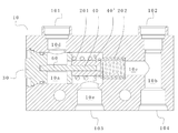
도 12 내지 도 15를 참조하면, 도 12는 본원의 제4 실시예에 따른 초기 상태에서의 자동온도조절 밸브의 구조를 도시한 단면도로서, 제1 밸브 포트(B)가 미리 설정된 개방도를 갖고 제2 밸브 포트(A)가 미리 설정된 개방도를 갖는 상태를 나타내며, 도 13은 온도가 특정 값으로 상승하고 메모리 스프링(201)이 변형된 후의 도 12의 자동온도조절 밸브의 개략도로서, 제1 밸브 포트가 폐쇄되고 제2 밸브 포트가 개방된 상태를 나타내고, 도 14는 온도가 특정 값 아래로 떨어지고 메모리 스프링(201)이 특성을 상실한 후의 도 13의 자동온도조절 밸브의 개략도로서, 제1 밸브 포트가 개방되고 제2 밸브 포트가 폐쇄된 상태를 나타내며, 도 15는 도 12의 단부 커버(30)의 구조를 도시한 개략도이다.12 to 15, FIG. 12 is a cross-sectional view showing the structure of a thermostatic valve in an initial state according to a fourth embodiment of the present application, wherein the first valve port B has a preset opening degree The second valve port (A) shows a state having a preset opening degree, and FIG. 13 is a schematic diagram of the thermostatic valve of FIG. 12 after the temperature rises to a specific value and the
본 실시예에서, 단부 커버(30)는 실제로 밸브 본체(10)의 단부 포트 위치를 덮을 뿐만 아니라 외부와 통신하기 위한, 특히 본 실시예에서는 냉각기와 통신하기 위한 커넥터로서 기능하는 시트 전환 구조도 된다. 전환 시트에는 전환 시트의 내외부를 관통하는 통로가 구비되며, 통로에 의해 유출구 통로(10d)가 형성된다. 유출구 통로(10d)의 내부 단부 포트는 제2 밸브 포트(A)이고, 외부 단부 포트는 제1 유출구(101)이다. 이때, 제2 밸브 포트(A) 및 제1 밸브 포트(B)는 밸브 캐비티(10a)의 축 방향을 따라서 분포된다. 이러한 방식으로, 밸브 코어(40)의 이동 중에, 밸브 코어(40)의 일 단부는 제1 밸브 포트(B)를 차단하기 위한 제1 실링부일 수 있고, 타 단부는 제2 밸브 포트(A)를 차단하기 위한 제2 실링부일 수 있다.In this embodiment, the
이러한 방식으로, 밸브 코어(40)가 제1 밸브 포트(B) 및 제2 밸브 포트(A)를 차단하는 작업이 더욱 편리하고, 밸브 코어(40)는 가공이 더 쉽다. 이 실시예에서, 시트 전환 구조를 갖는 단부 커버(30)에 의해 형성된 자동온도조절 밸브의 제1 유출구(101)에 추가하여, 제2 유출구(104), 제2 유입구(102) 및 제1 유입구(103) 또한 밸브 본체(10)에 외부로부터 연결된 커넥터(50)에 의해 형성된다. 제1 내지 제3 실시예에서, 외부와 연통하는 유출구 및 유입구는 각각 밸브 본체(10) 상에 커넥터 형 구조로서 직접 형성되며, 두 해결책 모두 본 발명의 모든 실시예에 적용 가능하다.In this way, it is more convenient for the
또한, 제4 실시예에서, 미리 설정된 초기 개방도의 설정도 수행된다. 도 15를 참조하여 이해될 수 있는 바와 같이, 전환 시트의 밸브 코어(40)를 향한 내측 단부에 2단계 단차부가 구비되고, 제1 단차부의 외경은 제2 단차부의 외경보다 작아서, 양쪽 다 밸브 코어(40)와 대향하는 제1 단차면(301) 및 제2 단차면(302)을 형성하며, 제1 단차면(301)은 초기 위치이고 제2 단차면(302)은 작동 위치이다. 밸브 코어(40)와 초기 위치 사이의 거리는 밸브 코어(40)와 작동 위치 사이의 거리보다 작다. 이러한 방식으로, 공장 출고 초기 상태에서, 메모리 스프링(201)의 좌측 단부는 밸브 코어(40)의 제1 단차부 주위에 둘러싸이고 제1 단차면(301)에 맞닿는다. 이때, 도 12에 도시된 바와 같이, 제1 밸브 포트(B)는 폐쇄되고 제2 밸브 포트(A)는 미리 설정된 초기 개방도를 가지므로, 자동온도조절 밸브는 제2 밸브 포트(A)가 초기 상태에서 항상 개방되는 특성을 가짐으로써 초기 상태에서 윤활유를 변속기에 채우는 동시에 윤활유를 냉각기에 채우는 것을 용이하게 하여 초기 충전의 요건을 충족시킨다. 물론, 제2 밸브 포트(A)가 구비되지 않으면, 메모리 스프링(201)은 초기 위치에 맞닿고, 제1 밸브 포트(B)는 폐쇄되며, 윤활유는 제1 유출구(101)를 통해 냉각기로 직접 유입될 수 있다.Further, in the fourth embodiment, the setting of a preset initial opening degree is also performed. As can be understood with reference to FIG. 15, a two-stage stepped portion is provided at the inner end toward the
그 후, 윤활유의 온도가 특정 값으로 상승하면, 메모리 스프링(201)은 어느 정도 변형되어 팽창함으로써, 제1 단차부로부터 분리되어 제2 단차부 주위를 둘러싼다. 그 후, 메모리 스프링(201)은 정상 작동 위치로 전환되고 도 13에 도시된 바와 같이 항상 제2 단차부 주위로 둘러싸일 것이다. 메모리 스프링(201)은 또한 제2 단차면(302)에 맞닿도록 변형된다. 이때, 제1 밸브 포트(B)는 메모리 스프링(201)의 탄성력에 의해 폐쇄된 상태로 유지된다.Then, when the temperature of the lubricating oil rises to a specific value, the
온도가 특정 값보다 낮으면, 메모리 스프링(201)은 그 특성을 상실한다. 리턴 스프링(202)의 복귀력의 작용에 의해, 밸브 코어(40)가 이동하여 메모리 스프링(201)을 압축시킨다. 제2 단차면(302)과 밸브 코어(40) 사이의 거리는 제1 단차면(301)과 밸브 코어(40) 사이의 거리보다 크고, 따라서 메모리 스프링(201)이 제1 단차부로터 분리되고 제2 단차부 주위에 둘러싸일 때, 밸브 코어(40)는 리턴 스프링(202)의 작용에 의해 단부 커버(30)에 더 가까울 것이며, 밸브 코어(40)의 좌측 단부는 제2 밸브 포트(A)를 차단하여 미리 설정된 초기 개방도를 제거하고, 제1 밸브 포트(B)는 이제 개방된다.If the temperature is lower than a certain value, the
제4 실시예에서, 밸브 코어(40)의 제2 밸브 포트(A)와 대향하는 단부(도 12에서 좌측 단부, 즉 제2 실링부)의 외주부는 테이퍼진다. 즉, 제2 밸브 포트(A)를 더 잘 차단하고 안내 효과를 갖기 위해, 제2 밸브 포트(A)와 협동하는 테이퍼 형 표면을 갖는다. 메모리 스프링(201)에 용이하게 맞닿을 수 있도록 하기 위해, 밸브 코어(40)의 좌측 단부에는 또한 도 12에 도시된 바와 같이 주변 돌출부가 구비되고, 메모리 스프링(201)의 우측 단부는 주변 돌출부에 맞닿는다. 밸브 코어(40)의 제1 밸브 포트(B)와 대향하는 단부(도 12에서 우측 단부, 즉 제1 실링부)는 돌출 플랫폼을 가지며 돌출 플랫폼은 리턴 스프링(202) 내로 삽입될 수 있다. 리턴 스프링(202)은 작은 구멍(10c)에 배치된다.In the fourth embodiment, the outer circumferential portion of the end (left end in FIG. 12, that is, the second sealing portion) facing the second valve port A of the
밸브 코어(40)는 또한 도 16 내지 도 17에 도시된 바와 같은 다른 구조를 가질 수 있다. 도 16은 본원의 제5 실시예에 따른 초기 상태에서의 자동온도조절 밸브의 구조를 도시한 단면도로서, 제1 밸브 포트(B)가 미리 설정된 개방도를 갖고 제2 밸브 포트(A)가 미리 설정된 개방도를 갖는 상태를 나타내며, 도 17은 온도가 특정 값으로 상승하고 메모리 스프링(201)이 변형된 후의 도 16의 자동온도조절 밸브의 개략도로서, 제1 밸브 포트(B)가 폐쇄되고 제2 밸브 포트(A)가 개방된 상태를 나타낸다.The
본 실시예는 기본적으로 제4 실시예와 동일하며, 차이점은 밸브 코어(40)의 구조에만 있다. 본 실시예에서, 밸브 코어(40)는 구형체이다. 구형 밸브 코어(40)가 제1 밸브 포트(B) 및 제2 밸브 포트(A)를 차단하기 위해 사용될 때, 더 나은 차단 효과가 실현될 수 있다. 다른 실시예에서는, 구형 밸브 코어(40)가 사용될 수도 있거나, 또는 적어도 차단을 위한 부분은 구형 표면으로 가공된다.This embodiment is basically the same as the fourth embodiment, and the difference is only in the structure of the
제5 실시예에서, 시트 전환 구조를 갖는 단부 커버(30) 상에 2단계 단차부가 또한 구비되어, 메모리 스프링(201)은 초기 형상을 갖고 미리 설정된 초기 개방도를 형성하며, 이는 냉각기에 냉각 오일을 채우는 것을 용이하게 한다.In the fifth embodiment, a two-step stepped portion is also provided on the
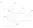
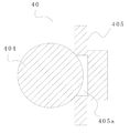
밸브 코어(40)의 구조와 관련하여, 본원의 제6 실시예에 따른 자동온도조절 밸브의 구조를 도시한 단면도로서, 제1 밸브 포트(B)가 폐쇄되고 제2 밸브 포트(A)가 개방된 상태를 나타내는 도 19를 더욱 참조할 수 있고, 도 20은 도 19의 밸브 코어(40)의 구조를 도시한 개략도이다.Regarding the structure of the
밸브 코어(40)의 구조가 서로 연결된 구형부(404)와 실링판(405)을 포함한다는 점을 제외하고, 이 실시예는 제4 및 제5 실시예와 동일하다. 구형부(404)는 제2 밸브 포트(A)를 차단하는데 사용되고, 실링판(405)은 제1 밸브 포트(B)를 차단하는데 사용된다.This embodiment is the same as the fourth and fifth embodiments, except that the structure of the
실링부(405)의 구형부(404)와 대향하는 면에는 오목 구멍(405a)이 구비되어, 구형부(404)는 오목 구멍(405a)에 부분적으로 삽입되어 고정될 수 있고, 이에 의해 구형부(404)와 실링판(405)의 고정을 용이하게 한다. 실링판(405)의 다른 측면에 돌출부가 구비되어 리턴 스프링(202) 내로 삽입되는데, 이는 리턴 스프링(202)의 위치설정, 안내 및 용이한 설치의 역할을 한다. 이때, 구형부(404)는 2개의 밸브 포트의 차단을 동시에 충족시킬 필요가 없으며, 메모리 스프링(201)은 단부 커버(30)와 실링판(405) 사이에 위치된다.A concave hole 405a is provided on a surface of the sealing
도 21을 다시 참조하면, 도 21은 본원의 제7 실시예에 따른 자동온도조절 밸브의 구조를 도시한 단면도로서, 제1 밸브 포트(B)가 폐쇄되고 제2 밸브 포트(A)가 개방된 상태를 나타낸다.Referring back to FIG. 21, FIG. 21 is a cross-sectional view showing the structure of the thermostatic valve according to the seventh embodiment of the present application, wherein the first valve port B is closed and the second valve port A is opened. State.
제4 내지 제6 실시예와 비교하여, 본 실시예의 차이점은 밸브 요소(40)의 구조에만 있다. 이 실시예에서 밸브 코어(40)는 원통형이며, 밸브 코어(40)의 2개의 단부면은 각각 제1 밸브 포트(B) 및 제2 밸브 포트(A)를 실링하는 데 사용된다. 제1 밸브 포트(B)와 대향하는 밸브 코어(40)의 측면에는 돌기가 또한 구비되어 리턴 스프링(202) 내로 삽입되는데, 이는 리턴 스프링(202)의 위치설정, 안내 및 용이한 설치의 기능을 갖는다.Compared to the fourth to sixth embodiments, the difference of this embodiment is only in the structure of the
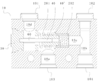
도 22 내지 도 25를 연속적으로 참조하면, 도 22는 본원의 제8 실시예에 따른 자동온도조절 밸브의 구조를 도시한 단면도로서, 제1 밸브 포트(B)가 개방되고 제2 밸브 포트(A)가 폐쇄된 상태를 나타내며, 도 23은 온도가 상승하고 메모리 스프링이 변형된 후의 도 22의 자동온도조절 밸브의 개략도로서, 제1 밸브 포트(B)가 폐쇄되고 제2 밸브 포트(A)가 개방된 상태를 나타내고, 도 24는 설치 후 도 22의 단부 커버, 밸브 코어, 리턴 스프링 및 메모리 스프링을 도시한 개략도이며, 도 25는 도 24의 개략사시도이다.22 to 25, FIG. 22 is a cross-sectional view showing the structure of the thermostatic valve according to the eighth embodiment of the present application, wherein the first valve port B is opened and the second valve port A ) Is a closed state, and FIG. 23 is a schematic view of the thermostatic valve of FIG. 22 after the temperature rises and the memory spring is deformed, the first valve port B is closed and the second valve port A is FIG. 24 is a schematic view showing the end cover, valve core, return spring and memory spring of FIG. 22 after installation, and FIG. 25 is a schematic perspective view of FIG. 24.
제4 실시예 내지 제7 실시예와 비교하여, 본 실시예의 제2 밸브 포트(A)는 단부 커버(30)에도 구비되지만(단부 커버는 시트 전환 구조로 구현되지 않음), 제1 유출구(101)는 여전히 밸브 본체(10)의 내벽에 제공된다. 이때, 단부 커버(30)와 밸브 본체(10)에는 제1 유출구(101)를 제2 밸브 포트(A)와 연통시키는 유출구 통로(10d)가 구비되며, 유출구 통로(10d)는 실제로는 도 22에 도시된 바와 같이 "L"자형에 상당하다. 제2 밸브 포트(A)의 위치는 제4 내지 제7 실시예의 위치와 유사하며, 이는 밸브 코어(40)가 더욱 편리하게 이동하여 차단을 실현할 수 있게 한다.Compared to the fourth to seventh embodiments, the second valve port A of this embodiment is also provided in the end cover 30 (the end cover is not implemented with a seat switching structure), but the first outlet 101 ) Is still provided on the inner wall of the
또한, 본 실시예에서, 단부 커버(30)에는 구멍이 구비되고, 자동온도조절 밸브에는 밸브 스템(60)이 추가로 구비된다. 밸브 스템(60)의 일 단부는 축 방향을 따라 구멍에 삽입되어 고정될 수 있고, 밸브 스템(60)의 타 단부는 단부 커버(30)로부터 연장된다. 단부 커버(30)로부터 연장되는 밸브 스템(60)의 타 단부는 밸브 코어(40) 내로 삽입될 수 있고 밸브 코어(40)와 슬라이딩 결합된다. 이러한 방식으로, 밸브 코어(40)는 이동 과정 중에 밸브 스템(60)을 따라 이동할 수 있고, 이에 의해 양호한 위치설정 및 안내 효과를 가질 수 있다.Further, in this embodiment, the
도 24 및 도 25에 도시된 바와 같이, 단부 커버(30)의 외주에 환형 통로가 형성되는데, 이는 매체가 제1 유출구(101)로 유동하는 것을 용이하게 한다. 도 24에서, 단부 커버(30)의 좌측 단부는 밸브 캐비티(10a)의 좌측 단부 포트를 차단하는데 사용되며, 제2 밸브 포트(A)는 우측 단부에 형성되고, 좌측 단부와 우측 단부 사이에 커넥터가 구비된다. 밸브 스템(60)은 제2 밸브 포트(A)로부터 커넥터로 삽입되어 좌측 단부로 들어간다. 단부 커버(30)의 좌측 단부, 우측 단부 및 커넥터는 일체로 형성되어, 구조가 신뢰할 수 있고, 밸브 스템(60) 및 메모리 스프링(201)의 안정적인 설치를 달성하며, 이들 부재가 먼저 조립된 후에 밸브 커버(10a) 내로 설치될 수 있다. 물론, 단부 커버(30)의 좌측 단부, 우측 단부 및 커넥터는 개별적으로 형성된 후 연결될 수도 있다.24 and 25, an annular passage is formed on the outer circumference of the
명백하게, 밸브 스템(60)은 다른 실시예에도 적용 가능하다. 도 19에 도시된 바와 같이, 시트 전환 구조를 갖는 단부 커버(30)에 제1 유출구(101)가 구비되는 실시예의 경우, 밸브 스템은 단부 커버(30)의 통로 내로 삽입될 수 있고, 밸브 스템의 단부는 커넥터에 의해 통로의 측벽에 고정될 수 있다.Obviously, the
제8 실시예에서, 밸브 스템(60)이 단부 커버(30)에 고정되는 점에 유의해야 한다. 밸브 스템(60)은 밸브 코어(40)에 고정되고 단부 커버(30)에 슬라이딩 결합될 수도 있음을 이해할 수 있다. 비교하면, 밸브 스템(60)이 단부 커버(30)에 고정되는 경우, 밸브 코어(40)는 보다 매끄럽고 신뢰성 있게 작동할 수 있다.It should be noted that in the eighth embodiment, the
본 명세서에서, 밸브 코어(40)에는 밸브 스템(60)을 따라 미끄러지는 것을 용이하게 하는 관통공이 구비될 수 있다. 또한, 밸브 코어(40)의 우측 단부의 외주 벽에 실링편(40')이 구비된다. 실링편(40')은 제1 밸브 포트(B)를 차단하기 위한 제1 실링부로서 기능한다. 리턴 스프링(202)을 설치하기 위해, 밸브 코어(40)의 우측 단부의 외주 벽에 환형 홈이 추가로 구비된다. 리턴 스프링(202)의 일 단부가 환형 홈에 삽입되고, 리턴 스프링(202)의 다른 일 단부는 작은 구멍(10c)의 단차부에 맞닿으며, 물론 리턴 스프링(202)의 다른 일 단부는 직선 통로(10b)의 내벽 또는 밸브 캐비티(10a)의 단부 캐비티 벽에 맞닿을 수도 있으나, 이는 전술한 실시예에서 설명된 것으로, 여기서 반복하지 않을 것이다.In the present specification, the
실링편(40')와 관련하여, 실링편(40') 역시 밸브 코어(40)와 일체로 형성될 수 있다. 도 26에 도시된 바와 같이, 도 26은 본원의 제9 실시예에 따른 자동온도조절 밸브의 구조를 도시한 단면도로서, 제1 밸브 포트(B)가 폐쇄되고 제2 밸브 포트(A)가 개방된 상태를 나타낸다. 실링편(40')이 밸브 코어(40)와 일체로 형성될 때, 이는 보다 신뢰성 있는 강도를 갖는다. 리턴 스프링(202)은 실링편(40')에 직접 맞닿을 수 있다. 도 25에 도시된 리턴 스프링(202)은 작은 구멍(10c) 및 실링편(40')의 단차부에서 미리 압축된다. 밸브 코어(40)는 본원의 각 실시예에서 다양하게 설계될 수 있고, 각 실시예의 밸브 코어(40)의 구조는 상호 교환하여 사용될 수 있다.With respect to the sealing piece 40', the sealing piece 40' may also be integrally formed with the
각 실시예에서, 밸브 본체(10)의 측벽에 제1 유입구(103)가 구비될 때, 밸브 코어(40)의 이동의 신뢰성을 향상시키기 위해, 밸브 코어(40)는 밸브 코어(40)의 적어도 일부가 밸브 캐비티(40)의 내벽과 슬라이딩 결합되도록 설계될 수 있고, 이는 유체가 유입될 때 밸브 코어(40) 또는 메모리 스프링(201)에 대한 충격을 방지할 수 있다.In each embodiment, when the
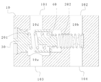
도 27 내지 도 29를 참조하면, 도 27은 본원의 제10 실시예에 따른 자동온도조절 밸브의 구조를 도시한 단면도로서, 제1 밸브 포트(B)가 개방되고 제2 밸브 포트(A)가 폐쇄된 상태를 나타내고, 도 28은 밸브 코어가 우측으로 이동된 후의 도 27의 자동온도조절 밸브의 개략도로서, 제2 밸브 포트(A)가 개방되고 제1 밸브 포트(B)가 폐쇄된 상태를 나타내며, 도 29는 도 27의 밸브 코어(40)의 개략도이다.27 to 29, FIG. 27 is a cross-sectional view showing the structure of the thermostatic valve according to the tenth embodiment of the present application, wherein the first valve port B is opened and the second valve port A is FIG. 28 is a schematic view of the thermostatic valve of FIG. 27 after the valve core is moved to the right, and the second valve port A is opened and the first valve port B is closed. 29 is a schematic diagram of the
이 실시예에서, 밸브 코어(40)는 밸브 캐비티(10a)를 따라 축 방향으로 이동 가능하고, 밸브 코어(40)의 일부는 밸브 캐비티(10a)의 내벽과 슬라이딩 결합된다. 제1 밸브 포트(B)는 밸브 캐비티(10a)의 단부 캐비티 벽, 즉 축 방향 캐비티 벽에 위치하고, 제2 밸브 포트(A)는 밸브 캐비티(10a)의 측면 캐비티 벽, 즉 반경방향 캐비티 벽에 위치한다. 이 해결책에서, 제1 유입구(103)와 제2 밸브 포트(A)는 서로 반대쪽이다. 구체적으로, 제1 유입구(103)를 밸브 캐비티(10a)와 연통시키는 유입구 통로(10e)는 제2 밸브 포트(A) 및 유출구 통로(10d)와 반대쪽이다. 이러한 방식으로, 제1 유입구(103)와 제1 유출구(101) 사이의 통로는 직선 통로이다. 도 28에 도시된 바와 같이, 제2 밸브 포트(A)가 개방될 때, 매체는 직선 통로를 통해 유출될 수 있고, 응답이 더 빠르다.In this embodiment, the
본 실시예의 밸브 코어(40)의 구조는 제3 실시예의 구조와 유사하다. 밸브 코어(40)는 제2 밸브 포트(A)를 차단하기 위한 제2 실링부로서 작용하는 슬리브 부분(402)을 포함한다. 메모리 스프링(201)은 슬리브 부분(402)에 구비되고 밸브 코어(40)와 단부 커버(30) 사이에 위치된다. 물론, 밸브 코어(40)를 다른 구조 또는 메모리 스프링(201)과 함께 사용함으로써 제2 밸브 포트(A)를 차단하는 것도 가능하다.The structure of the
또한, 제10 실시예에서, 슬리브 부분(402)의 개방 단부의 가장자리에 노치(402c)가 구비되어, 슬리브 부분(402) 내로 매체를 안내하기 위한 유동 안내 통로로서 기능한다. 도 27에 도시된 바와 같이, 슬리브 부분(402)이 제2 밸브 포트(A)를 차단하기 위해 사용될 때, 매체는 노치(402c)의 위치를 통해 슬리브 부분(402)에 들어갈 수 있고, 따라서 메모리 스프링(201)은 가열된 매체와 접촉하여 늦지 않게 변형될 수 있다. 유동 안내 통로는 도면에 도시된 노치(402c)로 한정되지 않으며, 예를 들어 슬리브 부분(402)의 측벽 또는 바닥에 제공될 수도 있음을 이해할 수 있다.Further, in the tenth embodiment, a notch 402c is provided at the edge of the open end of the
본 실시예의 유출구 통로(10d)와 유입구 통로(10e)는 반대로 배열되어 있음에 유의해야 한다. 슬리브 부분(402)이 밸브 캐비티(10a)의 내벽에 슬라이딩 결합될 때, 매체와 제1 밸브 포트(B) 사이의 통로를 막지 않기 위해, 도 27에서, 제2 밸브 포트(A)에 대응하는 슬리브 부분(402)의 외벽의 일부는 밸브 캐비티(10a)의 내벽과 슬라이딩 결합되고, 슬리브 부분(402)의 외벽에서 유입구 통로(10e) 및 제1 유입구(103)에 대응하는 부분과 밸브 캐비티(10a)의 내벽과의 사이에 간극이 구비되며, 이는 매체가 제1 밸브 포트(B)로 유동할 수 있도록 보장할 수 있다. 즉, 제2 실링부는 제2 밸브 포트(A)를 실링하기 위해서만 필요하고, 슬리브 부분(402)에서 유입구 통로(10e)와 대향하는 부분과 밸브 캐비티(10a)의 내벽 사이에 간극이 제공될 필요가 있다. 도 27에 도시된 바와 같이, 밸브 캐비티(10a)의 중심축은 밸브 코어(40)의 중심축으로부터 오프셋되고, 밸브 캐비티(10a)에서 유입구 통로(10e)에 대향하는 부분은 오목하다. 물론, 밸브 캐비티(10a)는 오목하지 않을 수 있고, 밸브 코어(40)는 축에 대하여 편심 구조로서 구비될 수 있음을 이해할 수 있다. 밸브 코어(40)의 일부가 밸브 캐비티(10a)의 내벽과 슬라이딩 결합되는 이러한 방식은 안정성 및 내충격성을 만족시킬 뿐만 아니라 유체 유동을 또한 촉진시킨다.It should be noted that the
또한, 본 실시예에서, 자동온도조절 밸브의 밸브 본체(10)에 2단계로 단차진 구멍이 형성되고, 가장 큰 구멍 밸브 캐비티(10a)이며, 중간 구멍과 가장 큰 구멍의 사이의 연결부에 제1 밸브 포트(B)가 형성된다. 이러한 방식으로, 제1 밸브 포트(B)를 차단하기 위해 이동하는 밸브 코어(40)의 행정이 단축될 수 있다. 물론, 상기 실시예에서와 같이 큰 구멍과 작은 구멍을 포함하는 단차진 구멍을 구비하는 것도 적용가능하다.In addition, in this embodiment, a stepped hole is formed in two stages in the
본 실시예에서 제2 유입구(102)와 제2 유출구(104)도 서로 반대쪽이며, 제2 유입구(102)와 제2 유출구(104) 사이에 직선 통로(10b)가 형성되고, 리턴 스프링(202)은 가장 작은 구멍을 관통하며 밸브 코어(40)와 직선 통로(10b)의 내벽 사이에서 압축된다. 직선 통로(10b)의 내벽에는 리턴 스프링(202)의 단부가 삽입될 수 있는 홈이 구비될 수 있다. 분명히, 리턴 스프링(202)의 단부는 밸브 캐비티(10a)의 단부 벽에서 압축될 수 있거나, 또는 가장 작은 구멍에 단차부가 제공될 수 있고, 리턴 스프링(202)의 단부는 단차부에서 또는 밸브 코어(40)에서 압축될 수 있다.In this embodiment, the
상기 실시예에서, 형성된 밸브 캐비티(10a)은 일 단부에 단부 포트를 갖는 캐비티이고, 단부 포트에 단부 커버(30)가 구비되며, 단부 커버(30)와 밸브 코어(40) 사이에 메모리 스프링(201)이 구비된다는 점에 유의해야 한다. 이 방법은 밸브 본체(10)를 기계 가공하여 밸브 캐비티(10a)를 형성하기에 편리하지만, 밸브 캐비티(10a)의 구조가 이에 한정되지 않는 것은 이해될 수 있다. 예를 들어, 주조 공정을 사용할 경우, 밸브 캐비티(10a)의 두 단부는 단부 포트를 갖지 않을 수 있고, 단부 커버는 구비되지 않는다. 그렇다면, (제1 실시예에서) 메모리 스프링(201) 및 리턴 스프링(202)은 밸브 캐비티(10a)의 캐비티 벽과 밸브 코어(40) 사이에 구비될 수 있다.In the above embodiment, the formed valve cavity 10a is a cavity having an end port at one end, an
2단계 단차부를 설정하는 목적이 메모리 스프링(201)의 특성을 사용하여 메모리 스프링(201)이 초기 위치로부터 가열, 팽창 및 변형 후 작동 위치로 전환되고 작동 위치에 유지되도록 하는 것임을 미리 설정된 개구도를 갖는 실시예로부터 알 수 있다. 따라서, 목적을 달성하기 위한 해결책은 2단계 단차부를 구비하는 것으로 한정되지 않는다. 예를 들어, 밸브 코어(40)의 단부에 환형 홈이 제공되고, 환형 홈에 메모리 스프링(201)의 단부가 제공되며, 온도가 상승한 후, 메모리 스프링(201)의 이 단부는 환형 홈으로부터 분리되고 작동 위치로서 다른 위치에 맞닿으며, 이는 또한 미리 설정된 초기 개방도를 설정하는 목적을 달성할 수 있다.The purpose of setting the two-step step is to use a characteristic of the
상기 실시예에서, 자동온도조절 밸브의 밸브 코어(40)의 이동을 제어하기 위한 제어 요소는 메모리 스프링(201)이다. 스프링이 열 액추에이터 주위에 둘러싸여있는 해결책과 비교할 때, 메모리 스프링(201)의 응답 시간이 더 빠르며, 매체를 다른 유로로 전환하기에 늦지 않게 제2 밸브 포트(A)가 개방될 수 있다. 냉각기와 변속기에 적용되면, 변속기의 성능을 향상시키고 변속기의 손상을 방지할 수 있다.In the above embodiment, the control element for controlling the movement of the
또한, 이 경우, 자동온도조절 밸브에 열 액추에이터가 추가로 구비될 필요가 없고, 구조가 간단하고 설치가 편리하여, 전체 자동온도조절 밸브가 더 가벼워지고 부피가 작아 질 수 있다.In addition, in this case, the thermostat valve does not need to be additionally provided with a thermal actuator, and the structure is simple and easy to install, so that the whole thermostat valve can be made lighter and smaller in volume.
상기 실시예에서, 예로서 밸브 본체(10)에는 제1 밸브 포트(B) 및 제2 밸브 포트(A)가 구비된다는 점에 유의해야 한다. 제2 밸브 포트(A)는 구비되지 않을 수 있음을, 즉 개폐 가능한 제2 밸브 포트(A)는 구비되지 않지만, 제1 유출구(101)와 밸브 캐비티(10a) 사이의 통로는 관통됨을 알 수 있다. 예를 들어 변속기와 냉각기에 적용하면, 제1 밸브 포트(B)가 폐쇄될 때, 매체(윤활유 등)는 냉각기로 바로 흐를 수 있다. 제1 밸브 포트(B)가 개방될 때, 제2 밸브 포트(A)가 없고 제1 유출구(101)와 연통하는 유출구 통로 만이 구비된다고 하더라도, 냉각기는 제1 유출구(101)와 연통하기 때문에, 제1 유출구(101)를 통한 유로의 유동저항은 제1 밸브 포트(B)를 통해 제2 유출구(104)로 바로 흐르는 유로의 유동 저항보다 더 클 것이다. 따라서, 매체는 대부분 제1 밸브 포트(B)를 통해 제2 유출구(104)로 흐를 것이다. 물론, 제2 밸브 포트(A)를 제공하고 제2 밸브 포트(A)와 제1 밸브 포트(B)의 개폐 상태를 전환함으로써, 상이한 요구 사항에 따라 매체의 유로를 보다 명확하게 분배하고 시스템 내부 누출을 줄일 수 있다.It should be noted that in the above embodiment, as an example, the
또한, 제2 밸브 포트(A)가 구비되지 않을 때, 초기 위치 및 작동 위치가 있는 상기 실시예에서, 메모리 스프링(201)이 초기 위치에 있을 때, 제1 밸브 포트(B)가 폐쇄되어, 윤활유가 제1 유출구(101)로부터 냉각기로 직접 유입되어 초기 상태에서 윤활유를 채울 수 있도록 하는 방식으로 설계될 수 있다. 동시에, 제2 유입구(102)가 제공되어야 하고, 제1 밸브 포트(B)는 또한 제2 유입구(102)와 연통되어, 제2 유입구(102)로부터 유입되는 윤활유가 또한 제1 밸브 포트(B)와 변속기 사이의 통로를 채워서, 전체 시스템의 오일 충전 과정을 완료할 수 있다.Further, when the second valve port A is not provided, in the above embodiment having the initial position and the operating position, when the
제2 밸브 포트(A)가 구비될 때, 제1 밸브 포트(B)는 상기 실시예에서 설명된 바와 같이 미리 설정된 개방도를 가질 수 있고, 또한 폐쇄될 수도 있다. 제1 밸브 포트(B)가 폐쇄될 때, 자동온도조절 밸브의 밸브 본체(10)에는 바람직하게는 제2 유출구(104)와 연통하는 제2 유입구(102)가 또한 구비되어, 제2 유입구(102)로부터 유입되는 윤활유가 제1 밸브 포트(B)와 변속기 사이의 통로를 또한 채울 수 있다. 물론, 제1 밸브 포트(B)가 초기 위치에서 미리 설정된 개방도를 갖는 경우, 제1 밸브 포트(B)와 변속기 사이의 통로는 채워질 수 있다. 해결책은 밸브 본체(10)에 제2 유입구(102)를 구비하는 것으로 한정되지 않으며, 냉각기의 유출구는 다른 통로들을 통해서 변속기에 연결될 수도 있다.When the second valve port A is provided, the first valve port B may have a preset opening degree as described in the above embodiment, and may also be closed. When the first valve port (B) is closed, the
제2 밸브 포트(A)가 구비되는지 여부에 관계없이, 초기 상태에서 냉각기를 채우는 것을 용이하게 하기 위해, 다음과 같이 설정될 수 있다. 즉, 메모리 스프링(201)이 초기 위치에 있을 때 밸브 코어(40)와 제1 밸브 포트(B) 사이의 거리는 메모리 스프링이 작동 위치에 있고 온도가 특정 값보다 낮을 때 밸브 코어(40)와 제1 밸브 포트(B) 사이의 거리보다 작다. 이러한 방식으로, 메모리 스프링(201)이 특정 값을 갖는 온도보다 낮을 때, 메모리 스프링(201)의 길이가 변화하여, 제1 밸브 포트(B) 및/또는 제2 밸브 포트(A)는 초기 위치와 작동 위치에서 상이한 개방도를 갖도록 조정될 수 있다.Regardless of whether or not the second valve port A is provided, it can be set as follows to facilitate filling the cooler in the initial state. That is, when the
상기 실시예는 본원의 바람직한 실시예일 뿐이다. 통상의 기술자라면, 본원의 원리를 벗어나지 않고 본원에 대한 몇몇 수정 및 개선이 이루어질 수 있으며, 이러한 수정 및 개선은 또한 본원의 보호범위 내에 있는 것으로 간주된다는 점에 유의해야 한다.The above embodiments are only preferred embodiments herein. It should be noted by those skilled in the art that some modifications and improvements to the present application can be made without departing from the principles of the present application, and such modifications and improvements are also considered to be within the scope of protection herein.
10: 밸브 본체
10a: 밸브 캐비티
10b: 직선 통로
10c: 작은 구멍
10d: 유출구 통로
10e: 유입구 통로
B: 제1 밸브 포트
A: 제2 밸브 포트
101: 제1 유출구
102: 제2 유입구
103: 제1 유입구
104: 제2 유출구
201: 메모리 스프링
202: 리턴 스프링
30: 단부 커버
301: 제1 단차면
302: 제2 단차면
40: 밸브 코어
401: 본체부
401a: 단부 돌출 플랫폼
402: 슬리브 부분
402a: 안내 유입구
402b: 개구
402c: 노치
403: 안내 로드
405: 실링판
405a: 오목 구멍
404: 구형부
40': 실링편
50: 외부 커넥터
60: 밸브 스템10: valve body
10a: valve cavity
10b: straight path
10c: eyelet
10d: outlet passage
10e: inlet passage
B: 1st valve port
A: Second valve port
101: first outlet
102: second inlet
103: first inlet
104: second outlet
201: memory spring
202: return spring
30: end cover
301: first step
302: second step
40: valve core
401: main body
401a: End protruding platform
402: sleeve part
402a: guide inlet
402b: opening
402c: Notch
403: guide rod
405: sealing plate
405a: concave hole
404: spherical part
40': Ceiling
50: external connector
60: valve stem
Claims (12)
단부 커버, 밸브 본체 및 상기 밸브 본체의 밸브 캐비티에 위치한 밸브 코어를 포함하고, 상기 자동온도조절 밸브는 제1 유출구, 제2 유출구 및 상기 밸브 캐비티와 연통하는 제1 유입구를 가지며, 상기 밸브 본체에는 상기 밸브 캐비티를 상기 제2 유출구와 연통시키도록 구성된 제1 밸브 포트가 추가로 구비되고, 상기 밸브 코어의 이동 중에 상기 밸브 코어는 상기 제1 밸브 포트를 개폐하도록 구성되며,
상기 밸브 캐비티에는 리턴 스프링 및 메모리 스프링이 추가로 구비되고, 상기 메모리 스프링은 메모리 합금으로 제조되며, 상기 리턴 스프링은 복귀력을 제공하여 상기 밸브 코어가 상기 제1 밸브 포트를 개방하게 하도록 구성되고, 상기 메모리 스프링은 일 단부가 상기 밸브 코어의 일 단부와 접촉하고, 다른 일 단부가 상기 단부 커버와 접촉하며, 온도가 특정 값으로 상승할 때, 상기 메모리 스프링은 탄성력을 발생시켜 상기 밸브 코어를 복귀력에 대항하여 이동하도록 구동함으로써 상기 제1 밸브 포트를 폐쇄하도록 구성되고, 그리고
상기 제1 유입구는 상기 밸브 본체의 측벽에 구비되는, 자동온도조절 밸브.As a thermostatic valve,
An end cover, a valve body, and a valve core located in a valve cavity of the valve body, wherein the thermostatic valve has a first outlet, a second outlet, and a first inlet communicating with the valve cavity, wherein the valve body includes A first valve port configured to communicate the valve cavity with the second outlet is further provided, and the valve core is configured to open and close the first valve port during movement of the valve core,
A return spring and a memory spring are further provided in the valve cavity, the memory spring is made of a memory alloy, and the return spring is configured to provide a return force so that the valve core opens the first valve port, When the memory spring has one end contacting one end of the valve core, the other end contacting the end cover, and when the temperature rises to a specific value, the memory spring generates elastic force to return the valve core. Configured to close the first valve port by driving to move against a force, and
The first inlet is provided on the side wall of the valve body, thermostatic valve.
상기 자동온도조절 밸브에는 제2 밸브 포트가 추가로 구비되고, 상기 제2 밸브 포트는 상기 밸브 캐비티의 측면 캐비티 벽에 구비되며, 상기 밸브 코어는 상기 제1 밸브 포트를 차단하기 위한 제1 실링부와, 상기 제2 밸브 포트를 차단하기 위한 제2 실링부를 포함하고, 상기 밸브 코어에는 슬리브 부분이 구비되며, 상기 메모리 스프링의 일 단부는 상기 슬리브 부분의 개방 단부로부터 상기 슬리브 부분 내로 연장되고, 상기 슬리브 부분의 적어도 일부는 상기 밸브 캐비티의 내벽과 슬라이딩 결합되며, 그리고
상기 제2 실링부는 상기 슬리브 부분의 일부에 의해 형성되고, 상기 슬리브 부분의 외벽 중 상기 제2 밸브 포트에 대응하는 부분은 상기 제2 밸브 포트를 차단하도록 구성되는, 자동온도조절 밸브.According to claim 1,
The thermostatic valve is further provided with a second valve port, the second valve port is provided on the side cavity wall of the valve cavity, and the valve core is a first sealing portion for blocking the first valve port And a second sealing portion for blocking the second valve port, wherein the valve core is provided with a sleeve portion, and one end of the memory spring extends from the open end of the sleeve portion into the sleeve portion, and At least a portion of the sleeve portion is slidingly engaged with the inner wall of the valve cavity, and
The second sealing portion is formed by a portion of the sleeve portion, the portion of the outer wall of the sleeve portion corresponding to the second valve port is configured to block the second valve port, thermostatic valve.
상기 밸브 코어 또는 상기 단부 커버에는 초기 위치 및 작동 위치가 구비되며, 상기 메모리 스프링의 적어도 하나의 단부는 상기 단부 커버의 초기 위치 또는 상기 밸브 코어의 초기 위치에 위치하며, 상기 메모리 스프링이 초기 위치에 있을 때, 상기 제1 밸브 포트는 폐쇄 상태이고, 상기 제2 밸브 포트는 개방 상태이며, 상기 제2 밸브 포트는 미리 설정된 개방도를 가지고, 상기 메모리 스프링의 온도가 상기 특정 값으로 가열되고 상기 메모리 스프링이 변형된 후, 상기 메모리 스프링의 일 단부는 초기 위치로부터 분리되어 작동 위치에 있고 작동 위치에 유지되도록 구성되며, 그리고
작동 위치에서, 온도가 상기 특정 값으로 상승할 때, 상기 메모리 스프링은 탄성력을 발생시켜 상기 밸브 코어를 복귀력에 대항하여 이동하도록 구동함으로써 상기 제1 밸브 포트를 폐쇄하도록 구성되고, 상기 메모리 스프링의 온도가 상기 특정 값 아래로 저하된 후에는, 상기 메모리 스프링은 탄성 특성을 상실하고, 상기 리턴 스프링은 상기 밸브 코어를 구동하여 상기 제1 밸브 포트를 개방하도록 구성되는, 자동온도조절 밸브.The method according to claim 1 or 2,
The valve core or the end cover is provided with an initial position and an operating position, and at least one end of the memory spring is located in an initial position of the end cover or an initial position of the valve core, and the memory spring is in an initial position. When present, the first valve port is closed, the second valve port is open, the second valve port has a preset opening degree, the temperature of the memory spring is heated to the specific value and the memory After the spring is deformed, one end of the memory spring is configured to be in an operating position and held in an operating position separated from the initial position, and
In the operating position, when the temperature rises to the specified value, the memory spring is configured to close the first valve port by generating an elastic force to drive the valve core to move against the return force, and After the temperature is lowered below the specified value, the memory spring loses elasticity, and the return spring is configured to open the first valve port by driving the valve core.
상기 밸브 코어는 본체부분을 포함하고, 상기 본체부분은 상기 슬리브 부분 내로 연장되는 일 단부를 가지며 단부 돌출 플랫폼을 구비하고, 상기 밸브 코어에는 제1 단차부 및 상기 제1 단차부의 외경보다 큰 외경을 갖는 제2 단차부를 포함하는 2단계 단차부가 구비되며, 상기 제1 단차부는 상기 단부 돌출 플랫폼에 의해 형성되고, 상기 제2 단차부는 상기 슬리브 부분의 바닥에 의해 형성되며, 제1 단차면의 위치는 초기 위치이고, 제2 단차면의 위치는 작동 위치이며, 초기 위치에서 상기 밸브 코어와 상기 제1 밸브 포트 사이의 거리는 작동 위치에서 상기 밸브 코어와 상기 제1 밸브 포트 사이의 거리보다 큰, 자동온도조절 밸브.According to claim 3,
The valve core includes a body portion, the body portion has one end extending into the sleeve portion, and has an end protruding platform, wherein the valve core has an outer diameter larger than the outer diameter of the first step portion and the first step portion. A two-step step portion including a second step portion is provided, the first step portion is formed by the end protruding platform, the second step portion is formed by the bottom of the sleeve portion, and the position of the first step surface is The automatic temperature is the initial position, the position of the second step surface is the operating position, and the distance between the valve core and the first valve port in the initial position is greater than the distance between the valve core and the first valve port in the operating position. Regulating valve.
상기 단부 커버에는 제1 단차부 및 상기 제1 단차부의 외경보다 큰 외경을 갖는 제2 단차부를 포함하는 2단계 단차부가 구비되며, 제1 단차면의 위치는 초기 위치이고, 제2 단차면의 위치는 작동 위치이며, 초기 위치와 상기 제1 밸브 포트 사이의 거리는 작동 위치와 상기 제1 밸브 포트 사이의 거리보다 작은, 자동온도조절 밸브.According to claim 3,
The end cover is provided with a second stepped portion including a first stepped portion and a second stepped portion having an outer diameter larger than the outer diameter of the first stepped portion. Is an operating position, the distance between the initial position and the first valve port is less than the distance between the operating position and the first valve port, thermostatic valve.
상기 슬리브 부분 중 상기 제1 유입구와 대향하는 부분과 상기 밸브 캐비티의 내벽 사이에 간극이 구비되고, 상기 밸브 캐비티를 상기 슬리브 부분의 내부 캐비티와 연통시키기 위한 유동 안내 통로가 상기 슬리브 부분의 상기 외벽과 상기 밸브 캐비티의 상기 내벽 사이에 구비되는, 자동온도조절 밸브.The method according to any one of claims 2 to 5,
A gap is provided between a portion of the sleeve portion facing the first inlet and an inner wall of the valve cavity, and a flow guide passage for communicating the valve cavity with an inner cavity of the sleeve portion is in contact with the outer wall of the sleeve portion. A thermostatic valve provided between the inner walls of the valve cavity.
상기 슬리브 부분의 상기 개방 단부의 가장자리에 적어도 하나의 노치가 구비되고, 상기 유동 안내 통로는 상기 적어도 하나의 노치에 의해 형성되는, 자동온도조절 밸브.The method of claim 6,
At least one notch is provided at an edge of the open end of the sleeve portion, and the flow guide passage is formed by the at least one notch, thermostatic valve.
상기 슬리브 부분의 상기 바닥에 안내 유입구가 구비되고, 상기 안내 유입구는 상기 밸브 캐비티를 상기 슬리브 부분의 내부 캐비티와 연통시키기 위한 유동 안내 통로인, 자동온도조절 밸브.The method according to any one of claims 2 to 5,
A thermostatic valve is provided at the bottom of the sleeve portion, and the guide inlet is a flow guide passage for communicating the valve cavity with the inner cavity of the sleeve portion.
상기 자동온도조절 밸브는 상기 제2 유출구와 연통하는 제2 유입구를 더 포함하고, 상기 제1 유출구, 상기 제2 유입구, 상기 제2 유출구 및 상기 제1 유입구는 모두 상기 밸브 본체의 상기 측벽에 구비되며, 상기 제2 유출구와 상기 제2 유입구는 서로 대향하고, 상기 제2 유출구와 제2 유입구 사이에는 직선 통로가 형성되며, 상기 제1 밸브 포트는 상기 직선 통로와 연통되는, 자동온도조절 밸브.The method of claim 8,
The thermostatic valve further includes a second inlet communicating with the second outlet, and the first outlet, the second inlet, the second outlet, and the first inlet are all provided on the side wall of the valve body. And, the second outlet and the second inlet are opposite to each other, a straight passage is formed between the second outlet and the second inlet, the first valve port is in communication with the straight passage, thermostatic valve.
상기 자동온도조절 밸브는 상기 제2 유출구와 연통하는 제2 유입구를 더 포함하며, 상기 제1 유출구 및 상기 제2 유입구는 각각 냉각기의 유입구 및 유출구에 연결되고, 상기 제1 유입구 및 상기 제2 유출구는 각각 변속기의 유입구 및 유출구에 연결되는, 자동온도조절 밸브.The method of claim 8,
The thermostatic valve further includes a second inlet communicating with the second outlet, and the first outlet and the second inlet are respectively connected to the inlet and outlet of the cooler, and the first inlet and the second outlet Is a thermostatic valve, which is connected to the inlet and outlet of the transmission, respectively.
상기 밸브 본체에는 단차진 구멍이 형성되고, 상기 단차진 구멍 중 큰 구멍은 상기 밸브 캐비티이며, 상기 제1 밸브 포트는 상기 단차진 구멍의 큰 구멍과 작은 구멍의 연결부에 형성되고, 상기 제1 실링부에 안내 로드가 연결되며, 상기 안내 로드는 상기 작은 구멍에 삽입되고 상기 작은 구멍의 내벽과 슬라이딩 결합되어 상기 밸브 코어의 이동을 안내하는, 자동온도조절 밸브.The method of claim 7 to claim 10,
A stepped hole is formed in the valve body, and a larger hole among the stepped holes is the valve cavity, and the first valve port is formed at a connection between a large hole and a small hole in the stepped hole, and the first sealing The guide rod is connected to the portion, the guide rod is inserted into the small hole and slidingly coupled to the inner wall of the small hole to guide the movement of the valve core, thermostatic valve.
단부 커버, 밸브 본체 및 상기 밸브 본체의 밸브 캐비티에 위치한 밸브 코어를 포함하고, 상기 자동온도조절 밸브는 제1 유출구, 제2 유출구, 상기 제2 유출구와 연통하는 제2 유입구 및 상기 밸브 캐비티와 연통하는 제1 유입구를 가지며, 상기 밸브 본체에는 상기 밸브 캐비티를 상기 제2 유출구와 연통시키도록 구성된 제1 밸브 포트가 추가로 구비되고, 상기 밸브 코어의 이동 중에 상기 밸브 코어는 상기 제1 밸브 포트를 개폐하도록 구성되며,
상기 밸브 캐비티에는 리턴 스프링 및 메모리 스프링이 추가로 구비되고, 상기 메모리 스프링은 메모리 합금으로 제조되며, 상기 리턴 스프링은 복귀력을 제공하여 상기 밸브 코어가 상기 제1 밸브 포트를 개방하게 하도록 구성되고,
상기 밸브 본체, 상기 밸브 코어 및 상기 단부 커버 중 적어도 하나에는 초기 위치 및 작동 위치가 구비되며, 상기 메모리 스프링의 적어도 하나의 단부는 상기 밸브 본체 또는 상기 밸브 코어 또는 상기 단부 커버의 초기 위치에 위치하며, 상기 메모리 스프링의 온도가 특정 값으로 가열되고 상기 메모리 스프링이 변형된 후, 상기 메모리 스프링의 상기 일 단부는 초기 위치로부터 분리되어 작동 위치에 유지되도록 구성되며, 그리고
상기 메모리 스프링이 초기 위치에 있을 때, 상기 제1 밸브 포트는 폐쇄되고, 상기 메모리 스프링이 초기 위치에 있을 때 상기 밸브 코어와 상기 제1 밸브 포트 사이의 거리는 상기 메모리 스프링이 작동 위치에 있고 온도가 특정 값 아래일 때 상기 밸브 코어와 상기 제1 밸브 포트 사이의 거리보다 작으며,
상기 메모리 스프링이 작동 위치에 있고 온도가 상기 특정 값으로 상승할 때, 상기 메모리 스프링은 탄성력을 발생시켜 상기 밸브 코어를 복귀력에 대항하여 이동하도록 구동함으로써 상기 제1 밸브 포트를 폐쇄하도록 구성되고, 상기 메모리 스프링의 온도가 상기 특정 값 아래로 저하된 후에는, 상기 메모리 스프링은 탄성 특성을 상실하고, 상기 리턴 스프링은 상기 밸브 코어를 구동하여 상기 제1 밸브 포트를 개방하도록 구성되는, 자동온도조절 밸브.As a thermostatic valve,
An end cover, a valve body, and a valve core located in a valve cavity of the valve body, wherein the thermostatic valve is in communication with a first outlet, a second outlet, a second inlet communicating with the second outlet, and the valve cavity The valve body is further provided with a first valve port configured to communicate the valve cavity with the second outlet, wherein the valve core is configured to communicate with the first valve port during movement of the valve core. It is configured to open and close,
A return spring and a memory spring are further provided in the valve cavity, the memory spring is made of a memory alloy, and the return spring is configured to provide a return force so that the valve core opens the first valve port,
At least one of the valve body, the valve core and the end cover is provided with an initial position and an operating position, and at least one end of the memory spring is located at an initial position of the valve body or the valve core or the end cover, , After the temperature of the memory spring is heated to a certain value and the memory spring is deformed, the one end of the memory spring is configured to be separated from the initial position and maintained in an operating position, and
When the memory spring is in the initial position, the first valve port is closed, and when the memory spring is in the initial position, the distance between the valve core and the first valve port is the memory spring in the operating position and the temperature Less than a distance between the valve core and the first valve port when below a certain value,
When the memory spring is in the operating position and the temperature rises to the specified value, the memory spring is configured to close the first valve port by generating an elastic force to drive the valve core to move against the return force, After the temperature of the memory spring is lowered below the specific value, the memory spring loses elasticity, and the return spring is configured to open the first valve port by driving the valve core. valve.
Applications Claiming Priority (5)
| Application Number | Priority Date | Filing Date | Title |
|---|---|---|---|
| CN201711116965.7 | 2017-11-13 | ||
| CN201711116965.7A CN109780260B (en) | 2017-11-13 | 2017-11-13 | Temperature regulating valve |
| CN201711115307.6A CN109780259B (en) | 2017-11-13 | 2017-11-13 | Temperature regulating valve |
| CN201711115307.6 | 2017-11-13 | ||
| PCT/CN2018/115136 WO2019091481A1 (en) | 2017-11-13 | 2018-11-13 | Thermostatic valve |
Publications (2)
| Publication Number | Publication Date |
|---|---|
| KR20200085329A true KR20200085329A (en) | 2020-07-14 |
| KR102297792B1 KR102297792B1 (en) | 2021-09-03 |
Family
ID=66437590
Family Applications (1)
| Application Number | Title | Priority Date | Filing Date |
|---|---|---|---|
| KR1020207016769A KR102297792B1 (en) | 2017-11-13 | 2018-11-13 | thermostatic valve |
Country Status (5)
| Country | Link |
|---|---|
| US (1) | US20200293071A1 (en) |
| EP (1) | EP3712466A4 (en) |
| KR (1) | KR102297792B1 (en) |
| CN (1) | CN110799776B (en) |
| WO (1) | WO2019091481A1 (en) |
Families Citing this family (1)
| Publication number | Priority date | Publication date | Assignee | Title |
|---|---|---|---|---|
| CN109695703B (en) * | 2017-10-23 | 2021-02-02 | 浙江三花汽车零部件有限公司 | Heat exchange device |
Citations (10)
| Publication number | Priority date | Publication date | Assignee | Title |
|---|---|---|---|---|
| US4190198A (en) * | 1978-04-12 | 1980-02-26 | Lockhart Industries, Inc. | Oil cooler bypass valve actuating means |
| KR20110086370A (en) * | 2010-01-22 | 2011-07-28 | 김순자 | Temperature control valve with shape memory alloy spring |
| CN202360800U (en) * | 2011-11-24 | 2012-08-01 | 北京龙浩安达新技术有限公司 | Switching valve and heating system |
| CN202371214U (en) * | 2011-11-24 | 2012-08-08 | 北京龙浩安达新技术有限公司 | Cold-hot switching mixing valve |
| US20130042927A1 (en) * | 2011-08-19 | 2013-02-21 | GM Global Technology Operations LLC | Valve configured for regulating the flow of fluid from a transmission to a fluid cooler |
| KR20140111452A (en) * | 2013-03-11 | 2014-09-19 | 이재흥 | Automatic temperature control valve with shape memory alloy srping |
| CN104595526A (en) * | 2015-01-14 | 2015-05-06 | 苏州西脉记忆合金有限公司 | Memory alloy constant-temperature water faucet |
| CN104847874A (en) * | 2014-02-14 | 2015-08-19 | 通用汽车环球科技运作有限责任公司 | Thermal bypass valve using shape memory alloys |
| KR20170043123A (en) * | 2015-10-12 | 2017-04-21 | 주식회사 유니크 | Bypass valve and bypass valve assembly having the same |
| CN107304834A (en) * | 2016-04-21 | 2017-10-31 | 浙江三花汽车零部件有限公司 | A kind of temperature control system |
Family Cites Families (10)
| Publication number | Priority date | Publication date | Assignee | Title |
|---|---|---|---|---|
| US5746170A (en) * | 1995-11-16 | 1998-05-05 | Ginko Bussan Co., Ltd. | Engine oil block for use in routing oil to an oil cooler |
| US6497372B2 (en) * | 2000-12-07 | 2002-12-24 | Jae-Heung Lee | Automatic temperature control valve |
| DE10261180A1 (en) * | 2002-12-20 | 2004-07-01 | Daimlerchrysler Ag | Temperature-controlled oil spray nozzle for piston cooling |
| US6742716B1 (en) * | 2003-02-28 | 2004-06-01 | Standard-Thomson Corporation | Thermostat |
| DE102006039554A1 (en) * | 2006-08-23 | 2008-03-06 | Zf Friedrichshafen Ag | Bypass valve for a hydraulic unit downstream cooler |
| US9188031B2 (en) * | 2009-12-07 | 2015-11-17 | Tbk Co., Ltd. | Engine lubricating oil supply device |
| US9200713B2 (en) * | 2011-12-02 | 2015-12-01 | GM Global Technology Operations LLC | Valve configured for regulating the flow of fluid from a transmission to a cooler |
| CN103791664B (en) * | 2012-10-31 | 2016-09-14 | 浙江三花股份有限公司 | A kind of with the heating power expansion valve being unidirectionally controlled function |
| US20160047459A1 (en) * | 2015-10-30 | 2016-02-18 | Air International Thermal Systems R & D (Shanghai) Co., Ltd | Temperature-regulating Valve of Transmission Oil Cooling System in A Passenger Car |
| CN107304844B (en) * | 2016-04-21 | 2019-08-23 | 浙江三花汽车零部件有限公司 | A kind of thermosistor and a kind of temperature control system |
-
2018
- 2018-11-13 US US16/761,487 patent/US20200293071A1/en not_active Abandoned
- 2018-11-13 WO PCT/CN2018/115136 patent/WO2019091481A1/en unknown
- 2018-11-13 CN CN201880040434.0A patent/CN110799776B/en active Active
- 2018-11-13 KR KR1020207016769A patent/KR102297792B1/en active IP Right Grant
- 2018-11-13 EP EP18877273.5A patent/EP3712466A4/en active Pending
Patent Citations (10)
| Publication number | Priority date | Publication date | Assignee | Title |
|---|---|---|---|---|
| US4190198A (en) * | 1978-04-12 | 1980-02-26 | Lockhart Industries, Inc. | Oil cooler bypass valve actuating means |
| KR20110086370A (en) * | 2010-01-22 | 2011-07-28 | 김순자 | Temperature control valve with shape memory alloy spring |
| US20130042927A1 (en) * | 2011-08-19 | 2013-02-21 | GM Global Technology Operations LLC | Valve configured for regulating the flow of fluid from a transmission to a fluid cooler |
| CN202360800U (en) * | 2011-11-24 | 2012-08-01 | 北京龙浩安达新技术有限公司 | Switching valve and heating system |
| CN202371214U (en) * | 2011-11-24 | 2012-08-08 | 北京龙浩安达新技术有限公司 | Cold-hot switching mixing valve |
| KR20140111452A (en) * | 2013-03-11 | 2014-09-19 | 이재흥 | Automatic temperature control valve with shape memory alloy srping |
| CN104847874A (en) * | 2014-02-14 | 2015-08-19 | 通用汽车环球科技运作有限责任公司 | Thermal bypass valve using shape memory alloys |
| CN104595526A (en) * | 2015-01-14 | 2015-05-06 | 苏州西脉记忆合金有限公司 | Memory alloy constant-temperature water faucet |
| KR20170043123A (en) * | 2015-10-12 | 2017-04-21 | 주식회사 유니크 | Bypass valve and bypass valve assembly having the same |
| CN107304834A (en) * | 2016-04-21 | 2017-10-31 | 浙江三花汽车零部件有限公司 | A kind of temperature control system |
Also Published As
| Publication number | Publication date |
|---|---|
| CN110799776A (en) | 2020-02-14 |
| US20200293071A1 (en) | 2020-09-17 |
| KR102297792B1 (en) | 2021-09-03 |
| EP3712466A4 (en) | 2021-07-14 |
| CN110799776B (en) | 2024-04-09 |
| EP3712466A1 (en) | 2020-09-23 |
| WO2019091481A1 (en) | 2019-05-16 |
Similar Documents
| Publication | Publication Date | Title |
|---|---|---|
| WO2014119048A1 (en) | Thermo valve | |
| EP3059405B1 (en) | Thermostatic valve | |
| EP2444703B1 (en) | Thermal valve | |
| KR102380176B1 (en) | Oil temperature control system for valve assembly, heat exchange assembly, and gearbox | |
| CN109780260B (en) | Temperature regulating valve | |
| KR20180120236A (en) | Thermostatic valve | |
| KR20200051793A (en) | Heat exchanger | |
| US10302208B2 (en) | Control valve with external relief bias member | |
| KR20180111937A (en) | Thermostat and temperature control system | |
| CN108087530B (en) | Heat exchange assembly | |
| KR102288080B1 (en) | System, heat exchange assembly and valve assembly for regulating the temperature of transmission oil | |
| KR102297792B1 (en) | thermostatic valve | |
| EP3812633B1 (en) | Temperature adjusting valve | |
| CN109780310B (en) | Temperature regulating valve | |
| CN109780259B (en) | Temperature regulating valve | |
| CN108087532B (en) | Heat exchange assembly | |
| CN108087531B (en) | Heat exchange assembly | |
| CN109780258B (en) | Temperature regulating valve | |
| CN109780261B (en) | Temperature regulating valve | |
| CN108087579B (en) | Valve assembly | |
| CN112747167B (en) | Temperature regulating valve | |
| KR20180070364A (en) | Thermostat having improved reactivity | |
| CN109780187A (en) | Heat control valve | |
| JPH10318426A (en) | Flow control valve |
Legal Events
| Date | Code | Title | Description |
|---|---|---|---|
| E902 | Notification of reason for refusal | ||
| E701 | Decision to grant or registration of patent right | ||
| GRNT | Written decision to grant |