KR20200084699A - Apparatus and Method for measuring distance using SPAD(Single Photon Avalanche Diode) using TOF(Time of Flight) - Google Patents
Apparatus and Method for measuring distance using SPAD(Single Photon Avalanche Diode) using TOF(Time of Flight) Download PDFInfo
- Publication number
- KR20200084699A KR20200084699A KR1020190000868A KR20190000868A KR20200084699A KR 20200084699 A KR20200084699 A KR 20200084699A KR 1020190000868 A KR1020190000868 A KR 1020190000868A KR 20190000868 A KR20190000868 A KR 20190000868A KR 20200084699 A KR20200084699 A KR 20200084699A
- Authority
- KR
- South Korea
- Prior art keywords
- time
- light
- light reception
- tof
- reference time
- Prior art date
Links
- 238000000034 method Methods 0.000 title claims description 30
- 230000003287 optical effect Effects 0.000 claims abstract description 19
- 238000001514 detection method Methods 0.000 claims description 7
- 230000001678 irradiating effect Effects 0.000 claims description 4
- 230000004044 response Effects 0.000 claims description 2
- 238000010586 diagram Methods 0.000 description 6
- 238000012545 processing Methods 0.000 description 6
- 230000008569 process Effects 0.000 description 5
- 238000005516 engineering process Methods 0.000 description 4
- 230000006870 function Effects 0.000 description 3
- 238000000691 measurement method Methods 0.000 description 3
- 238000005259 measurement Methods 0.000 description 2
- 102100034112 Alkyldihydroxyacetonephosphate synthase, peroxisomal Human genes 0.000 description 1
- 101000799143 Homo sapiens Alkyldihydroxyacetonephosphate synthase, peroxisomal Proteins 0.000 description 1
- 238000000848 angular dependent Auger electron spectroscopy Methods 0.000 description 1
- 230000003190 augmentative effect Effects 0.000 description 1
- 230000008859 change Effects 0.000 description 1
- 238000004891 communication Methods 0.000 description 1
- 238000007796 conventional method Methods 0.000 description 1
- 230000000694 effects Effects 0.000 description 1
- 230000010354 integration Effects 0.000 description 1
- 238000004519 manufacturing process Methods 0.000 description 1
- 230000007246 mechanism Effects 0.000 description 1
- 230000035484 reaction time Effects 0.000 description 1
- 230000035945 sensitivity Effects 0.000 description 1
- 230000008685 targeting Effects 0.000 description 1
- 238000002366 time-of-flight method Methods 0.000 description 1
- 230000001960 triggered effect Effects 0.000 description 1
- XLYOFNOQVPJJNP-UHFFFAOYSA-N water Substances O XLYOFNOQVPJJNP-UHFFFAOYSA-N 0.000 description 1
Images


Classifications
-
- G—PHYSICS
- G01—MEASURING; TESTING
- G01S—RADIO DIRECTION-FINDING; RADIO NAVIGATION; DETERMINING DISTANCE OR VELOCITY BY USE OF RADIO WAVES; LOCATING OR PRESENCE-DETECTING BY USE OF THE REFLECTION OR RERADIATION OF RADIO WAVES; ANALOGOUS ARRANGEMENTS USING OTHER WAVES
- G01S7/00—Details of systems according to groups G01S13/00, G01S15/00, G01S17/00
- G01S7/48—Details of systems according to groups G01S13/00, G01S15/00, G01S17/00 of systems according to group G01S17/00
- G01S7/483—Details of pulse systems
- G01S7/486—Receivers
- G01S7/4861—Circuits for detection, sampling, integration or read-out
-
- G—PHYSICS
- G01—MEASURING; TESTING
- G01S—RADIO DIRECTION-FINDING; RADIO NAVIGATION; DETERMINING DISTANCE OR VELOCITY BY USE OF RADIO WAVES; LOCATING OR PRESENCE-DETECTING BY USE OF THE REFLECTION OR RERADIATION OF RADIO WAVES; ANALOGOUS ARRANGEMENTS USING OTHER WAVES
- G01S17/00—Systems using the reflection or reradiation of electromagnetic waves other than radio waves, e.g. lidar systems
- G01S17/02—Systems using the reflection of electromagnetic waves other than radio waves
- G01S17/06—Systems determining position data of a target
- G01S17/08—Systems determining position data of a target for measuring distance only
- G01S17/10—Systems determining position data of a target for measuring distance only using transmission of interrupted, pulse-modulated waves
-
- G—PHYSICS
- G01—MEASURING; TESTING
- G01S—RADIO DIRECTION-FINDING; RADIO NAVIGATION; DETERMINING DISTANCE OR VELOCITY BY USE OF RADIO WAVES; LOCATING OR PRESENCE-DETECTING BY USE OF THE REFLECTION OR RERADIATION OF RADIO WAVES; ANALOGOUS ARRANGEMENTS USING OTHER WAVES
- G01S7/00—Details of systems according to groups G01S13/00, G01S15/00, G01S17/00
- G01S7/48—Details of systems according to groups G01S13/00, G01S15/00, G01S17/00 of systems according to group G01S17/00
- G01S7/481—Constructional features, e.g. arrangements of optical elements
- G01S7/4816—Constructional features, e.g. arrangements of optical elements of receivers alone
-
- G—PHYSICS
- G01—MEASURING; TESTING
- G01J—MEASUREMENT OF INTENSITY, VELOCITY, SPECTRAL CONTENT, POLARISATION, PHASE OR PULSE CHARACTERISTICS OF INFRARED, VISIBLE OR ULTRAVIOLET LIGHT; COLORIMETRY; RADIATION PYROMETRY
- G01J1/00—Photometry, e.g. photographic exposure meter
- G01J1/42—Photometry, e.g. photographic exposure meter using electric radiation detectors
- G01J1/44—Electric circuits
- G01J2001/4446—Type of detector
- G01J2001/446—Photodiode
- G01J2001/4466—Avalanche
Abstract
Description
본 개시는 TOF(Time of Flight)을 이용하여 거리를 측정하는 장치 및 방법에 관한 것이다.The present disclosure relates to an apparatus and method for measuring a distance using a time of flight (TOF).
TOF(Time of Flight: TOF) 기술은 센서 내에 또는 센서 근처에 배치된 광원에서 펄스(pulse) 형태의 광을 조사한 후 반사된 광을 수광하여 그 사이의 시간을 측정한 후 광속 불변의 법칙에 의거하여 거리를 추출한다. TOF를 정밀하게 측정하기 위해서는 광이 수광 소자에 도달하자마자 반응이 일어나야 하므로 감도가 매우 높은 소자가 필요하다.TOF (Time of Flight) technology is based on the law of the speed of light after irradiating pulsed light from a light source placed in or near the sensor and receiving the reflected light to measure the time between them. To extract the distance. In order to accurately measure TOF, a device having a very high sensitivity is required because a reaction must occur as soon as light reaches the light-receiving device.
이를 위해 CMOS 공정 기술로 제작 가능한 단일 광자 아발란체 다이오드(Single Photon Avalanche Diode: SPAD)가 주로 사용되고 있다. 또한 15m의 거리가 100ns의 TOF로 환산될 정도로 빠른 광의 속도를 감안할 때 수백 ps에서 수 ns의 해상도를 가지는 정밀한 시간-디지털 변환기(time-to-digital conveter, TDC)가 요구된다. For this, a single photon avalanche diode (SPAD), which can be fabricated by CMOS process technology, is mainly used. In addition, considering a speed of light fast enough to convert a distance of 15 m into a TOF of 100 ns, a precise time-to-digital conveter (TDC) having a resolution of several hundred ps to several ns is required.
고 정밀도를 가진 TDC는 보통 크기가 크기 때문에 픽셀 안에 집적하기에 어려움이 있다. 또한, SPAD로부터 나오는 신호는 열이나 주변 광으로 야기되는 노이즈 성분을 제거하기 위해, 수 차례 반복적으로 거리를 측정하여 TOF의 히스토그램을 계산하여야, 정확한 값을 얻을 수 있다. TOF 값은 일반적으로 10-b 수준으로 측정되는데 1μs에 한 번씩만 측정된다 하더라도 10ms 동안 10,000번의 TOF 값이 하나의 픽셀로부터 생성된다. 따라서 픽셀에 고 용량의 메모리를 탑재하여 TOF 값을 저장하거나 빠르게 외부로 읽어내야 하므로 어레이 형태의 TOF 센서를 제작하는데 어려움이 있다. TDCs with high precision are usually large, making it difficult to integrate them in pixels. In addition, in order to remove the noise component caused by heat or ambient light, the signal from the SPAD must be repeated several times to calculate the histogram of the TOF to obtain an accurate value. TOF values are generally measured at the 10-b level, but even if only once every 1 μs, 10,000 TOF values are generated from one pixel for 10 ms. Therefore, it is difficult to manufacture an array-type TOF sensor because a high-capacity memory is mounted on the pixel and the TOF value must be stored or read out quickly.
본 개시는 CMOS 공정으로 구현 가능한 SPAD 기반, 히스토그램을 계산해주는 TDC를 구비한 TOF 픽셀을 구현하는 것을 기술적 과제로 한다. 종래 기술과는 달리 TDC의 구조를 변경하여 TOF 값을 한번에 한 비트만 추출함으로써 메모리의 크기를 최소할 수 있다. 또한 TOF 또는 대상체의 거리에 대한 멀티 비트 데이터의 각각의 싱글 비트를 추출할 때 SPAD 신호를 누적적으로 산출함으로써 별도의 연산 처리 부담 없이 히스토그램을 계산할 수 있도록 한다. 이 때, 상대적으로 고 전력을 소모하는 고속의 데이터 출력단 없이 모든 픽셀에서 동시에 TOF의 히스토그램을 계산하여 3D 거리 영상을 획득함으로써, 시스템 비용을 감소시킬 수 있다.The present disclosure aims to realize a TOF pixel having a TAD that calculates a histogram based on SPAD that can be implemented by a CMOS process. Unlike the prior art, the size of the memory can be minimized by changing the structure of the TDC and extracting the TOF value only one bit at a time. In addition, when extracting each single bit of the multi-bit data for the TOF or the distance of the object, the SPAD signal is cumulatively calculated, so that the histogram can be calculated without additional computational processing burden. At this time, the system cost can be reduced by acquiring a 3D distance image by calculating a histogram of TOF at all pixels simultaneously without a high-speed data output terminal that consumes relatively high power.
일 측면에 따라 거리 측정 장치가 제안된다. 이 때, 장치는 대상체에게 광 신호를 조사하는 광원, 광 신호를 수신하는 적어도 하나의 수광부, 수광부에 의해 임계 에너지 이상의 광 신호가 수신되는 수광 이벤트가 감지됨에 따라, 광원으로부터 광 신호가 조사된 시점으로부터 광 신호가 수신된 시점간의 차이인 수광 시간을 결정하는 수광 시간 결정부, 관심 시간 영역(time range)내의 기준 시간 이전에 발생한 수광 이벤트의 횟수와 기준 시간 이후에 발생한 수광 이벤트 횟수의 차이를 카운팅하는 카운터, 및 프로세서를 포함하고, 프로세서는, 카운터의 카운팅 값에 기초하여, 광원으로부터 조사된 광 신호가 대상체로부터 반사되어 수광부에 의해 감지되기까지 소요된 비행시간(Time of flight: ToF)을 결정할 수 있다.According to one aspect, a distance measuring device is proposed. At this time, the device is a light source that irradiates an optical signal to the object, at least one light receiving unit that receives the optical signal, and when a light receiving event in which a light signal having a threshold energy or higher is received is detected by the light receiving unit, when the light signal is irradiated from the light source A light receiving time determining unit that determines a light receiving time, which is a difference between time points when an optical signal is received, counting the difference between the number of light receiving events occurring before the reference time and the number of light receiving events occurring after the reference time in the time range of interest It includes a counter, and a processor, the processor, based on the counting value of the counter, the light signal irradiated from the light source is reflected from the object to determine the flight time (Time of flight: ToF) until it is detected by the light receiving unit Can.
다른 일 측면에 따라 거리 측정 장치에 의해 수행되는 거리 측정 방법이 제안된다. 이 때, 방법은 미리 결정된 조사 주기로, 대상체에게 광 신호를 조사하는 단계, 임계 에너지 이상의 광 신호가 수신되는 수광 이벤트 감지하는 단계, 수광 이벤트가 감지됨에 따라, 광 신호가 조사된 시점으로부터 광 신호가 수신된 시점간의 차이인 수광 시간을 결정하는 단계, 관심 시간 영역(time range)내의 제 1 기준 시간 이전에 발생한 수광 이벤트의 횟수와 제 1 기준 시간 이후에 발생한 수광 이벤트 횟수의 차이를 결정하는 단계 및 결정된 횟수의 차이에 기초하여, 광원으로부터 조사된 광 신호가 대상체로부터 반사되어 수광부에 의해 감지되기까지 소요된 비행시간(Time of flight: ToF)을 결정하는 단계를 포함할 수 있다.According to another aspect, a distance measuring method performed by a distance measuring device is proposed. At this time, the method is a predetermined irradiation cycle, the step of irradiating the optical signal to the object, the step of detecting a light-receiving event that receives a light signal of a threshold energy or more, as the light-receiving event is detected, the light signal from the time when the light signal is irradiated Determining a light reception time that is a difference between received time points, determining a difference between the number of light reception events occurring before the first reference time in the time range of interest and the number of light reception events occurring after the first reference time, and The method may include determining a time of flight (ToF) taken until the light signal irradiated from the light source is reflected from the object and sensed by the light receiving unit based on the difference in the determined number of times.
거리 센서를 이용하여, 픽셀이 동시적으로 동작함에 따라, 거리 영상을 실시간적 획득을 가능하게 한다. 또한, 고해상도, 고정밀 거리 영상을 획득하여 자율 주행, ADAS 등의 차량용 감지센서로 활용할 수 있을 뿐 아니라 Augmented Reality(AR), Virtual Reality(VR)을 위한 모바일 디바이스에도 활용 가능하다.Using the distance sensor, as the pixels operate simultaneously, real-time acquisition of the distance image is possible. In addition, it is possible to acquire high-resolution, high-precision distance images and use it as a vehicle sensor for autonomous driving and ADAS, as well as mobile devices for Augmented Reality (AR) and Virtual Reality (VR).
도 1은 일 실시 예에 따른 거리 측정 장치의 블록도를 도시한 도면이다.
도 2는 일 실시 예에 따른 TOF와 멀티 비트 데이터간의 매칭 방식을 설명하기 위한 도면이다.
도 3 및 도 4는 대상체의 TOF를 결정하기 위한 이진 검색 방식을 설명하기 위한 도면이다.
도 5 및 도 6은 복수의 SPAD들을 이용하여 이진 검색에 이용되는 카운팅 증분 값을 결정하는 방식을 설명하기 위한 도면이다.
도 7은 일 실시 예에 따른 거리 측정 장치에 의해 수행되는 거리 측정 방법의 흐름도를 도시한 도면이다.1 is a block diagram of a distance measuring device according to an embodiment.
2 is a view for explaining a matching method between TOF and multi-bit data according to an embodiment.
3 and 4 are diagrams for explaining a binary search method for determining a TOF of an object.
5 and 6 are diagrams for explaining a method of determining a counting increment value used for binary search by using a plurality of SPADs.
7 is a flowchart illustrating a distance measurement method performed by a distance measurement device according to an embodiment.
본 명세서에서 다양한 곳에 등장하는 "일부 실시예에서" 또는 "일 실시예에서" 등의 어구는 반드시 모두 동일한 실시예를 가리키는 것은 아니다.The phrases “in some embodiments” or “in one embodiment” appearing in various places in this specification are not necessarily all referring to the same embodiment.
본 개시의 일부 실시예는 기능적인 블록 구성들 및 다양한 처리 단계들로 나타내어질 수 있다. 이러한 기능 블록들의 일부 또는 전부는, 특정 기능들을 실행하는 다양한 개수의 하드웨어 및/또는 소프트웨어 구성들로 구현될 수 있다. 예를 들어, 본 개시의 기능 블록들은 하나 이상의 마이크로프로세서들에 의해 구현되거나, 소정의 기능을 위한 회로 구성들에 의해 구현될 수 있다. 또한, 예를 들어, 본 개시의 기능 블록들은 다양한 프로그래밍 또는 스크립팅 언어로 구현될 수 있다. 기능 블록들은 하나 이상의 프로세서들에서 실행되는 알고리즘으로 구현될 수 있다. 또한, 본 개시는 전자적인 환경 설정, 신호 처리, 및/또는 데이터 처리 등을 위하여 종래 기술을 채용할 수 있다. "매커니즘, "요소, "수단 및 "구성등과 같은 용어는 넓게 사용될 수 있으며, 기계적이고 물리적인 구성들로서 한정되는 것은 아니다.Some embodiments of the present disclosure can be represented by functional block configurations and various processing steps. Some or all of these functional blocks may be implemented with various numbers of hardware and/or software configurations that perform particular functions. For example, the functional blocks of the present disclosure can be implemented by one or more microprocessors, or by circuit configurations for a given function. Also, for example, functional blocks of the present disclosure may be implemented in various programming or scripting languages. The functional blocks can be implemented with algorithms running on one or more processors. In addition, the present disclosure may employ conventional techniques for electronic environment setting, signal processing, and/or data processing. Terms such as “mechanism,” “element,” “means,” and “configuration” can be widely used, and are not limited to mechanical and physical configurations.
또한, 도면에 도시된 구성 요소들 간의 연결 선 또는 연결 부재들은 기능적인 연결 및/또는 물리적 또는 회로적 연결들을 예시적으로 나타낸 것일 뿐이다. 실제 장치에서는 대체 가능하거나 추가된 다양한 기능적인 연결, 물리적인 연결, 또는 회로 연결들에 의해 구성 요소들 간의 연결이 나타내어질 수 있다.In addition, the connection lines or connection members between the components shown in the drawings are merely illustrative of functional connections and/or physical or circuit connections. In an actual device, connections between components may be represented by various functional connections, physical connections, or circuit connections that are replaceable or added.
이하에서는 도면을 참조하여 본 발명의 실시예들을 상세히 설명한다.Hereinafter, embodiments of the present invention will be described in detail with reference to the drawings.
도 1은 일 실시 예에 따른 거리 측정 장치의 블록도를 도시한 도면이다.1 is a block diagram of a distance measuring device according to an embodiment.
장치는 광원(410), 수광부(120), 수관 시간 결정부(130) 및 프로세서(140)를 포함할 수 있다.The device may include a
도 1에 도시된 장치(100)에는 본 실시예와 관련된 구성요소들만이 도시되어 있다. 따라서, 장치(100)에 도 4에 도시된 구성요소들 외에 다른 범용적인 구성요소들이 더 포함될 수 있음은 당업자에게 자명하다. 예를 들어, 장치는 통신 모듈(미도시), 메모리(미도시) 등을 더 포함할 수 있다.In the
광원(110)은 대상체의 거리를 측정하기 위해 이용되는 광을 대상체에 조사할 수 있다. 예를 들어, 광원(110)은 펄스 형태의 광 신호를 조사할 수 있다. 이 때, 광원(110)으로부터 적외선 영역의 광이 조사될 수 있다. 또한, 광원(110)은 광을 수광하는 수광부(120)에 인접하게 배치될 수 있다.The
일반적으로 비행시간(Time of flight: TOF)을 이용한 거리 측정 방식이 이용될 수 있다. 즉, 광원(110)으로부터 조사되어 대상체에 반사된 광이 수광부(120)에 수신되기까지 소요된 시간을 광의 속도를 이용해 거리로 변환함으로써, 대상체의 거리를 측정하는 방식이 이용된다. 이 때, 시간 단위의 비행시간은 광의 속도와 곱해져 거리로 환산될 수 있다는 점에서 비행시간은 거리 정보를 포함한다.In general, a distance measurement method using a time of flight (TOF) may be used. That is, a method of measuring the distance of the object is used by converting the time taken before the light irradiated from the
수광부(120)는 예를 들어, 광 검출기와 같이 광 에너지를 전기 에너지로 변화시키는 소자로 구현될 수 있다. 일정 에너지 이상의 광 신호가 수신됨에 따라, 수광부(120)는 전기적 신호를 출력할 수 있다. 출력된 전기적 신호를 통해 외부 구성들은 광이 수신되었음을 판단할 수 있다.The light receiving unit 120 may be implemented as a device that converts light energy into electrical energy, for example, a photo detector. As an optical signal having a predetermined energy or higher is received, the light receiving unit 120 may output an electrical signal. Through the output electrical signal, external components may determine that light has been received.
예를 들어, 수광부(120)는 SPAD(Single-photon avalanche diode)를 포함할 수 있다. 일 구현 방식에 따라, 하나의 픽셀이 복수 개의 SPAD를 포함할 수 있다. SPAD(Single-photon avalanche diode)는 단일 광자를 검출할 수 있으며, 높은 분해능을 가진다. SPAD는 CMOS 기술로 제조될 수 있다. SPAD는 수신된 광에 의하여 트리거 되어 펄스 신호를 출력할 수 있다. 이 때, 펄스 신호를 통해 광이 도달한 시점에 관한 정보를 획득할 수 있다.For example, the light receiving unit 120 may include a single-photon avalanche diode (SPAD). According to an implementation method, one pixel may include a plurality of SPADs. Single-photon avalanche diode (SPAD) can detect single photons and has high resolution. SPAD can be manufactured with CMOS technology. The SPAD can be triggered by the received light to output a pulse signal. At this time, information regarding a point in time when light has reached may be obtained through a pulse signal.
SPAD는 단일 광자가 다이오드로 입사됨에 따라 광자의 에너지에 의해 전자와 정공의 쌍이 발생하고, 생성된 쌍이 이동하며 에너지를 연쇄적으로 전달하여 새로운 전자와 정공의 쌍이 생성되는 현상을 이용한 광 검출 소자이다. 단일 광자에 의해 아발란체(avalanche) 현상이 발생하기 때문에, SPAD는 매우 높은 분해능을 가지지만 동시에 매우 민감하여 약한 노이즈에도 상대적으로 큰 영향을 받을 수 있다.SPAD is a photodetector using a phenomenon in which a pair of electrons and holes is generated by the energy of a photon as a single photon enters a diode, the generated pair moves, and energy is chained to generate a new pair of electrons and holes. . Since avalanche occurs by a single photon, SPAD has a very high resolution, but at the same time, it is very sensitive and can be relatively affected by weak noise.
SPAD에 의해 일정 에너지 이상의 광이 수신된 경우, 수광 이벤트가 발생하였다고 결정될 수 있다. 일정 에너지 이상의 광이 수신되었다는 것은, 예를 들어, 복수 개의 SPAD들 중 소정의 개 수 이상의 SPAD에 의해 광자가 감지된 경우를 나타낼 수 있다. 즉, 장치(100)에서 분해능에 따라 구별 가능한 최소 단위 시간마다, 동일한 최소 단위 시간에 소정의 개수 이상의 SPAD에 의해 광자가 감지된 경우 수광 이벤트가 발생하였다고 결정될 수 있다. 이는 대상체로부터 반사된 광의 경우 노이즈에 비해 상대적으로 높은 에너지를 가질 것이므로, 상대적으로 적은 에너지를 갖는 노이즈 성분을 구별하기 위한 것이다.When light having a predetermined energy or higher is received by the SPAD, it may be determined that a light reception event has occurred. The fact that light having a predetermined energy or more is received may indicate, for example, a case where photons are detected by a predetermined number or more of SPADs among a plurality of SPADs. That is, it may be determined that the light-receiving event has occurred when the photon is detected by the SPAD of a predetermined number or more in the same minimum unit time for every minimum unit time distinguishable according to resolution in the
수광 시간 결정부(130)는 수광부(120)에 의해 광이 수신된 수광 시간을 결정할 수 있다. 이 때, 수광 시간은 광원(110)으로부터 광이 조사된 시점으로부터 광이 수신된 시점까지의 시간을 나타낸다. 광원(110)으로부터 광이 일정한 주기로 계속적으로 조사되는 경우, 해당 광이 수신된 시점으로부터 가장 인접한 광의 조사 시점을 기준으로 수광 시간이 결정될 수 있다. 이때, 광이 조사되는 주기는 매우 짧을 수 있으며, 따라서 일정한 주기로 수 차례에 걸쳐 조사된 광이 이미지로 구현됨에 있어서 동일 시점의 프레임에서 대상체의 거리를 측정하기 위해 이용될 수 있다. 앞서 상술한 바와 같이 대상체의 반사광 뿐 아니라 주변 광과 같이 노이즈 성분의 광이 수신될 수 있으므로, 서로 다른 수광 시간에 수 차례 수광 이벤트가 발생한 경우, 수광 이벤트들 중 반사광이 수신된 수광 이벤트를 결정하고, 결정된 수광 이벤트의 수광 시간을 대상체의 TOF로 판단하여, 대상체의 거리가 결정될 수 있다.The light reception time determination unit 130 may determine a light reception time at which light is received by the light reception unit 120. At this time, the light-receiving time represents a time from the time when the light is irradiated from the
예를 들어, SPAD가 이용되는 경우, 수광 시간 결정부(130)는 SPAD에 의해 광자가 감지됨에 따라, 광자가 수신된 시점에 대응하는 수광 시간을 결정할 수 있다. 수광 시간은 일정한 관심 시간 영역 내에서 결정될 수 있다. 광의 속도가 매우 높으므로, 유의미한 수광 시간 역시 제한될 수 있다. 즉, 일 시점에서 조사된 광이 실제 대상체에 반사되어 수신되는데 소요된 수광 시간은 광의 왕복 시간으로서 상대적으로 적은 범위의 시간 영역 내에서 결정될 수 있다.For example, when SPAD is used, as the photon is detected by the SPAD, the light reception time determination unit 130 may determine the light reception time corresponding to the time at which the photon was received. The light-receiving time can be determined within a certain region of time of interest. Since the speed of light is very high, a significant light reception time can also be limited. That is, the light reception time required for the light irradiated at one time point to be reflected and received by the real object may be determined within a relatively small range of time regions as a round trip time of light.
이하 상술하는 실시 예에서, 동일 시간의 프레임에서 대상체의 거리를 측정할 때 이용되는 TOF는 해당 관심 시간 영역 내에서 결정 된다.In the above-described embodiment, the TOF used when measuring the distance of an object in a frame of the same time is determined within a corresponding time region of interest.
예를 들어, 대상체의 거리를 측정하기 위해, 일정한 주기로 광원(110)으로부터 광이 조사될 수 있다. 이 때, 관심 시간 영역의 크기는 광의 조사 주기와 동일하거나 이보다 적을 수 있다. 한편, 복수의 주기 동안 수 차례 조사된 광이 하나의 프레임에 대응하는 대상체의 거리를 측정하기 위해 이용될 수 있다. 따라서, 동일한 프레임에 대응하는 복수의 광 조사 주기들 중, 어느 한 주기의 시점에 조사된 광의 TOF는, 다른 주기의 시점에서 조사된 광의 TOF와 동일하다고 가정될 수 있다. 결국, 프레임 사이의 시간 간격보다 광의 조사 주기가 짧을 수 있고, 광의 조사 주기보다 관심 시간 영역의 크기가 더 작을 수 있다.For example, to measure the distance of the object, light may be irradiated from the
카운터는 수광 시간이 관심 시간 영역 내의 기준 시간 이전인 수광 이벤트의 횟수와 수광 시간이 기준 시간 이후인 수광 이벤트의 횟수 차이를 카운팅 할 수 있다. 예를 들어, 카운터는 프로세서(140)로부터 전송된 제어 신호에 의해 제어될 수 있다. 카운터는 예를 들어 업-다운 카운터일 수 있다. 즉, 카운터는 업 카운팅 제어 신호를 수신함에 따라, 일정한 증분으로 증가된 카운팅 값을 출력할 수 있다. 반대로, 카운터는 다운 카운팅 제어 신호를 수신함에 따라, 일정한 증분으로 감소된 카운팅 값을 출력할 수 있다. 이 때, 증분 값은 다양하게 결정될 수 있으며 소정의 인자에 의해 변경될 수 있다. 이에 관하여 하기에 상술하기로 한다. 예를 들어, 수광 시간 결정부(130)는 수광 시간을 디지털 데이터 형식을 변환하여 출력할 수 있다. 수광 시간 결정부(130)는 TDC(Time Digital Converter)를 포함할 수 있으나 이에 제한되지 아니한다.The counter may count the difference between the number of light reception events in which the light reception time is before the reference time in the time region of interest and the number of light reception events in which the light reception time is after the reference time. For example, the counter can be controlled by a control signal transmitted from the
프로세서(140)는 하나 또는 복수 개의 프로세서(140)에 의하여 구현될 수 있다. 예를 들어, 프로세서(140)는 다수의 논리 게이트들의 어레이로 구현될 수 있고, 범용적인 마이크로 프로세서(140)와 마이크로 프로세서(140)에서 실행될 수 있는 프로그램이 저장된 메모리의 조합으로 구현될 수도 있다. 예를 들어, 프로세서(140)는 CPU(Central processing unit), GPU(Graphic processing unit) 등일 수 있다. The
프로세서(140)는 장치(100)를 제어하기 위한 전반적인 역할을 할 수 있다. 예를 들어, 프로세서(140)는 장치(100) 내의 메모리(미도시)에 저장된 프로그램들을 실행함으로써, 장치(100)를 전반적으로 제어할 수 있다. 또한, 적어도 하나의 프로세서(140)는 메모리(미도시)에 저장된 프로그램들을 실행함으로써, 장치(100)의 기능을 병렬적으로 수행할 수 있다. The
프로세서(140)는, 카운터의 카운팅 값에 기초하여, 광원(110)으로부터 조사된 광 신호가 대상체로부터 반사되어 수광부(120)에 의해 감지되기까지 소요된 비행시간(Time of flight: ToF)을 결정할 수 있다.The
예를 들어, TOF에 할당된 비트가 N 비트인 경우, 프로세서(140)는 하나의 비트씩, 최상위 비트부터 N 번째 비트까지를 결정할 수 있다.For example, when the bits allocated to the TOF are N bits, the
예를 들어, 제 1 스텝에서, 프로세서(140)는 관심 시간 영역 내의 제 1 기준 시간을 결정할 수 있다. 예를 들어, 제 1 기준 시간은 전체 관심 시간 영역의 중간 시점에 대응하는 수광 시간일 수 있으나 이에 제한되지 아니한다.For example, in the first step, the
프로세서(140)는 수광 이벤트가 발생함에 따라 수광 시간 결정부(130)에 의해 결정된 수광 시간을 획득할 수 있다. 또한, 프로세서(140)는 획득된 수광 시간이 제 1 기준 시간보다 앞서는 경우 카운터에 다운 카운팅 제어 신호를 전송할 수 있다. 반대로 프로세서(140)는 획득된 수광 시간이 제 1 기준 시간 이후인 경우, 카운터에 업 카운팅 제어 신호를 전송할 수 있다. 이 때, 다운 카운팅 또는 업 카운팅의 증분 정보를 포함하는 신호를 카운터에 함께 인가할 수 있다. 프로세서(140)가 증분을 결정하는 방식에 대하여 하기 도 5 및 도 6을 참조하여 설명하도록 한다.The
프로세서(140)는 제 1 스텝에 대응하는 일정 기간 동안 제 1 기준 시간 이전에 발생한 수광 이벤트의 횟수와 제 1 기준 시간 이후에 발생한 수광 이벤트의 횟수의 차이를 카운터의 카운팅 값으로부터 결정할 수 있다. 이 때, 증분의 값을 모든 수광 이벤트에 동일하게 적용하지 않고 상대적으로 높은 에너지의 광을 수신하는 수광 이벤트에 기하급수적(Exponential) 가중치를 적용함으로써, 프로세서(140)는 수광 이벤트마다 중요도를 고려하여 카운팅 값이 결정되도록 카운터를 제어할 수 있다.The
이하, 수광 이벤트의 횟수가 많다는 것은 중요도를 고려하여 더 많은 횟수의 수광 이벤트가 발생하였다는 것을 의미한다.Hereinafter, a large number of light reception events means that more light reception events have occurred in consideration of importance.
예를 들어, 카운터의 카운팅 값의 부호(sign)가 마이너스인 경우, 프로세서(140)는 제 1 기준 시간 이전에 발생한 수광 이벤트의 횟수가 많다고 결정할 수 있다. 이 경우, 프로세서(140)는 반사광의 TOF는 제 1 기준 시간보다 앞선다고 결정할 수 있다. 반대로, 카운팅 값의 부호가 플러스인 경우 제 1 기준 시간 이후에 발생한 수광 이벤트의 횟수가 많다고 결정할 수 있다. 이 경우, 프로세서(140)는 반사광의 TOF보다 제 1 기준 시간이 앞선다고 결정할 수 있다.For example, when the sign of the counter's counting value is negative, the
예를 들어, TOF의 최상위 비트 값은 TOF가 제 1 기준 시간 이전인지 또는 이후인지에 따라 각각 0 값 및 1 값을 가질 수 있다. 이러한 프로세서(140)는 상술한 이진 검색 방법에 따라 TOF를 결정할 수 있다.For example, the most significant bit value of the TOF may have a value of 0 and 1, respectively, depending on whether the TOF is before or after the first reference time. The
제 2 스텝에서, 프로세서(140)는 제 1 스텝과 동일한 이진 검색 방법에 따라, TOF의 2 번째 상위 비트를 결정할 수 있다.In the second step, the
프로세서(140)는 제 1 스텝에서 TOF가 제 1 기준 시간 이전이라고 결정한 경우 전체 관심 시간 영역 중 제 1 기준 시간 이전 영역에 해당하는 서브 영역을 대상으로 TOF에 대한 이진 검색을 수행할 수 있다. 반대로, TOF가 제 1 기준 시간 이전이라고 결정한 경우 전체 관심 시간 영역 중 제 1 기준 시간 이후의 영역에 해당하는 서브 영역을 대상으로 TOF에 대한 이진 검색을 수행할 있다.When the TOF determines that the TOF is before the first reference time in the first step, the
프로세서(140)는, 제 1 스텝에서 이진 검색의 대상인 서브 영역 내의 제 2 기준 시간을 결정할 수 있다. 예를 들어, 제 2 기준 시간은 서브 영역의 중간 시점에 해당하는 수광 시간일 수 있다.The
이후에는, 제 1 스텝에서 제 1 기준 시간을 기준으로 이진 검색을 수행한 방식과 동일하게 제 2 스텝에서 제 2 기준 시간을 기준으로 이진 검색이 수행된다.Subsequently, the binary search is performed based on the second reference time in the second step in the same manner as the binary search based on the first reference time in the first step.
프로세서(140)는 제 2 스텝에서 카운터의 카운팅 값의 부호가 마이너스인 경우, TOF의 2 번째 상위 비트를 0으로 결정할 수 있고, 플러스인 경우 1로 결정할 수 있다. The
제 1 스텝 및 제 2 스텝에서 수행된 바와 같이 N 번의 스텝을 거침에 따라, 각각에 스텝에서 싱글 비트씩을 결정하여 N 비트의 TOF 데이터가 결정될 수 있다. As N steps are performed as performed in the first step and the second step, N bits of TOF data may be determined by determining a single bit in each step.
상술한 수광부(120), 수광 시간 결정부(130) 및 TOF의 결정과 관련된 프로세서(140) 부분은 단일 픽셀마다 집적되어 구현될 수 있다. 상술한 바와 같이 각각의 스텝에서 카운팅 값에 따라 한 개의 비트 씩 결정하는 방식을 TOF가 결정되기 때문에, 상대적으로 적은 용량의 메모리만이 요구되며 픽셀의 소형화와 집적도를 높일 수 있도록 한다The above-described light-receiving unit 120, the light-receiving time determining unit 130, and the
도 2는 일 실시 예에 따른 TOF와 멀티 비트 데이터 간의 매칭 방식을 설명하기 위한 도면이다.2 is a view for explaining a matching method between TOF and multi-bit data according to an embodiment.
도 2에서 가로축은 TOF를 나타내며, 이는 대상체와의 거리 정보를 포함한다.In FIG. 2, the horizontal axis represents TOF, which includes distance information to the object.
가로축의 0부터 T까지의 시간 영역은 전체 관심 시간 영역을 나타낸다.The time domain from 0 to T on the horizontal axis represents the entire time domain of interest.
이 때, 관심 시간 영역은 8 개의 영역으로 구별되어 각 영역에 속한 TOF는 해당 영역의 멀티 비트 데이터에 매칭된다. 멀티 비트 데이터의 할당 방식을 살펴보면, 최상위 비트 값은 TOF가 전체 관심 시간 영역의 중심인 4T/8 이전인 경우 0이며, 이후인 경우 1이다.At this time, the time region of interest is divided into 8 regions, and TOFs belonging to each region are matched with multi-bit data of the region. Looking at the allocation method of the multi-bit data, the most significant bit value is 0 when the TOF is 4T/8 before the center of the entire time domain of interest and 1 when it is thereafter.
최상위 비트 값이 0인 서브 영역, 즉 0에서 4T/8까지의 영역에서 TOF의 2 번째 상위 비트 값은 TOF가 서브 영역의 중심 지점 2T/8 이전인 경우 0이며, 이후인 경우 1이다. 마찬가지로, 최상위 비트 값이 1인 서브 영역에서, 즉 4T/8에서 T까지의 영역에서 TOF의 2 번째 상위 비트 값은 TOF가 서브 영역의 중심 지점 6T/8 이전인 경우 0이며, 이후인 경우 1이다. 이와 같은 방식으로 최하위 비트까지 결정되어 각각의 TOF가 8 가지 멀티 비트 데이터들에 매칭된다.In the sub-region where the most significant bit value is 0, that is, from 0 to 4T/8, the second high-order bit value of TOF is 0 when TOF is before the
예를 들어, 원점이 광이 조사된 시점이라 할 때, 대상체에 반사되어 펄스 신호가 수신되는 시점(250, 255)은 대상체의 TOF를 나타낼 수 있다. 즉, 펄스 신호(250)를 수신함에 따라 TOF가 001인 대상체가 감지되며, 펄스 신호(255)를 수신함에 따라 TOF가 101인 대상체가 감지될 수 있다. 일반적으로 각 픽셀은 하나의 대상체에 대응되므로 하나의 TOF 값을 감지하므로 위의 예는 다중 픽셀에서 감지되는 TOF 값을 보여주는 것이다.For example, when the origin is a point at which light is irradiated, the point at which the pulse signal is received by being reflected on the object (250, 255) may represent the TOF of the object. That is, an object having a TOF of 001 is detected as the
도 3 및 도 4는 대상체의 TOF를 결정하기 위한 이진 검색 방식을 설명하기 위한 도면이다.3 and 4 are diagrams for explaining a binary search method for determining a TOF of an object.
도 3에서 3 단계의 스텝(step)을 통해 이진 검색을 수행함으로써, 3 비트의 TOF를 결정하는 과정이 도시되며, 도 4에는 각각의 스텝에서 TOF가 최상위 비트부터 결정되어 저장되는 메모리가 도시된다.In FIG. 3, a process of determining a TOF of 3 bits is illustrated by performing a binary search through 3 steps, and FIG. 4 shows a memory in which the TOF is determined and stored from the most significant bit in each step. .
도 3에서 4 개의 그래프가 도시되면 가장 상단에 도시된 그래프는 장치의 내부 클럭(clock: CLK)을 기준으로 대상체(320)의 TOF가 시간 축인 가로 축 위에 도시된다.When the four graphs are shown in FIG. 3, the graph shown at the top is shown on the horizontal axis where the TOF of the
두 번째 그래프는 대상체(302)의 최상위 비트를 결정하기 위한 과정이다. step 1에서, 전체 시간 영역이 2 개의 영역으로 구별되며 하향 화살표(0)가 도시된 영역에서 수광 이벤트가 감지됨에 따라 다운 카운팅이 수행된다. 반대로, 상향 화살표(1)가 도시된 영역에서 수광 이벤트가 감지되는 경우 업 카운팅이 수행된다. 이하에서 대상체(302)로부터 반사된 광에 의해 업 카운팅 및 다운 카운팅의 증분이 결정되므로, 즉 대상체(302)의 TOF가 속한 영역인 업 카운팅 영역에서 상대적으로 지배적인 수광 이벤트가 발생하므로 카운터의 카운팅 값은 양수가 되며 이를 통해 대상체(302)의 TOF의 최상위 비트 값은 1로 결정되어 메모리의 해당 영역(310)에 1 값이 저장된다.The second graph is a process for determining the most significant bit of the
세 번째 그래프는 대상체(302)의 2 번째 상위 비트를 결정하기 위한 과정이다. Step 2에서는 step 1에서, 최상위 비트가 1로 결정됨에 따라 이에 해당하는 서브 영역을 기준으로 이진 검색이 수행된다. 해당 서브 영역은 2 개의 영역으로 구별되며 하향 화살표(0)가 도시된 영역에서 수광 이벤트가 감지됨에 따라 다운 카운팅이 수행된다. 반대로, 상향 화살표(1)가 도시된 영역에서 수광 이벤트가 감지되는 경우 업 카운팅이 수행된다. 마찬가지로 대상체(302)의 TOF가 속한 영역에서 결정적인 수광 이벤트가 발생할 것이므로, 대상체(302)의 TOF의 2 번째 상위 비트 값은 0으로 결정되어 메모리의 해당 영역(320)에 0 값이 저장된다.The third graph is a process for determining the second upper bit of the
마찬가지로, Step 3에서 대상체(302)의 TOF의 최하위 비트 값은 1로 결정되어 메모리의 해당 영역(330)에 1 값이 저장된다.Similarly, in
현재 카운팅 값을 저장하기 위한 메모리와 TOF의 각 비트 값으로 결정된 값을 저장하는 메모리만으로 TOF가 결정될 수 있으므로, 모든 시간 영역에서 히스토그램을 저장하여야 하는 방식에 비해 적은 메모리로 거리 측정 장치가 구현될 수 있다.Since the TOF can be determined only by the memory for storing the current counting value and the memory storing the value determined by each bit value of the TOF, the distance measuring device can be implemented with less memory than the method for storing the histogram in all time domains. have.
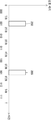
도 5 및 도 6은 복수의 SPAD들을 이용하여 이진 검색에 이용되는 카운팅 증분 값을 결정하는 방식을 설명하기 위한 도면이다.5 and 6 are diagrams for explaining a method of determining a counting increment value used for binary search using a plurality of SPADs.
대괄호 부호 안의 숫자는 서로 다른 SPAD를 구별하기 위한 것으로 도 5 및 도 6을 참조하면 총 8 개의 SPAD들이 이용된다. 8 개의 SPAD들은 동일한 픽셀에 대응할 수 있으며, 동일한 대상체의 거리를 측정하기 위해 이용될 수 있다.Numbers in square brackets are used to distinguish different SPADs. Referring to FIGS. 5 and 6, a total of 8 SPADs are used. Eight SPADs may correspond to the same pixel and may be used to measure the distance of the same object.
이론적으로 SPAD 반응 이벤트(동그라미로 표시)는 대상체에서 반사된 빛 뿐 아니라 태양광에 의해서도 생성될 수 있다. 태양광은 세기가 급격하게 변화하지 않고 모든 SPAD에 동일하게 입사되므로 SPAD마다 반응하는 이벤트의 횟수는 동일하나 반응하는 시간이 수십 ns 이내로 매우 짧기 때문에 모든 SPAD가 동시에 반응하지 않을 확률이 높다. 이와 달리 대상체에서 반사되어 돌아온 빛에 의해 생기는 SPAD 반응 이벤트는 모든 SPAD가 같은 대상체를 보고 있기 때문에 같은 시간에 반응할 확률이 높다. 따라서 픽셀 내부 SPAD 반응 이벤트 개수를 고려하여 태양광에 의한 영향을 줄일 수 있다. 센서 내부의 열에 의한 이벤트나 기타 노이즈에 의한 영향도 태양광과 마찬가지로 간주할 수 있으므로 유사하게 영향을 줄일 수 있다.Theoretically, an SPAD response event (indicated by a circle) may be generated by sunlight as well as light reflected from an object. Since sunlight does not change rapidly in intensity and is incident on all SPADs equally, the number of events that respond to each SPAD is the same, but since the reaction time is very short within tens of ns, all SPADs are highly unlikely to react simultaneously. On the other hand, SPAD reaction events caused by light reflected from an object return are highly likely to react at the same time because all SPADs are looking at the same object. Therefore, it is possible to reduce the influence of sunlight by considering the number of SPAD reaction events inside the pixel. The effects of heat events or other noise inside the sensor can be regarded as in the case of sunlight, so the influence can be reduced similarly.
도 5 및 도 6의 하단의 그래프에서 가로축은 TOF가 속한 시간 축을 나타내며, 세로는 카운팅의 증분을 나타낼 수 있다.In the graphs at the bottom of FIGS. 5 and 6, the horizontal axis represents the time axis to which the TOF belongs, and the vertical axis represents the increment of counting.
도 5 및 도 6에서 공통적으로 단일 SPAD에서만 광자가 감지된 경우 이를 태양광 성분 혹은 노이즈 성분이라 간주하여 카운팅 증분은 0으로 결정될 수 있다. 즉, 수광 이벤트가 발생하지 않은 것으로 간주될 수 있다. 예를 들어 410에서 SPAD[4]에서 광자가 감지되었으나 다른 모든 SPAD들에서 광자가 감지되지 않아 수광 이벤트가 발생하지 않은 것으로 간주되고 카운팅 증분은 0으로 결정될 수 있다. 한편 시점(420)에서 SPAD[0]에서 광자가 감지되었으나, 이는 4 개의 SPAD들에서 광자가 감지된 시점(430)과 시간 지연이 발생한 것으로서 다른 시간에 광자 감지 시점(430)과 구별된다.In FIG. 5 and FIG. 6, when a photon is detected only in a single SPAD, the counting increment may be determined as 0 by considering it as a solar component or a noise component. That is, it may be considered that the light reception event has not occurred. For example, the photon is detected in SPAD[4] at 410, but the photon is not detected in all other SPADs, so that no light receiving event is considered and the counting increment may be determined to be 0. On the other hand, the photon was detected at SPAD[0] at
광자 감지 시점(430)에서 4 개의 SPAD들에서 광자가 감지되었으므로 개수에 비례하게 카운팅 증분이 3으로 결정된다. 즉 1 개의 SPAD에서만 광자가 감지된 경우 노이즈로 간주되므로, 광자를 감지한 SPAD의 개수에 1을 뺀 값이 카운팅 증분으로 결정된다. 태양광의 세기에 따라 수광 이벤트의 발생 횟수를 2나 3으로 증가시켜서 그 이후의 이벤트 횟수만 고려할 수 있다.Since the photons are detected in the four SPADs at the
이와 달린 도 6에서는 동시적인 광자 감지에 더 큰 가중치를 주기 위하여, 기하급수적(exponential)으로 카운팅 증분이 결정된다. 예를 들어, 광자 감지 시점(530)은 도 5에서 광자 감지 시점(430)에 동일하게 대응되나, 3이 아닌 2의 3승 즉 8이 카운팅 증분으로 결정될 수 있다. 이 외에도 다양한 방식으로 카운팅 증분이 결정될 수 있다. In FIG. 6, the counting increment is determined exponentially to give a greater weight to simultaneous photon sensing. For example, the
도 7은 일 실시 예에 따른 거리 측정 장치에 의해 수행되는 거리 측정 방법의 흐름도를 도시한 도면이다.7 is a flowchart illustrating a distance measurement method performed by a distance measurement device according to an embodiment.
도 7에 방법은 도 1의 거리 측정 장치(100)에 의해 수행될 수 있다.The method illustrated in FIG. 7 may be performed by the
단계 710에서, 장치(100)는 미리 결정된 조사 주기로, 대상체에게 광 신호를 조사할 수 있다. In
단계 720에서, 장치(100)는 임계 에너지 이상의 광 신호가 수신되는 수광 이벤트 감지할 수 있다. 예를 들어, 장치(100)는 각각의 픽셀에 할당된 복수의 SPAD들 중 일정 개수 이상의 SPAD들에서 동일한 TOF에 대응하는 광자가 감지되는 경우 수광 이벤트가 발생하였다고 결정할 수 있다.In
단계 730에서, 장치(100)는 수광 이벤트가 감지됨에 따라, 상기 광 신호가 조사된 시점으로부터 상기 광 신호가 수신된 시점 간의 차이인 수광 시간을 결정할 수 있다.In
단계 740에서, 장치(100)는 관심 시간 영역(time range)내의 제 1 기준 시간 이전에 발생한 수광 이벤트의 횟수와 상기 제 1 기준 시간 이후에 발생한 수광 이벤트 횟수의 차이를 결정할 수 있다. 제 1 기준 시간의 관심 시간 영역의 중간 시점일 수 있다.In
단계 750에서, 상기 결정된 횟수의 차이에 기초하여, 상기 광원으로부터 조사된 광 신호가 상기 대상체로부터 반사되어 상기 수광부에 의해 감지되기까지 소요된 비행시간(Time of flight: ToF)을 결정할 수 있다.In
본 실시예들은 컴퓨터에 의해 실행되는 프로그램 모듈과 같은 컴퓨터에 의해 실행 가능한 명령어를 포함하는 기록 매체의 형태로도 구현될 수 있다. 컴퓨터 판독 가능 매체는 컴퓨터에 의해 액세스될 수 있는 임의의 가용 매체일 수 있고, 휘발성 및 비휘발성 매체, 분리형 및 비분리형 매체를 모두 포함한다. 컴퓨터 저장 매체는 컴퓨터 판독가능 명령어, 데이터 구조, 프로그램 모듈 또는 기타 데이터와 같은 정보의 저장을 위한 임의의 방법 또는 기술로 구현된 휘발성 및 비휘발성, 분리형 및 비분리형 매체를 모두 포함한다. The embodiments can also be implemented in the form of a recording medium including instructions executable by a computer, such as program modules, being executed by a computer. Computer readable media can be any available media that can be accessed by a computer, and includes both volatile and nonvolatile media, removable and non-removable media. Computer storage media includes both volatile and nonvolatile, removable and non-removable media implemented in any method or technology for storage of information such as computer readable instructions, data structures, program modules or other data.
본 실시예의 범위는 상기 상세한 설명보다는 후술하는 특허청구범위에 의하여 나타내어지며, 특허청구범위의 의미 및 범위 그리고 그 균등 개념으로부터 도출되는 모든 변경 또는 변형된 형태가 포함되는 것으로 해석되어야 한다.The scope of the present embodiment is indicated by the claims, which will be described later, rather than by the detailed description, and should be interpreted to include all modified or modified forms derived from the meaning and scope of the claims and their equivalent concepts.
Claims (9)
광 신호를 수신하는 적어도 하나의 수광부;
상기 수광부에 의해 임계 에너지 이상의 광 신호가 수신되는 수광 이벤트가 감지됨에 따라, 상기 광원으로부터 광 신호가 조사된 시점으로부터 상기 광 신호가 수신된 시점간의 차이인 수광 시간을 결정하는 수광 시간 결정부;
관심 시간 영역(time range)내의 기준 시간 이전에 발생한 수광 이벤트의 횟수와 상기 기준 시간 이후에 발생한 수광 이벤트 횟수의 차이를 카운팅하는 카운터; 및
프로세서를 포함하고,
상기 프로세서는, 상기 카운터의 카운팅 값에 기초하여, 상기 광원으로부터 조사된 광 신호가 상기 대상체로부터 반사되어 상기 수광부에 의해 감지되기까지 소요된 비행시간(Time of flight: ToF)을 결정하는, 거리 측정 장치.A light source irradiating an optical signal to the object at a predetermined irradiation cycle;
At least one light receiving unit that receives an optical signal;
A light reception time determination unit configured to determine a light reception time that is a difference between a time at which the light signal is received from a time when the light signal is irradiated from the light source, as a light reception event in which a light signal having a threshold energy or more is received is detected by the light reception unit;
A counter for counting the difference between the number of light reception events occurring before the reference time in the time range of interest and the number of light reception events occurring after the reference time; And
Including a processor,
The processor, based on the counting value of the counter, determines a flight time (Time of flight: ToF) taken before the light signal emitted from the light source is reflected from the object and sensed by the light receiving unit Device.
상기 프로세서는,
상기 관심 시간 영역 내의 제 1 기준 시간을 결정하고,
수광 이벤트가 감지됨에 따라, 상기 감지된 수광 이벤트에 대응하는 수광 시간이 상기 제 1 기준 시간 이전인 경우, 상기 카운터에게 업 카운팅 제어 신호를 전송하고,
상기 제 1 기준 시간 이후인 경우, 상기 카운터에게 다운 카운팅 제어 신호를 전송하는, 거리 측정 장치.According to claim 1,
The processor,
Determine a first reference time in the time-of-interest region,
As the light reception event is detected, when the light reception time corresponding to the detected light reception event is before the first reference time, an up counting control signal is transmitted to the counter,
When it is after the first reference time, the distance measuring device transmits a down counting control signal to the counter.
상기 프로세서는,
상기 카운터의 카운팅 값에 기초하여, 상기 비행시간이 상기 제 1 기준 시간보다 큰지 여부를 나타내는 제 1 싱글 비트 값을 획득하고,
상기 획득된 제 1 싱글 비트 값을 상기 비행시간을 나타내는 멀티 비트 데이터의 최상위 비트 값으로 결정하는, 거리 측정 장치.According to claim 1,
The processor,
Based on the counting value of the counter, obtain a first single bit value indicating whether the flight time is greater than the first reference time,
And determining the obtained first single bit value as the most significant bit value of multi-bit data representing the flight time.
상기 프로세서는,
상기 제 1 싱글 비트 값에 기초하여, 상기 관심 시간 영역 중 상기 제 1 기준 시간 이후에 해당하는 서브 영역 및 상기 제 1 기준 시간 이전에 해당하는 작은 서브 영역 중 어느 하나의 서브 영역을 결정하는, 거리 측정 장치. The method of claim 3,
The processor,
Based on the first single bit value, a distance for determining one of the sub-regions corresponding to the first reference time and the smaller sub-regions corresponding to the first reference time of the interest time region. Measuring device.
상기 프로세서는,
상기 결정된 서브 영역 내의 제 2 기준 시간을 결정하고,
수광 이벤트가 감지됨에 따라, 상기 감지된 수광 이벤트에 대응하여 결정된 수광 시간이 상기 제 2 기준 시간 이전인 경우, 상기 카운터에게 업 카운팅 제어 신호를 전송하고,
상기 제 2 기준 시간 이후인 경우, 상기 카운터에게 다운 카운팅 제어 신호를 전송하는, 거리 측정 장치.The method of claim 4,
The processor,
Determine a second reference time in the determined sub-region,
As the light reception event is detected, when the light reception time determined in response to the detected light reception event is before the second reference time, an up counting control signal is transmitted to the counter,
When it is after the second reference time, the distance measuring device transmits a down counting control signal to the counter.
상기 프로세서는,
상기 카운터의 카운팅 값에 기초하여, 상기 비행시간이 상기 제 1 기준 시간보다 큰지 여부를 나타내는 제 2 싱글 비트 값을 획득하고,
상기 획득된 제 2 싱글 비트 값을 상기 비행시간을 나타내는 멀티 비트 데이터의 2 번째 상위 비트 값으로 결정하는, 거리 측정 장치.The method of claim 5,
The processor,
Based on the counting value of the counter, obtain a second single bit value indicating whether the flight time is greater than the first reference time,
And determining the acquired second single bit value as a second upper bit value of multi-bit data indicating the flight time.
상기 수광부는 단일 광자 아발란체 소자(Single Photon Avalanche Diode: SPAD)를 포함하는, 거리 측정 장치. According to claim 1,
The light receiving unit includes a single photon Avalanche Diode (SPAD), a distance measuring device.
상기 수광부는, 복수의 단일 광자 검출 소자들을 포함하고,
상기 복수의 단일 광장 검출 소자들 중 미리 결정된 개수 이상의 단일 광자 검출 소자들에 의해 동일한 수광 시간에 광 신호가 수신된 경우, 상기 프로세서는 상기 수광 이벤트가 발생하였다고 결정하는, 거리 측정 장치.The method of claim 7,
The light receiving unit includes a plurality of single photon detection elements,
When an optical signal is received at the same light receiving time by a single photon detection element having a predetermined number or more among the plurality of single square detection elements, the processor determines that the light reception event has occurred.
미리 결정된 조사 주기로, 대상체에게 광 신호를 조사하는 단계;
임계 에너지 이상의 광 신호가 수신되는 수광 이벤트 감지하는 단계;
수광 이벤트가 감지됨에 따라, 상기 광 신호가 조사된 시점으로부터 상기 광 신호가 수신된 시점간의 차이인 수광 시간을 결정하는 단계;
관심 시간 영역(time range)내의 제 1 기준 시간 이전에 발생한 수광 이벤트의 횟수와 상기 제 1 기준 시간 이후에 발생한 수광 이벤트 횟수의 차이를 결정하는 단계;
상기 결정된 횟수의 차이에 기초하여, 상기 광원으로부터 조사된 광 신호가 상기 대상체로부터 반사되어 상기 수광부에 의해 감지되기까지 소요된 비행시간(Time of flight: ToF)을 결정하는 단계를 포함하는 방법.In the distance measuring method performed by the distance measuring device,
Irradiating an optical signal to the object at a predetermined irradiation cycle;
Detecting a light reception event in which an optical signal having a threshold energy or higher is received;
Determining a light reception time, which is a difference between a time point when the light signal is received, from a time point when the light signal is irradiated, as the light reception event is detected;
Determining a difference between the number of light reception events occurring before the first reference time in the time range of interest and the number of light reception events occurring after the first reference time;
And determining a time of flight (ToF) taken before the light signal irradiated from the light source is reflected from the object and sensed by the light receiving unit based on the difference in the determined number of times.
Priority Applications (1)
| Application Number | Priority Date | Filing Date | Title |
|---|---|---|---|
| KR1020190000868A KR102198941B1 (en) | 2019-01-03 | 2019-01-03 | Apparatus and Method for measuring distance using SPAD(Single Photon Avalanche Diode) using TOF(Time of Flight) |
Applications Claiming Priority (1)
| Application Number | Priority Date | Filing Date | Title |
|---|---|---|---|
| KR1020190000868A KR102198941B1 (en) | 2019-01-03 | 2019-01-03 | Apparatus and Method for measuring distance using SPAD(Single Photon Avalanche Diode) using TOF(Time of Flight) |
Publications (2)
| Publication Number | Publication Date |
|---|---|
| KR20200084699A true KR20200084699A (en) | 2020-07-13 |
| KR102198941B1 KR102198941B1 (en) | 2021-01-05 |
Family
ID=71570603
Family Applications (1)
| Application Number | Title | Priority Date | Filing Date |
|---|---|---|---|
| KR1020190000868A KR102198941B1 (en) | 2019-01-03 | 2019-01-03 | Apparatus and Method for measuring distance using SPAD(Single Photon Avalanche Diode) using TOF(Time of Flight) |
Country Status (1)
| Country | Link |
|---|---|
| KR (1) | KR102198941B1 (en) |
Cited By (1)
| Publication number | Priority date | Publication date | Assignee | Title |
|---|---|---|---|---|
| CN112147626A (en) * | 2020-09-14 | 2020-12-29 | Oppo广东移动通信有限公司 | Electronic device, control method of electronic device, and computer-readable storage medium |
Families Citing this family (1)
| Publication number | Priority date | Publication date | Assignee | Title |
|---|---|---|---|---|
| WO2023038417A1 (en) * | 2021-09-08 | 2023-03-16 | 주식회사 솔리드뷰 | Flash lidar sensor using zoom histogramming tdc |
Citations (4)
| Publication number | Priority date | Publication date | Assignee | Title |
|---|---|---|---|---|
| KR100310791B1 (en) * | 1999-03-19 | 2001-10-17 | 장경영 | Apparatus for measuring distance by using laser |
| JP4367099B2 (en) * | 2003-11-18 | 2009-11-18 | 横河電機株式会社 | Distance measuring device |
| JP2017003461A (en) * | 2015-06-11 | 2017-01-05 | 東芝テック株式会社 | Distance measurement device |
| KR20180075091A (en) * | 2016-12-26 | 2018-07-04 | 연세대학교 산학협력단 | Apparatus and method for determining optical signal reflected from target in depth sensor |
-
2019
- 2019-01-03 KR KR1020190000868A patent/KR102198941B1/en active IP Right Grant
Patent Citations (4)
| Publication number | Priority date | Publication date | Assignee | Title |
|---|---|---|---|---|
| KR100310791B1 (en) * | 1999-03-19 | 2001-10-17 | 장경영 | Apparatus for measuring distance by using laser |
| JP4367099B2 (en) * | 2003-11-18 | 2009-11-18 | 横河電機株式会社 | Distance measuring device |
| JP2017003461A (en) * | 2015-06-11 | 2017-01-05 | 東芝テック株式会社 | Distance measurement device |
| KR20180075091A (en) * | 2016-12-26 | 2018-07-04 | 연세대학교 산학협력단 | Apparatus and method for determining optical signal reflected from target in depth sensor |
Cited By (1)
| Publication number | Priority date | Publication date | Assignee | Title |
|---|---|---|---|---|
| CN112147626A (en) * | 2020-09-14 | 2020-12-29 | Oppo广东移动通信有限公司 | Electronic device, control method of electronic device, and computer-readable storage medium |
Also Published As
| Publication number | Publication date |
|---|---|
| KR102198941B1 (en) | 2021-01-05 |
Similar Documents
| Publication | Publication Date | Title |
|---|---|---|
| CN110073244B (en) | Histogram readout method and circuit for determining the time of flight of photons | |
| US20240028667A1 (en) | Method and apparatus for processing a histogram output from a detector sensor | |
| CN110596721B (en) | Flight time distance measuring system and method of double-shared TDC circuit | |
| US10291895B2 (en) | Time of flight photosensor | |
| JP5206297B2 (en) | Optical distance measuring apparatus and method | |
| US8610043B2 (en) | Proximity sensor having an array of single photon avalanche diodes and circuitry for switching off illumination source and associated method, computer readable medium and firmware | |
| US11644551B2 (en) | Lidar systems with improved time-to-digital conversion circuitry | |
| EP2446301B1 (en) | Pulsed light optical rangefinder | |
| CN110596722A (en) | System and method for measuring flight time distance with adjustable histogram | |
| JP6665873B2 (en) | Photo detector | |
| JP6709335B2 (en) | Optical sensor, electronic device, arithmetic unit, and method for measuring distance between optical sensor and detection target | |
| JPWO2014207992A1 (en) | Ranging imaging apparatus, ranging method thereof, solid-state imaging device | |
| US20220221562A1 (en) | Methods and systems for spad optimizaiton | |
| KR102198941B1 (en) | Apparatus and Method for measuring distance using SPAD(Single Photon Avalanche Diode) using TOF(Time of Flight) | |
| CN111580074B (en) | Time precision calibration method and device and electronic equipment | |
| US20220099814A1 (en) | Power-efficient direct time of flight lidar | |
| US9115990B2 (en) | Geospatial and image data collection system including image sensor for capturing 3D geospatial data and 2D image data and related methods | |
| JP6735515B2 (en) | Solid-state imaging device | |
| CN112346076A (en) | Control method of electronic device, and computer-readable storage medium | |
| US20200408910A1 (en) | Distance measuring method and distance measuring device | |
| WO2020196257A1 (en) | Distance measurement method, distance measurement device, and program | |
| CN109729289A (en) | Optical sensor and detection method | |
| US20230019246A1 (en) | Time-of-flight imaging circuitry, time-of-flight imaging system, and time-of-flight imaging method | |
| CN114488176A (en) | 3D image sensor ranging system and method for ranging by using same | |
| RU2521203C1 (en) | Method of detecting objects, measuring velocity, range and angular coordinates and apparatus for realising said method |
Legal Events
| Date | Code | Title | Description |
|---|---|---|---|
| E902 | Notification of reason for refusal | ||
| E701 | Decision to grant or registration of patent right | ||
| GRNT | Written decision to grant |