KR20200083888A - Front suspension fork for bicycle - Google Patents
Front suspension fork for bicycle Download PDFInfo
- Publication number
- KR20200083888A KR20200083888A KR1020190000028A KR20190000028A KR20200083888A KR 20200083888 A KR20200083888 A KR 20200083888A KR 1020190000028 A KR1020190000028 A KR 1020190000028A KR 20190000028 A KR20190000028 A KR 20190000028A KR 20200083888 A KR20200083888 A KR 20200083888A
- Authority
- KR
- South Korea
- Prior art keywords
- damper
- fork
- oil
- air
- piston
- Prior art date
Links
Images


Classifications
-
- B—PERFORMING OPERATIONS; TRANSPORTING
- B62—LAND VEHICLES FOR TRAVELLING OTHERWISE THAN ON RAILS
- B62K—CYCLES; CYCLE FRAMES; CYCLE STEERING DEVICES; RIDER-OPERATED TERMINAL CONTROLS SPECIALLY ADAPTED FOR CYCLES; CYCLE AXLE SUSPENSIONS; CYCLE SIDE-CARS, FORECARS, OR THE LIKE
- B62K25/00—Axle suspensions
- B62K25/04—Axle suspensions for mounting axles resiliently on cycle frame or fork
- B62K25/06—Axle suspensions for mounting axles resiliently on cycle frame or fork with telescopic fork, e.g. including auxiliary rocking arms
- B62K25/08—Axle suspensions for mounting axles resiliently on cycle frame or fork with telescopic fork, e.g. including auxiliary rocking arms for front wheel
-
- B—PERFORMING OPERATIONS; TRANSPORTING
- B62—LAND VEHICLES FOR TRAVELLING OTHERWISE THAN ON RAILS
- B62K—CYCLES; CYCLE FRAMES; CYCLE STEERING DEVICES; RIDER-OPERATED TERMINAL CONTROLS SPECIALLY ADAPTED FOR CYCLES; CYCLE AXLE SUSPENSIONS; CYCLE SIDE-CARS, FORECARS, OR THE LIKE
- B62K21/00—Steering devices
- B62K21/02—Front wheel forks or equivalent, e.g. single tine
-
- B—PERFORMING OPERATIONS; TRANSPORTING
- B62—LAND VEHICLES FOR TRAVELLING OTHERWISE THAN ON RAILS
- B62K—CYCLES; CYCLE FRAMES; CYCLE STEERING DEVICES; RIDER-OPERATED TERMINAL CONTROLS SPECIALLY ADAPTED FOR CYCLES; CYCLE AXLE SUSPENSIONS; CYCLE SIDE-CARS, FORECARS, OR THE LIKE
- B62K21/00—Steering devices
- B62K21/06—Bearings specially adapted for steering heads
-
- B—PERFORMING OPERATIONS; TRANSPORTING
- B62—LAND VEHICLES FOR TRAVELLING OTHERWISE THAN ON RAILS
- B62K—CYCLES; CYCLE FRAMES; CYCLE STEERING DEVICES; RIDER-OPERATED TERMINAL CONTROLS SPECIALLY ADAPTED FOR CYCLES; CYCLE AXLE SUSPENSIONS; CYCLE SIDE-CARS, FORECARS, OR THE LIKE
- B62K21/00—Steering devices
- B62K21/18—Connections between forks and handlebars or handlebar stems
-
- F—MECHANICAL ENGINEERING; LIGHTING; HEATING; WEAPONS; BLASTING
- F16—ENGINEERING ELEMENTS AND UNITS; GENERAL MEASURES FOR PRODUCING AND MAINTAINING EFFECTIVE FUNCTIONING OF MACHINES OR INSTALLATIONS; THERMAL INSULATION IN GENERAL
- F16F—SPRINGS; SHOCK-ABSORBERS; MEANS FOR DAMPING VIBRATION
- F16F9/00—Springs, vibration-dampers, shock-absorbers, or similarly-constructed movement-dampers using a fluid or the equivalent as damping medium
- F16F9/06—Springs, vibration-dampers, shock-absorbers, or similarly-constructed movement-dampers using a fluid or the equivalent as damping medium using both gas and liquid
-
- F—MECHANICAL ENGINEERING; LIGHTING; HEATING; WEAPONS; BLASTING
- F16—ENGINEERING ELEMENTS AND UNITS; GENERAL MEASURES FOR PRODUCING AND MAINTAINING EFFECTIVE FUNCTIONING OF MACHINES OR INSTALLATIONS; THERMAL INSULATION IN GENERAL
- F16F—SPRINGS; SHOCK-ABSORBERS; MEANS FOR DAMPING VIBRATION
- F16F9/00—Springs, vibration-dampers, shock-absorbers, or similarly-constructed movement-dampers using a fluid or the equivalent as damping medium
- F16F9/32—Details
- F16F9/44—Means on or in the damper for manual or non-automatic adjustment; such means combined with temperature correction
- F16F9/443—Means on or in the damper for manual or non-automatic adjustment; such means combined with temperature correction manually adjusted while the damper is fully retracted or extended in a non-operational mode by rotating mechanical means that have engaged between the piston and one end of the cylinder
-
- B—PERFORMING OPERATIONS; TRANSPORTING
- B62—LAND VEHICLES FOR TRAVELLING OTHERWISE THAN ON RAILS
- B62K—CYCLES; CYCLE FRAMES; CYCLE STEERING DEVICES; RIDER-OPERATED TERMINAL CONTROLS SPECIALLY ADAPTED FOR CYCLES; CYCLE AXLE SUSPENSIONS; CYCLE SIDE-CARS, FORECARS, OR THE LIKE
- B62K2201/00—Springs used in cycle frames or parts thereof
- B62K2201/08—Fluid springs
Landscapes
- Engineering & Computer Science (AREA)
- Mechanical Engineering (AREA)
- General Engineering & Computer Science (AREA)
- Fluid-Damping Devices (AREA)
- Axle Suspensions And Sidecars For Cycles (AREA)
Abstract
Description
본 발명은 자전거 서스펜션 포크에 관한 것으로, 상세하게는 헤드튜브 내측에 댐퍼조절기가 제공되는 자전거 프런트 서스펜션 포크에 관한 것이다.The present invention relates to a bicycle suspension fork, and more particularly, to a bicycle front suspension fork provided with a damper adjuster inside the head tube.
일반적으로 자전거 프런트 서스펜션 포크는 자전거 전륜 휠의 양측에 마주보게 구성되어 자전거 전륜 휠 외부충격 감쇠 및 충격완충을 유도하여 자전거의 승차감 개선과 구동 휠의 접지력을 확보하게 된다.In general, the front suspension fork of the bicycle is configured to face both sides of the front wheel of the bicycle to induce external shock damping and shock absorption of the front wheel of the bicycle, thereby improving the riding comfort of the bicycle and securing the traction of the driving wheel.
통상적으로 종래의 자전거 서스펜션 포크는 첨부도면 제16도에 예시되는 바와 같이 서스펜션 포크(1)의 스티어링 튜브(10)에서 분기되는 크라운(20)의 양단부에 고정되게 구성된 채, 자전거 전륜 휠 양측에 배치되는데 있어서, 일측의 압축서스펜션 포크(60)는 외부 충격에 따라 코일 스프링(64) 또는 밀폐된 에어챔버(65)의 압축공기 탄성력을 이용한 에어 스프링("압축공기의 팽창력을 이용한 탄발력" 이하 에어 스프링이라 칭함)의 탄발력을 이용하여 압축 또는 신장되는 압축서스펜션 포크(60)가 구성되며, 또한 타측의 댐퍼서스펜션 포크(50)는 외부충격에 따른 압축 댐퍼작용 및 리바운드 댐퍼작용을 제어 조절하는 댐퍼서스펜션 포크(50)가 구성된채, 상기 각각의 압축서스펜션 포크(60)와 댐퍼서스펜션 포크(50)는 아치연결부재(40)로 고정되게 연결된 채, 한 쌍의 서스펜션 포크(1)를 구성하게 된다.Typically, a conventional bicycle suspension fork is configured to be fixed to both ends of the
이렇게 구성된 서스펜션 포크(1)는 압축서스펜션 포크(60)와 댐퍼서스펜션 포크(50)가 각각 다른 역할기능(예컨데, 압축서스펜션 포크는; 로면의 충격에 따라 압축 또는 신장작용에 신속히 대응되며, 상기 댐퍼서스펜션 포크는; 상기 압축서스펜션의 압축 또는 신장력을 제어하는 상반된 작용을 하여 로면의 충격을 감쇠시킴)으로 상반되는 작용을 하게 되므로, 상기 압축서스펜션 포크(60)와 상기 댐퍼서스펜션 포크(50)를 한 쌍으로 연결하는 상기 아치연결부재(40)는 상기 두 개의 서스펜션 포크(50),(60) 사이에 언발란스가 없도록 견고하게 구성됨과 아울러, 상반되는 다른 기능역할에 따라 상기 두 개의 서스펜션 포크(50),(60)는 좀 더 튼튼하게 구성되어 무게가 증가되는 문제점이 있었다.The thus configured
또한 상기 압축서스펜션 포크(60)에 사용되는 코일 스프링(64)은 압축 및 신장되는 길이변화가 한정되어 서스펜션 포크(1)의 가변량이 제한됨과 아울러 코일 스프링(64)의 무게가 증가되는 문제점이 있어, 이를 해소하고자 최근에는 상기 압축서스펜션 포크(60)의 내통 실린더(62)에 피스톤(63)을 장착한채, 상기 피스톤(63) 상측의 에어챔버(65)에 공기압을 이용한 에어 스프링이 함께 도입되어 상기 코일 스프링(64)의 문제점을 보완하였으나, 상기 에어 스프링은 서스펜션 포크의 기능에 있어서, 외부충격에 대항하는 압축 또는 팽창작용에 국한된채, 댐퍼작용의 기능을 수행하지 못하는 기능상의 제약점이 내포되어 있었다.In addition, the
그리고 무엇보다 상기 압축서스펜션 포크로 활용되는 에어 스프링 방식은 하나의 독립적인 실린더에 한정되어 압축유체의 팽창과 압축작용이 함께 연출되게 되므로 압축서스펜션 실린더의 한정된 밀폐공간 상태에서 압축비가 크게 형성되게 된다. 이로써 압축유체의 압력이 높을 경우 서스펜션 포크의 댐퍼성능이 저하되며, 또한 압축유체의 압력이 낮을 경우 서스펜션 포크의 외부충격에 따른 압축 팽창성이 저하되는 문제가 있어 이를 개선 하고자 할 경우 압축서스펜션 포크의 크기를 크게 구성하게 되면, 자전거 프레임의 무게가 증가되게 된다.And above all, the air spring method utilized as the compression suspension fork is limited to one independent cylinder, so that the expansion and compression of the compressed fluid are performed together, so that the compression ratio is largely formed in the confined space of the compression suspension cylinder. As a result, when the pressure of the compressed fluid is high, the damper performance of the suspension fork decreases, and when the pressure of the compressed fluid is low, there is a problem that the compressive expandability due to the external shock of the suspension fork decreases. When configured largely, the weight of the bicycle frame is increased.
여기서 미 설명부호 66은 에어주입구 이며, 또한 미 설명부호 51,61은 상기 서스펜션 포크(1)의 외통 실린더이고, 미 설명부호 55는 오일챔버이다.Here,
상기 댐퍼서스펜션 포크(50)는; 댐퍼서스펜션 포크(50) 내통 실린더(52)에 오일을 매개체로하는 오일의 유체흐름 제어를 연출하여 서스펜션 포크(1)의 외부충격에 따라 압축 댐퍼작용을 수행하는 압축 댐퍼수단(53) 및 리바운드 댐퍼작용을 수행하는 리바운드 댐퍼수단(54)의 두 가지 제어조절 기능이 각각 제공되는데 있어서, 상기 압축 댐퍼수단(53)은; 도로 로면이 포장되어 로면이 고른 주행길 또는 언덕길 상승 주행(업 휠)시 페달을 밝는 에너지 손실을 저감하기 위히여 주로 사용하는 기능으로써, 도로 로면이 포장되어 빠른 주행이 필요 하거나, 언덕길 주행시에는 압축 댐퍼수단(53)을 차단(락 아웃)상태로 주행하는 것이 바람직하며, 이러한 상기 압축 댐퍼수단(53) 제어조절 기능의 댐퍼조절레버(30)은 댐퍼서스펜션 포크(50) 상부에 제공되어 자전거 주행중 임의로 압축 댐퍼작용을 조절할 수 있게 된다.The damper suspension fork (50); Damper suspension fork (50) Compressed damper means (53) and rebound damper to perform a compression damper function according to the external shock of the suspension fork (1) by directing the fluid flow control of the oil as a medium to the inner cylinder (52) Two control adjustment functions of the rebound damper means 54 performing the action are provided, respectively, wherein the compression damper means 53 includes; This is a function mainly used to reduce the energy loss that brightens the pedal when the road surface is paved and the road surface is even or the hill road is uphill (up wheel). It is preferable to drive the damper means 53 in a blocked (locked out) state, and the
반면에, 상기 리바운드 댐퍼수단(54)은; 도로 로면이 비포장되어 요철부가 있는 주행길의 자전거 주행중 통상적인 외부충격에 따라 댐퍼서스펜션 포크(50)가 압축되었다가 팽창 및 신장되는 리바운드 댐퍼작용을 구현하여 자전거 주행의 외부충격 댐퍼작용 기능을 연출하게 되는 것으로, 리바운드 댐퍼수단(54)의 제어조절은 서스펜션 포크(50) 하부에 제공되는 댐퍼조절체(31)에 의하여 리바운드 댐퍼작용 조절이 구현되므로 자전거 주행중 임의로 리바운드 댐퍼작용의 제어조절이 불가능하는 문제점이 있었다.On the other hand, the rebound damper means 54; The road surface is unpaved, and the
그리고 무엇보다 상기 압축 댐퍼수단(53)과 상기 리바운드 댐퍼수단(54)을 함께 구성하여 연출하는 제어조절수단이 복잡하게 구성되어 댐퍼서스펜션 포크(50)의 구성이 복잡함과 아울러 고장에 따른 수리 및 정비관리가 난이하며, 또한 댐퍼조절 가변길이가 제한되는 문제점이 있으며, 상기 댐퍼조절 가변길이를 확장하고자 할 경우 댐퍼서스펜션 포크의 길이가 크게 확장되어 자전거 경량화를 요구하는 수준에 비하여 무게가 크게 증가되는 문제점이 있다.And above all, the compression damper means 53 and the rebound damper means 54 are composed of a complex control control means to produce the
또 종래의 서스펜션 포크(1)는 외부충격에 따른 리바운드 댐퍼수단(54)에 의하여 댐퍼작용이 연출되는 반면에, 압축 댐퍼수단(53)에는 외부충격에 따른 단순 탄발력의 작용이 연출되어 서스펜션 포크의 세밀한 댐퍼제어 및 높낮이 제어 조절의 구성에 따른 댐퍼제어 효율성이 낮은 문제가 있었다.In addition, in the
따라서, 본 발명은 상기의 여러 문제점을 해소하고자 연출한 것으로,Therefore, the present invention was directed to solve the above problems,
종래의 서스펜션 포크는 압축 서스펜션포크 및 댐퍼 서스펜션포크로 각각 구성된 채, 상기 두 개의 서스펜션 포크가 아치연결부재에 의하여 한 쌍으로 구성되는 방식인바' 그 구성이 복잡하고 무게가 증가되는 문제를 해소함과 아울러 자전거의 핸들에서 간단하게 구성되는 조절레바를 이용하여 자전거 프런트 서스펜션 포크의 댐퍼조절기 댐퍼제어가 용이하게 연출되고, 또한 자전거 프런트 포크에 압축유체가 저장되어 프런트 포크의 강성이 증가되며, 또 댐퍼조절기는 그 구조가 간단하게 구성된채, 댐퍼제어 수단이 압축유체 및 오일유체로 함께 연출되어 댐퍼제어 성능이 개선됨과 아울러 높낮이제어가 연출되는 효율성이 우수한 자전거 프런트 서스펜션 포크를 제공하는데 그 목적이 있다.The conventional suspension fork is composed of a compression suspension fork and a damper suspension fork, respectively, and the two suspension forks are configured in a pair by an arch connecting member. The structure is complicated and the weight is increased. The damper controller of the bicycle front suspension fork is easily created by using the adjustment lever that is simply configured on the handle of the bicycle, and the compressed fluid is stored in the bicycle front fork to increase the rigidity of the front fork. Its purpose is to provide a bicycle front suspension fork with high efficiency in which the damper control performance is improved and the height control is produced as the damper control means is directed together with a compressed fluid and an oil fluid while the structure is simple.
자전거 프레임을 구성하는 헤드튜브 내부 상측으로 축수부재가 구성된채, 상기 축수부재 하측으로 댐퍼제어가 연출되는 댐퍼조절기가 제공되는데 있어서,In the head tube constituting the bicycle frame is provided with a damper controller that is configured with a water-reducing member in the upper side, and damper control is directed to the lower side of the water-reducing member,
상기 댐퍼조절기는 헤드튜브 내ㆍ외부로 출입되는 댐퍼실린더 및, 상기 댐퍼실린더 내ㆍ외부로 출입되는 시프트로드가 구성되어 상기 시프트로드 상측에는; 고정체가 포함되는 로드헤드부재가 구성된채, 상기 고정체가 축수부재 상측으로 관통되어 고정수단으로 체결되며, 또한 상기 댐퍼실린더 하측에는 프런트 포크가 결합되어 상기 프런트 포크를 포함하는 상기 댐퍼실린더 및 시프트로드 내측에 압축유체가 저장되는 것과; 상기 댐퍼실린더에 구성되는 커버부재에 키홈이 형성되며, 또한 상기 로드헤드부재에는 커버부재의 키홈으로 출입되는 슬라이드 키가 고정되게 결합되어 상기 댐퍼실린더와 로드헤드부재가 함께 회동되는 것과; 상기 시프트로드의 하단에 피스톤이 구성되어 댐퍼실린더 내부에 배치된채, 상기 피스톤에는; 댐퍼조절수단이 제공되는 특징으로 상기 헤드튜브 내측에서 댐퍼조절기가 회동됨과 아울러 댐퍼조절 작용이 함께 이루어지는 수단을 제공할 수 있다.The damper regulator comprises a damper cylinder that enters and exits the head tube, and a shift rod that enters and exits the damper cylinder; While the rod head member including the fixed body is configured, the fixed body is penetrated to the upper side of the water-reducing member and fastened by a fixing means, and a front fork is coupled to the lower side of the damper cylinder, and the damper cylinder and shift including the front fork are shifted. A compressed fluid is stored inside the rod; A key groove is formed in the cover member constituting the damper cylinder, and a slide key that enters and exits the key groove of the cover member is fixedly coupled to the load head member so that the damper cylinder and the rod head member are rotated together; A piston is configured at a lower end of the shift rod and disposed inside the damper cylinder, the piston; As a feature in which a damper adjusting means is provided, a damper adjusting device is rotated inside the head tube, and a damper adjusting function can be provided.
상기 댐퍼조절기는; 댐퍼실린더 내측에 댐퍼조절수단 및, 시프트로드가 결합된 피스톤이 배치되어 에어압력실과 오일압력실이 형성되며, 또한 시프트로드 내측에 상기 에어압력실의 압축유체가 저장되는 에어댐퍼실이 형성되고, 또 상기 시프트로드 내측에는 댐퍼조절수단을 제어 조절하는 댐퍼조절부재가 구성된채, 상기 댐퍼조절부재의 내측에는 오일압력실과 제한적으로 연통되는 오일챔버가 형성되며, 또한 상기 프런트 포크에는 자전거 전륜휠을 지지하는 한 쌍의 포크튜브 상단부에 포크헤드부재가 구성되어 상기 포크튜브에는 에어탱크가 형성된채, 상기 댐퍼실린더가 고정되게 결합되어 에어압력실의 압축유체가 에어댐퍼실 및 에어탱크로 출입되는 특징으로 압축유체의 댐퍼작용과 오일유체의 댐퍼조절 작용이 함께 이루어지는 수단을 제공할 수 있다.The damper regulator; A damper adjustment means and a piston coupled with a shift rod are disposed inside the damper cylinder to form an air pressure chamber and an oil pressure chamber, and an air damper chamber is formed inside the shift rod to store the compressed fluid of the air pressure chamber. Inside the shift rod, a damper adjusting member configured to control and adjust the damper adjusting means is formed, and an oil chamber limitedly communicating with an oil pressure chamber is formed inside the damper adjusting member, and the front fork supports a bicycle front wheel. A fork head member is formed at the upper end of a pair of fork tubes, and an air tank is formed on the fork tube, and the damper cylinder is fixedly coupled so that the compressed fluid in the air pressure chamber enters and exits the air damper chamber and the air tank. It is possible to provide a means that the damper action and the damper control action of the oil fluid are made together.
자전거 전륜휠을 지지하는 한 쌍의 포크튜브 상단부에 포크헤드부재가 구성된채, 상기 포크헤드부재에는 에어 주입수단이 제공되어 댐퍼조절기에 압축유체가 주입되는 수단을 제공할 수 있다.While the fork head member is configured at the upper end of the pair of fork tubes supporting the front wheel of the bicycle, the fork head member is provided with an air injection means to provide a means for injecting compressed fluid into the damper regulator.
상기 헤드튜브 상부 내측에는 축수부재가 고정되게 결합된채, 상기 축수부재의 상측과 하측에는 상ㆍ하 베어링이 배치되어 상기 댐퍼조절기가 회동되게 결합되는 수단을 제공할 수 있다.An upper and lower bearings are disposed on the upper and lower sides of the water-reducing member while the water-reducing member is fixedly coupled to the upper inner side of the head tube, thereby providing a means for the damper regulator to be rotated.
상기 시프트로드에 고정되게 결합되는 로드헤드부재 하측으로 직경이 확장되는 베어링지지부가 구성되어 상기 축수부재의 하부베어링과 회동되게 결합된채, 로드헤드부재의 베어링지지부 외곽으로 키홈에 형성된채, 슬라이드 키가 제공되며, 또한 상기 댐퍼실린더의 커버부재 외곽에는 수직으로 개방되는 다 수개의 키홈이 형성된채, 상기 슬라이드 키가 커버부재의 키홈으로 슬라이딩되게 출입되는 특징으로 로드헤드부재의 회전에 따라 댐퍼실린더 및 프런트 포크가 함께 회동되는 수단을 제공할 수 있다.A bearing support is formed that extends in diameter to the lower side of the rod head member that is fixedly coupled to the shift rod, and is coupled to rotate with the lower bearing of the water bearing member, while being formed in the keyway outside the bearing support portion of the rod head member, slide key In addition, a plurality of key grooves are formed vertically open on the outer side of the cover member of the damper cylinder, and the slide key slides into and out of the key groove of the cover member. The front fork can provide a means to rotate together.
상기 프런트 포크는; 상기 포크헤드부재 양측 하부에 튜브결합홀이 형성된채, 상기 포크튜브가 고정되게 결합되어 상기 포크튜브들에 에어탱크가 형성되며, 또한 포크튜브 하단에는 자전거 전륜휠이 결합됨과 아울러 상기 포크튜브 하단부가 밀폐되는 휠고정부재가 고정되게 결합되며, 또 상기 포크헤드부재 상면 중심으로 결합홀이 형성되어 상기 댐퍼실린더가 밀착되게 배치된채, 상기 댐퍼실린더 하측 외주에 구성되는 고정부재가 상기 포크헤드부재 상면에 고정되게 결합되는 특징으로 상기 에어탱크에 압축유체가 저장된채, 상기 댐퍼실린더의 회전에 따라 상기 프런트 포크가 함께 회동되는 수단을 제공할 수 있다.The front fork; While the tube coupling holes are formed on both sides of the fork head member, the fork tube is fixedly coupled to form an air tank on the fork tubes, and at the bottom of the fork tube, a front wheel of a bicycle is coupled and a lower end of the fork tube The fixed wheel fixing member is fixedly coupled, and a coupling hole is formed in the center of the upper surface of the fork head member so that the damper cylinder is disposed in close contact, and the fixing member configured on the lower circumference of the damper cylinder is the upper surface of the fork head member With a feature that is fixedly coupled to the compressed air in the air tank, it is possible to provide a means for rotating the front fork together according to the rotation of the damper cylinder.
상기 헤드튜브의 내측에 상기 축수부재가 착탈식으로 고정되게 결합되어 상기 축수부재의 상부 및 하부에 베어링이 제공될 수 있다.The water-reducing member is fixedly detachably coupled to the inside of the head tube to provide bearings on the upper and lower parts of the water-reducing member.
상기 댐퍼조절기의 에어압력실과 에어댐퍼실이 제한적으로 연통되고, 상기 에어댐퍼실과 에어탱크가 상호 연통되어 압축유체의 댐퍼작용이 연출되는데 있어서, 상기 피스톤에는; 상ㆍ하면이 상호 연통되어 압축유체가 출입되는 배출유로를 포함하여 댐퍼유로 및 유출입로가 형성된채, 상기 피스톤 상면에는 상기 댐퍼조절수단에 구성되는 에어발브체가 배치되어 상기 배출유로를 포함하여 댐퍼유로 및 유출입로가 제한적으로 개폐되며, 또한 상기 배출유로에는 압축유체를 일방향으로 유출시키는 첵크발브부재가 제공되어 상기 댐퍼유로를 통하여 에어댐퍼실에서 에어압력실로 복귀되는 압축유체의 댐퍼작용이 연출되는 수단을 제공할 수 있다.The air pressure chamber and the air damper chamber of the damper regulator are limitedly communicated, and the air damper chamber and the air tank are in communication with each other to produce a damping action of the compressed fluid, wherein the piston includes: The upper and lower surfaces are in communication with each other, and a damper channel and an outlet channel are formed, including an outlet channel through which compressed fluid enters and exits, and an air valve body constituted by the damper control means is disposed on the upper surface of the piston to provide a damper channel including the outlet channel. And a flow path is limitedly opened and closed, and a discharge valve is provided with a shank valve member that discharges compressed fluid in one direction to provide a means for damping the compressed fluid to return to the air pressure chamber from the air damper chamber through the damper flow path. Can provide.
상기 피스톤 하면의 유출입로에는; 나선형의 에어호수가 구성된 일측의 에어연결부재가 고정되게 결합되며, 또한 상기 에어호수의 타측 에어연결부재는 상기 댐퍼실린더의 하부에 구성되는 헤드부재에 고정되게 결합되어 에어호수가 상기 댐퍼실린더의 에어압력실에서 상ㆍ하로 가변되는 나선형으로 배치되는 특징으로 상기 에어댐퍼실과 에어탱크로 압축유체가 출입되는 수단을 제공할 수 있다.On the outflow passage of the lower surface of the piston; The air connection member on one side of the spiral air lake is fixedly coupled, and the other air connection member on the other side of the air lake is fixedly coupled to the head member configured under the damper cylinder so that the air lake is the air pressure chamber of the damper cylinder. It can be provided with a means to enter and exit the compressed fluid into the air damper chamber and the air tank with a characteristic of being arranged in a spiral that is variable up and down.
댐퍼조절기의 상기 오일압력실과 상기 댐퍼조절부재의 내측에 형성되는 오일챔버가 제한적으로 연통되어 오일유체의 댐퍼작용이 연출되는데 있어서, 상기 피스톤 상면 중심부에는 오일댐퍼유로를 포함하여 오일발브챔버 및 발브작동홀이 형성되며, 또한 상기 피스톤에는 오일댐퍼유로에서 오일압력실과 연통되는 오일유출로 및, 오일발브챔버에서 오일압력실과 연통되는 오일유입로가 각각 형성된채, 상기 오일댐퍼유로 하측에 오일주입구가 형성되어 오일커버가 피스톤 하면에 고정되게 체결되는 것과; 피스톤의 상기 오일유입로에는 첵크발브가 장착되며, 또한 상기 오일발브챔버의 내주면으로 나사체결부가 형성된채, 오일발브체가 체결되어 상기 오일댐퍼유로가 제한적으로 개폐되며, 또 피스톤의 발브작동홀에는 댐퍼조절수단에 구성되는 발브작동체가 결합된채, 상기 발브작동체가 오일발브체와 결합되어 댐퍼조절수단의 발브작동체를 회전하게 되면, 오일발브체의 개폐작용이 연출되는 특징으로 댐퍼조절기의 오일유체 댐퍼작용이 제어 조절되는 수단을 제공할 수 있다.The oil pressure chamber of the damper regulator and the oil chamber formed inside the damper adjusting member are in limited communication to produce a damper effect of the oil fluid. In the center of the upper surface of the piston, an oil valve chamber and an oil valve chamber including an oil damper flow path are operated. A hole is formed, and in the oil damper passage, an oil inlet passage communicating with the oil pressure chamber and an oil inlet passage communicating with the oil pressure chamber in the oil valve chamber are respectively formed, and an oil inlet is formed below the oil damper passage. The oil cover is fixedly fastened to the lower surface of the piston; A shank valve is mounted on the oil inlet passage of the piston, and an oil valve body is fastened with a screw fastening portion formed on an inner circumferential surface of the oil valve chamber, and the oil damper flow path is limitedly opened and closed. When the valve actuator configured in the adjusting means is coupled, and the valve actuator is combined with the oil valve body to rotate the valve actuator of the damper adjusting means, the opening and closing action of the oil valve body is produced, so that the oil fluid of the damper regulator is produced. It is possible to provide a means by which the damper action is controlled and controlled.
상기 댐퍼조절수단은; 피스톤 상면에 밀착 슬라이딩되는 원판형상의 평면체로 구성되는 에어발브체가 구성된채, 에어발브체의 하측으로 원통형상의 상기 발브작동체가 구성되며, 또한 에어발브체 상면으로 직경이 작은 원통형상의 결합체가 구성된채, 댐퍼조절부재가 결합되어 댐퍼조절부재를 회전하게 되면, 압축유체의 댐퍼작용이 제어 조절됨과 아울러 오일유체의 댐퍼조절 제어가 이루어지는 수단을 제공할 수 있다.The damper control means; An air valve body composed of a disk-like flat body slidingly in contact with the upper surface of the piston is constructed, and the valve body of the cylindrical body is formed below the air valve body, and a cylindrical body having a small diameter is formed as an upper surface of the air valve body. When the damper adjustment member is coupled to rotate the damper adjustment member, the damper action of the compressed fluid is controlled and regulated, and a damper adjustment control of the oil fluid can be provided.
댐퍼조절부재 상단으로 댐퍼조작부가 결합되어 상기 댐퍼조작부가 상기 축수부재 및 로드헤드부재의 상단으로 돌출된채, 조절레바가 고정되게 결합되는 특징으로 조절레바를 회전하면 압축유체의 댐퍼작용이 제어 조절됨과 아울러 오일유체의 댐퍼조절 제어 작용이 연출되는 수단을 제공할 수 있다.The damper operation part is coupled to the top of the damper adjustment member, and the damper operation part protrudes to the top of the water-reducing member and the rod head member, and the adjustment lever is fixed. In addition, it is possible to provide a means for controlling the damper control of the oil fluid.
댐퍼실린더의 상측 외주면에 커버부재가 고정되게 결합된채, 상기 커버부재의 내측에는 시프트로드가 밀착 슬라이딩되게 출입되는 부싱부재가 고정되게 결합되어 오일패킹 및 오일링이 장착되는 것과; 댐퍼실린더 하부 내측에는 헤드부재가 결합되며, 또한 상기 댐퍼실린더 하측 외주에는; 고정부재가 고정되게 결합되어 상기 프런트 포크와 고정되게 결합되는 수단을 제공할 수 있다.While the cover member is fixedly coupled to the upper outer circumferential surface of the damper cylinder, a bushing member that is shifted in and out of the cover member is fixedly coupled to the inside of the cover member, so that an oil packing and an oil ring are mounted; A head member is coupled to the lower inner side of the damper cylinder, and further on the lower circumference of the damper cylinder; The fixing member is fixedly coupled to provide a means for being fixedly coupled to the front fork.
상기 댐퍼실린더를 구성하는 튜브의 상측과 하측 사이의 외주면에 고장력 합사줄이 나선형으로 밀착되게 권취된채, 고장력 합사줄의 양단부에는 접착재가 도포되어 상기 댐퍼실린더의 튜브 내압성이 증가되는 수단을 제공할 수 있다.While the high-strength yarn string is wound in a spiral contact with the outer circumferential surface between the upper and lower sides of the tube constituting the damper cylinder, adhesive material is applied to both ends of the high-strength yarn string to provide a means for increasing the pressure resistance of the tube of the damper cylinder. Can.
댐퍼실린더의 내경부 중심선은 댐퍼실린더의 커버부재 내경 중심선 및 시프트로드의 외경 중심선에서 소정의 간격으로 편심되게 형성된채, 피스톤의 하면에 체결홀이 형성되는 것과; 상기 피스톤의 하측 외주에는 직경이 단차지게 작게 형성되는 오일링결합부가 구성되어 상기 댐퍼실린더 내측에 가압되어서 밀착되는 오일링이 결합되며, 또한 피스톤 하면에는; 상기 오일링의 하단부에 밀착되게 가압되는 원판형상의 오일링부재 배치된채, 고정부재로 고정되게 결합되어 피스톤의 하측에 제공되는 오일링의 중심선과 상기 시프트로드의 중심선이 상호 편심지게 형성되는 특징으로 시프트로드의 회전에 따라 피스톤의 회전이 방지된채, 상기 댐퍼실린더가 함께 연동되는 수단을 제공할 수 있다.The center line of the inner diameter portion of the damper cylinder is formed eccentrically at a predetermined distance from the center line of the inner diameter of the cover member of the damper cylinder and the center line of the outer side of the shift rod, and a fastening hole is formed on the lower surface of the piston; The lower outer periphery of the piston is configured with an oil ring coupling portion that is formed to be smaller in diameter, so that an oil ring that is pressed against the inside of the damper cylinder is in close contact with the piston, and on the lower surface of the piston; A disc-shaped oil ring member pressed in close contact with the lower end of the oil ring, while being fixedly coupled with a fixing member, the center line of the oil ring provided at the lower side of the piston and the center line of the shift rod are eccentrically formed. As the rotation of the piston is prevented according to the rotation of the shift rod, it is possible to provide a means for the damper cylinder to interlock together.
상기 축수부재의 상부 베어링 상면에 고정수단으로 구성되는 스페이서링 및 스템 결합부재가 배치되며, 또한 고정수단으로 구성되는 고정부재가 로드헤드부재의 고정체에 체결됨과 아울러 스템 결합부재 상단에 밀착 고정되게 결합되어 상기 스템 결합부재 및 고정부재가 로드헤드부재의 고정체에 고정되게 결합는 것과; 로드헤드부재의 고정체 상측에 원판형상의 잠금부재가 체결됨과 아울러 상기 고정부재에 고정되게 결합되어 고정부재의 체결상태가 유지되는 것과; 상기 로드헤드부재의 고정체 내측에는 관통구가 형성된채, 상기 댐퍼조절부재에 구성되는 댐퍼조작부가 돌출되게 구성되어 댐퍼조작부에는 댐퍼조절부재를 회전하여 조절하는 조절레바가 고정되게 결합되는 특징으로 스템 결합부재는 로드헤드부재와 고정되며, 조절레바를 회전하게 되면, 상기 댐퍼조절수단이 제어 조절되는 수단을 제공할 수 있다.A spacer ring and a stem coupling member composed of a fixing means are disposed on an upper surface of the upper bearing of the water bearing member, and a fixing member composed of a fixing means is fastened to the fixed body of the rod head member and is closely fixed to the top of the stem coupling member. Is coupled so that the stem coupling member and the fixing member are fixed to the fixing body of the rod head member; A locking member of a disk shape is fastened to the upper side of the fixing body of the rod head member and is fixedly coupled to the fixing member to maintain a fastening state of the fixing member; Stem characterized in that the adjustment lever for rotating and adjusting the damper adjustment member is fixed to the damper operation part by being formed with a through-hole formed inside the fixed body of the rod head member and a damper operation part formed in the damper adjustment member protrudingly. The coupling member is fixed to the rod head member, and when the adjustment lever is rotated, the damper adjustment means may provide a means for control and adjustment.
이상의 설명에서와 같이 본발명의 자전거 프런트 서스펜션 포크는; 프런트 서스펜션 기능을 연출하는 댐퍼조절기가 하나로 구성된채, 자전거 헤드튜브 내측에 배치됨과 아울러 회동되게 결합되어 자전거 핸들의 조작에 따라 상기 댐퍼조절기를 포함하는 프런트 포크가 함께 회동되는 특징으로 종래의 두 개로 이루어진 프런트 서스펜션 포크에서 구성되는 아치연결부재가 생략되어 그 구성이 간단하여 무게가 가볍다.As described above, the bicycle front suspension fork of the present invention; The damper controller that creates the front suspension function is composed of one, and is disposed inside the bicycle head tube and is rotated to be combined, and the front fork including the damper controller is rotated together according to the operation of the bicycle handle. The arch connecting member composed of the front suspension fork is omitted, so the structure is simple and light weight.
또 본 발명의 댐퍼조절기는 오일유체 댐퍼작용 방식을 포함하는 압축유체의 팽창성 탄발력 및 압축유체의 유체흐름 제어를 이용한 압축유체 댐퍼작용이 함께 연출되어 댐퍼조절기의 댐퍼제어 성능이 우수하며, 그 구성이 간단하여 무게가 더 가볍고, 댐퍼조절기의 높낮이제어가 조절되어 자전거 주행시 승차감이 개선됨과 아울러 댐퍼조절기의 댐퍼조작부가 자전거 헤드튜브 상측에 배치되는 특징으로 댐퍼조절기의 제어 조절이 매우 용이하게 실시된다.In addition, the damper regulator of the present invention is directed to the compressive fluid damper using the expandable elastic force of the compressed fluid and the fluid flow control of the compressed fluid, including the oil fluid damper method, and has excellent damper control performance of the damper controller. This is simpler, the weight is lighter, and the height control of the damper controller is adjusted to improve the riding comfort when riding the bicycle, and the damper control unit of the damper controller is disposed on the top of the bicycle head tube, so that the control adjustment of the damper controller is very easily performed.
또한 상기 댐퍼조절기에 활용되는 압축유체가 자전거의 프런트 포크에 저장되어 자전거 프런트 포크의 강성이 증가되어 프런트 포크의 무게를 더 가볍게 구성할 수 있다.In addition, the compressed fluid utilized in the damper controller is stored in the front fork of the bicycle, so that the rigidity of the front fork of the bicycle is increased, thereby making the weight of the front fork lighter.
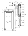
제1도는 본 발명의 자전거 프런트 서스펜션 포크의 일 실시예를 예시한 사시도.
제 2도는 제1도중 헤드튜브를 포함하여 댐퍼조절기 및 프런트 포크를 종방향으로 절개하여 프런트 서스펜션 포크의 일 실시예를 예시한 도면.
제 3도는 제1도중 프런트 서스펜션 포크의 중요 구성수단의 결합관계를 분해하여 나열한 사시도.
제 4도는 제3도중 본 발명의 댐퍼조절기에 있어서, 피스톤을 포함하는 시프트로드 및 댐퍼조절수단을 종방향에서 예시한 종단면도.
제 5도는 제3도중 댐퍼조절기의 댐퍼실린더를 예시한 종단면도 및 사시도.
제 6도는 제2도중 헤드튜브에 고정되게 결합되는 축수부재 및 고정수단으로 결합되는 로드헤드부재의 결합관계를 예시한 도면.
제 7도는 제2도중 프런프 포크의 포크헤드부재를 상세하게 예시한 도면.
제 8도는 제4도중 댐퍼조절기의 피스톤 및 댐퍼조절수단을 분해하여 그 결합관계를 예시한 사시도.
제 9도는 제4도중 피스톤 및 댐퍼조절수단을 종방향에서 일 실시예를 예시한 종단면도.
제 10도는 제4도중 시프트로드에 구성되는 로드헤드부재의 다른 실시예를 예시한 종단면도.
제 11도는 제3도중 자전거 핸들을 수용하는 스탬의 다른 일 실시예를 예시한 종단면도.
제 12도는 제2도중 댐퍼조절기의 댐퍼실린더와 피스톤 및 시프트로드의 다른 일 실시예를 예시한 종단면도.
제 13도는 제12도중 피스톤의 하면에 제공되는 오일링부재를 예시한 종단면도.
제 14도는 첨부도면 제7도에 예시되는 포크헤드부재의 다른 일 실시예를 예시한 도면.
제 15도는 본 발명의 서스펜션 포크 댐퍼조절기가 작동되는 일 실시예를 예시한 도면.
제 16도는 종래의 자전거 프런트 서스펜션 포크를 예시한 종단면도.1 is a perspective view illustrating an embodiment of a bicycle front suspension fork of the present invention.
2 is a view illustrating an embodiment of the front suspension fork by cutting the damper regulator and the front fork in the longitudinal direction including a head tube in the first view.
FIG. 3 is a perspective view of the first suspension in which the coupling relations of important components of the front suspension fork are disassembled and arranged.
4 is a longitudinal cross-sectional view illustrating a shift rod and a damper adjusting means including a piston in a longitudinal direction in the damper regulator of the present invention in FIG. 3.
5 is a longitudinal sectional view and a perspective view illustrating a damper cylinder of the damper regulator in FIG. 3;
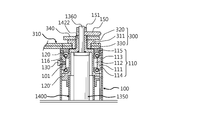
6 is a view illustrating a coupling relationship between a rod head member coupled to a water-reducing member and a fixing means fixedly coupled to a head tube in FIG. 2.
7 is a view illustrating in detail the fork head member of the front fork in FIG.
Figure 8 is a perspective view illustrating the coupling relationship by disassembling the piston and damper control means of the damper regulator in the fourth degree.
9 is a longitudinal cross-sectional view illustrating an embodiment in the longitudinal direction of the piston and damper adjustment means in the fourth.
10 is a longitudinal sectional view illustrating another embodiment of a rod head member configured in a shift rod in the fourth degree.
11 is a longitudinal cross-sectional view illustrating another embodiment of the stem for receiving the handlebar of the third road.
12 is a longitudinal cross-sectional view illustrating another embodiment of the damper cylinder and the piston and shift rod of the damper regulator in the second degree.
13 is a longitudinal sectional view illustrating an oil ring member provided on the lower surface of the piston in FIG. 12;
14 is a view illustrating another embodiment of the fork head member illustrated in FIG. 7 of the accompanying drawings.
15 is a view illustrating an embodiment in which the suspension fork damper regulator of the present invention is operated.
16 is a longitudinal sectional view illustrating a conventional bicycle front suspension fork.
본 발명의 자전거 프런트 서스펜션 포크은 첨부도면 제1도에 예시되는 바와같이 자전거의 헤드튜브(100) 내측에 프런트 서스펜션 포크의 댐퍼조절기(1000)가 제공되어 상기 헤드튜브(100) 내ㆍ외부로 왕복 작동됨과 아울러 헤드튜브(100) 내측에서 회동되게 구성되어 상기 댐퍼조절기(1000)의 하부에 자전거 전륜휠이 수용되는 프런트 포크(200)가 고정되게 결합되며, 또한 상기 댐퍼조절기(1000)의 댐퍼조작부(1360) 상기 헤드튜브(100) 상측으로 구성된채, 자전거 핸들이 수용되는 스탬 결합부재(310)과 고정수단(320)으로 고정되게 결합되어 상기 스탬 결합부재(310)을 회전하게 되면, 헤드튜브(100) 내측에서 상기 댐퍼조절기(1000)가 회동됨과 아울러 상기 프런트 포크(200)가 함께 회동된다.The bicycle front suspension fork of the present invention is provided with a
그리고 상기 댐퍼조절기(1000)의 상단으로 구성되는 댐퍼조작부(1360)가 상기 헤드튜브(100) 상단으로 돌출되게 배치된채, 상기 댐퍼조작부(1360)에 조절레바(150)가 고정되게 구성되어 상기 조절레바(150)를 회전시키면, 상기 댐퍼조절기(1000)의 댐퍼제어 조절수단이 연출되어 본 발명의 서스펜션 프런트 포크 댐퍼제어 조절이 연출되게 된다.And while the
바람직하게는 상기 헤드튜브(100) 외곽으로는 자전거 톱튜브(100a) 및 보텀튜브(100b)가 고정되게 결합되며, 또 바람직하게는 상기 프런트 포크(200)는 상기 댐퍼조절기(1000)와 결합되는 포크헤드부재(210)가 구성된채, 상기 포크헤드부재(210)에 파이프 형상의 프런트 튜브(230),(230')가 고정되게 결합됨과 아울러 상기 프런트 튜브(230),(230') 하부에는 자전거 전륜휠이 결합되는 휠고정부재(240),(240')가 구성되며, 더 바람직하게는 상기 포크헤드부재(210)에는 에어 주입수단(220)이 제공되어 상기 댐퍼조절기(100)를 포함하여 상기 프런트 튜브(230),(230')에 압축공기가 충전되는 특징으로 상기 프런트 튜브(230),(230')의 강성이 더 증가하게 된다.Preferably, the bicycle top tube (100a) and the bottom tube (100b) are fixedly coupled to the outside of the head tube (100), and preferably, the front fork (200) is coupled to the damper controller (1000). While the
상세하게는 첨부도면제 제2도 내지 제3도에 예시되는 바와같이, 자전거 프레임을 구성하는 헤드튜브(100) 내부 상측으로 축수부재(110)가 구성된채, 상기 축수부재(110) 하측으로 댐퍼제어가 연출되는 댐퍼조절기(1000)가 제공되는데 있어서,In detail, as illustrated in FIGS. 2 to 3 of the accompanying drawings, the water-
상기 댐퍼조절기(1000)는 헤드튜브(100) 내ㆍ외부로 출입되는 댐퍼실린더(1100) 및, 상기 댐퍼실린더(1100) 내ㆍ외부로 출입되는 시프트로드(1400)가 구성됨과 아울러 상기 시프트로드(1400) 상측에는; 고정체(1422)가 포함되는 로드헤드부재(1420)가 구성된채, 상기 고정체(1422)가 축수부재(110) 상측으로 관통되어 스템 결합부재(310)를 포함하는 스페이서링(330) 및 고정부재(320)로 구성되는 고정수단(300)으로 체결되며, 또한 상기 댐퍼실린더(1100) 하측에는 프런트 포크(200)가 결합되어 상기 프런트 포크(200)를 포함하는 상기 댐퍼실린더(1100) 및 시프트로드(1400) 내측에 압축유체가 저장된다.The
이로써, 상기 댐퍼조절기(1000)는 헤드튜브(100) 내측에 배치된채, 축수부재(110)의 상ㆍ하 베어링(120),(120') 및 고정수단(300)으로 회동되게 구성됨과 아울러 상기 댐퍼조절기(1000)는 압축유체의 팽창성 탄발력으로 댐퍼 완충제어가 연출되며, 또한 상기 프런트 포크(200)는 압축유체의 탄발력으로 그 강성이 더 증가되게 된다.Thus, the
그리고 상기 댐퍼실린더(1100)에 구성되는 커버부재(1120)에 키홈(1121a)이 형성되며, 또한 상기 로드헤드부재(1420)에 구성되는 베어링지지부(1423)에는; 상기 커버부재(1120)의 키홈(1121a)으로 출입되는 슬라이드 키(1500)가 고정되게 결합되어 상기 댐퍼실린더(1100)와 로드헤드부재(1420)가 함께 회동되게 된다.In addition, a
그러므로 상기 시프트로드(1400)에 구성되는 로드헤드부재(1420)와 상기 댐퍼실린더(1100)가 슬라이드 키(1500)에 의하여 회전이 방지된채, 함께 회동되게 되므로 상기 헤드튜브(100) 상측에 구성되는 스탬 결합부재(310)을 회전하게 되면, 상기 댐퍼조절기(1000)에 고정되게 결합되는 프런트 포크(200)가 함께 회동되게 된다.Therefore, the
또 그리고 상기 시프트로드(1400)의 하단에 피스톤(1200)이 구성되어 댐퍼실린더(1100) 내부에 배치된채, 상기 피스톤(1200)에는 첨부도면 제4도에 예시되는 바와같이 댐퍼조절부재(1350) 및 댐퍼조작부(1360)가 포함되는 댐퍼조절수단(1300)이 제공되어 상기 댐퍼조절수단(1300)의 제어조절에 따라 댐퍼조절기(1000)의 댐퍼 완충제어가 연출됨과 아울러 상기 시프트로드(1400)의 회동에 따라 댐퍼실린더(1100)를 포함하는 프런트 포크(200)가 헤드튜브(100) 내측에서 함께 회동되는 특징을 갖는다.In addition, the
바람직하게는 상기 댐퍼조절기(1000)는 첨부도면 제15도에 예시되는 바와같이 댐퍼실린더(1100) 내측에 댐퍼조절수단(1300) 및, 시프트로드(1400)가 결합된 피스톤(1200)이 배치되어 피스톤(1200) 하측으로 에어압력실(P1)이 형성된채, 피스톤(1200) 상측과 댐퍼실린더(1100)의 커버부재(1120) 사이에 오일압력실(P2)이 형성되며, 또한 상기 시프트로드(1400) 내측에 상기 에어압력실(P1)의 압축유체가 저장되는 에어댐퍼실(C1)이 형성되고, 상기 시프트로드(1400) 내측에는; 상기 댐퍼조절수단(1300)을 제어 조절하는 댐퍼조절부재(1350)가 구성된채, 상기 댐퍼조절부재(1350)의 내측에는 상기 오일압력실(P2)과 제한적으로 연통되는 오일챔버(C2)가 형성된다,Preferably, the
이로써, 상기 에어압력실(P1)과 에어댐퍼실(C1) 사이로 압축유체가 제한적으로 출입되는 특징으로 압축유체의 댐퍼작용이 연출되며, 또한 상기 오일압력실(P2)과 오일챔버(C2) 사이로 오일유체가 제한적으로 출입되는 특징으로 오일유체의 댐퍼작용이 함께 연출되는 압축유체와 오일유체의 복합적인 댐퍼작용이 이루어지게 된다.As a result, a damping action of the compressed fluid is produced by the feature that the compressed fluid is restricted between the air pressure chamber (P1) and the air damper chamber (C1), and there is also oil between the oil pressure chamber (P2) and the oil chamber (C2). It is a feature that the fluid is restricted in and out, and a complex damper action between a compressed fluid and an oil fluid, in which the damping action of the oil fluid is produced together, is achieved.
아울러 상기 프런트 포크(200)는; 자전거 전륜휠을 지지하는 한 쌍의 포크튜브(230),(230') 상단부에 포크헤드부재(210)가 구성되어 상기 포크튜브들(230),(230')에는 에어탱크(T1),(T1')가 형성되며, 또한 상기 포크헤드부재(210)에는 에어 주입수단(220)이 제공된채, 상기 댐퍼실린더(1100)가 상기 포크헤드부재(210)에 고정되게 결합되어 상기 에어댐퍼실(C1)의 압축유체가 댐퍼실린더(1100)의 에어압력실(P1)에 배치되는 에어호수(1160)를 통하여 상기 에어탱크(T1),(T1')로 출입되게 된다.In addition, the
그러므로 에어압력실(P1)에 저장되는 압축유체는 상기 댐퍼조절수단(1300)을 통하여 에어댐퍼실(C1)과 제한적으로 출입되며, 또한 상기 에어댐퍼실(C1)과 에어챔버(T1),T1')가 상호 연통되게 되므로 상기 에어댐퍼실(C1)의 압축유체 저장 능력이 더 크게 증가되어 본 발명의 댐퍼조절기 압축유체의 댐퍼작용이 완만하게 연출됨과 아울러 상기 프런트 포크(200)의 포크튜브(230),(230')는 압축유체에 의하여 강성력이 더 증가되게 된다.Therefore, the compressed fluid stored in the air pressure chamber (P1) is limitedly in and out of the air damper chamber (C1) through the damper control means (1300), and also the air damper chamber (C1) and the air chamber (T1), T1') Since it is in communication with each other, the storage capacity of the compressed fluid in the air damper chamber (C1) is significantly increased, so that the damper action of the compressed fluid of the damper regulator of the present invention is gently produced, and the
여기서 상기 프런트 포크의 포크튜브는 특정 재질에 국한 되는 것이 아니고 알루미늄 파이프를 포함하여 카본, 티타늄, 스틸, 강화플라스틱, 대나무 등등의 다양한 재질을 이용할 수 있음은 자명한 사실이다.Here, the fork tube of the front fork is not limited to a specific material, and it is obvious that various materials such as carbon, titanium, steel, reinforced plastic, bamboo, etc. can be used, including aluminum pipes.
또 바람직하게는 상기 시프트로드(1400/1410) 상단에 구성되는 로드헤드부재(1420/1421))의 고정체(1422) 중심으로 관통구(1424)가 형성되며, 또한 상기 댐퍼조절부재(1350)의 상단부에는 댐퍼조작부(1360)가 고정되게 결합된채, 상기 로드헤드부재(1420)의 고정체(1422) 상부로 돌출되게 구성되는 특징으로 상기 댐퍼조작부(1360)를 회전하게 되며, 상기 댐퍼조절수단(1300)이 제어 조절되어 압축유체의 댐퍼작용과 오일유체의 댐퍼조절 작용이 함께 이루어지는 특징을 갖는다.In addition, preferably, a through
이하 본 발명의 프런트 서스펜션 포크의 헤드튜브와 댐퍼조절기의 결합관계에 대하여 첨부도면 제2도 내지 제3도 및 제6도 의거 상세히 설명하면 다음과 같다.Hereinafter, the coupling relationship between the head tube of the front suspension fork of the present invention and the damper regulator will be described in detail with reference to FIGS. 2 to 3 and 6 of the accompanying drawings.
첨부도면 제2도 내지 제3도에 예시되는 바와같이 상기 헤드튜브(100) 상부 내측에는 축수부재(110)가 고정되게 결합된채, 상기 축수부재(110)의 상측과 하측에는 상ㆍ하 베어링(120),(120')이 배치되는데 있어서,As illustrated in FIGS. 2 to 3 of the accompanying drawings, the upper and lower bearings of the upper and lower sides of the
첨부도면 제6도에 예시되는 바와같이 상기 축수부재(110)는; 내경부(112)가 형성되는 관통체(111)가 구성되어 상기 관통체(111)의 내경부(112) 상측으로 직경이 확장되는 상부경사면(113)이 형성된채, 상단으로 공간부가 형성되는 상부내경면(115)이 형성되어 상부베어링(120)이 배치되며, 또한 상기 축수부재(110)의 관통체(111) 하측으로 직경이 확장되는 하부경사면(114)이 형성되어 상기 하부베어링(120')이 배치된채, 상기 축수부재(110)의 관통체(111) 외주면에서 내측으로 체결홀(116)이 형성된다.As illustrated in Figure 6 of the accompanying drawings, the water-
그러므로 상기 헤드튜브(100)의 상측 외주면에 고정홀(101)이 형성된채, 상기 축수부재(110)는 상기 축수부재(110)의 체결홀(116)과 결합되어 고정부재(130)에 의하여 고정되게 결합되며, 또한 축수부재(110)가 상기 헤드튜브(100) 내측에 접착제등으로 고착되는 결합방식으로 고정되게 결합된다.Therefore, while the fixing
이로써 첨부도면 제2도 내지 제4도에 예시되는 바와같이 상기 시프트로드(1400) 상단부에 구성되는 로드헤드부재(1420)에는; 하측으로 직경이 확장되는 베어링지지부(1423)가 구성된채, 상기 축수부재(110)의 하부 베어링(120')과 회동되게 결합되며, 또한 로드헤드부재(1420)의 고정체(1422)는 축수부재(110) 및 상부베어링(120') 상측으로 관통된채, 상기 고정체(1422)에 자전거 핸들이 수용되는 스템 결합부재(310)를 포함하여 스페이서링(330) 및 고정부재(320)로 구성되는 고정수단(300)이 고정되게 결합되어 상기 로드헤드부재(1420)는 축수부재(110)의 상ㆍ하 베어링(120),(120')에 회동되게 결합된다.Thus, as illustrated in FIGS. 2 to 4 of the accompanying drawings, the
그러므로 스템 결합부재(310)의 회동에 따라 상기 시프트로드(1400) 및 댐퍼실린더(1100)는 헤드튜브(100) 내측에서 함께 회동되는 특징을 갖는다.Therefore, according to the rotation of the
여기서 상기 헤드튜브는 특정 재질에 국한 되는 것이 아니고 알루미늄 파이프를 포함하여 카본, 티타늄, 스틸, 강화플라스틱, 대나무 등등의 다양한 재질을 이용할 수 있음은 자명한 사실이다.Here, it is obvious that the head tube is not limited to a specific material, and various materials such as carbon, titanium, steel, reinforced plastic, and bamboo can be used, including aluminum pipes.
또 상세하게는 첨부도면 제6도에 예시되는 바와같이 상기 축수부재(110)의 상부 베어링(120) 상면에 상기 고정수단(300)으로 구성되는 스페이서링(330) 및 스템 결합부재(310/311)가 배치된채, 상기 고정수단(300)으로 구성되는 고정부재(320)가 로드헤드부재(1420)의 고정체(1422)에 체결됨과 아울러 스템 결합부재(310) 상단에 밀착되게 결합되어 스템 결합부재(310/311) 및 고정부재(320)가 상기 로드헤드부재(1420)의 고정체(1422)에 고정되게 결합된다.In detail, as illustrated in FIG. 6 of the accompanying drawings, the
바람직하게는 로드헤드부재의 고정체(1422) 상측에 원판형상의 잠금부재(340가 체결됨과 아울러 상기 고정부재(320)에 고정되게 결합되어 고정부재(320)의 체결상태가 유지되며, 또한 상기 댐퍼조작부(1360)에는 조절레바(150)가 고정너트(151)에 의하여 고정되게 결합된다.Preferably, a locking
그러므로 자전거 핸들이 수용되는 스템 결합부재(310/311)는 시프트로드(1400)가 고정되게 결합된 로드헤드부재(1420)의 고정체(1422)에 고정되게 결합되어 조절레바(150)를 회전하게 되면, 댐퍼조작부(1360)의 회전에 따라 댐퍼조절부재(1350) 및 댐퍼조절수단이 제어 조절되는 특징을 갖는다.Therefore, the
상술한 헤드튜브 상측에서 댐퍼조절기와 고정되게 결합되는 자전거 핸들이 수용되는 스템 결합부재(310) 대하여 더 상세하게 설명하기로 한다.It will be described in more detail with respect to the
첨부도면 제2도 내지 제3도에 예시되는 바와같이 판재로 구성되는 스탬 결합부재(311)의 일측(우측)에는 상기 시프트로드(1400)의 로드결합부(1420)에 장착되는 관통구(312)가 형성되며, 또한 상기 스탬 결합부재(311)의 타측에는 상기 자전거 핸들이 수용 장착되는 원통결합부(314)가 구성된채, 상기 원통결합부(314)의 단부에 상기 원통결합부(314)를 클램핑 체결하는 체결홀(315)이 형성되어 고정부재(316)의 체결에 의하여 상기 원통결합부(314)의 내측에 형성되는 공간부(313)에 자전거 핸들(도시하지 않음)이 수용된채, 고정되게 된다.As illustrated in FIGS. 2 to 3 of the accompanying drawings, a through
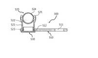
이하 헤드튜브 상측에서 댐퍼조절기와 고정되게 결합되는 스템의 다른 일 실시예를 설명하기로 한다.Hereinafter, another embodiment of the stem fixedly coupled to the damper regulator from the upper side of the head tube will be described.
첨부도면 제11도에 예시되는 바와같이 상기 스템 결합부재(510)는; 일측에 관통구(511)가 형성된채, 상기 관통구(511) 타측으로 결합구(512)가 형성된 판재로 구성되어 첨부도면 제6도에 예시되는 바와같이 고정수단(300)의 고정부재(320)가 상기 스탬 결합부재(510)의 관통구(511)로 관통되어 상기 고정부재(320)에 의하여 로드헤드부재(1420)의 고정체(1422) 상측에 고정되게 결합된다.As illustrated in Figure 11 of the accompanying drawings, the
그리고 상기 스템 결합부재(510)의 결합구(512)에는 자전거 핸들이 수용되는 스템(520)이 장착되어 상기 스템(520)의 하부 내측에 형성되는 체결부(523)에 체결부재(530)가 결합된채, 상기 스템 결합부재(510)의 하단에 밀착되게 결합되는 특징으로 상기 스템(520)이 로드헤드부재에 고정되게 결합되게 된다.And the
상세하게는 상기 스템(520)은; 내부에 공간부를 갖는 원통체(521)가 입설된채, 상기 원통체(521) 상측으로 반원형의 하부결합체(522) 및 반원형의 상부결합체(524)가 고정부재(525)로 고정되어 상기 스템(520)이 구성되게 된다.Specifically, the
이하 본 발명의 프런트 서스펜션 포크의 프런트 포크에 대하여 첨부도면 제2도 내지 제3도 및 제7도 의거 상세히 설명하면 다음과 같다.Hereinafter, the front fork of the front suspension fork of the present invention will be described in detail with reference to FIGS. 2 to 3 and 7 of the accompanying drawings.
첨부도면 제2도에 예시되는 바와같이 프런트 포크(200)는; 상기 포크헤드부재(210) 양측 하부에 튜브결합홀(213),(213')이 형성되어 포크튜브(230),(230')가 고정되게 결합된채, 포크튜브(230),(230') 하단에는 상기 에어탱크(T1),(T1')가 밀폐됨과 아울러 자전거 전륜휠이 결합되는 휠고정부재(240)가 결합체(241),(241')에 의하여 고정되게 결합되는데 있어서,The
첨부도면 제7도에 예시되는 바와같이 상기 포크헤드부재(210)의 몸체(211) 상면 중심으로 결합홀(212)이 형성되며, 또한 포크헤드부재(210)의 몸체(211) 하면 중심으로 상기 결합홀(212)과 연통되는 에어출입구(214)가 형성되어 상기 에어출입구(214)에서 상기 튜브결합홀(213),(213') 각각으로 압축유체가 출입되는 수평형식의 개방유로(215) 및 경사지는 터널유로(216),(216')가 형성된채, 포크헤드부재(210)의 하면에는; 상기 개방유로(215)를 외부로부터 차단되게 하는 커버부재(218)가 결합되어 상기 개방유로(215)는 외부로부터 밀폐되는 특징으로 상기 결합홀(211)과 튜브결합홀(213),(213')은 상호 연통되어 압축유체가 출입되게 된다.As illustrated in FIG. 7 of the accompanying drawings, a
바람직하게는 포크헤드부재(210)의 일측 튜브결합홀(213') 상부에는; 압축공기가 주입되는 에어 주입수단(220)이 제공되며, 또한 상기 결합홀(212) 외곽에 체결홀(217),(217')이 형성됨과 아울러 상기 결합홀(212) 외곽에는 실링부(212a)가 형성되어 첨부도면 제15도에 예시되는 바와같이 상기 포크헤드부재(210)에 댐퍼실린더(1400)가 결합되게 되면 압축유체의 누설이 방지되게 된다.Preferably on one side of the tube coupling hole 213' of the
그러므로 첨부도면 제3도에 예시되는 바와같이 상기 포크헤드부재(210)의 결합홀(212)에 상기 댐퍼실린더(1100)가 밀착되게 배치된채, 상기 댐퍼실린더(1100) 하측 외주에 구성되는 고정부재(1130)가 상기 포크헤드부재(210)의 체결홀(217),(217')에 고정되게 결합되어 상기 댐퍼조절기(1000)에 프런트 포크(200)가 고정되게 결합되며, 또한 첨부도면 제15도에 예시되는 바와같이 상기 에어압력실(P1)과 오일탱크(T1),(T1')는 상호 연통되어 압축유체가 출입되는 특징을 갖는다.Therefore, as illustrated in FIG. 3 of the accompanying drawings, the
한편, 상기 포크헤드부재의 다른 일 실시예를 설명하기로 한다.Meanwhile, another embodiment of the fork head member will be described.
첨부도면 제14도는 첨부도면 제7도에 예시되는 포크헤드부재의 다른 일 실시예를 예시한 도면으로 상기 포크헤드부재(400)는; 상부포크부재(410)와 하부포크부재(420)로 구성된채, 상부포크부재(410)와 하부포크부재(420)의 양측에는 상기 포크튜브(230),(230')가 수용되는 결합부재(430)가 고정되게 결합되어 상부포크부재(410)와 하부포크부재(420)는 소정의 간격으로 이격되게 구성되며, 또한 상기 상부포크부재(410)의 중심으로 결합구(411)가 형성된채, 상기 댐퍼실린더(1100)가 관통되어 상기 하부포크부재(420)의 중심으로 형성되는 결합홀(421)에 밀착되게 결합된다.Attached Figure 14 is a view illustrating another embodiment of the fork head member illustrated in Figure 7 of the accompanying drawings, the
그리고 상기 상부포크부재(410)와 하부포크부재(420)에는 상호 연통되어 압축유체가 출입되는 연통부재(470),(470')가 제공된채, 하부포크부재(420)에는; 압축유체가 출입되는 에어출입구(423)을 포함하여 에어유로(424) 및 유출입구(425),(425')가 형성되며, 또한 상부포크부재(410)에는; 연통로(461),(461')가 형성된채, 제14도중 "도14-1" 에 예시되는 바와같이 체결구(413)가 형성되어 상기 댐퍼실린더(1100)의 고정부재(1130)가 고정볼트에 의하여 상부포크부재(410)에 고정되게 결합된다.In addition, the
바람직하게는 상기 결합부재(430)는 하측 단부가 개방되는 원통홀(430a),(430a')이 형성되어 상기 포크튜브(230),(230)가 고정되게 수용되며, 또한 상기 결합부재(430)의 하측 외주면에는 첨부도면 제14도중 "도14-3"에 예시되는 바와같이 나사체결부(433)가 형성된채, 결합부재(430)의 상면(432)에는 고정홀(434) 및 에어출입구(435)가 형성된다.Preferably, the
그리고 첨부도면 제14도중 "도14-2"에 예시되는 바와같이 상기 하부포크부재(420)의 양측으로 체결구(422)가 형성되어 상기 결합부재(430),(430')가 고정되게 체결되며, 또한 첨부도면 제14도중 "도14-1"에 예시되는 바와같이 상부포크부재(410)의 하부 양측으로 결합홀(412),(412') 및 결합구(414),(414')가 형성되어 상기 결합부재(430),(430')가 상기 결합홀(412),(412')에 밀착되게 결합된채, 결합부재(430),(430')의 내측에서 상부포크부재(410)의 상단으로 고정부재(450),(450')가 체결되는 특징으로 하부포크부재(420)가 상부포크부재(410)에 고정되게 결합된다.And, as illustrated in "FIG. 14-2" in FIG. 14 of the accompanying drawings,
또 바람직하게는 상부포크부재(410)의 하면과 하부포크부재(420)의 상면으로 상기 연통부재(470),(470')가 제공되는데 있어서, 상기 하부포크부재(420)의 하면에는; 상기 하부포크부재(420)의 결합홀(421)과 연통되는 에어출입구(423)가 형성된채, 하부포크부재(420)의 하면에는 개방된 에어유로(424)가 형성되는 커버부재(440)가 고정되게 결합되어 상기 유출입구(425),(425')와 상기 연통부재(470),(470')는 상호 연통되며, 상기 상부포크부재(410)의 상면에는 상기 결합부재(430),(430),의 내부와 연통되는 연통구(415),(415') 및 출입구(416)(416')가 각각 형성된채, 커버(460),(460')로 결합되어 상기 연통로(461),(461)가 밀폐되는 특징으로 상기 하부포크부재(420)의 결합홀(421)에서 상기 결합부재(430),(430') 내측으로 압축유체의 출입이 이루어지는 특징을 갖는다.In addition, preferably, the lower member of the
그러므로 상기 포크헤드부재(400)는 상부포크부재(410)와 하부포크부재(420)의 판재로 구성된채, 소정의 간격으로 이격되게 구성되어 포크헤드부재(400)의 무게를 감소하게 되며, 또한 상기 상ㆍ하포크부재는 판재로 구성되어 제조 작업성이 간단하게 이루어진다.Therefore, the
이하 본 발명의 댐퍼조절기에 있어서, 시프트로드와 댐퍼실린더가 함께 회동되는 일 실시예를 상세하게 설명하기로 한다.Hereinafter, an embodiment in which the shift rod and the damper cylinder are rotated together will be described in detail in the damper controller of the present invention.
댐퍼조절기(1000)의 댐퍼실린더(1100)에 구성되는 커버부재(1120)의 외곽에는 첨부도면 제3도 및 제5도에 예시되는 바와같이 수직으로 개방되는 다 수개의 키홈(1121a)이 형성되고, 또한 시프트로드(1400) 상면에 고정되게 결합되는 로드헤드부재(1420)에는; 첨부도면 제3도 및 제4도중 "도4-1"에 예시되는 바와같이 상기 축수부재(110)의 하부 베어링(120)에 결합되는 베어링지지부(1423)가 구성된채, 상기 베어링지지부(1423) 외곽에는 다 수개의 키홈(1423a) 및 고정홀(1423b)이 형성되게 된다.On the outer side of the
그러므로 상기 로드헤드부재(1420)의 베어링지지부(1423)에 형성되는 키홈(1423a) 및 고정홀(1423b)에 슬라이드 키(1500)가 고정볼트(도시하지 않음)로 고정되게 결합되어 첨부도면 제3도에 예시되는 바와같이 다 수개의 슬라이드 키(1500)가 상기 커버부재(1120)의 키홈(1421a)으로 슬라이딩되게 출입되며, 이로써 상기 로드헤드부재(1420)의 회전에 따라 상기 로드헤드부재(1420)에 고정되게 결합되는 시프트로드(1400)와 댐퍼실린더(1100)가 함께 회동된다.Therefore, the
이와 함께 상기 로드헤드부재(1420)는 상술한 바와같이 상기 헤드튜브(100)의 축수부재(110)의 상ㆍ하 베어링(120),(120') 및 고정수단(300)으로 회동되게 결합되어 상기 스템 결합부재(310)를 회전하게 되면, 상기 댐퍼실린더(1100)가 함께 회동되게 된다.In addition, the
이하 본 발명의 댐퍼조절기에 있어서, 댐퍼실린더의 일 실시예를 상세하게 설명하기로 한다.Hereinafter, in the damper regulator of the present invention, an embodiment of the damper cylinder will be described in detail.
첨부도면 제5도에 예시되는 바와같이 댐퍼실린더(1100)를 구성하는 실린더 튜브(1110)의 상측 외주에 결합체(1111)가 구성되어 커버부재(1120)가 고정되게 결합된채, 상기 커버부재(1120)의 외주면에는 수직으로 개방되는 다 수개의 키홈(1121a)이 형성되며, 또한 커버부재(1120)의 내측에는; 부싱부재(1122)가 고정되게 결합되어 오일패킹(1124) 및 오일링(1123)이 장착되게 된다.As illustrated in FIG. 5 of the accompanying drawings, the
상세하게는 상기 댐퍼실린더(1100)의 커버부재(1120) 내측 하부에는 오일패킹(1124)이 장착된채, 상기 오일패킹(1124) 상단에 상기 부싱부재(1122)가 배치되며, 또한 첨부도면 제5도중 "도5-1"에 예시되는 바와같이 커버부재(1120)의 내주면 일측과 부싱부재(1122)의 외주면 일측이 함께 공유되는 고정볼트홀(1125)이 형성된채, 고정볼트(도지하지 않음)가 체결되어 상기 부싱부재(1122)가 커버부재의 몸체(1121) 내측에 결합되게 된다.In detail, the
그리고 상기 실린더 튜브(1110) 하측 외주에는; 직경이 확장되는 결합체(1112)가 구성된채, 상기 프런트 포크(200)와 결합되는 고정부재(1130)가 실린더 튜브(1110) 하측에 고정되게 결합되어 상기 고정부재(1130)의 양측으로 고정홀(1132)이 마주 보도록 형성되며, 또한 실린더 튜브(1110) 하측 내부에는; 체결홀(1141)이 형성되는 헤드부재(1140)가 결합되어 상기 댐퍼실린더(1100) 내부가 밀폐되는 특징을 갖는다.And on the lower circumference of the
바람직하게는 첨부도면 제15도에 예시되는 바와같이 댐퍼실린더(1100) 내측에 제공되는 피스톤(1200) 하면에는: 나선형의 에어호수(1160)가 구성된 일측의 에어연결부재(1161)가 고정되게 결합되며, 또한 에어호수(1160)의 타측 에어연결부재(1162)는 상기 헤드부재(1140)의 체결홀(1141)에 고정되게 결합되어 상기 에어호수(1160)는 댐퍼실린더(1100)의 에어압력실(P1)에서 상ㆍ하로 가변되는 나선형으로 배치되게 된다.Preferably, as illustrated in FIG. 15 of the accompanying drawings, the lower surface of the
그러므로 상기 에어호수(1160)을 통하여 에어댐퍼실(C1)과 에어탱크(T1),(T1')로 압축유체가 출입되며, 또 상기 에어댐퍼실(C1)에서 에어압력실(P1)로 압축유체가 복귀되는 과정에 압축유체의 댐퍼작용이 이루어지게 된다.Therefore, the compressed fluid enters and exits the air damper chamber (C1) and the air tanks (T1) and (T1') through the air lake (1160), and the compressed fluid from the air damper chamber (C1) to the air pressure chamber (P1). During the return process, the damping action of the compressed fluid is made.
또 바람직하게는 첨부도면 5도에 예시되는 바와같이 댐퍼실린더(1100)의 실린더 튜브(1110) 상측 결합체(1111)와 하측 결합체(1112) 사이의 외주면에는; 첨부도면 제5도중 "도5-1" 에 예시되는 바와같이 고장력 합사줄(1150)이 나선형으로 밀착되게 권취된채, 고장력 합사줄(1150)의 양단부에는 접착재가 도포되어 상기 합사줄(1150)의 권취상태를 유지하게 된다.In addition, preferably, as illustrated in the accompanying drawing 5, the outer peripheral surface between the
이로써 댐퍼실린더(1100) 외주면에 밀착되게 권취되는 가볍고, 인장강도가 큰 합사줄에 의하여 상기 댐퍼실린더(1100) 내측에서 형성되는 압축유체 및 오일유체의 압력에 따른 댐퍼실린더(1100)가 외주면으로 변형되는 내압성이 증가되는 특징을 갖게 된다.As a result, the
여기서 상기 고장력 합사줄은 통상적으로 고강도 피아노선을 포함하여 낚시줄에 사용되는 합사 낚시줄, 고장력 섬유로프 등등의 다양한 재질이 사용될 수 있음은 자명한 사실이다.Here, it is obvious that the high-strength yarn line can be used in various materials such as a high-strength piano wire, a high-strength fishing line, a high-strength fiber rope, and the like.
상술한 본 발명 댐퍼조절기의 구성 및 댐퍼작용에 대하여 상세히 설명하면 다음과 같다.The configuration and damper operation of the damper regulator of the present invention described above will be described in detail as follows.
첨부도면 제15도에 예시되는 바와같이 상기 댐퍼실린더(1100) 내측에는; 에어압력실(P1)과 에어댐퍼실(C1)로 압축유체가 제한적으로 출입됨과 아울러 오일압력실(P2)과 오일챔버(C2)로 오일유체가 제한적으로 출입되는 피스톤(1200)이 제공되는데 있어서, 피스톤(1200) 상면으로 시프트로드(1400)가 고정되게 결합되어 에어댐퍼실(C1)이 형성되며, 또한 상기 피스톤(1200)에 제공되는 댐퍼조절수단(1300) 상단에 댐퍼조절부재(1350)가 고정되게 결합되어 오일챔버(C2)가 형성된채, 상기 댐퍼조절부재(1350)의 상단에 댐퍼조작부(1360)가 고정되게 결합되어 로드헤드부재(1420)의 관통구(1424) 상측으로 밀착 슬라이딩되게 관통된다.As illustrated in FIG. 15 of the accompanying drawings, the
그러므로 상기 에어댐퍼실(C1)이 밀폐됨과 아울러 댐퍼조작부(1360)를 회전하게 되면, 댐퍼조절기(1000)의 댐퍼조절부재(1350) 및 댐퍼조절수단(1300)이 회동되어 댐퍼제어 조절이 연출된다.Therefore, when the air damper chamber C1 is closed and the
상세하게는 첨부도면 제4도에 예시되는 바와같이 상기 피스톤(1200) 상측 외주면에는; 로드체결부(1220)가 구성되어 상기 로드체결부(1220) 내측 상면에 오일유체 및 압축유체의 댐퍼작용을 조절하는 댐퍼조절수단(1300)이 회동되게 배치되며, 또한 상기 댐퍼조절수단(1300) 상측 외주면에 결합체(1320)가 구성되어 상기 댐퍼조절부재(1350)가 고정되게 결합된채, 상기 댐퍼조절부재(1350) 내측에 프리 피스톤(1370)이 장착되는 가변 오일챔버(C2)가 형성된다.Specifically, as illustrated in FIG. 4 of the accompanying drawings, the
그리고 상기 프리 피스톤(1370) 상측의 댐퍼조절부재(1350) 외주에는 압축유체가 출입되는 출입구(1351)가 형성된채, 상기 댐퍼조작부(1360)가 고정되게 결합된다.In addition, the
바람직하게는 상기 댐퍼조작부(1360)의 하단부에는 상기 댐퍼조절부재(1350)의 상단부를 밀폐되도록 차단되게 함과 아울러 상기 로드헤드부재(1420)의 고정체(1422) 내측에 형성되는 관통구(1424)를 통하여 압축유체의 누설을 방지하는 댐퍼조작부 몸체(1361)가 구성된채, 상기 로드헤드부재(1420)의 고정체(1422) 하면에 밀착 슬라이딩 되게 배치되어 상기 댐퍼조작부(1360) 및 댐퍼조절부재(1350)는 시프트로드(1400) 내측에서 회동되게 된다.Preferably, the lower end of the
또 그리고 상기 피스톤(1200)의 로드체결부(1220)에 상기 시프트로드(1400)가 고정되게 체결되어 시프트로드(1400) 내측에 상기 에어댐퍼실(C1)이 형성됨과 아울러 상기 댐퍼조절부재(1350)가 배치되며, 또한 상기 시프트로드(1400) 상측에는 로드헤드부재(1420)가 고정되게 결합된채, 상기 로드헤드부재(1420)의 고정체(1422)에 관통구(1424)가 형성되어 상기 관통구(1424) 내측으로 상기 댐퍼조작부(1360)가 관통된다.In addition, the
그러므로 로드헤드부재(1420)의 고정체(1422) 상측으로 상기 댐퍼조작부(1360)가 돌출되게 구성되는 특징으로 댐퍼조작부(1360)의 회전에 따라 압축유체의 댐퍼작용과 오일유체의 댐퍼작용이 함께 이루어지는 특징을 갖는다.Therefore, the
바람직하게는 상기 피스톤(1200)의 몸체(1210)의 외주에는 오일링(1230)이 제공되어 상기 오일링(1230) 상측으로 오일유체를 제한적으로 출입되게 하는 오일유출로(1219) 및 오일유입로(1216)가 형성된채, 상기 오일유입로(1217)에는 첵크발브(1250)가 제공되는데 있어서 상기 오일유출로(1219)와 오일유입로(1217)는 피스톤 몸체(1210)의 상면과 연통되는 수직유로(1216)가 형성되게 된다.Preferably, an
한편 본 발명 댐퍼조절기의 댐퍼실린더에 제공되는 피스톤 및 시프트로드의 구성에 있어서, 다른 일 실시예를 설명하기로 한다.On the other hand, in the configuration of the piston and the shift rod provided in the damper cylinder of the present invention damper regulator, another embodiment will be described.
첨부도면 제12도에 예시되는 바와같이 댐퍼실린더(1100)의 내경 중심선(CL1)은 댐퍼실린더(1100)의 커버부재(1120) 내경 및 시프트로드(1400)의 외경 중심선(CL3)에서 소정의 간격(CL1+1)으로 편심되게 형성되며, 또한 "도12-2" 에 예시되는 바와같이 피스톤(1200)의 외경 중심선(CL2)은 피스톤(1200)의 로드체결부(1220)의 중심선(CL4) 중심선에서 소정의 간격(CL1+1)으로 편심되게 형성된다.As illustrated in FIG. 12 of the accompanying drawings, the inner diameter center line CL1 of the
그리고 상기 피스톤(1200)의 하측 외주에는 직경이 단차지게 작게 형성되는 오일링결합부(1210a)가 구성되어 상기 댐퍼실린더(1100) 내측에 가압되어서 밀착되는 오일링(1230a)이 결합되며, 또한 피스톤(1200) 하면에는; 상기 오일링(1230a)의 하단부에 밀착되게 가압되는 원판형상의 오일링부재(1270)가 배치된채, 고정부재(1240)로 고정되게 결합된다.And the lower outer periphery of the
이로써, 상기 피스톤(1200)의 하측에 고정되게 제공되는 오일링(1230a)의 중심선(CL1/CL2)과 상기 시프트로드의 중심선(CL3)이 상호 편심(CL1+1)지게 형성되는 특징으로 시프트로드(1400)의 회전에 따라 상기 댐퍼실린더(1100) 내측에서 상기 피스톤(1200)의 회전이 방지된채, 상기 댐퍼실린더(1100)가 함께 연동되는 특징을 갖는다.As a result, the shift rod is characterized in that the center line CL1/CL2 of the
바람직하게는 상기 피스톤(1200)의 하면에 체결홀(1211f)이 형성된채, 상기 피스톤(1200)의 하면에는; 첨부도면 제13도에 예시되는 바와같이 상기 체결홀(1211f)에 고정되게 결합되는 내통구(1281)가 형성된 원판형상의 오일링부재(1280)가 배치되어 고정부재(1240)에 의하여 상기 피스톤(1200) 하면에 고정되게 결합되며, 상기 오일링부재(1280)의 외주면에 원주상으로 원형요홈(1282)이 형성되어 오일링부재(1280)의 외주면에 댐퍼실린더(1100) 내측에 가압되어서 밀착되는 오일링(1230a)이 고정되게 배치되는 특징으로 상기 오일링(1280)의 중심선CL1/CL2과 상기 시프트로드(1400)의 중심선(CL3)이 상호 편심(CL1+1)지게 형성되어 상술한 바와같이 상기 시프트로드(1400)의 회전에 따라 피스톤(1200)의 회전이 방지된채, 댐퍼실린더(1100)가 함께 연동되는 특징을 갖는다.Preferably, while the
상세하게는 첨부도면 제12도중 "도12-3"에 예시되는 바와같이 오일링부재(1240)의 내측에는 상기 체결홀(1211f)에 결합되는 고정홀(1271)이 형성된 내면체(1272)가 구성됨과 아울러 오일링부재(1270)의 외측에는 상기 오일링(1230a)이 결합되는 외면체(1273)가 구성된채, 상기 내면체(1272)와 외면체(1273)에는 다 수개의 연결체(1274)로 구성되어 상기 피스톤(1200) 하면의 일부가 개방되게 된다.Specifically, as illustrated in "FIG. 12-3" of FIG. 12 of the accompanying drawings, an
또 한편 상기 시프트로드의 상측에 고정되게 결합되는 로드헤드부재의 다른 일 실시예를 설명하기로 한다.On the other hand, another embodiment of the rod head member fixedly coupled to the upper side of the shift rod will be described.
첨부도면 제10도에 예시되는 바와같이 시프트로드(1400)의 몸체(1410) 상부 내측으로 나사체결홀(1410a)이 형성되고, 상기 로드헤드부재(400의 외주에는 나사체결부(1421a)가 구성되어 시프트로드 몸체(1410)의 나사체결홀(1410a)에 결합되며, 또한 로드헤드부재(1420)의 나사체결부(1420a)에 상기 축수부재의 하부 베어링에 결합되는 베어링지지부재(1430)가 결합된채, 상기 베어링지지부재(1430)가 시프트로드 몸체(1410) 상단에 밀착되게 결합되어 체결된다.As illustrated in FIG. 10 of the accompanying drawings, a
상세하게는 상기 로드헤드부재 몸체(1421) 내측에는 상기 에어댐퍼실(C1)이 확장되는 공간부(1423)가 형성됨과 아울러 로드헤드부재 몸체(1421)의 상측으로 구성되는 고정체(1422) 내측에는 관통부(1424)가 형성된채, 상기 고정체(1422) 하면에는 오일실링홈(1425)이 형성되게 된다.Specifically, inside the rod
바람직하게는 상기 베어링지지부재(1430)는 첨부도면 제10도중 "도10-1" 에 예시되는 바와같이 베어링지지부재(1430)의 외곽으로 상면과 하면이 개방되는 다 수개의 키홈(1431)이 형성된채, 상기 키홈(1431)에 고정홀(1432)이 형성되어 상기 각각의 키홈(1431)에 첨부도면 제3도에 예시되는 바와같이 슬라이드 키(1500)가 고정되게 결합된다.Preferably, the bearing
이로써 상기 로드헤드부재(1420)는 상기 시프트로드 몸체(1410) 상단에서 나사체결 방식으로 결합되어 상기 로드헤드부재(1420)의 높낮이 조절이 가능하며, 무엇보다 상기 로드헤드부재(1420)의 구성이 간단하여 제작작업성이 용이하게 되며, 바람직하게는 상기 베어링지지부재(1430)는 상기 로드헤드부재(1420)의 나사체결 이완 및 풀림을 방지하는 로킹 너트방식으로 체결되게 된다.Thus, the
이하 본 발명의 댐퍼조절기의 댐퍼조절 제어를 위한 구체적인 바람직한 일 실시예를 상세히 설명하기로 한다.Hereinafter, a specific preferred embodiment for controlling damper control of the damper controller of the present invention will be described in detail.
먼저 본 발명 댐퍼조절기의 댐퍼조절 제어를 위한 압축유체 댐퍼작용에 대하여 설명하기로 한다.First, the compressed fluid damper for controlling the damper control of the damper regulator of the present invention will be described.
첨부도면 제15도에 예시되는 바와같이 댐퍼조절기(1000)의 에어압력실(P1)과 에어댐퍼실(C1)이 제한적으로 연통되고, 에어댐퍼실(C1)과 에어탱크(T1),(T1')가 연통되어 압축유체의 댐퍼작용이 연출되는데 있어서,As illustrated in FIG. 15 of the accompanying drawings, the air pressure chamber (P1) and the air damper chamber (C1) of the
첨부도면 제4도 및 제8도 내지 제9 에 예시되는 바와같이 상기 피스톤(1200)에는; 상ㆍ하면이 상호 연통되어 압축유체가 출입되는 배출유로(1212)를 포함하여 댐퍼유로(1214) 및 유출입로(1213)가 형성된채, 상기 피스톤(1200) 상면에는; 상기 댐퍼조절수단(1300)에 구성되는 에어발브체(1310가 배치되어 상기 배출유로(1212)를 포함하여 댐퍼유로(1214) 및 유출입로(1213)가 제한적으로 개폐되며, 또한 첨부도면 제8도중 "도8-1"에 예시되는 바와같이 상기 배출유로(1212)에는 압축유체를 일방향으로 유출시키는 첵크발브(1260)가 제공되게 된다.As illustrated in the accompanying drawings 4 and 8 to 9, the
그리고 첨부도면 제15도에 예시되는 바와같이 댐퍼실린더(1100) 내측에 제공되는 피스톤(1200) 하면의 유출입로(1213)에 나선형의 에어호수(1160)가 구성된 일측의 에어연결부재(1161)가 고정되게 결합되며, 또한 에어호수(1160)의 타측 에어연결부재(1162)는 댐퍼실린더(1100)의 하부에 구성되는 헤드부재(1140)에 결합되어 에어호수(1160)가 댐퍼실린더(1100)의 에어압력실(P1)에서 상ㆍ하로 가변되는 나선형으로 배치되는 특징으로 에어댐퍼실(C1)과 에어탱크(T1),(T1')로 압축유체가 출입되게 된다.And as illustrated in FIG. 15 of the accompanying drawings, the
이로써, 본 발명의 댐퍼조절기(1000)는 외부충격에 따라 상기 에어압력실(P1)의 압력이 상승되면, 피스톤(1200)의 배출유로(1212)를 통하여 에어댐퍼실(C1)로 압축유체가 배출되는 반면에 상기 댐퍼유로(1214)를 통하여 에어댐퍼실(C1)에서 에어압력실(P1)로 압축유체가 복귀되는 과정에 압축유체의 댐퍼작용이 연출된다.Accordingly, when the pressure of the air pressure chamber (P1) is increased in accordance with the external shock, the
또한 이때 상기 피스톤(1200)의 유출입로(1213) 및 댐퍼실린더(1100)의 에어호수(1160)를 통하여 에어댐퍼실(C1)과 에어탱크(T1),T1')는 상시적으로 압축유체의 출입작용이 이루어져 상기 에어댐퍼실(C1)의 압축유체 저장능력은 크게 증가되는 특징으로 본 발명 댐퍼조절기의 에어압력실(P1)은 독립적인 압축비로 압축작용이 이루어져 댐퍼조절기의 압축비가 더 작은 범위에서 더 높은 압축유체의 압력으로 사용할 수 있게 된다.In addition, at this time, the air damper chamber (C1) and the air tank (T1), T1' through the
이하 본 발명 댐퍼조절기의 댐퍼조절 제어를 위한 오일유체 댐퍼작용에 대하여 설명하기로 한다.Hereinafter, a description will be given of the operation of the oil fluid damper for damper control control of the damper regulator of the present invention.
첨부도면 제15도에 예시되는 바와같이 댐퍼실린더(1100)의 오일압력실(P2)과 댐퍼조절부재(1350)에 형성되는 오일챔버(C2)가 제한적으로 연통되어 오일유체의 댐퍼작용이 연출되는데 있어서,As illustrated in FIG. 15 of the accompanying drawings, the oil pressure chamber P2 of the
상기 피스톤(1200) 중심부에는 첨부도면 제8도중 "도8-1" 에 예시되는 바와같이 오일댐퍼유로(1211d)를 포함하여 오일발브챔버(1211b) 및 발브작동홀(1211)이 형성되며, 또한 피스톤(1200)에는 첨부도면 제9도에 예시되는 바와같이 오일댐퍼유로(1211d)에서 피스톤(1200) 상면의 오일압력실(P2)과 연통되는 오일유출로(1219) 및, 상기 오일발브챔버(1211b)에서 피스톤(1200) 상면의 오일압력실(P2)과 연통되는 오일유입로(1217)가 형성된채, 오일댐퍼유로(1211d) 하측에 오일주입구(1211e)가 형성되어 오일커버부재(1240)가 피스톤1200) 하면에 고정되게 체결된다.In the center of the
바람직하게는 상기 피스톤(1200)의 상기 오일유입로(1217)에는 첵크발브(1250)가 장착된채, 상기 오일유입로(1217)와 오일유출로(1219)는 피스톤(1200) 상면으로 형성되는 상기 오일압력실(P2)과 항시 연통되는 수직유로(1216)와 연통되게 된다.Preferably, the
그리고 상기 오일발브챔버(1211b)의 내주면으로 첨부도면 제8도중 "도8-1" 에 예시되는 바와같이 나사체결부(1211a)가 형성된채, 첨부도면 제9도에 예시되는 바와같이 댐퍼조절수단(1300)의 오일발브체(1340)가 결합되어 상기 오일댐퍼유로(1211d)가 제한적으로 개폐되며, 또한 피스톤(1200)의 발브작동홀(1211)에는 댐퍼조절수단(1300)에 구성되는 발브작동체(1330)가 제공된채, 상기 발브작동체(1330)가 상기 오일발브체(1340)와 결합되어 댐퍼조절수단(1300)의 발브작동체(1330)가 회전되면, 상기 오일발브체(1340)의 개폐작용이 이루어지게 된다.And as the inner circumferential surface of the
바람직하게는 첨부도면 제9도에 예시되는 바와같이 상기 오일발브체(1340)에는; 상기 오일발브챔버(1211d)에서 오일유체가 출입되는 오일유입구(1345) 및 오일유로(1346)가 형성되며, 또한 댐퍼조절수단(1300)의 댐퍼작동체(1330)에는; 상기 오일챔버(C2)와 연통되는 오일통로(1311)가 형성되어 상기 오일압력실(P2)과 오일챔버(C2) 사이로 오일유체가 제한적으로 출입되게 된다.Preferably, as illustrated in FIG. 9 of the accompanying drawings, the
이로써, 본 발명의 댐퍼조절기(1000)는 외부충격에 따라 댐퍼조절기의 수축작용이 이루어져, 상기 오일압력실(P2)의 체적이 증가하게 되면, 피스톤(1200)의 오일유입로(1212) 및 첵크발브(1250)를 통하여 오일챔버(C2)로부터 오일유체가 흡입되는 반면에 상기 오일유출로(1219) 및 오일댐퍼유로(1211d)를 통하여 오일압력실(P1)에서 오일챔버(C2)로 오일유체가 유출되는 과정에 상기 오일발브체(1340)의 개폐에 따른 오일유체의 댐퍼작용이 연출된다.As a result, the
첨부도면 제8도중 "도8-1"에 예시되는 미설명 부호 1211c 는 오일발브시트로 첨부도면 제8도에 예시되는 오일발브체(1340)의 발브체(1344)가 결합되어 오일발브체(1340)에 의한 상기 오일댐퍼유로(1211d)의 오일유체 개폐 정도가 조절되게 된다.The
이하 상기 피스톤에 제공되어 압축유체의 댐퍼조절 및 오일유체의 댐퍼조절을 수행하는 댐퍼조절수단(1300)에 대하여 설명하기로 한다.Hereinafter will be described with respect to the damper control means 1300 provided on the piston to perform damper adjustment of the compressed fluid and damper adjustment of the oily fluid.
첨부도면 제8도 내지 제9도에 예시되는 바와같이 상기 댐퍼조절수단(1300)은; 피스톤(1200) 상면에 밀착 슬라이딩되는 원판형상의 평면체로 구성되는 상기 에어발브체(1310)가 구성된채, 상기 에어발브체(1310)의 하측으로 원통형상의 상기 발브작동체(1330)가 구성되며, 또한 에어발브체(1310) 상면으로 직경이 작은 원통형상의 결합체(1320)가 구성되어 첨부도면 제4도에 예시되는 바와같이 상기 댐퍼조절부재(1350)가 고정되게 결합된다.As illustrated in FIGS. 8 to 9, the damper adjustment means 1300 includes; The
바람직하게는 댐퍼조절수단(300)의 상기 결합체(1320) 외곽의 원주상으로 형성되는 에어발브체(1310)에는; 첨부도면 제9도중 "도9-1"에 예시되는 바와같이 상기 피스톤(1200)에 형성되는 배출유로(1212)를 선택적으로 개폐하는 복 수개의 배출발브구(1312)을 포함하여 상기 댐퍼유로(1213)를 선택적으로 개폐하는 크고 작은 댐퍼발브구(1314) 및, 상기 유출입로(1214)를 항시 개방하는 개방구(1313)가 형성된다.Preferably, the
이로써, 댐퍼조절수단(1300)의 에어발브체(1310)가 회전되어 상기 에어발브체(1310)에 형성되는 제1 댐퍼발브구(1314a)가 상기 피스톤(1200)의 댐퍼유로(1214)에 선택되면, 상기 제1 배출발브구(1312a)는 상기 배출유로(1212)에 선택된채, 제1 개방구(1313a)는 상기 유출입로(1213)에 선택되어 압축유체의 출입작용이 이루어짐과 아울러 에어발브체(1310)의 제1 댐퍼발브구(1314a)에 크기에 비례되는 완만한 압축유체의 댐퍼작용이 이루어 진다.Accordingly, the
그리고 제2 댐퍼발브구(1314b)가 상기 피스톤(1200)의 댐퍼유로(1214)에 선택되면, 상기 제1 배출발브구(1312b)는 상기 배출유로(1212)에 선택된채, 제1 개방구(1313b)는 상기 유출입로(1213)에 선택되어 압축유체의 출입작용이 이루어짐과 아울러 에어발브체(1310)의 제2 댐퍼발브구(1314b)의 크기에 비례되는 압축유체의 댐퍼작용이 이루어 진다.And when the second
반면에 상기 에어발브체의 제3 댐퍼발브구(1314c)가 상기 피스톤(1200)의 댐퍼유로(1214)에 선택되면, 상기 제3 배출발브구(1312c)는 상기 배출유로(1212)에 선택된채, 제3 개방구(1313c)는 상기 유출입로(1213)에 선택되는데 있어서, 바람직하게는 상기 3 댐퍼발브구(1314c)를 포함하여 상기 제3 배출발브구(1312c) 및 제3 개방구(1313c)는 상기 에어발브체(310)의 상면과 하면이 차단되는 불통체로 구성되어 상기 에어압력실(P1)과 에어댐퍼실(C1)은 압축유체의 출입이 차단되게 된다.On the other hand, when the third
이로써, 본 발명의 댐퍼조절기는 외부충격에 따라 에어압력실(P1)의 압축유체는 에어댐퍼실(C1)로 배출되지 않은 댐퍼조절기 차단상태가 이루어지게 된다.As a result, the damper regulator of the present invention is in a state in which the compressed fluid of the air pressure chamber P1 is not discharged to the air damper chamber C1 according to an external shock.
또 한편 댐퍼조절수단(1300)의 상기 발브작동체(1330)는 상ㆍ하면이 관통되는 오일통로(1311)가 형성되어 오일댐퍼실(P2)에서 오일챔버(C2)로 오일유체가 출입된다.On the other hand, the
그러므로 첨부도면 제15도에 예시되는 바와같이 댐퍼조절수단(1300)에 구성되는 댐퍼조절부재(1350)를 회전하게 되면, 에어압력실(P1)과 에어댐퍼실(C1)이 제한적으로 연통되는 압축유체의 댐퍼작용이 이루어짐과 아울러 오일압력실(P2)과 오일탱크(C2)가 제한적으로 연통되는 오일유체의 댐퍼작이 함께 연출되는 특징을 갖는다.Therefore, as illustrated in FIG. 15 of the accompanying drawings, when the
바람직하게는 상기 댐퍼조절수단(1300)의 오일발브체(1340)는 첨부도면 제8도 내지 제9도에 예시되는 바와같이 외주면에 나사결합부(1341)가 구성된채, 상기 나사결합부(1341) 상측으로 각형의 구동부(1342)가 구성되고, 또한 상기 나사결합부(1341) 하측에는 상기 유(1219)와 연통됨과 아울러 발브체(1344)가 구성되는 발브안내부(1343)가 형성되어 상기 발브안내부(1343) 외주면에는 내측으로 유입구(1345)가 형성된채, 상기 유입구(1345)와 오일발브체(1340)의 상면 내측이 수직으로 연통되는 오일유로(1346)가 형성된다.Preferably, the
또 바람직하게는 상기 댐퍼조절수단(1300)의 발브작동체(1330) 하측 내부에는 첨부도면 제9도중 "도9-1"에 예시되는 바와같이 상기 오일발브체(1340)의 구동부(1342)를 슬라이딩되게 감싸는 각형의 회동홀(1331)이 형성되어 상기 오일발브체(1340)의 구동부(1342)에 배치된채, 상기 발브작동체(1330)를 회전 시키면, 오일발브체(1340)가 상ㆍ하로 작동되면서 상기 오일댐퍼유로(1211d)가 개폐 조절되는 특징으로 첨부도면 제15도에 예시되는 바와같이 오일압력실(P1)에서 유출되는 오일유체는 피스톤(1200)의 오일유출로(1219)를 통하여 유출되는 오일댐퍼유로(1211d)의 제한적인 오일흐름에 의한 오일유체의 댐퍼작용이 이루어지게 된다.In addition, preferably, the lower portion of the
이하 본 발명의 구성 및 작용에 따른 자전거 프런트 서스펜션 포크의 헤드튜브 내에 결합되어 댐퍼조절기가 작동되는 일 실시 예를 설명하기로 한다.Hereinafter, an embodiment in which the damper regulator is operated by being coupled in the head tube of the bicycle front suspension fork according to the configuration and operation of the present invention will be described.
자전거 주행중 도로 로면의 상태에 따라 자전거 전륜휠로부터 프런트 포크(200)가 상ㆍ하로 왕복작동 하게 되면, 첨부도면 제15도에 에시되는 바와같이 상기 프런트 포크(200)를 포함하는 댐퍼조절기의 댐퍼실린더(1100)가 상기 헤드튜브(110) 내ㆍ외부로 왕복 작동됨과 아울러 상기 댐퍼조절기의 댐퍼조절수단(1300)에 의하여 댐퍼작용이 연출되고, 또한 첨부도면 제1도 및 제3도에 예시되는 바와같이 자전거 헤드튜브(100) 전방으로 구성되는 핸들바가 수용 장착되는 스템 결합부재(310)을 회전하게 되면, 상기 댐퍼실린더(1100) 및 시프트로드(1400)가 포함되는 본 발명의 댐퍼조절기가 헤드뷰브(100) 내측에서 함께 연동된채, 회전되게 되므로 댐퍼실린더(1100) 하단에 구성되는 프런트 포크(200)가 상기 헤드튜브(100) 중심에서 좌ㆍ우회전이 자유롭게 이루어진다.When the
이하 상술한 본 발명의 구성 및 작용에 따른 본 발명 댐퍼조절기의 댐퍼작용으로 이루어지는 바람직한 일 실시 예를 설명하기로 한다.Hereinafter, a preferred embodiment consisting of the damper action of the damper regulator of the present invention according to the configuration and operation of the present invention will be described.
첨부도면 제15도에 예시되는 바와 같이 댐퍼조절기의 오일댐퍼실(P2) 및 오일챔버(C2)에 오일유체가 저장된채, 프런트 포크(200)의 포크헤드부재(210)에 구성되는 에어 주입수단(220)를 통하여 압축유체를 주입하게 되면, 압축유체는 포크튜브(230),(230')의 에어탱크(T1),(T1')로 저장됨과 아울러 댐퍼실린더(1100) 내측에 제공되는 에어호수(1160)를 통하여 시프트로드(1400) 내측에 형성되는 에어댐퍼실(C1)로 유출되며, 또한 댐퍼조절부재 내측에 형성되는 프리피스톤(1370)에 작용되어 상기 프리피스톤(1370)을 통하여 상기 오일챔버(C2)에는 적정압력이 작용하게 된다.As illustrated in FIG. 15 of the accompanying drawings, the air injection means configured in the
상기 에어댐퍼실(C1)에 압축유체가 유입되면, 압축유체는 피스톤(1200)의 댐퍼유로를 통하여 댐퍼실린더(110)의 에어압력실(P1)로 유출되어 압축유체의 팽창성 탄발 작용에 의한 댐퍼실린더(1100) 내측에 배치되는 피스톤(1200)의 상승작동이 연출되며, 이때 상기 포크튜브(230),(230')는 압축유체의 팽창력으로 그 강성이 증가된다.When the compressed fluid flows into the air damper chamber (C1), the compressed fluid flows into the air pressure chamber (P1) of the
바람직하게는 상기 에어탱크(T1),(T1')와 에어댐퍼실(C1)은 에어호수(1160)을 통하여 압축유체의 동일 압력이 유지되며, 더 바람직하게는 시프트로드(1400)의 무부하 작용 상태에서, 댐퍼조절수단(1300)의 댐퍼제어 조절상태에 따라 에어압력실(P1)을 포함하여 에어댐퍼실(C1) 및 에어탱크(T1),(T1')는 동일 압력으로 유지된다.Preferably, the air tank (T1), (T1') and the air damper chamber (C1) maintains the same pressure of the compressed fluid through the
상술한 바와같이 상기 댐퍼조절기의 에어압력실(P1)과 에어댐퍼실(C1)에 적정 압력의 압축유체가 형성되면, 에어압력실(P1)의 압축유체 팽창력으로 댐퍼조절기의 피스톤(1200)은 상승 작동되어 피스톤(1200)과 한 몸체로 구성되는 시프트로드(1400)가 상승작동 되며, 이와 더블어 상기 시프트로드(1400)에 결합되는 헤드튜브(100)는 상기 피스톤(1200)의 상승작동에 따라 상승하게 된다.As described above, when a compressed fluid having an appropriate pressure is formed in the air pressure chamber P1 and the air damper chamber C1 of the damper regulator, the
이때 댐퍼조절기의 오일댐퍼실(P2)은 피스톤(1200)의 상승 작동에 따라 체적이 수축되는 압축작용이 연출되어 오일댐퍼실(P2)에 저장된 오일유체는 오일챔버(C2)에 저장되며, 바람직하게는 오일챔버(C2)에 배치되는 프리피스톤(1370)은 상승 작동되어 상기 오일챔버(C2)의 체적이 증가하게 된다.At this time, the oil damper chamber (P2) of the damper regulator has a compression action in which the volume contracts according to the rising operation of the
이렇게 구성된 댐퍼조절기의 댐퍼실린더(1100)에 외력(예컨데, 자전거 탑승자의 몸무게 부하작용)이 작용하게 되면, 피스톤(1200)은 시프트로드(1400)에 작용하는 헤드튜브(100)의 하강 부하에 따라 댐퍼실린더(1100) 하측으로 하강 작동되어 상기 에어압력실(P1)에 형성되는 압축유체는 더 높은 압력으로 상승된채, 적정 높이에서 피스톤(1200)의 하강 작동이 정지되어 피스톤(1200)의 적정 높이가 유지되는데 있어서, 피스톤(1200)의 하강 작동이 작을수록 피스톤(1200) 작동범위에 따른 댐퍼실린더(1100)의 효율성이 좋게 된다.When an external force (for example, a load effect of a bicycle occupant) is applied to the
바람직하게는 댐퍼조절수단의 에어발브체(310) 제어조절에 따라 에어압력실(P1)에 압축유체가 저장된채, 에어댐퍼실(C1) 및 에어탱크(T1),(T1')로부터 차단되어 지면, 상기 에어압력실(P1)은 독립적의 압축유체 압축비를 형성하게 되므로 압축유체의 압축비가 더 작은 범위에서 압축유체의 압력은 더 높게 형성되어 댐퍼실린더(1100) 하측으로 하강되는 피스톤(1200)의 하강 작동은 에어압력실(P1)의 압축유체 압력 및 에어압력실(P1)의 압축비에 따라 제한적으로 작동되게 된다.Preferably, the compressed fluid is stored in the air pressure chamber (P1) according to the control of the air valve body (310) of the damper adjusting means, and is blocked from the air damper chamber (C1) and the air tanks (T1), (T1'). , Since the air pressure chamber P1 forms an independent compression fluid compression ratio, the pressure of the compressed fluid is formed higher in a range in which the compression ratio of the compressed fluid is smaller, so that the
상술한 바와같이 상기 피스톤(1200)의 하강 작동에 따라 상기 오일댐퍼실(P2)은 체적이 팽창되어 오일챔버(C2)에 저장된 오일을 흡입하게 된다.As described above, according to the downward operation of the
이하 본 발명의 구성 및 작용에 따른 일 실시 예를 더 상세하게 설명하기로 하면 다음과 같다.Hereinafter, an embodiment according to the configuration and operation of the present invention will be described in more detail.
자전거 주행중 프런트 서스펜션 포크가 도로 로면의 요철로부터 외부충격을 받게 되면, 첨부도면 제15도에 예시되는 바와 같이 상기 헤드튜브를 포함하는 시프트로드(1400) 및 피스톤(1200)은 그 높이를 유지한 채, 댐퍼실린더(1100)가 피스톤(1200)을 향하여 상승 작동됨과 아울러 댐퍼실린더(1100) 내측의 에어압력실(P1)이 외부충격에 비례하여 수축되므로, 상기 에어압력실(P1)에 저장된 압축유체는 가압된채, 더 높은 압력으로 상승되며, 이때 상기 오일댐퍼실(P2)은 댐퍼실린더(1100)의 상승작동에 따라 체적이 증가되어 오일챔버(C2)에 저장된 오일을 흡입하게 된다.When the front suspension fork during bicycle riding receives an external shock from the unevenness of the road surface, the
이렇게 에어압력실(P1)의 압축유체 압력이 더 높은 압력으로 증가하게 되면, 상기 피스톤(1200)은 증가된 압축유체 압력으로 상승 작동됨과 아울러 상기 에어압력실(P1)의 압축유체는 피스톤(1200)의 배출유로를 통하여 에어댐퍼실(C1)로 유출되게 되므로, 에어압력실(P1)의 압축유체 압력은 더 이상 상승하지 않게 되고, 이와 더블어 상기 피스톤(1200)의 상승 작동이 정지되며, 이때 상기 에어압력실(C1)은 더 높은 압력으로 상승됨과 아울러 피스톤(1200)의 유출입로 및 에어호수(1160)을 통하여 프런트 튜브(230),(230')의 에어탱크(T1),(T1')로 유출되게 된다.When the compressed fluid pressure in the air pressure chamber P1 is increased to a higher pressure, the
그러므로 상기 프런트 포크(200)의 외부충격에 따른 댐퍼실린더(1100)에 구성되는 에어압력실(P1)의 압축유체는 에어댐퍼실(C1) 및 에어탱크(T1),(T1')로 분산되어 저장되게 되므로 에어압력실(P1)의 압축유체 압력은 적정 압력으로 유지된채, 상기 댐퍼실린더(1100)의 상승작동을 부드럽게 흡수하게 된다.Therefore, the compressed fluid of the air pressure chamber P1 configured in the
만약 상기 에어압력실(P1)이 외부와 차단 밀폐된 상태에서, 상기 프런트 포크(200)의 외부충격이 전달되게 되면, 댐퍼실린더(1100)의 에어압력실(P1)은 댐퍼실린더(1100)의 상승작동에 비례하는 높은 압축비가 형성되어 댐퍼실린더(1100)의 상승작동을 억제하는 작용이 연출되어 댐퍼조절기의 외부충격 흡수가 불량하게 된다.If the air pressure chamber (P1) is blocked from the outside and the external shock of the front fork (200) is transmitted, the air pressure chamber (P1) of the damper cylinder (1100) is a damper cylinder (1100) A high compression ratio proportional to the rising operation is formed, and an action of suppressing the rising operation of the
이후 댐퍼조절기의 외부충격이 제거되면, 상기 피스톤(1200)을 포함하여 시프트로드(1400)는 그 높이가 유지되는 반면에, 상기 댐퍼실린더(1100)는 에어압력실(P1)에 형성된 압축유체 팽창성 탄발력으로 신속하게 팽창되는 하강 작동이 연출되며, 이때 상기 에어압력실(P1)의 압력이 낮아지게 되어 상기 에어댐퍼실(C1)로 유출된 고압의 압축유체가 상기 에어발브체(1310)에 형성되는 댐퍼발브구의 댐퍼작용을 거친 후 댐퍼유로를 통하여 에어압력실(P1)로 완만하게 리바운드 복귀되는 압축유체의 댐퍼작용이 연출된다.Then, when the external shock of the damper regulator is removed, the height of the
바람직하게는 상기 에어탱크(T1),(T1')에 저장된 고압의 압축유체는 에어호수(1160) 및 상기 피스톤(1200)의 유출입로를 통하여 상기 에어댐퍼실(C1)로 신속히 복귀 유입된채, 상기 에어발브체(1310)의 댐퍼발브구를 통한 압축유체의 댐퍼작용이 연출되게 된다.Preferably, the high pressure compressed fluid stored in the air tank (T1), (T1') is quickly returned to the air damper chamber (C1) through the outflow passage of the
또한 이와 동시에 상기 오일댐퍼실(P2)은 체적이 수축되는 압축작용이 이루어져 상기 오일댐퍼실(P2)의 오일유체가 댐퍼조절수단의 오일발브체(1340)의 오일댐퍼유로 및 오일발브챔버로 복귀 유출되는 과정에 오일유체는 오일발브체(1340)의 개페 조절에 따라 오일유체 댐퍼작용이 연출되게 되므로 상기 댐퍼실린더(1100)의 팽창 하강 작동은 완만하게 이루어지면서 댐퍼조절기의 댐퍼 완충제어가 연출되게 된다.In addition, at the same time, the oil damper chamber (P2) is compressed to contract the volume, so that the oil fluid in the oil damper chamber (P2) returns to the oil damper flow path and oil valve chamber of the oil valve body (1340) of the damper control means. In the process of the outflow, the oil fluid damper action is produced according to the opening/closing control of the
그러므로 본 발명의 댐퍼조절기는; 자전거 주행중 외부충격이 작용되면, 압축유체의 리바운드 댐퍼작용과 더블어 오일의 유체흐름 리바운드 댐퍼작용이 동시에 연출되어 프런트 포크(200)의 외부충격이 신속하면서 완만하게 제거되는데 있어서, 댐퍼조절수단의 댐퍼조작부(1360)를 회전하여 조절하게 되면, 압축유체 흐름 및 오일 유체흐름의 리바운드 댐퍼조절이 함께 이루어진다.Therefore, the damper regulator of the present invention; When an external shock is applied while riding the bicycle, the rebound damper action of the compressed fluid and the fluid flow rebound damper action of the double oil are simultaneously performed, so that the external shock of the
반면에, 댐퍼조작부(1360)를 회전하여 댐퍼조절수단(1300)의 에어발브체(1310)로 피스톤(1200)에 형성되는 배출유로를 포함하여 댐퍼유로 및 유출입로를 차단하게 되면, 프런트 포크(200)의 외부충격에 따라 에어압력실(P1)의 압축유체 유출이 차단되게 되므로, 에어압력실(P1)에 충진된 압축유체는 에어압력실(P1) 내부에서 더 높은 압력으로 상승된채, 피스톤(1200)의 하강 또는 댐퍼실린더(1100)의 상승 작동을 제한하게 되므로 압축 댐퍼작용 차단(락-아웃)상태가 됨과 아울러 댐퍼조절기의 높낮이가 그 상태로 유지되게 된다.On the other hand, when the
이때 댐퍼조절수단(1300)의 오일발브체(1340)를 통하여 피스톤(1200)에 형성된 오일댐퍼유로가 차단 되므로, 오일댐퍼실(P2)에 유입된 오일유체가 오일챔버(C2)로 유출되지 못하게 되며, 이로써 댐퍼조절기의 댐퍼작용 차단(락-아웃)상태가 더 확실하게 유지된다.At this time, since the oil damper flow path formed in the
또한 상술한 바와같이 댐퍼조절기의 높낮이가 그 상태로 유지된 상태에서, 상기 댐퍼조작부(1360)를 회전하여 댐퍼조절수단(1300)의 에어발브체(1310)를 이용하여 피스톤(1200)에 형성되는 배출유로를 개방하게 되면, 댐퍼실린더(1100)의 에어압력실(P1)에는 고압의 압축유체가 형성되어 배출유로를 통하여 에어댐퍼실(C1) 및 에어탱크(T1),T1')로 유출된다.In addition, as described above, while the height of the damper controller is maintained in the state, the
그러므로 에어압력실(P1)의 압축유체 압력은 낮아지게 되며, 이와 더블어 시프트로드(1400)로 작용되는 부하력(예컨데, 자전거 안장에 사람이 탑승할 경우)으로 피스톤(1200)은 에어압력실(P1) 하측으로 하강 작동됨과 아울러 본 발명의 댐퍼조절기(1000) 높낮이가 낮게 조절된다.Therefore, the compressed fluid pressure of the air pressure chamber (P1) is lowered, and the
이렇게 댐퍼조절기의 높낮이가 낮아져 자전거 헤드튜브가 낮게 조절된 상태에서, 상기 시프트로드(1400)에 작용하는 외력(예컨데, 자전거 안장으로부터 벗어나거나, 자전거 안장으로부터 내릴 때)을 제거하게 되면, 피스톤(1200)에 작용하는 외력이 감소되어 에어압력실(P1)의 압축유체 팽창작용으로 피스톤(1200) 및 시프트로드(1400)가 적정 높이로 상승하게 되므로 댐퍼조절기의 높이가 설정된 높이로 높게 조절되어 자전거의 헤드튜브 높이가 높게 조절되며, 이때 에어댐퍼실(C1)에 저장된 압축유체는 피스톤(1200)의 댐퍼유로를 통하여 상술한 바와 같이 에어압력실(P1)로 복귀하게 된다.When the height of the damper controller is lowered and the bicycle head tube is adjusted to be low, when the external force acting on the shift rod 1400 (for example, when moving off the bicycle saddle or when descending from the bicycle saddle) is removed, the
이상에서와같이 본 발명의 바람직한 다양한 수단에 의한 일 실시 예를 상세히 설명하였으나, 본 발명의 범위는 특정 실시 예에 한정되는 것이 아니며, 첨부된 특허청구범위에 의하여 해석되어야 할 것이다.As described above, one embodiment by various preferred means of the present invention has been described in detail, but the scope of the present invention is not limited to a specific embodiment, and should be interpreted by the appended claims.
또 한 이 기술분야에서 통상의 지식을 습득한 자라면, 본 발명의 범주와 사상을 벗어나지 않는 범위 내에서 다양한 변형실시가 가능함은 물론이다.In addition, a person who has acquired ordinary knowledge in this technical field, it is of course possible to perform various modifications without departing from the scope and spirit of the present invention.
10 : 스티어링 튜브 11 : 조절레바 샤프트
14 : 조절레바 15 : 연결레바
20 : 크라운 30 : 댐퍼조절레바
40 : 아치연결부재 50 : 댐퍼서스펜션 포크
51,61 서스펜션 외통 실린더 52,62 : 서스펜션 내통 실린더
53 : 압축 댐퍼수단 54 : 리바운드 댐퍼수단
100 : 헤드튜브 100a : 톱튜브
100b : 보텀튜브 110 : 축수부재
120,120' : 베어링 130 : 스페이셔링
130, 316, 320, 450, 525, 1125, 1130, 1240 : 고정부재
200 : 프런트 포크 210, 400 : 포크헤드부재
218, 440 : 커버부재 220 : 에어주입수단
230 : 프런튜 튜브 240 : 휠고정부재
300 : 고정수단 310 : 스템 결합부재
311 : 스템 결합부재 몸체 320 : 고정부재
330 : 스페이서링 340 : 잠금부재
410 : 상부포크부재 420 : 하부포크부재
430 : 결합부재 440 : 커버부재
470 : 연통부재 520 : 스템
1000 : 댐퍼조절기 1100 : 댐퍼실린더
1110 : 댐퍼실린더 몸체 1120 : 커버부재
1122 : 부싱부재 1123, 1230 : 오일링
1124 : 오일씰링 1140 : 헤드부재
1160 : 연결호수 1161 : 에어연결부재
1200 : 피스톤 1210 : 피스톤 몸체
1212 : 배출유로 1213 : 유출입로
1214 : 댐퍼유로 1250 1260 : 첵크발브
1270, 1280 : 오일링부재 1300 : 댐퍼조절수단
1310 : 에어발브체 1320 : 결합체
1330 : 발브작동체 1340 : 오일발브체
1350 : 댐퍼조절부재 1360 : 댐퍼조작부
1370 : 프리 피스톤 1400 : 시프트로드
1410 : 시프트로드 몸체 1420 : 로드헤드부재
1422 : 고정체 1423 : 베어링지지부
1430 : 베어링지지부재 1500 : 슬라이드 키10: steering tube 11: adjustable lever shaft
14: adjustable lever 15: connecting lever
20: Crown 30: Damper adjustment lever
40: arch connecting member 50: damper suspension fork
51,61 Suspension
53: compression damper means 54: rebound damper means
100:
100b: bottom tube 110: shaft member
120,120': Bearing 130: Spacing
130, 316, 320, 450, 525, 1125, 1130, 1240: fixing member
200:
218, 440: cover member 220: air injection means
230: Front tube 240: Wheel fixing member
300: fixing means 310: stem coupling member
311: stem coupling member body 320: fixing member
330: spacer ring 340: locking member
410: upper fork member 420: lower fork member
430: coupling member 440: cover member
470: communication member 520: stem
1000: Damper regulator 1100: Damper cylinder
1110: damper cylinder body 1120: cover member
1122: Bushing
1124: Oil sealing 1140: Head member
1160: Number of connections 1161: Air connection member
1200: piston 1210: piston body
1212: discharge flow path 1213: flow path
1214:
1270, 1280: Oiling member 1300: Damper adjustment means
1310: air valve body 1320: combination body
1330: valve actuator 1340: oil valve body
1350: damper adjustment member 1360: damper operation unit
1370: free piston 1400: shift rod
1410: shift rod body 1420: rod head member
1422: Fixed body 1423: Bearing support
1430: bearing support member 1500: slide key
Claims (24)
상기 댐퍼조절기는 헤드튜브 내ㆍ외부로 출입되는 댐퍼실린더 및, 상기 댐퍼실린더 내ㆍ외부로 출입되는 시프트로드가 구성됨과 아울러 상기 시프트로드 상측에는; 고정체가 포함되는 로드헤드부재가 구성된채, 상기 고정체가 축수부재 상측으로 관통되어 고정수단으로 체결되며, 또한 상기 댐퍼실린더 하측에는 프런트 포크가 결합되어 상기 프런트 포크를 포함하는 상기 댐퍼실린더 및 시프트로드 내측에 압축유체가 저장되는 것과;
상기 댐퍼실린더에 구성되는 커버부재에 키홈이 형성되며, 또한 상기 로드헤드부재에는 상기 커버부재의 키홈으로 출입되는 슬라이드 키가 고정되게 결합되어 상기 댐퍼실린더와 로드헤드부재가 함께 회동되는 것과;
상기 시프트로드의 하단에 피스톤이 구성되어 댐퍼실린더 내부에 배치된채, 상기 피스톤에는; 댐퍼조절수단이 제공되는 특징으로 상기 헤드튜브 내측에서 댐퍼조절기가 회동됨과 아울러 댐퍼조절 작용이 함께 이루어지는 특징을 갖는 자전거 프런트 서스펜션 포크.In the head tube constituting the bicycle frame is provided with a damper controller that is configured with a water-reducing member in the upper side, and damper control is directed to the lower side of the water-reducing member,
The damper regulator comprises a damper cylinder that goes in and out of the head tube, and a shift rod that goes in and out of the damper cylinder, and on the upper side of the shift rod; While the rod head member including the fixed body is configured, the fixed body is penetrated to the upper side of the water-reducing member and fastened by a fixing means, and a front fork is coupled to the lower side of the damper cylinder, and the damper cylinder and shift including the front fork are shifted. A compressed fluid is stored inside the rod;
A key groove is formed in the cover member constituting the damper cylinder, and a slide key that enters and exits the key groove of the cover member is fixed to the rod head member so that the damper cylinder and the rod head member are rotated together;
A piston is configured at a lower end of the shift rod and disposed inside the damper cylinder, the piston; Bicycle front suspension fork having a feature in which a damper adjusting means is rotated inside the head tube and a damper adjusting function is provided as a feature in which a damper adjusting means is provided.
상기 댐퍼조절기는; 댐퍼실린더 내측에 댐퍼조절수단 및, 시프트로드가 결합된 피스톤이 배치되어 피스톤 하측으로 에어압력실이 형성된채, 피스톤 상측과 댐퍼실린더의 커버부재 사이에 오일압력실이 형성되는 것과;
상기 시프트로드 내측에 상기 에어압력실의 압축유체가 저장되는 에어댐퍼실이 형성되고, 또한 상기 시프트로드 내측에는; 상기 댐퍼조절수단을 제어 조절하는 댐퍼조절부재가 구성된채, 상기 댐퍼조절부재의 내측에는 상기 오일압력실과 제한적으로 연통되는 오일챔버가 형성되는 것과;
상기 프런트 포크는; 자전거 전륜휠을 지지하는 한 쌍의 포크튜브 상단부에 포크헤드부재가 구성되어 상기 포크튜브들에는 에어탱크가 형성되며, 또한 상기 포크헤드부재에는 에어 주입수단이 제공된채, 상기 댐퍼실린더가 고정되게 결합되어 에어압력실의 압축유체가 에어댐퍼실 및 에어탱크로 출입되는 것과;
상기 로드헤드부재의 고정체 중심으로 관통구가 형성되며, 또한 댐퍼조절부재의 상단부에는 댐퍼조작부가 구성된채, 상기 로드헤드부재의 고정체 상부로 돌출되게 구성되는 특징으로 상기 댐퍼조작부를 회전하면, 압축유체의 댐퍼작용과 오일유체의 댐퍼조절 작용이 함께 이루어지는 특징을 자전거 프런트 서스펜션 포크.According to claim 1,
The damper regulator; A damper adjusting means and a piston coupled with a shift rod are disposed inside the damper cylinder, an air pressure chamber is formed under the piston, and an oil pressure chamber is formed between the upper piston and the cover member of the damper cylinder;
An air damper chamber in which the compressed fluid of the air pressure chamber is stored is formed inside the shift rod, and further inside the shift rod; A damper adjusting member configured to control and adjust the damper adjusting means is configured, and an oil chamber limitedly communicating with the oil pressure chamber is formed inside the damper adjusting member;
The front fork; A fork head member is formed at the upper end of a pair of fork tubes supporting a bicycle front wheel to form air tanks on the fork tubes, and the fork head member is provided with air injection means, and the damper cylinder is fixedly coupled. The compressed fluid of the air pressure chamber to enter and exit the air damper chamber and the air tank;
A through-hole is formed in the center of the fixed body of the rod head member, and a damper operation portion is configured at the upper end of the damper adjustment member, and when the damper operation portion is rotated, it is configured to protrude above the fixed body of the rod head member. The front suspension fork of a bicycle is characterized by the damper action of the compressed fluid and the damper adjustment action of the oil fluid.
상기 헤드튜브 상부 내측에는 축수부재가 고정되게 결합된채, 상기 축수부재의 상측과 하측에는 상ㆍ하 베어링이 배치되는 것과;
상기 로드헤드부재 하측으로 직경이 확장되는 베어링지지부가 구성되어 상기 축수부재의 하부베어링과 회동되게 결합되며, 또한 로드헤드부재의 고정체는 축수부재 및 상부베어링 상측으로 관통된채, 상기 고정체에 자전거 핸들이 수용되는 스템 결합부재를 포함하여 스페이서링 및 고정부재로 구성되는 고정수단이 고정되게 결합되어 상기 로드헤드부재는 축수부재의 상ㆍ하 베어링에 회동되게 결합되는 특징으로 스템 결합부재의 회동에 따라 상기 시프트로드 및 댐퍼실린더는 헤드튜브 내측에서 함께 회동되는 특징을 갖는 자전거 프런트 서스펜션 포크.According to claim 1,
A water bearing member is fixedly coupled to the upper inside of the head tube, and upper and lower bearings are disposed on the upper and lower sides of the water bearing member;
A bearing support portion having a diameter extending downward from the rod head member is configured to be coupled to the lower bearing of the water bearing member, and the fixed body of the rod head member is penetrated to the upper side of the water bearing member and the upper bearing, and to the fixed body The rod head member is pivotally coupled to the upper and lower bearings of the water-reducing member by a fixed means consisting of a spacer ring and a fixed member, including a stem engaging member in which the bicycle handle is accommodated, and pivoting of the stem engaging member. According to the shift rod and the damper cylinder bicycle front suspension fork having a feature that is rotated together inside the head tube.
프런트 포크는; 상기 포크헤드부재 양측 하부에 튜브결합홀이 형성되어 상기 포크튜브가 고정되게 결합된채, 포크튜브 하단에는 상기 에어댕크가 밀폐됨과 아울러 자전거 전륜휠이 결합되는 휠고정부재가 고정되게 결합되는 것과;
상기 포크헤드부재 상면 중심으로 결합홀이 형성되며, 또한 포크헤드부재 하면 중심으로 상기 결합홀과 연통되는 에어출입구가 형성되어 상기 에어출입구에서 상기 튜브결합홀 각각으로 압축유체가 출입되는 개방유로 및 터널유로가 형성된채, 상기 개방유로에 커버부재가 결합되는 것과;
포크헤드부재의 일측 튜브결합홀 상부에는; 포크튜브에 압축공기가 주입되는 에어 주입수단이 제공되며, 또한 상기 결합홀 외곽에 체결홀이 형성되는 것과;
상기 포크헤드부재의 결합홀에 상기 댐퍼실린더가 밀착되게 배치된채, 상기 댐퍼실린더 하측 외주에 구성되는 고정부재가 상기 체결홀에 고정되게 결합되는 특징으로 상기 에어압력실과 에어탱크는 상호 연통되어 압축유체가 출입되는 특징을 갖는 자전거 프런트 서스펜션 포크.According to claim 2,
Front fork; Tube coupling holes are formed on both sides of the fork head member, and the fork tube is fixedly coupled, and the air dunk is closed at the bottom of the fork tube, and a wheel fixing member to which a bicycle front wheel is coupled is fixedly coupled;
A coupling hole is formed in the center of the upper surface of the fork head member, and an air inlet communicating with the coupling hole is formed in the center of the lower surface of the fork head member, and an open passage and tunnel through which compressed fluid enters and exits each of the tube coupling holes from the air inlet. A flow path is formed, and a cover member is coupled to the open flow path;
On one side of the tube coupling hole of the fork head member; An air injection means is provided in which compressed air is injected into the fork tube, and a fastening hole is formed outside the coupling hole;
The air pressure chamber and the air tank are in communication with each other by compressing the damper cylinder in close contact with the coupling hole of the fork head member, and a fixing member formed on the lower circumference of the damper cylinder is fixed to the fastening hole. Bicycle front suspension fork with the characteristic of fluid in and out.
상기 축수부재는; 상기 로드헤드부재의 몸체가 관통되는 관통체가 구성되어 상기 관통체 상측으로 직경이 확장되는 상부경사면이 형성된채, 상단으로 공간부가 형성되는 상부내경면이 형성되며, 또한 상기 관통체 하측으로 직경이 확장되는 하부경사면이 형성된채, 상기 축수부재의 외주면에서 관통체 내측으로 체결홀이 형성되는 것과;
상기 헤드튜브의 상측 외주면에 고정홀이 형성된채, 상기 축수부재의 체결홀과 결합되어 고정부재가 체결됨과 아울러 상기 축수부재가 상기 헤드튜브 내측에 고정되게 결합되는 특징을 갖는 자전거 서스펜션 포크.The method of claim 3
The shaft member; A through body through which the body of the rod head member is formed is formed, and an upper inclined surface extending in diameter toward the upper side of the through body is formed, and an upper inner surface in which a space portion is formed is formed at the top, and a diameter is extended downward in the through body. A lower inclined surface to be formed, and a fastening hole is formed in the through-body from the outer circumferential surface of the shaft member;
A bicycle suspension fork having a feature in which a fixing hole is formed on an upper outer circumferential surface of the head tube, coupled with a fastening hole of the water-reducing member, and a fastening member is fastened and the water-reducing member is fixedly fixed inside the head tube.
상기 댐퍼실린더 내측에는; 상기 에어압력실과 에어댐퍼실로 압축유체가 제한적으로 출입됨과 아울러 상기 오일압력실과 오일탱크로 오일유체가 제한적으로 출입되는 피스톤이 제공되는데 있어서,
상기 피스톤 상면으로 시프트로드가 고정되게 결합되어 에어댐퍼실이 형성되며, 또한 상기 피스톤에 제공되는 댐퍼조절수단 상단에 댐퍼조절부재가 고정되게 결합되어 오일챔버가 형성된채, 상기 댐퍼조작부가 상기 로드헤드부재의 관통구 상측으로 밀착 슬라이딩되게 관통되는 특징으로 에어댐퍼실이 밀폐됨과 아울러 댐퍼조작부를 회전하게 되면, 댐퍼조절기의 댐퍼조절부재 및 댐퍼조절수단이 회동되어 댐퍼제어 조절이 연출되는 특징을 갖는 자전거 서스펜션 포크.According to claim 2,
Inside the damper cylinder; In the compressed air is provided to the air pressure chamber and the air damper chamber is limited, and the oil pressure chamber and the oil tank is provided with a piston to the oil fluid is limited access,
A shift rod is fixedly coupled to the upper surface of the piston to form an air damper chamber, and a damper adjustment member is fixedly coupled to an upper portion of the damper adjustment means provided to the piston to form an oil chamber, and the damper operation unit is the rod head member A bicycle suspension fork having a feature in which the air damper chamber is closed and the damper control unit is rotated, and the damper adjusting member and damper adjusting means of the damper controller are rotated to produce damper control adjustment. .
상기 댐퍼실린더의 커버부재 외곽에는; 수직으로 개방되는 다 수개의 키홈이 형성되며, 상기 시프트로드 상단에 구성되는 로드헤드부재에는; 상기 축수부재의 하부베어링에 결합되는 베어링지지부가 구성되는 것과;
상기 베어링지지부 외곽에는; 다 수개의 키홈 및 고정홀이 형성된채, 상기 슬라이드 키가 고정되게 결합되어 상기 커버부재의 키홈으로 슬라이딩되게 출입되는 특징으로 로드헤드부재의 회전에 따라 댐퍼실린더가 함께 회동되는 특징을 갖는 자전거 서스펜션 포크.According to any one of claims 1 or 3,
On the outside of the cover member of the damper cylinder; A plurality of key grooves that are vertically open are formed, and the rod head member configured at the upper end of the shift rod comprises: A bearing support configured to be coupled to the lower bearing of the water bearing member;
Outside the bearing support; A bicycle suspension fork having a feature in which a damper cylinder is rotated according to the rotation of the rod head member, with a plurality of key grooves and fixing holes formed, and the slide key is fixedly coupled to slide into and out of the key groove of the cover member. .
상기 댐퍼조절기의 에어압력실과 에어댐퍼실이 제한적으로 연통되고, 상기 에어댐퍼실과 에어탱크가 연통되어 압축유체의 댐퍼작용이 연출되는데 있어서,
상기 피스톤에는; 상ㆍ하면이 상호 연통되어 압축유체가 출입되는 배출유로를 포함하여 댐퍼유로 및 유출입로가 형성된채, 상기 피스톤 상면에는; 상기 댐퍼조절수단에 구성되는 에어발브체가 배치되어 상기 배출유로를 포함하여 댐퍼유로 및 유출입로가 제한적으로 개폐되며, 또한 상기 배출유로에는 압축유체를 일방향으로 유출시키는 첵크발브가 제공되는 것과;
상기 피스톤 하면의 유출입로에 나선형의 에어호수가 구성된 일측의 에어연결부재가 고정되게 결합되며, 또한 에어호수의 타측 에어연결부재는 상기 댐퍼실린더의 하부에 구성되는 헤드부재에 결합되어 에어호수가 댐퍼실린더의 에어압력실에서 상ㆍ하로 가변되는 나선형으로 배치되는 특징으로 에어댐퍼실과 에어탱크로 압축유체가 출입되며, 또 상기 댐퍼유로를 통하여 에어댐퍼실에서 에어압력실로 복귀되는 압축유체의 댐퍼작용이 연출되는 특징을 갖는 자전거 서스펜션 포크.According to claim 2,
In the air pressure chamber and the air damper chamber of the damper regulator is limited communication, and the air damper chamber and the air tank are in communication to produce a damper action of the compressed fluid,
The piston; The upper and lower surfaces are in communication with each other, including a discharge passage through which compressed fluid enters and exits, and a damper passage and an outflow passage are formed, and on the upper surface of the piston; An air valve body configured in the damper adjusting means is disposed to open and close the damper flow passage and the outflow passage including the discharge flow passage, and the discharge flow passage is provided with a shank valve that discharges compressed fluid in one direction;
The air connection member on one side of the spiral air lake is fixedly coupled to the outflow passage of the lower surface of the piston, and the other air connection member on the other side of the air lake is coupled to the head member configured at the lower portion of the damper cylinder, so that the air lake is a damper cylinder. Features that are arranged in a spiral that is variable up and down in the air pressure chamber. Compressed fluid enters and exits the air damper chamber and the air tank, and the damper action of the compressed fluid is returned from the air damper chamber to the air pressure chamber through the damper flow path. Having a bicycle suspension fork.
댐퍼조절기의 상기 오일압력실과 상기 댐퍼조절부재에 형성되는 오일챔버가 제한적으로 연통되어 오일유체의 댐퍼작용이 연출되는데 있어서,
상기 피스톤 중심부에는 오일댐퍼유로를 포함하여 오일발브챔버 및 발브작동홀이 형성되며, 또한 피스톤에는 오일댐퍼유로에서 오일압력실과 연통되는 오일유출로 및, 오일발브챔버에서 오일압력실과 연통되는 오일유입로가 형성된채, 상기 오일댐퍼유로 하측에 오일주입구가 형성되어 오일커버부재가 피스톤 하면에 고정되게 체결되는 것과;
피스톤의 상기 오일유입로에는 첵크발브가 장착되며, 또한 상기 오일발브챔버의 내주면으로 나사체결부가 형성된채, 오일발브체가 결합되어 상기 오일댐퍼유로가 제한적으로 개폐되며, 또한 피스톤의 상기 발브작동홀에는 댐퍼조절수단에 구성되는 발브작동체가 제공된채, 발브작동체가 오일발브체와 결합되어 댐퍼조절수단의 발브작동체가 회전되면, 오일발브체의 개폐작용이 연출되는 특징으로 댐퍼조절기의 오일유체 댐퍼작용이 조절되는 특징을 갖는 자전거 서스펜션 포크.According to claim 2,
In the oil pressure chamber of the damper regulator and the oil chamber formed in the damper adjusting member are in limited communication, the damper action of the oil fluid is produced.
In the center of the piston, an oil valve chamber and a valve operation hole are formed, including an oil damper passage, and an oil outlet passage communicating with the oil pressure chamber in the oil damper passage and an oil inlet passage communicating with the oil pressure chamber in the oil valve chamber are formed in the piston. While being formed, the oil inlet is formed on the lower side of the oil damper oil so that the oil cover member is fixedly fastened to the lower surface of the piston;
A shank valve is mounted on the oil inlet passage of the piston, and an oil valve body is coupled to the oil circumference of the piston, while the oil valve body is coupled to the inner circumferential surface of the oil valve chamber. When the valve actuator is provided in the damper adjusting means, the valve actuator is combined with the oil valve body, and when the valve actuator of the damper adjusting means rotates, the opening and closing action of the oil valve body is produced. Bike suspension fork with adjustable features.
상기 댐퍼조절수단은; 피스톤 상면에 밀착 슬라이딩되는 원판형상의 평면체로 구성되는 상기 에어발브체가 구성된채, 에어발브체의 하측으로 원통형상의 상기 발브작동체가 구성되며, 또한 에어발브체 상면으로 직경이 작은 원통형상의 결합체가 구성되어 상기 댐퍼조절부재가 고정되게 결합되는데 있어서,
상기 결합체 외곽의 원주상으로 형성되는 에어발브체에는; 상기 배출유로를 선택적으로 개폐하는 복 수개의 배출발브구을 포함하여 상기 댐퍼유로를 선택적으로 개폐하는 크고 작은 댐퍼발브구 및, 상기 유출입로를 항시 개방하는 개방구가 형성되며, 또한 상기 발브작동체는 상ㆍ하면이 관통되는 오일통로가 형성되어 오일댐퍼실에서 오일챔버로 오일유체가 출입되고, 상기 댐퍼조절부재를 회전하게 되면, 에어압력실과 에어댐퍼실이 제한적으로 연통되는 압축유체의 댐퍼작용이 이루어짐과 아울러 오일압력실과 오일탱크가 제한적으로 연통되는 오일유체의 댐퍼작용이 함께 연출되는 특징을 갖는 자전거 서스펜션 포크.The method of claim 8 or 9,
The damper control means; While the air valve body composed of a disk-like flat body slidingly contacting the upper surface of the piston is constructed, the cylindrical valve body is constituted below the air valve body, and the cylindrical body having a small diameter is formed as the upper surface of the air valve body. In the damper adjustment member is fixedly coupled,
In the air valve body formed in the circumferential shape of the outer periphery of the assembly; A plurality of small and small damper valve openings for selectively opening and closing the damper flow path, and a plurality of discharge valve openings for selectively opening and closing the discharge flow path, and openings for opening and closing the outflow passage at all times are formed. When an oil passage through which the upper and lower surfaces are formed is formed, the oil fluid enters and exits the oil chamber from the oil damper chamber, and when the damper adjusting member is rotated, the damping effect of the compressed fluid through which the air pressure chamber and the air damper chamber are limitedly communicated is achieved. In addition to this, the bicycle suspension fork has a feature in which the damping action of the oil fluid in which the oil pressure chamber and the oil tank are limitedly communicated is produced together.
상기 댐퍼실린더를 구성하는 실린더 튜브의 상측 외주에 결합체가 구성되어 상기 커버부재가 고정되게 결합된채, 커버부재의 외주면에는 수직으로 개방되는 다 수개의 키홈이 형성되며, 또한 상기 커버부재의 내측에는; 시프트로드가 밀착 슬라이딩되게 출입되는 부싱부재가 고정되게 결합되어 오일패킹 및 오일링이 장착되는 것과;
상기 실린더 튜브 하측 외주에는; 직경이 확장되는 결합체가 구성된채, 상기 프런트 포크와 결합되는 고정부재가 실린더 튜브 하측에 고정되게 결합되어 상기 고정부재의 양측으로 고정홀이 형성되며, 또한 실린더 튜브 하측 내부에는; 체결홀이 형성되는 헤드부재가 결합되어 상기 댐퍼실린더 내부가 밀폐되는 특징을 갖는 자전거 서스펜션 포크According to any one of claims 1 or 2,
The coupling member is formed on the upper outer circumference of the cylinder tube constituting the damper cylinder, and the cover member is fixedly coupled, and a plurality of key grooves vertically open are formed on the outer circumferential surface of the cover member. ; A bushing member in which the shift rod is brought into close contact with the sliding rod is fixedly coupled to be equipped with an oil packing and an oil ring;
On the lower circumference of the cylinder tube; While the coupling member having an expanded diameter is configured, a fixing member coupled to the front fork is fixedly coupled to the lower side of the cylinder tube to form fixing holes on both sides of the fixing member, and further inside the cylinder tube lower side; A bicycle suspension fork having a feature in which a head member in which a fastening hole is formed is coupled to seal the inside of the damper cylinder.
상기 실린더 튜브의 상측 결합체와 하측 결합체 사이의 외주면에 고장력 합사줄이 나선형으로 밀착되게 권취된채, 고장력 합사줄의 양단부에는 접착재가 도포되는 특징으로 댐퍼실린더의 내압성이 증가되는 특징을 갖는 자전거 서스펜션 포크The method of claim 11,
A bicycle suspension fork having a feature in which the pressure resistance of the damper cylinder is increased by applying an adhesive material to both ends of the high-tension yarn string while the high-tension yarn string is wound in a spiral contact with the outer circumferential surface between the top and bottom couplers of the cylinder tube.
상기 피스톤 상측 외주면에는 로드체결부가 구성되어 상기 로드체결부 내측 상면에 오일유체 및 압축유체의 댐퍼작용을 조절하는 댐퍼조절수단이 회동되게 배치되는 것과;
상기 댐퍼조절수단 상측 외주면에 결합체가 구성되어 댐퍼조절부재가 고정되게 결합된채, 상기 댐퍼조절부재 내측에 프리 피스톤이 장착되는 가변 오일챔버가 형성되며, 또한 상기 프리 피스톤 상측의 댐퍼조절부재 외주에는 압축유체가 출입되는 출입구가 형성된채, 상기 댐퍼조작부가 고정되게 결합되는 것과;
상기 피스톤의 로드체결부에 시프트로드가 고정되게 체결되며, 또한 상기 시프트로드 상측에는; 로드헤드부재가 고정되게 결합된채, 상기 로드헤드부재의 고정체 내측으로 형성되는 관통구로 상기 댐퍼조작부가 관통되어 로드헤드부재의 고정체 상측으로 돌출되게 구성되는 특징으로 댐퍼조작부의 회전에 따라 압축유체의 댐퍼작용과 오일유체의 댐퍼작용이 함께 이루어지는 특징을 갖는 자전거 서스펜션 포크.The method of claim 6,
A rod engaging portion is formed on the upper outer circumferential surface of the piston, and a damper adjusting means for adjusting the damping action of the oil fluid and the compressed fluid is disposed on the inner upper surface of the rod engaging portion to be rotated;
A variable oil chamber in which a free piston is mounted is formed inside the damper adjustment member while a coupling member is formed on the upper outer circumferential surface of the damper adjustment means so that a damper adjustment member is fixedly coupled to the outer periphery of the damper adjustment member. With the compression fluid is formed to the entrance and exit, the damper operation portion is fixedly coupled;
A shift rod is fixedly fixed to the rod engaging portion of the piston, and further to the upper side of the shift rod; Compressed according to the rotation of the damper operation portion, characterized in that the damper operation portion is penetrated through a through hole formed inside the fixed body of the load head member while being fixedly coupled to the rod head member so as to protrude above the fixed body of the rod head member. A bicycle suspension fork having the feature that the fluid damper action and the oil fluid damper action are made together.
상기 시프트로드 상부 내측으로 나사체결홀이 형성되는 것과;
상기 로드헤드부재의 외주에는 나사체결부가 구성되어 상기 시프트로드의 나사체결홀에 결합되며, 또한 로드헤드부재의 나사체결부에 상기 축수부재의 하부베어링에 결합되는 베어링지지부재가 결합된채, 상기 베어링지지부재가 시프트로드 상단에 밀착되게 결합되어 체결되는 것과;
상기 베어링지지부재의 외곽으로 상면과 하면이 개방되는 다 수개의 키홈이 형성된채, 상기 키홈에 고정홀이 형성되어 상기 각각의 키홈에 슬라이드 키가 고정되게 결합되는 특징을 갖는 자전거 서스펜션 포크.The method of claim 7,
A screw fastening hole is formed inside the shift rod;
A screw fastening part is formed on an outer circumference of the rod head member, coupled to a screw fastening hole of the shift rod, and a bearing support member coupled to a lower bearing of the water-reducing member is coupled to the screw fastening hole of the load head member. A bearing support member is tightly coupled and fastened to the top of the shift rod;
A bicycle suspension fork having a feature in that a plurality of key grooves having an upper surface and a lower surface open to the outer side of the bearing support member are formed, and fixing holes are formed in the key grooves such that slide keys are fixed to the respective key grooves.
상기 댐퍼실린더의 내경 중심선은 댐퍼실린더의 커버부재 내경 중심선 및, 시프트로드의 외경 중심선에서 소정의 간격으로 편심되게 형성되는 것과;
상기 피스톤의 하측 외주에는 직경이 단차지게 작게 형성되는 오일링결합부가 구성되어 상기 댐퍼실린더 내측에 가압되어서 밀착되는 오일링이 결합되며, 또한 피스톤 하면에는; 상기 오일링의 하단부에 밀착되게 가압되는 원판형상의 오일링부재가 배치된채, 고정부재로 고정되게 결합되어 피스톤의 하측에 제공되는 오일링의 중심선과 시프트로드의 중심선이 상호 편심지게 형성되는 특징으로 시프트로드의 회전에 따라 피스톤의 회전이 방지된채, 상기 댐퍼실린더가 함께 연동되는 특징을 갖는 자전거 서스펜션 포크.According to any one of claims 1 or 2,
The inner diameter center line of the damper cylinder is formed eccentrically at a predetermined distance from the inner diameter center line of the cover member of the damper cylinder and the outer diameter center line of the shift rod;
The lower outer periphery of the piston is configured with an oil ring coupling portion that is formed to be smaller in diameter, so that an oil ring that is pressed against the inside of the damper cylinder is in close contact with the piston, and on the lower surface of the piston; A disc-shaped oil ring member pressed in close contact with the lower end of the oil ring is fixedly coupled with a fixing member, and the center line of the oil ring provided on the lower side of the piston and the center line of the shift rod are eccentrically formed. With the rotation of the shift rod is prevented from rotating the piston, the bicycle suspension fork having a feature that the damper cylinder is interlocked together.
상기 피스톤의 하면에는; 체결홀이 형성된채, 상기 체결홀에 고정되게 결합되는 원판형상의 오일링부재가 배치되어 고정부재에 의하여 고정되게 결합되며, 상기 오일링부재의 외주면에 원주상으로 원형요홈이 형성되어 상기 오일링부재의 외주면에 상기 댐퍼실린더 내측에 가압되어서 밀착되는 오일링이 고정되게 배치되는 특징으로 상기 오일링의 중심선과 상기 시프트로드의 중심선이 상호 편심지게 형성되어 상기 시프트로드의 회전에 따라 피스톤의 회전이 방지된채, 댐퍼실린더가 함께 연동되는 특징을 갖는 자전거 서스펜션 포크.The method of claim 15,
On the lower surface of the piston; While the fastening hole is formed, a disc-shaped oil ring member fixedly coupled to the fastening hole is disposed to be fixedly fixed by a fastening member, and a circular groove is formed in a circumferential shape on the outer circumferential surface of the oil ring member to form the oil ring The oil ring pressed against the inner circumferential surface of the member and fixed in close contact with the oil ring is characterized in that the center line of the oil ring and the center line of the shift rod are eccentrically formed so that the piston rotates according to the rotation of the shift rod. The bicycle suspension fork has a feature that prevents the damper cylinder from interlocking together.
상기 오일링부재의 내측에는 상기 체결홀에 결합되는 고정홀이 형성된 내면체가 구성됨과 아울러 오일링부재의 외측에는 상기 오일링이 결합되는 외면체가 구성된채, 상기 내면체와 외면체에는 다 수개의 연결체로 구성되어 상기 피스톤 하면의 일부가 개방되는 특징을 갖는 자전거 서스펜션 포크.The method of claim 15 or 16,
The inner surface of the oil ring member is formed with an inner surface formed with a fixing hole coupled to the fastening hole, and an outer surface with the oil ring is formed outside the oil ring member. A bicycle suspension fork having a sieve and having a feature in which a part of the lower surface of the piston is opened.
상기 축수부재의 상부 베어링 상면에 상기 고정수단으로 구성되는 스페이서링 및 스템 결합부재가 배치된채, 상기 고정부재가 로드헤드부재의 고정체에 체결됨과 아울러 스템 결합부재 상단에 밀착되게 결합되어 스템 결합부재 및 고정부재가 로드헤드부재의 고정체에 고정되게 결합는 것과;
로드헤드부재의 고정체 상측에 원판형상의 잠금부재가 체결됨과 아울러 상기 고정부재에 고정되게 결합되어 고정부재의 체결상태가 유지되는 것과;
상기 댐퍼조작부에는 조절레바가 고정되게 결합되는 특징으로 스템 결합부재는 로드헤드부재에 고정되게 결합되어 조절레바를 회전하게 되면, 댐퍼조작부의 회전에 따라 댐퍼조절수단이 제어 조절되는 특징을 갖는 자전거 서스펜션 포크.The method of claim 2 or 3,
A spacer ring and a stem coupling member composed of the fixing means are disposed on an upper surface of the upper bearing of the water bearing member, and the fixing member is fastened to the fixture of the rod head member and tightly coupled to the top of the stem coupling member to engage the stem. A member and a fixing member fixedly coupled to the fixing body of the rod head member;
A locking member of a disk shape is fastened to the upper side of the fixing body of the rod head member and is fixedly coupled to the fixing member to maintain a fastening state of the fixing member;
A bicycle suspension having a feature in which a damper adjustment means is controlled and controlled according to the rotation of the damper operation unit when the adjustment lever is rotated by being fixed to the rod head member and the stem coupling member is fixedly coupled to the damper operation unit. fork.
상기 스템 결합부재는; 일측에 상기 고정수단의 고정부재가 관통되는 관통구가 형성되어 상기 고정부재에 의하여 상기 로드헤드부재의 고정체에 고정되게 결합된채, 상기 관통구 타측으로 결합구가 형성된 판재로 구성되는 것과;
상기 스템 결합부재의 결합구에는 자전거 핸들이 수용되는 스템이 장착되어 상기 스템의 하부 내측에 형성되는 체결부에 체결부재가 결합된채, 상기 스템 결합부재의 하단에 밀착되게 결합되는 특징으로 상기 스템이 로드헤드부재에 고정되게 결합되는 특징을 갖는 자전거 서스펜션 포크.According to claim 3,
The stem coupling member; A through-hole through which a fixing member of the fixing means penetrates is formed on one side, and is fixedly coupled to the fixing body of the rod head member by the fixing member, and composed of a plate material having a coupling hole formed on the other side of the through-hole;
The stem of the stem coupling member is equipped with a stem on which a bicycle handle is accommodated, and the stem is coupled with a fastening member coupled to a fastening part formed inside the lower part of the stem, and is closely coupled to a lower end of the stem engaging member. Bicycle suspension fork having a feature that is fixedly coupled to the rod head member.
상기 댐퍼실린더의 커버부재 내측 하부에는 오일패킹이 장착된채, 상기 오일패킹 상단에 상기 부싱부재가 배치되며, 또한 커버부재의 내주면 일측과 부싱부재의 외주면 일측이 함께 공유되는 고정볼트홀이 형성된채, 고정볼트가 체결되어 상기 부싱부재가 커버부재 내측에 결합되는 특징을 갖는 자전거 서스펜션 포크The method of claim 11,
An oil packing is mounted on the lower inner side of the cover member of the damper cylinder, the bushing member is disposed on the top of the oil packing, and a fixed bolt hole is formed in which one side of the inner circumferential surface of the cover member and one side of the outer circumferential surface of the bushing member are shared. , Bicycle suspension fork having a feature that the fixing bolt is fastened and the bushing member is coupled to the inside of the cover member
상기 포크헤드부재는; 상부포크부재와 하부포크부재로 구성된채, 상부포크부재와 하부포크부재의 양측에는 상기 포크튜브가 수용되는 결합부재가 고정되게 결합되어 상부포크부재와 하부포크부재는 소정의 간격으로 이격되며, 또한 상기 상부포크부재의 중심으로 결합구가 형성된채, 상기 댐퍼실린더가 관통되어 상기 하부포크부재의 중심으로 형성되는 결합홀에 밀착되게 결합되는 것과;
상기 상부포크부재와 하부포크부재에는 상호 연통되어 압축유체가 출입되는 연통부재가 제공됨과 아울러 하부포크부재에는 압축유체가 출입되는 에어출입구를 포함하여 에어유로 및 유출입구가 형성되며, 또한 상부포크부재의 상면으로 연통로가 형성된채, 체결구가 형성되어 댐퍼실린더의 고정부재가 상부포크부재에 고정되게 결합되는 특징을 갖는 자전거 서스펜션 포크.The method of claim 4,
The fork head member; Composed of an upper fork member and a lower fork member, on both sides of the upper fork member and the lower fork member, a coupling member for receiving the fork tube is fixedly coupled so that the upper fork member and the lower fork member are spaced apart at predetermined intervals. A coupling hole is formed at the center of the upper fork member, and the damper cylinder is penetrated to be in close contact with the coupling hole formed as the center of the lower fork member;
The upper fork member and the lower fork member are provided with a communication member that communicates with each other to communicate with the compressed fluid, and the lower fork member includes an air inlet and outlet for compressed fluid to enter and exit, and an upper fork member. A bicycle suspension fork having a characteristic in that a communication path is formed on the upper surface of the vehicle, and a fastener is formed so that the fixing member of the damper cylinder is fixedly coupled to the upper fork member.
상기 결합부재는 하측 단부가 개방되는 원통홀이 형성되어 상기 포크튜브가 고정되게 수용되며, 또한 상기 결합부재의 하측 외주면에는 나사체결부가 형성된채, 결합부재의 상면에는 고정홀 및 에어출입구가 형성되는 것과;
상기 하부포크부재의 양측으로 체결구가 형성되어 상기 결합부재가 고정되게 체결되며, 또한 상부포크부재의 하부 양측으로 결합홀 및 결합구가 형성되어 상기 결합부재가 상기 결합홀에 밀착되게 결합된채, 결합부재의 내측에서 상부포크부재의 상단으로 고정부재가 체결되는 특징으로 하부포크부재가 상부포크부재에 고정되게 결합되는 특징을 갖는 자전거 서스펜션 포크.The method of claim 21,
The coupling member is formed with a cylindrical hole in which the lower end is opened, and the fork tube is fixedly accommodated, and a screw fastening portion is formed on the lower outer circumferential surface of the coupling member, and a fixing hole and an air inlet are formed on the upper surface of the coupling member. With;
Fastening holes are formed on both sides of the lower fork member so that the engaging member is fixedly fastened, and also, engaging holes and engaging holes are formed on both lower sides of the upper fork member so that the engaging members are tightly coupled to the engaging holes. , Bicycle suspension fork having the feature that the lower fork member is fixedly coupled to the upper fork member with the feature that the fixing member is fastened to the top of the upper fork member from the inside of the engaging member.
상기 상부포크부재의 하면과 하부포크부재의 상면으로 상기 연통부재가 제공되는 것과;
상기 하부포크부재의 하면에는; 상기 하부포크부재의 결합홀과 연통되는 출입구가 형성된채, 하부포크부재의 하면에는 개방된 에어유로가 형성되는 커버부재가 고정되게 결합되어 상기 출입구와 상기 연통부재는 상호 연통되는 것과;
상기 상부포크부재의 상면에는 상기 결합부재의 내부와 연통되는 연통구 및 출입구가 각각 형성된채, 커버로 결합되어 상기 연통로가 밀폐되는 특징으로 상기 하부포크부재의 출입구에서 상기 결합부재 내측으로 압축유체의 출입이 이루어지는 특징을 갖는 자전거 서스펜션 포크The method of claim 21,
The lower member of the upper fork member and the upper member of the lower fork member are provided with the communication member;
On the lower surface of the lower fork member; A door opening communicating with the coupling hole of the lower fork member is formed, and a cover member forming an open air passage is fixedly coupled to the lower surface of the lower fork member such that the door and the communication member communicate with each other;
On the upper surface of the upper fork member, a communication hole and an entrance for communicating with the inside of the coupling member are respectively formed, and the communication path is sealed by being coupled with a cover, so that the communication fluid is compressed inside the coupling member at the entrance of the lower fork member. Bicycle suspension fork with characteristics of entry and exit
상기 실린더 튜브의 외주면에 고장력 강선이 나선형으로 밀착되게 권취되는 특징으로 댐퍼실린더의 내압성이 증가되는 특징을 갖는 자전거 서스펜션 포크.The method of claim 12,
Bicycle suspension fork having a feature that the pressure resistance of the damper cylinder is increased by winding the high tension steel wire in a spiral contact with the outer circumferential surface of the cylinder tube.
Priority Applications (1)
| Application Number | Priority Date | Filing Date | Title |
|---|---|---|---|
| KR1020190000028A KR102195093B1 (en) | 2019-01-01 | 2019-01-01 | Front suspension fork for bicycle |
Applications Claiming Priority (1)
| Application Number | Priority Date | Filing Date | Title |
|---|---|---|---|
| KR1020190000028A KR102195093B1 (en) | 2019-01-01 | 2019-01-01 | Front suspension fork for bicycle |
Publications (2)
| Publication Number | Publication Date |
|---|---|
| KR20200083888A true KR20200083888A (en) | 2020-07-09 |
| KR102195093B1 KR102195093B1 (en) | 2020-12-24 |
Family
ID=71602282
Family Applications (1)
| Application Number | Title | Priority Date | Filing Date |
|---|---|---|---|
| KR1020190000028A KR102195093B1 (en) | 2019-01-01 | 2019-01-01 | Front suspension fork for bicycle |
Country Status (1)
| Country | Link |
|---|---|
| KR (1) | KR102195093B1 (en) |
Cited By (2)
| Publication number | Priority date | Publication date | Assignee | Title |
|---|---|---|---|---|
| US20210171149A1 (en) * | 2019-12-09 | 2021-06-10 | Sram, Llc | Bicycle component tube |
| KR102344784B1 (en) * | 2020-12-14 | 2022-01-18 | 주식회사 청람자동차 | Shimi phenomenon reduction device |
Citations (4)
| Publication number | Priority date | Publication date | Assignee | Title |
|---|---|---|---|---|
| KR20120000126A (en) * | 2010-06-25 | 2012-01-02 | 안왕기 | Bicycle suspension |
| KR20170003753U (en) * | 2017-10-20 | 2017-10-31 | 태평양정기(주) | Suspension |
| KR20180033427A (en) * | 2016-09-24 | 2018-04-03 | 김원봉 | Suspension fork for bicyle |
| KR20180095770A (en) * | 2017-02-18 | 2018-08-28 | 김원봉 | Front suspension fork for bicycle |
-
2019
- 2019-01-01 KR KR1020190000028A patent/KR102195093B1/en active IP Right Grant
Patent Citations (4)
| Publication number | Priority date | Publication date | Assignee | Title |
|---|---|---|---|---|
| KR20120000126A (en) * | 2010-06-25 | 2012-01-02 | 안왕기 | Bicycle suspension |
| KR20180033427A (en) * | 2016-09-24 | 2018-04-03 | 김원봉 | Suspension fork for bicyle |
| KR20180095770A (en) * | 2017-02-18 | 2018-08-28 | 김원봉 | Front suspension fork for bicycle |
| KR20170003753U (en) * | 2017-10-20 | 2017-10-31 | 태평양정기(주) | Suspension |
Cited By (3)
| Publication number | Priority date | Publication date | Assignee | Title |
|---|---|---|---|---|
| US20210171149A1 (en) * | 2019-12-09 | 2021-06-10 | Sram, Llc | Bicycle component tube |
| US11858583B2 (en) * | 2019-12-09 | 2024-01-02 | Sram, Llc | Bicycle component tube |
| KR102344784B1 (en) * | 2020-12-14 | 2022-01-18 | 주식회사 청람자동차 | Shimi phenomenon reduction device |
Also Published As
| Publication number | Publication date |
|---|---|
| KR102195093B1 (en) | 2020-12-24 |
Similar Documents
| Publication | Publication Date | Title |
|---|---|---|
| KR0153797B1 (en) | Damping force control type hydraulic shock absorber | |
| CN107208726B (en) | Secondary damper assembly for damper | |
| US8251376B2 (en) | Bicycle suspension having stroke and damper adjustment | |
| US8177251B2 (en) | Bicycle seatpost assembly | |
| DE69725094T2 (en) | Device for regulating the vehicle height | |
| KR20200083888A (en) | Front suspension fork for bicycle | |
| KR100977191B1 (en) | Damping force adjustable shock absorber | |
| CN1302218C (en) | Control valve | |
| JP4809565B2 (en) | bicycle | |
| CN202023876U (en) | Hydraulic damper | |
| KR101942233B1 (en) | Front suspension fork for bicycle | |
| KR101901106B1 (en) | Front suspension fork for bicycle | |
| KR102409910B1 (en) | Front suspension fork for bicycle | |
| DE60302304T2 (en) | Self-leveling vehicle suspension damper | |
| KR102478300B1 (en) | Bicycle saddle height adjustment device | |
| KR20180033427A (en) | Suspension fork for bicyle | |
| KR102245094B1 (en) | Pile Driving Rig's Driving Cylinder and Pile Driving Rig | |
| JPH10299811A (en) | Vehicle height adjusting device and its application | |
| CN114303019B (en) | Adjustable bleed valve assembly for shock absorber | |
| CN113586642A (en) | Shock absorber and vehicle | |
| JPH03219133A (en) | Hydraulic pressure buffer | |
| US11572963B2 (en) | Pneumatic-hydraulic control valve | |
| US328614A (en) | Hydraulic elevator | |
| JPS6343040A (en) | Looping damper | |
| RU2303180C2 (en) | Hydraulic shock absorber for vehicle |
Legal Events
| Date | Code | Title | Description |
|---|---|---|---|
| E701 | Decision to grant or registration of patent right | ||
| GRNT | Written decision to grant |