KR20200083408A - light transporting media and solar power generation system adopting the media - Google Patents
light transporting media and solar power generation system adopting the media Download PDFInfo
- Publication number
- KR20200083408A KR20200083408A KR1020200078816A KR20200078816A KR20200083408A KR 20200083408 A KR20200083408 A KR 20200083408A KR 1020200078816 A KR1020200078816 A KR 1020200078816A KR 20200078816 A KR20200078816 A KR 20200078816A KR 20200083408 A KR20200083408 A KR 20200083408A
- Authority
- KR
- South Korea
- Prior art keywords
- light
- housing
- optical fiber
- power generation
- solar power
- Prior art date
Links
- 238000010248 power generation Methods 0.000 title claims abstract description 60
- 239000013307 optical fiber Substances 0.000 claims abstract description 78
- 238000000034 method Methods 0.000 claims description 17
- 230000003287 optical effect Effects 0.000 claims description 11
- 239000006163 transport media Substances 0.000 claims description 8
- 239000000758 substrate Substances 0.000 description 11
- 238000006243 chemical reaction Methods 0.000 description 9
- 239000000463 material Substances 0.000 description 5
- 229920000620 organic polymer Polymers 0.000 description 4
- 230000014509 gene expression Effects 0.000 description 3
- 238000009434 installation Methods 0.000 description 3
- 230000010354 integration Effects 0.000 description 3
- 238000004519 manufacturing process Methods 0.000 description 3
- 239000007787 solid Substances 0.000 description 3
- 229910021417 amorphous silicon Inorganic materials 0.000 description 2
- 230000005540 biological transmission Effects 0.000 description 2
- 150000002484 inorganic compounds Chemical class 0.000 description 2
- 229910010272 inorganic material Inorganic materials 0.000 description 2
- 239000002609 medium Substances 0.000 description 2
- 239000002184 metal Substances 0.000 description 2
- 229910021420 polycrystalline silicon Inorganic materials 0.000 description 2
- 238000007789 sealing Methods 0.000 description 2
- 239000004065 semiconductor Substances 0.000 description 2
- 238000010521 absorption reaction Methods 0.000 description 1
- 238000000149 argon plasma sintering Methods 0.000 description 1
- 230000015556 catabolic process Effects 0.000 description 1
- 239000011248 coating agent Substances 0.000 description 1
- 238000000576 coating method Methods 0.000 description 1
- 150000001875 compounds Chemical class 0.000 description 1
- 229910021419 crystalline silicon Inorganic materials 0.000 description 1
- 238000006731 degradation reaction Methods 0.000 description 1
- 238000010586 diagram Methods 0.000 description 1
- 230000005611 electricity Effects 0.000 description 1
- 238000005516 engineering process Methods 0.000 description 1
- 239000000835 fiber Substances 0.000 description 1
- 230000002093 peripheral effect Effects 0.000 description 1
- 238000004904 shortening Methods 0.000 description 1
Images


Classifications
-
- H—ELECTRICITY
- H02—GENERATION; CONVERSION OR DISTRIBUTION OF ELECTRIC POWER
- H02S—GENERATION OF ELECTRIC POWER BY CONVERSION OF INFRARED RADIATION, VISIBLE LIGHT OR ULTRAVIOLET LIGHT, e.g. USING PHOTOVOLTAIC [PV] MODULES
- H02S40/00—Components or accessories in combination with PV modules, not provided for in groups H02S10/00 - H02S30/00
- H02S40/20—Optical components
-
- H—ELECTRICITY
- H02—GENERATION; CONVERSION OR DISTRIBUTION OF ELECTRIC POWER
- H02S—GENERATION OF ELECTRIC POWER BY CONVERSION OF INFRARED RADIATION, VISIBLE LIGHT OR ULTRAVIOLET LIGHT, e.g. USING PHOTOVOLTAIC [PV] MODULES
- H02S10/00—PV power plants; Combinations of PV energy systems with other systems for the generation of electric power
- H02S10/20—Systems characterised by their energy storage means
-
- Y—GENERAL TAGGING OF NEW TECHNOLOGICAL DEVELOPMENTS; GENERAL TAGGING OF CROSS-SECTIONAL TECHNOLOGIES SPANNING OVER SEVERAL SECTIONS OF THE IPC; TECHNICAL SUBJECTS COVERED BY FORMER USPC CROSS-REFERENCE ART COLLECTIONS [XRACs] AND DIGESTS
- Y02—TECHNOLOGIES OR APPLICATIONS FOR MITIGATION OR ADAPTATION AGAINST CLIMATE CHANGE
- Y02E—REDUCTION OF GREENHOUSE GAS [GHG] EMISSIONS, RELATED TO ENERGY GENERATION, TRANSMISSION OR DISTRIBUTION
- Y02E10/00—Energy generation through renewable energy sources
- Y02E10/50—Photovoltaic [PV] energy
-
- Y—GENERAL TAGGING OF NEW TECHNOLOGICAL DEVELOPMENTS; GENERAL TAGGING OF CROSS-SECTIONAL TECHNOLOGIES SPANNING OVER SEVERAL SECTIONS OF THE IPC; TECHNICAL SUBJECTS COVERED BY FORMER USPC CROSS-REFERENCE ART COLLECTIONS [XRACs] AND DIGESTS
- Y02—TECHNOLOGIES OR APPLICATIONS FOR MITIGATION OR ADAPTATION AGAINST CLIMATE CHANGE
- Y02E—REDUCTION OF GREENHOUSE GAS [GHG] EMISSIONS, RELATED TO ENERGY GENERATION, TRANSMISSION OR DISTRIBUTION
- Y02E70/00—Other energy conversion or management systems reducing GHG emissions
- Y02E70/30—Systems combining energy storage with energy generation of non-fossil origin
Landscapes
- Photovoltaic Devices (AREA)
Abstract
Description
하나 또는 그 이상의 실시 예는 광 수송 매체 및 이를 적용하는 태양 발전 시스템에 관한 것이다.One or more embodiments relate to a light transport medium and a solar power system applying the same.
무한 에너지원인 태양광을 이용하는 태양광 발전은 높은 에너지의 태양 빛이 입사하는 구조물에 솔라 셀(Solar Cell)이 다수 마련된 패널 또는 시트를 이용한다. 이러한 태양광 발전 시스템은 광전 변환 효율이 높지 않으며 따라서 대용량의 발전을 위해서는 매우 넓은 설치 지역이 요구된다.Photovoltaic power generation using solar energy, an infinite energy source, uses a panel or sheet provided with a large number of solar cells in a structure in which high-energy solar light enters. Such a photovoltaic power generation system does not have high photoelectric conversion efficiency, and therefore a very large installation area is required for large-capacity power generation.
태양광은 매우 넓은 범위의 파장 영역을 가지고 있는데 400~700nm 범위의 가시광선 영역을 포함된다. 이러한 태양은 파장 대역 별로 세기가 일정치 않다. 현재, 태양광 발전에 보편적으로 사용되는 고순도의 결정실리콘 계열의 솔라 패널은 500~850nm의 파장 영역에 대해서만 90% 정도 흡수하며, 그 외의 파장에 대해서는 효율이 낮거나 거의 흡수하지 못한다. The sunlight has a very wide range of wavelengths, including the visible range of 400 to 700 nm. In this aspect, the intensity is not constant for each wavelength band. Currently, high-purity crystalline silicon-based solar panels commonly used in photovoltaic power generation absorb about 90% only in the wavelength range of 500 to 850 nm, and have low or little efficiency for other wavelengths.
태양광 발전 시스템의 솔라 패널 유니트은, 태양광을 솔라 패널의 평면에 직접 도달하여 솔라 패널을 직접 조광하는 직하 방식과, 솔라 패널에 반사거울 또는 집광 렌즈 등을 활용하는 집광 방식으로 나뉜다. 건물 옥상이나 땅 위에 설치하는 태양광 발전 시설은 직하 방식이 주로 적용되나, 이는 렌즈나 거울을 이용하는 집광 방식에 비해 효율이 떨어진다. 이러한 직하 방식의 결점을 보완하는 집광 방식은 복잡한 광학 구조 및 이를 지지하는 구조체를 포함해야 한다. 따라서, 이들 종래 방식의 제조 비용 높고 또한 고집광에 의한 솔라 패널의 수명 단축을 피할 수 없다.The solar panel unit of the photovoltaic power generation system is divided into a direct method of directly dimming the solar panel by directly reaching the plane of the solar panel and a condensing method of using a reflective mirror or a condensing lens on the solar panel. Direct sunlight is mainly applied to a solar power installation installed on a roof of a building or on the ground, but this is inferior to a light collecting method using a lens or a mirror. The condensing method that compensates for the shortcomings of the direct method should include a complex optical structure and a structure supporting the condensing structure. Therefore, the manufacturing cost of these conventional systems is high, and the shortening of the life of the solar panel due to high concentration cannot be avoided.
하나 또는 그 이상의 실시 예(one or more embodiments)는 광을 효율적으로 이용하며, 다양한 분야에 이용할 수 있는 광 전송 매체를 제공한다.One or more embodiments efficiently use light and provide an optical transmission medium that can be used in various fields.
하나 또는 그 이상의 실시 예(one or more embodiments)는 광 전송 매체를이용하여 제한된 좁은 면적의 공간에서도 대용량의 발전이 가능한 태양 발전 유닛 (solar power generation unit) 및 이를 적용하는 태양 발전 시스템(solar generation system)을 포함한다.One or more embodiments (solar power generation unit) and a solar power generation system using the same (solar power generation unit) capable of generating a large amount of power even in a limited space of a small area using an optical transmission medium ).
구체적으로, 하나 또는 그 이상의 실시 예는 대량 집적(massive integration)이 가능한 바 형태(bar type)의 태양 발전 유닛과 이를 적용하는 태양 발전 시스템을 포함한다. Specifically, one or more embodiments include a bar type solar power generation unit capable of massive integration and a solar power system applying the same.
하나 또는 그 이상의 실시 예(one or more embodiments)에 따르면, According to one or more embodiments,
태양광 발전 유니트는; Solar power unit;
출광 윈도우(light output window)가 형성되어 있는 출광 영역 (light output region)과 상기 출광 영역으로 광파를 안내하는 광 안내영역(light guide region)이 마련되어 있는 적어도 하나의 광 파이버(optical fiber);At least one optical fiber having a light output region in which a light output window is formed and a light guide region for guiding light waves to the light output region;
상기 광 파이버가 위치하는 내부 공간을 가지는 튜브 타입(tube type)의 하우징(housing); 그리고 A tube type housing having an inner space in which the optical fiber is located; And
상기 하우징 내부의 적어도 일 측에 마련되어 상기 광 파이버의 출광 영역으로부터 입사하는 광파에 의해 발전을 행하는 솔라 패널을 포함하는 발전부(power generation part); 를 포함하는 태양광 발전 유니트;를 구비한다.A power generation part provided on at least one side of the inside of the housing and including a solar panel for generating power by light waves incident from an exit region of the optical fiber; It includes; a solar power generation unit comprising a.
하나 또는 그 이상의 실시 예에 따르면, 상기 하우징은 원형, 타원형 삼각형 또는 그 이상의 다각형의 단면 구조를 가질 수 있다.According to one or more embodiments, the housing may have a circular, elliptical triangular, or more polygonal cross-sectional structure.
하나 또는 그 이상의 실시 예에 따르면, 상기 하우징은 상기 내부 공간을 형성하는 다수의 벽체을 가지며, 상기 하우징의 내부 공간의 중앙 영역에 상기 광 파이버가 위치하고, 그리고 상기 다수 벽체 중 적어도 하나에 상기 솔라 패널이 형성 또는 설치될 수 있다.According to one or more embodiments, the housing has a plurality of walls forming the interior space, the optical fiber is located in a central area of the interior space of the housing, and the solar panel is installed on at least one of the plurality of walls. It can be formed or installed.
하나 또는 그 이상의 실시 예에 따르면, 상기 하우징의 벽체에는 상기 내부 공간에 위치하는 광 파이버를 지지하는 리브(lib)가 하나 또는 그 이상 돌출 형성될 수 있다.According to one or more embodiments, one or more protruding ribs supporting the optical fiber positioned in the interior space may be formed on the wall of the housing.
하나 또는 그 이상의 실시 예에 따르면, 상기 출광 윈도우는 상기 광 파이버의 외주면에 스파이럴형으로 형성되는 연속적 또는 불연속적 그루브에 의해 마련될 수 있다.According to one or more embodiments, the light exit window may be provided by a continuous or discontinuous groove formed in a spiral shape on the outer peripheral surface of the optical fiber.
하나 또는 그 이상의 실시 예에 따르면, 상기 하우징은 상기 광 파이버를 에워싸는 다수의 벽체를 가지며, 상기 내부 공간에서 상기 벽체들 사이에 다수의 코너 중 적어도 어느 하나에 상기 광 파이버가 위치하고, 그리고 상기 다수 벽체 중 적어도 하나에 상기 광 파이버로부터의 광이 입사하는 솔라 패널이 형성 또는 설치될 수 있다.According to one or more embodiments, the housing has a plurality of walls surrounding the optical fiber, the optical fiber is located in at least one of a plurality of corners between the walls in the interior space, and the plurality of walls A solar panel through which light from the optical fiber is incident may be formed or installed on at least one of them.
하나 또는 그 이상의 실시 예에 따르면, 상기 하우징의 내부 공간을 에워싸는 상기 튜브 형태의 하우징의 내부 공간은 파상형으로 주름진 형태의 내벽을 가지며, 그리고 상기 내벽에 솔라 패널이 형성될 수 있다.According to one or more embodiments, the inner space of the tube-shaped housing surrounding the inner space of the housing has a wavy corrugated inner wall, and a solar panel may be formed on the inner wall.
하나 또는 그 이상의 실시 예에 따르면, 상기 하우징의 내벽에는 광 파이버를 지지하는 리브가 형성될 수 있다.According to one or more embodiments, a rib supporting an optical fiber may be formed on the inner wall of the housing.
하나 또는 그 이상의 실시 예에 따르면, 상기 하우징은 파상형으로 주름진 형태의 내벽을 가지며, 상기 내벽에는 상기 솔라 패널이 형성되어 있고, 상기 광 파이버는 상기 내벽으부터 이격될 수 있다.According to one or more embodiments, the housing has a wavy corrugated inner wall, the solar panel is formed on the inner wall, and the optical fiber can be spaced apart from the inner wall.
하나 또는 그 이상의 실시 예에 따르면, 상기 하우징의 내부는 실링부(sealing part)에 의해 외부와 격리되어 기밀(air tightly) 상태를 유지할 수 있으며, 그 내부 기압이 외부에 보다 낮게, 예를 들어 진공 상태를 유지할 수 있다.According to one or more embodiments, the inside of the housing is isolated from the outside by a sealing part to maintain an air tightly state, and the internal air pressure is lower to the outside, for example, vacuum You can keep it.
하나 또는 그 이상의 실시 예에 따르면, 상기 발전부는 솔리드 솔라 패널 또는 플렉서블 솔라 패널을 포함할 수 있다.According to one or more embodiments, the power generation unit may include a solid solar panel or a flexible solar panel.
하나 또는 그 이상의 실시 예에 따르면, 상기 발전부는 유기 고분자 또는 무기 반도체 솔라셀을 포함할 수 있다.According to one or more embodiments, the power generation unit may include an organic polymer or an inorganic semiconductor solar cell.
하나 또는 그 이상의 실시 예에 따르면, 상기 발전부는 비정질 또는 다결정 실리콘계 솔라 패널을 포함할 수 있다.According to one or more embodiments, the power generation unit may include an amorphous or polycrystalline silicon-based solar panel.
하나 또는 그 이상의 실시 예에 따르면, 상기 발전부는 가요성 금속 또는 무기 필름 상의 기판 상에 형성되는 유기 고분자 또는 무기 화합물 솔라 패널을 포함할 수 있다.According to one or more embodiments, the power generation unit may include an organic polymer or inorganic compound solar panel formed on a substrate on a flexible metal or inorganic film.
하나 또는 그 이상의 실시 예에 따르면, 상기 발전부는 페로브스카이트 솔라 페널을 포함할 수 있다.According to one or more embodiments, the power generation unit may include a perovskite solar panel.
하나 또는 그 이상의 실시 예에 따르면, 상기 발전부는 염료 감응형 솔라 셀을 포함할 수 있다.According to one or more embodiments, the power generation unit may include a dye-sensitized solar cell.
하나 또는 그 이상의 실시 예에 따르면, 상기 발전부는 상기 하우징의 내벽에 직접 형성되는 광전변환물질을 포함할 수 있다.According to one or more embodiments, the power generation unit may include a photoelectric conversion material formed directly on the inner wall of the housing.
하나 또는 그 이상의 실시 예(one or more embodiments)에 따르면, 태양 발전 시스템은; According to one or more embodiments, a solar power system comprises;
출광 윈도우가 형성되어 있는 출광 영역 (light output region)과 상기 출광 영역으로 광파를 안내하는 광 안내영역(light guide region)이 마련되어 있는 적어도 하나의 광 파이버(optical fiber), 상기 적어도 하나의 광 파이버의 출광 영역을 감싸는 공간을 가지는 튜브 타입(tube type)의 하우징(housing), 그리고 상기 하우징 내부의 적어도 일 측에 마련되어 상기 광 파이버의 출광 영역으로부터 입사하는 광파에 의해 발전을 행하는 솔라 패널을 포함하는 발전부(power generation part)를 다수 포함하는 태양 발전 구조체; 그리고At least one optical fiber having a light output region in which an outgoing light window is formed and a light guide region for guiding light waves to the light output region, of the at least one optical fiber Power generation including a tube type housing having a space surrounding the light exit area, and a solar panel provided on at least one side of the housing to generate power by light waves incident from the light exit area of the optical fiber A solar power structure including a plurality of power generation parts; And
상기 광 파이버의 광 안내영역에 태양광을 수렴(converge)하여 상기 태양 발전 유니트으로 광파를 공급하는 광학 구조체;를 포함한다.And an optical structure that converges sunlight to a light guide region of the optical fiber to supply light waves to the solar power unit.
하나 또는 그 이상의 실시 예에 따르면, 발전 유니트로 연장된 광 파이버의 광안내부들의 단부(end portion)들을 하나 또는 그 이상의 번들로 집적되어, 다수 광 파이버의 단면(facet)의 집적에 의한 광입사면(light incident surface)을 갖추는 하나 또는 그 이상의 광입사부를 형성하고, 상기 광입사부의 광입사면에 광학 구조체에 의해 광파를 집중시킬 수 있다.According to one or more embodiments, the end portions of the light guide portions of the optical fiber extended to the power generation unit are integrated into one or more bundles, and thus the light incident surface by the integration of the facets of the multiple optical fibers One or more light incident portions having a light incident surface may be formed, and light waves may be concentrated by an optical structure on the light incident surface of the light incident portion.
하나 또는 그 이상의 실시 예에 따르면, 상기 광학 구조체:는 상기 태양 발전 유니트의 광 파이버 단부에 광파를 집속하는 집광 렌즈를 포함할 수 있다.According to one or more embodiments, the optical structure: may include a condensing lens focusing light waves at the optical fiber end of the solar power unit.
하나 또는 이 이상의 실시 예에 따르면, 원형 기둥 또는 사각 기둥의 형태의 태양광 발전 유니트 및 시스템이 제공된다. 이 발전 유니트는 하나 또는 그 이상의 광 파이버가 위치하는 하나의 공간 주위에 솔파 패널을 배치된 구조를 가진다. 이러한 바(bar) 형태의 태양광 발전 유니트는 다수 입체적으로 집적이 가능하여, 좁은 공간에서 대용량의 발전이 가능하며, 광입사면를 제외한 발전 시스템의 본체는 실내 설치가 가능하다. 이러한 태양광 발전 유니트에 따르면, 이동성 및 비용과 설치면적을 현저히 낮추면서도 대용량의 태양광 발전소 및 중, 소형 발전시스템을 대중적으로 보급 할 수 있다. 특히 종래의 태양광 발전소를 설치할 시 적지 않은 면적을 확보하기 위해, 발생되는 환경파괴와 주변 환경변화에 따른 수명저하에 따른 관리비용의 증가를 혁신적으로 개선할 수 있다. 나아가서는 가정용 태양광 전기, 부지 확보가 어려운 지역에서의 태양광발전, 우주공학, 대형선박, 전기자동차, 휴대용 전기제품 등, 응용분야가 광범위하게 사용되는 효과가 있는 것이다.According to one or more embodiments, a solar power unit and system in the form of a circular pillar or a square pillar is provided. This power generation unit has a structure in which a solpa panel is arranged around a space in which one or more optical fibers are located. The bar-type photovoltaic power generation unit can be integrated three-dimensionally, so that large-capacity power generation is possible in a narrow space, and the main body of the power generation system excluding the light entrance surface can be installed indoors. According to such a photovoltaic power generation unit, a large-capacity photovoltaic power plant and a medium-sized and small-sized power generation system can be popularly distributed while significantly reducing mobility, cost, and installation area. In particular, in order to secure a small area when installing a conventional solar power plant, it is possible to innovatively improve the increase in management costs due to the degradation of the environment and the decrease in life due to changes in the surrounding environment. Furthermore, it is effective in a wide range of applications such as solar energy for home use, solar power generation in areas where it is difficult to secure a site, space engineering, large ships, electric vehicles, and portable electric products.
도1은 모범적 한 실시 예에 따라, 하나의 광 파이버와 이를 에워싸는 다수의 솔라 패널들에 의한 발전 시스템의 개념을 보여 주는 사시도이다.
도2는 광 파이버와 솔라 패널의 관계를 보이는 도1의 I-I 선 단면도이다.
도3은 광 안내영역(Ri)에서 상기 광 파이버의 코어에 대한 광파의 입사 및 출광 영역의 출광 윈도우를 통한 광파의 진행(방출)을 설명하는 사시도이다.
도4는 도3에 도시된 광 파이버의 종단면도이다.
도5는 도3에 도시된 광 파이버의 횡단면도이다.
도6은 한 실시 예에 따라 클래드에 형성되는 스파이럴 출광부를 가지는 광 파이버를 예시한다.
도7은 구체화된 한 실시 예에 따른 사각 바(bar) 형태의 태양광 발전 유니트를 개략적으로 도시한다.
도8은 도7의 II-II 선 단면도이다.
도9는 도8의 단면도를 입체적으로 보인다.
도10은 다른 실시 예에 따라 복수의 광 파이버가 하우징 내부에 설치된 태양광 발전 유니트의 부분적인 구조를 보이다.
도11은 도10에 도시된 태양광 발전 유니트에 적용될 수 있는 광 파이버를 예시한다.
도12는 하우징 내부 공간에서의 광 파이버로부터의 출광 방향을 예시한다.
도13은 다른 실시 예에 따른 태양광 발전 유니트의 개략적 하우징 내부 구조를 입체적으로 보인다.
도14는 도13의 III-III 선 단면도이다.
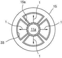
도15는 다른 실시 예에 따른 태양광 발전 유니트의 하우징의 구조를 개략적으로 예시한다.
도16은 다수의 태양광 발전 유니트에 의해 발전 시스템의 태양 발전 구조체를 개략적으로 도시한다.
도17은 도16에 도시된 태양 발전 구조체의 하부를 부분적으로 도시한다.
도18은 모범적 실시 예에 따른 태양 발전 시스템의 개략적 구성을 예시한다. 1 is a perspective view showing a concept of a power generation system by a single optical fiber and a plurality of solar panels surrounding it according to an exemplary embodiment.
Fig. 2 is a sectional view taken along line II in Fig. 1 showing the relationship between the optical fiber and the solar panel.
FIG. 3 is a perspective view for explaining the progress (emission) of light waves through the light exit window of the light exit region and the light wave entrance to the core of the optical fiber in the light guide region Ri.
Fig. 4 is a longitudinal sectional view of the optical fiber shown in Fig. 3;
Fig. 5 is a cross-sectional view of the optical fiber shown in Fig. 3;
6 illustrates an optical fiber having a spiral light output portion formed in a clad according to one embodiment.
7 schematically shows a solar power unit in the form of a square bar according to one embodiment.
Fig. 8 is a sectional view taken along line II-II in Fig. 7;
FIG. 9 shows the cross-sectional view of FIG. 8 in three dimensions.
10 shows a partial structure of a photovoltaic unit in which a plurality of optical fibers are installed inside a housing according to another embodiment.
FIG. 11 illustrates an optical fiber that can be applied to the photovoltaic power generation unit shown in FIG. 10.
Fig. 12 illustrates the light exit direction from the optical fiber in the space inside the housing.
13 is a three-dimensional view of the internal structure of a schematic housing of a photovoltaic unit according to another embodiment.
Fig. 14 is a sectional view taken along line III-III in Fig. 13;
15 schematically illustrates the structure of a housing of a photovoltaic unit according to another embodiment.
16 schematically shows a solar power structure of a power generation system by a plurality of solar power units.
FIG. 17 partially shows the lower portion of the solar power structure shown in FIG. 16.
18 illustrates a schematic configuration of a solar power system according to an exemplary embodiment.
이하, 첨부도면을 참조하여 본 발명 개념의 바람직한 실시예들을 상세히 설명하기로 한다. 그러나, 본 발명 개념의 실시예들은 여러 가지 다른 형태로 변형될 수 있으며, 본 발명 개념의 범위가 아래에서 상술하는 실시예들로 인해 한정 되어지는 것으로 해석되어져서는 안 된다. 본 발명 개념의 실시예들은 당 업계에서 평균적인 지식을 가진 자에게 본 발명 개념을 보다 완전하게 설명하기 위해서 제공 되어지는 것으로 해석되는 것이 바람직하다. 동일한 부호는 시종 동일한 요소를 의미한다. 나아가, 도면에서의 다양한 요소와 영역은 개략적으로 그려진 것이다. 따라서, 본 발명 개념은 첨부한 도면에 그려진 상대적인 크기나 간격에 의해 제한되어지지 않는다.Hereinafter, preferred embodiments of the inventive concept will be described in detail with reference to the accompanying drawings. However, embodiments of the inventive concept may be modified in various other forms, and the scope of the inventive concept should not be interpreted as being limited by the embodiments described below. It is preferred that the embodiments of the inventive concept be interpreted as being provided to more fully explain the inventive concept to a person skilled in the art. The same sign means the same element. Furthermore, various elements and areas in the drawings are schematically drawn. Therefore, the concept of the present invention is not limited by the relative size or spacing drawn in the accompanying drawings.
제1, 제2 등의 용어는 다양한 구성 요소들을 설명하는 데 사용될 수 있지만, 상기 구성 요소들은 상기 용어들에 의해 한정되지 않는다. 상기 용어들은 하나의 구성 요소를 다른 구성 요소로부터 구별하는 목적으로만 사용된다. 예를 들어, 본 발명 개념의 권리 범위를 벗어나지 않으면서 제 1 구성 요소는 제 2 구성 요소로 명명될 수 있고, 반대로 제 2 구성 요소는 제 1 구성 요소로 명명될 수 있다.Terms such as first and second may be used to describe various components, but the components are not limited by the terms. The terms are used only for the purpose of distinguishing one component from other components. For example, the first component may be referred to as a second component, and the second component may be referred to as a first component without departing from the scope of the inventive concept.
본 출원에서 사용한 용어는 단지 특정한 실시예들을 설명하기 위해 사용된 것으로서, 본 발명 개념을 한정하려는 의도가 아니다. 단수의 표현은 문맥상 명백하게 다르게 뜻하지 않는 한, 복수의 표현을 포함한다. 본 출원에서, “포함한다” 또는 “갖는다” 등의 표현은 명세서에 기재된 특징, 개수, 단계, 동작, 구성 요소, 부분품 또는 이들을 조합한 것이 존재함을 지정하려는 것이지, 하나 또는 그 이상의 다른 특징들이나 개수, 동작, 구성 요소, 부분품 또는 이들을 조합한 것들의 존재 또는 부가 가능성을 미리 배제하지 않는 것으로 이해되어야 한다.The terms used in this application are only used to describe specific embodiments and are not intended to limit the concept of the present invention. Singular expressions include plural expressions unless the context clearly indicates otherwise. In this application, the expression “comprises” or “haves” is intended to indicate that a feature, number, step, operation, component, part, or combination thereof described in the specification exists, or that one or more other features or It should be understood that the presence or addition possibilities of the number, operation, components, parts or combinations thereof are not excluded in advance.
달리 정의되지 않는 한, 여기에 사용되는 모든 용어들은 기술 용어와 과학 용어를 포함하여 본 발명 개념이 속하는 기술 분야에서 통상의 지식을 가진 자가 공통적으로 이해하고 있는 바와 동일한 의미를 지닌다. 또한, 통상적으로 사용되는, 사전에 정의된 바와 같은 용어들은 관련되는 기술의 맥락에서 이들이 의미하는 바와 일관되는 의미를 갖는 것으로 해석되어야 하며, 여기에 명시적으로 정의하지 않는 한 과도하게 형식적인 의미로 해석되어서는 아니 될 것임은 이해될 것이다.Unless otherwise defined, all terms used herein have the same meaning as commonly understood by those skilled in the art to which the inventive concept belongs, including technical terms and scientific terms. In addition, commonly used terms, as defined in the dictionary, should be interpreted as having meanings consistent with what they mean in the context of related technologies, and in excessively formal meanings unless explicitly defined herein. It will be understood that it should not be interpreted.
어떤 실시예가 달리 구현 가능한 경우에 특정한 공정 순서는 설명되는 순서와 다르게 수행될 수도 있다. 예를 들어, 연속하여 설명되는 두 공정이 실질적으로 동시에 수행될 수도 있고, 설명되는 순서와 반대의 순서로 수행될 수도 있다.When an embodiment can be implemented differently, a specific process order may be performed differently from the described order. For example, two processes described in succession may be performed substantially simultaneously, or may be performed in an order opposite to that described.
첨부 도면에 있어서, 예를 들면, 제조 기술 및/또는 공차에 따라, 도시된 형상의 변형들이 예상될 수 있다. 따라서, 본 발명의 실시예들은 본 명세서에 도시된 영역의 특정 형상에 제한된 것으로 해석되어서는 아니 되며, 예를 들면 제조 과정에서 초래되는 형상의 변화를 포함하여야 한다. 여기에 사용되는 모든 용어 "및/또는"은 언급된 구성 요소들의 각각 및 하나 이상의 모든 조합을 포함한다. 또한, 본 명세서에서 사용되는 용어 "기판"은 기판 그 자체, 또는 기판과 그 표면에 형성된 소정의 층 또는 막 등을 포함하는 적층 구조체를 의미할 수 있다. 또한, 본 명세서에서 "기판의 표면"이라 함은 기판 그 자체의 노출 표면, 또는 기판 위에 형성된 소정의 층 또는 막 등의 외측 표면을 의미할 수 있다. 또한 "상부" 나 "상"이라고 기재된 것은 접촉하여 바로 위에 있는 것뿐만 아니라 비접촉으로 위에 있는 것도 포함할 수 있다.In the accompanying drawings, for example, depending on manufacturing techniques and/or tolerances, deformations of the illustrated shapes can be expected. Therefore, the embodiments of the present invention should not be interpreted as being limited to a specific shape of a region shown in the present specification, but should include a change in shape resulting from, for example, a manufacturing process. All terms “and/or” as used herein include each and every combination of one or more of the components mentioned. In addition, the term "substrate" as used herein may mean a laminate structure including a substrate itself, or a predetermined layer or film formed on the substrate and its surface. In addition, in this specification, the term “surface of the substrate” may mean an exposed surface of the substrate itself, or an outer surface of a predetermined layer or film formed on the substrate. In addition, what is described as "upper" or "upper" may include not only that which is directly above in contact, but also that which is above in a non-contact manner.
이하에서 설명되는 모범적 실시 예들에 적용되는 발전부의 솔라 패널 또는 솔라셀은 특정 구조에 제한되지 않는다. 즉, 하나 또는 그 이상의 실시 예에 적용되는 솔라 패널은 광파에 의해 전기를 발생하는 어떠한 형태의 광전변환 장치 또는 광전 변환 소자로도 대체 가능하다. The solar panel or the solar cell of the power generation unit applied to the exemplary embodiments described below is not limited to a specific structure. That is, the solar panel applied to one or more embodiments can be replaced with any type of photoelectric conversion device or photoelectric conversion element that generates electricity by light waves.
바람직한 실시 예들에 따르면, 발전부는 굳은 재질의 기판을 포함하는 솔리드 솔라 패널 또는 가요성 기판을 포함하는 플렉서블 솔라 패널을 포함할 수 있다. 다른 실시 예에 따르면, 발전부는 유기 고분자 또는 무기 반도체 솔라셀을 포함할 수 있다. 또 다른 실시 예에 따르면, 발전부는 비정질 또는 다결정 실리콘계 솔라 패널을 포함할 수 있다. 하나 또는 그 이상의 실시 예에 따르면, 상기 발전부는 가요성 금속 또는 무기 필름 상의 기판 상에 형성되는 유기 고분자 또는 무기 화합물 광전변환물질을 포함할 수 있다. 하나 또는 그 이상의 실시 예에 따르면, 상기 발전부는 페로브스카이트 솔라 패널 또는 염료 감응형 솔라 패널을 포함할 수 있다.하나 또는 그 이상의 실시 예에 따르면, 상기 발전부는 상기 하우징의 내벽에 직접 형성되는 광전변환구조물을 포함할 수 있으며, 이하의 설명에서 언급되는 솔라 패널 또는 솔라셀은 위와 같은 특정 구조에 국한되지 않음은 물론이다.According to preferred embodiments, the power generation unit may include a solid solar panel including a rigid substrate or a flexible solar panel including a flexible substrate. According to another embodiment, the power generation unit may include an organic polymer or an inorganic semiconductor solar cell. According to another embodiment, the power generation unit may include an amorphous or polycrystalline silicon-based solar panel. According to one or more embodiments, the power generation unit may include an organic polymer or an inorganic compound photoelectric conversion material formed on a substrate on a flexible metal or inorganic film. According to one or more embodiments, the power generation unit may include a perovskite solar panel or a dye-sensitized solar panel. According to one or more embodiments, the power generation unit is directly formed on the inner wall of the housing. Of course, it may include a photoelectric conversion structure, and the solar panel or solar cell mentioned in the following description is not limited to the specific structure as described above.
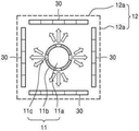
도1은 모범적 한 실시 예에 따라, 하나의 광 파이버와 이를 에워싸는 다수의 솔라 패널들에 의한 발전 시스템의 개념을 보여 주는 사시도이며, 도2는 광 파이버와 솔라 패널의 관계를 보이는 도1의 I-I 선 단면도이다.1 is a perspective view showing the concept of a power generation system by a single optical fiber and a plurality of solar panels surrounding it according to an exemplary embodiment, and FIG. 2 is a view showing the relationship between the optical fiber and the solar panel II of FIG. 1 It is a line section.
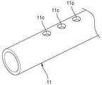
도1, 2를 참조하면, 광 파이버(11)의 출광 영역(Ro)의 외주면에 광파(1)가 통과하는 출광 윈도우(11c)가 다수 형성되어 있고, 광 파이버(11)의 주위에 다수 솔라 패널(30)에 의한 발전부가 배치된다. 여기에서 솔라 패널(30)에 의해 부분적으로 또는 전체적으로 에워싸인 광 파이버의 일 부분이 출광부 또는 출광 영역(Ro)에 해당하고, 광파(1)가 주입되는 부분은 광 안내부 또는 광 안내 영역(Ri)에 해당한다.Referring to FIGS. 1 and 2, a plurality of
광파(1)는 광 파이버(11)의 코어(11a)를 통해 광 안내영역(Ri)로 주입되며, 출광 영역(RO)에서 코어(11a)를 진행하던 광파(1)의 일부가 코어(11a)를 덮고 있는 클래드(11b)에 형성되는 출광 윈도우(11c)를 통과한다.The
상기 출광 영역(Ro)의 출광 윈도우(11c)는 클래드(11b)의 부분적 제거에 의해 형성되며, 그 바닥에 코어(11a)가 노출되어 있다. 본 실시예에서는 4방향으로 배치된 4매의 솔라 패널(30)에 대응하여, 상기 광 파이버(11)의 출광부(11c)는 방사상 4개의 방향으로 형성된다.The
상기 솔라 패널(30)들은 광 파이버(11)의 출광 윈도우(11c)로부터의 광파 진행경로 상에 배치된다. 솔라 패널(30)은 그 개수에 제한되지 않으며, 다른 실시 예에 따라 두 매 또는 세 매 또는 네 매, 나아가서는 그 이상이 마련되어 광 파이버(11)의 출광 영역이 부분적으로 또는 전체적으로 상기 솔라 패널(30)에 의해 에워싸일 수 있다. 또한 모범적 다른 실시 예에 따르면, 상기 솔라 패널(30)은 상기 광 파이버(11)를 에워싸는 다수의 벽체(12a)를 가지는 사각 기둥 또는 다각 기둥형상의 하우징(12)의 내부에 설치될 수 있다.The
상기 광 파이버(11)는 하우징(12) 또는 이 안쪽의 다수의 솔라 패널(30) 들에 의해 마련되는 내부 공간에 설치되어 모든 솔라 패널(30)들로 광파(1)를 공급한다.The
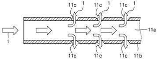
도3은 광 안내영역(Ri)에서 상기 광 파이버(11)의 코어(11a)로의 광파(1)의 입사 및 출광 영역(Ro)의 출광 윈도우(11c)를 통한 광파의 진행(방출)을 설명하는 사시도이며, 도4는 광 파이버(11)의 종단면도, 그리고 도5는 광 파이버(11)의 횡단면도이다.FIG. 3 illustrates the incidence (emission) of light waves through the
도3, 4, 5도를 참조하면, 광파(1)가 진행하는 코어(11a)가 클래드(11b)에 덮여 있다. 클래드(11b)는 계면 반사를 통해 광파(1)를 코어(11a)내에 가두어서 광파가 코어(11a) 내부를 진행하도록 안내 한다. 출광 영역에서 클래드(11b)에 형성되는 출광 윈도우(11c)의 하부 또는 바닥에는 코어(11a)의 표면이 노출되어 있고, 따라서 이 부분에는 코어(11a)를 진행하던 광파(1) 일부가 이를 통해 외부로 빠져 나온다.3, 4, and 5, the
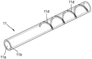
도6은 클래드에 형성되는 스파이럴 출광부(11d)를 가지는 광 파이버(11)를 예시한다. 상기 스파이럴형 출광부(11d)는 광 파이버(11)의 외주면을 돌아가면서 스파이럴형으로 형성되는 그루브(groove)에 의해 형성될 수 있다. 이 그루브는 광 파이버 외주면 전체에서 연속되게 형성되거나 또는 부분적으로 단절되어 크래드에 비연속적으로 형성될 수 있다. 그러나 다양한 실시 예들은 클래드에 형성되는 특정한 구조나 형태의 출광 윈도우에 의해 기술적으로 제한되지 않음은 당연하다.Fig. 6 illustrates an
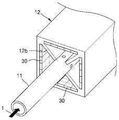
도7은 좀 더 구체화된 한 실시 예에 따른 사각 바(bar) 형태의 태양광 발전 유니트를 개략적으로 도시한다.7 schematically illustrates a photovoltaic unit in the form of a square bar according to one embodiment.
도7에 도시된 태양광 발전 유니트(10)는 광 파이버(11)의 출광 영역(Ro)이 내장되는 내부 공간을 형성하는 다수의 벽체(12a)를 가지는 하우징(12)을 포함한다. 상기 하우징(12)의 내부에는, 도1과 도2의 설명에서 언급 되었던 바와 같이 광 파이버(11)의 출광 영역(Ro)을 부분적으로 또는 전체적으로 에워싸는 하나 또는 그 이상의 솔라 패널(30)이 배치된다.The
상기 하우징(12)의 양단에는, 실링 부재 또는 앤드캡(13, 14)이 결합되어 있고, 일측 앤드캡(13)을 광 파이버(11)가 관통한다. 상기 앤드캡(13, 14)은 하우징(12)의 내부 공간은 외부와 격리되며, 진공 상태일 수 있다. 진공 상태의 하우징(12) 내부 공간은 습기나 이물질 등에 의해 광 산란 또는 흡수를 방지하여 발전을 위한 광이용 효율을 높인다.The sealing member or the end caps 13 and 14 are coupled to both ends of the
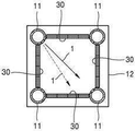
도8은 도7의 II-II 선 단면도이며, 도9는 도8의 단면도를 입체적으로 보인다.FIG. 8 is a sectional view taken along line II-II in FIG. 7, and FIG. 9 is a three-dimensional view of the sectional view in FIG.
도7, 8, 9에 도시된 바와 같이, 하우징(12)은 사각 단면을 가지는 사각 막대(bar)의 형태를 가지며, 그 중앙에 광 파이버(11)의 출광 영역이 위치한다. 그리고 하우징 내부의 네 귀퉁이로부터 그 내부 중심으로 향하는 대각선 방향의 리브(lib, 12a)가 소정 길이 연장하여 하우징 내부 중심에 마련되는 광 파이버(11)를 지지한다. 그리고, 하우징(12)의 내부의 4개의 벽체(12a)의 내면 각각에 솔라 패널(30)이 설치된다.7, 8, and 9, the
상기 솔라 패널(30)은 특정 물질이나 구조에 의해 한정되지 않으며, 별도의 기판에 형성되는 완성체의 상태로 상기 하우징(12)의 내벽에 설치될 수 있으며, 다른 실시 예에 따르면, 상기 하우징(12)의 내벽 자체에 광전변환물질 및 그 양측의 전극의 코팅에 의해 형성될 수 도 있다The
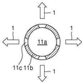
도10은 다른 실시 예에 따라 복수의 광 파이버가 하우징 내부에 설치된 태양광 발전 유니트의 부분적인 구조를 보이며, 도11은 도10에 도시된 태양광 발전 유니트에 적용될 수 있는 광 파이버를 예시하며, 그리고 도12는 하우징 내의 광 파이버로부터의 출광 방향을 예시한다.FIG. 10 shows a partial structure of a photovoltaic unit in which a plurality of optical fibers are installed inside a housing according to another embodiment, and FIG. 11 illustrates an optical fiber that can be applied to the photovoltaic unit shown in FIG. And Fig. 12 illustrates the light exit direction from the optical fiber in the housing.
도10을 참조하면, 사각 중공 봉상의 하우징(12)의 내벽에 솔라 패널(30)이 설치 또는 형성된다. 그리고, 하우징(12)의 내측의 4개의 모퉁이에는 광 파이버(11)가 설치된다. 이 구조에서는 도11에 도시된 바와 같이 한 방향으로만 광파가 출사되는 출광 윈도우(11c)가 형성되어 있는 광 파이버(11)가 적용된다. 이때에 도12에 도시된 바와 같이 광 파이버(11)는 출광 방향(화살표)이 하우징(12) 내부 공간을 향하도록 하고, 이때에 출광 방향을 내부 중심(실선 화살표) 또는 이에서 벗어나서 맞은편 두 솔라 패널 중 어느 하나를 향하도록(점선 화살표) 배향시킬수 있다.Referring to FIG. 10, a
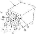
도13은 다른 실시 예에 따른 태양광 발전 유니트의 개략적 하우징 내부 구조를 입체적으로 보이며, 도14는 도13의 III-III 선 단면도이다. 13 is a three-dimensional view of the internal structure of a schematic housing of a photovoltaic unit according to another embodiment, and FIG. 14 is a sectional view taken along line III-III of FIG. 13.
도13과 14를 참조하면, 하우징(15)은 원형 또는 타원형 파이프 또는 튜브의 형태를 가지고 있으며, 그 내부 중심에 하우징(15)의 내벽으로부터 그 중심으로 방향으로 연장되는 다수의 리브(15a)에 의해 지지되는 광 파이버(11)가 위치하고, 하우징(15)의 그 내면에 솔라 패널(33)이 부착 또는 형성되어 있다. 상기 솔라 패널(30)은 상기 하우징(15) 내벽 자체에 광전 변환물질 및 전극을 포함하는 적층 구조체로서 내벽에 직접 형성될 수 도 있으며, 다른 실시 예에 따르면 가요성 필름을 베이스로 하는 가요성 솔라 패널으로 대체될 수 있다. 이러한 실시 예에서는 광 파이버(11)로부터의 솔라 패널 부분별 광파의 진행거리의 차가 전술한 실시 예의 사각형 하우징의 태양광 발전 유니트에서의 진행 거리의 차에 비해 적다.13 and 14, the
도15는 다른 실시 예에 따른 태양광 발전 유니트의 하우징의 구조를 개략적으로 예시한다. 본 실시 예에서의 하우징(16)은 중공 원기둥 형상을 가지며, 그 내부에는 파상형으로 주름진 형태의 내벽(16a)이 형성되어 있다. 따라서 하우징의 단면에서 하우징 내부 공간은 주름진 파상형 또는 별 형상을 가진다. 이러한 구조에 따르면, 따라서 파상형 내벽(16a)은 크게 확장된 면적을 가지게 된다.15 schematically illustrates the structure of a housing of a photovoltaic unit according to another embodiment. The
이러한 주름진 내벽(16a)에는 태양발전을 위한 광전 변환 구조물이 적층형성될 수있으며, 그 내부에는 전술한 여러 형태의 광 파이버가 하나 또는 그 이상 설치될 수 있다.A photoelectric conversion structure for solar power generation may be stacked on the corrugated
또한 주름 내벽의 돌출부는 내부 공간 중심영역에 위치하는 광 파이버를 지지할 수 있다.In addition, the protrusion of the inner wall of the corrugation can support the optical fiber located in the central region of the inner space.
도16은 다수의 태양광 발전 유니트에 의해 발전 시스템의 태양 발전 구조체를 개략적으로 도시하며, 도17은 도16에 도시된 태양 발전 구조체의 하부를 부분적으로 도시한다.FIG. 16 schematically shows a solar power structure of a power generation system by a plurality of photovoltaic units, and FIG. 17 partially shows a lower portion of the solar power structure shown in FIG.
도16과 도17을 참조하면, 일 방향(도면에서 상하)으로 정렬된 태양광 발전 유니트(10)가 하나의 평면상에 2차원적으로 다수 밀집 배열되어 있다. 태양광 발전 유니트(10)는 사각 튜브형태의 하우징(12)과 하우징(12)의 내부에 그 일측의 출광 영역(Ro)이 위치하는 광 파이버를 구비한다. 이러한 태양광 발전 유니트(10)는 두 개의 방향으로 다수 밀집되어 큰 규모의 태양 발전 구조체(40)를 구현한다.16 and 17, the photovoltaic
도16에 도시된 태양 발전 구조체에서 그 상부에 마련된 무수한 광 파이버(11)의 광 안내영역(Ri)들은 하나 또는 복수의 묶음으로 다발(번들)화하며, 각 번들 마다 태양광을 광학 시스템에 의해 수렴 시킨다.In the solar power generation structure shown in FIG. 16, the light guide regions Ri of the myriad of
도18은 도16, 17에 도시된 태양 발전 구조체가 적용되는 발전 시스템의 개략적 구성도이다.18 is a schematic configuration diagram of a power generation system to which the solar power generation structures shown in FIGS. 16 and 17 are applied.
도18에 도시된 바와 같이, 도16에 도시된 태양 발전 구조체(40)의 외부 광 파이버, 즉 광 파이버의 광안내부(Ri)의 선단부를 하나로 묶어서 다수 광 파이버의 단면(facet)의 집적에 의한 하나의 공통된 광입사면 또는 광입사부(41)를 형성하고, 여기에 태양광을 광입사부(41)에 수렴 시키는 광학 시스템(50)을 설치한다.As shown in FIG. 18, the outer optical fiber of the solar
상기와 같은 모범적 실시 예에서, 태양광 발전 유니트의 솔파 패널은 잘 알려진 페로브스카이트 솔파 패널 또는 셀을 적용할 수 있다. 페로브스카이트 솔라 패널 또는 솔라 셀은 페로브스카이트 구조 화합물을 포함한다.In the exemplary embodiment as described above, the solar panel of the solar power unit may employ a well-known perovskite solar panel or cell. The perovskite solar panel or solar cell contains a perovskite structural compound.
본 개시에서 특정한 실시 예에 관련하여 도시하고 설명 하였지만, 이하의 특허청구범위에 의해 제공되는 본 발명의 정신이나 분야를 벗어나지 않는 한도 내에서 본 발명이 다양하게 개량 및 변화될 수 있다는 것을 당 업계에서 통상의 지식을 가진 자는 용이하게 알 수 있음을 밝혀 두고자 한다.Although shown and described in relation to a specific embodiment in the present disclosure, it is understood in the art that the present invention can be variously improved and changed within the limits that do not depart from the spirit or field of the present invention provided by the following claims. It is intended to be revealed that a person with ordinary knowledge can easily know.
Claims (16)
상기 광 섬유의 일 측 영역에 마련되는 것으로, 상기 코어를 진행하는 광을 광섬유 외부로 굴절시키는 하나 또는 그 이상의 출광 윈도우가, 상기 광이 진행하는 방향을 따라 상기 코어의 둘레를 돌아가며 에워싸는 형태로 형성되어 있는 출광 영역(light output region); 그리고
상기 코어의 일측으로부터 입사된 광을 상기 출광 영역으로 안내하는 광 안내영역(light guide region); 포함하는 광 수송 매체.An optical fiber including a core having a predetermined length through which light travels;
It is provided in one region of the optical fiber, and one or more light exit windows that refract the light passing through the core to the outside of the optical fiber are formed in a form surrounding the core around the light traveling direction. A light output region; And
A light guide region guiding light incident from one side of the core to the light exit region; Optical transport medium containing.
상기 광섬유는 상기 코어를 덮는 크래드(clad)를 포함하며, 상기 출광 윈도우는 상기 크래드에 형성되는, 광 수송 매체.According to claim 1,
The optical fiber includes a clad covering the core, and the light exit window is formed in the clad.
상기 출광 윈도우는 상기 크래드에 형성되는 그루브에 의해 마련되는, 광 수송 매체.According to claim 2,
The light exit window is provided by a groove formed in the clad, the light transport medium.
상기 그루브는 연속적 또는 국부적으로 단절된 불연속적 스파이럴 또는 나선의 형태를 가지는, 광 수송 매체.According to claim 3,
The groove has a continuous spiral or discontinuous discontinuous spiral or helix shape.
상기 출광 윈도우는 상기 코어를 둘러싸는 스파이럴 형태를 가지는, 광 수송 매체.According to claim 1,
The light exit window has a spiral shape surrounding the core, the light transport medium.
상기 광 수송 매체가 위치하는 내부 공간을 가지는 튜브 타입(tube type)의 하우징(housing); 그리고
상기 하우징 내부의 적어도 일 측에 마련되어 상기 광 파이버의 출광 영역으로부터 입사하는 광파에 의해 발전을 행하는 솔라 패널을 포함하는 발전부(power generation part); 를 포함하는 태양광 발전 유니트.The optical transport medium according to any one of claims 1 to 5;
A tube type housing having an inner space in which the light transport medium is located; And
A power generation part provided on at least one side of the inside of the housing and including a solar panel for generating power by light waves incident from an exit region of the optical fiber; Solar power generation unit comprising a.
상기 하우징의 내부 공간을 에워싸는 상기 튜브 형태의 하우징의 내부 공간은 파상형으로 주름진 형태의 내벽을 가지며,
상기 내벽에 솔라 패널이 형성되어 있는, 태양광 발전 유니트The method of claim 6,
The inner space of the tube-shaped housing surrounding the inner space of the housing has a wavy corrugated inner wall,
Solar power generation unit, wherein a solar panel is formed on the inner wall
상기 하우징의 내벽에는 광 수송 매체를 지지하는 리브가 형성되어 있고,
상기 하우징의 내벽과 리브에 솔라 패널이 형성되어 있는, 태양광 발전 유니트The method of claim 6,
The inner wall of the housing is formed with a rib for supporting the light transport medium,
Solar power generation unit, wherein a solar panel is formed on the inner wall and rib of the housing
상기 하우징은 파상형으로 주름진 형태의 내벽을 가지며,
상기 내벽에는 상기 솔라 패널이 형성되어 있고, 상기 광 수송 매체는 상기 내벽으부터 이격되어 있는, 태양광 발전 유니트The method of claim 6,
The housing has a wavy corrugated inner wall,
The solar panel is formed on the inner wall, and the light transport medium is spaced apart from the inner wall.
상기 하우징의 내부 공간은 앤드캡에 의해 외부와 격리되어 기밀(air tightly) 또는 진공 상태를 유지하는, 태양광 발전 유니트.The method of claim 6,
The inner space of the housing is isolated from the outside by an end cap to maintain an air tightly or vacuum state.
상기 광 파이버의 광 안내영역에 태양광을 수렴(converge)하여 상기 태양 발전 유닛으로 광파를 공급하는 광학 구조체;를 포함하는 태양광 발전 시스템.The solar power generation unit according to claim 6; And
And an optical structure that converges sunlight to a light guide region of the optical fiber to supply light waves to the solar power unit.
상기 하우징은 사각형, 다각형, 원형, 타원형 중의 어느 하나의 단면형상을 가지는, 태양광 발전 시스템.The method of claim 11,
The housing has a cross-sectional shape of any one of rectangular, polygonal, circular, and oval, solar power system.
상기 하우징은 상기 내부 공간을 형성하는 다수의 벽체을 가지며,
상기 하우징의 내부 공간의 중앙 영역에 상기 광 파이버가 위치하고,
상기 다수 벽체 중 적어도 적어도 하나에 상기 솔라 패널이 형성 또는 설치되어 있는, 태양광 발전 시스템.The method of claim 11,
The housing has a number of walls forming the interior space,
The optical fiber is located in a central region of the inner space of the housing,
The solar panel is formed or installed on at least one of the plurality of walls, a solar power system.
상기 하우징의 벽체에는 상기 내부 공간에 위치하는 광 파이버를 지지하는 리브(lib)가 하나 또는 그 이상 돌출 형성되어 있는, 태양광 발전 시스템.The method of claim 12,
The wall of the housing is formed with one or more protruding ribs (lib) for supporting the optical fibers located in the interior space, a solar power system.
상기 하우징은 상기 광 파이버를 에워싸는 다수의 벽체을 가지며,
상기 내부 공간에서 상기 벽체들 사이에 다수의 코너 중 적어도 어느 하나에 상기 광 파이버가 위치하고,
상기 다수 벽체 중 적어도 하나에 상기 광 파이버로부터의 광이 입사하는솔라 패널이 형성 또는 설치되어 있는, 태양광 발전 시스템.The method of claim 12,
The housing has a number of walls surrounding the optical fiber,
The optical fiber is located in at least one of a plurality of corners between the walls in the interior space,
A photovoltaic power generation system in which a solar panel in which light from the optical fiber is incident is formed or installed on at least one of the plurality of walls.
상기 하우징의 내부 공간은 앤드캡에 의해 외부와 격리되어 기밀(air tightly) 또는 진공 상태를 유지하는, 태양광 발전 시스템.The method of claim 12,
The inner space of the housing is isolated from the outside by an end cap to maintain an air tightly or vacuum state, a solar power system.
Priority Applications (1)
| Application Number | Priority Date | Filing Date | Title |
|---|---|---|---|
| KR1020210105380A KR20210102139A (en) | 2018-07-02 | 2021-08-10 | light transporting media and solar power generation system adopting the media |
Applications Claiming Priority (2)
| Application Number | Priority Date | Filing Date | Title |
|---|---|---|---|
| US201862692971P | 2018-07-02 | 2018-07-02 | |
| US62/692,971 | 2018-07-02 |
Related Parent Applications (1)
| Application Number | Title | Priority Date | Filing Date |
|---|---|---|---|
| KR1020190010070A Division KR20200003705A (en) | 2018-07-02 | 2019-01-25 | solar power generation unit and system |
Related Child Applications (1)
| Application Number | Title | Priority Date | Filing Date |
|---|---|---|---|
| KR1020210105380A Division KR20210102139A (en) | 2018-07-02 | 2021-08-10 | light transporting media and solar power generation system adopting the media |
Publications (1)
| Publication Number | Publication Date |
|---|---|
| KR20200083408A true KR20200083408A (en) | 2020-07-08 |
Family
ID=69158573
Family Applications (5)
| Application Number | Title | Priority Date | Filing Date |
|---|---|---|---|
| KR1020190010070A KR20200003705A (en) | 2018-07-02 | 2019-01-25 | solar power generation unit and system |
| KR1020200078816A KR20200083408A (en) | 2018-07-02 | 2020-06-26 | light transporting media and solar power generation system adopting the media |
| KR1020200078815A KR102269086B1 (en) | 2018-07-02 | 2020-06-26 | basr-type solar power generation unit and system |
| KR1020210074162A KR20210071909A (en) | 2018-07-02 | 2021-06-08 | bar-type solar power generation unit and system |
| KR1020210105380A KR20210102139A (en) | 2018-07-02 | 2021-08-10 | light transporting media and solar power generation system adopting the media |
Family Applications Before (1)
| Application Number | Title | Priority Date | Filing Date |
|---|---|---|---|
| KR1020190010070A KR20200003705A (en) | 2018-07-02 | 2019-01-25 | solar power generation unit and system |
Family Applications After (3)
| Application Number | Title | Priority Date | Filing Date |
|---|---|---|---|
| KR1020200078815A KR102269086B1 (en) | 2018-07-02 | 2020-06-26 | basr-type solar power generation unit and system |
| KR1020210074162A KR20210071909A (en) | 2018-07-02 | 2021-06-08 | bar-type solar power generation unit and system |
| KR1020210105380A KR20210102139A (en) | 2018-07-02 | 2021-08-10 | light transporting media and solar power generation system adopting the media |
Country Status (1)
| Country | Link |
|---|---|
| KR (5) | KR20200003705A (en) |
Family Cites Families (4)
| Publication number | Priority date | Publication date | Assignee | Title |
|---|---|---|---|---|
| TW201034212A (en) * | 2009-03-13 | 2010-09-16 | guo-hong Shen | Thin-film solar cell structure |
| JP5841436B2 (en) * | 2012-01-23 | 2016-01-13 | 株式会社トヨタ車体研究所 | Solar power system |
| JP2017127040A (en) * | 2016-01-11 | 2017-07-20 | 国立大学法人名古屋大学 | Photovoltaic power generator |
| WO2017185188A1 (en) * | 2016-04-29 | 2017-11-02 | Solar Earth Technologies Ltd. | Photovoltaic power generation apparatus |
-
2019
- 2019-01-25 KR KR1020190010070A patent/KR20200003705A/en active Application Filing
-
2020
- 2020-06-26 KR KR1020200078816A patent/KR20200083408A/en active Application Filing
- 2020-06-26 KR KR1020200078815A patent/KR102269086B1/en active IP Right Grant
-
2021
- 2021-06-08 KR KR1020210074162A patent/KR20210071909A/en not_active IP Right Cessation
- 2021-08-10 KR KR1020210105380A patent/KR20210102139A/en not_active IP Right Cessation
Also Published As
| Publication number | Publication date |
|---|---|
| KR102269086B1 (en) | 2021-06-24 |
| KR20210102139A (en) | 2021-08-19 |
| KR20210071909A (en) | 2021-06-16 |
| KR20200083956A (en) | 2020-07-09 |
| KR20200003705A (en) | 2020-01-10 |
Similar Documents
| Publication | Publication Date | Title |
|---|---|---|
| JP6960963B2 (en) | Photovoltaic unit and its system | |
| JP6980032B2 (en) | Photovoltaic power generation unit using optical fiber and power generation system using it | |
| JP6416333B2 (en) | Solar cell module | |
| JP5399523B2 (en) | Smart solar concentrator depending on incident angle, method for manufacturing solar concentrator, and window system | |
| KR101324869B1 (en) | High efficiency solar power generator of stack type | |
| KR20200083408A (en) | light transporting media and solar power generation system adopting the media | |
| KR102511072B1 (en) | solar power generation unit and system | |
| US20210286126A1 (en) | Light transmitting fibered medium | |
| KR102469769B1 (en) | Fiber-type Solar generator and solar power generation system using the generator | |
| KR101172173B1 (en) | Solar cell apparatus |
Legal Events
| Date | Code | Title | Description |
|---|---|---|---|
| A107 | Divisional application of patent | ||
| E902 | Notification of reason for refusal | ||
| AMND | Amendment | ||
| E601 | Decision to refuse application | ||
| AMND | Amendment | ||
| X601 | Decision of rejection after re-examination | ||
| A107 | Divisional application of patent |