KR20200082458A - Redox flow battery - Google Patents
Redox flow battery Download PDFInfo
- Publication number
- KR20200082458A KR20200082458A KR1020180173065A KR20180173065A KR20200082458A KR 20200082458 A KR20200082458 A KR 20200082458A KR 1020180173065 A KR1020180173065 A KR 1020180173065A KR 20180173065 A KR20180173065 A KR 20180173065A KR 20200082458 A KR20200082458 A KR 20200082458A
- Authority
- KR
- South Korea
- Prior art keywords
- electrolyte
- storage tank
- redox flow
- distributor
- flow battery
- Prior art date
Links
Images


Classifications
-
- H—ELECTRICITY
- H01—ELECTRIC ELEMENTS
- H01M—PROCESSES OR MEANS, e.g. BATTERIES, FOR THE DIRECT CONVERSION OF CHEMICAL ENERGY INTO ELECTRICAL ENERGY
- H01M8/00—Fuel cells; Manufacture thereof
- H01M8/18—Regenerative fuel cells, e.g. redox flow batteries or secondary fuel cells
- H01M8/184—Regeneration by electrochemical means
- H01M8/188—Regeneration by electrochemical means by recharging of redox couples containing fluids; Redox flow type batteries
-
- H—ELECTRICITY
- H01—ELECTRIC ELEMENTS
- H01M—PROCESSES OR MEANS, e.g. BATTERIES, FOR THE DIRECT CONVERSION OF CHEMICAL ENERGY INTO ELECTRICAL ENERGY
- H01M8/00—Fuel cells; Manufacture thereof
- H01M8/04—Auxiliary arrangements, e.g. for control of pressure or for circulation of fluids
- H01M8/04082—Arrangements for control of reactant parameters, e.g. pressure or concentration
- H01M8/04186—Arrangements for control of reactant parameters, e.g. pressure or concentration of liquid-charged or electrolyte-charged reactants
-
- H—ELECTRICITY
- H01—ELECTRIC ELEMENTS
- H01M—PROCESSES OR MEANS, e.g. BATTERIES, FOR THE DIRECT CONVERSION OF CHEMICAL ENERGY INTO ELECTRICAL ENERGY
- H01M8/00—Fuel cells; Manufacture thereof
- H01M8/04—Auxiliary arrangements, e.g. for control of pressure or for circulation of fluids
- H01M8/04082—Arrangements for control of reactant parameters, e.g. pressure or concentration
- H01M8/04201—Reactant storage and supply, e.g. means for feeding, pipes
-
- H—ELECTRICITY
- H01—ELECTRIC ELEMENTS
- H01M—PROCESSES OR MEANS, e.g. BATTERIES, FOR THE DIRECT CONVERSION OF CHEMICAL ENERGY INTO ELECTRICAL ENERGY
- H01M8/00—Fuel cells; Manufacture thereof
- H01M8/04—Auxiliary arrangements, e.g. for control of pressure or for circulation of fluids
- H01M8/04276—Arrangements for managing the electrolyte stream, e.g. heat exchange
-
- Y—GENERAL TAGGING OF NEW TECHNOLOGICAL DEVELOPMENTS; GENERAL TAGGING OF CROSS-SECTIONAL TECHNOLOGIES SPANNING OVER SEVERAL SECTIONS OF THE IPC; TECHNICAL SUBJECTS COVERED BY FORMER USPC CROSS-REFERENCE ART COLLECTIONS [XRACs] AND DIGESTS
- Y02—TECHNOLOGIES OR APPLICATIONS FOR MITIGATION OR ADAPTATION AGAINST CLIMATE CHANGE
- Y02E—REDUCTION OF GREENHOUSE GAS [GHG] EMISSIONS, RELATED TO ENERGY GENERATION, TRANSMISSION OR DISTRIBUTION
- Y02E60/00—Enabling technologies; Technologies with a potential or indirect contribution to GHG emissions mitigation
- Y02E60/30—Hydrogen technology
- Y02E60/50—Fuel cells
Landscapes
- Life Sciences & Earth Sciences (AREA)
- Engineering & Computer Science (AREA)
- Manufacturing & Machinery (AREA)
- Sustainable Development (AREA)
- Sustainable Energy (AREA)
- Chemical & Material Sciences (AREA)
- Chemical Kinetics & Catalysis (AREA)
- Electrochemistry (AREA)
- General Chemical & Material Sciences (AREA)
- Fuel Cell (AREA)
Abstract
Description
본 발명은 레독스 흐름전지에 관한 것으로, 특히 충전 및 방전시 물리적, 전기적 성질이 달라진 전해액이 균일하게 섞일 수 있도록 한 레독스 흐름전지에 관한 것이다. The present invention relates to a redox flow battery, and more particularly, to a redox flow battery that allows the electrolyte solution having different physical and electrical properties to be uniformly mixed during charging and discharging.
최근 지구 온난화의 주요 원인인 온실가스 배출을 억제하기 위한 방법으로, 태양광 에너지나 풍력 에너지 같은 신재생에너지가 각광받고 있다. 이들의 실용화 보급을 위해 많은 연구가 진행되고 있다. 그러나 신재생에너지는 입지 환경이나 자연조건에 의해 크게 영향을 받으며, 더욱이 신재생에너지는 출력 변동이 심하기 때문에 에너지를 연속적으로 고르게 공급할 수 없다는 단점이 있다. Recently, as a method for suppressing greenhouse gas emission, which is a major cause of global warming, new and renewable energy such as solar energy or wind energy has been spotlighted. A lot of research has been conducted to promote their practical use. However, new and renewable energy is greatly affected by the location environment or natural conditions, and furthermore, since new and renewable energy has a large output fluctuation, it cannot be continuously supplied with energy.
따라서 신재생에너지를 가정용이나 상업용으로 사용하기 위해서는 출력이 높을 때 에너지를 저장하고 출력이 낮을 때 저장된 에너지를 사용할 수 있는 시스템을 도입하여 사용하고 있다. Therefore, in order to use renewable energy for home or commercial use, a system that stores energy when the output is high and uses the stored energy when the output is low is used.
이러한 에너지 저장 시스템으로는 대용량 이차전지가 사용된다. 예컨대, 대규모 태양광발전 및 풍력발전 단지에는 대용량 이차전지 저장시스템이 도입되고 있다. 대용량의 전력저장을 위한 이차전지로는 납축전지, 황화나트륨(NaS) 전지, 리튬전지, 또는 레독스 흐름전지(RFB: Redox flow battery) 등이 있다.A large capacity secondary battery is used as the energy storage system. For example, large-capacity photovoltaic and wind farms have been introduced with large-capacity secondary battery storage systems. Secondary batteries for storing large amounts of power include lead acid batteries, sodium sulfide (NaS) batteries, lithium batteries, or redox flow batteries (RFBs).
상기 레독스 흐름전지는 상온에서 동작 가능하며, 용량과 출력을 각기 독립적으로 설계할 수 있으므로 최근 대용량 이차전지로 많은 연구가 진행되고 있다. 레독스 흐름전지는 연료전지와 유사하게 분리막(멤브레인), 전극 및 분리판(Bipolar plate)이 직렬로 배치되어 구성됨으로써, 전기 에너지의 충방전이 가능한 이차전지(Secondary battery)의 기능을 가진다. The redox flow battery is capable of operating at room temperature, and since capacity and output can be independently designed, many studies have been conducted on large-capacity secondary batteries. The redox flow battery has a function of a secondary battery capable of charging and discharging electric energy by arranging a separator (membrane), an electrode, and a bipolar plate in series, similar to a fuel cell.
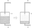
도1에 도시된 바와 같이, 레독스 흐름전지는 분리막의 양측에 양극 및 음극이 배치된 전지셀(1)이 마련되고, 상기 양극 및 음극으로 전해액을 공급하는 양극 전해액저장탱크(2)와 음극 전해액저장탱크(3)가 각각 마련된다. 상기 전해액(electrolyte)은 펌프(4)에 의해 제공되는 압력에 의해 전해액저장탱크(2,3), 공급유로(5), 전지셀(1), 및 회수유로(6)를 순차적으로 거치면서 반복적으로 순환한다. 상기 전해액은 상기 전지셀(1) 내에서 이온 교환이 이루어지고, 이 과정에서 전자의 이동이 발생하여 충방전이 이루어진다. 이와 같은 레독스 흐름전지는 기존 이차전지에 비하여 수명이 길고, kW 내지 MW 급의 중대형 시스템으로 제작할 수 있기 때문에 EES(Energy storage system)으로 적합하다.As shown in Figure 1, the redox flow battery is provided with a
그러나, 도1과 같은 종래의 레독스 흐름전지는, 충전 및 방전 시 전해액의 물리적 또는 화학적 성질이 달라져서 쉽게 혼합되지 않는 문제를 발생시킨다. However, in the conventional redox flow battery as shown in FIG. 1, the physical or chemical properties of the electrolytic solution are changed during charging and discharging, which causes problems that are not easily mixed.
구체적으로 도2는 충전된 전해액이 방전된 전해액보다 밀도가 높은 레독스 흐름전지에서, 레독스 흐름전지가 방전할 때, 양극 전해액저장탱크(2)에서의 전해액의 분포를 나타낸 것이다. 도2에 도시된 바와 같이, 전지셀(1)에서 방전되어 밀도가 낮아진 전해액이 회수유로(6)를 통해 양극 전해액저장탱크(2)로 들어오면, 양극 전해액저장탱크(2)에 저장되어 있는 충전된 전해액 위에 상기 밀도가 낮아진 전해액이 쌓이고, 공급유로(5)를 통하여는 밀도가 높은 충전된 전해액이 순착적으로 전지셀(1)로 공급된다. Specifically, FIG. 2 shows the distribution of the electrolyte in the anode
반면에, 도3은, 도2와 같이 충전된 전해액이 방전된 전해액보다 밀도가 높은 레독스 흐름전지에서, 레독스 흐름전지가 충전할 때, 양극 전해액저장탱크(2)에서의 전해액의 분포를 나타낸다. 도3에 도시된 바와 같이, 전지셀(1)에서 충전되어 밀도가 높아진 전해액이 방전된 전해액을 저장하고 있는 양극 전해액저장탱크(2)로 유입되면, 상대적으로 밀도가 높은 충전된 전해액은 양극 전해액저장탱크(2)의 하부로 내려간다.On the other hand, FIG. 3 shows the distribution of the electrolyte in the anode
밀도가 높은 전해액이 양극 전해액저장탱크(2)의 중심부에만 집중되고, 중심부에서 벗어난 부분의 전해액은 상대적으로 충전되지 않은 상태의 전해액으로 채워지게 되므로, 레독스 흐름전지 본래의 에너지 용량을 충분히 활용할 수 없는 문제가 있다. Since the high-density electrolyte is concentrated only in the center of the anode electrolyte storage tank (2), and the part of the electrolyte away from the center is filled with the electrolyte in a relatively uncharged state, it is possible to fully utilize the original energy capacity of the redox flow battery. There is no problem.
또한, 밀도가 높은 전해액이 양극 전해액저장탱크(2)의 중심부 하측으로 유동하여 충전을 위해 다시 전지셀(1)로 이동하는 경우, 상기 전지셀(1)은 유입된 전해액이 이미 충전된 상태이므로 충전을 위한 이온 교환에 악영향을 줄 수 있다.In addition, when the high-density electrolyte flows to the bottom of the center of the positive electrode
따라서, 충전 및 방전시 전지셀로부터 전해액탱크로 유입된 전해액이 균일하게 혼합될 수 있도록 하는 것이 중요하다.Therefore, it is important to ensure that the electrolyte flowing from the battery cell to the electrolyte tank during charging and discharging is uniformly mixed.
본 발명은 상술한 바와 같은 문제점을 개선하기 위해 안출된 것으로, 충전 및 방전시 물리적, 전기적 성질이 달라진 전해액이 균일하게 섞일 수 있도록 한 레독스 흐름전지를 제공함을 그 목적으로 한다. The present invention has been devised to improve the problems as described above, and it is an object of the present invention to provide a redox flow battery capable of uniformly mixing electrolytes having different physical and electrical properties during charging and discharging.
본 발명에 따른 레독스 흐름전지는, 양극 및 음극이 마련된 전지셀; 상기 양극 및 상기 음극에 전해액을 공급하는 전해액저장탱크; 상기 전해액이 상기 전해액저장탱크로부터 상기 전지셀로 공급되도록, 상기 전해액저장탱크과 상기 전지셀을 연결하는 공급유로; 상기 전해액이 상기 전지셀로부터 상기 전해액저장탱크로 회수되도록, 상기 전지셀과 상기 전해액저장탱크를 연결하는 회기유로; 상기 전해액저장탱크와 상기 전지셀 사이에서 상기 전해액을 순환시키는 압력을 제공하는 압력제공부; 상기 전해액저장탱크로 들어오는 상기 전해액을 분산시키는 분사공이 형성된 전해액분배기;를 포함하는 것이 바람직하다. Redox flow battery according to the present invention, a battery cell provided with an anode and a cathode; An electrolyte storage tank that supplies electrolyte to the anode and the cathode; A supply passage connecting the electrolyte storage tank and the battery cell such that the electrolyte is supplied from the electrolyte storage tank to the battery cell; A return passage connecting the battery cell and the electrolyte storage tank so that the electrolyte is recovered from the battery cell to the electrolyte storage tank; A pressure providing unit that provides a pressure for circulating the electrolyte between the electrolyte storage tank and the battery cell; It is preferable to include; an electrolytic solution distributor having a spray hole for dispersing the electrolytic solution entering the electrolyte storage tank.
또한, 상기 분사공의 직경은 상기 회기유로의 직경보다 작은 것이 바람직하다. In addition, it is preferable that the diameter of the injection hole is smaller than the diameter of the return passage.
또한, 상기 전해액분배기는 상기 전해액저장탱크의 상측에 마련되고, 상기 전해액은 상기 전해액분배기의 분사공을 통해 상측에서 하측으로 분사되는 것이 바람직하다. In addition, the electrolyte distributor is preferably provided on the upper side of the electrolyte storage tank, the electrolyte is preferably injected from the upper side to the lower side through the injection hole of the electrolyte distributor.
또한, 상기 전해액분배기는 판형으로 형성되고, 상기 분사공은 일정 간격으로 이격되어 형성된 것이 바람직하다. In addition, the electrolyte dispenser is formed in a plate shape, it is preferable that the injection hole is formed spaced apart at regular intervals.
또한, 상기 전해액분배기는 상기 전해액저장탱크의 하측에 마련되고, 상기 전해액은 상기 전해액분배기의 분사공을 통해 하측에서 상측으로 분사되는 것이 바람직하다. In addition, the electrolyte distributor is preferably provided on the lower side of the electrolyte storage tank, the electrolyte is preferably injected from the lower side to the upper side through the injection hole of the electrolyte distributor.
또한, 상기 전해액분배기는 상하 방향으로 서로 이격되어 복수 개 마련된 것이 바람직하다. In addition, it is preferable that the electrolyte distributors are provided in a plurality of spaced apart from each other in the vertical direction.
또한, 상기 전해액분배기는 판형으로 형성되고, 상기 분사공은 일정 간격으로 이격되어 형성된 것이 바람직하다. In addition, the electrolyte dispenser is formed in a plate shape, it is preferable that the injection hole is formed spaced apart at regular intervals.
또한, 상기 전해액분배기는 상기 회기유로에 대하여 회전하는 것이 바람직하다. In addition, it is preferable that the electrolytic solution distributor rotates with respect to the return passage.
또한, 상기 전해액분배기는 수평바를 포함하고, 상기 수평바의 중심에 상기 회기유로의 단부가 결합되며, 상기 수평바의 중심을 기준으로 좌측에 배치되는 좌측부에 형성된 상기 분사공에 의한 상기 전해액의 분사방향과, 우측에 배치되는 우측부에 형성된 상기 분사공에 의한 상기 전해액의 분사방향은 서로 반대인 것이 바람직하다. In addition, the electrolyte dispenser includes a horizontal bar, the end of the recirculation flow path is coupled to the center of the horizontal bar, and the injection of the electrolyte by the spray hole formed in the left portion disposed on the left side based on the center of the horizontal bar. It is preferable that the direction and the injection direction of the electrolyte solution by the injection holes formed on the right side disposed on the right side are opposite to each other.
또한, 상기 전해액분배기로부터 상기 분사공을 통해서 분사되는 상기 전해액의 분사방향은 상기 전해액분배기가 놓이는 가상의 평면과 소정의 각도를 갖는 것이 바람직하다. In addition, it is preferable that the injection direction of the electrolyte injected from the electrolyte distributor through the injection hole has a predetermined angle with a virtual plane on which the electrolyte distributor is placed.
또한, 상기 전해액분배기는 다공성 소재를 포함하며, 상기 분사공은 상기 다공성 소재에 형성된 구멍인 것이 바람직하다. In addition, the electrolyte dispenser includes a porous material, and it is preferable that the injection hole is a hole formed in the porous material.
또한, 상기 다공성 소재는 펠트, 직물, 또는 다공성폼인 것이 바람직하다. In addition, the porous material is preferably a felt, a fabric, or a porous foam.
또한, 상기 전해액분배기(60)는, 상기 회기유로(40)에 연결되어 나선상으로 회전하면서 연장되며, 상기 분사공(61)은 상기 전해액저장탱크(20)의 중심측을 향하여 상기 전해액을 분사되도록 형성된 것이 바람직하다. In addition, the
또한, 상기 전해액분배기(60)는, 상기 전해액저장탱크(20)의 내측에 소정의 간격을 갖도록 배치되며 내통부재(70)와, 상기 내통부재(70)에 마련된 복수의 분사공(71), 및 상기 내통부재와 상기 전해액저장탱크(20)가 서로 이격되어 형성되는 분배유로(72)를 포함하는 것이 바람직하다.In addition, the
본 발명에 따른 레독스 흐름전지는, 충전 및 방전시 물리적, 전기적 성질이 달라진 전해액이 전해액공급부에서 균일하게 섞일 수 있도록 하는 효과를 제공한다. The redox flow battery according to the present invention provides an effect of uniformly mixing the electrolyte solution having different physical and electrical properties during charging and discharging in the electrolyte supply unit.
도1은 종래 레독스 흐름전지를 개략적으로 도시한 도면,
도2 및 도3은 종래 레독스 흐름전지에서 전해액이 전해액저장탱크로 유입되는 모습을 도시한 도면,
도4는 본 발명의 일 실시예에 따른 레독스 흐름전지를 도시한 도면,
도5는 도4의 요부를 발췌하여 도시한 도면,
도6은 도4의 전해액분배기의 저면도,
도7은 도4의 전해액분배기의 단면도,
도8은 본 발명의 다른 실시예에 채용된 전해액분배기를 도시한 도면,
도9는 본 발명의 또 다른 실시예에 채용된 전해액분배기를 도시한 도면,
도10은 본 발명의 또 다른 실시예에 채용된 전해액분배기를 도시한 도면,
도11은 도10의 요부를 발췌하여 도시한 도면,
도12는 본 발명의 또 다른 실시예에 채용된 전해액분배기를 도시한 도면,
도13은 도12의 A-A선 단면도,
도14는 도12의 B-B선 단면도,
도15 내지 도18은 본 발명의 또 다른 실시예에 채용된 전해액분배기를 도시한 도면이다.1 is a view schematically showing a conventional redox flow battery,
2 and 3 is a view showing a state in which the electrolyte flows into the electrolyte storage tank from the conventional redox flow battery,
Figure 4 is a view showing a redox flow battery according to an embodiment of the present invention,
Figure 5 is a view showing an excerpt of the main part of Figure 4,
Figure 6 is a bottom view of the electrolyte dispenser of Figure 4,
Figure 7 is a cross-sectional view of the electrolyte distributor of Figure 4,
8 is a view showing an electrolyte dispenser employed in another embodiment of the present invention,
9 is a view showing an electrolyte dispenser employed in another embodiment of the present invention,
10 is a view showing an electrolytic solution distributor employed in another embodiment of the present invention,
FIG. 11 is a view showing excerpts of main parts of FIG. 10;
12 is a view showing an electrolyte dispenser employed in another embodiment of the present invention,
13 is a cross-sectional view taken along line AA of FIG. 12,
Figure 14 is a cross-sectional view taken along line BB of Figure 12,
15 to 18 are views showing an electrolyte dispenser employed in another embodiment of the present invention.
이하, 본 발명의 다양한 실시 예가 첨부된 도면과 연관되어 기재된다. 본 발명의 다양한 실시 예는 다양한 변경을 가할 수 있고 여러 가지 실시 예를 가질 수 있는 바, 특정 실시 예들이 도면에 예시되고 관련된 상세한 설명이 기재되어 있다. 그러나 이는 본 발명의 다양한 실시 예를 특정한 실시 형태에 대해 한정하려는 것이 아니며, 본 발명의 다양한 실시 예의 사상 및 기술 범위에 포함되는 모든 변경 및/또는 균등물 내지 대체물을 포함하는 것으로 이해되어야 한다. 도면의 설명과 관련하여, 유사한 구성요소에 대해서는 유사한 참조 부호가 사용되었다.Hereinafter, various embodiments of the present invention will be described in connection with the accompanying drawings. Various embodiments of the present invention may have various modifications and various embodiments, and specific embodiments are illustrated in the drawings and related detailed descriptions are described. However, this is not intended to limit the various embodiments of the present invention to specific embodiments, and should be understood to include all modifications and/or equivalents or substitutes included in the spirit and scope of the various embodiments of the present invention. In connection with the description of the drawings, similar reference numerals have been used for similar elements.
본 발명의 다양한 실시 예에서 사용될 수 있는 "포함한다" 또는 "포함할 수 있다" 등의 표현은 발명(disclosure)된 해당 기능, 동작 또는 구성요소 등의 존재를 가리키며, 추가적인 하나 이상의 기능, 동작 또는 구성요소 등을 제한하지 않는다. 또한, 본 발명의 다양한 실시예에서, "포함하다" 또는 "가지다" 등의 용어는 명세서상에 기재된 특징, 숫자, 단계, 동작, 구성요소, 부품 또는 이들을 조합한 것이 존재함을 지정하려는 것이지, 하나 또는 그 이상의 다른 특징들이나 숫자, 단계, 동작, 구성요소, 부품 또는 이들을 조합한 것들의 존재 또는 부가 가능성을 미리 배제하지 않는 것으로 이해되어야 한다.Expressions such as “comprises” or “can include” that may be used in various embodiments of the present invention indicate the existence of a corresponding function, operation, or component that has been invented, and additional one or more functions, operations, or The components and the like are not limited. Further, in various embodiments of the present invention, terms such as “include” or “have” are intended to designate the existence of features, numbers, steps, operations, components, parts, or combinations thereof described in the specification, It should be understood that one or more other features or numbers, steps, operations, components, parts, or combinations thereof are not excluded in advance.
어떤 구성요소가 다른 구성요소에 "연결되어" 있다고 언급된 때에는, 상기 어떤 구성요소가 상기 다른 구성요소에 직접적으로 연결되어 있을 수도 있지만, 상기 어떤 구성요소와 상기 다른 구성요소 사이에 새로운 다른 구성요소가 존재할 수도 있다고 이해되어야 할 것이다. 반면에, 어떤 구성요소가 다른 구성요소에 "직접 연결되어" 있다거나 "직접 접속되어" 있다고 언급된 때에는, 상기 어떤 구성요소와 상기 다른 구성요소 사이에 새로운 다른 구성요소가 존재하지 않는 것으로 이해될 수 있어야 할 것이다.When it is stated that an element is "connected" to another element, the other element may be directly connected to the other element, but another new element between the other element and the other element It should be understood that may exist. On the other hand, when a component is said to be "directly connected" or "directly connected" to another component, it will be understood that no other new component exists between the component and the other components. You should be able to.
본 발명의 다양한 실시 예에서 사용한 용어는 단지 특정일 실시 예를 설명하기 위해 사용된 것으로, 본 발명의 다양한 실시 예를 한정하려는 의도가 아니다. 단수의 표현은 문맥상 명백하게 다르게 뜻하지 않는 한, 복수의 표현을 포함한다.Terms used in various embodiments of the present invention are only used to describe specific day embodiments, and are not intended to limit the various embodiments of the present invention. Singular expressions include plural expressions unless the context clearly indicates otherwise.
다르게 정의되지 않는 한, 기술적이거나 과학적인 용어를 포함해서 여기서 사용되는 모든 용어들은 본 발명의 다양한 실시 예가 속하는 기술 분야에서 통상의 지식을 가진 자에 의해 일반적으로 이해되는 것과 동일한 의미를 가지고 있다.Unless defined otherwise, all terms used herein, including technical or scientific terms, have the same meaning as commonly understood by a person skilled in the art to which various embodiments of the present invention pertain.
일반적으로 사용되는 사전에 정의되어 있는 것과 같은 용어들은 관련 기술의 문맥 상 가지는 의미와 일치하는 의미를 가지는 것으로 해석되어야 하며, 본 발명의 다양한 실시 예에서 명백하게 정의되지 않는 한, 이상적이거나 과도하게 형식적인 의미로 해석되지 않는다. Terms, such as those defined in a commonly used dictionary, should be interpreted as having meanings consistent with meanings in the context of related technologies, and are ideally or excessively formal unless explicitly defined in various embodiments of the present invention. It is not interpreted as meaning.
이하, 본 발명에 따른 바람직한 실시예를 첨부된 도면을 참조하여 상세히 설명한다.Hereinafter, preferred embodiments of the present invention will be described in detail with reference to the accompanying drawings.
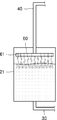
도4는 본 발명의 일 실시예에 따른 레독스 흐름전지를 도시한 도면이고, 도5는 도4의 요부를 발췌하여 도시한 도면이다. 도6은 도4의 전해액분배기의 저면도이고, 도7은 도4의 전해액분배기의 단면도이다. 4 is a view showing a redox flow battery according to an embodiment of the present invention, and FIG. 5 is a view showing an excerpt of the main part of FIG. 4. 6 is a bottom view of the electrolyte distributor of FIG. 4, and FIG. 7 is a cross-sectional view of the electrolyte distributor of FIG.
먼저 도4을 참고하면, 본 발명의 일 실시예에 따른 레독스 흐름전지(100)는, 전지셀(10), 전해액저장탱크(20), 공급유로(30), 회기유로(40), 압력제공부(50), 및 전해액분배기(60)를 포함한다. Referring first to Figure 4, the redox flow battery 100 according to an embodiment of the present invention, the
상기 전지셀(battery cell;10)은 전해액을 통해 충전 및 방전이 일어나는 최소 단위로서, 이온 교환이 일어나면서 충방전이 이루어지도록 분리막(13)과 상기 분리막(13)의 양측에 배치되는 양극(11), 음극(12), 분리판(14)을 포함하여 구성될 수 있다. 상기 전지셀(10) 자체의 구성은 공지된 구성에 의하므로, 그 구체적인 설명은 생략한다. The battery cell (battery cell) 10 is the smallest unit in which charging and discharging occurs through the electrolyte, and the
상기 전해액저장탱크(20)는 상기 전지셀(10)에 전해액을 공급하기 위해 마련된다. 본 실시예에 따르면, 상기 전해액공급부(20)는 상기 양극에 전해액을 공급하는 양극용 전해액저장탱크(21)과, 음극에 전해액을 공급하는 음극용 전해액저장탱크(22)를 포함한다. The
본 실시예에 따르면, 상기 전해액저장탱크(20)는 고무, 불소고무(fluorocarbon rubber), 폴리올레핀계 수지, 올레핀계 폴리에틸렌(PE), 염소화 폴리에틸렌, 폴리프로펠렌, 또는 폴리염화비닐계 수지 중에서 선택된 재료로 이루어진다. 상기 재료는 화학액에 내성을 갖는 소재로서 상기 저장탱크(20)의 내부가 전해액에 의해 부식되는 것을 예방한다. 한편, 상기 저장탱크(20)의 내벽면은 내화학성 코팅제를 이용하여 코팅될 수 있으며, 상기 코팅제로는 규소화합물, 붕소화합물, 또는 알루미늄화합물 등으로부터 선택될 수 있다. According to this embodiment, the
상기 공급유로(30)는 상기 전해액이 상기 전해액저장탱크(20)로부터 상기 전지셀(10)로 공급되도록, 상기 전해액저장탱크(20)와 상기 전지셀(10)을 연결한다. 상기 회기유로(40)는 상기 전해액이 상기 전지셀(10)로부터 상기 전해액저장탱크(20)로 회수되도록, 상기 전지셀(10)과 상기 전해액저장탱크(20)를 연결한다. The
상기 공급유로(30) 및 회기유로(40)는 상기 전지셀(10)의 양극 및 음극으로 전해액을 공급 및 회수하기 위해서, 상기 양극 측과 음극 측에 각각 마련된다. The
상기 압력제공부(50)는 상기 전해액저장탱크(20)와 상기 전지셀(10) 사이에서 상기 전해액을 순환시키는 압력을 제공한다. 상기 압력제공부(50)는 상기 전해액저장탱크(20)에 저장된 전해액에 압력을 가하여 상기 전해액을 상기 전지셀(10)로 유동시키기 위해서 마련된다. 상기 압력제공부(50)에 의해 상기 전해액은 상기 공급유로(30)를 통해 상기 전지셀(10)의 내부로 유동한다. The
본 실시예에 따르면, 상기 압력제공부(50)는 상기 공급유로(30)에 마련된 펌프로서, 상기 펌프의 압력에 의해 상기 전해액이 전지셀(10)로 유동하며, 상기 전지셀(10)의 내부에 존재하는 전해액은 상기 펌프압에 의해 밀려서 상기 전지셀(10)로부터 상기 전해액저장탱크(20)로 유동한다. 상기 펌프는 공압펌프, 전동펌프, 또는 유압펌프 등이 채용될 수 있다. 물론, 압력제공부(50)는 펌프 이외의 수단으로 직간접적으로 전해액에 압력을 가하는 구조로도 구현될 수 있다. According to this embodiment, the
상기 전해액분배기(60)는, 상기 전해액저장탱크(20)로 유입되는 전해액이 상기 전해액저장탱크(20)에 기 존재하는 전해액과 잘 섞일 수 있도록 하기 위해서 마련된다. 본 실시예에 있어서, 상기 전해액분배기(60)는 양극용 전해액저장탱크(21)와 음극용 전해액저장탱크(22)에 각각 마련된다. The
상기 전해액분배기(60)는 상기 전해액을 분산시키는 분사공(61)을 갖는다. 본 실시예에 따르면, 상기 전해액분배기(60)는 상기 회기유로(40)에 연결되며, 상기 전해액저장탱크(20)로 들어오는 상기 전해액을 분산시킬 수 있도록, 복수의 분사공(61)이 형성되어 있다. The
도4에 도시된 바와 같이, 본 발명의 일 실시예 따르면, 상기 분사공(61)의 직경(D1)은 상기 회기유로(40)의 직경(D2)보다 작다. 상기 전해액은 상기 전지셀(10)로부터 상기 압력제공부(50)의 압력에 의해 밀려서 상기 회기유로(40)를 통해서 상기 전해액저장탱크(20)로 유입된다. 이때, 상기 회기유로(40)의 직경(D2)보다 상기 분사공(61)의 직경(D1)이 작기 때문에, 상기 전해액은 면적이 좁아지는 영역을 지나면서 압력이 상승하여 전해액저장탱크(20)로 분사될 수 있다. As shown in Figure 4, according to an embodiment of the present invention, the diameter (D1) of the
또한, 본 실시에에 따르면, 상기 전해액분배기(60)는 상기 전해액저장탱크(20)의 상측에 마련되고, 상기 전해액은 상기 분사공(61)을 통해서 상측에서 하측으로 분사된다. 상기 전해액분재기(60)는 복수의 분사공(61)이 형성되어 있으므로, 상기 전해액저장탱크(20)의 수면에 대하여 복수의 지점에 전해액이 떨어지게 되므로, 상기 전해액저장탱크(20)에 기 존재하는 전해액과 새로 유입되는 전해액이 균일하고 용이하게 섞일 수 있게 된다. In addition, according to the present embodiment, the
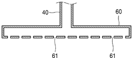
또한, 본 실시예에 따르면, 상기 전해액분배기(60)는 판형으로 형성되고, 상기 분사공(61)은 일정 간격으로 이격되어 형성된다. 도6에 도시된 바와 같이, 상기 판형의 전해액분배기(60)의 중심 측에 상기 회기유로(40)의 단부가 결합된다. 도7에 도시된 바와 같이, 상기 전해액분배기(60)는 내부에 전해액을 수용하는 공간이 형성되며, 하면에는 복수의 분사공(61)이 형성되어 있다. In addition, according to the present embodiment, the
상기 분사공(61)은 상기 전해액분배기(60)의 하면에 일정 간격으로 이격 배치된다. 상기 분사공(61)의 직경은 상기 회기유로(40)의 직경보다 작게 형성된다. 물론, 상기 전해액분배기(60)는 상기 판형 이외에, 일방향으로 연장되는 바(Bar) 형태 또는 바(Bar)가 서로 교차하는 십자형 등 다양한 형태로 구현될 수 있다. The injection holes 61 are spaced apart at regular intervals on the lower surface of the
도8은 본 발명의 다른 실시예에 따른 레독스 흐름전지를 도시한다. 본 실예에 따른 레독스 흐름전지에 있어서, 도4의 실시예와 동일한 작용 내지 기능을 수행하는 구성에 대하여는 동일한 참조번호를 부여하고, 그 구체적인 설명은 생략한다. 본 실시예에 따른 레독스 흐름전지는, 도4에 따른 레독스 흐름전지와 비교하여 전해액분배기(60)의 구성이 상이하다. 이하, 전해액분배기(60)의 구성에 대하여 구체적으로 설명한다. 8 shows a redox flow battery according to another embodiment of the present invention. In the redox flow battery according to the present embodiment, the same reference numerals are assigned to components that perform the same functions or functions as the embodiment of FIG. 4, and detailed descriptions thereof will be omitted. The redox flow battery according to the present embodiment has a different configuration of the
본 실시예에 채용된 상기 전해액분배기(60)는, 상기 전해액저장탱크(20)의 하측에 마련된다. 상기 전해액은 상기 전해액분배기(60)의 분사공(61)을 통해 하측에서 상측으로 분사된다. 또한, 본 실시예에 따르면, 공급유로(30)는 상기 전해액저장탱크(20)의 상측에 설치된다. The
따라서, 전지셀(10)로부터 유입된 전해액은 상기 전해액저장탱크(20)의 하부로부터 상측을 향하여 분사되고, 상기 공급유로(30)를 통해서 상기 전해액저장탱크(20)의 상측에 위치하는 전해액을 전지셀(10)로 공급하므로, 상기 전지셀(10)이 상측으로 유동하면서 혼합되게 된다.Therefore, the electrolyte solution introduced from the
본 실시예에 있어서, 상기 전해액분배기(60)의 분사공(61)은 상기 회기유로(40)의 직경보다 작다. 상기 전해액은 상기 압력제공부(50)의 압력에 의해 분사공(61)을 통해 분사되는 것으로, 별도의 기계적 장비를 요구하지 않는다. 또한, 상기 전해액분배기(60)는 판형으로 형성될 수 있다. 상기 판형은 도6과 같은 형태로 구현될 수 있다. 또한, 상기 분사공(61)은 상기 판형의 전해액분배기(60)에 일정 간격으로 이격되어 형성될 수 있다. In the present embodiment, the
물론, 본 실시예에 있어서, 상기 전해액분배기(60)는 상기 판형 이외에, 일방향으로 연장되는 바(Bar) 형태 또는 바(Bar)가 서로 교차하는 십자형 등 다양한 형태로 구현될 수 있다. Of course, in the present embodiment, the
도9는 본 발명의 또 다른 실시예에 따른 레독스 흐름전지를 도시한다. 본 실예에 따른 레독스 흐름전지에 있어서, 도8의 실시예와 동일한 작용 내지 기능을 수행하는 구성에 대하여는 동일한 참조번호를 부여하고, 그 구체적인 설명은 생략한다. 본 실시예에 따른 레독스 흐름전지는, 도8에 따른 레독스 흐름전지와 비교하여 전해액분배기(60)가 복수로 구비된 것이 상이하다. 이하, 전해액분배기(60)의 구성에 대하여 구체적으로 설명한다.9 shows a redox flow battery according to another embodiment of the present invention. In the redox flow battery according to the present embodiment, the same reference numerals are assigned to components that perform the same functions or functions as those in the embodiment of FIG. 8, and detailed descriptions thereof will be omitted. The redox flow battery according to the present embodiment is different from the redox flow battery according to FIG. 8 in that a plurality of
본 실시예에 채용된 전해액분배기(60)는, 상하 방향으로 서로 이격되어 복수 개 마련된다. 즉, 도9의 실시예에 따르면, 도8에 따른 전해액분배기(60)가 상하 방향으로 여러 개 마련된다. 본 실시예에 있어서, 상기 전해액분배기(60)는 3 개가 마련되어 있으나, 그 개수는 이에 한정되지 않는다. The
상기 전해액분배기(60)는, 도6과 같이 판형으로 이루어질 수 있다. 물론, 상기 전해액분배기(60)는 상기 판형 이외에, 일방향으로 연장되는 바(Bar) 형태 또는 바(Bar)가 서로 교차하는 십자형 등 다양한 형태로 구현될 수 있다. The
상기 공급유로(30)는, 도8의 실시예와 마찬가지로 상기 전해액저장탱크(20)의 상측에 마련되어 전해액을 전지셀(10)로 공급한다. The
본 실시예에 따르면, 상기 전해액은 상기 분사공(61)을 통하여 하측에서 상측으로 분사되며, 상기 전해액분배기(60)가 상기 전해액저장탱크(20)의 내부에 상하 방향으로 배치되므로 전해액은 더욱 균일하게 혼합될 수 있다. According to the present embodiment, the electrolyte is sprayed from the lower side to the upper side through the
도10은 본 발명 또 다른 실시예에 따른 레독스 흐름전지를 도시한다. 본 실예에 따른 레독스 흐름전지에 있어서, 도4의 실시예와 동일한 작용 내지 기능을 수행하는 구성에 대하여는 동일한 참조번호를 부여하고, 그 구체적인 설명은 생략한다. 본 실시예에 따른 레독스 흐름전지는, 도4에 따른 레독스 흐름전지와 비교하여 전해액분배기(60)의 구성이 상이하다. 이하, 전해액분배기(60)의 구성에 대하여 구체적으로 설명한다. 10 shows a redox flow battery according to another embodiment of the present invention. In the redox flow battery according to the present embodiment, the same reference numerals are assigned to components that perform the same functions or functions as the embodiment of FIG. 4, and detailed descriptions thereof will be omitted. The redox flow battery according to the present embodiment has a different configuration of the
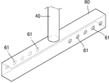
본 실시예에 있어서, 상기 전해액분배기(60)는 상기 회기유로(40)에 대하여 회전 가능하게 마련된다. 구체적으로, 상기 전해액분배기(60)는 수평바(62)를 포함하고, 상기 수평바(62)의 중심을 기준으로 좌우에 각각 형성된 분사공(61)에 의해 토출되는 전해액의 방향이 서로 반대로 이루어진다. In this embodiment, the
도11에 도시된 바와 같이, 상기 수평바(62)는 일방향으로 형성되는 막대형의 부재로서, 내부에 전해액이 수용되는 공간이 형성된다. 상기 수평바(62)는 상기 전해액저장탱크(20)의 내부에 수평 방향으로 배치된다. 상기 수평바(62)의 중심에 상기 회기유로(40)의 단부가 결합된다. 상기 회기유로(40)를 통해 들어온 전해액은 상기 수평바(62)의 양측으로 유동한다. As illustrated in FIG. 11, the horizontal bar 62 is a rod-shaped member formed in one direction, and a space in which the electrolyte is accommodated is formed. The horizontal bar 62 is disposed in a horizontal direction inside the
상기 수평바(62)의 중심을 기준으로 좌측에 배치되는 좌측부에 형성된 분사공(61)에 의한 전해액의 분사방향과, 우측에 배치되는 우측부에 형성된 상기 분사공(61)에 의한 전해액의 분사방향은 서로 반대이다. Based on the center of the horizontal bar 62, the injection direction of the electrolyte by the
도10을 기준으로, 우측에 형성된 분사공(61)을 통과한 전해액은 지면을 뚫고 들어가는 방향으로 토출되고, 좌측에 형성된 분사공(61)을 통과한 전해액은 지면으로부터 튀어나오는 방향으로 토출된다. 상술한 바와 같이, 상기 전해액이 토출되는 압력은 압력제공부(50)로부터 전달된다.Based on FIG. 10, the electrolyte that has passed through the
서로 반대 방향으로 토출되는 전해액에 의해 상기 전해액분배기(60)는, 상기 회기유로(40)가 결합된 중심을 기준으로 하여 회전한다. 상기 수평바(62)가 회전하면서, 전해액이 토출되므로, 전해액저장탱크(20)에 저장된 전해액의 균일하게 섞일 수 있다. The
물론, 본 실시예에 채용된 전해액분배기(60)는 수평바(62)의 형태로 이루어지나, 상기 수평바(62)가 2 개 교차하는 십자형, 또는 3개 교차하는 형태 등으로 다양하게 형태로 구현될 수 있다. Of course, the
도12 내지 도14는 본 발명 또 다른 실시예에 따른 레독스 흐름전지를 도시한다. 본 실예에 따른 레독스 흐름전지에 있어서, 도10의 실시예와 동일한 작용 내지 기능을 수행하는 구성에 대하여는 동일한 참조번호를 부여하고, 그 구체적인 설명은 생략한다. 본 실시예에 따른 레독스 흐름전지는, 도10에 따른 레독스 흐름전지와 비교하여 전해액분배기(60)의 구성이 상이하다. 이하, 전해액분배기(60)의 구성에 대하여 구체적으로 설명한다. 12 to 14 show a redox flow battery according to another embodiment of the present invention. In the redox flow battery according to the present embodiment, the same reference numerals are assigned to components that perform the same functions or functions as those of the embodiment of FIG. 10, and detailed descriptions thereof will be omitted. The redox flow battery according to this embodiment has a different configuration of the
본 실시예에 채용된 상기 전해액분배기(60)는, 상기 회기유로(40)에 대하여 회전 가능하게 결합되며, 상기 분사공(61)을 통해서 분사되는 상기 전해액의 분사방향이 상기 전해액분배기(60)가 놓이는 가상의 평면(P)과 소정의 각도를 갖도록 형성된다. The
도12 및 도13를 참조하면, 수평바(62)의 우측에 형성된 분사공(61)에 의해 전해액이 토출되는 방향은 상기 전해액분배기(60)가 놓이는 가상의 평면(P)과 소정의 각도(θ)를 이룬다. 마찬가지로, 도12 및 도14를 참조하면, 수평바(62)의 좌측에 형성된 분사공(61)에 의해 전해액이 토출되는 방향은 상기 전해액분배기(60)가 놓이는 가상의 평면(P)과 소정의 각도(θ)를 이룬다. 12 and 13, the direction in which the electrolyte is discharged by the
도12의 실시예에 따르면, 상기 분사공(61)이 수평바(62)의 측면에 형성되어 있으나, 상기 분사공(61)이 상기 수평바(62)의 상면에 기울어지게 형성되어 상기 수평바(62)가 회전하도록 구현될 수 있다. According to the embodiment of Figure 12, the
이와 같이, 상기 분사공(61)에 의해 토출되는 전해액이 상방향으로 비스듬이 분사되므로 전해액의 섞임을 좋게 하고, 회전하는 수평바(62)에 의해 전해액을 저어주게 되므로 섞임이 더욱 좋게 된다. As described above, since the electrolyte discharged by the
물론, 본 실시예에 따르면, 상기 전해액분배기(60)는 수평바(62) 형태로 형성되어 상기 분사공(61)이 좌우에서 서로 반대 방향으로 형성된 경우를 도시하였으나, 상기 분사공(61)이 비스듬이 형성된 실시예는 이에 한정되는 것이 아니다. 예컨대, 상기 전해액분배기(60)는 판 형태로 이루어질 수 있으며, 상기 분사공(61)은 동일한 방향으로 비스듬이 형성되어서, 상기 판 형태의 전해액분배기(60)를 회전시키는 형태로 구현될 수 있다. Of course, according to the present embodiment, the
도15는 본 발명의 또 다른 실시예에 따른 레독스 흐름전지를 도시한다. 본 실예에 따른 레독스 흐름전지에 있어서, 도4의 실시예와 동일한 작용 내지 기능을 수행하는 구성에 대하여는 동일한 참조번호를 부여하고, 그 구체적인 설명은 생략한다. 본 실시예에 따른 레독스 흐름전지는, 도4에 따른 레독스 흐름전지와 비교하여 전해액분배기(60)의 구성이 상이하다. 이하, 전해액분배기(60)의 구성에 대하여 구체적으로 설명한다. 15 shows a redox flow battery according to another embodiment of the present invention. In the redox flow battery according to the present embodiment, the same reference numerals are assigned to components that perform the same functions or functions as the embodiment of FIG. 4, and detailed descriptions thereof will be omitted. The redox flow battery according to the present embodiment has a different configuration of the
본 실시예에 채용된 전해액분배기(60)는 다공성 소재를 포함한다. 상기 다공성 소재로는 펠트(Felt), 직물, 또는 다공성폼(foam)이 사용될 수 있다. 상기 다공성 소재는 상기 회기유로(40)에 연결될 수 있을 정도의 두께를 가지고, 전해액이 상기 다공성 소재를 따라서 확산된 후 상기 전해액저장탱크(20)로 토출될 수 있을 정도로 형성된다. 상기 다공성 소재는 소정의 강도를 갖도록 하여 다공성 소재 단독으로 사용되거나, 또는 상기 다공성 소재가 별도의 케이싱(미도시)과 결합된 형태로 사용될 수 있다. The
본 실시예에서, 상기 분사공(61)은 상기 다공성 소재에 형성된 구멍이되며, 상기 다공성 소재는 불규칙적으로 구멍이 형성되므로, 이를 통해 토출되는 전해액은 상기 전해액저장탱크(20)에 기 저장된 전해액과 보다 균일하게 섞일 수 있게 된다. In the present embodiment, the
또한, 다공성 소재로 이루어지는 전해액분배기(60)는, 상기 전해액에 포함된 이물질을 제거하는 필터로서 기능할 수 있다. 레독스 흐름전지의 가동 중 전해액에 포함된 먼지, 반응부산물, 또는 전해액찌꺼기 등의 이물질은 상기 다공성 소재에 걸려 필터링되어 전지의 효율을 향상시킬 수 있다. In addition, the
본 실시예에 따르면, 상기 다공성 소재로 이루어지는 전해액분배기(60)는 전해액저장탱크(20)의 상측에 배치되어 있으나, 그 설치 위치는 이에 제한되지 않는다. According to this embodiment, the
도16은 본 발명의 또 다른 실시예에 따른 레독스 흐름전지를 도시한다. 본 실예에 따른 레독스 흐름전지에 있어서, 도8의 실시예와 동일한 작용 내지 기능을 수행하는 구성에 대하여는 동일한 참조번호를 부여하고, 그 구체적인 설명은 생략한다. 본 실시예에 따른 레독스 흐름전지는, 회기유로(40)가 전해액저장탱크(20)의 하측으로 연장되고, 상기 전해액분배기(60)가 상기 회기유로(40)의 단부에 연결될 때, 상기 전해액저장탱크(20)의 내부로 유입된 상기 회기유로(40)에 복수의 분사공(41)이 형성된다. 상기 회기유로(40)에 형성된 분사공(41)을 통해 분사되는 전해액은 전해액저장탱크(20)의 높이 방향에서 전해액이 균일하게 혼합되는데 기여한다.16 shows a redox flow battery according to another embodiment of the present invention. In the redox flow battery according to the present embodiment, the same reference numerals are assigned to components that perform the same functions or functions as those in the embodiment of FIG. 8, and detailed descriptions thereof will be omitted. In the redox flow battery according to the present embodiment, when the
도17은 본 발명의 또 다른 실시에에 따른 레독스 흐름전지를 도시한다. 본 실예에 따른 레독스 흐름전지에 있어서, 도5의 실시예와 동일한 작용 내지 기능을 수행하는 구성에 대하여는 동일한 참조번호를 부여하고, 그 구체적인 설명은 생략한다. 본 실시예에 따른 레독스 흐름전지에 따르면, 상기 전해액분배기(60)는 상기 회기유로(40)에 연결되어 나선상으로 회전하면서 연장되며, 상기 분사공(61)은 상기 전해액저장탱크(20)의 중심 측을 향하여 상기 전해액을 분사되도록 형성된다. 즉, 상기 분사공(61)은 나선 형상의 관의 내측 방향에 마련되고, 상기 나선 형상의 관의 단부로부터 전해액이 토출되는 것과 함께 상기 분사공(61)은 상기 전해액저장탱크(200의 중심 측을 향하여 상기 전해액을 분사한다. 17 shows a redox flow battery according to another embodiment of the present invention. In the redox flow battery according to the present embodiment, the same reference numerals are assigned to components that perform the same functions or functions as the embodiment of FIG. 5, and detailed descriptions thereof will be omitted. According to the redox flow battery according to the present embodiment, the
본 실시예에 따르면, 상기 나선상으로 형성되는 전해액분배기(60)는 상기 전해액저장탱크(20)의 내측면에 근접하여 배치된다. 상기 전해액분배기(60)는 상하방향으로 배치되므로, 상기 전해액저장탱크(20)의 높이 방향으로 전해액의 고른 혼합이 유도된다. 또한, 상기 분사공(61)은 나선상의 전해액분배기(60)에 형성되므로, 그 분사방향이 서로 상이하여 전해액의 균일한 혼합에 기여한다. According to the present embodiment, the
도18은 본 발명의 또 다른 실시예에 따른 레독스 흐름전지를 도시한다. 본 실예에 따른 레독스 흐름전지에 있어서, 도5의 실시예와 동일한 작용 내지 기능을 수행하는 구성에 대하여는 동일한 참조번호를 부여하고, 그 구체적인 설명은 생략한다. 본 실시예에 따른 레독스 흐름전지에 따르면, 상기 전해액분배기(60)는 상기 전해액저장탱크(20)의 내측에 소정의 간격을 갖도록 배치되는 내통부재(70)와, 상기 내통부재(70)에 마련된 복수의 분사공(71)과, 상기 내통부재와 상기 전해액저장탱크(20)가 서로 이격되어 형성되는 분배유로(72)를 포함한다.18 shows a redox flow battery according to another embodiment of the present invention. In the redox flow battery according to the present embodiment, the same reference numerals are assigned to components that perform the same functions or functions as the embodiment of FIG. 5, and detailed descriptions thereof will be omitted. According to the redox flow battery according to the present embodiment, the
본 실시예에 따르면, 전해액저장탱크(20)의 내측에 내통부재(70)가 마련된다. 상기 내통부재(70)에는 복수의 분사공(71)이 마련된다. 상기 회기유로(40)를 통해 전해액저장탱크(20) 측으로 유동하는 상기 전해액은 상기 분배유로(72)를 통해서 전해액저장탱크(20)로 유입된다. 상기 전해액은 상기 분사공(71)을 통해서 상기 전해액저장탱크(20)의 전면을 통해서 내측으로 분사될 수 있으므로, 전해액의 고른 혼합에 기여한다. 한편, 공급유로(30)의 단부는 상기 내통부재(70)의 내측으로 유입되어 배치된다. 상기 내통부재(70)에서 혼합된 전해액은 상기 공급유로(30)를 통해 전지셀(10)에 제공된다.According to this embodiment, the
이하, 상기 구성에 따른 레독스 흐름전지의 작용 내지 효과에 대하여 구체적으로 설명한다. 전해액이 양극으로 공급된 후 순환되는 과정과, 전해액이 음극으로 공급된 후 순환되는 과정은 동일하다. 따라서, 아래에서 전지셀(10)에서 전해액저장탱크(20)로 전해액이 유동할 때의 작용 내지 효과는, 전해액이 양극 측에서 순환할 때와 음극 측에서 순환할 때의 작용 내지 효과를 포함하는 것으로 이해되어야 한다. Hereinafter, the action or effect of the redox flow battery according to the above configuration will be described in detail. The process of circulating after the electrolyte is supplied to the anode and the process of circulating after the electrolyte is supplied to the cathode are the same. Therefore, the action or effect when the electrolyte flows from the
레독스 흐름전지는, 충전 및 방전 시 전해액의 물리적 또는 화학적 성질이 달라진다. 구체적으로, 전해액의 밀도, 점도와 같은 물리적 특성과 전하량과 같은 전기적 성질 또는 화학적 성질이 달라진다. Redox flow batteries have different physical or chemical properties of electrolytes during charging and discharging. Specifically, the physical properties, such as the density and viscosity of the electrolyte, and the electrical or chemical properties, such as the amount of charge, are different.
예컨대, 만약 충전된 전해액이 방전된 전해액보다 밀도가 높은 레독스 흐름전지라면, 충전 과정시 전지셀에서 전해액의 밀도가 높아지고, 전지셀로부터 전해액저장탱크로 회수되어 들어가는 전해액의 밀도는 이미 전해액저장탱크에 저장된 전해액보다 밀도가 높다. For example, if the charged electrolyte is a redox flow battery having a higher density than the discharged electrolyte, the density of the electrolyte in the battery cell increases during the charging process, and the density of the electrolyte recovered from the battery cell into the electrolyte storage tank is already in the electrolyte storage tank. Density is higher than the electrolyte stored in.
반대로, 방전 과정시 전지셀에서 전해액의 밀도가 낮아지고, 상기 전지셀로부터 전해액저장탱크로 회수되어 들어가는 번해액의 밀도는 이미 전해액저장탱크에 저장된 전해액보다 밀도가 낮다. On the contrary, the density of the electrolyte solution in the battery cell during the discharge process is lowered, and the density of the permeate recovered from the battery cell into the electrolyte storage tank is lower than that of the electrolyte solution already stored in the electrolyte storage tank.
레독스 흐름전지는 충전 및 방전이 반복적으로 이루어지고, 밀도의 변화를 야기한 전해액이 전해액저장탱크에 공존하기 때문에, 전해액저장탱크에서 전해액을 균일하게 섞어 주는 것은 레독스 흐름전지의 효율 및 수명이 매우 중요하다. Since the redox flow battery is repeatedly charged and discharged, and the electrolyte solution causing the change in density coexists in the electrolyte storage tank, uniformly mixing the electrolyte solution in the electrolyte storage tank is very effective in the efficiency and life of the redox flow battery. It is important.
상기한 실시예들은, 전지셀(10)로부터 충전 또는 방전을 거친 전해액이 다시 전해액저장탱크(20)로 유입될 때, 상기 전해액분배기(60)에 의해 전해액이 전해액저장탱크(20)에서 균일하게 혼합되는 효과를 제공한다. In the above-described embodiments, when the electrolyte solution that has been charged or discharged from the
또한, 상기 전해액분배기(60)로부터 전해액을 토출시키는 압력은, 전해액을 순환시키도록 압력을 제공하는 압력제공부(50)의 압력을 그대로 사용하므로, 전해액을 분사하기 위해서 별도의 장치를 요구하지 않는다. In addition, since the pressure for discharging the electrolyte from the
또한, 본 발명은 전해액분배기(60)에 의해 전해액이 분사되면서 혼합을 유도하는 구조로서, 전해액저장탱크 내부에 별도의 전원에 의해 기구를 구동시켜서 전해액을 혼합하지 않으므로, 별도 기구를 동작시키기 위한 전력 손실을 줄일 수 있으며, 레독스 흐름전지의 효율을 향상시킬 수 있다. In addition, the present invention is a structure that induces mixing while the electrolyte is sprayed by the
앞서 기술한 레독스 흐름전지의 전해액은 다양한 활물질이 사용될 수 있고, 충전 또는 방전 시에 밀도의 차이는 전해액의 성분에 따라 달라질 수 있으므로 충전 또는 방전 시 밀도의 변화는 앞서 기술한 방향과 반대일 수도 있다. 이 경우 본 발명의 목적에 부합하도록 전해액분배기(60)의 형상, 상하배치 또는 분사 방향을 변경할 수 있다.Various active materials may be used for the electrolyte of the redox flow battery described above, and the difference in density during charging or discharging may vary depending on the composition of the electrolyte, so the change in density during charging or discharging may be opposite to the direction described above. have. In this case, it is possible to change the shape of the
이상, 본 발명을 바람직한 실시예들을 들어 상세하게 설명하였으나, 본 발명은 상기 실시예들에 한정되지 않으며, 본 발명의 범주를 벗어나지 않는 범위 내에서 여러 가지 많은 변형이 제공될 수 있다.The present invention has been described in detail with reference to preferred embodiments, but the present invention is not limited to the above embodiments, and various modifications may be provided without departing from the scope of the present invention.
10... 전지셀 20... 전해액저장탱크
21... 양극용 전해액저장탱크 22... 음극용 전해액저장탱크
30... 공급유로 40... 회기유로
50... 압력제공부 60... 전해액분배기
61, 71... 분사공 62... 수평바
70... 내통부재 72... 분배유로10...
21... Electrolyte storage tank for
30...
50...
61, 71... jet hole 62... horizontal bar
70...
Claims (14)
상기 양극 및 상기 음극에 전해액을 공급하는 전해액저장탱크(20);
상기 전해액이 상기 전해액저장탱크(20)로부터 상기 전지셀(10)로 공급되도록, 상기 전해액저장탱크(20)과 상기 전지셀(10)을 연결하는 공급유로(30);
상기 전해액이 상기 전지셀(10)로부터 상기 전해액저장탱크(20)로 회수되도록, 상기 전지셀(10)과 상기 전해액저장탱크(20)를 연결하는 회기유로(40);
상기 전해액저장탱크(20)와 상기 전지셀(10) 사이에서 상기 전해액을 순환시키는 압력을 제공하는 압력제공부(50);
상기 전해액저장탱크(20)로 들어오는 상기 전해액을 분산시키는 분사공(61)이 형성된 전해액분배기(60);를 포함하는 것을 특징으로 하는 레독스 흐름전지. A battery cell 10 provided with an anode and a cathode;
An electrolyte storage tank 20 for supplying the electrolyte to the anode and the cathode;
A supply passage 30 connecting the electrolyte storage tank 20 and the battery cell 10 so that the electrolyte is supplied from the electrolyte storage tank 20 to the battery cell 10;
A return passage 40 connecting the battery cell 10 and the electrolyte storage tank 20 so that the electrolyte solution is recovered from the battery cell 10 to the electrolyte storage tank 20;
A pressure providing unit 50 that provides a pressure for circulating the electrolyte between the electrolyte storage tank 20 and the battery cell 10;
Redox flow battery characterized in that it comprises;; an electrolyte distributor (60) is formed with a spray hole (61) for dispersing the electrolyte that enters the electrolyte storage tank (20).
상기 분사공(61)의 직경은 상기 회기유로(40)의 직경보다 작은 것을 특징으로 하는 레독스 흐름전지. According to claim 1,
Redox flow battery, characterized in that the diameter of the injection hole 61 is smaller than the diameter of the recirculation passage (40).
상기 전해액분배기(60)는 상기 전해액저장탱크(20)의 상측에 마련되고,
상기 전해액은 상기 전해액분배기(60)의 분사공(61)을 통해 상측에서 하측으로 분사되는 것을 특징으로 하는 레독스 흐름전지. According to claim 1,
The electrolyte distributor 60 is provided on the upper side of the electrolyte storage tank 20,
The electrolyte is redox flow battery characterized in that the injection from the upper side to the lower side through the injection hole 61 of the electrolyte distributor (60).
상기 전해액분배기(60)는 판형으로 형성되고, 상기 분사공(61)은 일정 간격으로 이격되어 형성된 것을 특징으로 하는 레독스 흐름전지. According to claim 1,
The electrolyte distributor 60 is formed in a plate shape, the injection hole 61 is a redox flow battery characterized in that it is formed spaced apart at regular intervals.
상기 전해액분배기(60)는 상기 전해액저장탱크(20)의 하측에 마련되고,
상기 전해액은 상기 전해액분배기(60)의 분사공(61)을 통해 하측에서 상측으로 분사되는 것을 특징으로 하는 레독스 흐름전지. According to claim 1,
The electrolyte distributor 60 is provided on the lower side of the electrolyte storage tank 20,
The electrolyte is redox flow battery characterized in that the injection from the lower side to the upper side through the injection hole 61 of the electrolyte distributor (60).
상기 전해액분배기(60)는 상하 방향으로 서로 이격되어 복수 개 마련된 것을 특징으로 하는 레독스 흐름전지. The method of claim 5,
The electrolyte distributor 60 is a redox flow battery, characterized in that a plurality of spaced apart from each other in the vertical direction.
상기 전해액분배기(60)는 판형으로 형성되고, 상기 분사공(61)은 일정 간격으로 이격되어 형성된 것을 특징으로 하는 레독스 흐름전지. The method of claim 5 or 6,
The electrolyte distributor 60 is formed in a plate shape, the injection hole 61 is a redox flow battery characterized in that it is formed spaced apart at regular intervals.
상기 전해액분배기(60)는 상기 회기유로(40)에 대하여 회전하는 것을 특징으로 하는 레독스 흐름전지. According to claim 1,
The electrolyte distributor 60 is a redox flow battery, characterized in that rotates with respect to the recirculation flow path (40).
상기 전해액분배기(60)는 수평바(62)를 포함하고,
상기 수평바(62)의 중심에 상기 회기유로(40)의 단부가 결합되며,
상기 수평바(62)의 중심을 기준으로 좌측에 배치되는 좌측부에 형성된 상기 분사공(61)에 의한 상기 전해액의 분사방향과, 우측에 배치되는 우측부에 형성된 상기 분사공(61)에 의한 상기 전해액의 분사방향은 서로 반대인 것을 특징으로 하는 레독스 흐름전지. The method of claim 8,
The electrolyte distributor 60 includes a horizontal bar (62),
At the center of the horizontal bar 62, the end of the recirculation passage 40 is coupled,
Based on the center of the horizontal bar 62, the injection direction of the electrolytic solution by the injection hole 61 formed on the left side disposed on the left side, and by the injection hole 61 formed on the right side disposed on the right side Redox flow battery characterized in that the injection direction of the electrolyte is opposite to each other.
상기 전해액분배기(60)로부터 상기 분사공(61)을 통해서 분사되는 상기 전해액의 분사방향은 상기 전해액분배기(60)가 놓이는 가상의 평면과 소정의 각도를 갖는 것을 특징으로 하는 레독스 흐름전지. The method of claim 8,
Redox flow battery, characterized in that the injection direction of the electrolyte injected from the electrolyte distributor (60) through the injection hole (61) has a predetermined angle with a virtual plane on which the electrolyte distributor (60) is placed.
상기 전해액분배기(60)는 다공성 소재를 포함하며,
상기 분사공(61)은 상기 다공성 소재에 형성된 구멍인 것을 특징으로 하는 레독스 흐름전지. According to claim 1,
The electrolyte distributor 60 includes a porous material,
The injection hole 61 is a redox flow battery, characterized in that the hole formed in the porous material.
상기 다공성 소재는 펠트, 직물, 또는 다공성폼인 것을 특징으로 하는 레독스 흐름전지.The method of claim 11,
The porous material is a redox flow battery, characterized in that the felt, fabric, or porous foam.
상기 전해액분배기(60)는, 상기 회기유로(40)에 연결되어 나선상으로 회전하면서 연장되며, 상기 분사공(61)은 상기 전해액저장탱크(20)의 중심측을 향하여 상기 전해액을 분사되도록 형성된 것을 특징으로 하는 레독스 흐름전지.According to claim 1,
The electrolyte distributor 60 is connected to the return passage 40 and extends while rotating in a spiral, and the injection hole 61 is formed to spray the electrolyte toward the center of the electrolyte storage tank 20 Redox flow battery characterized by.
상기 전해액분배기(60)는, 상기 전해액저장탱크(20)의 내측에 소정의 간격을 갖도록 배치되며 내통부재(70)와, 상기 내통부재(70)에 마련된 복수의 분사공(71), 및 상기 내통부재와 상기 전해액저장탱크(20)가 서로 이격되어 형성되는 분배유로(72)를 포함하는 것을 특징으로 하는 레독스 흐름전지.
According to claim 1,
The electrolyte distributor 60 is disposed to have a predetermined interval inside the electrolyte storage tank 20, the inner cylinder member 70, a plurality of injection holes 71 provided in the inner cylinder member 70, and Redox flow battery, characterized in that it comprises a distribution passage 72 formed by the inner cylinder member and the electrolyte storage tank 20 are spaced apart from each other.
Priority Applications (1)
| Application Number | Priority Date | Filing Date | Title |
|---|---|---|---|
| KR1020180173065A KR102195851B1 (en) | 2018-12-28 | 2018-12-28 | Redox flow battery |
Applications Claiming Priority (1)
| Application Number | Priority Date | Filing Date | Title |
|---|---|---|---|
| KR1020180173065A KR102195851B1 (en) | 2018-12-28 | 2018-12-28 | Redox flow battery |
Publications (2)
| Publication Number | Publication Date |
|---|---|
| KR20200082458A true KR20200082458A (en) | 2020-07-08 |
| KR102195851B1 KR102195851B1 (en) | 2020-12-28 |
Family
ID=71600599
Family Applications (1)
| Application Number | Title | Priority Date | Filing Date |
|---|---|---|---|
| KR1020180173065A KR102195851B1 (en) | 2018-12-28 | 2018-12-28 | Redox flow battery |
Country Status (1)
| Country | Link |
|---|---|
| KR (1) | KR102195851B1 (en) |
Cited By (3)
| Publication number | Priority date | Publication date | Assignee | Title |
|---|---|---|---|---|
| KR20220076171A (en) | 2020-11-30 | 2022-06-08 | 남도금형(주) | Redox flow battery with improved electrolyte ion precipitation problem |
| KR20230064457A (en) | 2021-11-03 | 2023-05-10 | 남도금형(주) | Photocatalytic filter structure for redox flow battery |
| EP4246635A1 (en) * | 2022-02-16 | 2023-09-20 | Kermi GmbH | Redox flow battery and means for improved mixing of the electrolyte in the tanks |
Citations (3)
| Publication number | Priority date | Publication date | Assignee | Title |
|---|---|---|---|---|
| KR100647422B1 (en) | 2005-02-12 | 2006-11-24 | 이보름 | air diffuser system equipped with air-dome for preventing water hammer impact |
| KR101443209B1 (en) * | 2013-08-16 | 2014-09-22 | 한국에너지기술연구원 | Redox flow battery |
| CN206849952U (en) * | 2017-07-11 | 2018-01-05 | 大连融科储能技术发展有限公司 | Electrolyte storage tank and the flow battery system with the electrolyte storage tank |
-
2018
- 2018-12-28 KR KR1020180173065A patent/KR102195851B1/en active IP Right Grant
Patent Citations (3)
| Publication number | Priority date | Publication date | Assignee | Title |
|---|---|---|---|---|
| KR100647422B1 (en) | 2005-02-12 | 2006-11-24 | 이보름 | air diffuser system equipped with air-dome for preventing water hammer impact |
| KR101443209B1 (en) * | 2013-08-16 | 2014-09-22 | 한국에너지기술연구원 | Redox flow battery |
| CN206849952U (en) * | 2017-07-11 | 2018-01-05 | 大连融科储能技术发展有限公司 | Electrolyte storage tank and the flow battery system with the electrolyte storage tank |
Cited By (3)
| Publication number | Priority date | Publication date | Assignee | Title |
|---|---|---|---|---|
| KR20220076171A (en) | 2020-11-30 | 2022-06-08 | 남도금형(주) | Redox flow battery with improved electrolyte ion precipitation problem |
| KR20230064457A (en) | 2021-11-03 | 2023-05-10 | 남도금형(주) | Photocatalytic filter structure for redox flow battery |
| EP4246635A1 (en) * | 2022-02-16 | 2023-09-20 | Kermi GmbH | Redox flow battery and means for improved mixing of the electrolyte in the tanks |
Also Published As
| Publication number | Publication date |
|---|---|
| KR102195851B1 (en) | 2020-12-28 |
Similar Documents
| Publication | Publication Date | Title |
|---|---|---|
| US10886552B2 (en) | Electrochemical system for storing electricity in metals | |
| US8137831B1 (en) | Electrolyte flow configuration for a metal-halogen flow battery | |
| JP6263127B2 (en) | Electrically rechargeable metal anode cell and battery system and method | |
| KR102195851B1 (en) | Redox flow battery | |
| KR101394255B1 (en) | Redox flow battery and operration method of the same | |
| US20120328910A1 (en) | Electrolyte Flow Configuration for a Metal-Halogen Flow Battery | |
| KR101752890B1 (en) | Redox flow battery | |
| JP2013537686A (en) | Electrically rechargeable metal-air battery system and method | |
| US9153832B2 (en) | Electrochemical cell stack having a protective flow channel | |
| US20200388867A1 (en) | Redox flow battery having electrolyte flow path independently provided therein | |
| US20130045399A1 (en) | Flow Battery with Reactant Separation | |
| CN109845012B (en) | Redox flow battery including system for reducing bypass current | |
| KR101855290B1 (en) | Redox flow battery | |
| CN107534161B (en) | Grid type flow battery structure | |
| KR20200073509A (en) | Zinc-bromide flow battery comprising conductive interlayer | |
| KR101760983B1 (en) | Flow battery and method of preventing mix of the electrolyte | |
| KR101570700B1 (en) | Manifold and Redox Flow Battery Including the Same | |
| US9184454B1 (en) | Mixing arrangement for a flow cell of an energy storage system | |
| JP7149623B2 (en) | redox flow battery | |
| KR20160136266A (en) | Lattice type flow cell structure | |
| KR101443209B1 (en) | Redox flow battery | |
| JP6629911B2 (en) | Redox flow battery | |
| KR102673209B1 (en) | Battery system and working machine having the same | |
| KR20180031998A (en) | Apparatus for mixing of electrolyte for redox flow battery | |
| KR102147948B1 (en) | Redox flow battery |
Legal Events
| Date | Code | Title | Description |
|---|---|---|---|
| E701 | Decision to grant or registration of patent right | ||
| GRNT | Written decision to grant |