KR20200081868A - Toc measuring system using high frequency heating combustion - Google Patents
Toc measuring system using high frequency heating combustion Download PDFInfo
- Publication number
- KR20200081868A KR20200081868A KR1020180171831A KR20180171831A KR20200081868A KR 20200081868 A KR20200081868 A KR 20200081868A KR 1020180171831 A KR1020180171831 A KR 1020180171831A KR 20180171831 A KR20180171831 A KR 20180171831A KR 20200081868 A KR20200081868 A KR 20200081868A
- Authority
- KR
- South Korea
- Prior art keywords
- sample
- unit
- frequency
- heating unit
- supplied
- Prior art date
Links
Images


Classifications
-
- G—PHYSICS
- G01—MEASURING; TESTING
- G01N—INVESTIGATING OR ANALYSING MATERIALS BY DETERMINING THEIR CHEMICAL OR PHYSICAL PROPERTIES
- G01N25/00—Investigating or analyzing materials by the use of thermal means
- G01N25/20—Investigating or analyzing materials by the use of thermal means by investigating the development of heat, i.e. calorimetry, e.g. by measuring specific heat, by measuring thermal conductivity
-
- G—PHYSICS
- G01—MEASURING; TESTING
- G01N—INVESTIGATING OR ANALYSING MATERIALS BY DETERMINING THEIR CHEMICAL OR PHYSICAL PROPERTIES
- G01N33/00—Investigating or analysing materials by specific methods not covered by groups G01N1/00 - G01N31/00
- G01N33/18—Water
- G01N33/1826—Water organic contamination in water
Abstract
Description
본 발명은 고주파 가열 연소를 이용한 TOC 측정 시스템에 관한 것으로, 더욱 상세하게는 측정하고자 하는 시료를 고주파 가열하여 유기물을 산화시켜 CO2가 발생되도록 하여 시료에 포함된 유기물의 양을 측정할 수 있는 고주파 가열 연소를 이용한 TOC 측정 시스템에 관한 것이다.The present invention relates to a TOC measurement system using high-frequency heating combustion, and more specifically, high-frequency heating capable of measuring the amount of organic substances contained in the sample by heating the sample to be measured by high-frequency heating to oxidize organic substances to generate CO2. It relates to a TOC measurement system using combustion.
TOC(total organic carbon), COD(chemical oxygen demand) 및 BOD(biological oxygen demand) 등은 모두 유기물에 의한 수질오염을 판단할 수 있는 항목들이다. TOC, COD 및 BOD는 각각 시험 조건이나 산화율이 다르기 때문에 적용항목이나 적용기준이 다르다.Total organic carbon (TOC), chemical oxygen demand (COD), and biological oxygen demand (BOD) are all items that can determine water pollution by organic matter. TOC, COD, and BOD have different test conditions or oxidation rates, so they have different application items or application standards.
이 중 TOC 및 COD는 물리화학적인 측정방법이고, BOD는 생물화학적인 측정방법이기 때문에 대부분의 나라에서 각종 수질 기준을 적용할 때, BOD를 기본으로 적용한다. 그리고 TOC 및 COD 중 하나를 BOD와 함께 적용하여 상호 보완적인 체계가 이루어지도록 한다.Of these, TOC and COD are physicochemical measurement methods, and BOD is a biochemical measurement method, so when applying various water quality standards in most countries, BOD is applied as a basis. Also, one of TOC and COD is applied together with BOD so that a complementary system can be achieved.
현재 우리나라는, 유기물 오염지표로 BOD5와 CODMn을 적용하고 있으며, 이 두 항목은 대략 탄소계 유기물의 약 60~80% 정도 산화에 필요한 산소 요구량을 측정할 수 있다. 반면, TOC 및 TOD(total oxygen demand)는 약 95% 이상의 산화에 필요한 산소요구량을 측정할 수 있어, 미국, 독일, 일본 등에서는 기존의 BOD나 COD 항목 외에 TOC 항목을 도입하여 유기성 오염물질의 농도를 측정하고 있다. 또한, TOC 분석기는 측정 값의 분석에 약 1~2분 정도의 짧은 시간만 소요되는 장점이 있다.Currently, in Korea, BOD5 and CODMn are applied as indicators of organic contamination, and these two items can measure the oxygen demand for oxidation of approximately 60 to 80% of carbon-based organic matter. On the other hand, TOC and TOD (total oxygen demand) can measure the amount of oxygen required for oxidation of about 95% or more. In the United States, Germany, and Japan, the concentration of organic pollutants by introducing TOC items in addition to the existing BOD or COD items Is measuring. In addition, the TOC analyzer has an advantage that it takes only a short time of about 1 to 2 minutes to analyze the measured value.
TOC는 시료 중에 포함된 유기물을 고온에서 CO2로 산화시켜 그 발생량을 분석 장치로 측정하여 총 유기 탄소량을 산정할 수 있다. 따라서 일반적인 모든 TOC 분석기는 크게 두 단계를 거쳐 측정이 이루어진다. 첫 번째 단계는, 시료 속에 모든 유기 화합물을 CO2로 산화하는 과정이고, 두 번째 단계는, 유기물의 산화로 생성된 CO2를 전도도나 비분산 적외선 분광법(NDIR) 등으 기타 방법을 이용하여 정량하는 검출 과정이다.TOC can calculate the total amount of organic carbon by oxidizing the organic matter contained in the sample to CO2 at a high temperature and measuring the generated amount with an analytical device. Therefore, all typical TOC analyzers are measured in two steps. The first step is a process of oxidizing all organic compounds into CO2 in a sample, and the second step is a detection process of quantifying CO2 generated by oxidation of an organic material using conductivity or non-dispersive infrared spectroscopy (NDIR). to be.
이때, 시료 속에 모든 유기 화합물을 CO2로 산화하는 과정은 자외선(UV)과 산화제법을 이용한 방법, 산화제와 가열법을 이용한 방법, 고온연소 산화법, 자외선을 이용한 방법 등을 적용할 수 있다. 이러한 방법들 중 고온연소 산화법은 산화효율이 우수하고 입자형태의 시료와 고농도의 유기 폐수를 분석할 수 있기 때문에 많이 이용된다. 고온연소 산화법은 약 680℃의 고온으로 시료를 가열하여 산화시키는데, 이때, 공기와 CO2의 고순도 가스가 필요하여 백금 촉매가 사용될 수 있다.At this time, the process of oxidizing all organic compounds into CO2 in the sample may be a method using an ultraviolet (UV) method and an oxidizing agent method, a method using an oxidizing agent and a heating method, a high temperature combustion oxidation method, or a method using ultraviolet rays. Among these methods, the high-temperature combustion oxidation method is widely used because it has excellent oxidation efficiency and can analyze a sample in a particle form and a high concentration of organic wastewater. The high temperature combustion oxidation method oxidizes the sample by heating it to a high temperature of about 680° C. At this time, a high purity gas of air and CO 2 is required, so a platinum catalyst can be used.
대한민국 등록특허 제10-1587559호 및 대한민국 등록특허 제10-1531395호는 고온연소 산화방식으로 시료의 유기물을 산화시키는 방법이 개시된다. 하지만, 종래의 대부분의 고온연소 산화방법은 주로 발열코일을 이용하여 시료를 가열하는 방식이 이용되는데, 이렇게 코일에서 발생된 열은 시료까지 전달되는 시간이 오래 걸리고 고온으로 발열시키기 위해 소모되는 전력이 많은 단점이 있다.Republic of Korea Patent Registration No. 10-1587559 and Republic of Korea Patent Registration No. 10-1531395 discloses a method for oxidizing the organic matter of the sample in a high temperature combustion oxidation method. However, most of the conventional high-temperature combustion oxidation methods mainly use a method of heating a sample using a heating coil, and the heat generated from the coil takes a long time to transfer to the sample and the power consumed to generate heat at a high temperature There are many disadvantages.
본 발명이 해결하고자 하는 과제는, 측정 시료를 고주파 가열하여 유기물을 산화시켜 CO2를 발생시킬 수 있는 고주파 가열 연소를 이용한 TOC 측정 시스템을 제공하는 것이다.The problem to be solved by the present invention is to provide a TOC measurement system using high-frequency heating combustion that can generate CO2 by oxidizing organic substances by heating a measurement sample at high frequency.
본 발명의 일 실시예에 따른 고주파 가열 연소를 이용한 TOC 측정 시스템은, 시료를 저장되는 시료 공급부; 상기 시료 공급부에서 공급되는 시료와 함께 이산화탄소가 제거된 공기가 공급되는 공기 공급부; 상기 시료 공급부 및 공기 공급부에서 시료 및 공기가 공급되고, 공급된 시료를 고주파로 연소시켜 이산화탄소를 발생시키는 고주파 연소 장치; 및 상기 고주파 연소 장치에서 배출되는 이산화탄소를 검출하는 이산화탄소 검출기를 포함하고, 상기 고주파 연소 장치는, 탄소를 포함하는 시료가 공급되어 배치되는 시료 가열부; 상기 시료 가열부를 둘러싸도록 배치되며, 상기 시료 가열부에 열을 가하는 발열부; 상기 발열부를 감싸도록 배치된 절연부; 및 상기 절연부를 감싸도록 배치되고, 공급된 전력으로 고주파를 발생시키는 고주파부를 포함할 수 있다.TOC measurement system using high-frequency heating combustion according to an embodiment of the present invention, a sample supply unit for storing a sample; An air supply unit through which carbon dioxide-removed air is supplied together with a sample supplied from the sample supply unit; A high-frequency combustion device in which samples and air are supplied from the sample supply unit and the air supply unit, and the supplied samples are burned at high frequencies to generate carbon dioxide; And a carbon dioxide detector for detecting carbon dioxide discharged from the high frequency combustion device, wherein the high frequency combustion device comprises: a sample heating unit in which a sample containing carbon is supplied and arranged; A heating unit disposed to surround the sample heating unit and applying heat to the sample heating unit; An insulation portion disposed to surround the heating portion; And it is disposed to surround the insulating portion, it may include a high-frequency portion for generating a high frequency with the supplied power.
상기 고주파 연소 장치에서 발생된 이산화탄소가 포함된 기체를 냉각시키는 냉각부를 더 포함하고, 상기 고주파 연소 장치에 포함된 고주파부는, 상기 냉각부에 포함된 물이 통과할 수 있도록 관의 형상으로 형성될 수 있다.Further comprising a cooling unit for cooling the gas containing carbon dioxide generated in the high-frequency combustion device, the high-frequency portion included in the high-frequency combustion device, may be formed in the shape of a tube to allow the water contained in the cooling unit to pass have.
상기 고주파부는 관의 형상이 상기 절연부의 외주면을 따라 나선 형상으로 감싸도록 배치될 수 있다.The high-frequency portion may be arranged such that the shape of the tube wraps in a spiral shape along the outer circumferential surface of the insulating portion.
상기 고주파부는 상기 절연부의 외주면을 두 겹 이상 감싸도록 배치될 수 있다.The high-frequency portion may be disposed to surround two or more layers of the outer peripheral surface of the insulating portion.
상기 발열부는 상기 시료 가열부의 하단을 감싸도록 배치되고, 상기 시료 가열부는 상기 시료 가열부의 상부를 관통하여 상기 시료 가열부의 내측 하단까지 연장된 시료 공급관을 포함할 수 있다.The heating unit may be disposed to surround the lower end of the sample heating unit, and the sample heating unit may include a sample supply pipe penetrating the upper portion of the sample heating unit and extending to an inner lower end of the sample heating unit.
상기 고주파 연소 장치에 물을 공급하는 물 공급부를 더 포함하고, 상기 물 공급부는 상기 시료 가열부의 내부를 세척하기 위해 상기 시료 공급관을 통해 물을 공급할 수 있다.Further comprising a water supply unit for supplying water to the high-frequency combustion device, the water supply unit may supply water through the sample supply pipe to clean the interior of the sample heating unit.
상기 물 공급관에서 상기 시료 공급관으로 공급되는 물과 함께 상기 공기 공급부에서 공급된 공기가 상기 시료 공급관을 통해 상기 시료 가열부에 공급할 수 있다.Air supplied from the air supply unit together with water supplied from the water supply pipe to the sample supply pipe may be supplied to the sample heating unit through the sample supply pipe.
본 발명에 의하면, 측정 시료를 고주파로 가열하여 유기물을 산화시키기 때문에 에너지 소모량을 감소시킬 수 있으며, 산화 시간이 줄어들어 TOC 측정 시간을 최소화할 수 있는 효과가 있다.According to the present invention, since the measurement sample is heated at a high frequency to oxidize an organic substance, energy consumption can be reduced, and the oxidation time is reduced, thereby minimizing the TOC measurement time.
더욱이, 고주파를 인가하기 위해 구비된 고주파부의 내부에 발열부를 냉각시킬 수 있도록 냉각수가 흐를 수 있는 냉각관이 형성되어 반복적으로 시료를 측정하더라도 안정성을 유지할 수 있는 효과가 있다.Moreover, a cooling tube through which cooling water flows is formed so as to cool the heating portion inside the high-frequency portion provided to apply the high-frequency portion, thereby maintaining stability even when the sample is repeatedly measured.
도 1은 본 발명의 일 실시예에 따른 고주파 가열 연소를 이용한 TOC 측정 시스템을 도시한 도면이다.
도 2는 본 발명의 일 실시예에 따른 고주파 가열 연소를 이용한 TOC 측정 시스템의 고주파 연소 장치를 도시한 도면이다.
도 3은 본 발명의 일 실시예에 따른 고주파 가열 연소를 이용한 TOC 측정 시스템의 고주파 연소 장치를 도시한 분해 사시도이다.
도 4는 본 발명의 일 실시예에 따른 고주파 가열 연소를 이용한 TOC 측정 시스템의 고주파 연소 장치에 포함된 시료 가열부를 설명하기 위한 도면이다.
도 5는 본 발명의 다른 실시예에 따른 고주파 가열 연소를 이용한 TOC 측정 시스템의 고주파 연소 장치에 포함된 시료 가열부를 설명하기 위한 도면이다.1 is a view showing a TOC measurement system using high-frequency heating combustion according to an embodiment of the present invention.
2 is a view showing a high-frequency combustion apparatus of the TOC measurement system using high-frequency heating combustion according to an embodiment of the present invention.
3 is an exploded perspective view showing a high-frequency combustion apparatus of a TOC measurement system using high-frequency heating combustion according to an embodiment of the present invention.
4 is a view for explaining a sample heating unit included in the high-frequency combustion apparatus of the TOC measurement system using high-frequency heating combustion according to an embodiment of the present invention.
5 is a view for explaining a sample heating unit included in the high-frequency combustion apparatus of the TOC measurement system using high-frequency heating combustion according to another embodiment of the present invention.
본 발명의 바람직한 실시예에 대하여 첨부된 도면을 참조하여 더 구체적으로 설명한다.With reference to the accompanying drawings, a preferred embodiment of the present invention will be described in more detail.
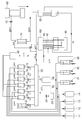
도 1은 본 발명의 일 실시예에 따른 고주파 가열 연소를 이용한 TOC 측정 시스템을 도시한 도면이다.1 is a view showing a TOC measurement system using high-frequency heating combustion according to an embodiment of the present invention.
도 1을 참조하여, 본 발명의 일 실시예에 따른 고주파 가열 연소를 이용한 TOC 측정 시스템에 대해 설명한다.Referring to FIG. 1, a TOC measurement system using high-frequency heating combustion according to an embodiment of the present invention will be described.
먼저, 고주파 연소 장치(100)에 시료를 공급하기 전에, 교정액을 고주파 연소 장치(100)에 공급한다. 이를 위해, 제1 및 제2 교정액 공급부(11, 12)에서 교정액이 제1 내지 제6 중간액 공급부(15 ~ 20)와 병합부(22)를 거쳐 고주파 연소 장치(100)에 공급될 수 있다. 그리고 공기 공급부에서 공급된 공기가 제1 필터(24)와 제1 및 제2 이산화탄소 제거부(25, 26)를 통해 병합부(22)에서 교정액과 함께 고주파 연소 장치(100)에 공급될 수 있다.First, before supplying a sample to the high
제1 내지 제6 중간액 공급부(15 ~ 20)는 각각 매니폴드(60)와 연결되며, 매니폴드(60)는 제습기(70)와 연결될 수 있다. 그리고 매니폴드(60)는 외부로 공기 분사함에 따라 제습기(70)로 공급된 기체에서 수분을 제거할 수 있다.The first to sixth intermediate
제1 및 제2 이산화탄소 제거부(25, 26)는 공기에 포함된 이산화탄소를 제거하기 위해 구비되며, 제1 및 제2 이산화탄소 제거부(25, 26)를 차례로, 공기가 거치면서 공기 내에 이산화탄소가 제거될 수 있다. 이렇게 이산화산소가 제거된 공기가 병합부(22)에서 교정액과 혼합된 상태로 고주파 연소 장치(100)에 공급될 수 있다.The first and second carbon
그리고 고주파 연소 장치(100)는 구동되어 공급된 교정액을 연소시켜 산화시킬 수 있다. 그에 따라 교정액이 연소되면서 발생된 기체는 제습기(70)를 거쳐 이산화탄소 검출기(80)를 통해 기체 내에 포함된 이산화탄소의 양을 측정할 수 있다. 이때, 이산화탄소 검출기(80)로 공급되는 기체는 제2 필터(72)를 거쳐 공급될 수 있다.In addition, the high-
이때, 교정액에 의해 이산화탄소의 양을 측정함에 따라 이후 시료에 포함된 이산화탄소의 양을 측정할 때, TOC 측정 시스템의 시험 과정에 발생하는 오류를 교정할 수 있다. 교정액에는 정해진 유기물이 포함될 수 있다.At this time, when measuring the amount of carbon dioxide contained in the sample as the amount of carbon dioxide is measured by the calibration solution, errors occurring in the test process of the TOC measurement system can be corrected. The calibration fluid may contain a predetermined organic material.
여기서, 고주파 연소 장치(100)는 고주파 발생부(40)와 전기적으로 연결될 수 있다. 따라서 고주파 발생부(40)에서 공급된 전력에 의해 고주파 연소 장치(100)에서 고주파가 발생하여 시료를 연소시킬 수 있다.Here, the high
상기와 같이, 교정이 이루어진 다음, 오프라인액(off-line liquid) 및 희석액(dilution water)이 각각 오프라인액 공급부(13) 및 희석액 공급부(14)에서 공급되어 고주파 연소 장치(100)에 공급될 수 있다.As described above, after the calibration is made, the off-line liquid and the dilution water are supplied from the off-line
그리고 측정하고자 하는 시료가 제1 및 제2 시료 공급부(31, 32) 중 어느 하나 이상에서 고주파 연소 장치(100)에 공급될 수 있다. 이때, 제1 및 제2 시료 공급부(31, 32) 중 어느 하나 이상에서 공급된 시료는 교정액과 마찬가지 경로를 통해 고주파 연소 장치(100)에 공급될 수 있다.And the sample to be measured can be supplied to the high-
따라서 고주파 연소 장치(100)에 공급된 시료는 병합부(22)에서 이산화탄소가 제거된 공기와 함께 고주파 연소 장치(100)에 공급된다. 그리고 고주파 연소 장치(100)가 구동됨에 따라 시료가 연소되면서 기체를 발생시키고, 발생된 기체는, 고주파 연소 장치(100)에서 배출되어 냉각부(50)로 공급되어 냉각된다. 그리고 냉각된 기체는, 제습기(70)로 공급되며, 제습기(70)에서 냉각된 기체에 포함된 수분을 제거한 다음, 이산화탄소 검출기(80)에서 수분이 제거된 기체 내에 포함된 이산화탄소의 양을 측정할 수 있다. 이때, 이산화탄소의 양을 측정함으로써, 이산화탄소에 포함된 탄소의 양을 산정할 수 있고, 또한, 산정된 탄소의 양을 통해 시료에 포함된 유기물의 양을 측정할 수 있다.Therefore, the sample supplied to the high-
여기서, 고주파 연소 장치(100)에 시료와 이산화탄소가 제거된 공기가 공급됨에 따라 시료가 연소하면서 발생하는 탄소가 공기의 산소와 결합하여 이산화탄소가 생성될 수 있다. 그에 따라 이산화탄소 검출부에서 검출되는 이산화탄소에 포함된 탄소는 유기물에 포함된 탄소일 수 있다.Here, as the sample and the carbon dioxide-removed air are supplied to the high-
그리고 시료에 대한 측정이 완료되면, 고주파 연소 장치(100)가 고온인 상태가 유지되므로, 고주파 연소 장치(100)를 냉각하기 위해 물 공급부(33)에서 물이 고주파부(150)에 형성된 냉각관(152)으로 공급될 수 있다. 따라서 냉각관(152)을 따라 물이 이동하면서, 고주파부(150)에 의해 발열된 발열부(160)의 온도를 낮출 수 있다. 그리고 냉각관(152)에서 배출된 물은 내각부로 공급되고, 냉각부(50)의 물은 물 공급부(33)로 다시 공급되어, 냉각관(152)을 통해 흐르는 물은 물 공급부(33), 고주파 연소 장치(100) 및 냉각부(50)를 순환하도록 구성될 수 있다.And when the measurement of the sample is completed, since the high-
그리고 필요에 따라 물 공급부(33)에서 공급되는 물은 시료 공급관(142)을 통해 시료 가열부(140)를 채울 수 있다. 그에 따라 시료 공급관(142)에 공급된 물은 시료 가열부(140)의 내부를 공급된 물로 청소가 이루어지도록 할 수 있다. 또한, 병합부(22)에서 이산화탄소가 제거된 공기가 물과 함께 공급됨에 따라 시료 가열부(140)의 내부를 물과 공기를 이용하여 청소가 이루어지도록 할 수 있다.And, if necessary, water supplied from the
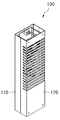
도 2는 본 발명의 일 실시예에 따른 고주파 가열 연소를 이용한 TOC 측정 시스템의 고주파 연소 장치를 도시한 도면이고, 도 3은 본 발명의 일 실시예에 따른 고주파 가열 연소를 이용한 TOC 측정 시스템의 고주파 연소 장치를 도시한 분해 사시도이다. 도 4는 본 발명의 일 실시예에 따른 고주파 가열 연소를 이용한 TOC 측정 시스템의 고주파 연소 장치에 포함된 시료 가열부(140)를 설명하기 위한 도면이다.2 is a view showing a high-frequency combustion apparatus of a TOC measurement system using high-frequency heating combustion according to an embodiment of the present invention, Figure 3 is a high-frequency of the TOC measurement system using high-frequency heating combustion according to an embodiment of the present invention It is an exploded perspective view showing the combustion device. 4 is a view for explaining a
도 2 내지 도 4를 참조하여, 본 발명의 일 실시예에 따른 고주파 연소 장치(100)에 대해 설명한다. 본 실시예에서, 고주파 연소 장치(100)는, 하부 하우징(110), 상부 하우징(120), 내부 하우징(130), 내부 커버(132), 시료 가열부(140), 고주파부(150), 발열부(160), 절연부(170), 보호부(180) 및 쿨링팬(190)을 포함한다.2 to 4, a high-
하부 하우징(110) 및 상부 하우징(120)은 고주파 연소 장치(100)의 외관을 형성하고, 내부에 기료 가열부, 고주파부(150), 발열부(160), 절연부(170), 보호부(180) 및 쿨링팬(190)이 배치될 수 있는 수용공간이 구비된다.The
내부 하우징(130)은 하부 하우징(110) 및 상부 하우징(120)의 내부에 배치되고, 시료 가열부(140)를 다른 구성과 분리하기 위해 구비된다. 내부 커버(132)는 내부 하우징(130)에 결합될 수 있으며, 시료 가열부(140)를 덮도록 형성된다.The
시료 가열부(140)는, 내부 하우징(130)의 내부에 배치되고, 내부에 시료가 공급될 수 있으며, 공급된 시료가 가열되어 연소될 수 있다. 시료 가열부(140)는, 본 실시예에서, 소재가 석영으로 제조된 석영관일 수 있으며, 발열부(160)에 의해 약 1200℃까지 온도가 상승하더라도 형상이 변형되거나 깨지지 않는 내구성을 가질 수 있다.The
시료 가열부(140)에는 도 3 및 도 4에 도시된 바와 같이, 상부에 시료 공급관(142) 및 이산화탄소 배출관(144)이 배치될 수 있다. 시료 공급관(142)은 시료 가열부(140)의 상단을 관통하여 시료 가열부(140)의 내부로 연장되고, 시료 가열부(140) 내측 하단까지 연장될 수 있다. 따라서 시료 공급관(142)을 통해 시료 가열부(140)에 공급되는 시료는 시료 가열부(140)의 내측 바닥으로 공급될 수 있다. 그리고 시료가 연소하면서 발생된 이산화탄소는 시료 가열부(140)의 상부로 상승하여 이산화탄소 배출관(144)을 통해 배출될 수 있다.3 and 4, a
여기서, 시료가 연소되면서 발생된 이산화탄소는 시료 공급관(142)을 통해 역류되지 않는데, 시료와 함께 병합부(22)에서 지속적으로 공기가 공급되기 때문에 시료가 연소되어 생성된 이산화탄소는 시료 공급관(142)을 통해 배출되지 않고, 이산화탄소 배출관(144)을 통해 배출될 수 있다.Here, the carbon dioxide generated while the sample is burned is not reversed through the
시료 가열부(140)를 외주면을 감싸도록 보호부(180)가 구비되고, 보호부(180)의 외측에 발열부(160)가 배치될 수 있다. 발열부(160)는 도 4에 도시된 바와 같이, 시료 가열부(140)의 하단을 포함하는 위치를 감싸도록 배치될 수 있다. 앞서 설명한 바와 같이, 시료는 시료 가열부(140)의 하단에 몰려 배치될 수 있으므로, 발열부(160)는 시료 가열부(140)의 하단을 감싸도록 배치되어, 발열부(160)에서 발생된 열이 시료 가열부(140) 내에 위치한 시료를 보다 빠르게 연소시킬 수 있다.A
본 실시예에서, 발열부(160)는 흑연 소재로 이루어질 수 있다. 따라서 고주파부(150)를 통해 고주파가 공급되면, 고주파에 의해 발열될 수 있다. 본 실시예에서, 발열부(160)는 약 600℃ 내지 1200℃의 범위를 갖는 온도로 열을 발생시킬 수 있다.In this embodiment, the
그리고 발열부(160)의 외측을 감싸도록 절연부(170)가 배치될 수 있다. 절연부(170)는 고주파부(150)에 교류전력이 인가될 수 있는데, 고주파부(150)에 인가된 전력이 발열부(160)에 영향을 주는 것을 차단하기 위해 구비된다. 즉, 절연부(170)는 발열부(160)와 고주파부(150)를 전기적으로 절연시키기 위해 배치된다. 또한 절연부(170)는 열전도율이 낮은 소재로 제조될 수 있다. 그에 따라 발열부(160)에서 발생된 열이 절연부(170)에 의해 일부 차단될 수 있고, 그에 따라 고주파부(150)는 발열부(160)에서 발생된 열의 영향을 최소한으로 받을 수 있다.In addition, the
고주파부(150)는 도시된 바와 같이 관의 형상을 가질 수 있다. 고주파부(150)는 양 끝단이 각각 제1 및 제2 단자(154, 156)에 전기적으로 연결되고, 절연부(170)의 외주면을 나선형상으로 감싸도록 배치될 수 있다. 이때 고주파부(150)가 배치되는 위치는 발열부(160)가 배치된 위치를 포함하며, 발열부(160)의 길이보다 크게 배치될 수 있다. 물론, 절연부(170)는 발열부(160) 및 고주파부(150)보다 크게 형성될 수 있다.The
제1 및 제2 단자(154, 156)는 각각 고주파 발생부(40)와 전기적으로 연결될 수 있다.The first and
따라서 고주파부(150)는 인가된 전력에 의 고주파의 주파수를 갖는 진동이 발생하고, 해당 진동을 발열부(160)로 전달한다. 따라서 발열부(160)는 전달된 고주파의 진동에 의해 발열될 수 있다.Accordingly, the high-
또한 본 실시예에서, 고주파부(150)는 관의 형상으로 형성될 수 있다. 따라서 도 1에서 물 공급부(33)에서 공급된 물이 고주파부(150)의 냉각관(152)을 통해 공급될 수 있으며, 냉각관(152)을 통해 물이 흐르면서 발열부(160)를 냉각시킬 수 있다. 즉, 시료에 대한 탄소 측정이 완료된 다음, 발열부(160)는 앞서 설명한 바와 같이, 약 1200℃까지 상승할 수 있으므로, 절연부(170)는 보호부(180)가 고온에서 견딜 수 있는 소재라 하더라도 높은 온도가 지속되는 것은 절연부(170) 및 보호부(180)의 내구성을 떨어뜨릴 수 있다. 그러므로 시료에 대한 탄소 측정이 완료되면, 고주파부(150)에 형성된 냉각관(152)을 통해 물이 공급되어 발열부(160)를 냉각시킬 수 있다.In addition, in this embodiment, the high-
도 5는 본 발명의 다른 실시예에 따른 고주파 가열 연소를 이용한 TOC 측정 시스템의 고주파 연소 장치에 포함된 시료 가열부(140)를 설명하기 위한 도면이다.5 is a view for explaining a
이때, 도 5는 도4의 A 영역을 확대하여 도시하되, 변형된 다른 실시예에 대해 도시한 도면이다.At this time, FIG. 5 is an enlarged view of area A of FIG. 4, but is a view showing another modified embodiment.
도 5를 참조하면, 본 발명의 다른 실시예에 따른 고주파 연소 장치(100)에 대해 설명한다. 본 실시예에서, 고주파 연소 장치(100)는, 하부 하우징(110), 상부 하우징(120), 내부 하우징(130), 내부 커버(132), 시료 가열부(140), 고주파부(150), 발열부(160), 절연부(170), 보호부(180) 및 쿨링팬(190)을 포함한다. 본 실시예에 대해 설명하면서, 일 실시예에서와 동일한 설명은 생략한다.5, a high-
본 실시예에서, 도 5를 참조하면, 고주파부(150)가 절연부(170)의 외주면을 이중으로 감은 형상으로 형성된다. 따라서 고주파부(150)가 이중으로 배치된 위치에서 상대적으로 높은 주파수의 고주파가 발생할 수 있으며, 그에 따라 발열부(160)에서 발생되는 열이 상대적으로 높은 온도로 발열될 수 있다.In this embodiment, referring to FIG. 5, the
이렇게 발열부(160)가 상대적으로 높은 온도로 발열됨에 따라 시료 가열부(140)에 배치된 시료는 보다 빨리 연소될 수 있고, 그에 따라 시료에 대한 시험 시간이 단축될 수 있다. 그리고 시료가 높은 온도에서 빠르게 연소될 수 있어, 완전연소가 이루어질 수 있으므로, 시료에 포함된 탄소량의 측정에 대한 정확도를 높일 수 있다.As the
위에서 설명한 바와 같이 본 발명에 대한 구체적인 설명은 첨부된 도면을 참조한 실시예에 의해서 이루어졌지만, 상술한 실시예는 본 발명의 바람직한 예를 들어 설명하였을 뿐이므로, 본 발명이 상기 실시예에만 국한되는 것으로 이해돼서는 안 되며, 본 발명의 권리범위는 후술하는 청구범위 및 그 등가개념으로 이해되어야 할 것이다.As described above, the detailed description of the present invention has been made by the embodiments with reference to the accompanying drawings, but the above-described embodiments are only described as preferred examples of the present invention, and the present invention is limited to the above embodiments only. It should not be understood, and the scope of the present invention should be understood by the claims and the equivalent concept described below.
11: 제1 교정액 공급부
12: 제2 교정액 공급부
13: 오프라인액 공급부
14: 희석액 공급부
15 ~ 20: 제1 내지 제6 중간액 공급부
21: 물 중간부
22: 병합부
23: 공기 공급부
24: 제1 필터
25: 제1 이산화탄소 제거부
26: 제2 이산화탄소 제거부
31: 제1 시료 공급부
32: 제2 시료 공급부
33: 물 공급부
40: 고주파 발생부
50: 냉각부
60: 매니폴드
70: 제습기
72: 제2 필터
80: 이산화탄소 검출기
100: 고주파 연소 장치
110: 하부 하우징
120: 상부 하우징
130: 내부 하우징
132: 내부 커버
140: 시료 가열부
142: 시료 공급관
144: 이산화탄소 배출관
150: 고주파부
152: 냉각관
154: 제1 단자
156: 제2 단자
160: 발열부
170: 절연부
180: 보호부
190: 쿨링팬11: 1st calibration solution supply part
12: second correction fluid supply
13: offline liquid supply unit
14: diluent supply
15 ~ 20: first to sixth intermediate liquid supply
21: water middle
22: merger
23: air supply
24: first filter
25: first carbon dioxide removal unit
26: second carbon dioxide removal unit
31: first sample supply unit
32: second sample supply
33: water supply
40: high frequency generator
50: cooling unit
60: Manifold
70: dehumidifier
72: second filter
80: carbon dioxide detector
100: high frequency combustion device
110: lower housing
120: upper housing
130: inner housing
132: inner cover
140: sample heating unit
142: sample supply pipe
144: carbon dioxide discharge pipe
150: high-frequency section
152: cooling tube
154: first terminal
156: second terminal
160: heating unit
170: insulation
180: protector
190: cooling fan
Claims (7)
상기 시료 공급부에서 공급되는 시료와 함께 이산화탄소가 제거된 공기가 공급되는 공기 공급부;
상기 시료 공급부 및 공기 공급부에서 시료 및 공기가 공급되고, 공급된 시료를 고주파로 연소시켜 이산화탄소를 발생시키는 고주파 연소 장치; 및
상기 고주파 연소 장치에서 배출되는 이산화탄소를 검출하는 이산화탄소 검출기를 포함하고,
상기 고주파 연소 장치는,
탄소를 포함하는 시료가 공급되어 배치되는 시료 가열부;
상기 시료 가열부를 둘러싸도록 배치되며, 상기 시료 가열부에 열을 가하는 발열부;
상기 발열부를 감싸도록 배치된 절연부; 및
상기 절연부를 감싸도록 배치되고, 공급된 전력으로 고주파를 발생시키는 고주파부를 포함하는 TOC 측정 시스템.A sample supply unit for storing a sample;
An air supply unit through which carbon dioxide-removed air is supplied together with a sample supplied from the sample supply unit;
A high-frequency combustion device in which samples and air are supplied from the sample supply unit and the air supply unit, and the supplied sample is burned at a high frequency to generate carbon dioxide; And
It includes a carbon dioxide detector for detecting carbon dioxide emitted from the high-frequency combustion device,
The high-frequency combustion device,
A sample heating unit in which a sample containing carbon is supplied and disposed;
A heating unit disposed to surround the sample heating unit and applying heat to the sample heating unit;
An insulation portion disposed to surround the heating portion; And
A TOC measurement system that is arranged to surround the insulating portion and includes a high frequency portion that generates high frequency with supplied power.
상기 고주파 연소 장치에서 발생된 이산화탄소가 포함된 기체를 냉각시키는 냉각부를 더 포함하고,
상기 고주파 연소 장치에 포함된 고주파부는, 상기 냉각부에 포함된 물이 통과할 수 있도록 관의 형상으로 형성된 TOC 측정 시스템.The method according to claim 1,
Further comprising a cooling unit for cooling the gas containing carbon dioxide generated in the high-frequency combustion device,
The high-frequency portion included in the high-frequency combustion device, TOC measurement system formed in the shape of a tube to allow the water contained in the cooling portion to pass.
상기 고주파부는 관의 형상이 상기 절연부의 외주면을 따라 나선 형상으로 감싸도록 배치된 TOC 측정 시스템.The method according to claim 2,
The high-frequency portion TOC measurement system is arranged such that the shape of the tube is wrapped in a spiral shape along the outer circumferential surface of the insulating portion.
상기 고주파부는 상기 절연부의 외주면을 두 겹 이상 감싸도록 배치된 TOC 측정 시스템.The method according to claim 3,
The high-frequency portion TOC measurement system is arranged to surround the outer peripheral surface of the insulating portion two or more layers.
상기 발열부는 상기 시료 가열부의 하단을 감싸도록 배치되고,
상기 시료 가열부는 상기 시료 가열부의 상부를 관통하여 상기 시료 가열부의 내측 하단까지 연장된 시료 공급관을 포함하는 TOC 측정 시스템.The method according to claim 1,
The heating unit is arranged to surround the lower end of the sample heating unit,
The sample heating unit TOC measurement system including a sample supply pipe extending through the upper portion of the sample heating unit to the inner bottom of the sample heating unit.
상기 고주파 연소 장치에 물을 공급하는 물 공급부를 더 포함하고,
상기 물 공급부는 상기 시료 가열부의 내부를 세척하기 위해 상기 시료 공급관을 통해 물을 공급하는 TOC 측정 시스템.The method according to claim 5,
Further comprising a water supply for supplying water to the high-frequency combustion device,
The water supply unit TOC measurement system for supplying water through the sample supply pipe to wash the interior of the sample heating unit.
상기 물 공급관에서 상기 시료 공급관으로 공급되는 물과 함께 상기 공기 공급부에서 공급된 공기가 상기 시료 공급관을 통해 상기 시료 가열부에 공급되는 TOC 측정 시스템.The method according to claim 6,
TOC measurement system in which the air supplied from the air supply unit together with water supplied from the water supply pipe to the sample supply pipe is supplied to the sample heating unit through the sample supply pipe.
Priority Applications (1)
| Application Number | Priority Date | Filing Date | Title |
|---|---|---|---|
| KR1020180171831A KR102176595B1 (en) | 2018-12-28 | 2018-12-28 | Toc measuring system using high frequency heating combustion |
Applications Claiming Priority (1)
| Application Number | Priority Date | Filing Date | Title |
|---|---|---|---|
| KR1020180171831A KR102176595B1 (en) | 2018-12-28 | 2018-12-28 | Toc measuring system using high frequency heating combustion |
Publications (2)
| Publication Number | Publication Date |
|---|---|
| KR20200081868A true KR20200081868A (en) | 2020-07-08 |
| KR102176595B1 KR102176595B1 (en) | 2020-11-09 |
Family
ID=71600099
Family Applications (1)
| Application Number | Title | Priority Date | Filing Date |
|---|---|---|---|
| KR1020180171831A KR102176595B1 (en) | 2018-12-28 | 2018-12-28 | Toc measuring system using high frequency heating combustion |
Country Status (1)
| Country | Link |
|---|---|
| KR (1) | KR102176595B1 (en) |
Families Citing this family (3)
| Publication number | Priority date | Publication date | Assignee | Title |
|---|---|---|---|---|
| KR102577385B1 (en) | 2021-09-03 | 2023-09-12 | 주식회사 그린시티솔루션 | Carrier gas production device and carrier gas production method and total organic carbon analysis device with this |
| KR102564937B1 (en) | 2021-10-18 | 2023-08-08 | 주식회사 그린시티솔루션 | Carbon dioxxide detection device for total organic carbon analysis system and total organic carbon analysis system with this and manufacturing method of porous supporter |
| KR20230068254A (en) | 2021-11-10 | 2023-05-17 | 한국기술교육대학교 산학협력단 | Reaction device for removing inorganic carbon from sample, and method for removing inorganic carbon from sample, and total organic carbon analysis system with reaction device |
Citations (8)
| Publication number | Priority date | Publication date | Assignee | Title |
|---|---|---|---|---|
| JPH0763662A (en) * | 1993-08-25 | 1995-03-10 | Saginomiya Seisakusho Inc | High-frequency heater for material tester |
| JPH0943215A (en) * | 1995-07-28 | 1997-02-14 | Shimadzu Corp | Gas chromatograph device |
| JPH09145705A (en) * | 1995-11-17 | 1997-06-06 | Shimadzu Corp | Total organic carbon meter |
| JPH1114613A (en) * | 1997-06-25 | 1999-01-22 | Shimadzu Corp | Gas chromatograph device |
| JP2001305122A (en) * | 2000-04-21 | 2001-10-31 | Horiba Ltd | Elemental analysis device |
| JP2013096771A (en) * | 2011-10-31 | 2013-05-20 | Ekoro:Kk | Apparatus and method for measuring toc included in test water |
| KR101531392B1 (en) | 2013-12-02 | 2015-07-07 | 서울시립대학교 산학협력단 | Total organic carbon analysis device and analysis system using the same |
| KR101587559B1 (en) | 2013-12-27 | 2016-01-27 | (주) 휴마스 | Apparatus for Analyzing of Total Organic Carbon and Method for Analyzing the Same |
-
2018
- 2018-12-28 KR KR1020180171831A patent/KR102176595B1/en active IP Right Grant
Patent Citations (8)
| Publication number | Priority date | Publication date | Assignee | Title |
|---|---|---|---|---|
| JPH0763662A (en) * | 1993-08-25 | 1995-03-10 | Saginomiya Seisakusho Inc | High-frequency heater for material tester |
| JPH0943215A (en) * | 1995-07-28 | 1997-02-14 | Shimadzu Corp | Gas chromatograph device |
| JPH09145705A (en) * | 1995-11-17 | 1997-06-06 | Shimadzu Corp | Total organic carbon meter |
| JPH1114613A (en) * | 1997-06-25 | 1999-01-22 | Shimadzu Corp | Gas chromatograph device |
| JP2001305122A (en) * | 2000-04-21 | 2001-10-31 | Horiba Ltd | Elemental analysis device |
| JP2013096771A (en) * | 2011-10-31 | 2013-05-20 | Ekoro:Kk | Apparatus and method for measuring toc included in test water |
| KR101531392B1 (en) | 2013-12-02 | 2015-07-07 | 서울시립대학교 산학협력단 | Total organic carbon analysis device and analysis system using the same |
| KR101587559B1 (en) | 2013-12-27 | 2016-01-27 | (주) 휴마스 | Apparatus for Analyzing of Total Organic Carbon and Method for Analyzing the Same |
Also Published As
| Publication number | Publication date |
|---|---|
| KR102176595B1 (en) | 2020-11-09 |
Similar Documents
| Publication | Publication Date | Title |
|---|---|---|
| KR102176595B1 (en) | Toc measuring system using high frequency heating combustion | |
| EP1939619B1 (en) | Apparatus and method for generating nitrogen oxides | |
| US9459235B2 (en) | Interference compensated photoionization detector | |
| US10295517B2 (en) | Heated graphite scrubber to reduce interferences in ozone monitors | |
| KR101587559B1 (en) | Apparatus for Analyzing of Total Organic Carbon and Method for Analyzing the Same | |
| WO2014205222A1 (en) | System for analyzing mercury | |
| HU222554B1 (en) | Environmental monitoring of organic compounds | |
| CN110376152A (en) | For measuring the gas analyser and method of the nitrogen oxides in exhaust gas | |
| EP1939618B1 (en) | Combustion analysis apparatus and method | |
| JP4025702B2 (en) | Method and apparatus for analyzing sulfur component by ultraviolet fluorescence method | |
| CN106093278A (en) | A kind of method for measuring nitrogen content | |
| US7968053B2 (en) | Chlorine analyzing apparatus | |
| JP2010276486A (en) | Sulphur analysis method and analyzer | |
| US20180156762A1 (en) | Analytical device for constituents of a sample | |
| RU2489714C2 (en) | Method and device for determining phosphorus content in water sample | |
| JP3595461B2 (en) | Water quality analyzer | |
| JP4542930B2 (en) | Exhaust gas analyzer | |
| JP2007263814A (en) | Combustion type water quality measuring instrument | |
| CN105934277B (en) | Chemical analyzer with film | |
| CN114113453A (en) | Device, system and method for detecting content of total organic carbon in gas | |
| Kondrat’Eva et al. | Comparative study of gas-analyzing systems designed for continuous monitoring of TPP emissions | |
| JP6879377B2 (en) | Analyzer and total organic carbon measuring device | |
| EP0713091A1 (en) | A catalyst assembly | |
| JP2001041950A (en) | Water analyzer | |
| KR102601627B1 (en) | Probe Device For Moisture Analyzer Apparatus |
Legal Events
| Date | Code | Title | Description |
|---|---|---|---|
| E701 | Decision to grant or registration of patent right | ||
| GRNT | Written decision to grant |