KR20200080647A - Receptacle connector - Google Patents
Receptacle connector Download PDFInfo
- Publication number
- KR20200080647A KR20200080647A KR1020180170312A KR20180170312A KR20200080647A KR 20200080647 A KR20200080647 A KR 20200080647A KR 1020180170312 A KR1020180170312 A KR 1020180170312A KR 20180170312 A KR20180170312 A KR 20180170312A KR 20200080647 A KR20200080647 A KR 20200080647A
- Authority
- KR
- South Korea
- Prior art keywords
- receptacle
- connection
- plug
- bracket
- connector
- Prior art date
Links
- 239000000758 substrate Substances 0.000 claims abstract description 23
- 238000001514 detection method Methods 0.000 claims abstract description 3
- 230000003014 reinforcing effect Effects 0.000 claims description 39
- 230000002787 reinforcement Effects 0.000 claims description 30
- 238000005452 bending Methods 0.000 claims description 10
- 239000011347 resin Substances 0.000 claims description 9
- 229920005989 resin Polymers 0.000 claims description 9
- 238000000034 method Methods 0.000 claims description 8
- 239000002184 metal Substances 0.000 description 6
- 238000005476 soldering Methods 0.000 description 6
- 239000011810 insulating material Substances 0.000 description 5
- 238000000465 moulding Methods 0.000 description 5
- 238000001746 injection moulding Methods 0.000 description 4
- 238000010168 coupling process Methods 0.000 description 2
- 238000002347 injection Methods 0.000 description 2
- 239000007924 injection Substances 0.000 description 2
- 239000007769 metal material Substances 0.000 description 2
- 238000012986 modification Methods 0.000 description 2
- 230000004048 modification Effects 0.000 description 2
- 230000008878 coupling Effects 0.000 description 1
- 238000005859 coupling reaction Methods 0.000 description 1
- 230000007547 defect Effects 0.000 description 1
- 230000014509 gene expression Effects 0.000 description 1
- 230000003116 impacting effect Effects 0.000 description 1
- 239000000463 material Substances 0.000 description 1
- 239000002994 raw material Substances 0.000 description 1
Images


Classifications
-
- H—ELECTRICITY
- H01—ELECTRIC ELEMENTS
- H01R—ELECTRICALLY-CONDUCTIVE CONNECTIONS; STRUCTURAL ASSOCIATIONS OF A PLURALITY OF MUTUALLY-INSULATED ELECTRICAL CONNECTING ELEMENTS; COUPLING DEVICES; CURRENT COLLECTORS
- H01R12/00—Structural associations of a plurality of mutually-insulated electrical connecting elements, specially adapted for printed circuits, e.g. printed circuit boards [PCB], flat or ribbon cables, or like generally planar structures, e.g. terminal strips, terminal blocks; Coupling devices specially adapted for printed circuits, flat or ribbon cables, or like generally planar structures; Terminals specially adapted for contact with, or insertion into, printed circuits, flat or ribbon cables, or like generally planar structures
- H01R12/70—Coupling devices
- H01R12/7005—Guiding, mounting, polarizing or locking means; Extractors
- H01R12/7011—Locking or fixing a connector to a PCB
- H01R12/7064—Press fitting
-
- H—ELECTRICITY
- H01—ELECTRIC ELEMENTS
- H01R—ELECTRICALLY-CONDUCTIVE CONNECTIONS; STRUCTURAL ASSOCIATIONS OF A PLURALITY OF MUTUALLY-INSULATED ELECTRICAL CONNECTING ELEMENTS; COUPLING DEVICES; CURRENT COLLECTORS
- H01R12/00—Structural associations of a plurality of mutually-insulated electrical connecting elements, specially adapted for printed circuits, e.g. printed circuit boards [PCB], flat or ribbon cables, or like generally planar structures, e.g. terminal strips, terminal blocks; Coupling devices specially adapted for printed circuits, flat or ribbon cables, or like generally planar structures; Terminals specially adapted for contact with, or insertion into, printed circuits, flat or ribbon cables, or like generally planar structures
- H01R12/70—Coupling devices
- H01R12/71—Coupling devices for rigid printing circuits or like structures
- H01R12/712—Coupling devices for rigid printing circuits or like structures co-operating with the surface of the printed circuit or with a coupling device exclusively provided on the surface of the printed circuit
- H01R12/716—Coupling device provided on the PCB
-
- H—ELECTRICITY
- H01—ELECTRIC ELEMENTS
- H01R—ELECTRICALLY-CONDUCTIVE CONNECTIONS; STRUCTURAL ASSOCIATIONS OF A PLURALITY OF MUTUALLY-INSULATED ELECTRICAL CONNECTING ELEMENTS; COUPLING DEVICES; CURRENT COLLECTORS
- H01R12/00—Structural associations of a plurality of mutually-insulated electrical connecting elements, specially adapted for printed circuits, e.g. printed circuit boards [PCB], flat or ribbon cables, or like generally planar structures, e.g. terminal strips, terminal blocks; Coupling devices specially adapted for printed circuits, flat or ribbon cables, or like generally planar structures; Terminals specially adapted for contact with, or insertion into, printed circuits, flat or ribbon cables, or like generally planar structures
- H01R12/70—Coupling devices
- H01R12/71—Coupling devices for rigid printing circuits or like structures
- H01R12/72—Coupling devices for rigid printing circuits or like structures coupling with the edge of the rigid printed circuits or like structures
- H01R12/722—Coupling devices for rigid printing circuits or like structures coupling with the edge of the rigid printed circuits or like structures coupling devices mounted on the edge of the printed circuits
- H01R12/727—Coupling devices presenting arrays of contacts
-
- H—ELECTRICITY
- H01—ELECTRIC ELEMENTS
- H01R—ELECTRICALLY-CONDUCTIVE CONNECTIONS; STRUCTURAL ASSOCIATIONS OF A PLURALITY OF MUTUALLY-INSULATED ELECTRICAL CONNECTING ELEMENTS; COUPLING DEVICES; CURRENT COLLECTORS
- H01R13/00—Details of coupling devices of the kinds covered by groups H01R12/70 or H01R24/00 - H01R33/00
- H01R13/02—Contact members
- H01R13/22—Contacts for co-operating by abutting
- H01R13/24—Contacts for co-operating by abutting resilient; resiliently-mounted
- H01R13/2407—Contacts for co-operating by abutting resilient; resiliently-mounted characterized by the resilient means
-
- H—ELECTRICITY
- H01—ELECTRIC ELEMENTS
- H01R—ELECTRICALLY-CONDUCTIVE CONNECTIONS; STRUCTURAL ASSOCIATIONS OF A PLURALITY OF MUTUALLY-INSULATED ELECTRICAL CONNECTING ELEMENTS; COUPLING DEVICES; CURRENT COLLECTORS
- H01R13/00—Details of coupling devices of the kinds covered by groups H01R12/70 or H01R24/00 - H01R33/00
- H01R13/62—Means for facilitating engagement or disengagement of coupling parts or for holding them in engagement
- H01R13/629—Additional means for facilitating engagement or disengagement of coupling parts, e.g. aligning or guiding means, levers, gas pressure electrical locking indicators, manufacturing tolerances
- H01R13/631—Additional means for facilitating engagement or disengagement of coupling parts, e.g. aligning or guiding means, levers, gas pressure electrical locking indicators, manufacturing tolerances for engagement only
-
- H—ELECTRICITY
- H01—ELECTRIC ELEMENTS
- H01R—ELECTRICALLY-CONDUCTIVE CONNECTIONS; STRUCTURAL ASSOCIATIONS OF A PLURALITY OF MUTUALLY-INSULATED ELECTRICAL CONNECTING ELEMENTS; COUPLING DEVICES; CURRENT COLLECTORS
- H01R12/00—Structural associations of a plurality of mutually-insulated electrical connecting elements, specially adapted for printed circuits, e.g. printed circuit boards [PCB], flat or ribbon cables, or like generally planar structures, e.g. terminal strips, terminal blocks; Coupling devices specially adapted for printed circuits, flat or ribbon cables, or like generally planar structures; Terminals specially adapted for contact with, or insertion into, printed circuits, flat or ribbon cables, or like generally planar structures
- H01R12/70—Coupling devices
- H01R12/71—Coupling devices for rigid printing circuits or like structures
- H01R12/712—Coupling devices for rigid printing circuits or like structures co-operating with the surface of the printed circuit or with a coupling device exclusively provided on the surface of the printed circuit
-
- H—ELECTRICITY
- H01—ELECTRIC ELEMENTS
- H01R—ELECTRICALLY-CONDUCTIVE CONNECTIONS; STRUCTURAL ASSOCIATIONS OF A PLURALITY OF MUTUALLY-INSULATED ELECTRICAL CONNECTING ELEMENTS; COUPLING DEVICES; CURRENT COLLECTORS
- H01R13/00—Details of coupling devices of the kinds covered by groups H01R12/70 or H01R24/00 - H01R33/00
- H01R13/62—Means for facilitating engagement or disengagement of coupling parts or for holding them in engagement
- H01R13/629—Additional means for facilitating engagement or disengagement of coupling parts, e.g. aligning or guiding means, levers, gas pressure electrical locking indicators, manufacturing tolerances
-
- H—ELECTRICITY
- H01—ELECTRIC ELEMENTS
- H01R—ELECTRICALLY-CONDUCTIVE CONNECTIONS; STRUCTURAL ASSOCIATIONS OF A PLURALITY OF MUTUALLY-INSULATED ELECTRICAL CONNECTING ELEMENTS; COUPLING DEVICES; CURRENT COLLECTORS
- H01R13/00—Details of coupling devices of the kinds covered by groups H01R12/70 or H01R24/00 - H01R33/00
- H01R13/648—Protective earth or shield arrangements on coupling devices, e.g. anti-static shielding
- H01R13/658—High frequency shielding arrangements, e.g. against EMI [Electro-Magnetic Interference] or EMP [Electro-Magnetic Pulse]
- H01R13/6581—Shield structure
- H01R13/6582—Shield structure with resilient means for engaging mating connector
-
- H—ELECTRICITY
- H01—ELECTRIC ELEMENTS
- H01R—ELECTRICALLY-CONDUCTIVE CONNECTIONS; STRUCTURAL ASSOCIATIONS OF A PLURALITY OF MUTUALLY-INSULATED ELECTRICAL CONNECTING ELEMENTS; COUPLING DEVICES; CURRENT COLLECTORS
- H01R4/00—Electrically-conductive connections between two or more conductive members in direct contact, i.e. touching one another; Means for effecting or maintaining such contact; Electrically-conductive connections having two or more spaced connecting locations for conductors and using contact members penetrating insulation
- H01R4/02—Soldered or welded connections
Abstract
Description
본 발명은 기판과 기판의 접속에 사용되는 리셉터클 커넥터에 관한 것이다.The present invention relates to a receptacle connector used to connect a board to a board.
일반적으로 전기·전자 산업분야에서 사용되는 커넥터는 두 개 이상의 부품을 전기적으로 연결하기 위한 수단으로서, 전기·전자 산업이 발전함에 따라 그 사용빈도가 더욱 증가하는 추세이다.In general, the connector used in the electrical and electronic industry is a means for electrically connecting two or more parts, and the frequency of use thereof increases as the electrical and electronic industry develops.
특히, 기판들이 상호 연결되는 경우 납땜과 같은 방법에 의하여 각각의 기판과 연결되는 한 쌍의 커넥터가 사용되고, 이들 커넥터가 서로 접속되어 기판과 기판을 전기적으로 연결한다. 한 쌍의 커넥터 중 제 1 커넥터는 리셉터클 커넥터이고, 제 2 커넥터는 플러그 커넥터일 수 있다. 리셉터클 커넥터와 플러그 커넥터는 절연 소재의 몰드 성형부에 단자를 배치하여 형성될 수 있으며, 리셉터클 커넥터와 플러그 커넥터가 서로 접속되어 전기 커넥터 조립체를 형성한다.In particular, when the boards are interconnected, a pair of connectors are connected to each board by a method such as soldering, and these connectors are connected to each other to electrically connect the board to the board. The first connector of the pair of connectors may be a receptacle connector, and the second connector may be a plug connector. The receptacle connector and the plug connector may be formed by disposing terminals on a molded part of an insulating material, and the receptacle connector and plug connector are connected to each other to form an electrical connector assembly.
최근 전자기기는 기능이 다양화됨에 따라 커넥터도 몰드 성형부에 배치되는 단자의 수가 증가하고 있고, 54핀 이상의 단자를 갖는 커넥터도 개발되고 있으며, 이에 따라 커넥터의 길이도 증가하고 있다.Recently, as the functions of electronic devices are diversified, the number of terminals for which connectors are also disposed on a molded part is increasing, and connectors having terminals of 54 pins or more have been developed, and accordingly, the length of connectors is also increasing.
커넥터의 길이가 길어 짐에 따라 리셉터클 커넥터와 플러그 커넥터를 체결할 때, 체결이 동시에 이루어지지 못하고, 일 측이 먼저 접속되면서 타 측 방향을 따라 접속되는 경사 체결이 이루어지게 된다. 경사 체결시 길이 방향의 양 측 단부에서 모두 접속이 완료되어야 하므로, 커넥터를 체결하는 작업자는 접속이 완료되었음을 쉽게 감지하지 못하는 문제가 있다. 나아가 커넥터가 길어지고 슬림화됨에 따라 접속이 완료되었음을 감지하는 것이 더욱 어려워지고 있다.When the receptacle connector and the plug connector are fastened as the length of the connector is increased, the fastening is not performed at the same time, and an inclined fastening that is connected along the other side is made while one side is connected first. Since the connection must be completed at both ends in the longitudinal direction at the time of inclined fastening, there is a problem that an operator fastening the connector cannot easily detect that the connection is completed. Furthermore, as the connector becomes longer and slimmer, it becomes more difficult to detect that the connection is complete.
또한, 전자기기의 소형화 추세에 따라 커넥터도 소형화되고, 단자를 배치시키는 몰드 성형부도 소형화 및 슬림화되고 있다. 따라서 몰드 성형부는 커넥터에 가해지는 외력에 매우 취약해지는 문제가 있다. 일 예로 플러그와 리셉터클이 서로 접속될 때, 몰드 성형부로 이루어진 리셉터클의 중앙 돌출부는 금속 소재로 이루어진 플러그의 금구에 반복적으로 충격되면서 쉽게 손상된다.In addition, in accordance with the trend of miniaturization of electronic devices, connectors are also miniaturized, and molded parts for disposing terminals are also miniaturized and slim. Therefore, there is a problem in that the mold forming part becomes very vulnerable to external force applied to the connector. For example, when the plug and the receptacle are connected to each other, the central protrusion of the receptacle made of a molded part is easily damaged while repeatedly impacting the metal fittings of the plug made of a metal material.
본 발명은 상기와 같은 문제점을 해결하기 위하여 제안된 것으로, 커넥터의 체결시 접속 완료의 클릭감을 향상시킬 수 있는 리셉터클 커넥터를 제공하는 것을 목적으로 한다.The present invention has been proposed to solve the above problems, and an object of the present invention is to provide a receptacle connector capable of improving the click feeling of connection completion when the connector is fastened.
또한, 본 발명은 소형화 및 슬림화되는 커넥터에 대하여 몰드 성형부의 강성을 보강하여 반복적인 접속에 따른 몰드 성형부의 손상을 방지할 수 있는 리셉터클 커넥터를 제공하는 것을 목적으로 한다.In addition, an object of the present invention is to provide a receptacle connector capable of preventing damage to a molded part due to repeated connection by reinforcing rigidity of a molded part with respect to a connector that is miniaturized and slimmed.
상기와 같은 목적을 달성하기 위한 본 발명의 리셉터클 커넥터는, 바닥부의 마주하는 양 측 가장자리를 따라 돌출 형성되는 제 1 측벽부와, 상기 바닥부의 마주하는 다른 양 측 가장자리를 따라 돌출 형성되어 상기 제 1 측벽부와 연결되는 제 2 측벽부와, 상기 바닥부의 중앙에서 돌출 형성되는 중앙 돌출부와, 상기 제 1 측벽부, 상기 제 2 측벽부 및 상기 중앙 돌출부 사이에 형성되는 접속 홈부를 갖는 리셉터클 하우징, 기판에 솔더링되면서 상기 제 2 측벽부 및 상기 중앙 돌출부의 돌출 단부에 결합되는 리셉터클 금구, 및, 상기 리셉터클 하우징에 형성된 리셉터클 단자 홀에 수용되는 리셉터클 단자를 포함하고, 상기 리셉터클 금구는, 상기 플러그 금구를 탄성 가압하여 접속의 클릭감을 제공하는 제 1 접속 감지부재와, 상기 플러그 금구를 가압 해제하여 접속의 클릭감을 제공하는 제 2 접속 감지부재를 구비하는 것을 특징으로 한다.The receptacle connector of the present invention for achieving the above object, the first side wall portion is formed to protrude along the opposite side edges of the bottom portion, the first side is formed to protrude along the other opposite side edges of the bottom portion A receptacle housing, a substrate having a second side wall portion connected to a side wall portion, a central protrusion portion protruding from the center of the bottom portion, and a connecting groove portion formed between the first side wall portion, the second side wall portion and the central protrusion portion Receptacle bracket coupled to the protruding end portion of the second side wall portion and the central protrusion while being soldered to, and a receptacle terminal accommodated in the receptacle terminal hole formed in the receptacle housing, the receptacle bracket elastically plugs It characterized in that it comprises a first connection sensing member for providing a click feeling of the connection by pressing, and a second connection sensing member for releasing the plug bracket by pressing to provide a click feeling of the connection.
여기서, 상기 제 2 측벽부는, 폭 방향의 본체부와 상기 본체부의 양 단부에서 길이 방향으로 연장되어 상기 제 1 측벽부에 연결되는 연장부로 이루어지고, 상기 리셉터클 금구는, 연결부와, 상기 연결부의 일 측 단부에서 상측으로 연장되어 상기 본체부에 결합되는 제 1 보강부와, 상기 연결부의 양 측 단부에서 상측으로 연장되어 상기 연장부에 결합되는 한 쌍의 제 2 보강부와, 상기 제 1 보강부와 마주하는 연결부의 타 측 단부에서 상측으로 연장되어 상기 돌출 단부에 결합되는 제 3 보강부로 이루어지는 것을 특징으로 한다.Here, the second side wall portion is composed of a body portion in the width direction and an extension portion extending in the longitudinal direction from both ends of the body portion and connected to the first side wall portion, wherein the receptacle bracket includes a connection portion and one portion of the connection portion. A first reinforcing part extending upwardly from a side end to be coupled to the main body part, and a pair of second reinforcing parts extending upwardly from both side ends of the connection part and coupled to the extending part, and the first reinforcing part It is characterized in that it consists of a third reinforcing portion extending from the other end of the connecting portion facing the upper side and coupled to the protruding end.
또한, 상기 제 1 접속 감지부재는, 상기 제 2 보강부의 일부가 절개되어 형성되고, 상기 연결부에 연결되는 고정편과, 상기 고정편의 단부에서 내측으로 돌출되어 상기 플러그 금구의 외 측면을 탄성 가압하는 탄성편으로 이루어지는 것을 특징으로 한다.In addition, the first connection sensing member is formed by cutting a portion of the second reinforcing part, and a fixed piece connected to the connecting portion and projecting inward from an end of the fixed piece to elastically press the outer side surface of the plug bracket It is characterized by consisting of an elastic piece.
또한, 상기 제 3 보강부는, 상기 돌출 단부의 양 측면에 결합되는 측면 보강부를 포함하는 것을 특징으로 한다.In addition, the third reinforcement, characterized in that it comprises a side reinforcement coupled to both sides of the protruding end.
또한, 상기 제 2 접속 감지부재는, 측면 보강부의 외면에 형성되고, 상기 플러그 금구의 표면에 형성되는 접속 감지부재와 형합하는 고정 돌기 또는 돌기 홈부인 것을 특징으로 한다.In addition, the second connection sensing member is formed on the outer surface of the side reinforcement, characterized in that the fixed projection or projection groove portion to match the connection detection member formed on the surface of the plug bracket.
또한, 상기 측면 보강부는, 상기 제 3 보강부의 외측 단부면 양 측부에서 상기 돌출 단부 방향으로 벤딩되어 형성되는 것을 특징으로 한다.In addition, the side reinforcement is characterized in that it is formed by bending in the direction of the protruding end from both sides of the outer end surface of the third reinforcement.
또한, 상기 제 3 보강부는, 상기 외측 단부면에 수지가 유입되는 수지 홀이 형성되는 것을 특징으로 한다.In addition, the third reinforcing part, characterized in that the resin hole is formed in the resin is introduced into the outer end surface.
또한, 상기 측면 보강부는, 상기 제 3 보강부의 상면 양 측부가 하측으로 벤딩되어 형성되는 것을 특징으로 한다.In addition, the side reinforcement, characterized in that both sides of the upper surface of the third reinforcement is formed by bending to the lower side.
본 발명은 리셉터클 커넥터와 플러그 커넥터의 접속을 감지하는 접속 감지부재를 구비하여 클릭감을 향상시킴으로써, 커넥터 체결 과정에서 접속 오류를 방지할 수 있다.The present invention is provided with a connection sensing member for sensing the connection between the receptacle connector and the plug connector, thereby improving the click feeling, thereby preventing a connection error in the connector fastening process.
또한, 본 발명은 금속 소재의 금구에 의하여 몰드 성형부의 강성이 보강되어 반복적인 접속에 따른 몰드 성형부의 손상을 최소로 할 수 있다.In addition, the present invention is reinforced by the rigidity of the molded part by a metal bracket, thereby minimizing damage to the molded part due to repeated connection.
또한, 본 발명은 금속 소재의 금구 내부에 수지가 원활하게 유입되도록 함으로써, 오버 몰딩 공정에 따른 몰딩 불량을 최소로 할 수 있다.In addition, the present invention allows the resin to flow smoothly into the metal fittings, thereby minimizing molding defects due to the over-molding process.
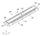
도 1은 본 실시예에 따른 커넥터를 나타낸 사시도,
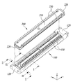
도 2는 도 1의 커넥터를 나타낸 분해도,
도 3은 도 2의 커넥터를 나타낸 I-I 방향 결합 단면도,
도 4는 도 2의 커넥터를 나타낸 Ⅱ-Ⅱ 방향 결합 단면도,
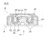
도 5는 도 2의 커넥터를 나타낸 Ⅲ-Ⅲ 방향 결합 단면도,
도 6은 본 실시예의 리셉터클 커넥터를 나타낸 사시도,
도 7은 도 6의 리셉터클 커넥터를 나타낸 분해도,
도 8은 도 6의 주요부인 리셉터클 금구의 일 예를 나타낸 사시도,
도 9는 도 6의 주요부인 리셉터클 금구의 다른 예를 나타낸 사시도,
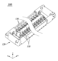
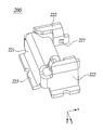
도 10은 본 실시예의 플러그 커넥터를 나타낸 사시도,
도 11은 도 10의 플러그 커넥터를 나타낸 분해도,
도 12는 도 10의 주요부인 플러그 금구를 나타낸 사시도.1 is a perspective view showing a connector according to this embodiment,
Figure 2 is an exploded view showing the connector of Figure 1,
Figure 3 is a cross-sectional view of the II direction of the connector of Figure 2,
4 is a cross-sectional view taken along the direction II-II of the connector of FIG. 2,
5 is a cross-sectional view taken along the III-III direction of the connector of FIG. 2,
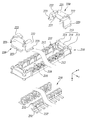
Figure 6 is a perspective view showing the receptacle connector of this embodiment,
Figure 7 is an exploded view showing the receptacle connector of Figure 6,
8 is a perspective view showing an example of a receptacle bracket that is a main part of FIG. 6,
9 is a perspective view showing another example of the main part of the receptacle bracket of FIG. 6,
10 is a perspective view showing a plug connector of this embodiment,
Figure 11 is an exploded view showing the plug connector of Figure 10,
FIG. 12 is a perspective view showing a main part of FIG. 10 as a plug bracket.
본 발명과 본 발명의 실시에 의해 달성되는 기술적 과제는 다음에서 설명하는 바람직한 실시예들에 의해 명확해질 것이다. 이하 첨부된 도면을 참조하여 본 발명의 바람직한 실시예를 상세히 살펴보기로 한다.The technical problems achieved by the present invention and the practice of the present invention will be clarified by the preferred embodiments described below. Hereinafter, exemplary embodiments of the present invention will be described in detail with reference to the accompanying drawings.
후술되는 본 실시예들의 차이는 상호 배타적이지 않은 사항으로 이해되어야 한다. 즉 본 발명의 기술 사상 및 범위를 벗어나지 않으면서, 기재되어 있는 특정 형상, 구조 및 특성은, 일 실시예에 관련하여 다른 실시예로 구현될 수 있으며, 각각의 개시된 실시예 내의 개별 구성요소의 위치 또는 배치는 변경될 수 있음이 이해되어야 하며, 도면에서 유사한 참조부호는 여러 측면에 걸쳐서 동일하거나 유사한 기능을 지칭하며, 제조 원자재, 길이, 면적 및 두께 등과 그 형태는 편의를 위하여 과장되어 표현될 수도 있다. 본 실시예의 설명에 있어서, 전, 후, 상, 하, 제 1, 제 2 등과 같은 표현은 서로 다른 구성에 대한 상대적인 위치, 방향 또는 순서를 나타내는 것으로, 기술적 의의가 반드시 그 사전적 의미에 구속되는 것은 아니라 할 것이다.It should be understood that differences between the embodiments described below are not mutually exclusive. That is, without departing from the spirit and scope of the invention, the specific shapes, structures, and characteristics described may be implemented in other embodiments in relation to one embodiment, and the location of individual components within each disclosed embodiment Or, it should be understood that the arrangement may be changed, and similar reference numerals in the drawings refer to the same or similar functions across various aspects, and the raw material, length, area, and thickness, etc. may be exaggerated for convenience. have. In the description of the present embodiment, the expressions such as before, after, up, down, first, second, etc. indicate relative positions, directions, or orders for different configurations, and the technical significance is necessarily bound to the dictionary meaning. It will not.
도 1은 본 실시예에 따른 커넥터를 나타낸 사시도이고, 도 2는 도 1의 커넥터를 나타낸 분해도이며, 도 3 내지 도 5는 도 2의 커넥터를 나타낸 결합 단면도로서, 각각 I-I 방향, Ⅱ-Ⅱ 방향 및 Ⅲ-Ⅲ 방향의 단면을 도시하였다.1 is a perspective view showing a connector according to the present embodiment, FIG. 2 is an exploded view showing the connector of FIG. 1, and FIGS. 3 to 5 are coupling cross-sectional views showing the connector of FIG. 2, respectively, II direction, II-II direction And Ⅲ-Ⅲ directions.
이들 도면에 도시된 바와 같이 본 실시예의 커넥터는 리셉터클 커넥터(100)와, 리셉터클 커넥터(100)에 접속되는 플러그 커넥터(200)로 구성된다.As shown in these drawings, the connector of this embodiment is composed of a
리셉터클 커넥터(100)는 제 1 기판(10)에 실장되는 제 1 커넥터로서, 절연 소재의 리셉터클 하우징(110)과, 리셉터클 하우징(110)의 강성을 보강하는 리셉터클 금구(120)와, 리셉터클 하우징(110)에 배치되는 다수의 리셉터클 단자(130)를 포함한다.The
리셉터클 하우징(110)은 리셉터클 커넥터(100)의 몸체를 구성하며, 절연 소재의 수지가 사출 성형되어 형성될 수 있다. 리셉터클 금구(120)는 리셉터클 하우징(110)의 양 단부에서 제 1 기판(10)에 솔더링되어 리셉터클 하우징(110)의 강성을 보강하면서 리셉터클 하우징(110)을 제 1 기판(10)에 고정시킨다. 리셉터클 금구(120)는 금속 소재의 플레이트가 프레스 및 벤딩 가공되어 형성될 수 있다. 리셉터클 하우징(110)과 리셉터클 금구(120)는 오버 몰딩(over molding)에 의하여 일체형으로 제조될 수 있다.The
리셉터클 단자(130)는 일 측 단부가 제 1 기판(10)에 접속되고, 타 측 단부가 플러그 커넥터(200)의 접속시 플러그 단자(230)와 접촉되어, 도 3에 도시된 바와 같이, 제 1 기판(10)과 제 2 기판(20)을 전기적으로 연결한다. 리셉터클 단자(130)는 전기 전도성이 우수한 금속 소재의 플레이트가 프레스 및 벤딩 가공되어 형성될 수 있으며, 리셉터클 단자 홀(도 7의 118 참조)에 오버 몰딩되어 일체형으로 제조될 수 있다. As for the
또한, 리셉터클 단자(130)는 제 1 기판(10)에 접속되는 제 1 접속부(131), 제 1 접속부(131)에서 '∩' 형상으로 벤딩되어 리셉터클 하우징(110)에 수용되어 고정되는 제 1 고정부(132)와, 제 1 고정부(132)의 단부에서 '∪' 형상으로 벤딩되는 제 1 베이스부(133)를 포함한다. 제 1 베이스부(133)가 형성하는 내부 공간에 플러그 단자(230)를 수용한다. 제 1 베이스부(133)의 단부에는 내부 공간으로 볼록하게 돌출되는 접촉 돌부(134)가 형성되어 내부 공간에 수용되는 플러그 단자(230)를 접촉시킨다.In addition, the
플러그 커넥터(200)는 제 2 기판(20)에 실장되는 제 2 커넥터로서, 절연 소재의 플러그 하우징(210)과, 플러그 하우징(210)의 강성을 보강하는 플러그 금구(220)와, 플러그 하우징(210)에 배치되는 다수의 플러그 단자(230)를 포함한다.The
플러그 하우징(210)은 플러그 커넥터(200)의 몸체를 구성하며, 절연 소재의 수지가 사출 성형되어 형성될 수 있다. 플러그 금구(220)는 플러그 하우징(210)의 양 단부에서 제 2 기판(20)에 솔더링되어 플러그 하우징(210)의 강성을 보강하면서 플러그 하우징(210)을 제 2 기판(20)에 고정시킨다. 플러그 금구(220)는 금속 소재의 플레이트가 프레스 및 벤딩 가공되어 형성될 수 있다. 또한, 플러그 하우징(210)과 플러그 금구(220)는 오버 몰딩에 의하여 일체형으로 제조될 수 있다.The
플러그 단자(230)는 일 측 단부가 제 2 기판(20)에 접속되고, 타 측 단부가 리셉터클 커넥터(100)의 접속시 리셉터클 단자(130)와 접촉되어, 제 2 기판(20)과 제 1 기판(10)을 전기적으로 연결한다. 플러그 단자(230)는 전도성이 우수한 금속 소재의 플레이트가 프레스 및 벤딩 가공되어 형성될 수 있으며, 플러그 단자 홀(도 11의 218 참조)에 오버 몰딩되어 일체형으로 제조될 수 있다.One end of the
또한, 플러그 단자(230)는 제 2 기판(20)에 접속되는 제 2 접속부(231)와, 제 2 접속부(231)에서 '∪' 형상으로 벤딩되는 제 2 베이스부(232)를 포함한다. 플러그 단자(230)는 제 2 베이스부(232)가 리셉터클 단자(130)의 제 1 베이스부(133) 내부 공간으로 삽입되면서 리셉터클 단자(130)에 접속된다. 제 2 베이스부(232)의 단부 표면에는 접촉 홈부(233)가 오목하게 형성되고, 탄성을 갖는 접촉 돌부(134)가 접촉 홈부(233)에 접촉되면서 리셉터클 단자(130)와 플러그 단자(230)의 전기적 접속이 이루어진다.In addition, the
또한, 제 1 고정부(132)의 단부(또는 제 1 베이스부의 시작부)와 제 2 베이스부(232)의 단부에는 서로 대응하는 형상의 걸림 돌기(132', 232')가 엇물리도록 형성되어 접촉된 리셉터클 단자(130)와 플러그 단자(230)가 쉽게 분리되지 않도록 한다. In addition, end portions of the first fixing portion 132 (or the beginning portion of the first base portion) and the end portions of the
또한, 본 실시예의 커넥터는 플러그 커넥터(200)가 리셉터클 커넥터(100)에 접속될 때, 접속 과정과 접속 완료의 클릭감을 개선하는 접속 감지부재가 형성된다.In addition, in the connector of the present embodiment, when the
도 4를 참조하면, 제 1 접속 감지부재로서 리셉터클 금구(120)에는 탄성 돌부(125)가 형성된다. 탄성 돌부(125)는 리셉터클 금구(120)의 일부가 절개되어 형성될 수 있으며, 고정편(125-1)과, 고정편(125-1)의 단부가 내측으로 돌출되어 탄성을 가지는 탄성편(125-2)으로 구성될 수 있다. 리셉터클 커넥터(100)와 플러그 커넥터(200)가 접속될 때 탄성편(125-2)은 플러그 금구(220)의 측면을 탄성 가압하게 된다. 따라서, 플러그 금구(220)가 탄성편(125-2)에 접촉될 때 탄성편(125-2)의 탄성에 의하여 탄성편(125-2)과 플러그 금구(220) 사이에 마찰력이 작용하여, 작업자는 마찰력에 따른 클릭감으로 리셉터클 커넥터(100)와 플러그 커넥터(200)의 접속을 감지하게 된다.Referring to FIG. 4, an
또한, 도 5를 참조하면, 제 2 접속 감지부재로서 리셉터클 금구(120)에는 고정 돌기(127)가 형성되고, 플러그 금구(220)에는 고정 돌기(127)가 수용되는 돌기 홈부(227)가 형성된다. 고정 돌기(127)는 리셉터클 커넥터(100)와 플러그 커넥터(200)가 접속될 때 플러그 금구(220)의 측면을 가압하고, 접속이 완료될 때 돌기 홈부(227)에 안착 및 수용된다. 따라서, 고정 돌기(127)가 플러그 금구(220) 표면에 접촉될 때 강한 마찰력이 작용하고, 고정 돌기(127)가 돌기 홈부(227)에 안착되는 순간 마찰력이 사라지므로, 작업자는 마찰력 해제에 따른 클릭감으로 리셉터클 커넥터(100)와 플러그 커넥터(200)의 접속이 완료되었음을 쉽게 감지하게 된다.In addition, referring to FIG. 5, a fixing
따라서 본 실시예의 커넥터는 제 1 및 제 2 접속 감지부재에서 작업자에게 클릭감을 제공하여 커넥터 결합 과정에서 접속 오류를 방지할 수 있다.Therefore, the connector of the present embodiment can provide a click feeling to the operator in the first and second connection sensing members, thereby preventing a connection error in the connector coupling process.
도 6은 본 실시예의 리셉터클 커넥터를 나타낸 사시도이고, 도 7은 도 6의 리셉터클 커넥터를 나타낸 분해도이며, 도 8은 도 6의 주요부인 리셉터클 금구의 일 예를 나타낸 사시도이고, 도 9는 도 6의 주요부인 리셉터클 금구의 다른 예를 나타낸 사시도이다.6 is a perspective view showing the receptacle connector of the present embodiment, FIG. 7 is an exploded view showing the receptacle connector of FIG. 6, FIG. 8 is a perspective view showing an example of a receptacle bracket that is a main part of FIG. 6, and FIG. 9 is a view of FIG. It is a perspective view showing another example of the main part receptacle bracket.
도 6 및 도 7에 도시된 바와 같이, 본 실시예의 리셉터클 커넥터(100)에 있어서, 리셉터클 하우징(110)은 소정의 폭과 길이를 갖는 직육면체 형상을 이루면서, 제 1 바닥부(111)와, 제 1 바닥부(111)의 길이 방향 양 측 가장자리를 따라 돌출 형성되는 한 쌍의 제 1 측벽부(112)와, 제 1 바닥부(111)의 폭 방향 양 측 가장자리를 따라 돌출 형성되면서 제 1 측벽부(112)의 양 단부를 연결하는 한 쌍의 제 2 측벽부(113)와, 한 쌍의 제 1 측벽부(112) 및 한 쌍의 제 2 측벽부(113)와 이격되면서 제 1 바닥부(111)의 중앙에서 길이 방향을 따라 돌출 형성되는 중앙 돌출부(116)와, 중앙 돌출부(116), 한 쌍의 제 1 측벽부(112) 및 한 쌍의 제 2 측벽부(113) 사이에서 오목하게 형성되는 제 1 접속 홈부(117)를 포함한다. 제 1 바닥부(111), 제 1 측벽부(112), 제 2 측벽부(113) 및 중앙 돌출부(116)는 사출 성형으로 일체로 연결된다.6 and 7, in the
제 1 측벽부(112)는 소정의 두께를 갖는 벽체로서 제 1 바닥부(111)의 길이 방향 양 측부에서 서로 마주하는 대칭 형상을 이룬다. The first
제 2 측벽부(113)는 소정의 두께를 갖는 벽체로서 제 1 바닥부(111)의 폭 방향 양 측부에서 서로 마주하는 대칭 형상을 이룬다. 또한, 제 2 측벽부(113)는 폭 방향으로 벽체를 이루는 제 1 본체부(114)와, 제 1 본체부(114)의 양 단부에서 내측의 길이 방향으로 연장되어 제 1 측벽부(112)에 연결되는 한 쌍의 제 1 연장부(115)로 구성된다.The second
중앙 돌출부(116)는 소정의 두께를 갖는 벽체로서 길이 방향을 따라 돌출 형성되며, 길이 방향의 양측은 돌출 단부(116')를 형성한다.The
제 1 접속 홈부(117)는 플러그 커넥터(200)의 플러그 하우징(210)을 수용하여 리셉터클 커넥터(100)와 플러그 커넥터(200)를 결합시키며, 중앙 돌출부(116)와 제 1 측벽부(112) 및 제 2 측벽부(113) 사이에서 트랙 또는 사각 형상으로 형성된다.The first
또한, 중앙 돌출부(116), 제 1 바닥부(111) 및 한 쌍의 제 1 측벽부(112)를 따라 오목하게 함몰되거나 관통되는 리셉터클 단자 홀(118)이 형성된다. 리셉터클 단자 홀(118)은 길이 방향을 따라 소정 간격을 이루면서 다수개 형성되며, 각 리셉터클 단자 홀(118)은 리셉터클 단자(130)를 수용한다.In addition, a
리셉터클 금구(120)는 리셉터클 하우징(110)의 양 단부, 즉, 제 2 측벽부(113)와 중앙 돌출부(116)의 돌출 단부(116')에 결합되어 리셉터클 하우징(110)의 강성을 보강하며, 리셉터클 하우징(110)을 제 1 기판(10)에 고정시킨다.The
도 8을 참조하면, 리셉터클 금구(120)는 제 1 연결부(121)와, 제 1 연결부(121)의 외측 단부에서 상측으로 연장되어 제 2 측벽부(113)의 제 1 본체부(114)에 결합되는 제 1 보강부(122)와, 제 1 연결부(121)의 양측 단부에서 상측으로 연장되어 제 2 측벽부(113)의 제 1 연장부(115)에 결합되는 한 쌍의 제 2 보강부(123)와, 제 1 연결부(121)의 내측 단부에서 상측으로 연장되어 중앙 돌출부(116)의 돌출 단부(116')에 결합되는 제 3 보강부(124)를 포함한다. 제 1 보강부(122)와 제 2 보강부(123)의 단부에는 제 1 솔더링부(129)가 형성된다. Referring to FIG. 8, the
리셉터클 금구(120)는 제 1 내지 제 3 보강부(122,123,124)가 각각 제 2 측벽부(113)의 제 1 본체부(114)와 제 1 연장부(115), 중앙 돌출부(116)의 돌출 단부(116')를 감싸면서 결합되어 이들의 강성을 보강하고, 제 1 솔더링부(129)가 제 1 기판(10)에 솔더링되면서 리셉터클 하우징(110)을 고정한다.In the
제 1 내지 제 3 보강부(124)는 제 1 연결부(121)의 단부에서 '∩' 형상으로 벤딩 및 연장되어 형성될 수 있으며, 제 1 보강부(122) 및 제 2 보강부(123)는 제 1 연결부(121)의 단부 내측에서 외측 방향으로 벤딩되거나 제 1 연결부(121)의 단부 외측에서 내측 방향으로 벤딩될 수 있다.The first to third reinforcing
또한, 제 2 보강부(123)는 플러그 커넥터(200)의 접속을 알리는 탄성 돌부(125)를 포함한다. 탄성 돌부(125)는 제 1 연장부(115) 내면에 접하는 일부가 절개되어 형성되고, 제 1 연결부(121)에 연결되는 일 측의 고정편(125-1)과 내측으로 볼록하게 돌출되는 타 측 단부의 탄성편(125-2)으로 구성된다. 고정편(125-1)은 제 1 연결부(121)에 연결되어 고정되고, 탄성편(125-2)은 고정편(125-1)에 지지되면서 제 2 보강부(123)와 분리되어 탄성을 갖는다. 탄성 돌부(125)는 리셉터클 커넥터(100)에 플러그 커넥터(200)가 접속될 때 탄성편(125-2)이 플러그 금구(220)의 외 측면을 탄성 가압한다(도 4 참조).In addition, the second reinforcing
또한, 제 3 보강부(124)는 돌출 단부(116')의 측면을 보강하는 측면 보강부(126)와, 플러그 커넥터(200)의 접속 완료를 알리는 고정 돌기(127)를 포함한다.In addition, the third reinforcing
측면 보강부(126)는 제 3 보강부(124)가 외측 단부면의 양 측부에서 내측, 즉, 중앙 돌출부(116)의 돌출 단부 방향(-x 방향)으로 벤딩되어 형성된다. 측면 보강부(126)는 리셉터클 하우징(110)의 돌출 단부(116') 양 측면에 결합되어 돌출 단부(116')의 측면 강성을 보강한다. 이때, 제 3 보강부(124)의 외측 단부면에는 수지 홀(128)이 형성되어 오버 몰딩 공정에서 수지가 쉽게 유입될 수 있도록 한다.The
고정 돌기(127)는 측면 보강부(126) 표면에서 외측으로 돌출 형성된다. 플러그 금구(220)의 내 측면에는 고정 돌기(127)에 대응하는 홈 형상의 돌기 홈부(227)가 형성된다. 고정 돌기(127)는 리셉터클 커넥터(100)에 플러그 커넥터(200)가 접속될 때 플러그 금구(220)의 내 측면을 가압하고, 접속이 완료될 때 플러그 금구(220)의 돌기 홈부(227)에 안착 및 수용된다(도 5 참조).The fixing
이와 같이 본 실시예의 리셉터클 커넥터(100)는 탄성 돌부(125)와 고정 돌기(127)의 두 위치에서 플러그 커넥터(200)의 접속을 감지하고, 커넥터의 접속에 대한 클릭감을 향상시킬 수 있다. 본 실시예의 설명에 있어서, 리셉터클 금구(120)에 고정 돌기(127)가 형성되고, 플러그 금구(220)에 돌기 홈부(227)가 형성되는 구성을 예시하였으나, 리셉터클 금구(120)에 돌기 홈부가 형성되고, 플러그 금구(220)에 고정 돌기가 형성되는 구성도 당연하다 할 것이다.As described above, the
한편, 도 9를 참조하면, 다른 실시예에 따른 리셉터클 금구(120)에 있어서, 측면 보강부(126)는 제 3 보강부(124)의 상면 양 측부에서 직접 하측(-z 방향)으로 벤딩되어 형성된다. 이때, 제 3 보강부(124)의 외 측부는 개방되어 이중 사출시 사출물이 제 3 보강부(124)의 하부 공간으로 쉽게 유입될 수 있다.On the other hand, referring to Figure 9, in the
도 10은 본 실시예의 플러그를 나타낸 저면 사시도이고, 도 11은 도 10의 플러그를 나타낸 분해도이며, 도 12는 도 10의 주요부인 플러그 금구를 나타낸 사시도이다.FIG. 10 is a bottom perspective view showing the plug of this embodiment, FIG. 11 is an exploded view showing the plug of FIG. 10, and FIG. 12 is a perspective view showing the main part of the plug bracket of FIG. 10.
도 10 및 도 11에 도시된 바와 같이, 본 실시예의 플러그 커넥터(200)에 있어서, 플러그 하우징(210)은 소정의 폭과 길이를 갖는 직육면체 형상을 이루면서, 제 2 바닥부(211)와, 제 2 바닥부(211)의 길이 방향 양 측 가장자리를 따라 돌출 형성되는 한 쌍의 제 3 측벽부(212)와, 제 2 바닥부(211)의 폭 방향 양 측 가장자리를 따라 돌출 형성되면서 제 3 측벽부(212)의 양 단부를 연결하는 한 쌍의 제 4 측벽부(213)를 포함한다. 제 2 바닥부(211), 제 3 측벽부(212) 및 제 4 측벽부(213)는 사출 성형으로 일체로 연결된다.10 and 11, in the
제 3 측벽부(212) 및 제 4 측벽부(213)는 소정의 두께를 갖는 벽체로서 제 2 바닥부(211)의 길이 방향 및 폭 방향 양 측부에서 서로 마주하는 대칭 형상을 이루면서 서로 연결된다. 또한, 제 4 측벽부(213)는 폭 방향으로 벽체를 이루는 제 2 본체부(214)와, 제 2 본체부(214)의 양 단부에서 내측의 길이 방향으로 연장되어 제 3 측벽부(212)에 연결되는 한 쌍의 제 2 연장부(215)로 구성된다.The third
한 쌍의 제 3 측벽부(212) 및 한 쌍의 제 4 측벽부(213)는 서로 연결되면서 리셉터클 하우징(110)의 제 1 접속 홈부(117)에 대응하는 트랙 또는 사각 형상을 이루고, 그 내부에 리셉터클 하우징(110)의 중앙 돌출부(116)를 수용하는 제 2 접속 홈부(216)를 형성한다. 따라서 리셉터클 커넥터(100)와 플러그 커넥터(200)가 결합될 때, 리셉터클 하우징(110)의 제 1 접속 홈부(117)에는 플러그 하우징(210)의 제 3 측벽부(212) 및 제 4 측벽부(213)가 삽입되고, 동시에 플러그 하우징(210)의 제 2 접속 홈부(216)에는 리셉터클 하우징(110)의 중앙 돌출부(116)가 삽입된다.The pair of third
또한, 제 3 측벽부(212)는 오목하게 함몰되거나 관통되는 플러그 단자 홀(218)이 형성된다. 플러그 단자 홀(218)은 길이 방향을 따라 소정 간격을 이루면서 다수개 형성되며, 각 플러그 단자 홀(218)은 플러그 단자(230)를 수용한다.In addition, the third
플러그 금구(220)는 플러그 하우징(210)의 양 단부, 즉, 제 4 측벽부(213)에 결합되어 플러그 하우징의 강성을 보강하고, 플러그 하우징(210)을 제 2 기판(20)에 고정시킨다.The
도 12를 참조하면, 플러그 금구(220)는 제 4 측벽부(213)의 제 2 본체부(214)에 결합되는 제 4 보강부(221)와, 제 4 보강부(221)의 양측 단부에서 외측으로 연결되어 제 4 측벽부(213)의 제 2 연장부(215)에 결합되는 한 쌍의 제 5 보강부(222)를 포함한다. 제 4 보강부(221) 및 제 5 보강부(222)는 '∩' 형상으로 벤딩되어 제 2 본체부(214) 및 제 2 연장부(215)의 표면을 감싸면서 결합될 수 있고, 제 2 본체부 (214) 및 제 2 연장부(215)의 외면에서 내면을 따라 벤딩되거나 내면에서 외면을 따라 벤딩될 수 있다.Referring to FIG. 12, the
제 4 보강부(221) 및 제 5 보강부(222)는 제 2 기판(20)에 솔더링되기 위하여 하단부가 외측 또는 내측의 수평으로 벤딩되는 제 2 솔더링부(223)를 각각 포함한다. 제 2 솔더링부(223)는 제 4 보강부(221) 및 제 5 보강부(222)의 내외측 하단부에 모두 형성될 수 있다.The fourth reinforcing
또한, 제 5 보강부(222)는 리셉터클 커넥터(100)의 접속 완료를 알리는 돌기 홈부(227)를 더 포함한다. 돌기 홈부(227)는 리셉터클 금구(120)의 고정 돌기(127)에 대응하는 위치로서 제 2 연장부(215)의 내면에 접하는 제 5 보강부(222)에 형성된다. 돌기 홈부(227)는 리셉터클 커넥터(100)와 플러그 커넥터(200)의 접속 완료시 고정 돌기(127)를 수용시켜 작업자가 커넥터의 접속이 완료되었음을 쉽게 감지할 수 있도록 한다.In addition, the fifth reinforcing
이상과 같이 본 발명의 예시적인 실시예가 도시되어 설명되었지만, 다양한 변형과 다른 실시예가 본 분야의 숙련된 기술자들에 의해 행해질 수 있다. 이러한 변형과 다른 실시예들은 첨부된 청구범위에 모두 고려되고 포함되어 본 발명의 진정한 취지 및 범위를 벗어나지 않는다 할 것이다.As described above, exemplary embodiments of the present invention are shown and described, but various modifications and other embodiments may be performed by those skilled in the art. These modifications and other embodiments are all to be considered and included in the appended claims will not depart from the true spirit and scope of the invention.
100 : 리셉터클 커넥터
110 : 리셉터클 하우징
111 : 제 1 바닥부
112 : 제 1 측벽부
113 : 제 2 측벽부
114 : 제 1 본체부
115 : 제 1 연장부
116 : 중앙 돌출부
117 : 제 1 접속 홈부
118 : 리셉터클 단자 홀
120 : 리셉터클 금구
121 : 제 1 연결부
122 : 제 1 보강부
123 : 제 2 보강부
124 : 제 3 보강부
125 : 탄성 돌부
126 : 측면 보강부
127 : 고정 돌기
130 : 리셉터클 단자
200 : 플러그 커넥터
210 : 플러그 하우징
211 : 제 2 바닥부
212 : 제 3 측벽부
213 : 제 4 측벽부
214 : 제 2 본체부
215 : 제 2 연장부
216 : 제 2 접속 홈부
218 : 플러그 단자 홀
220 : 플러그 금구
221 : 제 4 보강부
222 : 제 5 보강부
223 : 제 2 솔더링부
227 : 돌기 홈부
230 : 플러그 단자100: receptacle connector
110: receptacle housing 111: first bottom
112: first side wall portion 113: second side wall portion
114: first body portion 115: first extension
116: central projection 117: first connection groove
118: Receptacle terminal hole
120: receptacle bracket 121: first connection
122: first reinforcement 123: second reinforcement
124: third reinforcing part 125: elastic protrusion
126: side reinforcement 127: fixed projection
130: receptacle terminal
200: plug connector
210: plug housing 211: second bottom
212: 3rd side wall part 213: 4th side wall part
214: second body portion 215: second extension
216: second connection groove 218: plug terminal hole
220: plug bracket 221: fourth reinforcement
222: 5th reinforcement part 223: 2nd soldering part
227: projection groove
230: plug terminal
Claims (8)
기판에 솔더링되면서 상기 제 2 측벽부 및 상기 중앙 돌출부의 돌출 단부에 결합되는 리셉터클 금구; 및
상기 리셉터클 하우징에 형성된 리셉터클 단자 홀에 수용되는 리셉터클 단자;를 포함하고,
상기 리셉터클 금구는,
상기 플러그 금구를 탄성 가압하여 접속의 클릭감을 제공하는 제 1 접속 감지부재와, 상기 플러그 금구를 가압 해제하여 접속의 클릭감을 제공하는 제 2 접속 감지부재를 구비하는 것을 특징으로 하는 리셉터클 커넥터.A first sidewall portion protruding along opposite side edges of the bottom portion, a second sidewall portion protruding along the other opposite side edges of the bottom portion and connected to the first sidewall portion, and a center of the bottom portion A receptacle housing having a central protrusion formed protrudingly at and a connection groove formed between the first sidewall portion, the second sidewall portion and the central protrusion;
A receptacle bracket coupled to a protruding end portion of the second side wall portion and the central protrusion portion while being soldered to a substrate; And
Including; a receptacle terminal accommodated in the receptacle terminal hole formed in the receptacle housing;
The receptacle bracket,
And a first connection sensing member for elastically pressing the plug bracket to provide a click feeling of the connection, and a second connection sensing member for releasing the plug bracket to provide a click feeling for the connection.
상기 제 2 측벽부는,
폭 방향의 본체부와 상기 본체부의 양 단부에서 길이 방향으로 연장되어 상기 제 1 측벽부에 연결되는 연장부로 이루어지고,
상기 리셉터클 금구는,
연결부와, 상기 연결부의 일 측 단부에서 상측으로 연장되어 상기 본체부에 결합되는 제 1 보강부와, 상기 연결부의 양 측 단부에서 상측으로 연장되어 상기 연장부에 결합되는 한 쌍의 제 2 보강부와, 상기 제 1 보강부와 마주하는 연결부의 타 측 단부에서 상측으로 연장되어 상기 돌출 단부에 결합되는 제 3 보강부로 이루어지는 것을 특징으로 하는 리셉터클 커넥터.According to claim 1,
The second side wall portion,
It consists of a body portion in the width direction and an extension portion extending in the longitudinal direction from both ends of the body portion and connected to the first side wall portion,
The receptacle bracket,
A connecting portion, a first reinforcing portion extending upwardly from one end of the connecting portion to be coupled to the main body portion, and a pair of second reinforcing portions extending upwardly from both ends of the connecting portion to be coupled to the extending portion And a third reinforcing portion extending from the other end of the connecting portion facing the first reinforcing portion upwards and coupled to the protruding end.
상기 제 2 보강부의 일부가 절개되어 형성되고, 상기 연결부에 연결되는 고정편과, 상기 고정편의 단부에서 내측으로 돌출되어 상기 플러그 금구의 외 측면을 탄성 가압하는 탄성편으로 이루어지는 것을 특징으로 하는 리셉터클 커넥터.The method of claim 2, wherein the first connection sensing member,
A receptacle connector, characterized in that a part of the second reinforcing part is formed by being cut out, and a fixed piece connected to the connection part and an elastic piece projecting inward from an end of the fixed piece to elastically press the outer side surface of the plug bracket. .
상기 돌출 단부의 양 측면에 결합되는 측면 보강부를 포함하는 것을 특징으로 하는 리셉터클 커넥터.According to claim 2, The third reinforcement,
Receptacle connector, characterized in that it comprises a side reinforcement coupled to both sides of the protruding end.
측면 보강부의 외면에 형성되고, 상기 플러그 금구의 표면에 형성되는 접속 감지부재와 형합하는 고정 돌기 또는 돌기 홈부인 것을 특징으로 하는 리셉터클 커넥터.The method of claim 4, wherein the second connection sensing member,
It is formed on the outer surface of the side reinforcement, the receptacle connector, characterized in that the fixed projection or projection groove portion to match the connection detection member formed on the surface of the plug bracket.
상기 제 3 보강부의 외측 단부면 양 측부에서 상기 돌출 단부 방향으로 벤딩되어 형성되는 것을 특징으로 하는 리셉터클 커넥터.According to claim 4, The side reinforcement,
Receptacle connector, characterized in that formed by bending in the direction of the protruding end from both sides of the outer end surface of the third reinforcement.
상기 외측 단부면에 수지가 유입되는 수지 홀이 형성되는 것을 특징으로 하는 리셉터클 커넥터.The method of claim 6, wherein the third reinforcement,
A receptacle connector, characterized in that a resin hole through which resin is introduced is formed on the outer end surface.
상기 제 3 보강부의 상면 양 측부에서 하측으로 벤딩되어 형성되는 것을 특징으로 하는 리셉터클 커넥터.
According to claim 4, The side reinforcement,
A receptacle connector, characterized in that it is formed by bending from both sides of the upper surface of the third reinforcement portion to the lower side.
Priority Applications (5)
| Application Number | Priority Date | Filing Date | Title |
|---|---|---|---|
| KR1020180170312A KR102659117B1 (en) | 2018-12-27 | Receptacle connector | |
| US17/413,587 US20220052468A1 (en) | 2018-12-27 | 2019-12-24 | Receptacle connector |
| CN201980085872.3A CN113228424B (en) | 2018-12-27 | 2019-12-24 | Socket connector |
| PCT/US2019/068455 WO2020139875A1 (en) | 2018-12-27 | 2019-12-24 | Receptacle connector |
| JP2021526306A JP7198924B2 (en) | 2018-12-27 | 2019-12-24 | receptacle connector |
Applications Claiming Priority (1)
| Application Number | Priority Date | Filing Date | Title |
|---|---|---|---|
| KR1020180170312A KR102659117B1 (en) | 2018-12-27 | Receptacle connector |
Publications (2)
| Publication Number | Publication Date |
|---|---|
| KR20200080647A true KR20200080647A (en) | 2020-07-07 |
| KR102659117B1 KR102659117B1 (en) | 2024-04-18 |
Family
ID=
Citations (1)
| Publication number | Priority date | Publication date | Assignee | Title |
|---|---|---|---|---|
| KR20150027710A (en) | 2013-09-04 | 2015-03-12 | 몰렉스 인코포레이티드 | Board to board connector |
Patent Citations (1)
| Publication number | Priority date | Publication date | Assignee | Title |
|---|---|---|---|---|
| KR20150027710A (en) | 2013-09-04 | 2015-03-12 | 몰렉스 인코포레이티드 | Board to board connector |
Also Published As
| Publication number | Publication date |
|---|---|
| WO2020139875A1 (en) | 2020-07-02 |
| CN113228424B (en) | 2024-04-02 |
| JP7198924B2 (en) | 2023-01-04 |
| CN113228424A (en) | 2021-08-06 |
| US20220052468A1 (en) | 2022-02-17 |
| JP2022507405A (en) | 2022-01-18 |
Similar Documents
| Publication | Publication Date | Title |
|---|---|---|
| TWI744740B (en) | Socket connector, plug connector and board-to-board connector with the same | |
| US10756466B2 (en) | Connector | |
| US11355882B2 (en) | Board-to-board connector | |
| KR101020389B1 (en) | Connector and connector connecting body | |
| JP7198924B2 (en) | receptacle connector | |
| US7845987B2 (en) | Electrical connector with plug connector and receptacle connector | |
| US8113884B2 (en) | Connector | |
| US7794253B2 (en) | Coaxial connector with a new type of contact | |
| US9461388B2 (en) | Electrical connector having improved tongue portion | |
| JP7445703B2 (en) | connector | |
| KR20080079181A (en) | Electric connector for circuit board and combination connector with thereof | |
| JP7208115B2 (en) | connector | |
| KR20190085601A (en) | Plug connector | |
| KR20200008840A (en) | receptacle connector | |
| KR102659117B1 (en) | Receptacle connector | |
| JP7403614B2 (en) | connector | |
| JPH0434880A (en) | Connector | |
| US7314381B2 (en) | Electric component having connector attached to case via seal member | |
| KR102479629B1 (en) | Connector Apparatus for Surface Mount | |
| KR102319024B1 (en) | Socket terminal and socket connector comprising the same | |
| KR102165739B1 (en) | Hold down of connector and connector including the same | |
| KR20210029320A (en) | Fpcb-to-board connector | |
| KR20210064850A (en) | Plug Connector |
Legal Events
| Date | Code | Title | Description |
|---|---|---|---|
| A201 | Request for examination | ||
| E902 | Notification of reason for refusal | ||
| E701 | Decision to grant or registration of patent right |