KR20200080298A - Belt drive monitoring system - Google Patents
Belt drive monitoring system Download PDFInfo
- Publication number
- KR20200080298A KR20200080298A KR1020207015808A KR20207015808A KR20200080298A KR 20200080298 A KR20200080298 A KR 20200080298A KR 1020207015808 A KR1020207015808 A KR 1020207015808A KR 20207015808 A KR20207015808 A KR 20207015808A KR 20200080298 A KR20200080298 A KR 20200080298A
- Authority
- KR
- South Korea
- Prior art keywords
- sensor
- data
- driver
- monitoring system
- magnetic field
- Prior art date
Links
- 238000012544 monitoring process Methods 0.000 title claims abstract description 20
- 230000005355 Hall effect Effects 0.000 claims description 14
- 238000000034 method Methods 0.000 claims description 6
- 238000004364 calculation method Methods 0.000 description 6
- 238000005070 sampling Methods 0.000 description 6
- 238000013461 design Methods 0.000 description 4
- 230000005540 biological transmission Effects 0.000 description 3
- 230000009977 dual effect Effects 0.000 description 3
- 230000000007 visual effect Effects 0.000 description 3
- 238000006243 chemical reaction Methods 0.000 description 2
- 238000007689 inspection Methods 0.000 description 2
- 230000003068 static effect Effects 0.000 description 2
- 238000012546 transfer Methods 0.000 description 2
- 238000013459 approach Methods 0.000 description 1
- 238000004891 communication Methods 0.000 description 1
- 238000010276 construction Methods 0.000 description 1
- 238000013524 data verification Methods 0.000 description 1
- 238000010586 diagram Methods 0.000 description 1
- 238000009434 installation Methods 0.000 description 1
- 230000007774 longterm Effects 0.000 description 1
- 238000012423 maintenance Methods 0.000 description 1
- 238000005259 measurement Methods 0.000 description 1
- 238000012986 modification Methods 0.000 description 1
- 230000004048 modification Effects 0.000 description 1
- 210000001747 pupil Anatomy 0.000 description 1
- 230000002787 reinforcement Effects 0.000 description 1
- 238000005096 rolling process Methods 0.000 description 1
- 230000001360 synchronised effect Effects 0.000 description 1
- 230000002618 waking effect Effects 0.000 description 1
Images

Classifications
-
- G—PHYSICS
- G01—MEASURING; TESTING
- G01M—TESTING STATIC OR DYNAMIC BALANCE OF MACHINES OR STRUCTURES; TESTING OF STRUCTURES OR APPARATUS, NOT OTHERWISE PROVIDED FOR
- G01M13/00—Testing of machine parts
- G01M13/02—Gearings; Transmission mechanisms
- G01M13/023—Power-transmitting endless elements, e.g. belts or chains
-
- F—MECHANICAL ENGINEERING; LIGHTING; HEATING; WEAPONS; BLASTING
- F02—COMBUSTION ENGINES; HOT-GAS OR COMBUSTION-PRODUCT ENGINE PLANTS
- F02B—INTERNAL-COMBUSTION PISTON ENGINES; COMBUSTION ENGINES IN GENERAL
- F02B77/00—Component parts, details or accessories, not otherwise provided for
- F02B77/08—Safety, indicating, or supervising devices
- F02B77/081—Safety, indicating, or supervising devices relating to endless members
-
- F—MECHANICAL ENGINEERING; LIGHTING; HEATING; WEAPONS; BLASTING
- F16—ENGINEERING ELEMENTS AND UNITS; GENERAL MEASURES FOR PRODUCING AND MAINTAINING EFFECTIVE FUNCTIONING OF MACHINES OR INSTALLATIONS; THERMAL INSULATION IN GENERAL
- F16H—GEARING
- F16H7/00—Gearings for conveying rotary motion by endless flexible members
- F16H7/02—Gearings for conveying rotary motion by endless flexible members with belts; with V-belts
-
- B—PERFORMING OPERATIONS; TRANSPORTING
- B65—CONVEYING; PACKING; STORING; HANDLING THIN OR FILAMENTARY MATERIAL
- B65G—TRANSPORT OR STORAGE DEVICES, e.g. CONVEYORS FOR LOADING OR TIPPING, SHOP CONVEYOR SYSTEMS OR PNEUMATIC TUBE CONVEYORS
- B65G43/00—Control devices, e.g. for safety, warning or fault-correcting
- B65G43/02—Control devices, e.g. for safety, warning or fault-correcting detecting dangerous physical condition of load carriers, e.g. for interrupting the drive in the event of overheating
Landscapes
- Engineering & Computer Science (AREA)
- General Engineering & Computer Science (AREA)
- Mechanical Engineering (AREA)
- Physics & Mathematics (AREA)
- General Physics & Mathematics (AREA)
- Chemical & Material Sciences (AREA)
- Combustion & Propulsion (AREA)
- Arrangements For Transmission Of Measured Signals (AREA)
- Control Of Conveyors (AREA)
- Geophysics And Detection Of Objects (AREA)
Abstract
벨트 구동기 모니터링 시스템이, 구동자 및 종동자로서, 무단 부재에 의해 연결되는 것인, 구동자 및 종동자, 상기 구동자에 부착되는, 자기장을 갖는 제1 자성 부재, 상기 종동자에 부착되는, 자기장을 갖는 제2 자성 부재, 상기 제1 자성 부재의 통과에 의해 야기되는 변화하는 자기장을 검출하도록 배치되는 제1 센서, 상기 제2 자성 부재의 통과에 의해 야기되는 변화하는 자기장을 검출하도록 배치되는 제2 센서, 상기 제1 센서로부터의 제1 데이터 신호를 수신기에 무선으로 전송하도록 구성되는 제1 송신기 및 상기 제2 센서로부터의 제2 데이터 신호를 수신기에 무선으로 전송하도록 구성되는 제2 송신기, 그리고 시스템 파라미터가 그에 의해 계산되며 그리고 사용자에게 제공되도록, 상기 데이터 신호를 조작하도록 구성되는 상기 수신기를 포함한다. The belt drive monitoring system, as a driver and a follower, connected by an endless member, a driver and a follower, a first magnetic member having a magnetic field attached to the driver, attached to the follower, A second magnetic member having a magnetic field, a first sensor arranged to detect a changing magnetic field caused by passage of the first magnetic member, and a first sensor arranged to detect a changing magnetic field caused by passage of the second magnetic member A second sensor, a first transmitter configured to wirelessly transmit a first data signal from the first sensor to a receiver, and a second transmitter configured to wirelessly transmit a second data signal from the second sensor to a receiver, And the receiver configured to manipulate the data signal so that system parameters are calculated and provided to the user.
Description
본 발명은, 벨트 구동기 모니터링 시스템에 관한 것으로, 더욱 구체적으로, 시스템 작동 상태를 결정하기 위한 데이터 신호의 무선 전송 및 비-접촉 센서들을 포함하는, 벨트 구동기 모니터링 시스템에 관한 것이다. The present invention relates to a belt drive monitoring system, and more particularly, to a belt drive monitoring system, including wireless transmission and non-contact sensors of a data signal to determine a system operating condition.
벨트 구동기들이, 성능 및 비용 이점으로 인해, 상당한 수의 문제가 있는 롤러 체인 구동기들을 대체하고 있다. 롤러 체인 구동기들을 대체하기 위한 벨트 구동기들을 설계할 때, 전통적인 구동기 설계 절차는, 필요한 용량보다 큰 구동기들을 생성할 수 있을 것이다. 실제 작동 부하가 알려지거나 또는 알려지지 않을 수도 있기 때문에, 뒤따르는 3가지 접근법이, 적절한 설계 부하를 결정하기 위해 사용된다: 이용 가능할 때 실제 부하를 사용함; 측정과 더불어 하중을 추정함; 구동기 설계 부하를 계산하기 위해 기존 롤러 체인 구동기의 정격 출력을 사용함. 과도한 크기의 벨트 구동기들을 방지하기 위해, 설계는, 실제 시스템 작동 부하에 기초해야 하며, 추정 기술은, 용량의 손실로 이어진다. Belt drives, due to performance and cost advantages, are replacing a significant number of problematic roller chain drives. When designing belt drivers to replace roller chain drivers, the traditional driver design procedure will be able to produce drivers larger than the required capacity. Since the actual operating load may or may not be known, the following three approaches are used to determine the appropriate design load: use the actual load when available; Estimating load with measurement; To calculate the actuator design load, the rated power of the existing roller chain actuator is used. To avoid oversized belt drives, the design must be based on actual system operating loads, and the estimation technique leads to a loss of capacity.
벨트 구동기들은 흔히, 접근하기 어렵다. 벨트 및 구동기들을 모니터링하는 것은, 불편하며 그리고 많은 비용이 든다. 방호체가 제거되어야만 하고, 기계 가동 중지 시간이 초래되며, 검사가, 벨트 상태에 관한 시각적 단서로 제한된다. 더불어, 이러한 벨트 구동기들은, 검사가 방해되는, 원격 개소에 위치하게 될 수 있을 것이다. 벨트 및 벨트 구동기 성능 특성을 탐지하기 위한 편리한 수단이, 두드러진 고장을 표시하고, 서비스 수명을 결정하며, 그리고 유지보수 일정을 수립하는데, 유용할 수 있을 것이다.Belt drives are often difficult to access. Monitoring belts and actuators is inconvenient and expensive. The guard must be removed, machine downtime results, and inspection is limited to visual clues to the condition of the belt. In addition, these belt drives may be located in remote locations where inspection is interrupted. A convenient means for detecting belt and belt drive performance characteristics may be useful for indicating prominent failures, determining service life, and scheduling maintenance.
종래기술의 대표적인 것이, 하나 이상의 스플라이스 조인트(splice joint), 립 패널(rip panel) 및 강화 코드 손상을 나타내는, 컨베이어 벨트 내의 자기 붕괴들(magnetic disruptions)("이벤트들")을 측정하기 위해 센서를 사용하는, 컨베이어 벨트 모니터링 시스템을 개시하는, 미국 특허 제8,662,290호이다. 시스템은, 립 패널들, 스플라이스들, 및 일반화된 보강 코드 손상을 감지하기 위한, 코일들 또는 홀 효과 센서들을 포함하는, 복수의 감지 구성요소를 포함할 수 있을 것이다. 시스템은 또한, RFID-기반 립 패널들을 구비할 수 있으며, 그리고 다양한 벨트 구성요소를 식별하기 위해 RFID 칩들을 사용할 수 있을 것이다. PLC-기반 제어 시스템이, 이더넷 링크를 통해 상기한 구성요소들과 통신할 수 있을 것이다. 제어 시스템에 의해 수신되는 데이터가, 벨트 마모 및 손상 경향을 도표화하기 위해 그리고 신호 레벨이 미리 정해진 표준을 초과할 때 사용자에게 경보를 제공하기 위해, 사용된다. 시스템은 또한, 임박한 벨트 고장이 예측될 때, 벨트를 정지시킬 수 있을 것이다. PLC-기반 제어 시스템은, 규모 조정 가능하며 그리고 기존의 컨베이어 제어 시스템들 및 시설 전체 모니터링 시스템들 내로 용이하게 통합될 것이다. Representative of the prior art is a sensor for measuring magnetic disruptions (“events”) in a conveyor belt, indicating one or more splice joints, rip panels and reinforced cord damage. US Pat. No. 8,662,290, which discloses a conveyor belt monitoring system, that uses a. The system may include a plurality of sensing components, including coils or hall effect sensors, for detecting lip panels, splices, and generalized reinforcement cord damage. The system can also be equipped with RFID-based lip panels, and use RFID chips to identify various belt components. The PLC-based control system will be able to communicate with the components described above via an Ethernet link. The data received by the control system is used to chart belt wear and damage trends and to alert the user when the signal level exceeds a predetermined standard. The system will also be able to stop the belt when an impending belt failure is predicted. The PLC-based control system is scalable and will be easily integrated into existing conveyor control systems and facility-wide monitoring systems.
필요한 것은, 시스템 작동 상태를 결정하기 위한 데이터 신호의 무선 전송 및 비-접촉 센서들을 포함하는, 벨트 구동기 모니터링 시스템이다. 본 발명은 이러한 필요성을 만족시킨다.What is needed is a belt drive monitoring system, which includes non-contact sensors and wireless transmission of a data signal to determine system operating status. The present invention satisfies this need.
본 발명의 양태가, 시스템 작동 상태를 결정하기 위한 데이터 신호의 무선 전송 및 비-접촉 센서들을 포함하는, 벨트 구동기 모니터링 시스템을 제공하고자 한다. SUMMARY OF THE INVENTION An aspect of the present invention seeks to provide a belt drive monitoring system comprising wireless transmission of data signals and non-contact sensors to determine a system operating condition.
본 발명의 다른 양태들은, 본 발명의 뒤따르는 설명 및 첨부되는 도면에 의해, 부각되거나 명백해질 것이다.Other aspects of the invention will become apparent or apparent by the following description of the invention and the accompanying drawings.
본 발명은, 구동자 및 종동자로서, 무단 부재에 의해 연결되는 것인, 구동자 및 종동자, 상기 구동자에 부착되는, 자기장을 갖는 제1 자성 부재, 상기 종동자에 부착되는, 자기장을 갖는 제2 자성 부재, 상기 제1 자성 부재의 통과에 의해 야기되는 변화하는 자기장을 검출하도록 배치되는 제1 센서, 상기 제2 자성 부재의 통과에 의해 야기되는 변화하는 자기장을 검출하도록 배치되는 제2 센서, 상기 제1 센서로부터의 제1 데이터 신호를 수신기에 무선으로 전송하도록 구성되는 제1 송신기 및 상기 제2 센서로부터의 제2 데이터 신호를 수신기에 무선으로 전송하도록 구성되는 제2 송신기, 그리고 시스템 파라미터가 그에 의해 계산되며 그리고 사용자에게 제공되도록, 상기 데이터 신호를 조작하도록 구성되는 상기 수신기를 포함하는, 벨트 구동기 모니터링 시스템을 포함한다.The present invention provides a driver and a follower, which are connected by an endless member, a driver and a follower, a first magnetic member having a magnetic field attached to the driver, and a magnetic field attached to the follower Having a second magnetic member, a first sensor arranged to detect a changing magnetic field caused by passage of the first magnetic member, a second sensor arranged to detect a changing magnetic field caused by passage of the second magnetic member A sensor, a first transmitter configured to wirelessly transmit a first data signal from the first sensor to a receiver, and a second transmitter configured to wirelessly transmit a second data signal from the second sensor to a receiver, and a system. And a belt drive monitoring system comprising the receiver configured to manipulate the data signal, so that parameters are calculated thereby and provided to the user.
본 명세서에 통합되며 본 명세서의 일부를 형성하는 첨부되는 도면들은, 본 발명의 바람직한 실시예들을 도시하며, 그리고, 상세한 설명과 함께, 본 발명의 원리를 표현하는 역할을 한다.
도 1은 본 발명의 시스템의 일반적인 배열이다.
도 2는 센서 노드(sensor node)의 상세도이다.
도 3은 이중 속도 센서 흐름도이다.
도 4는 서버 흐름도이다.The accompanying drawings, which are incorporated in and form a part of this specification, illustrate preferred embodiments of the invention and, together with the detailed description, serve to express the principles of the invention.
1 is a general arrangement of the system of the present invention.
2 is a detailed view of a sensor node.
3 is a dual speed sensor flow chart.
4 is a server flow chart.
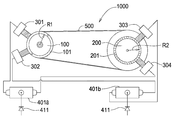
본 발명은, 벨트 구동기를 위한 비-접촉, 무선, 회전 속도 성능 모니터링 시스템을 포함한다. 시스템은, 구동 풀리(100) 및 종동 풀리(200)를 포함한다. 무단 벨트(500)가, 구동 풀리와 종동 풀리 사이에 맞물린다. The present invention includes a non-contact, wireless, rotational speed performance monitoring system for a belt drive. The system includes a
복수의 자석(101)이, 구동 풀리(100)의 둘레 주변에 배열된다. 각 자석은, 각각의 인접한 자석 사이의 사전 결정된 공간 상에 배치된다. 자석들은, 회전축으로부터 반경(R1)에 배치된다. A plurality of
복수의 자석(201)이, 종동 풀리(200)의 둘레 주변에 배열된다. 각 자석(201)은, 각각의 인접한 자석 사이의 사전 결정된 공간 상에 배치된다. 자석들은, 회전축으로부터 반경(R2)에 배치된다. A plurality of
2개의 홀 효과 센서(301, 302)가, 구동 풀리(100) 상의 각 자석(101)의 통과를 검출하도록 배향된다. 2개의 홀 효과 센서(303, 304)가, 종동 풀리(200) 상의 각 자석(201)의 통과를 검출하도록 배향된다. Two
홀 효과 센서들(301, 302, 303, 304)은, IP65 등급 근접 센서들이다.
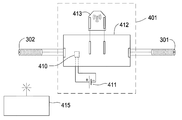
도 2는 센서 회로 수납체의 개략도이다. 센서 회로 수납체들(401a, 401b)은, 동일하며 그리고 회로(412)에 전력을 공급하기 위한 배터리(410) 및/또는 120v 전원(411)을 포함한다. 회로(412)는, 저-전력, 저-비용 응용에 적절한, RF 라디오 모듈(413)에 연결되는 기지국(인텔 칩)을 포함한다. XBee® RF 라디오 모듈(413) 및 인텔 칩의 사용은, 예시이며 그리고 본 발명의 범위를 제한하고자 하는 것이 아니다. 각 홀 효과 센서(301, 302)(303, 304)는, 각 회로 수납체(401) 내의 칩셋(412)에 연결된다. 각 회로(412)는, 연결된 센서들(301, 302)(303, 304)과 함께, 또한 센서 노드로 지칭된다. 2 is a schematic diagram of a sensor circuit housing. The
작동 시, 각 자석(101, 201)으로부터의 자기장이 각각의 개별적인 홀 효과 센서(301, 302)를 주어진 순서대로 통과함에 따라, 전압 신호가 위로 (자기 북극) 또는 아래로 (자기 남극) 당겨지고, 이는 마이크로 컨트롤러의 디지털 입력에 대한 전압 펄스를 트리거한다. 정상 구동 작동 도중에, 펄스들의 시퀀스는, 시각 파형을 나타낸다. 각 센서 노드(401a, 401b)에 부착되는 홀 효과 센서들은, 마이크로 컨트롤러 내로 들어오는 2가지 상이한 파동 형태로 인한 회전 속도 샘플링 오류를 감소시키기 위해, 동기화된 병렬 샘플링을 구비한다. 샘플링 방법은 또한, 홀 효과 센서로부터의 파동 형태 데이터의 다른 것에 대한 무결성이 동일한 특정 시간 및 샘플링 기간에 대한 것임을, 보장한다.In operation, as the magnetic field from each
각 펄스 사이의 시간 간격은, 펌웨어 등록기에 기록되며, 그리고 구동기의 각 샤프트(100, 200)의 회전 속도를 계산하기 위한 연속 평균(rolling average)에 사용된다.The time interval between each pulse is recorded in the firmware register, and is used for a rolling average to calculate the rotational speed of each
유사하게, 배터리(410)로부터의 전압 신호는 마이크로 컨트롤러의 아날로그 입력부에 연결되고, 그로 인해 사용자가 전원의 재충전 또는 충전이 요구되기 이전에 이용 가능한 남아 있는 전력을 측정하는 것을 허용한다.Similarly, the voltage signal from
센서 노드 및 펌웨어 코드는, 배터리가 재충전 또는 교체를 필요로 하기 이전에, 더 긴 작동 간격 동안 배터리 전력을 보존하기 위한 센서 수면 기능을 구비한다. 사용자가 더 많은 영구적인 그리고 신뢰할 수 있는 전원을 요구하는 경우, 120v 전원이 이용 가능하다.The sensor node and firmware code have a sensor sleep function to conserve battery power for longer operating intervals before the battery needs to be recharged or replaced. If the user requires more permanent and reliable power, a 120v power supply is available.
각 홀 효과 센서로부터의 디지털 신호 샘플링 및 원시 데이터 버퍼 저장 이후에, 시스템 회전 속도 및 배터리 계산이, 실행된다. 마이크로 컨트롤러는 이어서, 데이터를, 장소 및 ID 정보에 대한 발신자 MAC 주소 정보와 함께, 패키지화한다. 메시지가, 무선으로 RF 라디오(413)를 통해, 검사 합계 기반 직렬 메시지로서, 개인 영역 네트워크(PAN)를 통해 기지국 수신기 모듈(415)로 전송된다. After sampling the digital signal from each Hall effect sensor and storing the raw data buffer, system rotation speed and battery calculation are performed. The microcontroller then packages the data, along with the sender MAC address information for the place and ID information. The message is wirelessly transmitted via RF radio 413 to the base
각 RF 라디오(413)로부터의 무선 메시지가 기지국(415)에 의해 수신될 때, 기지국은, 데이터를, 메시지가 분석 루프(parsing loop)에 의해 비동기식으로 판독될 수 있는, 원시 데이터 버퍼 내에 배치한다. 기지국 상의 프로세서가 휴지 상태일 때, 원시 데이터 버퍼 메시지는, 메시지 크기에 대한 정확한 보안 검사 합계 및 데이터 비트를 검증하기 위해 분석된다. 데이터 검증 이후에, 기지국은, 데이터가 수신되었을 때 시간 스탬프를 배치하고, 직렬 메시지를 사용 가능한 정보로 분리하며, 그리고 검증된 데이터를 saveData() 및 sendData() 함수로 전송한다. When a radio message from each RF radio 413 is received by the
saveData() 함수는 이어서, 데이터를, 기지국(415) 상에 상주하는 내부 데이터베이스 파일에 저장한다. 이러한 데이터베이스는, 센서 데이터가 PAN을 통해 기지국에 연결되는 각 센서에 대해 최대 몇 개월까지 저장될 수 있는, 장기 데이터 이력(long term data historian)으로서 사용될 수 있다. The saveData() function then stores the data in an internal database file residing on the
별도의 데이터베이스 테이블들이, 각 센서 노드 ID 및 그러한 고유 센서 노드 ID에 대응하는 사용자 설정 페이지를 저장한다. 저장되는 다른 정적 사용자 입력 데이터가, 사용자 정의 벨트 및 구동기 명칭들, 구동기 기하 형상, 벨트 설치 날짜, 벨트 제품 번호, 센서 시간 초과 경고 시간, 사용자 설정 구동기 효율 경고 한계, 및 사용자 설정 구동기 효율 경보 한계를 포함할 수 있다. 다른 데이터가, 사용자에 의해 요구됨에 따라, 부가될 수 있을 것이다. Separate database tables store user sensor pages corresponding to each sensor node ID and such a unique sensor node ID. Other static user input data stored includes user-defined belt and actuator names, driver geometry, belt installation date, belt serial number, sensor timeout warning time, user-defined driver efficiency warning limits, and user-defined driver efficiency alarm limits. It can contain. Other data may be added as required by the user.
설정 데이터베이스 테이블 내에 저장되는 정적 사용자 입력 데이터로부터, 계산이, 상이한 유형의 경보들에 대해, 이루어질 수 있다. 이러한 계산은, 속도 차이(속도 델타), 슬립 비율, 구동기 효율, 작동 시간 단위의 벨트 사용량, 수신된 마지막 메시지로부터의 센서 시간 초과 경고, 배터리 레벨 경고 및 경보, 그리고 구동기 효율 경고 및 경보를 포함할 수 있다. 속도 차이는, 각 샤프트(100, 200) 사이의 속도의 차이이다. 슬립 비율은, 동일한 벨트에 의해 연결되는 샤프트들 사이의 속도 차이를 사용하여 계산될 수 있다. 구동기 효율은, 구동기 비율에 대한 속도 입력(speed in) 및 속도 출력(speed out)을 사용하여 계산될 수 있다. From static user input data stored in the settings database table, calculations can be made for different types of alerts. These calculations include speed difference (speed delta), slip ratio, driver efficiency, belt usage in units of operating time, sensor timeout warning from last message received, battery level warning and alarm, and driver efficiency warning and alarm. Can. The speed difference is a difference in speed between the
단일 RPM 센서 사용 시, 기지국 내로 들어오는 측정된 센서 데이터는, 구동자 속도 및 속도 비에 대한 공지의 사용자 입력 값들과 비교되고, 시스템의 슬립이 계산되며, 그리고 이어서 사용자 입력 경보 및 경고 한계들과 비교된다. 이중 RPM 센서 사용 시, 각 홀 효과 센서 노드로부터의 데이터는, 슬립 값들 및 구동기 효율을 제공하기 위해, 서로 비교된다. When using a single RPM sensor, measured sensor data coming into the base station is compared to known user input values for driver speed and speed ratio, the system's slip is calculated, and then compared to user input alarm and warning limits. do. When using a dual RPM sensor, data from each Hall effect sensor node is compared to each other to provide slip values and driver efficiency.
경보 설정 지점 옵션이, 사용자가 개별적인 요구를 충족시키도록 RPM 시스템을 교정하는 것을, 허용한다. 구동기 효율이 예상되는 바와 같이 실행되지 않는 경우, 또는 배터리가 낮은 경우, 사용자에서 시각적으로 경고하는 것이, 또한 가능하다. 웹 페이지 사용자 인터페이스(UI) 경보 디스플레이가, 구동기가 경보 또는 경고 모드에 있다는 것을 나타내는, 빨간색 또는 노란색으로 깜박일 수 있다. The alarm setpoint option allows the user to calibrate the RPM system to meet individual needs. It is also possible to visually warn the user if the driver efficiency is not running as expected, or if the battery is low. The web page user interface (UI) alarm display may flash red or yellow, indicating that the driver is in alarm or warning mode.
saveData() 함수가, 직렬 데이터를 기지국 서버의 전방 단부를 위한 사용 가능한 정보로 변환하고 저장한 다음, 데이터는 이어서, 데이터가 2개의 상이한, 그러나 특정 유형의 메시지로 다시 패키지화될 수 있는, sendData() 함수에서 사용되고; 하나의 유형의 메시지는 기지국 로컬 웹서버 메시지이며, 그리고 다른 하나의 유형의 메시지는, 클라우드 옵션이 가능해진 경우, 클라우드로 전송될, 표준 데이터 프로토콜(JSON) 메시지이다. After the saveData() function converts and stores the serial data into usable information for the front end of the base station server, the data is then sentData(), which can then be repackaged into two different, but specific types of messages. ) Used in functions; One type of message is a base station local web server message, and the other type of message is a standard data protocol (JSON) message to be sent to the cloud if the cloud option is enabled.
웹 서버 상의 국지적으로 호스팅되는 웹 페이지는 사용자가 센서 노드 데이터에 액세스할 수 있고, 특정 드라이브 데이터를 입력할 수 있으며, 경보 및 경고 임계 값을 설정할 수 있는, 사용자 인터페이스이다. 웹 페이지는, 네트워크/인트라넷 TCP/IP 프로토콜을 사용하여 액세스된다. 기지국(412)이 사용자의 컴퓨터 또는 전화와 동일한 네트워크 상에 연결되는 한, 사용자는 모니터링 시스템에 액세스할 것이다. 경보 및 경고 페이지는 항상 활성화되며, 그리고 모니터링하는 동안 어떠한 시스템 이벤트가 발생하면, 경보 및 경고는, 경고의 경우 노란색 행들로 그리고 경보의 경우 빨간색 행들로 나타난다.A locally hosted web page on a web server is a user interface that allows users to access sensor node data, enter specific drive data, and set alarm and warning thresholds. Web pages are accessed using the network/intranet TCP/IP protocol. As long as the
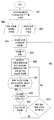
도 3은 이중 속도 센서 흐름도이다. 단계 601은, 시간, PAN, 배터리 모니터링 및 수면 모드를 구성한다. 소프트웨어가, 수신될 데이터의 유형, 데이터의 형식(16 진수) 및 데이터를 전송할 RF 라디오의 식별 번호를 지정하기 위해, 무선 라디오(413)에 대한 구성 설정을 제공할 것이다. 시스템은, 시간, 속도 및 배터리 수명과 관련된 계산에 사용될, 변수들을 정의한다.3 is a dual speed sensor flow chart. Step 601 configures time, PAN, battery monitoring and sleep mode. The software will provide configuration settings for the wireless radio 413 to specify the type of data to be received, the format of the data (in hexadecimal), and the identification number of the RF radio that will transmit the data. The system defines variables to be used in calculations related to time, speed and battery life.
단계 602는, 직렬 포트를 설정하며, 그리고 데이터 입력 핀들을 리셋/구성한다(603). 직렬 포트의 사용을 가능하게 할 명령을 실행하며, 그리고, 직렬 포트로부터 상주 데이터/잘못된 출력을 출력하는 것을 방지하기 위해, 임의의 데이터를 지우도록 직렬 포트를 리셋한다. 아두이노(Arduino) 보드 상의 핀들이, 하나의 하드웨어로부터 다른 하드웨어로 데이터를 전송하기 위해 요구됨에 따라, 입력 또는 출력이 되도록 설정될 것이다. Step 602 sets up a serial port and resets/configures data input pins (603). Execute the command to enable the use of the serial port, and reset the serial port to erase any data to prevent outputting resident data/false output from the serial port. Pins on the Arduino board will be configured to be input or output as required to transfer data from one hardware to another.
단계 604는 속도를 0으로 리셋하도록 설정한다. 이러한 단계는, 구동자 및 종동자 속도 계산을 위한 프로그램에서 계산 오류를 방지하기 위해, 모든 속도 변수들을 0으로 설정한다. 이는, 시스템의 "공제(taring)"또는 "제로화(zeroing)"와 동등한 것이다. Step 604 sets the speed to reset to zero. This step sets all speed variables to zero to avoid calculation errors in the program for calculating driver and follower speeds. This is equivalent to the "taring" or "zeroing" of the system.
단계 605는, PAN을 턴 온하는 것이다. 이는, RF 라디오(413)를 깨우는 것 및 하드웨어 상의 모든 핀들을 턴 온하는 것을 포함한다. Step 605 is to turn on the PAN. This includes waking up the RF radio 413 and turning on all pins on the hardware.
단계 606은, 아날로그 구동자/종동자/배터리 데이터를 샘플링하여 직렬 포트 및 PAN으로 인쇄하는 것이다. 칩(412) 핀들이, 센서들로부터의 전압을 판독함에 의해 데이터를 샘플링한다. Step 606 is to sample the analog driver/follower/battery data and print it to the serial port and PAN.
단계 607은, 판독 가능한 디지털 데이터로의 변환이며, 그리고 데이터를 RF 라디오 PAN 및 직렬 포트로 전송하는 것이다. RPM 계산이, 경과된 시간 및 감지된 구동기 회전수와 관련하여 실행된다. 이는, 구동자 및 종동자 양자 모두에 대해 일어난다. 배터리, 구동자, 및 종동자 데이터는 이어서, RF 라디오(413)를 통해 서버로 전송된다. 이러한 메시지는, 단계 601에서 수행된 구성에 따라 포맷된다.Step 607 is conversion to readable digital data, and transmitting the data to the RF radio PAN and serial port. RPM calculation is performed with respect to the elapsed time and the detected number of drive revolutions. This happens for both driver and follower. The battery, driver, and follower data is then sent to the server via RF radio 413. These messages are formatted according to the configuration performed in
단계 608은 작업이 완료되었는지 질의한다. 일단 RF 라디오 내부 소프트웨어 라이브러리가 데이터를 검증하면, 시스템은, RF 라디오 및 모든 입력/출력 핀들 턴 오프함에 의해 수면 상태로 갈 것이다(609). 데이터가 검증되지 않거나 또는 부정확한 경우, 샘플링 및 변환 프로세스가 반복될 것이다. 사전 결정된 시간 간격이 경과된 경우(610), 시스템을 다시 턴 온하며 그리고 단계 604 내지 단계 609를 수행한다. Step 608 queries if the operation is complete. Once the RF radio internal software library verifies the data, the system will go to sleep (609) by turning off the RF radio and all input/output pins. If the data is not verified or incorrect, the sampling and conversion process will be repeated. If a predetermined time interval has elapsed (610), the system is turned on again and steps 604 to 609 are performed.
도 4는 서버 흐름도이다. 단계 701은, 하드웨어, 직렬 포트, PAN 및 RF 라디오를 구성하는 것을 포함한다. 직렬 포트 사용을 허용하기 위한 그리고 디버깅(debugging) 목적으로 데이터를 출력하도록 직렬 포트를 적절하게 구성하기 위한, 명령이, 실행된다. 또한, RF 라디오(413) 모듈 뿐만 아니라, 데이터를 검증할 그리고 데이터를 판독 가능한 데이터로 변환할, 그의 데이터 분석기의 사용을 가능하게 하기 위한, 명령이, 실행된다. 이러한 분석기는, RF 라디오로부터 이용 가능하다. 4 is a server flow chart. Step 701 includes configuring the hardware, serial port, PAN and RF radio. Instructions are executed to allow the use of the serial port and to properly configure the serial port to output data for debugging purposes. In addition, an RF radio 413 module, as well as instructions to verify data and convert data into readable data, to enable the use of its data analyzer, is executed. Such analyzers are available from RF radios.
단계 702, 단계 703 및 단계 704는, SQLite 데이터베이스 및 테이블들을 생성하고, 클라우드와 함께 IoT 설정을 개시하며, 그리고 직렬 포트 데이터를 개방한다. 새로운 SQLite 데이터베이스를 생성하며 그리고, SQLite와 연결하기 위한 자바 스크립트 전용 명령을 사용하여, 홀 효과 센서들 및 센서 설정을 위한 테이블들을 생성한다. 변수들이, 클라우드 플랫폼과 함께하는 사용을 위해 표시된다. 인텔 기지국 보드(412)와 클라우드 사이에서 샘플 메시지를 보냄(pinging)으로써 센서 시스템과 클라우드 사이의 연결성이, 테스트된다(705). 직렬 포트 통신을 개방하고, 임의의 부정확한 데이터를 회피하거나 오래된 데이터를 제거하기 위해 직렬 포트를 정화하며(706), 그리고 이어서 RF 라디오로부터의 데이터가 적절한 형식인지 검증한다.
단계 707은, 구동자 및 종동자 데이터를 PAN 및 RF 라디오에 인쇄하는 것이다. Step 707 is to print the driver and follower data to the PAN and RF radio.
단계 708은, 데이터베이스 설정을 구성하는 그리고 그러한 설정을 저장하는 것이다. RF 라디오가 기지국 하드웨어로 전송하는 16 진수 메시지를, 판독 가능한 데이터로 분할함에 의해, 날짜, 시간, 시스템의 어떤 부분이 주어진 데이터 패킷을 종료하는지, 어떤 유형의 데이터가 전송되는지, 구동자 속도 및 종동자 속도를 포함하는, 시스템 및 홀 효과 센서들로부터의 데이터를 전송한다. SQLite 데이터베이스는, 데이터를 전송하기 위한 하드웨어를 위한 변수 및 경로를 생성함에 의해, 데이터를 수신하도록 준비한다.Step 708 is to configure database settings and to store those settings. By dividing the hexadecimal message that the RF radio sends to the base station hardware into readable data, the date, time, which part of the system ends the given data packet, what type of data is transmitted, driver speed and slave Data from the system and Hall effect sensors, including pupil velocity. The SQLite database prepares to receive data by creating variables and paths for the hardware to transfer the data.
단계 709는, 효율 및 배터리 데이터를 검색하는 것이다. RF 라디오 메시지 데이터 형식으로부터 나머지 데이터 조각들을 분리하며 그리고 효율 및 배터리 수명 데이터를 계산한다. Step 709 is to retrieve efficiency and battery data. Separate the remaining pieces of data from the RF radio message data format and calculate efficiency and battery life data.
단계 710은 서버 설정이다. 직렬 포트는 SQLite 데이터베이스를 개방할 것이며, 그리고 서버는 데이터를 수신하기 시작할 것이다. Step 710 is server setting. The serial port will open the SQLite database, and the server will start receiving data.
단계 711에서, 서버는 입력을 수신한다. 단계 702 내지 단계 709로부터 수집된 모든 정보는, 단계 702에서 설정된, SQLite 테이블 내에 삽입된다. In
서버는, 이어서, 단계 712에서, 속도, 센서 발신자 주소, 및 배터리 레벨을 포함하는, 디지털 데이터를 수신한다. 적절한 경고 및 경보가, 필요에 따라, 전송된다. 출력 그래프 및 예측 분석 정보가, 사용자 인터페이스로 전송된다. 센서 데이터 및 사용자 설정은, SQLite 데이터베이스로부터 읽고 SQLite 데이터베이스에 기록된다. 이는, 시각적으로 확인되며 그리고 단계 708의 성공적인 실행의 결과이다. 전송되는 모든 경고 또는 경보는, 논리 진술에 기초하여 디스플레이되는 메시지들이다. 예를 들어, 배터리 수명이 특정 값 미만이면, 현재 배터리 수명의 디스플레이를 포함할 경고가, 시스템에 출력될 것이고, 그로 인해 배터리 수명에 관한 경고가 발생되었음을 웹사이트 인터페이스를 통해 사용자에게 경고한다. SQLite 데이터베이스 내부의 테이블들로부터 판독한 데이터를 사용하여, 사용자의 분석을 용이하게 하기 위해 현재 시스템 성능의 시각적 이력 및 추세를 제공하기 위한, 그래프가, 생성될 수 있다.The server then receives, at
비록 본 발명의 하나의 형태가 여기에 설명되었지만, 변형들이, 여기에 설명되는 본 발명의 사상 및 범위로부터 벗어남 없이, 부품들의 구성 및 관계에 관해 이루어질 수 있다는 것이, 당업자에게 명백할 것이다. Although one form of the invention has been described herein, it will be apparent to those skilled in the art that modifications can be made to the construction and relationship of the parts without departing from the spirit and scope of the invention described herein.
Claims (8)
구동자와 종동자로서, 무단 부재에 의해 연결되는 것인, 구동자와 종동자;
상기 구동자에 부착되는, 자기장을 갖는 제1 자성 부재;
상기 종동자에 부착되는, 자기장을 갖는 제2 자성 부재;
상기 제1 자성 부재의 통과에 의해 야기되는 변화하는 자기장을 검출하도록 배치되는 제1 센서;
상기 제2 자성 부재의 통과에 의해 야기되는 변화하는 자기장을 검출하도록 배치되는 제2 센서;
상기 제1 센서로부터의 제1 데이터 신호를 수신기에 무선으로 전송하도록 구성되는 제1 송신기 및 상기 제2 센서로부터의 제2 데이터 신호를 수신기에 무선으로 전송하도록 구성되는 제2 송신기; 그리고
시스템 파라미터가 그에 의해 계산되며 그리고 사용자에게 제공되도록, 상기 제1 데이터 신호 및 상기 제2 데이터 신호를 조작하도록 구성되는 상기 수신기
를 포함하는 것인, 벨트 구동기 모니터링 시스템. As a belt drive monitoring system:
A driver and a follower, which are connected by an endless member, a driver and a follower;
A first magnetic member having a magnetic field attached to the driver;
A second magnetic member having a magnetic field attached to the follower;
A first sensor arranged to detect a changing magnetic field caused by passage of the first magnetic member;
A second sensor arranged to detect a changing magnetic field caused by passage of the second magnetic member;
A first transmitter configured to wirelessly transmit a first data signal from the first sensor to a receiver and a second transmitter configured to wirelessly transmit a second data signal from the second sensor to the receiver; And
The receiver configured to manipulate the first data signal and the second data signal, such that system parameters are calculated and provided to the user
Belt drive monitoring system comprising a.
상기 무단 부재는 벨트인 것인, 벨트 구동기 모니터링 시스템. According to claim 1,
The endless member is a belt, the belt drive monitoring system.
상기 제1 센서 및 상기 제2 센서는 각각, 홀 효과 센서를 포함하는 것인, 벨트 구동기 모니터링 시스템. According to claim 1,
The first sensor and the second sensor, each of which includes a Hall effect sensor, belt drive monitoring system.
상기 제1 자성 부재의 통과에 의해 야기되는 변화하는 자기장을 검출하도록 배치되는 제3 센서; 및
상기 제2 자성 부재의 통과에 의해 야기되는 변화하는 자기장을 검출하도록 배치되는 제4 센서를 더 포함하는 것인, 벨트 구동기 모니터링 시스템. According to claim 1,
A third sensor arranged to detect a changing magnetic field caused by passage of the first magnetic member; And
And a fourth sensor arranged to detect a changing magnetic field caused by passage of the second magnetic member.
상기 제3 센서 및 상기 제4 센서는 각각, 홀 효과 센서를 포함하는 것인, 벨트 구동기 모니터링 시스템.According to claim 4,
The third sensor and the fourth sensor, each of which includes a Hall effect sensor, belt drive monitoring system.
상기 제1 송신기는 상기 제3 센서로부터의 제3 데이터 신호를 수신기에 무선으로 전송하도록 구성되며, 그리고 상기 제2 송신기는 상기 제4 센서로부터의 제4 데이터 신호를 수신기에 무선으로 전송하도록 구성되는 것인, 벨트 구동기 모니터링 시스템. The method of claim 5,
The first transmitter is configured to wirelessly transmit a third data signal from the third sensor to a receiver, and the second transmitter is configured to wirelessly transmit a fourth data signal from the fourth sensor to the receiver. Belt drive monitoring system.
상기 시스템 파라미터는, 속도 차이, 슬립 비율, 또는 구동기 효율 중의 하나를 포함하는 것인, 벨트 구동기 모니터링 시스템. According to claim 1,
Wherein the system parameters include one of speed difference, slip ratio, or driver efficiency.
상기 시스템 파라미터는, 속도 차이, 슬립 비율, 또는 구동기 효율 중의 하나를 포함하는 것인, 벨트 구동기 모니터링 시스템.The method of claim 6,
Wherein the system parameters include one of speed difference, slip ratio, or driver efficiency.
Applications Claiming Priority (3)
| Application Number | Priority Date | Filing Date | Title |
|---|---|---|---|
| US201762583659P | 2017-11-09 | 2017-11-09 | |
| US62/583,659 | 2017-11-09 | ||
| PCT/US2018/059650 WO2019094485A1 (en) | 2017-11-09 | 2018-11-07 | Belt Drive Monitoring System |
Publications (2)
| Publication Number | Publication Date |
|---|---|
| KR20200080298A true KR20200080298A (en) | 2020-07-06 |
| KR102546901B1 KR102546901B1 (en) | 2023-06-22 |
Family
ID=64453633
Family Applications (1)
| Application Number | Title | Priority Date | Filing Date |
|---|---|---|---|
| KR1020207015808A KR102546901B1 (en) | 2017-11-09 | 2018-11-07 | Belt drive monitoring system |
Country Status (9)
| Country | Link |
|---|---|
| US (1) | US10962444B2 (en) |
| EP (1) | EP3707491B1 (en) |
| JP (2) | JP7186776B2 (en) |
| KR (1) | KR102546901B1 (en) |
| CN (1) | CN111465832B (en) |
| AU (1) | AU2018366033B2 (en) |
| CA (1) | CA3081836C (en) |
| MX (1) | MX2020004800A (en) |
| WO (1) | WO2019094485A1 (en) |
Families Citing this family (3)
| Publication number | Priority date | Publication date | Assignee | Title |
|---|---|---|---|---|
| DE102020118189B4 (en) * | 2020-07-09 | 2022-06-09 | Rolf Gnauert | Belt Breakage Monitoring System |
| EP4002318A1 (en) * | 2020-11-16 | 2022-05-25 | ABB Schweiz AG | Method for monitoring a first machine and a second machine, sensor set, and use of a sensor set for monitoring a first machine and a second machine |
| CN116899924B (en) * | 2023-09-07 | 2023-11-17 | 常州创盛智能装备股份有限公司 | Lithium battery cross visual inspection device and lithium battery cross visual inspection test method |
Citations (2)
| Publication number | Priority date | Publication date | Assignee | Title |
|---|---|---|---|---|
| JP3123044U (en) * | 2006-02-22 | 2006-07-06 | ソフトロニクス株式会社 | Conveyor motor device |
| US20110316525A1 (en) * | 2010-06-24 | 2011-12-29 | William David Lynn | Power transmission monitoring and maintenance systems and methods |
Family Cites Families (18)
| Publication number | Priority date | Publication date | Assignee | Title |
|---|---|---|---|---|
| JPS5746522U (en) * | 1980-08-25 | 1982-03-15 | ||
| JPS59140954A (en) * | 1983-01-31 | 1984-08-13 | Hino Motors Ltd | Device for predicting cutoff of cogged belt |
| US5426362A (en) * | 1992-09-30 | 1995-06-20 | Ninnis; Ronald M. | Damage detection apparatus and method for a conveyor belt having magnetically permeable members |
| JP3123044B2 (en) * | 1993-08-11 | 2001-01-09 | 船井電機株式会社 | Disc clamp device |
| US20010045835A1 (en) * | 2000-02-25 | 2001-11-29 | Ahmed Adel Abdel Aziz | Method and apparatus for detecting timing belt damage by inductive coupling |
| US6532810B1 (en) * | 2000-03-17 | 2003-03-18 | Adel Abdel Aziz Ahmed | Method and apparatus for detecting timing belt damage using inductive link coupling |
| GB0107900D0 (en) * | 2001-03-29 | 2001-05-23 | Post Office | Improvements in monitoring systems |
| GB0517759D0 (en) * | 2005-09-01 | 2005-10-12 | Fenner Dunlop Ltd | Conveyor belt monitoring |
| EP2077409A4 (en) * | 2006-10-23 | 2010-09-08 | Jtekt Corp | Control device for stepless transmission, flow rate control method, and flow rate control device |
| AU2008208579B2 (en) * | 2007-01-26 | 2013-05-02 | ContiTech Services (Pty.) Ltd. | Monitoring of conveyor belts |
| US8312987B2 (en) * | 2008-01-16 | 2012-11-20 | The Gates Corporation | Belt monitoring systems and methods |
| AU2009293398A1 (en) | 2008-09-19 | 2010-03-25 | Fenner Dunlop Americas, Inc. | Conveyor belt rip panels and belt rip monitoring |
| US9366547B2 (en) * | 2009-12-07 | 2016-06-14 | Ams Ag | Sensor arrangement and method for operating a sensor arrangement |
| DE102011121842A1 (en) | 2011-12-21 | 2013-06-27 | Robert Bosch Gmbh | Device for measuring torque, direction of rotation and Drehverwidigkeit a shaft of a transmission, in particular an output shaft of an azimuth gear of a wind turbine |
| CN104053616B (en) * | 2012-01-23 | 2016-05-25 | Abb技术有限公司 | Be used for the system and method for the situation of monitoring conveyer belt |
| WO2014159895A1 (en) * | 2013-03-13 | 2014-10-02 | Husqvarna Ab | Slip controlling belt tension system |
| AU2014328480A1 (en) * | 2013-09-24 | 2016-04-14 | Vayeron Pty Ltd | An idler, a method for monitoring a plurality of idlers, and a conveyor system |
| US9260903B1 (en) | 2014-11-07 | 2016-02-16 | Continental Automotive Systems, Inc. | High resolution motor speed for closed-loop speed control |
-
2018
- 2018-11-07 MX MX2020004800A patent/MX2020004800A/en unknown
- 2018-11-07 US US16/183,124 patent/US10962444B2/en active Active
- 2018-11-07 JP JP2020525932A patent/JP7186776B2/en active Active
- 2018-11-07 CN CN201880080577.4A patent/CN111465832B/en active Active
- 2018-11-07 EP EP18807821.6A patent/EP3707491B1/en active Active
- 2018-11-07 CA CA3081836A patent/CA3081836C/en active Active
- 2018-11-07 WO PCT/US2018/059650 patent/WO2019094485A1/en unknown
- 2018-11-07 KR KR1020207015808A patent/KR102546901B1/en active IP Right Grant
- 2018-11-07 AU AU2018366033A patent/AU2018366033B2/en active Active
-
2022
- 2022-07-15 JP JP2022114027A patent/JP2022137251A/en active Pending
Patent Citations (2)
| Publication number | Priority date | Publication date | Assignee | Title |
|---|---|---|---|---|
| JP3123044U (en) * | 2006-02-22 | 2006-07-06 | ソフトロニクス株式会社 | Conveyor motor device |
| US20110316525A1 (en) * | 2010-06-24 | 2011-12-29 | William David Lynn | Power transmission monitoring and maintenance systems and methods |
Also Published As
| Publication number | Publication date |
|---|---|
| EP3707491B1 (en) | 2022-03-09 |
| US20190137358A1 (en) | 2019-05-09 |
| BR112020009060A2 (en) | 2020-10-06 |
| AU2018366033B2 (en) | 2021-09-16 |
| CN111465832B (en) | 2022-08-26 |
| KR102546901B1 (en) | 2023-06-22 |
| MX2020004800A (en) | 2020-10-22 |
| CA3081836A1 (en) | 2019-05-16 |
| WO2019094485A1 (en) | 2019-05-16 |
| JP7186776B2 (en) | 2022-12-09 |
| EP3707491A1 (en) | 2020-09-16 |
| AU2018366033A1 (en) | 2020-05-21 |
| JP2021502315A (en) | 2021-01-28 |
| CA3081836C (en) | 2022-11-22 |
| US10962444B2 (en) | 2021-03-30 |
| JP2022137251A (en) | 2022-09-21 |
| CN111465832A (en) | 2020-07-28 |
Similar Documents
| Publication | Publication Date | Title |
|---|---|---|
| CN109792227B (en) | System for monitoring conditions of multiple motors | |
| JP2022137251A (en) | Belt drive monitoring system | |
| US9726576B2 (en) | Equipment monitoring system | |
| US20170108407A1 (en) | Machine component diagnosis system and server thereof | |
| US10697822B2 (en) | Devices, methods and computer program products providing multi-axis vibrational measurement with predictive analysis | |
| CN104516302A (en) | Tool and method for monitoring state of tool | |
| CN105209995A (en) | Monitoring system and diagnostic device and monitoring terminal thereof | |
| CN110100158A (en) | The condition monitoring system of whirler, the state monitoring method of whirler, program and storage medium | |
| US11225334B2 (en) | Systems and methods for monitoring the health of a rotating machine | |
| CN117234783A (en) | PCIE equipment detection method and device, BIOS and storage medium | |
| US20160003668A1 (en) | Monitoring device | |
| JP2017151802A (en) | Inspection system for alarm device using portable terminal, and inspection method using the same | |
| WO2018176203A1 (en) | Method and device for use in estimating lifecycle of component | |
| CN211086969U (en) | Instrument calibration device and system | |
| CN105264584A (en) | One touch data collection method and medium | |
| CN105229630B (en) | One-touch transacter | |
| BR112020009060B1 (en) | BELT DRIVE MONITORING SYSTEM | |
| CN108151795B (en) | Method and system for configuring a condition monitoring device | |
| WO2017051832A1 (en) | Component state detection device | |
| CN116974849A (en) | Method, device, equipment and medium for monitoring temperature of air inlet of server | |
| CN205483332U (en) | Novel detection and control system appearance is patrolled to intelligence temperature | |
| CN113632546A (en) | Condition monitoring system and method | |
| CN104728143A (en) | Fan detector | |
| KR20080082073A (en) | Navigational Equipment Condition Inspection Method |
Legal Events
| Date | Code | Title | Description |
|---|---|---|---|
| PA0105 | International application |
Patent event date: 20200602 Patent event code: PA01051R01D Comment text: International Patent Application |
|
| PA0201 | Request for examination | ||
| PG1501 | Laying open of application | ||
| E902 | Notification of reason for refusal | ||
| PE0902 | Notice of grounds for rejection |
Comment text: Notification of reason for refusal Patent event date: 20210727 Patent event code: PE09021S01D |
|
| AMND | Amendment | ||
| E601 | Decision to refuse application | ||
| PE0601 | Decision on rejection of patent |
Patent event date: 20211230 Comment text: Decision to Refuse Application Patent event code: PE06012S01D Patent event date: 20210727 Comment text: Notification of reason for refusal Patent event code: PE06011S01I |
|
| AMND | Amendment | ||
| PX0901 | Re-examination |
Patent event code: PX09011S01I Patent event date: 20211230 Comment text: Decision to Refuse Application Patent event code: PX09012R01I Patent event date: 20210927 Comment text: Amendment to Specification, etc. |
|
| PX0601 | Decision of rejection after re-examination |
Comment text: Decision to Refuse Application Patent event code: PX06014S01D Patent event date: 20220308 Comment text: Amendment to Specification, etc. Patent event code: PX06012R01I Patent event date: 20220223 Comment text: Decision to Refuse Application Patent event code: PX06011S01I Patent event date: 20211230 Comment text: Amendment to Specification, etc. Patent event code: PX06012R01I Patent event date: 20210927 Comment text: Notification of reason for refusal Patent event code: PX06013S01I Patent event date: 20210727 |
|
| X601 | Decision of rejection after re-examination | ||
| J201 | Request for trial against refusal decision | ||
| PJ0201 | Trial against decision of rejection |
Patent event date: 20220408 Comment text: Request for Trial against Decision on Refusal Patent event code: PJ02012R01D Patent event date: 20220308 Comment text: Decision to Refuse Application Patent event code: PJ02011S01I Patent event date: 20211230 Comment text: Decision to Refuse Application Patent event code: PJ02011S01I Appeal kind category: Appeal against decision to decline refusal Appeal identifier: 2022101000797 Request date: 20220408 |
|
| J301 | Trial decision |
Free format text: TRIAL NUMBER: 2022101000797; TRIAL DECISION FOR APPEAL AGAINST DECISION TO DECLINE REFUSAL REQUESTED 20220408 Effective date: 20230307 |
|
| PJ1301 | Trial decision |
Patent event code: PJ13011S01D Patent event date: 20230307 Comment text: Trial Decision on Objection to Decision on Refusal Appeal kind category: Appeal against decision to decline refusal Request date: 20220408 Decision date: 20230307 Appeal identifier: 2022101000797 |
|
| PS0901 | Examination by remand of revocation | ||
| GRNO | Decision to grant (after opposition) | ||
| PS0701 | Decision of registration after remand of revocation |
Patent event date: 20230317 Patent event code: PS07012S01D Comment text: Decision to Grant Registration Patent event date: 20230310 Patent event code: PS07011S01I Comment text: Notice of Trial Decision (Remand of Revocation) |
|
| GRNT | Written decision to grant | ||
| PR0701 | Registration of establishment |
Comment text: Registration of Establishment Patent event date: 20230620 Patent event code: PR07011E01D |
|
| PR1002 | Payment of registration fee |
Payment date: 20230620 End annual number: 3 Start annual number: 1 |
|
| PG1601 | Publication of registration |