KR20200077237A - Agitator wing and dispenser comprising the same - Google Patents
Agitator wing and dispenser comprising the same Download PDFInfo
- Publication number
- KR20200077237A KR20200077237A KR1020180166558A KR20180166558A KR20200077237A KR 20200077237 A KR20200077237 A KR 20200077237A KR 1020180166558 A KR1020180166558 A KR 1020180166558A KR 20180166558 A KR20180166558 A KR 20180166558A KR 20200077237 A KR20200077237 A KR 20200077237A
- Authority
- KR
- South Korea
- Prior art keywords
- wing
- disposed
- container
- stirring blade
- driving
- Prior art date
Links
Images


Classifications
-
- B—PERFORMING OPERATIONS; TRANSPORTING
- B67—OPENING, CLOSING OR CLEANING BOTTLES, JARS OR SIMILAR CONTAINERS; LIQUID HANDLING
- B67D—DISPENSING, DELIVERING OR TRANSFERRING LIQUIDS, NOT OTHERWISE PROVIDED FOR
- B67D1/00—Apparatus or devices for dispensing beverages on draught
- B67D1/08—Details
- B67D1/0878—Safety, warning or controlling devices
- B67D1/0882—Devices for controlling the dispensing conditions
- B67D1/0884—Means for controlling the parameters of the state of the liquid to be dispensed, e.g. temperature, pressure
-
- B01F15/00538—
-
- B01F15/00668—
-
- B—PERFORMING OPERATIONS; TRANSPORTING
- B01—PHYSICAL OR CHEMICAL PROCESSES OR APPARATUS IN GENERAL
- B01F—MIXING, e.g. DISSOLVING, EMULSIFYING OR DISPERSING
- B01F27/00—Mixers with rotary stirring devices in fixed receptacles; Kneaders
- B01F27/05—Stirrers
- B01F27/11—Stirrers characterised by the configuration of the stirrers
- B01F27/113—Propeller-shaped stirrers for producing an axial flow, e.g. shaped like a ship or aircraft propeller
-
- B—PERFORMING OPERATIONS; TRANSPORTING
- B01—PHYSICAL OR CHEMICAL PROCESSES OR APPARATUS IN GENERAL
- B01F—MIXING, e.g. DISSOLVING, EMULSIFYING OR DISPERSING
- B01F35/00—Accessories for mixers; Auxiliary operations or auxiliary devices; Parts or details of general application
- B01F35/30—Driving arrangements; Transmissions; Couplings; Brakes
- B01F35/32—Driving arrangements
- B01F35/32005—Type of drive
- B01F35/3204—Motor driven, i.e. by means of an electric or IC motor
-
- B—PERFORMING OPERATIONS; TRANSPORTING
- B01—PHYSICAL OR CHEMICAL PROCESSES OR APPARATUS IN GENERAL
- B01F—MIXING, e.g. DISSOLVING, EMULSIFYING OR DISPERSING
- B01F35/00—Accessories for mixers; Auxiliary operations or auxiliary devices; Parts or details of general application
- B01F35/40—Mounting or supporting mixing devices or receptacles; Clamping or holding arrangements therefor
- B01F35/41—Mounting or supporting stirrer shafts or stirrer units on receptacles
-
- B01F7/00341—
-
- B01F2015/00084—
-
- B—PERFORMING OPERATIONS; TRANSPORTING
- B01—PHYSICAL OR CHEMICAL PROCESSES OR APPARATUS IN GENERAL
- B01F—MIXING, e.g. DISSOLVING, EMULSIFYING OR DISPERSING
- B01F35/00—Accessories for mixers; Auxiliary operations or auxiliary devices; Parts or details of general application
- B01F35/30—Driving arrangements; Transmissions; Couplings; Brakes
- B01F2035/35—Use of other general mechanical engineering elements in mixing devices
- B01F2035/351—Sealings
-
- B—PERFORMING OPERATIONS; TRANSPORTING
- B67—OPENING, CLOSING OR CLEANING BOTTLES, JARS OR SIMILAR CONTAINERS; LIQUID HANDLING
- B67D—DISPENSING, DELIVERING OR TRANSFERRING LIQUIDS, NOT OTHERWISE PROVIDED FOR
- B67D2210/00—Indexing scheme relating to aspects and details of apparatus or devices for dispensing beverages on draught or for controlling flow of liquids under gravity from storage containers for dispensing purposes
- B67D2210/0016—Adapted for dispensing high viscosity products
- B67D2210/00163—Agitators
Landscapes
- Chemical & Material Sciences (AREA)
- Chemical Kinetics & Catalysis (AREA)
- Engineering & Computer Science (AREA)
- Aviation & Aerospace Engineering (AREA)
- Food-Manufacturing Devices (AREA)
Abstract
Description
본 발명은 교반용 날개 및 이를 포함하는 디스펜서에 관한 것이다.The present invention relates to a stirring blade and a dispenser comprising the same.
음료수, 국 따위의 내용물을 제공하는 디스펜서는 바디, 바디에 놓이고 내용물이 저장되는 용기, 저장된 내용물을 혼합하는 교반부를 포함한다. 그리고 용기에는 음료의 배출콕이 설치되어 있다.The dispenser providing contents such as drinks and soups includes a body, a container placed on the body and the contents stored therein, and a stirring unit mixing the stored contents. In addition, a container for discharging beverages is provided.
교반부는, 용기 내부에 위치한 날개 및 용기 외부에 배치되어 날개와 연결되어 날개를 회전시키는 구동부를 포함한다. 용기는 바디에 고정되어 있고 구동부는 바디에 배치된 상태에서 용기를 관통하여 날개와 연결되어 있다. 이에 용기와 바디를 분리할 수 없어 용기 내부 세척이 불편하였다.The stirring unit includes a wing positioned inside the container and a driving unit disposed outside the container to connect the wing to rotate the wing. The container is fixed to the body, and the driving part penetrates the container and is connected to the wing in a state arranged on the body. Accordingly, it was inconvenient to wash the inside of the container because the container and the body could not be separated.
이에, 바디 위에 용기를 단순히 올려 놓고 구동부와 날개를 자기력으로 연결하여 날개를 회전시키는 기술이 제안되고 있다. 그러나 용기가 바디에 고정되지 않아 날개 회전 시 용기가 흔들리게 되었다. 또한, 날개가 ABS(acrylonitrile butadiene styrene copolymer)수지 따위로 만들어지면서 용기에 저장된 내용물의 높은 열로 인해 ABS 수지가 손상되면서 위생적이지 못하였다.Accordingly, a technique has been proposed in which a container is simply placed on a body, and the wing is rotated by connecting the driving unit and the wing with a magnetic force. However, since the container is not fixed to the body, the container is shaken when the blade is rotated. In addition, as the wings were made of ABS (acrylonitrile butadiene styrene copolymer) or the like, it was not hygienic as the ABS resin was damaged due to the high heat of the contents stored in the container.
본 발명은 교반용 날개가 용기에 수용된 내용물의 열에 영향을 받지 않으며, 교반용 날개가 회전할 때 용기가 흔들리지 않도록 하는 기술을 제공한다.The present invention provides a technique in which the stirring blade is not affected by the heat of the contents contained in the container, and the container does not shake when the stirring blade rotates.
본 발명의 한 실시예에 따른 교반용 날개는, 샤프트 홀이 상하 관통되어 있고 내부 공간을 갖는 날개 하우징, 상기 내부 공간에 배치된 적어도 하나의 자성체, 상기 샤프트 홀 주변에 배치되어 상기 날개 하우징의 상측부재와 하측부재를 연결하는 지지부 및 접촉면에 놓일 수 있으며 상기 날개 하우징이 회전할 수 있도록 지지하는 날개 샤프트를 포함한다.A stirring blade according to an embodiment of the present invention, the shaft hole is penetrated up and down, the wing housing having an inner space, at least one magnetic body disposed in the inner space, the shaft hole is disposed around the upper side of the wing housing It includes a support shaft connecting the member and the lower member and a wing shaft which can be placed on a contact surface and supports the wing housing to rotate.
상기 날개 하우징은 구동부와 상기 자성체의 인력에 의해 상기 날개 샤프트를 기준으로 회전할 수 있다.The wing housing may rotate relative to the wing shaft by the attraction of the driving unit and the magnetic body.
상기 상측부재와 하측부재는 간격을 두고 마주하되 가장자리는 서로 연결되어 있고 상기 샤프트 홀은 중앙을 상하 관통할 수 있다.The upper member and the lower member face each other at intervals, but the edges are connected to each other, and the shaft hole may penetrate the center vertically.
상기 지지부는, 상기 상측부재와 하측부재 사이에 위치하여 상기 샤프트 홀 주변을 지지하는 내측 지지부를 포함할 수 있다.The support part may include an inner support part positioned between the upper member and the lower member to support the shaft hole.
상기 지지부는, 상기 샤프트 홀에 위치하고 상기 상측부재와 하측부재의 외측을 내측 방향으로 가압하는 외측 지지부를 더 포함할 수 있다.The support portion may further include an outer support portion positioned in the shaft hole and pressing the outer side of the upper and lower members in an inner direction.
상기 외측 지지부는, 상기 날개 하우징의 상측부재와 하측부재의 외측에 각각 배치된 오링, 상기 샤프트 홀을 관통하고 상부와 하부가 상기 오링을 상기 상측부재와 하측부재로 가압하는 고정부재 및 상기 고정부재를 관통하고 상기 고정부재와 상기 상측부재와 하측부재를 덮고 있으며 상기 슬리브가 관통하고 있는 어댑터를 포함할 수 있다.The outer support portion, O-rings respectively disposed on the outer side of the upper and lower members of the wing housing, the fixing member and the fixing member that penetrates the shaft hole and presses the O-ring to the upper member and the lower member. It may include an adapter that penetrates through and covers the fixing member, the upper member, and the lower member, and through which the sleeve penetrates.
상기 교반용 날개는 지지부와 결합되어 있고 상기 날개 샤프트가 관통하는 슬리브를 더 포함할 수 있다.The stirring blade may further include a sleeve that is coupled to the support portion and through which the blade shaft passes.
상기 날개 샤프트는, 상기 접촉면에 놓이는 플랜지 및 상기 플랜지 중앙에서 돌출되어 상기 슬리브를 관통하는 로드를 포함할 수 있다.The wing shaft may include a flange placed on the contact surface and a rod protruding from the center of the flange and penetrating the sleeve.
상기 슬리브와 상기 로드 사이에 틈새가 형성될 수 있다.A gap may be formed between the sleeve and the rod.
상기 교반용 날개는 상기 슬리브와 상기 플랜지 사이에 배치된 와셔부를 더 포함할 수 있다.The stirring blade may further include a washer portion disposed between the sleeve and the flange.
상기 슬리브와 상기 와셔부는 점 접촉할 수 있다.The sleeve and the washer portion may be in point contact.
상기 상측부재와 하측부재에는 각각 보강부가 형성되어 있고, 상기 보강부는 상기 상측부재와 하측부재의 내부면에 외측방향으로 가압될 수 잇다.Reinforcing portions are formed on the upper and lower members, respectively, and the reinforcing portions can be pressed outwardly on the inner surfaces of the upper and lower members.
상기 교반용 날개는, 상기 상측부재의 상면에 간격을 두고 배치된 적어도 하나의 날개를 더 포함할 수 있다.The stirring blade may further include at least one blade disposed at intervals on the upper surface of the upper member.
본 발명의 한 실시예에 따른 교반용 날개는, 상기와 같은 교반용 날개, 보관공간과 구동공간을 갖는 본체부, 개방된 상기 보관공간이 형성된 상기 본체부에 배치된 도어부, 상기 보관공간에 놓여 있으며, 상기 교반용 날개가 내부에 위치한 용기, 상기 본체부에 배치되어 있고 상기 용기에 수용된 내용물의 온도를 조절하는 온도 조절부 및 상기 구동공간에 배치되어 있고 자기력으로 상기 교반용 날개와 연결되어 상기 교반용 날개를 회전시키는 구동부를 포함할 수 있다.The stirring blade according to an embodiment of the present invention, the stirring blade as described above, the main body having a storage space and a driving space, the door portion disposed on the main body portion where the open storage space is formed, the storage space Placed, the stirring blade is disposed therein, is disposed in the main body portion and is disposed in the temperature control unit for controlling the temperature of the contents contained in the container and the driving space and is connected to the stirring blade by magnetic force It may include a driving unit for rotating the stirring blade.
상기 용기의 하면과 상기 보관공간의 바닥은 접하며, 상기 하면과 상기 바닥 사이에는 서로 결합된 복수의 요철부 형성될 수 있다.The bottom surface of the container and the bottom of the storage space are in contact, and a plurality of uneven parts coupled to each other may be formed between the bottom surface and the bottom.
상기 구동부는, 상기 구동공간에 배치되어 있는 케이스, 상기 케이스 내부에 회전할 수 있게 배치되어 있고 회전 중심이 교반용 날개의 회전 중심과 일치하는 구동 회전체, 상기 구동 회전체 내부에 배치되어 있는 적어도 하나의 자석 및 상기 구동 회전체를 회전 시키는 구동모터를 포함할 수 있다.The driving unit, a case disposed in the driving space, a driving rotational body arranged to be rotatable inside the case and having a rotational center coinciding with a rotational center of a stirring blade, at least disposed inside the driving rotational body It may include a magnet and a driving motor for rotating the driving rotor.
상기 구동모터와 결합된 풀리 외부둘레는 상기 구동 회전체의 외부둘레와 직접 접할 수 있다.The outer circumference of the pulley coupled with the driving motor may directly contact the outer circumference of the driving rotor.
상기 디스펜서는 상기 용기의 외부 둘레는 상기 본체부 내부 둘레와 이격되어 있으며, 상기 본체부에 배치되어 상기 온도 조절부의 주변 공기를 상기 보관공간으로 유동시키는 휀을 더 포함할 수 있다.The dispenser may further include a fan circumferentially spaced apart from the inner circumference of the main body, and disposed in the main body to flow the ambient air of the temperature control unit to the storage space.
본 발명의 실시예에 따르면, 날개 하우징이 스테인리스 스틸로 형성되어 내용물의 높은 열에 영향을 받지 않아 교반용 날개는 손상되지 않는다. 이에 교반용 날개의 내구성이 향상되며 열에 의해 교반용 날개가 손상되면서 발생한 위생적인 문제를 예방할 수 있다.According to an embodiment of the present invention, the wing housing is formed of stainless steel and is not affected by high heat of the contents, so that the wing for stirring is not damaged. Accordingly, the durability of the stirring blade is improved, and hygienic problems caused by damage to the stirring blade due to heat can be prevented.
본 발명의 실시예에 따르면, 날개 샤프트의 로드와 슬리브 사이에 틈새가 발생하여 날개가 결합된 날개 하우징은 날개 샤프트를 기준으로 회전할 수 있다. 슬리브 사용으로 베어링을 사용을 배제함으로써 위생적인 디스펜서를 제공할 수 있다.According to an embodiment of the present invention, a gap is generated between the rod and the sleeve of the wing shaft so that the wing housing to which the wings are coupled can rotate relative to the wing shaft. The use of sleeves eliminates the use of bearings to provide a sanitary dispenser.
본 발명의 실시예에 따르면, 상측부재와 하측부재의 내부 중앙을 내측 지지부가 지지하고 있고 샤프트 홀에서 외측 지지부가 상측부재와 하측부재를 내측 지지부 방향으로 가압하므로 상측부재와 하측부재의 중앙 부분이 안정적으로 고정될 수 있다.According to an embodiment of the present invention, since the inner support portion supports the inner center of the upper member and the lower member, and the outer support portion presses the upper member and the lower member toward the inner support in the shaft hole, the central portion of the upper member and the lower member is It can be stably fixed.
본 발명의 실시예에 따르면, 상측부재와 하측부재의 샤프트 홀 주변부분에 내측 지지부와 외측 지지부가 배치되어 있어 기밀성이 향상되어 내부공간으로 내용물이 유입되지 않는다.According to an embodiment of the present invention, since the inner support portion and the outer support portion are disposed at the periphery of the shaft hole of the upper member and the lower member, the airtightness is improved and the contents are not introduced into the inner space.
본 발명의 실시예에 따르면, 슬리브와 날개 샤프트 및 와셔부가 세라믹으로 형성되어 날개 하우징 회전 시 서로 접촉부위에서 파티클이 발생하지 않는다. 이에 디스펜서의 위생성이 향상된다.According to an embodiment of the present invention, the sleeve, the wing shaft, and the washer portion are formed of ceramic so that particles are not generated at the contact portions with each other when the wing housing is rotated. This improves the hygiene of the dispenser.
본 발명의 실시예에 따르면 용기 요철부와 본체 요철부가 서로 맞물리어 용기와 본체부가 서로 결합되므로 용기 내부에서 교반용 날개가 회전하여 내용물이 유동하여도 용기는 흔들리지 않는다. 이에 용기의 안정성이 높다.According to an embodiment of the present invention, since the container irregularities and the body irregularities are engaged with each other, the container and the main body are coupled to each other, so that the container is not shaken even when the stirring blade rotates inside the container and the contents flow. Thus, the stability of the container is high.
본 발명의 실시예에 따르면 구동부의 풀리와 구동 회전체가 서로 접한 상태에서 풀리의 회전력이 구동 회전체에 전달되므로 벨트 따위의 동력전달수단 사용을 배제할 수 있다. 이에 구동 회전체와 풀리가 위치하는 케이스를 슬립화할 수 있다. 이로 인하여 디스펜서 전체를 슬립하게 형성할 수 있다.According to the exemplary embodiment of the present invention, since the rotational force of the pulley is transmitted to the driving rotating body in a state where the driving unit pulley and the driving rotating body are in contact with each other, the use of a power transmission means such as a belt can be excluded. Accordingly, the case in which the driving rotator and the pulley are located can slip. Due to this, the entire dispenser can be slipped.
본 발명의 실시예에 따르면, 용기의 외부 둘레가 본체부의 내부 둘레와 이격되어 있고 휀의 구동으로 온도 조절부 주변 공기가 통기홀을 통해 보관공간으로 유입될 수 있다. 이때 온도 조절부의 주변 공기가 보관공간을 통해 용기에 전달되므로 간접적으로 용기에 수용된 내용물에 전달될 수 있다. 이에 온도 조절부 주변 공기가 용기에 직접 전달되지 않으므로 발효물에 전달되는 온도가 내용물의 발효 온도를 적정온도에서 크게 변화하지 않는다. 내용물의 최적 발효 온도를 유지할 수 있어 내용물의 발효 효율이 높아진다.According to an embodiment of the present invention, the outer circumference of the container is spaced apart from the inner circumference of the main body, and the air around the temperature control unit may be introduced into the storage space through the ventilation hole by driving the fan. At this time, since the ambient air of the temperature control unit is delivered to the container through the storage space, it may be indirectly delivered to the contents contained in the container. Accordingly, since the air around the temperature control unit is not directly delivered to the container, the temperature delivered to the fermentation product does not significantly change the fermentation temperature of the contents at an appropriate temperature. It is possible to maintain the optimum fermentation temperature of the contents, which increases the fermentation efficiency of the contents.
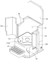
도 1은 본 발명의 한 실시예에 따른 디스펜서를 나타낸 사시도.
도 2는 도 1의 보관공간에 용기가 위치한 상태를 나타낸 개략도.
도 3은 도 2의 도어부가 닫힌 상태를 나타낸 개략도.
도 4는 도 2의 본체부와 용기부의 일부분을 나타낸 단면도.
도 5는 도 4의 교반용 날개와 구동부의 연결 상태를 나타낸 개략도.
도 6은 도 4의 교반용 날개를 나타낸 사시도.
도 7은 도 6의 분해 사시도.
도 8은 도 6을 Ⅷ-Ⅷ 선을 따라 자른 단면도.
도 9는 도 8의 내측 지지부와 외측 지지부 확대도.
도 10은 본 발명의 다른 실시예에 따른 디스펜서를 나타낸 사시도.1 is a perspective view showing a dispenser according to an embodiment of the present invention.
Figure 2 is a schematic diagram showing a state in which the container is located in the storage space of Figure 1;
3 is a schematic view showing a state in which the door portion of FIG. 2 is closed;
Figure 4 is a cross-sectional view showing a portion of the body portion and the container portion of FIG.
Figure 5 is a schematic diagram showing the connection state of the stirring blade and the driving unit of Figure 4;
Figure 6 is a perspective view showing the stirring blade of Figure 4;
7 is an exploded perspective view of FIG. 6.
8 is a cross-sectional view of FIG. 6 taken along the line VII-VII.
9 is an enlarged view of the inner and outer supports of FIG. 8.
10 is a perspective view showing a dispenser according to another embodiment of the present invention.
이하, 본 발명이 속하는 기술 분야에서 통상의 지식을 가진 자가 용이하게 실시할 수 있도록 본 발명의 실시예에 대하여 첨부한 도면을 참고로 하여 상세히 설명한다. 그러나 본 발명은 여러 가지 상이한 형태로 구현될 수 있으며 여기에서 설명하는 실시예에 한정되지 않는다. 명세서 전체를 통하여 유사한 부분에 대해서는 동일한 도면 부호를 붙였다.Hereinafter, embodiments of the present invention will be described in detail with reference to the accompanying drawings so that those skilled in the art to which the present invention pertains may easily practice. However, the present invention can be implemented in many different forms and is not limited to the embodiments described herein. The same reference numerals are used for similar parts throughout the specification.
본 발명의 실시예에 따른 교반용 날개는 본 발명의 디스펜서에 적용될 수 있는 바, 이하에서는 교반용 날개가 적용된 디스펜서 위주로 설명한다.A stirring blade according to an embodiment of the present invention can be applied to the dispenser of the present invention, hereinafter, mainly described with a dispenser to which the stirring blade is applied.
그러면 본 발명의 한 실시예에 따른 디스펜서에 대하여 도 1 내지 도 9를 참고하여 설명한다.Then, a dispenser according to an embodiment of the present invention will be described with reference to FIGS. 1 to 9.
도 1은 본 발명의 한 실시예에 따른 디스펜서를 나타낸 사시도이고, 도 2는 도 1의 보관공간에 용기가 위치한 상태를 나타낸 개략도이며, 도 3은 도 2의 도어부가 닫힌 상태를 나타낸 개략도이고, 도 4는 도 2의 본체부와 용기부의 일부분을 나타낸 단면도이며, 도 5는 도 4의 교반용 날개와 구동부의 연결 상태를 나타낸 개략도이고, 도 6은 도 4의 교반용 날개를 나타낸 사시도이며, 도 7은 도 6의 분해 사시도이고, 도 8은 도 6을 Ⅷ-Ⅷ 선을 따라 자른 단면도이며, 도 9는 도 8의 내측 지지부와 외측 지지부 확대도이다.1 is a perspective view showing a dispenser according to an embodiment of the present invention, Figure 2 is a schematic diagram showing a state in which the container is located in the storage space of Figure 1, Figure 3 is a schematic view showing the closed state of the door portion of Figure 2, 4 is a cross-sectional view showing a part of the main body and the container of FIG. 2, FIG. 5 is a schematic view showing the connection state of the stirring blade and the driving unit of FIG. 4, and FIG. 6 is a perspective view showing the stirring blade of FIG. 4, FIG. 7 is an exploded perspective view of FIG. 6, FIG. 8 is a cross-sectional view of FIG. 6 taken along the line VII-VII, and FIG. 9 is an enlarged view of the inner and outer supports of FIG. 8.
먼저, 도 1 내지 도 4를 참고하면, 본 실시예에 따른 디스펜서(1)는 본체부(10), 용기(20), 도어부(30), 온도 조절부(40), 교반용 날개(50) 및 구동부(70)를 포함하며, 교반용 날개(50)가 용기(20)에 수용되는 내용물의 열에 영향을 받지 않으며, 교반용 날개(50)가 회전할 때 용기(20)가 흔들리지 않게 안정적으로 놓인 상태를 유지하도록 한다. 여기서, 내용물은 국물, 음료 따위의 유체일 수 있다.First, referring to FIGS. 1 to 4, the
본체부(10)는 디스펜서(1)의 외형을 형성하며 내부가 보관공간(11)과 구동공간(12)으로 구획되어 있다. 보관공간(11)을 이루는 본체부(10)의 상부측은 전면과 상면이 개방되어 있다. 보관공간(11)을 이루고 있는 본체부(10)에는 단열부(도시하지 않음)가 배치되어 있다. 여기서 단열부는 본체부(10)의 내부면과 외부면 사이에 위치한다.The
도면에는 도시하지 않았지만 본체부(10)의 하부에는 하부도어가 배치되어 있다. 하부도어에 의해 구동공간(12)은 개방될 수 있다. 본체부(10)의 하부에는 디스펜서(1)을 운반할 수 있는 손잡이(도시하지 않음)가 형성되어 있다. 또한 본체부(10)의 저면에는 미끄럼방지패드(도시하지 않음) 또는 캐스터(도시하지 않음) 따위가 배치될 수 있다.Although not shown in the drawings, a lower door is disposed under the
보관공간(11)의 바닥(111)에는 본체 요철부(111a)가 형성되어 있다. 그리고 보관공간(11)의 바닥에는 배수홀(도시하지 않음)이 형성되어 있다.The
본체부(10)의 하부 전면에는 컵 따위를 놓을 수 있는 받침대(13)가 배치되어 있다.On the lower front of the
용기(20)는 보관공간(11)에 위치하며 하면이 보관공간(11)의 바닥(111)와 대응되게 형성되어 있다. 이에 용기(20)의 저면에는 본체 요철부(111a)와 대응하는 용기 요철부(22)가 형성되어 있다. 본체 요철부(111a)와 용기 요철부(22)가 서로 맞물려 용기(20)는 보관공간(11) 바닥에 고정되어 움직이지 않는다. 여기서, 본체 요철부(111a)와 용기 요철부(22)의 요철 정도는 2 내지 3mm 일 수 있다. 이러한 본체 요철부(111a)와 용기 요철부(22)는 서로 맞물려 결합력을 높이며 작업자가 용기(20)를 보관공간(11)에서 본체부(10) 외부로 들어내기 용이하다.The
용기(20) 하부에는 배출콕(21)이 형성되어 있다. 배출콕(21)은 본체부(10)의 개방된 전면을 통해 본체부(10) 외부로 노출되어 받침대(13) 위에 위치한다. 용기(20) 내부에는 배출콕(21)을 통해 배출될 수 있는 내용물 따위가 수용될 수 있다.A
용기(20)에서 보관공간(11)의 바닥(111)으로 떨어진 내용물은 배수홀을 통해 본체부(10) 외부로 배수될 수 있다.The contents dropped from the
도어부(30)는 본체부(10)의 개방된 전면과 상면에 각각 배치되어 있다. 도어부(30)는 본체부(10)와 힌지(33) 연결되어 있다. 도어부(30)는 본체부(10)의 전면에 배치된 전면도어(31) 상면에 배치된 상면도어(32)를 포함한다. 전면도어(31)와 상면도어(32)에는 각각 단열부(도시하지 않음)가 배치되어 있다.The
전면도어(31)는 제1 도어(311)와 제2 도어(312)로 분리되어 있다. 제1 도어(311)와 제2 도어(312)는 힌지(33)를 기준으로 움직여 본체부(10)의 개방된 전면을 단속한다.The
제1 도어(311)와 제2 도어(312)가 닫힐 때 배출콕(21)이 전면도어(31) 외부로 노출되도록 제1 도어(311)와 제2 도어(312)가 접하는 부분에는 노출홀(31a)이 형성되어 있다.When the
아울러, 제1 도어(311)와 제2 도어(312)가 접하는 부분 도는 제1 도어(311), 제2 도어(312)가 본체부(10)와 접하는 부분에는 락킹부재(도시하지 않음)가 배치되어 있다. 락킹부재는 제1 도어(311)와 제2 도어(312)의 닫힌 상태를 유지한다.In addition, a locking member (not shown) is provided at a portion where the
온도 조절부(40)는, 보관공간(11)의 바닥 내부에 배치되어 있다. 온도 조절부(40)는 가열수단 또는 냉각수단을 포함한다. 가열수단은 러버히터, 열선, 면상발열체, 열전 소자 따위를 포함할 수 있다. 그리고 냉각수단은 냉동사이클, 열전소자 따위를 포함할 수 있다.The
용기(20)에 수용되는 내용물은 온도 조절부(40)에 의해 가열되거나 냉각될 수 있다. 온도 조절부(40)의 열은 단열부에 의해 본체부(10) 외부로 전달되는 것이 예방될 수 있다.The contents accommodated in the
다음으로 도 5 내지 도 9를 더 참고하여 교반용 날개에 대해 설명한다.Next, a stirring blade will be described with reference to FIGS. 5 to 9 further.
도 5 내지 도 9를 더 참고하면, 교반용 날개(50)는 날개 하우징(51), 자성체(53), 지지부(54) 및 날개 샤프트(56)를 포함하며 용기(20) 내부에 위치하며 내용물이 고르게 섞이도록 내용물을 젓는다.5 to 9, the stirring
날개 하우징(51)은 상측부재(511)와 하측부재(512)를 포함한다. 상측부재(511)와 하측부재(512)는 상하방향으로 배열되어 간격을 두고 마주하되, 그 가장자리는 서로 마주하는 방향으로 구부러져 결합되어 있다. 상측부재(511)와 하측부재(512)의 가장자리는 곡면으로 구부러져 있다. 상측부재(511)와 하측부재(512) 사이에는 내부공간(51a)이 형성되어 있다. 상측부재(511)와 하측부재(512)의 두께는 1mm 초과하지 않는 것으로 비교적 얇은 두께로 형성되어 있다.The
상측부재(511)와 하측부재(512)는 얇은 두께에 의해 변경될 수 있으므로 이를 방지하기 위해 상측부재(511)와 하측부재(512)의 표면에는 보강부(511a, 512a)가 각각 형성되어 있다. 보강부(511a, 512a)는 상측부재(511)와 하측부재(512)의 내측면이 외측방향으로 함몰되면서 형성되어 있다. 이에 상측부재(511)와 하측부재(512)의 표면에는 보강부(511a, 512a)가 돌출된 형태로 형성되어 있다. 보강부(511a, 512a)는 교반용 날개(50)의 설계에 따라 다양한 모양으로 형성될 수 있다.Since the
상측부재(511)와 하측부재(512)의 중앙 부분에는 상하 방향으로 관통된 샤프트 홀(51b)이 형성되어 있다. 여기서, 상측부재(511)와 하측부재(512)의 샤프트 홀(51b) 주변은 복수로 구부러져 단턱이 형성되어 있다.A
날개(52)는 기설정된 넓이를 가지며 상측부재(511) 상면 수직하게 결합되어 있다. 날개(52)와 상측부재(511)는 별도의 부재로 각각 만들어져 조립되어 있다. 평면에서 본 날개(52)는 유선형으로 형성되어 있다. 날개(52)는 내용물에 압력을 가하여 위체가 섞이도록 한다.The
날개 하우징(51)과 날개(52)는 스테인리스 스틸(stainless steel) 따위로 만들어질 수 있다. 이에 용기(20)에 수용되는 내용물의 열에 영향을 받지 않아 위생적이다.The
자성체(53)는 보관공간(11)에 위치하여 날개 하우징(51)의 원주 방향을 따라 배열되어 있다. 도면 [도 7]에서 자성체(53)를 4개 도시하였으나, 자성체(53)의 개수는 교반용 날개(50)의 설계에 따라 달라질 수 있다. 자성체(53)는 영구자석, 금속 따위를 포함한다.The
지지부(54)는 샤프트 홀(51b) 주변에 배치되어 상측부재(511)와 하측부재(512)의 샤프트 홀(51b)이 형성되어 있는 부분을 지지한다. 지지부(54)는 내측 지지부(541), 외측 지지부(542), 오링(542a) 및 어댑터(542c)를 포함한다.The
내측 지지부(541)는 내부가 채워져 있으며 내부공간(51a)에 위치하여 샤프트 홀(51b) 주변에 배치되어 있다. 내측 지지부(541)는 샤프트 홀(51b)의 단턱(51c)과 대응된 형상으로 형성되어 있다. 내측 지지부(541)는 상측부재(511)와 하측부재(512)의 내측 중앙을 지지하여 눌리지 않도록 한다. 내측 지지부(541)는 폴리테트라플루오르에틸렌(polytetrafluoroethylene, PTFE, 테플론) 따위로 만들어질 수 있다.The
외측 지지부(542)는 샤프트 홀(51b)에 위치하여 상측부재(511)와 하측부재(512)의 샤프트 홀(51b) 주변부를 내측 지지부(541) 방향으로 가압한다. 외측 지지부(542)는 오링(542a), 고정부재(542b) 및 어댑터(542c)를 포함한다.The
오링(542a)은 고무 따위로 형성되어 있으며 샤프트 홀(51b)에 위치하여 상측부재(511)와 하측부재(512)의 단턱(51c)에 각각 배치되어 있다.The O-
고정부재(542b)는 샤프트 홀(51b)에 삽입되어 있고, 상부와 하부가 외측 방향으로 구부러져 오링(542a)을 단턱(51c) 방향으로 가압하고 있다. 또한 고정부재(542b)는 상측부재(511)와 하측부재(512)의 샤프트 홀(51b) 주변을 내측 지지부(541) 방향으로 가압한다. 이에 오링(542a) 압착으로 기밀성을 유지하며 상측부재(511)와 하측부재(512)의 중앙 부분은 고정된다. 고정부재(542b)는 금속 따위로 만들어질 수 있다.The fixing
어댑터(542c)는 고정부재(542b) 내부로 삽입되어 상부와 하부가 외측방향으로 구부러져 고정부재(542b)의 구부러진 부분을 덮고 있다. 어댑터(542c)는 내측 지지부(541)와 같은 재질 따위 만들어질 수 있다.The
샤프트 홀(51b)을 이루고 있는 상측부재(511)와 하측부재(512) 부분이 내측 지지부(541)와 외측 지지부(542) 배치로 지지되면서 기밀성이 유지된다.The
슬리브(55)는 내부가 상하 관통되어 있고 어댑터(542c) 내부를 관통하고 있다. 슬리브(55)는 억지 끼워 맞춤 형태로 결합되어 있다. 슬리브(55)는 세라믹 따위로 만들어질 수 있다. 여기서 슬리브(55)는 날개 하우징(51)의 하부에서 상부 방향으로 삽입되며 하부에 걸림턱(551)이 형성되어 어댑터(542c) 하부에 걸려 있다. 슬리브(55)는 베어링 역할을 할 수 있다. 그러나 슬리브(55)는 생략될 수 있다. 이때 어댑터(542c)는 슬리브(55)와 같은 재질로 만들어질 수 있다.The
지지부(54)와 슬리브(55)는 날개 하우징(51)의 회전 무게 중심이 될 수 있다. 이에 날개 하우징(51)의 회전 무게 중심이 날개 하우징(51) 중앙에 형성되어 날개 하우징(51)은 안정적으로 회전할 수 있다.The
날개 샤프트(56)는 용기(20) 내부 바닥에 놓이며 회전하는 날개 하우징(51)의 회전 중심을 이룬다. 날개 샤프트(56)는 플랜지(561) 및 로드(562)를 포함한다.The
플랜지(561)는 기설정된 넓이를 가지며 그 하면이 용기(20) 내부 바닥에 놓여 있다.The
로드(562)는 플랜지(561)의 상면 중앙에서 수직하게 돌출되어 있으며 슬리브(55) 중앙을 관통하여 슬리브(55) 상부로 노출되어 있다. 슬리브(55)가 생략된 경우 로드(562)는 어댑터(542c)를 관통할 수 있다.The
로드(562)의 외부둘레 지름은 슬리브(55)의 내부둘레 지름보다 작다. 이에 외 외부둘레와 슬리브(55)의 내부 둘레 사이에는 틈새(도시하지 않음)가 발생한다. 틈새 발생으로 회전하는 날개 하우징(51)은 로드(562)를 기준으로 회전한다. 로드(562)가 슬리브(55)에서 분리되지 않도록 로드(562)의 상단에는 슬리브(55) 상면에 걸리는 스냅링(57)이 결합되어 있다.The outer circumferential diameter of the
본 실시예에 따른 교반용 날개(50)는 와셔부를 더 포함할 수 있다.The stirring
도 9를 참고하면, 와셔부(60)는 슬리브(55)와 플랜지(561) 사이에 배치되어 있고 로드(562)가 관통한다.Referring to FIG. 9, the
와셔부(60)와 플랜지(561)는 면 접촉하고 있으며, 와셔부(60)와 슬리브(55)는 점 접촉하고 있다. 와셔부(60) 배치로 플랜지(561)와 슬리브(55) 사이에 유격이 발생하지 않는다. 이에 날개 하우징(51)이 회전할 때 와셔부(60)는 움직이지 않고 고정되며 슬리브(55)는 와셔부(60)와 접하면서 회전한다. 그러나 와셔부(60)는 슬리브(55)를 따라 회전할 수도 있다. 와셔부(60)는 슬리브(55)와 같은 재질로 만들어질 수 있다.The
구동부(70)는, 케이스(71), 구동 회전체(72), 자석(73) 및 구동모터(74)를 구동공간(12)에 배치되어 교반용 날개(50)를 회전시킨다.The driving
케이스(71)는 구동공간(12)에 배치되어 있으며 내부는 비어 있다. The
구동 회전체(72)는 케이스(71) 내부에 배치되어 있다. 구동 회전체(72) 중심 부위에는 케이스(71)와 결합된 중심축(721)이 배치되어 있다. 중심축(721)은 날개 샤프트(56)와 같은 위치에 위치한다. 중심축(721)과 구동 회전체(72) 사이에는 베어링이 위치한다. 구동 회전체(72)는 외력에 의해 중심축(721)을 기준으로 회전할 수 있다.The driving
자석(73)은 구동 회전체(72) 내부에 위치하여 구동 회전체(72) 원주 방향을 따라 배열되어 있다. 자석(73)은 자성체(53)와 마주하며, 자석(73)과 자성체(53) 사이에는 인력이 발생한다. 구동 회전체(72) 회전 시 인력에 의해 날개 하우징(51)은 날개 샤프트(56)를 기준으로 회전할 수 있다.The
구동모터(74)는 케이스(71)에 결합되어 있으며 구동축이 케이스(71) 내부에 위치한다. 구동모터(74)의 구동축에는 풀리(75)가 결합되어 있다. 풀리(75)의 외부둘레는 구동 회전체(72)의 외부둘레와 접하여 연결되어 있다. 풀리(75)의 회전력이 구동 회전체(72)에 전달되어 구동 회전체(72)는 중심축(721)을 중심으로 회전할 수 있다. 풀리(75)와 구동 회전체(72) 사이의 마찰력을 높이기 위해 풀리(75) 외부둘레와 구동 회전체(72)의 외부둘레에는 실리콘 따위의 패드(도시하지 않음)가 결합될 수 있다. 아울러, 풀리(75)의 외부둘레와 구동 회전체(72)의 외부둘레에 치차가 형성되어 서로 결합될 수 있다.The
여기서, 풀리(75)와 구동 회전체(72)가 서로 접한 상태에서 풀리(75)의 회전력이 구동 회전체(72)에 전달되므로 벨트 따위의 동력전달수단 사용을 배제할 수 있다. 이에 풀리와 구동 회전체가 위치하는 케이스를 슬립화할 수 있다. 따라서 디스펜서 전체를 슬립화할 수 있다.Here, since the rotational force of the
한편, 본 실시예에 따른 디스펜서는 제어부(도시하지 않음)를 더 포함할 수 있다.Meanwhile, the dispenser according to the present embodiment may further include a control unit (not shown).
제어부는 본체부(10)의 전면에 배치된 컨트롤러 및 구동공간(12)에 배치되어 있고, 컨트롤러, 온도 조절부(40) 및 구동부(70)와 전기적으로 연결된 회로부를 포함한다. 컨트롤러 조작으로 온도 조절부(40)의 작동 온/오프, 온도 등을 설정할 수 있으며 구동부(70) 구동 시간 설정으로 교반용 날개(50)의 회전시간 따위를 설정할 수 있다.The control unit is disposed in the controller and the driving
다음은 위에서 설명한 디스펜서의 작용에 대하여 설명한다.The following describes the operation of the dispenser described above.
먼저, 도어부(30)가 열리어 보관공간(11)이 개방된 상태에서 보관공간(11)에 용기(20)를 위치시킨다. 이때 본체 요철부(111a)와 용기 요철부(22)가 서로 결합된다. 그리고 용기(20) 내부로 내용물을 수용한다. 내용물을 섞는 교반용 날개(50)를 용기(20) 내부에 위치시킨다. 날개 샤프트(56)의 플랜지(561)는 용기(20) 내부 바닥에 접한다. 전면도어(31)와 상면도어(32)를 닫으며 배출콕(21)이 노출홀(31a)을 통해 노출되도록 한다.First, the
용기(20)를 보관공간(11) 바닥에 놓을 때 자성체(53)와 자석(73)은 일치하며 그 사이에 인력이 발생한다. 구동모터(74)에서 발생한 회전력이 풀리(75)를 통해 구동 회전체(72)에 전달된다. 이때 인력에 의해 날개 하우징(51)은 로드(562)를 기준으로 구동 회전체(72)를 따라 회전한다. 날개(52)에 의해 내용물은 압력을 받으며 내용물은 날개 하우징(51) 회전 방향으로 유동하면서 섞이게 된다.When the
이때 온도 조절부(40)는 내용물에 열을 전달하거나 열을 흡수하여 내용물의 온도를 높이거나 낮출 수 있다.At this time, the
그리고 용기 요철부(22)와 본체 요철부(111a)의 결합으로 교반용 날개(50) 회전 시 용기(20)가 보관공간(11)에서 흔들리지 않는다. 이에 용기(20)의 안정성이 높아질 수 있다.In addition, the
날개 하우징(51)이 스테인리스 스틸로 형성되어 내용물의 높은 열에 영향을 받지 않아 교반용 날개(50)는 손상되지 않는다. 이에 교반용 날개(50)의 내구성이 향상되며 열에 의해 교반용 날개가 손상되면서 발생한 위생적인 문제를 예방할 수 있다.Since the
아울러, 용기 요철부(22)와 본체 요철부(111a)가 서로 맞물리어 용기(20)와 본체부(10)가 서로 결합되므로 용기(20) 내부에서 교반용 날개(50)가 회전하여 내용물이 유동하여도 용기(20)는 보관공간(11)에서 흔들리지 않고 안정적인 상태를 유지할 수 있다.In addition, since the container concavo-
본 발명의 또 다른 실시예는, 도 1 내지 도 9를 참고하여 설명한 실시예의 구성 요소를 대부분 가진다. 다만 본 실시예는 온도 조절부(도시하지 않음)는 보관공간(11)의 바닥(111) 내부에 위치하지 않고 보관공간(11)의 둘레 내부에 배치되어 있다. 즉, 온도 조절부는 본체부(10)의 내부면과 외부면 사이에 단열부와 함께 배치되어 있다. 아울러, 본체부(10)의 내부면과 외부면 사이에는 적어도 하나의 휀(80)이 배치되어 있다(도 10 참조). 적어도 하나의 휀(80)이 위치한 본체부(10) 내부면 부분에는 통기홀(111b)들이 형성되어 있다. 온도 조절부의 공기는 휀(80)의 구동으로 통기홀(111b)을 통해 보관공간(11)으로 유입될 수 있다. 이때 가열수단이 작동된 경우 온풍이 보관공간(11)으로 유입되며, 냉각수단이 작동된 경우 냉풍이 보관공간(11)으로 유입된다.Another embodiment of the present invention has most of the components of the embodiment described with reference to FIGS. 1 to 9. However, in this embodiment, the temperature control unit (not shown) is not located inside the
한편, 본 실시예에 따른 용기(20)에 수용되는 내용물은 발효 종균일 수 있다. 용기(20)는 보관공간(11)에 위치한 상태에서 그 외부 둘레가 본체부(10)의 내부 둘레와 접하지 않는다. 이에 보관부(10)의 내부 둘레와 용기(20)의 외부 둘레 사이에 공간이 형성된다.On the other hand, the contents accommodated in the
보관공간(11)으로 유입된 온풍 또는 냉풍은 보관공간(11)에서 용기(20)를 통해 내용물에 전달되어 발효에 최적의 온도를 유지할 수 있다. 여기서 내용물에 가해지는 온도는 35℃ 내지 40℃일 수 있다. 온도가 35℃ 미만이거나, 40℃를 초과할 경우 내용물이 사멸되는 문제가 발생한다.The warm air or cold air flowing into the
가열수단 또는 냉각수단의 열이 공간을 통해 용기(20)에 간접적으로 전달되므로 내용물의 발효 적정온도에서 온도 변화가 크기 않다. 이에 적정온도를 지속적으로 유지할 수 있어 내용물은 최적의 발효 상태를 유지할 수 있다.Since the heat of the heating means or the cooling means is indirectly transferred to the
도 1 내지 도 9에 도시한 실시예에서 살펴본 많은 특징들이 본 실시예에 적용될 수 있다.Many features described in the embodiment shown in FIGS. 1 to 9 can be applied to this embodiment.
본 실시예에 따른 디스펜서는 음용 할 수 있는 유체를 보관하거나, 발효 종균을 수용하여 온도 조절부에서 전달되는 열을 통해 발효 종균의 발효 온도를 최적의 상태로 유지할 수 있다. 따라서, 본 실시예에 따른 디스펜서는 음용물 보관 또는 발효 종균 발효기 따위로 사용될 수 있다.The dispenser according to the present embodiment may store a drinkable fluid or receive the fermentation seed and maintain the optimum temperature of the fermentation of the fermentation seed through heat transferred from the temperature control unit. Therefore, the dispenser according to the present embodiment may be used for storing beverages or fermenting seed fermenters.
이상에서 본 발명의 바람직한 실시예에 대하여 상세하게 설명하였지만 본 발명의 권리범위는 이에 한정되는 것은 아니고 다음의 청구범위에서 정의하고 있는 본 발명의 기본 개념을 이용한 당업자의 여러 변형 및 개량 형태 또한 본 발명의 권리범위에 속하는 것이다.Although the preferred embodiments of the present invention have been described in detail above, the scope of the present invention is not limited thereto, and various modifications and improvements of those skilled in the art using the basic concepts of the present invention defined in the following claims are also provided. It belongs to the scope of rights.
1: 디스펜서 10: 본체부
11: 보관공간 111: 바닥
111a: 본체 요철부 12: 구동공간
13: 받침대 20: 용기
21: 배출콕 22: 용기 요철부
30: 도어부 31: 전면도어
311: 제1 도어 312: 제2 도어
31a: 노출홀 32: 상면도어
33: 힌지 40: 온도 조절부
50: 교반용 날개 51: 날개 하우징
511: 상측부재 512: 하측부재
51a: 내부공간 51b: 샤프트 홀
51c: 단턱 511a, 512a: 보강부
52: 날개 53: 자성체
54: 지지부 541: 내측 지지부
542: 외측 지지부 542a: 오링
542b: 고정부재 542c: 어댑터
55: 슬리브 551: 걸림턱
56: 날개 샤프트 561: 플랜지
562: 로드 57: 스냅링
60: 와셔부 70: 구동부
71: 케이스 72: 구동 회전체
721: 중심축 73: 자석
74: 구동모터 75: 풀리
80: 휀1: dispenser 10: main body
11: Storage space 111: Floor
111a: Main body irregularities 12: Driving space
13: stand 20: container
21: discharge cock 22: container irregularities
30: door part 31: front door
311: first door 312: second door
31a: Exposure hole 32: Top door
33: hinge 40: temperature control
50: stirring blade 51: wing housing
511: upper member 512: lower member
51a:
51c:
52: wing 53: magnetic material
54: support 541: inner support
542:
542b: fixing
55: sleeve 551: locking jaw
56: wing shaft 561: flange
562: load 57: snap ring
60: washer section 70: drive section
71: case 72: drive rotating body
721: central axis 73: magnet
74: drive motor 75: pulley
80: 휀
Claims (13)
상기 내부 공간에 배치된 적어도 하나의 자성체,
상기 샤프트 홀 주변에 배치되어 상기 날개 하우징의 상측부재와 하측부재를 연결하는 지지부 및
접촉면에 놓일 수 있으며 상기 날개 하우징이 회전할 수 있도록 지지하는 날개 샤프트
를 포함하며,
상기 날개 하우징은 구동부와 상기 자성체의 인력에 의해 상기 날개 샤프트를 기준으로 회전하는
교반용 날개.Wing housing with shaft hole penetrated up and down and having inner space,
At least one magnetic body disposed in the interior space,
A support portion disposed around the shaft hole to connect the upper and lower members of the wing housing, and
A wing shaft that can be placed on a contact surface and supports the wing housing to rotate
It includes,
The wing housing is rotated relative to the wing shaft by the attraction of the driving unit and the magnetic body
Stirring wing.
상기 상측부재와 하측부재는 간격을 두고 마주하되 가장자리는 서로 연결되어 있고 상기 샤프트 홀은 중앙을 상하 관통하고 있으며,
상기 지지부는,
상기 상측부재와 하측부재 사이에 위치하여 상기 샤프트 홀 주변을 지지하는 내측 지지부
를 포함하는
교반용 날개.In claim 1,
The upper member and the lower member face each other at intervals, but the edges are connected to each other, and the shaft hole penetrates the center up and down,
The support portion,
An inner support portion positioned between the upper member and the lower member to support the shaft hole periphery
Containing
Stirring wing.
상기 지지부는,
상기 샤프트 홀에 위치하고 상기 상측부재와 하측부재의 외측을 내측 방향으로 가압하는 외측 지지부
를 더 포함하는
교반용 날개.In claim 2,
The support portion,
An outer support portion located in the shaft hole and pressing the outer side of the upper and lower members in an inner direction.
Containing more
Stirring wing.
상기 외측 지지부는,
상기 날개 하우징의 상측부재와 하측부재의 외측에 각각 배치된 오링,
상기 샤프트 홀을 관통하고 상부와 하부가 상기 오링을 상기 상측부재와 하측부재로 가압하는 고정부재 및
상기 고정부재를 관통하고 상기 고정부재와 상기 상측부재와 하측부재를 덮고 있으며 상기 슬리브가 관통하고 있는 어댑터
를 포함하는
교반용 날개.In claim 3,
The outer support portion,
O-rings respectively disposed on the outer side of the upper and lower members of the wing housing,
A fixing member penetrating through the shaft hole and pressing the o-ring to the upper and lower members by the upper and lower parts, and
Adapter which penetrates the fixing member and covers the fixing member, the upper member and the lower member, and through which the sleeve penetrates.
Containing
Stirring wing.
상기 지지부와 결합되어 있고 상기 날개 샤프트가 관통하는 슬리브를 더 포함하는 교반용 날개.In claim 1,
The stirring blade further comprises a sleeve coupled to the support portion and through which the wing shaft passes.
상기 날개 샤프트는,
상기 접촉면에 놓이는 플랜지 및
상기 플랜지 중앙에서 돌출되어 상기 슬리브를 관통하는 로드
를 포함하며,
상기 슬리브와 상기 로드 사이에 틈새가 형성된
교반용 날개.In claim 5,
The wing shaft,
A flange placed on the contact surface and
Rod projecting from the center of the flange and penetrating the sleeve
It includes,
A gap is formed between the sleeve and the rod
Stirring wing.
상기 슬리브와 상기 플랜지 사이에 배치된 와셔부를 더 포함하며, 상기 슬리브와 상기 와셔부는 점 접촉하는 교반용 날개.In claim 6,
Further comprising a washer portion disposed between the sleeve and the flange, the sleeve and the washer portion is a stirring blade for contact point.
상기 상측부재와 하측부재에는 각각 보강부가 형성되어 있고, 상기 보강부는 상기 상측부재와 하측부재의 내부면에 외측방향으로 가압되어 형성된 교반용 날개.In claim 1,
Reinforcing portions are formed on the upper and lower members, respectively, and the reinforcing portions are formed by pressing the inner surfaces of the upper and lower members in an outward direction, thereby forming a stirring blade.
상기 상측부재의 상면에 간격을 두고 배치된 적어도 하나의 날개를 더 포함하는 교반용 날개.In claim 1,
The stirring blade further comprises at least one blade disposed at a distance on the upper surface of the upper member.
보관공간과 구동공간을 갖는 본체부,
개방된 상기 보관공간이 형성된 상기 본체부에 배치된 도어부,
상기 보관공간에 놓여 있으며, 상기 교반용 날개가 내부에 위치한 용기,
상기 본체부에 배치되어 있고 상기 용기에 수용된 내용물의 온도를 조절하는 온도 조절부 및
상기 구동공간에 배치되어 있고 자기력으로 상기 교반용 날개와 연결되어 상기 교반용 날개를 회전시키는 구동부
를 포함하는 디스펜서.A stirring blade defined in any one of claims 1 to 9,
Body part having storage space and driving space,
A door part disposed in the main body part where the open storage space is formed,
The container is placed in the storage space, the stirring blade is located inside,
A temperature control unit disposed on the main body and controlling a temperature of the contents contained in the container, and
A driving unit disposed in the driving space and connected to the stirring blade by a magnetic force to rotate the stirring blade
Dispenser containing.
상기 용기의 하면과 상기 보관공간의 바닥은 접하며, 상기 하면과 상기 바닥 사이에는 서로 결합된 복수의 요철이 형성된 디스펜서.In claim 10,
The bottom surface of the container and the bottom of the storage space are in contact, and a dispenser is formed between the bottom surface and the bottom with a plurality of irregularities.
상기 구동부는,
상기 구동공간에 배치되어 있는 케이스,
상기 케이스 내부에 회전할 수 있게 배치되어 있고 회전 중심이 교반용 날개의 회전 중심과 일치하는 구동 회전체,
상기 구동 회전체 내부에 배치되어 있는 적어도 하나의 자석 및
상기 구동 회전체를 회전 시키는 구동모터
를 포함하며,
상기 구동모터와 결합된 풀리 외부둘레는 상기 구동 회전체의 외부둘레와 직접 접하고 있는 디스펜서.In claim 10,
The driving unit,
A case disposed in the driving space,
A drive rotating body disposed rotatably inside the case and having a rotation center coinciding with the rotation center of the stirring blade,
At least one magnet disposed inside the driving rotor and
Drive motor for rotating the drive rotor
It includes,
The outer circumference of the pulley coupled with the driving motor is a dispenser in direct contact with the outer circumference of the driving rotor.
상기 용기의 외부 둘레는 상기 본체부 내부 둘레와 이격되어 있으며, 상기 본체부에 배치되어 상기 온도 조절부의 주변 공기를 상기 보관공간으로 유동시키는 휀을 더 포함하는 디스펜서.In claim 10,
The outer circumference of the container is spaced apart from the inner circumference of the main body, and further comprising a fan arranged in the main body to flow the ambient air of the temperature control unit to the storage space.
Priority Applications (1)
| Application Number | Priority Date | Filing Date | Title |
|---|---|---|---|
| KR1020180166558A KR102151213B1 (en) | 2018-12-20 | 2018-12-20 | Agitator wing and dispenser comprising the same |
Applications Claiming Priority (1)
| Application Number | Priority Date | Filing Date | Title |
|---|---|---|---|
| KR1020180166558A KR102151213B1 (en) | 2018-12-20 | 2018-12-20 | Agitator wing and dispenser comprising the same |
Publications (2)
| Publication Number | Publication Date |
|---|---|
| KR20200077237A true KR20200077237A (en) | 2020-06-30 |
| KR102151213B1 KR102151213B1 (en) | 2020-09-02 |
Family
ID=71121258
Family Applications (1)
| Application Number | Title | Priority Date | Filing Date |
|---|---|---|---|
| KR1020180166558A KR102151213B1 (en) | 2018-12-20 | 2018-12-20 | Agitator wing and dispenser comprising the same |
Country Status (1)
| Country | Link |
|---|---|
| KR (1) | KR102151213B1 (en) |
Cited By (2)
| Publication number | Priority date | Publication date | Assignee | Title |
|---|---|---|---|---|
| KR102240223B1 (en) * | 2020-07-07 | 2021-04-14 | 주식회사 공공 | Wave vortex air purifier |
| IT202100019364A1 (en) * | 2021-07-21 | 2023-01-21 | Vin Service Srl | DISPENSING SYSTEM FOR DRINKS WITH SUSPENDED PULP OR PARTICULATE AND DISPENSING METHOD |
Citations (6)
| Publication number | Priority date | Publication date | Assignee | Title |
|---|---|---|---|---|
| JPS6019520Y2 (en) * | 1979-12-12 | 1985-06-12 | 株式会社豊田自動織機製作所 | DC motor with stepless control device |
| KR20050087537A (en) * | 2004-02-27 | 2005-08-31 | 주식회사 대우일렉트로닉스 | Refrigerator having a soda water dispenser |
| KR200450662Y1 (en) * | 2010-05-14 | 2010-10-25 | 권영식 | Sediment Mixing and Feeding Equipment of Rice Wine |
| KR101000916B1 (en) | 2009-09-11 | 2010-12-13 | 주식회사 세원주방산업 | The apparatus for providing beverage |
| KR101238437B1 (en) * | 2011-09-20 | 2013-03-04 | 주식회사 타이거 | Beverage dispenser of rotary mixing type |
| KR20140140669A (en) | 2013-05-29 | 2014-12-10 | (주)우리라이프 | Beverage dispenser |
Family Cites Families (1)
| Publication number | Priority date | Publication date | Assignee | Title |
|---|---|---|---|---|
| IT1404059B1 (en) | 2011-02-14 | 2013-11-08 | Sisvel Technology Srl | METHOD FOR THE GENERATION, TRANSMISSION AND RECEPTION OF STEREOSCOPIC IMAGES AND RELATIVE DEVICES. |
-
2018
- 2018-12-20 KR KR1020180166558A patent/KR102151213B1/en active IP Right Grant
Patent Citations (6)
| Publication number | Priority date | Publication date | Assignee | Title |
|---|---|---|---|---|
| JPS6019520Y2 (en) * | 1979-12-12 | 1985-06-12 | 株式会社豊田自動織機製作所 | DC motor with stepless control device |
| KR20050087537A (en) * | 2004-02-27 | 2005-08-31 | 주식회사 대우일렉트로닉스 | Refrigerator having a soda water dispenser |
| KR101000916B1 (en) | 2009-09-11 | 2010-12-13 | 주식회사 세원주방산업 | The apparatus for providing beverage |
| KR200450662Y1 (en) * | 2010-05-14 | 2010-10-25 | 권영식 | Sediment Mixing and Feeding Equipment of Rice Wine |
| KR101238437B1 (en) * | 2011-09-20 | 2013-03-04 | 주식회사 타이거 | Beverage dispenser of rotary mixing type |
| KR20140140669A (en) | 2013-05-29 | 2014-12-10 | (주)우리라이프 | Beverage dispenser |
Cited By (4)
| Publication number | Priority date | Publication date | Assignee | Title |
|---|---|---|---|---|
| KR102240223B1 (en) * | 2020-07-07 | 2021-04-14 | 주식회사 공공 | Wave vortex air purifier |
| WO2022010164A1 (en) * | 2020-07-07 | 2022-01-13 | 주식회사 공공 | Wavy vortex air purifier |
| KR20220005974A (en) * | 2020-07-07 | 2022-01-14 | 주식회사 공공 | Wave vortex air purifier |
| IT202100019364A1 (en) * | 2021-07-21 | 2023-01-21 | Vin Service Srl | DISPENSING SYSTEM FOR DRINKS WITH SUSPENDED PULP OR PARTICULATE AND DISPENSING METHOD |
Also Published As
| Publication number | Publication date |
|---|---|
| KR102151213B1 (en) | 2020-09-02 |
Similar Documents
| Publication | Publication Date | Title |
|---|---|---|
| RU2728558C1 (en) | Food products and beverages processing device containing magnetic connection | |
| AU2008342326B2 (en) | Automatic milk foamer | |
| CN101254075B (en) | Blender having an invertable jar | |
| US4090310A (en) | Centrifuge for drying salad greens and the like | |
| KR102151213B1 (en) | Agitator wing and dispenser comprising the same | |
| US11690481B2 (en) | Apparatus for preparing a foam from a food liquid, in particular from milk or a milk-based liquid | |
| JP5480392B2 (en) | Stirrer | |
| CN107921387A (en) | Agitator vessel and assembling include the method for the agitator vessel of telescopic shaft | |
| EP3310227B1 (en) | Heat management for food processor | |
| EP3310225B1 (en) | Food processor with low friction impeller support | |
| US9357882B2 (en) | Removable stirring system for mixing liquid | |
| JP2006506125A (en) | Food processing equipment with magnetic drive | |
| EP2525696B1 (en) | Device for agitating liquid foodstuff | |
| FR2557430A1 (en) | DEVICE FOR PRODUCING ICE TRUFFLES | |
| JP2000237566A (en) | Magnetic agitating device for use in microwave oven | |
| CN205197851U (en) | A dual drive adapter for kitchen utensil | |
| CN103635124A (en) | Processing container with a stirring bowl and a lid | |
| US10524618B1 (en) | Blender with vertically movable blades | |
| CN109589019A (en) | The structure that feeds intake and flavoring machine | |
| CN109452890A (en) | The module that feeds intake and flavoring machine | |
| GB2429415A (en) | Self-stirring microwave bowl | |
| CN208864139U (en) | A kind of liquid beverage blender | |
| KR20130037132A (en) | Soup production equipment | |
| ITMO20060003A1 (en) | EQUIPMENT FOR THE MIXING OF SUBSTANCES, PARTICULARLY FOR THE PREPARATION OF DRINKS IN PUBLIC PREMISES AND FOR DOMESTIC USES | |
| CN211484194U (en) | Stirring cup |
Legal Events
| Date | Code | Title | Description |
|---|---|---|---|
| E701 | Decision to grant or registration of patent right | ||
| GRNT | Written decision to grant |