KR20200075505A - Ceiling type indoor unit of air conditioner - Google Patents
Ceiling type indoor unit of air conditioner Download PDFInfo
- Publication number
- KR20200075505A KR20200075505A KR1020180164268A KR20180164268A KR20200075505A KR 20200075505 A KR20200075505 A KR 20200075505A KR 1020180164268 A KR1020180164268 A KR 1020180164268A KR 20180164268 A KR20180164268 A KR 20180164268A KR 20200075505 A KR20200075505 A KR 20200075505A
- Authority
- KR
- South Korea
- Prior art keywords
- vane
- module
- disposed
- loop
- grill
- Prior art date
Links
Images


Classifications
-
- F—MECHANICAL ENGINEERING; LIGHTING; HEATING; WEAPONS; BLASTING
- F24—HEATING; RANGES; VENTILATING
- F24F—AIR-CONDITIONING; AIR-HUMIDIFICATION; VENTILATION; USE OF AIR CURRENTS FOR SCREENING
- F24F1/00—Room units for air-conditioning, e.g. separate or self-contained units or units receiving primary air from a central station
- F24F1/0007—Indoor units, e.g. fan coil units
- F24F1/0011—Indoor units, e.g. fan coil units characterised by air outlets
-
- F—MECHANICAL ENGINEERING; LIGHTING; HEATING; WEAPONS; BLASTING
- F24—HEATING; RANGES; VENTILATING
- F24F—AIR-CONDITIONING; AIR-HUMIDIFICATION; VENTILATION; USE OF AIR CURRENTS FOR SCREENING
- F24F13/00—Details common to, or for air-conditioning, air-humidification, ventilation or use of air currents for screening
- F24F13/08—Air-flow control members, e.g. louvres, grilles, flaps or guide plates
- F24F13/10—Air-flow control members, e.g. louvres, grilles, flaps or guide plates movable, e.g. dampers
- F24F13/14—Air-flow control members, e.g. louvres, grilles, flaps or guide plates movable, e.g. dampers built up of tilting members, e.g. louvre
-
- F—MECHANICAL ENGINEERING; LIGHTING; HEATING; WEAPONS; BLASTING
- F24—HEATING; RANGES; VENTILATING
- F24F—AIR-CONDITIONING; AIR-HUMIDIFICATION; VENTILATION; USE OF AIR CURRENTS FOR SCREENING
- F24F1/00—Room units for air-conditioning, e.g. separate or self-contained units or units receiving primary air from a central station
- F24F1/0007—Indoor units, e.g. fan coil units
- F24F1/0043—Indoor units, e.g. fan coil units characterised by mounting arrangements
- F24F1/0047—Indoor units, e.g. fan coil units characterised by mounting arrangements mounted in the ceiling or at the ceiling
Landscapes
- Engineering & Computer Science (AREA)
- Chemical & Material Sciences (AREA)
- Combustion & Propulsion (AREA)
- Mechanical Engineering (AREA)
- General Engineering & Computer Science (AREA)
- Air Filters, Heat-Exchange Apparatuses, And Housings Of Air-Conditioning Units (AREA)
Abstract
Description
본 발명은 공기조화기의 천장형 실내기에 관한 것으로서, 보다 상세하게는 실내의 천장에 설치되는 천장형 실내기에 관한 것이다. The present invention relates to a ceiling-type indoor unit of an air conditioner, and more particularly, to a ceiling-type indoor unit installed on a ceiling of an indoor unit.
일반적으로 공기조화기는 압축기, 응축기, 증발기, 팽창기로 구성되고, 공기조화 사이클을 이용하여 건물 또는 방에 냉기 또는 온기를 공급한다. In general, an air conditioner is composed of a compressor, a condenser, an evaporator, and an expander, and supplies air or warm air to a building or room using an air conditioning cycle.
공기조화기는 구조적으로 압축기가 실외에 배치된 분리형과, 압축기가 일체로 제작된 일체형으로 구분된다.The air conditioner is structurally divided into a separate type in which the compressor is disposed outdoors and an integrated type in which the compressor is integrally manufactured.
분리형은 실내기에 실내 열교환기를 설치하고, 실외기에 실외 열교환기와 압축기를 설치하여 서로 분리된 두 장치를 냉매 배관으로 연결시킨다. In the separate type, an indoor heat exchanger is installed in the indoor unit, and an outdoor heat exchanger and a compressor are installed in the outdoor unit to connect the two devices separated from each other with a refrigerant pipe.
일체형은 실내 열교환기, 실외 열교환기 및 압축기를 하나의 케이스 안에 설치한 것이다. 일체형 공기조화기로는 창에 장치를 걸어서 직접 설치하는 창문형 공기조화기와, 흡입덕트와 토출덕트를 연결하여 실내 외측에 설치하는 덕트형 공기조화기 등이 있다. The integral type is an indoor heat exchanger, an outdoor heat exchanger, and a compressor installed in one case. Integral air conditioners include a window type air conditioner that is installed directly by hanging a device on a window, and a duct type air conditioner that is installed outside the room by connecting a suction duct and a discharge duct.
상기 분리형 공기조화기는 실내기의 설치 형태에 따라 구분되는 것이 일반적이다. The separate air conditioner is generally classified according to the installation type of the indoor unit.
실내기가 실내 공간에 수직하게 세워져 설치되는 것을 스탠드형 공기조화기라 하고, 실내기가 실내의 벽에 설치되는 것을 벽걸이형 공기조화기라 하고, 실내기가 실내의 천장에 설치되는 것을 천장형 실내기라 한다. The indoor unit installed vertically in the indoor space is called a stand-type air conditioner, the indoor unit installed on a wall in the room is called a wall-mounted air conditioner, and the indoor unit installed on a ceiling in the room is called a ceiling indoor unit.
또한 분리형 공기조화기의 한 종류로서, 복수개의 공간에 공기조화된 공기를 제공할 수 있는 시스템에어컨이 있다. In addition, as one type of the separated air conditioner, there is a system air conditioner capable of providing air-conditioned air to a plurality of spaces.
시스템에어컨의 경우, 복수개의 실내기를 구비하여 실내를 공기조화하는 타입과, 덕트를 통해 각 공간에 공기조화된 공기를 공급하는 타입이 있다. In the case of the system air conditioner, there are a type of air conditioning the room with a plurality of indoor units, and a type of supplying air-conditioned air to each space through a duct.
시스템에어컨에 구비되는 복수개의 실내기는 스탠드형, 벽걸이형 또는 천장형 등 어느 것이 구비되어도 무방하다. A plurality of indoor units provided in the system air conditioner may be any of a stand type, a wall-mounted type, or a ceiling type.
종래 기술에 따른 천장형 실내기는 천장벽에 매달려 설치되는 케이스와, 상기 케이스의 저면을 커버하고 천장과 같은 면에 설치되는 프론트패널을 포함한다. The ceiling type indoor unit according to the prior art includes a case installed on a ceiling wall and a front panel covering the bottom surface of the case and installed on the same surface as the ceiling.
상기 프론트패널의 중앙에 흡입구가 배치되고, 흡입구의 바깥쪽에 복수개의 토출구가 배치되며, 각 토출구마다 토출베인이 설치된다.A suction port is disposed at the center of the front panel, a plurality of discharge ports are disposed outside the suction port, and discharge vanes are installed for each discharge port.
종래 천장형 실내기의 토출베인은 평면형상으로 형성되기 때문에, 토출기류의 직진성을 향상시키는데 제약이 있었다. Since the discharge vane of the conventional ceiling-type indoor unit is formed in a flat shape, there is a limitation in improving the straightness of the discharge stream.
본 발명은 강도 및 휨 가성을 향상시킬 수 있는 공기조화기의 천장형 실내기를 제공하는데 목적이 있다. An object of the present invention is to provide a ceiling-type indoor unit of an air conditioner capable of improving strength and bending causticity.
본 발명은 토출공기의 직진성을 향상시킬 수 있는 공기조화기의 천장형 실내기를 제공하는데 목적이 있다. An object of the present invention is to provide a ceiling-type indoor unit of an air conditioner capable of improving the straightness of discharge air.
본 발명은 공기의 토출방향을 제어하는 베인모듈 전체를 프론트바디에 한번에 장착할 수 있는 공기조화기의 천장형 실내기를 제공하는데 목적이 있다.An object of the present invention is to provide a ceiling-type indoor unit of an air conditioner capable of mounting the entire vane module controlling the discharge direction of air at a time to the front body.
본 발명의 과제들은 이상에서 언급한 과제들로 제한되지 않으며, 언급되지 않은 또 다른 과제들은 아래의 기재로부터 당업자에게 명확하게 이해될 수 있을 것이다.The problems of the present invention are not limited to the problems mentioned above, and other problems not mentioned will be clearly understood by those skilled in the art from the following description.
본 발명은 베인바디 상측에 배치된 베인루프를 통해, 강도 및 휨 가성을 향상시킬 수 있다. The present invention can improve the strength and bending causticity through the vane loop disposed on the upper side of the vane body.
본 발명은 베인루프 및 베인바디를 지지하는 루프서포터를 통해 베인의 강도 및 휨 가성을 향상시킬 수 있다. The present invention can improve the strength and bending causticity of the vane through a loop supporter supporting the vane loop and the vane body.
본 발명은 베인루프 및 베인바디 사이에 루프갭이 형성되고, 상기 루프갭 사이로 공기라 유동되어 토출공기의 직진성을 향상시킬 수 있다. In the present invention, a loop gap is formed between the vane loop and the vane body, and air flows between the loop gaps to improve the straightness of the discharge air.
본 발명은 공기의 토출방향을 제어하는 베인모듈 전체를 프론트바디에 한번에 장착할 수 있다. In the present invention, the entire vane module for controlling the discharge direction of air can be mounted on the front body at once.
본 발명에 따른 천장형 공기조화기의 실내기는 실내의 천장에 매달려 설치되고, 저면이 개구되어 형성된 케이스하우징; 상기 케이스하우징의 저면을 커버하고, 하측을 향해 흡입구 및 토출구가 형성된 프론트바디; 상기 프론트바디에 배치되고, 상기 토출구에서 토출되는 공기의 유동방향을 조절하는 베인모듈;을 포함하고, The indoor unit of the ceiling-type air conditioner according to the present invention is installed hanging from the ceiling of the room, the case housing formed by opening the bottom surface; A front body covering the bottom surface of the case housing and having a suction port and a discharge port toward a lower side; Included in the vane module disposed on the front body, to adjust the flow direction of the air discharged from the discharge port;
상기 베인모듈은, 상기 토출구의 일측에 배치되고, 상기 프론트바디에 조립된 제 1 모듈바디; 상기 토출구의 타측에 배치되고, 상기 프론트바디에 조립된 제 2 모듈바디; 일측 및 타측이 상기 제 1 모듈바디 및 제 2 모듈바디와 각각 결합되고, 상기 제 1 모듈바디 및 제 2 모듈바디에 대해 상대회전되는 제 1 베인; 상기 제 1 모듈바디 또는 제 2 모듈바디 중 적어도 어느 하나에 설치되고, 상기 제 1 베인에 구동력을 제공하는 베인모터;를 포함하고, 상기 제 1 베인은, 상기 토출구의 길이방향으로 길게 연장되어 형성된 제 1 베인바디; 상기 제 1 베인바디에 배치되고, 상기 제 1 베인바디의 상측면과 소정간격 이격되어 루프갭을 형성시키는 베인루프;를 포함한다. The vane module includes a first module body disposed on one side of the discharge port and assembled to the front body; A second module body disposed on the other side of the discharge port and assembled to the front body; A first vane in which one side and the other side are respectively coupled to the first module body and the second module body, and are rotated relative to the first module body and the second module body; Included in the vane motor is installed on at least one of the first module body or the second module body, and provides a driving force to the first vane, the first vane is formed to extend long in the longitudinal direction of the discharge port A first vane body; And a vane loop disposed on the first vane body and spaced apart from the upper side of the first vane body by a predetermined distance to form a loop gap.
상기 베인루프는, 상기 제 1 모듈바디 측에 배치되고, 상기 제 1 베인바디의 상측면에 연결된 제 1 루프연결부; 상기 제 2 모듈바디 측에 배치되고 상기 제 1 베인바디의 상측면에 연결된 제 2 루프연결부; 상기 제 1 루프연결부 및 제 2 루프연결부를 연결하고, 상기 제 1 베인바디와 상기 루프갭을 형성하는 루프바디;를 포함할 수 있다. The vane loop may include a first loop connecting portion disposed on the first module body and connected to an upper side of the first vane body; A second loop connection part disposed on the second module body and connected to an upper side of the first vane body; And a loop body connecting the first loop connection portion and the second loop connection portion and forming the first vane body and the loop gap.
상기 루프갭에 배치되고, 상기 루프바디 및 제 1 베인바디를 연결하는 루프서포터;를 더 포함할 수 있다. A loop supporter disposed in the loop gap and connecting the loop body and the first vane body may further include a loop support.
상기 루프서포터는 상기 루프바디의 길이방향을 따라 복수개가 배치될 수 있다. A plurality of loop supporters may be arranged along the longitudinal direction of the roof body.
복수개의 상기 루프서포터는 등간격으로 배치될 수 있다. The plurality of loop supporters may be arranged at equal intervals.
상기 루프서포터는 토출공기의 유동방향으로 길게 연장될 수 있다. The loop supporter may extend long in a flow direction of discharge air.
상기 제 1 베인바디는, 토출공기의 토출 측 가장자리를 형성하는 베인아우터보더; 토출공기의 유입 측 가장자리를 형성하는 베인이너보더;를 포함하고, 상기 베인루프의 전방측 가장자리는 상기 베인아우터보더와 평행하고, 상기 베인루프의 후방측 가장자리는 베인이너보더와 평행할 수 있다. The first vane body may include a vane outer border forming a discharge side edge of discharge air; Includes; a vane inner border forming the inlet side edge of the discharge air, the front edge of the vane loop is parallel to the vane outer border, the rear side edge of the vane loop may be parallel to the vane inner border.
상기 루프갭에 배치되고, 상기 루프바디 및 제 1 베인바디를 연결하는 루프서포터;를 더 포함하고, 상기 루프서포터는 상기 베인루프의 전방측 가장자리 또는 후방측 가장자리 중 적어도 어느 하나와 직교될 수 있다. A loop supporter disposed in the roof gap and connecting the loop body and the first vane body may further include; and the loop supporter may be orthogonal to at least one of the front edge or the rear edge of the vane loop. .
상기 제 1 베인은, 상기 제 1 베인바디에서 상측으로 돌출되고, 상기 제 1 베인바디의 일측에 배치되고, 상기 제 1 베인바디의 일측 회전중심을 제공하는 제 1 조인트; 상기 제 1 베인바디에서 상측으로 돌출되고, 상기 제 1 베인바디의 타측에 배치되고, 상기 제 1 베인바디의 타측 회전중심을 제공하는 제 2 조인트;를 더 포함하고, 상기 베인루프는 상기 제 1 조인트 및 제 2 조인트 사이에 배치될 수 있다. The first vane may include: a first joint projecting upward from the first vane body, disposed on one side of the first vane body, and providing a rotational center of one side of the first vane body; A second joint protruding upward from the first vane body, disposed on the other side of the first vane body, and providing a second rotational center of the first vane body; further comprising a vane loop It can be disposed between the joint and the second joint.
상기 제 1 베인바디는, 토출공기의 토출 측 가장자리를 형성하는 베인아우터보더; 및 토출공기의 유입 측 가장자리를 형성하는 베인이너보더;를 포함하고, 상기 베인루프는 상기 제 1 조인트 및 제 2 조인트 보다 상기 베인아우터보더에 더 가깝게 위치될 수 있다. The first vane body may include a vane outer border forming a discharge side edge of discharge air; And a vane inner border forming an inlet side edge of the discharge air, and the vane loop may be located closer to the vane outer border than the first joint and the second joint.
본 발명에 따른 공기조화기의 천장형 실내기는 다음과 같은 효과가 하나 혹은 그 이상 있다.The ceiling-type indoor unit of the air conditioner according to the present invention has one or more of the following effects.
첫째, 본 발명은 베인바디 상측에 배치된 베인루프를 통해, 강도 및 휨 가성을 향상시킬 수 있다. First, the present invention can improve the strength and bending causticity through the vane loop disposed on the upper side of the vane body.
둘째, 본 발명은 베인루프 및 베인바디를 지지하는 루프서포터를 통해 베인의 강도 및 휨 가성을 향상시킬 수 있다. Second, the present invention can improve the strength and bending causticity of the vane through the loop supporter supporting the vane loop and the vane body.
셋째, 본 발명은 베인루프 및 베인바디 사이에 루프갭이 형성되고, 상기 루프갭 사이로 공기라 유동되어 토출공기의 직진성을 향상시킬 수 있다. Third, in the present invention, a loop gap is formed between the vane loop and the vane body, and air flows between the loop gaps to improve the straightness of the discharge air.
넷째, 본 발명은 프론트패널이 케이스하우징에 결합된 상태에서 복수개의 베인모듈 중 어느 하나만을 분리할 수 있는 장점이 있다. Fourth, the present invention has an advantage in that only one of the plurality of vane modules can be separated while the front panel is coupled to the case housing.
도 1은 본 발명의 일 실시예에 따른 공기조화기 실내기가 도시된 사시도이다.
도 2는 도 1의 단면도이다.
도 3은 도 1의 프론트패널이 도시된 분해사시도이다.
도 4는 도 1의 프론트패널 상부가 도시된 사시도이다.
도 5는 도 3에 도시된 베인모듈의 사시도이다.
도 6은 도 5의 다른방향에서 본 사시도이다.
도 7은 도 5의 상측에서 본 베인모듈의 사시도이다.
도 8은 도 3에 도시된 베인모듈의 정면도이다.
도 9는 도 3에 도시된 베인모듈의 배면도이다.
도 10은 도 3에 도시된 베인모듈의 평면도이다.
도 11은 도 5에 도시된 베인모듈의 작동구조가 도시된 사시도이다.
도 12는 도 11에 도시된 구동링크의 정면도이다.
도 13은 도 11에 도시된 제 1 베인링크의 정면도이다.
도 14는 도 11에 도시된 제 2 베인링크의 정면도이다.
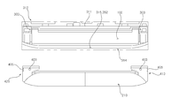
도 15는 도 1에서 흡입그릴이 분리된 상태의 프론트패널 저면도이다.
도 16은 도 15에서 베인모듈이 도시된 확대도이다.
도 17은 도 15에서 베인모듈이 분리된 상태의 프론트바디가 도시된 저면도이다.
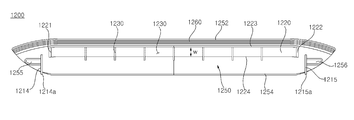
도 18은 도 10에 도시된 제 1 베인의 사시도이다.
도 19는 도 18의 평면도이다.
도 20은 도 18의 저면도이다.
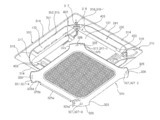
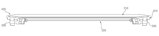
도 21은 도 18의 우측면도이다. 1 is a perspective view showing an air conditioner indoor unit according to an embodiment of the present invention.
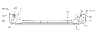
2 is a cross-sectional view of FIG. 1.
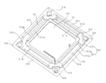
FIG. 3 is an exploded perspective view of the front panel of FIG. 1.
FIG. 4 is a perspective view showing an upper portion of the front panel of FIG. 1.
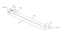
5 is a perspective view of the vane module shown in FIG. 3.
6 is a perspective view seen from another direction of FIG. 5.
7 is a perspective view of the vane module seen from the upper side of FIG. 5.
8 is a front view of the vane module shown in FIG. 3.
9 is a rear view of the vane module shown in FIG. 3.
10 is a plan view of the vane module shown in FIG. 3.
11 is a perspective view showing the operation structure of the vane module shown in FIG. 5.
12 is a front view of the drive link shown in FIG. 11.
13 is a front view of the first vane link shown in FIG. 11.
14 is a front view of the second vane link shown in FIG. 11.
15 is a bottom view of the front panel of the suction grill in FIG. 1;
16 is an enlarged view of the vane module shown in FIG. 15.
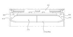
FIG. 17 is a bottom view of the front body in which the vane module is removed in FIG. 15.
18 is a perspective view of the first vane shown in FIG. 10.
19 is a plan view of FIG. 18.
20 is a bottom view of FIG. 18.
21 is a right side view of FIG. 18.
본 발명의 이점 및 특징, 그리고 그것들을 달성하는 방법은 첨부되는 도면과 함께 상세하게 후술되어 있는 실시예들을 참조하면 명확해질 것이다. 그러나 본 발명은 이하에서 개시되는 실시예들에 한정되는 것이 아니라 서로 다른 다양한 형태로 구현될 수 있으며, 단지 본 실시예들은 본 발명의 개시가 완전하도록 하고, 본 발명이 속하는 기술분야에서 통상의 지식을 가진 자에게 발명의 범주를 완전하게 알려주기 위해 제공되는 것이며, 본 발명은 청구항의 범주에 의해 정의될 뿐이다. 명세서 전체에 걸쳐 동일 참조 부호는 동일 구성 요소를 지칭한다.Advantages and features of the present invention, and methods for achieving them will be clarified with reference to embodiments described below in detail together with the accompanying drawings. However, the present invention is not limited to the embodiments disclosed below, but may be implemented in various different forms, and only the embodiments allow the disclosure of the present invention to be complete, and common knowledge in the technical field to which the present invention pertains. It is provided to completely inform the person having the scope of the invention, and the present invention is only defined by the scope of the claims. The same reference numerals refer to the same components throughout the specification.
이하 첨부된 도면을 참조하여 본 발명에 대해 구체적으로 살펴보기로 한다. Hereinafter, the present invention will be described in detail with reference to the accompanying drawings.
도 1은 본 발명의 일 실시예에 따른 공기조화기 실내기가 도시된 사시도이다. 도 2는 도 1의 단면도이다. 도 3은 도 1의 프론트패널이 도시된 분해사시도이다. 도 4는 도 1의 프론트패널 상부가 도시된 사시도이다. 도 5는 도 3에 도시된 베인모듈의 사시도이다. 도 6은 도 5의 다른방향에서 본 사시도이다. 도 7은 도 5의 상측에서 본 베인모듈의 사시도이다. 도 8은 도 3에 도시된 베인모듈의 정면도이다. 도 9는 도 3에 도시된 베인모듈의 배면도이다. 도 10은 도 3에 도시된 베인모듈의 평면도이다. 도 11은 도 5에 도시된 베인모듈의 작동구조가 도시된 사시도이다. 도 12는 도 11에 도시된 구동링크의 정면도이다. 도 13은 도 11에 도시된 제 1 베인링크의 정면도이다. 도 14는 도 11에 도시된 제 2 베인링크의 정면도이다. 도 15는 도 1에서 흡입그릴이 분리된 상태의 프론트패널 저면도이다. 도 16은 도 15에서 베인모듈이 도시된 확대도이다. 도 17은 도 15에서 베인모듈이 분리된 상태의 프론트바디가 도시된 저면도이다. 도 18은 도 10에 도시된 제 1 베인의 사시도이다. 도 19는 도 18의 평면도이다. 도 20은 도 18의 저면도이다. 도 21은 도 18의 우측면도이다. 1 is a perspective view showing an air conditioner indoor unit according to an embodiment of the present invention. 2 is a cross-sectional view of FIG. 1. FIG. 3 is an exploded perspective view of the front panel of FIG. 1. FIG. 4 is a perspective view showing an upper portion of the front panel of FIG. 1. 5 is a perspective view of the vane module shown in FIG. 3. 6 is a perspective view seen from another direction of FIG. 5. 7 is a perspective view of the vane module seen from the upper side of FIG. 5. 8 is a front view of the vane module shown in FIG. 3. 9 is a rear view of the vane module shown in FIG. 3. 10 is a plan view of the vane module shown in FIG. 3. 11 is a perspective view showing the operation structure of the vane module shown in FIG. 5. 12 is a front view of the drive link shown in FIG. 11. 13 is a front view of the first vane link shown in FIG. 11. 14 is a front view of the second vane link shown in FIG. 11. 15 is a bottom view of the front panel of the suction grill in FIG. 1; 16 is an enlarged view of the vane module shown in FIG. 15. FIG. 17 is a bottom view of the front body in which the vane module is removed in FIG. 15. 18 is a perspective view of the first vane shown in FIG. 10. 19 is a plan view of FIG. 18. 20 is a bottom view of FIG. 18. 21 is a right side view of FIG. 18.
<실내기의 구성><Composition of indoors>
본 실시예에 따른 공기조화기의 실내기는 흡입구(101) 및 토출구(102)가 형성된 케이스(100)와, 상기 케이스(100) 내부에 배치되는 실내열교환기(130)와, 상기 케이스(100) 내부에 배치되고, 상기 흡입구(101) 및 토출구(102)로 공기를 유동시키는 실내송풍팬(140)을 포함한다. The indoor unit of the air conditioner according to the present embodiment is a case 100 in which an
<케이스의 구성><Composition of the case>
본 실시예에서 상기 케이스(100)는 케이스하우징(110)과, 프론트패널(300)을 포함한다. 상기 케이스하우징(100)은 행거(미도시)를 통해 실내의 천장에 매달려 설치되고, 하측이 개구되어 형성된다. 상기 프론트패널(300)은 상기 케이스하우징(110)의 개구된 면을 커버하고, 실내의 바닥을 향해 배치되고, 실내에 노출되며, 상기 흡입구(101) 및 토출구(102)가 형성된다. In this embodiment, the case 100 includes a
상기 케이스(100)는 제작 형태에 따라 다양하게 구현될 수 있고, 상기 케이스(100)의 구성이 본 발명의 사상을 제한하지 않는다. The case 100 may be implemented in various ways depending on the production form, and the configuration of the case 100 does not limit the spirit of the present invention.
상기 흡입구(101)가 프론트패널(300)의 중앙에 배치되고, 상기 토출구(102)는 상기 흡입구(101)의 바깥쪽에 배치된다. 상기 흡입구(101)의 개수 또는 토출구(102)의 개수는 본 발명의 사상과 무관하다. 본 실시예에서 상기 흡입구(101)는 1개가 형성되고, 상기 토출구(102)는 복수개가 배치된다. The
본 실시예에서 상기 흡입구(101)는 저면에서 보았을 때 사각형 형상으로 형성되고, 상기 토출구(102)는 상기 흡입구(101)의 각 가장자리와 소정간격 이격되어 4개가 배치된다. In this embodiment, the
<실내열교환기의 구성><Configuration of indoor heat exchanger>
상기 실내열교환기(130)는 상기 흡입구(101) 및 토출구(102) 사이에 배치되고, 상기 실내열교환기(130)는 상기 케이스(100) 내부를 내측 및 외측으로 구획한다. 상기 실내열교환기(130)는 본 실시예에서 수직하게 배치된다.The
상기 실내열교환기(130)의 내측에 실내송풍팬(140)이 위치된다. An
상기 실내열교환기는 탑뷰 또는 바텀뷰로 볼 때, 전체적인 형상이 "□"로 형성되고, 일부구간은 분리될 수 있다. When viewed from the top or bottom view, the indoor heat exchanger has an overall shape of “□”, and some sections may be separated.
상기 실내열교환기(130)는 상기 실내송풍팬(140)에서 토출된 공기가 수직하게 진입하도록 배치된다. The
상기 케이스(100) 내부에 드레인팬(132)이 설치되고, 상기 실내열교환기(130)는 드레인팬(132)에 거치된다. 상기 실내열교환기(130)에서 생성된 응축수는 상기 드레인팬(132)으로 유동된 후 저장될 수 있다. 상기 드레인팬(132)에는 모인 응축수를 외부로 배출시키는 드레인펌프(미도시)가 배치된다. A
상기 드레인팬(132)은 실내열교환기(130)에서 흘러내린 응축수를 한쪽으로 모아 저장하기 위해 방향성을 갖는 경사면이 형성될 수 있다. The
<실내송풍팬의 구성><Composition of indoor ventilation fan>
상기 실내송풍팬(140)은 상기 케이스(100) 내부에 위치되고, 상기 흡입구(101) 상측에 배치된다. 상기 실내송풍팬(140)은 중앙으로 공기를 흡입하고 원주방향으로 공기를 토출하는 원심송풍기가 사용된다. The
상기 실내송풍팬(140)은 벨마우스(142), 팬(144) 및 팬모터(146)를 포함한다. The
상기 벨마우스(142)는 흡입그릴(320) 상측에 배치되고, 팬(144)의 하측에 위치된다. 상기 벨마우스(142)는 상기 흡입그릴(320)를 통과한 공기를 상기 팬(144)으로 안내한다. The
상기 팬모터(146)는 상기 팬(144)을 회전시킨다. 상기 팬모터(146)는 케이스하우징(110)에 고정된다. 상기 팬모터(146)는 상기 팬(144)의 상측에 배치된다. 상기 팬모터(146)의 적어도 일부분은 상기 팬(144)보다 높게 위치된다. The
상기 팬모터(146)의 모터축은 하측을 향해 배치되고, 상기 모터축에 상기 팬(144)이 결합된다. The motor shaft of the
상기 팬(144)의 가장자리 외측에 실내열교환기(130)가 위치된다. 상기 팬(144)과 실내열교환기(130)의 적어도 일부분은 동일 수평선상에 배치된다. 그리고 상기 벨마우스(142)의 적어도 일부분은 상기 팬(144)의 내측으로 삽입된다. 상하방향에 대해 상기 벨마우스(142)의 적어도 일부분은 상기 팬(144)과 오버랩된다. The
<유로의 구성><Composition of Euros>
상기 실내열교환기(130)는 케이스하우징(110)의 내부에 배치되고, 상기 케이스하우징(110) 내부 공간을 내측 및 외측으로 구획한다.The
상기 실내열교환기(130)로 둘러싸인 내측 공간을 흡입유로(103)로 정의하고, 상기 실내열교환기(130)의 외측 공간을 토출유로(104)로 정의한다. The inner space surrounded by the
상기 흡입유로(103)에 상기 실내송풍팬(140)이 배치된다. 상기 토출유로(104)는 실내열교환기(130)의 바깥쪽 및 케이스하우징(110)의 측벽 사이다. The
탑뷰 또는 바텀뷰로 볼때, 상기 흡입유로(103)는 실내열교환기의 "□"로 둘러싸인 내측이고, 토출유로(104)는 실내열교환기의 "□" 바깥쪽이다. When viewed in a top view or a bottom view, the
상기 흡입유로(103)는 흡입구(101)과 연통되고, 상기 토출유로(104)는 토출구(103)와 연통된다.The
공기는 상기 흡입유로(103)의 하측에서 상측으로 유동되고, 토출유로(104)의 상측에서 하측으로 유동된다. 상기 실내열교환기(130)를 기준으로 공기의 유동방향이 180도 전환된다. Air flows from the lower side of the
상기 흡입구(101) 및 토출구(102)는 프론트패널(300)의 같은 면에 형성된다.The
상기 흡입구(101) 및 토출구(102)는 같은 방향을 향하도록 배치된다. 본 실시예에서 상기 흡입구(101) 및 토출구(102)는 실내의 바닥을 향하도록 배치된다. The
상기 프론트패널(300)에 굴곡이 형성되는 경우 상기 토출구(102)가 약간의 측면경사를 갖게 형성될 수 있지만, 토출유로(104)와 연결된 토출구(102)는 하측을 향하도록 형성된다. In the case where the
상기 토출구(102)를 통해 토출되는 공기의 방향을 제어하기 위해 베인모듈(200)이 배치된다. A
<프론트패널의 구성><Configuration of front panel>
상기 프론트패널(300)은 케이스하우징(110)에 결합되고, 상기 흡입구(101) 및 토출구(102)가 형성된 프론트바디(310)와, 다수개의 그릴홀(321)이 형성되고, 상기 흡입구(101)를 커버하는 흡입그릴(320)과, 상기 흡입그릴(320)에 분리가능하게 조립되는 프리필터(330)와, 상기 프론트바디(310)에 설치되고, 상기 토출구(102)의 공기유동방향을 제어하는 베인모듈(200)을 포함한다. The
상기 흡입그릴(320)은 상기 프론트바디(310)에서 분리가능하게 설치된다. 상기 흡입그릴(320)은 상기 프론트바디(310)에서 상하 방향으로 엘리베이션될 수 있다. 상기 흡입그릴(320)은 상기 흡입구(101) 전체를 커버한다. The
본 실시예에서 상기 흡입그릴(320)는 격자형태를 통해 다수개의 그릴홀(321)이 형성된다. 상기 그릴홀(321)과 상기 흡입구(101)는 연통된다. In this embodiment, the
상기 흡입그릴(320)의 상측에 프리필터(330)가 배치된다. 상기 프리필터(330)는 상기 케이스(100) 내부로 흡입되는 공기를 여과한다. 상기 프리필터(330)는 상기 그릴홀(321) 상측에 위치되고, 상기 흡입그릴(320)을 통과한 공기를 여과한다. A pre-filter 330 is disposed above the
상기 토출구(102)는 상기 흡입구(101)의 가장자리를 따라 긴 슬릿의 형태로 형성된다. 상기 베인모듈(200)은 상기 토출구(102) 상에 위치되고, 상기 프론트바디(310)에 결합된다. The
본 실시예에서 상기 베인모듈(200)은 상기 프론트바디(310)의 하측으로 분리될 수 있다. 즉 상기 베인모듈(200)은 상기 프론트바디(310)의 결합구조와 무관하게 배치되고, 상기 프론트바디(310)에서 독립적으로 분리될 수 있다. 이에 관한 구조는 보다 상세하게 후술하겠다. In this embodiment, the
<프론트바디의 구성><Composition of front body>
상기 프론트바디(310)는 케이스하우징(110)의 하측에 결합되고, 실내의 방향을 향해 배치된다. 상기 프론트바디(310)는 실내의 천장에 설치되고, 실내에 노출된다. The
상기 프론트바디(310)는 케이스하우징(110)에 결합되고, 상기 케이스하우징(110)은 상기 프론트바디(310)의 하중을 지지한다. 상기 프론트바디(310)는 흡입그릴(320) 및 프리필터(330)의 하중을 지지한다. The
상기 프론트바디(310)는 탑뷰로 볼 때, 사각형 형상으로 형성된다. 상기 프론트바디(310)의 형상은 다양하게 형성될 수 있다. The
상기 프론트바디(310)의 상측면은 천장에 밀착될 수 있도록 수평하게 형성되고, 하측면은 가장자리가 약간의 곡면을 형성할 수 있다. The upper side of the
상기 프론트바디(310)의 중앙에 흡입구(101)가 배치되고, 상기 흡입구(101) 가장자리 바깥쪽에 복수개의 토출구(102)가 배치된다.A
탑뷰로 볼 때, 상기 흡입구(101)는 정사각형 형상으로 형성되고, 토출구(102)는 직사각형 형상으로 형성될 수 있다. 상기 토출구(102)는 폭보다 길이가 긴 슬릿형태로 형성될 수 있다. When viewed in a top view, the
상기 프론트바디(310)는 프론트프레임(312), 사이드커버(314), 코너커버(316)를 포함한다.The
상기 프론트프레임(312)은 프론트패널(300)의 하중 및 강성을 제공하고, 상기 케이스하우징(110)에 체결고정된다. 상기 프론트프레임(312)에 상기 흡입구(101) 및 4개의 토출구(102)가 형성된다.The
본 실시예에서 상기 프론트프레임(312)은 사이드프레임(311) 및 코너프레임(313)을 포함한다. In this embodiment, the
상기 코너프레임(313)은 프론트패널(300)의 각 모서리에 배치된다. 상기 사이드프레임(311)은 2개의 코너프레임(313)과 결합된다. 상기 사이드프레임(311)은 이너 사이드프레임(311a) 및 아우터 사이드프레임(311b)를 포함한다. The
상기 이너 사이드프레임(311a)은 흡입구(101) 및 토출구(102) 사이에 배치되고, 2개의 코너프레임(313)을 결합시킨다. 아우터 사이드프레임(311b)은 토출구(102)의 바깥쪽에 배치된다. The
본 실시예에서는 4개의 이너 사이드프레임(311a) 및 4개의 아우터 사이드프레임(311b)이 구비된다. In this embodiment, four
상기 흡입구(101)는 4개의 이너 사이드프레임(311a) 내측에 위치된다. 상기 토출구(102)는 2개의 코너프레임(313), 이너 사이드프레임(311a) 및 아우터 사이드프레임(311b)에 둘러싸여 형성된다. The
그리고 상기 프론트프레임(312)의 저면에 상기 사이드커버(314) 및 코너커버(316)가 결합된다. 상기 사이드커버(314) 및 코너커버(316)는 사용자에게 노출되고, 상기 프론트프레임(312)은 사용자에게는 보이지 않는다. In addition, the
상기 사이드커버(314)는 상기 프론트프레임(312)의 가장자리에 배치되고, 상기 코너커버(316)는 상기 프론트프레임(312)의 모서리에 배치된다. The
상기 사이드커버(314)는 합성수지 재질로 형성되고, 상기 프론트프레임(312)에 체결고정된다. 구체적으로 상기 사이드커버(314)는 상기 사이드프레임(311)에 결합되고, 코너커버(316)는 코너프레임(313)에 결합된다. The
본 실시예에서 상기 사이드커버(314) 및 코너커버(316)는 각각 4개가 구비된다. 상기 사이드커버(314) 및 코너커버(316)는 상기 프론트프레임(312)에 결합되어 하나의 구조물로 연결된다. 상기 프론트패널(300)에서 4개의 사이드커버(314) 및 4개의 코너커버(316)는 하나의 가장자리를 형성한다.In this embodiment, four of the
상기 사이드프레임(311) 하측에 상기 사이드커버(314)가 배치되고, 코너프레임(313) 하측에 상기 코너커버(316)가 배치된다. The
4개의 사이드커버(314) 및 4개의 코너커버(316)는 조립되어 4각형의 테두리를 형성한다. 연결된 4개의 사이드커버(314) 및 4개의 코너커버(316)를 프론트데코(350)라고 정의한다. The four side covers 314 and the four corner covers 316 are assembled to form a quadrangular rim. The four connected side covers 314 and the four corner covers 316 are defined as a
상기 프론트데코(350)는 데코 아우터보더(351, outer border)와 데코 이너보더(352, inner border)를 형성한다. The
탑뷰 또는 바텀뷰로 볼 때, 상기 데코 아우터보더(351)는 사각형으로 형성되고, 데코 이너보더(352)도 전체적인 형상은 사각형으로 형성된다. 다만 상기 데코 이너보더의 모서리는 소정의 곡률을 형성한다. When viewed from a top view or a bottom view, the deco
상기 데코 이너보더(352) 내측에 상기 흡입그릴(320) 및 4개의 베인모듈(200)이 배치된다. 그리고 상기 데코 이너보더(352)에 흡입그릴(320) 및 4개의 베인모듈(200) 접한다. The
본 실시예에서 상기 사이드커버(314)는 4개가 배치되고, 각 사이드커버(314)는 상기 프론트프레임(312)에 결합된다. 상기 사이드커버(314)의 바깥쪽 가장자리는 상기 데코 아우터보더(351)의 일부를 형성하고, 안쪽 가장자리는 상기 데코 이너보더(352)의 일부를 형성한다.In this embodiment, four side covers 314 are disposed, and each
특히, 상기 사이드커버(314)의 안쪽 가장자리는 상기 토출구(102)의 바깥쪽 경계를 형성한다. 상기 사이드커버(314)의 안쪽 가장자리를 사이드데코 이너보더(315)로 정의한다.In particular, the inner edge of the
본 실시예에서 상기 코너커버(316)는 4개가 배치되고, 각 코너커버(316)는 상기 프론트프레임(312)에 결합된다. 상기 코너커버(316)의 바깥쪽 가장자리는 상기 데코 아우터보더(351)의 일부를 형성하고, 안쪽 가장자리는 상기 데코 이너보더(352)의 일부를 형성한다.In this embodiment, four corner covers 316 are disposed, and each
상기 코너커버(316)의 안쪽 가장자리를 코너데코 이너보더(317)로 정의한다.The inner edge of the
상기 코너데코 이너보더(317)는 상기 흡입그릴(320)과 맞닿게 배치될 수 있다. 본 실시예에서는 상기 코너커버(316)의 안쪽 가장자리는 상기 흡입그릴(320)과 마주보게 배치되고, 소정간격 이격되어 갭(317a)을 형성한다. The corner deco
상기 사이드데코 이너보더(315) 역시 상기 베인모듈(200)과 소정간격 이격되어 갭(315a)을 형성하고, 상기 베인모듈(200)의 바깥쪽 가장자리와 마주보게 배치된다. The side deco inner border 315 is also spaced a predetermined distance from the
그래서 상기 데코 이너보더(352)는 4개의 베인모듈(200) 및 흡입그릴(320)의 바깥쪽 가장자리와 소정간격 이격되고 연속된 갭을 형성한다. Therefore, the decor inner border 352 forms a continuous gap spaced apart from the outer edges of the four
4개의 사이드데코 이너보더 갭(315a) 및 4개의 코너데코 이너보더 갭(317a)에 의해 형성된 연속된 갭을 프론트데코 갭(350a)으로 정의한다. The continuous gap formed by the four side deco
상기 프론트데코 갭(350a)은 상기 프론트데코(350)의 안쪽 가장자리에 형성된다. 구체적으로 상기 프론트데코 갭(350a)은 베인모듈(200) 및 흡입그릴(320)의 바깥쪽 가장자리와 프론트데코(350)의 안쪽 가장자리가 이격되어 형성된다. The
상기 베인모듈(200)이 작동되지 않을 때(실내기 정지 시), 상기 프론트데코 갭(350a)은 흡입그릴(320) 및 베인모듈(200)을 하나의 구조물로 보이게 한다. When the
<흡입그릴의 구성><Structure of suction grill>
상기 흡입그릴(320)은 프론트바디(310)의 하측에 위치된다. 상기 흡입그릴(320)은 상기 프론트바디(310)의 저면에 밀착된 상태에서 하측으로 승강될 수 있다.The
상기 흡입그릴(320)은 그릴바디(322)와, 상기 그릴바디(322)를 상하방향으로 관통하게 형성된 다수개의 그릴홀(321)을 포함한다. The
상기 흡입그릴(320)은, 상기 흡입구(101)의 하측에 배치되고, 다수개의 그릴홀(321)에 의해 상기 흡입구(101)와 연통되고, 사각형 형상으로 형성된 그릴바디(322)과, 상기 그릴바디(322)의 모서리에서 대각선방향으로 연장되어 형성된 그릴코너부(327)를 포함한다. The
상기 그릴바디(322)의 저면과 제 1 베인(1200)의 저면은 연속된 면을 형성할 수 있다. 또한, 상기 그릴바디(322)의 저면과 코너커버(316)의 저면은 연속된 면을 형성할 수 있다.The bottom surface of the grill body 322 and the bottom surface of the
상기 그릴바디(322)의 내측에는 다수개의 그릴(323)이 격자형태로 배치된다. 상기 격자형태의 그릴(323)은 사각형 형태의 그릴홀(321)을 형성시킨다. 상기 그릴(323) 및 그릴홀(321)이 형성된 부분을 흡입부로 정의한다. A plurality of grills 323 are disposed inside the grill body 322 in a grid shape. The grid-shaped grill 323 forms a
상기 그릴바디(322)는 공기가 소통되는 흡입부와, 상기 흡입부를 둘러싸게 배치되는 그릴바디부(324)를 포함한다. 탑뷰 또는 바텀뷰로 볼때, 상기 흡입부는 전체적인 형상이 사각형으로 형성된다. The grill body 322 includes a suction portion through which air is communicated, and a grill body portion 324 disposed to surround the suction portion. When viewed in a top view or a bottom view, the suction part is formed in a rectangular shape as a whole.
상기 흡입부의 각 모서리는 프론트패널(300)의 각 모서리를 향하게 배치되고, 보다 상세하게는 상기 코너커버(316)를 향하게 배치된다. Each corner of the suction part is disposed toward each corner of the
바텀뷰로 볼 때, 상기 그릴바디(322)는 사각형 형상으로 형성된다.When viewed from the bottom view, the grill body 322 is formed in a rectangular shape.
상기 그릴바디부(324)의 외측 가장자리는 상기 토출구(102) 또는 프론트데코(350)와 마주보게 배치된다. The outer edge of the grill body portion 324 is disposed to face the
상기 그릴바디부(324)의 외측 가장자리는 코너커버(316)와 마주보게 배치되는 그릴 코너보더(326)와, 상기 토출구(102)를 형성하고, 상기 사이드커버(314)와 마주보게 배치되는 그릴 사이드보더(325)를 포함한다. The outer edge of the grill body portion 324 is a
상기 그릴 코너보더(326)는 흡입그릴(320)의 내측을 중심으로 하는 곡률로 형성되고, 그릴 사이드보더(325)는 상기 흡입그릴(320)의 외측을 중심으로 곡률로 형성될 수 있다.The
상기 그릴바디부(324)는 상기 그릴 코너보더(326) 및 2개의 그릴 사이드보더(325)에 의해 감싸지는 그릴코너부(327)를 더 포함한다. 상기 그릴코너부(327)는 그릴바디부(324)에서 코너커버(316) 측으로 돌출되어 형성된다. The grill body portion 324 further includes a grill corner portion 327 wrapped by the
상기 그릴코너부(327)는 상기 그릴바디(322)의 각 모서리에 배치된다. 상기 그릴코너부(327)는 상기 프론트패널(300)의 각 모서리를 향해 연장된다. The grill corner portion 327 is disposed at each corner of the grill body 322. The grill corner portion 327 extends toward each corner of the
본 실시예에서 상기 그릴코너부(327)는 4개가 배치된다. 설명의 편의를 위해 4개의 그릴코너부(327)를 제 1 그릴코너부(327-1), 제 2 그릴코너부(327-2), 제 3 그릴코너부(327-3) 및 제 4 그릴코너부(327-4)라 정의한다.In this embodiment, four grill corner portions 327 are arranged. For convenience of description, the four grill corner portions 327 are the first grill corner portion 327-1, the second grill corner portion 327-2, the third grill corner portion 327-3 and the fourth grill. It is defined as the corner portion 327-4.
상기 그릴 사이드보더(325)는 바깥쪽에서 안쪽으로 오목한 형상으로 형성된다.The
상기 사이드커버(314) 및 흡입그릴(320) 사이에 토출구(102)가 형성된다. 보다 구체적으로는 상기 사이드커버(314)의 사이드데코 이너보더(315) 및 그릴바디(322)의 그릴사이드보더(325) 사이에 1개의 토출구(102)가 형성된다. 상기 흡입그릴(320)의 4방향에 배치된 사이드데코 이너보더(315) 및 그릴사이드보더(325) 사이에 각각의 토출구(102)가 형성된다. The
본 실시예에서 그릴 코너보더(326)의 길이와 코너데코 이너보더(317)의 길이는 갖게 형성된다. 즉, 상기 코너커버(316)의 폭과 상기 그릴코너부(327)의 폭이 같게 형성된다. In this embodiment, the length of the
그리고 사이드커버(314)의 내측 폭과 그릴 사이드보더(325)의 폭이 같게 형성된다. And the inner width of the
상기 그릴 사이드보더(325)를 보다 상세하게 구분하면 다음과 같다. The
상기 그릴 사이드보더(325)는 상기 토출구(102)의 안쪽 경계를 형성한다. 상기 사이드데코 이너보더(315) 및 코너데코 이너보더(317)는 상기 토출구(102)의 바깐쪽 경계를 형성한다. The
상기 그릴 사이드보더(325)는 토출구(102)의 길이 방향으로 길게 연장되고, 직선으로 형성된 긴직선구간(325a)과, 상기 긴직선구간(325a)의 일측과 연결되고, 상기 흡입그릴(320)의 바깥쪽에 곡률중심이 형성되는 제 1 곡선구간(325b)과, 상기 긴직선구간(325a)의 타측과 연결되고, 상기 흡입그릴(320)의 바깥쪽에 곡률중심이 형성되는 제 2 곡선구간(325c)과, 상기 제 1 곡선구간(325b)과 연결되는 제 1 짧은직선구간(325d)과, 상기 제 2 곡선구간(325c)과 연결되는 제 2 짧은직선구간(325e)을 포함한다. The
<베인모듈의 구성><Composition of vane module>
상기 베인모듈(200)은 토출유로(104)에 설치되고, 상기 토출구(102)를 통해 토출되는 공기의 유동방향을 제어한다.The
상기 베인모듈(200)은 모듈바디(400)와, 제 1 베인(1200), 제 2 베인(220), 베인모터(230), 구동링크(240), 제 1 베인링크(250) 및 제 2 베인링크(260)를 포함한다. The
상기 제 1 베인(1200), 제 2 베인(220), 베인모터(230), 구동링크(240), 제 1 베인링크(250) 및 제 2 베인링크(260)는 모두 모듈바디(400)에 설치된다. 상기 모듈바디(400)는 상기 프론트패널(300)에 일체로 설치된다. 즉, 상기 베인모듈(200)의 구성부품 전체는 모듈화되고, 상기 프론트패널(300)에 한번에 설치된다. The
상기 베인모듈(200)이 모듈화되기 때문에, 조립시간을 단축시킬 수 있고, 고장 시 교체가 용이한 장점이 있다. Since the
본 실시예에서 상기 베인모터(230)는 스텝모터가 사용된다. In this embodiment, the
<모듈바디의 구성><Configuration of module body>
상기 모듈바디(400)는 하나의 바디로 구성될 수 있다. 본 실시예에서는 설치공간을 최소화하고, 제작비용을 최소화하기 위해 2개의 부품으로 분리하여 제작한다.The module body 400 may be configured as one body. In this embodiment, to minimize the installation space and to minimize the manufacturing cost, it is manufactured by separating into two parts.
본 실시예에서 상기 모듈바디(400)는 제 1 모듈바디(410) 및 제 2 모듈바디(420)로 구성된다.In this embodiment, the module body 400 is composed of a
상기 제 1 모듈바디(410) 및 제 2 모듈바디(420)는 좌우 대칭으로 형성된다. 본 실시예에서는 공통의 구성에 대해서는 상기 제 1 모듈바디(410)를 예로 들어 설명한다. The
상기 제 1 모듈바디(410) 및 제 2 모듈바디(420)는 각각 상기 프론트바디(310)에 체결된다. 구체적으로 상기 제 1 모듈바디(410) 및 제 2 모듈바디(420)는 각각 코너프레임(313)에 설치된다. The
수평방향에 대해 상기 제 1 모듈바디(410)는 토출구(102)의 일측에 배치된 코너프레임(313)에 설치되고, 상기 제 2 모듈바디(420)는 토출구(102)의 타측에 배치된 코너프레임(313)에 설치된다. With respect to the horizontal direction, the
상하방향에 대해, 상기 제 1 모듈바디(410) 및 제 2 모듈바디(420)는 각각의 코너프레임(313)의 저면에 밀착되고, 체결부재(401)를 통해 각각 체결된다. With respect to the vertical direction, the
그래서 상기 제 1 모듈바디(410) 및 제 2 모듈바디(420)는 상기 프론트바디(310)의 하측에 배치된다. 실내기의 설치된 상태로 볼 때, 상기 제 1 모듈바디(410) 및 코너프레임(313)의 체결방향은 하측에서 상측을 향하도록 배치되고, 상기 제 2 모듈바디(420) 및 코너프레임(313)의 체결방향 역시 하측에서 상측을 향하도록 배치된다. Thus, the
이와 같은 구조로 인해, 서비스과정에서 상기 베인모듈(200) 전체를 상기 프론트바디(310)에서 용이하게 분리할 수 있다. Due to such a structure, the
상기 베인모듈(200)은, 상기 토출구(102)의 일측에 배치되고, 상기 프론트바디(310)의 하측에 위치되고, 상기 프론트바디(310)에 대해 하측으로 분리가능하게 조립된 제 1 모듈바디(410)와, 상기 토출구(102)의 타측에 배치되고, 상기 프론트바디(310)의 하측에 위치되고, 상기 프론트바디(310)에 대해 하측으로 분리가능하게 조립된 제 2 모듈바디(420)와, 일측 및 타측이 상기 제 1 모듈바디(410) 및 제 2 모듈바디(420)와 각각 결합되고, 상기 제 1 모듈바디(410) 및 제 2 모듈바디(420)에 대해 상대회전되는 적어도 하나 이상의 베인(1200)(220)과, 상기 제 1 모듈바디(410) 또는 제 2 모듈바디(420) 중 적어도 어느 하나에 설치되고, 상기 베인에 구동력을 제공하는 베인모터(230)과, 상기 제 1 모듈바디(410)에 배치되고, 하측을 향하게 배치되고, 상기 제 1 모듈바디(410)를 관통하게 형성되는 제 1 체결홀(403-1)과, 상기 제 1 체결홀(403-1)을 통해 상기 프론트바디(310)에 체결되는 제 1 체결부재(401-1)과, 상기 제 2 모듈바디(420)에 배치되고, 하측을 향하게 배치되고, 상기 제 2 모듈바디(420)를 관통하게 형성되는 제 2 체결홀(403-2)과, 상기 제 2 체결홀(403-2)을 통해 상기 프론트바디에 체결되는 제 2 체결부재(401-2)를 포함한다. The
특히 상기 제 1 모듈바디(410) 및 제 2 모듈바디(420)가 프론트바디(310)의 하측에 위치되기 때문에, 상기 프론트바디(310)가 케이스하우징(110)에 설치된 상태에서 상기 베인모듈(200)만을 프론트바디(310)에서 분리할 수 있다. 이는 4개소의 베인모듈(200) 모두에 대해 공통적으로 적용된다. In particular, since the
상기 모듈바디(400)를 프론트바디(310)에서 분리할 경우, 상기 베인모듈(200) 전체는 프론트바디(310)의 하측으로 분리된다. When the module body 400 is separated from the
상기 제 1 모듈바디(410)는 상기 프론트바디(310)에 결합되는 모듈바디부(402)와, 상기 모듈바디부(402)에서 상측으로 돌출되는 링크설치부(404)를 포함한다. The
상기 모듈바디부(402)는 체결부재(401)(미도시)에 의해 상기 프론트바디(310)에 체결된다. 본 실시예와 달리 상기 모듈바디부(402)는 후크결합 또는 억지끼움등을 통해 프론트바디(310)에 결합될 수 있다. The
본 실시예에서는 제 1 베인(1200), 제 2 베인(220), 베인모터(230), 구동링크(240), 제 1 베인링크(250) 및 제 2 베인링크(260) 등에 의한 진동 또는 소음발생을 최소화시키기 위해 상기 모듈바디부(402)를 프론트바디(310)에 견고하게 체결한다. In this embodiment, the vibration or noise caused by the
상기 모듈바디부(402)를 고정시키는 체결부재(401)는 하측에서 상측 방향으로 체결된 상태이고, 상측에서 하측으로 분리될 수 있다. The fastening member 401 for fixing the
상기 모듈바디부(402)에는 체결부재(401)가 관통되는 체결홀(403)이 형성된다.A
설명의 편의를 위해, 상기 제 1 모듈바디(410)에 형성된 체결홀과 제 2 모듈바디(420)에 형성된 체결홀을 구분할 필요가 있을 때, 상기 제 1 모듈바디(410)에 배치된 체결홀을 제 1 체결홀(403-1)이라 하고, 상기 제 2 모듈바디(420)에 배치된 체결홀을 제 2 체결홀(403-1)이라 한다. For convenience of description, when it is necessary to distinguish the fastening hole formed in the
그리고 체결부재(401)를 구분할 필요가 있을 경우, 상기 제 1 체결홀(403-1)에 설치되는 체결부재(401)를 제 1 체결부재(401-1)라 정의하고, 상기 제 2 체결홀(403-1)에 설치되는 체결부재(401)를 제 2 체결부재(401-2)라 정의한다.And when it is necessary to distinguish the fastening member 401, the fastening member 401 installed in the first fastening hole 403-1 is defined as a first fastening member 401-1, and the second fastening hole The fastening member 401 installed in 403-1 is defined as a second fastening member 401-2.
상기 제 1 체결부재(401-1)는 상기 제 1 체결홀을 관통하고, 프론트바디(310)에 체결된다. 상기 제 2 체결부재(401-2)는 상기 제 2 체결홀을 관통하고, 프론트바디(310)에 체결된다.The first fastening member 401-1 penetrates the first fastening hole and is fastened to the
상기 모듈바디(400)를 체결고정하기 전에, 상기 모듈바디(400)의 위치를 임시 고정하기 위한 모듈후크(405)가 배치된다. Before fastening and fixing the module body 400, a
상기 모듈후크(405)는 프론트패널(300, 구체적으로 프론트바디(310))과 결합됩니다. 구체적으로 상기 모듈후크(405) 및 프론트바디(310)는 상호 걸림을 형성한다.The
하나의 모듈바디에 복수개의 모듈후크(405)가 배치될 수 있다. 본 실시예에서는 상기 모듈바디부(402)의 바깥쪽 가장자리 및 전방 측 가장자리에 각각 배치된다. 즉 제 1 모듈바디(410) 및 제 2 모듈바디(420)의 바깥쪽에 각각 모듈후크(405)가 배치되고, 각 모듈후크(405)는 좌우방향에 대해 대칭된다. A plurality of module hooks 405 may be disposed on one module body. In this embodiment, the
상기 제 1 모듈바디(410) 모듈후크(405) 및 제 2 모듈바디(420)의 모듈후크(405)에 의해 상기 베인모듈(200)을 프레임바디(310)에 임시고정시킬 수 있다. The
상기 모듈후크(405)들에 의한 고정은 결합구조 상 약간의 유격이 발생될 수 있다. 체결부재(401)는 임시고정된 상기 모듈바디(400)를 프론프바디(310)에 견고하게 고정시킨다. Fixing by the module hooks 405 may cause a slight play on the coupling structure. The fastening member 401 firmly fixes the temporarily fixed module body 400 to the
상기 체결부재(401)가 설치되는 체결홀(403)은 상기 모듈후크(405)들 사이에 위치될 수 있다. 일측 및 타측의 모듈후크(405)들 사이에 제 1 모듈바디(410)의 체결홀(403) 및 제 2 모듈바디(420)의 체결홀(403)이 배치된다. The
본 실시예에서 모듈후크(405)들 및 체결홀(403)들은 일렬로 배치된다. In this embodiment, the module hooks 405 and the fastening holes 403 are arranged in a line.
상기 체결부재(401)들이 해체되어도, 상기 모듈후크(405)들에 의해 베인모듈(200)이 상기 프레임바디(310)에 결합된 상태를 유지할 수 있다. Even when the fastening members 401 are disassembled, the
수리 또는 고장 시, 상기 베인모듈(200)을 분리할 필요가 있을 때, 상기 체결부재(401)를 분리하여도 상기 베인모듈(200)은 프론트패널(300)에 결합된 상태를 유지한다. 이로 인해 작업자는 상기 체결부재(401)의 해체 시, 상기 베인모듈(200)을 별도로 지지할 필요가 없다. When repairing or malfunctioning, when it is necessary to separate the
상기 베인모듈(200)은 모듈후크(405)에 의한 1차 고정 및 체결부재(401)에 의한 2차고정이 이루어지기 때문에, 서비스 시 작업편의성을 대폭 향상시킬 수 있다. Since the
상기 모듈바디부(402)는 수평하게 배치되고, 상기 링크설치부(404)는 수직하게 배치된다. 특히 상기 링크설치부(404)는 설치된 상태로 볼 때, 상기 모듈바디부(402)에서 상측으로 돌출된다. The
상기 제 1 모듈바디(410)의 링크설치부(404) 및 제 2 모듈바디(420)의 링크설치부(404)는 서로 마주보게 배치된다. 상기 제 1 모듈바디(410)의 링크설치부(404) 및 제 2 모듈바디(420)의 링크설치부(404) 사이에 제 1 베인(1200), 제 2 베인(220), 구동링크(240), 제 1 베인링크(250) 및 제 2 베인링크(260)가 설치된다. 상기 베인모터(230)는 상기 제 1 모듈바디(410)의 링크설치부(404)의 바깥쪽 또는 상기 제 2 모듈바디(420)의 링크설치부(404)의 바깥쪽에 배치된다. The
상기 베인모터(230)는 상기 제 1 모듈바디(410) 또는 제 2 모듈바디(420) 중 어느 하나에만 설치될 수 있다. 본 실시예에서는 상기 제 1 모듈바디(410) 또는 제 2 모듈바디(420)에 각각 배치된다. The
상기 제 1 모듈바디(410) 및 제 2 모듈바디(420) 사이에 제 1 베인(1200), 제 2 베인(220), 구동링크(240), 제 1 베인링크(250) 및 제 2 베인링크(260)가 결합되어 상기 베인모듈(200)이 일체화된다. A
상기 베인모터(230)를 설치하기 위해, 상기 링크설치부(404)의 바깥쪽으로 돌출된 베인모터설치부(406)가 배치된다. 상기 베인모터설치부(406)에 상기 베인모터(230)가 체결고정된다. 상기 베인모터설치부(406)는 보스형태로 형성되고, 상기 베인모터(230)는 상기 베인모터설치부(406)에 고정된다. 베인모터설치부(406)로 인해 상기 링크설치부(404) 및 베인모터(230)는 소정간격 이격된다. In order to install the
상기 링크설치부(404)에는 상기 구동링크(240)가 조립되고, 상기 구동링크(240)에 회전중심을 제공하는 구동링크결합부(407)와, 상기 제 1 베인링크(250)가 조립되고 상기 제 1 베인링크(250)에 회전중심을 제공하는 제 1 베인링크결합부(408)와, 상기 제 2 베인(220)과 결합되고 상기 제 2 베인(220)에 회전중심을 제공하는 제 2 베인결합부(409)가 배치된다. The
본 실시예에서 구동링크결합부(407), 제 1 베인링크결합부(408) 및 제 2 베인결합부(409)는 홀 형태로 형성된다. 본 실시예와 달리 보스 형태로 형성될 수도 있고, 회전축을 제공하는 다양한 형태로 구현될 수 있다. In this embodiment, the drive
한편, 상기 링크설치부(404)에는 상기 구동링크(240)의 회전각을 제한하는 스토퍼(270)가 배치된다. 상기 스토퍼(270)는 반대편 링크설치부(404)를 향해 돌출되어 배치된다. Meanwhile, a
본 실시예에서 상기 스토퍼(270)는 상기 구동링크(240)의 회전 시 특정위치에서 간섭을 발생시키고, 상기 구동링크(240)의 회전을 제한한다. 상기 스토퍼(270)는 상기 구동링크(240)의 회전반경 내에 위치된다. In this embodiment, the
본 실시예에서 상기 스토퍼(270)는 상기 링크설치부(404)와 일체로 제작된다. 본 실시예에서 상기 스토퍼(270)는 상기 구동링크(240)의 설치위치를 제공하고, 상기 구동링크(240)의 회전 시 접촉된 상태를 유지하며, 상기 구동링크(240)의 진동 또는 유격을 억제한다. In this embodiment, the
본 실시예에서 상기 스토퍼(270)는 호 형상으로 형성된다. In this embodiment, the
<구동링크의 구성><Composition of drive link>
상기 구동링크(240)는 베인모터(230)와 직접 연결된다. 상기 베인모터(230)의 모터축(미도시)은 상기 구동링크(240)에 직접 결합되고, 상기 베인모터(230) 회전축의 회전각도에 따라 상기 구동링크(240)의 회전량이 결정된다.The
상기 구동링크(240)는 상기 링크설치부(404)를 관통하여 상기 베인모터(230)에 조립된다. 본 실시예에서 상기 구동링크(240)는 구동링크결합부(407)를 관통한다. The driving
상기 구동링크(240)는 구동링크바디(245)와, 상기 구동링크바디(245)에 배치되고, 상기 제 1 베인(1200)와 회전가능하게 결합되는 제 1 구동링크축(241)과, 상기 구동링크바디(245)에 배치되고, 상기 링크설치부(404, 구체적으로 구동링크결합부(407))에 회전가능하게 결합되는 코어링크축(243)과, 상기 구동링크바디(245)에 배치되고, 상기 제 2 베인링크(260)와 회전가능하게 결합되는 제 2 구동링크축(242)을 포함한다. The
상기 구동링크바디(245)는 제 1 구동링크바디(246), 제 2 구동링크바디(247) 및 코어바디(248)를 포함한다.The
상기 코어바디(248)에 상기 코어링크축(243)이 배치되고, 상기 제 1 구동링크바디(246)에 상기 제 1 구동링크축(241)이 배치되고, 상기 제 2 구동링크바디(247)에 상기 코어링크축(243)이 배치된다. The
상기 코어바디(248)는 제 1 구동링크바디(246) 및 제 2 구동링크바디(247)를 연결한다. 상기 제 1 구동링크바디(246) 및 제 2 구동링크바디(247)의 형상에 특별한 제약은 없다. 다만, 본 실시예에서 제 1 구동링크바디(246) 및 제 2 구동링크바디(247)는 대체적으로 직선의 형태로 형성된다. The
상기 제 1 구동링크바디(246)는 제 2 구동링크바디(247) 보다 길게 형성된다. The first
상기 코어링크축(243)은 상기 링크설치부(404)와 회전가능하게 조립된다. 상기 코어링크축(243)은 상기 링크설치부(404)에 형성된 구동링크결합부(407)에 조립된다. 상기 코어링크축(243)은 상기 구동링크결합부(407)와 결합된 상태에서 상대회전될 수 있다. The
상기 제 1 구동링크축(241)은 제 1 베인(1200)과 회전가능하게 조립된다. 상기 제 2 구동링크축(242)은 상기 제 2 베인링크(260)와 회전가능하게 조립된다. The first
상기 제 1 구동링크축(241) 및 제 2 구동링크축(242)은 같은 방향으로 돌출된다. 상기 코어링크축(243)은 상기 제 1 구동링크축(241) 및 제 2 구동링크축(242)과 반대방향으로 돌출된다. The first
상기 제 1 구동링크바디(246) 및 제 2 구동링크바디(247)는 소정의 사이각을 형성한다. 상기 제 1 구동링크축(241) 및 코어링크축(243)을 연결하는 가상의 직선과 상기 코어링크축(243) 및 제 2 구동링크축(242)을 연결하는 가상의 직선은 소정의 사이각(E)을 형성한다. 상기 사이각(E)은 0도 초과 180도 미만으로 형성된다. The first
상기 제 1 구동링크축(241)은 상기 구동링크바디(245)와 제 1 베인(1200)이 상대회전될 수 있는 구조를 제공한다. 본 실시예에서 상기 제 1 구동링크축(241)은 상기 구동링크바디(245)와 일체로 형성된다. 본 실시예와 달리 상기 제 1 구동링크축(241)은 상기 제 1 베인(1200) 또는 조인트(1214)와 일체로 제작될 수 있다. The first
상기 코어링크축(243)은 상기 구동링크바디(245) 및 모듈바디(구체적으로 링크설치부(404))가 상대회전될 수 있는 구조를 제공한다. 본 실시예에서 상기 코어링크축(243)은 상기 구동링크바디(245)와 일체로 형성된다. The
상기 제 2 구동링크축(242)은 상기 제 2 베인링크(260) 및 구동링크(240)가 상대회전될 수 있는 구조를 제공한다. 본 실시예에서 상기 제 2 구동링크축(242)은 상기 구동링크바디(245)와 일체로 형성된다. 본 실시예와 달리 상기 제 2 구동링크축(242)은 상기 제 2 베인링크(260)와 일체로 제작될 수 있다. The second
본 실시예에서 상기 제 2 구동링크축(242)은 상기 제 2 구동링크바디(247)에 배치된다. 상기 제 2 구동링크축(242)는 상기 코어링크축(243)을 기준으로 상기 제 1 구동링크축(241)의 반대편에 배치된다. In this embodiment, the second
상기 제 1 구동링크축(241) 및 코어링크축(243)을 연결하는 가상의 직선과 상기 코어링크축(243) 및 제 2 구동링크축(242)을 연결하는 가상의 직선은 소정의 사이각(E)을 형성한다. 상기 사이각(E)은 0도 초과 180도 미만으로 형성된다. The virtual straight line connecting the first
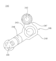
<제 1 베인링크의 구성><Composition of the first vane link>
본 실시예에서 상기 제 1 베인링크(250)는 견고한 재질로 형성되고, 직선의 형태로 형성된다. 본 실시예와 달리 상기 제 1 베인링크(250)는 곡선으로 형성될 수 있다. In this embodiment, the
상기 제 1 베인링크(250)는 제 1 베인링크바디(255)와, 상기 제 1 베인링크바디(255)에 배치되고, 상기 제 1 베인(1200)과 조립되고, 상기 제 1 베인(1200)과 상대 회전되는 제 1-1 베인링크축(251)과, 상기 제 1 베인링크바디(255)에 배치되고, 상기 모듈바디(400, 구체적으로 링크설치부(404))와 조립되고, 상기 모듈바디(400)와 상대 회전되는 제 1-2 베인링크축(252)을 포함한다. The
상기 제 1-1 베인링크축(251)은 제 1 베인(1200) 측으로 돌출된다. 상기 제 1-1 베인링크축(251)은 상기 제 1 베인(1200)과 조립되고, 상기 제 1 베인(1200)과 상대회전될 수 있다. The 1-1
상기 제 1-2 베인링크축(252)은 상기 모듈바디(400)의 링크설치부(404)에 조립된다. 구체적으로 상기 제 1-2 베인링크축(252)은 제 1 베인링크결합부(408)에 조립되고, 상기 제 1 베인링크결합부(408)와 상대회전될 수 있다. The 1-2
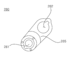
<제 2 베인링크의 구성><Configuration of the 2nd vane link>
본 실시예에서 상기 제 2 베인링크(260)는 견고한 재질로 형성되고, 직선의 형태로 길게 연장되어 형성된다. 본 실시예와 달리 상기 제 1 베인링크(250)는 곡선으로 형성될 수 있다. In this embodiment, the
상기 제 2 베인링크(260)는 제 2 베인링크바디(265)와, 상기 제 2 베인링크바디(265)에 배치되고, 상기 제 2 베인(220)과 조립되고, 상기 제 2 베인(220)과 상대 회전되는 제 2-1 베인링크축(261)과, 상기 제 2 베인링크바디(265)에 배치되고, 상기 구동링크(240, 구체적으로 제 2 구동링크축(242))와 조립되고, 상기 구동링크(240)와 상대 회전되는 제 2-2 베인링크축부(262)을 포함한다. The
본 실시예에서 상기 제 2-2 베인링크축부(262)는 제 2 베인링크바디(265)를 관통하는 홀의 형태로 형성된다. 상기 제 2-2 베인링크축부(262) 및 제 2 구동링크축(242)는 상대적인 구조이기 때문에, 하나가 축의 형태로 형성되면 나머지 하나는 회전중심을 제공하는 홀의 형태로 형성된다. 그래서 본 실시예와 달리 상기 제 2-2 베인링크축부를 축의 형태로 형성하고, 제 2 구동링크축을 홀의 형태로 형성하여도 무방하다. In this embodiment, the 2-2 vane
상기 구동링크, 제 1 베인링크, 제 2 베인링크와 결합되어 상대회전 가능한 모든 구성에서 이와 같은 구성의 치환이 가능하고, 이에 대한 변형가능한 예를 따로 상세하게 설명하진 않겠다. It is possible to replace such a configuration in all configurations that can be rotated relative to the driving link, the first vane link, and the second vane link, and a modified example thereof will not be described in detail.
<베인의 구성><Vane composition>
설명을 위해 상기 공기가 토출되는 방향을 전방으로 정의하고, 그 반대 방향을 후방으로 정의한다. 또한 천장 측을 상측으로 정의하고, 바닥을 하측으로 정의한다. For explanation, the direction in which the air is discharged is defined as forward, and the opposite direction is defined as backward. In addition, the ceiling side is defined as the upper side, and the floor is defined as the lower side.
본 실시예에서는 상기 토출구(102)에서 토출되는 공기의 유동방향을 제어하기 위해 제 1 베인(1200) 및 제 2 베인(220)이 배치된다. 상기 베인모터(230)의 각 스텝에 따라 상기 제 1 베인(1200) 및 제 2 베인(220)의 상대적인 배치 및 상대적인 각도가 변경된다. 본 실시예에서는 상기 베인모터(230)의 각 스텝에 따라 상기 제 1 베인(1200) 및 제 2 베인(220)이 쌍을 이뤄 6개의 토출스텝(P1, P2, P3, P4, P5, P6)을 제공한다. In this embodiment, the
상기 토출스텝(P1, P2, P3, P4, P5, P6)은 상기 제 1 베인(1200) 및 제 2 베인(220)이 움직이지 않고 고정된 상태로 정의한다. 이와 반대되는 개념으로 본 실시예에서는 무빙스텝을 제공할 수 있다. 무빙스텝은 6개의 토출스텝(P1, P2, P3, P4, P5, P6)들의 조합되고, 제 1 베인(1200) 및 제 2 베인(220)이 작동되면서 제공하는 기류로 정의한다. The discharge steps P1, P2, P3, P4, P5, and P6 are defined as a fixed state in which the
<제 1 베인의 구성><Configuration of the first vane>
상기 제 1 베인(1200)은 상기 제 1 모듈바디(410)의 링크설치부(404) 및 제 2 모듈바디(420)의 링크설치부(404) 사이에 배치된다. The
상기 실내기가 작동되지 않을 때, 상기 제 1 베인(1200)은 토출구(102)의 대부분을 커버한다. 본 실시예와 달리 상기 제 1 베인(1200)이 상기 토출구(102) 전체를 커버하도록 제작할 수 있다. When the indoor unit is not operated, the
상기 제 1 베인(1200)은 구동링크(240) 및 제 1 베인링크(250)와 결합된다.The
상기 구동링크(240) 및 제 1 베인링크(250)는 상기 제 1 베인(1200)의 일측 및 타측에 각각 배치된다. The driving
상기 제 1 베인(1200)은 상기 구동링크(240) 및 제 1 베인링크(250)와 각각 상대회전된다. The
구동링크(240) 및 제 1 베인링크(250)의 위치를 구분할 필요가 있을 때, 상기 제 1 모듈바디(410)에 결합된 구동링크(240)를 제 1 구동링크라 하고, 제 1 모듈바디(410)에 결합된 제 1 베인링크(250)를 제 1-1 베인링크라 정의한다. 상기 제 2 모듈바디(420)에 결합된 구동링크(240)를 제 2 구동링크라 하고, 제 2 모듈바디(420)에 결합된 제 1 베인링크(250)를 제 1-2 베인링크라 정의한다. When it is necessary to distinguish the positions of the
상기 제 1 베인(1200)은, 상기 토출구(102)의 길이방향으로 길게 연장되어 형성된 제 1 베인바디(1250)와, 상기 제 1 베인바디(1250)에서 상측으로 돌출되고, 상기 제 1 베인바디(1250)의 일측에 배치되고, 일측에 배치된 상기 구동링크(240) 및 제 1 베인링크(250)가 결합되는 제 1 조인트(1214)와, 상기 제 1 베인바디(1250)에서 상측으로 돌출되고, 상기 제 1 베인바디(1250)의 타측에 배치되고, 타측에 배치된 상기 구동링크(240) 및 제 1 베인링크(250)가 결합되는 제 2 조인트(1215)를 포함한다.The
실내기 정지상태에서, 상기 제 1 베인(1200)은 프론트바디(310) 및 흡입그릴(320) 사이에 위치되고, 토출구(102)를 커버하며, 상기 토출구(102) 내부가 사용자에게 노출되는 것을 차단한다. In the indoor unit stop state, the
그래서 상기 제 1 베인바디(1250)는 상기 프론트바디(310)의 사이드데코 이너보더(315)의 형상과 대응되는 베인아우터보더(1252)와, 상기 흡입그릴(320)의 그릴 사이드보더(325)의 형성과 대응되는 베인이너보더(1254)를 포함한다. Thus, the
토출구(102)의 공기는 베인이너보더(1254) 측에서 베인 아우터보더(1252) 측으로 토출된다. 즉, 베인아우터보더(1252)가 토출공기의 토출측에 위치된다. The air of the
본 실시예에서 제 1 조인트(1214)의 후방측 단(1214a)은 베인이너보더(1254) 보다 후방측으로 돌출되고, 제 2 조인트(1215)의 후방측 단(1215a) 역시 베인이너보더(1254)의 후방측으로 돌출된다. In this embodiment, the
그리고 상기 제 1 베인바디(1250)의 상측면에는 제 1 베인링크(250)와의 간섭을 방지하기 위한 홈(1255)(1256)이 형성된다. 상기 홈(1255)(1256)은 제 1 조인트(1214)의 바깥쪽 및 제 2 조인트(1215)의 바깥쪽에 각각 배치된다. In addition,
제 1 조인트(1214)의 바깥쪽에 형성된 홈을 제 1 홈(1255)으로 정의하고, 제 2 조인트(1215)의 바깥쪽에 형성된 홈을 제 2 홈(1255)(1256)이라 정의한다. A groove formed outside the first joint 1214 is defined as a
상기 제 1 홈(1255) 및 제 2 홈(1256)은 제 1 베인(1200)의 길이 방향으로 배치된다. 본 실시예에서 상기 제 1 홈(1255) 및 제 2 홈(1256)은 일렬로 배치된다. The
상기 제 1 홈(1255)은 제 1 조인트(1214)의 바깥쪽에 위치되고, 제 2 홈(1256)은 제 2 조인트(1215)의 바깥쪽에 위치된다. The
특히, 상기 제 1 홈(1255) 및 제 2 홈(1256)은 제 1 베인링크(250)가 결합되는 각 제 2 조인트부(1217)의 바깥쪽에 위치된다. In particular, the
상기 제 1 홈(1255) 및 제 2 홈(1256)은 일렬로 배치된다. 특히 본 실시예에서 상기 제 1 홈(1255), 제 1 조인트의 제 2 조인트부(1217), 제 2 조인트의 제 2 조인트부(1217) 및 제 2 홈(1256)은 일렬로 배치된다. The
상기 제 1 베인바디(1250)는 상기 토출유로(104)를 따라 토출되는 공기의 방향을 제어한다. 토출되는 공기는 상기 제 1 베인바디(1250)의 상측면 또는 하측면에 부딪혀 유동방향이 안내될 수 있다. 토출되는 공기의 유동방향과 상기 제 1 베인바디(1250)의 길이방향은 직교 또는 교차된다. The
상기 제 1 조인트(1214) 및 제 2 조인트(1215)는 상기 구동링크(240) 및 제 1 베인링크(250)의 결합을 위한 설치구조이다. 상기 제 1 조인트(1214)는 상기 제 1 베인(1200)의 일측에 배치되고, 제 2 조인트(1215)는 상기 제 1 베인(1200)의 타측에 배치된다. The first joint 1214 and the second joint 1215 are installation structures for coupling the
상기 제 1 조인트(1214) 및 제 2 조인트(1215)의 구성이 동일하기 때문에 제 1 조인트(1214)를 예로 들어 설명한다. Since the structures of the first joint 1214 and the second joint 1215 are the same, the first joint 1214 will be described as an example.
상기 조인트(1214)는 상기 제 1 베인바디(1250)의 상측면에서 상측으로 돌출되어 형성된다. 상기 조인트(1214)는 토출되는 공기의 유동방향을 따라 형성되고, 토출공기와의 저항을 최소화시킨다. 그래서 상기 조인트(1214)는 상기 제 1 베인바디(1250)의 길이방향에 대해 직교 또는 교차된다. The joint 1214 is formed to protrude upward from an upper surface of the
상기 조인트(1214)는 공기가 토출되는 방향 측(전방)이 낮고, 공기가 진입되는 방향 측(후방)이 높게 형성된다. 본 실시예에서 상기 조인트(1214)는 상기 구동링크(240)가 결합되는 측이 높고 제 1 베인링크(250)가 결합되는 측이 낮게 형성된다. The joint 1214 has a low side (front) in which air is discharged, and a high side (rear) in which air enters. In this embodiment, the joint 1214 is formed with a high side to which the
상기 조인트(1214)는 상기 구동링크(240)와 회전가능하게 결합되는 제 1 조인트부(1216)와, 상기 제 1 베인링크(250)와 회전가능하게 결합되는 제 2 조인트부(1217)가 형성된다. The joint 1214 is formed with a first
공기의 토출방향을 기준으로 상기 제 1 조인트부(1216)가 후방측에 위치되고, 제 2 조인트부(1217)가 전방 측에 위치된다. 본 실시예에서 상기 제 1 조인트부(1216) 및 제 2 조인트부(1217)는 홀의 형태로 형성되고, 상기 조인트(1214)를 관통한다. The first
상기 제 1 조인트부(1216) 및 제 2 조인트부(1217)는 축결합 또는 힌지결합이 가능한 구조이고, 다양한 형태로 변형가능하다. The first
상기 제 1 조인트부(1216)는 정면에서 보았을 때, 상기 제 2 조인트부(1217) 보다 높게 위치된다. 상기 제 1 조인트부(1216)에 제 1 구동링크축(241)이 조립된다. 상기 제 1 조인트부(1216)와 제 1 구동링크축(241)은 상대회전 가능하게 조립된다. 본 실시예에서는 상기 제 1 구동링크축(241)이 상기 제 1 조인트부(1216)를 관통하여 조립된다. When viewed from the front, the first
상기 제 2 조인트부(1217)는 제 1-1 베인링크축(251)이 조립된다. In the second
상기 제 2 조인트부(1217)와 제 1-1 베인링크축(251)은 상대회전 가능하게 조립된다. 본 실시예에서는 제 1-1 베인링크축(251)이 제 2 조인트부(1217)를 관통하여 조립된다. The second
탑뷰로 볼 때, 상기 구동링크(250) 및 제 1 베인링크(250)는 상기 조인트(1214) 및 링크설치부(404) 사이에 배치된다.When viewed in a top view, the driving
상기 제 2 조인트(1215)에도 제 1 조인트부(1216) 및 제 2 조인트부(1217)가 동일한 구성으로 배치된다. 제 1 조인트(1214) 및 제 2 조인트(1215)는 서로 마주보게 배치된다. The first
상기 제 1 베인(1200)은, 상기 제 1 베인바디(1200)에 배치되고, 상기 제 1 베인바디(1250)의 상측면과 소정간격 이격되는 베인루프(1220)를 더 포함한다.The
상기 베인루프(1220)는 상기 제 1 조인트(1214) 측에 배치되고, 상기 제 1 베인바디(1200)의 상측면에 연결된 제 1 루프연결부(1221)와, 상기 제 2 조인트(1215)측에 배치되고 상기 제 1 베인바디(1200)의 상측면에 연결된 제 2 루프연결부(1222)와, 상기 제 1 루프연결부(1221) 및 제 2 루프연결부(1222)를 연결하고, 상기 제 1 베인바디(1200)의 상측면과 이격되는 루프바디(1225)를 포함한다. The
상기 베인루프(1220)의 전방측 가장자리(1223) 및 후방측 가장자리(1224)는 서로 평행하다. 베인루프(1220)의 전방측 가장자리(1221)는 베인아우터보더(1252)와 대체로 평행하고, 베인루프(1220)의 후방측 가장자리(1223)는 베인이너보더(1254)와 대체로 평행하다. The
상기 베인루프(1220)는 상기 제 1 베인(1200)의 길이 방향으로 형성된다. The
탑뷰로 볼 때, 상기 베인루프(1220)는 제 1 조인트(1214) 및 제 2 조인트(1215) 사이에 배치된다. When viewed in a top view, the
베인루프(1220)는 제 1 베인바디(1250) 상측에 배치되기 때문에 사용자에게 보이지 않는다. 베인루프(1220)는 토출공기의 토출방향으로 소정의 길이를 형성하기 때문에 토출공기의 직진성을 향상시킬 수 있다.Since the
베인루프(1220)는 제 1 베인바디(1250)의 상측면과 소정의 간격을 형성한다. 본 실시예에서 상기 제 1 베인바디(1250) 및 베인루프(1220) 사이를 루프갭(1240)으로 정의한다. 보다 정확하게는 상기 제 1 베인바디(1250) 및 루프바디(1225) 사이에 상기 루프갭(1240)이 형성된다. The
상기 루프갭(1240)은 토출공기의 진행방향으로 개방된다. 즉, 상기 루프갭(1240)의 전방 측 및 후방 측이 개방되고, 토출구(102)의 토출공기는 상기 후방측으로 유입된 후 루프갭(1240)의 전방 측으로 토출된다. The
토출공기와의 저항을 최소화하기 위해 제 1 루프연결부(1221) 및 제 2 루프연결부(1222)는 완만한 곡면으로 형성된다. 제 1 루프연결부(1221) 및 제 2 루프연결부(1222)의 각 곡률중심은 상기 루프갭(1240) 안에 위치된다. To minimize resistance to discharge air, the first
상기 베인루프(1220)는 별도의 부품으로 제작될 수 있다. 본 실시예에서 베인루프(1220)는 제 1 베인바디(1250)와 일체로 제작된다. The
그리고 상기 베인루프바디(1225)는 전후 방향 폭(W)에 비해 길이가 월등하게 길게 형성된다. 그래서 베인루프바디(1225)에 처짐이 발생될 수 있고, 이를 억제하기 위해 루프서포터(1230)가 배치된다. 상기 루프서포터(1230)는 루프갭(1240)에 위치되고, 상단이 루프바디(1225)에 결합되고, 하단이 제 1 베인바디(1250)에 결합된다. In addition, the
루프서포터(1230)는 제 1 베인바디(1250) 또는 베인루프(1220)와 일체로 제작될 수 있다. 본 실시예에서 루프서포터(1230)는 제 1 베인바디(1250) 및 베인루프(1220)와 일체로 제작된다. The
상기 루프갭(1240)의 전면 및 후면이 개방되기 때문에, 상기 루프서포터(1230)를 사출한 후 금형이 용이하게 분리될 수 있다. Since the front and rear surfaces of the
상기 루프서포터(1230)는 토출공기의 토출방향으로 배치된다. 상기 루프서포터(1230)는 상하 높이는 루프갭(1240)의 높이와 동일하다. 루프서포터(1230)의 두께는 토출공기와의 저항을 최소화하기 위해 가능한 얇게 형성된다.The
본 실시예에서 상기 루프서포터(1230)의 길이방향은 베인아우터보더(1252) 또는 베인이너보더(1254)와 직교되고, 토출공기의 진행방향으로 배치된다. In this embodiment, the length direction of the
본 실시예에서 루프서포터(1230)의 길이는 상측 및 하측이 상이하다. 본 실시예에서 루프서포터(1230)의 상측 길이보다 하측 길이가 더 길게 형성된다. In this embodiment, the length of the
루프서포터(1230)의 상측은 베인루프(1220)의 전방측 가장자리(1223) 및 후방측 가장자리(1224)와 맞닿는다. 루프서포터(1230)의 상측길이는 베인루프(1220)의 폭(W)과 같다. The upper side of the
루프서포터(1230)의 하측은 상측보다 길게 형성된다. 본 실시예에서 루프서포터(1230)의 하측은 베인이너보더(1254) 측으로 연장된다. 탑뷰로 볼 때, 루프서포터(1230)의 하측단은 베인루프의 후방측 가장자리(1224) 밖으로 돌출된다. The lower side of the
본 실시예에서 루프서포터(1230)는 하측으로 갈수록 길이가 길게 형성되고, 상기 제 1 베인바디(1250)의 상측면과 접촉된 분분의 길이가 가장 길다. In this embodiment, the
상기 루프서포터(1230)는 베인루프(1220)의 길이방향으로 복수개가 배치된다. 각 루프서포터(1230)는 등간격으로 배치되는 것이 바람직하다. A plurality of
한편, 상기 제 1 베인바디(1200)는, 상기 제 1 베인바디(1250)의 상측면에 배치되고, 상기 제 1 베인바디(1250)의 길이 방향을 따라 길게 연장된 채널홈(1260)이 배치된다. Meanwhile, the
상기 채널홈(1260)은 상기 베인루프(1220)의 전방측 가장자리(1223) 및 베인아우터보더(1252) 사이에 배치된다. 본 실시예에서 채널홈(1260)은 토출공기의 진행방향으로 복수개가 배열된다. 상기 채널홈(1260)은 베인아우터보더(1252)와 평행하게 배치된다. The
상기 채널홈(1260)은 제 1 베인바디(1250)의 상측면에서 하측으로 오목하게 형성된다. The
상기 채널홈(1260)은 제 1 베인바디(1250)의 베인아우터보더(1252)와 가깝게 배치되고, 토출공기는 상기 채널홈(1260)과의 간섭을 통해 직진성이 향상된다. 상기 토출공기의 토출방향과 상기 채널홈(1260)의 길이방향이 직교될 수 있다. The
<제 2 베인의 구성><Configuration of the second vane>
상기 제 2 베인(220)은 상기 토출구(102)의 길이방향으로 길게 연장되어 형성된 제 2 베인바디(222)와, 상기 제 2 베인바디(222)에서 상측으로 돌출되고, 상기 제 2 베인링크(260)와 상대회전 가능하게 결합되는 조인트(224)와, 상기 제 2 베인바디(222)에 형성되고, 상기 링크설치부(404)와 회전 가능하게 결합되는 제 2 베인축(221)을 포함한다. The
상기 조인트(224)는 축결합 또는 힌지결합이 가능한 구조이고, 다양한 형태로 변형가능하다. The joint 224 is a structure capable of axial coupling or hinge coupling, and can be modified in various forms.
제 1 베인의 조인트(1214)와 제 2 베인의 제 2 조인트(224)를 구분할 필요가 있을 때, 제 1 베인의 조인트를 제 1 조인트(1214)라 정의하고, 상기 제 2 베인의 조인트를 제 2 조인트(224)라 정의한다. When it is necessary to distinguish the first vane joint 1214 from the second vane second joint 224, the first vane joint is defined as the first joint 1214, and the second vane joint is removed. It is defined as 2 joint 224.
상기 제 2 베인(220)은 제 2 조인트(224)을 중심으로 상대회전될 수 있고, 상기 제 2 베인축(221)을 중심으로도 상대회전될 수 있다. 즉, 상기 제 2 베인(220)은 제 2 조인트(224) 및 제 2 베인축(221) 각각에서 상대회전이 이루어질 수 있다. The
탑뷰로 볼 때, 상기 제 2 조인트(224)는 상기 제 2 베인축(221) 보다 전방에 위치된다. 상기 제 2 조인트(224)는 상기 제 2 베인축(221)을 중심으로 일정한 궤도로 움직인다.When viewed in a top view, the second joint 224 is positioned in front of the
상기 제 2 베인바디(222)는 완만한 곡면으로 형성될 수 있다.The second vane body 222 may be formed with a gentle curved surface.
상기 제 2 베인바디(222)는 상기 토출유로(104)를 따라 토출되는 공기의 방향을 제어한다. 토출되는 공기는 상기 제 2 베인바디(222)의 상측면 또는 하측면에 부딪혀 유동방향이 안내된다. The second vane body 222 controls the direction of air discharged along the
토출되는 공기의 유동방향과 상기 제 2 베인바디(222)의 길이방향은 직교 또는 교차된다. The flow direction of the discharged air and the longitudinal direction of the second vane body 222 are orthogonal or intersecting.
탑뷰로 볼 때, 상기 제 2 베인바디(222)의 적어도 일부는 상기 제 1 베인(1200)의 제 1 조인트부(1216)들 사이에 위치될 수 있다. When viewed in a top view, at least a portion of the second vane body 222 may be located between the first
이는 상기 제 2 베인(220)이 제 1 베인(1200)의 상측에 위치될 때, 간섭을 방지하기 위한 구조이다. 상기 제 2 베인바디(222)의 전방 측 단은 상기 제 1 조인트부(1214) 사이에 위치된다. 즉 상기 제 2 베인바디(222)의 전방측 길이는 상기 제 1 조인트부(1214) 사이의 길이보다 작게 형성된다. This is a structure for preventing interference when the
상기 제 2 조인트(224)는 제 2 베인링크(260)와의 조립을 위한 설치구조이다. 상기 제 2 조인트(224)는 상기 제 2 베인바디(222)의 일측 및 타측에 각각 배치된다. The second joint 224 is an installation structure for assembling with the
상기 제 2 조인트(224)에는 상기 제 2 베인링크(260)와 상대회전 가능하게 결합된다. The second joint 224 is coupled to the
상기 제 2 조인트(224)는 상기 제 2 베인바디(222)의 상측면에서 상측으로 돌출되어 형성된다. 상기 제 2 조인트(224)는 토출되는 공기의 유동방향을 따라 형성되는 것이 바람직하다. 그래서 상기 제 2 조인트(224)는 상기 제 2 베인바디(222)의 길이방향에 대해 직교 또는 교차되게 배치된다. The second joint 224 is formed to protrude upward from an upper surface of the second vane body 222. The second joint 224 is preferably formed along the flow direction of the discharged air. So, the second joint 224 is disposed to be orthogonal or crossed with respect to the longitudinal direction of the second vane body 222.
그리고 상기 제 2 베인(220)은 상기 제 2 베인축(221)을 중심으로 회전된다. 상기 제 2 베인축(221)은 상기 제 2 베인바디(222)의 일측 및 타측에 각각 형성된다.And the
상기 일측의 제 2 베인축(221)은 일측에 배치된 링크설치부(404)를 향해 돌출되고, 상기 타측의 제 2 베인축(221)은 타측에 배치된 링크설치부(404)를 향해 돌출된다. The
상기 모듈바디(400)에는 상기 제 2 베인축(221)과 회전가능하게 결합되는 제 2 베인결합부(411)가 배치된다. 본 실시예에서 상기 제 2 베인결합부(411)는 상기 모듈바디(400)를 관통하는 홀 형태로 형성된다. A second
상기 제 2 베인축(221)은 상기 제 2 조인트(224) 보다 후방 측에 위치된다. 상기 제 2 베인축(221) 전방으로 제 2 베인링크(260), 구동링크(240), 제 1 베인링크(250)가 순서대로 배치된다. The
그리고 상기 제 2 베인결합부(411) 전방으로 구동링크결합부(407), 제 1 베인링크결합부(408)가 순서대로 배치된다. In addition, the driving
<베인모듈 및 흡입그릴의 배치><Arrangement of vane module and suction grill>
도 1 내지 4 및, 도 15 내지 17을 참조하여 베인모듈의 결합구조 및 분리구조에 대해 보다 상세하게 설명한다. The coupling structure and separation structure of the vane module will be described in more detail with reference to FIGS. 1 to 4 and FIGS. 15 to 17.
도 1의 상태에서 흡입그릴(320)을 분리하면, 도 15에 도시된 것과 같이 4개의 베인모듈(200)이 노출된다. 상기 흡입그릴(320)은 프론트바디(310)에 분리가능하게 조립된다. When the
상기 흡입그릴(320)은 다양한 방법으로 프론트바디(310)에서 분리될 수 있다.The
상기 흡입그릴(320)는 한쪽 가장자리를 기준으로 반대쪽이 분리되어 회전되는 방식으로 분리될 수 있다. 다른 방식으로 상기 흡입그릴(320)은 프론트바디(310)에 상호걸림된 상태에서 걸림이 해제되어 분리될 수 있다. 다른 방식으로 상기 흡입그릴(200)은 자기력에 의해 프론트바디(310)에 결합된 상태를 유지할 수 있다. The
본 실시예에서 상기 흡입그릴(320)는 프론트바디(310)에 설치된 엘리베이터(500)에 의해 상하 방향으로 이동될 수 있다. 상기 엘리베이터(500)는 상기 흡입그릴(320)과 와이어(미도시)를 통해 연결된다. 상기 엘리베이터(500)의 작동에 의해 상기 와이어가 풀리거나 감기고, 이를 통해 상기 흡입그릴(320)를 하측으로 이동시키거나 상측으로 이동시킬 수 있다. In this embodiment, the
상기 엘리베이터(500)는 복수개 배치되고, 각 엘리베이터(500)는 상기 흡입그릴(320)의 양측을 동시에 이동시킨다. A plurality of
상기 흡입그릴(320)이 하측으로 이동되면, 상기 흡입그릴(320)의해 가려져 있던 제 1 모듈바디(410) 및 제 2 모듈바디(420)가 노출된다.When the
상기 흡입그릴(320)이 프론트바디(310)에 조립된 상태에서, 상기 베인모듈(200)의 제 1 베인(1200) 및 제 2 베인(220) 중 적어도 어느 하나가 노출될 수 있다. In the state where the
실내기가 작동하지 않을 때는, 상기 제 1 베인(1200)만 사용자에게 노출된다. 실내기가 작동되어 토출공기가 배출될 때는 상기 제 2 베인(220)이 선택적으로 사용자에게 노출될 수 있다. When the indoor unit does not work, only the
상기 흡입그릴(320)이 프론트바디(310)에 조립된 상태에서, 상기 베인모듈(200) 중 상기 제 1 모듈바디(410) 및 제 2 모듈바디(420)는 상기 흡입그릴(320)에 가려진다. In the state in which the
상기 제 1 모듈바디(410) 및 제 2 모듈바디(420)에 각각 체결홀(403)이 배치되기 때문에, 상기 각 체결홀(403)은 상기 흡입그릴(320)에 가려져 사용자에게 은닉된다. Since the fastening holes 403 are disposed in the
그리고 상기 흡입그릴(320)을 구성하는 상기 그릴코너부(327) 상측에 상기 제 1 모듈바디(410) 및 제 2 모듈바디(420)가 위치되기 때문에, 상기 그릴코너부(327)는 상기 제 1 모듈바디(410) 및 제 2 모듈바디(420)이 외부로 노출되는 것을 차단한다. In addition, since the
상기 그릴코너부(327)는 상기 제 1 모듈바디(410) 및 제 2 모듈바디(420)에 형성된 체결홀(403)들이 노출되는 것도 차단한다. 상기 그릴코너부(327)는 상기 체결홀(403)의 하측에 위치되기 때문에 상기 체결홀(403)은 상기 그릴코너부(327)에 의해 은닉된다.The grill corner portion 327 also blocks the fastening holes 403 formed in the
이를 보다 구체적으로 설명하면, 상기 흡입그릴(320)은, 상기 흡입구(101)의 하측에 배치되고, 다수개의 그릴홀(321)에 의해 상기 흡입구(101)와 연통되고, 사각형 형상으로 형성된 그릴바디(322)와, 상기 그릴바디(322)의 각 모서리에서 대각선방향으로 연장되어 형성된 제 1 그릴코너부(327-1), 제 2 그릴코너부(327-2), 제 3 그릴코너부(327-3), 제 4 그릴코너부(327-4)를 포함한다. In more detail, the
상기 베인모듈(200)은, 상기 흡입그릴(320)의 각 가장자리 외측에 배치되고, 상기 제 1 그릴코너부(327-1) 및 제 2 그릴코너부(327-2) 사이에 배치된 제 1 베인모듈(201)과, 상기 흡입그릴(320)의 각 가장자리 외측에 배치되고, 상기 제 2 그릴코너부(327-2) 및 제 3 그릴코너부(327-3) 사이에 배치된 제 2 베인모듈(202)과, 상기 흡입그릴(320)의 각 가장자리 외측에 위치되고, 상기 제 3 그릴코너부(327-3) 및 제 4 그릴코너부(327-4) 사이에 배치된 제 3 베인모듈(203) 및 상기 흡입그릴(320)의 각 가장자리 외측에 배치되고, 상기 제 4 그릴코너부(327-4) 및 제 1 그릴코너부(327-1) 사이에 배치된 제 4 베인모듈(204)을 포함한다. The
상기 제 1 베인모듈(201) 및 제 2 베인모듈(202) 사이에 배치된 제 1 모듈바디(410) 및 제 2 모듈바디(420)는 상기 제 1 그릴코너부(327-1) 상측에 위치되고, 상기 제 1 그릴코너부(327-1)에 의해 숨겨진다. 구체적으로 상기 제 1 그릴코너부의 상측에 상기 제 1 베인모듈의 제 2 모듈바디 및 제 2 베인모듈의 제 1 모듈바디가 배치된다. The
상기 제 2 베인모듈(202) 및 제 3 베인모듈(203) 사이에 배치된 제 1 모듈바디 및 제 2 모듈바디는 상기 제 2 그릴코너부(327-2) 상측에 위치되고, 상기 제 2 그릴코너부(327-2)에 의해 숨겨진다. 구체적으로 상기 제 2 그릴코너부의 상측에 상기 제 2 베인모듈의 제 2 모듈바디 및 제 3 베인모듈의 제 1 모듈바디가 배치된다. The first module body and the second module body disposed between the second vane module 202 and the third vane module 203 are positioned above the second grill corner portion 327-2, and the second grille. It is hidden by the corner portion 327-2. Specifically, the second module body of the second vane module and the first module body of the third vane module are disposed above the second grill corner portion.
상기 제 3 베인모듈(203) 및 제 4 베인모듈(204) 사이에 배치된 제 1 모듈바디 및 제 2 모듈바디는 상기 제 3 그릴코너부(327-3) 상측에 위치되고, 상기 제 3 그릴코너부(327-3)에 의해 숨겨진다. 구체적으로 상기 제 3 그릴코너부의 상측에 상기 제 3 베인모듈의 제 2 모듈바디 및 제 4 베인모듈의 제 1 모듈바디가 배치된다. The first module body and the second module body disposed between the third vane module 203 and the fourth vane module 204 are located above the third grill corner portion 327-3, and the third grille. It is hidden by the corner portion 327-3. Specifically, the second module body of the third vane module and the first module body of the fourth vane module are disposed above the third grill corner portion.
상기 제 4 베인모듈(204) 및 제 1 베인모듈(201) 사이에 배치된 제 1 모듈바디 및 제 2 모듈바디는 상기 제 4 그릴코너부(327-4) 상측에 위치되고, 상기 제 4 그릴코너부(327-1)에 의해 숨겨진다. 구체적으로 상기 제 4 그릴코너부의 상측에 상기 제 4 베인모듈의 제 2 모듈바디 및 제 1 베인모듈의 제 1 모듈바디가 배치된다. The first module body and the second module body disposed between the fourth vane module 204 and the first vane module 201 are located above the fourth grill corner portion 327-4, and the fourth grill It is hidden by the corner portion 327-1. Specifically, the second module body of the fourth vane module and the first module body of the first vane module are disposed above the fourth grill corner portion.
도 15를 참조하면, 12시 방향에 배치된 베인모듈(200)을 제 1 베인모듈(201)로 정의하고, 3시 방향에 배치된 베인모듈(200)을 제 2 베인모듈(202)로 정의하고, 6시 방향에 배치된 베인모듈(200)을 제 3 베인모듈(203)로 정의하고, 9시 방향에 배치된 베인모듈(200)을 제 4 베인모듈(204)로 정의한다. 15, the
상기 제 1 베인모듈(201), 제 2 베인모듈(202), 제 3 베인모듈(203) 및 제 4 베인모듈(204)은 프론트패널(300)의 중심(C)을 기준으로 90도 간격으로 배치된다. The first vane module 201, the second vane module 202, the third vane module 203, and the fourth vane module 204 are spaced at 90 degree intervals based on the center C of the
상기 제 1 베인모듈(201) 및 제 3 베인모듈(203)은 평행하게 배치되고, 상기 제 2 베인모듈(202) 및 제 4 베인모듈(204)은 평행하게 배치된다. The first vane module 201 and the third vane module 203 are arranged in parallel, and the second vane module 202 and the fourth vane module 204 are arranged in parallel.
상기 프론트바디(310)에는 4개의 사이드커버(314)가 배치된다. 설명의 편의를 위해, 상기 제 1 베인모듈(201) 외측에 배치된 사이드커버(314)를 제 1 사이드커버(314-1)로 정의하고, 상기 제 2 베인모듈(202) 외측에 배치된 사이드커버(314)를 제 2 사이드커버(314-2)로 정의하고, 상기 제 3 베인모듈(203) 외측에 배치된 사이드커버(314)를 제 3 사이드커버(314-3)로 정의하고, 상기 제 4 베인모듈(204) 외측에 배치된 사이드커버(314)를 제 4 사이드커버(314-4)로 정의한다. Four side covers 314 are disposed on the
각 사이드커버(314)는 상기 프론트프레임(312)의 가장자리에 조립되고, 상기 프론트프레임(312)의 하측에 위치되고, 외부에 노출되고, 각 베인모듈(202) 외측에 배치된다. Each
그리고 제 1 베인모듈(201) 및 제 2 베인모듈(202) 사이에 배치된 코너커버(316)를 제 1 코너커버(316-1)로 정의한다. 제 2 베인모듈(202) 및 제 3 베인모듈(203) 사이에 배치된 코너커버(316)를 제 2 코너커버(316-2)로 정의한다. 제 3 베인모듈(203) 및 제 4 베인모듈(204) 사이에 배치된 코너커버(316)를 제 3 코너커버(316-3)로 정의한다. 제 4 베인모듈(204) 및 제 1 베인모듈(201) 사이에 배치된 코너커버(316)를 제 4 코너커버(316-4)로 정의한다. In addition, the
상기 제 1 코너커버(316-1)는 상기 프론트프레임(312)의 모서리에 조립되고, 상기 프론트프레임(312)의 하측에 위치되고, 상기 제 1 사이드커버(314-1) 및 제 2 사이드커버(314-2) 사이에 위치되고, 외부에 노출된다. The first corner cover 316-1 is assembled to the corner of the
상기 제 2 코너커버(316-2)는 상기 프론트프레임(312)의 모서리에 조립되고, 상기 프론트프레임(312)의 하측에 위치되고, 상기 제 2 사이드커버(314-2) 및 제 3 사이드커버(314-3) 사이에 위치되고, 외부에 노출된다. The second corner cover 316-2 is assembled to the corner of the
상기 제 3 코너커버(316-3)는 상기 프론트프레임(312)의 모서리에 조립되고, 상기 프론트프레임(312)의 하측에 위치되고, 상기 제 3 사이드커버(314-1) 및 제 4 사이드커버(314-4) 사이에 위치되고, 외부에 노출된다. The third corner cover 316-3 is assembled to the corner of the
상기 제 4 코너커버(316-4)는 상기 프론트프레임(312)의 모서리에 조립되고, 상기 프론트프레임(312)의 하측에 위치되고, 상기 제 4 사이드커버(314-1) 및 제 1 사이드커버(314-1) 사이에 위치되고, 외부에 노출된다. The fourth corner cover 316-4 is assembled to the corner of the
제 1 코너커버(316-1) 및 제 3 코너커버(316-3)는 프론트패널(300)의 중심(C)을 기준으로 대각선 방향으로 배치되고, 서로 마주보게 배치된다. 제 2 코너커버(316-2) 및 제 4 코너커버(316-4)는 프론트패널(300)의 중심(C)을 기준으로 대각선 방향으로 배치되고, 서로 마주보게 배치된다. The first corner cover 316-1 and the third corner cover 316-3 are arranged diagonally relative to the center C of the
상기 프론트패널(300)의 중심을 지나는 가상의 대각선을 P1 및 P2로 정의한다. 상기 P1은 제 1 코너커버(316-1) 및 제 3 코너커버(316-3)를 연결하는 가상의 선이고, 상기 P2는 제 2 코너커버(316-2) 및 제 4 코너커버(316-4)를 연결하는 가상의 선이다.The virtual diagonal line passing through the center of the
상기 흡입패널(320)에는 모서리 측으로 연장되어 형성된 제 1 그릴코너부(327-1), 제 2 그릴코너부(327-2), 제 3 그릴코너부(327-3) 및 제 4 그릴코너부(327-4)가 배치된다. The
상기 그릴코너부들을 기준으로 상기 제 1 베인모듈(201)은 상기 흡입그릴(320)의 각 가장자리 외측에 배치되고, 상기 제 1 그릴코너부(327-1) 및 제 2 그릴코너부(327-2) 사이에 배치된다. Based on the grill corner portions, the first vane module 201 is disposed outside each edge of the
상기 제 2 베인모듈(202)은 상기 흡입그릴의 각 가장자리 외측에 배치되고, 상기 제 2 그릴코너부(327-2) 및 제 3 그릴코너부(327-3) 사이에 배치된다. The second vane module 202 is disposed outside each edge of the suction grill, and is disposed between the second grill corner portion 327-2 and the third grill corner portion 327-3.
상기 제 3 베인모듈(203)은 상기 흡입그릴의 각 가장자리 외측에 배치되고, 상기 제 3 그릴코너부(327-3) 및 제 4 그릴코너부(327-4) 사이에 배치된다. The third vane module 203 is disposed outside each edge of the suction grill, and is disposed between the third grill corner portion 327-3 and the fourth grill corner portion 327-4.
상기 제 4 베인모듈(204)은 및 상기 흡입그릴의 각 가장자리 외측에 배치되고, 상기 제 4 그릴코너부(327-4) 및 제 1 그릴코너부(327-1) 사이에 배치된다. The fourth vane module 204 is disposed outside each edge of the suction grill, and is disposed between the fourth grill corner portion 327-4 and the first grill corner portion 327-1.
상기 제 1 그릴코너부(327-1)는 상기 제 1 코너커버(316-1)를 향해 연장되어 형성되고, 상기 제 1 코너커버(316-1)의 외측면과 연속된 면을 형성한다.The first grill corner portion 327-1 is formed to extend toward the first corner cover 316-1, and forms a continuous surface with the outer surface of the first corner cover 316-1.
상기 제 1 그릴코너부(327-1)의 그릴 코너보더(326)는 상기 제 1 코너커버(316-1)의 코너데코 이너보더(317)와 대향되고, 코너데코 이너보더 갭(317a)을 형성한다. The
나머지 그릴코너부(327)의 그릴 코너보더(326)와 상기 코너커버(316)의 코너데코 이너보더(317)도 각각 대향되고, 각각 코너데코 이너보더 갭(317a)을 형성한다. The grille corner borders 326 of the remaining grill corner portions 327 and the corner deco
상기 제 1 모듈바디(410) 및 제 2 모듈바디(420)는 코너커버(316) 내측(구체적으로 프론트패널의 중심(C) 측)에 위치된다. 특히 상기 가상의 대각선(P1, P2)을 기준으로 상기 제 1 모듈바디(410) 및 제 2 모듈바디(420)가 서로 마주보게 배치된다.The
구체적으로 상기 제 1 베인모듈(201)의 제 1 모듈바디(410)와 상기 제 4 베인모듈(204)의 제 2 모듈바디(420)는 가상의 대각선(P2)를 기준으로 서로 마주보게 배치된다. Specifically, the
그리고 상기 제 2 베인모듈(202)의 제 1 모듈바디(410)와 상기 제 1 베인모듈(201)의 제 2 모듈바디(420)는 가상의 대각선(P1)를 기준으로 서로 마주보게 배치된다. In addition, the
그리고 상기 제 3 베인모듈(201)의 제 1 모듈바디(410)와 상기 제 2 베인모듈(202)의 제 2 모듈바디(420)는 가상의 대각선(P2)를 기준으로 서로 마주보게 배치된다. In addition, the
그리고 상기 제 4 베인모듈(204)의 제 1 모듈바디(410)와 상기 제 3 베인모듈(203)의 제 2 모듈바디(420)는 가상의 대각선(P1)를 기준으로 서로 마주보게 배치된다. In addition, the
한편, 상기 흡입그릴(320)은 상기 제 1 모듈바디(410)들 및 제 2 모듈바디(420)들의 하측에 위치되고, 상기 제 1 모듈바디(410)들 및 제 2 모듈바디(420)들이 노출되지 않도록 은닉한다. 즉, 상기 흡입그릴(320)이 프론트바디(310)에 밀착된 경우, 상기 제 1 모듈바디(410)들 및 제 2 모듈바디(420)들은 흡입그릴(320)에 가려져 사용자에게 노출되지 않는다. Meanwhile, the
상기 제 1 모듈바디(410)들 및 제 2 모듈바디(420)들이 숨겨지기 때문에, 상기 제 1 모듈바디(410)들 및 제 2 모듈바디(420)들은 흡입그릴(320)에 형성된 체결홀(403)들도 사용자에게 숨겨지는 장점이 있다. Since the
상기 흡입그릴(320)은 각 코너커버(316)들과 마주하게 배치되는 4개의 그릴코너부(327)가 형성된다. 상기 각 그릴코너부(327)는 상기 각 코너커버(316)와 대향되게 배치된다. The
상기 제 1 코너커버(316-1)와 대향되게 배치된 그릴코너부(327)를 제 1 그릴코너부(327-1)로 정의하고, 상기 제 2 코너커버(316-2)와 대향되게 배치된 그릴코너부(327)를 제 1 그릴코너부(327-2)로 정의하고, 상기 제 3 코너커버(316-3)와 대향되게 배치된 그릴코너부(327)를 제 3 그릴코너부(327-3)로 정의하고, 상기 제 4 코너커버(316-4)와 대향되게 배치된 그릴코너부(327)를 제 4 그릴코너부(327-4)로 정의한다. A grill corner portion 327 disposed to face the first corner cover 316-1 is defined as a first grill corner portion 327-1, and is disposed to face the second corner cover 316-2. The defined grill corner portion 327 is defined as the first grill corner portion 327-2, and the grill corner portion 327 disposed opposite to the third corner cover 316-3 is the third grill corner portion ( 327-3), and the grill corner portion 327 disposed opposite to the fourth corner cover 316-4 is defined as a fourth grill corner portion 327-4.
바텀뷰로 볼 때, 복수개의 모듈바디(400)들은 그릴코너부(327)의 상측에 위치되고, 상기 그릴코너부(327)에 의해 숨겨진다. In a bottom view, a plurality of module bodies 400 are positioned above the grill corner portion 327 and hidden by the grill corner portion 327.
특히, 상기 그릴코너부(327)의 가장자리를 형성하는 그릴 사이드보더(325)는 코너커버(316)의 안쪽 가장자리를 형성하는 코너데코 이너보더(317)와 마주보게 배치되고, 곡선의 형태도 서로 대응된다. In particular, the
마찬가지로 상기 그릴코너부(327)의 가장자리를 형성하는 그릴 코너보더(326)는 제 1 베인(1200)의 내측 가장자리와 마주보게 배치되고, 곡선의 형태도 서로 대응된다. Likewise, the
한편, 본 실시예에서는 상기 흡입그릴(320)이 상기 프론트바디(310)에 밀착된 상태를 유지시키기 위해, 영구자석(318) 및 자기력고정부(328)가 배치된다.On the other hand, in this embodiment, in order to maintain the state in which the
상기 프론트바디(310)에 영구자석(318) 또는 자기력고정부(328) 중 어느 하나가 배치될 수 있고, 상기 각 그릴코너부(327) 상측면에 상기 자기력고정부(328) 또는 영구자석(318) 중 다른 하나가 배치될 수 있다. Either a
상기 영구자석(318) 및 자기력고정부(328)는 각 그릴코너부(327) 상측에 위치되고, 상기 각 그릴코너부(327)에 의해 숨겨진다. 상기 영구자석(318) 및 자기력고정부(328)가 흡입그릴(320)의 각 모서리 바깥쪽에 위치되기 때문에 흡입그릴(320)과 프론트바디(310)의 이격을 최소화시킬 수 있다.The
상기 흡입그릴(320) 및 프론트바디(310)가 이격될 경우, 상기 흡입유로(103) 내부 압력이 저하되는 문제가 발생된다. When the
본 실시예에서 상기 영구자석(318)은 상기 프론트바디(310)에 배치된다. 구체적으로 상기 영구자석은 코너프레임(313)에 배치된다. In this embodiment, the
상기 자기력고정부(328)는 상기 영구자석(318)와 상호작용되어 인력을 형성하는 금속재질로 형성된다. 상기 자기력고정부(328)는 상기 흡입그릴(320)의 상측면에 배치된다. 구체적으로 상기 자기력고정부(328)는 그릴코너부(327) 상측면에 배치된다. The magnetic
상기 흡입그릴(320)이 상측으로 이동되고, 상기 영구자석(318)에 근접될 경우, 상기 영구자석(318)이 상기 자기력고정부(328)을 끌어당겨 상기 흡입그릴(320)를 고정한다. 상기 영구자석(318)의 자기력은 상기 흡입그릴(320)의 자중 보다 작게 형성된다. 그래서 상기 엘리베이터(500)에 의해 흡입그릴(320)이 당겨지지 않을 경우, 상기 영구자석(318) 및 자기력고정부(328)의 결합은 해제된다. When the
탑뷰 또는 바텀뷰로 볼 때, 상기 영구자석(318)은 상기 가상의 대각선 P1 및 P2 선상에 배치된다. 상기 영구자석(318)은 코너커버(316) 내측에 위치된다. When viewed in a top view or bottom view, the
탑뷰 또는 바텀뷰로 볼 때, 4개의 영구자석(318) 중 하나는 제 1 베인모듈(201)의 제 1 모듈바디(410) 및 제 4 베인모듈(204)의 제 2 모듈바디(420) 사이에 배치된다. 나머지 3개의 영구자석도 각 베인모듈들의 제 1 모듈바디(410) 및 제 2 모듈바디(420) 사이에 배치된다. When viewed in a top view or bottom view, one of the four
상기 영구자석(318) 및 자기력고정부(328)는 각 그릴코너부(327) 상측에 위치되고, 상기 각 그릴코너부(327)에 의해 숨겨진다. The
<베인모듈의 분리과정 및 조립과정><Separation and assembly process of vane module>
4개의 베인모듈 중 적어도 어느 하나의 베인모듈(200)에 대해 서비스가 필요한 경우, 작업자는 먼저 흡입그릴(320)를 하측으로 이동시켜야 한다. When service is required for at least one
상기 흡입그릴(320)이 하측으로 이동되면, 상기 흡입그릴(320)에 가려져 있던 모든 모듈바디(400)들이 노출된다.When the
이후 작업자는 서비스가 필요한 베인모듈(200)의 체결홀(403)에서 체결부재(401)를 분리한다. 여기서 상기 모듈바디(400)는 모듈후크(405)에 의해 프론트바디(410)에 결합된 상태이기 때문에, 상기 체결부재(401)(403)가 분리되어도 베인모듈(200)이 낙하하지 않는다. 상기 베인모듈(200)의 결합이 체결부재(401)에 전적으로 의존하지 않기 때문에, 체결부재(401)를 분리하여도 베인모듈(200) 낙하에 따른 안전사고의 위험이 없다. Thereafter, the operator separates the fastening member 401 from the
체결부재(401) 분리 후에, 작업자는 분리대상 모듈바디(400)의 모듈후크(405)의 상호걸림을 해제함으로써, 상기 프론트바디(310)에서 베인모듈(200) 전체를 분리할 수 있다. 이후 작업자는 분리된 베인모듈(200)에서 베인모터(230)와 연결된 케이블(미도시)을 분리하고, 하나의 베인모듈(200) 전체를 프론트바디(310)에서 분리할 수 있다. After the fastening member 401 is removed, the operator can separate the
상기 베인모듈(200)은 프론트바디(310)의 하측으로 분리되기 때문에, 프론트바디(310)를 분리하지 않고도 서비스가 필요한 베인모듈(200)만을 분리할 수 있다.Since the
더불어 상기 베인모듈(200)은 체결부재(401), 모듈후크(405) 외에 케이블과도 결합된 상태이기 때문에, 체결부재(401) 및 모듈후크(405)가 해제되어도 바닥으로 직접 낙하하진 않는다. 즉, 작업자가 체결부재(401), 모듈후크(405)를 해체한 후, 실수로 베인모듈(200)을 떨어뜨릴 찌라도, 상기 베인모듈(200)은 상기 케이블에 매달린 상태를 유지한다. In addition, since the
상기 베인모듈(200)의 분리 후, 장착과정은 역순으로 진행한다.After the
상기 케이블과 베인모터(230)를 연결한 후, 모듈후크(405)를 통해 프론트바디(310)에 조립하고, 체결부재(401)를 통해 제 1 모듈바디(410) 및 제 2 모듈바디(420)를 프론트바디(310)에 각각 조립한다. 이후 상기 흡입그릴(320)를 원위치로 상승시켜 서비스를 완료한다. After connecting the cable and the
이상 첨부된 도면을 참조하여 본 발명의 실시예들을 설명하였으나, 본 발명은 상기 실시예들에 한정되는 것이 아니라 서로 다른 다양한 형태로 제조될 수 있으며, 본 발명이 속하는 기술분야에서 통상의 지식을 가진 자는 본 발명의 기술적 사상이나 필수적인 특징을 변경하지 않고서 다른 구체적인 형태로 실시될 수 있다는 것을 이해할 수 있을 것이다. 그러므로 이상에서 기술한 실시예들은 모든 면에서 예시적인 것이며 한정적이 아닌 것으로 이해해야만 한다.The embodiments of the present invention have been described above with reference to the accompanying drawings, but the present invention is not limited to the above embodiments, and may be manufactured in various different forms, and having ordinary knowledge in the technical field to which the present invention pertains. It will be understood that a person can be implemented in other specific forms without changing the technical spirit or essential features of the present invention. Therefore, it should be understood that the embodiments described above are illustrative in all respects and not restrictive.
100 : 케이스
101 : 흡입구
102 : 토출구
103 : 흡입유로
104 : 토출유로
110 : 케이스하우징
120 : 프론트패널
130 : 실내열교환기
140 : 실내송풍팬
200 : 베인모듈
230 : 베인모터
240 : 구동링크
250 : 제 1 베인링크
260: 제 2 베인링크
300 : 프론트패널
310 : 프론트바디
320 : 흡입그릴
330 : 프리필터
400 : 모듈바디
410 : 제 1 모듈바디
420 : 제 2 모듈바디
500 : 엘리베이터
1200 : 제 1 베인
1210 : 베인루프
1230 : 루프서포터
1240 : 루프갭
1250 : 제 1 베인바디100: case 101: inlet
102: outlet 103: suction passage
104: discharge flow path 110: case housing
120: front panel 130: indoor heat exchanger
140: indoor blowing fan 200: vane module
230: vane motor 240: drive link
250: first vane link 260: second vane link
300: Front panel 310: Front body
320: suction grill 330: pre-filter
400: module body 410: first module body
420: Second module body 500: Elevator
1200: first vane 1210: vane loop
1230: loop supporter 1240: loop gap
1250: 1st vane body
Claims (10)
상기 케이스하우징의 저면을 커버하고, 하측을 향해 흡입구 및 토출구가 형성된 프론트바디;
상기 프론트바디에 배치되고, 상기 토출구에서 토출되는 공기의 유동방향을 조절하는 베인모듈;을 포함하고,
상기 베인모듈은,
상기 토출구의 일측에 배치되고, 상기 프론트바디에 조립된 제 1 모듈바디;
상기 토출구의 타측에 배치되고, 상기 프론트바디에 조립된 제 2 모듈바디;
일측 및 타측이 상기 제 1 모듈바디 및 제 2 모듈바디와 각각 결합되고, 상기 제 1 모듈바디 및 제 2 모듈바디에 대해 상대회전되는 제 1 베인;
상기 제 1 모듈바디 또는 제 2 모듈바디 중 적어도 어느 하나에 설치되고, 상기 제 1 베인에 구동력을 제공하는 베인모터;를 포함하고,
상기 제 1 베인은,
상기 토출구의 길이방향으로 길게 연장되어 형성된 제 1 베인바디;
상기 제 1 베인바디에 배치되고, 상기 제 1 베인바디의 상측면과 소정간격 이격되어 루프갭을 형성시키는 베인루프;를 포함하는 천장형 공기조화기의 실내기.It is installed hanging from the ceiling of the interior, the case housing formed by opening the bottom surface;
A front body covering the bottom surface of the case housing and having a suction port and a discharge port toward a lower side;
Included in the vane module disposed on the front body, to adjust the flow direction of the air discharged from the discharge port;
The vane module,
A first module body disposed on one side of the discharge port and assembled to the front body;
A second module body disposed on the other side of the discharge port and assembled to the front body;
A first vane of which one side and the other side are respectively coupled to the first module body and the second module body, and are rotated relative to the first module body and the second module body;
Includes a vane motor that is installed on at least one of the first module body or the second module body, and provides a driving force to the first vane.
The first vane,
A first vane body extended and formed in the longitudinal direction of the discharge port;
An indoor unit of a ceiling-type air conditioner including; a vane loop disposed on the first vane body and spaced apart from the upper surface of the first vane body to form a loop gap.
상기 베인루프는,
상기 제 1 모듈바디 측에 배치되고, 상기 제 1 베인바디의 상측면에 연결된 제 1 루프연결부;
상기 제 2 모듈바디 측에 배치되고 상기 제 1 베인바디의 상측면에 연결된 제 2 루프연결부;
상기 제 1 루프연결부 및 제 2 루프연결부를 연결하고, 상기 제 1 베인바디와 상기 루프갭을 형성하는 루프바디;를 포함하는 천장형 공기조화기의 실내기.The method according to claim 1,
The vane loop,
A first loop connection part disposed on the first module body and connected to an upper side of the first vane body;
A second loop connection part disposed on the second module body and connected to an upper side of the first vane body;
And a roof body connecting the first loop connection portion and the second loop connection portion and forming the first vane body and the loop gap.
상기 루프갭에 배치되고, 상기 루프바디 및 제 1 베인바디를 연결하는 루프서포터;를 더 포함하는 천장형 공기조화기의 실내기.The method according to claim 2,
An indoor unit of the ceiling air conditioner further comprising a roof supporter disposed in the roof gap and connecting the roof body and the first vane body.
상기 루프서포터는 상기 루프바디의 길이방향을 따라 복수개가 배치되는 천장형 공기조화기의 실내기.The method according to claim 3,
The roof supporter is an indoor unit of a ceiling-type air conditioner in which a plurality of roof supports are arranged along the longitudinal direction of the roof body.
복수개의 상기 루프서포터는 등간격으로 배치된 천장형 공기조화기의 실내기.The method according to claim 3,
A plurality of the roof supporters are indoor units of the ceiling-type air conditioners arranged at equal intervals.
상기 루프서포터는 토출공기의 유동방향으로 길게 연장된 천장형 공기조화기의 실내기.The method according to claim 3,
The roof supporter is an indoor unit of a ceiling-type air conditioner extending in a flow direction of discharge air.
상기 제 1 베인바디는,
토출공기의 토출 측 가장자리를 형성하는 베인아우터보더;
토출공기의 유입 측 가장자리를 형성하는 베인이너보더;를 포함하고,
상기 베인루프의 전방측 가장자리는 상기 베인아우터보더와 평행하고,
상기 베인루프의 후방측 가장자리는 베인이너보더와 평행한 천장형 공기조화기의 실내기.The method according to claim 1,
The first vane body,
A vane outer border forming a discharge side edge of the discharge air;
Includes; vane inner border forming the inlet side edge of the discharge air,
The front edge of the vane loop is parallel to the vane outer border,
The rear edge of the vane loop is an indoor unit of a ceiling-type air conditioner parallel to the vane inner border.
상기 루프갭에 배치되고, 상기 루프바디 및 제 1 베인바디를 연결하는 루프서포터;를 더 포함하고,
상기 루프서포터는 상기 베인루프의 전방측 가장자리 또는 후방측 가장자리 중 적어도 어느 하나와 직교되는 천장형 공기조화기의 실내기.The method according to claim 2,
It is disposed in the loop gap, and further comprises a loop supporter connecting the loop body and the first vane body;
The roof supporter is an indoor unit of a ceiling-type air conditioner orthogonal to at least one of a front edge or a rear edge of the vane loop.
상기 제 1 베인은,
상기 제 1 베인바디에서 상측으로 돌출되고, 상기 제 1 베인바디의 일측에 배치되고, 상기 제 1 베인바디의 일측 회전중심을 제공하는 제 1 조인트;
상기 제 1 베인바디에서 상측으로 돌출되고, 상기 제 1 베인바디의 타측에 배치되고, 상기 제 1 베인바디의 타측 회전중심을 제공하는 제 2 조인트;를 더 포함하고,
상기 베인루프는 상기 제 1 조인트 및 제 2 조인트 사이에 배치되는 천장형 공기조화기의 실내기.The method according to claim 2,
The first vane,
A first joint projecting upward from the first vane body, disposed on one side of the first vane body, and providing a rotational center of one side of the first vane body;
It further includes a second joint protruding upward from the first vane body, disposed on the other side of the first vane body, and providing a rotational center of the other side of the first vane body;
The vane loop is an indoor unit of a ceiling-type air conditioner disposed between the first joint and the second joint.
상기 제 1 베인바디는,
토출공기의 토출 측 가장자리를 형성하는 베인아우터보더; 및 토출공기의 유입 측 가장자리를 형성하는 베인이너보더;를 포함하고,
상기 베인루프는 상기 제 1 조인트 및 제 2 조인트 보다 상기 베인아우터보더에 더 가깝게 위치되는 천장형 공기조화기의 실내기.The method according to claim 9,
The first vane body,
A vane outer border forming a discharge side edge of the discharge air; And a vane inner border forming an inflow side edge of the discharge air.
The vane loop is an indoor unit of a ceiling-type air conditioner positioned closer to the vane outer border than the first joint and the second joint.
Priority Applications (1)
| Application Number | Priority Date | Filing Date | Title |
|---|---|---|---|
| KR1020180164268A KR102262738B1 (en) | 2018-12-18 | 2018-12-18 | Ceiling type indoor unit of air conditioner |
Applications Claiming Priority (1)
| Application Number | Priority Date | Filing Date | Title |
|---|---|---|---|
| KR1020180164268A KR102262738B1 (en) | 2018-12-18 | 2018-12-18 | Ceiling type indoor unit of air conditioner |
Publications (2)
| Publication Number | Publication Date |
|---|---|
| KR20200075505A true KR20200075505A (en) | 2020-06-26 |
| KR102262738B1 KR102262738B1 (en) | 2021-06-08 |
Family
ID=71136746
Family Applications (1)
| Application Number | Title | Priority Date | Filing Date |
|---|---|---|---|
| KR1020180164268A KR102262738B1 (en) | 2018-12-18 | 2018-12-18 | Ceiling type indoor unit of air conditioner |
Country Status (1)
| Country | Link |
|---|---|
| KR (1) | KR102262738B1 (en) |
Citations (3)
| Publication number | Priority date | Publication date | Assignee | Title |
|---|---|---|---|---|
| KR100679838B1 (en) | 2005-10-05 | 2007-02-06 | 엘지전자 주식회사 | Ceiling type air conditioner |
| KR20080042398A (en) * | 2006-11-09 | 2008-05-15 | 삼성전자주식회사 | A ceiling type air conditioner |
| KR20100028084A (en) * | 2007-07-25 | 2010-03-11 | 산요덴키가부시키가이샤 | In-ceiling mount type air conditioner |
-
2018
- 2018-12-18 KR KR1020180164268A patent/KR102262738B1/en active IP Right Grant
Patent Citations (3)
| Publication number | Priority date | Publication date | Assignee | Title |
|---|---|---|---|---|
| KR100679838B1 (en) | 2005-10-05 | 2007-02-06 | 엘지전자 주식회사 | Ceiling type air conditioner |
| KR20080042398A (en) * | 2006-11-09 | 2008-05-15 | 삼성전자주식회사 | A ceiling type air conditioner |
| KR20100028084A (en) * | 2007-07-25 | 2010-03-11 | 산요덴키가부시키가이샤 | In-ceiling mount type air conditioner |
Also Published As
| Publication number | Publication date |
|---|---|
| KR102262738B1 (en) | 2021-06-08 |
Similar Documents
| Publication | Publication Date | Title |
|---|---|---|
| KR102080512B1 (en) | Ceiling type indoor unit of air conditioner | |
| KR102088828B1 (en) | Ceiling type indoor unit of air conditioner | |
| KR102262738B1 (en) | Ceiling type indoor unit of air conditioner | |
| CN115244341B (en) | Suspended ceiling type air conditioner indoor unit | |
| AU2022203768A1 (en) | Ceiling type indoor unit of air conditioner | |
| KR20210157135A (en) | Ceiling type indoor unit of air conditioner |
Legal Events
| Date | Code | Title | Description |
|---|---|---|---|
| E90F | Notification of reason for final refusal | ||
| E701 | Decision to grant or registration of patent right | ||
| GRNT | Written decision to grant |