KR20200075427A - Adhesion means and Manufacturing method of Display Device - Google Patents
Adhesion means and Manufacturing method of Display Device Download PDFInfo
- Publication number
- KR20200075427A KR20200075427A KR1020180164084A KR20180164084A KR20200075427A KR 20200075427 A KR20200075427 A KR 20200075427A KR 1020180164084 A KR1020180164084 A KR 1020180164084A KR 20180164084 A KR20180164084 A KR 20180164084A KR 20200075427 A KR20200075427 A KR 20200075427A
- Authority
- KR
- South Korea
- Prior art keywords
- adhesive member
- liner
- adhesive
- attached
- attachment means
- Prior art date
Links
Images


Classifications
-
- G—PHYSICS
- G02—OPTICS
- G02F—OPTICAL DEVICES OR ARRANGEMENTS FOR THE CONTROL OF LIGHT BY MODIFICATION OF THE OPTICAL PROPERTIES OF THE MEDIA OF THE ELEMENTS INVOLVED THEREIN; NON-LINEAR OPTICS; FREQUENCY-CHANGING OF LIGHT; OPTICAL LOGIC ELEMENTS; OPTICAL ANALOGUE/DIGITAL CONVERTERS
- G02F1/00—Devices or arrangements for the control of the intensity, colour, phase, polarisation or direction of light arriving from an independent light source, e.g. switching, gating or modulating; Non-linear optics
- G02F1/01—Devices or arrangements for the control of the intensity, colour, phase, polarisation or direction of light arriving from an independent light source, e.g. switching, gating or modulating; Non-linear optics for the control of the intensity, phase, polarisation or colour
- G02F1/13—Devices or arrangements for the control of the intensity, colour, phase, polarisation or direction of light arriving from an independent light source, e.g. switching, gating or modulating; Non-linear optics for the control of the intensity, phase, polarisation or colour based on liquid crystals, e.g. single liquid crystal display cells
- G02F1/133—Constructional arrangements; Operation of liquid crystal cells; Circuit arrangements
- G02F1/1333—Constructional arrangements; Manufacturing methods
- G02F1/1345—Conductors connecting electrodes to cell terminals
-
- H—ELECTRICITY
- H05—ELECTRIC TECHNIQUES NOT OTHERWISE PROVIDED FOR
- H05K—PRINTED CIRCUITS; CASINGS OR CONSTRUCTIONAL DETAILS OF ELECTRIC APPARATUS; MANUFACTURE OF ASSEMBLAGES OF ELECTRICAL COMPONENTS
- H05K1/00—Printed circuits
- H05K1/02—Details
- H05K1/14—Structural association of two or more printed circuits
- H05K1/147—Structural association of two or more printed circuits at least one of the printed circuits being bent or folded, e.g. by using a flexible printed circuit
-
- G—PHYSICS
- G02—OPTICS
- G02F—OPTICAL DEVICES OR ARRANGEMENTS FOR THE CONTROL OF LIGHT BY MODIFICATION OF THE OPTICAL PROPERTIES OF THE MEDIA OF THE ELEMENTS INVOLVED THEREIN; NON-LINEAR OPTICS; FREQUENCY-CHANGING OF LIGHT; OPTICAL LOGIC ELEMENTS; OPTICAL ANALOGUE/DIGITAL CONVERTERS
- G02F2202/00—Materials and properties
- G02F2202/28—Adhesive materials or arrangements
-
- H—ELECTRICITY
- H05—ELECTRIC TECHNIQUES NOT OTHERWISE PROVIDED FOR
- H05K—PRINTED CIRCUITS; CASINGS OR CONSTRUCTIONAL DETAILS OF ELECTRIC APPARATUS; MANUFACTURE OF ASSEMBLAGES OF ELECTRICAL COMPONENTS
- H05K2201/00—Indexing scheme relating to printed circuits covered by H05K1/00
- H05K2201/05—Flexible printed circuits [FPCs]
Abstract
Description
본 발명은 부착수단 및 이를 구비한 디스플레이 장치의 제조방법에 관한 것으로, 디스플레이 패널과 연결된 회로기판을 벤딩하여 디스플레이 패널의 배면에서 부착시킬 수 있는 부착수단 및 이를 구비한 디스플레이 장치의 제조방법에 관한 것이다.The present invention relates to an attaching means and a method for manufacturing a display device having the same, and relates to an attaching means for bending a circuit board connected to the display panel and attaching it from the rear surface of the display panel and a manufacturing method for the display device having the same. .
다양한 정보를 화면으로 구현해주는 영상 디스플레이는 정보 통신 시대의 핵심 기술로 더 얇고 더 가벼우며, 고 성능의 방향으로 발전하고 있다. 이에 음극선관(CRT)의 단점인 무게와 부피를 줄일 수 있는 평판 디스플레이로 광원으로부터 빛을 공급받아 영상을 구현하는 액정디스플레이와, 자발광이 가능하여 광원 유닛을 생략할 수 있는 유기 발광 디스플레이 등이 각광받고 있다.A video display that embodies various information as a screen is developing as a thinner, lighter, and higher performance direction as a core technology in the information and communication era. As a result, a flat panel display capable of reducing weight and volume, which is a disadvantage of a cathode ray tube (CRT), is supplied with light from a light source to display an image, and an organic light-emitting display capable of self-emission to omit the light source unit. Be in the spotlight.
이러한 디스플레이는 다수의 화소들이 매트릭스 형태로 배열되어 화상을 표시하게 된다. 여기서, 각 화소는 발광 소자와, 그 발광 소자를 독립적으로 구동하는 다수의 트랜지스터로 이루어진 화소 구동 회로를 구비한다.In such a display, a plurality of pixels are arranged in a matrix form to display an image. Here, each pixel includes a light emitting element and a pixel driving circuit composed of a plurality of transistors that independently drive the light emitting element.
최근에는 얇고 가벼운 디스플레이 패널에 대한 연구가 활발히 이루어지고 있으며, 디스플레이 패널이 휘어지거나, 접었다 펼 수 있는 디스플레이 장치도 공급되고 있고, 또한 엣지 부분을 벤딩하여 엣지 영역에서 영상 구현이 가능한 디스플레이 장치도 구현이 가능하다.Recently, research on thin and light display panels has been actively conducted, and display devices that can bend or fold display panels are being supplied, and display devices that can be imaged in the edge area by bending the edge portion have also been implemented. It is possible.
그러나 디스플레이 장치를 가볍고 얇게 박형화 하면서, 디스플레이 패널을 구동하는 회로기판을 배치하고, 이를 조립하는 과정에서 회로기판이 디스플레이 패널 배면에 부착되어야 하는데, 이를 양면테이프로 하나씩 부착하는 시간이 증가하는 문제점이 있고, 또한 양면테이프를 부착하고 반대쪽 이형지를 제거하는 과정에서 회로기판과 패널 사이에 양면테이프의 이형지를 제거할 때 발생하는 접착력에 따른 패널 패턴이 손상되는 문제점이 지적되고 있다.However, while the display device is thinner and lighter, the circuit board driving the display panel is disposed, and in the process of assembling the circuit board, the circuit board should be attached to the back of the display panel. In addition, in the process of attaching the double-sided tape and removing the release paper on the opposite side, a problem has been pointed out that the panel pattern according to the adhesive force generated when removing the release paper of the double-sided tape between the circuit board and the panel is damaged.
본 발명은 이와 같은 문제점을 해결하기 위한 것으로서, 보다 상세하게는 디스플레이 패널의 배면에 부착되는 회로기판의 부착시간을 단축할 수 있고, 부착 과정에서 접착력에 따른 패널 손상을 방지할 수 있는 부착수단 및 이를 구비한 디스플레이 장치의 제조방법을 제공하는데 그 목적이 있다.The present invention is to solve this problem, and more specifically, it is possible to shorten the attachment time of the circuit board attached to the back surface of the display panel, and attachment means capable of preventing damage to the panel due to adhesion during the attachment process, and An object of the present invention is to provide a method of manufacturing a display device having the same.
이와 같은 과제를 해결하기 위하여, 본 발명은 디스플레이 패널 배면에서 부착수단의 부착 시간을 단축할 수 있도록 FPC와 같은 회로기판의 배면에 라이너에 의해 일체로 부착수단을 부착하고, 라이너의 제거방향을 변형함으로써 패널에 외력이 가해져 손상되는 것을 방지할 수 있는 부착수단 및 이를 구비한 디스플레이 장치의 제조방법을 제공한다.In order to solve such a problem, the present invention attaches the attachment means integrally by the liner to the back surface of a circuit board such as an FPC so as to shorten the attachment time of the attachment means on the back of the display panel, and changes the removal direction of the liner. By providing an attaching means and a method of manufacturing a display device having the same, which can prevent the panel from being damaged by external force.
본 발명의 부착수단 및 이를 구비한 디스플레이 장치의 제조방법에 따르면,According to the attachment means of the present invention and a method of manufacturing a display device having the same,
디스플레이 패널 배면에 COF를 부착하기 위해서 COF 배면에 구비되는 제1접착부재와 제2접착부재를 동시에 부착할 수 있기 때문에 제1부착수단을 부착하고 제거하는 시간을 단축할 수 있고,In order to attach the COF to the rear surface of the display panel, since the first adhesive member and the second adhesive member provided on the rear surface of the COF can be simultaneously attached, it is possible to shorten the time for attaching and removing the first attachment means,
부착수단을 부착한 후에 COF의 배면에서 라이너를 제거하는 방향을 변경함으로써 라이너의 제거에 따라 발생하는 접착력으로 인하여 COF와 디스플레이 패널 사이에 손상이 발생하는 것을 방지할 수 있으며,After attaching the attachment means, by changing the direction of removing the liner from the rear of the COF, it is possible to prevent the damage between the COF and the display panel due to the adhesive force generated by the removal of the liner,
부착수단의 양 면에 부착된 라이너와 접착부재 간의 접착력을 달리하여 서로 다른 높이 또는 두께를 가지는 접착부재를 용이하게 부착할 수 있는 효과가 있다.It is possible to easily attach the adhesive members having different heights or thicknesses by varying the adhesive force between the liner and the adhesive members attached to both sides of the attachment means.
도 1은 본 발명의 제1실시예에 따른 디스플레이 장치의 배면에서 회로기판이 부착되기 전 상태를 도시하는 배면도이다.
도 2는 도 1에 나타낸 디스플레이 장치의 배면에서 회로기판이 디스플레이 패널의 배면 백플레이트 상에 부착된 상태를 도시하는 배면도이다.
도 3은 도 1 또는 제2에 나타낸 디스플레이 장치의 벤딩 전후 일 단면을 도시하는 단면도이다.
도 4a는 도 1에 나타낸 디스플레이 장치의 제1부착수단을 부분적으로 확대 도시하는 부분 확대도이다.
도 4b는 도 3에 나타낸 디스플레이 장치의 제1부착수단의 일부를 더 확대하여 도시하는 참고도이다.
도 5는 본 발명의 제2실시예에 따른 디스플레이 장치의 배면에서 회로기판이 부착되기 전에 제3부착수단이 백플레이트의 배면에 부착된 상태를 도시하는 배면도이다.
도 6a 내지 도 6d는 도 5에 나타낸 디스플레이 장치의 제3부착수단의 부착 순서를 도시하는 단면도이다.
도 7a 내지 도 7d는 본 발명의 제3실시예에 따른 디스플레이 장치의 제3부착수단의 부착 순서를 도시하는 단면도이다.
도 8은 본 발명의 실시예에 따른 부착수단의 제조방법을 도시하는 블록도이다.1 is a rear view showing a state before the circuit board is attached from the rear surface of the display device according to the first embodiment of the present invention.
FIG. 2 is a rear view showing a state in which the circuit board is attached to the rear back plate of the display panel on the rear surface of the display device shown in FIG. 1.
FIG. 3 is a cross-sectional view illustrating one cross section before and after bending of the display device shown in FIG. 1 or 2.
FIG. 4A is a partially enlarged view partially enlarged and showing the first attachment means of the display device shown in FIG. 1.
FIG. 4B is a reference diagram for further enlarging a part of the first attachment means of the display device illustrated in FIG. 3.
5 is a rear view showing a state in which the third attachment means is attached to the back surface of the back plate before the circuit board is attached to the back surface of the display device according to the second embodiment of the present invention.
6A to 6D are cross-sectional views showing an attachment procedure of the third attachment means of the display device shown in FIG. 5.
7A to 7D are cross-sectional views showing an attachment procedure of the third attachment means of the display device according to the third embodiment of the present invention.
8 is a block diagram showing a method of manufacturing an attachment means according to an embodiment of the present invention.
이하, 본 발명의 바람직한 실시예를 첨부한 도면을 참조하여 당해 분야의 통상의 지식을 가진 자가 용이하게 실시할 수 있도록 설명하기로 한다. 첨부된 도면들에서 구성에 표기된 도면번호는 다른 도면에서도 동일한 구성을 표기할 때에 가능한 한 동일한 도면번호를 사용하고 있음에 유의해야 한다. 또한, 본 발명을 설명함에 있어 관련된 공지의 기능 또는 공지의 구성에 대한 구체적인 설명이 본 발명의 요지를 불필요하게 흐릴 수 있다고 판단되는 경우에는 그 상세한 설명을 생략하기로 한다. 그리고 도면에 제시된 어떤 특징들은 설명의 용이함을 위해 확대 또는 축소 또는 단순화된 것이고, 도면 및 그 구성요소들이 반드시 적절한 비율로 도시되어 있지는 않다. 그러나 당업자라면 이러한 상세 사항들을 쉽게 이해할 것이다.Hereinafter, with reference to the accompanying drawings, preferred embodiments of the present invention will be described to be easily carried out by those of ordinary skill in the art. It should be noted that, in the accompanying drawings, the same reference numbers are used when designating the same configuration in other drawings. In addition, in the description of the present invention, when it is determined that a detailed description of a related known function or known configuration may unnecessarily obscure the subject matter of the present invention, the detailed description will be omitted. In addition, certain features shown in the drawings are enlarged or reduced or simplified for ease of description, and the drawings and their components are not necessarily drawn to scale. However, those skilled in the art will readily understand these details.
도 1은 본 발명의 제1실시예에 따른 디스플레이 장치의 배면에서 회로기판이 부착되기 전 상태를 도시하는 배면도이고, 도 2는 도 1에 나타낸 디스플레이 장치의 배면에서 회로기판이 디스플레이 패널의 배면 백플레이트 상에 부착된 상태를 도시하는 배면도이며, 도 3은 도 1 또는 제2에 나타낸 디스플레이 장치의 벤딩 전후 일 단면을 도시하는 단면도이다.1 is a rear view showing a state before a circuit board is attached from the rear surface of the display device according to the first embodiment of the present invention, and FIG. 2 is a rear surface of the display panel in the back surface of the display device shown in FIG. 1. It is a rear view showing a state attached to the back plate, and FIG. 3 is a cross-sectional view showing one cross section before and after bending of the display device shown in FIG. 1 or 2.
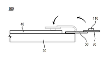
도 1 내지 도 3을 참조하면, 본 발명에 따른 디스플레이 장치(100)는 디스플레이 패널(20)과, 백플레이트(40)와, 칩온 필름((Chip on Film) 이하 COF, 30)과, 연성회로기판((Flexible Printed Circuit) 이하, FPC, 50) 등의 회로기판 및 부착수단을 포함한다.1 to 3, the
먼저, 디스플레이 패널(20)은 서브 픽셀들이 매트릭스 형태로 배열된 픽셀 어레이를 통해 영상을 표시한다. 기본 픽셀은 화이트(W), 레드(R), 그린(G), 블루(B) 서브 픽셀들 중 컬러 혼합으로 화이트 표현이 가능한 적어도 3개 서브 픽셀들로 구성될 수 있다. 예를 들면, 기본 픽셀은 R/G/B 조합의 서브 픽셀들, W/R/G 조합의 서브 픽셀들, B/W/R 조합의 서브 픽셀들, G/B/W 조합의 서브 픽셀들로 구성되거나, W/R/G/B 조합의 서브 픽셀들로 구성될 수 있다.First, the
또한 전원부를 구비하여 입력 전압을 이용하여 타이밍 컨트롤러와, 게이트 드라이버, 데이터 드라이버와, 디스플레이 패널 등과 디스플레이 장치에서 필요한 다양한 구동 전압들을 생성하여 출력한다. 예를 들면, 전원부는 데이터 드라이버 및 타이밍 컨트롤러 등에 공급되는 디지털 회로의 구동 전압과, 데이터 드라이버에 공급되는 아날로그 회로의 구동 전압과, 게이트 드라이버에서 이용되는 게이트 온 전압(게이트 하이 전압) 및 게이트 오프 전압(게이트 로우 전압) 등을 생성하여 공급한다. 전원부는 디스플레이 패널 구동 시 필요한 복수의 구동 전압(EVDD, EVSS)과, 레퍼런스 전압을 생성하여 데이터 드라이버를 통해 디스플레이 패널(20)에 공급한다.In addition, a power supply unit is provided to generate and output various driving voltages required by a timing controller, a gate driver, a data driver, a display panel, and the like, using an input voltage. For example, the power supply unit includes a driving voltage of a digital circuit supplied to a data driver and a timing controller, a driving voltage of an analog circuit supplied to a data driver, and a gate-on voltage (gate high voltage) and a gate-off voltage used in the gate driver. (Gate low voltage) and the like are generated and supplied. The power supply unit generates a plurality of driving voltages (EVDD, EVSS) and reference voltages required for driving the display panel and supplies them to the
타이밍 컨트롤러는 외부 시스템으로부터 영상 데이터 및 기초 타이밍 제어 신호들을 공급받는다. 시스템은 컴퓨터, TV 시스템, 셋탑 박스, 태블릿이나 휴대폰 등과 같은 휴대 단말기의 시스템 중 어느 하나일 수 있다. 기초 타이밍 제어 신호들은 도트 클럭, 데이터 인에이블 신호, 수직 동기 신호, 수평 동기 신호 등을 포함할 수 있다.The timing controller receives image data and basic timing control signals from an external system. The system may be any one of a system of a portable terminal such as a computer, a TV system, a set top box, a tablet or a mobile phone. The basic timing control signals may include a dot clock, a data enable signal, a vertical synchronization signal, and a horizontal synchronization signal.
타이밍 컨트롤러는 외부로부터 공급받은 기초 타이밍 제어 신호들과 내부 레지스터에 저장된 타이밍 설정 정보(스타트 타이밍, 펄스폭 등)를 이용하여 데이터 드라이버 및 게이트 드라이버의 구동 타이밍을 각각 제어하는 데이터 제어 신호들 및 게이트 제어 신호들을 생성하여 공급한다.The timing controller uses the basic timing control signals received from the outside and timing setting information (start timing, pulse width, etc.) stored in the internal registers to control the data driver signals and gate drivers, respectively, and gate control data. Generate and supply signals.
또한 디스플레이 패널(20)은 햅틱 일체형 터치스크린을 포함할 수 있고, 이 경우 디스플레이 패널 전면을 보호하는 커버 글라스(10)와 디스플레이 패널(20) 사이에 터치스크린이 위치할 수 있다. 여기서 이러한 디스플레이 패널(20)은 액정패널, 유기발광패널, 플라즈마 패널 등에 모두 적용될 수 있다. 커버 글라스(10)는 디스플레이 패널(20)의 전면에 부착되어 디스플레이 장치의 전면 외관을 형성함과 동시에 디스플레이 패널을 보호하는 기능을 수반한다.In addition, the
또한 디스플레이 패널(20)은 폴더블 디스플레이인 경우, 폴딩 라인을 따라 접힐 수 있다. 실질적으로 디스플레이 패널(20)이 접혀짐에 있어서는 특정 선에서 접히는 것이 아니라 일정 곡률을 가지고 접히게 되므로, 접힐 때 휘어지는 부분이 일정 영역으로 형성된다. 디스플레이 패널(20)은 패널 자체가 휘어지거나 굽혀질 수 있는 플렉시블(Flexible) 디스플레이 패널일 수도 있고, 패널 자체가 평판 상태로 외력에 의하여 잘 변형되지 않는 리지드(rigid)한 평판 디스플레이 패널일 수도 있다. 디스플레이 패널(20) 자체가 가요성을 가지는 플렉시블 디스플레이 패널(20)은 유기 발광 전계 디스플레이(OLED) 패널, 전기 영동 디스플레이(electrophoretic display) 패널, 또는 일렉트로 크로믹 디스플레이(electrochromic display, ECD) 패널 등으로 구현될 수 있다.Also, in the case of a foldable display, the
그리고 회로기판은 디스플레이 패널을 구동하기 위한 전기적인 신호를 인가하기 위한 것으로, 회로 패턴이 구비된 기판과 기판에 실장된 집적회로 칩(IC 칩)을 포함한다. 또한 회로기판은 집적회로가 실장되는 메인기판과, 상기 메인기판과 디스플레이 패널(20)을 연결하는 연결기판을 포함한다. 메인기판은 배선 패턴이 단층 또는 다층으로 마련된 것으로, 그 자체가 휘거나 접히기 어려운 형태인 경질의 인쇄회로기판(Printed Circuit Board, PCB)이 적용되거나 가요성을 가지는 연성인쇄회로기판(Flexible Printed Circuit Board, FPCB)이 적용될 수 있다. 연결기판은 배선 패턴이 단층 또는 다층으로 마련된 것으로, 그 자체로 휘거나 접힐 수 있는 형태인 것이 바람직하다. 연결기판으로는 FPC(Flexible Printed Circuit, 50)가 적용될 수 있으며, 필름에 칩이 실장된 COF(Chip On Film, 30)가 적용될 수도 있다.In addition, the circuit board is for applying an electrical signal to drive the display panel, and includes a circuit patterned substrate and an integrated circuit chip (IC chip) mounted on the substrate. Also, the circuit board includes a main board on which an integrated circuit is mounted, and a connecting board connecting the main board and the
백플레이트(40)는 디스플레이 패널(20)의 배면에 결합되어 디스플레이 패널(20) 배면을 지지함으로써 디스플레이 패널(20)을 외력으로부터 보호한다. 또한 백플레이트는 알루미늄이나 스테인리스 스틸 재질로 이루어져 방열기능을 제공할 수도 있다.The
도 2를 참조하면, 백플레이트(40)의 단부를 중심으로 COF(30)의 일 단부가 벤딩되면서 COF(30)와 FPC(50)가 일체로 벤딩되어 백플레이트(40)의 배면에 부착된다.Referring to FIG. 2, as one end of the
FPC(50)가 백플레이트(40)의 배면에 부착되기 위해서 FPC(50)의 배면에 제1부착수단(110)이 부착되어야 한다.In order for the
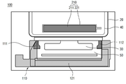
도 4a는 도 1에 나타낸 디스플레이 장치의 제1부착수단(110)을 부분적으로 확대 도시하는 부분 확대도이고, 도 4b는 도 3에 나타낸 디스플레이 장치의 제1부착수단(110)의 일부를 더 확대하여 도시하고, 확대한 부분의 A-A'단면도를 동시에 도시하는 참고도이다.FIG. 4A is a partially enlarged view partially showing the first attachment means 110 of the display device illustrated in FIG. 1, and FIG. 4B further enlarges a part of the first attachment means 110 of the display device illustrated in FIG. 3. This is a reference diagram showing A-A' cross-sectional view of an enlarged portion at the same time.
도 4a 및 도 4b를 참조하면, 제1부착수단(110)은 제1접착부재(111)와 제2접착부재(112) 및 제1라이너(121)를 포함한다.4A and 4B, the first attachment means 110 includes a first
제1접착부재(111)는 FPC(50)의 배면 일 측 가장자리 영역에 부착되고, 제2접착부재(112)는 제1접착부재(111)와 나란히 이격되어 FPC(50)의 배면 타 측 가장자리 영역에 부착된다(도 1 참조). 제1접착부재(111)와 제2접착부재(112)는 일종의 양면테이프 구조를 가지며, 보다 상세하게는 PET(Polyethylene Terephthalate) 재질의 필름을 중심으로 양 면에 점착물질을 도포된 구조를 가진다. 예컨대 감압접착제인 PSA(Pressure Sensitive Adhesive)가 적용될 수 있다.The first
제1접착부재(111)와 제2접착부재(112)는 서로 동일한 높이 또는 두께를 가지며, 제1라이너(121)에 의해 동시 부착이 이루어진다. 따라서 FPC(50)의 배면에 일일이 하나씩 접착부재를 부착하던 공정에 비하여 부착시간을 단축할 수 있는 효과가 있다.The first
도 4b와 같이, 제1라이너(121)의 배면에 각각 제1접착부재(111)와 제2접착부재(112)의 상면이 부착되어 있고, 이 상태로 FPC(50)의 배면에 정렬한 후 제1부착수단(110)의 배면 부착이 이루어진다. 그리고 제1라이너(121)는 제1접착부재(111)와 제2접착부재(112)가 부착된 후 제거되면서 제1접착부재(111)와 제2접착부재(112)의 상면에 다시 접착기능이 제공된다.As shown in Figure 4b, the upper surfaces of the first
제1라이너(121)는 제1접착부재(111)의 일 면이 부착되는 제1연장부재(122)와, 제2접착부재(112)의 일 면이 부착되는 제2연장부재(123)와, 제1연장부재(122)와 제2연장부재(123)를 서로 연결하는 제3연장부재(124)와, 제3연장부재(124)로부터 연장되어 제1라이너(121)를 제거할 수 있도록 사용자 또는 로봇이 파지하는 제4연장부재(125)를 포함한다. 그리고 제1접착부재(111)와 제2접착부재(112)의 각 타 면이 상기 상기 FPC(50)의 배면 양 측 가장자리에 부착된 후 제거된다. 즉 제1라이너(121)는 제4연장부재(125)를 파지하고 제3연장부재(124)로부터 제1연장부재(122) 또는 제2연장부재(123) 방향(D1)으로 제거된다.The
여기서 제1라이너(121)는 디스플레이 패널(20)과 COF(30) 부착영역의 길이방향과 수직한 방향으로 제거된다. 이는 디스플레이 패널(20)과 COF(30) 부착 시작 지점에 제1접착부재(111)가 위치하고, 반대편에도 디스플레이 패널(20)과 COF(30) 부착 종료 지점에 제2접착부재(112)가 위치하여 각각 제1접착부재(111)와 제2접착부재(112)를 양쪽에서 제거하는 과정에서 디스플레이 패널(20)과 COF(30)의 부착된 부분이 파손될 수 있기 때문에 제1라이너(121)의 제거 방향을 이와 수직한 방향(D1)으로 제거함으로써 손상될 위험을 방지할 수 있는 것이다.Here, the
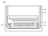
이렇게 제1라이너(121)가 제거되면, COF(30)와 FPC(50)를 디스플레이 패널(20)의 배면으로부터 벤딩영역을 따라서 벤딩하고, 백플레이트(40) 배면에 정렬하여 제1접착부재(111)와 제2접착부재(112)의 상면과 백플레이트(40) 배면의 부착이 이루어진다.When the
이때 백플레이트(40)의 배면에는 제1접착부재(111) 및 제2접착부재(112)의 부착영역과 간섭되지 않는 위치에 별도의 제2부착수단(210)이 더 구비된다.At this time, a separate second attachment means 210 is further provided at a position that does not interfere with the attachment areas of the first
제2부착수단(도 1 참조, 210)은 제3접착부재(211)와 제2라이너(221)를 포함하여 백플레이트(40) 배면 중심 영역에 부착된다. 제3접착부재(211)의 배면은 백플레이트(40) 배면에 부착되고, 제2라이너(221)가 제3접착부재(211)의 상면으로부터 제거되면서 COF(30)와 FPC(50)의 벤딩이 이루어지며, 제1접착부재(111)와 제2접착부재(112)는 백플레이트(40)의 배면에 부착되고, 제3접착부재(211)는 FPC(50)의 배면에 부착이 이루어져, 제1접착부재(111) 내지 제3접착부재(211)의 양 면 부착이 완료된다.The second attachment means (refer to FIG. 1, 210) is attached to the central region of the
그리고 제1접착부재(111) 내지 제3접착부재(211)는 서로 같은 높이 또는 두께로 부착될 수 있고, 또한 제1접착부재(111)와 제2접착부재(112)의 높이 또는 두께가 같고 제3접착부재(211)만 높이 또는 두께가 다르게 부착될 수도 있다. 이는 FPC(50)와 백플레이트(40) 사이에서 각각 제1접착부재(111) 내지 제3접착부재(211)의 부착영역 높이 또는 두께에 대응하도록 변형될 수 있다.In addition, the first
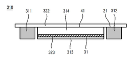
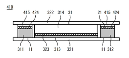
도 5는 본 발명의 제2실시예에 따른 디스플레이 장치의 배면에서 회로기판이 부착되기 전에 제3부착수단(310)이 백플레이트의 배면에 부착된 상태를 도시하는 배면도이고, 도 6a 내지 도 6d는 도 5에 나타낸 디스플레이 장치의 제3부착수단(310)의 부착 순서를 도시하는 단면도이다.5 is a rear view showing a state in which the third attaching means 310 is attached to the back surface of the back plate before the circuit board is attached from the back surface of the display device according to the second embodiment of the present invention. 6D is a cross-sectional view showing the attachment procedure of the third attachment means 310 of the display device shown in FIG. 5.
도면을 참조하면, 본 발명의 제2실시예에 따른 디스플레이 장치(300)는 백플레이트(40) 배면에 부착되는 제3부착수단(310)을 포함한다.Referring to the drawings, the
제3부착수단(310)은 적어도 둘 이상의 분리된 영역에 복수의 접착부재가 배치되고, 이들을 일체로 부착시킬 수 있다. 또한 전기한 제1실시예에서 제1부착수단(110)과 제2부착수단(도 2 참조, 210)으로 두 차례에 걸쳐 부착해야 하는 과정을 하나의 과정으로 통합하기 때문에 부착시간을 더 단축할 수 있는 효과가 있다.The third attachment means 310 may be provided with a plurality of adhesive members disposed in at least two separate regions, and may be integrally attached to them. In addition, in the first embodiment described above, since the process of attaching the two times to the first attaching
제3부착수단(310)은 제1접착부재(311)와, 제2접착부재(312)와, 제3접착부재(313)와, 제4접착부재(314)와, 제1라이너(31) 및 제2라이너(322)를 포함한다.The third attachment means 310 includes a first
이때 제1접착부재(311) 내지 제3접착부재(313)는 백플레이트(40) 배면에 부착되고, 제1접착부재(311)와 제2접착부재(312)는 동일 높이 또는 두께(이하 높이로 칭함)를 가지며, 제3접착부재(313)는 제1접착부재(311) 및 제2접착부재(312) 보다 낮은 높이를 갖기 때문에 제3접착부재(313)에는 추가적으로 제4접착부재(314)가 부착되어 제1접착부재(311) 내지 제3접착부재(313)가 제1라이너(31)와 제2라이너(322) 사이에서 동일한 높이를 갖도록 형성된다.At this time, the first
도 6a를 참조하면, 제3접착부재(313)와 제4접착부재(314) 사이에는 제3라이너(323)가 추가적으로 구비된다.Referring to FIG. 6A, a
따라서 제1접착부재(311)와 제2접착부재(312)의 높이는 동일하고, 제3접착부재(313), 제3라이너(323) 및 제4접착부재(314)를 합한 높이가 제1접착부재(311) 또는 제2접착부재(312)의 높이와 동일하다.Accordingly, the heights of the first
제3부착수단(310)의 부착순서를 살펴보면 다음과 같다.Looking at the attachment order of the third attachment means 310 is as follows.
도 6b와 같이, 제1라이너(31)를 제거하고, 도 6c 와 같이, 백플레이트(40)의 배면에 부착하면, 제1접착부재(311) 내지 제3접착부재(313)가 동시에 백플레이트(40) 배면에 부착된다. 이때 제1접착부재(311) 내지 제3접착부재(313)와 제1라이너(31) 사이에 형성된 제1접착면(11)의 접착력이 가장 작다.6B, when the
제1접착부재(311) 내지 제3접착부재(313)가 백플레이트(40) 배면에 부착된 후, 제2라이너(322)를 제거하면, 제2라이너(322)와 함께 제3라이너(323)와 제4접착부재(314)가 동시에 제거된다.After the first
여기서 제1접착부재(311)와 제2접착부재(312)의 타 면과 제2라이너(322) 사이에 마련된 제2접착면(21)의 접착력은 제3라이너(323)와 제3접착부재(313) 사이에 마련된 제3접착면(31)의 접착력과 동일한 크기를 가진다. 또한 제2접착면(21)의 접착력은 제2라이너(322)와 제4접착부재(314) 사이에 마련된 제4접착면(41)의 접착력 보다 작은 크기를 가진다. 또한 제2접착면(21)의 접착력은 제4접착부재(314)와 제2러이너 사이에 마련된 제4접착면(41)의 접착력 보다 작다. 이러한 경우 제2접착면(21)과 제4접착면(41)의 접착력이 서로 다르게 형성되어야 하기 때문에 다른 접착력을 갖도록 두 번의 점착층 도포가 이루어질 수 있다. 물론 한 번의 점착층 도포 과정에서 서로 다른 접착력의 점착층을 도포할 수도 있다.Here, the adhesive force of the second
그러면 도 6d와 같이, 백플레이트(40) 배면에 제1접착부재(311) 내지 제3접착부재(313)만 남게된다. 그리고 벤딩된 COF(30)와 함께 FPC(50)를 제1접착부재(311) 내지 제3접착부재(313)에 부착하면 벤딩이 완료된다.Then, as shown in Figure 6d, only the first
도 7a 내지 도 7d는 본 발명의 제3실시예에 따른 디스플레이 장치의 제3부착수단(310)의 부착 순서를 도시하는 단면도이다. 이하에서 전기한 도면부호와 동일한 도면부호는 동일한 구성요소를 나타낸다.7A to 7D are cross-sectional views showing an attachment procedure of the third attachment means 310 of the display device according to the third embodiment of the present invention. The same reference numerals as described above denote the same components.
도 7a 내지 도 7d를 참조하면, 본 발명의 제3실시예에 따른 디스플레이 장치는 제3부착수단(310)이 제5접착부재(415)와, 제5접착부재(415)와 제2접착부재(312) 사이에 부착되는 제4라이너(424)를 포함한다.7A to 7D, in the display device according to the third embodiment of the present invention, the third attachment means 310 includes a fifth
제1접착부재(311)의 타 면에는 제4라이너(424)가 부착되고, 제4라이너(424) 반대편에는 제5접착부재(415)가 부착되며, 제5접착부재(415)의 반대편은 제2라이너(322)에 부착된다. 물론 도 7a와 같이, 제1부착부재와 제4라이너(424) 및 제5부착부재의 높이는 제2접착부재(312)와 제4라이너(424)와 제5부착부재를 합한 높이와 같고, 이는 제3접착부재(313)와 제3라이너(323)와 제4접착부재(314)를 합한 높이와 같다.A
도 7b를 살펴보면, 먼저 제1라이너(31)가 제거된다. 그러면 도 7c와 같이, 제1접착부재(311)와 제2접착부재(312) 및 제3접착부재(313)가 백플레이트(40) 배면에 동시 부착된다.Referring to Figure 7b, first the
그리고 제2라이너(322)가 제거되면, 도 7d와 같이 제2라이너(322)와 함께 제3라이너(323)와 제4접착부재(314)가 제거되고, 동시에 제4라이너(424)와 제5접착부재(415)가 제거된다.Then, when the
이후 FPC(50) 부착 순서는 제2실시예와 동일하므로 중복 설명은 생략한다.Since the order of attaching the
여기서 제1접착부재(311) 내지 제3접착부재(313)의 각 일 면과 제1라이너(31) 사이에 마련된 제1접착면(11)의 접착력은 제1접착부재(311) 내지 제3접착부재(313)의 각 타 면과 부착되는 제3라이너(323) 및 제4라이너(424) 사이에 마련된 제2접착면(21)의 접착력 보다 작은 크기를 가진다.Here, the adhesive force of the first
또한 제2접착면(21)의 접착력은 제4접착부재(314)와 제5접착부재(415) 각각과 제2라이너(322) 사이에 마련된 제3접착면(31)의 접착력 보다 작은 크기를 가진다.In addition, the adhesive force of the second
따라서 제4접착부재(314)와 제2라이너(322) 사이 또는 제5접착부재(415)와 제2라이너(322) 사이에 마련된 제3접착면(31)은 가장 강한 접착력을 가지며, 각각의 제2접착면(21)의 접착력이 제3접착면(31)의 접착력보다는 작지만 제2접착면(21)끼리의 접착력은 서로 동일하게 형성된다.Therefore, the third
이렇게 부착 위치에 따라서 접착력을 달리함으로써 각 라이너들이 분리되는 과정에서 제거되는 부분과 남아 있어야 하는 부분을 명확하게 분리시킬 수 있으며, 각 접착부재를 한 번에 백플레이트(40) 배면 상에 부착할 수 있다.By varying the adhesive force according to the attachment position in this way, it is possible to clearly separate the part to be removed from the process in which the respective liners are separated and to remain, and each adhesive member can be attached on the back surface of the
따라서, 본 발명의 디스플레이 장치에 따르면 디스플레이 패널 배면에 COF를 부착하기 위해서 COF 배면에 구비되는 제1접착부재와 제2접착부재를 동시에 부착할 수 있기 때문에 제1부착수단을 부착하고 제거하는 시간을 단축할 수 있고, 부착수단을 부착한 후에 COF의 배면에서 라이너를 제거하는 방향을 변경함으로써 라이너의 제거에 따라 발생하는 접착력으로 인하여 COF와 디스플레이 패널 사이에 손상이 발생하는 것을 방지할 수 있으며, 부착수단의 양 면에 부착된 라이너와 접착부재 간의 접착력을 달리하여 서로 다른 높이 또는 두께를 가지는 접착부재를 용이하게 부착할 수 있는 효과가 있다.Therefore, according to the display device of the present invention, since the first adhesive member and the second adhesive member provided on the rear surface of the COF can be attached at the same time to attach the COF to the display panel, the time for attaching and removing the first attachment means is reduced. It can be shortened, and after attaching the attachment means, by changing the direction of removing the liner from the rear of the COF, it is possible to prevent damage from occurring between the COF and the display panel due to the adhesive force generated by the removal of the liner. There is an effect of easily attaching the adhesive members having different heights or thicknesses by varying the adhesive force between the liner and the adhesive members attached to both sides of the means.
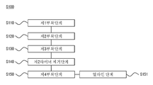
도 8은 본 발명의 실시예에 따른 부착수단을 구비한 디스플레이 장치의 제조방법을 도시하는 블록도이다.8 is a block diagram showing a method of manufacturing a display device having an attachment means according to an embodiment of the present invention.
도 8을 참조하면, 본 발명의 실시예에 따른 부착수단을 구비한 디스플레이 장치의 제조방법(S100)은 전기한 제3실시예에 따른 부착수단(310)을 구비한 디스플레이 장치의 제조방법을 일 예로 설명한다.Referring to FIG. 8, a method for manufacturing a display device with an attachment means according to an embodiment of the present invention (S100) is a method for manufacturing a display device with an attachment means 310 according to the third embodiment described above. Described as an example.
부착수단을 구비한 디스플레이 장치의 제조방법(S100)은 제1부착단계(S110)와, 제2부착단계(S120), 제3부착단계(S130), 제2라이너 제거단계(S140), 제4부착단계(S150)를 포함한다.The manufacturing method (S100) of the display device having the attachment means includes a first attachment step (S110), a second attachment step (S120), a third attachment step (S130), a second liner removal step (S140), and a fourth. Attachment step (S150).
먼저, 제1부착단계(S110)는 디스플레이패널의 배면에 COF를 부착한다. 그리고 제1부착단계(S110)가 완료되면, 제2부착단계(S120)는 COF의 배면에 백플레이트를 부착한다.First, in the first attachment step (S110), COF is attached to the rear surface of the display panel. Then, when the first attaching step (S110) is completed, the second attaching step (S120) attaches the back plate to the rear surface of the COF.
그리고 제2부착단계(S120)가 완료되면, 부착수단(310)의 제1라이너(321)를 제거하고, 제1접착부재(311)와 제2접착부재(312) 및 제3접착부재(313)의 일 면을 백플레이트(40) 배면의 설정 위치에 부착하는 제3부착단계(S130)가 진행된다.Then, when the second attachment step (S120) is completed, the
여기서 제3부착단계(S130)의 설정 위치는 제1접착부재(311)와 제2접착부재(312)가 각각 FPC(50)의 배면 양 측 가장자리 부분에 대응하고, 제3접착부재(313)가 제1접착부재(311)와 제2접착부재(312) 사이에서 COF(30)의 위치에 대응한다. 물론 제3부착단계(S130)는 COF(30)가 백플레이트(40)의 배면으로 벤딩되었을 때 각각 제1접착부재(311) 내지 제3접착부재(313)의 부착 위치에도 대응한다.Here, the set position of the third attaching step (S130) corresponds to the first
제3부착단계(S130)가 완료되면, 부착수단(310)의 제2라이너(322)를 제거하는 제2라이너 제거단계(S140)가 이루어진다.When the third attaching step S130 is completed, a second liner removing step S140 of removing the
제2라이너 제거단계(S140)에서는 제2라이너(322)와 부착된 제4접착부재(314)와 제5접착부재(415)는 제거된다. 물론 제4접착부재(314)와 부착된 제3라이너(323)와, 제5접착부재(415)와 부착된 제4라이너(424) 역시 제거된다.In the second liner removal step (S140), the
제2라이너(322)를 제거하면, 도 3과 같이, COF를 벤딩하여 제1접착부재(311)와 제2접착부재(312) 및 제3접착부재(313)의 타 면이 각각 FPC(50)의 배면과 COF(30)의 배면에 부착되는 제4부착단계(S150)가 이루어진다.When the
이때 제4부착단계(S150)은 제1접착부재(311)와 제2접착부재(312) 및 제3접착부재(313)의 타 면이 각각 FPC(50) 및 COF(30)의 배면 설정 위치에 부착되도록 얼라인 단계(S151)가 진행된다.At this time, in the fourth attachment step (S150), the other surfaces of the first
얼라인 단계(S151)는 제1접착부재(311)와 제2접착부재(312)의 타 면이 각각 FPC(50)의 양 측 가장자리에 대응하도록 정렬되고, 제3접착부재(313)의 타 면이 COF(30)의 배면 중심에 대응하도록 정렬된다.In the alignment step (S151), the other surfaces of the first
또한 제4부착단계(S150)에서 제1접착부재(311) 또는 제2접착부재(312)의 높이 또는 두께가 제3접착부재(313)의 높이 또는 두께 보다 크지만, FPC(50)의 높이 또는 두께 보다 큰 COF(30)가 제3접착부재(313)에 부착되면서 부착 높이가 같아지게 된다.In addition, the height or thickness of the first
각 부착단계에서 접착면에 형성된 접착력에 대한 설명은 전기한 바와 같으므로 중복설명은 생략한다.The description of the adhesive force formed on the adhesive surface in each attaching step is the same as described above, so a duplicate description is omitted.
이러한 부착수단을 구비한 디스플레이 장치의 제조방법(S100)에 따르면, 각 접착부재의 양 면에 부착된 라이너와 접착부재 간의 접착력을 서로 다르게 함으로써 서로 다른 높이 또는 두께를 가지는 접착부재를 용이하게 부착할 수 있는 효과가 있다.According to the manufacturing method (S100) of the display device having such attachment means, the adhesive force having different heights or thicknesses can be easily attached by making the adhesive force between the liner and the adhesive members attached to both sides of each adhesive member different. It has the effect.
이상에서 본 발명의 기술적 사상을 예시하기 위해 구체적인 실시 예로 도면을 참고하여 설명하였으나, 본 발명은 상기와 같이 구체적인 실시 예와 동일한 구성 및 작용효과에만 국한되지 않고, 여러 가지 변형된 예가 본 발명의 범위를 벗어나지 않는 한도 내에서 실시될 수 있다. 따라서, 그와 같은 변형예도 본 발명의 범위에 속하는 것으로 간주해야 하며, 본 발명의 진정한 기술적 보호 범위는 후술하는 특허청구범위의 기술적 사상에 의해 결정되어야 할 것이다.In the above, in order to illustrate the technical spirit of the present invention, a specific embodiment has been described with reference to the drawings, but the present invention is not limited to the same configuration and effect as the specific embodiment as described above, and various modified examples are the scope of the present invention. It can be carried out within the limits that do not deviate. Therefore, such a modified example should be regarded as belonging to the scope of the present invention, and the true technical protection scope of the present invention should be determined by the technical spirit of the following claims.
100 : 디스플레이 장치
110 : 제1부착수단
120 : 제2부착수단
130 : 제3부착수단
140 : 제4부착수단100: display device
110: first attachment means
120: second attachment means
130: third attachment means
140: fourth attachment means
Claims (16)
상기 FPC의 배면 일 측 가장자리에 부착되는 제1접착부재;
상기 FPC의 배면에서 상기 일 측 가장자리와 이격된 타 측 가장자리에 부착되는 제2접착부재 및
상기 제1접착부재와 제2접착부재를 설정 간격으로 유지하면서 상기 FPC 상에 동시에 부착시키는 제1라이너;
를 포함하는 부착수단.In the FPC coupled to one end of the COF coupled to the back of the display panel, and the attachment means for attaching a back plate coupled to the back of the COF while the COF is bent,
A first adhesive member attached to one side edge of the rear surface of the FPC;
A second adhesive member attached to the other side edge spaced from the one side edge on the rear surface of the FPC, and
A first liner for simultaneously attaching the first adhesive member and the second adhesive member to the FPC while maintaining a predetermined interval;
Attachment means comprising a.
상기 제1라이너는,
상기 제1접착부재의 일 면이 부착되는 제1연장부재와,
상기 제2접착부재의 일 면이 부착되는 제2연장부재와,
상기 제1연장부재와 제2연장부재를 서로 연결하는 제3연장부재와,
상기 제3연장부재로부터 연장되어 상기 제1라이너를 제거할 수 있도록 사용자 또는 로봇이 파지하는 제4연장부재를 포함하고,
상기 제1저착부재와 제2접착부재의 각 타 면이 상기 상기 FPC의 배면 양 측 가장자리에 부착된 후 제거되는 부착수단.The method according to claim 1,
The first liner,
A first extension member to which one side of the first adhesive member is attached,
A second extension member to which one side of the second adhesive member is attached,
A third extension member connecting the first extension member and the second extension member to each other,
A fourth extension member extended from the third extension member and held by a user or a robot to remove the first liner,
Attachment means that is removed after each other surface of the first adhesive member and the second adhesive member is attached to both side edges of the rear surface of the FPC.
상기 백플레이트의 배면 중심 영역에 부착되는 제3접착부재와,
상기 제3접착부재의 일 면에 부착되어 상기 제3접착부재의 타 면을 상기 백플레이트의 배면 중심 영역에 부착한 후 제거되는 제2라이너를 더 포함하는 부착수단.The method according to claim 2,
A third adhesive member attached to the central area of the back surface of the back plate,
Attachment means further comprises a second liner attached to one surface of the third adhesive member and then removed after attaching the other surface of the third adhesive member to the central area of the back surface of the back plate.
상기 제3접착부재는 상기 COF가 벤딩되면서 상기 제1접착부재와 제2접착부재 사이에 배치되고, 서로 이격되도록 배치되는 부착수단.The method according to claim 3,
The third adhesive member is an attachment means disposed between the first adhesive member and the second adhesive member while the COF is bent and spaced apart from each other.
상기 제1접착부재와 제2접착부재는 서로 같은 높이 또는 두께를 갖도록 부착되고, 상기 제3접착부재는 상기 제1접착부재와 서로 다른 높이 또는 두께를 갖도록 부착되는 부착수단.The method according to claim 4,
The first adhesive member and the second adhesive member are attached to have the same height or thickness, and the third adhesive member is attached to the first adhesive member to have a different height or thickness.
상기 제1라이너는,
상기 디스플레이 패널과 COF의 부착영역 길이방향과 수직한 방향으로 상기 제1접착부재와 제2접착부재로부터 동시에 제거되는 부착수단.The method according to claim 1,
The first liner,
Attachment means that is simultaneously removed from the first adhesive member and the second adhesive member in a direction perpendicular to the longitudinal direction of the display panel and the COF.
상기 FPC의 배면 일 측 가장자리에 대응하도록 상기 백플레이트 배면에 부착되는 제1접착부재;
상기 FPC의 배면에서 상기 일 측 가장자리와 이격된 타 측 가장자리에 대응하도록 상기 백플레이트 배면에 부착되는 제2접착부재;
상기 백플레이트의 배면 중심 영역에 부착되며, 상기 제1접착부재 또는 제2접착부재 보다 높이가 낮거나 또는 두께가 작은 제3접착부재;
상기 제1접착부재와 제2접착부재 및 제3접착부재의 각 일면을 동시에 부착시키는 제1라이너;
상기 제1접착부재와 제2접착부재 및 제3접착부재의 각 타면을 동시에 부착시키도록 상기 제1라이너와 대향하도록 배치되는 제2라이너 및
상기 제3접착부재와 제2라이너 사이에 개재되어 상기 제1접착부재 또는 제2접착부재와 제3접착부재의 높이 또는 두께를 보상하는 제4접착부재;
를 포함하는 부착수단.In the FPC coupled to one end of the COF coupled to the back of the display panel, and the attachment means for attaching a back plate coupled to the back of the COF while the COF is bent,
A first adhesive member attached to the back surface of the back plate to correspond to one edge of the back surface of the FPC;
A second adhesive member attached to the back side of the back plate to correspond to the other side edge spaced from the one side edge on the rear surface of the FPC;
A third adhesive member attached to a central area of the rear surface of the back plate, having a lower height or a smaller thickness than the first adhesive member or the second adhesive member;
A first liner which simultaneously attaches each surface of the first adhesive member, the second adhesive member, and the third adhesive member;
A second liner disposed to face the first liner to simultaneously attach the other surfaces of the first adhesive member, the second adhesive member, and the third adhesive member, and
A fourth adhesive member interposed between the third adhesive member and the second liner to compensate for the height or thickness of the first adhesive member or the second adhesive member and the third adhesive member;
Attachment means comprising a.
상기 제3접착부재와 제4접착부재 사이에 개재되는 제3라이너를 더 포함하는 부착수단.The method according to claim 7,
Attachment means further comprising a third liner interposed between the third adhesive member and the fourth adhesive member.
상기 제2라이너와 제1접착부재 사이 및 상기 제2라이너와 제2접착부재 사이에 각각 구비되는 제5접착부재와,
상기 제5접착부재와 제2접착부재 사이에 부착되는 제4라이너를 더 포함하는 부착수단.The method according to claim 8,
A fifth adhesive member provided between the second liner and the first adhesive member and between the second liner and the second adhesive member,
Attachment means further comprising a fourth liner attached between the fifth adhesive member and the second adhesive member.
상기 제1접착부재 내지 제3접착부재의 각 일 면과 상기 제1라이너 사이에 마련된 제1접착면의 접착력은 상기 제1접착부재 내지 제3접착부재의 각 타면과 부착되는 상기 제3라이너 및 제4라이너 사이에 마련된 제2접착면의 접착력 보다 작고,
상기 제2접착면의 접착력은 상기 제4접착부재와 제5접착부재와 상기 제2라이너 사이에 마련된 제3접착면의 접착력 보다 작은 부착수단.The method according to claim 8,
The adhesive strength of the first adhesive surface provided between each first surface of the first adhesive member to the third adhesive member and the first liner is the third liner attached to each other surface of the first adhesive member to the third adhesive member, and Less than the adhesion of the second adhesive surface provided between the fourth liner,
The adhesive force of the second adhesive surface is smaller than the adhesive force of the third adhesive surface provided between the fourth adhesive member and the fifth adhesive member and the second liner.
상기 COF 배면에 백플레이트를 부착시키는 제2부착단계;
상기 청구항 7 내지 청구항 10 중 어느 한 청구항에 기재된 부착수단의 제1라이너를 제거하고 제1접착부재와 제2접착부재 및 제3접착부재의 일 면을 상기 백플레이트 배면의 설정된 위치에 부착하는 제3부착단계 및
상기 부착수단의 제2라이너를 제거하는 제2라이너 제거단계;
상기 제2라이너를 제거한 뒤, 상기 COF를 벤딩하여 상기 부착수단에 COF 및 상기 COF의 일 단부에 결합된 FPC를 부착하는 제4부착단계;
를 포함하는 부착수단을 구비한 디스플레이 장치의 제조방법.A first attaching step of attaching COF to the back side of the display panel;
A second attachment step of attaching a back plate to the back side of the COF;
Claims 7 to 10 of claim 1 to remove the first liner of the attachment means according to any one of the first adhesive member and the second adhesive member and one surface of the third adhesive member attached to the set position of the back plate back surface 3 Attachment step and
A second liner removing step of removing the second liner of the attachment means;
A fourth attaching step of removing the second liner and bending the COF to attach the COF and the FPC coupled to one end of the COF to the attaching means;
Method of manufacturing a display device having an attachment means comprising a.
상기 제4부착단계는,
상기 제1접착부재와 제2접착부재 및 제3접착부재의 각 타 면과 상기 FPC 또는 COF의 부착 위치를 정렬하는 얼라인 단계를 포함하는 부착수단을 구비한 디스플레이 장치의 제조방법.The method according to claim 11,
The fourth attachment step,
Method of manufacturing a display device having an attachment means comprising an alignment step of aligning the attachment position of the FPC or COF with each other surface of the first adhesive member, the second adhesive member and the third adhesive member.
상기 얼라인 단계는
상기 제1접착부재와 제2접착부재의 각 타면과 상기 FPC의 배면 양 측 가장자리가 부착되도록 정렬하고,
상기 제3접착부재의 타면과 상기 COF의 배면이 부착되도록 정렬하는 부착수단을 구비한 디스플레이 장치의 제조방법.The method according to claim 12,
The alignment step
Align each other surface of the first adhesive member and the second adhesive member and the edges on both sides of the rear surface of the FPC,
Method of manufacturing a display device having an attachment means for aligning the other surface of the third adhesive member and the rear surface of the COF to be attached.
상기 제2라이너 제거단계는,
상기 제1접착부재 또는 제2접착부재와 부착된 제4라이너 및 제5접착부재와, 상기 제3접착부재와 부착된 제3라이너와 제4접착부재가 상기 제2라이너 제거와 동시에 제거되는 부착수단을 구비한 디스플레이 장치의 제조방법.The method according to claim 11,
The second liner removal step,
The first liner and the second liner attached to the fourth liner and the fifth liner, and the third liner attached to the third liner and the fourth liner attached to the second liner are removed simultaneously with the attachment Method of manufacturing a display device having a means.
상기 제1접착부재 내지 제3접착부재의 각 일 면과 상기 제1라이너 사이에 마련된 제1접착면의 접착력은 나머지 접착면들의 접착력 보다 작은 부착수단을 구비한 디스플레이 장치의 제조방법.The method according to claim 11,
A method of manufacturing a display device having an attachment means having an adhesive force of a first adhesive surface provided between each one surface of the first to third adhesive members and the first liner smaller than that of the other adhesive surfaces.
상기 제1접착부재 내지 제3접착부재의 각 타면과 부착되는 상기 제3라이너 및 제4라이너 사이에 마련된 제2접착면의 접착력은 상기 제4접착부재 및 제5접착부재와 상기 제2라이너 사이에 마련된 제3접착면의 접착력 보다 작은 부착수단을 구비한 디스플레이 장치의 제조방법.The method according to claim 14,
The adhesive force of the second adhesive surface provided between the third and fourth liners attached to each other surface of the first to third adhesive members is between the fourth and fifth adhesive members and the second liner. Method of manufacturing a display device having an attachment means smaller than the adhesive force of the third adhesive surface provided in.
Priority Applications (1)
| Application Number | Priority Date | Filing Date | Title |
|---|---|---|---|
| KR1020180164084A KR20200075427A (en) | 2018-12-18 | 2018-12-18 | Adhesion means and Manufacturing method of Display Device |
Applications Claiming Priority (1)
| Application Number | Priority Date | Filing Date | Title |
|---|---|---|---|
| KR1020180164084A KR20200075427A (en) | 2018-12-18 | 2018-12-18 | Adhesion means and Manufacturing method of Display Device |
Publications (1)
| Publication Number | Publication Date |
|---|---|
| KR20200075427A true KR20200075427A (en) | 2020-06-26 |
Family
ID=71136285
Family Applications (1)
| Application Number | Title | Priority Date | Filing Date |
|---|---|---|---|
| KR1020180164084A KR20200075427A (en) | 2018-12-18 | 2018-12-18 | Adhesion means and Manufacturing method of Display Device |
Country Status (1)
| Country | Link |
|---|---|
| KR (1) | KR20200075427A (en) |
-
2018
- 2018-12-18 KR KR1020180164084A patent/KR20200075427A/en unknown
Similar Documents
| Publication | Publication Date | Title |
|---|---|---|
| KR102606222B1 (en) | Display device and display panel | |
| US11304294B2 (en) | Display device | |
| CN108257508B (en) | Flexible display device and method of manufacturing the same | |
| CN108257509B (en) | Flexible display device | |
| CN106932979B (en) | Array substrate and display device comprising same | |
| US9285835B2 (en) | Flexible display device and method of manufacturing the same | |
| US9560761B2 (en) | Curved display | |
| KR101956549B1 (en) | Flexible display device and method for manufacturing thereof | |
| US8085379B2 (en) | Circuit board and display device having the same | |
| US11178779B2 (en) | Display device | |
| KR20140139762A (en) | Flexible display apparatus | |
| US10575403B2 (en) | Display device | |
| KR20140108826A (en) | Flexible display device and method for manufacturing thereof | |
| KR20180036857A (en) | Flexible display | |
| US9343025B2 (en) | Display device | |
| US20180190233A1 (en) | Shift register and display device including the same | |
| US20170082982A1 (en) | Display device and smart watch | |
| US10108057B2 (en) | Electro-optical device and electronic apparatus | |
| CN111754866A (en) | Display device | |
| US20180088387A1 (en) | Electrooptical device and electronic apparatus | |
| WO2019080736A1 (en) | Method of bonding integrated circuit chip to display panel, and display apparatus | |
| US20060001819A1 (en) | Display device | |
| KR20170133573A (en) | Flexible display panel and flexible display device | |
| KR101345279B1 (en) | Image display device and method of fabricating the same | |
| KR20200075427A (en) | Adhesion means and Manufacturing method of Display Device |