KR20200073991A - Oxygen Water Production Equipment - Google Patents
Oxygen Water Production Equipment Download PDFInfo
- Publication number
- KR20200073991A KR20200073991A KR1020190147810A KR20190147810A KR20200073991A KR 20200073991 A KR20200073991 A KR 20200073991A KR 1020190147810 A KR1020190147810 A KR 1020190147810A KR 20190147810 A KR20190147810 A KR 20190147810A KR 20200073991 A KR20200073991 A KR 20200073991A
- Authority
- KR
- South Korea
- Prior art keywords
- oxygen
- water
- inlet
- motor pump
- flow path
- Prior art date
Links
Images


Classifications
-
- B01F3/04099—
-
- B—PERFORMING OPERATIONS; TRANSPORTING
- B01—PHYSICAL OR CHEMICAL PROCESSES OR APPARATUS IN GENERAL
- B01F—MIXING, e.g. DISSOLVING, EMULSIFYING OR DISPERSING
- B01F23/00—Mixing according to the phases to be mixed, e.g. dispersing or emulsifying
- B01F23/20—Mixing gases with liquids
- B01F23/23—Mixing gases with liquids by introducing gases into liquid media, e.g. for producing aerated liquids
-
- B01F15/00538—
-
- B01F15/0292—
-
- B—PERFORMING OPERATIONS; TRANSPORTING
- B01—PHYSICAL OR CHEMICAL PROCESSES OR APPARATUS IN GENERAL
- B01F—MIXING, e.g. DISSOLVING, EMULSIFYING OR DISPERSING
- B01F23/00—Mixing according to the phases to be mixed, e.g. dispersing or emulsifying
- B01F23/20—Mixing gases with liquids
- B01F23/23—Mixing gases with liquids by introducing gases into liquid media, e.g. for producing aerated liquids
- B01F23/2366—Parts; Accessories
-
- B—PERFORMING OPERATIONS; TRANSPORTING
- B01—PHYSICAL OR CHEMICAL PROCESSES OR APPARATUS IN GENERAL
- B01F—MIXING, e.g. DISSOLVING, EMULSIFYING OR DISPERSING
- B01F23/00—Mixing according to the phases to be mixed, e.g. dispersing or emulsifying
- B01F23/20—Mixing gases with liquids
- B01F23/23—Mixing gases with liquids by introducing gases into liquid media, e.g. for producing aerated liquids
- B01F23/237—Mixing gases with liquids by introducing gases into liquid media, e.g. for producing aerated liquids characterised by the physical or chemical properties of gases or vapours introduced in the liquid media
- B01F23/2376—Mixing gases with liquids by introducing gases into liquid media, e.g. for producing aerated liquids characterised by the physical or chemical properties of gases or vapours introduced in the liquid media characterised by the gas being introduced
- B01F23/23761—Aerating, i.e. introducing oxygen containing gas in liquids
- B01F23/237612—Oxygen
-
- B01F3/04829—
-
- B—PERFORMING OPERATIONS; TRANSPORTING
- B01—PHYSICAL OR CHEMICAL PROCESSES OR APPARATUS IN GENERAL
- B01F—MIXING, e.g. DISSOLVING, EMULSIFYING OR DISPERSING
- B01F35/00—Accessories for mixers; Auxiliary operations or auxiliary devices; Parts or details of general application
- B01F35/30—Driving arrangements; Transmissions; Couplings; Brakes
- B01F35/32—Driving arrangements
- B01F35/32005—Type of drive
- B01F35/3204—Motor driven, i.e. by means of an electric or IC motor
-
- B—PERFORMING OPERATIONS; TRANSPORTING
- B01—PHYSICAL OR CHEMICAL PROCESSES OR APPARATUS IN GENERAL
- B01F—MIXING, e.g. DISSOLVING, EMULSIFYING OR DISPERSING
- B01F35/00—Accessories for mixers; Auxiliary operations or auxiliary devices; Parts or details of general application
- B01F35/75—Discharge mechanisms
- B01F35/754—Discharge mechanisms characterised by the means for discharging the components from the mixer
- B01F35/7547—Discharge mechanisms characterised by the means for discharging the components from the mixer using valves, gates, orifices or openings
-
- B01F2003/04879—
Landscapes
- Chemical & Material Sciences (AREA)
- Chemical Kinetics & Catalysis (AREA)
Abstract
Description
본 발명은 산소수 제조장치에 관한 것으로, 더욱 상세하게는 식물을 재배하거나 폐수를 정화하기 위해 물에 산소를 혼합 응축시켜 용존 산소량을 증가시킨 물(이하 '산소수'라 한다)을 만드는 산소수 제조장치에 관한 것이다.The present invention relates to an apparatus for producing oxygen water, and more specifically, oxygen water to make water (hereinafter referred to as'oxygen water') by increasing the amount of dissolved oxygen by mixing and condensing oxygen in water to cultivate a plant or purify wastewater. It relates to a manufacturing apparatus.
일반적으로 산소수는 물에 산소를 용해시켜 물속에 포함된 산소량을 증가시킨 것으로, 이러한 산소수는 식물의 성장에 유익한 것으로 알려져 다양한 분야에 널리 이용되고 있다.In general, oxygen water dissolves oxygen in water to increase the amount of oxygen contained in water, and such oxygen water is widely used in various fields because it is known to be beneficial for plant growth.
상기와 같은 산소수는 물에 산소를 용해시키는 방법에 따라 다양한 장치가 개발되어 사용되고 있는데, 이러한 산소수 제조장치의 종래 기술로는 공개특허공보 제2015-0132799호의 산소수 제조방법 및 산소수 제조장치(이하 '특허문헌'이라 한다)가 개시되어 있다.Various devices have been developed and used according to the method of dissolving oxygen in water, and the prior art of such an oxygen water production device is the oxygen water production method and the oxygen water production device of Korean Patent Publication No. 2015-0132799. (Hereinafter referred to as'patent document') is disclosed.
상기 특허문헌에 개시된 산소수 제조장치는, 본체케이스; 상기 본체케이스에 외부로부터 유입된 원수를 1차 저수하는 내부저수조; 상기 내부저수조로부터 연장된 냉수배출라인의 길이중간에 순환펌프를 갖추고, 상기 냉수배출라인과 삼방밸브를 매개로 연결되는 산소공급라인을 갖는 산소발생기를 갖추어 상기 냉수배출라인을 통해 출수되는 냉수에 산소를 혼합하여 산소수를 생성하는 산소수 생성부; 상기 삼방밸브를 매개로 연결되어 산소수가 순환되는 제1 산소수 순환라인과 연결되어 산소수에 용해된 산소의 용존율을 높이는 용존기; 상기 용존기로부터 연장된 제2 산소수 순환라인과 연결되고, 상기 본체케이스의 외부면에 투명소재로 이루어진 몸체 일부가 외부로 노출되도록 구비되고, 상기 내부저수조에 산소수를 공급하도록 제3 산소수 순환라인을 매개로 상기 내부저수조와 연결되는 외부저수조 및 상기 내부저수조에 저수된 산소수의 온도를 직접 또는 간접적으로 측정하는 온도센서에 의해서 측정된 값을 근거로 하여 내부저수조에 구비되는 냉각코일의 작동을 제어하며, 상기 산소발생기의 작동을 제어하는 제어기를 포함하여 구성된다.Oxygen water production apparatus disclosed in the patent document, the main body case; An internal water storage tank that primarily stores raw water flowing in from the outside into the main body case; Equipped with a circulation pump in the middle of the length of the cold water discharge line extending from the internal reservoir, an oxygen generator having an oxygen supply line connected through the cold water discharge line and a three-way valve is provided, and oxygen is supplied to the cold water discharged through the cold water discharge line. An oxygen water generating unit for mixing to generate oxygen water; A dissolver connected to the first oxygen water circulation line connected to the three-way valve through which oxygen water is circulated to increase the dissolution rate of oxygen dissolved in oxygen water; It is connected to the second oxygen water circulation line extending from the dissolved machine, and is provided so that a part of the body made of a transparent material is exposed to the outside on the outer surface of the body case, and the third oxygen water is supplied to supply the oxygen water to the internal reservoir. Based on the value measured by the temperature sensor that directly or indirectly measures the temperature of the external water tank connected to the internal water tank and the internal water tank via a circulation line, the cooling coil provided in the internal water tank It controls the operation, it is configured to include a controller for controlling the operation of the oxygen generator.
그러나 상기 특허문헌에 개시된 산소수 제조장치는 용존기가 단순히 내경이 큰 유로 쪽에서 상대적으로 내경이 작은 유로 쪽으로 흐르도록 하는 과정에서 자연스럽게 압력이 상승되도록 하여 물속에 혼합된 산소가 더욱 응축되도록 하는 것이나, 이러한 용존기의 유로를 따라 물이 흐르는 시간이 짧기 때문에 물속에 산소를 응축시키는 효과가 충분히 발현되지 못하는 문제가 있다.However, the oxygen water production apparatus disclosed in the patent document allows the pressure to rise naturally in a process in which the dissolved gas simply flows from a passage having a larger inner diameter to a passage having a smaller inner diameter, thereby further condensing oxygen mixed in water. There is a problem in that the effect of condensing oxygen in water is not sufficiently expressed because the time for water to flow along the flow path of the dissolved group is short.
이 때문에 종래의 산소수 제조장치를 통해 제조된 산소수의 경우 산소가 물속에 기포 상태(버블)로 잔존하게 되면서 물속에서 쉽게 빠져나와 용존산소량이 증가된 상태로 유지되는 시간이 짧고, 그 결과 식물에 공급하는 과정에서 산소가 빠져나오게 되면서 산소수를 공급하여 식물을 재배하게 됨에 따라 기대되는 유용한 효과가 크게 경감되는 문제가 있다.For this reason, in the case of oxygen water produced through a conventional oxygen water production apparatus, oxygen is easily left out of the water while remaining in a bubble state (bubble) in the water, and the amount of dissolved oxygen is maintained in an increased state, resulting in shorter plants. In the process of supplying oxygen, as the oxygen is released, there is a problem in that the expected useful effect is greatly reduced as the plant is grown by supplying oxygen water.
따라서 산소가 물속에 용존된 상태로 장시간 유지될 수 있도록 하는 산소수 제조장치의 개발이 요구된다.Therefore, there is a need for the development of an oxygen water production apparatus that allows oxygen to be maintained in a dissolved state for a long time.
본 발명은 상기와 같은 종래의 산소수 제조장치가 가지는 문제점을 해결하기 위해 안출된 것으로, 본 발명이 해결하고자 하는 과제는 물에 산소를 혼합한 다음 유속차를 이용하여 무수한 와류를 만들어 물속에 산소를 용해시키는 산소수 제조장치를 제공하는 것이다.The present invention has been devised to solve the problems of the conventional oxygen water production apparatus as described above, and the problem to be solved by the present invention is to mix oxygen with water and then create countless vortices using a flow rate difference to make oxygen in the water. It is to provide a device for producing oxygen water to dissolve.
상기의 과제를 해결하기 위한 본 발명에 따른 산소수 제조장치는, 내부에 소정량의 물이 저장되는 저수탱크; 물유입구, 산소유입구 및 제1, 2 배출구가 구비되면서 상기 저수탱크에 저장된 물을 상기 물유입구를 통해 홉인하는 모터펌프; 상기 모터펌프로 산소를 공급하는 산소발생기; 상기 모터펌프를 통해 공급되는 물과 산소가 혼합된 산소혼합수를 산소수로 만드는 산소응축기를 포함하고, 상기 모터펌프는, 상기 물유입구의 일측에 상기 산소유입구가 형성되며, 상기 제1, 2 배출구는 밸브를 통해 유로가 전환되도록 구성되는 것을 특징으로 한다.Oxygen water production apparatus according to the present invention for solving the above problems, a reservoir for storing a predetermined amount of water therein; A motor pump which is equipped with a water inlet, an oxygen inlet, and first and second outlets and hops in water stored in the water storage tank through the water inlet; An oxygen generator that supplies oxygen to the motor pump; And an oxygen condenser that converts the oxygen mixed water in which water and oxygen supplied through the motor pump into oxygen water, and the motor pump is formed with the oxygen inlet on one side of the water inlet, and the first and second The outlet is characterized in that it is configured to switch the flow path through the valve.
그리고 본 발명은 상기 제1 배출구에 상기 저수탱크와 연결되는 1차 회수유로가 연결되어 상기 모터펌프를 통과하여 배출되는 산소혼합수가 선택적으로 상기 저수탱크로 회수되도록 하는 것을 또 다른 특징으로 한다.In addition, another aspect of the present invention is that a first recovery passage connected to the water storage tank is connected to the first discharge port so that oxygen mixed water discharged through the motor pump is selectively recovered to the water storage tank.
또한, 본 발명은 상기 산소발생기가 상기 모터펌프의 속도에 비례하여 산소 공급량이 조절되는 것을 또 다른 특징으로 한다.In addition, another aspect of the present invention is that the oxygen generator is adjusted in proportion to the speed of the motor pump.
이에 더해 본 발명은 상기 산소유입구가 상기 물유입구의 지름에 비해 상대적으로 지름이 작게 형성되는 것을 또 다른 특징으로 한다.In addition to this, the present invention is characterized in that the oxygen inlet is formed to have a relatively small diameter compared to the diameter of the water inlet.
그리고 본 발명은 상기 산소응축기에 상기 모터펌프를 통해 산소혼합수가 공급되는 유입구와, 상기 산소응축기를 통과하여 산소수가 배출되는 배출구가 구비되고, 상기 배출구에는, 제조된 산소수가 유로를 따라 배출되도록 하는 산소수 배출유로가 설치되며, 상기 산소수 배출유로에는, 밸브의 유로 전환을 통해 산소수가 상기 저수탱크에 회수되도록 하는 2차 회수유로가 설치되는 것을 또 다른 특징으로 한다.In addition, the present invention is provided with an inlet through which the oxygen mixed water is supplied through the motor pump to the oxygen condenser, and an outlet through which the oxygen water is discharged through the oxygen condenser, wherein the produced oxygen water is discharged along the flow path. Another feature is that an oxygen water discharge flow path is installed, and a second recovery flow path is installed in the oxygen water discharge flow path so that oxygen water is recovered in the reservoir tank through switching of a flow path of a valve.
본 발명에 따르면, 모터펌프를 통해 물과 산소가 1차로 혼합되어 산소혼합수가 제조되고, 이렇게 제조된 산소혼합수는 유로를 따라 산소응축기로 공급되어 소정 간격을 두고 설치되는 복수 개의 유로구획판을 차례로 통과하면서 반복적으로 유속차가 발생하여 무수한 와류가 형성되며, 이에 의해 물속의 산소 버블의 크기가 작게 분해되면서 산소가 물속에 쉽게 용해될 수 있다.According to the present invention, water and oxygen are first mixed through a motor pump to produce oxygen mixed water, and the produced oxygen mixed water is supplied to an oxygen condenser along a flow path to provide a plurality of flow path partition plates installed at predetermined intervals. As the flow rate difference occurs repeatedly in succession, countless vortices are formed, whereby the size of the oxygen bubbles in the water is decomposed to a small extent, and oxygen can be easily dissolved in the water.
도 1은 본 발명에 따른 산소수 제조장치의 예를 보인 구성도.
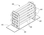
도 2 및 도 3은 본 발명에 따른 산소응축기의 예를 보인 사시도.
도 4는 본 발명에 따른 메인배관 내부에 삽입배관과 유로구획판이 삽입 설치된 예를 보인 단면도.
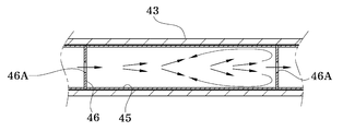
도 5는 본 발명에 따른 산소혼합수가 유로구획판을 통과하여 흐르는 예를 보인 도면.
도 6은 본 발명에 따른 유로구획판에 승압관이 설치된 예를 보인 단면도.
도 7은 본 발명에 따른 산소응축기에 나선연결관이 설치된 예를 보인 도면.1 is a block diagram showing an example of an apparatus for producing oxygen water according to the present invention.
2 and 3 are perspective views showing an example of an oxygen condenser according to the present invention.
4 is a cross-sectional view showing an example in which the insertion pipe and the flow path partition plate are installed inside the main pipe according to the present invention.
5 is a view showing an example of the oxygen mixed water flowing through the flow path partition plate according to the present invention.
Figure 6 is a cross-sectional view showing an example of the pressure pipe is installed in the flow path partition plate according to the present invention.
7 is a view showing an example in which a spiral connector is installed in the oxygen condenser according to the present invention.
이하에서는 본 발명의 바람직한 실시예를 도시한 첨부도면에 따라 상세하게 설명한다.Hereinafter will be described in detail in accordance with the accompanying drawings showing a preferred embodiment of the present invention.
본 발명은 물에 산소를 혼합한 다음 유속차를 이용하여 무수한 와류를 만들어 물속에 산소를 용해시키는 산소수 제조장치를 제공하고자 하는 것으로, 이러한 본 발명은 도 1에 도시된 바와 같이 저수탱크(10), 모터펌프(20), 산소발생기(30) 및 산소응축기(40)를 포함한다.The present invention is to provide an apparatus for producing an oxygen water in which oxygen is dissolved in water by mixing oxygen with water and then making countless vortices using a flow rate difference, and the present invention provides a storage tank (10) as shown in FIG. ), a
저수탱크(10)는 농가에서 식물을 재배하기 위한 소정량의 물이 저장되는 구성이다.The
이러한 저수탱크(10)는 수도관과 연결되어 내부로 소정량의 물이 저장되도록 내부에 수용공간이 형성된 탱크로 이루어지면서, 하부 일측에는 내부와 연통되어 내부에 저장된 물을 후술되는 모터펌프(20) 쪽으로 공급하는 배수구(도면부호 없음)가 구비된다.The
그리고 저수탱크(10)의 상부 쪽에는 산소혼합수 또는 산소수가 저수탱크(10)의 내부로 회수되도록 하는 1, 2차 회수유로(L4, L6)의 일단이 내부로 소정 길이 삽입되도록 설치된다.In addition, one end of the primary and secondary recovery passages L4 and L6 to allow the oxygen mixed water or oxygen water to be recovered into the
모터펌프(20)는 저수탱크(10)에 저장된 물과 후술되는 산소발생기(30)를 통해 공급되는 산소를 혼합시켜 후술되는 산소응축기(40) 쪽으로 공급하는 구성이다.The
이러한 모터펌프(20)는 도 1에 도시된 바와 같이 일측에는 물유입구(21)가 구비되고, 타측에는 물유입구(21)를 통해 모터펌프(20)의 내측으로 유입된 물이 배출되는 제1, 2 배출구(23, 24)가 구비된다.As shown in FIG. 1, the
이때 제1 배출구(23)에는 후술되는 산소응축기(40) 쪽으로 산소혼합수가 공급되도록 산소혼합수 공급유로(L3)가 연결되고, 제2 배출구(23)에는 저수탱크(10)로 산소혼합수가 회수(공급)되도록 하는 1차 회수유로(L4)가 연결된다.At this time, the
여기서 제1, 2 배출구(23, 24)는 수동 또는 자동 밸브를 통해 유로의 전환이 가능하도록 구성되고, 이를 통해 제1 배출구(23) 또는 제2 배출구(24) 중에서 선택된 어느 일측의 유로를 통해 산소혼합수가 배출되게 된다.Here, the first and
또한, 물유입구(21)의 일측에는 후술되는 산소발생기(30)를 통해 공급되는 산소가 모터펌프(20)의 내부로 공급되기 전에 물과 혼합되도록 하는 산소유입구(22)가 구비되고, 이러한 산소유입구(22)는 물유입구(21)의 지름에 비해 상대적으로 지름이 작게 형성되며, 이에 의해 물유입구(21)를 통해 흐르는 물속으로 높은 압력의 산소가 공급되게 되면서 물과 산소가 더욱 쉽게 혼합되게 된다.In addition, one side of the
산소발생기(30)는 공기 중에 포함된 오염물질과 질소 등을 제거하여 고농도의 산소를 만드는 구성이다.The
이러한 산소발생기(30)는 공지된 다양한 구조의 산소발생기 중에서 선택되어 구성되고, 따라서 산소발생기(30)의 구성에 대한 상세한 설명은 생략한다.The
산소발생기(30)는 모터펌프(20)의 구동 속도에 비례하여 산소 발생량이 자동으로 조절되도록 구성되고, 이에 의해 후술되는 산소응축기(40) 쪽으로 공급되는 산소혼합수 내의 산소 혼합 비율이 일정하게 유지되면서 제조되는 산소수 내의 용존산소량이 소정 범위 내로 유지되도록 한다.The
산소응축기(40)는 모터펌프(20)를 통해 산소가 혼합되어 공급되는 산소혼합수에 대해 유속차를 이용하여 무수한 와류가 발생되도록 하고, 이를 통해 물속에 혼합된 산소 버블의 크기를 작게 만들어 산소가 물에 쉽게 용해될 수 있도록 하여 산소수를 만드는 구성이다.The
이러한 산소응축기(40)는 도 2 및 도 3에 도시된 바와 같이 소정 넓이를 가지는 바닥판(41)과, 상기 바닥판(41)에 수직으로 소정 간격 이격되어 한 쌍이 설치되는 설치판(42)과, 상기 한 쌍의 설치판(42)을 관통하여 설치되도록 소정 길이를 가지는 복수 개의 메인배관(43)과, 상기 복수 개의 메인배관(43)을 사행상의 유로를 가지도록 연결하는 U자 모양의 연결배관(44)과, 상기 메인배관(43)의 내부에 삽입 설치되는 복수 개의 삽입배관(45) 및 상기 복수 개의 삽입배관(45) 사이에 설치되는 소정 두께의 유로구획판(46)을 포함한다.2 and 3, the
이때 복수 개의 연결배관(44)을 통해 사행상의 유로로 연결되는 메인배관(43)의 일단은 산소혼합수 공급유로(L3)와 연결되는 유입구(IF)가 되고, 타단은 산소수 배출유로(L5)와 연결되는 배출구(OF)가 된다.At this time, one end of the
또한, 삽입배관(45)과 유로구획판(46)의 외측면 지름은 상기 메인배관(43)의 내측면 지름에 대응되도록 형성되고, 유로구획판(46)에는 도 4에 도시된 바와 같이 메인배관(43) 내부로 공급된 산소혼합수가 통과되도록 하는 소정 지름의 구멍(46A)이 형성된다.In addition, the diameter of the outer surface of the
이때 구멍(46A)이 유로구획판(46)의 가운데 부분에 1개가 형성되거나, 또는 가운데를 중심으로 방사상으로 복수 개가 형성되고, 이러한 구멍(46A)에 의해 형성되는 통로의 면적이 유로구획판(46)의 전체면적 대비 1/2이하가 되도록 형성되는데, 이에 의해 삽입배관(45) 내부 공간을 흐르는 산소혼합수의 유속과 구멍(46A)을 통과하는 과정에서 상승되는 산소혼합수의 유속 간에 적정의 유속 차이가 확실하게 담보되게 된다.At this time, one
이에 의해 메인배관(43)을 통해 산소혼합수가 공급되면, 도 5에 도시된 바와 같이 메인배관(43) 내부에 삽입된 삽입배관(45) 상에서는 상대적으로 넓은 공간에 의해 산소혼합수의 유속이 느려지고, 산소혼합수가 구멍(46A)을 통과할 때에는 유속이 빨라지게 되며, 그 결과 삽입배관(45) 상에서 빠른 유속의 산소혼합수와 느린 유속의 산소혼합수 간에 와류가 발생하게 되어 물속에 혼합된 산소 버블이 와류에 의해 작게 분해되게 되고, 이러한 과정이 메인배관(43)에 의해 형성되는 사행상 유로를 따라 흐르는 동안 여러 번 반복하여 발생하게 되면서 자연스럽게 산소혼합수의 산소 버블의 크기가 매우 작게 만들어지면서 산소가 물에 용해되게 된다.Accordingly, when the oxygen mixed water is supplied through the
또한, 유로구획판(46)의 구멍(46A)에는 도 6에 도시된 바와 같이 2~3㎝의 길이를 가지는 승압관(46B)이 수평 방향으로 길이를 가지도록 설치되고, 이에 의해 구멍(46A)을 통과하는 산소혼합수가 승압관(46B)을 통과하는 과정에서 유속이 더욱 빨라지게 되면서 삽입배관(45) 내부 공간으로 분사되는 압력이 상승되고, 그 결과 삽입배관(45) 내부에서 더욱 큰 유속 차이로 인해 물과 산소 버블 간에 강한 와류가 형성되게 되면서 산소 버블의 크기가 작아지도록 더욱 빠르게 분해되게 된다.In addition, in the
이에 더해 소정 길이를 가지는 메인배관(43)의 내부에 삽입배관(45)과 유로구획판(46)을 차례로 삽입하는 것으로 메인배관(43)의 내부에 소정 간격을 두고 복수 개의 유로구획판(46)을 쉽게 설치할 수 있으면서도 필요에 따라 분리(분해)하여 세척 등의 유지 보수를 쉽게 할 수 있게 된다.In addition, by inserting the
또한, 메인배관(43)의 타단에는 도 7에 도시된 바와 같이 주름이 형성된 소정 길이의 주름관(47)의 일단이 연결될 수 있는데, 이러한 주름관(47)은 메인배관(43)의 외측면을 감싸도록 나선 모양으로 권취된 다음, 타단에 산소수 배출유로(L5)가 연결된다.In addition, the other end of the
상기와 같은 주름관(47)을 통해 메인배관(43)이 외부로 노출되는 것이 방지되고, 이와 동시에 메인배관(43) 내부의 산소혼합수 및 산소수가 외부 온도의 영향으로 온도가 크게 상승하거나 낮아지는 것이 방지된다.The
이하에서는 본 발명의 산소수 제조장치가 사용되는 예에 따라 설명한다.Hereinafter will be described according to an example in which the oxygen water production apparatus of the present invention is used.
도 1을 참고하면, 저수탱크(10)의 배수구와 모터펌프(20)의 물유입구(21)를 연결하도록 물공급유로(L1)가 설치되고, 모터펌프(20)의 산소유입구(22)와 산소발생기(30)를 연결하도록 산소공급유로(L2)가 설치된다.Referring to FIG. 1, a water supply channel L1 is installed to connect the drain port of the
그리고 제1 배출구(23)와 산소응축기(40)의 유입구(IF)를 연결하도록 산소혼합수 공급유로(L3)가 설치되고, 제2 배출구(24)에는 1차 회수유로(L4)가 연결되어 저수탱크(10)의 상부 쪽으로 물이 회수되도록 연결된다.In addition, an oxygen mixed water supply channel L3 is installed to connect the
또한, 산소응축기(40)의 배출구(OF)에는 산소수 배출유로(L5)가 연결되고, 이러한 산소수 배출유로(L5)의 자유단에는 산소수를 분사시키기 위한 분사노즐(N)이 설치되거나, 또는 별도의 배관, 저장탱크 등과 연결된다.In addition, the outlet (OF) of the
이때 산소수 배출유로(L5) 상에는 3방향 밸브(V)가 설치된 다음, 2차 회수유로(L6)가 설치되고, 이러한 2차 회수유로(L6)의 선단은 저장탱크(10)의 상부 쪽으로 물이 회수되도록 연결된다.At this time, a three-way valve (V) is installed on the oxygen water discharge passage (L5), and then a secondary recovery passage (L6) is installed, and the tip of the secondary recovery passage (L6) is water toward the upper portion of the storage tank (10). It is connected to be recovered.
그런 다음 모터펌프(20)와 산소발생기(30)에 전원을 공급하면, 저수탱크(10)에 저장된 물이 모터펌프(20)에 의해 물공급유로(L1)를 따라 모터펌프(20) 쪽으로 흡인되고, 이와 동시에 산소발생기(30)에서 생성된 산소가 산소공급유로(L2)를 통해 모터펌프(20) 쪽으로 공급되면서 물과 산소가 혼합된 산소혼합수가 만들어지게 되며, 이러한 산소혼합수는 산소혼합수 공급유로(L3)를 통해 산소응축기(40) 쪽으로 공급된다.Then, when power is supplied to the
이때 초기 구동시에는 모터펌프(20)를 통해 공급되는 물의 양과 산소발생기(30)를 통해 공급되는 산소 공급량이 설정된 비율에 맞지 않지 않아 식물 재배 를 위한 기준에 부합되는 산소수를 제조하기에 충분하지 못할 수 있고, 따라서 초기 구동시에는 소정 시간 동안(대략 5~10분) 제1 배출구(23)를 대신하여 제2 배출구(24) 쪽으로 산소혼합수가 배출되도록 유로가 선택되어 1차 회수유로(L4)를 따라 저수탱크(10) 쪽으로 회수되도록 제어된다.At this time, during the initial driving, the amount of water supplied through the
그런 다음, 제1 배출구(23)를 통해 산소혼합수가 산소응축기(40) 쪽으로 공급되도록 유로가 선택되고, 이에 의해 산소혼합수가 산소응축기(40)의 메인배관(43)을 따라 사행상으로 흐르면서 삽입배관(45)과 유로구획판(46)에 의해 형성되는 유속차로 인해 무수한 와류가 형성되어 산소 버블이 물에 쉽게 용해될 수 있을 정도로 작게 부서짐과 동시에 물에 용해되어 산소수가 제조되게 되며, 이렇게 제조되는 산소수는 배출구(OF)와 산소수 배출유로(L5)를 따라 배출되어 식물 재배 용도로 사용된다.Then, the flow path is selected so that the oxygen mixture water is supplied toward the
이때 제조된 산소수가 곧바로 식물 재배 용도로 사용되지 않을 때에는 밸브(V)를 통해 유로를 전환하여 산소수를 저수탱크(10)로 회수시키고, 이렇게 소정 시간 물을 순환시키게 되면 저수탱크(10)에 저장된 물이 전체적으로 산소수로 바뀌게 된다.At this time, when the produced oxygen water is not directly used for plant cultivation purposes, the flow path is switched through the valve V to recover the oxygen water to the
이후 필요시 저수탱크(10)에 저장된 산소수를 식물에 공급하여 사용되도록 한다.Then, if necessary, the oxygen water stored in the
이상 설명한 바와 같이 본 발명은 모터펌프를 통해 물과 산소가 1차로 혼합되어 산소혼합수가 제조되고, 이렇게 제조된 산소혼합수는 유로를 따라 산소응축기로 공급되어 소정 간격을 두고 설치되는 복수 개의 유로구획판을 차례로 통과하면서 반복적으로 유속차가 발생하여 무수한 와류가 형성되며, 이에 의해 물속의 산소가 작게 분해되면서 산소가 물속에 효과적으로 용해되게 된다.As described above, according to the present invention, water and oxygen are first mixed through a motor pump to prepare oxygen mixture water, and the thus prepared oxygen mixture water is supplied to an oxygen condenser along a flow path to install a plurality of flow path sections installed at predetermined intervals. As the flow rate difference occurs repeatedly through the plate one after another, innumerable vortices are formed, whereby oxygen in the water is decomposed to a small extent and oxygen is effectively dissolved in the water.
위에서는 설명의 편의를 위해 바람직한 실시예를 도시한 도면과 도면에 나타난 구성에 도면부호와 명칭을 부여하여 설명하였으나, 이는 본 발명에 따른 하나의 실시예로서 도면상에 나타난 형상과 부여된 명칭에 국한되어 그 권리범위가 해석되어서는 안 될 것이며, 발명의 설명으로부터 예측 가능한 다양한 형상으로의 변경과 동일한 작용을 하는 구성으로의 단순 치환은 통상의 기술자가 용이하게 실시하기 위해 변경 가능한 범위 내에 있음은 지극히 자명하다고 볼 것이다.In the above, for convenience of description, the drawings showing the preferred embodiments and the components shown in the drawings have been described with reference numerals and names, but this is an embodiment according to the present invention. It should be construed that the scope of the right should not be interpreted, and a simple substitution from the description of the invention to a configuration that functions the same as the change to various predictable shapes is within the range that can be changed by a person skilled in the art for easy implementation. You will see it as self-evident.
10: 저수탱크
20: 모터펌프
21: 물유입구
22: 산소유입구
23: 제1 배출구
24: 제2 배출구
30: 산소발생기
40: 산소응축기
41: 바닥판
42: 설치판
43: 메인배관
44: 연결배관
45: 삽입배관
46: 유로구획판
46A: 구멍
46B: 승압관
47: 주름관
IF: 유입구
L1: 물공급유로
L2: 산소공급유로
L3: 산소혼합수 공급유로
L4: 1차 회수유로
L5: 산소수 배출유로
L6: 2차 회수유로
N: 분사노즐
OF: 배출구
V: 밸브10: reservoir tank 20: motor pump
21: water inlet 22: oxygen inlet
23: first outlet 24: second outlet
30: oxygen generator 40: oxygen condenser
41: bottom plate 42: mounting plate
43: main piping 44: connecting piping
45: insertion pipe 46: flow path partition plate
46A:
47: corrugated pipe IF: inlet
L1: Water supply channel L2: Oxygen supply channel
L3: Oxygen mixed water supply channel L4: Primary recovery channel
L5: Oxygen water discharge flow path L6: Secondary recovery flow path
N: Spray nozzle OF: Outlet
V: valve
Claims (5)
물유입구(21), 산소유입구(22) 및 제1, 2 배출구(23, 24)가 구비되면서 상기 저수탱크(10)에 저장된 물을 상기 물유입구(21)를 통해 홉인하는 모터펌프(20);
상기 모터펌프(20)로 산소를 공급하는 산소발생기(30);
상기 모터펌프(20)를 통해 공급되는 물과 산소가 혼합된 산소혼합수를 산소수로 만드는 산소응축기(40);
를 포함하고,
상기 모터펌프(20)는,
상기 물유입구(21)의 일측에 상기 산소유입구(22)가 형성되며, 상기 제1, 2 배출구(23, 24)는 밸브를 통해 유로가 전환되도록 구성되는 것을 특징으로 하는 산소수 제조장치.
A storage tank 10 in which a predetermined amount of water is stored;
A water inlet 21, an oxygen inlet 22 and first and second outlets 23 and 24 are provided, and a motor pump 20 hops water stored in the reservoir 10 through the water inlet 21. ;
An oxygen generator 30 that supplies oxygen to the motor pump 20;
An oxygen condenser 40 for converting the oxygen mixed water in which water and oxygen supplied through the motor pump 20 into oxygen water;
Including,
The motor pump 20,
The oxygen inlet 22 is formed on one side of the water inlet 21, and the first and second outlets 23 and 24 are oxygen water production devices characterized in that the flow path is switched through a valve.
상기 제1 배출구(24)에는,
상기 저수탱크(10)와 연결되는 1차 회수유로(L4)가 연결되어 상기 모터펌프(20)를 통과하여 배출되는 산소혼합수가 선택적으로 상기 저수탱크(10)로 회수되도록 하는 것을 특징으로 하는 산소수 제조장치.
The method according to claim 1,
In the first outlet 24,
Oxygen, characterized in that the primary recovery flow path (L4) connected to the water storage tank (10) is connected so that the oxygen mixed water discharged through the motor pump (20) is selectively recovered to the water storage tank (10) Water manufacturing equipment.
상기 산소발생기(30)는,
상기 모터펌프(20)의 속도에 비례하여 산소 공급량이 조절되는 것을 특징으로 하는 산소수 제조장치.
The method according to claim 1,
The oxygen generator 30,
Oxygen water production apparatus characterized in that the oxygen supply amount is adjusted in proportion to the speed of the motor pump (20).
상기 산소유입구(22)는,
상기 물유입구(21)의 지름에 비해 상대적으로 지름이 작게 형성되는 것을 특징으로 하는 산소수 제조장치.
The method according to claim 1,
The oxygen inlet 22,
Oxygen water production apparatus characterized in that the diameter is formed relatively smaller than the diameter of the water inlet (21).
상기 산소응축기(40)에는,
상기 모터펌프(20)를 통해 산소혼합수가 공급되는 유입구(IF)와, 상기 산소응축기(40)를 통과하여 산소수가 배출되는 배출구(OF)가 구비되고,
상기 배출구(OF)에는,
제조된 산소수가 유로를 따라 배출되도록 하는 산소수 배출유로(L5)가 설치되며,
상기 산소수 배출유로(L5)에는,
밸브(V)의 유로 전환을 통해 산소수가 상기 저수탱크(10)에 회수되도록 하는 2차 회수유로(L6)가 설치되는 것을 특징으로 하는 산소수 제조장치.The method according to claim 1,
In the oxygen condenser 40,
An inlet (IF) through which the oxygen mixed water is supplied through the motor pump 20 and an outlet (OF) through which the oxygen water is discharged through the oxygen condenser 40 are provided,
In the outlet (OF),
An oxygen water discharge flow path (L5) is installed to discharge the produced oxygen water along the flow path,
In the oxygen water discharge passage (L5),
Oxygen water production apparatus characterized in that the secondary recovery flow path (L6) is installed to allow the oxygen water to be recovered in the water storage tank (10) through switching of the valve (V).
Priority Applications (1)
| Application Number | Priority Date | Filing Date | Title |
|---|---|---|---|
| KR1020190147810A KR102178397B1 (en) | 2019-11-18 | 2019-11-18 | Oxygen Water Production Equipment |
Applications Claiming Priority (1)
| Application Number | Priority Date | Filing Date | Title |
|---|---|---|---|
| KR1020190147810A KR102178397B1 (en) | 2019-11-18 | 2019-11-18 | Oxygen Water Production Equipment |
Publications (2)
| Publication Number | Publication Date |
|---|---|
| KR20200073991A true KR20200073991A (en) | 2020-06-24 |
| KR102178397B1 KR102178397B1 (en) | 2020-11-13 |
Family
ID=71408071
Family Applications (1)
| Application Number | Title | Priority Date | Filing Date |
|---|---|---|---|
| KR1020190147810A KR102178397B1 (en) | 2019-11-18 | 2019-11-18 | Oxygen Water Production Equipment |
Country Status (1)
| Country | Link |
|---|---|
| KR (1) | KR102178397B1 (en) |
Citations (7)
| Publication number | Priority date | Publication date | Assignee | Title |
|---|---|---|---|---|
| JP2001054725A (en) * | 1999-06-30 | 2001-02-27 | Praxair Technol Inc | Production of liquid having supersaturated oxygen |
| KR100678489B1 (en) | 2005-07-19 | 2007-02-02 | 케미코아 주식회사 | Apparatus for preparing oxygen dissolved water and process for preparing oxygen dissolved water |
| KR20100011477U (en) * | 2010-03-17 | 2010-11-24 | 양승해 | Apparatus for manufacturing of oxygen water |
| KR101033262B1 (en) | 2010-10-14 | 2011-05-09 | 미진정공(주) | Oxygen water manufacturing device |
| KR101370129B1 (en) | 2013-09-24 | 2014-03-26 | (주)이노게이트 | Hydrogen abundant water making apparatus with function to adjust dissolved hydrogen |
| KR20150085862A (en) * | 2014-01-16 | 2015-07-27 | 부산가톨릭대학교 산학협력단 | GAS AND Liquid MIXING DEVICE FOR WATER TREATMENT |
| KR20150132799A (en) | 2014-05-16 | 2015-11-26 | 선바이오투판매주식회사 | Method for Fabricating the Oxygen Water and Oxygen Water Fabricating Apparatus |
-
2019
- 2019-11-18 KR KR1020190147810A patent/KR102178397B1/en active IP Right Grant
Patent Citations (7)
| Publication number | Priority date | Publication date | Assignee | Title |
|---|---|---|---|---|
| JP2001054725A (en) * | 1999-06-30 | 2001-02-27 | Praxair Technol Inc | Production of liquid having supersaturated oxygen |
| KR100678489B1 (en) | 2005-07-19 | 2007-02-02 | 케미코아 주식회사 | Apparatus for preparing oxygen dissolved water and process for preparing oxygen dissolved water |
| KR20100011477U (en) * | 2010-03-17 | 2010-11-24 | 양승해 | Apparatus for manufacturing of oxygen water |
| KR101033262B1 (en) | 2010-10-14 | 2011-05-09 | 미진정공(주) | Oxygen water manufacturing device |
| KR101370129B1 (en) | 2013-09-24 | 2014-03-26 | (주)이노게이트 | Hydrogen abundant water making apparatus with function to adjust dissolved hydrogen |
| KR20150085862A (en) * | 2014-01-16 | 2015-07-27 | 부산가톨릭대학교 산학협력단 | GAS AND Liquid MIXING DEVICE FOR WATER TREATMENT |
| KR20150132799A (en) | 2014-05-16 | 2015-11-26 | 선바이오투판매주식회사 | Method for Fabricating the Oxygen Water and Oxygen Water Fabricating Apparatus |
Also Published As
| Publication number | Publication date |
|---|---|
| KR102178397B1 (en) | 2020-11-13 |
Similar Documents
| Publication | Publication Date | Title |
|---|---|---|
| US10173175B2 (en) | Integrated gas sparger for an immersed membrane | |
| US5674312A (en) | Injection of soluble gas in a liquid stream and removal of residual undissolved gas | |
| ES2384694T3 (en) | Membrane cleaning with air driven pump | |
| JP2021510116A (en) | Cavitation member of micro bubble generator, micro bubble generator and washing equipment | |
| JP2022027952A (en) | Liquid supply facility | |
| KR200211673Y1 (en) | Apparatus for producing disolved ozone water | |
| CN104870377A (en) | Air diffusion device, air diffusion method, and water treatment device | |
| CA2928247A1 (en) | Microbubble generating device and contaminated water purifying system provided with microbubble generating device | |
| KR102178397B1 (en) | Oxygen Water Production Equipment | |
| AU2021435297B2 (en) | Method and systems for oxygenation of water bodies | |
| JP2006304714A (en) | High-concentration oxygen foam water feeder, and plant cultivation apparatus using the same | |
| KR100773103B1 (en) | Apparatus for dissolution of carbon dioxide for water treatment | |
| KR200384685Y1 (en) | Apparatus for dissolving gas | |
| KR101350893B1 (en) | apparatus for supplying and regulating nutrient solution automatically | |
| JPH1066962A (en) | Sewage treating device | |
| CN111359443A (en) | Submerged membrane module integrated with aerator and using method thereof | |
| RU142965U1 (en) | DRINKING WATER TREATMENT PLANT | |
| JP2009044985A (en) | Hydroponics system | |
| CN202542941U (en) | Efficient gas-liquid mixed aeration device | |
| KR101638317B1 (en) | Injecter apparatus of suppling an oxygen | |
| JP2004174287A (en) | Apparatus and method for purifying water | |
| JP4075009B2 (en) | Oxygen dissolver | |
| KR101370758B1 (en) | Water-purifying system using gas-liquid mixing device of high concentrations | |
| CN106430540A (en) | Sewage treatment equipment | |
| KR101125646B1 (en) | Device dissolving oxygen |
Legal Events
| Date | Code | Title | Description |
|---|---|---|---|
| A302 | Request for accelerated examination | ||
| G15R | Request for early publication | ||
| E902 | Notification of reason for refusal | ||
| E701 | Decision to grant or registration of patent right | ||
| GRNT | Written decision to grant |