KR20200072257A - Vacuum adiabatic body and refrigerator - Google Patents
Vacuum adiabatic body and refrigerator Download PDFInfo
- Publication number
- KR20200072257A KR20200072257A KR1020180160236A KR20180160236A KR20200072257A KR 20200072257 A KR20200072257 A KR 20200072257A KR 1020180160236 A KR1020180160236 A KR 1020180160236A KR 20180160236 A KR20180160236 A KR 20180160236A KR 20200072257 A KR20200072257 A KR 20200072257A
- Authority
- KR
- South Korea
- Prior art keywords
- plate member
- frame
- space
- vacuum
- machine room
- Prior art date
Links
Images


Classifications
-
- F—MECHANICAL ENGINEERING; LIGHTING; HEATING; WEAPONS; BLASTING
- F25—REFRIGERATION OR COOLING; COMBINED HEATING AND REFRIGERATION SYSTEMS; HEAT PUMP SYSTEMS; MANUFACTURE OR STORAGE OF ICE; LIQUEFACTION SOLIDIFICATION OF GASES
- F25D—REFRIGERATORS; COLD ROOMS; ICE-BOXES; COOLING OR FREEZING APPARATUS NOT OTHERWISE PROVIDED FOR
- F25D23/00—General constructional features
- F25D23/06—Walls
- F25D23/062—Walls defining a cabinet
-
- F—MECHANICAL ENGINEERING; LIGHTING; HEATING; WEAPONS; BLASTING
- F25—REFRIGERATION OR COOLING; COMBINED HEATING AND REFRIGERATION SYSTEMS; HEAT PUMP SYSTEMS; MANUFACTURE OR STORAGE OF ICE; LIQUEFACTION SOLIDIFICATION OF GASES
- F25D—REFRIGERATORS; COLD ROOMS; ICE-BOXES; COOLING OR FREEZING APPARATUS NOT OTHERWISE PROVIDED FOR
- F25D23/00—General constructional features
- F25D23/06—Walls
- F25D23/065—Details
-
- F—MECHANICAL ENGINEERING; LIGHTING; HEATING; WEAPONS; BLASTING
- F16—ENGINEERING ELEMENTS AND UNITS; GENERAL MEASURES FOR PRODUCING AND MAINTAINING EFFECTIVE FUNCTIONING OF MACHINES OR INSTALLATIONS; THERMAL INSULATION IN GENERAL
- F16L—PIPES; JOINTS OR FITTINGS FOR PIPES; SUPPORTS FOR PIPES, CABLES OR PROTECTIVE TUBING; MEANS FOR THERMAL INSULATION IN GENERAL
- F16L59/00—Thermal insulation in general
- F16L59/02—Shape or form of insulating materials, with or without coverings integral with the insulating materials
-
- F—MECHANICAL ENGINEERING; LIGHTING; HEATING; WEAPONS; BLASTING
- F16—ENGINEERING ELEMENTS AND UNITS; GENERAL MEASURES FOR PRODUCING AND MAINTAINING EFFECTIVE FUNCTIONING OF MACHINES OR INSTALLATIONS; THERMAL INSULATION IN GENERAL
- F16L—PIPES; JOINTS OR FITTINGS FOR PIPES; SUPPORTS FOR PIPES, CABLES OR PROTECTIVE TUBING; MEANS FOR THERMAL INSULATION IN GENERAL
- F16L59/00—Thermal insulation in general
- F16L59/06—Arrangements using an air layer or vacuum
- F16L59/065—Arrangements using an air layer or vacuum using vacuum
-
- F—MECHANICAL ENGINEERING; LIGHTING; HEATING; WEAPONS; BLASTING
- F25—REFRIGERATION OR COOLING; COMBINED HEATING AND REFRIGERATION SYSTEMS; HEAT PUMP SYSTEMS; MANUFACTURE OR STORAGE OF ICE; LIQUEFACTION SOLIDIFICATION OF GASES
- F25D—REFRIGERATORS; COLD ROOMS; ICE-BOXES; COOLING OR FREEZING APPARATUS NOT OTHERWISE PROVIDED FOR
- F25D23/00—General constructional features
- F25D23/006—General constructional features for mounting refrigerating machinery components
-
- F—MECHANICAL ENGINEERING; LIGHTING; HEATING; WEAPONS; BLASTING
- F25—REFRIGERATION OR COOLING; COMBINED HEATING AND REFRIGERATION SYSTEMS; HEAT PUMP SYSTEMS; MANUFACTURE OR STORAGE OF ICE; LIQUEFACTION SOLIDIFICATION OF GASES
- F25D—REFRIGERATORS; COLD ROOMS; ICE-BOXES; COOLING OR FREEZING APPARATUS NOT OTHERWISE PROVIDED FOR
- F25D23/00—General constructional features
- F25D23/02—Doors; Covers
-
- F—MECHANICAL ENGINEERING; LIGHTING; HEATING; WEAPONS; BLASTING
- F25—REFRIGERATION OR COOLING; COMBINED HEATING AND REFRIGERATION SYSTEMS; HEAT PUMP SYSTEMS; MANUFACTURE OR STORAGE OF ICE; LIQUEFACTION SOLIDIFICATION OF GASES
- F25D—REFRIGERATORS; COLD ROOMS; ICE-BOXES; COOLING OR FREEZING APPARATUS NOT OTHERWISE PROVIDED FOR
- F25D23/00—General constructional features
- F25D23/06—Walls
- F25D23/062—Walls defining a cabinet
- F25D23/063—Walls defining a cabinet formed by an assembly of panels
-
- F—MECHANICAL ENGINEERING; LIGHTING; HEATING; WEAPONS; BLASTING
- F25—REFRIGERATION OR COOLING; COMBINED HEATING AND REFRIGERATION SYSTEMS; HEAT PUMP SYSTEMS; MANUFACTURE OR STORAGE OF ICE; LIQUEFACTION SOLIDIFICATION OF GASES
- F25D—REFRIGERATORS; COLD ROOMS; ICE-BOXES; COOLING OR FREEZING APPARATUS NOT OTHERWISE PROVIDED FOR
- F25D2201/00—Insulation
- F25D2201/10—Insulation with respect to heat
- F25D2201/14—Insulation with respect to heat using subatmospheric pressure
Abstract
Description
본 발명은 진공단열체 및 냉장고에 관한 것이다. The present invention relates to a vacuum insulator and a refrigerator.
진공단열체는 몸체의 내부를 진공으로 유지하여 열전달을 억제하는 물품이다. 상기 진공단열체는 대류 및 전도에 의한 열전달을 줄일 수 있기 때문에 온장장치 및 냉장장치에 적용될 수 있다. 한편, 종래 냉장고에 적용되는 단열방식은 냉장과 냉동에 따라서 차이는 있지만 대략 30센티미터가 넘는 두께의 발포 폴리우레탄 단열벽을 제공하는 것이 일반적인 방식이었다. 그러나, 이로써 냉장고의 내부 용적이 줄어드는 문제점이 있다. The vacuum insulator is an article that suppresses heat transfer by maintaining the inside of the body in a vacuum. The vacuum insulator can be applied to a warming and refrigerating device because it can reduce heat transfer due to convection and conduction. On the other hand, the insulation method applied to the conventional refrigerator has a difference depending on refrigeration and freezing, but it was a general method to provide a foamed polyurethane insulation wall having a thickness of approximately 30 cm or more. However, there is a problem in that the internal volume of the refrigerator is reduced.
냉장고의 내부 용적을 늘리기 위하여 상기 냉장고에 진공단열체를 적용하고자 하는 시도가 있다. There is an attempt to apply a vacuum insulator to the refrigerator to increase the interior volume of the refrigerator.
먼저, 본 출원인의 등록특허 10-0343719(인용문헌 1)가 있다. 상기 등록특허에 따르면 진공단열패널(Vacuum adiabatic panel)을 제작하고, 상기 진공단열패널을 냉장고의 벽에 내장하고, 상기 진공단열패널의 외부를 스티로폼인 별도 성형물로 마감하는 방식이다. 상기 방식에 따르면 발포가 필요 없고, 단열성능이 향상되는 효과를 얻을 수 있다. 이 방식은 비용이 상승하고 제작방식이 복잡해지는 문제가 있다. First, there is a registered patent 10-0343719 (citation reference 1) of the present applicant. According to the registered patent, a vacuum adiabatic panel is manufactured, the vacuum insulating panel is embedded in the wall of the refrigerator, and the exterior of the vacuum insulating panel is closed with a separate molding made of styrofoam. According to the above method, foaming is not required, and an effect of improving heat insulation performance can be obtained. This method has a problem that the cost increases and the production method becomes complicated.
다른 예로서 공개특허 10-2015-0012712(인용문헌 2)에는 진공단열재로 벽을 제공하고 그에 더하여 발포 충전재로 단열벽을 제공하는 것에 대한 기술에 제시되어 있다. 이 방식도 비용이 증가하고 제작방식이 복잡한 문제점이 있다. As another example, Patent Publication No. 10-2015-0012712 (Citation 2) provides a technique for providing a wall with a vacuum insulating material and in addition to providing an insulating wall with a foamed filler. This method also has a problem that the cost increases and the manufacturing method is complicated.
또 다른 예로서 냉장고의 벽을 전체로 단일물품인 진공단열체로 제작하는 시도가 있었다. 예를 들어, 미국공개특허공보 US2040226956A1(인용문헌 3)에는 진공상태로 냉장고의 단열구조를 제공하는 것에 대하여 개시되어 있다. 그러나 냉장고의 벽을 충분한 진공상태로 제공하여 실용적인 수준의 단열효과를 얻는 것은 어려운 일이다. 상세하게 설명하면, 온도가 서로 다른 외부케이스와 내부케이스와의 접촉부분의 열전달 현상을 막기가 어렵고, 안정된 진공상태를 유지하는 것이 어렵고, 진공상태의 음압에 따른 케이스의 변형을 방지하는 것이 어려운 등의 문제점이 있다. 이들 문제점으로 인하여 인용문헌 3의 기술도 극저온의 냉장장치에 국한하고, 일반 가정에서 적용할 수 있는 수준의 기술은 제공하지 못한다. As another example, an attempt was made to make a wall of the refrigerator entirely as a single article of vacuum insulation. For example, US Patent Publication No. US2040226956A1 (Quotation 3) discloses providing a heat insulating structure of a refrigerator in a vacuum. However, it is difficult to obtain a practical level of thermal insulation effect by providing the walls of the refrigerator in a sufficient vacuum. In detail, it is difficult to prevent the heat transfer phenomenon of the contact portion between the outer case and the inner case having different temperatures, it is difficult to maintain a stable vacuum state, and it is difficult to prevent deformation of the case due to the negative pressure in the vacuum state. There is a problem. Due to these problems, the technology of
더 다른 방식으로서 본 발명의 출원인은 대한민국공개특허공보 10-2017-0016187호, 진공단열체 및 냉장고를 출원한 바가 있다. 본 발명에서는 냉장고의 도어와 본체를 모두 진공단열체로 제공하고, 특히 상기 본체 테두리부와 상기 도어의 접촉부에서 누설되는 냉기를 차단하기 위하여 도어의 테두리에 큰 단열재를 부가한다. 그러나 제조가 복잡하고 냉장고의 내부 용적을 크게 줄이는 문제가 있다. 또한 진공단열체의 내부 공간이 진공상태로 비어 있기 때문에 종래의 폴리우레탄 등의 수지재가 충전되는 물품에 비하여 강도가 취약하여 벤딩이나 버클링 등의 변형이 발생하는 문제점이 있다.As a further alternative, the applicant of the present invention has filed Korean Patent Publication No. 10-2017-0016187, a vacuum insulator, and a refrigerator. In the present invention, both the door and the main body of the refrigerator are provided with a vacuum insulator, and in particular, a large heat insulating material is added to the edge of the door to block cold air leaking from the main body edge and the door. However, there is a problem in that manufacturing is complicated and the internal volume of the refrigerator is greatly reduced. In addition, since the interior space of the vacuum insulator is empty in a vacuum state, there is a problem in that the strength is weak compared to a product filled with a resin material such as polyurethane, and thus deformation such as bending or buckling occurs.
이 문제를 해결하기 위하여 본 발명의 출원인은 대한민국특허출원번호 10-2017-0171596호, 진공단열체 및 냉장고를 출원한 바가 있다. 본 발명에서는 진공단열체의 내부의 모서를 따라서 보강 프레임이 설치되어 부족한 강도를 보강하는 기술사상이 개시된다. In order to solve this problem, the applicant of the present invention has filed Korea Patent Application No. 10-2017-0171596, a vacuum insulator and a refrigerator. In the present invention, a technical idea is disclosed in which a reinforcement frame is installed along the inside of a vacuum insulator to reinforce insufficient strength.
그러나, 진공단열체의 내부의 진공공간에 모두 보강 프레임을 제공하기 위하여 너무 많은 작업이 필요하고, 불필요한 재료비가 소요되는 문제점이 있다. However, there is a problem in that too much work is required and unnecessary material costs are required to provide the reinforcing frames to all the vacuum spaces inside the vacuum insulator.
본 발명은 상기되는 배경에서 제안되는 것으로서, 다양한 하중 조건에 대한 구조강도를 보강하여 진공단열체의 파손을 방지하는 것을 목적으로 한다. The present invention is proposed in the above-mentioned background, it is an object to prevent the breakage of the vacuum insulator by reinforcing the structural strength for various load conditions.
본 발명은 진공단열체에 적용으로 인하여 얻을 수 있는 냉장고의 내부 용적에 대한 악영향이 없이도 냉장고의 구조강도를 보강하는 것을 목적으로 한다. The present invention aims at reinforcing the structural strength of the refrigerator without adversely affecting the internal volume of the refrigerator, which can be obtained by application to a vacuum insulator.
본 발명은 작업자가 편리하게 진공단열체를 이용하여 냉장고를 제작할 수 있는 것을 목적으로 한다.An object of the present invention is to allow the operator to conveniently manufacture a refrigerator using a vacuum insulator.
본 발명은 에너지 소비효율을 높이는 냉장고를 제작하는 것을 목적으로 한다. The present invention aims to manufacture a refrigerator that increases energy consumption efficiency.
본 발명은 최적의 보강프레임을 제안하는 것을 목적으로 한다. The present invention aims to propose an optimal reinforcement frame.
본 개시에 따른 진공단열체에는, 상기 제 1 플레이트 부재 및 상기 제 2 플레이트 부재 중의 적어도 하나에 설치되어 진공공간부의 강도를 보강하는 적어도 하나의 보강 프레임이 포함되고, 상기 보강 프레임에는, 상기 개구의 좌우단부에서 상하방향으로 연장되는 한 쌍의 전면 프레임 중의 적어도 어느 하나, 및 상기 제 3 공간의 내부에 상하방향으로 연장되는 한 쌍의 기계실 상하 프레임 중의 적어도 어느 하나, 중의 적어도 어느 하나가 포함된다. The vacuum insulator according to the present disclosure includes at least one reinforcing frame installed on at least one of the first plate member and the second plate member to reinforce the strength of the vacuum space portion, and the reinforcing frame includes: At least one of at least one of a pair of front frames extending in the vertical direction from the left and right ends, and at least one of a pair of machine room upper and lower frames extending in the vertical direction in the third space are included.
상기 전면 프레임 및 상기 기계실 상하 프레임은 진공단열체의 모든 모서리 중에서 강도보강을 위하여 가장 필요한 프레임으로서, 위 두 프레임 중의 적어도 하나에는 반드시 설치되는 것이 바람직하다. The front frame and the upper and lower frames of the machine room are the most necessary frames for strength reinforcement among all corners of the vacuum insulator, and it is preferable that they are necessarily installed in at least one of the two frames.
상기 개구의 좌우단부에서 상하방향으로 연장되는 한 쌍의 전면 프레임 중의 적어도 어느 하나, 및 상기 제 3 공간의 내부에 상하방향으로 연장되는 한 쌍의 기계실 상하 프레임 중의 적어도 어느 하나가 모두 포함되는 것이 강도 보강을 위하여 가장 바람직하다. 이로써, 기계실을 가지는 단열의 목적만이 아니고 냉장고의 구조용 부재로서 최적으로 적용이 가능하다. The strength of at least one of a pair of front frames extending in the vertical direction from the left and right ends of the opening, and at least one of a pair of machine room upper and lower frames extending in the vertical direction in the third space are included. Most preferred for reinforcement. Thereby, it is possible not only for the purpose of heat insulation having a machine room, but also as an optimal structural member of the refrigerator.
상기 제 2 플레이트 부재는 상기 제 1 플레이트 부재에 비하여 두께가 두껍고, 상기 개구의 좌우단부에서 상하방향으로 연장되는 한 쌍의 전면 프레임 중의 적어도 어느 하나가 포함될 수 있다. 이에 따르면, 보강 프레임과 플레이트 부재 상호 간의 보강 작용에 의해서 냉장고의 구조 강도를 유지할 수 있다. The second plate member is thicker than the first plate member, and at least one of a pair of front frames extending vertically from the left and right ends of the opening may be included. According to this, the structural strength of the refrigerator can be maintained by the reinforcing action between the reinforcing frame and the plate member.
상기 전면 프레임은 상기 전도저항쉬트에 인접하여 상기 전도저항쉬트의 연장방향을 따라서 연장될 수 있다. 이에 따르면, 저강도로서 취약한 개구부를 보강시킬 수 있다.The front frame may extend along the extension direction of the conductive resistance sheet adjacent to the conductive resistance sheet. According to this, it is possible to reinforce the vulnerable opening with low strength.
상기 제 2 플레이트 부재의 외면에 체결되는 외장 커버; 및 상기 개구의 좌우단부에서 상하방향으로 연장되는 한 쌍의 전면 프레임 중의 적어도 어느 하나가 포함될 수 있다. 이에 따르면, 외부에 별도로 마련되는 외장커버에 의해서 강도가 보강될 뿐만 아니라, 플레이트 부재를 외장커버에 의해서 차폐할 수 있다. An outer cover fastened to the outer surface of the second plate member; And at least one of a pair of front frames extending in the vertical direction from the left and right ends of the opening. According to this, not only the strength is reinforced by the external cover provided separately on the outside, but also the plate member can be shielded by the external cover.
상기 전면 프레임은 상기 제 3 공간의 내부에 마련되도록 함으로서, 진공단열체의 외부의 공간활용도를 높이고, 물품의 수납공간을 넓게 할 수 있다. The front frame is provided inside the third space, thereby increasing space utilization outside the vacuum insulator and widening the storage space of the article.
상기 제 3 공간의 내부에 상하방향으로 연장되는 한 쌍의 기계실 상하 프레임; 및 상기 개구의 좌우단부의 바깥쪽에서 상하방향으로 연장되는 한 쌍의 외측 전면 프레임이 모두 포함되는 것이 냉장고의 제작을 위해서는 가장 바람직하다. A pair of machine room upper and lower frames extending in the vertical direction inside the third space; And it is most preferable for the production of a refrigerator that includes both a pair of outer front frame extending in the vertical direction from the outside of the left and right ends of the opening.
본 개시에 따른 냉장고에는, 진공공간을 가지는 본체; 상기 본체의 뒷쪽 하부에 마련되는 기계실; 상기 본체의 개구를 열고 닫는 도어; 및 상기 본체의 상단부가 경사지게 변형하는 것을 방지할 수 있도록, 상기 본체의 강도를 보강하는 적어도 하나의 보강 프레임이 포함되고, 상기 보강 프레임에는, 상기 진공공간의 내부에 마련되고 상기 기계실의 전방에 상하로 연장되는 기계실 상하 프레임; 및 상기 전도저항쉬트를 따라서 상하방향으로 연장되고 상기 진공공간의 내부에 마련되는 전면 프레임이 포함된다. A refrigerator according to the present disclosure includes a main body having a vacuum space; A machine room provided at a lower rear side of the main body; A door opening and closing the opening of the main body; And at least one reinforcing frame for reinforcing the strength of the main body so as to prevent the upper end of the main body from being deformed obliquely, and the reinforcing frame is provided inside the vacuum space and up and down in front of the machine room. Machine room upper and lower frame extending to; And a front frame extending in the vertical direction along the conductive resistance sheet and provided inside the vacuum space.
이에 따르면, 가장 큰 강도보강을 위하여 기계실의 상하방향으로 기계실 상하 프레임을 설치하고, 상기 진공공간부의 개구부를 전면 프레임에 의해서 강도를 보강함으로서, 최소의 부재로서 최대의 강도보강의 효과를 얻을 수 있다. According to this, by installing the upper and lower frames of the machine room in the vertical direction of the machine room for the greatest strength reinforcement, and strengthening the strength by the front frame of the opening of the vacuum space portion, the effect of maximum strength reinforcement as a minimum member can be obtained. .
상기 기계실 상하 프레임과 상기 한 쌍의 전면 프레임의 하단부를 전후방향으로 각각 연결하는 측면 프레임이 포함됨으로써, 구조체 결합에 의한 강도보강작용을 최대로 할 수 있다. By including the upper and lower frames of the machine room and the side frames respectively connecting the lower ends of the pair of front frames in the front-rear direction, it is possible to maximize the strength reinforcing action by the structure coupling.
상기 전면 프레임은 한 쌍이 제공됨으로써, 좌우 모든 방향에 대한 강도보강작용을 얻을 수 있다. The front frame is provided with a pair, it is possible to obtain a strength-enhancing action in both left and right directions.
상기 한 쌍의 전면 프레임의 상단과 하단을 각각 연결하는 또다른 전면 프레임 중의 적어도 하나가 포함됨으로써, 개구에 대한 강도보강작용을 최고로 할 수 있다. By including at least one of the other front frame that connects the top and bottom of the pair of front frames, respectively, it is possible to maximize the strength strengthening action for the opening.
본 개시에 따른 냉장고에는, 진공공간을 가지는 본체; 상기 본체의 뒷쪽 하부에 마련되는 기계실; 상기 본체의 개구를 열고 닫는 도어; 및 상기 본체의 상단부가 경사지게 변형하는 것을 방지할 수 있도록, 상기 본체의 강도를 보강하는 적어도 하나의 보강 프레임이 포함되고, 상기 보강 프레임에는, 상기 전도저항쉬트를 따라서 상하방향으로 연장되고 상기 제 3 공간의 내부에 마련되는 한 쌍의 전면 프레임이 더 포함되고, 상기 제 2 플레이트 부재는 상기 제 1 플레이트 부재에 비하여 두껍게 제공될 수 있다. A refrigerator according to the present disclosure includes a main body having a vacuum space; A machine room provided at a lower rear side of the main body; A door opening and closing the opening of the main body; And at least one reinforcing frame for reinforcing the strength of the main body so as to prevent the upper end of the main body from being deformed obliquely. The reinforcing frame extends in the vertical direction along the conduction resistance sheet, and the third. A pair of front frames provided inside the space is further included, and the second plate member may be provided thicker than the first plate member.
이에 따르면, 개구부의 보호 및 외측의 플레이트 부재에 의한 강도보강작용이 서로 상승작용을 일으키도록 함으로써, 최소의 부재로서 냉장고의 적합한 강도보강작용을 얻어낼 수 있다. 또한, 외측 플레이트 부재의 굴곡을 제거함으로써, 굴곡부를 없애는 작용을 함께 얻을 수 있다. According to this, it is possible to obtain a suitable strength reinforcing effect of the refrigerator as a minimum member by protecting the openings and the strength reinforcing action by the plate members on the outside to cause synergy with each other. Further, by removing the bend of the outer plate member, the action of removing the bent portion can be obtained together.
상기 제 3 공간의 내부에 마련되고 상기 기계실의 전방에 상하로 연장되는 기계실 상하 프레임이 더 포함됨으로써, 높은 외력을 받는 기계실에 대한 보강작용을 얻어낼 수 있다. A machine room upper and lower frame which is provided inside the third space and extends up and down in front of the machine room is further included, whereby a reinforcing effect on the machine room receiving high external force can be obtained.
본 개시에 따른 냉장고에는, 진공공간을 가지는 본체; 상기 본체의 뒷쪽 하부에 마련되는 기계실; 상기 본체의 개구를 열고 닫는 도어; 및 상기 본체의 상단부가 경사지게 변형하는 것을 방지할 수 있도록, 상기 본체의 강도를 보강하는 적어도 하나의 보강 프레임이 포함되고,상기 보강 프레임에는, 상기 전도저항쉬트를 따라서 상하방향으로 연장되고 상기 진공공간의 내부에 마련되는 한 쌍의 전면 프레임; 및 상기 기계실의 양측면 중의 적어도 어느 하나에 제공되고, 상기 제 2 플레이트 부재에 체결되는 기계실 측면 프레임이 포함된다. 이에 따르면, 진공공간의 내부에 사용되는 부재의 수를 줄이면서도 충분한 강도보강효과를 얻을 수 있다. A refrigerator according to the present disclosure includes a main body having a vacuum space; A machine room provided at a lower rear side of the main body; A door opening and closing the opening of the main body; And at least one reinforcing frame for reinforcing the strength of the main body so as to prevent the upper end of the main body from being deformed obliquely, and the reinforcing frame extends in the vertical direction along the conduction resistance sheet and extends the vacuum space. A pair of front frames provided inside of the; And a machine room side frame provided on at least one of both sides of the machine room and fastened to the second plate member. According to this, sufficient strength reinforcement effect can be obtained while reducing the number of members used inside the vacuum space.
상기 기계실 측면 프레임은 상기 기계실의 양측면에 모두 제공되어, 좌우에 대한 강도보강을 위한 힘의 균형을 얻을 수 있다.The machine room side frame is provided on both side surfaces of the machine room, so that a balance of force for strength reinforcement on the left and right sides can be obtained.
상기 기계실의 후면에 마련되고 상기 제 2 플레이트 부재에 체결되는 기계실 후면 프레임이 포함되어 뒷쪽에 대한 강도보강작용을 얻을 수 있다.A machine room rear frame provided on the rear surface of the machine room and fastened to the second plate member is included to obtain a strength reinforcement effect on the rear side.
상기 기계실 측면 프레임은 상기 플레이트 부재보다 두껍거나 강한 재료가 사용됨으로써, 플레이트 부재에 대한 강도보강작용을 수행할 수 있다. The machine room side frame may use a thicker or stronger material than the plate member, thereby performing a strength strengthening action on the plate member.
본 개시에 따른 냉장고에는, 진공공간을 가지는 본체; 상기 본체의 뒷쪽 하부에 마련되는 기계실; 상기 본체의 개구를 열고 닫는 도어; 및 상기 본체의 상단부가 경사지게 변형하는 것을 방지할 수 있도록, 상기 본체의 강도를 보강하는 적어도 하나의 보강 프레임이 포함되고, 상기 보강 프레임에는, 상기 진공공간의 내부에 마련되고 상기 기계실의 전방에 상하로 연장되는 기계실 상하 프레임; 및 상기 개구 단부의 상하를 따라서 상하방향으로 연장되는 전면 프레임 중의 적어도 하나가 포함된다. 이에 따르면 재료비를 절감하고 자원을 절감하고 제작을 단순화사면서도 냉장고의 사용에 대응할 수 있는 정도의 부재강도를 얻을 수 있다. A refrigerator according to the present disclosure includes a main body having a vacuum space; A machine room provided at a lower rear side of the main body; A door opening and closing the opening of the main body; And at least one reinforcing frame for reinforcing the strength of the main body so as to prevent the upper end of the main body from being deformed obliquely, and the reinforcing frame is provided inside the vacuum space and up and down in front of the machine room. Machine room upper and lower frame extending to; And at least one of a front frame extending in the vertical direction along the top and bottom of the opening end. According to this, it is possible to reduce the material cost, reduce resources, and simplify the production, while obtaining a member strength sufficient to respond to the use of the refrigerator.
상기 제 2 플레이트 부재의 외면에 체결되는 외장커버가 더 포함되어, 부족할 수 있는 강도를 지탱하도록 할 수 있다.An outer cover that is fastened to the outer surface of the second plate member is further included, so that it can support insufficient strength.
상기 기계실 상하 프레임 및 상기 전면 프레임은 중의 적어도 하나는 한 쌍으로 마련되어, 좌우방향의 균형에 맞추어서 강도를 보강할 수 있다. At least one of the upper and lower frames of the machine room and the front frame may be provided in a pair, and strength may be reinforced in accordance with the balance of the left and right directions.
본 발명에 따르면, 진공단열체가 견고하게 형상을 유지하고 냉장고의 파손을 방지할 수 있다. According to the present invention, the vacuum insulator can firmly maintain the shape and prevent damage to the refrigerator.
본 발명에 따르면 냉장고의 내부공간을 크게 하면서, 진공단열체의 강도를 크게 할 수 있다. According to the present invention, while increasing the internal space of the refrigerator, the strength of the vacuum insulator can be increased.
본 발명에 따르면 냉장고의 제작이 편리해지고 생산성이 향상될 수 있다.According to the present invention, the manufacture of the refrigerator can be convenient and productivity can be improved.
본 발명에 따르면 무용한 자원낭비를 막고 저가로 편리하게 냉장소를 제작할 수 있다. According to the present invention, it is possible to prevent wasteful use of resources and to conveniently produce a refrigerator at low cost.
도 1은 실시예에 따른 냉장고의 사시도.
도 2는 냉장고의 본체 및 도어에 사용되는 진공단열체를 개략적으로 나타내는 도면.
도 3은 진공공간부의 내부구성에 대한 다양한 실시예를 보이는 도면.
도 4는 전도저항쉬트 및 그 주변부의 다양한 실시예를 보이는 도면.
도 5는 시뮬레이션을 적용하여 진공압에 따른 단열성능의 변화와 가스전도도의 변화를 나타내는 그래프.
도 6은 서포팅유닛이 사용되는 경우에 진공단열체의 내부를 배기하는 공정을 시간과 압력으로 관찰하는 그래프.
도 7은 진공압과 가스전도도를 비교하는 그래프.
도 8은 직립한 진공단열체에 대하여 주어지는 다양한 하중조건을 모델링한 도면.
도 9 내지 도 11은 진공단열체의 변형을 설명하는 도면.
도 12는 실시예에 따른 냉장고의 분해 사시도.
도 13은 진공단열체의 후면 모서리 부분의 부분 절개 단면도.
도 14는 다른 실시예에 따른 후면 프레임을 설명하는 진공단열체의 단면도.
도 15는 다른 실시예에 따른 후면 프레임을 설명하는 진공단열체의 단면도.
도 16은 다른 실시예에 따른 후면 프레임을 설명하는 진공단열체의 단면도.
도 17은 보강 프레임이 설치된 진공단열체에 열교환관로가 도시된 도면.
도 18은 도 17에서 A부분을 확대하여 나타내는 도면.
도 19는 다른 실시예에 따른 보강 프레임을 설명하는 진공단열체의 단면사시도.
도 20는 다른 실시예에 따른 보강 프레임을 설명하는 진공단열체의 단면사시도.
도 21은 다른 실시예에 따른 보강 프레임을 설명하는 진공단열체의 단면도.
도 22는 다른 실시예에 따른 보강 프레임을 설명하는 진공단열체의 단면도.
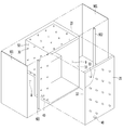
도 23 및 도 24는 진공단열체의 어느 일 꼭지점 부분을 보이는 사시도로서, 도 23은 도어힌지가 설치되기 전이고, 도 24는 도어힌지가 설치된 상태에서의 도면.
도 25와 도 26은 멀리언 부분에 제공되는 도어 힌지를 설명하는 도면이다. 도 24는 도어힌지가 설치된 모습이고, 도 25는 도어힌지가 설치되기 전 상태에서의 도면.
도 27은 멀리언 지지 프레임의 사시도.
도 28은 멀리언 안착 프레임의 작용을 설명하는 절개 사시도.
도 29는 도 28의 A부분을 확대한 단면도.
도 30은 도 28의 B부분을 확대한 단면도.
도 31은 다른 실시예에 따른 멀리언 안착 프레임을 설명하는 단면도.
도 32는 도 31의 D부분의 확대도이다.
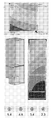
도 33은 보강 프레임을 위한 시뮬레이션 조건을 보이는 도면.
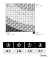
도 34 내지 도 38은 시뮬레이션의 결과를 설명하는 도면으로서, 도 34는 종래 폴리우레탄이 내부에 충전되는 냉장고에 대하여 시뮬레이션 한 결과이고, 도 35는 실시예에 따른 진공단열체가 적용되는 냉장고에서 상기 보강 프레임을 사용하지 않은 경우에 대하여 시뮬레이션 한 결과이고, 도 36은 실시예에 따른 진공단열체가 적용되는 냉장고에서 상기 보강 프레임 중에서 상기 내부 보강 프레임만을 사용하는 경우에 대하여 시뮬레이션 한 결과이고, 도 37은 실시예에 따른 진공단열체가 적용되는 냉장고에서 상기 보강 프레임 중에서 상기 외부 보강 프레임만을 사용하는 경우에 대하여 시뮬레이션 한 결과이고, 도 38은 실시예에 따른 진공단열체가 적용되는 냉장고에서 상기 보강 프레임 중에서 상기 외부 보강 프레임 및 상기 내부 보강 프레임을 모두 사용하는 경우에 대하여 시뮬레이션 한 결과를 보이는 도면.
도 39는 상기 보강 프레임의 두께를 1.25mm로 하는 때의 시뮬레이션의 결과를 보이는 도면.
도 40은 상기 보강 프레임의 두께를 1.2mm로 하는 때의 시뮬레이션의 결과를 보이는 도면.
도 41보강 프레임의 각 부재를 보이는 도면.
도 42는 일 실시형태에 따른 보강 프레임의 부재를 보이는 도면.
도 43은 다른 실시예에 따른 보강 프레임의 부재를 보이는 도면.
도 44와 도 45는 또 다른 실시형태에 따른 보강 프레임의 부재를 보이는 도면.
도 46과 도 47은 다른 실시형태에 따른 보강 프레임의 부재를 보이는 도면. 1 is a perspective view of a refrigerator according to an embodiment.
2 is a view schematically showing a vacuum insulator used in a body and a door of a refrigerator.
Figure 3 is a view showing various embodiments of the internal configuration of the vacuum space.
4 is a view showing various embodiments of a conductive resistance sheet and its periphery.
5 is a graph showing a change in adiabatic performance and a change in gas conductivity according to vacuum pressure by applying a simulation.
6 is a graph for observing the process of evacuating the interior of the vacuum insulator with time and pressure when a supporting unit is used.
7 is a graph comparing vacuum pressure and gas conductivity.
8 is a diagram modeling various load conditions given to an upright vacuum insulator.
9 to 11 are views for explaining the deformation of the vacuum insulator.
12 is an exploded perspective view of a refrigerator according to an embodiment.
13 is a partial cutaway cross-sectional view of a rear edge portion of a vacuum insulator.
14 is a cross-sectional view of a vacuum insulator illustrating a rear frame according to another embodiment.
15 is a cross-sectional view of a vacuum insulator illustrating a rear frame according to another embodiment.
16 is a cross-sectional view of a vacuum insulator illustrating a rear frame according to another embodiment.
17 is a view showing a heat exchange pipe line in a vacuum insulator with a reinforcement frame installed.
18 is an enlarged view of part A in FIG. 17;
19 is a sectional perspective view of a vacuum insulator explaining a reinforcement frame according to another embodiment.
20 is a perspective sectional view of a vacuum insulator explaining a reinforcement frame according to another embodiment.
21 is a cross-sectional view of a vacuum insulator explaining a reinforcement frame according to another embodiment.
22 is a cross-sectional view of a vacuum insulator explaining a reinforcement frame according to another embodiment.
23 and 24 are perspective views showing a part of a vertex of a vacuum insulator, FIG. 23 is before the door hinge is installed, and FIG. 24 is a view in which the door hinge is installed.
25 and 26 are views for explaining the door hinge provided in the mullion part. 24 is a state in which the door hinge is installed, and FIG. 25 is a view in a state before the door hinge is installed.
27 is a perspective view of a mullion support frame.
28 is a cutaway perspective view illustrating the operation of the mullion seating frame.
FIG. 29 is an enlarged sectional view of part A of FIG. 28;
30 is an enlarged sectional view of part B of FIG. 28;
31 is a cross-sectional view illustrating a mullion seating frame according to another embodiment.
32 is an enlarged view of a portion D of FIG. 31.
33 shows simulation conditions for a reinforcement frame.
34 to 38 are diagrams for explaining the results of the simulation. FIG. 34 is a simulation result of a refrigerator in which a conventional polyurethane is filled, and FIG. 35 is the reinforcement in a refrigerator to which a vacuum insulator according to an embodiment is applied. The simulation results for the case where the frame is not used, and FIG. 36 is the simulation result for the case where only the internal reinforcement frame is used among the reinforcement frames in the refrigerator to which the vacuum insulator according to the embodiment is applied, and FIG. 37 is implemented It is a result of simulating a case where only the external reinforcement frame is used among the reinforcing frames in a refrigerator to which a vacuum insulator according to an example is applied, and FIG. 38 shows the external reinforcement among the reinforcing frames in a refrigerator to which a vacuum insulator according to an embodiment is applied. A diagram showing the simulation results for the case where both the frame and the internal reinforcement frame are used.
39 is a view showing the results of a simulation when the thickness of the reinforcing frame is 1.25 mm.
40 is a view showing the results of a simulation when the thickness of the reinforcing frame is 1.2 mm.
Fig. 41 shows each member of the reinforcement frame.
42 shows a member of a reinforcement frame according to one embodiment.
43 is a view showing a member of a reinforcement frame according to another embodiment.
44 and 45 show a member of a reinforcing frame according to another embodiment.
46 and 47 show members of a reinforcing frame according to another embodiment.
이하에서는 도면을 참조하여 본 발명의 구체적인 실시예를 제안한다. 그러나, 본 발명의 사상이 이하에 제시되는 실시예에 제한되지는 아니하고, 본 발명의 사상을 이해하는 당업자는 동일한 사상의 범위 내에 포함되는 다른 실시예를 구성요소의 부가, 변경, 삭제, 및 추가 등에 의해서 용이하게 제안할 수 있을 것이나, 이 또한 본 발명 사상의 범위 내에 포함된다고 할 것이다. Hereinafter, with reference to the drawings, a specific embodiment of the present invention is proposed. However, the spirit of the present invention is not limited to the embodiments presented below, and those skilled in the art who understand the spirit of the present invention may add, change, delete, and add other embodiments that fall within the scope of the same spirit. It can be easily proposed by the like, but it will also be said to be included within the scope of the present invention.
이하에 실시예의 설명을 위하여 제시되는 도면은 실제 물품과는 다르거나 과장되거나 간단하거나 세밀한 부품은 간략하게 표시될 수 있으나, 이는 본 발명 기술사상 이해의 편리를 도모하기 위한 것으로서, 도면에 제시되는 크기와 구조와 형상으로 제한되어 해석되지 않아야 한다. 그러나, 가급적 실제의 모양을 나타내기 위하여 노력한다. The drawings presented for the description of the embodiments below may be different from actual products, exaggerated, simple or detailed parts may be briefly displayed, but this is for convenience of understanding the technical idea of the present invention, and the sizes presented in the drawings And should not be interpreted as limited to structure and shape. However, we try to show the actual shape as much as possible.
이하의 실시예는, 서로 충돌하지 않는다면, 어느 하나의 실시예의 설명이 다른 하나의 실시예의 설명에 적용될 수도 있고, 어느 하나의 실시예의 일부 구성이 다른 하나의 구성에 특정 부분만이 변형된 상태에서 적용될 수 있다.In the following embodiments, if they do not conflict with each other, the description of one embodiment may be applied to the description of another embodiment, and some of the configurations of one embodiment are modified with only a specific portion of the other configuration Can be applied.
이하의 설명에서 진공압은 대기압보다 낮은 그 어떤 압력상태를 의미한다. 그리고, A가 B보다 진공도가 높다는 표현은 A의 진공압이 B의 진공압보다 낮다는 것을 의미한다. In the following description, vacuum pressure means any pressure state lower than atmospheric pressure. And, the expression that A has a higher degree of vacuum than B means that the vacuum pressure of A is lower than that of B.
이하 실시예의 설명에서 우선하여 설치된다는 의미는 우선으로 설치되지 않은 부재는 제공되지 않는 경우도 본 발명 실시의 범위 내에 포함되는 것을 의미할 수 있다. In the following description of the embodiments, the meaning of preferential installation may mean that a member that is not preferentially installed is included within the scope of the present invention even when not provided.
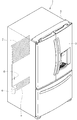
도 1은 실시예에 따른 냉장고의 사시도이다. 1 is a perspective view of a refrigerator according to an embodiment.
도 1을 참조하면, 냉장고(1)에는 저장물을 저장할 수 있는 캐비티(9)가 제공되는 본체(2)와, 상기 본체(2)를 개폐하도록 마련되는 도어(3)가 포함된다. 상기 도어(3)는 회동할 수 있게 배치되거나 슬라이드 이동이 가능하게 배치되어 캐비티(9)를 개폐할 수 있다. 상기 캐티비(9)는 냉장실 및 냉동실 중의 적어도 하나를 제공할 수 있다. Referring to FIG. 1, the
상기 캐비티에 냉기를 공급하는 냉동사이클을 이루는 부품이 마련된다. 상세하게는, 냉매를 압축하는 압축기(4)와, 압축된 냉매를 응축하는 응축기(5)와, 응축된 냉매를 팽창시키는 팽창기(6)와, 팽창된 냉매를 증발시켜 열을 빼앗는 증발기(7)가 포함된다. 전형적인 구조로서, 상기 증발기(7)가 인접하는 위치에 팬을 설치하고, 팬으로부터 송풍된 유체가 상기 증발기(7)를 통과한 다음에 캐비티(9)로 송풍되도록 할 수 있다. 상기 팬에 의한 송풍량 및 송풍방향을 조정하거나 순환 냉매의 양을 조절하거나 압축기의 압축률을 조정함으로써 냉동부하를 조절하여, 냉장공간 또는 냉동공간의 제어를 수행할 수 있다. A part constituting a refrigeration cycle for supplying cold air to the cavity is provided. In detail, the
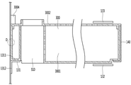
도 2는 냉장고의 본체 및 도어에 사용되는 진공단열체를 개략적으로 나타내는 도면으로서, 본체 측 진공단열체는 상면과 측면의 벽이 제거된 상태로 도시되고, 도어 측 진공단열체는 전면의 벽 일부가 제거된 상태의 도면이다. 또한, 전도저항쉬트(60)(63)가 제공되는 부분의 단면을 개략적으로 나타내어 이해가 편리하게 되도록 하였다. 2 is a view schematically showing a vacuum insulator used for the main body and a door of a refrigerator, and the main body side vacuum insulator is shown with the upper and side walls removed, and the door side vacuum insulator is a part of the front wall. Is the removed state. In addition, the cross-sections of the portions where the
도 2를 참조하면, 진공단열체에는, 저온공간의 벽을 제공하는 제 1 플레이트 부재(10)와, 고온공간의 벽을 제공하는 제 2 플레이트 부재(20)와, 상기 제 1 플레이트 부재(10)와 상기 제 2 플레이트 부재(20)의 사이 간격부로 정의되는 진공공간부(50)가 포함된다. 상기 제 1, 2 플레이트 부재(10)(20) 간의 열전도를 막는 전도저항쉬트(60)(63)가 포함된다. 상기 진공공간부(50)를 밀폐상태로 하기 위하여 상기 제 1 플레이트 부재(10)와 상기 제 2 플레이트 부재(20)를 밀봉하는 밀봉부(61)가 제공된다. 냉장고 또는 온장고에 상기 진공단열체가 적용되는 경우에는, 상기 제 1 플레이트 부재(10)는 이너케이스라고 할 수 있고, 상기 제 2 플레이트 부재(20)는 아웃케이스라고 할 수 있다. 본체 측 진공단열체의 하측 후방에는 냉동사이클을 제공하는 부품이 수납되는 기계실(8)이 놓이고, 상기 진공단열체의 어느 일측에는 진공공간부(50)의 공기를 배기하여 진공상태를 조성하기 위한 배기포트(40)가 제공된다. 또한, 제상수 및 전기선로의 설치를 위하여 진공공간부(50)를 관통하는 관로(64)가 더 설치될 수 있다. Referring to FIG. 2, the vacuum insulator includes a
상기 제 1 플레이트 부재(10)는, 제 1 플레이트 부재 측에 제공되는 제 1 공간을 위한 벽의 적어도 일부를 정의할 수 있다. 상기 제 2 플레이트 부재(20)는, 제 2 플레이트 부재 측에 제공되는 제 2 공간을 위한 벽의 적어도 일부를 정의할 수 있다. 상기 제 1 공간과 상기 제 2 공간은 온도가 서로 다른 공간으로 정의할 수 있다. 여기서, 각 공간의 위한 벽은, 공간에 직접 접하는 벽으로서의 기능을 수행하는 경우뿐만 아니라, 공간에 접하지 않는 벽으로서의 기능을 수행할 수도 있다. 예를 들어 각 공간에 접하는 별도의 벽을 더 가지는 물품의 경우에도 실시예의 진공단열체가 적용될 수 있는 것이다. The
상기 진공단열체가 단열효과의 손실을 일으키는 요인은, 제 1 플레이트 부재(10)와 제 2 플레이트 부재(20) 간의 열전도와, 제 1 플레이트 부재(10)와 제 2 플레이트 부재(20) 간의 열복사, 및 진공공간부(50)의 가스전도(gas conduction)가 있다. The factors that cause the vacuum insulator to cause a loss of heat insulation effect include heat conduction between the
이하에서는 상기 열전달의 요인과 관련하여 단열손실을 줄이기 위하여 제공되는 열저항유닛에 대하여 설명한다. 한편, 실시예의 진공단열체 및 냉장고는 진공단열체의 적어도 어느 한쪽에 또 다른 단열수단을 더 가지는 것을 배제하지 않는다. 따라서, 다른 쪽 일면에 발포 등을 이용하는 단열수단을 더 가질 수도 있다.Hereinafter, a heat resistance unit provided to reduce heat insulation loss in relation to the heat transfer factor will be described. On the other hand, the vacuum insulation body and the refrigerator of the embodiment are not excluded from further having another heat insulating means on at least one side of the vacuum insulation body. Therefore, it is possible to further have an insulating means using foam or the like on the other side.
도 3은 진공공간부의 내부구성에 대한 다양한 실시예를 보이는 도면이다. 3 is a view showing various embodiments of the internal configuration of the vacuum space.
먼저 도 3a를 참조하면, 상기 진공공간부(50)는 상기 제 1 공간 및 상기 제 2 공간과는 다른 압력, 바람직하게는 진공 상태의 제 3 공간으로 제공되어 단열손실을 줄일 수 있다. 상기 제 3 공간은 상기 제 1 공간의 온도 및 상기 제 2 공간의 온도의 사이에 해당하는 온도로 제공될 수 있다. 상기 제 3 공간은 진공 상태의 공간으로 제공되기 때문에, 상기 제 1 플레이트 부재(10) 및 상기 제 2 플레이트 부재(20)는 각 공간의 압력차만큼의 힘에 의해서 서로 접근하는 방향으로 수축하는 힘을 받기 때문에 상기 진공공간부(50)는 작아지는 방향으로 변형될 수 있다. 이 경우에는 진공공간부의 수축에 따른 복사전달량의 증가, 상기 플레이트 부재(10)(20)의 접촉에 따른 전도전달량의 증가에 따른 단열손실을 야기할 수 있다. Referring first to FIG. 3A, the
상기 진공공간부(50)의 변형을 줄이기 위하여 서포팅유닛(30)이 제공될 수 있다. 상기 서포팅유닛(30)에는 바(31)가 포함된다. 상기 바(31)는 제 1 플레이트 부재와 제 2 플레이트 부재의 사이 간격을 지지하기 위하여 상기 플레이트 부재에 대하여 실질적으로 수직한 방향으로 연장될 수 있다. 상기 바(31)의 적어도 어느 일단에는 지지 플레이트(35)가 추가로 제공될 수 있다. 상기 지지 플레이트(35)는 적어도 두 개 이상의 바(31)를 연결하고, 상기 제 1, 2 플레이트 부재(10)(20)에 대하여 수평한 방향으로 연장될 수 있다. 상기 지지 플레이트는 판상으로 제공될 수 있고, 격자형태로 제공되어 상기 제 1, 2 플레이트 부재(10)(20)와 접하는 면적이 작아져서 열전달이 줄어들도록 할 수 있다. 상기 바(31)와 상기 지지 플레이트는 적어도 일 부분에서 고정되어, 상기 제 1, 2 플레이트 부재(10)(20)의 사이에 함께 삽입될 수 있다. 상기 지지 플레이트(35)는 상기 제 1, 2 플레이트 부재(10)(20) 중 적어도 하나에 접촉하여 상기 제 1, 2 플레이트 부재(10)(20)의 변형을 방지할 수 있다. 또한, 상기 바(31)의 연장방향을 기준으로 할 때, 상기 지지플레이트(35)의 총단면적은 상기 바(31)의 총단면적보다 크게 제공하여, 상기 바(31)를 통하여 전달되는 열이 상기 지지 플레이트(35)를 통하여 확산될 수 있다. A supporting
상기 서포팅유닛(30)의 재질로는, 높은 압축강도, 낮은 아웃게싱(outgassing) 및 물흡수율, 낮은 열전도율, 고온에서 높은 압축강도, 및 우수한 가공성을 얻기 위하여, PC, glass fiber PC, low outgassing PC, PPS, 및 LCP 중에서 선택되는 수지를 사용할 수 있다. As a material of the supporting
상기 진공공간부(50)를 통한 상기 제 1, 2 플레이트 부재(10)(20) 간의 열복사를 줄이는 복사저항쉬트(32)에 대하여 설명한다. 상기 제 1, 2 플레이트 부재(10)(20)는 부식방지과 충분한 강도를 제공할 수 있는 스테인레스 재질로 제공될 수 있다. 상기 스테인레스 재질은 방사율이 0.16으로서 비교적 높기 때문에 많은 복사열 전달이 일어날 수 있다. 또한, 수지를 재질로 하는 상기 서포팅유닛의 방사율은 상기 플레이트 부재에 비하여 낮고 제 1, 2 플레이트 부재(10)(20)의 내면에 전체적으로 마련되지 않기 때문에 복사열에 큰 영향을 미치지 못한다. 따라서 상기 복사저항쉬트는 제 1 플레이트 부재(10)와 제 2 플레이트 부재(20) 간의 복사열 전달의 저감에 중점적으로 작용하기 위하여, 상기 진공공간부(50)의 면적의 대부분을 가로질러서 판상으로 제공될 수 있다. 상기 복사저항쉬트(32)의 재질로는, 방사율(emissivity)이 낮은 물품이 바람직하고, 실시예에서는 방사율 0.02의 알루미늄 박판이 바람직하게 사용될 수 있다. 또한, 한 장의 복사저항쉬트로는 충분한 복사열 차단작용을 얻을 수 없기 때문에, 적어도 두 장의 복사저항쉬트(32)가 서로 접촉하지 않도록 일정 간격을 두고 제공될 수 있다. 또한, 적어도 어느 한 장의 복사저항쉬트는 제 1, 2 플레이트 부재(10)(20)의 내면에 접하는 상태로 제공될 수 있다. A description will be given of a
도 3b를 참조하면, 서포팅유닛(30)에 의해서 플레이트 부재 간의 간격을 유지하고, 진공공간부(50)의 내부에 다공성물질(33)을 충전할 수 있다. 상기 다공성물질(33)은 제 1, 2 플레이트 부재(10)(20)의 재질인 스테인레스보다는 방사율이 높을 수 있지만, 진공공간부를 충전하고 있으므로 복사열전달의 저항효율이 높다. Referring to FIG. 3B, the spacing between the plate members is maintained by the supporting
본 실시예의 경우에는, 복사저항쉬트(32)가 없이도 진공단열체를 제작할 수 있는 효과가 있다. In the case of this embodiment, there is an effect capable of manufacturing a vacuum insulator without the
도 3c를 참조하면, 진공공간부(50)를 유지하는 서포팅유닛(30)이 제공되지 않는다. 이를 대신하여 다공성물질(33)이 필름(34)에 싸인 상태로 제공되었다. 이때 다공성물질(33)은 진공공간부의 간격을 유지할 수 있도록 압축된 상태로 제공될 수 있다. 상기 필름(34)은 예시적으로 PE재질로서 구멍이 뚫려있는 상태로 제공될 수 있다. Referring to Figure 3c, the supporting
본 실시예의 경우에는, 상기 서포팅유닛(30)이 없이 진공단열체를 제작할 수 있다. 다시 말하면, 상기 다공성물질(33)은 상기 복사저항쉬트(32)의 기능과 상기 서포팅유닛(30)의 기능을 함께 수행할 수 있다. In the case of this embodiment, the vacuum insulator can be produced without the supporting
도 4는 전도저항쉬트 및 그 주변부의 다양한 실시예를 보이는 도면이다. 도 2에는 각 전도저항쉬트가 구조가 간단하게 도시되어 있으나, 본 도면을 통하여 더 상세하게 이해될 수 있을 것이다. 4 is a view showing various embodiments of the conductive resistance sheet and its periphery. Although the structure of each conductive resistance sheet is simply illustrated in FIG. 2, it will be understood in more detail through the drawings.
먼저, 도 4a에 제시되는 전도저항쉬트는 본체 측 진공단열체에 바람직하게 적용될 수 있다. 상세하게, 상기 진공단열체의 내부를 진공으로 유지하기 위하여 상기 제 2 플레이트 부재(20)와 상기 제 1 플레이트 부재(10)는 밀봉되어야 한다. 이때 두 플레이트 부재는 각각이 온도가 서로 다르므로 양자 간에 열전달이 발생할 수 있다. 종류가 다른 두 플레이트 부재 간의 열전도를 방지하기 위하여 전도저항쉬트(60)가 마련된다. First, the conductive resistance sheet shown in FIG. 4A can be preferably applied to a vacuum insulator on the body side. In detail, the
상기 전도저항쉬트(60)는 상기 제 3 공간을 위한 벽의 적어도 일부를 정의하고 진공상태를 유지하도록 그 양단이 밀봉되는 밀봉부(61)로 제공될 수 있다. 상기 전도저항쉬트(60)는 상기 제 3 공간의 벽을 따라서 흐르는 열전도량을 줄이기 위하여 마이크로미터 단위의 얇은 박판으로 제공된다. 상기 밀봉부(610)는 용접부로 제공될 수 있다. 즉, 전도저항쉬트(60)와 플레이트 부재(10)(20)가 서로 융착되도록 할 수 있다. 서로 간의 융착 작용을 이끌어내기 위하여 상기 전도저항쉬트(60)와 플레이트 부재(10)(20)는 서로 같은 재질을 사용할 수 있고, 스테인레스를 그 재질로 할 수 있다. 상기 밀봉부(610)는 용접부로 제한되지 않고 코킹 등의 방법을 통하여 제공될 수도 있다. 상기 전도저항쉬트(60)는 곡선 형상으로 제공될 수 있다. 따라서, 상기 전도저항쉬트(60)의 열전도의 거리는 각 플레이트 부재의 직선거리보다 길게 제공되어, 열전도량은 더욱 줄어들 수 있다. The
상기 전도저항쉬트(60)를 따라서 온도변화가 일어난다. 따라서, 그 외부와의 열전달을 차단하기 위하여, 상기 전도저항쉬트(60)의 외부에는 차폐부(62)가 제공되어 단열작용이 일어나도록 하는 것이 바람직하다. 다시 말하면, 냉장고의 경우에 제 2 플레이트 부재(20)는 고온이고 제 1 플레이트 부재(10)는 저온이다. 그리고, 상기 전도저항쉬트(60)는 고온에서 저온으로 열전도가 일어나고 열흐름을 따라서 쉬트의 온도가 급격하게 변한다. 그러므로, 상기 전도저항쉬트(60)가 외부에 대하여 개방되는 경우에는 개방된 곳을 통한 열전달이 심하게 발생할 수 있다. 이러한 열손실을 줄이기 위하여 상기 전도저항쉬트(60)의 외부에는 차폐부(62)가 제공되도록 한다. 예를 들어, 상기 전도저항쉬트(60)가 저온공간 또는 고온공간의 어느 쪽에 노출되는 경우에도, 상기 전도저항쉬트(60)는 노출되는 양만큼 전도저항의 역할을 수행하지 못하기 때문에 바람직하지 않게 된다. A temperature change occurs along the
상기 차폐부(62)는 상기 전도저항쉬트(60)의 외면에 접하는 다공성물질로 제공될 수도 있고, 상기 전도저항쉬트(60)의 외부에 놓이는 별도의 가스켓으로 예시가능한 단열구조물로 제공될 수도 있고, 본체 측 진공단열체가 도어 측 진공단열체에 대하여 닫힐 때 대응하는 전도저항쉬트(60)와 마주보는 위치에 제공되는 진공단열체의 일 부분으로 제공될 수도 있다. 상기 본체와 상기 도어가 개방되었을 때에도 열손실을 줄이기 위하여, 상기 차폐부(62)는 다공성물질 또는 별도의 단열구조물로 제공되는 것이 바람직할 것이다. The
상기 가스켓은 상기 전도저항쉬트의 차폐부의 기능이 수행될 수도 있지만, 상기 도어와 상기 본체의 사이에 제공되어, 도어와 본체의 접하는 부분에 대한 실링작용을 수행할 수 있다. 상기 가스켓은 도어 또는 본체에 제공될 수 있다. Although the gasket may function as a shield of the conductive resistance sheet, it may be provided between the door and the main body to perform a sealing action on the contact portion between the door and the main body. The gasket may be provided on the door or the body.
도 4b에 제시되는 전도저항쉬트는 도어 측 진공단열체에 바람직하게 적용될 수 있고, 도 4a에 대하여 달라지는 부분을 상세하게 설명하고, 동일한 부분은 동일한 설명이 적용되는 것으로 한다. 상기 전도저항쉬트(60)의 바깥쪽으로는 사이드 프레임(70)이 더 제공된다. 상기 사이드 프레임(70)은 도어와 본체와의 실링을 위한 부품과 배기공정에 필요한 배기포트와 진공유지를 위한 게터포트 등이 놓일 수 있다. 이는 본체 측 진공단열체의 경우에는 부품의 장착이 편리할 수 있지만, 도어측은 위치가 제한되기 때문이다. The conduction resistance sheet shown in FIG. 4B can be preferably applied to a door-side vacuum insulator, and the different parts will be described in detail with respect to FIG. 4A, and the same parts will be applied to the same description. A
도어 측 진공단열체의 경우에는 상기 전도저항쉬트(60)는 진공공간부의 선단부, 즉 모서리 측면부에 놓이기 어렵다. 이는 도어(3)의 모서리 에지부는 본체와 달리 외부로 드러나기 때문이다. 더 상세하게 상기 전도저항쉬트(60)가 진공공간부의 선단부에 놓이면, 상기 도어(3)의 모서리 에지부는 외부로 드러나기 때문에, 상기 전도저항쉬트(60)의 단열을 위하여 별도의 단열부를 구성해야 하는 불리함이 있기 때문이다. In the case of a door-side vacuum insulator, the
도 4c에 제시되는 전도저항쉬트는 진공공간부를 관통하는 관로에 바람직하게 설치될 수 있고, 도 4a 및 도 4b에 대하여 달라지는 부분을 상세하게 설명하고, 동일한 부분은 동일한 설명이 적용되는 것으로 한다. 관로(64)가 제공되는 주변부에는 도 4a와 동일한 형상으로 제공될 수 있고, 더 바람직하게는 주름형 전도저항쉬트(63)가 제공될 수 있다. 이에 따르면 열전달경로를 길게 할 수 있고, 압력차에 의한 변형을 방지할 수 있다. 또한 전도저항쉬트의 단열을 위한 별도의 차폐부재도 제공될 수 있다.The conduction resistance sheet shown in FIG. 4C can be preferably installed in a pipeline passing through the vacuum space part, and the different parts with respect to FIGS. 4A and 4B will be described in detail, and the same parts will be applied to the same description. A peripheral portion where the
다시 도 4a를 참조하여 제 1 플레이트 부재(10)와 제 2 플레이트 부재(20) 간의 열전달경로를 설명한다. 진공단열체를 통과하는 열에는, 상기 진공단열체의 표면, 더 상세하게 상기 전도저항쉬트(60)를 따라서 전달되는 표면전도열(①)과, 상기 진공단열체의 내부에 제공되는 서포팅유닛(30)을 따라서 전도되는 서포터전도열(②)과, 진공공간부의 내부 가스를 통한 가스전도열(③)과, 진공공간부를 통하여 전달되는 복사전달열(④)로 구분할 수 있다. Referring to FIG. 4A again, a heat transfer path between the
상기 전달열은 다양한 설계 수치에 따라서 변형될 수 있다. 예를 들어 제 1, 2 플레이트 부재(10)(20)가 변형되지 않고 진공압에 견딜 수 있도록 서포팅유닛을 변경할 수도 있고, 진공압을 변경할 수 있고, 플레이트 부재의 간격길이를 달리할 수 있고, 전도저항유닛의 길이를 변경할 수 있고, 플레이트 부재가 제공하는 각 공간(제 1 공간 및 제 2 공간)의 온도차를 어느 정도를 하는지에 따라서 달라질 수 있다. 실시예의 경우에는 총열전달량이 종래 폴리우레탄을 발포하여 제공되는 단열구조물에 비하여 열전달량이 작아지도록 하는 것을 고려할 때 바람직한 구성을 알아내었다. 여기서, 종래 폴리우레탄을 발포하는 냉장고에서의 실질열전달계수는 19.6mW/mK으로 제시될 수 있다. The heat of transfer may be modified according to various design values. For example, the supporting units can be changed so that the first and
이에 따른 실시예의 진공단열체의 열전달량을 상대적으로 분석하면, 가스전도열(③)에 의한 열전달이 가장 작아지게 할 수 있다. 예를 들어 전체 열전달의 4%이하로 이를 제어할 수 있다. 상기 표면전도열(①) 및 상기 서포터전도열(②)의 합으로 정의되는 고체전도열에 의한 열전달이 가장 많다. 예를 들어 75%에 달할 수 있다. 상기 복사전달열(③)은 상기 고체전도열에 비해서는 작지만 가스전도열에 의한 열전달보다는 크게 된다. 예를 들어, 상기 복사전달열(③)은 전체 열전달량의 대략 20%를 차지할 수 있다.Accordingly, when the heat transfer amount of the vacuum insulator of the embodiment is relatively analyzed, the heat transfer by the gas conduction heat (③) can be made the smallest. For example, it can be controlled to 4% or less of the total heat transfer. The heat transfer by the solid conductive heat defined by the sum of the surface conductive heat (①) and the supporter conductive heat (②) is the most. For example, it can reach 75%. The radiant heat (③) is smaller than the solid heat, but is larger than the heat by gas heat. For example, the radiation heat (③) may occupy approximately 20% of the total heat transfer amount.
이러한 열전달분포에 따르면, 실질열전달계수(eK: effective K)(W/mK)는 상기 전달열(①②③④)을 비교할 때 수학식 1의 순서를 가질 수 있다. According to this heat transfer distribution, the effective heat transfer coefficient (eK: effective K) (W/mK) may have the order of
![]()
![]()
여기서 상기 실질열전달계수(eK)는 대상 물품의 형상과 온도차를 이용하여 측정할 수 있는 값으로서, 전체 열전달량과 열전달되는 적어도 하나의 부분의 온도를 측정하여 얻어낼 수 있는 값이다. 예를 들어 냉장고 내에 정량적으로 측정이 가능한 가열원을 두고서 발열량을 알고(W), 냉장고의 도어 본체와 도어의 테두리를 통하여 각각 전달되는 열을 도어의 온도분포를 측정하고(K), 열이 전달되는 경로를 환산값으로 확인함으로써(m), 실질열전달계수를 구할 수 있는 것이다. Here, the real heat transfer coefficient (eK) is a value that can be measured using the shape and temperature difference of the target article, and is a value that can be obtained by measuring the total heat transfer amount and the temperature of at least one portion that is heat transferred. For example, a heating source that can be quantitatively measured in a refrigerator is used to know the amount of heat generated (W), and the temperature distribution of the door is measured by measuring the temperature distribution of the door (K), and the heat transmitted through the door body of the refrigerator and the rim of the door (K). The actual heat transfer coefficient can be obtained by confirming the path to be converted (m).
전체 진공단열체의 상기 실질열전달계수(eK)는 k=QL/A△T로 주어지는 값으로서, Q는 열전달량(W)으로서 히터의 발열량을 이용하여 획득할 수 있고, A는 진공단열체의 단면적(m2)이고, L은 진공단열체의 두께(m)이고, △T는 온도차로서 정의할 수 있다. The real heat transfer coefficient (eK) of the entire vacuum insulation body is a value given by k=QL/AΔT, Q is the heat transfer amount (W), and can be obtained by using the heating value of the heater, and A is the vacuum insulation body. The cross-sectional area (m 2 ), L is the thickness of the vacuum insulator (m), and ΔT can be defined as the temperature difference.
상기 표면전도열은, 전도저항쉬트(60)(63)의 입출구의 온도차(△T), 전도저항쉬트의 단면적(A), 전도저항쉬트의 길이(L), 전도저항쉬트의 열전도율(k)(전도저항쉬트의 열전도율은 재질의 물성치로서 미리 알아낼 수 있다)를 통하여 전도열량을 알아낼 수 있다. 상기 서포터전도열은, 서포팅유닛(30)의 입출구의 온도차(△T), 서포팅유닛의 단면적(A), 서포팅유닛의 길이(L), 서포팅유닛의 열전도율(k)을 통하여 전도열량을 알아낼 수 있다. 여기서, 상기 서포팅유닛의 열전도율은 재질의 물성치로서 미리 알아낼 수 있다. 상기 가스전도열(③)과 상기 복사전달열(④)의 합은 상기 전체 진공단열체의 열전달량에서 상기 표면전도열과 상기 서포터전도열을 빼는 것에 의해서 알아낼 수 있다. 상기 가스 전도열과 상기 복사전달열의 비율은 진공공간부의 진공도를 현저히 낮추어 가스 전도열이 없도록 하였을 때의 복사전달열을 구하는 것으로서 알아낼 수 있다. The surface conduction heat, the temperature difference (ΔT) of the inlet and outlet of the
상기 진공공간부(50)의 내부에 다공성물질이 제공되는 경우에, 다공성물질전도열(⑤)은 상기 서포터전도열(②)과 복사열(④)을 합한 양으로 고려할 수 있다. 상기 다공성물질전도열은 다공성물질의 종류와 양 등의 다양한 변수에 의해서 변경될 수 있다.When a porous material is provided inside the
실시예에 따르면, 서로 인접하는 바(31)가 이루는 기하학적 중심과 바가 위치하는 곳과의 온도차(△T1)는 0.5도씨 미만으로 제공되는 것이 바람직하다. 또한, 인접하는 바가 이루는 기하학적 중심과 진공단열체의 에지부와의 온도차(△T2)는 5도씨 미만으로 제공되는 것을 바람직하게 제안할 수 있다. 또한, 상기 제 2 플레이트 부재에 있어서, 상기 전도저항쉬트(60)(63)를 통과하는 열전달 경로가 제 2 플레이트 부재와 만나는 지점에서, 제 2 플레이트 부재의 평균온도와의 온도차이가 가장 클 수 있다. 예를 들어, 상기 제 2 공간이 상기 제 1 공간에 비하여 뜨거운 영역인 경우에는, 상기 전도저항쉬트를 통과하는 열전달 경로가 제 2 플레이트 부재와 만나는 제 2 플레이트 부재의 지점에서 온도가 최저가 된다. 마찬가지로, 상기 제 2 공간이 상기 제 1 공간에 비하여 차가운 영역인 경우에는, 상기 전도저항쉬트를 통과하는 열전달 경로가 제 2 플레이트 부재와 만나는 제 2 플레이트 부재의 지점에서 온도가 최고가 된다. According to the embodiment, it is preferable that the temperature difference (ΔT 1 ) between the geometric center formed by the
이는 전도저항쉬트를 통과하는 표면전도열을 제외하는 다른 곳을 통한 열전달량은 충분히 제어되어야 하고, 표면전도열이 가장 큰 열전달량을 차지하는 경우에 비로소 전체적으로 진공단열체가 만족하는 전체 열전달량을 달성할 수 있는 이점을 얻는 것을 의미한다. 이를 위하여 상기 전도저항쉬트의 온도변화량은 상기 플레이트 부재의 온도변화량보다 크게 제어될 수 있다. This means that the amount of heat transfer through a place other than the surface conduction heat passing through the conduction resistance sheet must be sufficiently controlled, and only when the surface conduction heat occupies the largest amount of heat transfer can achieve the total amount of heat transfer that the vacuum insulator satisfies as a whole. It means getting an advantage. To this end, the temperature change amount of the conductive resistance sheet can be controlled to be larger than the temperature change amount of the plate member.
상기 진공단열체를 제공하는 각 부품의 물리적 특징에 대하여 설명한다. 상기 진공단열체는 진공압에 의한 힘이 모든 부품에 가하여진다. 따라서, 일정한 수준이 강도(strength)(N/m2)를 가지는 재료가 사용되는 것이 바람직하다. The physical characteristics of each component providing the vacuum insulator will be described. In the vacuum insulator, a force by vacuum pressure is applied to all parts. Therefore, it is preferable that a material having a certain level of strength (N/m 2 ) is used.
이러한 배경하에서, 상기 플레이트 부재(10)(20)와 상기 사이드 프레임(70)은 진공압에도 불구하고 파손되지 않는 충분한 강도(strength)가 있는 재질로 제공되는 것이 바람직하다. 예를 들어 서포터전도열을 제한하기 위하여 바(31)의 개수를 작게 하는 경우에는 진공압에 의한 플레이트 부재의 변형이 발생하여 외관이 좋지 않은 영향을 줄 수 있다. 상기 복사저항쉬트(32)는 방사율이 낮으면서 용이하게 박막가공이 가능한 물품이 바람직하고, 외부충격에 변형되지 않은 정도의 강도가 확보되어야 한다. 상기 서포팅유닛(30)은 진공압에 의한 힘을 지지하고 외부충격에 견딜 수 있는 강도로 제공되고 가공성이 있어야 한다. 상기 전도저항쉬트(60)는 얇은 판상이면서도 진공압을 견딜 수 있는 재질이 사용되는 것이 바람직하다. Under this background, it is preferable that the
실시예에서는 상기 플레이트 부재, 사이드 프레임, 및 전도저항쉬트는 동일한 강도인 스테인레스 재질을 사용할 수 있다. 상기 복사저항쉬트는 스테인레스보다는 약한 강도인 알루미늄을 사용할 수 있다. 상기 서포팅유닛은 알루미늄보다 약한 강도인 수지를 그 재질로 사용할 수 있다. In an embodiment, the plate member, the side frame, and the conductive resistance sheet may use stainless steel having the same strength. As the radiation resistance sheet, aluminum having a weaker strength than stainless steel may be used. The supporting unit may use a resin having a weaker strength than aluminum as its material.
상기되는 바와 같은 재질의 측면에서 바라본 강도와 달리, 강성 측면에서의 분석이 요청된다. 상기 강성(stiffness)(N/m)은 쉽게 변형되지 않는 성질로서 동일한 재질을 사용하더라도 그 형상에 따라서 강성이 달라질 수 있다. 상기 전도저항쉬트(60)(63)는 강도가 있는 재질을 사용할 수 있으나, 열저항을 높이고 진공압이 가하여질 때 거친면이 없이 고르게 펼쳐져 방사열을 최소화하기 위하여 강성이 낮은 것이 바람직하다. 상기 복사저항쉬트(32)는 변형으로 다른 부품에 닿지 않도록 하기 위하여 일정 수준의 강성이 요청된다. 특히, 상기 복사저항쉬트의 테두리 부분은 자중에 따른 처짐이 발생하여 전도열을 발생시킬 수 있다. 그러므로, 일정 수준의 강성이 요청된다. 상기 서포팅유닛(30)은 플레이트 부재로부터의 압축응력 및 외부충격에 견딜 수 있는 정도의 강성이 요청된다. Unlike the strength seen in terms of the material as described above, analysis in terms of stiffness is required. The stiffness (N/m) is a property that is not easily deformed, and even if the same material is used, the stiffness may vary depending on its shape. The
실시예에서는 상기 플레이트 부재, 및 사이드 프레임은 진공압에 의한 변형을 방지하도록 가장 강성이 높은 것이 바람직하다. 상기 서포팅유닛, 특히 바는 두번째로 큰 강성을 가지는 것이 바람직하다. 상기 복사저항쉬트는 서포팅유닛보다는 약하지만 전도저항쉬트보다는 강성을 가지는 것이 바람직하다. 마지막으로 상기 전도저항쉬트는 진공압에 의한 변형이 용이하게 일어나는 것이 바람직하여 가장 강성이 낮은 재질을 사용하는 것이 바람직하다. In the embodiment, the plate member and the side frame are preferably the most rigid to prevent deformation by vacuum pressure. It is preferable that the supporting unit, especially the bar, has the second largest rigidity. The radiation resistance sheet is weaker than the supporting unit, but it is preferable to have stiffness than the conduction resistance sheet. Lastly, the conductive resistance sheet is preferably easily deformed by vacuum pressure, so it is preferable to use a material having the lowest rigidity.
상기 진공공간부(50) 내부를 다공성물질(33)로 채우는 경우에도 전도저항쉬트가 가장 강성이 낮도록 하는 것이 바람직하고, 플레이트 부재 및 사이드 프레임이 가장 큰 강성을 가지는 것이 바람직하다. Even when the inside of the
이하에서는 진공단열체의 내부 상태에 따라서 바람직하게 제시되는 진공압을 설명한다. 이미 설명된 바와 같이 상기 진공단열체의 내부는 열전달을 줄일 수 있도록 진공압을 유지해야 한다. 이때에는 가급적 낮은 진공압을 유지하는 것이 열전달의 저감을 위해서 바람직한 것은 용이하게 예상할 수 있을 것이다. Hereinafter, a vacuum pressure that is preferably presented according to the internal state of the vacuum insulator will be described. As already described, the inside of the vacuum insulator must maintain a vacuum pressure to reduce heat transfer. At this time, it is easily predictable that it is desirable to maintain a vacuum pressure as low as possible for reducing heat transfer.
상기 진공공간부는, 서포팅유닛(30)에 의해서만 열전달에 저항할 수도 있고, 진공공간부(50)의 내부에 서포팅유닛과 함께 다공성물질(33)이 충전되어 열전달에 저항할 수도 있고, 서포팅유닛은 적용하지 않고 다공성물질로 열전달에 저항할 수도 있다. The vacuum space portion may resist heat transfer only by the supporting
서포팅유닛만이 제공되는 경우에 대하여 설명한다. A case will be described in which only the supporting unit is provided.
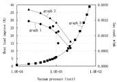
도 5는 시뮬레이션을 적용하여 진공압에 따른 단열성능의 변화와 가스전도도의 변화를 나타내는 그래프이다. 5 is a graph showing a change in adiabatic performance and a change in gas conductivity according to vacuum pressure by applying a simulation.
도 5를 참조하면, 진공압이 낮아질수록 즉, 진공도가 높아질수록 본체만의 경우(그래프 1) 또는 본체와 도어를 합한 경우(그래프 2)의 열부하는, 종래의 폴리우레탄을 발포한 물품과 비교하여 열부하(heat load)가 줄어들어서 단열성능이 향상되는 것을 볼 수 있다. 그러나, 단열성능이 향상되는 정도는 점진적으로 낮아지는 것을 볼 수 있다. 또한, 진공압이 낮아질수록 가스전도도(그래프 3)가 낮아지는 것을 볼 수 있다. 그러나, 진공압이 낮아지더라도 단열성능 및 가스전도도가 개선되는 비율은 점진적으로 낮아지는 것을 알 수 있다. 따라서, 가급적 진공압을 낮추는 것이 바람직하지만, 과도한 진공압을 얻기 위해서는 시간이 많이 들고, 과도한 게터(getter)사용으로 비용이 많이 드는 문제점이 있다. 실시예에서는 상기 관점에서 최적의 진공압을 제안한다. Referring to FIG. 5, the lower the vacuum pressure, that is, the higher the degree of vacuum, the heat load in the case of the body only (Graph 1) or when the body and the door are combined (Graph 2), compared with a conventional polyurethane foamed article. As a result, it can be seen that the heat load is reduced to improve the heat insulation performance. However, it can be seen that the degree of improvement in the thermal insulation performance gradually decreases. In addition, it can be seen that the lower the vacuum pressure, the lower the gas conductivity (Graph 3). However, it can be seen that even when the vacuum pressure is lowered, the rate at which the insulation performance and gas conductivity are improved gradually decreases. Therefore, it is desirable to lower the vacuum pressure as much as possible, but it takes a long time to obtain an excessive vacuum pressure, and there is a problem in that it is expensive due to excessive use of a getter. The embodiment proposes an optimal vacuum pressure from the above point of view.
도 6은 서포팅유닛이 사용되는 경우에 진공단열체의 내부를 배기하는 공정을 시간과 압력으로 관찰하는 그래프이다. 6 is a graph for observing the process of evacuating the interior of the vacuum insulator with time and pressure when a supporting unit is used.
도 6을 참조하면, 상기 진공공간부(50)를 진공상태로 조성하기 위하여, 가열하면서(baking) 진공공간부의 부품에 남아있는 잠재적인 기체를 기화시키면서 진공펌프로 진공공간부의 기체를 배기한다. 그러나, 일정 수준 이상의 진공압에 이르면 더 이상 진공압의 수준이 높아지지 않는 지점에 이르게 된다(△t1). 이후에는 진공펌프의 진공공간부의 연결을 끊고 열을 가하여 게터를 활성화시킨다(△t2). 게터가 활성화되면 일정 시간 동안은 진공공간부의 압력이 떨어지지만 정상화되어 일정 수준의 진공압을 유지한다. 게터 활성화 이후에 일정수준의 진공압을 유지할 때의 진공압은 대략 1.8×10⁻⁶Torr이다. Referring to FIG. 6, in order to compose the
실시예에서는 진공펌프를 동작시켜 기체를 배기하더라도 더이상 실질적으로 진공압이 낮아지지 않는 지점을 상기 진공단열체에서 사용하는 진공압의 하한으로 설정하여 진공공간부의 최저 내부 압력을 1.8×10⁻⁶Torr로 설정한다. In the embodiment, even if the gas is exhausted by operating the vacuum pump, the point at which the vacuum pressure is no longer substantially lowered is set as the lower limit of the vacuum pressure used in the vacuum insulator to set the minimum internal pressure of the vacuum space portion to 1.8×10 -6 Torr. Set to
도 7은 진공압과 가스전도도(gas conductivity)를 비교하는 그래프이다. 7 is a graph comparing vacuum pressure and gas conductivity.
도 7을 참조하면, 상기 진공공간부(50) 내부의 사이 갭의 크기에 따라서 진공압에 따른 가스전도열(gas conductivity)을 실질열전달계수(eK)의 그래프로 나타내었다. 상기 진공공간부의 갭은 2.76mm, 6.5mm, 및 12.5mm의 세 가지 경우로 측정하였다. 상기 진공공간부의 갭은 다음과 같이 정의된다. 상기 진공공간부의 내부에 상기 복사저항쉬트(32)가 있는 경우는 상기 복사저항쉬트와 인접한 플레이트 사이의 거리이고, 상기 진공공간부의 내부에 복사저항쉬트가 없는 경우는 상기 제 1 플레이트 부재 및 상기 제 2 플레이트 부재 사이의 거리이다.Referring to FIG. 7, the gas conductivity according to the vacuum pressure according to the size of the gap between the insides of the
폴리우레탄을 발포하여 단열재를 제공하는 종래의 실질열전달계수 0.0196 W/mk과 대응되는 지점은 갭의 크기가 작아서 2.76mm인 경우에도 2.65×10- 1Torr인 것을 볼 수 있었다. 한편, 진공압이 낮아지더라도 가스전도열에 의한 단열효과의 저감효과가 포화되는 지점은 대략 4.5×10- 3Torr인 지점인 것을 확인할 수 있었다. 상기 4.5×10- 3Torr의 압력은 가스전도열의 저감효과가 포화되는 지점으로 확정할 수 있다. 또한, 실질열전달계수가 0.1 W/mk일때에는 1.2×10⁻²Torr이다. The point at which the conventional response with the actual heat transfer coefficient 0.0196 W / mk to provide an insulating material by foaming a polyurethane, even when the size of the small gap 2.76mm 2.65 × 10 - could be seen that the 1 Torr. On the other hand, true even if the pressure is low, the point at which the saturation effect of reducing the heat-insulating effect due to the gas conducted heat is approximately 4.5 × 10 - was confirmed that the point of 3 Torr. The 4.5 × 10 - 3 Torr of pressure can be determined as the point where the reducing effect of the gas conducted heat is saturated. In addition, when the actual heat transfer coefficient is 0.1 W/mk, it is 1.2×10 -2 Torr.
상기 진공공간부에 상기 서포팅유닛이 제공되지 않고 상기 다공성물질이 제공되는 경우에는, 갭의 크기가 수 마이크로미터에서 수백 마이크로미터이다. 이 경우에는, 다공성물질로 인하여 비교적 진공압이 높은 경우에도, 즉 진공도가 낮은 경우에도 복사열전달은 작다. 따라서 그 진공압에 맞는 적절한 진공펌프를 사용한다. 해당하는 진공펌프에 적정한 진공압은 대략 2.0×10- 4Torr이다. 또한, 가스 전도열의 저감효과가 포화되는 지점의 진공압은 대략 4.7×10- 2Torr이다. 또한, 가스전도열의 저감효과가 종래의 실질열전달계수 0.0196 W/mk에 이르는 압력은 730Torr이다. When the supporting unit is not provided in the vacuum space portion and the porous material is provided, the size of the gap is several micrometers to several hundred micrometers. In this case, even when the vacuum pressure is relatively high due to the porous material, that is, even when the vacuum degree is low, the radiant heat transfer is small. Therefore, an appropriate vacuum pump suitable for the vacuum pressure is used. Jin appropriate to the vacuum pump for air pressure is approximately 2.0 × 10 - a 4 Torr. In addition, the vacuum pressure at which the effect of reducing gas is conducted heat saturation is approximately 4.7 × 10 - is 2 Torr. In addition, the pressure to reduce the gas conduction heat to the conventional real heat transfer coefficient of 0.0196 W/mk is 730 Torr.
상기 진공공간부에 상기 서포팅유닛과 상기 다공성물질이 함께 제공되는 경우에는 상기 서포팅유닛만을 사용하는 경우와 상기 다공성물질만을 사용하는 경우의 중간 정도의 진공압을 조성하여 사용할 수 있다. 상기 다공성물질만이 사용되는 경우에는 가장 낮은 진공압을 조성하여 사용할 수 있다.When the supporting unit and the porous material are provided together in the vacuum space portion, an intermediate vacuum pressure when only the supporting unit is used and only the porous material is used may be used. When only the porous material is used, the lowest vacuum pressure can be used.
이미 설명한 바와 같이, 실시예에 따른 진공단열체 벽의 두께가 얇기 때문에 외부 하중에 대하여 취약한 문제점이 있다. 이들 문제는 다양한 구조물의 다양한 변형을 야기할 수 있고, 제품적용이 어려운 문제점을 발생시킨다. As already described, since the thickness of the wall of the vacuum insulator according to the embodiment is thin, there is a problem that is vulnerable to external loads. These problems can cause various deformations of various structures, and create problems that are difficult to apply.
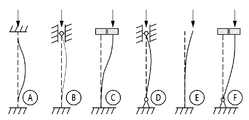
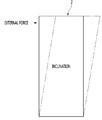
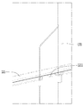
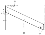
도 8은 직립한 진공단열체에 대하여 주어지는 다양한 하중조건을 모델링한 도면이다. 8 is a diagram modeling various load conditions given to an upright vacuum insulator.
도 8을 참조하면, A는 상하 모두가 자유단일 때의 변형을 모델링이고, B는 하측이 고정단 상측이 상하방향에 대해서 자유단일 때의 모델링이고, C는 하측이 고정단 상측이 좌우방향에 대해서 자유단일 때의 모델링이고, D는 하측이 회전자유단이고 상측이 상하방향에 대해서 자유단일 때의 모델링이고, E는 하측이 고정단이고 상측이 전방향에 대하여 자유단 일때의 모델링이고, F는 하측이 회전자유단이고 상측이 좌우방향에 대해서 자유단일 때의 모델링이다. Referring to FIG. 8, A is modeling deformation when both upper and lower sides are free ends, B is modeling when the lower side is a free end with respect to the upper and lower ends of the fixed end, and C is a lower side with a fixed end upper side in the left and right directions. Is a model when the free end is for D, D is a model when the lower side is a free end for the upper and the upper side is a free end for the up and down direction, E is a model when the lower side is a fixed end, and the upper side is a free end for all directions, F Is modeling when the lower side is a free end and the upper side is a free end with respect to the left and right directions.
발명자는 여러 하중에 대하여 검토를 수행하여, 도 8의 다양한 하중이 직립의 진공단열체, 특히 냉장고에 대하여 미치는 영향을 분석하였다. The inventor conducted a review on various loads, and analyzed the effect of various loads in FIG. 8 on the upright vacuum insulator, especially the refrigerator.
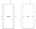
하중은 미시적으로 진공단열체의 플레이트 부재(10)(20)의 접근이라는 영향을 가질 수 있으나, 이는 서포팅유닛에 의해서 제어될 수 있는 부분이다. 발명자는 거시적으로 진공단열체의 구조에 영향을 미칠 수 있는, 벤딩, 변형 및 좌굴 등에 대하여 검토하여 도 9 내지 도 11과 같이 진공단열체가 변형될 수 있는 것을 확인하였다. 본 도면은 모두 본체 측 진공단열체를 정면에서 개략적으로 관찰하는 도면이다. The load may have the influence of microscopically approaching the
도 9를 참조하면, 본 도면은 진공단열체의 편평한 어느 일면에 하중이 발생되는 경우를 도시하고 있고, 이 경우에는 진공단열체의 어느 일면이 볼록하거나 오목하게 변형될 수 있다. 이와 같은 변형은 어느 일면에 상대적으로 큰 수직하중이 발생하는 경우에 발생할 수 있다.Referring to FIG. 9, this figure shows a case where a load is generated on one flat surface of the vacuum insulator, and in this case, one surface of the vacuum insulator may be convex or concavely deformed. Such deformation may occur when a relatively large vertical load is generated on one surface.
도 10을 참조하면, 본 도면은 진공단열체의 상단에 수평방향으로 외력이 발생되는 경우를 도시하고 있고, 이 경우에는 진공단열체의 상단부가 일방향으로 전체적으로 경사지게 변형될 수 있다. 이와 같은 변형은 제품의 이동이나 일방향 밀림 시에 발생할 수 있다. Referring to FIG. 10, this figure shows a case in which an external force is generated in the horizontal direction on the top of the vacuum insulator, and in this case, the upper end of the vacuum insulator may be deformed to be inclined as a whole in one direction. Such deformation may occur when the product is moved or pushed in one direction.
도 11을 참조하면, 본 발명은 진공단열체가 냉장고 등과 같이 개구부를 가지는 제품에 적용되고, 그 제품이 수직하중을 받을 때의 경우이다. 이 때에는, 진공단열체의 개구된 부분의 테두리가 오목하거나 볼록하게 변형될 수 있다. Referring to FIG. 11, the present invention is a case in which a vacuum insulator is applied to a product having an opening such as a refrigerator, and the product is subjected to a vertical load. At this time, the rim of the opened portion of the vacuum insulator may be concave or convexly deformed.
상술되는 하중이 진공단열체에 작용하여 발생하는 변형을 방지하기 위한 실시예가 이하에 도시된다. 이하에서는 냉장고를 주된 실시예로 이용하여 진공단열체의 변형을 방지하는 구성에 대하여 설명하지만, 실시예의 적용은 냉장고에 제한되지 않고 다양한 물품에 적용될 수 있다. An embodiment for preventing deformation caused by the above-described load acting on the vacuum insulator is shown below. Hereinafter, a configuration for preventing deformation of the vacuum insulator using the refrigerator as the main embodiment will be described, but the application of the embodiment is not limited to the refrigerator and can be applied to various articles.
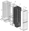
도 12는 실시예에 따른 냉장고의 분해 사시도이다. 12 is an exploded perspective view of a refrigerator according to an embodiment.
도 12를 참조하면, 플레이트 부재(10)(20), 상기 플레이트 부재의 사이 간격부에 도입되는 서포팅 유닛(30), 전도저항쉬트(60), 및 도어(3)는 이미 설명된 바와 같이 제시되므로 자세한 설명은 기 설명된 것을 참조할 수 있다. Referring to FIG. 12, the
상기 플레이트 부재(10)(20)의 내부 공간, 즉 진공공간부(50)의 안에는 서포팅 유닛(30)에 더해서, 진공단열체의 강도를 보강하기 위한 보강 프레임(120)이 삽입될 수 있다. 상기 전도저항쉬트(60)를 외부에서 보호하기 위하여 실링프레임(200)이 본체(2)와 도어(3)가 접촉되는 경계면에 더 개입될 수 있다. 상기 제 1 플레이트 부재(10)의 내부 고내 공간이 분리되어, 냉장 및 냉동의 목적에 따른 온도를 유지할 수 있도록 하기 위하여 멀리언(300)이 삽입될 수 있다. In addition to the supporting
상기 실링프레임은 상기 가스켓이 접하고, 상기 제 3 공간과 상기 도어의 사이에 놓일 수 있다. The sealing frame may be in contact with the gasket and may be placed between the third space and the door.
상기 보강 프레임(120)에 대하여 더 상세하게 설명한다. The reinforcing
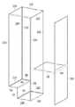
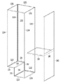
상기 보강 프레임(120)은, 상기 진공공간부(50)의 모서리 부위에 설치될 수 있다. 다시 말하면, 서로 다른 평면이 만나는 모든 경계선에 해당하는 모서리에 모두 제공될 수 있다. 상세하게는, 진공단열체의 후면 모서리 부분에 제공되는 후면 프레임(121)과, 진공단열체의 전면 모서리 부분에 제공되는 전면 프레임(123)과, 상기 전면 프레임(123)과 후면 프레임(121)을 연결하는 측방향에 제공되는 측면 프레임(122)을 포함할 수 있다. The reinforcing
상기 보강 프레임(120)은 상기 플레이트 부재에 비하여 두껍거나 강한 재질로 제공되어 플레이트 부재에 접촉될 수 있다. The reinforcing
상기 전면 프레임(123), 상기 후면 프레임(121), 및 상기 측면 프레임(122)은 서로 체결되어 한 몸으로 제공되어 기기의 강도를 보강할 수 있다. The
도 11에서 설명된 바와 같이, 진공단열체의 개구부가 오목하거나 볼록하게 변형되는 것을 방지하기 위하여, 멀리언(300)을 안착시키는 멀리언 안착 프레임(130) 및 멀리언 전방 프레임(140)을 더 제공할 수 있다. 상기 멀리언 안착 프레임(130) 및 상기 멀리언 전방 프레임(140)은 보강 프레임(120)과는 달리 제 1 플레이트 부재(10)의 내면에 제공될 수 있다. 이로써 멀리언(300)의 지지 및 연결작업을 수행할 수 있다. 11, in order to prevent the opening of the vacuum insulator from being concave or convexly deformed, the
상기 멀리언(300)이 제공되지 않는 경우에 진공단열체의 개구부의 변형을 방지하기 위하여 상기 멀리언 전방 프레임이 제공될 수 있다. 이 경우에 상기 멀리언 전방 프레임은 줄여서 전방 프레임이라고 칭할 수 있다. When the
상기 멀리언 안착 프레임(130) 및 상기 멀리언 전방 프레임(140)은, 상기 멀리언(300)을 고내의 소정 위치에 놓이도록 하는 역할을 수행하는 것은 물론이다. 이에 더해서, 상하로 연장되는 네 개의 후면 프레임(121) 및 전면 프레임(123) 중에서 인접하는 한 쌍의 프레임의 강도를 보강할 수 있다. 예를 들어 상기 멀리언 전방 프레임(140)은 상하로 연장되는 한 쌍의 전면 프레임(123)을 지지하여, 도 11에서 설명된 바와 같은 진공단열체의 개구부의 변형을 방지할 수 있다. Needless to say, the
상기 멀리언 안착 프레임(130) 및 상기 멀리언 전방 프레임(140)은 상기 보강 프레임(120)과는 직접적으로는 분리되어 있고, 별도의 다른 부재에 의해서 간접적으로 서로 연결되어 강도를 보강할 수 있다. The
강도 보강의 작용을 위하여, 상기 보강프레임(120), 멀리언 안착 프레임(130), 및 멀리언 전방 프레임(140)은 소정의 강도가 있는 재질로서, 플레이트 부재(10)(20)와 비교할 때 견고한 소재를 적용하거나 두꺼운 재료를 사용할 수 있다. For the action of strength reinforcement, the
이에 따르면, 상기 보강프레임(120)의 일 부분으로서 제공되는, 후면 프레임(121), 전면 프레임(123), 및 측면 프레임(122)에 더하여, 상기 멀리언 안착 프레임(130) 및 멀리언 전방 프레임(140)도 보강프레임으로서의 기능이 수행될 수 있다. 따라서, 상기 후면 프레임(121)을 제 1 보강프레임이라고 이름하고, 상기 전면 프레임(123)을 제 2 보강프레임이라고 이름할 수 있다. 나아가서, 상기 제 1 보강프레임 및 상기 제 2 보강프레임을 연결하는 측방향에 제공되는 상기 측면 프레임(122)을 제 3 보강프레임이라고 할 수 있다. 이와 함께 상기 멀리언 안착 프레임(130) 및 상기 멀리언 전방 프레임(140)을 제 4 보강프레임이라고 할 수 있다. 상기 상기 멀리언 안착 프레임(130)이 제공되지 않는 경우에는 상기 멀리언 전방 프레임(140)을 제 4 보강프레임이라고 할 수도 있다.According to this, in addition to the
상기 제 1 보강프레임과 제 2 보강프레임은, 상기 진공단열체의 상단이 어느 방향으로 전체적으로 경사지게 변형하는 것을 방지할 수 있다. 이를 위하여 도시된 바와 같이, 상기 제 1, 2 보강프레임은, 상기 진공단열체의 상하방향으로 형성된 모서리를 따라 연장되어 상기 모서리 인근에 위치할 수 있다. 여기서, 모서리는 상기 진공단열체의 서로 다른 평면이 만나는 경계선이라고 할 수 있다. The first reinforcing frame and the second reinforcing frame can prevent the upper end of the vacuum insulator from being deformed as a whole in a certain direction. As shown for this, the first and second reinforcing frames may extend along edges formed in the vertical direction of the vacuum insulator to be located near the edges. Here, the corner may be referred to as a boundary line where different planes of the vacuum insulator meet.
상기 제 1, 2 보강 프레임은 상기 제 1 플레이트 부재와 상기 제 2 플레이트 부재 중의 적어도 하나에 제공될 수 있다. The first and second reinforcement frames may be provided on at least one of the first plate member and the second plate member.
상기 제 2 보강프레임은 상기 진공단열체의 상측부의 전체적인 경사를 방지할뿐만 아니라, 상기 진공단열체의 개구된 부분의 테두리가 오목하거나 볼록하게 변형하는 것을 방지할 수 있다. 이를 위하여 상기 진공단열체의 상기 테두리를 따라 연장되어 상기 테두리 인근에 위치할 수 있다. The second reinforcing frame not only prevents the overall inclination of the upper portion of the vacuum insulator, but also prevents the rim of the opened portion of the vacuum insulator from concave or convex deformation. To this end, it may extend along the rim of the vacuum insulator and be located near the rim.
상기 제 4 보강프레임은, 상기 개구된 부분의 테두리가 변형하는 것을 방지할 수 있도록 상기 개구를 가로지르는 방향으로 연장되어 형성될 수 있다. The fourth reinforcing frame may be formed to extend in a direction transverse to the opening so as to prevent deformation of the rim of the opened portion.
한편, 추후에 더 상세하게 설명되지만, 상기 멀리언(300)에는 멀리언 냉기유로(310)가 제공되어 멀리언(300)에 의해서 구분되는 두 저장공간을 냉기가 통과할 수 있도록 할 수 있다. On the other hand, although described in more detail later, the
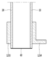
도 13은 진공단열체의 후면 모서리 부분의 부분 절개 단면도이다. 13 is a partial cutaway cross-sectional view of a rear edge portion of the vacuum insulator.
도 13을 참조하면, 상기 후면 프레임(121)은 제 2 플레이트 부재(20)의 절곡된 모서리에 단면 형상에 맞추어 절곡된 형상으로 제공된다. 상기 후면 프레임(121)은 제 2 플레이트 부재(20)의 후면부와 측면부를 함께 지지하므로 각 면의 강도를 보강할 수 있다. 뿐만 아니라, 상기 후면 프레임(121)은 높은 관성으로 진공단열체의 굽힘 및 좌굴에 대항하여 강도를 보강할 수 있다. Referring to FIG. 13, the
상기 후면 프레임(121)의 각 면은 대응하는 제 2 플레이트 부재(20)의 각 면에 용접 또는 기계적 체결 방식으로 일체화될 수 있다. Each surface of the
상기 후면 프레임(121)은 진공공간부(50)의 내면에 장착됨으로써, 외부에 드러나는 부분이 없으므로 기기의 제작공정에서 간섭 등의 문제가 발생하지 않는다. Since the
도면에서는 후면 프레임(121)을 예시하여 나타내고 있지만, 다른 보강 프레임(120)도 마찬가지의 단면 형상으로 제공되고, 진공단열체의 동일한 위치에서 모서리를 따라서 연장될 수 있다. 다른 보강 프레임도 상기 후면 프레임(121)과 마찬가지의 강도보강작용을 수행할 수 있다. 경우에 따라서, 상기 보강 프레임(120)은 모든 프레임이 서로 직접 연결되어 강도보강에 대한 신뢰성을 더욱 높일 수도 있다. 이는 다른 도면의 보강 프레임(120)에 대해서도 마찬가지로 적용될 수 있다. In the drawing, although the
도 14는 다른 실시예에 따른 후면 프레임을 설명하는 진공단열체의 단면도이다. 14 is a cross-sectional view of a vacuum insulator illustrating a rear frame according to another embodiment.
도 14를 참조하면, 상기 후면 프레임(121)은 제 1 플레이트 부재(10)의 내면에 장착된다. 다른 보강 프레임(120)도 마찬가지로 제공될 수 있다. 14, the
상세하게 본 실시예의 경우에, 상기 후면 프레임(121)은 제 1 플레이트 부재(10) 내면의 절곡된 모서리와 같은 형상으로 단면 형상이 절곡된 형상으로 제공될 수 있다. 상기 후면 프레임(121)은 제 1 플레이트 부재(10) 내면의 후면부와 측면부를 함께 지지하므로 각 면의 강도를 보강할 수 있다. 뿐만 아니라, 상기 후면 프레임(121)은 높은 관성으로 진공단열체의 굽힘 및 좌굴에 대항하여 강도를 보강할 수 있다. In detail, in the case of this embodiment, the
상기 후면 프레임(121)의 각 면은 대응하는 제 1 플레이트 부재(10)의 각 면에 용접 또는 기계적 체결 방식으로 일체화될 수 있다. Each side of the
상기 후면 프레임(121)은, 상기 멀리언 안착 프레임(130) 및 상기 멀리언 전방 프레임(140)과 일체화 될 수 있으므로 전체적인 강도보강작용의 안정성이 높아지는 장점이 있다. Since the
상기 후면프레임은 상기 진공공간부(50)의 외면에 장착됨으로써, 서포팅 유닛(30)의 설치 시에 간섭 등의 문제가 발생하지 않는다. 따라서 진공단열체의 미시적인 변화를 방지할 수 있다. The rear frame is mounted on the outer surface of the
도면에서는 후면 프레임(121)을 예시하여 나타내고 있지만, 다른 보강 프레임(120)도 마찬가지의 단면 형상으로 제공되고, 진공단열체의 동일한 위치에서 모서리를 따라서 연장될 수 있다. 다른 보강 프레임도 상기 후면 프레임(121)과 마찬가지의 강도보강작용을 수행할 수 있다. In the drawing, although the
도 15는 다른 실시예에 따른 후면 프레임을 설명하는 진공단열체의 단면도이다. 15 is a cross-sectional view of a vacuum insulator illustrating a rear frame according to another embodiment.
도 15를 참조하면, 상기 후면 프레임(121)은 제 1 플레이트 부재(10)의 외면에 장착된다. 다른 보강 프레임(120)도 마찬가지로 제공될 수 있다. 15, the
상세하게 본 실시예의 경우에, 상기 후면 프레임(121)은 제 1 플레이트 부재(10) 외면의 절곡된 모서리와 같은 형상으로 단면 형상이 절곡된 형상으로 제공될 수 있다. 상기 후면 프레임(121)은 제 1 플레이트 부재(10) 외면의 후면부와 측면부를 함께 지지하므로 각 면의 강도를 보강할 수 있다. 뿐만 아니라, 상기 후면 프레임(121)은 높은 관성으로 진공단열체의 굽힘 및 좌굴에 대항하여 강도를 보강할 수 있다. In detail, in the case of this embodiment, the
상기 후면 프레임(121)의 각 면은 대응하는 제 1 플레이트 부재(10) 외면의 각 면에 용접 또는 기계적 체결 방식으로 일체화될 수 있다. Each surface of the
상기 후면프레임은 상기 진공공간부(50)의 내면에 장착됨으로써, 기기의 외부에 드러나는 부분이 없으므로 기기의 제작공정에서 간섭 등의 문제가 발생하지 않는다. Since the rear frame is mounted on the inner surface of the
도면에서는 후면 프레임(121)을 예시하여 나타내고 있지만, 다른 보강 프레임(120)도 마찬가지의 단면 형상으로 제공되고, 진공단열체에 대하여 동일한 위치에서 모서리를 따라서 연장되어 서로 일체화될 수 있다. 다른 보강 프레임도 상기 후면 프레임(121)과 마찬가지의 강도보강작용을 수행할 수 있다.In the drawing, although the
도 16은 다른 실시예에 따른 후면 프레임을 설명하는 진공단열체의 단면도이다. 16 is a cross-sectional view of a vacuum insulator illustrating a rear frame according to another embodiment.
도 16을 참조하면, 상기 후면 프레임(121)은 제 2 플레이트 부재(20)의 외면에 장착된다. 다른 보강 프레임(120)도 마찬가지로 제공될 수 있다. Referring to FIG. 16, the
상세하게 본 실시예의 경우에, 상기 후면 프레임(121)은 제 2 플레이트 부재(20) 외면의 절곡된 모서리와 같은 형상으로 단면 형상이 절곡된 형상으로 제공될 수 있다. 상기 후면 프레임(121)은 제 2 플레이트 부재(20) 외면의 후면부와 측면부를 함께 지지하므로 각 면의 강도를 보강할 수 있다. 뿐만 아니라, 상기 후면 프레임(121)은 높은 관성으로 진공단열체의 굽힘 및 좌굴에 대항하여 강도를 보강할 수 있다. In detail, in the case of this embodiment, the
상기 후면 프레임(121)의 각 면은 대응하는 제 2 플레이트 부재(20) 외면의 각 면에 용접 또는 기계적 체결 방식으로 일체화될 수 있다. Each side of the
상기 후면프레임은 상기 진공공간부(50)의 외면에 장착됨으로써, 제조공정 상의 복잡함이 없이 제조한 다음에, 진공단열체의 마지막 공정에서 제 2 플레이트 부재(20)의 외면에 체결할 수 있다. 이에 따르면 제조공정이 간략화되는 장점을 얻을 수 있다. The rear frame can be fastened to the outer surface of the
도면에서는 후면 프레임(121)을 예시하여 나타내고 있지만, 다른 보강 프레임(120)도 마찬가지의 단면 형상으로 제공되고, 진공단열체에 대하여 동일한 위치에서 모서리를 따라서 연장되어 서로 일체화될 수 있다. 다른 보강 프레임도 상기 후면 프레임(121)과 마찬가지의 강도보강작용을 수행할 수 있다.In the drawing, although the
본 실시예의 경우에는, 진공단열체의 외부, 상세하게는 본체(2)의 개구를 통하여, 상기 멀리언 안착 프레임(130) 및 상기 멀리언 전방 프레임(140)과 일체화 될 수 있다. 이에 따라서 전체적인 강도보강작용의 안정성이 높아지는 장점이 있다. In the case of the present embodiment, through the opening of the vacuum insulator, specifically, the
상기 도 14 내지 도 16을 참조하면, 상기 보강 프레임(120)은 상기 플레이트 부재 보다 두껍게 제공되어 진공단열체의 강도를 보강할 수 있다. 상기 보강 프레임(120) 진공단열체의 모서리를 따라서 일 방향으로 길게 연장된다. 상기 보강 프레임(120)의 자기의 연장방향에 대하여 굽힘에 저항하는 보(beam)의 기능을 수행할 수 있다. 14 to 16, the reinforcing
이를 위하여 충분한 관성모멘트 얻기 위하여, 보강 프레임의 단면에서 관찰할 때, 상기 보강 프레임(120)의 단면길이(L)는 상기 진공공간부의 두께(W)보다는 길게 제공된다. 다시 말하면, 도 14 내지 도 16에서 제시되는 보강 프레임(120)의 단면에서, 어느 일 방향으로 연장되는 보강 프레임(120)의 단면길이(L))는 상기 진공공간부의 두께(W)보다는 크게 제공되는 것이다. 이에 따르면, 충분한 굽힘에 저항하는 충분한 관성모멘트를 얻어낼 수 있다. To achieve this, in order to obtain a sufficient moment of inertia, when observing from the cross-section of the reinforcement frame, the cross-sectional length L of the
또한, 상기 보강 프레임(120)의 단면길이는 상기 보강 프레임(120)의 연장방향의 길이에 비하여 작게 제공될 수 있다. 다시 말하면, 도 14 내지 도 16에서 진공단열체의 모서리를 따라서 연장되는 보강 프레임(120)의 전체 길이보다는 보강 프레임의 단면길이는 작게 제공될 수 있는 것이다.In addition, the cross-sectional length of the reinforcing
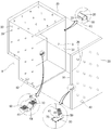
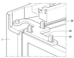
도 17은 보강 프레임이 설치된 진공단열체에 열교환관로가 도시된 도면이다. 17 is a view showing a heat exchange channel in a vacuum insulator with a reinforcement frame installed.
도 17을 참조하면, 냉동 시스템에는 증발기 전후의 냉매관로는, 냉동사이클의 열효율을 향상시키기 위하여, 서로 열교환이 수행되도록 한다. 이들 냉매가 열교환되는 관로는 열교환관로(170)라고 이름할 수 있다. 상기 열교환관로(170)는 고내 또는 고외에 설치하는 경우에 필요없는 공간을 차지하기 때문에 진공단열체의 내부, 즉 진공공간부(50)의 내부에 소정의 길이로 제공될 수 있다. Referring to FIG. 17, in the refrigeration system, the refrigerant pipes before and after the evaporator allow heat exchange with each other in order to improve the thermal efficiency of the refrigeration cycle. The conduit through which these refrigerants exchange heat may be referred to as a
상기 보강 프레임(120) 중에서 후면 프레임(121)은 기계실(8)로 인입출되는 상기 열교환관로(170)의 경로에 제공된다. 따라서 상기 열교환관로(170)는 진공공간부(50)를 빠져나오면서 상기 후면 프레임(121)을 통과해야 한다. 상기 후면 프레임(121)은 강도를 보강하기 위하여 소정의 두께 뿐만 아니라 소정의 면적과 길이로 제공된다. 따라서 열교환관로(170)가 후면 프레임(121)과 직접 접촉되면 양자간에 열교환이 발생하여 열손실이 발생한다. Of the reinforcing
상기 문제를 해결하기 위하여, 실시예에서는 상기 열교환관로(170)가 통과화는 부분에서 상기 후면 프레임(121)의 일부가 제거될 수 있다. 상기 후면 프레임(121)에서 제거되는 부분은 평면 구조 상에서 일부가 완전히 절개될 수도 있고, 절개되어야 할 부분에서 후면 프레임(121)의 두께가 다른 부분에 비하여 얇게 제공되어 수직구조 상에서 일부가 제거될 수도 있다. 두 가지 경우 모두 열교환관로(170)와 후면 프레임(121) 간이 열전달량을 줄여서 열손실을 줄일 수 있다. In order to solve the above problem, in an embodiment, a part of the
도 18은 후면 프레임이 절개되는, 도 17에서 A부분을 확대하여 나타내는 도면이다. FIG. 18 is an enlarged view of part A in FIG. 17 in which the rear frame is cut.
도 18을 참조하면, 상기 후면 프레임(121)의 수평부분이 절개되어 후면 프레임 절개부(1211)을 이루는 것을 확인할 수 있다. 상기 열교환관로(170)는 후면 프레임(121)에 접하지 않고 통과하므로 열손실이 발생하지 않는다. 상기 열교환관로(170)가 다른 보강 프레임(120)을 통과하는 경우에는 다른 보강 프레임(120)에 프레임 절개부가 제공될 수 있는 것도 충분히 예상할 수 있다. Referring to FIG. 18, it can be seen that the horizontal portion of the
상기 후면 프레임 절개부(1211)가 제공되는 영역은, 실링을 위하여 도 4에 다양하게 제시되는 밀봉방식이 적용될 수도 있고, 열교환관로(170)와 플레이트 부재 간의 용접에 의해서 밀봉이 수행되도록 할 수 있다. In the region where the
상기 열교환관로(170)외에 열손실을 일으키는 다양한 관로가 통과되는 경로 상에 놓이는 보강 프레임(120)에는 프레임 절개부가 더 제공될 수 있는 것도 용이하게 이해할 수 있다. In addition to the
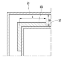
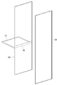
도 19는 다른 실시예에 따른 보강 프레임을 설명하는 진공단열체의 단면사시도로서, 진공단열체의 전면부를 도시한다. 19 is a sectional perspective view of a vacuum insulator explaining a reinforcement frame according to another embodiment, showing a front portion of the vacuum insulator.
도 19를 참조하면, 본 실시예는 상기 진공공간부(50)에 두 개의 이격되는 보강 프레임이 제공되고, 하나는 단면이 절곡형으로 제공되고, 다른 하나는 단면이 일자형으로 제공될 수 있다. 이 구성에 따르면 진공단열체의 강도를 높이면서도, 두 보강부재 간의 간섭을 방지하여 제작 시에 작업이 간편한 이점을 얻을 수 있다.Referring to FIG. 19, in the present exemplary embodiment, two spaced apart reinforcing frames are provided in the
상기 제 1 플레이트 부재(10)의 외면에는 단면이 평면인 제 2 전면 내측 프레임(1232)가 마련되고, 상기 제 2 플레이트 부재(20)의 내면에는 단면이 단면이 절곡형인 제 1 전면 내측 프레임(1231)이 마련될 수 있다. 상기 제 1 전면 내측 프레임(1231)이 절곡되는 위치는 제 2 플레이트 부재(20) 단부의 안쪽에 위치하도록 한다. 이로써 진공압에 의해서 전도저항쉬트(60)가 곡면으로 변형될 때 접촉이 방지되어 냉기손실을 방지할 수 있다. A second front
상기 제 2 전면 내측 프레임(1232) 및 상기 제 1 전면 내측 프레임(1231)은 서로 접촉 및 접근이 허용되지 않도록 하는 것이 바람직하다. 이로써 보강 프레임 간의 열전도 및 열복사를 차단하여 냉기손실을 방지할 수 있다. It is preferable that the second front
본 실시예에 따른 보강 프레임은, 도시되는 바와 같은 상기 전면부뿐만 아니라, 진공단열체의 후면부 및 측면부에도 동일한 형태로 제공되고, 서로 연결되어 제공될 수 있다. 이 경우에는 제 1, 2 플레이트 부재 각각에 체결되는 보강 프레임은 다른 플레이트 부재의 보강 프레임과는 접촉 및 접근이 허용되지 않도록 함으로서, 냉기손실을 방지하는 것이 중요하다. The reinforcing frame according to the present embodiment may be provided in the same form as shown in the front portion, as well as in the rear portion and the side portion of the vacuum insulator, and may be provided in connection with each other. In this case, it is important to prevent cold air loss by preventing the reinforcing frame fastened to each of the first and second plate members from being allowed to contact and access the reinforcing frame of the other plate member.
상기 제 1 전면 내측 프레임(1231) 또는 상기 제 2 전면 내측 프레임(1232)이 단독으로 제공될 수도 있다. 상기 제 1 전면 내측 프레임(1231)은 절곡형으로서, 플레이트 부재 간이 전도열 저감을 위하여, 상기 플레이트 부재에 대하여 수직방향으로 연장되는 상기 제 1 전면 내측 프레임(1231)의 수직방향의 길이는 상기 제 3 공간의 높이보다 작게 제공될 수 있다. The first front
도 20는 다른 실시예에 따른 보강 프레임을 설명하는 진공단열체의 단면사시도로서, 진공단열체의 전면부를 도시한다. 20 is a sectional perspective view of a vacuum insulator explaining a reinforcement frame according to another embodiment, showing a front portion of the vacuum insulator.
도 20을 참조하면, 본 실시예는 상기 진공공간부(50)의 내부에 한 개의 보강 프레임이 제공되고, 상기 진공공간부(50)의 외부에 한 개의 보강 프레임이 제공된다. 이때에도 하나는 단면이 절곡형으로 제공되고, 다른 하나는 단면이 일자형으로 제공될 수 있다. 이 구성에 따르면 진공단열체의 강도를 높이면서도, 두 보강부재 간의 간섭을 더 확실하게 방지하여 제작 시에 작업이 간편한 이점을 얻을 수 있다.Referring to FIG. 20, in the present embodiment, one reinforcement frame is provided inside the
상기 제 1 플레이트 부재(10)의 내면에는 단면이 절곡형으로 전면 절곡형 프레임(1234)이 마련되고, 상기 제 2 플레이트 부재(20)의 내면에는 단면이 일자형으로 전면 일자형 프레임(1233)이 마련될 수 있다. 상기 전면 절곡형 프레임(1234)의 절곡되는 위치는 제 2 플레이트 부재(20) 단부의 바깥쪽에 위치하도록 한다. 이로써 더 냉장고의 본체 측에 가하여지는 굽힘강도에 저항하는 관성을 더 크게 할 수 있다. 상기 전도저항쉬트(60)가 곡면으로 변형하더라도, 상기 전면 절곡형 프레임(1234)은 진공공간부의 외부에 놓이므로, 전도저항쉬트(60)가 전면 절곡형 프레임(1234)에 접촉될 우려도 없다. The inner surface of the
본 실시예에 따른 보강 프레임은, 도시되는 바와 같은 상기 전면부뿐만 아니라, 진공단열체의 후면부 및 측면부에도 동일한 형태로 제공되고, 서로 연결되어 제공될 수 있다. 이 경우에는 제 1, 2 플레이트 부재 각각에 체결되는 보강 프레임은 다른 플레이트 부재의 보강 프레임과는 애초에 접촉되지 않으므로 보강 프레임 간의 접촉 및 접근에 의한 열손실은 발생하지 않는다. The reinforcing frame according to the present embodiment may be provided in the same form as shown in the front portion, as well as in the rear portion and the side portion of the vacuum insulator, and may be provided in connection with each other. In this case, since the reinforcing frames fastened to each of the first and second plate members are not initially contacted with the reinforcing frames of other plate members, heat loss due to contact and access between the reinforcing frames does not occur.
도 21은 다른 실시예에 따른 보강 프레임을 설명하는 진공단열체의 단면도로서, 진공단열체의 전면부를 도시한다. 21 is a cross-sectional view of a vacuum insulator explaining a reinforcement frame according to another embodiment, and shows a front portion of the vacuum insulator.
도 21을 참조하면, 본 실시예는 상기 진공공간부(50)에 한 개의 보강 프레임이 제공되고, 상기 진공공간부(50)의 외부 고내측에 한 개의 보강 프레임이 제공된다. 이때 하나의 보강 프레임은 단면이 절곡형으로 제공되고, 다른 하나의 보강 프레임은 단면이 일자형으로 제공될 수 있다. 이 구성에 따르면 진공단열체의 강도를 높이면서도, 두 보강부재 간의 간섭을 방지하여 제작 시에 작업이 간편한 이점을 얻을 수 있다.Referring to FIG. 21, in the present embodiment, one reinforcing frame is provided in the
상기 제 1 플레이트 부재(10)의 외면에는 단면이 평면인 전면 일자형 프레임(1233)이 마련되고, 상기 제 1 플레이트 부재(10)의 내면에는 단면이 절곡형인 전면 절곡형 프레임(1234)이 마련될 수 있다. 도 20에 제시되는 실시예와 마찬가지로 전면 절곡형 프레임(1234)의 절곡되는 위치는 제 1 플레이트 부재(10) 단부의 바깥쪽에 위치하도록 한다. 그에 따른 작용효과도 마찬가지이다. On the outer surface of the
본 실시예에 따른 보강 프레임은, 도시되는 바와 같은 상기 전면부뿐만 아니라, 진공단열체의 후면부 및 측면부에도 동일한 형태로 제공되고, 서로 연결되어 제공될 수 있다. The reinforcing frame according to the present embodiment may be provided in the same form as shown in the front portion, as well as in the rear portion and the side portion of the vacuum insulator, and may be provided in connection with each other.
본 실시예의 경우에는, 상기 제 1 플레이트 부재(10)에만 보강 프레임이 제공되고, 상기 제 2 플레이트 부재(20)에는 보강 플레이트가 제공되지 않을 수 있다. 이 경우에도 서포팅 유닛(30)에 의한 지지 작용에 의해서 진공단열체의 전체적인 구조 강도는 지지될 수 있다. In the case of this embodiment, only the
본 실시예의 경우에는, 진공단열체가 적용되는 냉장고 등의 기기에 작용에 필요한 부품 들이, 상기 전면 절곡형 프레임(1234)에 지지될 수 있기 때문에, 보강 프레임은 강도보강 및 부품 지지라는 두 가지의 작용을 함께 수행할 수 있다. In the case of the present embodiment, since the parts necessary for the operation of a device such as a refrigerator to which a vacuum insulator is applied can be supported by the front
도 22는 다른 실시예에 따른 보강 프레임을 설명하는 진공단열체의 단면도로서, 진공단열체의 전면부를 도시한다. 22 is a cross-sectional view of a vacuum insulator explaining a reinforcement frame according to another embodiment, and shows a front portion of the vacuum insulator.
도 21을 참조하면, 본 실시예는 전면 일자형 프레임(1233)이 제 2 플레이트 부재(1233)의 내면이 아니라 외면에 설치되는 것이 특징적으로 달라진다. 본 실시예는, 진공압의 인가에 따른 상기 전도저항쉬트(60)의 곡면변형이 크거나, 서포팅유닛(30)이 진공단열체의 단부까지 연장될 필요가 있는 경우에, 보강 프레임에 의한 간섭을 피하기 위한 경우에 바람직하게 적용될 수 있다. Referring to FIG. 21, the present embodiment is characterized in that the front straight-shaped frame 1303 is installed on the outer surface, not the inner surface of the
본 실시예의 상기 전면 일자형 프레임(1233)은 제 2 플레이트 부재(20)의 외면에 놓이더라도 간섭이 발생하지 않는 일자형으로 제안될 수 있다. 가장 많은 굽힘하중이 발생하는 부분, 즉 본체 측 진공단열체 개구에 있어서 최외각의 테두리 부분에 대하여, 직접 강도를 보강할 수 있는 장점이 있다. 따라서 도 11에 설명된 바와 같은 냉장고의 개구에 대한 변형에 저항하는 힘을 크게 할 수 있다. The front
도 23 및 도 24는 진공단열체의 어느 일 꼭지점 부분을 보이는 사시도로서, 도 23은 도어힌지가 설치되기 전이고, 도 24는 도어힌지가 설치된 상태에서의 도면이다. 23 and 24 are perspective views showing a part of a vertex of a vacuum insulator, FIG. 23 is before the door hinge is installed, and FIG. 24 is a view in which the door hinge is installed.
냉장고의 경우에 상기 도어 측 진공단열체가 상기 본체 측 진공단열체에 회동이 가능한 상태로 체결되기 위하여, 그 접속부에는 도어힌지가 마련된다. 상기 도어힌지는 스스로가 소정의 강도를 가진다. 상기 도어가 체결된 상태에서 도어 자중에 의한 도어처짐을 방지하고 본체의 뒤틀림을 방지하기 위하여, 상기 도어힌지는 보강프레임(120)에 의해서 지지되는 것이 바람직하다. 상기 도어 힌지와 상기 보강 프레임(120)의 경계에는 플레이트 부재(20)가 개입될 수도 있다. In the case of a refrigerator, in order to fasten the door-side vacuum insulator to the vacuum insulator on the body-side, a door hinge is provided at the connecting portion. The door hinge itself has a certain strength. In order to prevent the door from sagging due to the weight of the door in the state where the door is fastened and to prevent warping of the main body, the door hinge is preferably supported by the reinforcing
도 23을 참조하면, 도어 힌지(263)가 체결되도록 하기 위하여, 상기 본체 측 진공단열체에는 도어 체결구(260)가 마련된다. 상기 도어 체결구(260)는 세 개가 제공될 수 있다. 상기 도어 체결구(260)는 상기 제 2 플레이트 부재(20) 및/또는 상기 보강 프레임(120) 및/또는 별도의 추가보강부재(예를 들어, 제 2 플레이트 부재의 외면에 더 제공되는 추가 플레이트)에 직접 또는 간접으로 고정될 수 있다. 여기서 직접은 용접 등의 융착방법에 의한 것을 지칭할 수 있고, 간접은 융착 등의 방법이 아닌 보조체결도구 등을 이용한 체결방법을 지칭할 수 있다 Referring to FIG. 23, in order for the
상기 도어체결구(260)는 높은 지지강도가 요구되기 때문에 상기 제 2 플레이트 부재(20)에 접하여 체결될 수 있다. 이를 위하여, 상기 실링프레임(200)은 절개될 수 있다. 절개되는 실링프레임(200)은 절단면(261)을 가지고, 제 2 플레이트 부재(20)는 도어 체결구(260)가 체결되는 도어 체결구 안착면(262)을 가질 수 있다. 따라서 실링프레임(200)의 절개에 의해서 도어 체결구 안착면(262) 바깥으로 드러날 수 있고, 상기 도어 체결부 안착면(262)에는 추가적인 플레이트 부재가 더 개입될 수 있다. Since the
실링프레임(200)의 단부가 전체로서 제거되는 것이 아니라, 도어체결구(260)가 제공되는 부분에만 실링 프레임(200)의 일부분이 제거되도록 할 수도 있다. 그러나, 실링프레임(200)의 단부가 모두 제거되는 것이 제작의 편의, 및 도어 힌지(263)가 진공단열체 측에 견고하게 지지되어 체결되도록 하기 위하여 더 바람직할 수 있다. The end of the sealing
한편, 상기 보강프레임(120)은, 이미 설명한 바와 같이, 냉장고 본체의 모서리를 형성하는 두 면의 각각에 면접촉하여 강도를 보강한다. 상기 보강프레임(120)은, 상기 실링프레임(200)이 안착되는 상기 제 1 플레이트 부재(10) 및 상기 제 2 플레이트 부재(10)의 단부 중의 적어도 일측에 면으로 접촉할 수 있다. 따라서, 상기 도어힌지(263)은 상기 보강프레임(120)에 지지될 수 있다. On the other hand, the reinforcing
도 25와 도 26은 멀리언 부분에 제공되는 도어 힌지를 설명하는 도면이다. 도 25는 도어힌지가 설치된 모습이고, 도 26은 도어힌지가 설치되기 전 상태에서의 도면이다. 25 and 26 are views for explaining the door hinge provided in the mullion part. 25 is a state in which the door hinge is installed, and FIG. 26 is a view in a state before the door hinge is installed.
근래에는 상냉장 하냉동 방식의 냉장고가 각광을 받고 있다. 상기 상냉장 하냉동방식의 냉장고는, 진공단열체의 상하단 뿐만 아니라 멀리언 부분에 도어힌지가 설치된다. In recent years, refrigerators in the upper and lower refrigerators are in the spotlight. In the refrigerator of the upper and lower refrigeration method, the door hinge is installed not only at the upper and lower ends of the vacuum insulator, but also at the mullion.
도 25 및 도 26을 참조하면, 멀리언 부분에 도어힌지가 체결되도록 하기 위하여, 상기 멀리언 전방 프레임(140)이 소정 깊이 깎여서 제공되는 안착 리세스(1400)이 제공되고, 상기 안착 리세스에는 힌지 체결홈(1401)이 가공될 수 있다. 상기 실링 프레임(200)에는 안착 절개부(264)가 제공될 수 있다. 25 and 26, in order to secure the door hinge to the mullion portion, a
상기 안착 리세스(1400) 및 상기 안착 절개부(264)에는 도어 힌지(263)가 안착될 수 있다. 이 구조에 의해서 상기 도어 힌지(263)은 정확한 위치에 놓일 수 있다. 상기 도어 힌지(263)이 안착된 상태에서, 상기 힌지 체결홈(1401)에 나사 등의 체결구가 끼워져서 상기 도어 힌지(263)이 체결될 수 있다. 이 때 상기 체결구는 보강 프레임까지 연장되어 체결력을 강화시킬 수 있다. 물론 상기 체결구에 의한 체결방식이 아닌 용접 등의 방식이 적용될 수도 있다. A
도 27은 멀리언 지지 프레임의 사시도이다. 27 is a perspective view of the mullion support frame.
도 27을 참조하면, 멀리언(300)이 진공단열체의 내부의 올바른 위치에 자리잡을 수 있도록 하기 위하여, 멀리언(300)이 놓이는 테두리를 따라서 멀리언 안착 프레임(130)이 제공될 수 있다. 상기 멀리언 안착 프레임(130) 단면의 적어도 일부는 절곡되는 형상으로 제공됨으로써, 정해진 자리에 놓인 멀리언(300)이 움직이지 않도록 할 수 있다. 상기 멀리언 안착 프레임(130)의 모든 부분의 단면이 절곡된 형상으로 제공됨으로써 관성이 커져서 보다 큰 굽힘응력 및 좌굴응력에 견딜 수 있다. Referring to FIG. 27, a
상기 멀리언 안착 프레임(130)은 상기 제 1 플레이트 부재(10)의 내면에 용접 등의 방식으로 체결될 수 있고, 경우에 따라서는 보강 프레임(120)에 까지 체결되어 그 체결력을 강화시킬 수도 있다. The
도면에서는 진공단열체 내면의 네 모서리 부분에 멀리언 안착 프레임(130)이 모두 놓이는 것으로 제공되지만, 어느 일면은 제공되지 않을 수도 있지만, 강도보강의 측면을 위하여 모두 제공되는 것이 바람직하다. In the drawing, the
상기 멀리언 안착 프레임(130)은 도 11에 도시된 바와 같은 진공단열체 개구 측의 변형, 특히 확장되는 방향의 변형을 방지하는 역할을 수행할 수 있다. 상기 멀리언 안착 프레임(130)에 더하여 상기 멀리언 전방 프레임(140)은 상기 진공단열체 개구측의 변형, 특히 축소되는 방향의 변형을 방지할 수 있다. 물론, 상기 멀리언 전방 프레임(140)이 상기 멀리언 안착 프레임(130)에 체결되는 경우에는 상기 진공단열체 개구측의 변형으로서 확장 및 축소에 모두 대응할 수도 있다. The
한편, 상기 진공단열체의 개구측의 테두리를 따라서는 보조 프레임(1301)이 더 설치될 수 있다. 상기 보조 프레임(1301)은 상기 멀리언 안착 프레임(130)에 한몸을 이루도록 상기 제 1 플레이트 부재(10)의 내면측에 설치될 수 있다. 상기 보강 프레임(120)이 제 1 플레이트 부재(10)의 내면측에 제공되는 도 14, 도 20, 도 21, 및 도 22의 경우에는 대응하는 각 프레임이 상기 보조 프레임(1301)의 역할을 수행하고, 별도의 보조 프레임(1301)은 필요하지 않을 수도 있다. Meanwhile, an
상기 보조 프레임(1301)은 상기 진공단열체의 개구측에 대한 변형에 더 견고하게 저항할 수 있는 장점이 있다. 특히, 상기 보조 프레임(1301)은, 상기 멀리언 안착 프레임(130) 및 상기 멀리언 전방 프레임(140)에 제공되어 각 부재의 강도를 크게 하는 작용을 수행할 수 있다. The
도 28은 멀리언 안착 프레임의 작용을 설명하는 절개 사시도이고, 도 29는 도 28의 A부분을 확대한 단면도이고, 도 30은 도 28의 B부분을 확대한 단면도이다. FIG. 28 is a cut-away perspective view explaining the operation of the mullion seating frame, FIG. 29 is an enlarged cross-sectional view of part A of FIG. 28, and FIG. 30 is an enlarged cross-sectional view of part B of FIG. 28.
도 28 내지 도 30을 참조하면, 상기 멀리언 안착 프레임(130)은 절곡된 단면형상으로 제공될 수 있다. 28 to 30, the
*상기 멀리언 안착 프레임(130) 중에서 상기 제 1 플레이트 부재(10)에 접하는 부분들은, 상기 제 1 플레이트 부재(10)에 접하는 부분은 용접 등과 같은 방식으로 체결되고, 다른 부분은 상기 멀리언(300)을 지지하는 부분으로서 작용할 수 있다. * Among the
상기 멀리언 안착 프레임(130) 중에서 상기 제 1 플레이트 부재(10)에 접하지 않는 부분, 즉 진공단열체의 개구된 부분에 놓이는 멀리언 안착 프레임은 멀리언의 하면을 지지할 뿐만 아니라, 멀리언의 전방인출을 제한하는 요소로서 작용할 수 있다. Among the mullion seating frames 130, the mullion seating frame placed on a portion not contacting the
생산현장에서 작업자는 멀리언(300)을 멀리언 안측 프레임(130)와 정렬하여 놓는 것만으로 멀리언(300)을 조립을 완료시킬 수 있다. At the production site, the operator can complete the assembly of the
상기 멀리언 전방 프레임(140)은 본 도면에서 제시되지 않았으나, 별도로 제공될 수 있고, 상기 멀리언 안착 프레임(140) 및 멀리언 전방 프레임(130)은 서로 체결될 수도 있다. The
상기 멀리언(300)은 상기 보강프레임의 역할을 수행할 수도 있다. 이 경우에는 멀리언에는 멀리언의 외각부에 별도의 프레임을 마련할 수 있다. 특히, 본체가 세로방향으로 긴 경우에는 멀리언에 의한 보강프레임의 작용이 더 현저하게 드러날 수 있다. The
도 31은 다른 실시예에 따른 멀리언 안착 프레임을 설명하는 단면도이다. 31 is a cross-sectional view illustrating a mullion seating frame according to another embodiment.
도 31을 참조하면, 본 실시예는 멀리언에 의해서 상냉장 하냉동 냉장고에 있어서, 구획되는 냉장실과 냉동실 간의 열전달을 차단할 수 있는 멀리언 안착 프레임(130)이 개시된다. Referring to FIG. 31, the present embodiment discloses a
상기 멀리언 안착 프레임 중에 후면에 놓이는 후방 멀리언 안착 프레임(1310)은, 도 28에 제시되는 실시예와 달리 절곡되는 위치가 다르다. 상세하게, 상기 제 1 플레이트 부재(10)의 내면에 고정되는 고정면(1312)의 상단에서 고내 방향으로 절곡되는 받침면(1311)이 제공된다. 따라서, 상기 후방 멀리언 안착 프레임(1310)을 통하여 냉동실의 냉기가 멀리언(300)이 설치된 간격까지 전도되는 것을 막을 수 있다. 이는 다른 멀리언 안측 프레임(130)에 대해서도 마찬가지로 적용될 수 있다. The rear mullion seating frame 1310 placed on the rear side of the mullion seating frame has a different bending position, unlike the embodiment shown in FIG. 28. In detail, a
상기 멀리언(300)은 내부에 예시로 폴리우레탄으로 제공되는 단열부재(3001)를 가지고, 상기 단열부재를 에워싸는 외각부는 예시로 ABS수지로 제공되는 케이스부재(3002)로 제공될 수 있다. 상기 케이스부재(3002)는 상하 두 부분으로 나뉘어져 상기 단열부재(3001)가 삽입된 상태에서 상하 두 부분이 서로 체결되도록 할 수 있다. 상기 멀리언(300)을 관통하여 선택적으로 냉기를 냉장실과 냉동실이 교류할 수 있도록 멀리언 냉기유로(310)가 제공될 수 있다. 상기 멀리언(300)은 살펴볼 수 있는 바와 같이, 제 1 플레이트 부재(10)와는 별도의 물품으로 서로 끼워맞춤된다. 따라서 상기 멀리언(300)과 상기 제 1 플레이트 부재(10) 내면의 접촉부를 밀폐하기 위한 밀폐부재(3004)가 더 제공될 수 있다. 상기 밀폐부재(3004)는 진공단열체의 후면과 측면 세 곳에 모두 제공될 수 있다. The
상기 멀리언(300)의 전면부는 상기 멀리언 전방 프레임(140)가 지지할 수 있다. 상기 멀리언 전방 프레임(140)은 하단이 절곡되어 절곡된 부분은 상기 멀리언(300)을 지지할 수 있고, 케이스부재(3002)의 단부가 상기 멀리언 전방 프레임(140)의 상단에 걸려서 지지될 수도 있다. 상기 멀리언 전방 프레임(140)이 플레이트 부재 및 보강 프레임에 착탈이 가능한 부재로 제공될 수도 있다. 이 경우에 상기 멀리언(300)은 설치위치에서 분리될 수도 있다. The front portion of the
상기 멀리언 전방 프레임(140)은 금속재질로 제공되어 냉장실 및 냉동실 간에 열교환이 발생할 수도 있다. 이 문제를 해소하기 위하여, 상기 멀리언 전방 프레임(140)을 대신하여, 냉장실 및 냉동실에 개별적으로 전방 안착 프레임(133)(132)를 제공할 수 있다. 상세하게, 상기 멀리언(300)의 전면부의 하측을 지지하는 제 1 전방 멀리언 안착 프레임(132)와, 상기 멀리언(300)의 전면부의 상측을 지지하는 제 2 전방 멀리언 안착 프레임(133)을 포함할 수 있다. 두 부재는 금속을 재질로 하여 진공단열체의 개구부의 수축을 방지하기 위하여 상기 개구부의 좌우측을 서로 연결할 수 있다. 경우에 따라서 멀리언 전방 프레임(140) 및 전방 멀리언 안착 프레임(132)(133)이 모두 제공되도록 할 수 있다. 이 경우에 진공단열체의 개구부에 대한 강도보강이 더욱 충실해 지는 효과를 얻을 수도 있다. The
한편, 진공단열체의 제 1 플레이트 부재(10)는 금속을 재질로 한다. 이 경우에는 상기 제 1 플레이트 부재(10)를 따라서 냉동실의 냉기가 냉장실로 이동할 수 있다. 냉장실 및 냉동실 간의 열전달이 가장 큰 위치는 상기 멀리언(300)과 대응되는 제 1 플레이트 부재(10) 상의 위치이다. 이 열전도의 문제를 해소하기 위하여 전도저항쉬트(60)가 멀리언(300)과 대응되는 제 1 플레이트 부재(10)의 위치에 제공될 수 있다. Meanwhile, the
도 32는 도 31의 D부분의 확대도이다. 32 is an enlarged view of a portion D of FIG. 31.
도 32를 참조하면, 멀리언과 전후로 정렬되는 제 1 플레이트 부재(10)에는 전도저항쉬트(60)가 제공된다. 상기 전도저항쉬트는 냉동실의 냉기가 냉장실로 전달되는 통로에 제공되어 전도되는 냉기를 차단할 수 있다. Referring to FIG. 32, a
상기 전도저항쉬트(60)는 본체측에 사용된 다른 전도저항쉬트와 마찬가지의 재료, 구성, 및 방식으로 제공될 수 있다.The
상기 보강 프레임은 진공 단열체 및 냉장고의 강도를 보강하여, 기기 자체의 파손과 변형을 예방하는 것을 일 목적으로 한다. 상기 보강 프레임은 많은 재료비가 소요되고, 가공과 제작에 많은 노력과 수고가 소요된다. 따라서 보강 프레임을 어떠한 방식 및 구조로 마련할 것인가는 중요한 숙제이다. 이 목적을 달성하기 위하여 보강 프레임의 바람직한 구성을 이하에서 제안한다. The reinforcing frame is intended to reinforce the strength of the vacuum insulator and the refrigerator to prevent damage and deformation of the device itself. The reinforcing frame takes a lot of material cost, and takes a lot of effort and effort for processing and manufacturing. Therefore, it is an important task to know how and how to provide the reinforcement frame. In order to achieve this object, a preferred configuration of the reinforcing frame is proposed below.
상기 보강 프레임을 위한 시뮬레이션을 도 33에 설명한다. The simulation for the reinforcing frame is described in FIG. 33.
도 33을 참조하면, 냉장고의 강도를 시험하기 위하여, 중력이 인가되는 환경에 대략 직육면체의 냉장고가 놓인 상태에서 냉장고 상단의 일 꼭지점을 측방향 힘으로 미는 실험을 수행한다. 이 실험의 결과 냉장고 모든 지점의 변위를 측정한다. 특히, 냉장고 상단부의 각 꼭지점의 변위를 측정하여 강도를 대표하도록 할 수 있다. Referring to FIG. 33, in order to test the strength of the refrigerator, an experiment in which a vertex at the top of the refrigerator is pushed with a lateral force is performed in a state where a refrigerator of approximately a cube is placed in an environment where gravity is applied. As a result of this experiment, the displacement of all points in the refrigerator is measured. In particular, it is possible to represent the strength by measuring the displacement of each vertex at the top of the refrigerator.
더 구체적으로는, 냉장고의 사각형으로 주어는 하면의 세 꼭지점이 각각 자유단으로 지지되도록 한다. 이때 자유단은 도면에서는 삼각형으로 표시되어 있다. 한편, 네 지점이 지지되도록 모델링 할 수도 있지만, 나머지 하나의 자유단은 상기 측방향 힘에 의해 영향을 받지 않으므로 해석의 단순화를 위하여 세 지점이 지지되도록 한다. More specifically, the three corners of the lower surface given as a square of the refrigerator are respectively supported as free ends. At this time, the free end is indicated by a triangle in the drawing. On the other hand, four points can be modeled to be supported, but the other free end is not affected by the lateral force, so three points are supported for simplicity of analysis.
상기 측방향 힘은 상기 냉장고를 지지하는 상기 세 꼭지점 중 가운데 꼭지점에서 수직 상측에 놓이는 지점에 인가될 수 있다. 상기 측방향 힘의 방향은 냉장고의 전방개구를 기준으로 오른쪽으로 가하여질 수 있다. The lateral force may be applied to a point lying vertically upward from a center vertex among the three vertices supporting the refrigerator. The direction of the lateral force may be applied to the right based on the front opening of the refrigerator.
상기 측방향 힘이 인가되는 지점은, 외부의 변형력에 의해서 가장 쉽게 변형할 수 있는 상기 전방개구에 있어서 상기 자유단에서 멀고 냉장고의 구조에서 가장 큰 모멘트를 만들 수 있는 꼭지점이 선택된 것이라고 할 수 있다. The point to which the lateral force is applied may be said to be a vertex that is farther from the free end and can create the greatest moment in the structure of the refrigerator in the front opening, which is most easily deformable by external strain.
상기 측방향 힘이 인가되는 방향은, 비교적 두껍고 많은 보강재에 의해서 보호되는 냉장고의 뒷부분에 비하여, 상기 전방개구에 의해서 보강을 받지 못하는 전방에 큰 힘이 인가되도록 하기 위하여 상기 전방개구에 대하여 나란한 방향으로 설정될 수 있다. The direction in which the lateral force is applied is relatively thick and in a side-by-side direction with respect to the front opening so that a large force is applied to the front side which is not reinforced by the front opening, compared to the rear portion of the refrigerator protected by many reinforcements. Can be set.
상기 측방향 힘은 25Kgf로 예시하고 중력하중은 9.81m/s2로 설정하였다. The lateral force was exemplified by 25 Kgf and the gravity load was set to 9.81 m/s 2 .
도 33에 제시되는 시뮬레이션은, 상기 보강 프레임의 검증을 위하여 다양한 경우의 수로 수행이 되었다. 특별한 언급이 없는 경우에 모든 시뮬레이션의 대상은, 냉장고의 모든 부품이 장착된 상태이고, 진공 단열체 및 냉장고의 강도를 보강하기 위하여 달라지는 일부의 상기 보강 프레임을 제외하고 다른 부품들은 모두 동일하게 구성된다. 상기 다른 부품에는 서포팅 유닛, 플레이트 부재, 및 전도저항쉬트 등의 부재는 포함될 수 있다. The simulation presented in FIG. 33 was performed in various cases in order to verify the reinforcement frame. In the absence of special mention, the subject of all simulations is that all parts of the refrigerator are mounted, and all other parts are configured identically, except for some of the above reinforcement frames which vary to reinforce the strength of the vacuum insulator and refrigerator. . The other component may include a member such as a supporting unit, a plate member, and a conductive resistance sheet.
상기 시뮬레이션을 위한 진공단열체 및 냉장고의 구분을 설명한다. The classification of the vacuum insulator and the refrigerator for the simulation will be described.
먼저 상기 보강 프레임(120)은, 상기 진공 단열체의 내부에 놓이는 내부 보강 프레임과 상기 진공 단열체의 외부에 놓이는 외부 보강 프레임으로 구분할 수 있다. 상기 내부 보강 프레임에는 상기 후면 프레임(121), 상기 전면 프레임(123), 및 상기 측면 프레임(122)을 포함할 수 있다. 상기 외부 보강 프레임에는 상기 멀리언 안착 프레임(130), 멀리언 전방 프레임(140), 및 보조 프레임(1301)이 포함될 수 있다. First, the reinforcing
상기 외부 보강 프레임은 도 27에 도시되어 있고, 상기 내부 보강 프레임은 도 12에 도시되어 있고, 상기 내부 보강 프레임의 단면은 도 13 및 도 19에 도시된 구조를 바람직하게 적용할 수 있다. 다만 이에 제한되지는 아니하고 다양한 실시예로 제시되는 다양한 구성 및 형상이 적용될 수 있을 것이다. The outer reinforcing frame is shown in FIG. 27, the inner reinforcing frame is shown in FIG. 12, and the cross section of the inner reinforcing frame can preferably apply the structures shown in FIGS. 13 and 19. However, the present invention is not limited thereto, and various configurations and shapes suggested in various embodiments may be applied.
상기 외부 보강 프레임과 상기 내부 보강 프레임은, 강체 간의 직접 연결이 이루어지지 않고, 플레이트 부재(10)(20)를 매개로 하여 서로 체결될 수 있다. 따라서 상기 외부 보강 프레임과 상기 내부 보강 프레임은, 강도 보강을 위하여 직접 힘으로 연결되는 구성이라고 할 수는 없다. The outer reinforcing frame and the inner reinforcing frame are not directly connected between the rigid bodies, and can be fastened to each other via the
시뮬레이션에 있어서, 각 보강 프레임의 두께는 2.0mm이다. 각 보강 프레임의 단면에서 볼 때 일측의 길이는 15mm, 타측은 10mm로 하였는데, 짧은 쪽은 상기 진공 단열체의 두께방향이고, 긴 쪽은 진공 단열체의 연장방향일 수 있다. In the simulation, the thickness of each reinforcement frame is 2.0 mm. When viewed from the cross section of each reinforcing frame, the length of one side was 15 mm and the other side was 10 mm. The shorter side may be the thickness direction of the vacuum insulator, and the longer side may be the extension direction of the vacuum insulator.
상기 시뮬레이션의 결과를 설명한다. The results of the simulation will be described.
도 34 내지 도 38은 시뮬레이션의 결과를 설명하는 도면으로서, 도 34는 종래 폴리우레탄이 내부에 충전되는 냉장고에 대하여 시뮬레이션 한 결과이고, 도 35는 실시예에 따른 진공단열체가 적용되는 냉장고에서 상기 보강 프레임(120)을 사용하지 않은 경우에 대하여 시뮬레이션 한 결과이고, 도 36은 실시예에 따른 진공단열체가 적용되는 냉장고에서 상기 보강 프레임(120) 중에서 상기 내부 보강 프레임만을 사용하는 경우에 대하여 시뮬레이션 한 결과이고, 도 37은 실시예에 따른 진공단열체가 적용되는 냉장고에서 상기 보강 프레임(120) 중에서 상기 외부 보강 프레임만을 사용하는 경우에 대하여 시뮬레이션 한 결과이고, 도 38은 실시예에 따른 진공단열체가 적용되는 냉장고에서 상기 보강 프레임(120) 중에서 상기 외부 보강 프레임 및 상기 내부 보강 프레임을 모두 사용하는 경우에 대하여 시뮬레이션 한 결과이다. 34 to 38 are diagrams for explaining the results of the simulation. FIG. 34 is a simulation result of a refrigerator in which a conventional polyurethane is filled, and FIG. 35 is the reinforcement in a refrigerator to which a vacuum insulator according to an embodiment is applied. The result of the simulation of the case where the
각 도면은 세 부분으로 나뉘어여서, 위는 평면도이고, 가운데는 정면도이고, 아래는 평면도의 네 귀퉁이의 변위정도를 나타낸다. 도 35에서 도 38까지의 정면도에는 정면 사시도가 추가되어 있다. Each drawing is divided into three parts, the top is the top view, the middle is the front view, and the bottom is the displacement of the four corners of the top view. A front perspective view is added to the front views of FIGS. 35 to 38.
도 34 및 도 35를 비교하면, 상기 보강 프레임이 전혀 설치되지 않은 냉장고는, 종래 폴리우레탄이 충전되는 냉장고에 비하여, 2.5배 이상의 변형을 일으키는 것을 알 수 있다. 지나치게 큰 변위는 냉장고 구조물의 붕괴를 야기하고, 작은 변위에 의해서는 피로가 누적되어 제품이 파손될 수 있다. 이 비교의 결과, 상기 보강 프레임이 필요한 것을 확인할 수가 있다. Comparing FIGS. 34 and 35, it can be seen that the refrigerator without the reinforcing frame at all causes a deformation of 2.5 times or more, compared to a refrigerator filled with polyurethane. An excessively large displacement causes collapse of the refrigerator structure, and a small displacement can cause fatigue to accumulate and damage the product. As a result of this comparison, it can be confirmed that the reinforcing frame is required.
도 34와 도 36을 비교하면, 상기 내부 보강 프레임에 의해서 모든 지점에 대하여 강도가 보강될 수 있고, 종래 폴리우레탄이 충전되는 냉장고에 비하여 낮은 변위를 일으키는 것을 확인할 수 있다. Comparing Figures 34 and 36, it can be seen that the strength can be reinforced at all points by the internal reinforcing frame, resulting in lower displacement compared to a refrigerator filled with polyurethane.
도 36과 도 37을 비교하면, 상기 내부 보강 프레임만이 설치되는 냉장고에 비하여, 상기 외부 보강 프레임만이 설치되는 냉장고의 경우에, 작은 수준이기는 하지만 강도보강의 효과가 더 큰 것을 확인할 수 있다. 36 and 37, it can be seen that, compared to a refrigerator in which only the inner reinforcing frame is installed, in the case of a refrigerator in which only the outer reinforcing frame is installed, the effect of strength reinforcement is greater although it is small.
다만, 일 지점인 냉장고의 후방 오른쪽 지점에 대해서는 외부 보강 프레임만이 설치되는 경우가 더 크게 변형한다. 이 결과는 냉장고의 후방쪽으로는 보강 프레임이 전혀 설치되지 않은 것에 기인하는 것으로 사료된다. 상기 냉장고의 후방에는 많은 배선 및 냉매라인이 통과하기 때문에, 냉장고 후방의 지나친 변위는 추후에 문제를 야기할 수 있다. However, in the case of the rear right side of the refrigerator, which is one point, the case where only the external reinforcing frame is installed is more deformed. This result is thought to be due to the fact that no reinforcement frame was installed at the rear side of the refrigerator. Since many wires and refrigerant lines pass through the rear of the refrigerator, excessive displacement at the rear of the refrigerator may cause problems later.
상기되는 검토의 결과, 상기 내부 보강 프레임과 상기 외부 보강 프레임이 각각 설치되는 것이 바람직한 것은 확인할 수 있다. As a result of the above review, it can be confirmed that it is preferable that the inner reinforcement frame and the outer reinforcement frame are respectively installed.
도 34와 도 38을 비교하면, 상기 내부 보강 프레임 및 상기 외부 보강 프레임이 모두 설치되는 냉장고는, 종래 폴리우레탄이 충전되는 냉장고에 비하여, 사분의 일 수준으로 변위하는 것을 볼 수 있다. Comparing FIGS. 34 and 38, it can be seen that the refrigerator in which both the inner reinforcement frame and the outer reinforcement frame are installed is displaced to a quarter level, compared to a refrigerator filled with polyurethane.
이 수준의 변위는 실제로 과도한 강보보강이 수행된 것으로 판단할 수 있고, 지나친 원재료 사용으로 인한 비용증가, 및 무용한 자원낭비의 문제가 발생한다. 이 문제를 해결하는 일 방편으로서 발명자는 추가적으로 다각적인 검토를 수행하였다. The displacement at this level can be judged to have been carried out with excessive reinforcement, and the problem of cost increase due to excessive use of raw materials and waste of wasted resources occurs. As a way to solve this problem, the inventor has conducted additional multifaceted reviews.
발명자는 상기 보강 프레임의 재료두께를 달리하며 추가적인 실험을 수행하였다. 도 39는 상기 보강 프레임의 두께를 1.25mm로 하는 때의 시뮬레이션의 결과를 나타내고, 도 40은 상기 보강 프레임의 두께를 1.2mm로 하는 때의 시뮬레이션의 결과는 나타낸다. 이 경우에, 상기 내부 보강 프레임 및 상기 외부 보강 프레임은 모두 제공되는 것으로 하였다. The inventor performed additional experiments while varying the material thickness of the reinforcing frame. 39 shows the results of a simulation when the thickness of the reinforcing frame is 1.25 mm, and FIG. 40 shows the results of a simulation when the thickness of the reinforcing frame is 1.2 mm. In this case, it is assumed that both the inner reinforcement frame and the outer reinforcement frame are provided.
도 38의 2.0mm의 보강 프레임의 시뮬레이션 결과와, 도 39의 1.25mm의 보강 프레임의 시뮬레이션이 결과를 비교하면, 대략 20% 정도의 변위 증가가 발생하는 것을 알 수 있다. 그럼에도 불구하고 폴리우레탄이 충전되는 냉장고에 비해서는 충분한 성능을 얻을 수 있는 것을 확인할 수 있다. When the simulation results of the 2.0 mm reinforcement frame in FIG. 38 and the simulation of the 1.25 mm reinforcement frame in FIG. 39 compare the results, it can be seen that an increase in displacement of approximately 20% occurs. Nevertheless, it can be seen that sufficient performance can be obtained compared to a refrigerator filled with polyurethane.
구체적으로, 도 34에 제시되는 폴리우레탄이 충전되는 냉장고와 도 39에 제시되는 1.25mm의 보강 프레임의 시뮬레이션 결과를 비교하면, 2배를 넘어서는 정도의 변위저감의 효과를 얻을 수 있다. Specifically, when the simulation results of the refrigerator filled with polyurethane shown in FIG. 34 and the reinforcement frame of 1.25 mm shown in FIG. 39 are compared, it is possible to obtain an effect of reducing displacement by more than twice.
한편, 1.25mm 두께는 표준화되지 않은 재질로서 발명자는 1.2mm의 철판재질을 적용하기 위하여 추가적인 실험을 수행하였다. On the other hand, the 1.25mm thickness is a non-standardized material, and the inventor conducted additional experiments to apply a 1.2mm iron plate material.
도 40은 1.2mm재질의 보강 프레임을 상기 진공 단열체의 내부와 외부에 적용하여 실험한 시뮬레이션의 결과이다.40 is a simulation result of applying a reinforcement frame of 1.2mm material to the inside and outside of the vacuum insulator.
도 40을 참조하면, 1.25mm의 철판과 비교하면 변위가 조금 증가하는 것을 볼 수 있지만, 종래 폴리우레탄이 충전된 냉장고에 비해서는 충분한 변위 감소의 효과를 확인할 수 있다. Referring to Figure 40, compared to the iron plate of 1.25mm, it can be seen that the displacement is slightly increased, but it is possible to confirm the effect of sufficient displacement reduction compared to a refrigerator filled with polyurethane.
이와 같은 배경으로 발명자는 1.2mm의 철을 재질로 하는 부재를 상기 보강 프레임의 재료로 바람직한 것을 확인할 수 있었다. Against this background, the inventor has confirmed that a member made of 1.2 mm iron is preferable as the material of the reinforcing frame.
상기 보강 프레임의 재질로서 1.2mm 두께의 철판을 사용하더라도, 실험의 결과에 따르면 종래 폴리우레탄이 충전되는 경우에 비하여 과도하게 높게 강도가 보강되어, 불필요하게 재료가 낭비되고 비용이 증가되는 것을 확인할 수 있었다. Even if a steel plate having a thickness of 1.2 mm is used as the material of the reinforcing frame, according to the results of the experiment, it can be confirmed that the strength is excessively high compared to the case where the conventional polyurethane is filled, unnecessary material is wasted and the cost is increased. there was.
발명자는 추가적인 검토를 수행하였다. The inventor conducted additional reviews.
발명자는 보강 프레임을 이루는 각 부재의 중요도를 평가하기 위하여, 상기 보강 프레임을 이루는 각 부재를 제거하는 경우에, 변위의 증가율을 파악하고, 해당하는 부재의 민감비율(swensitivity ratio)를 구하였다. 그 결과는 표 1에 도시한다. In order to evaluate the importance of each member constituting the reinforcing frame, when removing each member constituting the reinforcing frame, the increase rate of displacement was grasped, and the sensitivity ratio of the corresponding member was obtained. The results are shown in Table 1.

표 1은 두 개의 행이 아래위로 병렬되어 있고, 모델은 제거되는 보강 프레임 부재의 일련번호를 나타내고, 디폼은 변형량을 나타내고, 민감비율은 변형량이 제거되는 상기 보강 프레임의 특정 부재가 미치는 민감도를 나타낸다. Table 1 shows that the two rows are paralleled up and down, the model shows the serial number of the reinforcing frame member to be removed, the deformed represents the amount of deformation, and the sensitivity ratio represents the sensitivity of the particular member of the reinforcing frame from which the amount of deformation is removed. .
상기 모델의 번호(즉, 괄호안의 번호)는 도 41에 제시되는 내부 보강 프레임과 외부 보강 프레임 도면의 각 부재에 붙어 있는 괄호안에 있는 번호와 일치될 수 있다. 이하에서는 표 1과 도 41를 참조하여 보강 프레임의 각 부재의 중요도에 대하여 설명한다. The number of the model (i.e., the number in parentheses) may be identical to the number in parentheses attached to each member of the inner and outer reinforcement frame drawings shown in FIG. Hereinafter, the importance of each member of the reinforcing frame will be described with reference to Table 1 and FIG. 41.
표 1을 참조하면, 상기 변형량은 변위를 보여주는 각 평면도면에서 가장 큰 변위값을 나타내는 수치를 보이는 부분으로서, 어느 부재도 제거되지 않은 경우와 비교하여 선택된 부재가 제거된 경우의 변위값을 나타낸다. 상기 민감비율이 음의 수로 나타나는 것은 통계적 분석에서 나타날 수 있는 수치로서 영에 가까운 어느 양의 수치로 해석할 수 있다. Referring to Table 1, the deformation amount is a portion showing a value indicating the largest displacement value in each plan view plane showing displacement, and represents a displacement value when a selected member is removed compared to a case where no member is removed. When the sensitivity ratio is expressed as a negative number, it can be interpreted as a value that is close to zero as a value that can appear in statistical analysis.
상기 표 1에서 0.1%이하의 수치를 보이는 곳의 부재는, 상기 보강 프레임이 제공되더라도 보강 프레임의 동작에는 거의 영향이 없는 것을 나타낸다고 할 수 있다. 즉 그 부재가 제거되는 상태로도 보강 프레임의 동작에 큰 영향은 없다. 이와 반대로 5%이상의 수치를 보이는 곳의 부재는, 상기 보강 프레임이 제공되는 경우에 상기 보강 프레임의 동작이 큰 영향이 받는 것을 나타낸다고 할 수 있다. 즉, 그 부재가 제거되는 상태로는 보강 프레임의 동작에 큰 영향을 미친다.It can be said that a member showing a value of 0.1% or less in Table 1 indicates that there is little influence on the operation of the reinforcing frame even when the reinforcing frame is provided. That is, even when the member is removed, there is no significant effect on the operation of the reinforcing frame. On the contrary, it can be said that a member showing a value of 5% or more indicates that the operation of the reinforcing frame is greatly affected when the reinforcing frame is provided. That is, the state in which the member is removed greatly affects the operation of the reinforcing frame.
뿐만 아니라, 도 33의 도면의 실험은 상기 측방향 힘이 어느 한 쪽으로 가하여지는 것을 상정하고 있으므로, 이와 반대로 상기 측방향 힘이 다른 어느 한 쪽으로 가하여지는 것도 고려하여야 한다. 따라서, 상기 표 1의 실험결과 좌우의 방향성을 가지는 부재인 경우에는, 상기 민감비율이 큰 것으로 해석할 수 있다. In addition, since the experiment in the drawing of FIG. 33 assumes that the lateral force is applied to either side, it is also necessary to consider that the lateral force is applied to the other side. Therefore, in the case of a member having left-right directionality as a result of the experiment in Table 1, it can be interpreted that the sensitivity ratio is large.
예를 들어, 표 1에서 14번 부재는 민감도가 14.54%이고, 상기 14번 부재의 미러위치에 있는 17번 부재는 민감도가 -0.03%이다. 이 경우에는 상기 17번 부재의 민감도도 14.54%로 간주할 수 있다. 이미 설명한 바와 같이 상기 측방향 힘의 방향이 반대쪽인 경우에 14번 부재와 17번 부재는 그 값이 서로 반대로 제시될 수 있기 때문이다. For example, in Table 1,
다만, 본 냉장고 형태의 경우에는 도면을 기준으로 오른쪽에 냉장고 도어가 설치되기 때문에, 좌우측으로 쌍을 이루는 부재가 있는 경우에는 왼쪽의 부재가 더 중요도가 높다고 할 수 있다. However, in the case of the present refrigerator type, since the refrigerator door is installed on the right side based on the drawing, it can be said that the member on the left side is more important when there is a paired member from side to side.
상기 배경 하에서 보강 프레임을 이루는 각 부재의 민감도를 참조하여 부재의 민감도를 구분할 수 있다. Under the above background, the sensitivity of the member can be distinguished by referring to the sensitivity of each member constituting the reinforcement frame.
상기 민감도는, 14번과 17번 쌍이 가장 높다. 상기 14번과 7번 쌍 중에서도 14번이 더 중요하다. 왜냐하면 냉장고의 도어가 오른쪽에 설치되기 때문이다. 또한, 상기 14번과 17번 쌍은 상하방향으로 연장되는 부재로서 하중의 지지를 위하여 가장 중요하다. 나아가서, 냉장고의 중앙 부분에서 가장 큰 하중을 받는 부재로서 가장 중요한 부재이다. The sensitivity is highest in
그 다음이 6번과 7번 쌍이 높다. 상기 6번과 7번 쌍 중에서도 7번이 더 중요하다. 마찬가지로 냉장고의 도어가 오른쪽에 설치되기 때문이다. 6번과 7번 쌍은 상하방향으로 연장되어 하중을 받기는 하지만, 냉장고의 무게중심에서 보면 앞쪽으로 치우치기 때문에, 14번과 7번 쌍에 비해서는 중요하지 않다. After that, the 6th and 7th pairs are high. Of the 6 and 7 pairs,
그 다음은 12번 부재이고 그 다음은 2번 부재이다. 상기 12번 부재와 상기 2번 부재는 서로 쌍을 이루지는 않지만, 상기 12번 부재는 상기 2번 부재에 대하여 중요도가 높다. 왜냐하면, 하측에서 자중을 지지하여야 하기 때문이다. 12번 2번 쌍은 좌우방향으로 가하여지는 상기 측방향 힘에 대하여 크게 저항하는 부재로서, 도어에 인가되는 힘에 대하여 지지하는 역할을 하기 때문에 중요하다. The next member is
상기되는 부재의 그룹을 가장 중요도가 높은 제 1 부재그룹이라고 할 수 있다. 상기 제 1 부재그룹의 부재에 의해서 냉장고의 상하방향 및 좌우방향의 변형에 대하여 저항할 수 있다. The group of members described above may be referred to as a first member group having the highest importance. The members of the first member group can resist deformation in the vertical direction and the horizontal direction of the refrigerator.
그 외에 15번과 18번 쌍의 중요도가 높다. 상기 15번과 18번 쌍은 전후방향의 변형에 대하여 저항할 수 있는 의미를 가지는 부재이다. 15번과 18번 중에서는 15번 부재가 더 중요하다. 왜냐하면, 도어가 주로 오른쪽에 설치되기 때문이다. 이 그룹을 두번째로 중요도가 높은 제 2 부재그룹이라고 할 수 있다. 상기 제 2 부재그룹은 냉장고의 전후방향의 변형에 대하여 저항할 수 있다. In addition, the importance of the 15th and 18th pairs is high. The 15th and 18th pairs are members having a meaning capable of resisting deformation in the anteroposterior direction. Of the 15 and 18, the absence of 15 is more important. This is because the door is mainly installed on the right side. This group can be said to be the second most absent group. The second member group can resist deformation in the front-rear direction of the refrigerator.
그 외에는, 19번을 제외하는 나머지 부재 들이 중요도가 높아서 이를 제 3 부재그룹이라고 할 수 있다. 상기 제 3 부재그룹은 상기 보강 프레임을 이루는 각 부재의 연동작용을 이끌어낼 수 있다. Other than that, the remaining members except No. 19 have high importance, so it can be called a third member group. The third member group may elicit an interlocking action of each member constituting the reinforcing frame.
마지막으로 상기 19번 부재는 진공단열체의 외부에 놓이는 부재로서 민감도 및 중요도가 가장 낮아, 제 4 그룹부재로서 제공될 수 있다. 그러나 이미 살펴본 바와 같이, 외부 보강 프레임과 내부 보강 프레임이 함께 작용하는 경우에 냉장고 개구부의 확장 등의 문제를 개선할 수 있고, 멀리언을 거치할 수 있는 것을 이미 살펴본 바와 같다. Finally, the 19th member is a member placed outside the vacuum insulator and has the lowest sensitivity and importance, and thus can be provided as a fourth group member. However, as already seen, when the external reinforcement frame and the internal reinforcement frame work together, problems such as the expansion of the refrigerator opening can be improved, and the mullion can be mounted.
상기되는 연구의 결과 상기 보강 프레임을 제공하는 실시형태를 다양하게 제안할 수 있다. As a result of the above study, various embodiments of providing the reinforcing frame can be proposed.
도 42는 일 실시형태에 따른 보강 부재를 도시한다. 42 shows a reinforcement member according to an embodiment.
도 42를 참조하면, 보강 프레임의 각 부재를 식별하기 위하여 도 41에 제시되는 부재번호와 도 42에 제시되는 도면번호를 다음과 같이 일치시킨다. Referring to FIG. 42, in order to identify each member of the reinforcement frame, the member number shown in FIG. 41 and the number shown in FIG. 42 are matched as follows.
1은 제 1 후면 프레임(1211), 8은 제 2 후면 프레임(1212), 9는 제 3 후면 프레임(1213), 5는 제 4 후면 프레임(1214), 2는 제 1 전면 프레임(1231), 7은 제 2 전면 프레임(1232), 12는 제 3 전면 프레임(1233), 6은 제 4 전면 프레임(1234), 3은 제 1 측면 프레임(1221), 18은 제 2 측면 프레임(1222), 15는 제 3 측면 프레임(1223), 4는 제 4 측면 프레임(1224), 14는 제 1 기계실 상하 프레임(151), 17은 제 2 기계실 상하 프레임(152), 13은 제 1 기계실 전후 프레임(153), 16은 제 2 기계실 전후 프레임(154), 11은 제 1 기계실 전면 프레임(155), 및 10은 제 2 기계실 전면 프레임(156)이라고 할 수 있다. 1 is a first
상기 보강 프레임의 일 실시형태에 따르면, 중요도가 높은 제 1 그룹부재가 보강 프레임(120)에 적용되어 있을 수 있다. According to one embodiment of the reinforcing frame, a first group member having high importance may be applied to the reinforcing
상기 제 1 그룹부재 중에서도 상기 제 1 기계실 상하 프레임(151)과 상기 제 2 기계실 상하 프레임(152) 쌍이 우선적으로 보강 프레임으로 적용될 수 있다. 상기 두 부재는 민감도가 가장 높고, 냉장고의 하중을 우선적으로 지지하기 때문이다. 두 부재 중에서도 상기 제 2 기계실 상하 프레임(152)이 가장 우선적으로 제공될 수 있는데, 이는 도어가 오른쪽에 설치되기 때문이다. Among the first group members, a pair of the first machine room upper and
그 다음에 상기 제 2 전면 프레임(1232)과 상기 제 4 전면 프레임(1234) 쌍이 보강 프레임으로 적용될 수 있다. 상기 두 부재는 냉장고의 하중과 도어의 하중을 지지하기 때문이다. 두 부재 중에서도 상기 제 2 전면 프레임(1232)이 우선적으로 제공될 수 있는데, 이는 도어가 오른쪽에 설치되기 때문이다. Then, the pair of the
이후에 제 3 전면 프레임(1233) 및 제 2 전면 프레임(1231)이 제공될 수 있다. 상기 제 3 전면 프레임 및 상기 제 2 전면 프레임(1231)은. 해당되는 위치의 외부에 놓이는 다른 부재에 의해서 강도가 보강될 수도 있기 때문에, 제거될 수도 있을 것이다. Thereafter, a third
이후에 더 바람직한 형태로 상기 제 2 그룹부재가 적용될 수 있다. 상기 제 2 그룹 부재는 상기 제 1 기계실 상하 프레임(151)과 상기 제 2 기계실 상하 프레임(152) 쌍과, 상기 제 2 전면 프레임(1232)과 상기 제 4 전면 프레임(1234) 쌍이 서로 체결되도록 하는 부재이기 때문에 바람직한 실시예로 제공될 수 있다. Afterwards, the second group member may be applied in a more preferable form. The second group member allows the first machine room upper and
그 다음에 제 3 그룹부재, 마지막으로 제 4 그룹부재로서 외부 보강 프레임이 적용될 수 있다. Then an external reinforcing frame can be applied as a third group member, and finally a fourth group member.
본 실시형태에 따르면, 강도보강의 필요가 증가함에 따라서 우선순위를 가지는 그룹부재 별로 보강 프레임의 각 부재를 추가로 설치할 수 있다. 이에 따르면 경우의 수에 따라서 상기 보강 프레임으로 적용되는 부재를 줄일 수 있다. 또한, 부재절감을 하더라도 품질에는 영향이 없고 최적의 보강 프레임을 제안할 수 있다. According to this embodiment, as the need for strength reinforcement increases, each member of the reinforcement frame can be additionally installed for each group member having priority. According to this, according to the number of cases, the member applied to the reinforcing frame can be reduced. In addition, even if the member is cut, the quality is not affected and an optimal reinforcement frame can be proposed.
도 43은 다른 실시예에 따른 보강 프레임의 실시예이다. 43 is an embodiment of a reinforcement frame according to another embodiment.
도 43을 참조하면, 상기 보강 프레임(120)를 이루는 다수의 부재 중에서 상기 제 2 전면 프레임(1232)과 상기 제 4 전면 프레임(1234) 쌍이 보강 프레임으로 우선 적용될 수 있다. 이에 따르면 냉장고의 하중과 도어의 하중을 함께 지지할 수 있다. Referring to FIG. 43, among the plurality of members constituting the reinforcing
다만, 이 경우에는 보강 프레임에 적용되는 다른 부재가 적용되지 않음으로 인하여 강도의 저하가 발생할 수 있는데, 이를 개선하기 위하여 상기 아웃 케이스를 이루는 제 2 플레이트 부재(20)의 두께를 상기 이너 케이스를 이루는 제 1 플레이트 부재(10)에 비하여 두껍게 제공할 수도 있다. 이로써 전체적으로 플레이트 부재의 부피와 재료비는 줄어들 수 있고, 외부에 드러나는 부분으로서 제 2 플레이트 부재(20)에 발생하는 굴곡을 줄일 수 있다. 물론, 보강 프레임이 일체화되는 부재인 제 2 플레이트 부재(20)를 통하여 전체적으로 냉장고의 강도를 더욱 크게 할 수 있다. However, in this case, a decrease in strength may occur due to the absence of other members applied to the reinforcement frame. In order to improve this, the thickness of the
이 경우에는 비록 플레이트 부재의 자체적인 재료의 소비가 커지는 어려움은 있지만, 보강 프레임을 복잡한 공정을 통하여 제공하는 제작공정 상의 불편을 개선할 수 있다. 물론, 본 실시예에서 상기 제 2 전면 프레임(1232)과 상기 제 4 전면 프레임(1234)을 제외하는 다른 부재가 보강 프레임에 적용되는 것을 배제하지는 않는다. 그럼에도 불구하고 상기 제 2 전면 프레임(1232)과 상기 제 4 전면 프레임(1234)과 플레이트 부재만을 통하여 강도 개선을 할 수 있는 장점이 있다.In this case, although it is difficult to increase the consumption of the material of the plate member itself, it is possible to improve inconvenience in the manufacturing process of providing the reinforcement frame through a complicated process. Of course, in this embodiment, it is not excluded that other members except the
본 실시형태에서 보강 프레임을 이루는 다른 보강 부재가 적용되는 것을 배제하지는 않는다. 다만, 무용한 재료의 낭비 및 원가상승의 측면에서 바람직하다고 할 수는 없다. In this embodiment, it is not excluded that other reinforcing members constituting the reinforcing frame are applied. However, it cannot be said that it is desirable in terms of waste of useless material and cost increase.
도 44와 도 45는 또 다른 실시형태에 따른 보강 프레임의 실시형태이다. 44 and 45 are embodiments of a reinforcement frame according to another embodiment.
도 44 및 도 45를 참조하면, 상기 제 2 전면 프레임(1232)과 상기 제 4 전면 프레임(1234)이 보강 프레임으로서 적용될 수 있다. 44 and 45, the
상기 제 2 전면 프레임(1232)과 상기 제 4 전면 프레임(1234)으로 부족한 강도를 보강하는 방안으로서, 상기 기계실(8)의 외부를 커버하는 기계실 측면 프레임(801)(802)이 소정의 강도를 가지는 부재로 제공되도록 한다. 따라서 상기 플레이트 부재에 비해서는 두껍거나 강한 재료가 사용될 수 있다.As a method of reinforcing the insufficient strength with the
구체적으로, 상기 제 2 전면 프레임(1232)과 상기 제 4 전면 프레임(1234)이 보강 프레임으로 적용되더라도, 상기 제 1 기계실 상하 프레임(151)과 상기 제 2 기계실 상하 프레임(152) 쌍이 냉장고 전체의 자중을 지지하기 위하여 중요도가 높은 부재로 고려된다. 상기 제 1 기계실 상하 프레임(151)과 상기 제 2 기계실 상하 프레임(152) 쌍의 역할을 대신하기 위하여 상기 제 1 기계실 상하 프레임(151)과 상기 제 2 기계실 상하 프레임(152) 쌍의 위치에 마련되는 기계실 측면 프레임(801)(802)이 소정의 강도를 가지는 부재로 체결되도록 할 수 있다. Specifically, even if the
상기 기계실(8)의 양측부의 형태를 유지하고 기계실을 외부와 구획할 수 있는 상기 기계실 측면 프레임(801)(802)이 진공 단열체와 일체화됨으로써, 상기 제 1 기계실 상하 프레임(151)과 상기 제 2 기계실 상하 프레임(152) 쌍의 역할을 함께 수행할 수 있는 장점이 있다. The machine room side frames 801 and 802, which can maintain the shape of both side portions of the
한편, 상기 기계실 측면 프레임(801)(802)으로는 부족할 수 있는 강도를 보강하기 위하여 기계실 후면 프레임(803)이 소정의 두께로 제공될 수 있다. On the other hand, the machine
상기 기계실 측면 프레임 및 상기 기계실 후면 프레임은 1mm이상의 두께로 제공될 수 있을 것이고, 바람직하게는 보강 프레임의 두께와 같은 두께로 제공될 수 있다. The machine room side frame and the machine room rear frame may be provided with a thickness of 1 mm or more, and preferably may be provided with a thickness equal to the thickness of the reinforcement frame.
본 실시 형태에 있어서는 상기 보강 프레임을 이루는 다른 보강 부재의 적용을 배제하지는 않는다. 다만, 원가상승 및 무용한 자원의 낭비를 위하여 바람직하지는 않다. In the present embodiment, application of other reinforcing members constituting the reinforcing frame is not excluded. However, it is not desirable for cost increase and waste of useless resources.
도 46과 도 47은 다른 실시형태에 따른 보강 프레임을 설명하는 도면이다. 46 and 47 are views for explaining a reinforcement frame according to another embodiment.
도 46을 참조하면, 상기 제 1 기계실 상하 프레임(151)과 상기 제 2 기계실 상하 프레임(152) 쌍이 적용되고, 그 외에 보강 프레임을 이루는 다른 부재는 적용되지 않는다. Referring to FIG. 46, the first machine room upper and
이미 설명된 바와 같이, 상기 제 1 기계실 상하 프레임(151)과 상기 제 2 기계실 상하 프레임(152) 쌍은 냉장고의 변형을 막기 위한 가장 중요한 부재이다. As already described, the first machine room upper and
본 실시형태에 있어서는, 상기 두 프레임(151)(152)만으로 부족한 강도를 보강하기 위하여 도 47에 제시되는 바와 같이, 외측 전면 프레임(902)를 가질 수 있다. 상기 외측 전면 프레임(902)는, 상기 제 2 전면 프레임(1232)과 상기 제 4 전면 프레임(1234) 쌍의 방향을 따라서 연장되는 부재이다. 다만, 상기 외측 전면 프레임(902)는 보강 프레임과 다르게, 상기 외측 케이스를 이루는 제 2 플레이트 부재(20)의 바깥쪽 면에 제공될 수 있다. In this embodiment, as shown in FIG. 47 to reinforce the insufficient strength with only the two
다시 말하면, 상기 내부 보강 프레임은 진공단열체의 내부공간에 마련되고, 상기 외부 보강 프레임은 비록 진공단열체의 외부이지만 냉장고의 내부 공간에 놓인다. 이에 반하여, 상기 외측 전면 프레임(902)는 상기 제 2 플레이트 부재(20)의 외면으로서 냉장고의 고외 공간에 마련되는 것이 일 특징이다. In other words, the inner reinforcing frame is provided in the inner space of the vacuum insulator, and the outer reinforcing frame is placed in the inner space of the refrigerator although it is outside of the vacuum insulator. On the other hand, the outer
상기 외측 전면 프레임(902)은 상기 제 2 전면 프레임(1232)과 상기 제 4 전면 프레임(1234) 쌍의 제공위치와 유치와 유사한 위에 제공될 수 있다. 예를 들어, 상기 외측 전면 프레임(902)는 상기 제 2 플레이트 부재(20)를 가운데에 두는 미러링(mirroring)으로, 상기 제 2 전면 프레임(1232)과 상기 제 4 전면 프레임(1234) 쌍의 반대쪽에 위치할 수도 있다. The outer
제시되는 바와 같이 상기 외측 전면 프레임(902)는 상기 제 2, 4 전면 프레임(1232)(1234)의 역할을 수행하는 것을 알 수 있다. As shown, it can be seen that the outer
한편, 상기 외측 전면 프레임(902)으로는 부족한 강도의 보강을 위하여, 외장커버(901)를 더 구비할 수 있다. 상기 외장커버(901)는 판상의 부재로서 진공 단열체의 벽면에 마련될 수 있다. 상기 외장커버(901)는 바람직하게 진공단열체를 이루는 제 2 플레이트 부재(20)의 외면에 마련될 수 있다. 상기 외장커버(901)는 진공압에 의해서 발생하는 진공단열체의 요철을 시각적으로 커버하는 기능을 수행할 수 있다. 이때 진공단열체의 요철은 진공압에 의해서 상기 플레이트 부재의 불균등한 변형에 의해서 발생할 수 있다. 상기 외장커버(901)는 상기 외측 전면 프레임(920)을 시각적으로 커버할 수 있다. 상기 외장커버(901)는 요철의 커버 및 외측 전면 프레임의 커버를 함께 수행할 수도 있다.Meanwhile, the outer
상기 외장커버(901)는 상기 진공단열체의 외면을 커버하여 시각적인 커버기능과 함께, 상기 진공단열체의 강도를 보강하는 기능을 수행할 수 있다. 예를 들어, 상기 외측 전면 프레임(902)의 상단과 하단을 포함하는 소정의 위치에서 상기 외장커버가 체결되고, 상기 진공단열체의 외면의 특정 개소에 체결될 수 있다. 이 경우에는 상기 외장커버(901)에 의해서 진공단열체의 외면의 강도가 보강되는 효과를 얻을 수 있다. The
상기 외장커버는 강도의 보강이 필요한 각각의 개소에 체결될 수 있고, 상기 보강 프레임(120)을 이루는 부재의 위치에 각각 마련될 수 있다. The outer cover may be fastened to each location where strength is required, and may be provided at positions of members constituting the
본 실시 형태에 있어서는 상기 보강 프레임을 이루는 다른 보강 부재의 적용을 배제하지는 않는다. 다만, 원가상승 및 무용한 자원의 낭비를 위하여 바람직하지는 않다. In the present embodiment, application of other reinforcing members constituting the reinforcing frame is not excluded. However, it is not desirable for cost increase and waste of useless resources.
본 발명에 따르면, 진공단열체를 적용하는 기기에 있어서, 진공단열체의 강도부족으로 인하여 발생하는 굽힘 및 좌굴을 방지하여 그 기기의 제품화에 기여할 수 있다. According to the present invention, in a device applying a vacuum insulator, it is possible to prevent bending and buckling caused by insufficient strength of the vacuum insulator, thereby contributing to the commercialization of the device.
본 발명에 따르면 진공단열체를 적용하는 기기에 있어서, 진공단열체의 최적강도를, 최소의 재료로, 최소의 가격으로 간편하게 구현할 수 있다.According to the present invention, in an apparatus for applying a vacuum insulator, the optimum strength of the vacuum insulator can be easily implemented with minimum material and minimum price.
120: 보강 프레임
151: 제 1 기계실 상하 프레임
152: 제 2 기계실 상하 프레임
1232: 제 2 전면 프레임
1234: 제 4 전면 프레임 120: reinforcement frame
151: 1st machine room upper and lower frame
152: second machine room upper and lower frame
1232: second front frame
1234: fourth front frame
Claims (20)
상기 제 1 공간과 온도가 다른 제 2 공간을 위한 벽의 적어도 일부를 정의하는 제 2 플레이트 부재;
상기 제 1 공간의 온도와 상기 제 2 공간의 온도의 사이 온도이며 진공 상태의 공간인 제 3 공간을 제공할 수 있도록, 상기 제 1 플레이트 부재와 상기 제 2 플레이트 부재를 밀봉하는 밀봉부;
상기 제 3 공간을 유지하는 서포팅유닛;
상기 제 1 플레이트 부재와 상기 제 2 플레이트 부재 간의 열전달량을 감소시키기 위하여, 상기 제 1 플레이트 부재와 상기 제 2 플레이트 부재를 서로 연결하는 전도저항쉬트;
상기 제 3 공간의 기체를 배출하는 배기포트; 및
상기 제 1 플레이트 부재 및 상기 제 2 플레이트 부재 중의 적어도 하나에 설치되어 강도를 보강하는 적어도 하나의 보강 프레임이 포함되고,
상기 보강 프레임에는,
상기 개구의 좌우단부에서 상하방향으로 연장되는 한 쌍의 전면 프레임 중의 적어도 어느 하나, 및 상기 제 3 공간의 내부에 상하방향으로 연장되는 한 쌍의 기계실 상하 프레임 중의 적어도 어느 하나,
중의 적어도 어느 하나가 포함되는 진공단열체. A first plate member defining at least a portion of the wall for the first space having an opening;
A second plate member defining at least a portion of a wall for a second space having a temperature different from the first space;
A sealing portion sealing the first plate member and the second plate member so as to provide a third space that is a vacuum space between the temperature of the first space and the temperature of the second space;
A supporting unit holding the third space;
A conductive resistance sheet connecting the first plate member and the second plate member to each other to reduce the amount of heat transferred between the first plate member and the second plate member;
An exhaust port for discharging the gas in the third space; And
At least one reinforcing frame is provided on at least one of the first plate member and the second plate member to reinforce strength,
In the reinforcing frame,
At least one of a pair of front frames extending in the vertical direction from the left and right ends of the opening, and at least one of a pair of machine room upper and lower frames extending in the vertical direction inside the third space,
Vacuum insulator containing at least one of the.
상기 개구의 좌우단부에서 상하방향으로 연장되는 한 쌍의 전면 프레임 중의 적어도 어느 하나, 및
상기 제 3 공간의 내부에 상하방향으로 연장되는 한 쌍의 기계실 상하 프레임 중의 적어도 어느 하나가 모두 포함되는 진공단열체.According to claim 1,
At least one of the pair of front frames extending in the vertical direction from the left and right ends of the opening, and
A vacuum insulator in which at least one of a pair of upper and lower frames of a machine room extending in a vertical direction is included in the third space.
상기 제 2 플레이트 부재는 상기 제 1 플레이트 부재에 비하여 두께가 두껍고,
상기 개구의 좌우단부에서 상하방향으로 연장되는 한 쌍의 전면 프레임 중의 적어도 어느 하나가 포함되는 진공단열체. According to claim 1,
The second plate member is thicker than the first plate member,
A vacuum insulator that includes at least one of a pair of front frames extending in the vertical direction from the left and right ends of the opening.
상기 전면 프레임은 상기 전도저항쉬트에 인접하여 상기 전도저항쉬트의 연장방향을 따라서 연장되는 진공단열체. According to claim 1,
The front frame is a vacuum insulator that extends along the extension direction of the conductive resistance sheet adjacent to the conductive resistance sheet.
상기 제 2 플레이트 부재의 외면에 체결되는 외장 커버; 및
상기 개구의 좌우단부에서 상하방향으로 연장되는 한 쌍의 전면 프레임 중의 적어도 어느 하나가 포함되는 진공단열체According to claim 1,
An outer cover fastened to the outer surface of the second plate member; And
A vacuum insulator including at least one of a pair of front frames extending in the vertical direction from the left and right ends of the opening
상기 전면 프레임은 상기 제 3 공간의 내부에 마련되는 진공단열체.The method according to any one of claims 1 to 5,
The front frame is a vacuum insulator provided in the third space.
상기 제 3 공간의 내부에 상하방향으로 연장되는 한 쌍의 기계실 상하 프레임; 및
상기 개구의 좌우단부의 바깥쪽에서 상하방향으로 연장되는 한 쌍의 외측 전면 프레임이 포함되는 진공단열체. According to claim 1,
A pair of machine room upper and lower frames extending in the vertical direction inside the third space; And
A vacuum insulator comprising a pair of outer front frames extending in the vertical direction from the outside of the left and right ends of the opening.
상기 본체의 뒷쪽 하부에 마련되는 기계실;
상기 본체의 개구를 열고 닫는 도어; 및
상기 본체의 상단부가 경사지게 변형하는 것을 방지할 수 있도록, 상기 본체의 강도를 보강하는 적어도 하나의 보강 프레임이 포함되고,
상기 보강 프레임에는,
상기 진공공간의 내부에 마련되고 상기 기계실의 전방에 상하로 연장되는 기계실 상하 프레임; 및
상기 전도저항쉬트를 따라서 상하방향으로 연장되고 상기 진공공간의 내부에 마련되는 전면 프레임이 포함되는 냉장고.A first plate member defining at least a portion of a wall for a receiving space in which an article is accommodated, a second plate member defining at least a portion of a wall for an outer space having a temperature different from the receiving space, the temperature of the receiving space and the A sealing part sealing the first plate member and the second plate member so as to provide a vacuum space that is a temperature between the outside space and a vacuum space, a supporting unit that maintains the vacuum space, and the first plate And a conductive resistance sheet connecting the first plate member and the second plate member to each other to reduce heat transfer between the member and the second plate member, forming an opening for the receiving space and opening to the outside space Body having;
A machine room provided at a lower rear side of the main body;
A door opening and closing the opening of the main body; And
At least one reinforcing frame for reinforcing the strength of the main body is included to prevent the upper end of the main body from being deformed obliquely.
In the reinforcing frame,
A machine room upper and lower frame provided inside the vacuum space and extending up and down in front of the machine room; And
A refrigerator extending in the vertical direction along the conductive resistance sheet and including a front frame provided inside the vacuum space.
상기 기계실 상하 프레임과 상기 한 쌍의 전면 프레임의 하단부를 전후방향으로 각각 연결하는 측면 프레임이 포함되는 냉장고. The method of claim 8,
A refrigerator including side frames for connecting the upper and lower frames of the machine room and the lower ends of the pair of front frames in the front-rear direction, respectively.
상기 전면 프레임은 한 쌍이 제공되는 냉장고. The method of claim 8,
The front frame is a refrigerator provided with a pair.
상기 한 쌍의 전면 프레임의 상단과 하단을 각각 연결하는 또다른 전면 프레임 중의 적어도 하나는 포함되는 냉장고.The method of claim 10,
A refrigerator including at least one of another front frame connecting the upper and lower ends of the pair of front frames, respectively.
상기 본체의 뒷쪽 하부에 마련되는 기계실;
상기 본체의 개구를 열고 닫는 도어; 및
상기 본체의 상단부가 경사지게 변형하는 것을 방지할 수 있도록, 상기 본체의 강도를 보강하는 적어도 하나의 보강 프레임이 포함되고,
상기 보강 프레임에는,
상기 전도저항쉬트를 따라서 상하방향으로 연장되고 상기 제 3 공간의 내부에 마련되는 한 쌍의 전면 프레임이 더 포함되고,
상기 제 2 플레이트 부재는 상기 제 1 플레이트 부재에 비하여 두꺼운 냉장고.A first plate member defining at least a portion of a wall for a receiving space in which an article is accommodated, a second plate member defining at least a portion of a wall for an outer space having a temperature different from the receiving space, the temperature of the receiving space and the A sealing part sealing the first plate member and the second plate member so as to provide a vacuum space that is a temperature between the outside space and a vacuum space, a supporting unit that maintains the vacuum space, and the first plate And a conductive resistance sheet connecting the first plate member and the second plate member to each other to reduce heat transfer between the member and the second plate member, forming an opening for the receiving space and opening to the outside space Body having;
A machine room provided at a lower rear side of the main body;
A door opening and closing the opening of the main body; And
At least one reinforcing frame for reinforcing the strength of the main body is included to prevent the upper end of the main body from being deformed obliquely.
In the reinforcing frame,
A pair of front frames extending in the vertical direction along the conductive resistance sheet and provided inside the third space are further included,
The second plate member is a thicker refrigerator than the first plate member.
상기 제 3 공간의 내부에 마련되고 상기 기계실의 전방에 상하로 연장되는 기계실 상하 프레임이 더 포함되는 냉장고. The method of claim 12,
A refrigerator provided in the inside of the third space and further comprising a machine room upper and lower frame extending vertically in front of the machine room.
상기 본체의 뒷쪽 하부에 마련되는 기계실;
상기 본체의 개구를 열고 닫는 도어; 및
상기 본체의 상단부가 경사지게 변형하는 것을 방지할 수 있도록, 상기 본체의 강도를 보강하는 적어도 하나의 보강 프레임이 포함되고,
상기 보강 프레임에는,
상기 전도저항쉬트를 따라서 상하방향으로 연장되고 상기 진공공간의 내부에 마련되는 한 쌍의 전면 프레임; 및
상기 기계실의 양측면 중의 적어도 어느 하나에 제공되고, 상기 제 2 플레이트 부재에 체결되는 기계실 측면 프레임이 포함되는 냉장고.A first plate member defining at least a portion of a wall for a receiving space in which an article is accommodated, a second plate member defining at least a portion of a wall for an outer space having a temperature different from the receiving space, the temperature of the receiving space and the A sealing part sealing the first plate member and the second plate member so as to provide a vacuum space that is a temperature between the outside space and a vacuum space, a supporting unit that maintains the vacuum space, and the first plate And a conductive resistance sheet connecting the first plate member and the second plate member to each other to reduce heat transfer between the member and the second plate member, forming an opening for the receiving space and opening to the outside space Body having;
A machine room provided at a lower rear side of the main body;
A door opening and closing the opening of the main body; And
At least one reinforcing frame for reinforcing the strength of the main body is included to prevent the upper end of the main body from being deformed obliquely.
In the reinforcing frame,
A pair of front frames extending in the vertical direction along the conduction resistance sheet and provided inside the vacuum space; And
A refrigerator provided on at least one of both sides of the machine room, and including a machine room side frame fastened to the second plate member.
상기 기계실 측면 프레임은 상기 기계실의 양측면에 모두 제공되는 냉장고. The method of claim 14,
The machine room side frame is a refrigerator provided on both sides of the machine room.
상기 기계실의 후면에 마련되고 상기 제 2 플레이트 부재에 체결되는 기계실 후면 프레임이 포함되는 냉장고. The method of claim 14,
A refrigerator provided at a rear side of the machine room and including a rear frame of a machine room fastened to the second plate member.
상기 기계실 측면 프레임은 상기 플레이트 부재보다 두껍거나 강한 재료가 사용되는 냉장고. The method of claim 14,
The machine room side frame is a refrigerator in which a material thicker or stronger than the plate member is used.
상기 본체의 뒷쪽 하부에 마련되는 기계실;
상기 본체의 개구를 열고 닫는 도어; 및
상기 본체의 상단부가 경사지게 변형하는 것을 방지할 수 있도록, 상기 본체의 강도를 보강하는 적어도 하나의 보강 프레임이 포함되고,
상기 보강 프레임에는,
상기 진공공간의 내부에 마련되고 상기 기계실의 전방에 상하로 연장되는 기계실 상하 프레임; 및 상기 개구 단부의 상하를 따라서 상하방향으로 연장되는 전면 프레임 중의 적어도 하나가 포함되는 냉장고.A first plate member defining at least a portion of a wall for a receiving space in which an article is accommodated, a second plate member defining at least a portion of a wall for an outer space having a temperature different from the receiving space, the temperature of the receiving space and the A sealing part sealing the first plate member and the second plate member so as to provide a vacuum space that is a temperature between the outside space and a vacuum space, a supporting unit that maintains the vacuum space, and the first plate And a conductive resistance sheet connecting the first plate member and the second plate member to each other to reduce heat transfer between the member and the second plate member, forming an opening for the receiving space and opening to the outside space Body having;
A machine room provided at a lower rear side of the main body;
A door opening and closing the opening of the main body; And
At least one reinforcing frame for reinforcing the strength of the main body is included to prevent the upper end of the main body from being deformed obliquely.
In the reinforcing frame,
A machine room upper and lower frame provided inside the vacuum space and extending up and down in front of the machine room; And at least one of a front frame extending in the vertical direction along the vertical direction of the opening end.
상기 제 2 플레이트 부재의 외면에 체결되는 외장커버가 더 포함되는 냉장고. The method of claim 18,
A refrigerator further comprising an outer cover fastened to the outer surface of the second plate member.
상기 기계실 상하 프레임 및 상기 전면 프레임은 중의 적어도 하나는 한 쌍으로 마련되는 냉장고.
The method of claim 18,
At least one of the upper and lower frames of the machine room and the front frame is a refrigerator provided as a pair.
Priority Applications (6)
| Application Number | Priority Date | Filing Date | Title |
|---|---|---|---|
| KR1020180160236A KR20200072257A (en) | 2018-12-12 | 2018-12-12 | Vacuum adiabatic body and refrigerator |
| AU2019396997A AU2019396997B2 (en) | 2018-12-12 | 2019-12-09 | Vacuum adiabatic body and refrigerator |
| EP19897499.0A EP3894734A4 (en) | 2018-12-12 | 2019-12-09 | Vacuum adiabatic body and refrigerator |
| US17/312,528 US20210333043A1 (en) | 2018-12-12 | 2019-12-09 | Vacuum adiabatic body and refrigerator |
| PCT/KR2019/017327 WO2020122531A1 (en) | 2018-12-12 | 2019-12-09 | Vacuum adiabatic body and refrigerator |
| CN201980082444.5A CN113167431B (en) | 2018-12-12 | 2019-12-09 | Vacuum insulator and refrigerator |
Applications Claiming Priority (1)
| Application Number | Priority Date | Filing Date | Title |
|---|---|---|---|
| KR1020180160236A KR20200072257A (en) | 2018-12-12 | 2018-12-12 | Vacuum adiabatic body and refrigerator |
Publications (1)
| Publication Number | Publication Date |
|---|---|
| KR20200072257A true KR20200072257A (en) | 2020-06-22 |
Family
ID=71077455
Family Applications (1)
| Application Number | Title | Priority Date | Filing Date |
|---|---|---|---|
| KR1020180160236A KR20200072257A (en) | 2018-12-12 | 2018-12-12 | Vacuum adiabatic body and refrigerator |
Country Status (6)
| Country | Link |
|---|---|
| US (1) | US20210333043A1 (en) |
| EP (1) | EP3894734A4 (en) |
| KR (1) | KR20200072257A (en) |
| CN (1) | CN113167431B (en) |
| AU (1) | AU2019396997B2 (en) |
| WO (1) | WO2020122531A1 (en) |
Cited By (1)
| Publication number | Priority date | Publication date | Assignee | Title |
|---|---|---|---|---|
| KR20220077380A (en) | 2020-12-02 | 2022-06-09 | 주식회사 에이치티씨 | Composite with heat insulation and heat dissipation function and manufacturing method thereof |
Families Citing this family (2)
| Publication number | Priority date | Publication date | Assignee | Title |
|---|---|---|---|---|
| KR20210006717A (en) * | 2019-07-09 | 2021-01-19 | 엘지전자 주식회사 | vacuum adiabatic module and refrigerator |
| US11486627B2 (en) | 2020-12-30 | 2022-11-01 | Whirlpool Corporation | Reinforcement assembly for an insulated structure |
Citations (1)
| Publication number | Priority date | Publication date | Assignee | Title |
|---|---|---|---|---|
| JP2017171596A (en) | 2016-03-22 | 2017-09-28 | 株式会社細胞応用技術研究所 | Method for preparing platelet rich plasma |
Family Cites Families (17)
| Publication number | Priority date | Publication date | Assignee | Title |
|---|---|---|---|---|
| KR200328246Y1 (en) * | 2003-06-30 | 2003-09-26 | 주식회사 대우일렉트로닉스 | The lower part reinforcement of refrigerator |
| KR100512750B1 (en) * | 2004-01-30 | 2005-09-07 | 삼성전자주식회사 | Refrigerator |
| KR101597554B1 (en) * | 2009-08-07 | 2016-02-25 | 엘지전자 주식회사 | Vacuum insulation panel and refrigerator with vacuum insulation panel |
| KR101227516B1 (en) * | 2010-10-28 | 2013-01-31 | 엘지전자 주식회사 | A refrigerator comprising a vacuum space |
| KR101898487B1 (en) * | 2010-10-28 | 2018-10-04 | 엘지전자 주식회사 | A refrigerator comprising a vaccum space |
| JP5978520B2 (en) * | 2011-12-06 | 2016-08-24 | 東芝ライフスタイル株式会社 | Heat insulation box |
| US8944541B2 (en) * | 2012-04-02 | 2015-02-03 | Whirlpool Corporation | Vacuum panel cabinet structure for a refrigerator |
| KR102366410B1 (en) * | 2014-10-16 | 2022-02-23 | 삼성전자주식회사 | Refrigerator and vacuum insulation module thereof |
| KR102222572B1 (en) * | 2014-10-16 | 2021-03-05 | 삼성전자주식회사 | Refrigerator |
| KR102498210B1 (en) * | 2015-08-03 | 2023-02-09 | 엘지전자 주식회사 | Vacuum adiabatic body and refrigerator |
| KR102529852B1 (en) * | 2015-08-03 | 2023-05-08 | 엘지전자 주식회사 | Vacuum adiabatic body and refrigerator |
| KR102466469B1 (en) * | 2015-08-03 | 2022-11-11 | 엘지전자 주식회사 | Vacuum adiabatic body and refrigerator |
| KR102442973B1 (en) * | 2015-08-03 | 2022-09-14 | 엘지전자 주식회사 | Vacuum adiabatic body and refrigerator |
| CN111412716B (en) * | 2015-08-03 | 2022-12-02 | Lg电子株式会社 | Vacuum insulator and refrigerator |
| US20210207878A1 (en) * | 2015-12-09 | 2021-07-08 | Whirlpool Corporation | Vacuum insulated structure with thermal bridge breaker with heat loop |
| US9702615B1 (en) * | 2016-01-13 | 2017-07-11 | Electrolux Home Products, Inc. | Internal cabinet support structure |
| KR20180090055A (en) * | 2017-02-02 | 2018-08-10 | 엘지전자 주식회사 | Vacuum adiabatic body and refrigerator |
-
2018
- 2018-12-12 KR KR1020180160236A patent/KR20200072257A/en active Search and Examination
-
2019
- 2019-12-09 EP EP19897499.0A patent/EP3894734A4/en active Pending
- 2019-12-09 WO PCT/KR2019/017327 patent/WO2020122531A1/en unknown
- 2019-12-09 US US17/312,528 patent/US20210333043A1/en active Pending
- 2019-12-09 AU AU2019396997A patent/AU2019396997B2/en active Active
- 2019-12-09 CN CN201980082444.5A patent/CN113167431B/en active Active
Patent Citations (1)
| Publication number | Priority date | Publication date | Assignee | Title |
|---|---|---|---|---|
| JP2017171596A (en) | 2016-03-22 | 2017-09-28 | 株式会社細胞応用技術研究所 | Method for preparing platelet rich plasma |
Cited By (1)
| Publication number | Priority date | Publication date | Assignee | Title |
|---|---|---|---|---|
| KR20220077380A (en) | 2020-12-02 | 2022-06-09 | 주식회사 에이치티씨 | Composite with heat insulation and heat dissipation function and manufacturing method thereof |
Also Published As
| Publication number | Publication date |
|---|---|
| EP3894734A4 (en) | 2022-08-31 |
| AU2019396997A1 (en) | 2021-08-05 |
| AU2019396997B2 (en) | 2023-06-15 |
| WO2020122531A1 (en) | 2020-06-18 |
| CN113167431B (en) | 2024-03-08 |
| US20210333043A1 (en) | 2021-10-28 |
| WO2020122531A9 (en) | 2020-07-23 |
| EP3894734A1 (en) | 2021-10-20 |
| CN113167431A (en) | 2021-07-23 |
Similar Documents
| Publication | Publication Date | Title |
|---|---|---|
| KR102511095B1 (en) | Vacuum adiabatic body and refrigerator | |
| US20230213269A1 (en) | Vacuum adiabatic body and refrigerator | |
| EP3332193B1 (en) | Vacuum adiabatic body | |
| US11927386B2 (en) | Vacuum adiabatic body and refrigerator | |
| AU2021245198B2 (en) | Vacuum adiabatic body and refrigerator | |
| EP3964777A1 (en) | Vacuum adiabatic body and refrigerator | |
| US20220163163A1 (en) | Vacuum adiabatic body and refrigerator | |
| EP3913308A1 (en) | Vacuum adiabatic body and refrigerator | |
| EP3332185B1 (en) | Vacuum adiabatic body and refrigerator | |
| KR102466470B1 (en) | Vacuum adiabatic body and refrigerator | |
| KR102526037B1 (en) | Vacuum adiabatic body and refrigerator | |
| KR20200072257A (en) | Vacuum adiabatic body and refrigerator | |
| KR20230042451A (en) | Vacuum adiabatic body and refrigerator | |
| US20220252331A1 (en) | Vacuum adiabatic module, refrigerator, and method for fabricating the refrigerator | |
| KR102566886B1 (en) | Vacuum adiabatic body |
Legal Events
| Date | Code | Title | Description |
|---|---|---|---|
| A201 | Request for examination |