KR20200071663A - System and method for attenuating the drying of ink from a printhead - Google Patents
System and method for attenuating the drying of ink from a printhead Download PDFInfo
- Publication number
- KR20200071663A KR20200071663A KR1020190153118A KR20190153118A KR20200071663A KR 20200071663 A KR20200071663 A KR 20200071663A KR 1020190153118 A KR1020190153118 A KR 1020190153118A KR 20190153118 A KR20190153118 A KR 20190153118A KR 20200071663 A KR20200071663 A KR 20200071663A
- Authority
- KR
- South Korea
- Prior art keywords
- ink
- controller
- ink reservoir
- air pressure
- pressure pump
- Prior art date
- Legal status (The legal status is an assumption and is not a legal conclusion. Google has not performed a legal analysis and makes no representation as to the accuracy of the status listed.)
- Granted
Links
- 238000000034 method Methods 0.000 title claims description 35
- 238000001035 drying Methods 0.000 title description 8
- 230000005499 meniscus Effects 0.000 claims abstract description 34
- 238000001704 evaporation Methods 0.000 claims description 12
- 230000008020 evaporation Effects 0.000 claims description 12
- 230000003213 activating effect Effects 0.000 claims description 4
- 230000009172 bursting Effects 0.000 claims description 4
- 238000003825 pressing Methods 0.000 claims description 2
- 239000000976 ink Substances 0.000 description 173
- 238000010926 purge Methods 0.000 description 19
- XLYOFNOQVPJJNP-UHFFFAOYSA-N water Substances O XLYOFNOQVPJJNP-UHFFFAOYSA-N 0.000 description 10
- 239000002699 waste material Substances 0.000 description 6
- 230000006870 function Effects 0.000 description 5
- 239000002904 solvent Substances 0.000 description 5
- 238000010586 diagram Methods 0.000 description 4
- 238000003491 array Methods 0.000 description 3
- 238000010304 firing Methods 0.000 description 3
- 238000003384 imaging method Methods 0.000 description 3
- 238000004804 winding Methods 0.000 description 3
- 239000012530 fluid Substances 0.000 description 2
- 239000003086 colorant Substances 0.000 description 1
- 238000005520 cutting process Methods 0.000 description 1
- 238000013500 data storage Methods 0.000 description 1
- 230000000694 effects Effects 0.000 description 1
- 230000001747 exhibiting effect Effects 0.000 description 1
- 238000010438 heat treatment Methods 0.000 description 1
- 239000007788 liquid Substances 0.000 description 1
- 230000005855 radiation Effects 0.000 description 1
- 230000001172 regenerating effect Effects 0.000 description 1
- 238000012795 verification Methods 0.000 description 1
Images


Classifications
-
- B—PERFORMING OPERATIONS; TRANSPORTING
- B41—PRINTING; LINING MACHINES; TYPEWRITERS; STAMPS
- B41J—TYPEWRITERS; SELECTIVE PRINTING MECHANISMS, i.e. MECHANISMS PRINTING OTHERWISE THAN FROM A FORME; CORRECTION OF TYPOGRAPHICAL ERRORS
- B41J2/00—Typewriters or selective printing mechanisms characterised by the printing or marking process for which they are designed
- B41J2/005—Typewriters or selective printing mechanisms characterised by the printing or marking process for which they are designed characterised by bringing liquid or particles selectively into contact with a printing material
- B41J2/01—Ink jet
- B41J2/17—Ink jet characterised by ink handling
- B41J2/175—Ink supply systems ; Circuit parts therefor
-
- B—PERFORMING OPERATIONS; TRANSPORTING
- B41—PRINTING; LINING MACHINES; TYPEWRITERS; STAMPS
- B41J—TYPEWRITERS; SELECTIVE PRINTING MECHANISMS, i.e. MECHANISMS PRINTING OTHERWISE THAN FROM A FORME; CORRECTION OF TYPOGRAPHICAL ERRORS
- B41J2/00—Typewriters or selective printing mechanisms characterised by the printing or marking process for which they are designed
- B41J2/005—Typewriters or selective printing mechanisms characterised by the printing or marking process for which they are designed characterised by bringing liquid or particles selectively into contact with a printing material
- B41J2/01—Ink jet
- B41J2/135—Nozzles
- B41J2/14—Structure thereof only for on-demand ink jet heads
-
- B—PERFORMING OPERATIONS; TRANSPORTING
- B41—PRINTING; LINING MACHINES; TYPEWRITERS; STAMPS
- B41J—TYPEWRITERS; SELECTIVE PRINTING MECHANISMS, i.e. MECHANISMS PRINTING OTHERWISE THAN FROM A FORME; CORRECTION OF TYPOGRAPHICAL ERRORS
- B41J2/00—Typewriters or selective printing mechanisms characterised by the printing or marking process for which they are designed
- B41J2/005—Typewriters or selective printing mechanisms characterised by the printing or marking process for which they are designed characterised by bringing liquid or particles selectively into contact with a printing material
- B41J2/01—Ink jet
- B41J2/17—Ink jet characterised by ink handling
- B41J2/175—Ink supply systems ; Circuit parts therefor
- B41J2/17596—Ink pumps, ink valves
-
- B—PERFORMING OPERATIONS; TRANSPORTING
- B41—PRINTING; LINING MACHINES; TYPEWRITERS; STAMPS
- B41J—TYPEWRITERS; SELECTIVE PRINTING MECHANISMS, i.e. MECHANISMS PRINTING OTHERWISE THAN FROM A FORME; CORRECTION OF TYPOGRAPHICAL ERRORS
- B41J2/00—Typewriters or selective printing mechanisms characterised by the printing or marking process for which they are designed
- B41J2/005—Typewriters or selective printing mechanisms characterised by the printing or marking process for which they are designed characterised by bringing liquid or particles selectively into contact with a printing material
- B41J2/01—Ink jet
- B41J2/17—Ink jet characterised by ink handling
- B41J2/1721—Collecting waste ink; Collectors therefor
-
- B—PERFORMING OPERATIONS; TRANSPORTING
- B41—PRINTING; LINING MACHINES; TYPEWRITERS; STAMPS
- B41J—TYPEWRITERS; SELECTIVE PRINTING MECHANISMS, i.e. MECHANISMS PRINTING OTHERWISE THAN FROM A FORME; CORRECTION OF TYPOGRAPHICAL ERRORS
- B41J2/00—Typewriters or selective printing mechanisms characterised by the printing or marking process for which they are designed
- B41J2/005—Typewriters or selective printing mechanisms characterised by the printing or marking process for which they are designed characterised by bringing liquid or particles selectively into contact with a printing material
- B41J2/01—Ink jet
- B41J2/17—Ink jet characterised by ink handling
- B41J2/175—Ink supply systems ; Circuit parts therefor
- B41J2/17503—Ink cartridges
- B41J2/17556—Means for regulating the pressure in the cartridge
-
- B—PERFORMING OPERATIONS; TRANSPORTING
- B41—PRINTING; LINING MACHINES; TYPEWRITERS; STAMPS
- B41J—TYPEWRITERS; SELECTIVE PRINTING MECHANISMS, i.e. MECHANISMS PRINTING OTHERWISE THAN FROM A FORME; CORRECTION OF TYPOGRAPHICAL ERRORS
- B41J2/00—Typewriters or selective printing mechanisms characterised by the printing or marking process for which they are designed
- B41J2/005—Typewriters or selective printing mechanisms characterised by the printing or marking process for which they are designed characterised by bringing liquid or particles selectively into contact with a printing material
- B41J2/01—Ink jet
- B41J2/17—Ink jet characterised by ink handling
- B41J2/175—Ink supply systems ; Circuit parts therefor
- B41J2/17566—Ink level or ink residue control
-
- B—PERFORMING OPERATIONS; TRANSPORTING
- B41—PRINTING; LINING MACHINES; TYPEWRITERS; STAMPS
- B41J—TYPEWRITERS; SELECTIVE PRINTING MECHANISMS, i.e. MECHANISMS PRINTING OTHERWISE THAN FROM A FORME; CORRECTION OF TYPOGRAPHICAL ERRORS
- B41J29/00—Details of, or accessories for, typewriters or selective printing mechanisms not otherwise provided for
- B41J29/38—Drives, motors, controls or automatic cut-off devices for the entire printing mechanism
- B41J29/393—Devices for controlling or analysing the entire machine ; Controlling or analysing mechanical parameters involving printing of test patterns
-
- B—PERFORMING OPERATIONS; TRANSPORTING
- B41—PRINTING; LINING MACHINES; TYPEWRITERS; STAMPS
- B41J—TYPEWRITERS; SELECTIVE PRINTING MECHANISMS, i.e. MECHANISMS PRINTING OTHERWISE THAN FROM A FORME; CORRECTION OF TYPOGRAPHICAL ERRORS
- B41J2/00—Typewriters or selective printing mechanisms characterised by the printing or marking process for which they are designed
- B41J2/005—Typewriters or selective printing mechanisms characterised by the printing or marking process for which they are designed characterised by bringing liquid or particles selectively into contact with a printing material
- B41J2/01—Ink jet
- B41J2/135—Nozzles
- B41J2/14—Structure thereof only for on-demand ink jet heads
- B41J2002/14419—Manifold
-
- B—PERFORMING OPERATIONS; TRANSPORTING
- B41—PRINTING; LINING MACHINES; TYPEWRITERS; STAMPS
- B41J—TYPEWRITERS; SELECTIVE PRINTING MECHANISMS, i.e. MECHANISMS PRINTING OTHERWISE THAN FROM A FORME; CORRECTION OF TYPOGRAPHICAL ERRORS
- B41J2/00—Typewriters or selective printing mechanisms characterised by the printing or marking process for which they are designed
- B41J2/005—Typewriters or selective printing mechanisms characterised by the printing or marking process for which they are designed characterised by bringing liquid or particles selectively into contact with a printing material
- B41J2/01—Ink jet
- B41J2/17—Ink jet characterised by ink handling
- B41J2/175—Ink supply systems ; Circuit parts therefor
- B41J2/17566—Ink level or ink residue control
- B41J2002/17586—Ink level or ink residue control using ink bag deformation for ink level indication
Landscapes
- Ink Jet (AREA)
Abstract
Description
본 개시는 일반적으로 매체 상에 잉크 이미지를 생성하는 장치에 관한 것으로, 보다 구체적으로는 잉크 이미지를 형성하기 위해 잉크젯(inkjet)으로부터 속건성(fast-drying) 잉크를 방출하는 장치에 관한 것이다.The present disclosure generally relates to an apparatus for generating an ink image on a medium, and more particularly, to an apparatus for releasing fast-drying ink from an inkjet to form an ink image.
잉크젯 이미징 장치는 이미지 수용 표면 상에 이미지를 형성하도록 프린트헤드(printhead)로부터 액체 잉크를 방출한다. 프린트헤드는 몇몇 유형의 어레이로 배열되는 복수의 잉크젯을 포함한다. 각각의 잉크젯은 프린트헤드 제어기에 결합된 열 또는 압전 액추에이터(thermal or piezoelectric actuator)를 갖는다. 프린트헤드 제어기는 이미지를 위한 디지털 데이터에 대응하는 발사 신호(firing signal)를 생성한다. 프린트헤드 내의 액추에이터는 잉크 챔버로 확장되어 이미지 수용 부재 상으로 잉크 액적을 방출하고 발사 신호를 생성하기 위해 사용된 디지털 이미지에 대응하는 잉크 이미지를 형성함으로써 발사 신호에 응답한다.The inkjet imaging device ejects liquid ink from the printhead to form an image on the image receiving surface. The printhead includes a plurality of inkjets arranged in several types of arrays. Each inkjet has a thermal or piezoelectric actuator coupled to the printhead controller. The printhead controller generates a firing signal corresponding to digital data for the image. The actuator in the printhead responds to the firing signal by expanding into the ink chamber to eject ink droplets onto the image receiving member and forming an ink image corresponding to the digital image used to generate the firing signal.
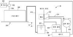
잉크젯 이미징 장치에 사용되는 종래 기술의 잉크 전달 시스템(20)이 도 6에 도시된다. 잉크 전달 시스템(20)은, 프린트헤드(608)에 연결되고 프린트헤드 아래에 위치되어 잉크 레벨이 프린트헤드 내의 잉크에 대해 적절한 배압(back pressure)을 제공하도록 프린트헤드 아래로 사전결정된 거리(D)에서 유지될 수 있는 잉크 공급 저장소(604)를 포함한다. 이러한 배압은 양호한 잉크 액적 방출 성능을 보장하는 데 도움을 준다. 잉크 저장소는 잉크를 거리(D)를 유지하는 레벨에서 유지시키는 잉크의 공급원(도시되지 않음)에 작동식으로 연결된다. 프린트헤드(608)는 매니폴드(manifold)를 갖고, 이는 잉크젯이 매니폴드로부터 잉크를 당길 때까지 잉크를 저장한다. 프린트헤드 매니폴드의 용량은 전형적으로 모든 잉크젯의 용량의 5배이다. 매니폴드의 입구는 도관(618)을 통해 잉크 저장소(604)에 연결되고, 도관(634)은 매니폴드의 출구를 폐 잉크 탱크(waste ink tank)(638)에 연결한다. 도관(634)을 선택적으로 차단하기 위해 도관(634) 내에 밸브(642)가 설치된다. 공기 압력 펌프(616)를 잉크 저장소(604)에 연결하는 밸브(612)가 또한 도관(614) 내에 제공되고, 이러한 밸브는 퍼징(purging) 작동 중일 때를 제외하고는 개방되어 유지된다.A prior art
새로운 프린트헤드가 설치되거나 그의 매니폴드가 도관(618) 내의 공기를 제거하기 위해 플러싱될(flushed) 필요가 있을 때, 매니폴드 퍼지가 수행된다. 매니폴드 퍼지 중에, 제어기(80)는 유체가 매니폴드 출구로부터 폐 잉크 탱크(638)로 유동하는 것을 가능하게 하도록 밸브(642)를 작동시키고, 공기 압력 펌프(616)를 활성화시키며, 잉크 저장소를 대기압에 대해 폐쇄하기 위해 밸브(612)를 작동시키고, 따라서 펌프(616)는 잉크 저장소(604) 내의 잉크를 가압할 수 있다. 가압된 잉크는 도관(618)을 통해 프린트헤드(608)의 매니폴드 입구로 유동한다. 밸브(642)가 또한 개방되기 때문에, 매니폴드로부터 잉크젯으로의 유체 유동에 대한 공압 임피던스(pneumatic impedance)가 매니폴드를 통한 공압 임피던스보다 크다. 따라서, 잉크는 매니폴드 출구로부터 폐 탱크로 유동한다. 압력 펌프(616)는 저장소 내의 잉크의 공급부를 완전히 소진시키지 않고서 도관(618), 프린트헤드(608) 내의 매니폴드, 및 도관(634)을 충전하기에 충분한 일정 체적의 잉크를 도관(618) 및 프린트헤드(608)의 매니폴드를 통해 밀어 내기 위해 사전결정된 기간 동안 사전결정된 압력으로 작동된다. 제어기는 이어서 도관(634)을 폐쇄하기 위해 밸브(642)를 작동시키고, 잉크 저장소를 대기압으로 통기시키기 위해 밸브(612)를 작동시킨다. 따라서, 매니폴드 퍼지가 잉크 저장소로부터 프린트헤드까지의 도관(618), 매니폴드, 및 도관(634)을 충전하고, 따라서 도관 또는 프린트헤드 내에 공기가 존재하지 않기 때문에 매니폴드 및 잉크 전달 시스템(20)이 프라이밍된다(primed). 잉크 저장소는 이어서 잉크의 높이를, 저장소 내의 레벨과 프린트헤드 잉크젯 사이의 거리가 이전에 언급된 바와 같이 D인 레벨로 되게 하도록 재공급된다.Manifold purging is performed when a new printhead is installed or its manifold needs to be flushed to remove air in
매니폴드 프라임 후에 프린트헤드(608) 내의 잉크젯을 프라이밍하기 위해, 제어기(80)는 밸브(612)를 폐쇄하고 공기 압력 펌프(616)를 활성화시켜 잉크를 프린트헤드에 보내기 위해 저장소(604)의 헤드 공간을 가압한다. 밸브(642)가 폐쇄되기 때문에, 매니폴드를 통한 프라이밍된 시스템의 공압 임피던스는 잉크젯을 통한 공압 임피던스보다 크고, 따라서 잉크가 잉크젯 내로 가압된다. 다시, 퍼지 압력은 잉크젯을 충전하기에 적절한 일정 체적의 잉크를 프린트헤드 내로 가압하기 위해 사전결정된 기간 동안 사전결정된 압력으로 가해진다. 잉크젯 내의 이전에 있던 임의의 잉크가 프린트헤드(608)의 면판(faceplate)(624) 내의 노즐로부터 방출된다. 이러한 잉크 퍼징은 잉크젯을 프라이밍하고, 또한 막히고 작동하지 않는 잉크젯을 그들의 작동 상태로 복원하는 데 도움을 줄 수 있다. 압력을 가한 후에, 제어기(80)는 밸브(612)를 작동시켜 개방하고 잉크 저장소로부터 압력을 해제시킨다. 압력 센서(620)가 또한 압력 공급 도관(622)에 작동식으로 연결되고, 이러한 센서는 저장소 내의 압력을 나타내는 신호를 생성한다. 이러한 신호는 공기 압력 펌프의 작동을 조정하기 위해 제어기(80)에 제공된다. 퍼징 중의 저장소 내의 압력이 사전결정된 임계치를 초과하면, 제어기(80)는 밸브(612)를 작동시켜 압력을 해제시킨다. 저장소 내의 압력이 퍼징 중에 사전결정된 임계치 미만으로 하락하면, 제어기(80)는 압력 공급원(616)을 작동시켜 압력을 상승시킨다. 2개의 사전결정된 임계치는 제어기가 저장소 내의 압력을 하나의 특정 압력보다는 퍼징 중에 사전결정된 범위로 유지시킬 수 있도록 상이하다.To prime the inkjet within the
일부 잉크젯 이미징 장치는 저 점도 상태로부터 고 점도 상태로 비교적 신속하게 변화하는 잉크를 사용한다. 인쇄 중에 밸브(612)가 개방되고 잉크 저장소(604)가 대기압에 있을 때, 각각의 비활성 잉크젯(inactive inkjet)의 노즐(630)에 있는 잉크 내의 메니스커스(meniscus)가 도 7에 도시된 형상을 갖게 된다. 인쇄 작업들 사이의 시간 또는 일부 잉크젯의 작동들 사이의 시간이 일정 지속기간을 초과할 때, 물과 같은 용제가 잉크로부터 증발한다. 이러한 증발은 도 7의 파선 원 내에 위치된 노즐의 에지에서 가장 신속하게 발생하는데, 이는 잉크가 이들 부분에서 가장 얇기 때문이다. 잉크의 점도가 이러한 증발로 인해 증가함에 따라, 잉크는 노즐(630)의 보어(bore)에 고착되기 시작하고, 잉크젯은 막히게 될 수 있다. 제어기(80)가 잉크젯으로부터 고 점도 잉크를 퍼징하고 새로운 잉크를 프린트헤드의 잉크젯 내로 제공하기 위해 퍼징 작동을 수행할 수 있더라도, 이러한 퍼징 작동은 달리 인쇄를 위해 이용가능한 잉크를 낭비할 수 있다. 신속하게 건조되는 잉크에 대한 빈번한 퍼징의 필요성을 감소시키는 것이 유리할 것이다.Some inkjet imaging devices use ink that changes relatively quickly from a low viscosity state to a high viscosity state. The shape shown in FIG. 7 is a meniscus in the ink in the
잉크젯 프린터 작동의 방법이 프린트헤드의 노즐에 있는 잉크가 저 점도 상태를 유지하는 것을 가능하게 한다. 방법은 제어기에 의해, 공기 압력 펌프와 프린트헤드에 연결된 잉크 저장소 사이에 작동식으로 연결되는 밸브를, 공기 압력 펌프를 잉크 저장소에 연결하기 위해 작동시키는 단계, 제어기에 의해, 프린트헤드 내의 비활성 잉크젯들에서 잉크 메니스커스를, 잉크 메니스커스를 파열시키지 않고서, 연장시키도록 잉크 저장소 내의 잉크에 압력을 인가하기 위해 공기 압력 펌프를 활성화시키는 단계, 및 제어기에 의해, 비활성 잉크젯들에서 잉크 메니스커스를 후퇴시키도록 공기 압력 펌프를 잉크 저장소로부터 분리하고 잉크 저장소를 대기압으로 통기시키기 위해 밸브를 작동시키는 단계를 포함한다.The method of inkjet printer operation enables the ink in the nozzle of the printhead to maintain a low viscosity state. The method comprises, by a controller, operating a valve operatively connected between the air pressure pump and the ink reservoir connected to the printhead to connect the air pressure pump to the ink reservoir, by the controller, inert inkjets in the printhead Activating an air pressure pump to apply pressure to the ink in the ink reservoir to extend the ink meniscus, without bursting the ink meniscus, and by the controller, the ink meniscus in inert inkjets And removing the air pressure pump from the ink reservoir to retract and operating the valve to vent the ink reservoir to atmospheric pressure.
잉크젯 프린터가 프린트헤드의 노즐에 있는 잉크가 저 점도 상태를 유지하는 것을 가능하게 하는 방법을 구현한다. 프린터는 프린트헤드, 프린트헤드에 작동식으로 연결되어 잉크를 프린트헤드에 제공하는 잉크 저장소, 잉크 저장소에 작동식으로 연결되는 공기 압력 펌프로서, 잉크 저장소 및 프린트헤드 내의 잉크에 압력을 인가하도록 구성되는, 공기 압력 펌프, 잉크 저장소와 공기 압력 펌프 사이에 작동식으로 연결되는 밸브로서, 잉크 저장소가 대기압으로 통기되는 제1 위치로 그리고 공기 압력 펌프가 잉크 저장소에 압력을 인가하는 제2 위치로 이동되도록 구성되는, 밸브, 및 밸브 및 공기 압력 펌프에 작동식으로 연결되는 제어기를 포함한다. 제어기는 프린트헤드 내의 비활성 잉크젯들에서 잉크 메니스커스를, 잉크 메니스커스를 파열시키지 않고서, 연장시키기에 충분한 압력을 인가하도록 공기 압력 펌프를 연결하기 위해 밸브를 작동시키도록 그리고 비활성 잉크젯들에서 잉크 메니스커스를 후퇴시키도록 공기 압력 펌프를 잉크 저장소로부터 분리하고 잉크 저장소를 대기압으로 통기시키기 위해 밸브를 작동시키도록 구성된다.The inkjet printer implements a method that enables the ink in the nozzle of the printhead to maintain a low viscosity state. The printer is a printhead, an ink reservoir operatively connected to the printhead to provide ink to the printhead, an air pressure pump operatively connected to the ink reservoir, configured to apply pressure to the ink reservoir and ink in the printhead , An air pressure pump, a valve operatively connected between the ink reservoir and the air pressure pump, so that the ink reservoir is moved to a first position where the ink reservoir is vented to atmospheric pressure and to a second position where the air pressure pump applies pressure to the ink reservoir It comprises a valve, and a controller operatively connected to the valve and the air pressure pump. The controller operates a valve to connect the air pressure pump to apply sufficient pressure to extend the ink meniscus in the inert inkjets in the printhead, without bursting the ink meniscus, and inks in the inert inkjets The air pressure pump is separated from the ink reservoir to retract the meniscus and is configured to operate the valve to vent the ink reservoir to atmospheric pressure.
도 1은 매체의 웨브(web)에 직접 잉크 이미지를 인쇄하는 그리고 프린터의 프린트헤드로부터의 속건성 잉크의 증발을 감소시키는 수성 잉크젯 프린터의 개략도.
도 2는 프린터의 프린트헤드로부터의 속건성 잉크의 증발을 감소시키기 위해 도 1에 도시된 프린터 내에 사용되는 잉크 전달 시스템의 개략도.
도 3은 프린터의 프린트헤드로부터의 속건성 잉크의 증발이 감소되도록 도 1 및 도 2의 프린터의 잉크 전달 시스템을 작동시키기 위한 프로세스의 흐름도.
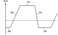
도 4는 도 3의 프로세스가 수행됨에 따른 잉크 저장소 내의 압력의 그래프.
도 5는 도 3의 프로세스 중에 압력이 상승될 때 프린트헤드의 노즐에서의 잉크 메니스커스를 예시한 도면.
도 6은 단지 퍼징을 위해 종래 기술의 프린터 내에 사용되는 종래 기술의 잉크 전달 시스템의 개략도.
도 7은 퍼징 작동 중일 때 외에 종래 기술의 프린트헤드 내의 비활성 잉크젯의 노즐에서의 잉크 메니스커스를 예시한 도면.1 is a schematic diagram of an aqueous inkjet printer that prints an ink image directly onto a web of media and reduces evaporation of fast drying ink from the printer's printhead.
2 is a schematic diagram of an ink delivery system used in the printer shown in FIG. 1 to reduce evaporation of quick-drying ink from the printer's printhead.
3 is a flow diagram of a process for operating the ink delivery system of the printers of FIGS. 1 and 2 such that evaporation of the fast drying ink from the printhead of the printer is reduced.
4 is a graph of pressure in the ink reservoir as the process of FIG. 3 is performed.
FIG. 5 illustrates the ink meniscus at the nozzle of the printhead as pressure rises during the process of FIG. 3.
6 is a schematic diagram of a prior art ink delivery system used in a prior art printer for purging only.
Figure 7 illustrates ink meniscus at a nozzle of an inert ink jet in a prior art printhead other than during a purging operation.
도 1은 제어기(80')가 프린트헤드(34A, 34B, 34C, 34D)의 노즐에 있는 잉크가 비활성 기간 중에 저 점도 상태를 유지하도록 잉크 전달 시스템(20')(도 2)을 작동시키기 위해 후술되는 프로세스(400)를 수행하도록 구성된 고속 수성 잉크 이미지 생성 기계 또는 프린터(10)를 예시한다. 예시된 바와 같이, 프린터(10)는 제어기(80')가 권취 롤(take up roll)(46)이 그것을 중심으로 장착된 샤프트(42)에 작동식으로 연결된 액추에이터(40) 중 하나를 작동시킴으로써 프린터(10)를 통해 당겨지는 매체의 웨브(W)의 표면 상에 잉크 이미지를 직접 형성하는 프린터이다. 일 실시예에서, 각각의 프린트헤드 모듈은 프린터에 의해 인쇄될 수 있는 프로세스-횡단(cross-process) 방향으로 가장 넓은 매체의 폭에 대응하는 폭을 갖는 단지 하나의 프린트헤드를 갖는다. 다른 실시예에서, 프린트헤드 모듈은, 각각의 프린트헤드가 프린터가 인쇄할 수 있는 프로세스-횡단 방향으로 가장 넓은 매체의 폭보다 작은 폭을 갖는 복수의 프린트헤드를 갖는다. 이들 모듈에서, 프린트헤드는 단일 프린트헤드보다 넓은 매체가 인쇄되는 것을 가능하게 하는 엇갈린 프린트헤드의 어레이로 배열된다. 추가적으로, 프린트헤드는 또한 프로세스-횡단 방향으로 프린트헤드에 의해 방출되는 액적의 밀도가 프로세스-횡단 방향으로 프린트헤드 내의 잉크젯들 사이의 최소 간격보다 클 수 있도록 인터레이싱될(interlaced) 수 있다.Figure 1 is for the controller 80' to operate the ink delivery system 20' (Figure 2) so that the ink at the nozzles of the
수성 잉크 전달 서브시스템(20')은 하나의 색상의 수성 잉크를 함유하는 적어도 하나의 잉크 저장소를 갖는다. 예시된 프린터(10)가 다색 이미지 생성 기계이기 때문에, 잉크 전달 시스템(20')은 4가지 상이한 색상(CYMK)(시안, 황색, 마젠타, 흑색)의 수성 잉크에 해당하는 4개의 잉크 저장소를 포함한다. 각각의 잉크 저장소는 프린트헤드 모듈 내의 프린트헤드 또는 프린트헤드들에 연결되어 모듈 내의 프린트헤드에 잉크를 공급한다. 퍼지 시스템(24)의 통기구(vent) 및 압력 공급원이 또한 프린트헤드로부터의 잉크의 증발을 감소시키기 위해, 프로세스(400)를 참조하여 후술되는 바와 같이, 프린트헤드 모듈 내의 프린트헤드와 잉크 저장소 사이에 작동식으로 연결된다. 추가적으로, 도 1에 도시되지 않지만, 프린트헤드 모듈 내의 각각의 프린트헤드는 전술된 매니폴드 및 잉크젯 퍼지 작동을 가능하게 하도록 도 6을 참조하여 전술된 바와 같은 밸브에 의해 대응하는 폐 잉크 탱크에 연결된다. 프린트헤드 모듈(34A 내지 34D)은 제어기(80')에 의한 하나 이상의 프린트헤드의 작동을 위한 관련 전자장치를 포함할 수 있지만, 그러한 연결은 도면을 간략화하기 위해 도시되지 않는다. 프린터(10)가 각각 프린트헤드의 2개의 어레이를 갖는 4개의 프린트헤드 모듈(34A 내지 34D)을 포함하지만, 대안적인 구성은 모듈 내에 상이한 개수의 프린트헤드 모듈 또는 어레이를 포함한다.The water-based ink delivery subsystem 20' has at least one ink reservoir containing one color of water-based ink. Since the illustrated
잉크 이미지가 웨브(W) 상에 인쇄된 후에, 이미지는 이미지 건조기(30) 아래로 통과한다. 이미지 건조기(30)는 잉크 이미지를 가열하고 이미지를 웨브에 적어도 부분적으로 정착시키기 위한 적외선 히터, 가열식 공기 송풍기, 공기 순환기(air return), 또는 이들 구성요소의 조합을 포함할 수 있다. 적외선 히터는 잉크 내의 물 또는 용제를 증발시키기 위해 웨브의 표면 상의 인쇄된 이미지에 적외선 열을 인가한다. 가열식 공기 송풍기는 잉크로부터의 물 또는 용제의 증발을 보완하도록 가열된 공기를 잉크 위로 지향시킨다. 공기는 이어서 프린터 내의 다른 구성요소와의 공기 유동의 간섭을 감소시키기 위해 공기 순환기에 의해 수집되어 배기된다.After the ink image is printed on the web W , the image passes under the
추가로 도시된 바와 같이, 매체 웨브(W)는 제어기(80')가 하나 이상의 액추에이터(40)를, 매체 롤이 샤프트(36)를 중심으로 회전함에 따라 매체 롤(38)로부터 웨브를 당기기 위해 권취 롤(46)이 그 상에 배치된 샤프트(42)를 회전시키도록 작동시킴으로써 필요한 대로 매체의 롤(38)로부터 풀린다. 웨브가 완전히 인쇄된 때, 권취 롤은 추가의 처리를 위해 샤프트(42)로부터 제거될 수 있다. 대안적으로, 인쇄된 웨브는 매체를 재단(cutting), 정합(collating), 제본(binding), 및 스테이플링(stapling)하는 것과 같은 작업을 수행하는 다른 처리 스테이션(도시되지 않음)으로 지향될 수 있다.As further shown, the media web W is used to pull the web from the media roll 38 as the controller 80' rotates one or
기계 또는 프린터(10)의 다양한 서브시스템, 구성요소 및 기능의 작동 및 제어는 제어기 또는 전자 서브시스템(ESS)(80')의 도움으로 수행된다. ESS 또는 제어기(80')는 잉크 전달 시스템(20'), 퍼지 시스템(24), 프린트헤드 모듈(34A 내지 34D)(및 그에 따른 프린트헤드), 액추에이터(40), 및 히터(30)의 구성요소에 작동가능하게 연결된다. ESS 또는 제어기(80')는 예를 들어 전자 데이터 저장장치를 가진 중앙 프로세서 유닛(CPU), 및 디스플레이 또는 사용자 인터페이스(UI)(50)를 갖는 독립형, 전용 미니-컴퓨터이다. ESS 또는 제어기(80')는 예를 들어 센서 입력 및 제어 회로뿐만 아니라 픽셀 배치 및 제어 회로를 포함한다. 또한, CPU는 이미지 입력 소스, 예컨대 스캐닝 시스템 또는 온라인 또는 워크 스테이션 접속과 프린트헤드 모듈(34A 내지 34D) 사이의 이미지 데이터 흐름을 판독, 캡처, 준비 및 관리한다. 이와 같이, ESS 또는 제어기(80')는 인쇄 프로세스를 포함하여 다른 기계 서브시스템 및 기능 모두를 작동시키고 제어하기 위한 주 멀티-태스킹 프로세서(main multi-tasking processor)이다.The operation and control of the various subsystems, components and functions of the machine or
제어기(80')는 프로그래밍된 명령어를 실행하는 범용 또는 특수 프로그램가능 프로세서로 구현될 수 있다. 프로그래밍된 기능을 수행하는 데 요구되는 명령어 및 데이터는 프로세서 또는 제어기와 관련된 메모리에 저장될 수 있다. 프로세서, 그들의 메모리, 및 인터페이스 회로는 후술되는 작동을 수행하도록 제어기를 구성한다. 이들 구성요소는 인쇄 회로 카드 상에 제공되거나 주문형 집적 회로(ASIC) 내의 회로로서 제공될 수 있다. 각각의 회로는 별개의 프로세서로 구현될 수 있거나, 다수의 회로가 동일한 프로세서 상에서 구현될 수 있다. 대안적으로, 회로는 초고밀도 집적(VLSI) 회로 내에 제공되는 개별 구성요소 또는 회로로 구현될 수 있다. 또한, 본 명세서에 기술된 회로는 프로세서, ASIC, 개별 구성요소, 또는 VLSI 회로의 조합으로 구현될 수 있다.The controller 80' can be implemented with a general purpose or special programmable processor that executes programmed instructions. Instructions and data required to perform the programmed function may be stored in memory associated with the processor or controller. The processor, their memory, and interface circuits configure the controller to perform the operations described below. These components may be provided on a printed circuit card or as circuitry in an application specific integrated circuit (ASIC). Each circuit can be implemented as a separate processor, or multiple circuits can be implemented on the same processor. Alternatively, the circuit can be implemented with individual components or circuits provided within a very high density integrated (VLSI) circuit. Further, the circuits described herein may be implemented as a processor, ASIC, individual components, or a combination of VLSI circuits.
작동 시에, 생성될 이미지를 위한 이미지 데이터가 프린트헤드 모듈(34A 내지 34D)로 출력되는 프린트헤드 제어 신호의 생성 및 처리를 위해 스캐닝 시스템 또는 온라인 또는 워크 스테이션 접속 중 어느 하나로부터 제어기(80')로 송신된다. 추가적으로, 제어기(80')는 예를 들어 사용자 인터페이스(50)를 통한 조작자 입력으로부터 관련 서브시스템 및 구성요소 제어를 결정 및 수용하고, 그에 따라 그러한 제어를 실행한다. 결과적으로, 적절한 색상을 위한 수성 잉크가 프린트헤드 모듈(34A 내지 34D)에 전달된다. 추가적으로, 이미지 데이터에 대응하는 잉크 이미지를 형성하기 위해 웨브의 표면에 대한 픽셀 배치 제어가 수행되고, 매체는 권취 롤 상에 감기거나 달리 처리될 수 있다.In operation, the controller 80' from either a scanning system or an online or workstation connection for generation and processing of printhead control signals where image data for the image to be generated is output to the
유사한 구성요소에 대해 유사한 도면 부호를 사용하여, 프린트헤드로부터의 신속하게 건조되는 잉크의 증발을 감소시킬 수 있는 잉크 전달 시스템이 도 2에 도시된다. 이러한 시스템(20')은 제어기(80')가 잉크 저장소(604)에 의해 공급되는 프린트헤드의 노즐에 있는 잉크가 건조되는 것을 감소시키기 위해 인쇄 작업 중에 그리고 인쇄 작업들 사이에 도 3에 도시된 프로세스(400)를 수행하도록 구성된다는 점에서 도 6에 도시된 시스템과 상이하다. 도 3은 노즐 내의 잉크의 점도를 그의 저 점도로 유지시키기 위해 프린트헤드(608) 내의 노즐에 있는 잉크의 메니스커스를 변동시키도록 잉크 전달 시스템(20')을 작동시키는 프로세스(400)에 대한 흐름도를 도시한다. 아래의 논의에서, 기능 또는 동작을 수행하는 프로세스(400)에 대한 언급은 프린터 내의 다른 구성요소와 관련하여 기능 또는 동작을 수행하도록 저장된 프로그램 명령어를 실행하는 제어기(80')와 같은 제어기의 작동을 지칭한다. 프로세스(400)는 예시적인 목적을 위해 도 1의 프린터(10) 내의 잉크 전달 시스템(20')에 의해 수행되는 것으로 기술된다.An ink delivery system is shown in FIG. 2 that can reduce evaporation of rapidly drying ink from the printhead, using similar reference numerals for similar components. This system 20' is shown in FIG. 3 during and between print jobs to reduce drying of the ink in the nozzle of the printhead by which the controller 80' is supplied by the
인쇄 작동 중에, 잉크 전달 시스템(20') 및 프린트헤드(608)는 완전히 프라이밍되는데, 이는 잉크가 폐 탱크와 프린트헤드의 매니폴드 출구 사이의 도관을 충전하고, 프린트헤드의 매니폴드 및 잉크젯이 잉크로 가득 차며, 매니폴드 입구와 잉크 저장소 사이의 도관(618)이 잉크로 가득 찬 것을 의미한다. 프린터(10)가 비활성 기간에 진입하려 하거나 프린트헤드(608) 내의 잉크젯이 노즐에 있는 잉크를 보다 높은 점도로 되게 할 수 있는 기간 동안 비활성이었을 때, 프로세스(400)가 수행된다. 프로세스는 제어기가 잉크 저장소 내의 압력이 대기압에 있는지를 검증하는 것으로 시작한다(블록(404)). 제어기는 밸브(612)의 상태를 검사함으로써 또는 센서(620)로부터의 신호를 기준 대기압과 비교함으로써 이러한 검증을 수행할 수 있다. 프로세스는 이어서 공기 압력 펌프(616)를 잉크 저장소(604)에 연결하기 위해 밸브(612)를 작동시킨다(블록(408)). 이들 2개의 블록의 처리가 수행될 때, 잉크 저장소 내의 압력은 도 4에 도시된 그래프의 세그먼트(504)에 의해 표현되고, 비활성 잉크젯에 있는 수성 잉크의 메니스커스는 도 7에 도시된 바와 같이 나타난다. 프로세스는 제어기(80')가 공기 압력 펌프를 잉크 저장소(604) 내의 잉크에 양(positive)의 공기 압력을 인가하도록 작동시키는 것으로 계속된다(블록(412)). 제어기는 이어서 압력이 사전결정된 임계치에 도달할 때까지 센서(620)로부터의 신호를 모니터링한다(블록(416)). 따라서, 잉크 저장소 내의 압력은 그것이 도 4의 그래프에서 세그먼트(508)에 의해 표시된 바와 같이 임계치에 도달할 때까지 변화한다. 이러한 압력에서, 프린트헤드 내의 비활성 노즐에 있는 수성 잉크의 잉크 메니스커스는 도 5에 도시된 바와 같이 나타난다. 사전결정된 임계치에 대응하는 압력은 메니스커스를 노즐 개구(630)를 지나 연장시키기에 충분하지만, 압력은 메니스커스를 파열시키기에는 충분하지 않다. 일 실시예에서, 그러한 압력은 약 ?? psi 내지 약 ?? psi의 범위 내에 있지만, 범위는 예를 들어 잉크 저장소와 프린트헤드를 연결하는 튜브의 직경, 잉크 저장소에 연결되는 프린트헤드의 개수, 잉크 저장소 및 프린트헤드 내의 잉크 매니폴드의 크기, 및 프린트헤드 또는 프린트헤드들 내의 잉크젯의 개수와 같은 다수의 인자에 의존한다. 제어기(80')는 사전결정된 기간 동안 대기하고(wait)(블록(420)), 이어서 잉크 저장소(604)를 다시 대기(atmosphere)에 연결하기 위해 밸브를 작동시킨다(블록(424)). 사전결정된 기간의 지속기간은 잉크 메니스커스에서 잉크 내에 용제를 보충하는 것을 돕기 위해 새로운 잉크가 노즐 개구(630)에 도달하는 것을 가능하게 하기에 충분할 필요가 있다. 일 실시예에서, 사전결정된 기간은 약 msec 내지 약 msec의 범위 내에 있지만, 역시 기간의 길이는 예를 들어 프린트헤드 구성 및 관련 인자에 의존한다. 압력이 일단 밸브가 개방되면 도 4의 세그먼트(516)에 의해 도시된 바와 같이 하락하기 시작할 때까지, 압력이 도 4의 그래프에서 세그먼트(512)에 의해 표시된 바와 같이 사전결정된 압력으로 유지된다. 제어기(80'')는, 도 4의 세그먼트(520)에 의해 표시된 바와 같이, 잉크 저장소(604) 내의 압력이 대기압으로 복귀하고 사전결정된 기간 동안 대기압에서 유지되는지를 검증하기 위해 압력 센서로부터의 신호를 모니터링한다(블록(428)). 블록(408 내지 428)의 처리는 프린트헤드(624) 내의 비활성 잉크젯에서 메니스커스를 변동시키기 위해 사전결정된 횟수로 반복된다. 일 실시예에서, 사이클을 수행하기 위한 사전결정된 횟수는 약 X회 내지 약 Y회이지만, 횟수는 예를 들어 잉크의 점도, 반복되는 사이클의 수행 사이의 시간 등과 같은 다양한 인자에 의존한다. 메니스커스의 변동은 노즐(630)에 있는 잉크 내에 용제를 보충하고, 이는 노즐에서의 잉크 증발의 양을 감소시킨다. 따라서, 퍼지가 덜 빈번하게 필요하게 되며, 잉크가 잉크젯 재생보다는 인쇄를 위해 보존된다.During the printing operation, the ink delivery system 20' and
도 4의 프로세스가 비활성 노즐의 노즐에 있는 수성 잉크에서 발생하는 증발 문제를 해결하는 것으로 기술되었지만, 프로세스는 또한 UV 경화성 잉크와 같은 노즐에서 볼록한 메니스커스를 나타내는 잉크에 적용될 수 있다. UV 경화성 잉크의 볼록한 메니스커스는 예를 들어 그들이 프린터 내에 존재할 수 있는 UV 방사선의 존재 시에 비교적 정지한 상태로 유지되는 경우에 부분적으로 경화될 수 있다. 비활성 잉크젯에 있는 잉크의 메니스커스를 변동시키기 위해 UV 잉크 저장소에 대해 도 4의 프로세스를 수행하는 것은 노즐 개구에 있는 잉크를 재생함으로써 유사한 효과를 갖는다. 이러한 작용은 노즐에 있는 잉크의 부분적 경화를 미연에 방지하고, 잉크젯의 작동 능력을 보존한다.Although the process of FIG. 4 has been described to solve the evaporation problem arising from the water-based ink in the nozzle of the inert nozzle, the process can also be applied to ink exhibiting convex meniscus in nozzles such as UV curable ink. The convex meniscus of UV curable inks can be partially cured, for example if they remain relatively stationary in the presence of UV radiation that may be present in the printer. Performing the process of FIG. 4 on the UV ink reservoir to vary the meniscus of the ink in the inert inkjet has a similar effect by regenerating the ink in the nozzle opening. This action prevents partial curing of the ink in the nozzle and preserves the operating ability of the inkjet.
도 2는 잉크를 단일 프린트헤드에 공급하도록 구성된 하나의 잉크 전달 시스템(20')을 도시한다. 그러한 실시예에서, 잉크 전달 시스템은 프린터 내의 각각의 프린트헤드에 제공될 수 있다. 다른 실시예에서, 잉크 전달 시스템(20')은 다수의 프린트헤드에 동일 색상의 잉크를 공급하도록 구성될 수 있다. 따라서, 하나의 잉크 전달 시스템이 프린트헤드 모듈(34A, 34B, 34C, 34D) 중 하나 내의 모든 프린트헤드에 잉크를 공급하도록 구성될 수 있거나, 다수의 잉크 전달 시스템이 일대일 대응으로 프린트헤드 모듈 내의 상이한 프린트헤드에 잉크를 공급하도록 구성될 수 있다. 잉크 전달 시스템은 비활성 잉크젯에서 메니스커스를 변동시켜 그러한 잉크젯이 그들의 노즐에서 고 점도 잉크로 막히게 되지 않도록 인쇄 작업 중에 작동된다. 변동하는 메니스커스는 인쇄 작업 중에 인쇄를 위해 사용되고 있는 잉크젯에서의 잉크 액적의 방출과 간섭되지 않는다. 인쇄 작업들 사이 또는 비활성 기간 중에, 잉크 전달 시스템(20')은 노즐에서의 증발을 감소시키고 잉크젯의 작동 능력을 보존하기 위해 노즐에서 잉크 메니스커스를 변동시키도록 프로세스(400)를 계속 수행한다.Figure 2 shows one ink delivery system 20' configured to supply ink to a single printhead. In such an embodiment, an ink delivery system may be provided for each printhead in the printer. In other embodiments, the ink delivery system 20' may be configured to supply ink of the same color to multiple printheads. Thus, one ink delivery system can be configured to supply ink to all of the printheads in one of the
Claims (20)
프린트헤드(printhead);
상기 프린트헤드에 작동식으로 연결되어 잉크를 상기 프린트헤드에 제공하는 잉크 저장소;
상기 잉크 저장소에 작동식으로 연결되는 공기 압력 펌프로서, 상기 잉크 저장소 및 상기 프린트헤드 내의 잉크에 압력을 인가하도록 구성되는, 상기 공기 압력 펌프;
상기 잉크 저장소와 상기 공기 압력 펌프 사이에 작동식으로 연결되는 밸브로서, 상기 잉크 저장소가 대기압으로 통기되는 제1 위치로 그리고 상기 공기 압력 펌프가 상기 잉크 저장소에 압력을 인가하는 제2 위치로 이동되도록 구성되는, 상기 밸브; 및
상기 밸브 및 상기 공기 압력 펌프에 작동식으로 연결되는 제어기로서, 상기 프린트헤드 내의 비활성 잉크젯들(inactive inkjets)에서 잉크 메니스커스(ink meniscus)를, 상기 잉크 메니스커스를 파열시키지 않고서, 연장시키기에 충분한 압력을 인가하도록 상기 공기 압력 펌프를 연결하기 위해 상기 밸브를 작동시키도록 그리고 상기 비활성 잉크젯들에서 상기 잉크 메니스커스를 후퇴시키도록 상기 공기 압력 펌프를 상기 잉크 저장소로부터 분리하고 상기 잉크 저장소를 대기압으로 통기시키기 위해 상기 밸브를 작동시키도록 구성되는, 상기 제어기를 포함하는, 잉크 전달 시스템.An ink delivery system in a printer,
A printhead;
An ink reservoir operatively connected to the printhead to provide ink to the printhead;
An air pressure pump operatively connected to the ink reservoir, the air pressure pump being configured to apply pressure to the ink reservoir and ink in the printhead;
A valve that is operatively connected between the ink reservoir and the air pressure pump, such that the ink reservoir is moved to a first position at atmospheric pressure and to the second position where the air pressure pump applies pressure to the ink reservoir. Configured, the valve; And
A controller operatively connected to the valve and the air pressure pump, to extend ink meniscus in inactive inkjets in the printhead, without bursting the ink meniscus Disconnect the air pressure pump from the ink reservoir and operate the valve to connect the air pressure pump to apply sufficient pressure to it and retract the ink meniscus in the inert ink jets and remove the ink reservoir. An ink delivery system, comprising the controller, configured to operate the valve to vent to atmospheric pressure.
상기 잉크 저장소에 작동식으로 연결되는 센서로서, 상기 잉크 저장소 내의 압력을 나타내는 신호를 생성하도록 구성되는, 상기 센서를 추가로 포함하고,
상기 제어기는 상기 센서에 의해 생성되는 상기 신호를 수신하도록 상기 센서에 작동식으로 연결되고, 상기 제어기는 상기 센서로부터의 상기 신호에 의해 지시된 상기 압력을 기준 대기압과 비교하도록 추가로 구성되고, 상기 센서로부터의 상기 신호에 의해 지시된 상기 압력이 상기 기준 대기압에 대응할 때까지 상기 공기 압력 펌프를 상기 잉크 저장소에 연결하기 위해 상기 밸브를 작동시키는 것을 대기하는(waiting), 잉크 전달 시스템.The method of claim 5,
A sensor operatively connected to the ink reservoir, further comprising the sensor, configured to generate a signal indicative of pressure in the ink reservoir,
The controller is operatively connected to the sensor to receive the signal generated by the sensor, and the controller is further configured to compare the pressure indicated by the signal from the sensor to a reference atmospheric pressure, the An ink delivery system, waiting to operate the valve to connect the air pressure pump to the ink reservoir until the pressure indicated by the signal from the sensor corresponds to the reference atmospheric pressure.
제어기에 의해, 공기 압력 펌프와 프린트헤드에 연결된 잉크 저장소 사이에 작동식으로 연결되는 밸브를, 상기 공기 압력 펌프를 상기 잉크 저장소에 연결하기 위해 작동시키는 단계;
상기 제어기에 의해, 상기 프린트헤드 내의 비활성 잉크젯들에서 잉크 메니스커스를, 상기 잉크 메니스커스를 파열시키지 않고서, 연장시키도록 상기 잉크 저장소 내의 잉크에 압력을 인가하기 위해 상기 공기 압력 펌프를 활성화시키는 단계; 및
상기 제어기에 의해, 상기 비활성 잉크젯들에서 상기 잉크 메니스커스를 후퇴시키도록 상기 공기 압력 펌프를 상기 잉크 저장소로부터 분리하고 상기 잉크 저장소를 대기압으로 통기시키기 위해 상기 밸브를 작동시키는 단계를 포함하는, 방법.A method for reducing evaporation of ink from printheads in a printer,
Operating, by a controller, a valve operatively connected between the air pressure pump and the ink reservoir connected to the printhead to connect the air pressure pump to the ink reservoir;
By the controller to activate the air pressure pump to apply pressure to the ink in the ink reservoir to extend the ink meniscus in inert inkjets in the printhead, without bursting the ink meniscus step; And
And by the controller, removing the air pressure pump from the ink reservoir to retract the ink meniscus in the inert inkjets and operating the valve to vent the ink reservoir to atmospheric pressure. .
상기 제어기에 의해, 사전결정된 압력을 상기 잉크 저장소에 인가하기 위해 상기 공기 압력 펌프를 작동시키는 단계를 추가로 포함하는, 방법.The method of claim 11,
And, by the controller, operating the air pressure pump to apply a predetermined pressure to the ink reservoir.
상기 제어기에 의해, 상기 공기 압력 펌프를 상기 잉크 저장소에 연결된 상태로 유지하기 위해 상기 밸브를 작동시키면서 상기 공기 압력 펌프를 비활성화시키는 단계를 추가로 포함하는, 방법.The method of claim 12,
And further comprising, by the controller, activating the valve to deactivate the air pressure pump to keep the air pressure pump connected to the ink reservoir.
상기 제어기에 의해, 상기 공기 압력 펌프를 상기 잉크 저장소로부터 분리하고 상기 잉크 저장소를 대기압에 연결하기 위해 상기 밸브를 작동시키는 단계를 추가로 포함하는, 방법.The method of claim 13,
Further comprising, by the controller, actuating the valve to disconnect the air pressure pump from the ink reservoir and connect the ink reservoir to atmospheric pressure.
상기 잉크 저장소에 작동식으로 연결되는 센서에 의해, 상기 잉크 저장소 내의 압력을 나타내는 신호를 생성하는 단계;
상기 제어기에 의해, 상기 센서로부터의 상기 신호에 의해 지시된 상기 압력을 기준 대기압과 비교하는 단계; 및
상기 제어기에 의해, 상기 제어기가 상기 센서로부터의 상기 신호에 의해 지시된 상기 압력이 상기 기준 대기압에 대응하는 것으로 결정할 때 상기 공기 압력 펌프를 상기 잉크 저장소에 연결하기 위해 상기 밸브를 작동시키는 단계를 추가로 포함하는, 방법.The method of claim 15,
Generating, by a sensor operatively connected to the ink reservoir, a signal indicative of the pressure in the ink reservoir;
Comparing, by the controller, the pressure indicated by the signal from the sensor to a reference atmospheric pressure; And
Adding, by the controller, actuating the valve to connect the air pressure pump to the ink reservoir when the controller determines that the pressure indicated by the signal from the sensor corresponds to the reference atmospheric pressure. Included with, method.
상기 제어기에 의해, 상기 센서로부터의 상기 신호에 의해 지시된 상기 압력이 상기 사전결정된 압력에 대응할 때 상기 공기 압력 펌프를 비활성화시키는 단계를 추가로 포함하는, 방법.The method of claim 16,
And by the controller, deactivating the air pressure pump when the pressure indicated by the signal from the sensor corresponds to the predetermined pressure.
상기 제어기에 의해, 상기 공기 압력 펌프를 상기 잉크 저장소에 재연결하기 위해 상기 밸브를 작동시키는 단계; 및
상기 제어기에 의해, 상기 센서로부터의 상기 신호가 상기 기준 대기압에 대응할 때로부터 다른 사전결정된 기간이 만료된 후에 상기 공기 압력 펌프를 활성화시키는 단계를 추가로 포함하는, 방법.The method of claim 17,
Operating, by the controller, the valve to reconnect the air pressure pump to the ink reservoir; And
And by the controller, activating the air pressure pump after another predetermined period has expired from when the signal from the sensor corresponds to the reference atmospheric pressure.
상기 제어기에 의해, 상기 프린트헤드 내의 상기 비활성 잉크젯들의 노즐들에서 상기 잉크 메니스커스를 연장시키도록 상기 잉크 저장소에 압력을 인가하고 상기 프린트헤드 내의 상기 비활성 잉크젯들의 상기 노즐들에서 상기 잉크 메니스커스를 후퇴시키도록 상기 인가된 압력을 대기로 해제시키는 사이클을 사전결정된 횟수로 반복하는 단계를 추가로 포함하는, 방법.The method of claim 18,
By the controller, applying pressure to the ink reservoir to extend the ink meniscus at nozzles of the inactive inkjets in the printhead and the ink meniscus at the nozzles of the inactive inkjets in the printhead. And repeating the cycle of releasing the applied pressure to the atmosphere to retreat a predetermined number of times.
Applications Claiming Priority (2)
| Application Number | Priority Date | Filing Date | Title |
|---|---|---|---|
| US16/215,806 | 2018-12-11 | ||
| US16/215,806 US10518551B1 (en) | 2018-12-11 | 2018-12-11 | System and method for attenuating the drying of ink from a printhead |
Publications (2)
| Publication Number | Publication Date |
|---|---|
| KR20200071663A true KR20200071663A (en) | 2020-06-19 |
| KR102557513B1 KR102557513B1 (en) | 2023-07-19 |
Family
ID=69057484
Family Applications (1)
| Application Number | Title | Priority Date | Filing Date |
|---|---|---|---|
| KR1020190153118A Active KR102557513B1 (en) | 2018-12-11 | 2019-11-26 | System and method for attenuating the drying of ink from a printhead |
Country Status (4)
| Country | Link |
|---|---|
| US (1) | US10518551B1 (en) |
| JP (1) | JP7308129B2 (en) |
| KR (1) | KR102557513B1 (en) |
| CN (1) | CN111300989B (en) |
Cited By (1)
| Publication number | Priority date | Publication date | Assignee | Title |
|---|---|---|---|---|
| KR20200071003A (en) | 2018-12-10 | 2020-06-18 | 제록스 코포레이션 | System and method for attenuating the drying of ink from a printhead during idle periods |
Families Citing this family (2)
| Publication number | Priority date | Publication date | Assignee | Title |
|---|---|---|---|---|
| CN111559173B (en) * | 2019-02-13 | 2022-10-21 | 精工爱普生株式会社 | Liquid ejection device |
| US12496173B2 (en) * | 2020-11-17 | 2025-12-16 | James R. Glidewell Dental Ceramics, Inc. | Method for coloring a dental prosthesis |
Citations (5)
| Publication number | Priority date | Publication date | Assignee | Title |
|---|---|---|---|---|
| KR20060100267A (en) * | 2005-03-15 | 2006-09-20 | 제록스 코포레이션 | Inkjet device |
| US20110267406A1 (en) | 2010-04-29 | 2011-11-03 | Hanson Spencer R | Liquid Delivery For A Printhead |
| KR20120118437A (en) * | 2011-04-18 | 2012-10-26 | 제록스 코포레이션 | Using low pressure assist(lpa) to enable printhead maintenance system simplification |
| KR101397307B1 (en) * | 2013-07-22 | 2014-05-23 | 부경대학교 산학협력단 | Device and method for precise meniscus pressure control of printer |
| JP2014208441A (en) * | 2013-03-22 | 2014-11-06 | キヤノンファインテック株式会社 | Liquid discharge head and liquid discharge device |
Family Cites Families (26)
| Publication number | Priority date | Publication date | Assignee | Title |
|---|---|---|---|---|
| JPS55158974A (en) | 1979-05-26 | 1980-12-10 | Ricoh Co Ltd | Choking detector in ink jet printer and remover thereof |
| JPS5627935U (en) | 1979-08-13 | 1981-03-16 | ||
| JPS63221047A (en) | 1987-03-11 | 1988-09-14 | Sharp Corp | Nozzle clogging preventive device of ink jet printer |
| US5394178A (en) | 1992-12-21 | 1995-02-28 | Hewlett-Packard Company | Printhead servicing apparatus with pivotal servicing lever |
| US5635965A (en) | 1995-01-31 | 1997-06-03 | Hewlett-Packard Company | Wet capping system for inkjet printheads |
| US5936647A (en) | 1996-10-31 | 1999-08-10 | Hewlett-Packard Company | Flexible frame onsert capping of inkjet printheads |
| US5980622A (en) | 1997-08-29 | 1999-11-09 | Hewlett-Packard Company | Magenta dyes for ink-jet inks |
| US6814423B2 (en) | 2002-06-18 | 2004-11-09 | Hewlett-Packard Development Company, L.P. | Capping system for a printhead |
| US7156514B2 (en) | 2004-04-30 | 2007-01-02 | Lexmark International, Inc. | Inks and printheads with internal clog prevention |
| US7258416B2 (en) | 2004-12-06 | 2007-08-21 | Silverbrook Research Pty Ltd | Inkjet printer with pivotal capping member |
| EP1827839B1 (en) | 2004-12-06 | 2009-02-18 | Silverbrook Research Pty. Ltd | Two-stage capping mechanism for inkjet printers |
| US7637602B2 (en) | 2006-03-03 | 2009-12-29 | Silverbrook Research Pty Ltd | Printer with ink flow shutoff valve |
| JPWO2008026417A1 (en) | 2006-09-01 | 2010-01-14 | コニカミノルタエムジー株式会社 | Replacement liquid for inkjet printer, inkjet image recording method, and inkjet printer |
| US20080204501A1 (en) | 2006-12-01 | 2008-08-28 | Shinichi Kurita | Inkjet print head pressure regulator |
| US7992986B2 (en) | 2008-03-17 | 2011-08-09 | Xerox Corporation | Method for increasing printhead reliability |
| US8172348B2 (en) | 2008-03-24 | 2012-05-08 | Hewlett-Packard Development Company, L.P. | Print head cap vent |
| JP5282575B2 (en) | 2009-01-05 | 2013-09-04 | 株式会社リコー | Image forming apparatus |
| US8517510B2 (en) | 2009-07-24 | 2013-08-27 | Hewlett-Packard Development Company, L. P. | Fluid dispensing apparatus and method thereof |
| JP2011201231A (en) | 2010-03-26 | 2011-10-13 | Dainippon Screen Mfg Co Ltd | Recorder |
| US8926059B2 (en) | 2010-10-27 | 2015-01-06 | Hewlett-Packard Development Company, L.P. | Print head capping device and printer |
| US8592503B2 (en) | 2012-03-29 | 2013-11-26 | Funai Electric Co., Ltd. | Aqueous magenta inkjet ink composition containing a mixture of a self-dispersed pigment and a xanthene dye |
| JP5898116B2 (en) | 2013-03-15 | 2016-04-06 | 富士フイルム株式会社 | Abnormality detection method for pressure sensor and liquid ejection device |
| CN104290455B (en) * | 2013-07-18 | 2016-08-10 | 北大方正集团有限公司 | An ink supply device and a method for forming a meniscus on the surface of a printing ink head |
| JP6389386B2 (en) * | 2014-07-16 | 2018-09-12 | 株式会社Screenホールディングス | Control method for liquid ejection device and liquid ejection device |
| JP6547759B2 (en) | 2014-12-09 | 2019-07-24 | コニカミノルタ株式会社 | Ink supply device and inkjet recording device |
| KR101937349B1 (en) * | 2016-10-27 | 2019-01-10 | 세메스 주식회사 | Apparatus for Supplying Droplet Formation and Apparatus for Droplet Formation having the same |
-
2018
- 2018-12-11 US US16/215,806 patent/US10518551B1/en active Active
-
2019
- 2019-11-14 CN CN201911111213.0A patent/CN111300989B/en active Active
- 2019-11-20 JP JP2019209435A patent/JP7308129B2/en active Active
- 2019-11-26 KR KR1020190153118A patent/KR102557513B1/en active Active
Patent Citations (5)
| Publication number | Priority date | Publication date | Assignee | Title |
|---|---|---|---|---|
| KR20060100267A (en) * | 2005-03-15 | 2006-09-20 | 제록스 코포레이션 | Inkjet device |
| US20110267406A1 (en) | 2010-04-29 | 2011-11-03 | Hanson Spencer R | Liquid Delivery For A Printhead |
| KR20120118437A (en) * | 2011-04-18 | 2012-10-26 | 제록스 코포레이션 | Using low pressure assist(lpa) to enable printhead maintenance system simplification |
| JP2014208441A (en) * | 2013-03-22 | 2014-11-06 | キヤノンファインテック株式会社 | Liquid discharge head and liquid discharge device |
| KR101397307B1 (en) * | 2013-07-22 | 2014-05-23 | 부경대학교 산학협력단 | Device and method for precise meniscus pressure control of printer |
Cited By (1)
| Publication number | Priority date | Publication date | Assignee | Title |
|---|---|---|---|---|
| KR20200071003A (en) | 2018-12-10 | 2020-06-18 | 제록스 코포레이션 | System and method for attenuating the drying of ink from a printhead during idle periods |
Also Published As
| Publication number | Publication date |
|---|---|
| CN111300989A (en) | 2020-06-19 |
| KR102557513B1 (en) | 2023-07-19 |
| CN111300989B (en) | 2022-12-30 |
| JP2020093537A (en) | 2020-06-18 |
| US10518551B1 (en) | 2019-12-31 |
| JP7308129B2 (en) | 2023-07-13 |
Similar Documents
| Publication | Publication Date | Title |
|---|---|---|
| US7971984B2 (en) | Systems and methods for varying dye concentrations | |
| KR102557513B1 (en) | System and method for attenuating the drying of ink from a printhead | |
| KR101946194B1 (en) | Printer and method for operating a printer | |
| KR101810251B1 (en) | Using low pressure assist(lpa) to enable printhead maintenance system simplification | |
| US20070229588A1 (en) | Liquid ejection apparatus and maintenance method for liquid ejection head | |
| KR102694627B1 (en) | System and method to counteract the drying of aqueous inks in a printhead | |
| US9545794B2 (en) | Selective purging of ink jets to limit purge mass | |
| US10518537B1 (en) | System and method for attenuating the drying of ink from a printhead | |
| CN111284138B (en) | System and method for mitigating drying of ink from a printhead during idle periods | |
| US10828901B1 (en) | Printhead cap for attenuating the drying of ink from a printhead during periods of printer inactivity | |
| KR102278130B1 (en) | Fluid Recirculation Technique in the Printhead | |
| JP7465728B2 (en) | Printhead cap for attenuating drying of ink from the printhead during periods of press inactivity | |
| US10933641B2 (en) | Method for attenuating the drying of ink from a printhead during periods of printhead inactivity | |
| US10889117B2 (en) | System and method for attenuating the drying of ink from a printhead during periods of printer inactivity | |
| US11383525B2 (en) | System and method for efficiently purging printheads | |
| US10562308B1 (en) | System and method for priming an ink delivery system in an inkjet printer |
Legal Events
| Date | Code | Title | Description |
|---|---|---|---|
| PA0109 | Patent application |
Patent event code: PA01091R01D Comment text: Patent Application Patent event date: 20191126 |
|
| PG1501 | Laying open of application | ||
| A201 | Request for examination | ||
| A302 | Request for accelerated examination | ||
| PA0201 | Request for examination |
Patent event code: PA02012R01D Patent event date: 20221121 Comment text: Request for Examination of Application Patent event code: PA02011R01I Patent event date: 20191126 Comment text: Patent Application |
|
| PA0302 | Request for accelerated examination |
Patent event date: 20221121 Patent event code: PA03022R01D Comment text: Request for Accelerated Examination Patent event date: 20191126 Patent event code: PA03021R01I Comment text: Patent Application |
|
| E902 | Notification of reason for refusal | ||
| PE0902 | Notice of grounds for rejection |
Comment text: Notification of reason for refusal Patent event date: 20230316 Patent event code: PE09021S01D |
|
| E701 | Decision to grant or registration of patent right | ||
| PE0701 | Decision of registration |
Patent event code: PE07011S01D Comment text: Decision to Grant Registration Patent event date: 20230526 |
|
| GRNT | Written decision to grant | ||
| PR0701 | Registration of establishment |
Comment text: Registration of Establishment Patent event date: 20230717 Patent event code: PR07011E01D |
|
| PR1002 | Payment of registration fee |
Payment date: 20230717 End annual number: 3 Start annual number: 1 |
|
| PG1601 | Publication of registration |