KR20200071092A - Goods handling device for erecting a carton - Google Patents
Goods handling device for erecting a carton Download PDFInfo
- Publication number
- KR20200071092A KR20200071092A KR1020207013277A KR20207013277A KR20200071092A KR 20200071092 A KR20200071092 A KR 20200071092A KR 1020207013277 A KR1020207013277 A KR 1020207013277A KR 20207013277 A KR20207013277 A KR 20207013277A KR 20200071092 A KR20200071092 A KR 20200071092A
- Authority
- KR
- South Korea
- Prior art keywords
- hub
- rims
- shaft
- tool head
- longitudinal axis
- Prior art date
Links
- 230000008878 coupling Effects 0.000 claims abstract description 29
- 238000010168 coupling process Methods 0.000 claims abstract description 29
- 238000005859 coupling reaction Methods 0.000 claims abstract description 29
- 238000004806 packaging method and process Methods 0.000 claims description 25
- 238000000034 method Methods 0.000 claims description 16
- 239000000969 carrier Substances 0.000 claims description 4
- 230000001360 synchronised effect Effects 0.000 claims description 4
- 238000011144 upstream manufacturing Methods 0.000 description 5
- 239000000463 material Substances 0.000 description 3
- 230000013011 mating Effects 0.000 description 3
- 230000000694 effects Effects 0.000 description 2
- 241001272720 Medialuna californiensis Species 0.000 description 1
- 230000001154 acute effect Effects 0.000 description 1
- 230000007613 environmental effect Effects 0.000 description 1
- 238000012946 outsourcing Methods 0.000 description 1
- 238000000926 separation method Methods 0.000 description 1
- 239000000758 substrate Substances 0.000 description 1
- 239000002699 waste material Substances 0.000 description 1
Images


Classifications
-
- B—PERFORMING OPERATIONS; TRANSPORTING
- B31—MAKING ARTICLES OF PAPER, CARDBOARD OR MATERIAL WORKED IN A MANNER ANALOGOUS TO PAPER; WORKING PAPER, CARDBOARD OR MATERIAL WORKED IN A MANNER ANALOGOUS TO PAPER
- B31B—MAKING CONTAINERS OF PAPER, CARDBOARD OR MATERIAL WORKED IN A MANNER ANALOGOUS TO PAPER
- B31B50/00—Making rigid or semi-rigid containers, e.g. boxes or cartons
- B31B50/74—Auxiliary operations
- B31B50/76—Opening and distending flattened articles
- B31B50/80—Pneumatically
- B31B50/804—Pneumatically using two or more suction devices on a rotating element
-
- B—PERFORMING OPERATIONS; TRANSPORTING
- B31—MAKING ARTICLES OF PAPER, CARDBOARD OR MATERIAL WORKED IN A MANNER ANALOGOUS TO PAPER; WORKING PAPER, CARDBOARD OR MATERIAL WORKED IN A MANNER ANALOGOUS TO PAPER
- B31B—MAKING CONTAINERS OF PAPER, CARDBOARD OR MATERIAL WORKED IN A MANNER ANALOGOUS TO PAPER
- B31B50/00—Making rigid or semi-rigid containers, e.g. boxes or cartons
- B31B50/02—Feeding or positioning sheets, blanks or webs
- B31B50/10—Feeding or positioning webs
- B31B50/102—Feeding or positioning webs using rolls, belts or chains
-
- B—PERFORMING OPERATIONS; TRANSPORTING
- B31—MAKING ARTICLES OF PAPER, CARDBOARD OR MATERIAL WORKED IN A MANNER ANALOGOUS TO PAPER; WORKING PAPER, CARDBOARD OR MATERIAL WORKED IN A MANNER ANALOGOUS TO PAPER
- B31B—MAKING CONTAINERS OF PAPER, CARDBOARD OR MATERIAL WORKED IN A MANNER ANALOGOUS TO PAPER
- B31B50/00—Making rigid or semi-rigid containers, e.g. boxes or cartons
- B31B50/26—Folding sheets, blanks or webs
-
- B—PERFORMING OPERATIONS; TRANSPORTING
- B31—MAKING ARTICLES OF PAPER, CARDBOARD OR MATERIAL WORKED IN A MANNER ANALOGOUS TO PAPER; WORKING PAPER, CARDBOARD OR MATERIAL WORKED IN A MANNER ANALOGOUS TO PAPER
- B31B—MAKING CONTAINERS OF PAPER, CARDBOARD OR MATERIAL WORKED IN A MANNER ANALOGOUS TO PAPER
- B31B2100/00—Rigid or semi-rigid containers made by folding single-piece sheets, blanks or webs
- B31B2100/002—Rigid or semi-rigid containers made by folding single-piece sheets, blanks or webs characterised by the shape of the blank from which they are formed
- B31B2100/0022—Rigid or semi-rigid containers made by folding single-piece sheets, blanks or webs characterised by the shape of the blank from which they are formed made from tubular webs or blanks, including by tube or bottom forming operations
-
- B—PERFORMING OPERATIONS; TRANSPORTING
- B31—MAKING ARTICLES OF PAPER, CARDBOARD OR MATERIAL WORKED IN A MANNER ANALOGOUS TO PAPER; WORKING PAPER, CARDBOARD OR MATERIAL WORKED IN A MANNER ANALOGOUS TO PAPER
- B31B—MAKING CONTAINERS OF PAPER, CARDBOARD OR MATERIAL WORKED IN A MANNER ANALOGOUS TO PAPER
- B31B2110/00—Shape of rigid or semi-rigid containers
- B31B2110/30—Shape of rigid or semi-rigid containers having a polygonal cross section
- B31B2110/35—Shape of rigid or semi-rigid containers having a polygonal cross section rectangular, e.g. square
-
- B—PERFORMING OPERATIONS; TRANSPORTING
- B31—MAKING ARTICLES OF PAPER, CARDBOARD OR MATERIAL WORKED IN A MANNER ANALOGOUS TO PAPER; WORKING PAPER, CARDBOARD OR MATERIAL WORKED IN A MANNER ANALOGOUS TO PAPER
- B31B—MAKING CONTAINERS OF PAPER, CARDBOARD OR MATERIAL WORKED IN A MANNER ANALOGOUS TO PAPER
- B31B2120/00—Construction of rigid or semi-rigid containers
- B31B2120/30—Construction of rigid or semi-rigid containers collapsible; temporarily collapsed during manufacturing
- B31B2120/302—Construction of rigid or semi-rigid containers collapsible; temporarily collapsed during manufacturing collapsible into a flat condition
Abstract
평평하게 접힌 캐리어를 세우기 위한 장치로서, 종축을 갖는 샤프트(46)를 포함한다. 이 샤프트에는 허브(27)가 장착된다. 상기 허브에는 피봇 커플링에 의해 하나 이상의 림(16a-16c)이 회전식으로 장착된다. 상기 림에는 공구 헤드(14a-14c)가 장착된다. 상기 샤프트에는 허브를 상기 종축 방향에 대해 회전시키기 위한 구동 모터가 결합된다. 상기 장치는 상기 공구 헤드와 상기 종축 사이의 거리가 조정될 수 있도록 상기 하나 이상의 림을 상기 허브에 대해 회전시키기 위한 제1 구동 메커니즘을 포함한다.A device for erecting a flat folded carrier, comprising a shaft (46) with a longitudinal axis. The hub 27 is mounted on this shaft. The hub is pivotally mounted with one or more rims 16a-16c by pivot coupling. The rim is equipped with tool heads 14a-14c. A drive motor for rotating the hub about the longitudinal axis is coupled to the shaft. The device includes a first drive mechanism for rotating the one or more rims relative to the hub so that the distance between the tool head and the longitudinal axis can be adjusted.
Description
본 발명은 물품을 취급하기 위한 장치를 제공한다. 특히, 배타적이지는 않지만, 상기 장치는 편평한 접을 수 있는 카톤 블랭크를 세워서 관형 구조체를 형성하기 위해 사용될 수 있다. 본 발명의 양태들은 물품 취급 장치를 채용하는 카톤 직립 스테이션을 포함하는 포장기에 관한 것이다.The present invention provides an apparatus for handling an article. In particular, although not exclusively, the device can be used to form a flat foldable carton blank to form a tubular structure. Aspects of the invention relate to a packaging machine comprising a carton upright station employing an article handling device.
포장 분야에서는 다수의 물품을 운반하기 위한 카톤을 제공하는 것이 알려져있다. 카톤은 당 업계에 잘 알려져 있으며 소비자가 소비할 한 그룹의 물품을 운송, 저장 및 접근할 수 있게 하는 데 유용하다. 비용 및 환경적 고려를 위해, 그러한 카톤 또는 캐리어는 가능한 한 적은 재료로 형성될 필요가 있고 가능한 한 재료에서 적은 낭비를 야기해야 한다. 추가 고려 사항은 카톤의 강도 및 큰 중량의 물품을 보유 및 운송하기 위한 적합성이다. 카톤 또는 캐리어의 내용물이 카톤 내에 안전하게 보관되는 것이 바람직하다.It is known in the field of packaging to provide a carton for carrying a large number of articles. Cartons are well known in the art and are useful for enabling consumers to transport, store and access a group of items for consumption. For cost and environmental considerations, such a carton or carrier needs to be formed of as little material as possible and should cause as little waste in the material as possible. Additional considerations are the strength of the carton and its suitability for holding and transporting large items of weight. It is preferred that the contents of the carton or carrier are safely stored in the carton.
미리 접착되거나 미리 접혀지는 편평한 접을 수 있는 구조로서 그러한 카톤을 제공하는 것이 알려져 있다. 이러한 편평한 접힌 구조는 그 다음에, 포장 기계에서, 하나 이상의 물품을 수용하기 위한 내부 챔버를 가진 직립된 카톤 또는 캐리어로 조립될 수 있다. 상이한 설계 및 구조의 그리고 상이한 상대적 배열의 패널들을 가진 카톤 블랭크를 단일 장치를 사용하여 세울 수 있는 것이 바람직하다.It is known to provide such a carton as a flat collapsible structure that is pre-bonded or pre-folded. This flat folded structure can then be assembled into an upright carton or carrier with an inner chamber for receiving one or more items, in a packaging machine. It is desirable that carton blanks of panels of different designs and structures and with different relative arrangements can be built using a single device.
본 발명은 복수의 상이한 구성들의 카톤을 세우는 데 적합한 단일 장치를, 보다 구체적으로는 최종 적재 포장 기계들에서의 그 사용을 제공함으로써 종래 기술의 문제점을 극복하거나 적어도 완화하고자 한다.The present invention seeks to overcome or at least alleviate the problems of the prior art by providing a single device suitable for erecting a carton of a plurality of different configurations, more specifically its use in final loading packaging machines.
또한, 상기 장치가 통합되는 포장 기계의 크기를 감소시키기 위해 소규모 카톤 직립 장치를 제공하는 것이 바람직하다.It is also desirable to provide a small carton upright device to reduce the size of the packaging machine in which the device is incorporated.
본 개시의 제1 양태는 편평하게 접힌 캐리어를 세우기 위한 장치를 제공하며, 이 장치는 종축(longitudinal axis)을 가진 샤프트(shaft)를 포함한다. 상기 샤프트에는 허브(hub)가 장착된다. 상기 허브에는 하나 이상의 림(limb)이 피봇 커플링(pivot coupling)에 의해 회전식으로 장착된다. 상기 림에는 공구 헤드(tool head)가 장착될 수 있다. 상기 종축을 중심으로 상기 허브를 회전시키기 위해 구동 모터가 상기 샤프트에 장착된다. 상기 장치는 상기 공구 헤드와 상기 종축 사이의 거리가 조절될 수 있도록 상기 허브에 대하여 상기 하나 이상의 림을 회전시키기 위한 제1 구동 메커니즘을 포함한다. A first aspect of the present disclosure provides a device for erecting a flat folded carrier, the device comprising a shaft with a longitudinal axis. The shaft is equipped with a hub. One or more limbs are pivotally mounted to the hub by pivot coupling. A tool head may be mounted on the rim. A drive motor is mounted on the shaft to rotate the hub about the longitudinal axis. The device includes a first drive mechanism for rotating the one or more rims relative to the hub so that the distance between the tool head and the longitudinal axis can be adjusted.
선택적으로, 상기 공구 헤드는 상기 하나 이상의 림에 회전 가능하게 장착되며, 사용 시 상기 공구 헤드는 상기 허브가 종축을 중심으로 회전할 때 일정한 배향(orientation)을 유지하도록 회전 구동된다.Optionally, the tool head is rotatably mounted to the one or more rims, and in use, the tool head is rotationally driven to maintain a constant orientation when the hub rotates about its longitudinal axis.
선택적으로, 상기 구동 모터는 제2 구동 메커니즘에 의해 상기 공구 헤드에 결합된다.Optionally, the drive motor is coupled to the tool head by a second drive mechanism.
선택적으로, 상기 제2 구동 메커니즘은 다음을 포함한다:Optionally, the second drive mechanism includes:
상기 피봇 커플링에 장착된 일차 스프로킷(sprocket);A primary sprocket mounted on the pivot coupling;
상기 피봇 커플링에 장착되고 상기 일차 스프로킷과 동기를 이루는 동심 스프로킷;A concentric sprocket mounted on the pivot coupling and synchronized with the primary sprocket;
상기 하나 이상의 림에 회전식으로 장착되고 상기 공구 헤드가 장착된 된 이차 스프로킷;A secondary sprocket rotatably mounted on the one or more rims and equipped with the tool head;
상기 일차 스프로킷에 장착되고 회전 구동 기계에 결합된 일차 구동 벨트;A primary drive belt mounted on the primary sprocket and coupled to a rotary drive machine;
상기 동심 스프로킷을 상기 이차 스프로킷에 결합하는 이차 구동 벨트.A secondary drive belt coupling the concentric sprocket to the secondary sprocket.
선택적으로, 상기 구동 모터는 상기 회전 구동 기계를 형성한다.Optionally, the drive motor forms the rotation drive machine.
선택적으로, 추가 구동 모터가 상기 회전 구동 기계를 형성한다.Optionally, an additional drive motor forms the rotation drive machine.
선택적으로, 상기 제1 구동 메커니즘은 다음을 포함한다:Optionally, the first drive mechanism includes:
상기 샤프트에 장착되고 상기 허브에 대해 회전 가능한 제1 톱니 바퀴;A first cogwheel mounted on the shaft and rotatable relative to the hub;
상기 피봇 커플링을 중심으로 상기 하나 이상의 림에 고정 장착된 제2 톱니 바퀴;A second cogwheel fixedly mounted to the one or more rims around the pivot coupling;
상기 허브에 대한 상기 제1 톱니 바퀴의 회전을 제어하기 위해 상기 제1 톱니 바퀴에 결합된 액추에이터.An actuator coupled to the first cogwheel to control rotation of the first cogwheel relative to the hub.
본 개시의 제2 양태는 편평하게 접힌 캐리어로부터 관형 캐리어 구조체를 세우기 위한 카톤 직립 장치를 제공한다. 상기 장치는 종축을 갖는 샤프트를 포함한다. 상기 샤프트에 허브가 장착된다. 상기 장치는 복수의 림을 포함하고, 각각 은 피봇 커플링에 의해 상기 허브에 회전식으로 장착된다. 상기 복수의 림 각각에는 공구 헤드가 장착될 수 있다. 상기 종축에 대해 상기 허브를 회전시키기 위한 구동 모터가 상기 샤프트에 결합된다. 상기 장치는 상기 공구 헤드와 상기 종축 사이의 거리가 조정될 수 있도록 상기 허브에 대해 상기 복수의 림 각각을 회전시키기 위한 제1 구동 메커니즘을 포함한다. A second aspect of the present disclosure provides a carton upright device for erecting a tubular carrier structure from a flat folded carrier. The device comprises a shaft with a longitudinal axis. A hub is mounted on the shaft. The device includes a plurality of rims, each of which is rotatably mounted to the hub by pivot coupling. Each of the plurality of rims may be equipped with a tool head. A drive motor for rotating the hub about the longitudinal axis is coupled to the shaft. The device includes a first drive mechanism for rotating each of the plurality of rims relative to the hub so that the distance between the tool head and the longitudinal axis can be adjusted.
선택적으로, 상기 구동 메커니즘은 상기 허브에 대해 상기 복수의 림 각각을 동시에 회전시킨다.Optionally, the drive mechanism simultaneously rotates each of the plurality of rims relative to the hub.
선택적으로, 각각의 공구 헤드는 상기 복수의 림 각각에 회전 가능하게 장착되며, 사용 시에 상기 공구 헤드는 상기 허브가 상기 종축을 중심으로 회전될 때 일정한 배향을 유지하도록 회전 구동된다.Optionally, each tool head is rotatably mounted to each of the plurality of rims, and in use, the tool head is rotationally driven to maintain a constant orientation when the hub is rotated about the longitudinal axis.
선택적으로, 상기 구동 모터는 제2 구동 메커니즘에 의해 상기 공구 헤드들의 각각에 결합된다.Optionally, the drive motor is coupled to each of the tool heads by a second drive mechanism.
선택적으로, 상기 제2 구동 메커니즘은 다음을 포함한다:Optionally, the second drive mechanism includes:
상기 피봇 커플링 각각에 장착된 일차 스프로킷;A primary sprocket mounted to each of the pivot couplings;
상기 피봇 커플링 각각에 장착되고 각각의 일차 스프로킷과 동기하는 동심 스프로킷;A concentric sprocket mounted on each of the pivot couplings and synchronized with each primary sprocket;
상기 복수의 림 각각에 회전식으로 장착되고 각각의 공구 헤드들이 장착된 이차 스프로킷;A secondary sprocket rotatably mounted to each of the plurality of rims and equipped with respective tool heads;
상기 일차 스프로킷에 장착되고 회전 구동 기계에 결합된 일차 구동 벨트;A primary drive belt mounted on the primary sprocket and coupled to a rotary drive machine;
상기 동심 스프로킷을 상기 이차 스프로킷에 결합하는 이차 구동 벨트.A secondary drive belt coupling the concentric sprocket to the secondary sprocket.
선택적으로, 상기 구동 모터는 상기 회전 구동 기계를 형성한다.Optionally, the drive motor forms the rotation drive machine.
선택적으로, 추가 구동 모터가 상기 회전 구동 기계를 형성한다.Optionally, an additional drive motor forms the rotation drive machine.
선택적으로, 상기 제1 구동 메커니즘은 다음을 포함한다:Optionally, the first drive mechanism includes:
상기 샤프트에 장착되고 상기 허브에 대해 회전 가능한 제1 톱니 바퀴;A first cogwheel mounted on the shaft and rotatable relative to the hub;
상기 각각의 피봇 커플링 주위에서 상기 복수의 림 각각에 고정 장착된 제2 톱니 바퀴;A second cogwheel fixedly mounted to each of the plurality of rims around each pivot coupling;
상기 허브에 대한 상기 제1 톱니 바퀴의 회전을 제어하기 위해 상기 제1 톱니 바퀴에 결합된 액추에이터. An actuator coupled to the first cogwheel to control rotation of the first cogwheel relative to the hub.
본 개시의 제3 양태는 물품을 이송하기 위한 물품 취급 장치를 제공한다. 상기 장치는 종축을 갖는 샤프트를 포함한다. 상기 샤프트에 허브가 장착된다. 상기 장치는 피봇 커플링에 의해 상기 허브에 각각 회전식으로 장착된 복수의 림을 포함한다. 상기 복수의 림 각각에 공구 헤드가 장착될 수 있다. 상기 허브를 상기 종축에 대해 회전시키기 위한 구동 모터가 상기 샤프트에 결합된다. 상기 장치는 상기 공구 헤드와 상기 종축 사이의 거리가 조정될 수 있도록 상기 허브에 대하여 상기 복수의 림 각각을 회전시키기 위한 제1 구동 메커니즘를 포함한다.A third aspect of the present disclosure provides an article handling apparatus for conveying articles. The device comprises a shaft with a longitudinal axis. A hub is mounted on the shaft. The device includes a plurality of rims each rotatably mounted to the hub by pivot coupling. A tool head may be mounted on each of the plurality of rims. A drive motor for rotating the hub about the longitudinal axis is coupled to the shaft. The device includes a first drive mechanism for rotating each of the plurality of rims relative to the hub so that the distance between the tool head and the longitudinal axis can be adjusted.
본 개시의 제4 양태는 물품을 맞물기 위한 물품 취급 장치를 제공하며, 상기 장치는 다음을 포함한다: A fourth aspect of the present disclosure provides an article handling apparatus for engaging an article, the apparatus including:
종축을 갖는 샤프트;A shaft having a longitudinal axis;
상기 샤프트에 장착된 허브;A hub mounted on the shaft;
피봇 커플링에 의해 상기 허브에 각각 회전식으로 장착된 복수의 림;A plurality of rims each rotatably mounted to the hub by pivot coupling;
상기 복수의 림 각각에 장착된 공구 헤드;A tool head mounted on each of the plurality of rims;
상기 종축을 중심으로 상기 허브를 회전시키기 위해 상기 샤프트에 결합된 구동 모터;A drive motor coupled to the shaft to rotate the hub about the longitudinal axis;
상기 공구 헤드의 도달 거리가 조정될 수 있도록 상기 허브에 대해 상기 복수의 림 각각을 회전시키기 위한 제1 구동 메커니즘.A first drive mechanism for rotating each of the plurality of rims relative to the hub so that the reach of the tool head can be adjusted.
본 개시의 제5 양태는 물품을 포장하기 위한 포장 기계를 제공한다. 상기 포장 기계는 편평하게 접힌 캐리어들의 입력 스트림을 이송하기 위한 컨베이어와, 상기 컨베이어에 의해 운반되는 동안 편평하게 접힌 캐리어를 순차적으로 맞물도록 배열된 카톤 직립 장치를 포함하는 직립 스테이션을 포함한다. 상기 카톤 직립 장치는 편평하게 접힌 캐리어를 관형 캐리어 구조체로 세운다. 상기 카톤 직립 장치는 종축을 갖는 샤프트를 포함한다. 상기 샤프트에 허브가 장착된다. 상기 카톤 직립 장치는 복수의 림을 포함하며, 각각은 피봇 커플링에 의해 상기 허브에 회전식으로 장착된다. 상기 복수의 림 각각에 공구 헤드가 장착될 수 있다. 상기 허브를 상기 종축에 대해 회전시키기 위해 구동 모터가 상기 샤프트에 결합된다. 상기 카톤 직립 장치는 상기 공구 헤드와 상기 종축 사이의 거리가 조절될 수 있도록 상기 허브에 대하여 상기 복수의 림 각각을 회전시키기 위한 제1 구동 메커니즘을 포함한다.A fifth aspect of the present disclosure provides a packaging machine for packaging an article. The packaging machine comprises an upright station comprising a conveyor for conveying an input stream of flat folded carriers and a carton upright device arranged to sequentially engage flat folded carriers while being carried by the conveyor. The carton upright device erects a flat folded carrier into a tubular carrier structure. The carton upright device comprises a shaft having a longitudinal axis. A hub is mounted on the shaft. The carton upright device includes a plurality of rims, each of which is rotatably mounted to the hub by pivot coupling. A tool head may be mounted on each of the plurality of rims. A drive motor is coupled to the shaft to rotate the hub about the longitudinal axis. The carton upright device includes a first drive mechanism for rotating each of the plurality of rims relative to the hub so that the distance between the tool head and the longitudinal axis can be adjusted.
선택적으로, 상기 카톤 직립 장치는 편평하게 접힌 캐리어를 세우며, 여기서 편평하게 접힌 상태의 경우 상기 캐리어의 제1 패널은 상기 캐리어의 제2 대향 패널과 정합(in registry with)하지 않는다. 카톤 직립 장치는 상기 제1 패널과 맞물려 제2 패널과 정합하여 세워진 캐리어 구조를 형성한다.Optionally, the carton upright device erects a flat folded carrier, in which case the first panel of the carrier does not mate with the second opposite panel of the carrier in the flat folded state. The carton upright device is engaged with the first panel to form a carrier structure erected to match the second panel.
선택적으로, 상기 공구 헤드는 상기 림에 회전 가능하게 장착되며, 사용 시에 상기 공구 헤드는 상기 허브가 상기 종축을 중심으로 회전될 때 상기 컨베이어에 대해 일정한 배향을 유지하도록 회전 구동된다.Optionally, the tool head is rotatably mounted to the rim, and in use, the tool head is rotationally driven to maintain a constant orientation with respect to the conveyor when the hub is rotated about the longitudinal axis.
본 출원의 범위 내에서, 선행 단락에서, 청구 범위에서 및/또는 상세한 설명 및 도면에서 제시된 다양한 양태, 실시 예, 예시, 특징 및 대안은 독립적으로 또는 이것들의 임의의 조합으로 취해질 수 있을 것으로 예상된다. 예를 들어, 일 실시 예와 관련하여 설명된 특징은 특징의 호환성이 없지 않다면 모든 실시 예에 적용 가능하다.Within the scope of this application, it is contemplated that various aspects, embodiments, examples, features, and alternatives set forth in the preceding paragraph, in the claims, and/or in the detailed description and drawings may be taken independently or in any combination thereof. . For example, features described in connection with one embodiment are applicable to all embodiments unless features are compatible.
이제 본 발명의 실시 예가 첨부 도면을 참조하여 설명될 것이다.
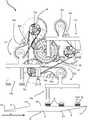
도 1은 본 개시의 일 실시 예에 따른 카톤 직립 장치의 사시도;
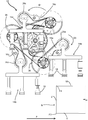
도 2는 도 1의 카톤 직립 장치의 평면도;
도 3은 도 1의 카톤 직립 장치의 저면도;
도 4는 도 1의 카톤 직립 장치의 제1 측면도;
도 5는 도 1의 카톤 직립 장치의 제2 측면도이고, 여기서 카톤 직립 장치는 제1 펼쳐친 상태에 있으며;
도 6 내지 9는 도 1의 카톤 직립 장치의 제2 측면도이고, 여기서 카톤 직립 장치는 카톤을 세우는 여러 단계에서 제2 움츠린 상태에 있다. Now, embodiments of the present invention will be described with reference to the accompanying drawings.
1 is a perspective view of a carton upright apparatus according to an embodiment of the present disclosure;
Figure 2 is a plan view of the carton upright device of Figure 1;
3 is a bottom view of the carton upright device of FIG. 1;
4 is a first side view of the carton upright device of FIG. 1;
5 is a second side view of the carton upright device of FIG. 1, wherein the carton upright device is in the first unfolded state;
6 to 9 are second side views of the carton upright device of FIG. 1, wherein the carton upright device is in a second crimp state at various stages of erecting the carton.
장치, 포장 기계 및 방법의 구체적인 실시 예의 상세한 설명이 개시된다. 개시된 실시 예는 단지 본 발명의 특정 측면이 구현될 수 있는 방식의 예일 뿐이며 본 발명이 구체화될 수 있는 모든 방식의 전체 목록을 나타내지는 않는다는 것이 이해될 것이다. 본 명세서에서 사용된 바와 같이, "예시적인"이라는 단어는 예시, 표본, 모델 또는 패턴으로 역할을 하는 실시 예를 지칭하기 위해 광범위하게 사용된다. 실제로, 본 명세서에 기술된 장치, 포장 기계 및 방법은 다양하고 대안적인 형태로 구현될 수 있음을 이해할 것이다. 도면은 반드시 축척대로 도시된 것은 아니며, 특정 구성 요소의 세부 사항을 나타내기 위해 일부 특징이 과장되거나 최소화될 수 있다. 공지된 구성 요소, 재료 또는 방법이 본 개시 내용을 모호하게 하는 것을 피하기 위해 반드시 상세하게 설명되지는 않는다. 본 명세서에 개시된 임의의 특정 구조적 및 기능적 세부 사항은 제한적인 것으로 해석되어서는 안 되고, 단지 청구 범위에 대한 기초로서 및 통상의 기술자가 본 발명을 다양하게 사용하도록 가르치기 위한 대표적인 기초로서 해석되어야 한다.Detailed description of specific embodiments of devices, packaging machines and methods are disclosed. It will be understood that the disclosed embodiments are merely examples of how certain aspects of the invention may be implemented and do not represent a complete list of all the ways in which the invention may be embodied. As used herein, the word "exemplary" is used extensively to refer to an example, serving as an example, sample, model, or pattern. Indeed, it will be understood that the devices, packaging machines and methods described herein can be implemented in a variety of alternative forms. The drawings are not necessarily drawn to scale, and some features may be exaggerated or minimized to show details of particular components. Known components, materials, or methods are not necessarily described in detail to avoid obscuring the present disclosure. Any specific structural and functional details disclosed herein should not be construed as limiting, but merely as a basis for the claims and as a representative basis for teaching a person skilled in the art to use the present invention in various ways.
도 1은 카톤을 편평하게 접힌 구성으로부터 관형 구조체로 세울 수 있는 카톤 직립 장치(10)의 형태를 취하는 물품 취급 장치를 도시한다.1 shows an article handling device taking the form of a carton
대안으로, 상기 물품 취급 장치는 물품을 한 위치에서 다른 위치로, 한정하는 것은 아니지만 예를 들어 한 높이에서 다른 높이로 집어서 배치하는 물품 조작 장치로서 채용될 수 있는 것이 생각된다.Alternatively, it is contemplated that the article handling device may be employed as an article handling device that does not limit the article from one location to another, but for example picks and places from one height to another.
카톤 직립 장치(10)는 샤프트(46)를 포함하고; 샤프트(46)는 종축('a')을 포함하며 이를 중심으로 샤프트(46)가 회전한다. 샤프트(46)는 샤프트(46)의 회전 운동을 제공하기 위해, 예컨대, 서보 모터와 같은 구동 수단(도시되지 않음)에 결합된다.The carton
일부 실시 예에서, 카톤 직립 장치(10)는 컨베이어(도시되지 않음) 위에 장착되며 샤프트(46)는 프레임(도시되지 않음), 또는 포장 기계의 일부를 형성하는 다른 적절한 섀시에 회전식으로 장착될 수 있다. 샤프트(46)를 프레임에 결합하기 위해 하나 이상의 베어링이 제공될 수 있다. In some embodiments, the carton
샤프트(46)는 실질적으로 수평으로 배향되며, 상기 종축('a')이 컨베이어 상의 카톤의 이동 방향에 대해 횡 방향 또는 직각이 되도록 배열될 수 있다.The
카톤 직립 장치(10)는 샤프트(46)에 장착된 허브(27)를 포함한다. 도시된 실시 예는 "Y" 형상으로 배열된 세 개의 아암(27a, 27b, 27c)을 포함하는 세 갈래로 찢어진 허브(27)를 포함하며, 상기 아암들은 서로 120 °떨어져 있다.The carton
카톤 직립 장치(10)는 복수의 하부 아암(forearm)(16a, 16b, 16c)을 포함하며; 하부 아암(16a, 16b, 16c) 각각은 허브(27)의 아암(27a, 27b, 27c)에 각각 결합된다. The carton
다른 실시 예에서, 상기 허브(27)는 다른 형태를 취할 수 있고, 더 적거나 많은 아암(27a, 27b, 27c)을 포함할 수 있으며, 아암(27a, 27b, 27c)은 생략될 수도 있으며, 허브(27)는 예를 들어 다각형 또는 원형일 수 있지만 이에 한정되지 않으며; 하부 아암(16a, 16b, 16c)은 상기 허브에 그 둘레를 따라 부착될 수 있고, 하부 아암(16a, 16b, 16c)은 서로 동일한 거리가 되도록 이격될 수 있다. In other embodiments, the
하부 아암(16a, 16b, 16c)의 각각은 각각의 커플링(70a, 70b, 70c)을 중심으로 피봇 회전할 수 있도록 각각의 아암(27a, 27b, 27c)에 결합된다(도 5 참조). Each of the
하부 아암(16a, 16b, 16c)은 도 6에 도시된 움츠린 위치와 도 5에 도시된 펼쳐진 위치 사이에서 움직일 수 있다.The
카톤 직립 장치(10)는 하부 아암(16a, 16b, 16c)의 각각에 결합된 공구 헤드(14a, 14b, 14c)를 포함한다. 공구 헤드(14a, 14b, 14c)는 각각 진공 흡입 컵 형태의 적어도 하나의 그리퍼(gripper) 장치(18)를 포함한다. 도시된 실시 예는 공구 헤드(14a, 14b, 14c) 당 3개의 흡입 컵을 포함한다. 카톤 직립 장치(10)는 진공 시스템을 포함하며, 그 요소들(50)이 도면들에 도시되어 있지만; 튜브 또는 호스는 편의상 생략되었다.The carton
공구 헤드(14a, 14b, 14c)는 각각 하부 아암(16a, 16b, 16c)에 회전식으로 결합된다.The tool heads 14a, 14b, 14c are rotatably coupled to the
허브(27)에 대한 하부 아암(16a, 16b, 16c) 각각의 배향을 제어하기 위한 제1 구동 시스템이 제공된다. 도 5에서 하부 아암(16a, 16b, 16c)은 허브(27)의 아암(27a, 27b, 27c)과 실질적으로 정렬된다. 도 5에서 하부 아암(16a, 16b, 16c)은 허브(27)의 아암(27a, 27b, 27c)과 실질적으로 동일선 상에 있다. 도 5에서 하부 아암(16a, 16b, 16c)은 허브(27)로부터 방사상으로 연장되도록 배열된다. 도 6에서 하부 아암(16a, 16b, 16c)은 그들 각각의 아암(27a, 27b, 27c)과 함께 예각을 형성하여 접히거나 움츠린 위치에 있도록 배열된다.A first drive system is provided for controlling the orientation of each of the
제1 구동 시스템은 허브(27)에 대해 회전할 수 있도록 샤프트(46)에 장착된 제1 기어 또는 톱니 바퀴(40)를 포함한다. 액추에이터 또는 구동 메커니즘(미도시)이 제1 기어(40)에 결합된다. 상기 구동 메커니즘 허브(27)에 대해 제1 기어(40)를 회전시키기 위해 제공된다. 예를 들면 상기 구동 메커니즘은 서보 모터 또는 스테퍼 모터와 같은 모터의 형태를 취할 수 있지만 이에 한정되지 않는다. 일부 실시 예에서, 상기 구동 메커니즘은 제1 기어(40)에 결합된 수동 액추에이터 또는 조절기를 포함할 수 있고, 상기 수동 액추에이터는 핸드 휠(hand wheel) 또는 크랭크 핸들(crank handle)의 형태를 취할 수 있고, 조작자는 상기 수동 액추에이터를 회전시켜서 하부 아암(16a, 16b, 16c)을 펼치거나 움츠릴 수 있다. 하부 아암(16a, 16b, 16c) 각각은 허브(27)와 하부 아암(16a, 16b, 16c)의 각각의 하나 사이의 커플링(70a, 70b, 70c)에 대하여 장착된 제2 기어 또는 톱니 바퀴(35, 36, 38)를 포함한다. 제2 기어 또는 톱니 바퀴(35, 36, 38)는 하부 아암(16a, 16b, 16c)의 각각의 하나에 고정된다. 이러한 방식으로, 허브(27)에 대한 제1 기어(40)의 회전은 커플링(70a, 70b, 70c)을 중심으로 하부 아암(16a, 16b, 16c)의 각각을 회전시키는 효과를 갖는다. 하부 아암(16a, 16b, 16c)은 제1 기어(40)의 회전에 응답하여 허브(27)에 대해서 함께 또는 동시에 회전된다. 이러한 방식으로, 하부 아암(16a, 16b, 16c)은 움츠린 위치와 펼쳐진 위치 사이에서 움직일 수 있다. The first drive system includes a first gear or
대안의 실시 예에서, 하부 아암(16a, 16b, 16c)은, 제1 단부에서 하부 아암(16a) 중 하나에 피봇식으로 결합되고 제2 대향 단부에서 허브(27)의 하부 아암(16a, 16b, 16c)에 결합된 피스톤 및 실린더 장치와 같은 선형 액추에이터에 의해 펼쳐진 위치와 움츠린 위치 사이에서 이동될 수 있다.In an alternative embodiment, the
선택적으로, 제2 기어(35, 36, 38)는 허브(27)에 대한 하부 아암(16a, 16b, 16c)의 왕복 회전에 적응된 부분 기어이다. 제2 기어(35, 36, 38)는 0°와 180° 사이의 각도에서 하부 아암(16a, 16b, 16c) 각각을 회전시키도록 배열될 수 있다. 도시된 실시 예에서, 제2 기어(35, 36, 38)는 150°내지 160°범위의 최대 각도까지의 회전 각도에 걸쳐 하부 아암(16a, 16b, 16c ) 각각을 회전시키도록 배열된다. 실제로, 하부 아암(16a, 16b, 16c)은 110°내지 120°범위의 최대 각도까지 회전 각도에 걸쳐 회전될 수 있으며, 이는 제2 기어가 제1 기어(40)로부터 분리될 가능성을 회피하거나 감소시킨다. 다른 실시 예들에서, 이것은 제1 기어(40)와 유사한 완전한 기어 휠을 제공함으로써 회피될 수 있다. Optionally, the
최대 회전 각도를 제한하는 것은 또한 공구 헤드(14a, 14b, 14c) 사이의 자기 충돌, 즉 공구 헤드(14a, 14b, 14c) 중 하나와 공구 헤드(14a, 14b, 14c) 중 다른 하나의 충돌을 완화할 수도 있다; 또한 하부 아암(16a, 16b, 16c) 사이의 자기 충돌을 대해 완화할 수도 있다. 다른 실시 예에서, 이것은, 하부 아암(16a, 16b, 16c)(그리고 결과적으로 공구 헤드(14a, 14b, 14c))이 180°이상의 최대 각도로 회전할 수 있도록, 하부 아암(16a, 16b, 16c)의 길이에 대한 허브의 반경 방향 치수를 증가시킴으로써 회피될 수 있다. Limiting the maximum rotational angle also prevents the magnetic collision between the tool heads 14a, 14b, 14c, i.e., one of the tool heads 14a, 14b, 14c and the other of the tool heads 14a, 14b, 14c. It can be alleviated; It is also possible to mitigate the magnetic collision between the
카톤 직립 장치(10)의 유효 직경 또는 반경은 허브(27)에 대해 공구 헤드(14a, 14b, 14c)를 회전시킴으로써 조절될 수 있다. 이러한 방식으로 샤프트(46)의 중심 또는 축('a')과 공구 헤드(14a, 14b, 14c)가 하부 아암(16a, 16b, 16c)에 회전식으로 결합된 피봇 지점 사이의 반경 거리가, 도 5에 도시된 바와 같은, 하부 아암(16a, 16b, 16c)이 그들 각각의 아암(27a, 27b, 27c)과 동일선 상에 있는(하부 아암(16a, 16b, 16c)이 샤프트(46)의 중심 또는 축('a')에 대해 반경 방향으로 배열되는) 최대 거리(Rmax)와, 도 6에 도시된 바와 같은, 하부 아암(16a, 16b, 16c)이 그들 각각의 아암(27a, 27b, 27c)에 대해 접히거나 발산적으로 배열되는 최소 거리(Rmin0 사이에서 조절될 수 있다. 카톤 직립 장치(10)의 도달 거리는 조절될 수 있다; 하부 아암(16a, 16b, 16c)은, 공구 헤드(14a, 14b, 14c)가 물품과 맞물릴 수 있는 종축('a')으로부터의 최대 거리가 변할 수 있도록 회전될 수 있다.The effective diameter or radius of the carton
공구 헤드(14a, 14b, 14c)의 회전 운동을 구동하기 위한 제2 구동 시스템이 제공된다. 공구 헤드(14a, 14b, 14c)는 카톤(들)이 이송되는 컨베이어에 대한 그들의 배향이 일정하도록 회전된다. 공구 헤드(14a, 14b, 14c)는 그리퍼(18)가 컨베이어를 향하여 유지되도록 회전된다(도 6 내지 9 참조). A second drive system is provided for driving the rotational movement of the tool heads 14a, 14b, 14c. The tool heads 14a, 14b, 14c are rotated such that their orientation with respect to the conveyor to which the carton(s) is conveyed is constant. The tool heads 14a, 14b, 14c are rotated so that the
공구 헤드(14a, 14b, 14c)는, 허브(27)(따라서 아암(27a, 27b, 27c) 및 하부 아암(16a, 16b, 16c))가 종축('a')을 중심으로 회전할 때 그리퍼(18)가 컨베이어를 향하여 유지되도록 회전된다. The tool heads 14a, 14b, 14c are grippers when the hub 27 (hence the
제2 구동 시스템은 복수의 톱니 바퀴 또는 풀리와 벨트 또는 체인을 포함한다. 선택적으로, 벨트가 사용될 때 벨트는 톱니가 형성되고 풀리 휠은 톱니형 휠 또는 스프로킷의 형태를 취한다.The second drive system comprises a plurality of cogwheels or pulleys and a belt or chain. Optionally, when the belt is used, the belt is toothed and the pulley wheel takes the form of a toothed wheel or sprocket.
제1 또는 일차 벨트(primary belt)(44)는 샤프트(46)에 대하여 장착된다. 도시된 실시 예에서, 일차 벨트(44)는 3개의 일차 스프로킷(30, 32, 34) 위에 장착된다. 한 쌍의 아이들러 휠(idler wheel)(42, 43)이 일차 벨트(44)를 샤프트(46)에 장착된 구동 휠과 맞물려 인장 상태로 유지한다. The first or
제1 아암(27a)에 제1 하부 아암(16a)을 결합하는 피봇 지점과 정합하여 제1 일차 스프로킷(32)이 제1 아암(27a)에 회전식으로 장착된다.The first
제2 아암(27b)에 제2 하부 아암(16b)을 결합하는 피봇 지점과 정합하여 제2 일차 스프로킷(32)이 제2 아암(27b)에 회전식으로 장착된다.The second
제3 아암(27c)에 제3 하부 아암(16c)을 결합하는 피봇 지점과 정합하여 제3 일차 스프로킷(32)이 제3 아암(27c)에 회전식으로 장착된다. The third
회전 운동은 샤프트(46) 상의 구동 휠로부터 일차 벨트(44)에 의해 제1, 제2 및 제3 스프로킷(30, 32, 34)으로 전달된다. 샤프트(46)상의 구동 휠은, 상기 구동 휠이 허브(27)와 다른 속도로 회전하도록 허브(27)와 독립적으로 구동될 수 있다.The rotational motion is transmitted from the drive wheels on the
일부 실시 예에서, 상기 구동 휠은 고정될 수 있으며, 예를 들면, 상기 구동 휠이 포장 기계의 프레임에 장착되어서 샤프트(46)가 회전 구동될 때 샤프트(46) 및 허브(27)가 구동 휠과 관련하여 회전할 수 있다. 이러한 방식으로, 허브(27)와 구동 휠 사이의 상대적인 회전 운동이 일차 벨트(44)를 통해 전달되어, 허브(27)에 대한 스프로킷(30, 32, 34)의 상대적인 회전 운동을 생성한다.In some embodiments, the drive wheel may be fixed, for example, when the drive wheel is mounted on the frame of the packaging machine, the
제1 일차 스프로킷(32)은 제1 이차 벨트(26a)에 의해 제1 이차 스프로킷(20)에 결합된다. 제2 일차 스프로킷(34)은 제2 이차 벨트(26b)에 의해 제2 이차 스프로킷(24)에 결합된다. 제3 일차 스프로킷(30)은 제3 이차 벨트(26c)에 의해 제3 이차 스프로킷(22)에 결합된다. 제1 이차 스프로킷(20)은 제1 하부 아암(16a)에 회전식으로 장착되고, 제1 하부 아암(16a)에 회전식으로 장착되어 통과하는 샤프트 또는 스핀들(spindle)에 의해 제1 공구 헤드(14a)에 결합된다. 제2 이차 스프로킷(24)은 제2 하부 아암(16b)에 회전식으로 장착되고, 제2 하부 아암(16b)에 회전식으로 장착되어 통과하는 샤프트 또는 스핀들에 의해 제2 공구 헤드(14b)에 결합된다. 제3 이차 스프로킷(22)은 제3 하부 아암(16c)에 회전식으로 장착되고, 제3 하부 아암(16c)에 회전식으로 장착되어 통과하는 샤프트 또는 스핀들에 의해 제3 공구 헤드(14c)에 결합된다.The first
제1 일차 스프로킷(32)은 제1 동심 스프로킷(34)을 통해 제1 이차 벨트(26a)에 결합되고; 제1 동심 스프로킷(33)은 제1 일차 스프로킷(32)에 고정 부착되거나 아니면 고정된다. 즉, 제1 동심 스프로킷(33)은 제1 일차 스프로킷(32)과 동일한 각속도로 회전한다.The first
제2 일차 스프로킷(34)은 제2 동심 스프로킷(28)을 통해 제2 이차 벨트(26b)에 결합되고; 제2 동심 스프로킷(28)은 제2 일차 스프로킷(34)에 고정 부착되거나 아니면 고정된다. 즉, 제1 동심 스프로킷(28)은 제2 일차 스프로킷(34)과 동일한 각속도로 회전한다.The second
제3 일차 스프로킷(30)은 제3 동심 스프로킷(31)을 통해 제3 이차 벨트(26c)에 결합되고; 제3 동심 스프로킷(31)은 제3 일차 스프로킷(30)에 고정 부착되거나 아니면 고정된다. 즉, 제3 동심 스프로킷(31)은 제3 일차 스프로킷(30)과 동일한 각속도로 회전한다.The third
도시된 실시 예에서, 제1, 제2 및 제3 동심 스프로킷(33, 28, 31)은 일차 스프로킷(30, 32, 34) 중 각각의 하나와 실질적으로 같은 직경을 갖지만; 이 직경은, 출력 속도인 공구 헤드(14a, 14b, 14c)의 각속도가 입력 속도인 허브(27)에 대한 구동 휠의 각속도보다 크거나 작도록 임의의 원하는 비율로 변경될 수 있음을 이해할 수 있다.In the illustrated embodiment, the first, second and third
일부 실시 예에서, 제1, 제2 및 제3 동심 스프로킷(33, 28, 31)은 제1, 제2 및 제3 일차 스프로킷(32, 34, 30) 중 각각의 하나와 일체화될 수 있다. In some embodiments, the first, second and third
또 다른 실시 예에서, 제1, 제2 및 제3 일차 스프로킷(32, 34, 30)이 고정되는 스핀들 또는 샤프트는 그 장착부를 따라 스플라인(spline)을 포함할 수도 있다. 제1, 제2 및 제3 일차 스프로킷(32, 34, 30) 및 제1, 제2 및 제3 동심 스프로킷(33, 28, 31)은 상기 장착부에 장착되어 제1, 제2 및 제3 동심 스프로킷(33, 28, 31) 각각이 제1, 제2 및 제3 일차 스프로킷(32, 34, 30) 중 각각의 하나와 회전 잠금된다. In another embodiment, the spindle or shaft to which the first, second, and third
제2 구동 시스템은 제1, 제2 및 제3 하부 아암(16a, 16b, 16c) 각각에 장착된 아이들러 풀리(60, 62, 64)를 포함한다. 아이들러 풀리는 이차 벨트(26a, 26b, 26c)에서 원하는 장력을 유지하기 위해 채용될 수 있다. 추가로 또는 대안으로, 아이들러 풀리는 제1, 제2 및 제3 스프로킷(20, 22, 24) 및/또는 제1, 제2 및 제3 동심 스프로킷(33, 28, 31)에 대해 큰 비율의 외주 둘레로 경로를 설정하기 위해 채용될 수도 있다.The second drive system includes idler pulleys 60, 62, 64 mounted to the first, second, and third
카톤 직립 장치(10)는 카톤 또는 캐리어를 편평하게 접힌 상태에서 세워진 상태로 열거나 세우기 위해 사용될 수 있다. 도 6 내지 9는 카톤 직립 장치(10)의 다양한 동작 단계들을 나타낸다. 카톤(B)이 하류 방향(P)에서 컨베이어(미도시)에 이송되고 있으며, 카톤(B)은 도 6에 개략 도시한 바와 같이 초기에 편평하게 접힌 상태에 있다. 공구 헤드(14a)가 하류 방향으로 이동하면서 카톤(B)과 맞물린다. 그리퍼(18)는 카톤(B)의 제1 패널(W)과 맞물리게 된다. 카톤(B)은 직립 과정 동안 포장 기계의 직립 스테이션을 통해서 하류로 계속 이동된다. 공구 헤드(14a)는 방향(D1)에 의해 지시된 방향으로 샤프트(46)를 중심으로 허브(27)의 회전에 의해 카톤(B)과 맞물리게 된다. 도시된 실시 예에서, 공구 헤드(14a)는 카톤(B)과 맞물릴 때 하류 방향(P)으로 적어도 부분적으로 이동하도록 회전된다. 다른 실시 예들에서, 공구 헤드(14a)는 카톤(B)과 맞물릴 때 상류 방향(하류 방향(P)과 반대)으로 적어도 부분적으로 이동하도록 반대 방향으로 샤프트(46)를 중심으로 회전될 수 있다.The carton
도 7은 예시는 부분적으로 세워진 상태의 카톤(B)을 도시하며, 허브(27)는 방향 화살표(D1)로 표시된 바와 같이 종축('a')을 중심으로 회전되어 있고, 따라서 공구 헤드(14a)가 하류로(방향 화살표(P) 및 위로 또는 카톤(B)이 이송되고 있는 컨베이어로부터 멀리 이동된다. 그렇게 함으로써, 제1 패널(W)이 대향하는 제2 패널(Y)로부터 분리되고, 제1 패널(W)의 대향 단부들을 제2 패널(Y)의 각각의 대향 단부들에 결합하는 제3 패널(X) 및 제4 패널(Z)은 접는 선(F1, F2, F3, F4)을 중심으로 제1 및 제2 패널(W, Y)에 대하여 접혀진다. 제1 공구 헤드(14a)는 방향 화살표(D3)에 의해 지시된 바와 같이 제1 하부 아암(16a)에 대해 회전되며, 이러한 방식으로 그리퍼(18)는 제1 패널(W)을 제2 패널(Y)에 실질적으로 평행하게 유지한다. 제1 하부 아암(16a)에 대한 제1 공구 헤드(14a)의 회전 방향은 종축('a')을 중심으로 한 허브(27)의 회전 방향과 반대이다. FIG. 7 shows the carton B in a partially erected state, the
카톤 직립 장치(10)는 제1 및 제2 패널(W, Y)을 동시에 분리 또는 이격시키면서 제2 패널(Y)에 대해 제1 패널(W)을 방향 화살표(D2)로 표시된 바와 같이 상류 방향으로 이동시키는 효과를 갖는다. 제1 및 제2 패널(W, Y) 사이의 상대 이동이 필요다는 것이 이해될 것이며, 이것은 예를 들면 하류 방향(P)으로의 제1 패널(W)의 움직임 속도를 지연시킴으로써 달성될 수 있으나 이에 한정되는 것은 아니다.The carton
도 8 및 9는 세워진 상태의 카톤(B)을 도시하며, 도 9에서 제1 공구 헤드(14a)는 현재 포장 기계에 의한 추가 처리를 위해 하류로 이송되는 카톤(B)으로부터 분리되어 있다. 제2 공구 헤드(14b)는 컨베이어 상의 후속 카톤(도시되지 않음)과 맞물리기 위해 컨베이어를 향해 회전되어 있다. 8 and 9 show the carton B in an upright position, in FIG. 9 the
카톤 직립 장치(10)는 상이한 크기, 형상 또는 구성을 갖는 다양한 카톤과 함께 사용될 수 있도록 적응 가능하다.The carton
카톤 직립 장치(10)는 포장 기계에 장착될 수 있으며, 이 경우 샤프트(46)는 포장 기계에 의해 처리되는 원하는 카톤 구성의 요구에 따르는 컨베이어로부터 일정 거리(높이)에 위치된다. 이런 식으로 일반적인 카톤 직립 장치(10)를 채용하지만 상이한 카톤 유형 또는 구성을 처리하는 포장 기계가 용이하게 구성될 수 있다. 허브(27)에 대한 하부 아암(16a, 16b, 16c)의 위치 또는 배향은 적절히 조정될 수있다.The carton
카톤 직립 장치(10)가 포장 기계에 장착되는 경우, 컨베이어로부터 샤프트(46)의 거리(높이)는 변경, 변화 및/또는 조절될 수 있다. 이는 포장 기계의 정지 시간 또는 정지를 요구하는 수동 조정의 형태를 취거나 포장 기계의 임의의 정지 시간 또는 정지가 감소되거나 제거될 수 있도록 자동화될 수 있다. 이 방식으로, 단일 포장 기계가 상이한 카톤 유형 또는 구성을 처리하기 위해 용이하게 적응될 수 있다. 카톤 직립 장치(10)의 프레임 또는 섀시에의 장착 위치가 고정될 수 있고 컨베이어의 높이가 카톤 직립 장치(10)에 대하여 조정될 수 있다는 것이 이해 될 것이다.When the carton
본 개시는 컨베이어에 연속 스트림으로 제공되는 카톤 또는 캐리어와 맞물리는 적어도 하나의 공구 헤드를 갖는 카톤 직립 장치를 제공한다. 카톤 직립 장치는 공구 헤드의 도달 범위가 세워질 원하는 카톤의 요구 사항에 따라 변할 수 있도록 조정 가능하다.The present disclosure provides a carton upright device having at least one tool head engaged with a carton or carrier provided in a continuous stream on a conveyor. The carton upright device is adjustable so that the reach of the tool head can be varied according to the requirements of the desired carton to be built.
카톤 직립 장치의 공구 헤드는 제1 상류 위치에서 카톤과 맞물리고 제2 하류 위치에서 분리된다. 카톤 직립 장치의 림들은 제1 상류 위치가 조정될 수 있도록 조정된다. 이러한 방식으로, 공구 헤드가 카톤과 맞물리는 시간이 조정될 수 있으며, 이러한 방식으로 작업 범위인, 제1 상류 위치와 제2 하류 위치 사이의 선형 거리가 변경될 수 있다.The tool head of the carton upright device engages the carton in the first upstream position and separates it in the second downstream position. The rims of the carton upright device are adjusted so that the first upstream position can be adjusted. In this way, the time at which the tool head engages the carton can be adjusted, and in this way the linear distance between the first upstream position and the second downstream position, which is the working range, can be changed.
본 발명의 범위 내에서 다양한 변경이 이루어질 수 있음을 이해할 수 있다. 예를 들어, 패널 및 개구의 크기 및 형상은 상이한 크기 또는 형상의 물품을 수용하도록 조정될 수 있다.It can be understood that various changes can be made within the scope of the present invention. For example, the size and shape of the panels and openings can be adjusted to accommodate articles of different sizes or shapes.
본 명세서에 사용된, "천정", "바닥", "수직", "수평", "최고(topmost)", "최상부(uppermost)", "최저(lowermost)", "베이스", "전면", "후면", "단부", "측면", "내부", "외부", "상부" 및 "하부"와 같은 방향성 참조는 각각의 구성요소 또는 특징부를 서로 구별하는 역할을 할 뿐 그것들을 특정한 방향으로 반드시 제한하는 것은 아니다.As used herein, "ceiling", "bottom", "vertical", "horizontal", "topmost", "uppermost", "lowermost", "base", "front" Directional references such as, "rear", "end", "side", "inside", "outside", "upper" and "lower" serve to distinguish each component or feature from each other, and only identify them. The direction is not necessarily limited.
본 명세서에 사용된 용어 "힌지 연결" 및 "접는 선"은 블랭크의 힌지 특징부를 한정하거나, 블랭크의 부분들을 서로에 대해 접는 것을 용이하게 하거나, 그렇지 않으면 블랭크에 대해 최적의 패널 접힘 위치를 나타내는 모든 종류의 선을 지칭한다. "힌지 연결"에 대한 어떠한 언급도 반드시 단일의 접힘선만을 언급하는 것으로 해석되어서는 안 된다; 실제로, 힌지 연결은 2개 이상의 접힘선으로 형성될 수 있으며, 2개 이상의 접힘선 각각은 모양이 직선형/선형 또는 만곡형/곡선형일 수 있다. 선형 접힘선이 힌지 연결을 형성할 때, 이들은 서로 평행하게 배치되거나 서로에 대해 약간의 각도를 이룰 수 있다. 곡선형 접힘선이 힌지 연결을 형성할 때, 이들은 곡선형 접힘선들로 둘러싸인 영역 내에 형상화된 패널을 형성하도록 서로 교차할 수 있다. 이러한 힌지 연결의 전형적인 예는 2개의 지점에서 교차하여 그 사이에 타원형 패널을 형성하는 한 쌍의 호형 접힘선을 포함할 수 있다. 힌지 연결은 하나 이상의 선형 접힘선 및 하나 이상의 곡선형 접힘선으로 형성될 수 있다. 이러한 힌지 연결의 전형적인 예는 2개의 지점에서 교차하여 반달 모양의 패널을 그 사이에 형성하는 선형 접힘선과 호형 접힘선의 조합을 포함할 수 있다. The terms “hinge connection” and “folding line” as used herein are all defined to define the hinge features of a blank, facilitate folding of parts of a blank relative to one another, or otherwise indicate the optimal panel folding position for a blank. It refers to a kind of line. Any reference to "hinge connection" should not be construed as referring to only a single fold line; Indeed, the hinge connection may be formed of two or more fold lines, and each of the two or more fold lines may be linear/linear or curved/curved. When the linear fold lines form a hinge connection, they can be placed parallel to each other or at a slight angle to each other. When the curved fold lines form a hinge connection, they can intersect each other to form a shaped panel within the area surrounded by the curved fold lines. A typical example of such a hinged connection may include a pair of arc fold lines that intersect at two points to form an oval panel between them. The hinge connection can be formed by one or more linear fold lines and one or more curved fold lines. A typical example of such a hinge connection may include a combination of linear and arc fold lines that intersect at two points to form a half moon shaped panel therebetween.
본 명세서에서 사용되는 용어 "접는 선"은 다음 중 하나를 지칭할 수 있다: 자국낸 선(scored line), 양각 새김 선, 음각 새김 선, 천공들의 선, 짧은 슬릿들의 선, 하프-컷들의 선, 단일 하프-컷, 단속적인 절단선(interrupted cutline), 정렬된 슬릿들의 선, 자국들의 선 및 전술한 것들의 임의의 조합.As used herein, the term “folding line” may refer to one of the following: a scoured line, an embossed line, an engraved line, a line of perforations, a line of short slits, a line of half-cuts , Single half-cut, interrupted cutline, line of aligned slits, line of marks and any combination of the foregoing.
힌지 연결 및 접힘선은 각각, 천공, 천공들의 선, 짧은 슬릿들의 선, 하프-컷들의 선, 단일 하프-컷, 절단선, 단속된 절단선, 슬릿들, 자국들, 이것들의 임의의 조합 등을 포함하여 블랭크의 기재에 형성되는 요소들을 포함할 수 있음을 이해해야 한다. 상기 요소들은 원하는 기능을 제공하도록 치수가 정해지고 및 배열될 수 있다. 예를 들어, 천공들의 선은 접는 선 및/또는 분리선을 형성하는 약함 정도로 치수를 정하거나 설계할 수 있다. 이 천공들의 선은 접힘을 용이하게 하고 파단을 견디거나, 접힘을 용이하게 하고 더 많은 노력에 의한 파단을 용이하게 하거나, 적은 노력으로의 파단을 용이하게 하도록 설계될 수 있다.Hinge connection and fold lines are perforations, lines of perforations, lines of short slits, lines of half-cuts, single half-cuts, cut lines, interrupted cut lines, slits, marks, any combination of these, etc., respectively. It should be understood that it may include elements formed on the substrate of the blank, including. The elements can be dimensioned and arranged to provide the desired function. For example, the lines of perforations can be dimensioned or designed to a degree of weakness to form fold lines and/or separation lines. The lines of these perforations can be designed to facilitate folding and withstand fracture, facilitate folding and facilitate breaking by more effort, or facilitate breaking with less effort.
본 명세서에서 사용된 "정합(in registry with)"의 문구는 세워진 카톤에서 2개 이상의 요소(예를 들면 두 개의 겹치는 패널들 중 제1 패널에 형성된 애퍼처와 두 개의 겹치는 패널들 중 제2 패널에 형성된 제2 애퍼처)의 정렬을 지칭한다. 서로 정렬된 상기 요소들은 겹치는 패널들의 두께 방향으로 서로 정렬될 수 있다. 예를 들어, 제1 패널의 애퍼처가 제1 패널과 겹쳐진 배열로 배치되는 제2 패널의 제2 애퍼처와 "정합하는" 경우, 애퍼처의 에지는 제2 애퍼처의 에지의 적어도 일부를 따라 연장할 수 있으며, 제1 및 제2 패널의 두께의 방향에서, 제2 애퍼처와 정렬될 수도 있다.As used herein, the phrase “in registry with” means two or more elements in an erected carton (eg, an aperture formed in a first panel of two overlapping panels and a second panel of two overlapping panels) It refers to the alignment of the second aperture). The elements aligned with each other may be aligned with each other in the thickness direction of the overlapping panels. For example, if the aperture of the first panel is “matching” with the second aperture of the second panel, which is arranged in an overlapping arrangement with the first panel, the edge of the aperture is along at least a portion of the edge of the second aperture. It may extend, and in the direction of the thickness of the first and second panels, may be aligned with the second aperture.
Claims (21)
종축을 갖는 샤프트(shaft);
상기 샤프트에 장착된 허브(hub);
피봇 커플링(pivot coupling)에 의해 상기 허브에 회전식으로 장착된 하나 이상의 림(limb);
상기 림에 장착된 공구 헤드(head);
상기 종축을 중심으로 상기 허브를 회전시키기 위해 상기 샤프트에 결합된 구동 모터; 및
상기 공구 헤드와 상기 종축 사이의 거리가 조절될 수 있도록 상기 허브에 대하여 상기 하나 이상의 림을 회전시키기 위한 제1 구동 메커니즘;
을 포함하는, 장치.As a device for erecting a flat folded carrier (carrier),
A shaft having a longitudinal axis;
A hub mounted on the shaft;
One or more rims rotatably mounted to the hub by pivot coupling;
A tool head mounted on the rim;
A drive motor coupled to the shaft to rotate the hub about the longitudinal axis; And
A first drive mechanism for rotating the one or more rims relative to the hub so that the distance between the tool head and the longitudinal axis can be adjusted;
Device comprising a.
상기 공구 헤드는 상기 하나 이상의 림에 회전 가능하게 장착되며, 사용 시 상기 공구 헤드는 상기 허브가 상기 종축을 중심으로 회전될 때 일정한 배향을 유지하도록 회전 구동되는, 장치.According to claim 1,
The tool head is rotatably mounted to the one or more rims, and in use, the tool head is rotationally driven to maintain a constant orientation when the hub is rotated about the longitudinal axis.
상기 구동 모터는 제2 구동 메커니즘에 의해 상기 공구 헤드에 결합된, 장치.According to claim 1,
And the drive motor is coupled to the tool head by a second drive mechanism.
상기 제2 구동 메커니즘은:
상기 피봇 커플링에 장착된 일차 스프로킷;
상기 피봇 커플링에 장착되고 상기 일차 스프로킷과 동기를 이루는 동심 스프로킷;
상기 하나 이상의 림에 회전식으로 장착되고 상기 공구 헤드가 장착된 이차 스프로킷;
상기 일차 스프로킷에 장착되고 회전 구동 기계에 결합된 일차 구동 벨트; 및
상기 동심 스프로킷을 상기 이차 스프로킷에 결합하는 이차 구동 벨트;
를 포함하는, 장치.The method of claim 3,
The second driving mechanism is:
A primary sprocket mounted on the pivot coupling;
A concentric sprocket mounted on the pivot coupling and synchronized with the primary sprocket;
A secondary sprocket rotatably mounted to the one or more rims and equipped with the tool head;
A primary drive belt mounted on the primary sprocket and coupled to a rotary drive machine; And
A secondary drive belt coupling the concentric sprocket to the secondary sprocket;
Comprising a device.
상기 구동 모터는 상기 회전 구동 기계를 형성하는, 장치.The method of claim 4,
And the drive motor forms the rotation drive machine.
추가의 구동 모터가 상기 회전 구동 기계를 형성하는, 장치.The method of claim 4,
An apparatus in which an additional drive motor forms the rotation drive machine.
상기 제1 구동 메커니즘은:
상기 샤프트에 장착되고 상기 허브에 대하여 회전 가능한 제1 톱니 바퀴;
상기 피봇 커플링을 중심으로 상기 하나의 림에 고정 장착된 제2 톱니 바퀴; 및
상기 허브에 대한 상기 제1 톱니 바퀴의 회전을 제어하기 위해 상기 제1 톱니 바퀴에 결합된 액추에이터;
를 포함하는, 장치.According to claim 1,
The first driving mechanism is:
A first cogwheel mounted on the shaft and rotatable relative to the hub;
A second cogwheel fixedly mounted to the one rim around the pivot coupling; And
An actuator coupled to the first cogwheel to control rotation of the first cogwheel relative to the hub;
Comprising a device.
종축을 갖는 샤프트;
상기 샤프트에 장착된 허브;
피봇 커플링에 의해 상기 허브에 각각 회전식으로 장착된 복수의 림;
상기 복수의 림 각각에 장착된 공구 헤드;
상기 종축을 중심으로 상기 허브를 회전시키기 위해 상기 샤프트에 결합된 구동 모터;
상기 공구 헤드와 상기 종축 사이의 거리가 조절될 수 있도록 상기 허브에 대하여 상기 복수의 림 각각을 회전시키기 위한 제1 구동 메커니즘;
을 포함하는, 카톤 직립 장치.A carton upright device for erecting from a flat folded carrier to a tubular carrier structure,
A shaft having a longitudinal axis;
A hub mounted on the shaft;
A plurality of rims each rotatably mounted to the hub by pivot coupling;
A tool head mounted on each of the plurality of rims;
A drive motor coupled to the shaft to rotate the hub about the longitudinal axis;
A first drive mechanism for rotating each of the plurality of rims relative to the hub so that the distance between the tool head and the longitudinal axis can be adjusted;
A carton upright device comprising a.
상기 제1 구동 메커니즘는 상기 허브에 대하여 상기 복수의 림 각각을 동시에 회전시키는, 카톤 직립 장치. The method of claim 8,
The first drive mechanism rotates each of the plurality of rims relative to the hub at the same time, a carton upright device.
상기 공구 헤드들 각각은 상기 복수의 림 각각에 회전 가능하게 장착되고, 사용 시 상기 공구 헤드는 상기 허브가 상기 종축을 중심으로 회전될 때 일정한 배향을 유지하도록 회전 구동되는, 카톤 직립 장치. The method of claim 8,
Each of the tool heads is rotatably mounted to each of the plurality of rims, and in use, the tool head is rotationally driven to maintain a constant orientation when the hub is rotated about the longitudinal axis.
상기 구동 모터는 제2 구동 메커니즘에 의해 상기 공구 헤드들 각각에 결합된, 카톤 직립 장치. The method of claim 8,
The drive motor is coupled to each of the tool heads by a second drive mechanism, a carton upright device.
상기 제2 구동 메커니즘은:
상기 피봇 커플링들 각각에 장착된 일차 스프로킷;
상기 피봇 커플링들 각각에 장착되고 상기 각각의 일차 스프로킷과 동기를 이루는 동심 스프로킷;
상기 복수의 림 각각에 회전식으로 장착된 이차 스프로킷 - 여기서, 각각의 공구 헤드가 각각의 이차 스프로킷에 장착됨;
상기 일차 스프로킷에 장착되고 회전 구동 기계에 결합된 일차 구동 벨트; 및
상기 동심 스프로킷을 상기 이차 스프로킷에 결합하는 이차 구동 벨트;
를 포함하는, 카톤 직립 장치.The method of claim 11,
The second driving mechanism is:
A primary sprocket mounted to each of the pivot couplings;
A concentric sprocket mounted on each of the pivot couplings and synchronized with the respective primary sprocket;
A secondary sprocket rotatably mounted to each of the plurality of rims, wherein each tool head is mounted to each secondary sprocket;
A primary drive belt mounted on the primary sprocket and coupled to a rotary drive machine; And
A secondary drive belt coupling the concentric sprocket to the secondary sprocket;
A carton upright device comprising a.
상기 구동 모터는 상기 회전 구동 기계를 형성하는, 카톤 직립 장치. The method of claim 12,
The drive motor forms the rotary drive machine, a carton upright device.
추가의 구동 모터가 회전 구동 기계를 형성하는, 카톤 직립 장치. The method of claim 12,
A carton upright device in which an additional drive motor forms a rotary drive machine.
상기 제1 구동 메커니즘은:
상기 샤프트에 장착되고 상기 허브에 대하여 회전 가능한 제1 톱니 바퀴;
상기 각각의 피봇 커플링을 중심으로 상기 복수의 림 각각에 고정 장착된 제2 톱니 바퀴; 및
상기 허브에 대한 상기 제1 톱니 바퀴의 회전을 제어하기 위해 상기 제1 톱니 바퀴에 결합된 액추에이터;
를 포함하는, 카톤 직립 장치.The method of claim 8,
The first driving mechanism is:
A first cogwheel mounted on the shaft and rotatable relative to the hub;
A second cogwheel fixedly mounted to each of the plurality of rims around the respective pivot coupling; And
An actuator coupled to the first cogwheel to control rotation of the first cogwheel relative to the hub;
A carton upright device comprising a.
종축을 갖는 샤프트;
상기 샤프트에 장착된 허브;
피봇 커플링에 의해 상기 허브에 각각 회전식으로 장착된 복수의 림;
상기 복수의 림 각각에 장착된 공구 헤드;
상기 종축을 중심으로 상기 허브를 회전시키기 위해 상기 샤프트에 결합된 구동 모터;
상기 공구 헤드와 상기 종축 사이의 거리가 조절될 수 있도록 상기 허브에 대하여 상기 복수의 림 각각을 회전시키기 위한 제1 구동 메커니즘;
을 포함하는, 물품 취급 장치.A product handling device for transporting goods,
A shaft having a longitudinal axis;
A hub mounted on the shaft;
A plurality of rims each rotatably mounted to the hub by pivot coupling;
A tool head mounted on each of the plurality of rims;
A drive motor coupled to the shaft to rotate the hub about the longitudinal axis;
A first drive mechanism for rotating each of the plurality of rims relative to the hub so that the distance between the tool head and the longitudinal axis can be adjusted;
An article handling device comprising a.
종축을 갖는 샤프트;
상기 샤프트에 장착된 허브;
피봇 커플링에 의해 상기 허브에 각각 회전식으로 장착된 복수의 림;
상기 복수의 림 각각에 장착된 공구 헤드;
상기 종축을 중심으로 상기 허브를 회전시키기 위해 상기 샤프트에 결합된 구동 모터;
상기 공구 헤드의 도달 거리가 조절될 수 있도록 상기 허브에 대하여 상기 복수의 림 각각을 회전시키기 위한 제1 구동 메커니즘;
을 포함하는, 물품 취급 장치.An article handling device for engaging an article,
A shaft having a longitudinal axis;
A hub mounted on the shaft;
A plurality of rims each rotatably mounted to the hub by pivot coupling;
A tool head mounted on each of the plurality of rims;
A drive motor coupled to the shaft to rotate the hub about the longitudinal axis;
A first drive mechanism for rotating each of the plurality of rims relative to the hub so that the reach of the tool head can be adjusted;
An article handling device comprising a.
편평하게 접힌 캐리어들의 입력 스트림을 이송하기 위한 컨베이어; 및
상기 컨베이어에 의해 이송되는 동안 편평하게 접힌 캐리어들을 순차적으로 맞물리도록 배열된 청구항 8의 장치;
를 포함하는, 포장 기계.A packaging machine for packaging goods,
A conveyor for conveying the input stream of flat folded carriers; And
The device of claim 8 arranged to sequentially engage flat folded carriers while being transported by the conveyor;
Packaging machine, including.
상기 장치는 편평하게 접힌 상태에 있을 때 상기 캐리어의 제1 패널이 상기 캐리어의 제2 대향 패널과 정합하지 않는 편평하게 접힌 캐리어를 세우며,
상기 장치는 상기 제1 패널과 맞물려 상기 제2 패널과 정합하여 세워진 캐리어 구조체를 형성하는, 포장 기계.The method of claim 18,
The device erects a flat folded carrier in which the first panel of the carrier does not mate with the second opposing panel of the carrier when in the flat folded state,
And the device engages with the first panel to form a carrier structure erected in registration with the second panel.
상기 공구 헤드들은 상기 림들에 회전 가능하게 장착되며, 사용 시 상기 공구 헤드는 상기 허브가 상기 종축을 중심으로 회전될 때 상기 컨베이어에 대하여 일정한 배향을 유지하도록 회전 구동되는, 포장 기계.The method of claim 18,
The tool heads are rotatably mounted on the rims, and in use, the tool head is rotationally driven to maintain a constant orientation with respect to the conveyor when the hub is rotated about the longitudinal axis.
Applications Claiming Priority (3)
| Application Number | Priority Date | Filing Date | Title |
|---|---|---|---|
| US201762574451P | 2017-10-19 | 2017-10-19 | |
| US62/574,451 | 2017-10-19 | ||
| PCT/US2018/053345 WO2019079016A1 (en) | 2017-10-19 | 2018-09-28 | Article handling device for erecting cartons |
Publications (1)
| Publication Number | Publication Date |
|---|---|
| KR20200071092A true KR20200071092A (en) | 2020-06-18 |
Family
ID=63858211
Family Applications (1)
| Application Number | Title | Priority Date | Filing Date |
|---|---|---|---|
| KR1020207013277A KR20200071092A (en) | 2017-10-19 | 2018-09-28 | Goods handling device for erecting a carton |
Country Status (9)
| Country | Link |
|---|---|
| US (1) | US11511507B2 (en) |
| EP (1) | EP3697608A1 (en) |
| KR (1) | KR20200071092A (en) |
| AU (1) | AU2018351963A1 (en) |
| BR (1) | BR112020007512A2 (en) |
| CA (1) | CA3078321A1 (en) |
| CL (1) | CL2020000996A1 (en) |
| MX (1) | MX2020004163A (en) |
| WO (1) | WO2019079016A1 (en) |
Families Citing this family (2)
| Publication number | Priority date | Publication date | Assignee | Title |
|---|---|---|---|---|
| CN110844221A (en) * | 2019-11-18 | 2020-02-28 | 云南省机械研究设计院 | Cantilever type tensioning adjustment mechanism and packaging box pre-folding machine with same |
| USD980069S1 (en) | 2020-07-14 | 2023-03-07 | Ball Corporation | Metallic dispensing lid |
Family Cites Families (16)
| Publication number | Priority date | Publication date | Assignee | Title |
|---|---|---|---|---|
| US4350466A (en) * | 1980-05-08 | 1982-09-21 | Mgs Machine Corporation | Apparatus for handling articles |
| DE4125573A1 (en) * | 1990-11-13 | 1992-05-14 | Hermann Kronseder | DEVICE FOR PACKING OR UNPACKING CONTAINERS |
| US5662577A (en) * | 1995-10-30 | 1997-09-02 | Riverwood International Corporation | Carton transfer system |
| US5700004A (en) * | 1996-03-06 | 1997-12-23 | Mgs Machine Corporation | Apparatus for handling articles |
| US5928123A (en) * | 1996-07-17 | 1999-07-27 | Davis Engineering Llc | Vacuum holder for automated carton erecting machine |
| DE19909754A1 (en) * | 1999-03-05 | 2000-09-07 | Iwk Verpackungstechnik Gmbh | Device for transferring a folding box |
| US7281739B2 (en) * | 2004-09-01 | 2007-10-16 | Delaware Capital Formation, Inc. | Adjustable mount for vacuum cup with offset mounting post and swivel |
| US7481420B2 (en) * | 2005-01-25 | 2009-01-27 | Yasuhiko Iwamoto | Apparatus of feeding mailpieces |
| GB0516051D0 (en) * | 2005-08-04 | 2005-09-14 | Kliklok Internat Ltd | Rotary transfer mechanism |
| GB2429965A (en) * | 2005-09-12 | 2007-03-14 | Meadwestvaco Packaging Systems | Apparatus for erecting flat collapsed cartons |
| GB0518563D0 (en) * | 2005-09-12 | 2005-10-19 | Meadwestvaco Packaging Systems | Carton opening device capable of opening cartons of differing geometries |
| GB0815876D0 (en) | 2008-09-01 | 2008-10-08 | Meadwestvaco Packaging Systems | Article handling device |
| EP2607069B1 (en) * | 2011-12-22 | 2014-02-19 | Uhlmann Pac-Systeme GmbH & Co. KG | Device for transferring folding boxes |
| DE102013014842A1 (en) | 2013-09-10 | 2015-03-12 | Schreyer Sondermaschinen Gmbh | Device for handling folding cartons |
| JP6988541B2 (en) * | 2018-02-15 | 2022-01-05 | トヨタ自動車株式会社 | Separator adsorption device |
| EP3533737A1 (en) * | 2018-02-28 | 2019-09-04 | Toyo Jidoki Co., Ltd. | Transfer mechanism and bag supply apparatus |
-
2018
- 2018-09-28 WO PCT/US2018/053345 patent/WO2019079016A1/en unknown
- 2018-09-28 AU AU2018351963A patent/AU2018351963A1/en active Pending
- 2018-09-28 BR BR112020007512-4A patent/BR112020007512A2/en not_active Application Discontinuation
- 2018-09-28 CA CA3078321A patent/CA3078321A1/en active Pending
- 2018-09-28 KR KR1020207013277A patent/KR20200071092A/en active IP Right Grant
- 2018-09-28 US US16/757,185 patent/US11511507B2/en active Active
- 2018-09-28 EP EP18786635.5A patent/EP3697608A1/en active Pending
- 2018-09-28 MX MX2020004163A patent/MX2020004163A/en unknown
-
2020
- 2020-04-14 CL CL2020000996A patent/CL2020000996A1/en unknown
Also Published As
| Publication number | Publication date |
|---|---|
| CL2020000996A1 (en) | 2020-09-11 |
| WO2019079016A1 (en) | 2019-04-25 |
| BR112020007512A2 (en) | 2020-10-06 |
| US11511507B2 (en) | 2022-11-29 |
| EP3697608A1 (en) | 2020-08-26 |
| US20210197513A1 (en) | 2021-07-01 |
| MX2020004163A (en) | 2020-08-13 |
| CA3078321A1 (en) | 2019-04-25 |
| AU2018351963A1 (en) | 2020-04-30 |
Similar Documents
| Publication | Publication Date | Title |
|---|---|---|
| EP0669254B1 (en) | Device for withdrawing and opening foldable boxes and for feeding them to packaging line | |
| JP6067017B2 (en) | Carton forming apparatus and method | |
| US8986183B2 (en) | System for transferring tubular blanks in an open configuration to a supply line of a packing machine | |
| US10011379B2 (en) | Apparatus and method for reducing restoring forces of package sleeves in a filling machine | |
| KR20200071092A (en) | Goods handling device for erecting a carton | |
| EP3280647B1 (en) | Packing case erection | |
| US7803099B2 (en) | Carton opening device for opening cartons of differing geometries | |
| US11505348B2 (en) | Packaging machine and method of packaging articles | |
| AU729300B2 (en) | Carton feed opening wheel assembly | |
| AU2015211033A1 (en) | Carton and carton blank | |
| US6381927B1 (en) | Method and apparatus for folding carton flaps in a packaging machine | |
| KR20230175231A (en) | Systems and methods for packaging items in cartons | |
| US20050079966A1 (en) | Positioning apparatus for container forming machine | |
| JP2004189279A (en) | Label tube fitting apparatus | |
| US6732489B1 (en) | Carton flap folding method and apparatus | |
| US4352422A (en) | Box transfer apparatus | |
| JPH10502591A (en) | Carton end panel folding mechanism | |
| WO2005044700A1 (en) | Positioning apparatus for container forming machine | |
| AU2012258348A1 (en) | Carton opening device capable of opening cartons of differing geometries |
Legal Events
| Date | Code | Title | Description |
|---|---|---|---|
| A201 | Request for examination | ||
| E902 | Notification of reason for refusal | ||
| AMND | Amendment | ||
| E601 | Decision to refuse application | ||
| AMND | Amendment | ||
| X701 | Decision to grant (after re-examination) |