KR20200070858A - Urea blender for vehicle - Google Patents
Urea blender for vehicle Download PDFInfo
- Publication number
- KR20200070858A KR20200070858A KR1020180158451A KR20180158451A KR20200070858A KR 20200070858 A KR20200070858 A KR 20200070858A KR 1020180158451 A KR1020180158451 A KR 1020180158451A KR 20180158451 A KR20180158451 A KR 20180158451A KR 20200070858 A KR20200070858 A KR 20200070858A
- Authority
- KR
- South Korea
- Prior art keywords
- urea water
- vehicle
- housing
- mixing device
- gas
- Prior art date
Links
- XSQUKJJJFZCRTK-UHFFFAOYSA-N Urea Chemical compound NC(N)=O XSQUKJJJFZCRTK-UHFFFAOYSA-N 0.000 title 1
- 239000004202 carbamide Substances 0.000 title 1
- WTHDKMILWLGDKL-UHFFFAOYSA-N urea;hydrate Chemical compound O.NC(N)=O WTHDKMILWLGDKL-UHFFFAOYSA-N 0.000 claims abstract description 42
- QGZKDVFQNNGYKY-UHFFFAOYSA-N Ammonia Chemical compound N QGZKDVFQNNGYKY-UHFFFAOYSA-N 0.000 claims abstract description 41
- 238000002347 injection Methods 0.000 claims description 28
- 239000007924 injection Substances 0.000 claims description 28
- 238000000034 method Methods 0.000 claims description 15
- 230000000149 penetrating effect Effects 0.000 claims description 3
- MWUXSHHQAYIFBG-UHFFFAOYSA-N Nitric oxide Chemical compound O=[N] MWUXSHHQAYIFBG-UHFFFAOYSA-N 0.000 abstract description 37
- 239000007789 gas Substances 0.000 abstract description 30
- 238000005507 spraying Methods 0.000 abstract description 3
- 229910021529 ammonia Inorganic materials 0.000 description 6
- 239000003054 catalyst Substances 0.000 description 4
- 230000000694 effects Effects 0.000 description 3
- 238000009434 installation Methods 0.000 description 3
- 238000000746 purification Methods 0.000 description 3
- 239000007787 solid Substances 0.000 description 3
- IJGRMHOSHXDMSA-UHFFFAOYSA-N Atomic nitrogen Chemical compound N#N IJGRMHOSHXDMSA-UHFFFAOYSA-N 0.000 description 2
- 239000003638 chemical reducing agent Substances 0.000 description 2
- 238000002485 combustion reaction Methods 0.000 description 2
- 230000008878 coupling Effects 0.000 description 2
- 238000010168 coupling process Methods 0.000 description 2
- 238000005859 coupling reaction Methods 0.000 description 2
- 230000002411 adverse Effects 0.000 description 1
- 238000003915 air pollution Methods 0.000 description 1
- 230000015556 catabolic process Effects 0.000 description 1
- 238000006555 catalytic reaction Methods 0.000 description 1
- 238000006731 degradation reaction Methods 0.000 description 1
- 230000010354 integration Effects 0.000 description 1
- 229910052757 nitrogen Inorganic materials 0.000 description 1
- 229910000069 nitrogen hydride Inorganic materials 0.000 description 1
- XLYOFNOQVPJJNP-UHFFFAOYSA-N water Substances O XLYOFNOQVPJJNP-UHFFFAOYSA-N 0.000 description 1
Images


Classifications
-
- F—MECHANICAL ENGINEERING; LIGHTING; HEATING; WEAPONS; BLASTING
- F01—MACHINES OR ENGINES IN GENERAL; ENGINE PLANTS IN GENERAL; STEAM ENGINES
- F01N—GAS-FLOW SILENCERS OR EXHAUST APPARATUS FOR MACHINES OR ENGINES IN GENERAL; GAS-FLOW SILENCERS OR EXHAUST APPARATUS FOR INTERNAL COMBUSTION ENGINES
- F01N3/00—Exhaust or silencing apparatus having means for purifying, rendering innocuous, or otherwise treating exhaust
- F01N3/08—Exhaust or silencing apparatus having means for purifying, rendering innocuous, or otherwise treating exhaust for rendering innocuous
- F01N3/10—Exhaust or silencing apparatus having means for purifying, rendering innocuous, or otherwise treating exhaust for rendering innocuous by thermal or catalytic conversion of noxious components of exhaust
- F01N3/24—Exhaust or silencing apparatus having means for purifying, rendering innocuous, or otherwise treating exhaust for rendering innocuous by thermal or catalytic conversion of noxious components of exhaust characterised by constructional aspects of converting apparatus
- F01N3/28—Construction of catalytic reactors
- F01N3/2803—Construction of catalytic reactors characterised by structure, by material or by manufacturing of catalyst support
- F01N3/2807—Metal other than sintered metal
- F01N3/281—Metallic honeycomb monoliths made of stacked or rolled sheets, foils or plates
- F01N3/2821—Metallic honeycomb monoliths made of stacked or rolled sheets, foils or plates the support being provided with means to enhance the mixing process inside the converter, e.g. sheets, plates or foils with protrusions or projections to create turbulence
-
- F—MECHANICAL ENGINEERING; LIGHTING; HEATING; WEAPONS; BLASTING
- F01—MACHINES OR ENGINES IN GENERAL; ENGINE PLANTS IN GENERAL; STEAM ENGINES
- F01N—GAS-FLOW SILENCERS OR EXHAUST APPARATUS FOR MACHINES OR ENGINES IN GENERAL; GAS-FLOW SILENCERS OR EXHAUST APPARATUS FOR INTERNAL COMBUSTION ENGINES
- F01N3/00—Exhaust or silencing apparatus having means for purifying, rendering innocuous, or otherwise treating exhaust
- F01N3/08—Exhaust or silencing apparatus having means for purifying, rendering innocuous, or otherwise treating exhaust for rendering innocuous
- F01N3/10—Exhaust or silencing apparatus having means for purifying, rendering innocuous, or otherwise treating exhaust for rendering innocuous by thermal or catalytic conversion of noxious components of exhaust
- F01N3/18—Exhaust or silencing apparatus having means for purifying, rendering innocuous, or otherwise treating exhaust for rendering innocuous by thermal or catalytic conversion of noxious components of exhaust characterised by methods of operation; Control
- F01N3/20—Exhaust or silencing apparatus having means for purifying, rendering innocuous, or otherwise treating exhaust for rendering innocuous by thermal or catalytic conversion of noxious components of exhaust characterised by methods of operation; Control specially adapted for catalytic conversion ; Methods of operation or control of catalytic converters
- F01N3/2066—Selective catalytic reduction [SCR]
-
- F—MECHANICAL ENGINEERING; LIGHTING; HEATING; WEAPONS; BLASTING
- F01—MACHINES OR ENGINES IN GENERAL; ENGINE PLANTS IN GENERAL; STEAM ENGINES
- F01N—GAS-FLOW SILENCERS OR EXHAUST APPARATUS FOR MACHINES OR ENGINES IN GENERAL; GAS-FLOW SILENCERS OR EXHAUST APPARATUS FOR INTERNAL COMBUSTION ENGINES
- F01N2240/00—Combination or association of two or more different exhaust treating devices, or of at least one such device with an auxiliary device, not covered by indexing codes F01N2230/00 or F01N2250/00, one of the devices being
- F01N2240/20—Combination or association of two or more different exhaust treating devices, or of at least one such device with an auxiliary device, not covered by indexing codes F01N2230/00 or F01N2250/00, one of the devices being a flow director or deflector
-
- F—MECHANICAL ENGINEERING; LIGHTING; HEATING; WEAPONS; BLASTING
- F01—MACHINES OR ENGINES IN GENERAL; ENGINE PLANTS IN GENERAL; STEAM ENGINES
- F01N—GAS-FLOW SILENCERS OR EXHAUST APPARATUS FOR MACHINES OR ENGINES IN GENERAL; GAS-FLOW SILENCERS OR EXHAUST APPARATUS FOR INTERNAL COMBUSTION ENGINES
- F01N2610/00—Adding substances to exhaust gases
- F01N2610/02—Adding substances to exhaust gases the substance being ammonia or urea
-
- F—MECHANICAL ENGINEERING; LIGHTING; HEATING; WEAPONS; BLASTING
- F01—MACHINES OR ENGINES IN GENERAL; ENGINE PLANTS IN GENERAL; STEAM ENGINES
- F01N—GAS-FLOW SILENCERS OR EXHAUST APPARATUS FOR MACHINES OR ENGINES IN GENERAL; GAS-FLOW SILENCERS OR EXHAUST APPARATUS FOR INTERNAL COMBUSTION ENGINES
- F01N2610/00—Adding substances to exhaust gases
- F01N2610/14—Arrangements for the supply of substances, e.g. conduits
- F01N2610/1453—Sprayers or atomisers; Arrangement thereof in the exhaust apparatus
-
- Y—GENERAL TAGGING OF NEW TECHNOLOGICAL DEVELOPMENTS; GENERAL TAGGING OF CROSS-SECTIONAL TECHNOLOGIES SPANNING OVER SEVERAL SECTIONS OF THE IPC; TECHNICAL SUBJECTS COVERED BY FORMER USPC CROSS-REFERENCE ART COLLECTIONS [XRACs] AND DIGESTS
- Y02—TECHNOLOGIES OR APPLICATIONS FOR MITIGATION OR ADAPTATION AGAINST CLIMATE CHANGE
- Y02A—TECHNOLOGIES FOR ADAPTATION TO CLIMATE CHANGE
- Y02A50/00—TECHNOLOGIES FOR ADAPTATION TO CLIMATE CHANGE in human health protection, e.g. against extreme weather
- Y02A50/20—Air quality improvement or preservation, e.g. vehicle emission control or emission reduction by using catalytic converters
Abstract
Description
본 발명은 차량용 요소수 혼합장치에 관한 것으로, 보다 상세하게는 배기가스와 요소수의 혼합용 블레이드 및 암모니아가스 분사기구가 일체로 구성된 차량용 요소수 혼합장치에 관한 기술이다The present invention relates to a urea water mixing device for a vehicle, and more particularly, to a vehicle urea water mixing device comprising a blade for mixing exhaust gas and urea water and an ammonia gas injection mechanism integrally.
차량은 엔진 작동시 배기가스가 발생되고, 특히 디젤 엔진의 경우는 다량의 질소산화물(NOx)을 함유한 배기가스가 외부로 배출된다.Vehicles generate exhaust gas when the engine is operated, and in the case of diesel engines, exhaust gas containing a large amount of nitrogen oxides (NOx) is discharged to the outside.
이와 같은 질소산화물(NOx)은 연소 온도가 높아질수록 양도 증가하고, 외부로 배출시 심각한 대기오염을 유발함에 따라, 통상적으로 질소산화물의 양을 줄이기 위해 엔진의 연소 온도를 제어함은 물론 배기장치쪽에 촉매를 설치하여 정화하는 방식을 실시하고 있다.As the combustion temperature increases, the amount of nitrogen oxide (NOx) increases, and as it causes serious air pollution when discharged to the outside, the combustion temperature of the engine is usually controlled to reduce the amount of nitrogen oxide. A method of purifying by installing a catalyst is implemented.
차량에서 배출되는 질소산화물의 정화를 위해 선택적 촉매 반응 시스템(SCR System, Selective Catalyst Reduction System)을 사용할 경우, SCR촉매에 공급될 환원제(암모니아, NH3)가 필요하다.When a selective catalytic reaction system (SCR system) is used to purify nitrogen oxides emitted from a vehicle, a reducing agent (ammonia, NH3) to be supplied to the SCR catalyst is required.
환원제를 공급하기 위한 방안으로는 배기관에 요소수(UREA)를 공급하는 방안과 암모니아가스를 공급하는 방안이 있다.As a method for supplying the reducing agent, there are a method of supplying urea water (UREA) to the exhaust pipe and a method of supplying ammonia gas.
배기관내에 요소수가 분사되면 분사된 요소수는 배기가스와 혼합되면서 배기가스 열에 의해 열분해되어 암모니아로 변환되고, 변환된 암모니아는 SCR촉매에서 질소산화물과 반응하여 물과 질소로 분해되는 바, 이를 통해 배기가스 중의 질소산화물을 저감시킬 수 있게 된다. When the urea water is injected into the exhaust pipe, the injected urea water is mixed with the exhaust gas and is thermally decomposed by the heat of the exhaust gas to be converted into ammonia, and the converted ammonia reacts with nitrogen oxides in the SCR catalyst to be decomposed into water and nitrogen. It is possible to reduce nitrogen oxides in the exhaust gas.
이와 같이, 배기관내에 요소수를 분사하는 경우 요소수와 배기가스의 혼합율을 높이기 위해 와류를 형성하는 일명 믹서(mixer)가 설치된다.In this way, when urea water is injected into the exhaust pipe, a so-called mixer is formed to form a vortex to increase the mixing ratio between urea water and exhaust gas.
배기관내에 암모니아가스를 공급하는 방안은 고체 암모니아를 저장하는 탱크로부터 배기관을 연결하는 파이프를 구성하고, 파이프의 끝에 암모니아가스를 분사하는 노즐을 구비한 구성으로, 믹서를 사용하지 않아도 되는 장점이 있다.The method of supplying ammonia gas into the exhaust pipe is a configuration of a pipe connecting the exhaust pipe from a tank storing solid ammonia, and having a nozzle for injecting ammonia gas at the end of the pipe, which has the advantage of not using a mixer. .
최근에는 질소산화물의 정화율을 높이기 위해 배기관에 요소수(UREA)를 공급하는 방안과 암모니아가스를 공급하는 방안을 함께 사용하는 경우가 있고, 이럴 경우 배기관내에 요소수를 혼합하는 믹서와 암모니아가스를 분사하는 다수개의 노즐 및 노즐플레이트를 각각 별도로 한꺼번에 구성해야 하는 바, 이와 같이 배기관내에 많은 부품이 설치되면 배기관내의 배압이 증가됨에 따라 악영향을 유발할 수 있고, 특히 설치공간을 확보해야 하는 어려움이 있다.Recently, in order to increase the purification rate of nitrogen oxide, a method of supplying urea water to the exhaust pipe and a method of supplying ammonia gas are sometimes used together. In this case, a mixer and ammonia gas mixing urea water in the exhaust pipe It is necessary to configure a plurality of nozzles and a nozzle plate for spraying each of them separately at once. When many parts are installed in the exhaust pipe as described above, an adverse effect may be caused as the back pressure in the exhaust pipe increases. There is this.
상기의 배경기술로서 설명된 사항들은 본 발명의 배경에 대한 이해 증진을 위한 것일 뿐, 이 기술분야에서 통상의 지식을 가진 자에게 이미 알려진 종래기술에 해당함을 인정하는 것으로 받아들여져서는 안 될 것이다.The above descriptions as background arts are only for improving understanding of the background of the present invention, and should not be taken as an admission that they correspond to the prior arts already known to those skilled in the art.
본 발명은, 배기관에 요소수가 공급되는 방안과 암모니아가스가 공급되는 방안이 함께 적용된 SCR시스템에서 배기가스와 요소수의 혼합용 블레이드 및 암모니아가스 분사기구가 일체로 구성된 요소수 혼합장치를 제공하는 것으로, 이를 통해 배기관내에 설치되는 부품의 개수를 크게 줄일 수 있게 되고, 특히 배기관내의 배압증가 현상을 예방할 수 있도록 하는 데에 그 목적이 있다.The present invention is to provide a urea water mixing device in which a blade for mixing exhaust gas and urea water and an ammonia gas injection mechanism are integrally formed in an SCR system in which both a method for supplying urea water and a method for supplying ammonia gas is applied to the exhaust pipe together. , Through this, it is possible to significantly reduce the number of parts installed in the exhaust pipe, and in particular, its purpose is to prevent an increase in the back pressure in the exhaust pipe.
상기한 바의 목적을 달성하기 위한 본 발명 차량용 요소수 혼합장치는, 배기가스와 요소수를 혼합하는 혼합기구; 및 암모니아가스를 분사하는 분사기구를 포함하고; 상기 혼합기구와 분사기구는 한 개의 바디를 이루도록 일체로 구성되면서 배기관내에 고정되게 설치된 것을 특징으로 한다.A urea water mixing device for a vehicle according to the present invention for achieving the object of the present invention includes a mixing mechanism for mixing exhaust gas and urea water; And an injection mechanism for injecting ammonia gas; The mixing mechanism and the injection mechanism are characterized by being integrally configured to form a single body and fixedly installed in the exhaust pipe.
상기 혼합기구는 분사기구에 일체로 결합되면서 방사상으로 배치된 다수개의 블레이드를 포함하는 것을 특징으로 한다.The mixing mechanism is characterized in that it comprises a plurality of blades arranged radially while being integrally coupled to the injection mechanism.
상기 블레이드는 배기가스 흐름방향을 따라 원호모양으로 형성되어서 블레이드를 통과한 후단에서 와류가 형성되도록 하는 것을 특징으로 한다.The blade is characterized in that it is formed in an arc shape along the flow direction of the exhaust gas so that a vortex is formed at a rear end passing through the blade.
상기 분사기구는 암모니아가스가 공급되는 파이프; 및 상기 파이프와 연결되면서 배기관내에 고정되게 설치되고, 블레이드가 일체로 결합되며, 내부에는 암모니아가스가 이동하는 가스통로가 형성되고, 암모니아가스가 배출되는 다수개의 분사구멍이 가스통로와 연결되게 형성된 하우징;을 포함하는 것을 특징으로 한다.The injection mechanism is a pipe through which ammonia gas is supplied; And being connected to the pipe and fixedly installed in the exhaust pipe, the blades are integrally coupled, a gas passage through which ammonia gas moves is formed, and a plurality of injection holes through which ammonia gas is discharged are formed to be connected to the gas passage. Housing; characterized in that it comprises a.
상기 하우징은 일면과 타면을 관통하는 중공홀이 중심부에 형성된 원형링모양으로 형성되고; 상기 중공홀내에 블레이드가 위치하도록 구성된 것을 특징으로 한다.The housing is formed in a circular ring shape in which a hollow hole penetrating one surface and the other surface is formed in the center; It characterized in that the blade is configured to be located in the hollow hole.
상기 분사구멍은 배기가스 흐름방향을 따라 하우징의 일면과 타면중에서 어느 한쪽 면에만 형성되거나 또는 하우징의 일면과 타면에 모두 형성되도록 구성된 것을 특징으로 한다.The injection hole is characterized in that it is configured to be formed on either one side or the other side of the housing along one direction or the other side of the housing along the flow direction of the exhaust gas.
상기 다수개의 블레이드를 일체로 연결해서 지지하는 중간링을 더 포함하는 것을 특징으로 한다.It characterized in that it further comprises an intermediate ring for supporting the plurality of blades integrally connected.
본 발명에 따른 차량용 요소수 혼합장치는, 배기가스와 요소수를 혼합하는 블레이드 및 암모니아가스를 분사하는 파이프와 하우징이 한 개의 바디가 되게 일체로 결합된 구성으로, 질소산화물의 정화를 위해 배기관내에 설치되는 부품의 개수를 크게 줄일 수 있게 됨에 따라 배기관내의 배압증가 현상을 예방할 수 있으며, 이를 통해 출력저하 현상을 예방할 수 있는 효과가 있다.The urea water mixing device for a vehicle according to the present invention is composed of a blade for mixing exhaust gas and urea water and a pipe and a housing for injecting ammonia gas to be integrally combined into one body, in the exhaust pipe for purifying nitrogen oxides As it is possible to greatly reduce the number of parts installed in the back pressure in the exhaust pipe, it is possible to prevent the phenomenon of an increase in pressure, thereby preventing an effect of a decrease in output.
또한, 암모니아가스를 분사하기 위한 하우징의 내부 중공홀속에 다수개의 블레이드가 위치하는 구성으로, 이를 통해 블레이드의 설치공간을 별도로 확보할 필요가 없으며, 특히 혼합기구와 분사기구의 결합체 사이즈를 컴팩트하게 구성할 수 있는 효과가 있다.In addition, a configuration in which a plurality of blades are located in the hollow hole inside the housing for injecting ammonia gas, and there is no need to separately secure the installation space of the blades. In particular, the combined size of the mixing mechanism and the injection mechanism is compact. It has the effect.
도 1은 본 발명에 따른 차량용 요소수 혼합장치가 배기관에 설치된 상태의 개략적인 도면,
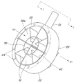
도 2와 도 3은 본 발명에 따른 차량용 요소수 혼합장치의 좌측 사시도 및 우측 사시도,
도 4는 도 2의 Ⅰ-Ⅰ선 단면도이다.1 is a schematic view of a vehicle urea water mixing device according to the present invention installed in an exhaust pipe,
2 and 3 are a left perspective view and a right perspective view of a vehicle urea water mixing device according to the present invention,
4 is a sectional view taken along line I-I in FIG. 2.
이하에서는 첨부된 도면을 참조하여 본 발명의 바람직한 일실시예에 따른 차량용 요소수 혼합장치에 대해 살펴보기로 한다.Hereinafter, with reference to the accompanying drawings will be described with respect to the vehicle urea water mixing device according to an embodiment of the present invention.
본 발명에 따른 차량용 요소수 혼합장치는 도 1 내지 도 4에 도시된 바와 같이 배기가스(1)와 요소수(2)를 혼합하는 혼합기구(10); 및 암모니아가스(3)를 분사하는 분사기구(20)를 포함하고; 상기 혼합기구(10)와 분사기구(20)는 한 개의 바디를 이루도록 일체로 구성되면서 배기관(4)내에 고정되게 설치된다.The urea water mixing device for a vehicle according to the present invention includes a
요소수탱크에 저장된 요소수(2)는 노즐(5)을 통해 배기관(4)내에 분사된다.The
배기관(4)내에 요소수(2)가 분사되면 분사된 요소수는 배기가스(1)와 혼합되면서 배기가스 열에 의해 열분해되어 암모니아로 변환된다.When the
본 발명에 따른 혼합기구(10)는 분사기구(20)에 일체로 결합되면서 방사상으로 배치된 다수개의 블레이드(11)를 포함한다.The
그리고, 블레이드(11)는 배기가스 흐름방향(M1)을 따라 소정각도로 굴곡진 원호모양으로 형성된다.Then, the
따라서, 배기가스(1)와 요소수(2)는 블레이드(11)를 통과한 후단에서 와류가 형성됨에 따라 배기가스(1)와 요소수(2)의 혼합길이(SCR촉매까지 도달하는데 소요되는 시간)을 증대시킬 수 있게 되고, 이를 통해 배기가스(1)와 요소수(2)의 혼합율을 높일 수 있게 된다.Accordingly, the
본 발명에 따른 분사기구(20)는 암모니아가스가 공급되는 파이프(21); 및 배기관(4)으로 암모니아가스(3)를 분사하는 하우징(22)을 포함한다.The
상기 파이프(21)는 암모니아고체가 저장된 탱크와 연결되고, 상기 하우징(22)은 파이프(21)와 연결된다.The
파이프(21)와 연결된 하우징(22)은 배기관(4)내에 고정되게 설치되고, 블레이드(11)가 일체로 결합되며, 내부에는 암모니아가스가 이동하는 가스통로(23)가 형성되고, 암모니아가스가 배출되는 다수개의 분사구멍(24)이 가스통로(23)와 연결되게 형성된다.The
분사구멍(24)은 적어도 1개 이상으로 형성되고, 각각의 지름은 3mm 이상으로 형성된 것이 바람직하지만, 이에 한정되는 것은 아니다.The
분사기구(20)를 구성하는 하우징(22)은 일면(22a)과 타면(22b)을 관통하는 중공홀(25)이 중심부에 형성된 원형링모양으로 형성되고, 상기 중공홀(25)내에 블레이드(11)가 위치하도록 구성된다.The
하우징(22)의 중공홀(25)내에 블레이드(11)가 위치하도록 구성됨에 따라 블레이드(11)의 설치공간을 별도로 확보할 필요가 없으며, 특히 혼합기구(10)와 분사기구(20)의 결합체 사이즈를 컴팩트하게 구성할 수 있게 된다.Since the
하우징(22)은 일면(22a)은 배기가스 흐름방향(M1)과 마주 대하는 면이고, 하우징(22)은 타면(22b)은 배기가스 흐름방향(M1)과 동일한 방향을 향하는 면으로 정의될 수 있다.
분사구멍(24)은 배기가스 흐름방향(M1)을 따라 하우징(22)의 일면(22a)과 타면(22b)중에서 어느 한쪽 면에만 형성될 수 있고, 또는 하우징(22)의 일면(22a)과 타면(22b)에 모두 형성될 수 있다.The
분사구멍(24)이 하우징(22)의 일면(22a)과 타면(22b)에 모두 형성되는 경우 암모니아가스의 분사량을 증대시킬 수 있게 됨에 따라 질소산화물의 정화율을 한층 더 높일 수 있게 된다.When the
본 발명에 따른 실시예는 다수개의 블레이드(11)를 일체로 연결해서 지지하는 중간링(30)을 더 포함할 수 있는 바, 중간링(30)을 이용해서 다수개의 블레이드(11)의 결합력을 견고하게 유지할 수 있게 된다.The embodiment according to the present invention may further include an
다수개의 블레이드(11)는 하우징(22)의 중공홀(25)로 삽입되어서 하우징(22)의 내주면과의 결합을 통해 블레이드(11)와 하우징(22)이 직접 결합될 수 있다.The plurality of
또는 외곽링(40)속에 다수개의 블레이드(11)를 삽입해서 다수개의 블레이드(11)와 외곽링(40)을 일체로 결합하고, 다수개의 블레이드(11)가 결합된 외곽링(40)을 하우징(22)의 중공홀(25)로 삽입해서 외곽링(40)의 외주면과 하우징(22)의 내주면을 일체로 결합하고, 이를 통해 다수개의 블레이드(11)가 외곽링(40)을 통해 하우징(22)과 일체화를 이루도록 결합된 구조도 가능할 것이다.Alternatively, by inserting a plurality of
이상 설명한 바와 같이 본 발명에 따른 차량용 요소수 혼합장치는, 배기가스(1)와 요소수(2)를 혼합하는 블레이드(11) 및 암모니아가스(3)를 분사하는 파이프(21)와 하우징(22)이 한 개의 바디가 되게 일체로 결합된 구성으로, 질소산화물의 정화를 위해 배기관(4)내에 설치되는 부품의 개수를 크게 줄일 수 있게 됨에 따라 배기관(4)내의 배압증가 현상을 예방할 수 있으며, 이를 통해 출력저하 현상을 예방할 수 있는 장점이 있다.As described above, the urea water mixing device for a vehicle according to the present invention includes a
또한, 암모니아가스(3)를 분사하기 위한 하우징(22)의 내부 중공홀(25)속에 다수개의 블레이드(11)가 위치하는 구성으로, 이를 통해 블레이드(11)의 설치공간을 별도로 확보할 필요가 없으며, 특히 혼합기구(10)와 분사기구(20)의 결합체 사이즈를 컴팩트하게 구성할 수 있는 장점도 있다.In addition, a configuration in which a plurality of
본 발명은 특정한 실시예에 관련하여 도시하고 설명하였지만, 이하의 특허청구범위에 의해 제공되는 본 발명의 기술적 사상을 벗어나지 않는 한도 내에서, 본 발명이 다양하게 개량 및 변화될 수 있다는 것은 당업계에서 통상의 지식을 가진 자에게 있어서 자명할 것이다.Although the present invention has been illustrated and described in connection with specific embodiments, it is understood in the art that the present invention may be variously improved and changed within the limits that do not depart from the technical spirit of the present invention provided by the following claims. It will be obvious to those of ordinary skill.
1 - 배기가스 2 - 요소수
3 - 암모니아가스 4 - 배기관
10 - 혼합기구 11 - 블레이드
20 - 분사기구 21 - 파이프
22 - 하우징 22a - 일면
22b - 타면 23 - 가스통로
24 - 분사구멍 25 - 중공홀
30 - 내부링 40 - 외곽링1-exhaust gas 2-urea water
3-Ammonia gas 4-Exhaust pipe
10-Mixing mechanism 11-Blade
20-Injection mechanism 21-Pipe
22-
22b-Other side 23-Gas passage
24-Injection hole 25-Hollow hole
30-Inner ring 40-Outer ring
Claims (7)
암모니아가스를 분사하는 분사기구를 포함하고;
상기 혼합기구와 분사기구는 한 개의 바디를 이루도록 일체로 구성되면서 배기관내에 고정되게 설치된 것을 특징으로 하는 차량용 요소수 혼합장치.A mixing mechanism for mixing exhaust gas and urea water; And
And an injection mechanism for injecting ammonia gas;
The mixing mechanism and the injection mechanism is integrally configured to form a body, the vehicle urea water mixing device, characterized in that fixedly installed in the exhaust pipe.
상기 혼합기구는 분사기구에 일체로 결합되면서 방사상으로 배치된 다수개의 블레이드를 포함하는 것을 특징으로 하는 차량용 요소수 혼합장치.The method according to claim 1,
The mixing mechanism is a vehicle urea water mixing device characterized in that it is integrally coupled to the injection mechanism and includes a plurality of blades arranged radially.
상기 블레이드는 배기가스 흐름방향을 따라 원호모양으로 형성되어서 블레이드를 통과한 후단에서 와류가 형성되도록 하는 것을 특징으로 하는 차량용 요소수 혼합장치.The method according to claim 2,
The blade is formed in an arc shape along the flow direction of the exhaust gas so that the urea water mixing device for a vehicle, characterized in that to form a vortex at the rear end passing through the blade.
상기 분사기구는 암모니아가스가 공급되는 파이프; 및
상기 파이프와 연결되면서 배기관내에 고정되게 설치되고, 블레이드가 일체로 결합되며, 내부에는 암모니아가스가 이동하는 가스통로가 형성되고, 암모니아가스가 배출되는 다수개의 분사구멍이 가스통로와 연결되게 형성된 하우징;을 포함하는 것을 특징으로 하는 차량용 요소수 혼합장치.The method according to claim 2,
The injection mechanism is a pipe through which ammonia gas is supplied; And
The housing is formed to be fixedly installed in the exhaust pipe while being connected to the pipe, the blades are integrally formed, a gas passage through which ammonia gas moves is formed, and a plurality of injection holes through which ammonia gas is discharged is connected to the gas passage. ; Urea water mixing device for a vehicle comprising a.
상기 하우징은 일면과 타면을 관통하는 중공홀이 중심부에 형성된 원형링모양으로 형성되고;
상기 중공홀내에 블레이드가 위치하도록 구성된 것을 특징으로 하는 차량용 요소수 혼합장치.The method according to claim 4,
The housing is formed in a circular ring shape in which a hollow hole penetrating one surface and the other surface is formed in the center;
A urea water mixing device for a vehicle, characterized in that the blade is configured to be positioned in the hollow hole.
상기 분사구멍은 배기가스 흐름방향을 따라 하우징의 일면과 타면중에서 어느 한쪽 면에만 형성되거나 또는 하우징의 일면과 타면에 모두 형성되도록 구성된 것을 특징으로 하는 차량용 요소수 혼합장치.The method according to claim 4,
The injection hole is a vehicle urea water mixing device characterized in that it is configured to be formed on either one side or the other side of the housing or one side of the other side of the housing along the flow direction of the exhaust gas.
상기 다수개의 블레이드를 일체로 연결해서 지지하는 중간링을 더 포함하는 것을 특징으로 하는 차량용 요소수 혼합장치.The method according to claim 2,
The urea water mixing device for a vehicle, further comprising an intermediate ring for supporting the plurality of blades integrally connected.
Priority Applications (1)
| Application Number | Priority Date | Filing Date | Title |
|---|---|---|---|
| KR1020180158451A KR20200070858A (en) | 2018-12-10 | 2018-12-10 | Urea blender for vehicle |
Applications Claiming Priority (1)
| Application Number | Priority Date | Filing Date | Title |
|---|---|---|---|
| KR1020180158451A KR20200070858A (en) | 2018-12-10 | 2018-12-10 | Urea blender for vehicle |
Publications (1)
| Publication Number | Publication Date |
|---|---|
| KR20200070858A true KR20200070858A (en) | 2020-06-18 |
Family
ID=71143329
Family Applications (1)
| Application Number | Title | Priority Date | Filing Date |
|---|---|---|---|
| KR1020180158451A KR20200070858A (en) | 2018-12-10 | 2018-12-10 | Urea blender for vehicle |
Country Status (1)
| Country | Link |
|---|---|
| KR (1) | KR20200070858A (en) |
Cited By (1)
| Publication number | Priority date | Publication date | Assignee | Title |
|---|---|---|---|---|
| KR20220107706A (en) | 2021-01-26 | 2022-08-02 | 융진기업 주식회사 | NOx Reduction Device |
Citations (1)
| Publication number | Priority date | Publication date | Assignee | Title |
|---|---|---|---|---|
| KR20170108191A (en) | 2016-03-16 | 2017-09-27 | 현대자동차주식회사 | Exhaust purification device for vehicle |
-
2018
- 2018-12-10 KR KR1020180158451A patent/KR20200070858A/en not_active Application Discontinuation
Patent Citations (1)
| Publication number | Priority date | Publication date | Assignee | Title |
|---|---|---|---|---|
| KR20170108191A (en) | 2016-03-16 | 2017-09-27 | 현대자동차주식회사 | Exhaust purification device for vehicle |
Cited By (1)
| Publication number | Priority date | Publication date | Assignee | Title |
|---|---|---|---|---|
| KR20220107706A (en) | 2021-01-26 | 2022-08-02 | 융진기업 주식회사 | NOx Reduction Device |
Similar Documents
| Publication | Publication Date | Title |
|---|---|---|
| CN100504047C (en) | Muffler device with exhaust gas purifying function | |
| US9057312B2 (en) | System and apparatus for reducing reductant deposit formation in exhaust aftertreatment systems | |
| WO2017215458A1 (en) | Exhaust gas postprocessing apparatus | |
| US20110271662A1 (en) | Compact reduction agent doser for use in an scr system of an internal combustion engine | |
| CN111691960A (en) | Exhaust system for internal combustion engine | |
| JP2011111927A (en) | Exhaust emission control device of internal combustion engine | |
| US11193412B2 (en) | Automotive exhaust aftertreatment system | |
| US10450921B2 (en) | Exhaust purification system | |
| JP2008144644A (en) | Exhaust emission control device for internal combustion engine | |
| US20230143888A1 (en) | Mixers for use in aftertreatment systems | |
| KR101981483B1 (en) | Exhaust gas cleaning device | |
| WO2020155834A1 (en) | Swirl vane-type urea injection mixing apparatus | |
| KR20200070858A (en) | Urea blender for vehicle | |
| JP5078733B2 (en) | Exhaust gas purification device for internal combustion engine | |
| WO2021225824A1 (en) | Configurable aftertreatment systems including a housing | |
| US20210301704A1 (en) | Serviceable catalyst and mixer unit for vehicle exhaust system | |
| KR100863433B1 (en) | Selective catalyst reduction device for exhaust system | |
| CN109958512B (en) | Exhaust treatment system for engine | |
| KR101898235B1 (en) | Mixing apparatus for selective catalytic reduction-catalysator | |
| CN111742123B (en) | Exhaust gas aftertreatment device for dosing a liquid exhaust gas aftertreatment agent | |
| JP2019143532A (en) | Reductant injection device | |
| CN209990529U (en) | Radial injection mixer device for mixing exhaust gas and reductant fluid | |
| JP5471089B2 (en) | Reducing agent supply device for urea SCR catalyst | |
| CN115335591B (en) | Exhaust denitration device | |
| US10794252B1 (en) | Direct spray exhaust mixer system |
Legal Events
| Date | Code | Title | Description |
|---|---|---|---|
| A201 | Request for examination | ||
| E902 | Notification of reason for refusal | ||
| E601 | Decision to refuse application |