KR20200070122A - Apparatus and method for managing battery - Google Patents
Apparatus and method for managing battery Download PDFInfo
- Publication number
- KR20200070122A KR20200070122A KR1020190161341A KR20190161341A KR20200070122A KR 20200070122 A KR20200070122 A KR 20200070122A KR 1020190161341 A KR1020190161341 A KR 1020190161341A KR 20190161341 A KR20190161341 A KR 20190161341A KR 20200070122 A KR20200070122 A KR 20200070122A
- Authority
- KR
- South Korea
- Prior art keywords
- signal
- frequency
- cell
- battery
- antenna
- Prior art date
Links
- 238000000034 method Methods 0.000 title claims description 25
- 230000007704 transition Effects 0.000 claims abstract description 22
- 238000005259 measurement Methods 0.000 claims description 39
- 238000004891 communication Methods 0.000 claims description 15
- 230000005856 abnormality Effects 0.000 claims description 14
- 230000002159 abnormal effect Effects 0.000 claims description 12
- 238000012544 monitoring process Methods 0.000 claims description 9
- 238000007599 discharging Methods 0.000 claims description 8
- 230000005540 biological transmission Effects 0.000 claims description 5
- 239000003990 capacitor Substances 0.000 description 14
- 230000015572 biosynthetic process Effects 0.000 description 8
- 238000010586 diagram Methods 0.000 description 8
- PXHVJJICTQNCMI-UHFFFAOYSA-N nickel Substances [Ni] PXHVJJICTQNCMI-UHFFFAOYSA-N 0.000 description 8
- HBBGRARXTFLTSG-UHFFFAOYSA-N Lithium ion Chemical compound [Li+] HBBGRARXTFLTSG-UHFFFAOYSA-N 0.000 description 6
- 229910001416 lithium ion Inorganic materials 0.000 description 6
- 229920002134 Carboxymethyl cellulose Polymers 0.000 description 5
- 238000009529 body temperature measurement Methods 0.000 description 5
- 235000010948 carboxy methyl cellulose Nutrition 0.000 description 5
- 229920006184 cellulose methylcellulose Polymers 0.000 description 5
- 239000011153 ceramic matrix composite Substances 0.000 description 5
- 238000012710 chemistry, manufacturing and control Methods 0.000 description 5
- 230000007274 generation of a signal involved in cell-cell signaling Effects 0.000 description 4
- UFHFLCQGNIYNRP-UHFFFAOYSA-N Hydrogen Chemical compound [H][H] UFHFLCQGNIYNRP-UHFFFAOYSA-N 0.000 description 2
- WHXSMMKQMYFTQS-UHFFFAOYSA-N Lithium Chemical compound [Li] WHXSMMKQMYFTQS-UHFFFAOYSA-N 0.000 description 2
- OJIJEKBXJYRIBZ-UHFFFAOYSA-N cadmium nickel Chemical compound [Ni].[Cd] OJIJEKBXJYRIBZ-UHFFFAOYSA-N 0.000 description 2
- 230000006870 function Effects 0.000 description 2
- 229910052739 hydrogen Inorganic materials 0.000 description 2
- 239000001257 hydrogen Substances 0.000 description 2
- 238000009434 installation Methods 0.000 description 2
- 229910052744 lithium Inorganic materials 0.000 description 2
- 229910052759 nickel Inorganic materials 0.000 description 2
- QELJHCBNGDEXLD-UHFFFAOYSA-N nickel zinc Chemical compound [Ni].[Zn] QELJHCBNGDEXLD-UHFFFAOYSA-N 0.000 description 2
- 229920000642 polymer Polymers 0.000 description 2
- 239000004065 semiconductor Substances 0.000 description 2
- 210000004556 brain Anatomy 0.000 description 1
- 238000001514 detection method Methods 0.000 description 1
- 238000004146 energy storage Methods 0.000 description 1
- 238000012986 modification Methods 0.000 description 1
- 230000004048 modification Effects 0.000 description 1
- 238000012827 research and development Methods 0.000 description 1
- 238000012546 transfer Methods 0.000 description 1
- 230000002618 waking effect Effects 0.000 description 1
Images


Classifications
-
- H—ELECTRICITY
- H02—GENERATION; CONVERSION OR DISTRIBUTION OF ELECTRIC POWER
- H02J—CIRCUIT ARRANGEMENTS OR SYSTEMS FOR SUPPLYING OR DISTRIBUTING ELECTRIC POWER; SYSTEMS FOR STORING ELECTRIC ENERGY
- H02J7/00—Circuit arrangements for charging or depolarising batteries or for supplying loads from batteries
- H02J7/0047—Circuit arrangements for charging or depolarising batteries or for supplying loads from batteries with monitoring or indicating devices or circuits
-
- H02J7/0022—
-
- G—PHYSICS
- G01—MEASURING; TESTING
- G01R—MEASURING ELECTRIC VARIABLES; MEASURING MAGNETIC VARIABLES
- G01R31/00—Arrangements for testing electric properties; Arrangements for locating electric faults; Arrangements for electrical testing characterised by what is being tested not provided for elsewhere
- G01R31/36—Arrangements for testing, measuring or monitoring the electrical condition of accumulators or electric batteries, e.g. capacity or state of charge [SoC]
- G01R31/382—Arrangements for monitoring battery or accumulator variables, e.g. SoC
-
- G—PHYSICS
- G01—MEASURING; TESTING
- G01R—MEASURING ELECTRIC VARIABLES; MEASURING MAGNETIC VARIABLES
- G01R31/00—Arrangements for testing electric properties; Arrangements for locating electric faults; Arrangements for electrical testing characterised by what is being tested not provided for elsewhere
- G01R31/36—Arrangements for testing, measuring or monitoring the electrical condition of accumulators or electric batteries, e.g. capacity or state of charge [SoC]
- G01R31/396—Acquisition or processing of data for testing or for monitoring individual cells or groups of cells within a battery
-
- H—ELECTRICITY
- H01—ELECTRIC ELEMENTS
- H01M—PROCESSES OR MEANS, e.g. BATTERIES, FOR THE DIRECT CONVERSION OF CHEMICAL ENERGY INTO ELECTRICAL ENERGY
- H01M10/00—Secondary cells; Manufacture thereof
- H01M10/42—Methods or arrangements for servicing or maintenance of secondary cells or secondary half-cells
- H01M10/425—Structural combination with electronic components, e.g. electronic circuits integrated to the outside of the casing
-
- H—ELECTRICITY
- H01—ELECTRIC ELEMENTS
- H01M—PROCESSES OR MEANS, e.g. BATTERIES, FOR THE DIRECT CONVERSION OF CHEMICAL ENERGY INTO ELECTRICAL ENERGY
- H01M10/00—Secondary cells; Manufacture thereof
- H01M10/42—Methods or arrangements for servicing or maintenance of secondary cells or secondary half-cells
- H01M10/44—Methods for charging or discharging
-
- H—ELECTRICITY
- H01—ELECTRIC ELEMENTS
- H01M—PROCESSES OR MEANS, e.g. BATTERIES, FOR THE DIRECT CONVERSION OF CHEMICAL ENERGY INTO ELECTRICAL ENERGY
- H01M10/00—Secondary cells; Manufacture thereof
- H01M10/42—Methods or arrangements for servicing or maintenance of secondary cells or secondary half-cells
- H01M10/48—Accumulators combined with arrangements for measuring, testing or indicating the condition of cells, e.g. the level or density of the electrolyte
- H01M10/482—Accumulators combined with arrangements for measuring, testing or indicating the condition of cells, e.g. the level or density of the electrolyte for several batteries or cells simultaneously or sequentially
-
- H—ELECTRICITY
- H02—GENERATION; CONVERSION OR DISTRIBUTION OF ELECTRIC POWER
- H02J—CIRCUIT ARRANGEMENTS OR SYSTEMS FOR SUPPLYING OR DISTRIBUTING ELECTRIC POWER; SYSTEMS FOR STORING ELECTRIC ENERGY
- H02J50/00—Circuit arrangements or systems for wireless supply or distribution of electric power
- H02J50/20—Circuit arrangements or systems for wireless supply or distribution of electric power using microwaves or radio frequency waves
-
- H—ELECTRICITY
- H02—GENERATION; CONVERSION OR DISTRIBUTION OF ELECTRIC POWER
- H02J—CIRCUIT ARRANGEMENTS OR SYSTEMS FOR SUPPLYING OR DISTRIBUTING ELECTRIC POWER; SYSTEMS FOR STORING ELECTRIC ENERGY
- H02J50/00—Circuit arrangements or systems for wireless supply or distribution of electric power
- H02J50/80—Circuit arrangements or systems for wireless supply or distribution of electric power involving the exchange of data, concerning supply or distribution of electric power, between transmitting devices and receiving devices
-
- H—ELECTRICITY
- H02—GENERATION; CONVERSION OR DISTRIBUTION OF ELECTRIC POWER
- H02J—CIRCUIT ARRANGEMENTS OR SYSTEMS FOR SUPPLYING OR DISTRIBUTING ELECTRIC POWER; SYSTEMS FOR STORING ELECTRIC ENERGY
- H02J7/00—Circuit arrangements for charging or depolarising batteries or for supplying loads from batteries
- H02J7/00032—Circuit arrangements for charging or depolarising batteries or for supplying loads from batteries characterised by data exchange
-
- H—ELECTRICITY
- H02—GENERATION; CONVERSION OR DISTRIBUTION OF ELECTRIC POWER
- H02J—CIRCUIT ARRANGEMENTS OR SYSTEMS FOR SUPPLYING OR DISTRIBUTING ELECTRIC POWER; SYSTEMS FOR STORING ELECTRIC ENERGY
- H02J7/00—Circuit arrangements for charging or depolarising batteries or for supplying loads from batteries
- H02J7/0013—Circuit arrangements for charging or depolarising batteries or for supplying loads from batteries acting upon several batteries simultaneously or sequentially
-
- H—ELECTRICITY
- H02—GENERATION; CONVERSION OR DISTRIBUTION OF ELECTRIC POWER
- H02J—CIRCUIT ARRANGEMENTS OR SYSTEMS FOR SUPPLYING OR DISTRIBUTING ELECTRIC POWER; SYSTEMS FOR STORING ELECTRIC ENERGY
- H02J7/00—Circuit arrangements for charging or depolarising batteries or for supplying loads from batteries
- H02J7/0029—Circuit arrangements for charging or depolarising batteries or for supplying loads from batteries with safety or protection devices or circuits
- H02J7/0031—Circuit arrangements for charging or depolarising batteries or for supplying loads from batteries with safety or protection devices or circuits using battery or load disconnect circuits
- H02J7/0032—Circuit arrangements for charging or depolarising batteries or for supplying loads from batteries with safety or protection devices or circuits using battery or load disconnect circuits disconnection of loads if battery is not under charge, e.g. in vehicle if engine is not running
-
- H—ELECTRICITY
- H02—GENERATION; CONVERSION OR DISTRIBUTION OF ELECTRIC POWER
- H02J—CIRCUIT ARRANGEMENTS OR SYSTEMS FOR SUPPLYING OR DISTRIBUTING ELECTRIC POWER; SYSTEMS FOR STORING ELECTRIC ENERGY
- H02J7/00—Circuit arrangements for charging or depolarising batteries or for supplying loads from batteries
- H02J7/0047—Circuit arrangements for charging or depolarising batteries or for supplying loads from batteries with monitoring or indicating devices or circuits
- H02J7/0048—Detection of remaining charge capacity or state of charge [SOC]
-
- H—ELECTRICITY
- H02—GENERATION; CONVERSION OR DISTRIBUTION OF ELECTRIC POWER
- H02J—CIRCUIT ARRANGEMENTS OR SYSTEMS FOR SUPPLYING OR DISTRIBUTING ELECTRIC POWER; SYSTEMS FOR STORING ELECTRIC ENERGY
- H02J9/00—Circuit arrangements for emergency or stand-by power supply, e.g. for emergency lighting
- H02J9/005—Circuit arrangements for emergency or stand-by power supply, e.g. for emergency lighting using a power saving mode
-
- H—ELECTRICITY
- H01—ELECTRIC ELEMENTS
- H01M—PROCESSES OR MEANS, e.g. BATTERIES, FOR THE DIRECT CONVERSION OF CHEMICAL ENERGY INTO ELECTRICAL ENERGY
- H01M10/00—Secondary cells; Manufacture thereof
- H01M10/42—Methods or arrangements for servicing or maintenance of secondary cells or secondary half-cells
- H01M10/425—Structural combination with electronic components, e.g. electronic circuits integrated to the outside of the casing
- H01M2010/4271—Battery management systems including electronic circuits, e.g. control of current or voltage to keep battery in healthy state, cell balancing
-
- H—ELECTRICITY
- H01—ELECTRIC ELEMENTS
- H01M—PROCESSES OR MEANS, e.g. BATTERIES, FOR THE DIRECT CONVERSION OF CHEMICAL ENERGY INTO ELECTRICAL ENERGY
- H01M10/00—Secondary cells; Manufacture thereof
- H01M10/42—Methods or arrangements for servicing or maintenance of secondary cells or secondary half-cells
- H01M10/425—Structural combination with electronic components, e.g. electronic circuits integrated to the outside of the casing
- H01M2010/4278—Systems for data transfer from batteries, e.g. transfer of battery parameters to a controller, data transferred between battery controller and main controller
-
- H—ELECTRICITY
- H02—GENERATION; CONVERSION OR DISTRIBUTION OF ELECTRIC POWER
- H02J—CIRCUIT ARRANGEMENTS OR SYSTEMS FOR SUPPLYING OR DISTRIBUTING ELECTRIC POWER; SYSTEMS FOR STORING ELECTRIC ENERGY
- H02J2207/00—Indexing scheme relating to details of circuit arrangements for charging or depolarising batteries or for supplying loads from batteries
- H02J2207/10—Control circuit supply, e.g. means for supplying power to the control circuit
Abstract
Description
본 발명은 배터리 셀 단위로 배터리의 상태를 모니터링하는 장치 및 방법에 관한 것이다.The present invention relates to an apparatus and method for monitoring the state of a battery in units of battery cells.
최근 이차 전지에 대한 연구 개발이 활발히 이루어지고 있다. 여기서 이차 전지는 충방전이 가능한 전지로서, 종래의 Ni/Cd 전지, Ni/MH 전지 등과 최근의 리튬 이온 전지를 모두 포함하는 의미이다. 이차 전지 중 리튬 이온 전지는 종래의 Ni/Cd 전지, Ni/MH 전지 등에 비하여 에너지 밀도가 훨씬 높다는 장점이 있다, 또한, 리튬 이온 전지는 소형, 경량으로 제작할 수 있어서, 이동 기기의 전원으로 사용된다. 또한, 리튬 이온 전지는 전기 자동차의 전원으로 사용 범위가 확장되어 차세대 에너지 저장 매체로 주목을 받고 있다.Recently, research and development for secondary batteries have been actively conducted. Here, the secondary battery is a battery that can be charged and discharged, and includes a conventional Ni/Cd battery, a Ni/MH battery, and all recent lithium ion batteries. Among secondary batteries, lithium ion batteries have an advantage of much higher energy density than conventional Ni/Cd batteries, Ni/MH batteries, and the like, and lithium ion batteries can be manufactured in a compact size and light weight, and are used as power sources for mobile devices. . In addition, the range of use of lithium-ion batteries as a power source for electric vehicles has been drawing attention as a next-generation energy storage medium.
이차 전지는 일반적으로 복수 개의 배터리 팩들로 구성되는 배터리 시스템에서 이용된다. 배터리 시스템을 구성하는 배터리 팩들은 복수의 배터리 모듈이 직렬 또는 병렬로 연결되어 구성되며, 각각의 배터리 모듈은 복수의 배터리 셀로 이루어질 수 있다. 이러한 배터리 시스템은 배터리 관리 시스템(BMS, battery management system)에 의하여 상태 및 동작이 관리 및 제어된다. BMS는 마스터에 해당하는 배터리 관리 제어기(BMC, Battery Management Controller)와 복수 개의 배터리 팩들을 각각 제어하는 복수 개의 셀 관리 제어기(CMC, Cell Management Controller)를 포함하여 구성된다. 그리고 배터리 팩에 포함된 각각의 배터리 모듈과 그에 포함된 배터리 셀들의 각각의 상태는 대응되는 CMC에 의하여 모니터링 되고 BMC에 의하여 취합됨으로써 BMS에 의해 배터리 시스템이 모니터링 된다.The secondary battery is generally used in a battery system composed of a plurality of battery packs. The battery packs constituting the battery system are configured by connecting a plurality of battery modules in series or in parallel, and each battery module may include a plurality of battery cells. In such a battery system, status and operation are managed and controlled by a battery management system (BMS). The BMS includes a battery management controller (BMC) corresponding to a master and a plurality of cell management controllers (CMC) that control a plurality of battery packs, respectively. In addition, the state of each battery module included in the battery pack and each of the battery cells included in the battery pack is monitored by the corresponding CMC and collected by the BMC, thereby monitoring the battery system by the BMS.
따라서, BMS가 배터리 셀들의 상태를 정확하게 파악하기 위하여는 BMC와 CMC를 효율적으로 동작시킬 필요가 있다.Therefore, in order for the BMS to accurately grasp the state of the battery cells, it is necessary to efficiently operate the BMC and the CMC.
본 발명의 목적은 기존의 배터리 관리 시스템에서, BMC와 CMC가 무선통신을 하는 경우 CMC가 주기적으로 깨어나는 일 없이 BMC와 효율적으로 통신할 수 있도록 하는 것이다.An object of the present invention is to allow the CMC to efficiently communicate with the BMC without periodically waking up when the BMC and the CMC perform wireless communication in the existing battery management system.
또한, 본 발명의 목적은 CMC가 감시하는 배터리 모듈의 폴트 상태를 전달할 수 있는 안전한 경로를 제공하는 것이다.In addition, it is an object of the present invention to provide a safe path to communicate the fault condition of the battery module monitored by the CMC.
본 발명의 일 실시예에 따른 셀 관리 제어기는 외부 장치와 제1 주파수를 이용하여 통신 가능한 제1 안테나; 외부 장치로부터의 제2 주파수의 신호를 수신 가능한 제2 안테나; 제2 안테나에서 수신된 제2 주파수의 신호에 기초하여 전압을 생성하는 전압 생성부; 전압 생성부에서 생성된 전압에 기초한 신호를 인에이블 신호로서 인가받는 구동부; 및 구동부로부터의 제어신호에 기초하여 배터리 셀의 상태를 나타내는 파라미터를 측정하는 셀 파라미터 측정부;를 포함하며, 인에이블 신호에 기초하여 상기 구동부가 대기 상태에서 웨이크업 상태로 천이한다.A cell management controller according to an embodiment of the present invention includes a first antenna capable of communicating with an external device using a first frequency; A second antenna capable of receiving a signal of a second frequency from an external device; A voltage generator that generates a voltage based on the signal of the second frequency received from the second antenna; A driver that receives a signal based on the voltage generated by the voltage generator as an enable signal; And a cell parameter measuring unit measuring a parameter indicating a state of the battery cell based on a control signal from the driving unit, and the driving unit transitions from a standby state to a wake-up state based on an enable signal.
본 실시예에 있어서, 제1 주파수와 제2 주파수는 상이한 주파수일 수도 있고, 동일한 주파수일 수도 있다.In this embodiment, the first frequency and the second frequency may be different frequencies, or may be the same frequency.
본 실시예에 있어서, 제2 주파수의 신호는 제1 주파수의 신호보다 에너지 밀도가 더 높을 수 있다.In this embodiment, the signal of the second frequency may have a higher energy density than the signal of the first frequency.
본 실시예에 있어서, 제2 주파수의 신호는 CW 신호일 수 있다.In this embodiment, the signal of the second frequency may be a CW signal.
본 실시예에 있어서, 셀 관리 제어기는 제2 안테나에서 제2 주파수의 신호를 수신 가능하도록 임피던스를 매칭시키는 임피던스 매칭 회로를 더 포함할 수 있다.In the present embodiment, the cell management controller may further include an impedance matching circuit that matches the impedance to receive a signal of the second frequency from the second antenna.
본 실시예에 있어서, 셀 관리 제어기는 전압 생성부에 축적되는 에너지를 방전시키기 위한 방전회로를 더 포함할 수 있다.In this embodiment, the cell management controller may further include a discharge circuit for discharging energy accumulated in the voltage generator.
본 실시예에 있어서, 구동부는 셀 파라미터 측정부로부터 수신한 배터리 셀의 파라미터 값에 기초하여 배터리 셀의 이상 여부를 판단하고, 배터리 셀에 이상이 발생하였다고 판단된 경우, 외부 장치에 배터리 셀의 이상 상태를 나타내는 폴트 신호를 제3 주파수로 전송할 수 있다.In the present embodiment, the driving unit determines whether the battery cell is abnormal based on the parameter value of the battery cell received from the cell parameter measurement unit, and when it is determined that an abnormality has occurred in the battery cell, the battery cell is abnormal in the external device. A fault signal indicating the state may be transmitted at a third frequency.
본 실시예에 있어서, 제1 주파수와 제3 주파수는 상이한 주파수일 수도 있고, 동일한 주파수일 수도 있다.In this embodiment, the first frequency and the third frequency may be different frequencies or may be the same frequency.
본 실시예에 있어서, 제3 주파수의 신호는 제1 주파수의 신호보다 에너지 밀도가 더 높을 수 있다.In this embodiment, the signal of the third frequency may have a higher energy density than the signal of the first frequency.
본 실시예에 있어서, 제3 주파수의 신호는 CW 신호일 수 있다.In this embodiment, the signal of the third frequency may be a CW signal.
본 실시예에 있어서, 폴트 신호는 제1 안테나를 통하여 전송될 수 있다.In this embodiment, the fault signal can be transmitted through the first antenna.
본 실시예에 있어서, 셀 관리 제어기는 구동부로 전력을 공급하는 전원 회로를 더 포함하고, 전원 회로는 전압 생성부에서 생성된 전압이 입력될 때 구동부에 인에이블 신호를 인가하고, 구동부는 전원 회로로부터 인가되는 인에이블 신호에 기초하여 웨이크업 상태로 천이할 수 있다.In this embodiment, the cell management controller further includes a power supply circuit that supplies power to the driving unit, and the power supply circuit applies an enable signal to the driving unit when a voltage generated by the voltage generation unit is input, and the driving unit is a power supply circuit. It may transition to the wake-up state based on the enable signal applied from.
본 실시예에 있어서, 셀 관리 제어기는 구동부로 전력을 공급하는 전원 회로를 더 포함하고, 전원 회로는 구동부에 전력을 상시 공급하며, 구동부는 전압 생성부에서 생성된 전압을 인에이블 신호로서 인가받을 수 있다.In this embodiment, the cell management controller further includes a power supply circuit that supplies power to the driving unit, the power supply circuit supplies power to the driving unit at all times, and the driving unit receives voltage generated by the voltage generation unit as an enable signal. Can be.
본 발명의 다른 실시예에 따른 배터리 관리 제어기는 외부 장치와 제1 주파수 및 제2 주파수를 이용하여 통신 가능한 제1 안테나; 및 외부 장치를 대기 상태에서 웨이크업 상태로 천이시키기 위한 웨이크업 신호를 제2 주파수의 신호로서 생성하여 제1 안테나를 통하여 외부 장치로 전송하고, 외부 장치와의 데이터 송수신을 제1 주파수로 수행하는 제어부;를 포함하며, 제어부는 제2 주파수의 신호의 에너지 밀도가 제1 주파수의 신호의 에너지 밀도보다 크도록 제1 주파수의 신호 및 제2 주파수의 신호를 생성한다.A battery management controller according to another embodiment of the present invention includes a first antenna capable of communicating with an external device using a first frequency and a second frequency; And generating a wake-up signal for transitioning the external device from the standby state to the wake-up state as a signal of the second frequency, transmitting the signal to the external device through the first antenna, and performing data transmission and reception with the external device at the first frequency. The control unit; includes, the control unit generates a signal of the first frequency and the signal of the second frequency so that the energy density of the signal of the second frequency is greater than the energy density of the signal of the first frequency.
본 실시예에 있어서, 배터리 관리 제어기는 외부 장치로부터 제3 주파수의 신호를 수신 가능한 제2 안테나를 더 포함하고, 제어부는 제2 안테나로부터 제3 주파수의 신호를 수신하였을 때, 외부 장치가 모니터링하는 배터리 셀에 이상이 발생하였다고 판단할 수 있다.In this embodiment, the battery management controller further includes a second antenna capable of receiving a signal of a third frequency from an external device, and the control unit monitors when the signal of the third frequency is received from a second antenna. It can be determined that an abnormality has occurred in the battery cell.
본 실시예에 있어서, 제어부는 제2 안테나로부터 미리 설정된 기준 이상의 에너지를 갖는 제3 주파수의 신호를 수신하는 것을 검출하는 경우, 외부 장치가 모니터링하는 배터리 셀에 이상이 발생하였다고 판단할 수 있다.In the present exemplary embodiment, when detecting that a signal having a third frequency having a predetermined energy or higher is received from the second antenna, the control unit may determine that an abnormality has occurred in the battery cell monitored by the external device.
본 실시예에 있어서, 배터리 관리 제어기는 제2 안테나에서 제3 주파수의 신호를 수신 가능하도록 임피던스를 매칭시키는 임피던스 매칭 회로; 및 임피던스 매칭 회로를 통하여 수신되는 신호에 의하여 축적되는 에너지를 방전시키기 위한 방전회로를 더 포함할 수 있다.In the present embodiment, the battery management controller includes: an impedance matching circuit that matches impedances so that signals of a third frequency can be received from the second antenna; And it may further include a discharge circuit for discharging the energy accumulated by the signal received through the impedance matching circuit.
본 발명의 다른 실시예에 따른 배터리 관리 시스템은, 배터리 셀의 상태를 모니터링 하는 복수의 셀 관리 제어기; 및 셀 관리 제어기와 통신하여 셀 관리 제어기로부터 배터리 셀에 대하여 측정한 파라미터값을 수신하는 배터리 관리 제어기;를 포함하며, 복수의 셀 관리 제어기 각각은, 배터리 관리 제어기와 제1 주파수를 이용하여 통신 가능하도록 구성된 제1 안테나와, 배터리 관리 제어기로부터 제2 주파수의 신호를 수신 가능하도록 구성된 제2 안테나와, 제2 안테나에서 수신하는 제2 주파수의 신호에 기초하여 전압을 생성하도록 구성된 전압 생성부와, 전압 생성부에서 생성된 전압에 기초한 신호를 인에이블 신호로서 인가받도록 구성된 구동부와, 구동부로부터의 제어신호에 기초하여 배터리 셀의 상태를 나타내는 파라미터를 측정하도록 구성된 셀 파라미터 측정부를 포함하며, 인에이블 신호에 기초하여 구동부가 대기 상태에서 웨이크업 상태로 천이한다.Battery management system according to another embodiment of the present invention, a plurality of cell management controller for monitoring the state of the battery cell; And a battery management controller that communicates with the cell management controller to receive parameter values measured for the battery cells from the cell management controller, and each of the plurality of cell management controllers can communicate with the battery management controller using a first frequency. A first antenna configured to receive, a second antenna configured to receive a signal of a second frequency from the battery management controller, and a voltage generator configured to generate a voltage based on the signal of the second frequency received from the second antenna, And a driving unit configured to receive a signal based on the voltage generated by the voltage generating unit as an enable signal, and a cell parameter measuring unit configured to measure a parameter indicating a state of the battery cell based on a control signal from the driving unit, and an enable signal Based on this, the driving unit transitions from the standby state to the wake-up state.
본 실시예에 있어서, 복수의 셀 관리 제어기 각각에서 구동부는 셀 파라미터 측정부로부터 수신한 배터리 셀의 파라미터 값에 기초하여 배터리 셀의 이상 여부를 판단하고, 배터리 셀에 이상이 발생하였다고 판단된 경우, 배터리 관리 제어기에 배터리 셀의 이상 상태를 나타내는 폴트 신호를 미리 설정된 제3 주파수로 전송하며, 복수의 셀 관리 제어기들은 미리 설정된 제3 주파수가 서로 상이한 주파수일 수 있다.In this embodiment, in each of the plurality of cell management controllers, the driving unit determines whether the battery cell is abnormal based on the parameter value of the battery cell received from the cell parameter measurement unit, and when it is determined that an abnormality has occurred in the battery cell, The fault signal indicating the abnormal state of the battery cell is transmitted to the battery management controller at a preset third frequency, and the plurality of cell management controllers may have different preset frequencies.
본 실시예에 있어서, 배터리 관리 제어기는 복수의 셀 관리 제어기로부터의 폴트 신호를 수신하기 위하여 복수의 셀 관리 제어기들이 폴트 신호를 송신하는 서로 상이한 제3 주파수들을 포함하는 주파수 범위를 스캐닝할 수 있다.In this embodiment, the battery management controller may scan a frequency range including different third frequencies where a plurality of cell management controllers transmit a fault signal to receive a fault signal from the plurality of cell management controllers.
본 발명의 일 측면에 따르면, CMC의 대기 전력을 “0”에 근접하게 구현 가능하여, 배터리 전류 소모를 줄여 배터리 방전을 방지할 수 있다.According to an aspect of the present invention, the standby power of the CMC can be implemented close to “0”, thereby reducing battery current consumption to prevent battery discharge.
본 발명의 일 측면에 따르면, RF 모듈을 추가하지 않고도, 폴트 신호를 BMC로 전달할 수 있다. 또한, 본 발명의 일 측면에 따르면, 폴트 신호를 즉시 전달할 수 있다.According to one aspect of the present invention, a fault signal can be transmitted to the BMC without adding an RF module. In addition, according to an aspect of the present invention, a fault signal can be transmitted immediately.
도 1은 본 발명의 일 실시예에 따른 셀 관리 제어기의 간략한 구성도이다.
도 2는 본 발명의 일 실시예에 따른 배터리 상태 모니터링 방법의 간략한 순서도이다.
도 3에는 본 발명의 일 실시예에 따른 셀 관리 제어기와 배터리 관리 제어기의 구성도가 간략히 도시되어 있다.
도 4는 본 발명의 일 실시예 또는 다른 실시예의 다단 정류 회로의 구현예를 도시한다.
도 5는 본 발명의 다른 실시예에 따른 셀 관리 제어기의 간략한 구성도이다.
도 6는 본 발명의 다른 실시예에 따른 배터리 상태 모니터링 방법의 간략한 순서도이다.
도 7은 본 발명의 다른 실시예에 따른 셀 관리 제어기와 배터리 관리 제어기의 구성도가 간략히 도시되어 있다.1 is a simplified configuration diagram of a cell management controller according to an embodiment of the present invention.
2 is a simplified flowchart of a method for monitoring a battery condition according to an embodiment of the present invention.
3 is a schematic diagram of a cell management controller and a battery management controller according to an embodiment of the present invention.
4 shows an implementation of a multi-stage rectifying circuit in one or another embodiment of the present invention.
5 is a simplified configuration diagram of a cell management controller according to another embodiment of the present invention.
6 is a simplified flowchart of a battery condition monitoring method according to another embodiment of the present invention.
7 is a schematic diagram of a cell management controller and a battery management controller according to another embodiment of the present invention.
이하, 본 발명의 일부 실시예들을 예시적인 도면을 통해 상세하게 설명한다. 각 도면의 구성요소들에 참조부호를 부가함에 있어서, 동일한 구성요소들에 대해서는 비록 다른 도면상에 표시되더라도 가능한 한 동일한 부호를 가지도록 하고 있음에 유의해야 한다. 또한, 본 발명의 실시예를 설명함에 있어서, 관련된 공지 구성 또는 기능에 대한 구체적인 설명이 본 발명의 실시예에 대한 이해를 방해한다고 판단되는 경우에는 그 상세한 설명은 생략하기로 한다.Hereinafter, some embodiments of the present invention will be described in detail through exemplary drawings. It should be noted that in adding reference numerals to the components of each drawing, the same components have the same reference numerals as possible even though they are displayed on different drawings. In addition, in describing embodiments of the present invention, when it is determined that detailed descriptions of related well-known configurations or functions interfere with understanding of the embodiments of the present invention, detailed descriptions thereof will be omitted.
종래에는 BMS에서 배터리의 상태 및 성능을 관리하기 위하여, 마스터에 해당하는 BMC(배터리 관리 제어기, battey management controller)가 상위 제어부로부터 동작 시작 명령을 수신하면 BMC는 슬레이브에 해당하는 하위의 CMC(셀 관리 제어기, cell management controller)를 깨워서 해당 CMC가 연결되는 배터리 셀의 전압 또는 온도 등의 배터리 상태를 나타내는 파라미터들의 모니터링을 시작하였다. 여기서, BMC와 CMC는 BMS에 포함되는 모듈이다. Conventionally, in order to manage the state and performance of the battery in the BMS, when the BMC (battery management controller) corresponding to the master receives an operation start command from the upper control unit, the BMC manages the lower CMC (cell management) corresponding to the slave. The controller, cell management controller, was awakened to start monitoring parameters indicating battery status, such as the voltage or temperature of the battery cell to which the CMC is connected. Here, BMC and CMC are modules included in BMS.
종래의 BMC와 CMC 간의 무선통신이 적용되는 경우, 유선이 아니기 때문에, CMC는 BMC로부터 수신되는 웨이크 업(wake up) 신호를 받기 위해 계속 혹은 주기적으로 깨어나 지속적으로 전류를 소모한다. 이러한 CMC의 지속적인 전류 소모로 인하여, 불필요한 전류가 소모되어, 향후 배터리의 방전을 유발할 수 있다. When the conventional wireless communication between the BMC and the CMC is applied, since it is not wired, the CMC continuously wakes up or periodically wakes up to receive a wake up signal received from the BMC and continuously consumes current. Due to the continuous current consumption of the CMC, unnecessary current is consumed, which may cause discharge of the battery in the future.
따라서, BMC로부터 배터리 상태를 확인하기 위한 신호를 수신하기 위하여, CMC가 주기적으로 깨어나는 방법 이외의 좀 더 효율적이고, 전류를 절약할 수 있는 방법이 필요하다. Therefore, in order to receive a signal for checking the battery status from the BMC, there is a need for a more efficient and current-saving method other than the method in which the CMC is periodically woken up.
또한, 안전을 위하여 CMC가 배터리 셀의 상태(배터리 셀의 전압 및 온도를 측정하여 배터리 셀의 상태 체크)를 체크한 뒤, 배터리 셀(또는 모듈)의 상태에 문제가 있다고 판단되면, 폴트(fault) 신호를 BMC로 전달할 수 있는 다양한 경로가 필요하다. 이러한 문제를 해결하기 위한 본 발명의 구성 및 동작 방법을 이하에서 설명하도록 한다. In addition, for safety reasons, after the CMC checks the state of the battery cell (measures the battery cell's voltage and temperature to check the state of the battery cell), if it is determined that there is a problem with the state of the battery cell (or module), a fault ) A variety of routes are needed to transmit signals to the BMC. The configuration and operation method of the present invention for solving this problem will be described below.
우선, 도 1을 참조하여 본 발명의 일 실시예에 따른 셀 관리 제어기(100)에 대해 살펴보도록 한다.First, with reference to Figure 1 to look at the
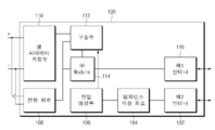
도 1은 본 발명의 일 실시예에 따른 셀 관리 제어기(100)의 간략한 구성도이다.1 is a simplified configuration diagram of a
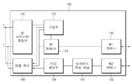
셀 관리 제어기(100)는 제2 안테나(102), 임피던스 매칭 회로(104), 전압 생성부(106), 전원 회로(108), 셀 파라미터 측정부(110), 구동부(112), RF 모듈(114) 및 제1 안테나(116)를 포함할 수 있다.The
여기서, 배터리의 종류는 특별히 한정되지 않으며, 예를 들어 배터리는 리튬 이온 전지, 리튬 폴리머 전지, 니켈 카드뮴 전지, 니켈 수소 전지, 니켈 아연 전지 등으로 구성될 수 있다. Here, the type of the battery is not particularly limited, and for example, the battery may be composed of a lithium ion battery, a lithium polymer battery, a nickel cadmium battery, a nickel hydrogen battery, a nickel zinc battery, or the like.
또한, 배터리는 복수의 배터리 셀이 직렬 및/또는 병렬로 연결되어 있는 배터리 모듈로 형성되고, 복수의 배터리 모듈이 직렬 및/또는 병렬로 연결되어 배터리 팩이 형성된다. 배터리는 하나 이상의 배터리 팩을 포함할 수 있다.Further, the battery is formed of a battery module in which a plurality of battery cells are connected in series and/or in parallel, and a battery pack is formed by connecting a plurality of battery modules in series and/or in parallel. The battery can include one or more battery packs.
제2 안테나(102)는 외부 장치, 예를 들어 BMC로부터 제2 주파수를 가지는 RF 신호를 수신한다. 제2 안테나(102)와는 달리 제1 안테나(116)는 외부 장치로부터 제1 주파수를 가지는 RF 신호를 수신하여 일반적인 통신을 수행할 수 있다. 제2 안테나(102)에서 수신되는 RF 신호는 임피던스 매칭 회로(104)를 통해서 임피던스 매칭된다. 즉, 임피던스 매칭 회로(104)는 수신되는 RF 신호 중 미리 매칭되어 있는 주파수인 제2 주파수를 가지는 RF 신호를 선별하여 전압 생성부(106)로 전달한다. The
제2 안테나(102)에서 외부 장치로부터 수신된 RF 신호는 전압 생성부(106)로 전달된다. The RF signal received from the external device at the
제2 안테나(102)로부터 RF 신호를 수신한 전압 생성부(106)는 수신된 RF 신호를 이용하여 전압을 생성한다. 즉, 전압 생성부(106)는 제2 안테나(102)에서 수신된 제2 주파수를 가지는 RF 신호에 기초하여 전압을 생성한다. 제2 안테나(102)에서 수신하는 제2 주파수를 가지는 RF 신호는 제1 안테나(116)에서 BMC와 통신하기 위하여 주고받는 제1 주파수를 가지는 RF 신호에 비하여 에너지 밀도가 높다. 이는 제2 주파수를 가지는 RF 신호에 기초하여 후술하는 인에이블 신호로서 사용할 수 있는 전압이 생성되어야 하기 때문이다. 이러한 제2 주파수를 가지는 RF 신호는 데이터를 포함하지 않는 신호일 수 있다. 즉, 제2 주파수를 가지는 RF 신호는 변조되지 않은 신호일 수 있다. 예를 들어, 제2 주파수를 가지는 RF 신호는 CW(Continuous Wave) 신호일 수 있다. 즉, 제2 주파수를 가지는 RF 신호는 단순히 소정의 에너지 밀도 이상의 에너지를 셀 관리 제어기(100)에 전달하기 위한 신호일 수 있다.The
전압 생성부(106)는 예를 들어, 다단 정류 회로일 수 있다. 다만, 수신된 RF 신호로 구동부(112)를 웨이크업 상태로 천이시킬 정도의 전압을 생성하는 것이 어렵게 때문에, 높은 전압 형성을 위해 필요 전압까지 다단으로 구현할 수 있다. 즉, 다단 정류 회로는 제2 주파수를 가지는 RF 신호로부터 생성되어야 할 전압에 따라 단수가 조절될 수 있다. The
전압 생성부(106)는 다단 정류 회로를 구성하기 위하여 복수 개의 다이오드와 복수 개의 캐패시터를 포함할 수 있다. 다이오드는 예를 들어, 빠른 정류 및 높은 전압 형성을 위하여 다이오드의 문턱 전압(Vf)이 작고, 상태 천이 속도가 빠른 RF 다이오드일 수 있다. The
전압 생성부(106)에서 RF 신호를 수신하여 전압을 생성하면, 구동부(112)에서 이를 감지하여 인에이블된다. 즉, 구동부(112)는 전압 생성부에서 생성된 전압에 기초한 신호를 인에이블 신호로서 인가받는다. 이 때, 구동부(112)는 전원 회로(108)로부터 상기 전력을 공급받는다. 구동부(112)는 예를 들어, 셀 관리 제어기(100) 내의 구성 각각을 제어하는 MCU(Micro Controller Unit)일 수 있다. MCU는 대부분의 전자제품에 채용돼 전자제품의 두뇌역할을 하는 핵심칩으로 단순 시간예약에서부터 특수한 기능에 이르기까지 제품의 다양한 특성을 컨트롤하는 역할을 하는 비메모리 반도체(시스템 반도체)이다. When the
전원 회로(108)로부터 인에이블 신호를 받아 인에이블된 구동부(112)가 RF 모듈(114)을 인에이블시킨다. The enable
셀 파라미터 측정부(110)는 배터리에 연결되고, 구동부(112)에서 수신한 제어 신호에 기초하여 배터리 셀의 상태를 나타내는 파라미터를 측정한다. 배터리 셀의 상태를 나타내는 파라미터는 전압 또는 온도 중 적어도 하나일 수 있다. 셀 파라미터 측정부(110)는 본 도면에서 하나로 도시되어 있으나, 셀 전압 측정부 및 셀 온도 측정부로 별개의 구성으로도 구성될 수도 있다. 셀 파라미터 측정부(110)에서 측정한 셀의 전압 및 온도에 대한 데이터를 구동부(112)로 전송한다. The cell
셀 파라미터 측정부(110)로부터 수신한 배터리 셀의 파라미터 값에 기초하여, 구동부(112)는 배터리 셀의 이상 여부를 판단한다. 즉, 셀 파라미터 측정부(110)로부터 셀의 전압 및 온도에 대한 데이터를 수신한 구동부(112)는, 해당 셀의 측정 전압 및 온도가 셀의 정상 동작의 범위 내인지 여부를 판단한다. 예를 들어, 측정된 셀의 전압이 제1 임계치보다 크거나 제2 임계치보다 작으면, 구동부(112)는 셀의 상태에 문제가 있다고 판단한다. 구동부(112)에서 셀의 상태가 문제가 있다고 판단되면, RF 모듈(114)로 하여금 미리 설정된 주파수의 폴트 신호를 생성하도록 한다. 또한, 예를 들어, 측정된 셀의 온도가 제3 임계치보다 크면, 구동부(112)는 셀의 상태에 문제가 있다고 판단한다. 구동부(112)에서 셀의 상태에 문제가 있다고 판단되면, RF 모듈(114)로 하여금 폴트 신호를 생성하도록 한다. 즉, 배터리 셀에 이상이 발생하였다고 판단된 경우, 외부 장치로 배터리 셀의 이상 상태를 나타내는 폴트 신호를 상기 제1 주파수와는 상이한 제3 주파수로 전송한다. Based on the parameter value of the battery cell received from the cell
이때, 제3 주파수로 전송하는 신호 또한 제2 주파수의 신호와 마찬가지로, BMC와 통신하기 위하여 주고받는 제1 주파수를 가지는 RF 신호에 비하여 에너지 밀도가 높다. 이는 제3 주파수를 가지는 RF 신호에 기초하여 배터리 관리 제어기(BMC)에서 전압이 생성되어야 하기 때문이다. 그리고 제3 주파수를 가지는 RF 신호인 폴트 신호는 데이터를 포함하지 않는 신호일 수 있다. 즉, 제3 주파수를 가지는 RF 신호는 변조되지 않은 신호일 수 있다. 예를 들어, 제3 주파수를 가지는 RF 신호는 CW(Continuous Wave) 신호일 수 있다. 즉, 폴트 신호는 단순히 소정의 에너지 밀도 이상의 에너지를 BMC에 전달하기 위한 신호일 수 있다.At this time, the signal transmitted at the third frequency, as well as the signal at the second frequency, has a higher energy density than the RF signal having the first frequency exchanged to communicate with the BMC. This is because a voltage must be generated in the battery management controller (BMC) based on the RF signal having the third frequency. The fault signal, which is an RF signal having a third frequency, may be a signal that does not contain data. That is, the RF signal having the third frequency may be an unmodulated signal. For example, the RF signal having a third frequency may be a CW (Continuous Wave) signal. That is, the fault signal may simply be a signal for transmitting energy above a predetermined energy density to the BMC.
본 실시예에서는 구동부(112)와 셀 파라미터 측정부(110)가 별도의 구성으로 이루어진 것으로 기재하였으나, 이는 예시적인 것으로 이들이 하나의 통합된 구성으로 구현될 수도 있을 것이다. In this embodiment, the driving
RF 모듈(114)은 구동부(112)가 전압 생성부(106)에서 생성된 전압에 기초한 인에이블 신호를 수신하면 구동부(112)가 인에이블시킨다. 또한, 구동부(112)가 셀의 상태에 문제가 있다고 판단하여, 구동부(112)로부터 폴트 신호 생성 신호를 수신하면, RF 모듈(114)은 제3 주파수를 가지는 폴트 신호를 생성하여 제1 안테나(116)로 전송한다. The
제1 안테나(116)는 RF 모듈(114)로부터 폴트 신호를 수신한다. RF 모듈(114)로부터 폴트 신호를 수신한 제1 안테나(116)는 외부 장치, 예를 들어 BMC로 폴트 신호를 전송한다. 즉, 폴트 신호는 제1 안테나를 통하여 전송된다. 제1 안테나(116)는 또한 BMC로 폴트 신호를 전송하는 것 이외에도, BMC와 일반적인 통신을 하는 안테나이다. The
한편, 도시하지는 않았으나, 전압 생성부(106)인 다단 정류 회로에 축적된 에너지를 방전시키기 위한 방전회로를 더 포함할 수 있다. 다단 정류 회로에는 제2 주파수의 신호 이외의 신호나 노이즈에 의하여 소정의 에너지가 축적될 수 있다. 축적된 에너지가 어느 정도 이상이 되면 제2 주파수의 RF 신호를 수신하지 않아도 전압 생성부(106)가 전압을 생성하여 구동부(112)가 인에이블 되는 문제가 발생할 수 있다. 따라서 다단 정류 회로에 축적된 에너지를 주기적으로 혹은 소정의 조건을 만족시킬 때(예를 들어, 축적된 에너지가 기준치 이상일 때) 방전시킬 필요가 있다.On the other hand, although not shown, it may further include a discharge circuit for discharging the energy accumulated in the multi-stage rectification circuit, the
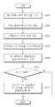
도 2는 본 발명의 일 실시예에 따른 배터리 상태 모니터링 방법의 간략한 순서도이다. 2 is a simplified flowchart of a method for monitoring a battery condition according to an embodiment of the present invention.
셀 관리 제어기(100)는 BMC로부터 RF 신호를 수신하기 전까지는, MCU가 래치(latch)하는 데에 필요한 전력만 소비하므로, “0”에 가까운 대기 전력만을 소모하면서 대기를 할 수 있다. 즉, 셀 관리 제어기(100)는 RF 신호를 수신한 후에 동작을 하기 때문에, RF 신호를 수신하기 전에 주기적으로 깨어날 필요가 없다. The
셀 관리 제어기(100)는 대기 상태에 있는 상태로, 제2 안테나(102)가 외부 장치, 예를 들어 BMC로부터 제2 주파수를 가지는 RF 신호를 수신한다(S200). 이 때, 임피던스 매칭 회로(104)가 제2 안테나(102)에서 수신되는 RF 신호 중 미리 매칭되어 있는 주파수의 RF 신호를 선별하여 전압 생성부(106)로 전달한다. The
제2 안테나(102)에서 BMC로부터 수신된 RF 신호는 전압 생성부(106)로 전달된다. 제2 안테나(102)로부터 RF 신호를 수신한 전압 생성부(106)는 구동부(112)로 인에이블 신호를 전송하기 위한 전압을 생성한다(S202). The RF signal received from the BMC at the
전압 생성부(106)는 예를 들어, 정류 회로일 수 있다. 다만, 전압 생성부(106)를 구성하는 정류 회로는 수신된 RF 신호로 구동부(112)로 인에이블 신호를 생성하여 전송할 정도의 전압을 생성하는 것이 어렵기 때문에, 높은 전압 형성을 위해 필요 전압까지 다단으로 구현할 수 있다. The
전압 생성부(106)는 다단 정류 회로를 구성하기 위하여 복수 개의 다이오드와 복수 개의 캐패시터를 포함할 수 있다. 다이오드는 예를 들어, 빠른 정류 및 높은 전압 형성을 위하여 다이오드의 문턱 전압(Vf)이 작고, 상태 천이 속도가 빠른 RF 다이오드일 수 있다.The
전압 생성부(106)에서 RF 신호를 수신하여 전압을 생성하면, 이를 구동부(112)에서 감지한다(S204). 즉, 구동부(112)는 전압 생성부(106)에서 생성된 전압에 기초한 인에이블 신호를 인가받는다. 전압 생성부(106)에서 생성된 전압을 감지한 구동부(112)는 인에이블되어 셀 관리 제어기(100) 내의 각 회로들을 인에이블시킨다(S206). 구동부(112)는 예를 들어, 셀 관리 제어기(100) 내의 구성을 각각 제어하는 MCU일 수 있다. When the
즉, 구동부(112)가 RF 모듈(114)을 인에이블시킨다. 구동부(112)로부터 인에이블 신호를 받은 전원 회로(108)는 배터리로부터 전류를 공급받아 RF 모듈(114)에 전력을 공급한다. 이 실시예에서는 구동부(112)는 전원 회로(108)로부터 최소한의 상시 전력을 공급받는다. 셀 파라미터 측정부(110)는 배터리로부터 직접 전력을 공급받을 수도 있고, 전원 회로(108)로부터 공급받을 수도 있다. That is, the driving
구동부(112)로부터 셀 파라미터 측정 신호(제어 신호)를 수신한 셀 파라미터 측정부는 셀의 전압 및 온도를 측정한다(S208). 셀 파라미터 측정부(110)는 배터리 셀과 연결되어 배터리 셀의 전압 및 온도를 측정한다. 셀 파라미터 측정부(110)가 배터리 셀의 전압 및 온도를 측정하여, 셀의 전압 및 온도 데이터를 구동부(112)로 전송한다. The cell parameter measuring unit receiving the cell parameter measuring signal (control signal) from the driving
셀 파라미터 측정부(110)에서 측정된 셀의 전압 및 온도 데이터를 수신한 구동부(112)는 수신한 셀의 전압 및 온도 데이터를 기초로 배터리 셀에 문제가 발생했는지를 판단한다(S210). The
예를 들어, 측정된 셀의 전압의 제1 임계치보다 크거나 제2 임계치보다 작으면, 구동부(112)는 셀의 상태에 문제가 있다고 판단한다. 또는, 측정된 셀의 온도가 제3 임계치보다 크면, 구동부(112)는 셀의 상태에 문제가 있다고 판단한다.For example, if the measured cell voltage is greater than the first threshold or less than the second threshold, the
구동부(112)에서 셀의 상태가 문제가 있다고 판단되면, RF 모듈(114)로 하여금 폴트 신호를 생성하여, 제1 안테나(116)를 통하여 폴트 신호를 외부 장치로 전송하도록 한다(S212). 폴트 신호는 제2 안테나가 수신하는 RF 신호와는 상이한 주파수를 가지는 신호이다. 또한, 폴트 신호는 외부 장치에서 임피던스 매칭이 되는 주파수를 가지는 신호이다. If the
구동부(112)에서 셀의 상태가 문제가 없다고 판단되면, 구동을 종료하고 다시 대기 모드로 들어간다. 다만, 셀의 상태가 문제가 없다고 판단될 때에도, 구동부(112)는 RF 모듈(114)로 하여금 폴트 신호와는 다른 주파수의 신호를 생성하도록 할 수는 있을 것이다. 이는 미리 설정할 수 있다. If the
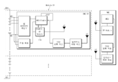
도 3은 본 발명의 일 실시예에 따른 CMC와 BMC의 구성도가 간략히 도시되어 있다. CMC는 배터리 셀과 모듈의 상태를 모니터링/관리 해주는 모듈이고, BMC는 CMC로부터 전달되는 정보를 바탕으로 배터리 상태를 진단/추정/관리 해주는 모듈이다. 3 is a schematic diagram of a CMC and a BMC according to an embodiment of the present invention. CMC is a module that monitors/manages the status of battery cells and modules, and BMC is a module that diagnoses/estimates/manages battery status based on information transmitted from CMC.
각각의 배터리에 연결되는 CMC 모듈은 제1 안테나(a1), 제2 안테나(b1), 임피던스 매칭 회로, 다단 정류 회로, MCU, RF 모듈, 셀 파라미터 측정부 및 전원 회로를 포함한다. The CMC module connected to each battery includes a first antenna a1, a second antenna b1, an impedance matching circuit, a multi-stage rectifying circuit, an MCU, an RF module, a cell parameter measuring unit, and a power supply circuit.
또한, BMC는 제1 안테나(a2), 제2 안테나(b2), MCU, RF 모듈, 다단 정류 회로, 임피던스 매칭 회로를 포함한다. 앞서 설명한 바와 같이, CMC 및 BMC는 다단 정류 회로에 축적된 에너지를 방전시키기 위한 방전회로를 더 포함할 수 있다.In addition, the BMC includes a first antenna a2, a second antenna b2, an MCU, an RF module, a multi-stage rectification circuit, and an impedance matching circuit. As described above, CMC and BMC may further include a discharge circuit for discharging the energy accumulated in the multi-stage rectification circuit.
BMC의 MCU는 RF 모듈로 하여금 제2 주파수를 가지는 RF 신호를 생성하여 제1 안테나(a2)를 이용하여 CMC 모듈로 전송하도록 한다. 즉, BMC의 제어부는 CMC를 대기 상태에서 웨이크업 상태로 천이시키기 위한 웨이크업 신호를 제2 주파수를 가지는 신호로서 생성하여 제1 안테나(a2)를 통하여 CMC로 전송하고, CMC와 일반적인 데이터 송수신을 제1 주파수를 가지는 RF 신호로 수행하도록 한다. CMC의 제1 안테나(a2)를 통하여 전송된 RF 신호는 제2 안테나(b1)에서 수신되어 임피던스 매칭 회로에 의하여 주파수 매칭되어 MCU로 전달된다. The MCU of the BMC causes the RF module to generate an RF signal having a second frequency and transmit it to the CMC module using the first antenna a2. That is, the control unit of the BMC generates a wake-up signal for transitioning the CMC from the standby state to the wake-up state as a signal having a second frequency, transmits it to the CMC through the first antenna a2, and transmits and receives general data to and from the CMC. It is performed with an RF signal having a first frequency. The RF signal transmitted through the first antenna (a2) of the CMC is received from the second antenna (b1) and frequency-matched by an impedance matching circuit and transmitted to the MCU.
제2 주파수를 가지는 신호는 CMC와 BMC가 데이터 통신을 하기 위한 신호가 아니다. 제2 주파수를 가지는 신호는 단지 CMC가 대기 상태에서 웨이크업 상태로 천이되면 되므로, 신호 내에 명령이나 데이터가 포함될 필요는 없다. 대신, 제2 주파수를 가지는 신호를 이용하여 MCU가 웨이크업 상태로 천이될 수 있는 인에이블 신호를 생성하여야 하므로 소정의 에너지 밀도를 가질 필요가 있다. 즉, 제2 주파수를 가지는 신호의 에너지 밀도는 CMC와 BMC가 통신할 때 사용하는 제1 주파수를 가지는 신호의 에너지 밀도보다 커야 한다. 다시 말해, 제2 주파수를 가지는 신호는 데이터의 송신이 아닌 에너지의 전달이 주된 목적이다.The signal having the second frequency is not a signal for CMC and BMC to perform data communication. Since the signal having the second frequency only needs to transition from the standby state to the wake-up state, there is no need to include a command or data in the signal. Instead, it is necessary to have a predetermined energy density because the MCU must generate an enable signal that can transition to a wake-up state using a signal having a second frequency. That is, the energy density of the signal having the second frequency must be greater than the energy density of the signal having the first frequency used when the CMC and the BMC communicate. In other words, a signal having a second frequency is a primary purpose of transmitting energy, not transmitting data.
제2 안테나(b1)가 제1 안테나(a2)로부터 RF 신호를 수신하면, 다단 정류 회로는 전압을 생성한다. 정류 회로는 수신된 RF 신호로 MCU를 웨이크 업 상태로 천이시킬 정도의 전압을 생성하는 것은 어렵게 때문에, 높은 전압 형성을 위해 필요 전압까지 다단으로 구성될 수 있다. When the second antenna b1 receives the RF signal from the first antenna a2, the multi-stage rectifying circuit generates a voltage. The rectifying circuit can be configured in multiple stages up to a required voltage for forming a high voltage because it is difficult to generate a voltage sufficient to transition the MCU to a wake-up state with the received RF signal.
다단 정류 회로는 복수 개의 다이오드와 복수 개의 캐패시터를 포함할 수 있다. 다이오드는 예를 들어, 빠른 정류 및 높은 전압 형성을 위하여 다이오드의 문턱 전압(Vf)이 작고, 상태 천이 속도가 빠른 RF 다이오드일 수 있다.The multi-stage rectification circuit may include a plurality of diodes and a plurality of capacitors. The diode may be, for example, an RF diode having a small threshold voltage (Vf) and a fast state transition rate for rapid rectification and high voltage formation.
정류 다단 회로에서 RF 신호를 수신하여 전압을 생성하여 인에이블 신호를 MCU로 전송하고, MCU에서 이 신호를 감지하여 인에이블된다. MCU는 전원 회로로부터 최소한의 전력만 공급받아 인에이블 신호를 기다린다. 인에이블된 MCU는 각 회로를 인에이블시킨다.The RF signal is received from the rectifying multi-stage circuit to generate a voltage to transmit an enable signal to the MCU, and the MCU detects this signal and is enabled. The MCU receives minimal power from the power supply circuit and waits for the enable signal. Enabled MCUs enable each circuit.
MCU는 RF 모듈을 인에이블시킨다. MCU로부터 인에이블 신호를 받은 전원 회로가 인에이블되어, 배터리로부터 전류를 공급받아 MCU 및 RF 모듈에 전력을 공급한다. The MCU enables the RF module. The power supply circuit that receives the enable signal from the MCU is enabled and receives current from the battery to supply power to the MCU and RF module.
셀 파라미터 측정부는 배터리에 연결되고, 연결된 배터리의 전압 및 온도를 측정한다. 셀 파라미터 측정부는 본 도면에서 하나로 도시되어 있으나, 셀 전압 측정부 및 셀 온도 측정부로 별개의 구성으로 구성될 수도 있다. 셀 파라미터 측정부에서 측정한 셀의 전압 및 온도에 대한 데이터를 MCU로 전송한다. The cell parameter measurement unit is connected to the battery and measures the voltage and temperature of the connected battery. Although the cell parameter measurement unit is shown as one in the figure, the cell voltage measurement unit and the cell temperature measurement unit may be configured in separate configurations. The voltage and temperature of the cell measured by the cell parameter measurement unit are transmitted to the MCU.
셀 파라미터 측정부로부터 셀의 전압 및 온도에 대한 데이터를 수신한 MCU는 해당 셀의 측정 전압 및 온도가 셀의 정상 동작의 범위 내인지 여부를 판단한다. 예를 들어, 측정된 셀의 전압이 제1 임계치보다 크거나 제2 임계치보다 작으면, MCU는 셀의 상태에 문제가 있다고 판단한다. MCU에서 셀의 상태가 문제가 있다고 판단되면, RF 모듈로 하여금 폴트 신호를 생성하도록 한다. 또한, 예를 들어, 측정된 셀의 온도가 제3 임계치보다 크면, MCU는 셀의 상태에 문제가 있다고 판단한다. MCU에서 셀의 상태에 문제가 있다고 판단되면, RF 모듈로 하여금 폴트 신호를 생성하도록 한다. Upon receiving data on the voltage and temperature of the cell from the cell parameter measurement unit, the MCU determines whether the measured voltage and temperature of the cell are within the range of the normal operation of the cell. For example, if the measured cell voltage is greater than the first threshold or less than the second threshold, the MCU determines that there is a problem with the state of the cell. If the MCU determines that the state of the cell is a problem, it causes the RF module to generate a fault signal. Also, for example, if the measured cell temperature is greater than the third threshold, the MCU determines that there is a problem with the cell state. If the MCU determines that there is a problem with the state of the cell, it causes the RF module to generate a fault signal.
RF 모듈은 MCU가 다단 정류 회로에서 생성된 전압을 감지하여 인에이블되면, MCU로부터 인에이블 신호를 수신하여 인에이블된다. 또한, MCU가 셀의 상태에 문제가 있다고 판단하여, MCU로부터 폴트 신호 생성 신호를 수신하면, RF 모듈을 폴트 신호를 생성하여 제1 안테나(a1)로 전송한다. 폴트 신호는 제2 안테나(b1)에서 수신된 RF 신호와는 상이한 주파수를 가진다. The RF module is enabled by receiving an enable signal from the MCU when the MCU detects the voltage generated by the multi-stage rectification circuit and is enabled. In addition, when the MCU determines that there is a problem with the state of the cell and receives a fault signal generation signal from the MCU, the RF module generates a fault signal and transmits it to the first antenna a1. The fault signal has a different frequency from the RF signal received at the second antenna b1.
제1 안테나(a1)는 RF 모듈로부터 폴트 신호를 수신한다. RF 모듈로부터 폴트 신호를 수신한 제1 안테나(a1)는 BMC로 해당 폴트 신호를 전송한다. 폴트 신호는 제1 주파수 및 제2 주파수와는 상이한 제3 주파수를 가진다. 여기서 제3 주파수를 가지는 신호는 데이터가 실려 있는 신호가 아니다. 제3 주파수를 가지는 신호는 단지 BMC에 대하여 배터리 셀에 이상이 발생하였다는 사실만을 통지하면 된다. 따라서 신호 내에 명령이나 데이터가 포함될 필요는 없다. 대신, BMC에서 제3 주파수를 가지는 신호를 수신하였다는 것을 검출 가능해야 하므로, 소정의 에너지 밀도를 가질 필요가 있다. 즉, 제3 주파수를 가지는 신호의 에너지 밀도는 CMC와 BMC가 통신할 때 사용하는 제1 주파수를 가지는 신호의 에너지 밀도보다 커야 한다. 다시 말해, 제3 주파수를 가지는 신호를 송신하는 것은 에너지의 전달을 통하여 특정 이벤트가 발생하였다는 사실을 통지하는 것을 주된 목적으로 한다.The first antenna a1 receives a fault signal from the RF module. The first antenna a1, which has received the fault signal from the RF module, transmits the fault signal to the BMC. The fault signal has a third frequency different from the first frequency and the second frequency. Here, the signal having the third frequency is not a signal carrying data. The signal having the third frequency only needs to notify the BMC that an error has occurred in the battery cell. Therefore, there is no need to include instructions or data in the signal. Instead, it should be possible to detect that a signal having a third frequency has been received by the BMC, so it is necessary to have a predetermined energy density. That is, the energy density of the signal having the third frequency should be greater than the energy density of the signal having the first frequency used when the CMC and the BMC communicate. In other words, the main purpose of transmitting a signal having a third frequency is to notify that a specific event has occurred through the transmission of energy.
BMC의 제2 안테나(b2)에서 CMC로부터 전송된 폴트 신호를 수신한다. 해당 폴트 신호의 주파수는 미리 설정되어 있어, BMC의 임피던스 매칭 회로에 의해서 매칭되는 신호로, 제2 안테나(b2)에서 수신된다. The fault signal transmitted from the CMC is received at the second antenna b2 of the BMC. The frequency of the fault signal is preset, and is a signal matched by the impedance matching circuit of the BMC, and is received by the second antenna b2.
BMC의 제2 안테나(b2)를 통하여 수신된 폴트 신호를 BMC의 MCU에서 감지하여 해당 CMC가 감시하는 배터리 셀에 문제가 생겼음을 판단할 수 있다. 즉, BMC의 제어부는 제2 안테나(b2)로부터 제3 주파수를 가지는 신호를 수신하였을 때, CMC가 모니터링하는 배터리 셀에 이상이 발생하였다고 판단한다. The fault signal received through the second antenna b2 of the BMC can be detected by the MCU of the BMC to determine that a problem has occurred in the battery cell monitored by the corresponding CMC. That is, when the control unit of the BMC receives the signal having the third frequency from the second antenna b2, it determines that an abnormality has occurred in the battery cell monitored by the CMC.
제1 안테나(a1)는 RF 모듈로부터 폴트 신호를 수신한다. RF 모듈로부터 폴트 신호를 수신한 제1 안테나(a1)는 BMC로 폴트 신호를 전송한다. The first antenna a1 receives a fault signal from the RF module. The first antenna a1, which has received the fault signal from the RF module, transmits a fault signal to the BMC.
또한, CMC의 제1 안테나(a1)는 BMC의 제1 안테나(a2)와 제1 주파수를 가지는 RF 신호를 이용하여 일반적인 통신을 수행하는 통신 경로로 사용된다. 그리고 CMC의 제1 안테나(a1)는 BMC의 제2 안테나(b2)로 제3 주파수를 가지는 폴트 신호를 전송한다. 또한, CMC의 제2 안테나(b1)는 BMC의 제1 안테나(a2)로부터 웨이크업 신호를 수신한다. In addition, the first antenna a1 of the CMC is used as a communication path for performing general communication using an RF signal having a first frequency with the first antenna a2 of the BMC. Then, the first antenna a1 of the CMC transmits a fault signal having a third frequency to the second antenna b2 of the BMC. Further, the second antenna b1 of the CMC receives a wake-up signal from the first antenna a2 of the BMC.
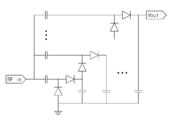
도 4는 본 발명의 일 실시예에 따른 다단 정류 회로의 구현예를 도시한다.4 shows an implementation of a multi-stage rectifying circuit according to an embodiment of the present invention.
RF 신호를 수신하여 전압을 생성하는 다단 정류 회로는, 높은 전압 형성을 위해 필요 전압까지 다단으로 구현이 가능하다. A multi-stage rectifying circuit that generates a voltage by receiving an RF signal can be implemented in multiple stages up to a required voltage for forming a high voltage.
다단 정류 회로에는 복수 개의 다이오드와 복수 개의 캐패시터가 포함된다. RF 신호가 입력되는 입력단에 캐패시터의 일단이 병렬로 연결되어 있으며, 각각의 캐패시터의 타단에는 병렬로 연결되어 있는 다이오드의 일단이 연결된다. 각각의 캐패시터의 타단에 병렬로 연결되어 있는 다이오드 중 하나의 다이오드의 타단에 캐패시터가 또 연결된다. 또한, RF 신호가 입력되는 입력단에 병렬로 연결되는 캐패시터 중 가장 끝 단에 연결되는 캐패시터의 타단에 연결되는 다이오드의 타단에서 전압이 출력된다. The multi-stage rectification circuit includes a plurality of diodes and a plurality of capacitors. One end of the capacitor is connected in parallel to the input terminal to which the RF signal is input, and one end of the diode connected in parallel is connected to the other end of each capacitor. A capacitor is further connected to the other end of one of the diodes connected in parallel to the other end of each capacitor. In addition, a voltage is output from the other end of the diode connected to the other end of the capacitor connected to the far end of the capacitor connected in parallel to the input terminal to which the RF signal is input.
입력부에 병렬로 연결되는 캐패시터의 개수에 따라 다단으로 구현될 수 있으며 원하는 전압의 크기에 따라 다단의 개수가 조절되어 구현될 수 있다. It may be implemented in multiple stages according to the number of capacitors connected in parallel to the input unit, and may be implemented by adjusting the number of multiple stages according to a desired voltage level.
또한, 다단 정류 회로에 포함되는 다이오드는 빠른 정류 및 높은 전압 형성을 위해 문턱 전압이 작고, 상태 천이 속도가 빠른 RF 다이오드일 수 있다.In addition, the diode included in the multi-stage rectification circuit may be an RF diode having a small threshold voltage and a fast state transition rate for fast rectification and high voltage formation.
또한 도 4에 도시된 다단 정류 회로는 일례일 뿐이며 공지된 다른 다단 정류 회로들이 적용될 수도 있을 것이다.Also, the multi-stage rectification circuit illustrated in FIG. 4 is only an example, and other known multi-stage rectification circuits may be applied.
한편, 도 1 내지 도 4에 따른 CMC 및 BMC는 제1 주파수 내지 제3 주파수와 관련하여 다른 방식으로 동작할 수도 있을 것이다. 이하에서는 도 3의 CMC 및 BMC 구성에 기초한 다른 동작 방식에 대해서 설명한다.Meanwhile, the CMC and BMC according to FIGS. 1 to 4 may operate in different ways with respect to the first to third frequencies. Hereinafter, another operation method based on the CMC and BMC configuration of FIG. 3 will be described.
다른 동작 방식의 일 예로서, 제1 주파수 신호 및 제2 주파수 신호의 주파수는 서로 동일할 수도 있다. 데이터 통신이나 명령을 송신할 때 사용하는 신호는 에너지 밀도가 낮아서 회로 부품이 동작하는데 필요한 전압을 생성하는 것이 용이하지 않다. 따라서 CMC의 MCU를 웨이크업 상태로 천이시키기 위하여 인에이블 신호에 사용하는 전압을 생성하기 위하여는, RF 신호가 소정의 에너지 밀도를 가지고 있어야 한다. 따라서 제1 주파수 신호 및 제2 주파수 신호의 주파수를 달리하는 대신에, 각각의 신호가 가지는 에너지 밀도를 달리하여 통신을 위한 신호와 웨이크업을 위한 신호로 구분할 수 있을 것이다.As an example of another operation method, the frequencies of the first frequency signal and the second frequency signal may be the same. Signals used to transmit data or send commands have low energy density, making it difficult to generate the voltage required for circuit components to operate. Therefore, in order to generate the voltage used for the enable signal in order to transition the MCU of the CMC to the wake-up state, the RF signal must have a predetermined energy density. Therefore, instead of different frequencies of the first frequency signal and the second frequency signal, the energy density of each signal may be different to be divided into a signal for communication and a signal for wakeup.
다른 동작 방식의 다른 예로서, 제1 주파수 신호 및 제3 주파수 신호의 주파수는 서로 동일할 수도 있다. 제3 주파수 신호는 폴트 신호로서 데이터를 전송할 필요가 있는 것은 아니며, BMC가 제3 주파수 신호가 수신되었다는 사실만을 파악할 수 있으면 된다. 즉, CMC에서 BMC로 소정의 에너지가 전달되면 된다. 따라서 제3 주파수 신호도, 제2 주파수 신호의 경우와 마찬가지로, 주파수를 달리하는 대신에 각각의 신호가 가지는 에너지 밀도를 달리함으로써 통신을 위한 신호와 폴트 신호를 구분할 수 있을 것이다.As another example of a different operation method, frequencies of the first frequency signal and the third frequency signal may be the same. The third frequency signal is a fault signal and does not need to transmit data, and it is only necessary for the BMC to know that the third frequency signal has been received. That is, a predetermined energy need only be transferred from CMC to BMC. Therefore, as in the case of the second frequency signal, the third frequency signal may be distinguished between a signal for communication and a fault signal by varying the energy density of each signal instead of different frequencies.
이와 같이 제1 주파수 신호와 제2 주파수 신호에서의 주파수를 동일하게 하는 경우 BMC는 하나의 RF 모듈만을 구비하면 되므로 비용 및 설치 공간을 절약할 수 있게 된다. 또한 마찬가지로 제1 주파수 신호와 제3 주파수 신호에서의 주파수를 동일하게 하는 경우 CMC는 하나의 RF 모듈만을 구비하면 되므로 비용 및 설치 공간을 절약할 수 있게 된다.When the frequencies in the first frequency signal and the second frequency signal are the same, the BMC needs only one RF module, thereby saving cost and installation space. Also, if the frequencies of the first frequency signal and the third frequency signal are the same, the CMC only needs to have one RF module, thereby saving cost and installation space.
도 5는 본 발명의 다른 실시예에 따른 셀 관리 제어기의 간략한 구성도이다. 5 is a simplified configuration diagram of a cell management controller according to another embodiment of the present invention.
셀 관리 제어기(100)는 제2 안테나(102), 임피던스 매칭 회로(104), 전압 생성부(106), 전원 회로(108), 셀 파라미터 측정부(110), 구동부(112), RF 모듈(114) 및 제1 안테나(116)를 포함하고 있다. The
여기서, 배터리의 종류는 특별히 한정되지 않으며, 예를 들어 배터리는 리튬 이온 전지, 리튬 폴리머 전지, 니켈 카드뮴 전지, 니켈 수소 전지, 니켈 아연 전지 등으로 구성될 수 있다. Here, the type of the battery is not particularly limited, and for example, the battery may be composed of a lithium ion battery, a lithium polymer battery, a nickel cadmium battery, a nickel hydrogen battery, a nickel zinc battery, or the like.
또한, 배터리는 복수의 전지 셀이 직렬 및/또는 병렬로 연결되어 있는 배터리 모듈로 형성되고, 복수의 배터리 모듈로 직렬 및/또는 병렬로 연결되는 배터리 팩이 형성된다. 배터리는 하나 이상의 배터리 팩을 포함할 수 있다.Further, the battery is formed of a battery module in which a plurality of battery cells are connected in series and/or in parallel, and a battery pack connected in series and/or in parallel with a plurality of battery modules is formed. The battery can include one or more battery packs.
제2 안테나(102)는 외부 장치, 예를 들어 BMC로부터 제2 주파수를 가지는 RF 신호를 수신한다. 제2 안테나(102)에서 수신되는 RF 신호 중 임피던스 매칭 회로(104)에서 매칭이 되는 주파수를 가진 RF 신호가 전압 생성부(108)로 전달된다. 즉, 임피던스 매칭 회로(104)는 제2 안테나(102)를 통하여 수신되는 RF 신호 중 미리 매칭되어 있는 제2 주파수를 가지는 RF 신호를 선별하여 전압 생성부(108)로 전달한다. The
제2 안테나(102)로부터 RF 신호를 수신한 전압 생성부(106)는 수신된 RF 신호를 이용하여 전압을 생성한다. 즉, 전압 생성부(106)는 제2 안테나(102)에서 수신된 제2 주파수를 가지는 RF 신호에 기초하여 전압을 생성한다. 제2 안테나(102)에서 수신하는 제2 주파수를 가지는 RF 신호는 제1 안테나(116)에서 BMC와 통신하기 위하여 주고받는 제1 주파수를 가지는 RF 신호에 비하여 에너지 밀도가 높다. 이러한 제2 주파수를 가지는 RF 신호는 데이터를 포함하지 않는 신호일 수 있다. 즉, 제2 주파수를 가지는 RF 신호는 변조되지 않은 신호일 수 있다. 예를 들어, 제2 주파수를 가지는 RF 신호는 CW(Continuous Wave) 신호일 수 있다. 즉, 제2 주파수를 가지는 RF 신호는 단순히 소정의 에너지 밀도 이상의 에너지를 셀 관리 제어기(100)에 전달하기 위한 신호일 수 있다.The
전압 생성부(106)는 예를 들어, 다단 정류 회로일 수 있다. 다만, 수신된 RF 신호로 구동부(112)를 웨이크업 상태로 천이시킬 정도의 전압을 생성하는 것이 어렵게 때문에, 높은 전압 형성을 위해 필요 전압까지 다단으로 구현될 수 있다. 즉, 다단 정류 회로는 제2 주파수를 가지는 RF 신호로부터 생성되어야 할 전압에 따라 단수가 조절될 수 있다.The
전압 생성부(106)는 다단 정류 회로를 구성하기 위하여 복수 개의 다이오드와 복수 개의 캐패시터를 포함할 수 있다. 다이오드는 예를 들어, 빠른 정류 및 높은 전압 형성을 위하여 다이오드의 문턱 전압(Vf)이 작고, 상태 천이 속도가 빠른 RF 다이오드일 수 있다.The
전압 생성부(106)에서 RF 신호를 수신하여 전압을 생성하면, 전원 회로(108)에서 이를 감지하여 인에이블된다. 즉, 전압 생성부(106)에서 생성된 전압이 전원 회로(108)를 인에이블시키는 인에이블 신호가 된다. 전원 회로는 전압 생성부에서 생성된 전압이 입력될 때 구동부(112)에 인에이블 신호를 인가한다. 인에이블된 전원 회로(108)는 각 회로를 인에이블시킨다. 전원 회로(108)가 인에이블되어 셀 관리 제어기(100) 내의 각각의 회로 구성, 구동부(112), RF 모듈(114)에 전력을 공급한다. When the
전원 회로(108)로부터 전력을 공급받은 구동부(112)는 전원 회로(108)로부터 인가되는 인에이블 신호에 기초하여 웨이크업 상태로 천이한다. 웨이크업된 구동부(112)는 셀 파라미터 측정부(110)에 제어신호를 전송하여, 셀의 전압 또는 온도를 측정하도록 한다. The
셀 파라미터 측정부(110)는 배터리에 연결되고, 구동부(112)에서 수신한 제어 신호에 기초하여 배터리 셀의 상태를 나타내는 파라미터를 측정한다. 배터리 셀의 상태를 나타내는 파라미터는 전압 또는 온도 중 적어도 하나일 수 있다. 셀 파라미터 측정부(110)는 본 도면에서 하나로 도시되어 있으나, 셀 전압 측정부 및 셀 온도 측정부로 별개의 구성으로 구성될 수도 있다. 셀 파라미터 측정부(110)에서 측정한 셀의 전압 및 온도에 대한 데이터를 구동부(112)로 전송한다.The cell
셀 파라미터 측정부(110)로부터 수신한 배터리 셀의 파라미터 값에 기초하여, 구동부(112)는 배터리 셀의 이상 여부를 판단한다. 즉, 셀 파라미터 측정부(110)로부터 셀의 전압 및 온도에 대한 데이터를 수신한 구동부(112)는, 해당 셀의 측정 전압 및 온도가 셀의 정상 동작의 범위 내인지 여부를 판단한다. 예를 들어, 측정된 셀의 전압이 제1 임계치보다 크거나 제2 임계치보다 작으면, 구동부(112)는 셀의 상태에 문제가 있다고 판단한다. 구동부(112)에서 셀의 상태가 문제가 있다고 판단되면, RF 모듈(114)로 하여금 폴트 신호를 생성하도록 한다. 또한, 예를 들어, 측정된 셀의 온도가 제3 임계치보다 크면, 구동부(112)는 셀의 상태에 문제가 있다고 판단한다. 구동부(112)에서 셀의 상태에 문제가 있다고 판단되면, RF 모듈(114)로 하여금 폴트 신호를 생성하도록 한다. 즉, 배터리 셀에 이상이 발생하였다고 판단된 경우, 외부 장치로 배터리 셀의 이상 상태를 나타내는 폴트 신호를 상기 제1 주파수와는 상이한 제3 주파수로 전송한다.Based on the parameter value of the battery cell received from the cell
이때, 제3 주파수로 전송하는 신호 또한 제2 주파수의 신호와 마찬가지로, BMC와 통신하기 위하여 주고받는 제1 주파수를 가지는 RF 신호에 비하여 에너지 밀도가 높다. 그리고 제3 주파수를 가지는 RF 신호인 폴트 신호는 데이터를 포함하지 않는 신호일 수 있다. 즉, 제3 주파수를 가지는 RF 신호는 변조되지 않은 신호일 수 있다. 예를 들어, 제3 주파수를 가지는 RF 신호는 CW(Continuous Wave) 신호일 수 있다. 즉, 폴트 신호는 단순히 소정의 에너지 밀도 이상의 에너지를 BMC에 전달하기 위한 신호일 수 있다.At this time, the signal transmitted at the third frequency, as well as the signal at the second frequency, has a higher energy density than the RF signal having the first frequency exchanged to communicate with the BMC. The fault signal, which is an RF signal having a third frequency, may be a signal that does not contain data. That is, the RF signal having the third frequency may be an unmodulated signal. For example, the RF signal having a third frequency may be a CW (Continuous Wave) signal. That is, the fault signal may simply be a signal for transmitting energy above a predetermined energy density to the BMC.
RF 모듈(114)은 전원 회로(108)로부터 전원이 공급되고, 구동부(112)에 의하여 인에이블된다. 또한, 구동부(112)가 셀의 상태에 문제가 있다고 판단하여, 구동부(112)로부터 폴트 신호 생성 신호를 수신하면, RF 모듈(114)은 제3 주파수를 가지는 폴트 신호를 생성하여 제1 안테나(116)로 전송한다. The
제1 안테나(116)는 RF 모듈(114)로부터 폴트 신호를 수신한다. RF 모듈(114)로부터 폴트 신호를 수신한 제1 안테나(116)는 외부 장치, 예를 들어 BMC로 폴트 신호를 전송한다. 제1 안테나(116)는 또한 BMC로 폴트 신호를 전송하는 것 이외에도, BMC와 일반적인 통신을 하는 안테나이다.The
또한, 도시하지는 않았으나, 다단 정류 회로에 축적된 에너지를 방전시키기 위한 방전회로를 더 포함할 수 있다. 방전회로는 다단 정류 회로에 축적된 에너지를 주기적으로 혹은 소정의 조건을 만족시킬 때(예를 들어, 축적된 에너지가 기준치 이상일 때) 방전시킨다.Also, although not shown, a discharge circuit for discharging energy accumulated in the multi-stage rectification circuit may be further included. The discharge circuit discharges the energy accumulated in the multi-stage rectifying circuit periodically or when a predetermined condition is satisfied (for example, when the accumulated energy is greater than or equal to a reference value).
도 6은 본 발명의 다른 실시예에 따른 배터리 상태 모니터링 방법의 간략한 순서도이다. 6 is a simplified flowchart of a battery condition monitoring method according to another embodiment of the present invention.
셀 관리 제어기(100)는 제2 안테나(b1)를 통하여 RF 신호를 수신한 후에 동작을 하기 때문에, RF 신호를 수신하기 전에 BMC로부터 신호를 수신하기 위하여 주기적으로 깨어날 필요가 없다. Since the
셀 관리 제어기(100)는 평상시 대기 상태에 있다가, 제2 안테나(102)가 외부 장치, 예를 들어 BMC로부터 RF 신호를 수신한다(S500).The
제2 안테나(102)에서 수신되는 RF 신호 중 임피던스 매칭 회로(104)에 의하여 주파수가 매칭되는 RF 신호만 전압 생성부(106)로 전달된다. Of the RF signals received from the
제2 안테나(102)에서 BMC로부터 수신된 RF 신호는 전압 생성부(106)로 전달된다. 제2 안테나(102)로부터 RF 신호를 수신한 전압 생성부(106)는 전원 회로(108)를 웨이크업 상태로 천이시키기 위한 전압을 생성한다(S502). 이 때 생성된 전압을 기초로 인에이블 신호를 전원 회로(108)로 인가한다. The RF signal received from the BMC at the
전압 생성부(106)는 예를 들어, 다단 정류 회로일 수 있다. 다만, 수신된 RF 신호로 전원 회로(108)를 웨이크업 상태로 천이시킬 정도의 전압을 생성하는 것이 어렵기 때문에, 높은 전압 형성을 위해 필요 전압까지 다단으로 구현할 수 있다. The
전압 생성부(106)는 다단 정류 회로를 구성하기 위하여 복수 개의 다이오드와 복수 개의 캐패시터를 포함할 수 있다. 다이오드는 예를 들어, 빠른 정류 및 높은 전압 형성을 위하여 다이오드의 문턱 전압(Vf)이 작고, 상태 천이 속도가 빠른 RF 다이오드일 수 있다.The
전압 생성부(106)에서 RF 신호를 수신하여 전압을 생성하면, 이를 전원 회로(108)에서 이를 수신하여 인에이블된다(S504). 전압 생성부(106)에서 생성된 전압에 의하여 인에이블된 전원회로(108)는 셀 관리 제어기(100) 내의 각 회로에 전력을 공급하면서 인에이블시킨다(S506). 구동부(112)는 예를 들어, 셀 관리 제어기(100) 내의 구성을 각각 제어하는 MCU일 수 있다.When the
인에이블 신호를 수신하여 웨이크업 상태로 천이된 구동부(112)가 파라미터 측정부(110)로 셀 전압 및 온도 측정 신호(제어 신호)를 전송하여, 셀 전압 및 온도를 측정하도록 한다(S508). 구동부(112)에 의하여 구동된 셀 파라미터 측정부는 셀의 전압 및 온도를 측정한다(S510). 셀 파라미터 측정부(110)는 배터리 셀과 연결되어 배터리 셀의 전압 및 온도를 측정한다. 셀 파라미터 측정부(110)가 배터리 셀의 전압 및 온도를 측정하여, 전압 및 온도 데이터를 구동부(112)로 전송한다.The
셀 파라미터 측정부(110)에서 측정된 셀의 전압 및 온도 데이터를 수신한 구동부(112)는 수신한 셀의 전압 및 온도 데이터를 기초로 배터리 셀에 문제가 발생했는지를 판단한다(S512).The
예를 들어, 측정된 셀의 전압의 제1 임계치보다 크거나 제2 임계치보다 작으면, 구동부(112)는 셀의 상태에 문제가 있다고 판단한다. 또는, 측정된 셀의 온도가 제3 임계치보다 크면, 구동부(112)는 셀의 상태에 문제가 있다고 판단한다.For example, if the measured cell voltage is greater than the first threshold or less than the second threshold, the
구동부(112)에서 셀의 상태가 문제가 있다고 판단되면, RF 모듈(114)로 하여금 제3 주파수를 가지는 폴트 신호를 생성하여, 제1 안테나(116)를 통하여 폴트 신호를 외부 장치로 전송하도록 한다(S514). 이 폴트 신호는 미리 외부 장치, 예를 들어 BMC에서 임피던스 매칭이 되는 신호이다.When the
구동부(112)에서 셀의 상태가 문제가 없다고 판단되면, 구동을 종료하고 다시 대기모드로 들어간다. 다만, 셀의 상태가 문제가 없다고 판단될 때에도, 구동부(112)는 RF 모듈(114)로 하여금 폴트 신호와는 다른 주파수의 신호를 생성하도록 할 수는 있을 것이다. 이는 미리 설정할 수 있다.If the
도 7은 본 발명의 다른 실시예에 따른 CMC와 BMC의 구성도가 간략히 도시되어 있다. 7 is a schematic diagram of a CMC and a BMC according to another embodiment of the present invention.
각각의 배터리에 연결되는 CMC 모듈은 제1 안테나(a1), 제2 안테나(b1), 임피던스 매칭 회로, 다단 정류 회로, MCU, RF 모듈, 셀 파라미터 측정부 및 전원 회로를 포함한다.The CMC module connected to each battery includes a first antenna a1, a second antenna b1, an impedance matching circuit, a multi-stage rectifying circuit, an MCU, an RF module, a cell parameter measuring unit, and a power supply circuit.
또한, BMC는 제1 안테나(a2), 제2 안테나(b2), MCU, RF 모듈, 다단 정류 회로, 임피던스 매칭 회로를 포함한다. 앞서 설명한 바와 같이, CMC 및 BMC는 다단 정류 회로에 축적된 에너지를 방전시키기 위한 방전회로를 더 포함할 수 있다.In addition, the BMC includes a first antenna a2, a second antenna b2, an MCU, an RF module, a multi-stage rectification circuit, and an impedance matching circuit. As described above, CMC and BMC may further include a discharge circuit for discharging the energy accumulated in the multi-stage rectification circuit.
BMC의 MCU는 RF 모듈로 하여금 제2 주파수를 가지는 RF 신호를 생성하여 제1 안테나(a2)를 이용하여 CMC 모듈로 전송하도록 한다. 즉, BMC의 제어부는 CMC를 대기 상태에서 웨이크업 상태로 천이시키기 위한 웨이크업 신호를 제2 주파수를 가지는 신호로서 생성하여 제1 안테나(a2)를 통하여 CMC로 전송하고, CMC와 데이터 송수신을 제1 주파수를 가지는 RF 신호로 수행하도록 한다. RF 신호는 미리 정해진 주파수를 가진다. CMC의 제1 안테나(a2)를 통하여 전송된 RF 신호는 제2 안테나(b1)에서 수신되고, 임피던스 매칭 회로에서 주파수 매칭이 되는 신호를 선별하여 다단 정류 회로로 전달된다. The MCU of the BMC causes the RF module to generate an RF signal having a second frequency and transmit it to the CMC module using the first antenna a2. That is, the controller of the BMC generates a wake-up signal for transitioning the CMC from the standby state to the wake-up state as a signal having a second frequency, transmits it to the CMC through the first antenna a2, and transmits and receives data to and from the CMC. It is to be performed with an RF signal having 1 frequency. The RF signal has a predetermined frequency. The RF signal transmitted through the first antenna (a2) of the CMC is received from the second antenna (b1), and the signal that is frequency-matched by the impedance matching circuit is selected and transmitted to the multi-stage rectifying circuit.
앞선 실시예에서와 마찬가지로 제2 주파수를 가지는 신호는 CMC와 BMC가 데이터 통신을 하기 위한 신호가 아니다. 제2 주파수를 가지는 신호는 단지 CMC가 대기 상태에서 웨이크업 상태로 천이되면 되므로, 신호 내에 명령이나 데이터가 포함될 필요는 없다. 대신, 제2 주파수를 가지는 신호를 이용하여 전원회로가 웨이크업 상태로 천이될 수 있는 인에이블 신호를 생성하여야 하므로 소정의 에너지 밀도를 가질 필요가 있다. 즉, 제2 주파수를 가지는 신호의 에너지 밀도는 CMC와 BMC가 통신할 때 사용하는 제1 주파수를 가지는 신호의 에너지 밀도보다 커야 한다. 다시 말해, 제2 주파수를 가지는 신호는 데이터의 송신이 아닌 에너지의 전달이 주된 목적이다.As in the previous embodiment, the signal having the second frequency is not a signal for data communication between CMC and BMC. Since the signal having the second frequency only needs to transition from the standby state to the wake-up state, there is no need to include a command or data in the signal. Instead, it is necessary to have a predetermined energy density because the power circuit must generate an enable signal that can transition to a wake-up state using a signal having a second frequency. That is, the energy density of the signal having the second frequency should be greater than the energy density of the signal having the first frequency used when the CMC and the BMC communicate. In other words, a signal having a second frequency is a primary purpose of transmitting energy, not transmitting data.
제2 안테나(b1)가 제1 안테나(a2)로부터 RF 신호를 수신하면, 다단 정류 회로는 전압을 생성한다. 정류 회로는 수신된 RF 신호로 전원 회로를 깨울 정도의 전압을 생성하는 것은 어렵게 때문에, 높은 전압 형성을 위해 필요 전압까지 다단으로 구성될 수 있다. When the second antenna b1 receives the RF signal from the first antenna a2, the multi-stage rectifying circuit generates a voltage. Since the rectifying circuit is difficult to generate a voltage sufficient to wake up the power supply circuit with the received RF signal, it can be configured in multiple stages up to a required voltage for high voltage formation.
다단 정류 회로는 복수 개의 다이오드와 복수 개의 캐패시터를 포함할 수 있다. 다이오드는 예를 들어, 빠른 정류 및 높은 전압 형성을 위하여 다이오드의 문턱 전압(Vf)이 작고, 상태 천이 속도가 빠른 RF 다이오드일 수 있다.The multi-stage rectification circuit may include a plurality of diodes and a plurality of capacitors. The diode may be, for example, an RF diode having a small threshold voltage (Vf) and a fast state transition rate for rapid rectification and high voltage formation.
정류 다단 회로에서 RF 신호를 수신하여 전압을 생성하면, 전원회로에서 이를 인에이블 신호로 감지하여(또는 생성된 전압을 인가받아) 인에이블되어 각 회로에 전력을 공급한다. 즉, 전원 회로가 각 회로의 구성 MCU, RF 모듈을 인에이블시킨다. When a voltage is generated by receiving an RF signal from a rectifying multi-stage circuit, the power circuit senses it as an enable signal (or receives the generated voltage) and is enabled to supply power to each circuit. That is, the power supply circuit enables the component MCU and RF module of each circuit.
전원 회로로부터 인에이블 신호를 수신한 MCU는 셀 파라미터 측정부로 하여금 셀의 전압 및 온도를 측정하도록 한다. The MCU that receives the enable signal from the power supply circuit causes the cell parameter measurement unit to measure the voltage and temperature of the cell.
셀 파라미터 측정부는 배터리에 연결되고, 연결된 배터리의 전압 및 온도를 측정한다. 셀 파라미터 측정부는 본 도면에서 하나로 도시되어 있으나, 셀 전압 측정부 및 셀 온도 측정부로 별개의 구성으로 구성될 수도 있다. 셀 파라미터 측정부에서 측정한 셀의 전압 및 온도에 대한 데이터를 MCU로 전송한다. The cell parameter measurement unit is connected to the battery and measures the voltage and temperature of the connected battery. Although the cell parameter measurement unit is shown as one in the figure, the cell voltage measurement unit and the cell temperature measurement unit may be configured in separate configurations. The voltage and temperature of the cell measured by the cell parameter measurement unit are transmitted to the MCU.
셀 파라미터 측정부로부터 셀의 전압 및 온도에 대한 데이터를 수신한 MCU는 해당 셀의 측정 전압 및 온도가 셀의 정상 동작의 범위 내인지 여부를 판단한다. 예를 들어, 측정된 셀의 전압이 제1 임계치보다 크거나 제2 임계치보다 작으면, MCU는 셀의 상태에 문제가 있다고 판단한다. MCU에서 셀의 상태가 문제가 있다고 판단되면, RF 모듈로 하여금 폴트 신호를 생성하도록 한다. 또한, 예를 들어, 측정된 셀의 온도가 제3 임계치보다 크면, MCU는 셀의 상태에 문제가 있다고 판단한다. MCU에서 셀의 상태에 문제가 있다고 판단되면, RF 모듈로 하여금 폴트 신호를 생성하도록 한다.Upon receiving data on the voltage and temperature of the cell from the cell parameter measurement unit, the MCU determines whether the measured voltage and temperature of the cell are within the range of the normal operation of the cell. For example, if the measured cell voltage is greater than the first threshold or less than the second threshold, the MCU determines that there is a problem with the state of the cell. If the MCU determines that the state of the cell is a problem, it causes the RF module to generate a fault signal. Also, for example, if the measured cell temperature is greater than the third threshold, the MCU determines that there is a problem with the cell state. If the MCU determines that there is a problem with the state of the cell, it causes the RF module to generate a fault signal.
RF 모듈은 MCU가 전원 회로로부터 인에이블 신호를 수신하여, 다시 RF 모듈로 인에이블 신호를 전송하면 인에이블된다. 또한, MCU가 셀의 상태에 문제가 있다고 판단하여, MCU로부터 폴트 신호 생성 신호를 수신하면, RF 모듈을 제3 주파수를 가지는 폴트 신호를 생성하여 제1 안테나(a1)로 전송한다.The RF module is enabled when the MCU receives an enable signal from the power supply circuit and sends an enable signal back to the RF module. In addition, when the MCU determines that there is a problem in the state of the cell and receives a fault signal generation signal from the MCU, the RF module generates a fault signal having a third frequency and transmits it to the first antenna a1.
제1 안테나(a1)는 RF 모듈로부터 폴트 신호를 수신한다. RF 모듈로부터 폴트 신호를 수신한 제1 안테나(a1)는 BMC로 해당 폴트 신호를 전송한다. 여기서 제3 주파수를 가지는 신호는 데이터가 실려 있는 신호가 아니다. 제3 주파수를 가지는 신호는 단지 BMC에 대하여 배터리 셀에 이상이 발생하였다는 사실만을 통지하면 된다. 따라서 신호 내에 명령이나 데이터가 포함될 필요는 없다. 대신, BMC에서 제3 주파수를 가지는 신호를 수신하였다는 것을 검출 가능해야 하므로, 소정의 에너지 밀도를 가질 필요가 있다. 즉, 제3 주파수를 가지는 신호의 에너지 밀도는 CMC와 BMC가 통신할 때 사용하는 제1 주파수를 가지는 신호의 에너지 밀도보다 커야 한다. 다시 말해, 제3 주파수를 가지는 신호를 송신하는 것은 에너지의 전달을 통하여 특정 이벤트가 발생하였다는 사실을 통지하는 것을 주된 목적으로 한다.The first antenna a1 receives a fault signal from the RF module. The first antenna a1, which has received the fault signal from the RF module, transmits the fault signal to the BMC. Here, the signal having the third frequency is not a signal carrying data. The signal having the third frequency only needs to notify the BMC that an error has occurred in the battery cell. Therefore, there is no need to include instructions or data in the signal. Instead, it should be possible to detect that a signal having a third frequency has been received by the BMC, so it is necessary to have a predetermined energy density. That is, the energy density of the signal having the third frequency should be greater than the energy density of the signal having the first frequency used when the CMC and the BMC communicate. In other words, the main purpose of transmitting a signal having a third frequency is to notify that a specific event has occurred through the transmission of energy.
BMC의 제2 안테나(b2)에서 CMC에서 전송된 폴트 신호를 수신한다. 해당 폴트 신호의 주파수는 미리 설정되어 있어, BMC의 임피던스 매칭 회로에 의해서 매칭되는 신호로, 제2 안테나(b2)에서 수신된다. The fault signal transmitted from the CMC is received from the second antenna b2 of the BMC. The frequency of the fault signal is preset, and is a signal matched by the impedance matching circuit of the BMC, and is received by the second antenna b2.
BMC의 제2 안테나(b2)를 통하여 수신된 폴트 신호를 BMC의 MCU에서 감지하여 해당 CMC가 감시하는 배터리 셀에 문제가 생겼음을 판단할 수 있다. 즉, BMC의 제어부는 제2 안테나(b2)로부터 제3 주파수를 가지는 신호를 수신하였을 때, CMC가 모니터링하는 배터리 셀에 이상이 발생하였다고 판단한다. 폴트 신호는 에너지 전달을 통한 이벤트 검출의 통지가 목적이므로, BMC의 MCU는 제2 안테나(b2)로부터 미리 설정된 기준 이상의 에너지를 갖는 제3 주파수의 신호를 수신하는 것을 검출하는 경우, CMC가 모니터링하는 배터리 셀에 이상이 발생하였다고 판단할 수 있다.The fault signal received through the second antenna b2 of the BMC can be detected by the MCU of the BMC to determine that a problem has occurred in the battery cell monitored by the corresponding CMC. That is, when the control unit of the BMC receives the signal having the third frequency from the second antenna b2, it determines that an abnormality has occurred in the battery cell monitored by the CMC. Since the fault signal is for the purpose of notification of event detection through energy transfer, the BMC's MCU monitors the CMC when it detects that the second antenna b2 receives a signal of a third frequency having an energy above a predetermined reference. It can be determined that an abnormality has occurred in the battery cell.
또한, CMC의 제1 안테나(a1)는 BMC의 제1 안테나(a2)와 제1 주파수를 가지는 RF 신호를 이용하여 일반적인 통신을 수행하는 통신 경로로 사용된다. 그리고 CMC의 제1 안테나(a1)는 BMC의 제2 안테나(b2)로 제3 주파수를 가지는 폴트 신호를 전송한다. 또한, CMC의 제2 안테나(b1)는 BMC의 제2 안테나(b2)로부터 웨이크업 신호인 RF 신호를 수신한다.In addition, the first antenna a1 of the CMC is used as a communication path for performing general communication using an RF signal having a first frequency with the first antenna a2 of the BMC. Then, the first antenna a1 of the CMC transmits a fault signal having a third frequency to the second antenna b2 of the BMC. In addition, the second antenna b1 of the CMC receives the RF signal, which is a wake-up signal, from the second antenna b2 of the BMC.
도 1 내지 도 4에 따른 실시예의 경우와 마찬가지로, 도 5 내지 도 7에 따른 CMC 및 BMC가 제1 주파수 내지 제3 주파수가 서로 동일한 주파수인 경우에도 동작할 수 있음을 이해할 수 있을 것이다. 즉, 제1 주파수 내지 제3 주파수가 서로 동일한 주파수인 경우, 제2 주파수의 신호와 제3 주파수의 신호는 에너지 밀도를 달리함으로써 본 발명의 목적을 달성할 수 있을 것이다.As in the case of the embodiment according to FIGS. 1 to 4, it will be understood that the CMC and BMC according to FIGS. 5 to 7 can operate even when the first to third frequencies are the same frequency. That is, when the first to third frequencies are the same frequency, the signals of the second frequency and the signals of the third frequency may achieve the object of the present invention by varying the energy density.
추가적으로, 도 4 및 도 7에 도시한 바와 같이, BMC가 복수의 CMC를 관리하는 경우에 다음과 같은 변형예를 고려할 수 있다.Additionally, as illustrated in FIGS. 4 and 7, the following modification may be considered when the BMC manages a plurality of CMCs.
복수의 CMC 각각은 동일한 구성을 갖는다. 다만, CMC에서 자신이 모니터링하는 배터리 셀에 이상이 발생한 것을 검출한 경우, BMC로 전송하는 폴트 신호의 주파수를 서로 다르게 설정한다. 즉, 폴트 신호 전송을 위한 제3 주파수의 신호에 있어서의 제3 주파수가 각 CMC마다 서로 상이하다.Each of the plurality of CMCs has the same configuration. However, when the CMC detects that an abnormality has occurred in the battery cell it monitors, the frequency of the fault signal transmitted to the BMC is set differently. That is, the third frequency in the signal of the third frequency for the transmission of the fault signal is different for each CMC.
이와 함께, BMC는 복수의 CMC와 제1 주파수로 통신을 수행하는 것에 더하여 복수의 CMC 중 어느 CMC로부터 폴트 신호가 수신되는지를 모니터링 해야 한다. 즉, 어느 CMC에서 폴트 신호가 송신되는지 알 수 없기 때문에, 대상이되는 모든 주파수를 스캔해야 한다. 따라서, CMC의 MCU는 임피던스 매칭 회로의 임피던스를 조정하는 등 하여, 복수의 CMC들이 폴트 신호를 송신하게 되는 서로 상이한 제3 주파수들을 포함하는 주파수 범위를 스캐닝한다.In addition to this, in addition to performing communication on a first frequency with a plurality of CMCs, the BMC should monitor which of the plurality of CMCs a fault signal is received from. That is, since it is not known which fault signal is transmitted from which CMC, all target frequencies need to be scanned. Accordingly, the MCU of the CMC scans a frequency range including different third frequencies where a plurality of CMCs transmit a fault signal, such as by adjusting the impedance of the impedance matching circuit.
이러한 구성으로 인하여 BMC는 어느 CMC에서 이상이 발생하였는지를 즉시 파악할 수 있게 된다. 즉, BMC가 폴트 신호를 수신한 주파수를 파악할 수 있기 때문에 폴트 신호에 다른 정보가 포함되어 있지 않아도 BMC는 폴트 신호를 송신한 CMC를 특정할 수 있게 된다.Due to this configuration, the BMC can immediately identify which CMC has an abnormality. That is, since the BMC can grasp the frequency at which the fault signal is received, the BMC can specify the CMC that has transmitted the fault signal even if the fault signal does not include other information.
이상에서 본 발명은 비록 한정된 실시예와 도면에 의해 설명되었으나, 본 발명은 이것에 의해 한정되지 않으며, 본 발명이 속하는 기술분야에서 통상의 지식을 가진 자에 의해 본 발명의 기술사상과 아래에 기재될 특허청구범위의 균등범위 내에서 다양한 실시가 가능함은 물론이다.Although the present invention has been described above by way of limited examples and drawings, the present invention is not limited by this, and is described below by the person skilled in the art to which the present invention pertains, and the technical idea of the present invention. Of course, various implementations are possible within the equal scope of the claims to be made.
100 셀 관리 제어기
102 제2 안테나
104 임피더스 매칭 회로
106 전압 생성부
108 전원 회로
110 셀 파라미터 측정부
112 구동부
114 RF 모듈
116 제1 안테나100 cell management controller
102 second antenna
104 Impedance Matching Circuit
106 voltage generator
108 power circuit
110 cell parameter measurement unit
112 Drive
114 RF module
116 first antenna
Claims (16)
상기 외부 장치로부터의 제2 주파수의 신호를 수신 가능한 제2 안테나;
상기 제2 안테나에서 수신된 상기 제2 주파수의 신호에 기초하여 전압을 생성하는 전압 생성부;
상기 전압 생성부에서 생성된 전압에 기초한 신호를 인에이블 신호로서 인가받는 구동부; 및
상기 구동부로부터의 제어신호에 기초하여 배터리 셀의 상태를 나타내는 파라미터를 측정하는 셀 파라미터 측정부;를 포함하며,
상기 인에이블 신호에 기초하여 상기 구동부가 대기 상태에서 웨이크업 상태로 천이하는 셀 관리 제어기.A first antenna capable of communicating with an external device using a first frequency;
A second antenna capable of receiving a signal of a second frequency from the external device;
A voltage generator configured to generate a voltage based on the signal of the second frequency received from the second antenna;
A driving unit receiving a signal based on the voltage generated by the voltage generating unit as an enable signal; And
It includes; a cell parameter measuring unit for measuring a parameter indicating the state of the battery cell based on the control signal from the driving unit;
A cell management controller that transitions from a standby state to a wake-up state based on the enable signal.
상기 제2 주파수의 신호는 상기 제1 주파수의 신호보다 에너지 밀도가 더 높은 것을 특징으로 하는 셀 관리 제어기.The method according to claim 1,
The cell management controller, characterized in that the signal of the second frequency has a higher energy density than the signal of the first frequency.
상기 제2 안테나에서 상기 제2 주파수의 신호를 수신 가능하도록 임피던스를 매칭시키는 임피던스 매칭 회로를 더 포함하는 셀 관리 제어기.The method according to claim 1,
And an impedance matching circuit that matches impedance to receive the signal of the second frequency from the second antenna.
상기 전압 생성부에 축적되는 에너지를 방전시키기 위한 방전회로를 더 포함하는 셀 관리 제어기.The method according to claim 3,
A cell management controller further comprising a discharge circuit for discharging energy accumulated in the voltage generator.
상기 구동부는 상기 셀 파라미터 측정부로부터 수신한 상기 배터리 셀의 파라미터 값에 기초하여 상기 배터리 셀의 이상 여부를 판단하고,
상기 배터리 셀에 이상이 발생하였다고 판단된 경우, 상기 외부 장치에 상기 배터리 셀의 이상 상태를 나타내는 폴트 신호를 제3 주파수로 전송하는 것을 특징으로 하는, 셀 관리 제어기.The method according to claim 1,
The driving unit determines whether the battery cell is abnormal based on the parameter value of the battery cell received from the cell parameter measurement unit,
When it is determined that an error has occurred in the battery cell, the cell management controller, characterized in that for transmitting the fault signal indicating the abnormal state of the battery cell to the external device at a third frequency.
상기 제3 주파수의 신호는 상기 제1 주파수의 신호보다 에너지 밀도가 더 높은 것을 특징으로 하는 셀 관리 제어기.The method according to claim 5,
The cell management controller, characterized in that the signal of the third frequency has a higher energy density than the signal of the first frequency.
상기 폴트 신호는 상기 제1 안테나를 통하여 전송되는 것을 특징으로 하는, 셀 관리 제어기.The method according to claim 5,
The fault signal is transmitted through the first antenna, characterized in that the cell management controller.
상기 구동부로 전력을 공급하는 전원 회로를 더 포함하고,
상기 전원 회로는 상기 전압 생성부에서 생성된 전압이 입력될 때 상기 구동부에 인에이블 신호를 인가하고,
상기 구동부는 상기 전원 회로로부터 인가되는 상기 인에이블 신호에 기초하여 웨이크업 상태로 천이하는 것을 특징으로 하는 셀 관리 제어기.The method according to claim 1,
Further comprising a power supply circuit for supplying power to the driving unit,
The power circuit applies an enable signal to the driver when the voltage generated by the voltage generator is input,
The driving unit is a cell management controller, characterized in that the transition to the wake-up state based on the enable signal applied from the power circuit.
상기 구동부로 전력을 공급하는 전원 회로를 더 포함하고,
상기 전원 회로는 상기 구동부에 전력을 상시 공급하며,
상기 구동부는 상기 전압 생성부에서 생성된 상기 전압을 상기 인에이블 신호로서 인가받는 것을 특징으로 하는 셀 관리 제어기.The method according to claim 1,
Further comprising a power supply circuit for supplying power to the driving unit,
The power supply circuit constantly supplies power to the driving unit,
The driving unit is a cell management controller, characterized in that the voltage generated by the voltage generation unit is applied as the enable signal.
상기 외부 장치를 대기 상태에서 웨이크업 상태로 천이시키기 위한 웨이크업 신호를 상기 제2 주파수의 신호로서 생성하여 상기 제1 안테나를 통하여 상기 외부 장치로 전송하고, 상기 외부 장치와의 데이터 송수신을 상기 제1 주파수로 수행하는 제어부;를 포함하며,
상기 제어부는 상기 제2 주파수의 신호의 에너지 밀도가 상기 제1 주파수의 신호의 에너지 밀도보다 크도록 상기 제1 주파수의 신호 및 제2 주파수의 신호를 생성하는 배터리 관리 제어기.A first antenna capable of communicating with an external device using a first frequency and a second frequency; And
A wake-up signal for transitioning the external device from a standby state to a wake-up state is generated as a signal of the second frequency and transmitted to the external device through the first antenna, and data transmission/reception with the external device is performed. Includes a control unit to perform at one frequency;
The controller generates a signal of the first frequency and a signal of the second frequency such that the energy density of the signal of the second frequency is greater than the energy density of the signal of the first frequency.
상기 외부 장치로부터 제3 주파수의 신호를 수신 가능한 제2 안테나를 더 포함하고,
상기 제어부는 상기 제2 안테나로부터 상기 제3 주파수의 신호를 수신하였을 때, 상기 외부 장치가 모니터링하는 배터리 셀에 이상이 발생하였다고 판단하는 배터리 관리 제어기.The method according to claim 10,
Further comprising a second antenna capable of receiving a signal of a third frequency from the external device,
The control unit determines that an abnormality has occurred in a battery cell monitored by the external device when the signal of the third frequency is received from the second antenna.
상기 제어부는 상기 제2 안테나로부터 미리 설정된 기준 이상의 에너지를 갖는 제3 주파수의 신호를 수신하는 것을 검출하는 경우, 상기 외부 장치가 모니터링하는 배터리 셀에 이상이 발생하였다고 판단하는 배터리 관리 제어기.The method according to claim 11,
The control unit determines that an abnormality has occurred in a battery cell monitored by the external device when detecting that a signal having a third frequency having a predetermined energy or higher is received from the second antenna.
상기 제2 안테나에서 상기 제3 주파수의 신호를 수신 가능하도록 임피던스를 매칭시키는 임피던스 매칭 회로; 및
상기 임피던스 매칭 회로를 통하여 수신되는 신호에 의하여 축적되는 에너지를 방전시키기 위한 방전회로를 더 포함하는 배터리 관리 제어기.The method according to claim 11,
An impedance matching circuit that matches impedance to be able to receive the signal of the third frequency from the second antenna; And
And a discharge circuit for discharging energy accumulated by the signal received through the impedance matching circuit.
상기 셀 관리 제어기와 통신하여 상기 셀 관리 제어기로부터 상기 배터리 셀에 대하여 측정한 파라미터값을 수신하는 배터리 관리 제어기;를 포함하며,
상기 복수의 셀 관리 제어기 각각은,
상기 배터리 관리 제어기와 제1 주파수를 이용하여 통신 가능하도록 구성된 제1 안테나와, 상기 배터리 관리 제어기로부터제2 주파수의 신호를 수신 가능하도록 구성된 제2 안테나와, 상기 제2 안테나에서 수신하는 상기 제2 주파수의 신호에 기초하여 전압을 생성하도록 구성된 전압 생성부와, 상기 전압 생성부에서 생성된 전압에 기초한 신호를 인에이블 신호로서 인가받도록 구성된 구동부와, 상기 구동부로부터의 제어신호에 기초하여 상기 배터리 셀의 상태를 나타내는 파라미터를 측정하도록 구성된 셀 파라미터 측정부를 포함하며,
상기 인에이블 신호에 기초하여 상기 구동부가 대기 상태에서 웨이크업 상태로 천이하는, 배터리 관리 시스템.A plurality of cell management controllers monitoring the state of the battery cells; And
It includes; a battery management controller for communicating with the cell management controller to receive a parameter value measured for the battery cell from the cell management controller;
Each of the plurality of cell management controllers,
A first antenna configured to enable communication with the battery management controller using a first frequency, a second antenna configured to receive a signal of a second frequency from the battery management controller, and the second antenna received from the second antenna. A voltage generating unit configured to generate a voltage based on a frequency signal, a driving unit configured to receive a signal based on the voltage generated by the voltage generating unit as an enable signal, and the battery cell based on a control signal from the driving unit Cell parameter measurement unit configured to measure the parameter indicating the state of the,
The battery management system, wherein the driving unit transitions from a standby state to a wake-up state based on the enable signal.
상기 복수의 셀 관리 제어기 각각에서,
상기 구동부는 상기 셀 파라미터 측정부로부터 수신한 상기 배터리 셀의 파라미터 값에 기초하여 상기 배터리 셀의 이상 여부를 판단하고,
상기 배터리 셀에 이상이 발생하였다고 판단된 경우, 상기 배터리 관리 제어기에 상기 배터리 셀의 이상 상태를 나타내는 폴트 신호를 미리 설정된 제3 주파수로 전송하며,
상기 복수의 셀 관리 제어기들은 상기 미리 설정된 제3 주파수가 서로 상이한 주파수인 것을 특징으로 하는, 배터리 관리 시스템.The method according to claim 14,
In each of the plurality of cell management controller,
The driving unit determines whether the battery cell is abnormal based on the parameter value of the battery cell received from the cell parameter measurement unit,
When it is determined that an abnormality has occurred in the battery cell, a fault signal indicating the abnormal state of the battery cell is transmitted to the battery management controller at a preset third frequency,
The plurality of cell management controllers, characterized in that the preset third frequency is a different frequency, the battery management system.
상기 배터리 관리 제어기는,
상기 복수의 셀 관리 제어기로부터의 폴트 신호를 수신하기 위하여 상기 복수의 셀 관리 제어기들이 폴트 신호를 송신하는 서로 상이한 제3 주파수들을 포함하는 주파수 범위를 스캐닝하는 것을 특징으로 하는 배터리 관리 시스템.The method according to claim 15,
The battery management controller,
A battery management system, characterized in that the plurality of cell management controllers scan a frequency range including different third frequencies that transmit a fault signal to receive a fault signal from the plurality of cell management controllers.
Applications Claiming Priority (2)
| Application Number | Priority Date | Filing Date | Title |
|---|---|---|---|
| KR1020180157150 | 2018-12-07 | ||
| KR20180157150 | 2018-12-07 |
Publications (2)
| Publication Number | Publication Date |
|---|---|
| KR20200070122A true KR20200070122A (en) | 2020-06-17 |
| KR102379225B1 KR102379225B1 (en) | 2022-03-28 |
Family
ID=70973956
Family Applications (1)
| Application Number | Title | Priority Date | Filing Date |
|---|---|---|---|
| KR1020190161341A KR102379225B1 (en) | 2018-12-07 | 2019-12-06 | Apparatus and method for managing battery |
Country Status (6)
| Country | Link |
|---|---|
| US (1) | US11296514B2 (en) |
| EP (1) | EP3764507A4 (en) |
| JP (1) | JP7107487B2 (en) |
| KR (1) | KR102379225B1 (en) |
| CN (1) | CN111712987B (en) |
| WO (1) | WO2020117000A1 (en) |
Cited By (1)
| Publication number | Priority date | Publication date | Assignee | Title |
|---|---|---|---|---|
| WO2023234572A1 (en) * | 2022-05-31 | 2023-12-07 | 주식회사 엘지에너지솔루션 | Apparatus and method for diagnosing abnormality of battery cell |
Families Citing this family (3)
| Publication number | Priority date | Publication date | Assignee | Title |
|---|---|---|---|---|
| DE102020115333A1 (en) * | 2019-06-17 | 2020-12-17 | Silicon Works Co., Ltd. | Wireless battery management system, wireless communication nodes and data transfer methods |
| KR20210092488A (en) * | 2020-01-16 | 2021-07-26 | 에스케이이노베이션 주식회사 | Battery management system |
| CN115601948A (en) * | 2022-09-29 | 2023-01-13 | 中国第一汽车股份有限公司(Cn) | Wireless control method and system for lithium ion battery pack and vehicle |
Citations (4)
| Publication number | Priority date | Publication date | Assignee | Title |
|---|---|---|---|---|
| US20100176202A1 (en) * | 2005-10-18 | 2010-07-15 | Teraoka Koji | Noncontact data carrier |
| US20140347014A1 (en) * | 2010-11-02 | 2014-11-27 | Navitas Solutions | Fault tolerant wireless battery area network for a smart battery management system |
| US20160294019A1 (en) * | 2013-12-16 | 2016-10-06 | Hitachi, Ltd. | Battery system and battery cell management device |
| EP3098895A1 (en) * | 2014-01-20 | 2016-11-30 | Hitachi Automotive Systems, Ltd. | Power supply control system, power supply control apparatus, and power supply control method |
Family Cites Families (22)
| Publication number | Priority date | Publication date | Assignee | Title |
|---|---|---|---|---|
| JPH08139635A (en) | 1994-11-07 | 1996-05-31 | Yokogawa Electric Corp | Radio communication equipment |
| US6928559B1 (en) * | 1997-06-27 | 2005-08-09 | Broadcom Corporation | Battery powered device with dynamic power and performance management |
| US7969043B2 (en) * | 2007-11-05 | 2011-06-28 | O2 Micro, Inc. | Power management systems with multiple power sources |
| JP2010081716A (en) | 2008-09-25 | 2010-04-08 | Toshiba Corp | Battery information obtaining device |
| JP2010142083A (en) * | 2008-12-15 | 2010-06-24 | Toshiba Corp | Battery pack system |
| US20110051641A1 (en) * | 2009-08-30 | 2011-03-03 | Yang Pan | Low Power Consumption Wireless Sensory and Data Transmission System |
| JP5663748B2 (en) | 2010-03-31 | 2015-02-04 | エリーパワー株式会社 | Management system, management apparatus, management unit and selection method |
| WO2011125103A1 (en) | 2010-04-02 | 2011-10-13 | 株式会社 東芝 | Radio apparatus |
| US9559530B2 (en) | 2010-11-02 | 2017-01-31 | Navitas Solutions | Fault tolerant wireless battery area network for a smart battery management system |
| CN103270666B (en) * | 2010-11-02 | 2018-01-30 | 纳维达斯解决方案有限公司 | Wireless battery Local Area Network for intelligent battery management |
| US9000935B2 (en) * | 2011-03-31 | 2015-04-07 | Elite Power Solutions Llc | Battery management system |
| JP5677171B2 (en) | 2011-04-07 | 2015-02-25 | 株式会社日立製作所 | Battery module and battery system including the same |
| KR101856663B1 (en) | 2011-06-03 | 2018-05-10 | 에스케이이노베이션 주식회사 | Secondary battery sub Unit, Secondary battery management system and Method for exchanging information in multi-pack parallel structure using the same |
| WO2013051157A1 (en) | 2011-10-07 | 2013-04-11 | 日立ビークルエナジー株式会社 | Battery monitoring system, host controller, and battery monitoring device |
| KR101276930B1 (en) | 2011-12-29 | 2013-06-19 | 전영환 | Security system |
| US10870360B2 (en) | 2013-02-12 | 2020-12-22 | Cps Technology Holdings Llc | Battery monitoring network |
| KR102155199B1 (en) | 2013-12-23 | 2020-09-11 | 삼성전자주식회사 | Matching circuit, NFC device and electronic system including the same |
| JP6134397B2 (en) | 2014-02-14 | 2017-05-24 | 株式会社日立製作所 | Battery control system, battery system |
| KR102176853B1 (en) | 2016-07-22 | 2020-11-10 | 주식회사 엘지화학 | Battery wireless control system and method |
| KR102148060B1 (en) | 2016-08-18 | 2020-08-25 | 주식회사 엘지화학 | Appatarus and method for identifying the position of the battery cell module |
| KR20180037733A (en) | 2016-10-05 | 2018-04-13 | 삼성전자주식회사 | Method for controlling temperature of battery, and battery management apparatus and system |
| KR102202614B1 (en) * | 2017-09-19 | 2021-01-12 | 주식회사 엘지화학 | Battery management system and a battery pack including the same |
-
2019
- 2019-12-06 WO PCT/KR2019/017211 patent/WO2020117000A1/en unknown
- 2019-12-06 US US16/969,620 patent/US11296514B2/en active Active
- 2019-12-06 EP EP19893934.0A patent/EP3764507A4/en active Pending
- 2019-12-06 KR KR1020190161341A patent/KR102379225B1/en active IP Right Grant
- 2019-12-06 CN CN201980012949.4A patent/CN111712987B/en active Active
- 2019-12-06 JP JP2020550120A patent/JP7107487B2/en active Active
Patent Citations (5)
| Publication number | Priority date | Publication date | Assignee | Title |
|---|---|---|---|---|
| US20100176202A1 (en) * | 2005-10-18 | 2010-07-15 | Teraoka Koji | Noncontact data carrier |
| US20140347014A1 (en) * | 2010-11-02 | 2014-11-27 | Navitas Solutions | Fault tolerant wireless battery area network for a smart battery management system |
| US20160294019A1 (en) * | 2013-12-16 | 2016-10-06 | Hitachi, Ltd. | Battery system and battery cell management device |
| EP3098895A1 (en) * | 2014-01-20 | 2016-11-30 | Hitachi Automotive Systems, Ltd. | Power supply control system, power supply control apparatus, and power supply control method |
| JP6181211B2 (en) * | 2014-01-20 | 2017-08-16 | 日立オートモティブシステムズ株式会社 | Power supply control system and power supply control apparatus |
Cited By (1)
| Publication number | Priority date | Publication date | Assignee | Title |
|---|---|---|---|---|
| WO2023234572A1 (en) * | 2022-05-31 | 2023-12-07 | 주식회사 엘지에너지솔루션 | Apparatus and method for diagnosing abnormality of battery cell |
Also Published As
| Publication number | Publication date |
|---|---|
| EP3764507A1 (en) | 2021-01-13 |
| WO2020117000A1 (en) | 2020-06-11 |
| US11296514B2 (en) | 2022-04-05 |
| KR102379225B1 (en) | 2022-03-28 |
| EP3764507A4 (en) | 2021-04-07 |
| CN111712987A (en) | 2020-09-25 |
| CN111712987B (en) | 2023-08-08 |
| US20210028631A1 (en) | 2021-01-28 |
| JP7107487B2 (en) | 2022-07-27 |
| JP2021516945A (en) | 2021-07-08 |
Similar Documents
| Publication | Publication Date | Title |
|---|---|---|
| KR102379225B1 (en) | Apparatus and method for managing battery | |
| US8736229B2 (en) | Battery control circuit for reducing power consumption | |
| US10319218B2 (en) | Wireless battery system, and wireless system | |
| US8330421B2 (en) | Battery pack manager | |
| US9722446B2 (en) | Wireless power transmitter, wireless power receiver, and control methods thereof | |
| US20110001485A1 (en) | Energy management for an electronic device | |
| CN101126795A (en) | Battery performance testing system | |
| JP2013219936A (en) | Power storage device, control method of power storage device, and power supply device | |
| CN202616826U (en) | An active balance testing device of a battery | |
| EP3471186A1 (en) | Battery system with battery cell internal cell supervision circuits | |
| KR20210053103A (en) | Appratus and method for monitoring battery | |
| US20200264236A1 (en) | Building management system with remaining battery energy estimation for wireless devices | |
| JP2010200579A (en) | Storage management system | |
| TWI641945B (en) | Sensing device and control method | |
| KR20210114758A (en) | Battery management system and controlling method of the same | |
| KR102340097B1 (en) | Method and apparatus for managing a battery | |
| CN107919817B (en) | Temperature measuring device and electromagnetic heating device | |
| US20240145798A1 (en) | Distributed battery management system and battery record device thereof | |
| KR20190142152A (en) | Energy storage system including System BMS | |
| WO2023125012A1 (en) | Battery management system and battery pack | |
| TWI601968B (en) | Battery monitoring module for vehicle, monitoring method, battery module and vehicle thereof | |
| KR20230174322A (en) | Battery cell controller providing function of blocking internal leakage current | |
| CN113595176A (en) | Lithium battery charging dynamic protection system based on experience function and wireless data transmission | |
| CN117638277A (en) | Battery, management system, management method, and readable medium | |
| CN113489102A (en) | Metering equipment and power supply control method thereof |
Legal Events
| Date | Code | Title | Description |
|---|---|---|---|
| E902 | Notification of reason for refusal | ||
| AMND | Amendment | ||
| E601 | Decision to refuse application | ||
| X091 | Application refused [patent] | ||
| AMND | Amendment | ||
| X701 | Decision to grant (after re-examination) | ||
| GRNT | Written decision to grant |