KR20200069539A - Safety syringe - Google Patents
Safety syringe Download PDFInfo
- Publication number
- KR20200069539A KR20200069539A KR1020180156694A KR20180156694A KR20200069539A KR 20200069539 A KR20200069539 A KR 20200069539A KR 1020180156694 A KR1020180156694 A KR 1020180156694A KR 20180156694 A KR20180156694 A KR 20180156694A KR 20200069539 A KR20200069539 A KR 20200069539A
- Authority
- KR
- South Korea
- Prior art keywords
- cylinder
- injection
- withdrawal
- packing
- hole
- Prior art date
Links
Images


Classifications
-
- A—HUMAN NECESSITIES
- A61—MEDICAL OR VETERINARY SCIENCE; HYGIENE
- A61M—DEVICES FOR INTRODUCING MEDIA INTO, OR ONTO, THE BODY; DEVICES FOR TRANSDUCING BODY MEDIA OR FOR TAKING MEDIA FROM THE BODY; DEVICES FOR PRODUCING OR ENDING SLEEP OR STUPOR
- A61M5/00—Devices for bringing media into the body in a subcutaneous, intra-vascular or intramuscular way; Accessories therefor, e.g. filling or cleaning devices, arm-rests
- A61M5/178—Syringes
- A61M5/31—Details
- A61M5/32—Needles; Details of needles pertaining to their connection with syringe or hub; Accessories for bringing the needle into, or holding the needle on, the body; Devices for protection of needles
- A61M5/3205—Apparatus for removing or disposing of used needles or syringes, e.g. containers; Means for protection against accidental injuries from used needles
- A61M5/321—Means for protection against accidental injuries by used needles
- A61M5/322—Retractable needles, i.e. disconnected from and withdrawn into the syringe barrel by the piston
- A61M5/3232—Semi-automatic needle retraction, i.e. in which triggering of the needle retraction requires a deliberate action by the user, e.g. manual release of spring-biased retraction means
-
- A—HUMAN NECESSITIES
- A61—MEDICAL OR VETERINARY SCIENCE; HYGIENE
- A61M—DEVICES FOR INTRODUCING MEDIA INTO, OR ONTO, THE BODY; DEVICES FOR TRANSDUCING BODY MEDIA OR FOR TAKING MEDIA FROM THE BODY; DEVICES FOR PRODUCING OR ENDING SLEEP OR STUPOR
- A61M5/00—Devices for bringing media into the body in a subcutaneous, intra-vascular or intramuscular way; Accessories therefor, e.g. filling or cleaning devices, arm-rests
- A61M5/178—Syringes
- A61M5/19—Syringes having more than one chamber, e.g. including a manifold coupling two parallelly aligned syringes through separate channels to a common discharge assembly
-
- A—HUMAN NECESSITIES
- A61—MEDICAL OR VETERINARY SCIENCE; HYGIENE
- A61M—DEVICES FOR INTRODUCING MEDIA INTO, OR ONTO, THE BODY; DEVICES FOR TRANSDUCING BODY MEDIA OR FOR TAKING MEDIA FROM THE BODY; DEVICES FOR PRODUCING OR ENDING SLEEP OR STUPOR
- A61M5/00—Devices for bringing media into the body in a subcutaneous, intra-vascular or intramuscular way; Accessories therefor, e.g. filling or cleaning devices, arm-rests
- A61M5/178—Syringes
- A61M5/28—Syringe ampoules or carpules, i.e. ampoules or carpules provided with a needle
-
- A—HUMAN NECESSITIES
- A61—MEDICAL OR VETERINARY SCIENCE; HYGIENE
- A61M—DEVICES FOR INTRODUCING MEDIA INTO, OR ONTO, THE BODY; DEVICES FOR TRANSDUCING BODY MEDIA OR FOR TAKING MEDIA FROM THE BODY; DEVICES FOR PRODUCING OR ENDING SLEEP OR STUPOR
- A61M5/00—Devices for bringing media into the body in a subcutaneous, intra-vascular or intramuscular way; Accessories therefor, e.g. filling or cleaning devices, arm-rests
- A61M5/178—Syringes
- A61M5/31—Details
- A61M5/32—Needles; Details of needles pertaining to their connection with syringe or hub; Accessories for bringing the needle into, or holding the needle on, the body; Devices for protection of needles
- A61M5/3205—Apparatus for removing or disposing of used needles or syringes, e.g. containers; Means for protection against accidental injuries from used needles
- A61M5/321—Means for protection against accidental injuries by used needles
- A61M5/322—Retractable needles, i.e. disconnected from and withdrawn into the syringe barrel by the piston
- A61M5/3221—Constructional features thereof, e.g. to improve manipulation or functioning
-
- A—HUMAN NECESSITIES
- A61—MEDICAL OR VETERINARY SCIENCE; HYGIENE
- A61M—DEVICES FOR INTRODUCING MEDIA INTO, OR ONTO, THE BODY; DEVICES FOR TRANSDUCING BODY MEDIA OR FOR TAKING MEDIA FROM THE BODY; DEVICES FOR PRODUCING OR ENDING SLEEP OR STUPOR
- A61M5/00—Devices for bringing media into the body in a subcutaneous, intra-vascular or intramuscular way; Accessories therefor, e.g. filling or cleaning devices, arm-rests
- A61M5/50—Devices for bringing media into the body in a subcutaneous, intra-vascular or intramuscular way; Accessories therefor, e.g. filling or cleaning devices, arm-rests having means for preventing re-use, or for indicating if defective, used, tampered with or unsterile
-
- A—HUMAN NECESSITIES
- A61—MEDICAL OR VETERINARY SCIENCE; HYGIENE
- A61M—DEVICES FOR INTRODUCING MEDIA INTO, OR ONTO, THE BODY; DEVICES FOR TRANSDUCING BODY MEDIA OR FOR TAKING MEDIA FROM THE BODY; DEVICES FOR PRODUCING OR ENDING SLEEP OR STUPOR
- A61M5/00—Devices for bringing media into the body in a subcutaneous, intra-vascular or intramuscular way; Accessories therefor, e.g. filling or cleaning devices, arm-rests
- A61M5/178—Syringes
- A61M5/31—Details
- A61M5/32—Needles; Details of needles pertaining to their connection with syringe or hub; Accessories for bringing the needle into, or holding the needle on, the body; Devices for protection of needles
- A61M5/3205—Apparatus for removing or disposing of used needles or syringes, e.g. containers; Means for protection against accidental injuries from used needles
- A61M2005/3206—Needle or needle hub disconnecting devices forming part of or being attached to the hub or syringe body
-
- A—HUMAN NECESSITIES
- A61—MEDICAL OR VETERINARY SCIENCE; HYGIENE
- A61M—DEVICES FOR INTRODUCING MEDIA INTO, OR ONTO, THE BODY; DEVICES FOR TRANSDUCING BODY MEDIA OR FOR TAKING MEDIA FROM THE BODY; DEVICES FOR PRODUCING OR ENDING SLEEP OR STUPOR
- A61M5/00—Devices for bringing media into the body in a subcutaneous, intra-vascular or intramuscular way; Accessories therefor, e.g. filling or cleaning devices, arm-rests
- A61M5/178—Syringes
- A61M5/31—Details
- A61M5/32—Needles; Details of needles pertaining to their connection with syringe or hub; Accessories for bringing the needle into, or holding the needle on, the body; Devices for protection of needles
- A61M5/3205—Apparatus for removing or disposing of used needles or syringes, e.g. containers; Means for protection against accidental injuries from used needles
- A61M5/321—Means for protection against accidental injuries by used needles
- A61M5/322—Retractable needles, i.e. disconnected from and withdrawn into the syringe barrel by the piston
- A61M5/3221—Constructional features thereof, e.g. to improve manipulation or functioning
- A61M2005/3231—Proximal end of needle captured or embedded inside piston head, e.g. by friction or hooks
-
- A—HUMAN NECESSITIES
- A61—MEDICAL OR VETERINARY SCIENCE; HYGIENE
- A61M—DEVICES FOR INTRODUCING MEDIA INTO, OR ONTO, THE BODY; DEVICES FOR TRANSDUCING BODY MEDIA OR FOR TAKING MEDIA FROM THE BODY; DEVICES FOR PRODUCING OR ENDING SLEEP OR STUPOR
- A61M2205/00—General characteristics of the apparatus
- A61M2205/27—General characteristics of the apparatus preventing use
- A61M2205/273—General characteristics of the apparatus preventing use preventing reuse, e.g. of disposables
Abstract
Description
본 발명은 안전주사기에 관한 것으로, 더욱 상세하게는 주사액과 주사제가 분리된 상태로 보관될 수 있도록 이중 챔버를 구비하며, 주사 후 주사바늘에 의한 사고 발생을 방지할 수 있는 이중격실 사전충진 안전주사기에 관한 것이다. The present invention relates to a safety syringe, and more specifically, a double-chamber pre-filled safety syringe capable of preventing accidents caused by an injection needle after injection and having a double chamber so that the injection solution and the injection agent can be stored in separate states. It is about.
일반적으로 주사기는 주사액을 환자의 체내에 주입하거나, 환자의 혈관에서 혈액 또는 체내의 체액을 채취하는데 사용되는 것으로, 주사액이나 채취한 혈액 또는 체액이 수용될 수 있는 실린더와, 실린더의 전방에 마련되어 환자의 체내로 삽입되는 주사바늘, 주사액을 주입하거나 혈액 또는 체액을 실린더 내부로 유입시키기 위해 실린더 내에서 이동할 수 있는 패킹부재와, 패킹부재를 움직일 수 있도록 실린더의 외부로 연장되어 있는 패킹로드로 구성된다. In general, a syringe is used to inject an injection solution into a patient's body or to collect blood or body fluid from a patient's blood vessel, and a cylinder in which the injection solution or the collected blood or body fluid can be accommodated and a patient provided in front of the cylinder It consists of an injection needle inserted into the body of the body, a packing member that can be moved within the cylinder to inject injection fluid or to inject blood or body fluid into the cylinder, and a packing rod that extends outside the cylinder to move the packing member. .
한편, 주사기를 통해 주사액을 체내에 주사할 때 유리 앰플에 들어 있거나 고무 마개가 달려있는 작은 유리병안쪽에 담겨 있는 약물을 주사기 안으로 옮기기 위해서는 유리 앰플의 상단부를 절단하고 절단된 부분을 통해 주사 바늘을 집어넣어 주사할 약물을 흡입하게 된다. On the other hand, when the injection solution is injected into the body through a syringe, in order to transfer the drug contained in the glass ampoule or the inside of the vial with a rubber stopper into the syringe, the upper portion of the glass ampoule is cut and the injection needle is cut through the cut. The drug is injected and inhaled.
이렇게 사용된 주사기의 주사 바늘은 보호캡을 씌운 후 폐기처분하게 되는데, 주사기의 사용 후, 보호캡을 씌우는 과정에서, 또는 취급 과정에서 의사나 간호사가 주사바늘에 찔리는 경우가 종종 발생되며, 또한 주사기의 폐기 처분 과정에서도 주사바늘에 씌워진 보호캡이 분리되어 폐기 처리자도 주사 바늘에 찔리는 경우가 발생한다.The injection needle of the syringe used in this way is disposed of after the protective cap is put on, and after the use of the syringe, in the process of putting on the protective cap, or during handling, a doctor or nurse is often stabbed in the needle, and also the syringe Even in the process of disposal, the protective cap on the needle is removed, and the disposal agent is also stabbed in the needle.
사용된 주사바늘에 의사나 간호사 또는 폐기처리자가 찔려 환자의 전염성 병원균이 전파되는 문제가 있었다. There was a problem in which the infectious pathogen of a patient was transmitted by a doctor, nurse, or waste treatment agent being stabbed in the used needle.
이러한 취급상의 안전문제로 인해 다양한 안전주사기가 개발되었다. Due to these safety issues, various safety syringes have been developed.
하지만 종래의 안전주사기들은 구조적으로 복잡하거나 사용이 불편해 병·의원에서 사용이 저조한 실정이므로, 사용 편의성이 뛰어나고 안전하게 처리할 수 있는 안전주사기의 개발이 필요하다. However, since conventional safety syringes are structurally complicated or inconvenient to use, they are poorly used in hospitals and clinics, and thus, it is necessary to develop a safety syringe that is excellent in convenience and can be safely handled.
본 발명은 상기 문제점을 해결하기 위해 창출된 것으로, 이 종의 주사제가 충진되어 신속하고 간단하게 이 종의 주사제를 혼합 및 주사할 수 있으며, 주사 완료 후 사용된 주사바늘이 실린더의 내부로 삽입되어 주사 후 취급 또는 폐기과정에서 취급자가 주사바늘에 찔리는 사고를 방지할 수 있는 이점이 있다. The present invention was created to solve the above problems, and the injection of this species is filled to quickly and simply mix and inject the injection of this species, and the injection needle used after the injection is completed is inserted into the cylinder. There is an advantage in that the operator can prevent an accident of being stuck in an injection needle during handling or disposal after injection.
본 발명에 따른 이중격실 사전충진 안전주사기는 주사제가 주입되는 내부공간을 가지며, 선단부에 주사제가 토출될 수 있도록 토출홀이 형성되어 있는 실린더와, 상기 실린더의 내부에 삽입되어 상기 실린더의 내부에 충진된 주사제를 상기 토출홀 측으로 가압할 수 있는 가압패킹 및 상기 가압패킹으로부터 상기 실린더의 외부로 연장되는 연장로드를 포함하는 가압부와, 상기 토출홀을 통해 토출되는 주사제를 환자의 피부 속으로 주입하도록 삽입되는 주사바늘과, 상기 실린더의 선단부에 설치되어 상기 주사바늘을 지지하는 헤드유닛을 포함하되, 상기 헤드유닛은 상기 실린더의 외측에 고정 설치되는 외부체결부재와, 상기 실린더의 내부에 삽입되어 상기 외부체결부재에 의해 상기 실린더의 외부로 이탈하는 것은 차단되며, 주사제의 주입 후 상기 가압부와 연결되는 제1 인출부재와, 상기 제1 인출부재에 체결되며 상기 주사바늘이 연결되고, 상기 실린더의 내부로 진입을 허용하거나 차단하도록 상기 외부체결부재에 걸리거나 걸림이 해제될 수 있는 인입차단부를 포함하는 제2 인출부재를 포함한다.The double-compartment pre-filled safety syringe according to the present invention has an inner space in which an injection agent is injected, and a cylinder in which a discharge hole is formed so that the injection agent is discharged at the tip, and is inserted into the cylinder and filled in the cylinder. Pressurizing portion including a pressure packing that can pressurize the injected agent toward the discharge hole and an extension rod extending from the pressure packing to the outside of the cylinder, and to inject the injection agent discharged through the discharge hole into the patient's skin It includes an injection needle to be inserted, and a head unit installed at the front end of the cylinder to support the injection needle, wherein the head unit is fixed to the outside of the cylinder and an external fastening member, and is inserted inside the cylinder to Departing from the outside of the cylinder is blocked by an external fastening member, and after injection of the injection agent, the first withdrawal member connected to the pressurization part is fastened to the first withdrawal member, and the injection needle is connected to the cylinder. It includes a second withdrawal member including an inlet blocking portion that can be caught or released from the external fastening member to allow or block entry into the interior.
상기 외부체결부재는 상기 실린더의 선단부 외경에 대응하는 내경의 중공이 형성되어 있으며, 하단부는 상기 실린더의 선단부에 외부로 돌출되게 형성된 걸림턱에 걸리는 걸이부가 형성되어 있으며, 상기 제1 인출부재는 상기 실린더의 내경에 대응하는 외경의 원통부재로 하단부에는 상기 가압패킹으로부터 연장되는 인출걸이부재가 통과할 수 있는 통과홀이 형성되며, 상단부에는 상기 외부체결부재의 상면 내측에 형성된 차단홈에 삽입되어 상기 제1 인출부재가 상기 외부체결부재에 대하여 회전하는 것을 차단하기 위한 회전방지돌기가 원주방향을 따라 소정간격 이격되어 상방으로 소정길이 돌출되게 형성되어 있고, 상기 제2 인출부재에는 상기 통과홀을 통과해 진입한 인출걸이부재가 삽입 및 결합되는 걸이홈이 형성되는 것이 바람직하다.The outer fastening member is formed with a hollow having an inner diameter corresponding to the outer diameter of the leading end of the cylinder, and a lower end is formed with a hooking portion that engages a locking jaw formed to protrude outward at the leading end of the cylinder, and the first drawing member is the A cylindrical member having an outer diameter corresponding to the inner diameter of the cylinder is formed with a through hole through which a withdrawal hook member extending from the pressurized packing can pass, and inserted into a blocking groove formed inside the upper surface of the outer fastening member at the upper end. The anti-rotation protrusion for blocking the first withdrawal member from rotating with respect to the external fastening member is formed to protrude a predetermined length upward at a predetermined interval along the circumferential direction, and passes through the through hole to the second withdrawal member. It is preferable that a hook groove into which the withdrawal hook member is inserted and coupled is formed.
상기 제2 인출부재에 형성된 인입차단부는 상기 제2 인출부재의 외주면으로부터 외측으로 소정길이 돌출되어 있고, 상기 외부체결부재는 상면에 상기 제2 인출부재가 실린더의 전방을 향해 돌출될 수 있도록 관통홀이 형성되되, 상기 관통홀을 중심으로 일측에는 상기 인입차단부가 통과해 외부체결부재의 내부로 이동이 허용될 수 있는 통과허용홈이 형성되어 있고, 상기 통과허용홈을 제외한 나머지 영역은 상기 인입차단부가 통과할 수 없도록 내경이 상기 제2 인출부재의 외경에 대응하도록 형성될 수 있다. The withdrawal blocking portion formed on the second withdrawal member protrudes a predetermined length outward from the outer circumferential surface of the second withdrawal member, and the outer fastening member has a through hole so that the second withdrawing member protrudes toward the front of the cylinder on the upper surface. This is formed, the through-hole is formed on one side of the through-hole is allowed to pass through the inlet blocking portion is allowed to move into the interior of the external fastening member, the rest of the area except for the through-hole is blocking the inlet The inner diameter may be formed to correspond to the outer diameter of the second drawing member so that no additional passage can be made.
상기 통과허용홈과 이격되는 위치에는 상기 인입차단부에 의해 제2 인출부재가 실린더의 내측으로 진입하는 것을 차단하는 위치의 진입차단부가 형성되고, 상기 통과허용홈과 진입차단부의 양측 가장자리에는 해당 위치로 진입한 인입차단부가 통과허용홈 또는 진입차단부에서 벗어나는 것을 방지하기 위한 이탈방지돌기가 마련되되, 상기 이탈방지돌기는 상기 통과허용홈 및 진입차단부의 가장자리에서 멀어질수록 점점 돌출높이가 낮아지도록 경사지게 형성되는 것이 바람직하다.An entry blocking portion is formed at a position spaced apart from the through allowable groove to block the second withdrawal member from entering the inside of the cylinder by the intake blocking portion, and the corresponding location is located at both edges of the through allowable groove and the entry blocking portion. Departure prevention protrusions are provided to prevent the ingress blocking portion entering into the passage allowable groove or the entry blocking portion, and the protrusion preventing protrusion gradually decreases as the distance from the edge of the passage permitting groove and the entry blocking portion increases. It is preferably formed obliquely.
상기 제2 인출부재의 하부에는 실린더의 내부에 충진된 주사제가 상기 주사바늘로 이동하는 이동통로의 연통구가 형성되어 있으며, 상기 인입차단부가 상기 진입차단부에 위치할 때, 상기 연통구가 개방되고, 상기 인입차단부가 상기 통과허용홈에 위치할 때, 연통구가 폐쇄되도록 형성되는 것이 바람직하다.A communication opening of a movement passage through which the injection agent filled in the cylinder moves to the injection needle is formed at a lower portion of the second withdrawal member, and when the intake blocking portion is located in the entry blocking portion, the communication opening is opened. When the inlet blocking portion is located in the passage allowable groove, it is preferable that the communication port is formed to be closed.
상기 연장로드는 상기 주사바늘 및 헤드유닛의 제1 인출부재와 제2 인출부재가 상기 실린더의 내부로 진입하여 상기 주사바늘이 외부로 노출되지 않은 상태에 있을 때, 상기 실린더의 후단부에 대응하는 위치에서 절단할 수 있는 절단가이드부가 형성되는 것이 바람직하다.The extension rod corresponds to the rear end of the cylinder when the first and second withdrawal members of the injection needle and the head unit enter the interior of the cylinder and the injection needle is not exposed to the outside. It is preferable to form a cutting guide part that can be cut at a position.
상기 인출걸이부재는 전단부가 전방으로 연장될수록 외경이 점점 좁아지는 절두원추형으로 형성되어 있고, 상기 걸이홈은 상기 인출걸이부재가 내부로 진입하는 것은 허용하도록 신축변형이 가능하며, 상기 인출걸이부재가 내부로 진입한 상태에서 인출걸이부재만 인출되는 것은 차단하도록 직경이 상기 인출걸이부재의 하단부 직경보다 상대적으로 작게 형성되는 것이 바람직하다.The withdrawal hook member is formed in a truncated cone shape in which the outer diameter becomes narrower as the front end portion extends forward, and the hook groove is elastically deformable to allow the withdrawal hook member to enter the interior, and the withdrawal hook member is It is preferable that the diameter is formed to be relatively smaller than the diameter of the lower end of the withdrawal hook member so as to block the withdrawal hook member from being pulled out while entering the inside.
상기 실린더의 내부에 설치되어 상기 실린더의 내부 공간을 전방부공간과 후방부공간으로 분할하기 위한 분할패킹을 더 구비하되, 상기 분할패킹은 중앙부에 주사제가 통과할 수 있는 연통홀이 형성되어 있고, 신축변형이 가능한 재질로 형성되며, 상기 실린더의 내주면에는 후방부에 상기 분할패킹이 진입할 때, 상기 연통홀이 폐쇄될 수 있도록 상기 분할패킹이 압축 변형되도록 유도하는 내부돌출구간이 형성되어 있고, 상기 분할패킹이 내부돌출구간을 벗어나 상기 전방부공간으로 진입하면 상기 연통홀이 개방될 수 있게 형성될 수 있다. Is provided in the interior of the cylinder is further provided with a divided packing for dividing the inner space of the cylinder into a front part space and a rear part space, wherein the divided packing has a communication hole through which the injection agent can pass in the center, It is formed of a material that can be elastically deformed, and an inner protrusion section is formed on the inner circumferential surface of the cylinder to induce compression of the divided packing so that the communication hole can be closed when the divided packing enters the rear portion. When the divided packing enters the front part space beyond the inner protrusion section, the communication hole may be formed to be opened.
본 발명에 따른 이중격실 사전충진 안전주사기는 주사바늘의 재사용을 방지할 뿐 아니라, 주사기의 사용 후 취급 또는 폐기과정에서 취급자가 주사바늘에 찔려 감염사고가 발생하는 것을 미연에 방지할 수 있다. The double-compartment pre-filled safety syringe according to the present invention not only prevents the reuse of the injection needle, but also prevents the accidental occurrence of an infection by the operator being stabbed in the injection needle after handling or disposal of the syringe.
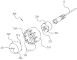
도 1은 본 발명에 따른 이중격실 사전충진 안전주사기의 일 실시예의 사시도,
도 2는 도 1의 안전주사기의 단면도,
도 3은 실린더의 내부에 분할패킹이 결합된 상태의 단면도,
도 4는 도 1의 안전주사기의 헤드유닛을 도시한 발췌사시도,
도 5 및 도 6은 도 4의 헤드유닛의 분리사시도,
도 7은 헤드유닛의 단면도,
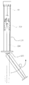
도 8은 가압차단부재를 도시한 사시도,
도 9는 헤드유닛이 실린더의 내부로 진입하고, 커넥팅로드가 절단되어 폐기 준비상태가 된 안전주사기를 도시한 도면이다. 1 is a perspective view of an embodiment of a double compartment prefilling safety syringe according to the present invention,
Figure 2 is a cross-sectional view of the safety syringe of Figure 1,
Figure 3 is a cross-sectional view of a state in which the divided packing is coupled to the interior of the cylinder,
Figure 4 is an excerpt perspective view showing the head unit of the safety syringe of Figure 1,
5 and 6 is an exploded perspective view of the head unit of Figure 4,
7 is a cross-sectional view of the head unit,
8 is a perspective view showing a pressure blocking member,
9 is a view showing a safety syringe in which the head unit enters the interior of the cylinder and the connecting rod is cut and ready for disposal.
이하, 첨부한 도면을 참조하여 본 발명의 실시예에 따른 이중격실 사전충진 안전주사기에 대해 상세히 설명한다. 본 발명은 다양한 변경을 가할 수 있고 여러 가지 형태를 가질 수 있는 바, 특정 실시 예들을 도면에 예시하고 본문에 상세하게 설명하고자 한다. 그러나 이는 본 발명을 특정한 개시 형태에 대해 한정하려는 것이 아니며, 본 발명의 사상 및 기술 범위에 포함되는 모든 변경, 균등물 내지 대체물을 포함하는 것으로 이해되어야 한다. 각 도면을 설명하면서 유사한 참조부호를 유사한 구성요소에 대해 사용하였다. 첨부된 도면에 있어서, 구조물들의 치수는 본 발명의 명확성을 기하기 위하여 실제보다 확대하여 도시한 것이다. Hereinafter, a double-compartment pre-filling safety syringe according to an embodiment of the present invention will be described in detail with reference to the accompanying drawings. The present invention can be applied to various changes and may have various forms, and specific embodiments will be illustrated in the drawings and described in detail in the text. However, this is not intended to limit the present invention to a specific disclosure form, and it should be understood as including all modifications, equivalents, and substitutes included in the spirit and scope of the present invention. In describing each drawing, similar reference numerals are used for similar components. In the accompanying drawings, the dimensions of the structures are shown to be enlarged than the actual for clarity of the present invention.
제1, 제2 등의 용어는 다양한 구성요소들을 설명하는데 사용될 수 있지만, 상기 구성요소들은 상기 용어들에 의해 한정되어서는 안 된다. 상기 용어들은 하나의 구성요소를 다른 구성요소로부터 구별하는 목적으로만 사용된다. 예를 들어, 본 발명의 권리 범위를 벗어나지 않으면서 제1 구성요소는 제2 구성요소로 명명될 수 있고, 유사하게 제2 구성요소도 제1 구성요소로 명명될 수 있다. Terms such as first and second may be used to describe various components, but the components should not be limited by the terms. The terms are used only for the purpose of distinguishing one component from other components. For example, the first component may be referred to as a second component without departing from the scope of the present invention, and similarly, the second component may be referred to as a first component.
본 출원에서 사용한 용어는 단지 특정한 실시 예를 설명하기 위해 사용된 것으로, 본 발명을 한정하려는 의도가 아니다. 단수의 표현은 문맥상 명백하게 다르게 뜻하지 않는 한, 복수의 표현을 포함한다. 본 출원에서, "포함하다" 또는 "가지다" 등의 용어는 명세서 상에 기재된 특징, 숫자, 단계, 동작, 구성요소, 부분품 또는 이들을 조합한 것이 존재함을 지정하려는 것이지, 하나 또는 그 이상의 다른 특징들이나 숫자, 단계, 동작, 구성요소, 부분품 또는 이들을 조합한 것들의 존재 또는 부가 가능성을 미리 배제하지 않는 것으로 이해되어야 한다.Terms used in the present application are only used to describe specific embodiments, and are not intended to limit the present invention. Singular expressions include plural expressions unless the context clearly indicates otherwise. In this application, terms such as “include” or “have” are intended to indicate the presence of features, numbers, steps, actions, elements, parts or combinations thereof described in the specification, but one or more other features. It should be understood that the presence or addition possibilities of fields or numbers, steps, actions, components, parts or combinations thereof are not excluded in advance.
다르게 정의되지 않는 한, 기술적이거나 과학적인 용어를 포함해서 여기서 사용되는 모든 용어들은 본 발명이 속하는 기술 분야에서 통상의 지식을 가진 자에 의해 일반적으로 이해되는 것과 동일한 의미를 가지고 있다. 일반적으로 사용되는 사전에 정의되어 있는 것과 같은 용어들은 관련 기술의 문맥 상 가지는 의미와 일치하는 의미를 가지는 것으로 해석되어야 하며, 본 출원에서 명백하게 정의하지 않는 한, 이상적이거나 과도하게 형식적인 의미로 해석되지 않는다.Unless otherwise defined, all terms used herein, including technical or scientific terms, have the same meaning as commonly understood by a person skilled in the art to which the present invention pertains. Terms such as those defined in a commonly used dictionary should be interpreted as having meanings consistent with meanings in the context of related technologies, and should not be interpreted as ideal or excessively formal meanings unless explicitly defined in the present application. Does not.
도면을 참조하면, 본 발명에 따른 이중격실 사전충진 안전주사기(이하 '안전주사기'라 함)는 주사제를 환자에게 주사한 후 주사바늘(10)이 실린더(100)의 내부로 인입되도록 함으로써 사용 후 취급 과정에서 취급자가 주사바늘(10)에 찔리는 것을 방지할 수 있는 것이다. Referring to the drawings, a double-compartment pre-filled safety syringe according to the present invention (hereinafter referred to as a'safety syringe') is used by injecting an injection agent into a patient and then injecting the
이를 위해 본원 발명의 안전주사기(1)는 실린더(100)와, 실린더(100)의 내부에 충진된 주사제를 토출하도록 가압하기 위한 가압부(200)와, 실린더(100)의 선단부에 마련되어 주사바늘(10)을 지지하는 헤드유닛(300)을 포함한다.To this end, the safety syringe 1 of the present invention is provided with a
상기 실린더(100)는 주사제가 주입될 수 있는 소정의 내부공간을 가지며, 선단부에는 주사제가 토출될 수 있는 토출홀(110)이 형성되어 있고, 후단부에는 가압부(200)의 가압패킹(210) 및 연장로드(230)가 진입 및 인출될 수 있는 진입홀(120)이 형성되어 있다. 그리고 실린더(100)의 후단부에는 주사 과정에서 사용자가 손으로 지지할 수 있는 확장지지부(130)가 형성되어 있다. The
통상적인 주사기의 경우 실린더(100)의 선단부가 전방으로 연장될수록 점점 좁아지도록 경사져 있으며, 주사바늘(10)이 바로 끼워질 수 있도록 소정직경의 원통형 돌기가 마련되지만 본 발명의 경우 후술하는 헤드유닛(300)이 실린더(100)의 선단부에 바로 체결될 수 있도록 실린더(100)는 선단부의 외경과 내경이 협소해지지 않는다. In the case of a conventional syringe, the tip portion of the
아울러 실린더(100)의 선단부 외주면에는 외측으로 소정길이 돌출되는 걸림턱(140)이 형성되어 있는데, 이 걸림턱(140)은 후술하는 헤드유닛(300)의 외부체결부재(310)가 체결될 수 있도록 형성된 것이다. In addition, a
본 실시예의 경우 두 가지 주사제를 미리 충진해 둘 수 있는 이중 챔버형 프리필드 주사기로서, 실린더(100)의 내부에 분할패킹(150)이 더 구비된다. In the case of the present embodiment, a double-chamber type pre-filled syringe capable of pre-filling two injection agents, and a divided packing 150 is further provided inside the
상기 분할패킹(150)은 실린더(100)의 내부 공간을 전방부공간과 후방부공간으로 분할하는데, 후방부공간에는 실린더(100)의 내측으로 돌출된 내부돌출구간(163)이 형성되어 있어서 후방부공간의 내경이 전방부공간의 내경보다 상대적으로 작게 형성되어 있다. The divided packing 150 divides the inner space of the
그리고 분할패킹(150)은 신축변형이 가능한 재질로 형성되며, 상기 실린더(100)의 내부에 설치될 수 있게 원통형의 모양을 갖는데, 중앙에는 전후방향으로 연통되는 소정 직경의 연통홀(151)이 형성되어 있다. And the split packing 150 is formed of a material that can be elastically deformed, and has a cylindrical shape to be installed inside the
상기 분할패킹(150)은 후방부공간에 위치할 때에는 후방부공간의 내경이 작기 때문에 압착되어 상기 연통홀(151)이 막힌 상태가 되며, 전방부공간으로 이동하면 전방부공간의 내경이 후방부공간의 내경에 비해 확장되므로 상기 연통홀(151)이 개방될 수 있는 구조를 갖는다. When the partition packing 150 is located in the rear subspace, the inner diameter of the rear subspace is small, so that the
상기 가압부(200)는 실린더(100)의 내부에서 주사제를 실린더(100)의 선단측 토출홀(110)로 가압하기 위한 것으로 실린더(100)의 내부공간에 대응하는 가압패킹(210)과, 상기 가압패킹(210)으로부터 실린더(100)의 후방을 통해 외부로 연장되는 연장로드(230)를 포함한다. The
상기 연장로드(230)의 단부를 사용자가 누르면 상기 가압패킹(210)이 실린더(100)의 내부에서 실린더(100)의 선단부 측으로 이동하면서 내부에 충진된 주사제를 상기 실린더(100)의 선단부에 형성된 토출홀(110) 측으로 가압해 토출시키도록 형성된다. When the user presses the end of the
상기 연장로드(230)는 후술하는 헤드유닛(300)과 결합되어 주사바늘(10)과 함께 헤드유닛(300)의 일부가 상기 실린더(100)의 내부로 진입하도록 이동시킨 상태에서 상기 실린더(100)의 후단부 위치에서 절단할 수 있도록 절단가이드부(231)가 형성되어 있다. The
본 실시예의 경우 상기 분할패킹(150)이 후방부공간의 선단에 위치한 상태에서 전방부공간에는 고형의 주사제를 충진하고, 후방부공간에는 액상의 주사제를 충진해 둘 수 있다. In the case of the present embodiment, in the state where the divided packing 150 is located at the front end of the rear subspace, a solid injection may be filled in the anterior space and a liquid injection may be filled in the rear subspace.
사용자가 가압패킹(210)을 전방으로 가압하면 분할패킹(150)이 전방으로 이동하면서 전방공간부(161)로 진입하게 되며, 이 때 분할패킹(150)의 연통홀(151)이 개방된다.When the user presses the pressure packing 210 forward, the split packing 150 moves forward and enters the
연통홀(151)이 개방되면 분할패킹(150)의 후방부에 충진된 액상의 주사제가 연통홀(151)을 통해 전방공간부(161)로 이동하면서 전방공간부(161)에 충진되어 있던 고형의 주사제와 혼합된다. 이때, 상기 전방공간부(161)에는 고형의 주사제들 사이에 공간이 형성되어 있기 때문에 액상의 주사제만 전방공간부(161)로 이동하며 혼합이 이루어지고, 분할패킹(150)은 정지된 상태이며 전방공간부(161)의 주사제도 외부로 토출되지 않는다.When the
상기 전방공간부(161)의 빈공간에 액상주사제가 모두 충진된 후에는 고형의 주사제와 혼합된 상태의 주사제가 가압부(200)의 가압에 따라 토출홀(110)을 통과한 다음 주사바늘(10)을 통해 환자의 체내로 주입이 이루어진다. 이 과정에서 가압부(200)의 가압에 의해 후방공간부(162)의 액상 주사제는 분할패킹(150)의 연통홀(151)을 통해 전방공간부(161)로 지속적으로 공급이 이루어지며, 가압패킹(210)이 분할패킹(150)과 접촉하게 되면 가압패킹(210)이 분할패킹(150)을 전방으로 가압하면서 전방공간부(161)에 남아있는 주사제를 토출홀(110)을 통해 외부로 토출시키게 된다. After all of the liquid injection agent is filled in the empty space of the
상기 헤드유닛(300)은 실린더(100)의 전방에 설치되어 주사바늘(10)을 지지하는 것으로서, 외부체결부재(310)와, 상기 실린더(100)의 내부에 삽입되는 제1 인출부재(320) 및 제2 인출부재(330)를 포함한다.The
외부체결부재(310)는 실린더(100)의 선단부 외경에 대응하는 내경의 중공을 갖는 원통형으로 형성되며, 후단부에는 상기 실린더(100)의 외부에 형성된 걸림턱(140)에 걸려 결합될 수 있는 턱고정부재(311)가 형성되어 있다. 상기 턱고정부재(311)는 콜릿 형상으로 형성되며 소정각도 탄성 변형이 가능하도록 형성되어 실린더(100)의 선단으로부터 후방부를 향해 끼워질 때 외측으로 벌어져 있다가 걸림턱(140)에 도달하면 실린더(100)의 내측으로 복원되면서 상기 걸림턱(140)에 걸리게 된다.The
상기 외부체결부재(310)의 선단부는 실린더(100)의 내경보다 작은 직경의 관통홀(312)이 형성되어 있는데, 이 관통홀(312)을 통해서 제2 인출부재(330)가 실린더(100)의 전방으로 인출되거나 실린더(100)의 내부로 진입할 수 있다. The front end portion of the
아울러 상기 외부체결부재(310)에는 후술하는 제2 인출부재(330)의 인입차단부(333)가 통과할 수 있도록 된 통과허용홈(313)이 형성되어 있다. 상기 통과허용홈(313)은 관통홀(312)의 일측에 형성되어 인입차단부(333)가 통과허용홈(313)에 대응하는 위치에서는 외부체결부재(310)를 통과할 수 있다. 상기 통과허용홈(313)을 제외한 나머지 구간은 상기 인입차단부(333)의 이동이 차단된다. In addition, the
상기 통과허용홈(313)과 대향되는 위치에는 제2 인출부재(330)가 실린더(100)의 내부로 진입하는 것을 차단하기 위한 진입차단부(314)가 형성되는데, 상기 통과허용홈(313)의 양측 가장자리와 진입차단부(314)의 양측 가장자리에는 각각 이탈방지돌기(315)가 마련되어 있다. 상기 이탈방지돌기(315)는 통과허용홈(313) 또는 진입차단부(314)로부터 멀어지는 방향으로 연장될수록 돌촐높이가 점점 낮아지도록 경사지게 형성되어 있는데, 제2 인출부재(330)의 인입차단부(333)가 통과허용홈(313) 똔느 진입차단부(314)에 위치해 있을 때, 의도하지 않은 외력에 의해 상기 인입차단부(333)가 해당 위치를 벗어나는 것을 방지하기 위한 것이며, 사용자가 직접 제2 인출부재(330)를 잡고 돌리면 인입차단부(333)가 이탈방지돌기(315)를 넘어가 회전할 수 있도록 된다. An
상기 제1 인출부재(320)는 실린더(100)의 선단부 내측에 위치하며 상기 제2 인출부재(330)와 연결되는 것으로, 외경이 실린더(100)의 선단부 내경에 대응하는 원통형으로 형성되어 있으며, 제1 인출부재(320)의 전면에는 복수개의 회전방지돌기(321)들이 원주방향을 따라 소정간격 이격되도록 돌출 형성되어 있다. The
상기 회전방지돌기(321)는 외부체결부재(310)의 내측면에 형성되어 있는 차단홈(316)에 끼워져 제2 인출부재(330)가 회전할 때 제2 인출부재(330)와 함께 회전하는 것이 차단될 수 있는 구조를 갖는다. The
상기 제1 인출부재(320)의 전면부에는 후술하는 제2 인출부재(330)가 전방으로 분리되지 않도록 내측으로 돌출된 고정턱(322)이 형성되어 있다. 그리고 제1 인출부재(320)의 후면부에는 통과홀(323)이 형성되어 있는데, 상기 통과홀(323)은 가압패킹(210)으로부터 연장되는 인출걸이부재(220)가 관통할 수 있도록 된 것이며, 제2 인출부재(330)의 후면에 형성된 걸이홈(332)에 통과홀(323)을 관통해 연장되는 인출걸이부재(220)가 체결될 수 있도록 형성된다. A fixed
인출걸이부재(220)는 가압부(200)가실린더(100)의 선단부 측으로 전진할 때, 분할패킹(150)의 연통홀(151)과 제1 인출부재(320)의 통과홀(323)을 통과해 제2 인출부재(330)의 걸이홈(332)으로 삽입되며, 걸이홈(332)의 직경은 인출걸이부재(220)의 후단부 회경보다 작게 형성되어 있다. 다만 인출걸이부재(220)가 전단부에서 후방으로 연장될수록 직경이 점점 커지는 절두원추형으로 형성되어 있고, 전단부의 직경은 걸이홈(332)의 직경보다 작게 형성되고 제2 인출부재(330)의 후단부가 신축성이 있는 재질로 형성되기 때문에 상기 인출걸이부재(220)가 걸이홈(332)으로 진입하는 것은 가능하지만 진입한 후에는 인출걸이부재(220)의 후단부가 걸이홈(332)의 내측으로 진입한 상태에서 걸려 인출되지 않는다.
아울러 제1 인출부재(320)에는 상기 통과홀(323)과 소정간격 이격된 위치에 주사제가 유입될 수 있는 유입홀(324)이 형성되어 있고, 제1 인출부재(320)의 내부에는 상기 유입홀(324)을 통해 유입된 주사제가 이동할 수 있는 이동공간이 형성되어 있다. In addition, the
상기 제2 인출부재(330)는 후단부가 상기 제1 인출부재(320)에 삽입 설치되는데, 상기 고정턱(322)에 걸려 전방으로 분리될 수 없도록 체결되며, 선단부는 주사바늘(10)과 체결된다. The
제2 인출부재(330)의 후단부에는 주사제가 주사바늘(10)측으로 이동할 수 있도록 연통구(331)가 형성되어 있는데, 상기 연통구(331)가 원주방향을 따라 일부 구간에만 형성되어 있어서 제2 인출부재(330)의 회전 위치에 따라 상기 연통구(331)가 주사제의 유입이 가능하도록 연통되거나 주사제의 유입이 차단되도록 폐쇄된다. A
상기 제2 인출부재(330)의 전방부 외주면에는 상술한 것처럼 인입차단부(333)가 외부로 돌출되도록 형성되어 있으며, 인입차단부(333)가 외부체결부재(310)의 통과허용홈(313)에 위치하면 상기 연통구(331)는 폐쇄되고 제2 인출부재(330)는 외부체결부재(310)를 통과해 실린더(100)의 내측으로 진입할 수 있게 되며, 인입차단부(333)가 통과허용홈(313)이 아닌 나머지 구간에 위치할 때에는 인입차단부(333)가 외부체결부재(310)에 걸려 제2 인출부재(330)가 실린더(100)의 내측으로 진입하는 것이 차단된다. 특히 상기 인입차단부(333)가 진입차단부(314)에 위치하게 되면 상기 연통구(331)가 개방되어 주사제가 제2 인출부재(330)의 내부로 유입된 후 주사바늘(10)을 통해 배출될 수 있다. On the outer circumferential surface of the front portion of the
아울러 상기 실린더(100)의 후단부에는 가압부(200)가 실린더(100)의 내부로 진입하여 가압하는 것을 차단하기 위한 가압차단부재(400)가 결합될 수 있다. In addition, a
본 실시예의 안전주사기(1)는 주사제를 실린더(100)에 미리 충진시켜두는 프리필드(pre-filled) 주사기이며 충진된 주사제가 의도하지 않은 외력에 의해 실린더(100)로부터 인출되는 것을 막도록 보관 및 운송과정에서의 가압을 방지하기 위한 수단으로 상기 가압차단부재(400)를 설치한다.The safety syringe 1 of this embodiment is a pre-filled syringe that pre-fills the injection agent with the
가압차단부재(400)는 확장지지부(130)를 중심으로 상하로 이격되어 각각 실린더(100)의 외부를 감싸는 전방지지체(410)와, 실린더(100)의 후방부에 위치하는 가압부(200)의 연장로드(230)를 감싸도록 설치되는 후방지지체(420)를 포함한다.The
도시된 것처럼 연장로드(230)는 십(十)자형의 단면형상을 갖도록 형성되며 선단부 일측에 원판형의 가로막(232)이 형성되어 있다. As shown in the drawing, the
상기 가압차단부재(400)는 전방지지체(410)에 실린더(100)의 외형에 대응하는 환형 홈이 형성되어 있고, 후방지지체(420)에는 상기 연장로드(230)에 대응하는 진입홈이 형성되어 있는 상태이고, 전방지지체(410)와 후방지지체(420)가 확장지지부(130)를 사이에 두고 끼워지면 후방지지체(420)의 상단은 확장지지부(130)에 걸리고 하단은 상기 가로막(232)에 걸려 상기 가압차단부재(400)를 끼워둔 상태에서는 가압부(200)의 연장로드(230) 및 가압패킹(210)이 실린더(100)의 내부로 진입할 수 없어 주사기의 보관 및 운반 과정에서 주사액에 누출되는 것을 방지한다. The
이상에서 설명한 본 발명에 따른 안전주사기(1)의 사용방법을 설명하면 다음과 같다. The method of using the safety syringe 1 according to the present invention described above is as follows.
먼저 실린더(100)의 내부에는 분할패킹(150)에 의해 구획된 전방공간부(161)와 후방공간부(162)에 각각 고형의 주사제와 액상의 주사제가 충진된 상태이며, 실린더(100)의 전방부에는 헤드유닛(300)이 장착되어 있다. First, the inside of the
상기 제2 인출부재(330)의 인입차단부(333)가 진입차단부(314)에 위치한 상태에서 주사바늘(10)을 주사 위치에 삽입하고, 가압부(200)를 실린더(100)의 내부로 전진시킨다.The
가압부(200)의 가압에 따라 분할패킹(150)이 전방공간부(161)로 이동하면서 연통홀(151)이 개방되어 액상의 주사제는 연통홀(151)을 통해 전방으로 이동한 뒤 고형의 주사제와 혼합되며 상기 제2 인출부재(330) 및 제2 인출부재(330)를 거쳐 주사바늘(10)을 통해 주사가 이루어진다. As the divided packing 150 moves to the
가압부(200)를 지속적으로 가압하면 액상 주사제가 모두 전방공간부(161)로 토출될 때까지는 가압패킹(210)만 이동하지만 액상 주사제가 모두 전방공간부(161)로 이동한 후에는 가압패킹(210)과 분할패킹(150)이 접촉하게 되며 분할패킹(150)이 가압패킹(210)에 의해 밀려 전방으로 이동한다. 이 때, 상기 가압패킹(210)으로부터 전방으로 연장되는 인출걸이부재(220)는 분할패킹(150)의 연통홀(151)을 통과해 전방으로 돌출되어 있다. If the
가압패킹(210)과 분할패킹(150)이 점점 전진하면서 분할패킹(150)이 실린더(100)의 전방측으로 이동하고 주사제가 모두 배출되는 상태가 될 때, 상기 인출걸이부재(220)는 제2 인출부재(330)의 걸이홈(332)으로 삽입되어 걸리게 된다. When the pressure packing 210 and the split packing 150 are gradually advanced, when the split packing 150 moves to the front side of the
주사가 모두 이루어진 다음 사용자는 주사바늘(10)을 환자의 신체로부터 빼낸 다음 상기 제2 인출부재(330)의 인입차단부(333)가 통과허용홈(313)에 위치하도록 제2 인출부재(330)를 회전시킨다. 이 상태에서 연장로드(230)를 실린더(100)의 후방으로 당기면 상기 인출걸이부재(220)에 의해 걸려 있는 제2 인출부재(330)가 제1 인출부재(320)와 함께 견인되어 실린더(100)의 내부로 진입할 수 있게 된다. After all the injections are made, the user removes the
상기 주사바늘(10)의 단부가 노출되지 않도록 실린더(100)의 내부로 충분히 진입시킨 상태에서 상기 연장로드(230)의 절단가이드부(231)에서 연장로드(230)를 절단한다. The
이렇게 연장로드(230)의 절단까지 완료하면 연장로드(230)로부터 주사바늘(10)까지 모두 실린더(100)의 내부로 인입되어 노출되지 않으므로, 취급 및 폐기 과정에서 주사바늘(10)에 취급자가 찔리는 것을 방지할 수 있다. When the cutting of the
본 실시예에서는 상기 실린더(100)가 두 가지 주사제가 충진되는 프리필드 주사기로서 내부에 분할패킹(150)이 마련되어 있는 상태이지만 상기 이와는 달리 1종의 주사제가 충진된 프리필드 주사기이거나 주사제가 저장된 약병에서 주사제를 인출한 다음 주사가 이루어지는 일반적인 주사기에도 적용될 수 있다. In this embodiment, the
제시된 실시예들에 대한 설명은 임의의 본 발명의 기술분야에서 통상의 지식을 가진 자가 본 발명을 이용하거나 또는 실시할 수 있도록 제공된다. 이러한 실시예들에 대한 다양한 변형들은 본 발명의 기술 분야에서 통상의 지식을 가진자에게 명백할 것이며, 여기에 정의된 일반적인 원리들은 본 발명의 범위를 벗어남이 없이 다른 실시예들에 적용될 수 있다. 그리하여, 본 발명은 여기에 제시된 실시예들로 한정되는 것이 아니라, 여기에 제시된 원리들 및 신규한 특징들과 일관되는 최광의의 범위에서 해석되어야 할 것이다.The description of the presented embodiments is provided to enable any person of ordinary skill in the art to use or practice the present invention. Various modifications to these embodiments will be apparent to those skilled in the art of the present invention, and the general principles defined herein can be applied to other embodiments without departing from the scope of the present invention. Thus, the present invention should not be limited to the embodiments presented herein, but should be interpreted in the broadest scope consistent with the principles and novel features presented herein.
1: 안전주사기
10: 주사바늘
100: 실린더
110: 토출홀
120: 진입홀
130: 확장지지부
140: 걸림턱
150: 분할패킹
151: 연통홀
161: 전방공간부
162: 후방공간부
163: 내부돌출구간
200: 가압부
210: 가압패킹
220: 인출걸이부재
230: 연장로드
231: 절단가이드부
232: 가로막
300: 헤드유닛
310: 외부체결부재
311: 턱고정부재
312: 관통홀
313: 통과허용홈
314: 진입차단부
315: 이탈방지돌기
316: 차단홈
320: 제1 인출부재
321: 회전방지돌기
322: 고정턱
323: 통과홀
324: 유입홀
330: 제2 인출부재
331: 연통구
332: 걸이홈
333: 인입차단부
400: 가압차단부재
410: 전방지지체
420: 후방지지체1: Safety syringe
10: needle
100: cylinder
110: discharge hole 120: entrance hole
130: extended support portion 140: locking jaw
150: split packing 151: communication hole
161: front space portion 162: rear space portion
163: internal protrusion section
200: pressing part
210: pressurized packing 220: withdrawal hook member
230: extension rod 231: cutting guide
232: curtain
300: head unit
310: external fastening member 311: jaw fixing member
312: Through hole 313: Pass through groove
314: entry block 315: departure prevention projections
316: blocking groove 320: first withdrawal member
321: anti-rotation projection 322: fixed jaw
323: Passing hole 324: Inflow hole
330: second withdrawal member 331: communication port
332: hook groove 333: incoming block
400: pressure blocking member
410: front support 420: rear support
Claims (3)
상기 실린더의 내부에 삽입되어 상기 실린더의 내부에 충진된 주사제를 상기 토출홀 측으로 가압할 수 있는 가압패킹 및 상기 가압패킹으로부터 상기 실린더의 외부로 연장되는 연장로드를 포함하는 가압부와;
상기 실린더의 내부에 설치되어 상기 실린더의 내부 공간을 전방부공간과 후방부공간으로 분할하기 위한 분할패킹과
상기 토출홀을 통해 토출되는 주사제를 환자의 피부 속으로 주입하도록 삽입되는 주사바늘과;
상기 실린더의 선단부에 설치되어 상기 주사바늘을 지지하는 헤드유닛을 포함하되,
상기 헤드유닛은 상기 실린더의 외측에 고정 설치되는 외부체결부재와,
상기 실린더의 내부에 삽입되어 상기 외부체결부재에 의해 상기 실린더의 외부로 이탈하는 것은 차단되며, 주사제의 주입 후 상기 가압부와 연결되는 제1 인출부재와,
상기 제1 인출부재에 체결되며 상기 주사바늘이 연결되고, 상기 실린더의 내부로 진입을 허용하거나 차단하도록 상기 외부체결부재에 걸리거나 걸림이 해제될 수 있는 인입차단부를 포함하는 제2 인출부재를 포함하고,
상기 연장로드는 상기 주사바늘 및 헤드유닛의 제1 인출부재와 제2 인출부재가 상기 실린더의 내부로 진입하여 상기 주사바늘이 외부로 노출되지 않은 상태에 있을 때, 상기 실린더의 후단부에 대응하는 위치에서 절단할 수 있는 절단가이드부가 형성되어 있으며,
상기 분할패킹은 중앙부에 주사제가 통과할 수 있는 연통홀이 형성되어 있고, 신축변형이 가능한 재질로 형성되며,
상기 실린더의 내주면에는 후방부에 상기 분할패킹이 진입할 때, 상기 연통홀이 폐쇄될 수 있도록 상기 분할패킹이 압축 변형되도록 유도하는 내부돌출구간이 형성되어 있고, 상기 분할패킹이 내부돌출구간을 벗어나 상기 전방부공간으로 진입하면 상기 연통홀이 개방될 수 있게 형성된 이중격실 사전충진 안전주사기.
A cylinder having an inner space into which the injection agent is injected, and having a discharge hole formed so that the injection agent is discharged at a tip end;
A pressing part inserted into the cylinder and including a pressure packing capable of pressing the injection agent filled in the inside of the cylinder toward the discharge hole and an extension rod extending from the pressure packing to the outside of the cylinder;
It is installed in the interior of the cylinder and divided packing for dividing the inner space of the cylinder into a front part space and a rear part space.
An injection needle inserted to inject the injection agent discharged through the discharge hole into the patient's skin;
It is installed on the front end of the cylinder includes a head unit for supporting the injection needle,
The head unit is an external fastening member fixedly installed on the outside of the cylinder,
It is inserted into the interior of the cylinder is blocked from leaving the outside of the cylinder by the external fastening member, the first withdrawal member connected to the pressing portion after injection of the injection,
It is fastened to the first withdrawal member, the injection needle is connected, and includes a second withdrawal member including a withdrawal blocking portion that can be caught or released from the external fastening member to allow or block entry into the interior of the cylinder and,
The extension rod corresponds to the rear end of the cylinder when the first and second withdrawal members of the injection needle and the head unit enter the interior of the cylinder and the injection needle is not exposed to the outside. A cutting guide part that can be cut at the position is formed,
The divided packing is formed with a communication hole through which an injection agent can pass in the center, and is formed of a material capable of elastic deformation,
An inner protrusion section is formed on the inner circumferential surface of the cylinder so that the split packing is compressed and deformed so that the communication hole is closed when the split packing enters the rear portion, and the split packing leaves the inner protrusion section. A double-compartment pre-filled safety syringe configured to open the communication hole when entering the front space.
상기 외부체결부재는 상기 실린더의 선단부 외경에 대응하는 내경의 중공이 형성되어 있으며, 하단부는 상기 실린더의 선단부에 외부로 돌출되게 형성된 걸림턱에 걸리는 걸이부가 형성되어 있으며,
상기 제1 인출부재는 상기 실린더의 내경에 대응하는 외경의 원통부재로 하단부에는 상기 가압패킹으로부터 연장되는 인출걸이부재가 통과할 수 있는 통과홀이 형성되며, 상단부에는 상기 외부체결부재의 상면 내측에 형성된 차단홈에 삽입되어 상기 제1 인출부재가 상기 외부체결부재에 대하여 회전하는 것을 차단하기 위한 회전방지돌기가 원주방향을 따라 소정간격 이격되어 상방으로 소정길이 돌출되게 형성되어 있고,
상기 제2 인출부재에는 상기 통과홀을 통과해 진입한 인출걸이부재가 삽입 및 결합되는 걸이홈이 형성된 것을 특징으로 하는 이중격실 사전충진 안전주사기.
According to claim 1,
The outer fastening member is formed with a hollow of an inner diameter corresponding to the outer diameter of the front end of the cylinder, and a lower end is formed with a hook portion hanging from a locking jaw formed to protrude to the outside of the front end of the cylinder,
The first drawing member is a cylindrical member having an outer diameter corresponding to the inner diameter of the cylinder, and a through hole through which a drawing hook member extending from the pressurizing packing extends is formed at a lower portion, and an upper portion inside the upper surface of the external fastening member. It is inserted into the formed blocking groove, and the anti-rotation protrusion for blocking the first withdrawal member from rotating with respect to the external fastening member is spaced at a predetermined interval along the circumferential direction, and is formed to protrude upward a predetermined length,
The second withdrawal member is a double-compartment prefilling safety syringe, characterized in that a hook groove is formed through which the withdrawal hook member is inserted and coupled through the through hole.
상기 제2 인출부재에 형성된 인입차단부는 상기 제2 인출부재의 외주면으로부터 외측으로 소정길이 돌출되어 있고,
상기 외부체결부재는 상면에 상기 제2 인출부재가 실린더의 전방을 향해 돌출될 수 있도록 관통홀이 형성되되,
상기 관통홀을 중심으로 일측에는 상기 인입차단부가 통과해 외부체결부재의 내부로 이동이 허용될 수 있는 통과허용홈이 형성되어 있고, 상기 통과허용홈을 제외한 나머지 영역은 상기 인입차단부가 통과할 수 없도록 내경이 상기 제2 인출부재의 외경에 대응하도록 형성된 것을 특징으로 하는 이중격실 사전충진 안전주사기.
According to claim 2,
The inlet blocking portion formed in the second withdrawal member protrudes a predetermined length outward from the outer circumferential surface of the second withdrawal member,
The external fastening member is formed with a through hole on the upper surface so that the second drawing member protrudes toward the front of the cylinder,
A pass through groove through which the intake blocking part passes can be allowed to move into the inside of the external fastening member is formed on one side of the through hole, and the rest of the blocking part can pass through the through hole. Double compartment pre-filled safety syringe, characterized in that the inner diameter is formed so as to correspond to the outer diameter of the second drawing member.
Priority Applications (1)
| Application Number | Priority Date | Filing Date | Title |
|---|---|---|---|
| KR1020180156694A KR20200069539A (en) | 2018-12-07 | 2018-12-07 | Safety syringe |
Applications Claiming Priority (1)
| Application Number | Priority Date | Filing Date | Title |
|---|---|---|---|
| KR1020180156694A KR20200069539A (en) | 2018-12-07 | 2018-12-07 | Safety syringe |
Publications (1)
| Publication Number | Publication Date |
|---|---|
| KR20200069539A true KR20200069539A (en) | 2020-06-17 |
Family
ID=71405578
Family Applications (1)
| Application Number | Title | Priority Date | Filing Date |
|---|---|---|---|
| KR1020180156694A KR20200069539A (en) | 2018-12-07 | 2018-12-07 | Safety syringe |
Country Status (1)
| Country | Link |
|---|---|
| KR (1) | KR20200069539A (en) |
Cited By (3)
| Publication number | Priority date | Publication date | Assignee | Title |
|---|---|---|---|---|
| KR20220142669A (en) * | 2021-04-15 | 2022-10-24 | 주식회사 용창 | Disposable Syringe with Separated Head |
| KR20230021524A (en) * | 2021-08-05 | 2023-02-14 | 장영환 | A powder and liquid medicine, Needle Embedded Manual Syringe Assembly |
| KR20230021530A (en) * | 2021-08-05 | 2023-02-14 | 장영환 | A powder and liquid medicine, Needle Embedded Auto Syringe Apparatus |
Citations (2)
| Publication number | Priority date | Publication date | Assignee | Title |
|---|---|---|---|---|
| KR20160144117A (en) | 2015-06-08 | 2016-12-16 | 김종윤 | Safety syringe |
| KR101763425B1 (en) | 2009-05-05 | 2017-08-03 | 사크하람 디. 마허커 | Universal safety syringe |
-
2018
- 2018-12-07 KR KR1020180156694A patent/KR20200069539A/en not_active Application Discontinuation
Patent Citations (2)
| Publication number | Priority date | Publication date | Assignee | Title |
|---|---|---|---|---|
| KR101763425B1 (en) | 2009-05-05 | 2017-08-03 | 사크하람 디. 마허커 | Universal safety syringe |
| KR20160144117A (en) | 2015-06-08 | 2016-12-16 | 김종윤 | Safety syringe |
Cited By (3)
| Publication number | Priority date | Publication date | Assignee | Title |
|---|---|---|---|---|
| KR20220142669A (en) * | 2021-04-15 | 2022-10-24 | 주식회사 용창 | Disposable Syringe with Separated Head |
| KR20230021524A (en) * | 2021-08-05 | 2023-02-14 | 장영환 | A powder and liquid medicine, Needle Embedded Manual Syringe Assembly |
| KR20230021530A (en) * | 2021-08-05 | 2023-02-14 | 장영환 | A powder and liquid medicine, Needle Embedded Auto Syringe Apparatus |
Similar Documents
| Publication | Publication Date | Title |
|---|---|---|
| JP7345895B2 (en) | Systems and methods for safety syringes | |
| ES2701166T3 (en) | Double chamber syringe with passive retraction needle | |
| FI106536B (en) | Injection syringe | |
| JP3054444B2 (en) | Needle retraction mechanism | |
| EP0324009B1 (en) | Hazardous material vial apparatus and method | |
| US9295788B2 (en) | Syringe with integrated cannula | |
| ES2230201T3 (en) | HYPODERMIC SYRINGE WITH SELECTIVELY RETRACTABLE NEEDLE. | |
| US6221052B1 (en) | Retracting needle syringe | |
| US20090299285A1 (en) | Extendable auto retractable medical syringe | |
| KR20200069539A (en) | Safety syringe | |
| US6277102B1 (en) | Hypodermic syringe system and method of manufacture | |
| JP2004504889A (en) | Retractable needle medical device that injects liquid from a pre-filled cartridge | |
| SK105094A3 (en) | Applicating ampule set with needle, having retractable needle | |
| JP2005508656A (en) | Prefilled safe vial injector | |
| US20070066936A1 (en) | Automatic retractable safety syringe | |
| NO20110087A1 (en) | Reusable auto injector with filler | |
| EA028839B1 (en) | Injection device, method for introducing fluid medium in injection device and set for injections | |
| JP2006297126A (en) | Safe injection device for liquid or semi-solid composition | |
| KR20190128609A (en) | Insulin safety syringe | |
| KR101532413B1 (en) | Disposable syringe having safety filter function | |
| KR102603583B1 (en) | mixing vial | |
| KR20200017449A (en) | Non-reusable disposable safety syringe | |
| TW201026351A (en) | Injector and two-chamber system with sterile components | |
| BR112020018331A2 (en) | DEVICES FOR INJECTION OF MEDICINES AND METHODS OF USE | |
| KR20190044897A (en) | Safety syringe |
Legal Events
| Date | Code | Title | Description |
|---|---|---|---|
| E902 | Notification of reason for refusal | ||
| E601 | Decision to refuse application |