KR20200067188A - How to check the function of braking system and braking system - Google Patents
How to check the function of braking system and braking system Download PDFInfo
- Publication number
- KR20200067188A KR20200067188A KR1020207013759A KR20207013759A KR20200067188A KR 20200067188 A KR20200067188 A KR 20200067188A KR 1020207013759 A KR1020207013759 A KR 1020207013759A KR 20207013759 A KR20207013759 A KR 20207013759A KR 20200067188 A KR20200067188 A KR 20200067188A
- Authority
- KR
- South Korea
- Prior art keywords
- pressure
- braking system
- brake
- wheel
- sys
- Prior art date
Links
Images

Classifications
-
- B—PERFORMING OPERATIONS; TRANSPORTING
- B60—VEHICLES IN GENERAL
- B60T—VEHICLE BRAKE CONTROL SYSTEMS OR PARTS THEREOF; BRAKE CONTROL SYSTEMS OR PARTS THEREOF, IN GENERAL; ARRANGEMENT OF BRAKING ELEMENTS ON VEHICLES IN GENERAL; PORTABLE DEVICES FOR PREVENTING UNWANTED MOVEMENT OF VEHICLES; VEHICLE MODIFICATIONS TO FACILITATE COOLING OF BRAKES
- B60T17/00—Component parts, details, or accessories of power brake systems not covered by groups B60T8/00, B60T13/00 or B60T15/00, or presenting other characteristic features
- B60T17/18—Safety devices; Monitoring
- B60T17/22—Devices for monitoring or checking brake systems; Signal devices
- B60T17/221—Procedure or apparatus for checking or keeping in a correct functioning condition of brake systems
-
- B—PERFORMING OPERATIONS; TRANSPORTING
- B60—VEHICLES IN GENERAL
- B60T—VEHICLE BRAKE CONTROL SYSTEMS OR PARTS THEREOF; BRAKE CONTROL SYSTEMS OR PARTS THEREOF, IN GENERAL; ARRANGEMENT OF BRAKING ELEMENTS ON VEHICLES IN GENERAL; PORTABLE DEVICES FOR PREVENTING UNWANTED MOVEMENT OF VEHICLES; VEHICLE MODIFICATIONS TO FACILITATE COOLING OF BRAKES
- B60T13/00—Transmitting braking action from initiating means to ultimate brake actuator with power assistance or drive; Brake systems incorporating such transmitting means, e.g. air-pressure brake systems
- B60T13/10—Transmitting braking action from initiating means to ultimate brake actuator with power assistance or drive; Brake systems incorporating such transmitting means, e.g. air-pressure brake systems with fluid assistance, drive, or release
- B60T13/12—Transmitting braking action from initiating means to ultimate brake actuator with power assistance or drive; Brake systems incorporating such transmitting means, e.g. air-pressure brake systems with fluid assistance, drive, or release the fluid being liquid
- B60T13/14—Transmitting braking action from initiating means to ultimate brake actuator with power assistance or drive; Brake systems incorporating such transmitting means, e.g. air-pressure brake systems with fluid assistance, drive, or release the fluid being liquid using accumulators or reservoirs fed by pumps
- B60T13/142—Systems with master cylinder
- B60T13/145—Master cylinder integrated or hydraulically coupled with booster
- B60T13/146—Part of the system directly actuated by booster pressure
-
- B—PERFORMING OPERATIONS; TRANSPORTING
- B60—VEHICLES IN GENERAL
- B60T—VEHICLE BRAKE CONTROL SYSTEMS OR PARTS THEREOF; BRAKE CONTROL SYSTEMS OR PARTS THEREOF, IN GENERAL; ARRANGEMENT OF BRAKING ELEMENTS ON VEHICLES IN GENERAL; PORTABLE DEVICES FOR PREVENTING UNWANTED MOVEMENT OF VEHICLES; VEHICLE MODIFICATIONS TO FACILITATE COOLING OF BRAKES
- B60T13/00—Transmitting braking action from initiating means to ultimate brake actuator with power assistance or drive; Brake systems incorporating such transmitting means, e.g. air-pressure brake systems
- B60T13/10—Transmitting braking action from initiating means to ultimate brake actuator with power assistance or drive; Brake systems incorporating such transmitting means, e.g. air-pressure brake systems with fluid assistance, drive, or release
- B60T13/12—Transmitting braking action from initiating means to ultimate brake actuator with power assistance or drive; Brake systems incorporating such transmitting means, e.g. air-pressure brake systems with fluid assistance, drive, or release the fluid being liquid
- B60T13/16—Transmitting braking action from initiating means to ultimate brake actuator with power assistance or drive; Brake systems incorporating such transmitting means, e.g. air-pressure brake systems with fluid assistance, drive, or release the fluid being liquid using pumps directly, i.e. without interposition of accumulators or reservoirs
- B60T13/161—Systems with master cylinder
- B60T13/165—Master cylinder integrated or hydraulically coupled with booster
- B60T13/166—Part of the system directly actuated by booster pressure
-
- B—PERFORMING OPERATIONS; TRANSPORTING
- B60—VEHICLES IN GENERAL
- B60T—VEHICLE BRAKE CONTROL SYSTEMS OR PARTS THEREOF; BRAKE CONTROL SYSTEMS OR PARTS THEREOF, IN GENERAL; ARRANGEMENT OF BRAKING ELEMENTS ON VEHICLES IN GENERAL; PORTABLE DEVICES FOR PREVENTING UNWANTED MOVEMENT OF VEHICLES; VEHICLE MODIFICATIONS TO FACILITATE COOLING OF BRAKES
- B60T13/00—Transmitting braking action from initiating means to ultimate brake actuator with power assistance or drive; Brake systems incorporating such transmitting means, e.g. air-pressure brake systems
- B60T13/10—Transmitting braking action from initiating means to ultimate brake actuator with power assistance or drive; Brake systems incorporating such transmitting means, e.g. air-pressure brake systems with fluid assistance, drive, or release
- B60T13/58—Combined or convertible systems
-
- B—PERFORMING OPERATIONS; TRANSPORTING
- B60—VEHICLES IN GENERAL
- B60T—VEHICLE BRAKE CONTROL SYSTEMS OR PARTS THEREOF; BRAKE CONTROL SYSTEMS OR PARTS THEREOF, IN GENERAL; ARRANGEMENT OF BRAKING ELEMENTS ON VEHICLES IN GENERAL; PORTABLE DEVICES FOR PREVENTING UNWANTED MOVEMENT OF VEHICLES; VEHICLE MODIFICATIONS TO FACILITATE COOLING OF BRAKES
- B60T13/00—Transmitting braking action from initiating means to ultimate brake actuator with power assistance or drive; Brake systems incorporating such transmitting means, e.g. air-pressure brake systems
- B60T13/10—Transmitting braking action from initiating means to ultimate brake actuator with power assistance or drive; Brake systems incorporating such transmitting means, e.g. air-pressure brake systems with fluid assistance, drive, or release
- B60T13/66—Electrical control in fluid-pressure brake systems
- B60T13/662—Electrical control in fluid-pressure brake systems characterised by specified functions of the control system components
-
- B—PERFORMING OPERATIONS; TRANSPORTING
- B60—VEHICLES IN GENERAL
- B60T—VEHICLE BRAKE CONTROL SYSTEMS OR PARTS THEREOF; BRAKE CONTROL SYSTEMS OR PARTS THEREOF, IN GENERAL; ARRANGEMENT OF BRAKING ELEMENTS ON VEHICLES IN GENERAL; PORTABLE DEVICES FOR PREVENTING UNWANTED MOVEMENT OF VEHICLES; VEHICLE MODIFICATIONS TO FACILITATE COOLING OF BRAKES
- B60T13/00—Transmitting braking action from initiating means to ultimate brake actuator with power assistance or drive; Brake systems incorporating such transmitting means, e.g. air-pressure brake systems
- B60T13/10—Transmitting braking action from initiating means to ultimate brake actuator with power assistance or drive; Brake systems incorporating such transmitting means, e.g. air-pressure brake systems with fluid assistance, drive, or release
- B60T13/66—Electrical control in fluid-pressure brake systems
- B60T13/68—Electrical control in fluid-pressure brake systems by electrically-controlled valves
- B60T13/686—Electrical control in fluid-pressure brake systems by electrically-controlled valves in hydraulic systems or parts thereof
-
- B—PERFORMING OPERATIONS; TRANSPORTING
- B60—VEHICLES IN GENERAL
- B60T—VEHICLE BRAKE CONTROL SYSTEMS OR PARTS THEREOF; BRAKE CONTROL SYSTEMS OR PARTS THEREOF, IN GENERAL; ARRANGEMENT OF BRAKING ELEMENTS ON VEHICLES IN GENERAL; PORTABLE DEVICES FOR PREVENTING UNWANTED MOVEMENT OF VEHICLES; VEHICLE MODIFICATIONS TO FACILITATE COOLING OF BRAKES
- B60T13/00—Transmitting braking action from initiating means to ultimate brake actuator with power assistance or drive; Brake systems incorporating such transmitting means, e.g. air-pressure brake systems
- B60T13/74—Transmitting braking action from initiating means to ultimate brake actuator with power assistance or drive; Brake systems incorporating such transmitting means, e.g. air-pressure brake systems with electrical assistance or drive
- B60T13/741—Transmitting braking action from initiating means to ultimate brake actuator with power assistance or drive; Brake systems incorporating such transmitting means, e.g. air-pressure brake systems with electrical assistance or drive acting on an ultimate actuator
-
- B—PERFORMING OPERATIONS; TRANSPORTING
- B60—VEHICLES IN GENERAL
- B60T—VEHICLE BRAKE CONTROL SYSTEMS OR PARTS THEREOF; BRAKE CONTROL SYSTEMS OR PARTS THEREOF, IN GENERAL; ARRANGEMENT OF BRAKING ELEMENTS ON VEHICLES IN GENERAL; PORTABLE DEVICES FOR PREVENTING UNWANTED MOVEMENT OF VEHICLES; VEHICLE MODIFICATIONS TO FACILITATE COOLING OF BRAKES
- B60T13/00—Transmitting braking action from initiating means to ultimate brake actuator with power assistance or drive; Brake systems incorporating such transmitting means, e.g. air-pressure brake systems
- B60T13/74—Transmitting braking action from initiating means to ultimate brake actuator with power assistance or drive; Brake systems incorporating such transmitting means, e.g. air-pressure brake systems with electrical assistance or drive
- B60T13/745—Transmitting braking action from initiating means to ultimate brake actuator with power assistance or drive; Brake systems incorporating such transmitting means, e.g. air-pressure brake systems with electrical assistance or drive acting on a hydraulic system, e.g. a master cylinder
-
- B—PERFORMING OPERATIONS; TRANSPORTING
- B60—VEHICLES IN GENERAL
- B60T—VEHICLE BRAKE CONTROL SYSTEMS OR PARTS THEREOF; BRAKE CONTROL SYSTEMS OR PARTS THEREOF, IN GENERAL; ARRANGEMENT OF BRAKING ELEMENTS ON VEHICLES IN GENERAL; PORTABLE DEVICES FOR PREVENTING UNWANTED MOVEMENT OF VEHICLES; VEHICLE MODIFICATIONS TO FACILITATE COOLING OF BRAKES
- B60T17/00—Component parts, details, or accessories of power brake systems not covered by groups B60T8/00, B60T13/00 or B60T15/00, or presenting other characteristic features
- B60T17/18—Safety devices; Monitoring
- B60T17/22—Devices for monitoring or checking brake systems; Signal devices
- B60T17/221—Procedure or apparatus for checking or keeping in a correct functioning condition of brake systems
- B60T17/222—Procedure or apparatus for checking or keeping in a correct functioning condition of brake systems by filling or bleeding of hydraulic systems
-
- B—PERFORMING OPERATIONS; TRANSPORTING
- B60—VEHICLES IN GENERAL
- B60T—VEHICLE BRAKE CONTROL SYSTEMS OR PARTS THEREOF; BRAKE CONTROL SYSTEMS OR PARTS THEREOF, IN GENERAL; ARRANGEMENT OF BRAKING ELEMENTS ON VEHICLES IN GENERAL; PORTABLE DEVICES FOR PREVENTING UNWANTED MOVEMENT OF VEHICLES; VEHICLE MODIFICATIONS TO FACILITATE COOLING OF BRAKES
- B60T8/00—Arrangements for adjusting wheel-braking force to meet varying vehicular or ground-surface conditions, e.g. limiting or varying distribution of braking force
- B60T8/32—Arrangements for adjusting wheel-braking force to meet varying vehicular or ground-surface conditions, e.g. limiting or varying distribution of braking force responsive to a speed condition, e.g. acceleration or deceleration
- B60T8/88—Arrangements for adjusting wheel-braking force to meet varying vehicular or ground-surface conditions, e.g. limiting or varying distribution of braking force responsive to a speed condition, e.g. acceleration or deceleration with failure responsive means, i.e. means for detecting and indicating faulty operation of the speed responsive control means
- B60T8/885—Arrangements for adjusting wheel-braking force to meet varying vehicular or ground-surface conditions, e.g. limiting or varying distribution of braking force responsive to a speed condition, e.g. acceleration or deceleration with failure responsive means, i.e. means for detecting and indicating faulty operation of the speed responsive control means using electrical circuitry
-
- B—PERFORMING OPERATIONS; TRANSPORTING
- B60—VEHICLES IN GENERAL
- B60T—VEHICLE BRAKE CONTROL SYSTEMS OR PARTS THEREOF; BRAKE CONTROL SYSTEMS OR PARTS THEREOF, IN GENERAL; ARRANGEMENT OF BRAKING ELEMENTS ON VEHICLES IN GENERAL; PORTABLE DEVICES FOR PREVENTING UNWANTED MOVEMENT OF VEHICLES; VEHICLE MODIFICATIONS TO FACILITATE COOLING OF BRAKES
- B60T8/00—Arrangements for adjusting wheel-braking force to meet varying vehicular or ground-surface conditions, e.g. limiting or varying distribution of braking force
- B60T8/32—Arrangements for adjusting wheel-braking force to meet varying vehicular or ground-surface conditions, e.g. limiting or varying distribution of braking force responsive to a speed condition, e.g. acceleration or deceleration
- B60T8/88—Arrangements for adjusting wheel-braking force to meet varying vehicular or ground-surface conditions, e.g. limiting or varying distribution of braking force responsive to a speed condition, e.g. acceleration or deceleration with failure responsive means, i.e. means for detecting and indicating faulty operation of the speed responsive control means
- B60T8/90—Arrangements for adjusting wheel-braking force to meet varying vehicular or ground-surface conditions, e.g. limiting or varying distribution of braking force responsive to a speed condition, e.g. acceleration or deceleration with failure responsive means, i.e. means for detecting and indicating faulty operation of the speed responsive control means using a simulated speed signal to test speed responsive control means
-
- B—PERFORMING OPERATIONS; TRANSPORTING
- B60—VEHICLES IN GENERAL
- B60T—VEHICLE BRAKE CONTROL SYSTEMS OR PARTS THEREOF; BRAKE CONTROL SYSTEMS OR PARTS THEREOF, IN GENERAL; ARRANGEMENT OF BRAKING ELEMENTS ON VEHICLES IN GENERAL; PORTABLE DEVICES FOR PREVENTING UNWANTED MOVEMENT OF VEHICLES; VEHICLE MODIFICATIONS TO FACILITATE COOLING OF BRAKES
- B60T13/00—Transmitting braking action from initiating means to ultimate brake actuator with power assistance or drive; Brake systems incorporating such transmitting means, e.g. air-pressure brake systems
- B60T13/10—Transmitting braking action from initiating means to ultimate brake actuator with power assistance or drive; Brake systems incorporating such transmitting means, e.g. air-pressure brake systems with fluid assistance, drive, or release
- B60T13/12—Transmitting braking action from initiating means to ultimate brake actuator with power assistance or drive; Brake systems incorporating such transmitting means, e.g. air-pressure brake systems with fluid assistance, drive, or release the fluid being liquid
- B60T13/14—Transmitting braking action from initiating means to ultimate brake actuator with power assistance or drive; Brake systems incorporating such transmitting means, e.g. air-pressure brake systems with fluid assistance, drive, or release the fluid being liquid using accumulators or reservoirs fed by pumps
- B60T13/142—Systems with master cylinder
- B60T13/145—Master cylinder integrated or hydraulically coupled with booster
-
- B—PERFORMING OPERATIONS; TRANSPORTING
- B60—VEHICLES IN GENERAL
- B60T—VEHICLE BRAKE CONTROL SYSTEMS OR PARTS THEREOF; BRAKE CONTROL SYSTEMS OR PARTS THEREOF, IN GENERAL; ARRANGEMENT OF BRAKING ELEMENTS ON VEHICLES IN GENERAL; PORTABLE DEVICES FOR PREVENTING UNWANTED MOVEMENT OF VEHICLES; VEHICLE MODIFICATIONS TO FACILITATE COOLING OF BRAKES
- B60T13/00—Transmitting braking action from initiating means to ultimate brake actuator with power assistance or drive; Brake systems incorporating such transmitting means, e.g. air-pressure brake systems
- B60T13/10—Transmitting braking action from initiating means to ultimate brake actuator with power assistance or drive; Brake systems incorporating such transmitting means, e.g. air-pressure brake systems with fluid assistance, drive, or release
- B60T13/12—Transmitting braking action from initiating means to ultimate brake actuator with power assistance or drive; Brake systems incorporating such transmitting means, e.g. air-pressure brake systems with fluid assistance, drive, or release the fluid being liquid
- B60T13/16—Transmitting braking action from initiating means to ultimate brake actuator with power assistance or drive; Brake systems incorporating such transmitting means, e.g. air-pressure brake systems with fluid assistance, drive, or release the fluid being liquid using pumps directly, i.e. without interposition of accumulators or reservoirs
- B60T13/161—Systems with master cylinder
- B60T13/165—Master cylinder integrated or hydraulically coupled with booster
-
- B—PERFORMING OPERATIONS; TRANSPORTING
- B60—VEHICLES IN GENERAL
- B60T—VEHICLE BRAKE CONTROL SYSTEMS OR PARTS THEREOF; BRAKE CONTROL SYSTEMS OR PARTS THEREOF, IN GENERAL; ARRANGEMENT OF BRAKING ELEMENTS ON VEHICLES IN GENERAL; PORTABLE DEVICES FOR PREVENTING UNWANTED MOVEMENT OF VEHICLES; VEHICLE MODIFICATIONS TO FACILITATE COOLING OF BRAKES
- B60T2220/00—Monitoring, detecting driver behaviour; Signalling thereof; Counteracting thereof
- B60T2220/04—Pedal travel sensor, stroke sensor; Sensing brake request
-
- B—PERFORMING OPERATIONS; TRANSPORTING
- B60—VEHICLES IN GENERAL
- B60T—VEHICLE BRAKE CONTROL SYSTEMS OR PARTS THEREOF; BRAKE CONTROL SYSTEMS OR PARTS THEREOF, IN GENERAL; ARRANGEMENT OF BRAKING ELEMENTS ON VEHICLES IN GENERAL; PORTABLE DEVICES FOR PREVENTING UNWANTED MOVEMENT OF VEHICLES; VEHICLE MODIFICATIONS TO FACILITATE COOLING OF BRAKES
- B60T2270/00—Further aspects of brake control systems not otherwise provided for
- B60T2270/40—Failsafe aspects of brake control systems
- B60T2270/402—Back-up
-
- B—PERFORMING OPERATIONS; TRANSPORTING
- B60—VEHICLES IN GENERAL
- B60T—VEHICLE BRAKE CONTROL SYSTEMS OR PARTS THEREOF; BRAKE CONTROL SYSTEMS OR PARTS THEREOF, IN GENERAL; ARRANGEMENT OF BRAKING ELEMENTS ON VEHICLES IN GENERAL; PORTABLE DEVICES FOR PREVENTING UNWANTED MOVEMENT OF VEHICLES; VEHICLE MODIFICATIONS TO FACILITATE COOLING OF BRAKES
- B60T2270/00—Further aspects of brake control systems not otherwise provided for
- B60T2270/40—Failsafe aspects of brake control systems
- B60T2270/404—Brake-by-wire or X-by-wire failsafe
-
- B—PERFORMING OPERATIONS; TRANSPORTING
- B60—VEHICLES IN GENERAL
- B60T—VEHICLE BRAKE CONTROL SYSTEMS OR PARTS THEREOF; BRAKE CONTROL SYSTEMS OR PARTS THEREOF, IN GENERAL; ARRANGEMENT OF BRAKING ELEMENTS ON VEHICLES IN GENERAL; PORTABLE DEVICES FOR PREVENTING UNWANTED MOVEMENT OF VEHICLES; VEHICLE MODIFICATIONS TO FACILITATE COOLING OF BRAKES
- B60T2270/00—Further aspects of brake control systems not otherwise provided for
- B60T2270/40—Failsafe aspects of brake control systems
- B60T2270/406—Test-mode; Self-diagnosis
-
- B—PERFORMING OPERATIONS; TRANSPORTING
- B60—VEHICLES IN GENERAL
- B60T—VEHICLE BRAKE CONTROL SYSTEMS OR PARTS THEREOF; BRAKE CONTROL SYSTEMS OR PARTS THEREOF, IN GENERAL; ARRANGEMENT OF BRAKING ELEMENTS ON VEHICLES IN GENERAL; PORTABLE DEVICES FOR PREVENTING UNWANTED MOVEMENT OF VEHICLES; VEHICLE MODIFICATIONS TO FACILITATE COOLING OF BRAKES
- B60T2270/00—Further aspects of brake control systems not otherwise provided for
- B60T2270/82—Brake-by-Wire, EHB
-
- B—PERFORMING OPERATIONS; TRANSPORTING
- B60—VEHICLES IN GENERAL
- B60T—VEHICLE BRAKE CONTROL SYSTEMS OR PARTS THEREOF; BRAKE CONTROL SYSTEMS OR PARTS THEREOF, IN GENERAL; ARRANGEMENT OF BRAKING ELEMENTS ON VEHICLES IN GENERAL; PORTABLE DEVICES FOR PREVENTING UNWANTED MOVEMENT OF VEHICLES; VEHICLE MODIFICATIONS TO FACILITATE COOLING OF BRAKES
- B60T2270/00—Further aspects of brake control systems not otherwise provided for
- B60T2270/88—Pressure measurement in brake systems
-
- B—PERFORMING OPERATIONS; TRANSPORTING
- B60—VEHICLES IN GENERAL
- B60T—VEHICLE BRAKE CONTROL SYSTEMS OR PARTS THEREOF; BRAKE CONTROL SYSTEMS OR PARTS THEREOF, IN GENERAL; ARRANGEMENT OF BRAKING ELEMENTS ON VEHICLES IN GENERAL; PORTABLE DEVICES FOR PREVENTING UNWANTED MOVEMENT OF VEHICLES; VEHICLE MODIFICATIONS TO FACILITATE COOLING OF BRAKES
- B60T7/00—Brake-action initiating means
- B60T7/02—Brake-action initiating means for personal initiation
- B60T7/04—Brake-action initiating means for personal initiation foot actuated
- B60T7/042—Brake-action initiating means for personal initiation foot actuated by electrical means, e.g. using travel or force sensors
-
- B—PERFORMING OPERATIONS; TRANSPORTING
- B60—VEHICLES IN GENERAL
- B60T—VEHICLE BRAKE CONTROL SYSTEMS OR PARTS THEREOF; BRAKE CONTROL SYSTEMS OR PARTS THEREOF, IN GENERAL; ARRANGEMENT OF BRAKING ELEMENTS ON VEHICLES IN GENERAL; PORTABLE DEVICES FOR PREVENTING UNWANTED MOVEMENT OF VEHICLES; VEHICLE MODIFICATIONS TO FACILITATE COOLING OF BRAKES
- B60T8/00—Arrangements for adjusting wheel-braking force to meet varying vehicular or ground-surface conditions, e.g. limiting or varying distribution of braking force
- B60T8/32—Arrangements for adjusting wheel-braking force to meet varying vehicular or ground-surface conditions, e.g. limiting or varying distribution of braking force responsive to a speed condition, e.g. acceleration or deceleration
- B60T8/34—Arrangements for adjusting wheel-braking force to meet varying vehicular or ground-surface conditions, e.g. limiting or varying distribution of braking force responsive to a speed condition, e.g. acceleration or deceleration having a fluid pressure regulator responsive to a speed condition
- B60T8/40—Arrangements for adjusting wheel-braking force to meet varying vehicular or ground-surface conditions, e.g. limiting or varying distribution of braking force responsive to a speed condition, e.g. acceleration or deceleration having a fluid pressure regulator responsive to a speed condition comprising an additional fluid circuit including fluid pressurising means for modifying the pressure of the braking fluid, e.g. including wheel driven pumps for detecting a speed condition, or pumps which are controlled by means independent of the braking system
- B60T8/4072—Systems in which a driver input signal is used as a control signal for the additional fluid circuit which is normally used for braking
- B60T8/4081—Systems with stroke simulating devices for driver input
-
- B—PERFORMING OPERATIONS; TRANSPORTING
- B60—VEHICLES IN GENERAL
- B60Y—INDEXING SCHEME RELATING TO ASPECTS CROSS-CUTTING VEHICLE TECHNOLOGY
- B60Y2400/00—Special features of vehicle units
- B60Y2400/30—Sensors
- B60Y2400/302—Temperature sensors
-
- B—PERFORMING OPERATIONS; TRANSPORTING
- B60—VEHICLES IN GENERAL
- B60Y—INDEXING SCHEME RELATING TO ASPECTS CROSS-CUTTING VEHICLE TECHNOLOGY
- B60Y2400/00—Special features of vehicle units
- B60Y2400/30—Sensors
- B60Y2400/306—Pressure sensors
-
- B—PERFORMING OPERATIONS; TRANSPORTING
- B60—VEHICLES IN GENERAL
- B60Y—INDEXING SCHEME RELATING TO ASPECTS CROSS-CUTTING VEHICLE TECHNOLOGY
- B60Y2400/00—Special features of vehicle units
- B60Y2400/81—Braking systems
Abstract
자동차용 제동 시스템 (2) 의 기능을 점검하는 방법으로서, 이 제동 시스템은 메인 모듈 (70) 을 포함하고, 그리고 보조 모듈 (74) 을 더 포함하고, 메인 모듈 (70) 은: 유압 작동식 휠 브레이크들 (60, 62, 64, 66) 로서, 상기 휠 브레이크들 (60, 62, 64, 66) 의 쌍들이 각각의 브레이크 회로들 (I, II) 에 할당되는, 상기 유압 작동식 휠 브레이크들 (60, 62, 64, 66); 휠 특정 브레이크 압력을 설정하기 위한 휠 브레이크 (60, 62, 64, 66) 마다의 적어도 하나의 전기 작동식 휠 밸브 (100-106; 110-116); 상기 휠 브레이크들 (60, 62, 64, 66) 에서 압력을 능동적으로 빌드업하기 위한 압력 제공 디바이스 (80); 대기압에 있는 압력 매체 저장소 (18) 를 포함하고; 그리고 상기 보조 모듈 (74) 은, 두 개의 휠 브레이크들 (60, 64) 각각에 대해: 상기 휠 브레이크 (60, 64) 로 이어지는 휠 브레이크 라인 (180) 에서의 상기 압력을 측정하기 위한 압력 센서 (198); 상기 휠 브레이크 라인 (180) 에 배열되고 전원이 차단될 때 개방되는 격리 밸브 (194); 펌프 (200) 를 포함하고, 적어도 하나의 변수 (Psys,1, Psys,2) 는 상기 제동 시스템 (2) 의 기능을 평가하기 위해 측정되고, 적어도 하나의 허용 기준이 사용되고, 상기 변수 (Psys,1, Psys,2) 는 상기 허용 기준을 만족하고, 브레이크 유체의 점도를 나타내는 적어도 하나의 변수가 결정되고, 그리고 상기 적어도 하나의 허용 기준은 상기 점도를 나타내는 변수에 의존한다.As a method of checking the function of the braking system 2 for an automobile, the braking system further comprises a main module 70, and further includes an auxiliary module 74, the main module 70 being: a hydraulically operated wheel As the brakes 60, 62, 64, 66, the hydraulically operated wheel brakes, wherein pairs of the wheel brakes 60, 62, 64, 66 are assigned to respective brake circuits I, II (60, 62, 64, 66); At least one electrically actuated wheel valve (100-106; 110-116) per wheel brake (60, 62, 64, 66) for setting the wheel specific brake pressure; A pressure providing device 80 for actively building up pressure in the wheel brakes 60, 62, 64, 66; A pressure medium reservoir 18 at atmospheric pressure; And the auxiliary module 74, for each of the two wheel brakes 60, 64: a pressure sensor for measuring the pressure in the wheel brake line 180 leading to the wheel brakes 60, 64 ( 198); An isolation valve 194 arranged on the wheel brake line 180 and opened when power is cut off; A pump 200, at least one variable (P sys,1 , P sys,2 ) is measured to evaluate the function of the braking system 2, at least one acceptance criterion is used, and the variable ( P sys,1 , P sys,2 ) satisfy the above acceptance criteria, at least one variable indicating the viscosity of the brake fluid is determined, and the at least one acceptance criterion depends on the above parameters indicating the viscosity.

Description
본 발명은 자동차용 제동 시스템의 기능을 점검하는 방법에 관한 것으로, 제동 시스템은 메인 모듈을 포함하고, 그리고 보조 모듈 (74) 을 더 포함하고, 메인 모듈 (70):The present invention relates to a method for checking the function of a braking system for a vehicle, the braking system comprising a main module, and further comprising an auxiliary module (74), the main module (70):
![]()
![]()
![]()
![]()
![]()
![]()
![]()
![]()
보조 모듈은 2 개의 휠 브레이크들 각각에 대해:The auxiliary module is for each of the two wheel brakes:
![]()
![]()
![]()
![]()
![]()
![]()
본 발명은 또한 연관된 제동 시스템에 관한 것이다.The invention also relates to an associated braking system.
자동차 공학에서, "브레이크 바이 와이어 (brake-by-wire)" 제동 설비가 보다 더 광범위하게 사용되고 있다. 이러한 종류의 제동 설비는, 자동차 운전자에 의해 작동될 수 있는 브레이크 마스터 실린더뿐만 아니라, "브레이크 바이 와이어" 작동 모드에서 휠 브레이크의 작동이 일어나게 하는 전기적으로 활성화 가능한 압력 제공 디바이스 (활성화 가능한 “바이 와이어") 도 종종 갖는다.In automotive engineering, "brake-by-wire" braking plants are being used more widely. This type of braking facility is not only a brake master cylinder that can be actuated by the motorist, but also an electrically activatable pressure providing device (activable “by wire”) that enables the actuation of the wheel brake in the “brake by wire” operating mode. ) Also often have.
이러한 제동 시스템, 특히 "브레이크 바이 와이어" 작동 모드를 이용하는 전기 유압식 제동 시스템에서, 운전자는 브레이크에 직접 접근할 수 없다. 페달이 작동될 때, 페달 디커플링 유닛 및 시뮬레이터가 일반적으로 작동되며, 여기서 운전자의 제동 요구는 센서 시스템에 의해 감지된다. 브레이크 마스터 실린더로 일반적으로 형성되는 페달 시뮬레이터는 운전자에게 가능한 한 친숙하고 편안한 브레이크 페달 느낌을 주기 위해 사용된다. 감지된 제동 요구는 설정점 제동 토크를 결정하게 하고, 그로부터 브레이크들에 대한 설정점 브레이크 압력이 그후 결정된다. 그후 압력 공급 디바이스에 의해 브레이크 압력이 브레이크에서 능동적으로 빌드업된다.In this braking system, in particular in the electro-hydraulic braking system using the "brake-by-wire" operating mode, the driver has no direct access to the brakes. When the pedal is actuated, the pedal decoupling unit and simulator are normally activated, where the driver's braking request is detected by the sensor system. The pedal simulator, which is usually formed of a brake master cylinder, is used to give the driver the familiar and comfortable brake pedal feel as possible. The sensed braking request causes the setpoint braking torque to be determined, from which the setpoint brake pressure for the brakes is then determined. The brake pressure is then actively built up in the brake by the pressure supply device.
따라서 실제 제동은 압력 제공 디바이스의 도움으로 브레이크 회로들에서 능동적인 압력 빌드업에 의해 달성되며, 이는 개방 루프 및 폐쇄 루프 제어 유닛에 의해 활성화된다. 브레이크 페달 작동이 압력 빌드업으로부터 유압식으로 디커플링되어 있기 때문에, ABS, ESC, TCS, 슬로프 론치 어시스턴스 (slope launch assistance) 등과 같은 많은 기능성은 이러한 종류의 제동 시스템에서 운전자에게 편리한 방식으로 구현될 수 있다.The actual braking is thus achieved by active pressure build-up in the brake circuits with the aid of a pressure providing device, which is activated by an open loop and closed loop control unit. Since the brake pedal operation is hydraulically decoupled from the pressure build-up, many functionalities such as ABS, ESC, TCS, slope launch assistance, etc. can be implemented in a convenient way for the operator in this kind of braking system. .
상기 설명된 제동 시스템들에서 압력 제공 디바이스는 액츄에이터 또는 유압식 액츄에이터로서 또한 칭해진다. 특히, 액츄에이터는 선형 액츄에이터 또는 선형 유닛으로 설계되며, 여기서 압력 빌드업을 위해 피스톤은 회전-병진 메커니즘과 직렬로 구성된 유압식 압력 공간으로 축방향으로 변위된다. 전기 모터의 모터 샤프트는 회전-병진 메커니즘에 의해 피스톤의 축방향 변위로 변환된다.The pressure providing device in the braking systems described above is also referred to as an actuator or a hydraulic actuator. In particular, the actuator is designed as a linear actuator or a linear unit, where for pressure buildup the piston is axially displaced into a hydraulic pressure space constructed in series with a rotary-translating mechanism. The motor shaft of the electric motor is converted to the axial displacement of the piston by a rotation-translation mechanism.
DE 10 2013 204 778 A1 에는 자동차용 “브레이크 바이 와이어”제동 설비가 개시되어 있고, 이는 브레이크 페달에 의해 작동될 수 있고 그 압력 공간이 각각의 경우에, 전기적으로 작동 가능한 격리 밸브에 의해 분리식으로, 두개의 휠 브레이크들을 갖는 브레이크 회로에 연결되는 탠덤 브레이크 마스터 실린더, 브레이크 마스터 실린더에 유압식으로 연결되는 활성화 가능하고 비활성화 가능한 시뮬레이션 디바이스, 및 전기적으로 제어 가능한 압력 제공 디바이스를 포함하고, 전기적으로 제어 가능한 압력 제공 디바이스는 유압 압력 공간을 갖는 실린더-피스톤 배열체에 의해 형성되고, 그 피스톤은 전기 기계 액츄에이터에 의해 변위 가능하고, 압력 제공 디바이스는 두개의 전기적으로 작동 가능한 활성화 밸브들를 통해 휠 브레이크의 인렛 밸브에 연결된다.DE 10 2013 204 778 A1 discloses an automotive “brake-by-wire” braking system, which can be actuated by a brake pedal and its pressure space in each case separated by an electrically actuated isolation valve. An electrically controllable pressure comprising a tandem brake master cylinder connected to a brake circuit having two wheel brakes, an activatable and deactivable simulation device hydraulically connected to the brake master cylinder, and an electrically controllable pressure providing device. The providing device is formed by a cylinder-piston arrangement having a hydraulic pressure space, the piston is displaceable by an electromechanical actuator, and the pressure providing device is connected to the inlet valve of the wheel brake through two electrically operable activation valves. Connected.
더 나은 압력 제어를 위해, 액츄에이터와 액츄에이터 활성화 밸브 사이에 사용 가능한 압력 센서가 있다. 이 센서는 선형 액츄에이터 (시스템 압력) 에 의해 생성된 유압을 감지한다. 선형 액츄에이터의 위치는 일반적으로 모터 각도 센서에 의해 감지된다.For better pressure control, there are pressure sensors available between the actuator and the actuator activation valve. This sensor senses the hydraulic pressure generated by the linear actuator (system pressure). The position of the linear actuator is generally sensed by the motor angle sensor.
또한, 운전자를 보조하기 위해 펌프의 도움으로 적어도 하나의 브레이크 회로에 브레이크 압력이 빌드업될 수 있는 브레이크 시스템이 공지되어 있다. 이 제동 시스템은 진공이 없는 제동 시스템으로 유압으로 브레이크를 강화한다.Also known is a brake system in which brake pressure can be built up in at least one brake circuit with the aid of a pump to assist the driver. This braking system is a vacuumless braking system that hydraulically strengthens the brakes.
안전성을 높이기 위해, 두 제동 시스템 모두에는 보조 모듈을 장착할 수 있으며, 이는 메인 제동 시스템 또는 메인 모듈이 고장난 경우에도 두 개의 브레이크에서 여전히 능동 제동을 수행할 수 있다. 이를 위해, 보조 모듈은 능동 압력 빌드업을 위한 적어도 하나의 펌프를 포함한다. 또한 휠-특정의 휠 브레이크 압력 제어를 위해 각 브레이크에 대한 격리 밸브 및 아웃렛 밸브가 있다. To increase safety, both braking systems can be equipped with auxiliary modules, which can still perform active braking on both brakes even if the main braking system or main module fails. To this end, the auxiliary module includes at least one pump for active pressure build-up. There are also isolation valves and outlet valves for each brake for wheel-specific wheel brake pressure control.
이러한 종류의 보조 모듈은 특히, 차량이 실질적으로 완전 자동 방식으로 제동 프로세스를 수행하고 운전자의 개입없이 운전 및 제동 프로세스를 수행하는, 고도로 자동화된 차량에 제공될 수 있다. 메인 모듈이 고장나더라도, 보조 모듈이 자동차를 여전히 정지시킬 수 있다.Auxiliary modules of this kind can be provided in particular for highly automated vehicles, in which the vehicle performs the braking process in a substantially fully automatic manner and performs the driving and braking process without driver intervention. Even if the main module fails, the auxiliary module can still stop the vehicle.
작동 전에 제동 시스템의 기능이 올바른지 점검된다. 특히 고도로 자동화된 주행 (HAD) 의 경우, 리던던트 설계의 제동 시스템에서, 1 차 제동 모듈과 보조 모듈이 동시에 기능하는지 확인하는 것이 중요하다. 이를 위해, 테스트 루틴들이 채용되며 올바른 기능을 나타내는 예상 결과가 발생하는지 점검된다. 1 차 모듈과 보조 모듈이 있는 리던던트 시스템에 대해 일반적으로 두 가지 테스트를 수행해야 한다.Before operation, the braking system is checked for correct functioning. Particularly in the case of highly automated driving (HAD), it is important to make sure that the primary braking module and the auxiliary module function simultaneously in a redundant braking system. To this end, test routines are employed and checked to see if the expected results indicate correct functioning. Two tests should generally be performed on a redundant system with primary and secondary modules.
한편으로, 시스템은 퍼징 사이클 또는 퍼징 프로세스에서, 원칙적으로 이를 가능하게 하는 밸브 스위칭의 경우 압력 제공 디바이스가 팽창 탱크로 브레이크 유체를 변위시킬 수 있는지 또는 특정 유압 라인이 차단되지 않았는지 여부를 점검한다. 이렇게 하면 라인이 차단되거나 막히지 않는다. 또한, 제동 시스템에 존재하는 임의의 공기는 저장소의 방향으로 변위된다. 퍼징 사이클에서, 양 사이드들 (전방 우측 및 전방 좌측) 또는 양쪽 유압 회로들은 순차적으로 테스트되어, 각 사이드가 압력과 명확하게 연관될 수 있게 한다. On the one hand, the system checks in the purging cycle or purging process whether the pressure providing device is capable of displacing the brake fluid to the expansion tank in the case of valve switching, which in principle enables it, or whether a certain hydraulic line is not blocked. This will not block or block the line. Also, any air present in the braking system is displaced in the direction of the reservoir. In the purging cycle, both sides (front right and front left) or both hydraulic circuits are tested sequentially, allowing each side to be clearly associated with pressure.
압력 빌드업 사이클 또는 압력 빌드업 프로세스에서, 시스템은 밸브 및 모터 펌프의 적절한 작동이 주어지면, 보조 모듈 또는 2 차 시스템에 의해 특정 시간 내에서 요구되는 최소 압력이 빌드업될 수 있는지 점검한다.In a pressure build-up cycle or pressure build-up process, the system checks whether the minimum pressure required within a certain time can be built up within a certain time by the auxiliary module or secondary system, given the proper operation of the valve and motor pump.
각각의 결과에 대한 브레이크 유체의 점도의 영향은 매우 크다. 여기서, 점도는 브레이크 유체의 종류와 브랜드뿐만 아니라 -10℃ 이하의 온도에서, 특히 원치않는 수분 함량 증가에 따라 크게 변한다. 제동 시스템이 작동 준비 상태인지 확인하려면 기능적 제동 시스템이 종종 결함으로 식별되는 방식으로 허용 기준을 설정해야 한다. 온도에 대한 점도 특성을 사용하는 경우, 수분 함량, 브레이크 유체의 종류 및 브레이크 유체의 노화 요인은 고려되지 않는 상태이다. 자동 운전 프로세스의 경우, 시스템은 점도에 대한 강력한 정보에 액세스할 수 없다. 이는 "언더브레이크되지 않음"의 안전 목표를 침해하는 저온 범위의 위험을 증가시킨다. The effect of the viscosity of the brake fluid on each result is very large. Here, the viscosity varies greatly with the type and brand of the brake fluid, as well as at temperatures below -10°C, especially with an increase in the unwanted moisture content. To ensure that the braking system is ready for operation, the acceptance criteria must be established in such a way that a functional braking system is often identified as a fault. When using viscosity properties over temperature, The moisture content, the type of brake fluid and the aging factors of the brake fluid are not considered. In the case of an automatic operation process, the system cannot access strong information about the viscosity. This increases the risk of low temperature ranges that violate the safety goal of "not underbreaking".
차량의 제동 시스템에서 브레이크 유체의 상태와 관련된 적어도 하나의 변수를 결정하기 위한 장치 및 방법은 DE 10 2014 216 843 A1에 공지되어 있다.Apparatus and methods for determining at least one parameter related to the condition of the brake fluid in a vehicle braking system are known from DE 10 2014 216 843 A1.
본 발명의 기본 목적은 시험 결과의 신뢰성이 최적화된 제동 시스템의 기능성을 점검하는 방법을 제공하는 것이다. 또한, 상응하는 제동 시스템을 제공하는 것이 목표이다.The basic object of the present invention is to provide a method for checking the functionality of a braking system with optimized reliability of test results. It is also an aim to provide a corresponding braking system.
방법과 관련하여, 이 목적은 본 발명에 따라 기능성을 평가하기 위해 적어도 하나의 변수가 측정된다는 점에서 달성되고, 적어도 하나의 허용 기준이 사용되고, 변수가 상기 허용 기준을 만족하는지가 점검되고, 브레이크 유체의 점도를 나타내는 적어도 하나의 변수가 결정되고, 그리고 적어도 하나의 허용 기준이 점도를 나타내는 변수에 의존한다.With regard to the method, this object is achieved in that at least one variable is measured in order to evaluate functionality according to the invention, at least one acceptance criterion is used, it is checked whether the variable satisfies the acceptance criterion, and brake At least one variable representing the viscosity of the fluid is determined, and at least one acceptance criterion depends on the variable representing the viscosity.
본 발명의 유리한 개선예는 종속 청구항의 주제이다.Advantageous refinements of the invention are the subject of the dependent claims.
본 발명은 이전의 방법이 제동 시스템에서 실제로 존재하는 물리적 조건을 너무 적게 고려한다는 점에서 시작하며, 그 결과 제동 시스템이 기능적으로 평가될 때 만족되어야 하는 허용 기준은 일반화되고 보수적인 방식으로 선택된다. 결과적으로 제동 시스템이 여전히 기능하는 상황에서는 비기능 (nonfunctioning) 이 부정확하게 식별된다.The present invention begins with the fact that the previous method considers too little of the physical conditions actually present in the braking system, and as a result, the acceptance criteria that must be satisfied when the braking system is functionally evaluated are selected in a generalized and conservative manner. As a result, in situations where the braking system is still functioning, nonfunctioning is incorrectly identified.
현재 인식된 바와 같이, 브레이크 유체의 점도가 퍼징 및 압력 빌드업 프로세스 동안 제동 시스템의 거동에 중대한 영향을 미치며 허용 기준이 고려된다면, 이러한 허용 기준은 개선될 수 있다.As currently recognized, if the viscosity of the brake fluid has a significant effect on the behavior of the braking system during the purging and pressure build-up process and acceptance criteria are considered, these acceptance criteria can be improved.
바람직한 실시형태에서, 압력 제공 디바이스가 브레이크 유체를 압력-매체 저장소 내로 이동시키는 퍼징 프로세스가 수행되고, 여기서 제 1 시스템 압력이 측정되고, 제 2 시스템 압력이 측정되고, 제 1 시스템 압력이 허용 압력보다 낮으면 만족되는 것으로 허용 기준이 카운트되고, 허용 압력은 제 1 시스템 압력과 제 2 시스템 압력 사이의 압력 차에 의존한다. 퍼징 프로세스 또는 압력 빌드업 프로세스 동안, 메인 모듈의 압력 제공 디바이스는 각각의 경우에 활성화된다. In a preferred embodiment, a purging process is performed in which the pressure providing device moves the brake fluid into the pressure-medium reservoir, where the first system pressure is measured, the second system pressure is measured, and the first system pressure is greater than the permissible pressure. If low, the acceptance criterion is counted as being satisfied, and the allowable pressure depends on the pressure difference between the first system pressure and the second system pressure. During the purging process or pressure build-up process, the pressure providing device of the main module is activated in each case.
따라서, 제 1 및/또는 제 2 시스템 압력만큼 브레이크 유체의 점도가 고려되므로, 이들 간의 차이는 또한 점도에 의존한다.Thus, the viscosity of the brake fluid is considered by the first and/or second system pressure, so the difference between them also depends on the viscosity.
허용 압력은 바람직하게는 제 1 상수와, 제 1 시스템 압력과 제 2 시스템 압력 사이의 압력 차와 제 2 상수의 곱의 합으로부터 형성된다. The permissible pressure is preferably formed from the sum of the product of the second constant and the pressure difference between the first constant and the first system pressure and the second system pressure.
제 1 상수는 바람직하게는 0 bar 보다 큰 값을 갖는다. 제 2 상수는 바람직하게는 1 초과/1 이상의 값을 갖는 수이다.The first constant preferably has a value greater than 0 bar. The second constant is preferably a number having a value of more than 1/1.
본 방법의 바람직한 실시형태에서, 제 1 시스템 압력은 메인 모듈의 유압 라인에서 측정되고, 제 2 시스템 압력은 보조 모듈의 유압 라인에서 측정된다.In a preferred embodiment of the method, the first system pressure is measured in the hydraulic line of the main module, and the second system pressure is measured in the hydraulic line of the auxiliary module.
제 2 시스템 압력이 측정되는, 압력 센서는 보조 모듈의 제 1 브레이크 회로에서 배열되고, 제 1 브레이크 회로에서 측정된 시스템 압력의 값은 또한 제 2 브레이크 회로를 위한 퍼징 프로세스에서도 사용된다.The pressure sensor, from which the second system pressure is measured, is arranged in the first brake circuit of the auxiliary module, and the value of the system pressure measured in the first brake circuit is also used in the purging process for the second brake circuit.
방법의 바람직한 실시형태에서, 압력 빌드업 프로세스는 압력 제공 디바이스의 도움으로 수행되며, 여기서 브레이크 유체는 압력 제공 디바이스에 의해 미리 결정된 기간 동안 적어도 하나의 휠 브레이크로 전달되며, 미리 결정된 기간 이후 존재하는 시스템 압력이 측정되고, 측정된 압력이 예상 압력보다 큰 경우 허용 기준이 만족되는 것으로 카운트되며, 예상 압력은 기간 및 압력 제공 디바이스의 예상 전달 속도에 의존한다. In a preferred embodiment of the method, the pressure build-up process is performed with the aid of a pressure providing device, wherein the brake fluid is delivered by the pressure providing device to at least one wheel brake for a predetermined period of time, and is present after a predetermined period of time. The pressure is measured, and if the measured pressure is greater than the expected pressure, the acceptance criteria are counted as being satisfied, and the expected pressure depends on the duration and the expected delivery speed of the pressure providing device.
예상 전달 부피는 유리하게는 점도 및/또는 온도에 의존하는 전달 속도와, 미리 결정된 기간의 곱으로부터 계산되며, 여기서 예상 압력은 미리 결정된 압력-부피 특성의 도움으로 예상 전달 부피로부터 계산된다.The expected delivery volume is advantageously calculated from the product of a viscosity and/or temperature dependent delivery rate and a predetermined period of time, where the estimated pressure is calculated from the expected delivery volume with the help of a predetermined pressure-volume characteristic.
예상 전달 부피는 바람직하게는 방출 클리어런스 부피에 의해 보정된다. 이를 위해, 방출 클리어런스 부피는 전달 부피에서 감산되는 것이 유리하다.The expected delivery volume is preferably corrected by the release clearance volume. For this, it is advantageous that the release clearance volume is subtracted from the delivery volume.
브레이크 유체의 온도는 바람직하게는 적어도 하나의 온도 센서에 의해 측정된다.The temperature of the brake fluid is preferably measured by at least one temperature sensor.
온도는 바람직하게는 다수의 온도 센서들의 도움으로 측정되며, 이의 측정 값들로부터 그후 평균값이 형성된다.The temperature is preferably measured with the help of multiple temperature sensors, from which the average value is then formed.
브레이크 유체의 점도는 바람직하게는 특성에 의해 온도로부터 결정된다.The viscosity of the brake fluid is preferably determined from temperature by properties.
적어도 하나의 압력 센서가 메인 모듈에 배열되고 적어도 하나의 압력 센서가 보조 모듈에 배열되는 것이 유리하다.It is advantageous that at least one pressure sensor is arranged in the main module and at least one pressure sensor is arranged in the auxiliary module.
각각의 온도 센서가 일체형 설계의 각각의 압력 센서에 의해 형성되는 것이 유리하다. 이러한 방식으로, 설치 공간을 절약할 수 있으며 필요한 컴포넌트의 수를 줄일 수 있다.It is advantageous for each temperature sensor to be formed by each pressure sensor in an integral design. In this way, the installation space can be saved and the number of required components can be reduced.
제동 시스템과 관련하여, 상술한 목적은 하드웨어 및/또는 소프트웨어에서 상술된 방법이 구현되는 개방 루프 및 폐쇄 루프 제어 유닛을 이용하여 본 발명에 따라 달성된다.With regard to the braking system, the above-mentioned object is achieved according to the invention using an open-loop and closed-loop control unit in which the method described above is implemented in hardware and/or software.
압력 제공 디바이스는 바람직하게는 선형 액츄에이터로서 설계된다.The pressure providing device is preferably designed as a linear actuator.
본 발명의 이점은 특히 제동 시스템의 상태 식별에 대한 점도의 영향이 고려될 수 있다는 사실로 구성된다. 허용 기준은, 손상되지 않은 제동 시스템을 잘못으로 식별할 확률이 허용 가능한 수준으로 낮아지도록 선택될 수 있다. 이는 올바른 기능과 관련하여 제동 시스템의 평가에서 견고성을 향상시킨다. 또한, 점도가 허용 한계를 벗어나면 브레이크 유체의 변경을 위한 서비스 권장 사항을 제공할 수 있다.The advantage of the invention consists in particular in the fact that the effect of viscosity on the condition identification of the braking system can be considered. Acceptance criteria may be selected such that the probability of incorrectly identifying an intact braking system is reduced to an acceptable level. This improves the robustness in the evaluation of the braking system in relation to the correct function. In addition, service recommendations for changing the brake fluid can be provided if the viscosity is outside the acceptable limits.
제동 시스템에서 사용 가능한 센서를 사용하면 추가 비용이 없다. 테스트 결과의 신뢰성과 견고성은 복수의 센서 및 리던던트 측정을 사용하여 향상된다.There is no additional cost to use the sensors available in the braking system. The reliability and robustness of the test results are improved using multiple sensors and redundant measurements.
본 발명의 예시적인 실시형태가 도면에 기초하여 보다 상세하게 논의될 것이다. 도면에서, 고도로 개략적인 예시에서:
도 1 은 바람직한 실시형태에서의 메인 모듈 및 보조 모듈을 갖는 제동 시스템을 도시한다.
도 2 는 제 1 상태의 도 1에 따른 제동 시스템을 도시한다.
도 3 은 제 2 상태의 도 1에 따른 제동 시스템을 도시한다.
모든 도면에서, 동일한 부분은 동일한 도면 부호로 표시된다.Exemplary embodiments of the present invention will be discussed in more detail based on the drawings. In the drawings, in the highly schematic example:
1 shows a braking system with a main module and an auxiliary module in a preferred embodiment.
2 shows the braking system according to FIG. 1 in a first state.
3 shows the braking system according to FIG. 1 in a second state.
In all figures, the same parts are denoted by the same reference numerals.
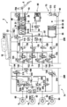
도 1 에 도시된 제동 시스템 (2) 은 탠덤 브레이크 마스터 실린더 (10) 가 작동되는 브레이크 페달 (6) 을 포함한다. 탠덤 브레이크 마스터 실린더 (10) 는 제 1 압력 챔버 또는 1 차 압력 챔버 (16) 를 갖고, 제 1 탄성 요소 (24) 에 의해 작용되는 1 차 압력 피스톤 (20) 이 제 1 압력 챔버 또는 1 차 압력 챔버 (16) 안으로 변위될 수 있다. 탠덤 브레이크 마스터 실린더 (10) 는 제 2 압력 챔버 또는 제 2 챔버 (30) 를 갖고, 제 2 탄성 요소 (40) 에 의해 작용되는 2 차 피스톤 (34), 특히 부유식 2 차 피스톤이 제 2 압력 챔버 또는 2 차 챔버 (30) 안으로 변위될 수 있다. 1 차 압력 피스톤 (20) 의 비작동 상태에서, 1 차 압력 챔버 (16) 는 유압 라인 (46) 을 통해 압력 매체 저장소 (18) 에 연결된다. 2 차 압력 피스톤 (34) 의 비작동 상태에서, 2 차 압력 챔버 (16) 는 유압 라인 (52) 을 통해 압력 매체 저장소 (18) 에 연결된다. The
제동 설비 또는 제동 시스템 (2) 은 4 개의 유압 작동식 휠 브레이크들 (60, 62, 64, 66) 을 포함한다. 제동 시스템 (2) 은 제동 설비의 정상 작동 동안 압력 제어를 위해 사용되는 메인 모듈 (70) 및 메인 모듈 (70) 이 오작동하거나 실패할 때 사용되는 보조 모듈 (74) 을 갖는다. The braking facility or
제동 시스템 (2) 은 또한 메인 모듈 (70) 에 다음과 같은 추가 컴포넌트들을 갖는다. 압력 제공 디바이스 (80) 는 전기 모터 (82), 모터 샤프트의 회전을 압력 공간 (88) 을 한정하는 압력 피스톤 (86) 의 병진으로 변환하는 다운스트림 회전-병진 메커니즘 (84) 을 갖는 선형 액츄에이터로서 설계된다. 압력 공간 (88) 은 보충 라인 (90) 을 통해 압력 매체 저장소 (18) 에 연결되며, 이것에는 체크 밸브 (92) 가 삽입된다. 회전-병진 메커니즘 (84) 은 볼 스크류로서 설계되는 것이 바람직하다.The
1 차 압력 챔버 (16) 는 시뮬레이터 (96) 에 유압식으로 연결되며, 1 차 압력 챔버 (16) 와 시뮬레이터 (16) 사이의 연결은 시뮬레이터 밸브 (98) 에 의해 분할될 수 있다. 휠 브레이크들 (60-66) 각각에는 바람직하게는 전원이 차단될 때 폐쇄되는 아웃렛 밸브 (100, 102, 104, 106) 및 바람직하게는 전원이 차단될 때 개방되는 인렛 밸브 (110, 112, 114, 116) 가 할당된다. 각각의 체크 밸브는 각각의 인렛 밸브 (110-116) 와 병렬로 연결된다.The
휠 브레이크들 (60, 62) 에는 제 1 브레이크 회로 (I) 이 할당되고 격리 밸브 (120) 에 의해 분리 가능한 방식으로 2 차 챔버 (30) 에 유압식으로 연결된다. 휠 브레이크 (64, 66) 는 제 2 브레이크 회로 (II) 에 할당되고 격리 밸브 (126) 에 의해 1 차 챔버 (16) 에 분리 가능한 방식으로 유압식으로 연결된다.The
압력 제공 디바이스 (80) 는 활성화 밸브 (130) 에 의해 휠 브레이크들 (60, 62) 에 유압식으로 연결될 수 있고 활성화 밸브 (136) 에 의해 휠 브레이크들 (64, 66) 에 유압식으로 연결될 수 있다.The
바람직하게는 리던던트 설계인 압력 센서 (140) 가 2 차 챔버 (30) 내의 압력을 측정한다. 바람직하게는 리던던트 설계인 압력 센서 (150) 가 시스템 압력으로 지칭되는 압력 챔버 (88) 내의 압력을 측정한다.The
밸브 (160) 가 스위칭되고 밸브 (136) 가 스위칭될 때, 압력을 제공하기 위한 압력 제공 디바이스의 용량을 점검하기 위해 추가의 자가 테스트가 수행될 수 있다. 밸브 (162) 는 예를 들어 압력 제공 디바이스가 이러한 자가 테스트의 일부로서 후단 위치로 다시 이동하는 경우 작동 유닛 내의 진공을 방지한다. 모터 위치 또는 회전 각도는 센서 (170) 의 도움으로 측정된다. 모터 권선 온도를 측정하기 위해 추가 센서 (172) 가 제공되는 것이 바람직하다. 휠 브레이크는 대각선으로 분할되며, 브레이크들 (60, 64) 은 전륜 브레이크들이다.When the
제동 시스템 (2) 의 보조 모듈 (74) 은 필요할 때, 특히 메인 모듈 (70) 의 결함 또는 전체 고장이 있을 때, 휠 브레이크들 (60, 64) 에서 휠 특정 브레이크 압력을, 필요한 경우, 제 1 작동 모드로 설정하도록 설계된다. 휠 브레이크들 (62, 66) 은 압력 제공 디바이스 (80) 또는 브레이크 마스터 실린더 (10) 에 유압식으로 직접 연결되며, 보조 모듈 (74) 에 의해 이들 브레이크에는 휠 브레이크 압력이 설정되지 않는다. 다른 작동 모드에서, 제동 시스템 (2) 의 보조 모듈 (74) 은, 메인 모듈 (70) 의 부분 고장이 있을 때 이들 밸브들 (100-162) 이 동작을 위해 여전히 존재하는 경우 모든 휠들 (60 내지 66) 에서 브레이크 압력을 설정하도록 설계된다.The
휠 브레이크 (60) 에서 볼 때, 압력 센서 (182), 제 1 공급 펌프 (200) 를 구비한 펌프 (190), 전원 해제될 때 개방되고 체크 밸브 (210) 가 병렬로 연결되는 격리 밸브 (194), 및 압력 센서 (198) 가 유압 라인 (180) 에서 배열되며, 이 유압 라인 (180) 에 의해, 필요한 경우, 휠 브레이크 (60) 는 브레이크 마스터 실린더 (10) 또는 압력 제공 디바이스 (80) 에 연결될 수 있다. 흡입 측에서, 펌프 (200) 는 유압식 흡입 라인 (204) 을 통해 압력 매체를 위한 부피 저장소 (208) 에 연결되고, 이는 압력 매체 저장소 (18) 에 라인을 통해 연결된다. 펌프를 스로틀링하는데 사용되며 전원이 차단될 때 폐쇄되는 전환 밸브 (212) 가 흡입 라인 (204) 에 삽입된다. 부피 저장소 (208) 는 또한 활성화 밸브 (220) 를 통해 휠 브레이크 (60) 에 연결되며, 활성화 밸브 (220) 는 바람직하게는 전원이 차단될 때 폐쇄된다. As seen from the
보조 모듈 (74) 은 휠 브레이크 (64) 와 관련하여 동일한 방식으로 설계되고, 대응하는 컴포넌트에는 동일한 참조 부호가 제공된다. 그러나, 여기서는, 휠 브레이크 (60) 와 달리, 라인 (180) 의 압력을 측정하는 압력 센서 (198) 가 제공되지 않는다. 대안적인 실시형태에서, 이 경우에도 추가 압력 센서 (198) 가 제공될 수 있다. 바람직한 실시형태에서, 적어도 하나의 압력 센서는 (압력 센서 (198) 의 경우에 예로써 도시된) 온도 센서 (242) 와 조합하여 형성된다. 이에 의해, 압력이 측정되는 지점에서 브레이크 유체의 온도를 측정하는 것도 가능하다. 모든 압력 센서는 온도 센서와 조합되거나, 두 센서 모두가 일체형 설계로 형성되는 것이 바람직하다.The
메인 모듈의 제 1 전자 개방 루프 및 폐쇄 루프 제어 유닛 (250) 은 특히 이동 센서 (264) 의 도움으로 및 압력 제공 디바이스 (80) 및 밸브들 (100-106, 110-16, 120, 126, 130, 136) 의 활성화에 의해 제동 요구를 감지하는데 사용된다.The first electronic open-loop and closed-
보조 모듈 (74) 의 제 2 전자 개방 루프 및 폐쇄 루프 제어 유닛 (260) 은 펌프 (200) 및 밸브들 (194, 220, 212) 을 제어하는데 사용된다. 입력 신호로서, 전자 개방 루프 및 폐쇄 루프 제어 유닛 (260) 은 센서 (264) 에 의해 감지된 드라이버 제동 요구를 수신한다. 적어도 하나의 방향으로 2 개의 개방 루프 및 폐쇄 루프 제어 유닛들 (250, 260) 사이에 신호 링크가 존재한다. The second electronic open-loop and closed-
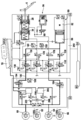
제동 시스템 (2) 은 도 2 의 정상 제동 프로세스에 대응하는 작동 위치에 도시되어 있다. 운전자는 브레이크 페달 (6) 을 작동시키고 압력 매체를 시뮬레이터 (96) 의 방향으로 1 차 챔버로부터 변위시킨다. 브레이크 마스터 실린더 (10) 의 2 개의 챔버들 (16, 30) 은 폐쇄 격리 밸브들 (120, 126) 에 의해 휠 브레이크들 (60-66) 로부터 유압식으로 분리된다. 활성화 밸브들 (130, 136) 은 개방되어 있으므로, 압력 제공 디바이스 (80) 에 의해 휠 브레이크들에서 압력이 능동적으로 빌드업될 수 있다. 이를 위해, 인렛 밸브들 (110-116) 은 개방되고 아웃렛 밸브들 (100-106) 은 폐쇄된다. 휠 특정의 압력 빌드업을 위해, 각각의 아웃렛 밸브 (100-106) 를 개방함으로써 휠 브레이크 (60-66) 에서 압력이 선택적으로 빌드업될 수 있다. 보조 모듈 (74) 의 밸브들 (194) 은 개방되어 있다. 이러한 방식으로 압력 매체 흐름이 발생하게 하려면, 밸브들 (120, 126) 은 도 2에 도시된 상황과 달리 폐쇄되어야 하고 밸브들 (130, 136) 은 개방되어야 한다. The
도 3에서, 제동 시스템 (2) 은 2 상 퍼징 사이클 또는 퍼징 프로세스 동안 도시되며, 여기서 시스템은 제동 시스템 (2) 이 압력 매체를 압력 매체 저장소 (18) 내로 배출할 수 있는지 여부를 점검한다. 이를 위해, 브레이크 회로 (I) 에서 압력 매체가 배출될 수 있는지에 대한 점검이 제 1 상에서 이루어진다. 이를 위해, 활성화 밸브 (130) 는 개방되는 한편, 활성화 밸브 (136) 및 격리 밸브 (120, 126) 는 폐쇄된다. 휠 브레이크 (60) 에 할당된 인렛 밸브 (110) 만이 개방되는 한편, 흡입 밸브들 (112, 114, 116) 은 폐쇄된다. 아웃렛 밸브 (100) 는 폐쇄되고 밸브 (194) 는 개방된다. 축압기 (208) 는 휠 브레이크 (60) 에 유압식으로 연결된다. 선형 액츄에이터 또는 압력 제공 디바이스 (80) 의 도움으로, 브레이크 유체는 이제 브레이크 회로 (I) 로 변위되고, 따라서 밸브의 스위칭으로 인해 브레이크 유체는 압력 매체 저장소 (18) 로 변위된다. In FIG. 3, the
압력 센서 (150) 는 제 1 시스템 압력 (Psys,1) 을 측정하며, 이는 실질적으로 압력 공간 (88) 에서 통용되는 압력에 대응한다. 압력 센서 (198) 는 보조 모듈 (74) 의 라인 (180) 에서 제 2 시스템 압력 (Psys,2) 을 측정한다. 선형 액츄에이터에 의해 결정된 체적 유량에서, 시스템 압력들 (Psys,1 및 Psys,2) 은 특히 브레이크 유체가 고점도인 경우에 이제 확립될 것이다. 그것은 바람직하게는 평가되는 미리 결정된 부피 유량이 설정되는 시간에 걸친 시스템 압력들 (Psys,1 및 Psys,2) 의 평균값들이다. The
보조 모듈 (74) 과 압력-매체 저장소 (18) 또는 저장소 사이의 막힌 라인의 경우, 두 압력들 (Psys,1 및 Psys,2) 은 거의 동일한 (상대적으로 높은) 값이다. 그렇지 않은 경우, 즉 저수지에 대한 유압 연결이 개방되면, Psys,1 에서 Psys,2 까지의 압력 구배가 확립된다. 따라서 허용 기준은 공식화되는 것이 바람직하다. In the case of a blocked line between the
Psys,1 < (Pakzept = c + r * (Psys,1 - Psys,2)).P sys,1 < (P akzept = c + r * (P sys,1- P sys,2 )).
여기서, r은 라인 저항의 관계로부터 도출된 수치 상수이다. R1 은 Psys,1 에서 Psys,2 로 가는 도중의 라인 및 밸브들에 의해 결정되고 R2 는 Psys,2 에서 저장소 (18) 로 가는 도중의 라인 및 밸브들에 의해 결정된다. 다음이 적용된다: r = (R1 + R2)/R2 Here, r is a numerical constant derived from the relationship of the line resistance. R 1 is determined by lines and valves on the way from P sys,1 to P sys,2 and R 2 is determined by lines and valves on the way from P sys,2 to
r > 1 이고 c는 압력 단위의 상수이고 c > 0 이다.r> 1 And c is a constant in pressure units and c> 0.
이 퍼징 프로세스 이후, 시스템은 제 2 브레이크 회로 (II) 에서 압력 매체를 저장소로 변위시킬 수 있는지 여부를 점검한다. 이를 위해, 활성화 밸브 (136) 가 개방되는 한편, 활성화 밸브 (130) 및 격리 밸브 (120, 126) 는 폐쇄된다. 전술한 바와 같이, 밸브 (194) 는 보조 모듈에서 개방된다. 축압기 (208) 는 휠 브레이크 (64) 에 유압식으로 연결된다. 브레이크 회로 (II) 에는 압력 센서가 없기 때문에, 브레이크 회로 (II) 에서의 퍼징 프로세스에 대해 측정된 값은 전술한 허용 기준의 적용을 위해 사용된다.After this purging process, the system checks in the second brake circuit (II) whether it can displace the pressure medium into the reservoir. To this end, the
Claims (15)
이 제동 시스템은 메인 모듈 (70) 을 포함하고, 그리고 보조 모듈 (74) 을 더 포함하고,
상기 메인 모듈 (70) 은:
상기 보조 모듈 (74) 은, 두 개의 휠 브레이크들 (60, 64) 각각에 대해:
적어도 하나의 변수 (Psys,1, Psys,2) 가 상기 제동 시스템 (2) 의 기능을 평가하기 위해 측정되고, 적어도 하나의 허용 기준이 사용되고, 상기 변수 (Psys,1, Psys,2) 가 상기 허용 기준을 만족하는지 여부가 점검되고, 브레이크 유체의 점도를 나타내는 적어도 하나의 변수가 결정되고, 그리고 상기 적어도 하나의 허용 기준은 상기 점도를 나타내는 변수에 의존하는, 자동차용 제동 시스템의 기능을 점검하는 방법.As a method for checking the function of the braking system for automobiles (2),
This braking system includes a main module 70, and further includes an auxiliary module 74,
The main module 70 is:
The auxiliary module 74, for each of the two wheel brakes (60, 64):
At least one variable (P sys,1 , P sys,2 ) is measured to evaluate the function of the braking system 2, at least one acceptance criterion is used, and the variable (P sys,1 , P sys, It is checked whether 2 ) satisfies the above acceptance criterion, at least one variable indicating the viscosity of the brake fluid is determined, and the at least one acceptance criterion depends on the variable indicating the viscosity. How to check the function.
상기 압력 제공 디바이스 (80) 에 의해 브레이크 유체가 압력 매체 저장소 (18) 로 변위되는 퍼징 프로세스가 수행되고, 제 1 시스템 압력 (Psys,1) 이 측정되고, 제 2 시스템 압력 (Psys,2) 이 측정되고, 상기 제 1 시스템 압력 (Psys,1) 이 허용 압력보다 낮으면 허용 기준이 만족된 것으로 카운트되고, 허용 압력은 상기 제 1 시스템 압력과 상기 제 2 시스템 압력 (Psys,2) 사이의 압력차에 의존하는, 자동차용 제동 시스템의 기능을 점검하는 방법.According to claim 1,
A purging process in which the brake fluid is displaced into the pressure medium reservoir 18 by the pressure providing device 80 is performed, the first system pressure P sys,1 is measured, and the second system pressure P sys,2 ) Is measured, and if the first system pressure (P sys,1 ) is lower than the allowable pressure, the acceptance criterion is counted, and the allowable pressure is the first system pressure and the second system pressure (P sys,2). How to check the function of the braking system for an automobile, depending on the pressure difference between ).
상기 허용 압력은 제 1 상수 (c) 와, 상기 제 1 시스템 압력 (Psys,1) 과 상기 제 2 시스템 압력 (Psys,2) 사이의 압력차와 제 2 상수 (r) 의 곱의 합으로부터 형성되는, 자동차용 제동 시스템의 기능을 점검하는 방법. According to claim 2,
The allowable pressure is the sum of the product of the second constant (r) and the pressure difference between the first constant (c) and the first system pressure (P sys,1 ) and the second system pressure (P sys,2 ). Formed from, how to check the function of the braking system for automobiles.
상기 제 1 시스템 압력 (Psys,1) 은 상기 메인 모듈 (70) 의 유압 라인에서 측정되고, 상기 제 2 시스템 압력 (Psys,2) 은 상기 보조 모듈 (74) 의 유압 라인 (180) 에서 측정되는, 자동차용 제동 시스템의 기능을 점검하는 방법.The method according to claim 2 or 3,
The first system pressure (P sys, 1 ) is measured in the hydraulic line of the main module 70, and the second system pressure (P sys, 2 ) is in the hydraulic line 180 of the auxiliary module 74. How to check the function of the braking system for the vehicle being measured.
상기 제 2 시스템 압력 (Psys,2) 이 측정되는 압력 센서는 상기 보조 모듈 내의 제 1 브레이크 회로 (I) 에 배열되고, 그리고 상기 제 1 브레이크 회로 (I) 에서 측정된 시스템 압력의 값은 또한 제 2 브레이크 회로 (II) 에 대한 퍼징 프로세스에서 사용되는, 자동차용 제동 시스템의 기능을 점검하는 방법.The method of claim 4,
The pressure sensor in which the second system pressure (P sys,2 ) is measured is arranged in the first brake circuit (I) in the auxiliary module, and the value of the system pressure measured in the first brake circuit (I) is also A method for checking the function of a braking system for an automobile, which is used in the purging process for the second brake circuit (II).
압력 빌드업 프로세스는 상기 압력 제공 디바이스 (80) 의 도움으로 수행되고, 브레이크 유체는 미리 결정된 기간 (t) 동안 상기 압력 제공 디바이스 (80) 에 의해 적어도 하나의 휠 브레이크 (60, 64) 로 전달되고, 상기 미리 결정된 기간 (t) 이후 존재하는 시스템 압력 (Psys,1) 이 측정되고, 측정된 압력이 예상 압력보다 큰 경우 허용 기준이 만족되는 것으로 카운트되며, 예상 압력은 상기 기간 및 상기 압력 제공 디바이스 (80) 의 예상 전달 속도에 의존하는, 자동차용 제동 시스템의 기능을 점검하는 방법.The method according to claim,
A pressure build-up process is performed with the aid of the pressure providing device 80, brake fluid is delivered to the at least one wheel brake 60, 64 by the pressure providing device 80 for a predetermined period t , The system pressure (P sys,1 ) present after the predetermined period (t) is measured, and if the measured pressure is greater than the expected pressure, the acceptance criterion is counted, and the estimated pressure is provided for the period and the pressure A method of checking the function of a braking system for a vehicle, depending on the expected delivery speed of the device (80).
예상 전달 부피 (Ve) 는 점도 및/또는 온도에 의존하는 전달 속도 (Q) 와 미리 결정된 기간 (t) 의 곱으로부터 계산되며, 상기 예상 압력은 미리 결정된 압력-부피 특성 (pV) 의 도움으로 상기 예상 전달 부피로부터 계산되는, 자동차용 제동 시스템의 기능을 점검하는 방법.The method of claim 6,
The expected delivery volume (V e ) is calculated from the product of the viscosity and/or temperature dependent delivery rate (Q) and a predetermined period (t), which is estimated with the help of a predetermined pressure-volume characteristic (pV). A method for checking the function of a braking system for a vehicle, calculated from the estimated delivery volume.
상기 예상 전달 부피는 방출 클리어런스 부피 (VL) 에 의해 보정되는, 자동차용 제동 시스템의 기능을 점검하는 방법. The method of claim 7,
The expected delivery volume is corrected by the release clearance volume (V L ), how to check the function of the braking system for the vehicle.
상기 브레이크 유체의 온도 (T) 는 적어도 하나의 온도 센서에 의해 측정되는, 자동차용 제동 시스템의 기능을 점검하는 방법.The method according to any one of claims 1 to 8,
A method for checking the function of a braking system for a vehicle, wherein the temperature (T) of the brake fluid is measured by at least one temperature sensor.
상기 온도 (T) 는 다수의 온도 센서들의 도움으로 측정되며, 그 측정된 값들로부터 평균값이 그후 형성되는, 자동차용 제동 시스템의 기능을 점검하는 방법.The method of claim 9,
The temperature (T) is measured with the help of multiple temperature sensors, and an average value is then formed from the measured values, to check the function of the braking system for a vehicle.
상기 브레이크 유체의 점도는 특성에 의해 온도로부터 결정되는, 자동차용 제동 시스템의 기능을 점검하는 방법.The method according to any one of claims 1 to 10,
A method for checking the function of a braking system for an automobile, wherein the viscosity of the brake fluid is determined from temperature by characteristics.
상기 메인 모듈 (70) 에는 적어도 하나의 압력 센서가 배열되고, 상기 보조 모듈 (71) 에는 적어도 하나의 압력 센서가 배열되는, 자동차용 제동 시스템의 기능을 점검하는 방법.The method according to any one of claims 9 to 11,
At least one pressure sensor is arranged on the main module 70, and at least one pressure sensor is arranged on the auxiliary module 71.
각각의 온도 센서는 일체형 설계의 각각의 압력 센서에 의해 형성되는, 자동차용 제동 시스템의 기능을 점검하는 방법.The method of claim 12,
Each temperature sensor is formed by a respective pressure sensor in an integral design, a method for checking the function of a braking system for an automobile.
메인 모듈 (70) 을 포함하고, 보조 모듈 (74) 을 더 포함하고,
상기 메인 모듈 (70) 은:
상기 보조 모듈 (74) 은, 두 개의 휠 브레이크들 (60, 64) 각각에 대해:
제 1 항 내지 제 13 항 중 어느 한 항에 청구된 방법이 하드웨어 및/또는 소프트웨어로 구현되는, 개방 루프 및 폐쇄 루프 제어 유닛을 구비하는, 제동 시스템.As a vehicle braking system (2),
It includes a main module 70, and further includes an auxiliary module 74,
The main module 70 is:
The auxiliary module 74, for each of the two wheel brakes (60, 64):
A braking system, wherein the method claimed in claim 1 is implemented in hardware and/or software, with open and closed loop control units.
상기 압력 제공 디바이스 (80) 는 선형 액츄에이터로 설계되는, 제동 시스템.The method of claim 14,
The pressure providing device 80 is designed as a linear actuator, a braking system.
Applications Claiming Priority (3)
| Application Number | Priority Date | Filing Date | Title |
|---|---|---|---|
| DE102017220308.0A DE102017220308A1 (en) | 2017-11-15 | 2017-11-15 | Method for checking the functionality of a brake system and brake system |
| DE102017220308.0 | 2017-11-15 | ||
| PCT/EP2018/080457 WO2019096651A1 (en) | 2017-11-15 | 2018-11-07 | Method for checking the functionality of a braking system, and braking system |
Publications (2)
| Publication Number | Publication Date |
|---|---|
| KR20200067188A true KR20200067188A (en) | 2020-06-11 |
| KR102398464B1 KR102398464B1 (en) | 2022-05-16 |
Family
ID=64559639
Family Applications (1)
| Application Number | Title | Priority Date | Filing Date |
|---|---|---|---|
| KR1020207013759A KR102398464B1 (en) | 2017-11-15 | 2018-11-07 | How to check the function of the braking system and the braking system |
Country Status (6)
| Country | Link |
|---|---|
| US (1) | US11465602B2 (en) |
| EP (1) | EP3710321B1 (en) |
| KR (1) | KR102398464B1 (en) |
| CN (1) | CN111356617B (en) |
| DE (1) | DE102017220308A1 (en) |
| WO (1) | WO2019096651A1 (en) |
Families Citing this family (10)
| Publication number | Priority date | Publication date | Assignee | Title |
|---|---|---|---|---|
| DE102017000472A1 (en) * | 2017-01-19 | 2018-07-19 | Lucas Automotive Gmbh | Hydraulic vehicle brake system and method for operating and testing the same |
| DE102018010168A1 (en) * | 2018-12-28 | 2020-07-02 | Zf Active Safety Gmbh | Hydraulic motor vehicle brake system and method for operating the same |
| DE102019214792A1 (en) * | 2019-09-26 | 2021-04-01 | Continental Teves Ag & Co. Ohg | Braking system and motor vehicle |
| DE102020211431A1 (en) | 2020-09-11 | 2022-03-17 | Continental Teves Ag & Co. Ohg | Procedures for performing service routines |
| US20220135016A1 (en) * | 2020-10-30 | 2022-05-05 | Westinghouse Air Brake Technologies Corporation | Vehicle braking calibration system |
| US20220234559A1 (en) * | 2021-01-27 | 2022-07-28 | Advics North America, Inc. | Series-connected brake actuators and automatic brake hold method employing same |
| US11801817B2 (en) * | 2021-03-04 | 2023-10-31 | ZF Active Safety US Inc. | Vehicle braking system |
| WO2023057886A1 (en) * | 2021-10-05 | 2023-04-13 | ロベルト・ボッシュ・ゲゼルシャフト・ミト・ベシュレンクテル・ハフツング | Brake fluid pressure control device and brake system |
| DE102022203990A1 (en) | 2022-01-13 | 2023-07-13 | Continental Automotive Technologies GmbH | Low temperature hydraulic braking system and method of operating such a braking system |
| DE102022123532A1 (en) * | 2022-09-14 | 2024-03-14 | Heinz Leiber | Braking system and valve with switchable holding force |
Citations (3)
| Publication number | Priority date | Publication date | Assignee | Title |
|---|---|---|---|---|
| US6901789B1 (en) * | 1999-03-17 | 2005-06-07 | Continental Teves Ag & Co. Ohg | Method for determining parameters |
| US20160052501A1 (en) * | 2014-08-25 | 2016-02-25 | Robert Bosch Gmbh | Method and device for ascertaining at least one variable regarding a state of a brake fluid in a brake system of a vehicle |
| WO2017144201A1 (en) * | 2016-02-26 | 2017-08-31 | Continental Teves Ag & Co. Ohg | Add-on module for an electrohydraulic brake assembly, and brake assembly system comprising an add-on module of said type |
Family Cites Families (12)
| Publication number | Priority date | Publication date | Assignee | Title |
|---|---|---|---|---|
| JP3915209B2 (en) * | 1997-12-03 | 2007-05-16 | 住友電気工業株式会社 | Brake fluid temperature detection method and brake fluid pressure control method |
| JP2002538040A (en) * | 1999-03-04 | 2002-11-12 | コンティネンタル・テーベス・アクチエンゲゼルシヤフト・ウント・コンパニー・オッフェネ・ハンデルスゲゼルシヤフト | Circuit device for automobile brake device |
| DE10011796B4 (en) * | 1999-03-17 | 2009-05-28 | Continental Teves Ag & Co. Ohg | Method and arrangement for determining the characteristic quantities |
| DE102009028542A1 (en) * | 2009-08-14 | 2011-02-17 | Robert Bosch Gmbh | Method and device for controlling a brake system |
| DE102010001943A1 (en) | 2010-02-15 | 2011-08-18 | Robert Bosch GmbH, 70469 | Method for operating a hydraulic brake system of a vehicle and control device for a hydraulic brake system of a vehicle |
| DE102012205862A1 (en) * | 2011-04-19 | 2012-10-25 | Continental Teves Ag & Co. Ohg | Brake system for motor vehicles and method for operating a brake system |
| DE102012205859A1 (en) * | 2011-04-19 | 2012-10-25 | Continental Teves Ag & Co. Ohg | Brake system for motor vehicles and method for operating a brake system |
| DE102011078890A1 (en) | 2011-07-08 | 2013-01-10 | Robert Bosch Gmbh | Monitoring device for at least one subunit of a hydraulic brake system and method for investigating a functionality of at least one subunit of a hydraulic brake system |
| DE102013204778A1 (en) | 2012-03-22 | 2013-09-26 | Continental Teves Ag & Co. Ohg | A method for haptic information of the driver of a motor vehicle |
| DE102013222061A1 (en) | 2013-03-25 | 2014-09-25 | Continental Teves Ag & Co. Ohg | Method for operating a brake system for motor vehicles |
| DE102014212537A1 (en) * | 2014-06-30 | 2015-12-31 | Continental Teves Ag & Co. Ohg | Brake system for a motor vehicle |
| DE102014216843A1 (en) | 2014-08-25 | 2016-02-25 | Robert Bosch Gmbh | An apparatus and method for determining at least one of a state of a brake fluid in a brake system of a vehicle |
-
2017
- 2017-11-15 DE DE102017220308.0A patent/DE102017220308A1/en active Pending
-
2018
- 2018-11-07 WO PCT/EP2018/080457 patent/WO2019096651A1/en unknown
- 2018-11-07 KR KR1020207013759A patent/KR102398464B1/en active IP Right Grant
- 2018-11-07 CN CN201880073851.5A patent/CN111356617B/en active Active
- 2018-11-07 EP EP18811445.8A patent/EP3710321B1/en active Active
- 2018-11-07 US US16/763,767 patent/US11465602B2/en active Active
Patent Citations (3)
| Publication number | Priority date | Publication date | Assignee | Title |
|---|---|---|---|---|
| US6901789B1 (en) * | 1999-03-17 | 2005-06-07 | Continental Teves Ag & Co. Ohg | Method for determining parameters |
| US20160052501A1 (en) * | 2014-08-25 | 2016-02-25 | Robert Bosch Gmbh | Method and device for ascertaining at least one variable regarding a state of a brake fluid in a brake system of a vehicle |
| WO2017144201A1 (en) * | 2016-02-26 | 2017-08-31 | Continental Teves Ag & Co. Ohg | Add-on module for an electrohydraulic brake assembly, and brake assembly system comprising an add-on module of said type |
Also Published As
| Publication number | Publication date |
|---|---|
| WO2019096651A1 (en) | 2019-05-23 |
| EP3710321A1 (en) | 2020-09-23 |
| CN111356617B (en) | 2022-09-23 |
| DE102017220308A1 (en) | 2019-05-16 |
| US20200361439A1 (en) | 2020-11-19 |
| US11465602B2 (en) | 2022-10-11 |
| CN111356617A (en) | 2020-06-30 |
| EP3710321B1 (en) | 2023-01-11 |
| KR102398464B1 (en) | 2022-05-16 |
Similar Documents
| Publication | Publication Date | Title |
|---|---|---|
| KR102398464B1 (en) | How to check the function of the braking system and the braking system | |
| US10246067B2 (en) | Brake system and method for operating a brake system | |
| US10166959B2 (en) | Method for diagnosing electric brake system | |
| JP4495269B2 (en) | Control method and apparatus for automobile brake device | |
| US9834189B2 (en) | Electro-hydraulic brake system including isolated circuits and method of controlling the same | |
| US9145121B2 (en) | Method for monitoring a brake system and brake system | |
| US9868426B2 (en) | Pressure provision device and brake system | |
| JP4587501B2 (en) | Brake device inspection method and device | |
| JP5734319B2 (en) | Brake device for vehicle | |
| US9981642B2 (en) | Electric brake system and method thereof | |
| US20170001615A1 (en) | Calibration method for an electro-hydraulic motor vehicle braking system and associated calibration device | |
| CN113573959B (en) | Fail safe braking system | |
| CN107757595B (en) | Method for detecting leakage in a hydraulic brake system | |
| CN108001436B (en) | Electronic brake system and control method thereof | |
| WO2019186455A1 (en) | Brake system and method for responding to external boost requests during predetermined loss or degraded boost assist conditions | |
| CN112399936B (en) | Method for controlling braking force in electrohydraulic braking device of motor vehicle | |
| JPH11348752A (en) | Control method and device for automobile brake device | |
| US20080040012A1 (en) | Method for Supporting a Brake System in Case of Reduced Effectiveness of the Vehicle Brake System | |
| US20220135010A1 (en) | Pressure supply device with double stroke piston for a brake system | |
| US20040237638A1 (en) | Method for testing a current regulator in a electronically controllable valve in a hydraulic vehicle brake system | |
| KR20230150855A (en) | Method for reducing pressure peak of hydraulic brake system and brake system therefor | |
| US20220126804A1 (en) | Fail-safe braking system | |
| CN117751063A (en) | Method for checking the contact of circuit branches associated with each other of separate brake circuits of a brake-assist system, which has two actuator units in contact with each other in a pressure medium-conducting manner, for brake pressure generation and brake pressure regulation, in particular for motor vehicles, for electronic slip regulation | |
| KR100863551B1 (en) | Method for managing diagnostic trouble codes | |
| CN116080607A (en) | Electronic brake for vehicle and control method thereof |
Legal Events
| Date | Code | Title | Description |
|---|---|---|---|
| E902 | Notification of reason for refusal | ||
| E701 | Decision to grant or registration of patent right | ||
| GRNT | Written decision to grant |