KR20200067031A - Combinational operating patch - Google Patents
Combinational operating patch Download PDFInfo
- Publication number
- KR20200067031A KR20200067031A KR1020180153892A KR20180153892A KR20200067031A KR 20200067031 A KR20200067031 A KR 20200067031A KR 1020180153892 A KR1020180153892 A KR 1020180153892A KR 20180153892 A KR20180153892 A KR 20180153892A KR 20200067031 A KR20200067031 A KR 20200067031A
- Authority
- KR
- South Korea
- Prior art keywords
- patch
- light irradiation
- heat transfer
- irradiation unit
- treatment
- Prior art date
Links
Images


Classifications
-
- A—HUMAN NECESSITIES
- A61—MEDICAL OR VETERINARY SCIENCE; HYGIENE
- A61N—ELECTROTHERAPY; MAGNETOTHERAPY; RADIATION THERAPY; ULTRASOUND THERAPY
- A61N5/00—Radiation therapy
- A61N5/06—Radiation therapy using light
- A61N5/0613—Apparatus adapted for a specific treatment
- A61N5/0619—Acupuncture
-
- A—HUMAN NECESSITIES
- A61—MEDICAL OR VETERINARY SCIENCE; HYGIENE
- A61F—FILTERS IMPLANTABLE INTO BLOOD VESSELS; PROSTHESES; DEVICES PROVIDING PATENCY TO, OR PREVENTING COLLAPSING OF, TUBULAR STRUCTURES OF THE BODY, e.g. STENTS; ORTHOPAEDIC, NURSING OR CONTRACEPTIVE DEVICES; FOMENTATION; TREATMENT OR PROTECTION OF EYES OR EARS; BANDAGES, DRESSINGS OR ABSORBENT PADS; FIRST-AID KITS
- A61F7/00—Heating or cooling appliances for medical or therapeutic treatment of the human body
- A61F7/007—Heating or cooling appliances for medical or therapeutic treatment of the human body characterised by electric heating
-
- A—HUMAN NECESSITIES
- A61—MEDICAL OR VETERINARY SCIENCE; HYGIENE
- A61N—ELECTROTHERAPY; MAGNETOTHERAPY; RADIATION THERAPY; ULTRASOUND THERAPY
- A61N5/00—Radiation therapy
- A61N5/06—Radiation therapy using light
- A61N5/0613—Apparatus adapted for a specific treatment
- A61N5/0625—Warming the body, e.g. hyperthermia treatment
-
- A—HUMAN NECESSITIES
- A61—MEDICAL OR VETERINARY SCIENCE; HYGIENE
- A61F—FILTERS IMPLANTABLE INTO BLOOD VESSELS; PROSTHESES; DEVICES PROVIDING PATENCY TO, OR PREVENTING COLLAPSING OF, TUBULAR STRUCTURES OF THE BODY, e.g. STENTS; ORTHOPAEDIC, NURSING OR CONTRACEPTIVE DEVICES; FOMENTATION; TREATMENT OR PROTECTION OF EYES OR EARS; BANDAGES, DRESSINGS OR ABSORBENT PADS; FIRST-AID KITS
- A61F7/00—Heating or cooling appliances for medical or therapeutic treatment of the human body
- A61F2007/0086—Heating or cooling appliances for medical or therapeutic treatment of the human body with a thermostat
-
- A—HUMAN NECESSITIES
- A61—MEDICAL OR VETERINARY SCIENCE; HYGIENE
- A61F—FILTERS IMPLANTABLE INTO BLOOD VESSELS; PROSTHESES; DEVICES PROVIDING PATENCY TO, OR PREVENTING COLLAPSING OF, TUBULAR STRUCTURES OF THE BODY, e.g. STENTS; ORTHOPAEDIC, NURSING OR CONTRACEPTIVE DEVICES; FOMENTATION; TREATMENT OR PROTECTION OF EYES OR EARS; BANDAGES, DRESSINGS OR ABSORBENT PADS; FIRST-AID KITS
- A61F7/00—Heating or cooling appliances for medical or therapeutic treatment of the human body
- A61F2007/0088—Radiating heat
-
- A—HUMAN NECESSITIES
- A61—MEDICAL OR VETERINARY SCIENCE; HYGIENE
- A61N—ELECTROTHERAPY; MAGNETOTHERAPY; RADIATION THERAPY; ULTRASOUND THERAPY
- A61N5/00—Radiation therapy
- A61N5/06—Radiation therapy using light
- A61N2005/0626—Monitoring, verifying, controlling systems and methods
-
- A—HUMAN NECESSITIES
- A61—MEDICAL OR VETERINARY SCIENCE; HYGIENE
- A61N—ELECTROTHERAPY; MAGNETOTHERAPY; RADIATION THERAPY; ULTRASOUND THERAPY
- A61N5/00—Radiation therapy
- A61N5/06—Radiation therapy using light
- A61N2005/0635—Radiation therapy using light characterised by the body area to be irradiated
- A61N2005/0643—Applicators, probes irradiating specific body areas in close proximity
-
- A—HUMAN NECESSITIES
- A61—MEDICAL OR VETERINARY SCIENCE; HYGIENE
- A61N—ELECTROTHERAPY; MAGNETOTHERAPY; RADIATION THERAPY; ULTRASOUND THERAPY
- A61N5/00—Radiation therapy
- A61N5/06—Radiation therapy using light
- A61N2005/065—Light sources therefor
- A61N2005/0651—Diodes
- A61N2005/0652—Arrays of diodes
Abstract
Description
본 발명은 복합 시술 패치에 관한 것으로, 보다 구체적으로 광 시술과 온열 시술이 동시에 수행될 수 있는 광/온열 복합 시술 패치에 관한 것이다.The present invention relates to a composite treatment patch, and more particularly, to a light/heat composite treatment patch in which a light treatment and a heat treatment can be performed simultaneously.
일반적으로 파스 또는 통증 패치라 불리는 외용제는 인체에 부착되어 환부의 통증 완화 목적을 갖는 의약품이다. 파스는 접착액이 혼합된 파스액이 도포된 밴드 형태로 이루어지며, 사용시 환부에 부착시켜 사용하게 된다. 파스는 도포된 파스액의 성분이나 종류에 따른 온찜질용 또는 냉찜질용 등이 있으며, 최근에는 보다 높은 혈류 개선 효과를 위해 자석이나 침 등을 중앙에 배치시킨 형태도 나오고 있다.In general, an external preparation called pars or a pain patch is a medicine that is attached to the human body and has the purpose of alleviating pain in the affected area. The parse is made in the form of a band coated with the parse liquid mixed with the adhesive liquid, and is used by attaching it to the affected area during use. The parsing agent includes warming or cold compressing according to the composition or type of the applied parsing liquid, and recently, a type in which a magnet or saliva is disposed in the center for a higher blood flow improvement effect is also available.
이러한 파스는 도포된 접착액이나 파스액, 부착시 공기 순환 미흡 등으로 인한 피부 트러블, 크고 작은 화상, 피부 발진과 짓무름 등의 부작용이 발생된다. 특히, 선천적으로 피부가 약한 사람이나 어린이와 같은 사람에게는 이러한 부작용으로 인해 사용이 어렵다는 문제가 있다. 또한, 일반적인 파스는 근본적인 치료가 아닌 제한적인 효과뿐이고, 대부분 1회용으로 쓰고 버려야 하므로 장기 사용시 비용적 부담과 함께 친환경적이지 못하다는 단점이 있다.These pars cause side effects such as skin problems caused by insufficient adhesion of the applied adhesive or pars, air circulation when attached, large and small burns, and skin rashes and wrinkles. In particular, there is a problem in that it is difficult to use due to these side effects to people with congenital weak skin or children. In addition, general pars has only a limited effect, not a fundamental treatment, and most of them have to be used for disposable use, so there is a disadvantage in that they are not environmentally friendly with a cost burden during long-term use.
한편, 저출력 레이저(low level laser, LLL)는 특정 파장 범위에 따라, 통증 완화, 혈류 개선, 혈류 강화, 피부 재생, 세포 활성화, 지방 분해, 그리고 세포 자극 등의 다양한 효과들이 있는 것으로 여러 임상 자료를 통해 알려져 있다. 피부 조직의 파괴, 의도적 손상 또는 괴사 목적으로 사용되는 고출력 레이저에 비해, 100mW 이하의 상대적으로 낮은 출력을 갖는 600nm 파장대 이상의 저출력 레이저는 상대적으로 안전하면서도 신진대사 촉진과 세포 활성화, 그리고 면역력 상승의 효과를 갖고 있어, 손상된 세포 조직을 회복시키는 기능을 갖고 있다. 특히, 800nm 이상 파장대의 저출력 레이저를 경혈에 선택적으로 조사하면 침 또는 뜸 치료와 같은 효과를 발휘하여, 피부나 근육의 통증을 완화시키고 환부 완치를 촉진시키는 기능을 하는 것으로 알려져 있다.On the other hand, low level laser (LLL) has various effects such as pain relief, blood flow improvement, blood flow enhancement, skin regeneration, cell activation, fat breakdown, and cell stimulation according to a specific wavelength range. Is known through. Compared to high-power lasers used for the purpose of destruction, intentional damage or necrosis of skin tissues, low-power lasers over the 600nm wavelength band with a relatively low power of less than 100mW are relatively safe yet have the effect of promoting metabolism, activating cells, and boosting immunity. It has a function of restoring damaged cell tissue. In particular, it is known that selectively irradiating a low-power laser with a wavelength of 800 nm or more to acupuncture points exerts an effect such as acupuncture or moxibustion treatment, thereby alleviating pain in the skin and muscles and promoting the cure of the affected area.
본 발명은 광을 이용한 광 시술 및 열을 이용한 온열 시술이 동시에 구현 가능한 복합 시술 패치를 제공하는 것이다.The present invention is to provide a composite treatment patch that can be implemented simultaneously with light treatment using light and heat treatment using heat.
본 발명의 일 측면에 따르면, 피시술자의 시술 부위와 대향하는 저면에 투과홀이 형성되는 패치 본체, 패치 본체의 내부에 배치되는 회로 기판, 회로 기판에 투과홀의 위치와 대응되도록 실장되어 투과홀을 통해 시술 부위로 광을 조사하는 광 조사 유닛, 및 패치 본체의 저면에 배치되고 열 전도성 재질로 이루어져 광 조사 유닛에서 발생되는 열을 시술 부위로 제공하는 열 전달 유닛을 포함하는 복합 시술 패치가 제공된다.According to an aspect of the present invention, a patch body in which a transmission hole is formed on a bottom surface opposite to a treatment site of a person to be treated, a circuit board disposed inside the patch body, and mounted to correspond to the position of the transmission hole in the circuit board, through the transmission hole A composite treatment patch is provided that includes a light irradiation unit that irradiates light to the treatment site, and a heat transfer unit that is disposed on the bottom surface of the patch body and is made of a thermally conductive material to provide heat generated by the light irradiation unit to the treatment site.
열 전달 유닛은 시술 부위에 대향하도록 배치되는 판형 부재를 포함할 수 있다.The heat transfer unit may include a plate-shaped member disposed to face the treatment site.
열 전달 유닛에는 투과홀의 위치와 대응되도록 관통홀이 형성되어, 광 조사 유닛은 투과홀 및 관통홀을 통해 시술 부위로 광을 조사할 수 있다.A through-hole is formed in the heat transfer unit to correspond to the position of the through-hole, and the light irradiation unit may irradiate light to the treatment site through the through-hole and through-hole.
광 조사 유닛은 투과홀 및 관통홀에 삽입될 수 있다.The light irradiation unit may be inserted into the through hole and through hole.
광 조사 유닛은 관통홀에 억지 끼워맞춤되어 결합될 수 있다.The light irradiation unit may be fitted to the through hole forcibly.
광 조사 유닛의 단부는 열 전달 유닛의 표면과 동일면 상에 위치될 수 있다.The end of the light irradiation unit may be located on the same side as the surface of the heat transfer unit.
열 전달 유닛은 광 조사 유닛과 접하도록 형성되어 광 조사 유닛에서 발생되는 열을 직접 전달받을 수 있다.The heat transfer unit is formed to be in contact with the light irradiation unit, and can directly receive heat generated by the light irradiation unit.
열 전달 유닛에는 광 조사 유닛을 향해 돌출되어 광 조사 유닛과 직접 접하는 돌기가 형성될 수 있다.The heat transfer unit may be formed with a protrusion protruding toward the light irradiation unit and directly contacting the light irradiation unit.
열 전달 유닛은 패치 본체보다 큰 중량을 가질 수 있다.The heat transfer unit can have a larger weight than the patch body.
복합 시술 패치는, 광 조사 유닛의 방열을 위하여 패치 본체의 내부에 설치되는 방열 유닛을 더 포함할 수 있다.The composite treatment patch may further include a heat dissipation unit installed inside the patch body for heat dissipation of the light irradiation unit.
방열 유닛은 회로 기판과 열 전달 유닛 사이에 배치되는 판형 부재를 포함할 수 있다.The heat dissipation unit may include a plate-shaped member disposed between the circuit board and the heat transfer unit.
방열 유닛에는 투과홀의 위치와 대응되도록 수용홀이 형성되며, 광 조사 유닛은 수용홀에 삽입될 수 있다.In the heat dissipation unit, an accommodation hole is formed to correspond to the position of the transmission hole, and the light irradiation unit may be inserted into the accommodation hole.
광 조사 유닛은 수용홀에 억지 끼워맞춤되어 결합될 수 있다.The light irradiation unit can be fitted to the receiving hole forcibly.
본 발명에 따르면, 광을 이용한 광 시술 및 열을 이용한 온열 시술이 동시에 구현 가능한 복합 시술 패치가 제공된다.According to the present invention, there is provided a composite treatment patch capable of simultaneously implementing light treatment using light and heat treatment using heat.
도 1은 본 발명의 일 실시예에 따른 복합 시술 패치를 나타낸 분해 사시도.
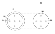
도 2는 본 발명의 일 실시예에 따른 복합 시술 패치를 나타낸 저면도.
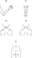
도 3은 본 발명의 일 실시예에 따른 복합 시술 패치의 적응증별 시술 형태를 나타내는 도면.
도 4는 본 발명의 일 실시예에 따른 복합 시술 패치를 나타낸 단면도.
도 5는 본 발명의 다른 실시예에 따른 복합 시술 패치를 나타낸 단면도.1 is an exploded perspective view showing a composite surgical patch according to an embodiment of the present invention.
Figure 2 is a bottom view showing a composite treatment patch according to an embodiment of the present invention.
Figure 3 is a view showing a treatment type for each indication of the complex treatment patch according to an embodiment of the present invention.
Figure 4 is a cross-sectional view showing a composite treatment patch according to an embodiment of the present invention.
Figure 5 is a cross-sectional view showing a composite treatment patch according to another embodiment of the present invention.
본 발명은 다양한 변환을 가할 수 있고 여러 가지 실시예를 가질 수 있는 바, 특정 실시예들을 도면에 예시하고 상세한 설명에 상세하게 설명하고자 한다. 그러나, 이는 본 발명을 특정한 실시 형태에 대해 한정하려는 것이 아니며, 본 발명의 사상 및 기술 범위에 포함되는 모든 변환, 균등물 내지 대체물을 포함하는 것으로 이해되어야 한다. 본 발명을 설명함에 있어서 관련된 공지 기술에 대한 구체적인 설명이 본 발명의 요지를 흐릴 수 있다고 판단되는 경우 그 상세한 설명을 생략한다.The present invention can be applied to various transformations and may have various embodiments, and specific embodiments will be illustrated in the drawings and described in detail in the detailed description. However, this is not intended to limit the present invention to specific embodiments, and should be understood to include all conversions, equivalents, and substitutes included in the spirit and scope of the present invention. In the description of the present invention, if it is determined that a detailed description of known technologies related to the present invention may obscure the subject matter of the present invention, the detailed description will be omitted.
제1, 제2 등의 용어는 다양한 구성요소들을 설명하는데 사용될 수 있지만, 상기 구성요소들은 상기 용어들에 의해 한정되어서는 안 된다. 상기 용어들은 하나의 구성요소를 다른 구성요소로부터 구별하는 목적으로만 사용된다. Terms such as first and second may be used to describe various components, but the components should not be limited by the terms. The terms are used only for the purpose of distinguishing one component from other components.
본 출원에서 사용한 용어는 단지 특정한 실시예를 설명하기 위해 사용된 것으로, 본 발명을 한정하려는 의도가 아니다. 단수의 표현은 문맥상 명백하게 다르게 뜻하지 않는 한, 복수의 표현을 포함한다. 본 출원에서, "포함하다" 또는 "가지다" 등의 용어는 명세서상에 기재된 특징, 숫자, 단계, 동작, 구성요소, 부품 또는 이들을 조합한 것이 존재함을 지정하려는 것이지, 하나 또는 그 이상의 다른 특징들이나 숫자, 단계, 동작, 구성요소, 부품 또는 이들을 조합한 것들의 존재 또는 부가 가능성을 미리 배제하지 않는 것으로 이해되어야 한다.The terms used in this application are only used to describe specific embodiments, and are not intended to limit the present invention. Singular expressions include plural expressions unless the context clearly indicates otherwise. In this application, terms such as “include” or “have” are intended to indicate the presence of features, numbers, steps, actions, components, parts, or combinations thereof described in the specification, one or more other features. It should be understood that the existence or addition possibilities of fields or numbers, steps, operations, components, parts or combinations thereof are not excluded in advance.
이하, 본 발명에 따른 복합 시술 패치의 실시예를 첨부도면을 참조하여 상세히 설명하기로 하며, 첨부 도면을 참조하여 설명함에 있어, 동일하거나 대응하는 구성 요소는 동일한 도면번호를 부여하고 이에 대한 중복되는 설명은 생략하기로 한다.Hereinafter, an embodiment of the composite procedure patch according to the present invention will be described in detail with reference to the accompanying drawings, and in describing with reference to the accompanying drawings, identical or corresponding components are assigned the same reference numbers and overlapped therewith. The description will be omitted.
본 실시예에 따르면, 피시술자의 시술 부위에 밀착, 지지되어 피시술자의 시술 부위에 레이저 등의 광과 열을 제공하기 위한 복합 시술 패치(100)로서, 도 1 내지 도 4에 도시된 바와 같이 패치 본체(110), 회로 기판(120), 광 조사 유닛(130), 열 전달 유닛(140), 방열 유닛(150), 진동 유닛(160), 배터리(170), 및 작동 스위치(190)를 포함하는 복합 시술 패치(100)가 제시된다.According to this embodiment, as a
이와 같은 본 실시예에 따르면, 국소 부위에 시술 가능하도록 복합 시술 패치(100)를 상대적으로 작은 크기의 판형으로 구성하여, 피시술자가 필요한 시술 종류와 원하는 국소 부위에 맞게 다수의 복합 시술 패치(100)를 조합하여 활용할 수 있다.According to the present exemplary embodiment, the
또한 기존 파스나 통증 패치에 비해, 피부 발진, 알레르기 발생, 화상 등과 같은 피부 트러블 문제 없이, 통증 완화, 혈류 개선, 혈류 강화, 피부 재생, 세포 활성화, 지방 분해, 그리고 세포 자극 등의 시술을 광에 의해 보다 효과적으로 수행할 수 있으며, 기존의 파스나 통증 패치에 비해, 장시간 동안 추가 비용 부담 없이 동일한 효과의 자가 시술이 가능하게 된다.In addition, compared to existing pars and pain patches, treatments such as pain relief, blood flow improvement, blood flow strengthening, skin regeneration, cell activation, fat breakdown, and cell stimulation can be performed on light without skin problems such as skin rash, allergy, and burns. It can be performed more effectively, and compared to the existing pars or pain patches, self-treatment of the same effect is possible without additional cost for a long time.
나아가, 본 실시예의 경우 광 조사 유닛(130)의 열을 이용한 온열 시술이 가능하도록 패치 본체(110) 저면에 열 전달 유닛(140)이 설치됨으로써, 광 조사 유닛(130)에 의한 광 시술과 열 전달 유닛(140)에 의한 온열 시술이 복합적으로 이루어질 수 있게 된다.Furthermore, in the case of the present embodiment, the
본 실시예에 따른 복합 시술 패치(100)는 그 충전을 위한 충전기와 세트로 구성될 수 있다.The complex procedure patch 100 according to the present embodiment may be configured with a charger and a set for charging.
복합 시술 패치(100)는 상대적으로 낮은 출력의 레이저, 즉 저출력 레이저(Low Level Laser, LLL)를 시술 부위에 조사할 수 있다. 예를 들어 복합 시술 패치(100)는 약 100mW, 80mW, 또는 5mW 이하의 저출력 레이저를 조사할 수 있다.The
복합 시술 패치(100)는 상대적으로 작은 크기의 얇은 원판 형상을 가질 수 있다. 이 밖에 사각판형, 원판형, 타원형 등으로 이루어질 수도 있다.The
이러한 복합 시술 패치(100)는 복수개가 하나의 패키지로 제공되어, 피시술자는 복수의 복합 시술 패치(100)를 다양하게 조합하여 다양한 목적의 시술을 수행할 수 있다.A plurality of the
충전기는 복합 시술 패치(100)를 충전하기 위한 구성으로, 다수의 복합 시술 패치(100)를 일시에 충전시킬 수 있다. 충전기는 안착홈이 마련된 거치대와 그에 형성된 충전 단자로 구성될 수 있다.The charger is a configuration for charging the
거치대에는 다수의 복합 시술 패치(100)가 적어도 일부 삽입되어 거치될 수 있도록 상면에 복합 시술 패치(100)의 형상과 대응되는 형상을 갖는 다수의 안착홈이 형성될 수 있다.A plurality of seating grooves having a shape corresponding to the shape of the
이러한 안착홈의 각 저면에는 복합 시술 패치(100)의 충전이 가능하도록 충전 단자가 형성되어 있다. 충전 단자는 복합 시술 패치(100)의 배터리(170)와 전기적으로 연결되어 배터리(170)에 외부 전원을 공급할 수 있다.A charging terminal is formed on each bottom surface of the seating groove to allow charging of the
한편, 이러한 복합 시술 패치(100)는 그와 연동 또는 연계되어 사용 가능한 스마트폰 앱을 더 포함할 수 있다. 스마트폰 앱은 다양한 종류의 스마트폰 및 이를 포함하는 다양한 모바일 기기에서 구현되는 사용자 어플리케이션을 포함할 수 있다. 스마트폰 앱은 사용자의 회원 가입, 제품 소개, 개인 맞춤형 시술 안내, 개인 시술 이력 관리, 제품과의 연동 및 연계 시술 제어, 제품 홍보, 그리고 시술 주기와 적합 사용 안내 등을 제공할 수 있다.On the other hand, such a
또한 복합 시술 패치(100)는 별도의 고정 수단을 통해 피시술자의 피부에 밀착, 고정될 수 있다. 복합 시술 패치(100)는 탄력 밴드 등에 의해 피시술자의 시술부위에 지지될 수 있다. 이 경우 탄력 밴드는 별도의 지지 프레임의 양단에 결합되어 피시술자의 인체에 감길 수 있으며, 복합 시술 패치(100)는 이러한 지지 프레임에 장착되어 피시술자의 시술 부위에 고정될 수 있다.In addition, the
이 밖에도 복합 시술 패치(100)는 점착 테이프에 의해 피시술자의 피부에 부착될 수 있다. 점착 테이프는 일면이 복합 시술 패치(100)의 광 조사면에 부착되고, 타면이 신체에 부착되도록, 양면이 점착성을 갖는 형태로 제공될 수 있다. 점착 테이프는 복합 시술 패치(100)의 조사 광의 투과를 방해하지 않도록 투명 재질로 이루어질 수 있다. 또는 점착 테이프는 광의 조사 경로 부분에 천공이 형성된 형태로 제공될 수 있다.In addition, the
이하 도 1 내지 도 4를 참조하여 본 실시예에 따른 복합 시술 패치(100)의 각 구성에 대해 보다 구체적으로 설명한다.Hereinafter, each configuration of the
복합 시술 패치(100)는 패치 본체(110), 회로 기판(120), 광 조사 유닛(130), 열 전달 유닛(140), 방열 유닛(150), 진동 유닛(160), 배터리(170), 및 작동 스위치(190)로 구성될 수 있다.The
패치 본체(110)는 도 1에 도시된 바와 같이 버튼부(113)를 포함하는 상부 본체(112), 및 하부 본체(114)로 이루어질 수 있다. 상부 본체(112)와 하부 본체(114)의 결합에 의해 구획되는 내부 공간에는 회로 기판(120), 광 조사 유닛(130), 방열 유닛(150), 진동 유닛(160), 배터리(170), 및 작동 스위치(190) 등의 부품이 설치/배치될 수 있다. 그리고 하부 본체(114)의 저면에는 열 전달 유닛(140)이 설치될 수 있다.The
상부 본체(112)에는 도 1에 도시된 바와 같이 버튼부(113)가 설치될 수 있다. 이러한 버튼부(113)는 상부 본체(112)에 대해 이동 가능하게 설치되어 버튼부(113) 하부의 작동 스위치(190)의 조작이 가능하게 된다.A
작동 스위치(190)는 도 1에 도시된 바와 같이 패치 본체(110) 내부에 결합된 회로 기판(120) 상에 실장될 수 있다. 작동 스위치(190)는 복합 시술 패치(100)의 ON/OFF, 다수의 광 조사 유닛(130)의 작동 모드를 조절할 수 있다. 즉 작동 스위치(190)를 이용하여 복합 시술 패치(100)의 전원을 제어할 수 있음은 물론이고, 각 광 조사 유닛(130)의 작동 여부를 개별적으로 조절하여 작동 모드 또한 제어가 가능하게 된다.The
한편 이러한 작동 스위치(190)에 인접하여 램프와 버저 유닛이 설치될 수 있다. 상술한 바와 같이, 작동 스위치(190)의 조작에 따른 복합 시술 패치(100)의 ON/OFF 및 작동 모드의 조절에 따라 램프와 버저 유닛은 각기 상이한 색상과 소리를 발생시켜 피시술자에게 복합 시술 패치(100)의 상태에 대한 정보를 제공하게 된다.Meanwhile, a lamp and a buzzer unit may be installed adjacent to the
패치 본체(110), 보다 구체적으로 피시술자의 시술 부위와 대향하는 하부 본체(114)의 저면에는 투과홀(116)이 형성될 수 있다. 이러한 투과홀(116)에는 광 조사 유닛(130)이 각각 배치될 수 있으므로 투과홀(116)을 통해 레이저가 시술 부위를 향하여 조사될 수 있다.The through
투과홀(116)은 도 2에 도시된 바와 같이 중심에 1개, 그리고 이를 중심으로 방사상 대칭되게 4개가 추가로 형성될 수 있다. 그리고 하부 본체(114)의 저면에는 열 전달 유닛(140)이 설치될 수 있다.As shown in FIG. 2, one through-
회로 기판(120)은 도 1에 도시된 바와 같이 패치 본체(110)의 내부에 패치 본체(110)의 저면을 향하도록 배치될 수 있다. 회로 기판(120)에는 광 조사 유닛(130), 진동 유닛(160), 작동 스위치(190), 접촉 감지 센서, 충전 전극, 버저 유닛, 램프 등의 각 부품들이 실장되어 전기적으로 연결될 수 있다. 또한 회로 기판(120)에는 제어 유닛(미도시)이 실장되어 상기 각 부품들의 작동을 제어할 수 있다.The
광 조사 유닛(130)은 도 1 및 도 2에 도시된 바와 같이 회로 기판(120)의 저면에 투과홀(116)의 위치와 대응되도록 실장되어 투과홀(116)을 통해 시술 부위로 레이저 등의 광을 조사할 수 있다. 광 조사 유닛(130)은 5개 설치될 수 있으며, 도 1에 도시된 바와 같이 5개의 투과홀(116)의 위치에 대응되도록 위치되어 회로 기판(120)에 실장될 수 있다.The
광 조사 유닛(130)으로는 100mW 이하의 상대적으로 낮은 출력값을 갖는 저출력 광을 조사하는 소자들을 포함할 수 있다. 일 예로서, 상기 광 조사 유닛(130)은 대략 100mW 이하의 저출력 레이저(Low Level Laser, LLL)를 발생시키는 복수의 저출력 레이저 다이오드들이 사용될 수 있다. 다른 예로서, 상기 광 조사 유닛(130)은 대략 100mW 이하의 엘이디(LED) 소자들이 사용될 수 있다. 이러한 저출력 광 소자들은 파장대별 또는 광 출력 세기와 조사 직경 조건에 따라, 피부의 침투 깊이와 목적하는 피부 속 침투 광량이 달라질 수 있다. The
특히, 저출력 광 중에서 저출력 레이저는 콜드 레이저(cold laser)라 불리는 포토 테라피(photo therapy) 기술로서, 통증 완화, 혈류 개선, 혈류 강화, 세포 활성화, 림프절 자극, 부종 완화, 그리고 피부 자극 등과 같은 다양한 효과를 발휘하는 것으로 알려져 있으며, 이러한 효과는 특정 파장대의 저출력 레이저에서 발휘된다. 예컨대, 대략 630nm 내지 680nm 파장대의 레이저는 통증 완화, 림프절 자극, 부종 완화, 세포 활성화 등의 효과를 나타내고, 대략 780nm 내지 990nm 파장대의 레이저는 혈류 개선, 혈류 강화, 세포 활성화 등의 효과를 나타낼 수 있다. In particular, among low-power light, a low-power laser is a phototherapy technology called a cold laser, and has various effects such as pain relief, blood flow improvement, blood flow strengthening, cell activation, lymph node stimulation, edema relief, and skin irritation. It is known to exert, and this effect is exerted in a low power laser of a specific wavelength. For example, lasers in the wavelength range of approximately 630 nm to 680 nm exhibit pain relief, lymph node stimulation, edema relief, and cell activation, and lasers in the wavelength range of approximately 780 nm to 990 nm may exhibit blood flow improvement, blood flow enhancement, cell activation, and the like. .
본 실시예의 경우 중앙에 배치되는 광 조사 유닛(130)은 통증 완화를 주목적으로 하는 것으로 이를 위해 630nm 내지 680nm 파장대의 레이저 다이오드가 이용되며, 중앙 광 조사 유닛(130)을 중심으로 방사상으로 네 모서리에 배치되는 광 조사 유닛(130)은 혈류 개선을 주목적으로 하는 것으로 이를 위해 780nm 내지 990nm 파장대의 레이저 다이오드가 이용된다.In the case of the present embodiment, the
보다 구체적인 예로서, 도 3(a)에 도시된 바와 같이, 적응증(예컨대, 사용 목적)이 손목의 통증(또는 건치염) 및 팔꿈치 통증의 완화인 경우, 저출력 광의 출력을 40mW로 셋팅하고, 타이머를 조작하여 30분으로 셋팅한 후 복합 시술 패치를 작동시킬 수 있다. 그리고, 복수의 복합 시술 패치(100)들을 사용하여, 스마트폰 앱을 통해 안내되는 시술 방법 및 시술 이미지를 따라 순차적으로 시술 대상 피부 위치에 부착시킬 수 있다.As a more specific example, as shown in Figure 3 (a), when the indication (for example, the purpose of use) is the relief of pain in the wrist (or tendonitis) and elbow pain, the output of low power light is set to 40 mW, and a timer After setting to 30 minutes by manipulating, the complex procedure patch can be operated. Then, by using a plurality of
여기서, 도 3(b)에서 보여주는 적응증은 무릎 통증 및 발목의 염좌, 도 3(c)에서 보여주는 적응증은 어깨통증 및 오십견, 도 3(d)에서 보여주는 적응증은 뒷목이 뻣뻣함 또는 목부위가 땡기고 아픈 증상, 도 3(e)에서 보여주는 적응증은 좌골 신경통 및 허리 통증 등일 수 있다. 이러한 스마트폰 앱은 도 3(a) 내지 도 3(e)와 그림을 사용자에게 안내하게 되며, 사용자는 이러한 시술 안내를 통해 개인 맞춤형 자가 시술을 수행할 수 있다. 이러한 시술 방법은 저출력 광이라는 양방 기술을 한방의 뜸, 침치료 원리와 접목시킨 시술로서, 복합 시술 패치(100)들을 스마트폰 앱이 안내하는 주요 적응증별 혈자리 상에 위치시키면서 전문적인 시술을 스스로 수행할 수 있다.Here, the indications shown in FIG. 3(b) are knee pain and ankle sprains, the indications shown in FIG. 3(c) are shoulder pain and stiff shoulders, and the indications shown in FIG. 3(d) are stiff neck or stiff neck and sore throat Symptoms, indications shown in Figure 3 (e) may be sciatica and back pain. The smart phone app guides the user to FIGS. 3(a) to 3(e) and a picture, and the user can perform personalized self-treatment through the procedure guide. This treatment method is a technique that combines the technique of both low-power light with the moxibustion and acupuncture principles of oriental medicine, placing the
한편, 하부 본체의 투과홀에는 조사된 광의 확산을 위한 렌즈가 더 구비될 수 있다. 일 예로서, 렌즈는 통상 레이저가 갖는 광의 직진성을 감소시켜, 인체 내부로 보다 넓은 영역에 확산 조사되도록 하기 위해 제공될 수 있다. 이를 위해, 렌즈로는 볼록 렌즈가 사용될 수 있으며, 이에 따라 투과홀을 통과하는 광은 렌즈를 투과한 후 확산되어 상대적으로 넓은 인체 부위 내에 침투될 수 있다. 이는 상대적으로 넓은 부위에 대해 광을 분산 조사시키는 것이 유리한 사용 목적, 즉 통증 완화, 림프절 자극, 부종 완화, 피부 자극 등의 목적에 적합할 수 있다.Meanwhile, a lens for diffusion of irradiated light may be further provided in the transmission hole of the lower body. As an example, a lens may be provided to reduce the straightness of light that the laser usually has, and to diffusely irradiate a wider area into the human body. To this end, a convex lens may be used as the lens, and accordingly, light passing through the transmission hole may diffuse through the lens and penetrate into a relatively wide human body part. This may be suitable for the purpose of use, i.e., pain relief, lymph node irritation, edema relief, skin irritation, etc., where it is advantageous to irradiate light over a relatively large area.
다른 예로서, 렌즈는 광의 직진성을 유지 또는 강화시키기 위해 제공될 수 있다. 이를 위해, 렌즈로는 오목 렌즈가 이용되거나 일반 투과판이 사용될 수 있으며, 이에 따라 투과홀을 통과하는 광은 렌즈를 투과한 후 집중 또는 유지되어 상대적으로 좁은 인체 부위 내에 침투될 수 있다. 이는 상대적으로 좁은 부위에 대해 광을 집중 조사시키는 것이 유리한 혈류 개선, 혈류 강화, 세포 활성화 등의 목적에 적합할 수 있다.As another example, a lens can be provided to maintain or enhance the straightness of light. To this end, a concave lens may be used as a lens or a general transmission plate may be used, and accordingly, light passing through the transmission hole may be concentrated or maintained after passing through the lens and penetrate into a relatively narrow human body part. This may be suitable for purposes such as improving blood flow, enhancing blood flow, and activating cells, where it is advantageous to focus light on a relatively narrow area.
상술한 광 조사 유닛(130)의 작동을 위한 전기는 내장 배터리(170)를 통해 공급될 수 있다. 배터리(170)는 도 1에 도시된 바와 같이 패치 본체(110)의 내부, 구체적으로는 회로 기판(120) 상면에 배치되어 광 조사 유닛(130)에 전기를 공급할 수 있다.Electricity for the operation of the
배터리(170)로는 충전 가능한 충전식 배터리가 이용될 수 있으며, 이러한 배터리(170)는 회로 기판(120)에 형성된 충전 전극과 전기적으로 연결될 수 있다. 복합 시술 패치(100)가 충전기에 안착될 시 안착홈 내부의 충전 단자는 복합 시술 패치(100)의 충전 전극과 접속되며, 이에 따라 배터리(170)는 외부 전원으로부터 충전이 가능하게 된다.As the
상기와 같은 광 조사 유닛(130)은 레이저 생성시 많은 열을 외부로 방출시키게 된다. 이와 같이 다량 발생되는 광 조사 유닛(130)의 자체 열을 적극적으로 활용하여 광 시술과 함께 온열 시술이 복합적으로 이루어지도록 할 수 있다.The
열 전달 유닛(140)은 도 1, 도 2 및 도 4에 도시된 바와 같이 패치 본체(110)의 저면에 배치되고 열 전도성 재질로 이루어져 광 조사 유닛(130)에서 발생되는 열을 피시술자의 시술 부위로 제공할 수 있다.The
열 전달 유닛(140)은 열 전도율이 우수하고 패치 본체보다 큰 중량을 갖는 열 전도성 재질로 이루어질 수 있다. 패치 본체(110)는 생체 적합성을 만족하는 플라스틱 재질로 이루어질 수 있으며, 이에 대해 열 전달 유닛(140)은 예를 들어, 스테인리스 스틸, 알루미늄, 구리 등과 같이 열 전도성을 가지면서도 패치 본체(110) 보다 큰 중량을 갖는 재질, 예컨대 금속 재질로 이루어짐으로써, 복합 시술 패치(100)의 무게를 전체적으로 증가시켜 복합 시술 패치(100)가 피부를 가압하면서 피부에 보다 밀착되도록 할 수 있다.The
열 전달 유닛(140)은 시술 부위에 대향하도록 배치되는 판형 부재일 수 있다. 보다 구체적으로 열 전달 유닛(140)은 원판 형상을 갖도록 형성되어 패치 본체(110)의 저면에 결합될 수 있다.The
이와 같이 열 전달 유닛(140)은 패치 본체(110)의 저면에 평판 형상으로 배치되어 피시술자의 피부와 직접 접촉될 수 있으며, 이에 따라 광 조사 유닛(130)으로부터 발생된 열을 피시술자의 피부에 보다 효과적으로 전달하여 광 시술과 함께 온열 시술이 동시에 수행될 수 있게 한다.As described above, the
여기서, 열 전달 유닛(140)은 기구적으로 별도의 제어 수단 없이 광 조사 유닛(130)으로부터 발생된 열로 인하여 기설정된 온도 범위 내에서 발열되도록 설계될 수 있다. 예컨대, 열 전달 유닛(140)은 광 조사 유닛(130)의 발열을 직접 또는 간접적으로 전달받아 발열하게 되며, 이때의 발열 온도는 대략 30℃ 내지 55℃일 수 있다. 다만, 41℃의 온도 이상으로 열 전달 유닛(140)을 이용한 발열과 함께 저출력 레이저 시술을 진행하고자 하는 경우, 일부 저온 화상과 같은 부작용 사례가 발생할 위험성이 있으므로, 상기와 같은 기구적 설계로서 발열을 하는 것에 비해, 자동 제어 시스템으로 온도 제어를 하는 것이 적합할 수 있다.Here, the
보다 구체적으로, 별도의 온도 감지 센서를 이용함으로써, 광 조사 유닛(130)의 열을 이용한 온열 시술시 열 전달 유닛에 의해 피시술자가 화상을 입는 것을 방지할 수 있다.More specifically, by using a separate temperature sensing sensor, it is possible to prevent an operator from being burned by a heat transfer unit during a thermal treatment using heat of the
온도 감지 센서는 열 전달 유닛(140)의 온도를 감지할 수 있다. 제어 유닛은 온도 감지 센서로부터 온도 감지 신호를 수신받아, 열 전달 유닛(140)의 온도가 기설정된 온도를 벗어나면 상기 광 조사 유닛(130)을 오프(off)시키고, 열 전달 유닛(140)의 온도가 기설정된 온도를 만족하면 상기 광 조사 유닛(130)을 온(on)시킬 수 있다.The temperature sensor may sense the temperature of the
여기서, 상기 기설정된 온도 범위는 적절한 온열 치료를 위한 온도 범위가 바람직할 수 있다. 예컨대, 상기 기설정된 온도 범위는 대략 30℃ 내지 55℃일 수 있다. 시술시 상기 열 전달 유닛(140)이 대략 30℃ 미만인 경우, 온열 치료 효과는 극히 미비할 수 있다. 이에 반해, 시술시 상기 열 전달 유닛(140)이 대략 55℃를 초과하는 경우, 사용자가 화상을 입을 수 있다. 특히, 장시간 저출력 레이저 시술을 사용하는 경우라면 대략 41℃ 내외 온도에서 저온 화상의 사례가 일부 보고되어 있으므로, 대략 41℃의 온도 이상으로 열 전달 유닛(140)을 이용한 발열을 진행하고자 하는 경우, 온도 감지 센서와 제어 유닛을 이용한 온도 자동 제어 시스템이 적합할 수 있다.Here, the preset temperature range may be preferably a temperature range for proper heat treatment. For example, the predetermined temperature range may be approximately 30 ℃ to 55 ℃. When the
한편, 도면에 도시되어 있지는 않으나, 열 전달 유닛(140)의 저면에는 투광판이 추가로 설치될 수 있다. 투광판은 레이저가 투과되도록 투명한 재질로 이루어질 수 있으며, 실제 레이저가 투과되는 투과홀 인접 영역을 제외하고는 불투명한 색상으로 도장이 이루어질 수도 있다.On the other hand, although not shown in the drawing, a light transmitting plate may be additionally installed on the bottom surface of the
도 1, 도 2 및 도 4에 도시된 바와 같이, 열 전달 유닛(140)에는 패치 본체(110)의 투과홀(116)의 위치와 대응되도록 관통홀(142)이 형성되어, 광 조사 유닛(130)은 이들 투과홀(116) 및 관통홀(142)을 통해 시술 부위로 광을 조사할 수 있다.1, 2 and 4, the
열 전달 효율을 높이기 위해 열 전달 유닛(140)은 패치 본체 저면의 전체 영역을 커버하는 평판 부재로 형성될 수 있으며, 그에 따라 광 투과를 위한 최소한의 영역인 투과홀(116)에 대응되는 영역만 관통홀(142)을 통해 개방시키는 것이다.In order to increase the heat transfer efficiency, the
그리고, 이 경우 광 조사 유닛(130)은 투과홀(116) 및 관통홀(142)에 삽입될 수 있다. 이와 같이 광 조사 유닛(130)이 투과홀(116) 및 관통홀(142)에 삽입되도록 배치됨으로써, 광 조사 유닛(130)은 시술부위로 보다 근접하게 배치될 수 있으므로 피시술자에 대한 광 시술의 효능을 더욱 배가시킬 수 있다.In addition, in this case, the
보다 구체적으로 광 조사 유닛(130)의 단부는 열 전달 유닛(140)의 표면과 동일면 상에 위치될 수 있다. 광 조사 유닛(130)의 단부가 열 전달 유닛(140)의 표면으로부터 돌출되는 경우 패치 본체(110)가 피시술자의 피부에 밀착되기 어려워 시술의 효능이 반감될 수 있으므로 패치 본체(110)의 피부 밀착을 유지하면서 광 조사 유닛(130)이 피부에 최대한 근접하도록 광 조사 유닛(130)의 단부는 열 전달 유닛(140) 표면과 동일면 상에 배치되는 것이 유리하다.More specifically, the end of the
또한, 광 조사 유닛(130)은 관통홀(142)에 억지 끼워맞춤되어 결합될 수 있다. 이에 따라 광 조사 유닛(130)은 열 전달 유닛(140)과 더욱 밀착 결합될 수 있으므로, 광 조사 유닛(130)의 열은 열 전달 유닛(140)으로 보다 효과적으로 전달될 수 있다.In addition, the
상술한 바와 같이 광 조사 유닛(130)의 열을 온열 시술에 적극적으로 활용함에도 잉여 열 에너지가 존재할 수 있으며, 이러한 잉여 열 에너지는 소자의 수명 단축과 제품 신뢰성과 안전성을 저하시킬 수 있으므로, 광 조사 유닛(130)의 잉여 열을 효과적으로 방출시키기 위한 방열 수단이 추가로 구비될 수 있다.As described above, even when the heat of the
방열 유닛(150)은 도 1 및 도 4에 도시된 바와 같이 광 조사 유닛(130)의 방열을 위하여 패치 본체(110)의 내부에 설치될 수 있다. 이러한 방열 유닛(150)은 회로 기판(120)과 열 전달 유닛(140) 사이에 배치되는 판형 부재일 수 있다.The
그리고 이러한 방열 유닛(150)에는 투과홀(116)의 위치와 대응되도록 수용홀(152)이 형성되고, 광 조사 유닛(130)은 이러한 수용홀(152)에 삽입될 수 있다. 이 경우 광 조사 유닛(130)은 수용홀(152)에 억지 끼워맞춤되어 결합될 수 있으며, 이에 따라 광 조사 유닛(130)은 방열 유닛(150)과 밀착되어 광 조사 유닛(130)의 열을 방열 유닛(150)으로 보다 효과적으로 전달할 수 있다.In addition, in the
진동 유닛(160)은 도 1에 도시된 바와 같이 패치 본체(110)의 내부에 설치되어 피시술자의 시술 부위에 미세 진동을 제공할 수 있다. 이러한 진동 유닛(160)으로는 초음파 진동자, 전자석 모터 진동자 등이 사용될 수 있다.As shown in FIG. 1, the
진동 유닛(160)은 시술 부위에 대하여 미세 진동을 전달하여 혈류 개선 등의 효과를 나타낼 수 있다. 이러한 진동 유닛(160)에 의한 미세 진동 시술은 상술한 레이저 시술, 온열 시술과 동시에 이루어질 수 있으며, 이 경우 혈류 개선 등 시술 효과는 더욱 배가될 수 있다.The
접촉 감지 센서(미도시)는 복합 시술 패치(100)의 사용시 피시술자의 시술 부위와 패치 본체(110)와의 접촉 여부를 감지할 수 있다. 이 경우 접촉 감지 센서(미도시)로는 압력 센서, 임피던스 센서, 자기 센서, 또는 정전용량 터치 센서 등이 이용될 수 있다.The touch detection sensor (not shown) may detect whether the operator's treatment site is in contact with the
제어 유닛은 접촉 감지 센서(미도시)로부터 접촉 감지 신호를 수신받아, 시술시 상기 패치 본체(110)가 인체에 접촉되는 경우 광 조사 유닛(130)을 온(on)시키고, 패치 본체(110)가 인체에 비접촉되는 경우 상기 광 조사 유닛(130)을 오프(off)시킬 수 있다.The control unit receives a touch detection signal from a touch detection sensor (not shown), and turns on the
다음으로 도 5를 참조하여, 본 발명의 다른 실시예에 따른 복합 시술 패치에 대해 설명하도록 한다.Next, with reference to Figure 5, it will be described with respect to the composite treatment patch according to another embodiment of the present invention.
본 실시예에 따르면, 패치 본체(110), 회로 기판(120), 광 조사 유닛(130), 열 전달 유닛(140), 진동 유닛(160), 배터리(170), 및 작동 스위치(190)를 포함하는 복합 시술 패치(100)가 제시된다.According to this embodiment, the
본 실시예의 경우, 방열 유닛이 생략되고, 열 전달 유닛(140) 및 광 조사 유닛(130)의 구조와 결합 관계가 일부 변형되었다는 점 이외에는 전술한 일 실시예에 따른 복합 시술 패치(100)와 구조 및 기능이 동일, 유사하므로, 이하 이들 방열 유닛, 열 전달 유닛(140) 및 광 조사 유닛(130)에 대한 차이점을 중심으로 본 실시예에 대해 설명하도록 한다.In the case of this embodiment, the heat dissipation unit is omitted, and the structure and combination of the
도 5에 도시된 바와 같이 본 실시예의 복합 시술 패치(100)는 방열 유닛을 별도로 구비하고 있지 않다. 이와 같이 방열 유닛이 생략됨으로써, 광 조사 유닛(130)으로부터 발생되는 열은 열 전달 유닛(140)으로 집중되어 전달될 수 있으므로, 보다 효과적인 온열 시술이 가능하게 된다.5, the
전술한 실시예와 마찬가지로, 열 전달 유닛(140)은 도 5에 도시된 바와 같이, 광 조사 유닛과 접하도록 형성되어 광 조사 유닛에서 발생되는 열을 직접 전달받을 수 있다.As in the above-described embodiment, the
다만 열 전달 유닛(140)에는 상향 돌출된 돌기(144)가 형성되어 광 조사 유닛(130)으로부터 열을 전달받을 수 있다. 보다 구체적으로 열 전달 유닛(140)에는 광 조사 유닛(130)을 향해 돌출되어 광 조사 유닛(130)과 직접 접하는 돌기(144)가 형성될 수 있다.However, the
여기서 돌기(144)는 열 전달 유닛(140)의 관통홀(142)의 둘레를 따라 형성되는 원통 구조를 가질 수 있으며, 광 조사 유닛(130)은 이러한 원통 형상의 돌기(144)에 억지 끼워맞춤되어 결합되어 열 전달 유닛(140)과의 열 전달 효율을 더욱 향상시킬 수 있다.Here, the
이 경우 광 조사 유닛(130)은 패치 본체(110)의 내부에 함몰되어 있는 구조를 가질 수 있으나, 그럼에도 열 전달 유닛(140)의 원통형 돌기(144)의 내벽이 광 반사판의 기능을 수행할 수 있으므로, 광 조사 유닛(130)에서 발생된 광은 손실 없이 피시술자의 시술부위로 효과적으로 전달될 수 있다.In this case, the
이상, 본 발명의 일 실시예에 대하여 설명하였으나, 해당 기술 분야에서 통상의 지식을 가진 자라면 특허청구범위에 기재된 본 발명의 사상으로부터 벗어나지 않는 범위 내에서, 구성 요소의 부가, 변경, 삭제 또는 추가 등에 의해 본 발명을 다양하게 수정 및 변경시킬 수 있을 것이며, 이 또한 본 발명의 권리범위 내에 포함된다고 할 것이다.As described above, one embodiment of the present invention has been described, but those skilled in the art can add, change, delete, or add components within the scope of the present invention as described in the claims. It will be said that the present invention can be variously modified and changed by the like, and this is also included within the scope of the present invention.
100: 복합 시술 패치
110: 패치 본체
112: 상부 본체
113: 버튼부
114: 하부 본체
116: 투과홀
120: 회로 기판
130: 광 조사 유닛
140: 열 전달 유닛
142: 관통홀
144: 돌기
150: 방열 유닛
152: 수용홀
160: 진동 유닛
170: 배터리
190: 작동 스위치100: complex treatment patch
110: patch body
112: upper body
113: button
114: lower body
116: transmission hole
120: circuit board
130: light irradiation unit
140: heat transfer unit
142: through hole
144: projection
150: heat dissipation unit
152: accommodation hall
160: vibration unit
170: battery
190: operation switch
Claims (8)
상기 패치 본체의 내부에 배치되는 회로 기판;
상기 회로 기판에 상기 투과홀의 위치와 대응되도록 실장되어 상기 투과홀을 통해 상기 시술 부위로 100mW 이하의 저출력 광을 조사하는 광 조사 유닛; 및
상기 패치 본체의 저면에 배치되고 열 전도성 재질로 이루어져 상기 광 조사 유닛에서 발생되는 열을 상기 시술 부위로 제공하는 열 전달 유닛을 포함하는 복합 시술 패치.A patch body in which a transmission hole is formed on a bottom surface facing the treatment area of the person to be treated;
A circuit board disposed inside the patch body;
A light irradiation unit mounted on the circuit board to correspond to the position of the transmission hole and irradiating low power light of 100 mW or less to the treatment site through the transmission hole; And
A complex treatment patch comprising a heat transfer unit disposed on the bottom surface of the patch body and made of a thermally conductive material to provide heat generated by the light irradiation unit to the treatment site.
상기 열 전달 유닛은 상기 시술 부위에 대향하도록 배치되는 판형 부재를 포함하는, 복합 시술 패치.According to claim 1,
The heat transfer unit comprises a plate-shaped member disposed to face the treatment site, the composite treatment patch.
상기 열 전달 유닛에는 상기 투과홀의 위치와 대응되도록 관통홀이 형성되어, 상기 광 조사 유닛은 상기 투과홀 및 상기 관통홀을 통해 상기 시술 부위로 광을 조사하는, 복합 시술 패치.According to claim 1,
A through-hole is formed in the heat transfer unit so as to correspond to the position of the transmission hole, and the light irradiation unit irradiates light to the treatment site through the transmission hole and the through-hole.
상기 광 조사 유닛은 적어도 하나의 저출력 광 소자를 포함하고,
상기 저출력 광 소자는 상기 투과홀에 삽입되어 사이 열 전달 부재에 접촉되는, 복합 시술 패치.According to claim 1,
The light irradiation unit includes at least one low power optical element,
The low power optical element is inserted into the transmission hole, and is in contact with the heat transfer member between the complex treatment patch.
상기 광 조사 유닛은 적어도 하나의 저출력 광 소자를 포함하고,
상기 열 전달 유닛에는 상기 투과홀의 위치와 대응되도록 관통홀이 형성되며,
상기 저출력 광 소자는 상기 투과홀과 상기 관통홀에 억지 끼움 방식으로 결합되는, 복합 시술 패치.According to claim 1,
The light irradiation unit includes at least one low power optical element,
A through-hole is formed in the heat transfer unit to correspond to the position of the through-hole,
The low-power optical element is a composite procedure patch that is coupled to the through-hole and the through-hole in a forced fit manner.
상기 광 조사 유닛은 적어도 하나의 저출력 광 소자를 포함하고,
상기 저출력 광 소자의 단부는 상기 열 전달 유닛의 표면과 동일면 상에 위치되는, 복합 시술 패치.According to claim 1,
The light irradiation unit includes at least one low power optical element,
The end of the low power optical element is located on the same surface as the surface of the heat transfer unit, a composite surgical patch.
상기 열 전달 유닛의 온도는 상기 광 조사 유닛의 발열에 의해 40℃ 내지 55℃ 범위의 온도가 유지되도록 기구적으로 설계된 복합 시술 패치.
The method according to any one of claims 1 to 6,
The temperature of the heat transfer unit is a complex treatment patch mechanically designed to maintain a temperature in the range of 40°C to 55°C by heat generation of the light irradiation unit.
상기 열 전달 유닛의 온도를 감지하는 온도 감지 센서; 및
상기 온도 감지 센서가 감지한 온도 신호를 수신받아 상기 열 전달 유닛이 기설정된 온도 범위를 유지하도록 상기 광 조사 유닛을 제어하는 제어 유닛을 더 포함하되,
상기 제어 유닛은 상기 열 전달 유닛의 온도가 기설정된 온도를 초과하면 상기 광 조사 유닛을 오프(off)시키고, 상기 열 전달 유닛의 온도가 기설정된 온도를 만족하면 상기 광 조사 유닛을 온(on)시키는 복합 시술 패치.The method according to any one of claims 1 to 6,
A temperature sensor for sensing the temperature of the heat transfer unit; And
Further comprising a control unit for receiving the temperature signal sensed by the temperature sensing sensor and controlling the light irradiation unit so that the heat transfer unit maintains a predetermined temperature range,
The control unit turns off the light irradiation unit when the temperature of the heat transfer unit exceeds a preset temperature, and turns on the light irradiation unit when the temperature of the heat transfer unit satisfies a preset temperature. Prescribing complex procedure patch.
Priority Applications (1)
| Application Number | Priority Date | Filing Date | Title |
|---|---|---|---|
| KR1020180153892A KR20200067031A (en) | 2018-12-03 | 2018-12-03 | Combinational operating patch |
Applications Claiming Priority (1)
| Application Number | Priority Date | Filing Date | Title |
|---|---|---|---|
| KR1020180153892A KR20200067031A (en) | 2018-12-03 | 2018-12-03 | Combinational operating patch |
Related Child Applications (1)
| Application Number | Title | Priority Date | Filing Date |
|---|---|---|---|
| KR1020200009686A Division KR102225675B1 (en) | 2020-01-28 | 2020-01-28 | Wearable multiwavelength laser pain therapy device capable of laser therapy and thermal therapy |
Publications (1)
| Publication Number | Publication Date |
|---|---|
| KR20200067031A true KR20200067031A (en) | 2020-06-11 |
Family
ID=71070483
Family Applications (1)
| Application Number | Title | Priority Date | Filing Date |
|---|---|---|---|
| KR1020180153892A KR20200067031A (en) | 2018-12-03 | 2018-12-03 | Combinational operating patch |
Country Status (1)
| Country | Link |
|---|---|
| KR (1) | KR20200067031A (en) |
Cited By (1)
| Publication number | Priority date | Publication date | Assignee | Title |
|---|---|---|---|---|
| KR20220105874A (en) * | 2021-01-21 | 2022-07-28 | 유준호 | Apparatus for reliving pain using near-infrared ray |
Citations (1)
| Publication number | Priority date | Publication date | Assignee | Title |
|---|---|---|---|---|
| KR101107856B1 (en) | 2009-08-04 | 2012-01-31 | 박경양 | Low output power laser treatment apparatus and method thereof |
-
2018
- 2018-12-03 KR KR1020180153892A patent/KR20200067031A/en unknown
Patent Citations (1)
| Publication number | Priority date | Publication date | Assignee | Title |
|---|---|---|---|---|
| KR101107856B1 (en) | 2009-08-04 | 2012-01-31 | 박경양 | Low output power laser treatment apparatus and method thereof |
Cited By (1)
| Publication number | Priority date | Publication date | Assignee | Title |
|---|---|---|---|---|
| KR20220105874A (en) * | 2021-01-21 | 2022-07-28 | 유준호 | Apparatus for reliving pain using near-infrared ray |
Similar Documents
| Publication | Publication Date | Title |
|---|---|---|
| US11724122B2 (en) | Wearable multi-wavelength laser therapy device that is effective in treating joint pain and arthritis by a slelective action of cell regeneration and blood flow improvement | |
| KR101846795B1 (en) | Light operating patch and light operating patch treatment set with the same | |
| US9358402B2 (en) | Handheld low-level laser therapy apparatus | |
| TW201922314A (en) | Skincare devices and methods of use | |
| US9126034B1 (en) | Flexible, wearable therapeutic laser array | |
| CN109498408B (en) | Multifunctional beauty instrument | |
| KR101642836B1 (en) | Disposable Light Electrode for Low Level Light Therapy Device | |
| KR20200067126A (en) | Laser therapy device | |
| KR20180125380A (en) | Light operating patch set | |
| KR20190011113A (en) | Laser irradiator and apparatus for laser treatment | |
| KR20200067031A (en) | Combinational operating patch | |
| KR102225680B1 (en) | Multiwavelength laser light operating patch having cell activation and blood flow improvement | |
| KR20190044480A (en) | Light operating patch set | |
| KR101846780B1 (en) | Laser patch and laser patch treatment set with the same | |
| KR20200020106A (en) | Light operating patch and healthcare platform with the same | |
| CN209770843U (en) | Multifunctional beauty instrument | |
| KR102122681B1 (en) | Light operating patch | |
| KR20200135253A (en) | Multiwavelength laser pain therapy device by cell activation and blood flow improvement | |
| US20230248992A1 (en) | Portable High Power Photobiomodulation Device with Measuring Ring | |
| CN205268845U (en) | Wearing formula light power device | |
| TWM511836U (en) | Wearing type medical health care device for pet |
Legal Events
| Date | Code | Title | Description |
|---|---|---|---|
| J301 | Trial decision |
Free format text: TRIAL NUMBER: 2020101000289; TRIAL DECISION FOR APPEAL AGAINST DECISION TO DECLINE REFUSAL REQUESTED 20200128 Effective date: 20201118 |