KR20200066901A - Manufacturing equipment and manufacturing method of electrode assembly - Google Patents
Manufacturing equipment and manufacturing method of electrode assembly Download PDFInfo
- Publication number
- KR20200066901A KR20200066901A KR1020180153606A KR20180153606A KR20200066901A KR 20200066901 A KR20200066901 A KR 20200066901A KR 1020180153606 A KR1020180153606 A KR 1020180153606A KR 20180153606 A KR20180153606 A KR 20180153606A KR 20200066901 A KR20200066901 A KR 20200066901A
- Authority
- KR
- South Korea
- Prior art keywords
- electrode
- thickness
- pair
- separator
- electrode assembly
- Prior art date
Links
- 238000004519 manufacturing process Methods 0.000 title claims abstract description 64
- 238000005259 measurement Methods 0.000 claims abstract description 82
- 238000000034 method Methods 0.000 claims abstract description 81
- 238000003475 lamination Methods 0.000 claims abstract description 56
- 238000003825 pressing Methods 0.000 claims abstract description 53
- 238000000926 separation method Methods 0.000 claims abstract description 49
- 239000012528 membrane Substances 0.000 claims description 39
- 238000010438 heat treatment Methods 0.000 claims description 33
- 238000010030 laminating Methods 0.000 claims description 4
- 230000007547 defect Effects 0.000 claims description 3
- 238000007689 inspection Methods 0.000 claims description 3
- 239000000463 material Substances 0.000 abstract description 6
- OKTJSMMVPCPJKN-UHFFFAOYSA-N Carbon Chemical compound [C] OKTJSMMVPCPJKN-UHFFFAOYSA-N 0.000 description 5
- VYPSYNLAJGMNEJ-UHFFFAOYSA-N Silicium dioxide Chemical compound O=[Si]=O VYPSYNLAJGMNEJ-UHFFFAOYSA-N 0.000 description 4
- 238000010586 diagram Methods 0.000 description 4
- 239000007773 negative electrode material Substances 0.000 description 4
- PXHVJJICTQNCMI-UHFFFAOYSA-N Nickel Chemical compound [Ni] PXHVJJICTQNCMI-UHFFFAOYSA-N 0.000 description 3
- 239000007774 positive electrode material Substances 0.000 description 3
- 239000011248 coating agent Substances 0.000 description 2
- 238000000576 coating method Methods 0.000 description 2
- 239000010949 copper Substances 0.000 description 2
- 238000007599 discharging Methods 0.000 description 2
- 238000005516 engineering process Methods 0.000 description 2
- 239000011888 foil Substances 0.000 description 2
- 229910002804 graphite Inorganic materials 0.000 description 2
- 239000010439 graphite Substances 0.000 description 2
- -1 polyethylene Polymers 0.000 description 2
- HBMJWWWQQXIZIP-UHFFFAOYSA-N silicon carbide Chemical compound [Si+]#[C-] HBMJWWWQQXIZIP-UHFFFAOYSA-N 0.000 description 2
- 229910010271 silicon carbide Inorganic materials 0.000 description 2
- 239000000377 silicon dioxide Substances 0.000 description 2
- RYGMFSIKBFXOCR-UHFFFAOYSA-N Copper Chemical compound [Cu] RYGMFSIKBFXOCR-UHFFFAOYSA-N 0.000 description 1
- 229910000733 Li alloy Inorganic materials 0.000 description 1
- 239000004698 Polyethylene Substances 0.000 description 1
- 239000004743 Polypropylene Substances 0.000 description 1
- 239000011149 active material Substances 0.000 description 1
- 239000000853 adhesive Substances 0.000 description 1
- 230000001070 adhesive effect Effects 0.000 description 1
- 239000000956 alloy Substances 0.000 description 1
- 229910045601 alloy Inorganic materials 0.000 description 1
- 229910052782 aluminium Inorganic materials 0.000 description 1
- XAGFODPZIPBFFR-UHFFFAOYSA-N aluminium Chemical compound [Al] XAGFODPZIPBFFR-UHFFFAOYSA-N 0.000 description 1
- 229910021383 artificial graphite Inorganic materials 0.000 description 1
- 229910052799 carbon Inorganic materials 0.000 description 1
- 150000001875 compounds Chemical class 0.000 description 1
- 229910052802 copper Inorganic materials 0.000 description 1
- 239000011810 insulating material Substances 0.000 description 1
- 229910052744 lithium Inorganic materials 0.000 description 1
- 239000001989 lithium alloy Substances 0.000 description 1
- 229910000625 lithium cobalt oxide Inorganic materials 0.000 description 1
- GELKBWJHTRAYNV-UHFFFAOYSA-K lithium iron phosphate Chemical compound [Li+].[Fe+2].[O-]P([O-])([O-])=O GELKBWJHTRAYNV-UHFFFAOYSA-K 0.000 description 1
- 229910002102 lithium manganese oxide Inorganic materials 0.000 description 1
- BFZPBUKRYWOWDV-UHFFFAOYSA-N lithium;oxido(oxo)cobalt Chemical compound [Li+].[O-][Co]=O BFZPBUKRYWOWDV-UHFFFAOYSA-N 0.000 description 1
- VLXXBCXTUVRROQ-UHFFFAOYSA-N lithium;oxido-oxo-(oxomanganiooxy)manganese Chemical compound [Li+].[O-][Mn](=O)O[Mn]=O VLXXBCXTUVRROQ-UHFFFAOYSA-N 0.000 description 1
- URIIGZKXFBNRAU-UHFFFAOYSA-N lithium;oxonickel Chemical compound [Li].[Ni]=O URIIGZKXFBNRAU-UHFFFAOYSA-N 0.000 description 1
- 239000000203 mixture Substances 0.000 description 1
- 229910052759 nickel Inorganic materials 0.000 description 1
- 239000002006 petroleum coke Substances 0.000 description 1
- 229920000573 polyethylene Polymers 0.000 description 1
- 229920005672 polyolefin resin Polymers 0.000 description 1
- 229920001155 polypropylene Polymers 0.000 description 1
- 150000003377 silicon compounds Chemical class 0.000 description 1
- 150000003606 tin compounds Chemical class 0.000 description 1
- 150000003609 titanium compounds Chemical class 0.000 description 1
Images


Classifications
-
- H—ELECTRICITY
- H01—ELECTRIC ELEMENTS
- H01M—PROCESSES OR MEANS, e.g. BATTERIES, FOR THE DIRECT CONVERSION OF CHEMICAL ENERGY INTO ELECTRICAL ENERGY
- H01M10/00—Secondary cells; Manufacture thereof
- H01M10/04—Construction or manufacture in general
- H01M10/0404—Machines for assembling batteries
-
- G—PHYSICS
- G01—MEASURING; TESTING
- G01B—MEASURING LENGTH, THICKNESS OR SIMILAR LINEAR DIMENSIONS; MEASURING ANGLES; MEASURING AREAS; MEASURING IRREGULARITIES OF SURFACES OR CONTOURS
- G01B5/00—Measuring arrangements characterised by the use of mechanical techniques
- G01B5/02—Measuring arrangements characterised by the use of mechanical techniques for measuring length, width or thickness
- G01B5/06—Measuring arrangements characterised by the use of mechanical techniques for measuring length, width or thickness for measuring thickness
-
- H—ELECTRICITY
- H01—ELECTRIC ELEMENTS
- H01M—PROCESSES OR MEANS, e.g. BATTERIES, FOR THE DIRECT CONVERSION OF CHEMICAL ENERGY INTO ELECTRICAL ENERGY
- H01M10/00—Secondary cells; Manufacture thereof
- H01M10/05—Accumulators with non-aqueous electrolyte
- H01M10/058—Construction or manufacture
-
- Y—GENERAL TAGGING OF NEW TECHNOLOGICAL DEVELOPMENTS; GENERAL TAGGING OF CROSS-SECTIONAL TECHNOLOGIES SPANNING OVER SEVERAL SECTIONS OF THE IPC; TECHNICAL SUBJECTS COVERED BY FORMER USPC CROSS-REFERENCE ART COLLECTIONS [XRACs] AND DIGESTS
- Y02—TECHNOLOGIES OR APPLICATIONS FOR MITIGATION OR ADAPTATION AGAINST CLIMATE CHANGE
- Y02E—REDUCTION OF GREENHOUSE GAS [GHG] EMISSIONS, RELATED TO ENERGY GENERATION, TRANSMISSION OR DISTRIBUTION
- Y02E60/00—Enabling technologies; Technologies with a potential or indirect contribution to GHG emissions mitigation
- Y02E60/10—Energy storage using batteries
-
- Y—GENERAL TAGGING OF NEW TECHNOLOGICAL DEVELOPMENTS; GENERAL TAGGING OF CROSS-SECTIONAL TECHNOLOGIES SPANNING OVER SEVERAL SECTIONS OF THE IPC; TECHNICAL SUBJECTS COVERED BY FORMER USPC CROSS-REFERENCE ART COLLECTIONS [XRACs] AND DIGESTS
- Y02—TECHNOLOGIES OR APPLICATIONS FOR MITIGATION OR ADAPTATION AGAINST CLIMATE CHANGE
- Y02P—CLIMATE CHANGE MITIGATION TECHNOLOGIES IN THE PRODUCTION OR PROCESSING OF GOODS
- Y02P70/00—Climate change mitigation technologies in the production process for final industrial or consumer products
- Y02P70/50—Manufacturing or production processes characterised by the final manufactured product
Abstract
Description
본 발명은 전극 조립체 제조장치 및 전극 조립체 제조방법에 관한 것이다. The present invention relates to an electrode assembly manufacturing apparatus and an electrode assembly manufacturing method.
이차 전지는 일차 전지와는 달리 재충전이 가능하고, 또 소형 및 대용량화 가능성으로 인해 근래에 많이 연구 개발되고 있다. 모바일 기기에 대한 기술 개발과 수요가 증가함에 따라 에너지원으로서의 이차 전지의 수요가 급격하게 증가하고 있다.Unlike a primary battery, a secondary battery is rechargeable, and has been researched and developed in recent years due to its small size and high capacity. As technology development and demand for mobile devices increase, the demand for secondary batteries as an energy source is rapidly increasing.
이차 전지는 전지 케이스의 형상에 따라, 코인형 전지, 원통형 전지, 각형 전지, 및 파우치형 전지로 분류된다. 이차 전지에서 전지 케이스 내부에 장착되는 전극 조립체는 전극 및 분리막의 적층 구조로 이루어진 충방전이 가능한 발전소자이다. Secondary batteries are classified into coin-type batteries, cylindrical batteries, prismatic batteries, and pouch-type batteries according to the shape of the battery case. In a secondary battery, an electrode assembly mounted inside a battery case is a power plant capable of charging and discharging consisting of a stacked structure of electrodes and separators.
전극 조립체는 활물질이 도포된 시트형의 양극과 음극 사이에 분리막을 개재(介在)하여 권취한 젤리 롤(Jelly-roll)형, 다수의 양극과 음극을 분리막이 개재된 상태에서 순차적으로 적층한 스택형, 및 스택형의 단위 셀들을 긴 길이의 분리필름으로 권취한 스택 앤 폴딩형으로 대략 분류할 수 있다. The electrode assembly is a jelly-roll type wound by interposing a separator between a positive electrode and a negative electrode of a sheet-like sheet coated with an active material, and a stack type in which a plurality of positive and negative electrodes are sequentially stacked with a separator interposed. , And the stack-type unit cells can be roughly classified into a stack-and-fold type wound with a long separation film.
본 발명의 하나의 관점은 전극 및 분리막을 통과시키며 접합시키는 라미네이션 공정에서 투입 재료의 두께 차이를 반영하여 라미네이션 공정을 수행할 수 있는 전극 조립체 제조장치 및 전극 조립체 제조방법을 제공하기 위한 것이다.One aspect of the present invention is to provide an electrode assembly manufacturing apparatus and an electrode assembly manufacturing method capable of performing a lamination process by reflecting a difference in thickness of an input material in a lamination process in which electrodes and separators are passed and bonded.
본 발명의 실시예에 따른 전극 조립체 제조장치는, 전극 또는 분리막 중에서 어느 하나 이상의 두께를 측정하는 두께 측정부 및 상기 두께 측정부를 통과하며 적층되는 상기 전극 및 상기 분리막을 위,아래로 배치되는 한 쌍의 가압 롤부 사이로 통과시키며 가압하여 상기 전극 및 상기 분리막을 접합시키는 라미네이션부를 포함하고, 상기 라미네이션부는 상기 두께 측정부를 통해 측정된 상기 전극 또는 상기 분리막 중에서 어느 하나 이상의 두께에 따라, 상기 한 쌍의 가압 롤부의 위치, 상기 한 쌍의 가압 롤부 사이의 간격, 및 상기 한 쌍의 가압 롤부의 가압력 중 적어도 어느 하나 이상을 조절하며 상기 전극 및 상기 분리막 사이를 접합시킬 수 있다.Electrode assembly manufacturing apparatus according to an embodiment of the present invention, a pair of electrodes, or a separator measuring the thickness of any one or more of the thickness and the electrode and the separator stacked through the thickness measurement unit are disposed up and down It includes a lamination unit for passing through the pressing roll portion of the pressure and bonding the electrode and the separation membrane, the lamination portion according to the thickness of any one or more of the electrode or the separation membrane measured through the thickness measuring unit, the pair of pressing rolls The position of the portion, the gap between the pair of press roll portions, and at least one or more of the pressing force of the pair of press roll portions may be adjusted to bond between the electrode and the separator.
한편, 본 발명의 실시예에 따른 전극 조립체 제조방법은, 전극 또는 분리막 중에서 어느 하나 이상의 두께를 측정하는 두께측정공정 및 상기 전극 및 상기 분리막을 적층시켜 위,아래로 배치되는 한 쌍의 가압 롤부 사이로 통과시키며 가압하여 상기 전극 및 상기 분리막을 접합시키는 라미네이션 공정을 포함하고, 상기 라미네이션 공정은 상기 두께측정공정을 통해 측정된 상기 전극 또는 상기 분리막 중에서 어느 하나 이상의 두께에 따라, 상기 한 쌍의 가압 롤부의 위치, 상기 한 쌍의 가압 롤부 사이의 간격, 및 상기 한 쌍의 가압 롤부의 가압력 중 적어도 어느 하나 이상을 조절하며 상기 전극 및 상기 분리막 사이를 접합시킬 수 있다.On the other hand, the electrode assembly manufacturing method according to an embodiment of the present invention, a thickness measurement process for measuring any one or more thickness of an electrode or a separator and the electrode and the separator to be stacked between a pair of press rolls disposed up and down And a lamination process of bonding the electrode and the separator by passing through and pressing, wherein the lamination process comprises a pair of pressurizing roll parts according to at least one thickness of the electrode or the separator measured through the thickness measurement process. Position, the distance between the pair of press rolls, and at least one or more of the pressing force of the pair of press rolls may be adjusted to bond between the electrode and the separator.
본 발명에 따르면, 전극 및 분리막을 통과시키며 접합시키는 라미네이션 공정 투입 전에, 투입 재료의 두께 차이를 감지하고, 이를 반영하며 라미네이션 공정을 수행함에 따라, 접착력 불균일이 완화되고, 변형이 최소화 되며, 불필요한 공정(코로나 공정)을 수행하지 않을 수 있다. According to the present invention, prior to input of the lamination process for bonding through the electrode and the separator, the difference in thickness of the input material is sensed, and the lamination process is performed to reflect this, thereby reducing the adhesion non-uniformity, minimizing deformation, and unnecessary process. (Corona process) may not be performed.
특히, 투입 재료의 두께 차이를 자동으로 감지하여 다수개의 가압롤에서 개별 가압롤에 실시간으로 전달 후, 개별 가압롤의 위치, 간격, 및 가압력을 실시간 피드백(Feed back)하여 개별로 자동 제어하여 라미네이션 공정을 수행함에 따라, 보다 정밀하게 재료의 코팅 공차를 줄일 수 있어 접착력이 현저히 균일해지며, 코팅 공차 극복을 위해 기존에 과도한 압력을 가하던 것을 완화할 수 있어 분리막의 변형을 방지 또는 최소화 할 수 있다.In particular, the thickness difference of the input material is automatically sensed and transmitted from multiple pressure rolls to individual pressure rolls in real time, and then the position, spacing, and pressing force of each pressure roll are fed back in real time to automatically control the lamination. As the process is performed, the coating tolerance of the material can be reduced more precisely, so that the adhesive force becomes remarkably uniform, and it is possible to prevent or minimize the deformation of the separation membrane by alleviating the existing excessive pressure to overcome the coating tolerance. have.
도 1은 본 발명의 일 실시예에 따른 전극 조립체 제조장치의 개념을 나타낸 블럭도이다.
도 2는 본 발명의 일 실시예에 따른 전극 조립체 제조장치를 예시적으로 나타낸 측면도이다.
도 3은 본 발명의 일 실시예에 따른 전극 조립체 제조장치에서 라미네이션부를 나타낸 정면도이다.
도 4는 본 발명의 다른 실시예에 따른 전극 조립체 제조장치의 개념을 나타낸 블럭도이다.
도 5는 본 발명의 다른 실시예에 따른 전극 조립체 제조장치에서 두께 측정부를 나타낸 정면도이다.
도 6은 본 발명의 다른 실시예에 따른 전극 조립체 제조장치에서 라미네이션부를 나타낸 정면도이다.
1 is a block diagram showing the concept of an electrode assembly manufacturing apparatus according to an embodiment of the present invention.
Figure 2 is a side view showing an electrode assembly manufacturing apparatus according to an embodiment of the present invention by way of example.
3 is a front view showing a lamination unit in the electrode assembly manufacturing apparatus according to an embodiment of the present invention.
4 is a block diagram showing the concept of an electrode assembly manufacturing apparatus according to another embodiment of the present invention.
5 is a front view showing a thickness measuring unit in the electrode assembly manufacturing apparatus according to another embodiment of the present invention.
6 is a front view showing a lamination unit in an electrode assembly manufacturing apparatus according to another embodiment of the present invention.
본 발명의 목적, 특정한 장점들 및 신규한 특징들은 첨부된 도면들과 연관되어지는 이하의 상세한 설명과 바람직한 실시예들로부터 더욱 명백해질 것이다. 본 명세서에서 각 도면의 구성요소들에 참조번호를 부가함에 있어서, 동일한 구성 요소들에 한해서는 비록 다른 도면상에 표시되더라도 가능한 한 동일한 번호를 가지도록 하고 있음에 유의하여야 한다. 또한, 본 발명은 여러 가지 상이한 형태로 구현될 수 있으며 여기에서 설명하는 실시예에 한정되지 않는다. 그리고, 본 발명을 설명함에 있어서, 본 발명의 요지를 불필요하게 흐릴 수 있는 관련된 공지 기술에 대한 상세한 설명은 생략하도록 한다. The objects, specific advantages and novel features of the present invention will become more apparent from the following detailed description and preferred embodiments that are associated with the accompanying drawings. It should be noted that in this specification, when adding reference numerals to the components of each drawing, the same components have the same number as possible even though they are displayed on different drawings. In addition, the present invention can be implemented in many different forms and is not limited to the embodiments described herein. In addition, in describing the present invention, detailed descriptions of related well-known technologies that may unnecessarily obscure the subject matter of the present invention will be omitted.
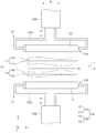
도 1은 본 발명의 일 실시예에 따른 전극 조립체 제조장치의 개념을 나타낸 블록도이고, 도 2는 본 발명의 일 실시예에 따른 전극 조립체 제조장치를 예시적으로 나타낸 측면도이며, 도 3은 본 발명의 일 실시예에 따른 전극 조립체 제조장치에서 라미네이션부를 나타낸 정면도이다.1 is a block diagram showing the concept of an electrode assembly manufacturing apparatus according to an embodiment of the present invention, Figure 2 is a side view showing an electrode assembly manufacturing apparatus according to an embodiment of the present invention by way of example, Figure 3 is the present invention It is a front view showing a lamination part in the electrode assembly manufacturing apparatus according to an embodiment of the present invention.
도 1 및 도 2를 참고하면, 본 발명의 일 실시예에 따른 전극 조립체 제조장치(100)는 전극(13) 또는 분리막(14) 중에서 어느 하나 이상의 두께를 측정하는 두께 측정부(110) 및 두께 측정부(110)를 통과하며 적층되는 전극(13) 및 분리막(14)을 한 쌍의 가압 롤부(120,130) 사이로 통과시키며 가압하여 접합시키는 라미네이션부(140)를 포함하여 전극 조립체(10)를 제조할 수 있다. 또한, 본 발명의 일 실시예에 따른 전극 조립체 제조장치(100)는 두께 측정부(110) 및 두께 측정부(110)를 통과하며 적층된 전극(13) 및 분리막(14)의 적층체(S)에 열을 가하는 히팅부(170)와, 한 쌍의 가압 롤부(120,130) 사이의 위치, 간격, 및 가압력을 조절하는 제어부(150)를 더 포함할 수 있다.1 and 2, the electrode
도 3을 참고하면, 전극 조립체(10)는 충방전이 가능한 발전소자로서, 전극(11) 및 분리막(14)이 교대로 적층되어 결집된 형태로 형성될 수 있다. 여기서, 전극(13)은 양극(12) 및 음극(11)으로 구성될 수 있다.Referring to FIG. 3, the
전극 조립체(10)는 양극(12), 분리막(14), 및 음극(11)이 교대로 적층되어 형성될 수 있다. The
양극(12)은 양극 집전체(12a) 및 양극 집전체(12a)에 도포된 양극 활물질(12b)을 포함할 수 있다. 양극 집전체(12a)는 예를 들어 알루미늄 재질의 포일(Foil)로 이루어질 수 있고, 양극 활물질(12b)은 예를 들어 리튬망간산화물, 리튬코발트산화물, 리튬니켈산화물, 리튬인산철, 또는 이들 중 1종 이상이 포함된 화합물 및 혼합물 등으로 이루어질 수 있다.The
음극(11)은 음극 집전체(11a) 및 음극 집전체(11a)에 도포된 음극 활물질(11b)을 포함할 수 있다. 음극 집전체(11a)는 예를 들어 구리(Cu) 또는 니켈(Ni) 재질로 이루어진 포일(foil)로 이루어질 수 있다. 음극 활물질(11b)은 예를 들어 인조흑연, 리튬금속, 리튬합금, 카본, 석유코크, 활성화 카본, 그래파이트, 실리콘 화합물, 주석 화합물, 티타늄 화합물 또는 이들의 합금으로 이루어질 수 있다. 이때, 음극 활물질은 예를 들어 비흑연계의 SiO(silica, 실리카) 또는 SiC(silicon carbide, 실리콘카바이드) 등이 더 포함되어 이루어질 수 있다.The
분리막(14)은 절연 재질 및 연성이 있는 재질로 이루어질 수 있다. 이때, 분리막(14)은 예를 들어 미다공성을 가지는 폴리에칠렌, 폴리프로필렌 등 폴리올레핀계 수지막으로 형성될 수 있다.The
도 1 및 도 2를 참고하면, 두께 측정부(110)는 전극(13) 또는 분리막(14) 중에서 어느 하나 이상의 두께를 측정할 수 있다.1 and 2, the
두께 측정부(110)는 접촉식 두께 측정 게이지로 이루어질 수 있다. 여기서, 접촉식 두께 측정 게이지는 예를 들어 다이알 게이지(Dial Gauge) 또는 초음파 두께 측정기로 이루어질 수 있다.(이때, 다이얼 게이지는 보다 구체적으로 예를 들어 미스토요 사의 다이알두께게이지7321 제품을 통해 측정할 수 있지만 본 발명이 여기에 반드시 한정되는 것은 아니다.)The
여기서, 두께 측정부(110)는 음극(11)의 두께를 측정하는 제1 두께 측정기(111)와, 분리막(14) 두께를 측정하는 제2 두께 측정기(112), 및 양극(12)의 두께를 측정하는 제3 두께 측정기(113)를 포함할 수 있다. 즉, 두께 측정부(110)에서 제1 두께 측정기(111), 제2 두께 측정기(112), 및 제3 두께 측정기(113)는 예를 들어 접촉식 두께 측정 게이지로 이루어질 수 있다.Here, the
히팅부(170)는 두께 측정부(110) 및 두께 측정부(110)를 통과하며 적층된 전극(13) 및 분리막(14)의 적층체(S)에 열을 가할 수 있다.The
또한, 히팅부(170)는 적층체(S)의 상측에 위치되는 상측 히팅부(171) 및 적층체(S)의 하측에 위치되는 하측 히팅부(172)를 포함할 수 있다. 이때, 상측 히팅부(171) 및 하측 히팅부(172)는 각각 히터(Heater)(미도시)에 의해 가열되며 상측 히팅부(171) 및 하측 히팅부(172) 사이를 통과하는 적층체(S)에 열을 전달하여 가열할 수 있다.In addition, the
한편, 히팅부(170)는 제어부(150)와 전기적으로 연결되어 제어부(150)에 의해 작동을 제어받을 수 있다.Meanwhile, the
도 1 내지 도 3을 참고하면, 라미네이션(lamination)부(140)는 두께 측정부(110)를 통과하며 적층되고, 히팅부(170)를 통과하며 가열된 전극(13) 및 분리막(14)을 위,아래로 배치되는 한 쌍의 가압 롤부(120,130) 사이로 통과시키며 압력을 가하여 전극(13) 및 분리막(14)을 접합시킬 수 있다. Referring to FIGS. 1 to 3, the
또한, 라미네이션부(140)는 두께 측정부(110)를 통해 측정된 전극(13) 또는 분리막(14) 중에서 어느 하나 이상의 두께에 따라 한 쌍의 가압 롤부(120,130)의 위치, 한 쌍의 가압 롤부(120,130) 사이의 간격, 및 한 쌍의 가압 롤부(120,130)의 가압력 중 적어도 어느 하나 이상을 조절하며 전극(13) 및 분리막(14) 사이를 접합시켜 전극 조립체(10)를 제조할 수 있다. 이때, 전극 조립체(10)는 일례로 전극(13) 및 분리막(14)의 적층체(S)를 커터(30)를 통해 일정 크기로 절단한 형태일 수 있다. 또한, 전극 조립체(10)는 다른 예로 커터(30)를 통해 일정 크기로 일정 크기로 절단된 단위셀이 분리막의 사이로 다수로 적층된 형태일 수 있다. In addition, the
그리고, 라미네이션부(140)는 제어부(150)를 더 포함하고, 제어부(150)에서 두께 측정부(110)를 통해 측정된 두께 측정값과 메모리((160)에 저장된 두께 표준값을 비교하여, 한 쌍의 가압 롤부(120,130) 사이의 위치, 간격, 및 가압력을 조절할 수 있다.Then, the
한 쌍의 가압 롤부(120,130)는 전극(13) 및 분리막(14)의 적층체(S)에서 상측 방향에 위치된 상측 가압 롤부(120) 및 하측 방향에 위치된 하측 가압 롤부(130)로 구성될 수 있다.The pair of
여기서, 상측 가압 롤부(120)는 상측 가압롤(121) 및 상측 가압롤(121)을 이동시키는 상측 이동부(122)를 포함할 수 있다. 또한, 하측 가압 롤부(130)는 하측 가압롤(131) 및 하측 가압롤(131)을 이동시키는 하측 이동부(132)를 포함할 수 있다.Here, the upper
상측 가압롤(121) 및 하측 가압롤(131)은 각각 원기둥 형태의 롤(Roll)로 이루어져 상측 가압롤(121) 및 하측 가압롤(131) 사이를 통과하는 전극(13) 및 분리막(14)의 양면을 가압할 수 있다.The
상측 이동부(122) 및 하측 이동부(132)는 예를 들어 액추에이터(actuator)이루어져 상측 가압롤(121) 및 하측 가압롤(131)을 상호 가까워지거나 멀어지는 방향으로 이동시킬 수 있다.The upper moving
여기서, 상측 이동부(122) 및 하측 이동부(132)는 각각 예를 들어 실린더(132b) 및 실린더(132b) 로부터 이동되는 이동대(132a)를 포함할 수 있다. 이때, 이동대(132a)는 상측 가압롤(121) 및 하측 가압롤(131)을 회전가능하게 지지하며 상측 가압롤(121) 및 하측 가압롤(131)을 이동시킬 수 있다.Here, the upper moving
그리고, 액추에이터는 구체적으로 예를 들어 공기압식, 유압식, 전기식, 또는 압식 액추에이터 중에서 어느 하나로 이루어질 수 있다.And, the actuator may be made of any one of, for example, pneumatic, hydraulic, electric, or pneumatic actuators.
상기와 같이 구성된 본 발명의 일 실시예에 따른 전극 조립체 제조장치(100)는 전극(13) 및 분리막(14)을 통과시키며 접합시키는 라미네이션부(140)로 투입 전에, 두께 측정부(110)에서 측정한 전극(13) 또는 분리막(14) 중에서 어느 하나 이상의 두께에 따라, 한 쌍의 가압 롤부(120,130)의 위치, 한 쌍의 가압 롤부(120,130) 사이의 간격, 및 한 쌍의 가압 롤부(120,130)의 가압력 중 적어도 어느 하나 이상을 제어부(150)에서 조절하며 전극(13) 및 분리막(14) 사이를 라미네이션시킬 수 있다. 따라서, 전극(13) 또는 분리막(14)의 공차를 반영하여 라미네이션시킴에 따라, 접착력 불균일을 완화시킬 수 있고, 공차 극복을 위해 과도한 압력을 가하지 않아도 되므로 분리막(14)의 변형을 최소화 할 수 있다. The electrode
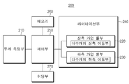
도 4는 본 발명의 다른 실시예에 따른 전극 조립체 제조장치의 개념을 나타낸 블록도이고, 도 5는 본 발명의 다른 실시예에 따른 전극 조립체 제조장치에서 두께 측정부를 나타낸 정면도이며, 도 6은 본 발명의 다른 실시예에 따른 전극 조립체 제조장치에서 라미네이션부를 나타낸 정면도이다.Figure 4 is a block diagram showing the concept of an electrode assembly manufacturing apparatus according to another embodiment of the present invention, Figure 5 is a front view showing a thickness measuring unit in the electrode assembly manufacturing apparatus according to another embodiment of the present invention, Figure 6 is the present It is a front view showing a lamination part in the electrode assembly manufacturing apparatus according to another embodiment of the present invention.
이하에서 본 발명의 다른 실시예에 따른 전극 조립체 제조장치를 설명하기로 한다.Hereinafter, an electrode assembly manufacturing apparatus according to another embodiment of the present invention will be described.
도 4 내지 도 6을 참고하면, 본 발명의 다른 실시예에 따른 전극 조립체 제조장치는 전극(13) 또는 분리막(14) 중에서 어느 하나 이상의 두께를 측정하는 두께 측정부(210) 및 두께 측정부(210)를 통과하며 적층되는 전극(13) 및 분리막(14)을 다수개의 가압롤(221a,221b,221c,231a,231b,231c)을 포함하는 한 쌍의 가압 롤부(220,230) 사이로 통과시키며 가압하여 접합시키는 라미네이션부(240)를 포함하여 전극 조립체를 제조할 수 있다. 또한, 본 발명의 다른 실시예에 따른 전극 조립체 제조장치는 두께 측정부(210) 및 두께 측정부(210)를 통과하며 적층된 전극(13) 및 분리막(14)의 적층체(S)에 열을 가하는 히팅부(270)와, 한 쌍의 가압 롤부(220,230) 사이의 위치, 간격, 및 가압력을 조절하는 제어부(250)를 더 포함할 수 있다.4 to 6, the electrode assembly manufacturing apparatus according to another embodiment of the present invention includes a
본 발명의 다른 실시예에 따른 전극 조립체 제조장치(200)는 전술한 일 실시예에 따른 전극 조립체 제조장치와 비교할 때, 두께 측정부(210)에서 전극(13) 또는 분리막(14)의 다수 곳의 두께를 측정하고, 한 쌍의 가압 롤부(220,230)가 각각 다수개의 가압롤(221a,221b,221c,231a,231b,231c)로 이루어진 차이가 있다.Electrode
따라서, 본 실시예는 일 실시예와 중복되는 내용은 간략히 기술하고, 차이점을 중심으로 기술하도록 한다.Therefore, in this embodiment, contents overlapping with one embodiment are briefly described, and the differences are mainly described.
보다 상세히, 본 발명의 다른 실시예에 따른 전극 조립체 제조장치에서 두께 측정부(210)는 전극(13) 또는 분리막(14) 중에서 어느 하나 이상의 두께를 측정할 수 있다.In more detail, in the electrode assembly manufacturing apparatus according to another embodiment of the present invention, the
두께 측정부(210)는 접촉식 두께 측정 게이지로 이루어질 수 있다. 여기서, 접촉식 두께 측정 게이지는 예를 들어 다이알 게이지(Dial Gauge) 또는 초음파 두께 측정기로 이루어질 수 있다. 이에 따라, 두께 측정부(210)는 마이크로 단위의 두께를 정밀하게 측정할 수 있다.The
여기서, 두께 측정부(210)는 일례로 단부가 측정부분과 접촉되는 다수개의 측정봉(212a,2212b,212c) 을 포함하는 두께 측정 게이지로 이루어질 수 있다. 이때, 다수개의 측정봉(212a,212b,212c) 은 전극(13) 및 분리막(14) 중에서 어느 하나 이상에서 폭방향(W)으로 다수 곳의 두께를 측정할 수 있다. 여기서, 다수개의 측정봉(212a,212b,212c)은 지지체(211)에 수직이동가능하게 지지될 수 있다. 이때, 폭방향은 예를 들어 도 5에 도시된 Y축 방향일 수 있다.Here, the
히팅부(270)는 두께 측정부(110) 및 두께 측정부(110)를 통과하며 적층된 전극(13) 및 분리막(14)의 적층체(S)에 열을 가할 수 있다.The
또한, 히팅부(270)는 히터로 가열되어 전극(13) 및 분리막(14)의 적층체(S)에 열을 전달하며 가열할 수 있다.In addition, the
한편, 히팅부(270)는 제어부(250)와 전기적으로 연결되어 제어부(250)에 의해 작동을 제어받을 수 있다.Meanwhile, the
라미네이션부(240)는 두께 측정부(210)를 통과하며 적층되고, 히팅부(270)를 통과하며 가열된 전극(13) 및 분리막(14)을 위,아래로 배치되는 한 쌍의 가압 롤부(220,230) 사이로 통과시키며 압력을 가하여 전극(13) 및 분리막(14)을 접합시킬 수 있다.The
또한, 라미네이션부(240)는 두께 측정부(210)를 통해 측정된 전극(13) 또는 분리막(14) 중에서 어느 하나 이상의 두께에 따라, 한 쌍의 가압 롤부(220,230)의 위치, 한 쌍의 가압 롤부(220,230) 사이의 간격, 및 한 쌍의 가압 롤부(220,230)의 가압력 중 적어도 어느 하나 이상을 조절하며 전극(13) 및 분리막(14) 사이를 접합시킬 수 있다.In addition, the
이때, 제어부(250)는 두께 측정부(210)를 통해 측정된 두께 측정값과 메모리(260)에 저장된 두께 표준값을 실시간으로 비교하여, 한 쌍의 가압 롤부(220,230)의 위치, 간격, 또는 가압력을 조절할 수 있다.In this case, the
한 쌍의 가압 롤부(220,230)는 각각 다수개의 가압롤(221a,221b,221c,231a,231b,231c)을 포함하고, 제어부(250)는 다수개의 가압롤(221a,221b,221c,231a,231b,231c)의 위치, 간격, 또는 가압력을 각 가압롤(221a,221b,221c,231a,231b,231c) 마다 개별적으로 조절할 수 있다.The pair of
또한, 한 쌍의 가압 롤부(220,230)의 다수개의 가압롤(221a,221b,221c,231a,231b,231c)은 폭방향(W)을 따라 배열될 수 있다. 이때, 제어부(250)는 두께 측정부(210)에서 측정된 다수 곳의 전극(13) 또는 분리막(14)의 두께에 따라 다수개의 가압롤(221a,221b,221c,231a,231b,231c)의 위치, 간격, 또는 가압력을 개별적으로 조절할 수 있다.Further, the plurality of
한편, 한 쌍의 가압 롤부(220,230)는 전극(13) 및 분리막(14)의 적층체(S)에서 상측 방향에 위치된 상측 가압 롤부(220) 및 하측 방향에 위치된 하측 가압 롤부(230) 로 구성될 수 있다.On the other hand, the pair of
상측 가압 롤부(220)는 다수개의 상측 가압롤(221a,221b,221c) 및 다수개의 상측 가압롤(221a,221b,221c)을 각각 이동시키는 다수개의 상측 이동부(222a,222b,222c)를 포함할 수 있다. 또한, 하측 가압 롤부(230)는 다수개의 하측 가압롤(231a,231b,231c) 및 다수개의 하측 가압롤(231a,231b,231c)을 각각 이동시키는 다수개의 하측 이동부(232a,232b,232c)를 포함할 수 있다.The upper
다수개의 상측 가압롤(221a,221b,221c) 및 다수개의 하측 가압롤(231a,231b,231c)은 각각 원기둥 형태의 롤로 이루어져 다수개의 상측 가압롤(221a,221b,221c) 및 다수개의 하측 가압롤(231a,231b,231c) 사이를 통과하는 전극(13) 및 분리막(14)의 양면을 각각 개별적으로 가압할 수 있다.The plurality of upper press rolls 221a, 221b, 221c and the plurality of lower press rolls 231a, 231b, 231c are each made of a cylindrical roll, and the plurality of upper press rolls 221a, 221b, 221c and a plurality of lower press rolls Both sides of the
다수개의 상측 이동부(222a,222b,222c) 및 다수개의 하측 이동부(232a,232b,232c)는 예를 들어 액추에이터(actuator)이루어져 다수개의 상측 가압롤(221a,221b,221c) 및 다수개의 하측 가압롤(231a,231b,231c)을 상호 가까워지거나 멀어지는 방향으로 이동시킬 수 있다. The plurality of upper moving parts (222a, 222b, 222c) and the plurality of lower moving parts (232a, 232b, 232c) are, for example, an actuator (actuator) is made of a plurality of upper pressure rolls (221a, 221b, 221c) and a plurality of lower The pressure rolls 231a, 231b, and 231c may be moved toward or away from each other.
그리고, 액추에이터는 구체적으로 예를 들어 공기압식, 유압식, 전기식, 또는 압식 액추에이터 중에서 어느 하나로 이루어질 수 있다.And, the actuator may be made of any one of, for example, pneumatic, hydraulic, electric, or pneumatic actuators.
상기와 같이 구성된 본 발명의 다른 실시예에 따른 전극 조립체 제조장치(200)는 두께 측정부(210)에서 전극(13) 또는 분리막(14)의 다수 곳의 두께를 측정하고, 전극(13) 또는 분리막(14)을 가압하여 접합시키는 라미네이션 부가 각각 다수개의 가압롤(221a,221b,221c,231a,231b,231c)을 포함하여 이루어진다. 이에 따라, 두께 측정부(210)에서 측정한 전극(13) 또는 분리막(14)의 다수 곳의 두께에 따라 제어부(250)에서 실시간 피드백(Feed back)하여 다수개의 가압롤(221a,221b,221c,231a,231b,231c)의 위치, 간격, 또는 가압력을 개별적으로 자동 제어하며 조절할 수 있다. 따라서, 전극(13) 또는 분리막(14)의 공차를 정밀하게 반영하여 라미네이션시킴에 따라, 접착력 불균일을 현저히 완화시킬 수 있다. 또한, 공차 극복을 위해 과도한 압력을 가하지 않아도 되므로 분리막의 변형을 현저히 최소화 할 수 있다. 아울러, 코로나 공정 같은 공정들이 불필요해져 공정이 단순화되고 제조 시간 및 제조 단가를 낮출 수 있다.The electrode
이하에서 본 발명의 일 실시예에 따른 전극 조립체 제조방법을 설명하기로 한다.Hereinafter, a method of manufacturing an electrode assembly according to an embodiment of the present invention will be described.
도 1 및 도 2를 참고하면, 본 발명의 일 실시예에 따른 전극 조립체 제조방법은 전극(13) 또는 분리막(14) 중에서 어느 하나 이상의 두께를 측정하는 두께 측정공정 및 전극(13) 및 분리막(14)을 적층시켜 위,아래로 배치되는 한 쌍의 가압 롤부(120,130) 사이로 통과시키며 가압하여 전극(13) 및 분리막(14)을 접합시키는 라미네이션 공정을 포함하여 전극 조립체(10)를 제조할 수 있다. 또한, 본 발명의 일 실시예에 따른 전극 조립체 제조방법은 두께측정공정을 통과하여 적층된 전극(13) 및 분리막(14)의 적층체(S)에 열을 가하는 히팅공정, 및 라미네이션 공정을 통해 접합된 전극(13) 및 분리막(14)의 불량 유무를 판별하는 검사공정을 더 포함할 수 있다.1 and 2, a method of manufacturing an electrode assembly according to an embodiment of the present invention includes a thickness measuring process and an
본 발명의 일 실시예에 따른 전극 조립체 제조방법은 전술한 일 실시예에 따른 전극 조립체 제조장치를 통해 전극 조립체를 제조하는 방법이다. 따라서, 본 실시예는 전술한 실시예와 중복되는 내용은 간략히 기술하고, 차이점을 중심으로 기술하도록 한다.An electrode assembly manufacturing method according to an embodiment of the present invention is a method of manufacturing an electrode assembly through the electrode assembly manufacturing apparatus according to the above-described embodiment. Therefore, in this embodiment, contents overlapping with the above-described embodiment will be briefly described, and the differences will be mainly described.
보다 상세히, 도 1 내지 도 3을 참고하면, 본 발명의 일 실시예에 따른 전극 조립체 제조방법에서 두께측정공정은 전극(13) 또는 분리막(14) 중에서 어느 하나 이상의 두께를 측정할 수 있다. More specifically, referring to FIGS. 1 to 3, in the electrode assembly manufacturing method according to an embodiment of the present invention, the thickness measurement process may measure any one or more thicknesses of the
또한, 두께측정공정은 예를 들어 접촉식 두께 측정 게이지로 이루어진 두께 측정부(110)를 통해 전극(13) 또는 분리막(14) 중에서 어느 하나 이상의 두께를 측정할 수 있다.In addition, the thickness measurement process may measure any one or more thicknesses of the
히팅공정은 두께측정공정을 통과하여 적층된 전극(13) 및 분리막(14)의 적층체(S)에 열을 가할 수 있다.In the heating process, heat may be applied to the stacked body S of the
또한, 히팅공정은 적층체(S)의 상측에 위치되는 상측 히팅부(171) 및 적층체(S)의 하측에 위치되는 하측 히팅부(172)를 포함하는 히팅부(170)를 통해 전극(13) 및 분리막(14)의 적층체(S)를 가열할 수 있다.In addition, the heating process is performed through the
라미네이션 공정은 전극(13) 및 분리막(14)을 적층시켜 위,아래로 배치되는 한 쌍의 가압 롤부(120,130) 사이로 통과시키며 가압하여 전극(13) 및 분리막(14)을 접합시킬 수 있다.In the lamination process, the
또한, 라미네이션 공정은 두께측정공정을 통해 측정된 전극(13) 또는 분리막(14) 중에서 어느 하나 이상의 두께에 따라, 한 쌍의 가압 롤부(120,130)의 위치, 한 쌍의 가압 롤부(120,130) 사이의 간격, 및 한 쌍의 가압 롤부(120,130)의 가압력 중 적어도 어느 하나 이상을 조절하며 전극(13) 및 분리막(14) 사이를 접합시킬 수 있다.In addition, the lamination process, depending on the thickness of any one or more of the
라미네이션 공정은 두께측정공정을 통해 측정된 두께 측정값과 메모리(160)에 저장된 두께 표준값을 제어부(150)에서 비교하여, 두께 측정값이 두께 표준값에 비해 작으면 한 쌍의 가압 롤부(120,130) 사이의 간격이 가까워지도록 이동시키고 작으면 한 쌍의 가압 롤부(120,130)가 가압하는 가압력을 낮추며, 두께 측정값이 두께 표준값에 비해 크면 한 쌍의 가압 롤부(120,130) 사이의 간격이 멀게 이동시키고, 한 쌍의 가압 롤부(120,130)가 가압하는 가압력을 높일 수 있다. The lamination process compares the thickness measurement value measured through the thickness measurement process with the thickness standard value stored in the
한편, 한 쌍의 가압 롤부(120,130)는 전극(13) 및 분리막(14)의 적층체(S)에서 상측 방향에 위치된 상측 가압 롤부(120) 및 하측 방향에 위치된 하측 가압 롤부(130)로 구성될 수 있다. 여기서, 상측 가압 롤부(120)는 상측 가압롤(121) 및 상측 가압롤(121)을 이동시키는 상측 이동부(122)를 포함할 수 있다. 또한, 하측 가압 롤부(130)는 하측 가압롤(131) 및 하측 가압롤(131)을 이동시키는 하측 이동부(132)를 포함할 수 있다.On the other hand, the pair of pressure rolls 120 and 130 are the upper
그리고, 라미네이션 공정에서 상측 가압롤(121) 및 하측 가압롤(131)은 각각 원기둥 형태의 롤로 이루어져 상측 가압롤(121) 및 하측 가압롤(131) 사이를 통과하는 전극(13) 및 분리막(14)의 양면을 가압하도록 할 수 있다. 그리고, 상측 이동부(122) 및 하측 이동부(132)는 예를 들어 액추에이터(actuator)이루어져 상측 가압롤(121) 및 하측 가압롤(131)을 상호 가까워지거나 멀어지는 방향으로 이동시킬 수 있다.And, in the lamination process, the
이때, 라미네이션 공정은 제어부(150)에서 상측 이동부(122) 및 하측 이동부(132)를 통해 상측 가압롤(121) 및 하측 가압롤(131)을 상,하 방향으로 이동시키며 상측 가압롤(121) 및 하측 가압롤(131) 사이의 위치, 간격, 및 가압력을 조절할 수 있다.At this time, the lamination process moves the
한편, 도 2 및 도 3을 참고하면, 전극(13) 및 분리막(14)이 두께측정공정을 거쳐 히팅 공정을 통해 라미네이션 공정으로 진행하는 진행 방향(G)은 예를 들어 X축 방향이고, 전극(13) 및 분리막(14)의 폭방향(W)은 Y축 방향이며, 전극(13) 및 분리막(14)의 두께 방향은 Z축 방향일 수 있다.On the other hand, referring to Figures 2 and 3, the
이하에서 본 발명의 다른 실시예에 따른 전극 조립체 제조방법을 설명하기로 한다.Hereinafter, a method of manufacturing an electrode assembly according to another embodiment of the present invention will be described.
도 4 내지 도 6을 참고하면, 본 발명의 다른 실시예에 따른 전극 조립체 제조방법은 전극(13) 또는 분리막(14) 중에서 어느 하나 이상의 두께를 측정하는 두께 측정공정 및 전극(13) 및 분리막(14)을 적층시켜 위,아래로 배치되는 한 쌍의 가압 롤부(220,230) 사이로 통과시키며 가압하여 전극(13) 및 분리막(14)을 접합시키는 라미네이션 공정을 포함하여 전극 조립체를 제조할 수 있다. 또한, 본 발명의 일 실시예에 따른 전극 조립체 제조방법은 두께측정공정을 통과하여 적층된 전극(13) 및 분리막(14)의 적층체(S)에 열을 가하는 히팅공정, 및 라미네이션 공정을 통해 접합된 전극(13) 및 분리막(14)의 불량 유무를 판별하는 검사공정을 더 포함할 수 있다.4 to 6, the electrode assembly manufacturing method according to another embodiment of the present invention includes a thickness measurement process and an
본 발명의 다른 실시예에 따른 전극 조립체 제조방법은 전술한 일 실시예에 따른 전극 조립체 제조방법과 비교할 때, 두께 측정공정에서 전극(13) 또는 분리막(14)의 다수 곳의 두께를 측정하고, 라미네이션 공정에서 전극(13) 및 분리막(14)을 한 쌍의 가압 롤부(220,230)가 다수개의 가압롤(221a,221b,221c,231a,231b,231c) 이루어져 개별적으로 가압하는 차이가 있다. 따라서, 본 실시예는 일 실시예와 중복되는 내용은 간략히 기술하고, 차이점을 중심으로 기술하도록 한다.The electrode assembly manufacturing method according to another embodiment of the present invention measures the thickness of a plurality of places of the
보다 상세히, 본 발명의 다른 실시예에 따른 전극 조립체 제조방법에서 두께측정공정은 전극(13) 또는 분리막(14) 중에서 어느 하나 이상의 두께를 측정할 수 있다. 이때, 두께측정공정은 전극(13) 및 분리막(14)의 진행 방향(G)에 대해 직각인 폭방향(W)으로 다수 곳의 두께를 측정할 수 있다. 여기서, 진행 방향(G)은 예를 들어 X축 방향이고, 폭방향(W)은 Y축 방향이며, 두께 방향은 Z축 방향일 수 있다.(도 2 참조)In more detail, in the electrode assembly manufacturing method according to another embodiment of the present invention, the thickness measurement process may measure any one or more thicknesses of the
또한, 두께측정공정은 예를 들어 접촉식 두께 측정 게이지로 이루어진 두께 측정부(210)를 통해 전극(13) 또는 분리막(14) 중에서 어느 하나 이상의 두께를 측정할 수 있다.In addition, the thickness measurement process may measure any one or more thicknesses of the
여기서, 두께측정공정은 일례로 단부가 측정부분과 접촉되는 다수개의 측정봉(212a,212b,212c) 을 포함하는 두께 측정 게이지로 이루어질 수 있다. 이때, 다수개의 측정봉(212a,212b,212c) 은 전극(13) 및 분리막(14) 중에서 어느 하나 이상에서 폭방향(W)으로 다수 곳의 두께를 측정할 수 있다.Here, the thickness measurement process may be made of, for example, a thickness measurement gauge including a plurality of
히팅공정은 두께측정공정을 통과하여 적층된 전극(13) 및 분리막(14)의 적층체(S)에 열을 가할 수 있다.In the heating process, heat may be applied to the stacked body S of the
또한, 히팅공정은 히터로 가열되는 히팅부(170)를 통해 전극(13) 및 분리막(14)의 적층체(S)를 가열할 수 있다.In addition, the heating process may heat the stacked body S of the
라미네이션 공정은 전극(13) 및 분리막(14)을 적층시켜 위,아래로 배치되는 한 쌍의 가압 롤부(220,230) 사이로 통과시키며 가압하여 전극(13) 및 분리막(14)을 접합시킬 수 있다.In the lamination process, the
또한, 라미네이션 공정은 두께측정공정을 통해 측정된 전극(13) 또는 분리막(14) 중에서 어느 하나 이상의 두께에 따라, 한 쌍의 가압 롤부(220,230)의 위치, 한 쌍의 가압 롤부(220,230) 사이의 간격, 및 한 쌍의 가압 롤부(220,230)의 가압력 중 적어도 어느 하나 이상을 조절하며 전극(13) 및 분리막(14) 사이를 접합시킬 수 있다.In addition, the lamination process is based on any one or more thicknesses of the
이때, 라미네이션 공정은 제어부(250)에서 두께측정공정을 통해 측정된 두께 측정값과 메모리(260)에 저장된 두께 표준값을 실시간으로 비교하여, 한 쌍의 가압 롤부(220,230)의 위치, 간격, 또는 가압력을 조절할 수 있다.At this time, the lamination process compares the thickness measurement value measured through the thickness measurement process in the
한편, 라미네이션 공정에서 한 쌍의 가압 롤부(220,230)는 각각 다수개의 가압롤(221a,221b,221c,231a,231b,231c)을 포함하여, 다수개의 가압롤(221a,221b,221c,231a,231b,231c)의 위치, 간격, 또는 가압력을 제어부(250)에서 각 가압롤(221a,221b,221c,231a,231b,231c) 마다 개별적으로 조절할 수 있다.Meanwhile, in the lamination process, the pair of press rolls 220 and 230 each include a plurality of press rolls 221a, 221b, 221c, 231a, 231b, 231c, and a plurality of press rolls 221a, 221b, 221c, 231a, 231b ,231c) may be individually adjusted for each
또한, 라미네이션 공정에서 한 쌍의 가압 롤부(220,230)의 다수개의 가압롤(221a,221b,221c,231a,231b,231c)은 폭방향(W)을 따라 배열될 수 있다. 이때, 라미네이션 공정은 두께 측정공정에서 측정된 다수 곳의 전극(13) 또는 분리막(14)의 두께에 따라 다수개의 가압롤(221a,221b,221c,231a,231b,231c)의 위치, 간격, 또는 가압력을 제어부(250)에서 개별적으로 조절할 수 있다.Further, in the lamination process, a plurality of pressure rolls 221a, 221b, 221c, 231a, 231b, 231c of the pair of
한편, 한 쌍의 가압 롤부(220,230)는 전극(13) 및 분리막(14)의 적층체(S)에서 상측 방향에 위치된 상측 가압 롤부(220) 및 하측 방향에 위치된 하측 가압 롤부(230)로 구성될 수 있다. 여기서, 상측 가압 롤부(220)는 다수개의 상측 가압롤(221a,221b,221c) 및 다수개의 상측 가압롤(221a,221b,221c)을 각각 이동시키는 다수개의 상측 이동부(222a,222b,222c)를 포함할 수 있다. 또한, 하측 가압 롤부(230)는 다수개의 하측 가압롤(231a,231b,231c) 및 다수개의 하측 가압롤(231a,231b,231c)을 각각 이동시키는 다수개의 하측 이동부(232a,232b,232c)를 포함할 수 있다.On the other hand, the pair of
이때, 라미네이션 공정은 제어부(250)에서 다수개의 상측 이동부(222a,222b,222c) 및 다수개의 하측 이동부(232a,232b,232c)를 통해 다수개의 상측 가압롤(221a,221b,221c) 및 다수개의 하측 가압롤(231a,231b,231c)을 개별적으로 상,하 방향으로 이동시키며 다수개의 상측 가압롤(221a,221b,221c) 및 다수개의 하측 가압롤(231a,231b,231c) 사이의 위치, 간격, 및 가압력을 개별적으로 조절할 수 있다.At this time, the lamination process may include a plurality of upper press rolls 221a, 221b, 221c and a plurality of upper moving
이상 본 발명을 구체적인 실시예를 통하여 상세히 설명하였으나, 이는 본 발명을 구체적으로 설명하기 위한 것으로, 본 발명에 따른 전극 조립체 제조장치 및 전극 조립체 제조방법은 이에 한정되지 않는다. 본 발명의 기술적 사상 내에서 당해 분야의 통상의 지식을 가진 자에 의해 다양한 실시가 가능하다고 할 것이다. The present invention has been described in detail through specific examples, but this is for specifically describing the present invention, and the electrode assembly manufacturing apparatus and electrode assembly manufacturing method according to the present invention are not limited thereto. It will be said that various implementations are possible by those skilled in the art within the technical spirit of the present invention.
또한, 발명의 구체적인 보호 범위는 첨부된 특허청구범위에 의하여 명확해질 것이다. In addition, the specific protection scope of the invention will be clarified by the appended claims.
10: 전극 조립체
11: 음극
11a: 음극 집전체
11b: 음극 활물질
12: 양극
12a: 양극 집전체
12b: 양극 활물질
13: 전극
14: 분리막
30: 커터
100,200: 전극 조립체 제조장치
110,210: 두께 측정부
120,220: 상측 가압 롤부
121: 상측 가압롤
122: 상측 이동부
122a: 이동대
122b: 실링더
130,230: 하측 가압 롤부
131: 하측 가압롤
132: 하측 이동부
132a: 이동대
132b: 실린더
140,240: 라미네이션부
150,250: 제어부
160,260: 메모리
170,270: 히팅부
171: 상측 히팅부
172: 하측 히팅부
211: 지지체
S: 적층체10: electrode assembly
11: Cathode
11a: cathode current collector
11b: negative electrode active material
12: anode
12a: anode current collector
12b: positive electrode active material
13: electrode
14: separator
30: cutter
100,200: electrode assembly manufacturing apparatus
110,210: thickness measurement unit
120,220: upper pressure roll part
121: upper pressure roll
122: upper moving part
122a: Mobile table
122b: Sealer
130, 230: lower pressure roll portion
131: lower pressure roll
132: lower moving part
132a: Mobile table
132b: cylinder
140,240: lamination
150,250: control unit
160,260: memory
170,270: heating part
171: upper heating part
172: lower heating part
211: support
S: laminate
Claims (14)
상기 두께 측정부를 통과하며 적층되는 상기 전극 및 상기 분리막을 위,아래로 배치되는 한 쌍의 가압 롤부 사이로 통과시키며 가압하여 상기 전극 및 상기 분리막을 접합시키는 라미네이션부를 포함하고,
상기 라미네이션부는 상기 두께 측정부를 통해 측정된 상기 전극 또는 상기 분리막 중에서 어느 하나 이상의 두께에 따라, 상기 한 쌍의 가압 롤부의 위치, 상기 한 쌍의 가압 롤부 사이의 간격, 및 상기 한 쌍의 가압 롤부의 가압력 중 적어도 어느 하나 이상을 조절하며 상기 전극 및 상기 분리막 사이를 접합시키는 전극 조립체 제조장치.A thickness measuring unit for measuring any one or more thickness of the electrode or separator; And
And a lamination unit for passing the electrode stacked while passing through the thickness measurement unit and the separation membrane through a pair of pressure roll units disposed above and below and bonding the electrode and the separation membrane by pressing.
The lamination portion according to the thickness of any one or more of the electrode or the separation membrane measured through the thickness measuring portion, the position of the pair of press roll portions, the gap between the pair of press roll portions, and the pair of press roll portions Electrode assembly manufacturing apparatus for controlling at least one or more of the pressing force and bonding between the electrode and the separator.
두께 측정부를 통과하며 적층된 상기 전극 및 상기 분리막의 적층체를 가압하기 전 열을 가하는 히팅부를 더 포함하는 전극 조립체 제조장치.The method according to claim 1,
An electrode assembly manufacturing apparatus further comprising a heating unit that applies heat before pressing the stacked layers of the electrode and the separator passing through the thickness measurement unit.
상기 라미네이션부는 제어부를 더 포함하고,
상기 제어부는 상기 두께 측정부를 통해 측정된 두께 측정값과 메모리에 저장된 두께 표준값을 비교하여, 상기 한 쌍의 가압 롤부의 위치, 간격, 또는 가압력을 조절하는 전극 조립체 제조장치. The method according to claim 2,
The lamination unit further includes a control unit,
The control unit compares the thickness measurement value measured through the thickness measurement unit and the thickness standard value stored in the memory, and adjusts the position, spacing, or pressing force of the pair of pressure roll units.
상기 한 쌍의 가압 롤부는 각각 다수개의 가압롤을 포함하고,
상기 제어부는 상기 다수개의 가압롤의 위치, 간격, 또는 가압력을 각 가압롤 마다 개별적으로 조절하는 전극 조립체 제조장치.The method according to claim 3,
Each of the pair of press rolls includes a plurality of press rolls,
The control unit is an electrode assembly manufacturing apparatus for individually adjusting the position, spacing, or pressing force of the plurality of pressure rolls for each pressure roll.
상기 두께 측정부는 상기 전극 및 상기 분리막의 진행 방향에 대해 직각인 폭방향으로 다수 곳의 두께를 측정하고,
상기 한 쌍의 가압 롤부의 다수개의 가압롤은 상기 폭방향을 따라 배열되며,
상기 제어부는 상기 두께 측정부에서 측정된 다수 곳의 상기 전극 또는 상기 분리막의 두께에 따라 상기 다수개의 가압롤의 위치, 간격, 또는 가압력을 개별적으로 조절하는 전극 조립체 제조장치.The method according to claim 4,
The thickness measuring unit measures the thickness of a plurality of places in the width direction perpendicular to the traveling direction of the electrode and the separator,
A plurality of pressure rolls of the pair of pressure rolls are arranged along the width direction,
The control unit is an electrode assembly manufacturing apparatus for individually adjusting the position, spacing, or pressing force of the plurality of pressure rolls according to the thickness of the electrode or the separation membrane in a plurality of locations measured by the thickness measurement unit.
상기 두께 측정부는
단부가 측정부분과 접촉되는 다수개의 측정봉을 포함하는 접촉식 두께 측정 게이지로 이루어지는 전극 조립체 제조장치.The method according to claim 5,
The thickness measurement unit
An electrode assembly manufacturing apparatus comprising a contact-type thickness measuring gauge including a plurality of measuring rods whose ends are in contact with a measuring portion.
상기 다수개의 측정봉은
상기 전극 및 상기 분리막 중 어느 하나 이상에서 폭방향으로 다수 곳의 두께를 측정하는 전극 조립체 제조장치.The method according to claim 6,
The plurality of measuring rods
Electrode assembly manufacturing apparatus for measuring the thickness of a plurality of places in the width direction from any one or more of the electrode and the separator.
상기 전극 및 상기 분리막을 적층시켜 위,아래로 배치되는 한 쌍의 가압 롤부 사이로 통과시키며 가압하여 상기 전극 및 상기 분리막을 접합시키는 라미네이션 공정을 포함하고,
상기 라미네이션 공정은 상기 두께측정공정을 통해 측정된 상기 전극 또는 상기 분리막 중에서 어느 하나 이상의 두께에 따라, 상기 한 쌍의 가압 롤부의 위치, 상기 한 쌍의 가압 롤부 사이의 간격, 및 상기 한 쌍의 가압 롤부의 가압력 중 적어도 어느 하나 이상을 조절하며 상기 전극 및 상기 분리막 사이를 접합시키는 전극 조립체 제조방법. A thickness measurement process for measuring any one or more thicknesses of electrodes or separators; And
The lamination process of laminating the electrode and the separator to pass through between a pair of press roll parts disposed above and below and pressing to bond the electrode and the separator,
The lamination process may include a position of the pair of press roll parts, a gap between the pair of press roll parts, and the pair of pressurizations according to at least one thickness of the electrode or the separator measured through the thickness measurement process. A method of manufacturing an electrode assembly for controlling at least one or more of the pressing force of a roll part and bonding the electrode and the separator.
상기 두께측정공정을 통과하여 적층된 상기 전극 및 상기 분리막의 적층체에 열을 가하는 히팅공정을 더 포함하는 전극 조립체 제조방법.The method according to claim 8,
The electrode assembly manufacturing method further comprises a heating step of applying heat to the stack of the electrode and the separator laminated through the thickness measurement process.
상기 라미네이션 공정은
상기 두께측정공정을 통해 측정된 두께 측정값과 메모리에 저장된 두께 표준값을 제어부에서 비교하여, 상기 한 쌍의 가압 롤부 사이의 위치, 간격, 또는 가압력을 조절하는 전극 조립체 제조방법. The method according to claim 9,
The lamination process
A method of manufacturing an electrode assembly for comparing a thickness measurement value measured through the thickness measurement process and a thickness standard value stored in the memory by a control unit to adjust the position, spacing, or pressing force between the pair of pressure roll units.
상기 라미네이션 공정은
상기 두께측정공정을 통해 측정된 두께 측정값과 상기 메모리에 저장된 두께 표준값을 제어부에서 비교하여,
상기 두께 측정값이 상기 두께 표준값에 비해 작으면 상기 한 쌍의 가압 롤부 사이의 간격이 가까워지도록 이동시키고 작으면 상기 한 쌍의 가압 롤부가 가압하는 가압력을 낮추며,
상기 두께 측정값이 상기 두께 표준값에 비해 크면 상기 한 쌍의 가압 롤부 사이의 간격이 멀게 이동시키고, 상기 한 쌍의 가압 롤부가 가압하는 가압력을 높이는 전극 조립체 제조방법. The method according to claim 10,
The lamination process
The control unit compares the thickness measurement value measured through the thickness measurement process with the thickness standard value stored in the memory,
If the thickness measurement value is smaller than the thickness standard value, the gap between the pair of press roll portions is moved closer, and if it is smaller, the pressing force pressed by the pair of press roll portions is lowered.
When the thickness measurement value is larger than the thickness standard value, the gap between the pair of press roll portions moves away, and the electrode assembly manufacturing method increases the pressing force of the pair of press roll portions.
상기 라미네이션 공정에서,
상기 한 쌍의 가압 롤부는 각각 다수개의 가압롤을 포함하여,
상기 제어부에서 상기 다수개의 가압롤 사이의 위치, 간격, 또는 가압력을 가압롤 마다 개별적으로 조절하는 전극 조립체 제조방법.The method according to claim 10,
In the lamination process,
Each of the pair of press rolls includes a plurality of press rolls,
A method of manufacturing an electrode assembly in which the control unit individually adjusts the position, spacing, or pressing force between the plurality of pressure rolls for each pressure roll.
상기 두께측정공정은 상기 전극 및 상기 분리막의 진행 방향에 대해 직각인 폭방향으로 다수 곳의 두께를 측정하고,
상기 라미네이션 공정에서 상기 다수개의 가압롤이 상기 폭방향을 따라 배열되어, 상기 두께측정공정에서 측정된 다수 곳의 상기 전극 또는 상기 분리막의 두께에 따라 상기 다수개의 가압롤 사이의 위치, 간격, 또는 가압력을 상기 제어부에서 개별적으로 조절하는 전극 조립체 제조방법.The method according to claim 12,
The thickness measurement process measures the thickness of a plurality of places in the width direction perpendicular to the traveling direction of the electrode and the separator,
In the lamination process, the plurality of pressure rolls are arranged along the width direction, and the position, spacing, or pressing force between the plurality of pressure rolls according to the thickness of the electrode or the separator in a plurality of places measured in the thickness measurement process. Electrode assembly manufacturing method for individually adjusting the control unit.
상기 라미네이션 공정을 거친 후,
상기 라미네이션 공정을 통해 접합된 상기 전극 및 상기 분리막의 전체 두께를 측정하여 불량 유무를 판별하는 검사공정을 더 포함하는 전극 조립체 제조방법.
The method according to claim 9,
After going through the lamination process,
The electrode assembly manufacturing method further comprises an inspection process for determining whether a defect is present by measuring the total thickness of the electrode and the separator bonded through the lamination process.
Priority Applications (1)
| Application Number | Priority Date | Filing Date | Title |
|---|---|---|---|
| KR1020180153606A KR20200066901A (en) | 2018-12-03 | 2018-12-03 | Manufacturing equipment and manufacturing method of electrode assembly |
Applications Claiming Priority (1)
| Application Number | Priority Date | Filing Date | Title |
|---|---|---|---|
| KR1020180153606A KR20200066901A (en) | 2018-12-03 | 2018-12-03 | Manufacturing equipment and manufacturing method of electrode assembly |
Publications (1)
| Publication Number | Publication Date |
|---|---|
| KR20200066901A true KR20200066901A (en) | 2020-06-11 |
Family
ID=71070480
Family Applications (1)
| Application Number | Title | Priority Date | Filing Date |
|---|---|---|---|
| KR1020180153606A KR20200066901A (en) | 2018-12-03 | 2018-12-03 | Manufacturing equipment and manufacturing method of electrode assembly |
Country Status (1)
| Country | Link |
|---|---|
| KR (1) | KR20200066901A (en) |
Cited By (7)
| Publication number | Priority date | Publication date | Assignee | Title |
|---|---|---|---|---|
| WO2022019504A1 (en) * | 2020-07-20 | 2022-01-27 | 주식회사 엘지에너지솔루션 | Ultrasonic welding device and welding method for secondary battery |
| WO2022139211A1 (en) * | 2020-12-23 | 2022-06-30 | 주식회사 엘지에너지솔루션 | Method and apparatus for manufacturing unit cell |
| KR20220109202A (en) | 2021-01-28 | 2022-08-04 | 주식회사 엘지에너지솔루션 | Separator Adhesive Device |
| WO2022169237A1 (en) * | 2021-02-05 | 2022-08-11 | 주식회사 엘지에너지솔루션 | Lamination device comprising pressure roll capable of adjusting pressing force and electrode assembly manufactured by using same |
| WO2022169238A1 (en) * | 2021-02-04 | 2022-08-11 | 주식회사 엘지에너지솔루션 | Lamination device and method for discharging defective electrode cell assembly of lamination device |
| KR20220122868A (en) * | 2021-02-26 | 2022-09-05 | (주)피엔티 | Apparatus and method for fabricating all solid state secondary battery |
| CN116774665A (en) * | 2023-08-18 | 2023-09-19 | 湖南隆深氢能科技有限公司 | Intelligent control method and system for roll-to-roll laminating production line |
Citations (1)
| Publication number | Priority date | Publication date | Assignee | Title |
|---|---|---|---|---|
| KR20140015647A (en) | 2012-06-22 | 2014-02-07 | 주식회사 엘지화학 | Electrode assembly, manufacture thereof, and secondary batteries including same |
-
2018
- 2018-12-03 KR KR1020180153606A patent/KR20200066901A/en not_active Application Discontinuation
Patent Citations (1)
| Publication number | Priority date | Publication date | Assignee | Title |
|---|---|---|---|---|
| KR20140015647A (en) | 2012-06-22 | 2014-02-07 | 주식회사 엘지화학 | Electrode assembly, manufacture thereof, and secondary batteries including same |
Cited By (9)
| Publication number | Priority date | Publication date | Assignee | Title |
|---|---|---|---|---|
| WO2022019504A1 (en) * | 2020-07-20 | 2022-01-27 | 주식회사 엘지에너지솔루션 | Ultrasonic welding device and welding method for secondary battery |
| WO2022139211A1 (en) * | 2020-12-23 | 2022-06-30 | 주식회사 엘지에너지솔루션 | Method and apparatus for manufacturing unit cell |
| KR20220109202A (en) | 2021-01-28 | 2022-08-04 | 주식회사 엘지에너지솔루션 | Separator Adhesive Device |
| WO2022164257A1 (en) | 2021-01-28 | 2022-08-04 | 주식회사 엘지에너지솔루션 | Separator bonding device |
| WO2022169238A1 (en) * | 2021-02-04 | 2022-08-11 | 주식회사 엘지에너지솔루션 | Lamination device and method for discharging defective electrode cell assembly of lamination device |
| WO2022169237A1 (en) * | 2021-02-05 | 2022-08-11 | 주식회사 엘지에너지솔루션 | Lamination device comprising pressure roll capable of adjusting pressing force and electrode assembly manufactured by using same |
| KR20220122868A (en) * | 2021-02-26 | 2022-09-05 | (주)피엔티 | Apparatus and method for fabricating all solid state secondary battery |
| CN116774665A (en) * | 2023-08-18 | 2023-09-19 | 湖南隆深氢能科技有限公司 | Intelligent control method and system for roll-to-roll laminating production line |
| CN116774665B (en) * | 2023-08-18 | 2023-11-14 | 湖南隆深氢能科技有限公司 | Intelligent control method and system for roll-to-roll laminating production line |
Similar Documents
| Publication | Publication Date | Title |
|---|---|---|
| KR20200066901A (en) | Manufacturing equipment and manufacturing method of electrode assembly | |
| CN103298572B (en) | Continuous prismatic cell stacking system and method | |
| US9768440B2 (en) | Method of manufacturing electrode assembly | |
| TWI501443B (en) | Method of manufacturing electrode assembly | |
| TWI517476B (en) | Electrode assembly, fabricating method of electrode assembly and electrochemical cell containing the electrode assembly | |
| KR20210058170A (en) | Electrode assembly manufacturing method and electrode assembly manufactured manufacturing device | |
| KR101664945B1 (en) | Method for manufacturing electrode assembly and electrode assembly manufactured using the same | |
| KR20200125024A (en) | Electrode assembly manufacturing equipment, electrode assembly manufactured from thereof and rechargeable battery | |
| US11749841B2 (en) | Method for manufacturing electrode assembly and method for manufacturing secondary battery | |
| CN115461901A (en) | Apparatus and method for manufacturing unit cell | |
| US20220069276A1 (en) | Apparatus for manufacturing electrode assembly, electrode assembly manufactured therethrough, and secondary battery | |
| KR20200107280A (en) | Method for Optimizing Ultrasonic Welding Process of Lithium Secondary Battery and Apparatus Thereof | |
| KR20150056932A (en) | Apparatus for Attaching the Adhesion Member for Fixing Battery Assembly | |
| EP4131534A1 (en) | Lamination device comprising pressure roll capable of adjusting pressing force and electrode assembly manufactured by using same | |
| KR20200126767A (en) | Electrode assembly manufacturing method, electrode assembly manufactured from thereof and rechargeable battery | |
| US20200083555A1 (en) | Secondary battery, and apparatus and method for manufacturing the same | |
| KR102265236B1 (en) | Device for Manufacturing of Battery Cell Comprising Sealing Tool of Induction Heating Type | |
| EP3866242A1 (en) | Electrode assembly manufacturing apparatus and electrode assembly manufacturing method | |
| KR20220025500A (en) | Device of manufacturing a secondary battery | |
| KR20210078380A (en) | Manufacturing method of single cell by alternating supply of electrode | |
| KR20230046461A (en) | Electrode assembly manufacturing method and manufacturing device | |
| JP2023537926A (en) | pouch sealing device | |
| KR20220136086A (en) | Mono Cell Manufacturing Device Equipped With Gloss Meter And Manufacturing Method Using It | |
| KR20230123839A (en) | Secondary battery manufacturing method and secondary battery manufacturing apparatus used therefor | |
| JP2024509202A (en) | Electrode assembly and battery cell containing same |
Legal Events
| Date | Code | Title | Description |
|---|---|---|---|
| N231 | Notification of change of applicant | ||
| E902 | Notification of reason for refusal |