KR20200065010A - Lithium-ion battery with modular busbar assembly - Google Patents
Lithium-ion battery with modular busbar assembly Download PDFInfo
- Publication number
- KR20200065010A KR20200065010A KR1020207011479A KR20207011479A KR20200065010A KR 20200065010 A KR20200065010 A KR 20200065010A KR 1020207011479 A KR1020207011479 A KR 1020207011479A KR 20207011479 A KR20207011479 A KR 20207011479A KR 20200065010 A KR20200065010 A KR 20200065010A
- Authority
- KR
- South Korea
- Prior art keywords
- lithium ion
- ion battery
- busbar
- electrochemical
- cathode
- Prior art date
Links
Images
Classifications
-
- H—ELECTRICITY
- H01—ELECTRIC ELEMENTS
- H01M—PROCESSES OR MEANS, e.g. BATTERIES, FOR THE DIRECT CONVERSION OF CHEMICAL ENERGY INTO ELECTRICAL ENERGY
- H01M50/00—Constructional details or processes of manufacture of the non-active parts of electrochemical cells other than fuel cells, e.g. hybrid cells
- H01M50/50—Current conducting connections for cells or batteries
- H01M50/502—Interconnectors for connecting terminals of adjacent batteries; Interconnectors for connecting cells outside a battery casing
-
- H01M2/206—
-
- H—ELECTRICITY
- H01—ELECTRIC ELEMENTS
- H01M—PROCESSES OR MEANS, e.g. BATTERIES, FOR THE DIRECT CONVERSION OF CHEMICAL ENERGY INTO ELECTRICAL ENERGY
- H01M10/00—Secondary cells; Manufacture thereof
- H01M10/05—Accumulators with non-aqueous electrolyte
- H01M10/052—Li-accumulators
- H01M10/0525—Rocking-chair batteries, i.e. batteries with lithium insertion or intercalation in both electrodes; Lithium-ion batteries
-
- H—ELECTRICITY
- H01—ELECTRIC ELEMENTS
- H01M—PROCESSES OR MEANS, e.g. BATTERIES, FOR THE DIRECT CONVERSION OF CHEMICAL ENERGY INTO ELECTRICAL ENERGY
- H01M10/00—Secondary cells; Manufacture thereof
- H01M10/60—Heating or cooling; Temperature control
- H01M10/65—Means for temperature control structurally associated with the cells
- H01M10/653—Means for temperature control structurally associated with the cells characterised by electrically insulating or thermally conductive materials
-
- H01M2/0237—
-
- H01M2/105—
-
- H01M2/1077—
-
- H01M2/1094—
-
- H01M2/127—
-
- H01M2/204—
-
- H01M2/345—
-
- H01M2/365—
-
- H—ELECTRICITY
- H01—ELECTRIC ELEMENTS
- H01M—PROCESSES OR MEANS, e.g. BATTERIES, FOR THE DIRECT CONVERSION OF CHEMICAL ENERGY INTO ELECTRICAL ENERGY
- H01M50/00—Constructional details or processes of manufacture of the non-active parts of electrochemical cells other than fuel cells, e.g. hybrid cells
- H01M50/10—Primary casings, jackets or wrappings of a single cell or a single battery
- H01M50/102—Primary casings, jackets or wrappings of a single cell or a single battery characterised by their shape or physical structure
- H01M50/107—Primary casings, jackets or wrappings of a single cell or a single battery characterised by their shape or physical structure having curved cross-section, e.g. round or elliptic
-
- H—ELECTRICITY
- H01—ELECTRIC ELEMENTS
- H01M—PROCESSES OR MEANS, e.g. BATTERIES, FOR THE DIRECT CONVERSION OF CHEMICAL ENERGY INTO ELECTRICAL ENERGY
- H01M50/00—Constructional details or processes of manufacture of the non-active parts of electrochemical cells other than fuel cells, e.g. hybrid cells
- H01M50/10—Primary casings, jackets or wrappings of a single cell or a single battery
- H01M50/147—Lids or covers
- H01M50/148—Lids or covers characterised by their shape
- H01M50/152—Lids or covers characterised by their shape for cells having curved cross-section, e.g. round or elliptic
-
- H—ELECTRICITY
- H01—ELECTRIC ELEMENTS
- H01M—PROCESSES OR MEANS, e.g. BATTERIES, FOR THE DIRECT CONVERSION OF CHEMICAL ENERGY INTO ELECTRICAL ENERGY
- H01M50/00—Constructional details or processes of manufacture of the non-active parts of electrochemical cells other than fuel cells, e.g. hybrid cells
- H01M50/20—Mountings; Secondary casings or frames; Racks, modules or packs; Suspension devices; Shock absorbers; Transport or carrying devices; Holders
- H01M50/204—Racks, modules or packs for multiple batteries or multiple cells
- H01M50/207—Racks, modules or packs for multiple batteries or multiple cells characterised by their shape
- H01M50/213—Racks, modules or packs for multiple batteries or multiple cells characterised by their shape adapted for cells having curved cross-section, e.g. round or elliptic
-
- H—ELECTRICITY
- H01—ELECTRIC ELEMENTS
- H01M—PROCESSES OR MEANS, e.g. BATTERIES, FOR THE DIRECT CONVERSION OF CHEMICAL ENERGY INTO ELECTRICAL ENERGY
- H01M50/00—Constructional details or processes of manufacture of the non-active parts of electrochemical cells other than fuel cells, e.g. hybrid cells
- H01M50/20—Mountings; Secondary casings or frames; Racks, modules or packs; Suspension devices; Shock absorbers; Transport or carrying devices; Holders
- H01M50/233—Mountings; Secondary casings or frames; Racks, modules or packs; Suspension devices; Shock absorbers; Transport or carrying devices; Holders characterised by physical properties of casings or racks, e.g. dimensions
- H01M50/24—Mountings; Secondary casings or frames; Racks, modules or packs; Suspension devices; Shock absorbers; Transport or carrying devices; Holders characterised by physical properties of casings or racks, e.g. dimensions adapted for protecting batteries from their environment, e.g. from corrosion
-
- H—ELECTRICITY
- H01—ELECTRIC ELEMENTS
- H01M—PROCESSES OR MEANS, e.g. BATTERIES, FOR THE DIRECT CONVERSION OF CHEMICAL ENERGY INTO ELECTRICAL ENERGY
- H01M50/00—Constructional details or processes of manufacture of the non-active parts of electrochemical cells other than fuel cells, e.g. hybrid cells
- H01M50/20—Mountings; Secondary casings or frames; Racks, modules or packs; Suspension devices; Shock absorbers; Transport or carrying devices; Holders
- H01M50/271—Lids or covers for the racks or secondary casings
-
- H—ELECTRICITY
- H01—ELECTRIC ELEMENTS
- H01M—PROCESSES OR MEANS, e.g. BATTERIES, FOR THE DIRECT CONVERSION OF CHEMICAL ENERGY INTO ELECTRICAL ENERGY
- H01M50/00—Constructional details or processes of manufacture of the non-active parts of electrochemical cells other than fuel cells, e.g. hybrid cells
- H01M50/30—Arrangements for facilitating escape of gases
- H01M50/383—Flame arresting or ignition-preventing means
-
- H—ELECTRICITY
- H01—ELECTRIC ELEMENTS
- H01M—PROCESSES OR MEANS, e.g. BATTERIES, FOR THE DIRECT CONVERSION OF CHEMICAL ENERGY INTO ELECTRICAL ENERGY
- H01M50/00—Constructional details or processes of manufacture of the non-active parts of electrochemical cells other than fuel cells, e.g. hybrid cells
- H01M50/30—Arrangements for facilitating escape of gases
- H01M50/394—Gas-pervious parts or elements
-
- H—ELECTRICITY
- H01—ELECTRIC ELEMENTS
- H01M—PROCESSES OR MEANS, e.g. BATTERIES, FOR THE DIRECT CONVERSION OF CHEMICAL ENERGY INTO ELECTRICAL ENERGY
- H01M50/00—Constructional details or processes of manufacture of the non-active parts of electrochemical cells other than fuel cells, e.g. hybrid cells
- H01M50/50—Current conducting connections for cells or batteries
- H01M50/502—Interconnectors for connecting terminals of adjacent batteries; Interconnectors for connecting cells outside a battery casing
- H01M50/505—Interconnectors for connecting terminals of adjacent batteries; Interconnectors for connecting cells outside a battery casing comprising a single busbar
-
- H—ELECTRICITY
- H01—ELECTRIC ELEMENTS
- H01M—PROCESSES OR MEANS, e.g. BATTERIES, FOR THE DIRECT CONVERSION OF CHEMICAL ENERGY INTO ELECTRICAL ENERGY
- H01M50/00—Constructional details or processes of manufacture of the non-active parts of electrochemical cells other than fuel cells, e.g. hybrid cells
- H01M50/50—Current conducting connections for cells or batteries
- H01M50/502—Interconnectors for connecting terminals of adjacent batteries; Interconnectors for connecting cells outside a battery casing
- H01M50/514—Methods for interconnecting adjacent batteries or cells
- H01M50/516—Methods for interconnecting adjacent batteries or cells by welding, soldering or brazing
-
- H—ELECTRICITY
- H01—ELECTRIC ELEMENTS
- H01M—PROCESSES OR MEANS, e.g. BATTERIES, FOR THE DIRECT CONVERSION OF CHEMICAL ENERGY INTO ELECTRICAL ENERGY
- H01M50/00—Constructional details or processes of manufacture of the non-active parts of electrochemical cells other than fuel cells, e.g. hybrid cells
- H01M50/50—Current conducting connections for cells or batteries
- H01M50/502—Interconnectors for connecting terminals of adjacent batteries; Interconnectors for connecting cells outside a battery casing
- H01M50/521—Interconnectors for connecting terminals of adjacent batteries; Interconnectors for connecting cells outside a battery casing characterised by the material
- H01M50/522—Inorganic material
-
- H—ELECTRICITY
- H01—ELECTRIC ELEMENTS
- H01M—PROCESSES OR MEANS, e.g. BATTERIES, FOR THE DIRECT CONVERSION OF CHEMICAL ENERGY INTO ELECTRICAL ENERGY
- H01M50/00—Constructional details or processes of manufacture of the non-active parts of electrochemical cells other than fuel cells, e.g. hybrid cells
- H01M50/50—Current conducting connections for cells or batteries
- H01M50/502—Interconnectors for connecting terminals of adjacent batteries; Interconnectors for connecting cells outside a battery casing
- H01M50/521—Interconnectors for connecting terminals of adjacent batteries; Interconnectors for connecting cells outside a battery casing characterised by the material
- H01M50/524—Organic material
-
- H—ELECTRICITY
- H01—ELECTRIC ELEMENTS
- H01M—PROCESSES OR MEANS, e.g. BATTERIES, FOR THE DIRECT CONVERSION OF CHEMICAL ENERGY INTO ELECTRICAL ENERGY
- H01M50/00—Constructional details or processes of manufacture of the non-active parts of electrochemical cells other than fuel cells, e.g. hybrid cells
- H01M50/50—Current conducting connections for cells or batteries
- H01M50/502—Interconnectors for connecting terminals of adjacent batteries; Interconnectors for connecting cells outside a battery casing
- H01M50/521—Interconnectors for connecting terminals of adjacent batteries; Interconnectors for connecting cells outside a battery casing characterised by the material
- H01M50/526—Interconnectors for connecting terminals of adjacent batteries; Interconnectors for connecting cells outside a battery casing characterised by the material having a layered structure
-
- H—ELECTRICITY
- H01—ELECTRIC ELEMENTS
- H01M—PROCESSES OR MEANS, e.g. BATTERIES, FOR THE DIRECT CONVERSION OF CHEMICAL ENERGY INTO ELECTRICAL ENERGY
- H01M50/00—Constructional details or processes of manufacture of the non-active parts of electrochemical cells other than fuel cells, e.g. hybrid cells
- H01M50/50—Current conducting connections for cells or batteries
- H01M50/572—Means for preventing undesired use or discharge
- H01M50/574—Devices or arrangements for the interruption of current
- H01M50/578—Devices or arrangements for the interruption of current in response to pressure
-
- H—ELECTRICITY
- H01—ELECTRIC ELEMENTS
- H01M—PROCESSES OR MEANS, e.g. BATTERIES, FOR THE DIRECT CONVERSION OF CHEMICAL ENERGY INTO ELECTRICAL ENERGY
- H01M50/00—Constructional details or processes of manufacture of the non-active parts of electrochemical cells other than fuel cells, e.g. hybrid cells
- H01M50/60—Arrangements or processes for filling or topping-up with liquids; Arrangements or processes for draining liquids from casings
- H01M50/609—Arrangements or processes for filling with liquid, e.g. electrolytes
- H01M50/627—Filling ports
- H01M50/636—Closing or sealing filling ports, e.g. using lids
- H01M50/645—Plugs
-
- H—ELECTRICITY
- H01—ELECTRIC ELEMENTS
- H01M—PROCESSES OR MEANS, e.g. BATTERIES, FOR THE DIRECT CONVERSION OF CHEMICAL ENERGY INTO ELECTRICAL ENERGY
- H01M10/00—Secondary cells; Manufacture thereof
- H01M10/42—Methods or arrangements for servicing or maintenance of secondary cells or secondary half-cells
- H01M10/425—Structural combination with electronic components, e.g. electronic circuits integrated to the outside of the casing
- H01M2010/4271—Battery management systems including electronic circuits, e.g. control of current or voltage to keep battery in healthy state, cell balancing
-
- H—ELECTRICITY
- H01—ELECTRIC ELEMENTS
- H01M—PROCESSES OR MEANS, e.g. BATTERIES, FOR THE DIRECT CONVERSION OF CHEMICAL ENERGY INTO ELECTRICAL ENERGY
- H01M2200/00—Safety devices for primary or secondary batteries
- H01M2200/10—Temperature sensitive devices
- H01M2200/103—Fuse
-
- H—ELECTRICITY
- H01—ELECTRIC ELEMENTS
- H01M—PROCESSES OR MEANS, e.g. BATTERIES, FOR THE DIRECT CONVERSION OF CHEMICAL ENERGY INTO ELECTRICAL ENERGY
- H01M2200/00—Safety devices for primary or secondary batteries
- H01M2200/20—Pressure-sensitive devices
-
- H—ELECTRICITY
- H01—ELECTRIC ELEMENTS
- H01M—PROCESSES OR MEANS, e.g. BATTERIES, FOR THE DIRECT CONVERSION OF CHEMICAL ENERGY INTO ELECTRICAL ENERGY
- H01M2220/00—Batteries for particular applications
- H01M2220/20—Batteries in motive systems, e.g. vehicle, ship, plane
-
- H—ELECTRICITY
- H01—ELECTRIC ELEMENTS
- H01M—PROCESSES OR MEANS, e.g. BATTERIES, FOR THE DIRECT CONVERSION OF CHEMICAL ENERGY INTO ELECTRICAL ENERGY
- H01M2220/00—Batteries for particular applications
- H01M2220/30—Batteries in portable systems, e.g. mobile phone, laptop
-
- Y—GENERAL TAGGING OF NEW TECHNOLOGICAL DEVELOPMENTS; GENERAL TAGGING OF CROSS-SECTIONAL TECHNOLOGIES SPANNING OVER SEVERAL SECTIONS OF THE IPC; TECHNICAL SUBJECTS COVERED BY FORMER USPC CROSS-REFERENCE ART COLLECTIONS [XRACs] AND DIGESTS
- Y02—TECHNOLOGIES OR APPLICATIONS FOR MITIGATION OR ADAPTATION AGAINST CLIMATE CHANGE
- Y02E—REDUCTION OF GREENHOUSE GAS [GHG] EMISSIONS, RELATED TO ENERGY GENERATION, TRANSMISSION OR DISTRIBUTION
- Y02E60/00—Enabling technologies; Technologies with a potential or indirect contribution to GHG emissions mitigation
- Y02E60/10—Energy storage using batteries
Abstract
컨테이너 또는 어셈블리 내에 배치된 복수의 전기화학 유닛을 포함하는 리튬 이온 배터리가 제공된다. 전기화학 유닛의 애노드 및 캐소드와의 전기적 연결을 설정하기 위한 다층 모선이 제공된다. 모선의 설계를 기초로 하여, 요구되는 전압 및 용량은 컨테이너 또는 어셈블리 내에서 전기화학 유닛의 재설계 또는 재배치 없이 배터리에 의해 전달될 수 있다. 복수의 모선은 상이한 전압 및/또는 용량을 전달하는 리튬 이온 배터리를 생산하기 위해 컨테이너/어셈블리에 교체 가능하게 도입될 수 있다.A lithium ion battery is provided that includes a plurality of electrochemical units disposed within a container or assembly. A multi-layer busbar is provided to establish the electrical connection of the electrochemical unit to the anode and cathode. Based on the design of the busbar, the required voltage and capacity can be delivered by the battery without redesigning or relocating the electrochemical unit within the container or assembly. Multiple busbars can be introduced interchangeably into the container/assembly to produce lithium ion batteries that deliver different voltages and/or capacities.
Description
정부의 권리Government rights
본 발명은 미국 에너지국(United States Department of Energy)이 수여한 DE-AR0000392 하의 정부 지원으로 이루어졌다. 정부는 본 발명에 일정한 권리를 갖는다.The invention was made with government support under DE-AR0000392 awarded by the United States Department of Energy. The government has certain rights in the invention.
관련 출원에 대한 상호 참조Cross reference to related applications
본 출원은 2017년 9월 22일에 출원되었고 일련 번호 제62/561,927호로 부여된 "Lithium Ion Battery with Modular Bus Bar Assemblies"라는 명칭의 가출원에 대한 우선권 이익을 주장한다. 상기 가출원의 내용은 본원에 참고로 포함된다.This application claims priority benefit to a provisional application entitled "Lithium Ion Battery with Modular Bus Bar Assemblies" filed on September 22, 2017 and assigned serial number 62/561,927. The provisions of the provisional application are incorporated herein by reference.
또한, 본 출원은 본원에 하기 특허 출원 전문을 참조로 포함한다: (i) "Lithium Ion Battery"라는 명칭의 미국특허 제9,685,644호, (ii) "Lithium Ion Battery with Thermal Runaway Protection"이라는 명칭의 미국 특허 공개 제2017/0214103호, 및 (iii) "Low Profile Pressure Disconnect Device for Lithium Ion Batteries"라는 명칭의 PCT 공개 WO 2017/106349호.In addition, this application is incorporated herein by reference in its entirety: (i) United States Patent No. 9,685,644 entitled "Lithium Ion Battery" and (ii) United States entitled "Lithium Ion Battery with Thermal Runaway Protection" Patent Publication No. 2017/0214103, and (iii) PCT Publication WO 2017/106349 entitled "Low Profile Pressure Disconnect Device for Lithium Ion Batteries".
기술 분야Technical field
본 발명은 리튬 이온 배터리에 관한 것으로, 더욱 구체적으로, 안전성이 개선되고 제작 비용이 감소된, 멀티 코어 리튬 이온 배터리(multi-core lithium ion battery)에 관한 것이다. 더욱 구체적으로, 본 발명은 직렬 및 병렬 젤리 롤 구성을 제공하기 위해 다양한 모선 어셈블리(bus bar assembly)를 수용하여, 기본 배터리 설계 및 레이아웃(layout)을 변경하지 않고 증가된 전압 또는 더 높은 용량을 전달하도록 설계된 리튬 이온 배터리에 관한 것이다.The present invention relates to a lithium ion battery, and more particularly, to a multi-core lithium ion battery having improved safety and reduced manufacturing cost. More specifically, the present invention accommodates various bus bar assemblies to provide serial and parallel jelly roll configurations, delivering increased voltage or higher capacity without altering the basic battery design and layout. It relates to a lithium-ion battery designed to.
리튬 이온 셀(Li-ion cell)은 초기에 노트북, 휴대 전화 및 기타 휴대용 전자 기기용 배터리로서 사용되었다. 배출 저감 및 휘발유와 전기 비용의 절감뿐만 아니라 배출 제한의 필요성으로 인해, 배터리 전기 차량(BEV), 플러그인 하이브리드 전기 차량(PHEV), 및 하이브리드 전기 차량(HEV), 전기 기차와 같은 더 큰 용도의 증가뿐만 아니라, 그리드 스토리지(GRID), 건설, 광업 및 임업 장비, 포크리프트, 기타 구동 장치 및 납축전지 대체(LAR)와 같은 기타 더 큰 형태의 시스템은 시장에 진입하고 있다. 오늘날, 수천 개의 보다 작은 실린더형 및 각형 셀, 예컨대, 1 Ah 내지 7 Ah 용량 범위의 18650 및 183765 셀의 사용뿐만 아니라 수개 내지 수백 개의 보다 큰 셀, 예컨대 15 Ah 내지 100 Ah 범위의 용량을 갖는 각형 또는 폴리머 셀에 이르는 이들 대형 배터리 용도에서 매우 다양한 Li 이온 셀이 사용되고 있다. 이러한 타입의 셀은 Panasonic, Sony, Sanyo, ATL, JCI, Boston-Power, SDI, LG 화학, SK, BAK, BYD, Lishen, Coslight 및 기타 Li 이온 셀 제조업체와 같은 회사에서 생산되고 있다.Li-ion cells were initially used as batteries for notebooks, cell phones and other portable electronic devices. Due to the need to limit emissions as well as reduce emissions and reduce gasoline and electricity costs, the increasing use of larger applications such as battery electric vehicles (BEV), plug-in hybrid electric vehicles (PHEV), and hybrid electric vehicles (HEV), electric trains In addition, other larger types of systems such as grid storage (GRID), construction, mining and forestry equipment, forklifts, other drives and lead acid battery replacement (LAR) are entering the market. Today, the use of thousands of smaller cylindrical and prismatic cells, such as 18650 and 183765 cells in the 1 Ah to 7 Ah capacity range, as well as prisms with capacity in the range of several hundreds to hundreds of larger cells, such as 15 Ah to 100 Ah Alternatively, a wide variety of Li-ion cells are used in these large battery applications ranging from polymer cells. Cells of this type are produced by companies such as Panasonic, Sony, Sanyo, ATL, JCI, Boston-Power, SDI, LG Chemical, SK, BAK, BYD, Lishen, Coslight and other Li-ion cell manufacturers.
일반적으로, 보다 긴 실행 시간(run time)을 달성하기 위해 업계는 에너지 밀도를 더 높일 필요가 있고, 이로 인해, 전기 차량의 경우 전기 범위가 증가되고, 그리드 스토리지 시스템의 경우 더 길고 더 비용 효과적인 배치로 이어진다. 전기 차량, 특히 BEV 및 PHEV의 경우, 에너지 밀도가 증가하면 더 많은 용량이 배터리 박스에 들어갈 수 있으므로 차량의 주행 거리를 증가시킬 수 있다. 또한 에너지 밀도가 더 높아지면, kWh 당 비활성 재료, 예컨대 배터리 박스, 배선, BMS 전자장치, 고정 구조, 냉각 시스템, 및 기타 부품의 비용이 더 적어지므로 kWh 당 비용을 더 낮출 수 있다. 마찬가지로, 그리드 스토리지와 같은 다른 배터리 시스템의 경우, 특히 피크부하 저감 용도(즉, 요금이 가장 높은 피크 시간 동안 유틸리티로부터의 구입 에너지량의 감소를 지원하는 용도)를 위한 더 높은 에너지 밀도에 대한 시장 요구가 존재한다. 또한, 높은 에너지 밀도의 경우 kWh 당 상대적으로 적은 건물 및 비활성 부품이 사용될 수 있으므로 kWh 당 비용이 적다. 또한, 뉴욕, 도쿄, 상하이 및 베이징의 대도시권과 같은 인구 밀집 지역의 경우, 시스템의 크기를 최소화할 필요가 있다. 그리드 피크 전력 감소 전략에 기여하여, 낮은 효율로 작동하는 피커 발전소(즉, 전기 수요가 높은 경우에만 가동되는 발전소)의 감소 및 전기료 절감을 유도하기 위해 배터리 시스템을 상업용 및 주거용 건물 및 컨테이너에 맞출 필요가 있다.In general, in order to achieve longer run times, the industry needs to increase energy density, which increases the electric range for electric vehicles and longer and more cost effective deployments for grid storage systems. Leads to In the case of electric vehicles, especially BEV and PHEV, the energy density increases, so more capacity can enter the battery box, which can increase the mileage of the vehicle. In addition, higher energy densities can result in lower cost per kWh as less inert materials per kWh, such as battery boxes, wiring, BMS electronics, fixed structures, cooling systems, and other components, are lower. Similarly, for other battery systems, such as grid storage, the market demand for higher energy densities, especially for peak load reduction applications (i.e., to help reduce the amount of energy purchased from utilities during peak peak hours). Exists. In addition, for high energy densities, relatively few buildings and inert parts per kWh can be used, so the cost per kWh is low. In addition, in densely populated areas such as metropolitan areas of New York, Tokyo, Shanghai and Beijing, the size of the system needs to be minimized. Contributing to a grid peak power reduction strategy, the battery system needs to be tailored to commercial and residential buildings and containers to drive reductions in electricity efficiency and reduction of picker power plants operating at lower efficiencies (i.e., power plants that operate only when electricity demand is high). There is.
다른 배터리 및 전력 공급 기술과 비교할 때 시장에서 경쟁 우위를 확보하려면 이러한 타입의 요구를 만족시키는 Li 이온 배터리는 비용이 더 저렴해지고 에너지 밀도가 더 높아져야 한다. 그러나, Li 이온 셀들이 더 높은 밀도로 패키징됨에 따라, 오용으로부터 하나의 셀이 파손되면 폭발 및 화재의 위험과 함께 전체 시스템에서의 전파성(연쇄적) 폭주로 이어질 수 있는 위험이 있다. 이러한 오용은 충돌 및 화재와 같은 외부 이벤트로부터 비롯될 수 있고, 충전 전자 장치 고장으로 인한 의도치 않은 과충전 또는 제조 공정에서 발생한 금속 미립자로 인한 내부 단락과 같은 내부 이벤트로부터 비롯될 수도 있다. To achieve a competitive advantage in the market compared to other battery and power supply technologies, Li-ion batteries that meet these types of needs need to be cheaper and more energy-dense. However, as Li-ion cells are packaged with higher density, there is a risk that if one cell breaks from misuse, it can lead to a propagation (chain) runaway in the entire system along with the risk of explosion and fire. This misuse can come from external events such as collisions and fires, or from internal events such as unintentional overcharging due to charging electronic device failure or internal short circuits caused by metal particulates in the manufacturing process.
오용으로 인한 파손이 연쇄적 폭주로 이어지지 않고, 그로 인해 더 높은 에너지 밀도 및 더 낮은 비용의 시스템을 가능하게 하는 새로운 해결책을 찾을 필요가 있다. 신뢰성 있는 비연쇄적 특성을 갖는 셀은 적어도 부분적으로는 고가의 포장 구조의 감소에 기초하여 배터리 팩 비용을 더 낮출 수 있을 것이다.There is a need to find new solutions that enable higher energy densities and lower cost systems, because misuse breakage does not lead to serial runaway. Cells with reliable non-chaining properties may be able to lower battery pack costs further, at least in part, based on the reduction of expensive packaging structures.
또한, 리튬 이온 배터리 분야에서 제작 효율성 및 비용을 개선시키는 것이 필요하다. 예를 들어, 특정 산업 적용은 제품 요건을 충족하기 위해 증가된 전압을 필요로 하는 반면, 다른 산업 적용은 더 높은 에너지 용량을 필요로 한다. 기본 리튬 이온 구성요소가 고전압/고용량 적용을 위한 설계에서 유사할 수 있지만, 셀을 전체적으로 또는 부분적으로 직렬로(더 높은 전압을 위해), 또는 전체적으로 또는 부분적으로 병렬로(더 높은 에너지 용량을 위해) 배열시키는 능력은, 일반적으로, 별도로 구현하기 위한 제작/재고 비용(manufacturing/inventory cost) 및 비효율성을 수반하는 독특한 배터리 설계를 필요로 한다.In addition, there is a need to improve manufacturing efficiency and cost in the field of lithium ion batteries. For example, certain industrial applications require increased voltage to meet product requirements, while other industrial applications require higher energy capacities. Although basic lithium ion components may be similar in design for high voltage/high capacity applications, the cells may be fully or partially in series (for higher voltages), or entirely or partially in parallel (for higher energy capacities). The ability to align generally requires a unique battery design that involves manufacturing/inventory costs and inefficiencies to implement separately.
본 발명은 상기에서 개략된 요구 및 단점을 해결하는 유리한 설계를 제공한다. 개시된 배터리 시스템의 추가적인 특징, 기능 및 이점은 특히, 첨부된 도면(들), 실시예 및 실험 데이터와 함께 읽을 때 하기 설명으로부터 명백해질 것이다.The present invention provides an advantageous design that addresses the needs and disadvantages outlined above. Additional features, functions and advantages of the disclosed battery system will become apparent from the following description, particularly when read in conjunction with the accompanying drawing(s), examples and experimental data.
특히, (i) 전기화학 유닛을 수용하기 위한 베이스, 측벽 및 상부 또는 덮개를 한정하는 컨테이너 또는 어셈블리, (ii) 컨테이너 또는 어셈블리 내에 배치된 복수의 전기화학 유닛, 및 (iii) 컨테이너 또는 어셈블리 내에 배치되고 각 전기화학 유닛의 애노드 및 캐소드와 전기적 연통된 모선을 포함하는, 리튬 이온 배터리를 위한 유리한 케이싱(casing)이 제공된다. 예시적인 구현예에서, 전기화학 유닛은 "밀봉되지 않고(unsealed)", 즉, 공유 대기(shared atmosphere)와 연통된다. 대안적인 구현예에서, 전기화학 유닛은 개별적으로 밀봉될 수 있거나, 전기화학 유닛 내의 조건이 공유 대기 내로의 배기(venting) 및/또는 열의 방출을 필요로 한 경우에 배출되는 밀봉 기능을 제공하는 구성요소 또는 영역을 포함할 수 있다.In particular, (i) a container or assembly defining a base, sidewall and top or lid for receiving an electrochemical unit, (ii) a plurality of electrochemical units disposed within the container or assembly, and (iii) disposed within the container or assembly An advantageous casing for a lithium ion battery is provided, comprising a busbar in electrical communication with the anode and cathode of each electrochemical unit. In an exemplary embodiment, the electrochemical unit is “unsealed”, ie in communication with a shared atmosphere. In an alternative embodiment, the electrochemical units may be individually sealed, or configured to provide a sealing function that is discharged when conditions within the electrochemical unit require venting into the shared atmosphere and/or release of heat. It may include elements or regions.
본 발명의 모선 어셈블리는 일반적으로, 비-전도성 구성요소(또는 코팅)에 의해 분리된 제1 전도성 구조 및 제2 전도성 구조를 포함하는 적층된 구조를 한정한다. 모선은 전기화학 유닛의 애노드를 외장 외부의 음극 단자 부재에 상호 연결하기 위해, 및 전기화학 유닛의 캐소드를 외장 외부의 양극 단자 부재에 상호 연결하기 위해 유리하게 기능한다.The busbar assembly of the present invention generally defines a stacked structure comprising a first conductive structure and a second conductive structure separated by a non-conductive component (or coating). The busbar functions advantageously to interconnect the anode of the electrochemical unit to the negative terminal member outside the sheath, and to interconnect the cathode of the electrochemical unit to the positive terminal member outside the sheath.
모선의 전도성 양태는 다양한 전도성 재료, 예를 들어, 금속 재료, 전도성 폴리머 재료, 및 이들의 조합으로부터 제작될 수 있다. 가장 일반적인 전도성 모선 재료에는 알루미늄, 구리 및 니켈이 있다. 실제로, 개시된 모선의 전도성 양태는 이러한 금속 재료와 관련된 높은 전기 전도도 및 낮은 비용으로 인해 알루미늄 및 구리로부터 유리하게 제작된다. 전도성 층들 사이에 배치된 절연 재료는 일반적으로, 공지된 비-전도성/절연 재료, 예를 들어, 비전도성 폴리머, 세라믹 및 이들의 조합으로부터 선택된다. 예시적인 절연 재료는 폴리에틸렌, 폴리프로필렌 및 폴리테트라플루오로에틸렌(예를 들어, Teflon™ 재료)을 포함한다.The conductive aspect of the busbar can be made from a variety of conductive materials, such as metal materials, conductive polymer materials, and combinations thereof. The most common conductive busbar materials are aluminum, copper and nickel. Indeed, the conductive aspects of the disclosed busbars are advantageously fabricated from aluminum and copper due to the high electrical conductivity and low cost associated with these metallic materials. The insulating material disposed between the conductive layers is generally selected from known non-conductive/insulating materials, such as non-conductive polymers, ceramics and combinations thereof. Exemplary insulating materials include polyethylene, polypropylene and polytetrafluoroethylene (eg, Teflon™ materials).
모선 어셈블리는 요구되는 수의 전기화학 유닛을 병렬 구성으로, 및 요구되는 수의 전기화학 유닛을 직렬 구성으로 배치시키기 위해 제작된다. 예를 들어, 30개의 전기화학 유닛을 포함하는 리튬 이온 배터리에 대하여, 모선 어셈블리는 10S-3P 구성, 즉, 직렬의 10개의 셀, 병렬의 3개의 셀의 구성을 한정하는 데 효과적일 수 있다. 제2 모선 어셈블리는 컨테이너 또는 어셈블리 내의 동일한 전기화학 유닛 배치에 대해 1S-30P 구성을 한정하는 데 효과적일 수 있다. 이에 따라, 다수의 모선 어셈블리 설계를 제공함으로써, 달리 변경되지 않는 리튬 배터리 설계/레이아웃을 갖는 다수의 전압/용량 옵션을 제공하는 것이 유리하게 가능하다. 이에 따라, 전압/용량에 관한 제작 결정은 컨테이너/어셈블리에 모선을 도입하는 포인트까지 리튬 이온 배터리의 어셈블리 후에 이루어질 수 있다. 다수의 모선 설계는 재고로 유지될 수 있고, 요구되는 경우에, 요구되는 전압/용량 성질을 갖는 리튬 이온 배터리를 제공하기 위해 사용될 수 있다.The busbar assembly is fabricated to place the required number of electrochemical units in parallel configuration and the required number of electrochemical units in series configuration. For example, for a lithium ion battery comprising 30 electrochemical units, the busbar assembly can be effective to limit the configuration of a 10S-3P configuration, that is, 10 cells in series, 3 cells in parallel. The second busbar assembly can be effective to limit the 1S-30P configuration to the same batch of electrochemical units within a container or assembly. Accordingly, by providing multiple busbar assembly designs, it is advantageously possible to provide multiple voltage/capacity options with lithium battery designs/layouts that are not otherwise changed. Accordingly, manufacturing decisions regarding voltage/capacity can be made after assembly of the lithium ion battery up to the point of introducing the busbar into the container/assembly. Multiple busbar designs can be kept in stock and, if desired, can be used to provide lithium ion batteries with the required voltage/capacity properties.
개시된 리튬 이온 배터리는 또한, 컨테이너 또는 어셈블리와 관련된 압력 차단 장치를 포함할 수 있다. 개시된 압력 차단 장치는 유리하게, 소정의 압력 임계치를 초과하는 컨테이너 내 압력 상승에 응답하여 리튬 이온 배터리와 관련된 전기화학 유닛들을 전기적으로 절연시킨다. 개시된 컨테이너는 또한 유리하게, 컨테이너 내부로부터 압력을 방출하는 기능을 하는 배기 구조, 및 배기 구조에 근접하여 배치된 역화 방지기를 포함할 수 있다.The disclosed lithium ion battery may also include a pressure blocking device associated with the container or assembly. The disclosed pressure isolation device advantageously electrically insulates the electrochemical units associated with the lithium ion battery in response to a pressure rise in the container that exceeds a predetermined pressure threshold. The disclosed container may also advantageously include an exhaust structure that functions to release pressure from inside the container, and a flashback arrestor disposed proximate the exhaust structure.
본 발명의 예시적 구현예에서, 특히, (i) 베이스, 측벽 및 상부 또는 덮개를 한정하는 컨테이너/어셈블리, (ii) 컨테이너/어셈블리와 관련된 휨 돔 구조, 및 (iii) 임계 압력 레벨을 초과하는 컨테이너/어셈블리 내 압력 상승에 응답하여, 컨테이너 내에 배치된 리튬 이온 배터리 구성요소들을 전기적으로 절연시키도록 구성된, 컨테이너/어셈블리 외부에 배치된 퓨즈 어셈블리를 포함하는, 리튬 이온 배터리용 케이싱이 제공된다. 퓨즈 어셈블리는 컨테이너 외부에 배치된 퓨즈 홀더 내에 배치된 퓨즈를 포함할 수 있다. 퓨즈 홀더는 컨테이너/어셈블리의 측벽에 대해 장착될 수 있다. 개시된 케이싱은 컨테이너의 측벽에 대해 퓨즈 어셈블리에 인접하여 형성된 배기 구조, 및/또는 배기 구조에 인접하여 배치된 역화 방지기를 더 포함할 수 있다. In an exemplary embodiment of the invention, in particular, (i) a container/assembly defining a base, sidewall and top or lid, (ii) a bending dome structure associated with the container/assembly, and (iii) exceeding a critical pressure level. A casing for a lithium ion battery is provided that includes a fuse assembly disposed outside the container/assembly, configured to electrically insulate the lithium ion battery components disposed in the container in response to the pressure rise in the container/assembly. The fuse assembly can include a fuse disposed within a fuse holder disposed outside the container. The fuse holder can be mounted against the side wall of the container/assembly. The disclosed casing may further include an exhaust structure formed adjacent the fuse assembly with respect to the sidewall of the container, and/or a flashback arrestor disposed adjacent the exhaust structure.
본 발명의 예시적 구현예에서, 휨 돔은 케이싱에 직접 장착된다. 보다 구체적으로, 휨 돔은 케이싱(케이싱의 베이스, 측벽 또는 상부/덮개)에 형성된 개구의 내부에 장착되고, 휨 돔이 장착된 케이싱 면에 대해, 케이싱에 의해 한정된 내부 용적 내로 처음에 휘어져 있다. 케이싱의 외면에 대해 장착된 퓨즈 어셈블리는 유리하게, 휨 돔의 중심선과 정렬되어 케이싱 내 압력 상승에 의해 휨 돔이 작동될 때 이들 사이의 전기적 연통을 용이하게 하는 해머 또는 다른 구조적 특징부를 포함한다.In an exemplary embodiment of the invention, the flexure dome is mounted directly to the casing. More specifically, the flexing dome is mounted inside the opening formed in the casing (base, sidewall or top/cover of the casing), and is initially curved into the inner volume defined by the casing, relative to the casing face to which the flexing dome is mounted. The fuse assembly mounted against the outer surface of the casing advantageously includes a hammer or other structural feature that is aligned with the centerline of the flexure dome to facilitate electrical communication between them when the flexure dome is actuated by an increase in pressure within the casing.
휨 돔은 유리하게, 휨 돔이 돔의 중심선 및 그 주위에서 더 큰 두께를 한정하고, 그 반경 방향 외측으로 더 작은 두께를 한정하는 두께 프로파일을 포함할 수 있다. 돔의 중심선 및 그 주위에서의 더 큰 두께는 개시된 해머 또는 다른 구조적 특징부와 휨 돔 사이에, 즉, 케이싱 내 증가된 압력에 의해 휨 돔이 작동될 때, 바람직한 전기적 연통 경로를 제공한다. 휨 돔에 의해 한정된 더 두꺼운 영역의 반경 방향 외측에 존재하는 더 작은 두께는 이러한 감소된 두께 영역으로부터 해머 또는 다른 구조적 특징부로의 아크 발생 가능성을 줄인다. 또한, 돔은 가능한 한 낮은 압력에서 작동되어야 하고, 바람직하게는 최고의 안전성을 제공하기 위해 일단 활성화되면 빠르게 이동해야 한다. 더 주목할 것은, 휨 돔의 중심선 및 그 주위에서의 더 큰 두께가 유리하게는, 퓨즈 어셈블리와 관련된 해머 또는 다른 구조적 특징부와 휨 돔 사이에 전류가 통과할 때 연소 침식(burn through)의 가능성을 줄인다는 것이다.The bending dome advantageously can include a thickness profile in which the bending dome defines a larger thickness at and around the centerline of the dome, and a smaller thickness outside its radial direction. The centerline of the dome and the greater thickness around it provide a desirable electrical communication path between the disclosed hammer or other structural feature and the bending dome, ie when the bending dome is actuated by increased pressure in the casing. The smaller thickness present radially outside of the thicker area defined by the bending dome reduces the likelihood of arcing from this reduced thickness area to the hammer or other structural feature. In addition, the dome should be operated at as low a pressure as possible, preferably moving rapidly once activated to provide the best safety. More notably, the greater thickness around and around the center line of the flexure dome advantageously reduces the possibility of burn through when current passes between the flexure dome and a hammer or other structural feature associated with the fuse assembly. To reduce.
본 발명의 예시적인 구현예에서, 다수의 리튬 이온 코어(즉, 전기화학 유닛)는 지지 부재에 의해 한정된 개별 공동(cavity)에 배치되지만, 개별적으로 밀봉되지는 않는다는 것이다. 오히려, 전기화학 유닛 각각은 개방되고 케이스/컨테이너 내에 한정된 공유 대기 영역과 연통되어 있다. 그 결과, 단일 전기화학 유닛과 관련된 임의의 압력 상승은 공유 대기 영역으로 옮겨지고, 이로 인해 압력의 증가가 완화된다. 이러한 방식으로, 공유 대기 영역과 유리하게 압력 연통된 본 발명의 압력 차단 장치는 개별 전기화학 유닛에 장착된 것에 비해 더 큰 크기로 인해, 공유 대기 영역을 포함하지 않는 종래의 리튬 이온 배터리 시스템에 비해 더 낮은 임계 압력에서 작동될 수 있다.In an exemplary embodiment of the invention, multiple lithium ion cores (i.e., electrochemical units) are placed in separate cavities defined by a support member, but are not individually sealed. Rather, each of the electrochemical units is open and communicates with a shared waiting area defined within the case/container. As a result, any pressure rise associated with a single electrochemical unit is transferred to the shared atmosphere zone, thereby alleviating the increase in pressure. In this way, the pressure isolation device of the present invention, which is advantageously in pressure communication with the shared atmosphere region, is larger in size than the one mounted on an individual electrochemical unit, compared to a conventional lithium ion battery system that does not include a shared atmosphere region. It can be operated at lower critical pressures.
본 발명의 압력 차단 장치가 활성화되는 압력은 일반적으로 리튬 이온 배터리의 전체적인 설계에 의존한다. 그러나, 개시된 압력 차단 장치를 활성화시키는 케이싱 내 임계 압력은 일반적으로 10 psig 이상이고, 일반적으로 10 내지 40 psig의 범위이다. 배기 구조를 또한 포함하는 구현예에서, 배기 구조가 케이싱으로부터 가압 가스를 배기, 즉 방출시키도록 활성화되는 압력은 일반적으로, 압력 차단 장치가 활성화되는 압력보다 적어도 5 psig 더 크다. 케이싱 자체의 전체 압력 등급, 즉 케이싱이 파손될 수 있는 압력은 일반적으로, 배기 구조가 활성화되는 압력보다 적어도 5 psig 더 큰 압력으로 설정된다. 케이싱의 압력 등급은 파손이 일어날 가능성이 더 높은 밀봉 메커니즘을 포함하는 계면 용접부 및 기타 접합부/개구와 관련하여 특히 더 중요하다.The pressure at which the pressure blocking device of the present invention is activated generally depends on the overall design of the lithium ion battery. However, the critical pressure in the casing that activates the disclosed pressure shutoff device is generally at least 10 psig, and is generally in the range of 10 to 40 psig. In embodiments that also include an exhaust structure, the pressure at which the exhaust structure is activated to exhaust, ie release, pressurized gas from the casing is generally at least 5 psig greater than the pressure at which the pressure shutoff device is activated. The overall pressure rating of the casing itself, ie the pressure at which the casing can break, is generally set to a pressure that is at least 5 psig greater than the pressure at which the exhaust structure is activated. The pressure rating of the casing is of particular importance with respect to interfacial welds and other joints/openings that include sealing mechanisms that are more likely to break.
본 발명의 예시적 압력 차단 장치에서, 해머 또는 다른 구조 요소는 장착면에서 퓨즈 어셈블리에 대해 장착되고, 장착면에 대해 유리하게는 휨 돔을 향해 연장되는 부분을 포함한다. 이러한 방식으로, 압력 차단 장치가 활성화되는 것이 요구될 때 휨 돔에 필요한 이동 거리는 감소된다. 일반적으로 해머 또는 다른 구조 요소는 둘 이상의 이격된 위치에서 퓨즈 어셈블리의 장착면에 대해 고정적으로 장착된다. 예를 들어, 해머 또는 다른 구조 장치는 실질적으로 U자형인 형상을 한정함으로써 해머를 휨 돔과 더 가까이 근접시킬 수 있다. 해머 또는 다른 구조의 U자형 형상의 중심선은 일반적으로 휨 돔의 중심선과 정렬됨으로써, 케이싱 내 압력 상승에 의해 휨 돔이 작동될 때 바람직한 접촉 영역을 한정한다. In the exemplary pressure isolation device of the present invention, the hammer or other structural element comprises a portion mounted against the fuse assembly at the mounting surface and advantageously extending toward the flexure dome with respect to the mounting surface. In this way, the travel distance required for the bending dome is reduced when it is required that the pressure shut-off device is activated. In general, hammers or other structural elements are fixedly mounted to the mounting surface of the fuse assembly in two or more spaced apart locations. For example, a hammer or other rescue device can bring the hammer closer to the bending dome by defining a substantially U-shaped shape. The U-shaped centerline of the hammer or other structure is generally aligned with the centerline of the flexure dome, thereby defining a preferred contact area when the flexure dome is actuated by an increase in pressure within the casing.
예시적 구현예에서, 휨 돔은 케이싱(예를 들어, 케이싱의 베이스, 측벽 또는 상부/덮개)에 의해 한정된 평면 내부에 장착되고, 해머 또는 다른 구조 부재는 케이싱에 의해 한정된 평면 외부에 장착된다. 그러나, 해머 또는 다른 구조 요소는, 케이싱에 의해 한정된 평면을 가로질러 연장됨으로써 적어도 부분적으로 이러한 평면의 내부에 배치된 형상, 예를 들어, U자형 형상을 한정한다. 해머 또는 다른 구조 요소의 U자형 형상이 구체적으로 고려되지만, 대안적 형상, 예를 들어 포물선 형상, 실질적으로 편평한 접촉 영역을 갖는 톱니 형상 등도 사용될 수 있다.In an exemplary embodiment, the flexure dome is mounted inside the plane defined by the casing (eg, the base, sidewall or top/cover of the casing), and the hammer or other structural member is mounted outside the plane defined by the casing. However, the hammer or other structural element extends across a plane defined by the casing, thereby defining a shape at least partially disposed within this plane, for example a U-shape. Although the U-shape of a hammer or other structural element is specifically contemplated, alternative shapes, such as parabolic shapes, serrated shapes with substantially flat contact areas, and the like can also be used.
본 발명의 예시적 구현예에 제공될 수 있는 배기 구조로 돌아가서, 배기 구조는 새김선에 의해 한정될 수 있다. 컨테이너/어셈블리 내부의 배기 구조에 의해 한정된 영역을 가로질러 연장되도록 컨테이너/어셈블리에 대해 역화 방지기가 유리하게 장착될 수 있다. 예시적 구현예에서, 역화 방지기는 메쉬 구조, 예를 들어 30 US 메쉬의 형태를 가질 수 있다. 다른 예시적 구현예에서, 역화 방지기는 구리 와이어로 제작될 수 있다.Returning to the exhaust structure, which can be provided in the exemplary embodiment of the present invention, the exhaust structure can be defined by a notch. The backfire prevention can be advantageously mounted on the container/assembly so that it extends across the area defined by the exhaust structure inside the container/assembly. In an exemplary embodiment, the flashback arrestor may take the form of a mesh structure, for example 30 US mesh. In another exemplary embodiment, the flashback arrestor can be made of copper wire.
본 발명의 배기 구조는 약 10 psi 내지 140 psi의 배기 압력에 응답하여 배기하도록 구성될 수 있다. 컨테이너의 구조적 한계 압력(P4)은 배기 압력보다 적어도 약 10 퍼센트 더 클 수 있다. The exhaust structure of the present invention can be configured to exhaust in response to an exhaust pressure of about 10 psi to 140 psi. The structural limit pressure P4 of the container can be at least about 10 percent greater than the exhaust pressure.
지지 부재는 운동 에너지 흡수 재료를 포함할 수 있다. 운동 에너지 흡수 재료는 알루미늄 폼, 세라믹, 세라믹 섬유, 및 플라스틱 중 하나로 형성될 수 있다.The support member can include a kinetic energy absorbing material. The kinetic energy absorbing material can be formed of one of aluminum foam, ceramic, ceramic fiber, and plastic.
상응하는 하나의 리튬 이온 코어 부재와, 상응하는 하나의 공동의 표면 사이에 각각 배치된 복수의 공동 라이너(cavity liner)가 제공될 수 있다. 공동 라이너는 폴리머 및 금속 포일 적층 파우치를 한정할 수 있다. 각각의 리튬 이온 코어 부재와, 상응하는 하나의 공동의 표면 사이에 공동 라이너가 배치될 수 있다. 공동 라이너는 플라스틱 또는 알루미늄 재료로 형성될 수 있다. 복수의 공동 라이너는 단일체형(monolithic) 라이너 부재의 일부로서 형성될 수 있다.A plurality of cavity liners, each disposed between the corresponding one lithium ion core member and the surface of the corresponding one cavity, can be provided. The cavity liner can define a polymer and metal foil laminated pouch. A cavity liner may be disposed between each lithium ion core member and the surface of one corresponding cavity. The cavity liner can be formed from a plastic or aluminum material. The plurality of cavity liners can be formed as part of a monolithic liner member.
각각의 리튬 이온 코어 부재 내에는 일반적으로 전해질이 함유되어 있다. 전해질은 내연제, 가스 발생제, 및/또는 산화환원 셔틀을 포함할 수 있다.Each lithium ion core member generally contains an electrolyte. The electrolyte may include a flame retardant, gas generator, and/or redox shuttle.
각각의 리튬 이온 코어 부재는 애노드, 캐소드 및 각각의 애노드와 캐소드 사이에 배치된 세퍼레이터를 포함한다. 전기 커넥터가 컨테이너 내에 배치되고, 코어 부재를 컨테이너 외부의 전기 단자에 전기적으로 연결한다. 퓨즈는 컨테이너 외부의 전기 단자에 또는 그에 인접하여 위치할 수 있다.Each lithium ion core member includes an anode, a cathode, and a separator disposed between each anode and cathode. An electrical connector is disposed in the container, and the core member is electrically connected to an electrical terminal outside the container. The fuse can be located at or adjacent to an electrical terminal outside the container.
개시된 리튬 이온 배터리 구성요소는 다양한 적용에서, 예를 들어, 배터리 전기 차량(BEV), 플러그-인 하이브리드 전기 차량(PHEV), 하이브리드 전기 차량(HEV), 전기 열차, 그리드 스토리지(grid storage, GRID), 건설, 광업, 및 임업 장비, 포크리프트(forklift), 납축전지 대체(lead acid replacement, LAR), 전기 자전거(electronic bicycle, ebike), 휴대용 장비(예를 들어, 의료 장비, 마당, 정원 및 조경 툴/장비, 수공구(hand tool), 등) 및 통상적으로 다수의 리튬 이온 셀을 사용하는 다른 배터리-지지 장치 및 시스템에서 사용하기 위해 설계될 수 있다.The disclosed lithium ion battery components are used in a variety of applications, for example, battery electric vehicles (BEV), plug-in hybrid electric vehicles (PHEV), hybrid electric vehicles (HEV), electric trains, grid storage (GRID) , Construction, mining, and forestry equipment, forklifts, lead acid replacement (LAR), electronic bicycles, ebikes, and portable equipment (eg medical equipment, yards, gardens and landscaping) Tools/equipment, hand tools, etc.) and other battery-supported devices and systems that typically use multiple lithium ion cells.
지지 부재는 벌집 구조의 형태를 가질 수 있다. 컨테이너는 압축가능 요소를 갖는 벽을 포함할 수 있고, 압축가능 요소는, 벽에 충격을 가하는 힘으로 인해 압축될 때, 리튬 이온 배터리의 전기적 단락 회로를 생성한다. 지지 부재 내에 한정된 공동 및 이에 상응하는 코어 부재는 실린더형, 장방형, 또는 각형 형상을 가질 수 있다. 본 발명에 따른 리튬 이온 배터리에서, 컨테이너는 내부 영역에 난연성 부재를 포함한다.The support member may take the form of a honeycomb structure. The container can include a wall with a compressible element, which, when compressed due to the force exerting a shock on the wall, creates an electrical short circuit of the lithium ion battery. The cavity defined in the support member and the corresponding core member may have a cylindrical, rectangular, or angular shape. In the lithium ion battery according to the present invention, the container includes a flame retardant member in the inner region.
개시된 리튬 이온 배터리는 난연성 부재, 예를 들어 컨테이너의 외면에 부착된 난연성 메쉬 재료를 포함할 수 있다. The disclosed lithium ion battery may include a flame retardant member, for example a flame retardant mesh material attached to the outer surface of the container.
개시된 리튬 이온 배터리는, 예를 들어 세라믹 매트릭스 내에, 하나 이상의 흡열 재료를 포함할 수 있다. 흡열 재료(들)는 무기 가스 발생 흡열 재료일 수 있다. 흡열 재료(들)는 근접한 하나 이상의 리튬 이온 코어 부재와 관련된 상한 정상 작동 온도 이상에서 단열 특성을 제공할 수 있다. 흡열 재료(들)는 상한 정상 작동 온도와 더 높은 임계 온도(이보다 온도가 높으면 리튬 이온 코어 부재가 열 폭주를 일으키기 쉽다) 사이에서 하나 이상의 흡열 반응을 겪도록 선택될 수 있다. 흡열 재료(들)와 관련된 흡열 반응은 가스를 발생시킬 수 있다. The disclosed lithium ion batteries can include one or more endothermic materials, for example in a ceramic matrix. The endothermic material(s) may be an inorganic gas generating endothermic material. The endothermic material(s) can provide thermal insulation properties above the upper normal operating temperature associated with one or more lithium ion core members in close proximity. The endothermic material(s) can be selected to undergo one or more endothermic reactions between the upper normal operating temperature and a higher critical temperature (if the temperature is higher, the lithium ion core member is liable to cause thermal runaway). The endothermic reaction associated with the endothermic material(s) can generate gas.
흡열 재료(들)는 세라믹 매트릭스 내에 포함될 수 있고, 세라믹 매트릭스는 흡열 재료(들)와 관련된 흡열 반응에 의해 생성된 가스를 배기시켜 흡열 재료로부터 열을 제거할 수 있도록 충분한 다공성을 나타낼 수 있다. 예를 들어, US 2017/0214103호(Onnerud 등, 그 내용은 이미 본원에 참조로 포함됨)를 참조한다. 열 폭주에 대한 보호를 제공하기 위해 대안적인 재료, 예를 들어, FryeWrap® LiB 성능 재료(Unifrax I LLC, Tonawanda, NY) 및 Outlast® LHS™ 재료(Outlast Technologies LLC; Golden, CO)가 사용될 수 있다.The endothermic material(s) may be included in the ceramic matrix, and the ceramic matrix may exhibit sufficient porosity to exhaust heat generated by the endothermic reaction associated with the endothermic material(s) to remove heat from the endothermic material. See, for example, US 2017/0214103 (Onnerud et al., the contents of which are already incorporated herein by reference). Alternative materials can be used to provide protection against thermal runaway, such as FryeWrap® LiB performance materials (Unifrax I LLC, Tonawanda, NY) and Outlast® LHS™ materials (Outlast Technologies LLC; Golden, CO). .
개시된 리튬 이온 배터리는 흡열 재료(들)와 관련된 흡열 반응에 적어도 부분적으로 기초하여 작동되는 배기 구조를 포함할 수 있다. 리튬 이온 배터리는 케이싱과 관련된 압력 차단 장치를 포함할 수 있다. 압력 차단 장치는 유리하게는 휨 돔-기반 활성화 메커니즘을 포함할 수 있다. 휨 돔-기반 활성화 메커니즘은 연소 침식을 방지하도록 구성되고 치수화될 수 있다. 연소 침식은 (i) 돔-기반 활성화 메커니즘의 질량 증가, (ii) 돔-기반 활성화 메커니즘에 재료(예를 들어, 포일)의 첨가, 또는 (iii) 이들의 조합에 의해 방지될 수 있다.The disclosed lithium ion batteries can include an exhaust structure that is operated based at least in part on an endothermic reaction associated with the endothermic material(s). The lithium ion battery may include a pressure blocking device associated with the casing. The pressure blocking device can advantageously include a bending dome-based activation mechanism. The bending dome-based activation mechanism can be configured and dimensioned to prevent combustion erosion. Combustion erosion can be prevented by (i) increasing the mass of the dome-based activation mechanism, (ii) adding a material (eg, foil) to the dome-based activation mechanism, or (iii) combinations thereof.
돔-기반 활성화 메커니즘의 증가된 질량 및/또는 돔-기반 활성화 메커니즘에 첨가된 재료는 돔-기반 활성화 메커니즘을 제작하는 데 사용된 것과 동일한 타입의 재료를 사용할 수 있다. 돔-기반 활성화 메커니즘의 증가된 질량 및/또는 돔-기반 활성화 메커니즘에 첨가된 재료는 돔-기반 활성화 메커니즘을 제작하는 데 사용된 재료와 비교하여 (적어도 부분적으로) 다른 타입의 재료를 또한 사용할 수 있다.The increased mass of the dome-based activation mechanism and/or the material added to the dome-based activation mechanism can use the same type of material used to fabricate the dome-based activation mechanism. The increased mass of the dome-based activation mechanism and/or the material added to the dome-based activation mechanism can also (at least partially) use other types of materials compared to the material used to fabricate the dome-based activation mechanism. have.
타겟 트리거 압력에서 돔-기반 활성화 메커니즘이 응답하는 속도에 적어도 부분적으로 기초한 돔-기반 활성화 메커니즘의 설계(예를 들어, 구성 재료(들), 형상, 및/또는 두께/질량)는 연소 침식을 방지하는 데 효과적일 수 있다.The design of the dome-based activation mechanism (eg, component material(s), shape, and/or thickness/mass) based at least in part on the speed at which the dome-based activation mechanism responds at the target trigger pressure prevents combustion erosion. Can be effective.
본 발명의 다른 예시적 구현예에서, (i) 베이스, 측벽 및 상면을 한정하는 컨테이너, (ii) 컨테이너와 관련된 휨 돔 구조, 및 (iii) 컨테이너에 대해 외부에 배치된 전기 단자에 또는 그에 인접하여 위치하는 퓨즈를 포함하는 퓨즈 어셈블리를 포함하는 리튬 이온 배터리가 제공된다. 퓨즈는 임계 압력 레벨을 초과하는 컨테이너 내 압력 상승에 응답하여, 컨테이너 내에 배치된 리튬 이온 배터리 구성요소들을 전기적으로 절연시키도록 구성될 수 있다. 퓨즈는 퓨즈 홀더 내에 배치될 수 있다. 개시된 리튬 이온 배터리는 약 10 psi 내지 140 psi의 배기 압력에 응답하여 배기하도록 구성된 배기 구조를 또한 포함할 수 있다.In another exemplary embodiment of the present invention, (i) a container defining a base, sidewalls and top surface, (ii) a bending dome structure associated with the container, and (iii) at or adjacent to an electrical terminal disposed externally to the container. It is provided with a lithium-ion battery including a fuse assembly including a fuse located. The fuse can be configured to electrically insulate the lithium ion battery components disposed in the container in response to a pressure rise in the container that exceeds a critical pressure level. The fuse can be placed in a fuse holder. The disclosed lithium ion battery may also include an exhaust structure configured to exhaust in response to an exhaust pressure of about 10 psi to 140 psi.
본 발명의 추가적인 특징, 기능 및 이점은 특히 첨부된 도면과 함께 읽을 때 하기 상세한 설명으로부터 명백해질 것이다.Additional features, functions and advantages of the present invention will become apparent from the following detailed description, particularly when read in conjunction with the accompanying drawings.
개시된 어셈블리, 시스템 및 방법을 제조하고 사용함에 있어서 당업자에게 도움이 되도록, 첨부된 도면이 참조된다.
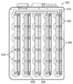
도 1은 본 발명에 따른 제1 예시적인 모선을 갖는 예시적인 멀티 코어 리튬 이온 배터리의 분해 사시도이다.
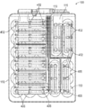
도 2는 본 발명에 따른 도 1의 예시적인 멀티 코어 리튬 이온 배터리(덮개가 제거됨)의 평면도이다.
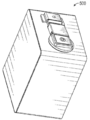
도 3은 본 발명에 따른 도 1 및 도 2의 어셈블링된 예시적인 멀티 코어 리튬 이온 배터리의 사시도이다.
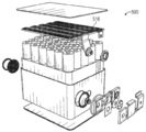
도 4는 본 발명에 따른 제2 예시적인 모선을 갖는 대안적인 예시적인 멀티 코어 리튬 이온 배터리의 분해 사시도이다.
도 5는 본 발명에 따른 도 4의 대안적인 예시적인 멀티 코어 리튬 이온 배터리(덮개가 제거됨)의 평면도이다.
도 6은 본 발명에 따른 도 4 및 도 5의 어셈블링된 예시적인 멀티 코어 리튬 이온 배터리의 사시도이다.
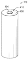
도 7은 본 발명에 따른 예시적인 전기화학 유닛의 상부 사시도이다.BRIEF DESCRIPTION OF THE DRAWINGS The accompanying drawings are referenced to assist those skilled in the art in making and using the disclosed assemblies, systems and methods.
1 is an exploded perspective view of an exemplary multi-core lithium ion battery having a first exemplary busbar according to the present invention.
FIG. 2 is a plan view of the exemplary multi-core lithium ion battery of FIG. 1 (cover removed) according to the present invention.
3 is a perspective view of the assembled multi-core lithium ion battery of FIGS. 1 and 2 according to the present invention.
4 is an exploded perspective view of an alternative exemplary multi-core lithium ion battery having a second exemplary busbar in accordance with the present invention.
5 is a plan view of an alternative exemplary multi-core lithium ion battery of FIG. 4 (cover removed) according to the present invention.
6 is a perspective view of the assembled multi-core lithium ion battery of FIGS. 4 and 5 according to the present invention.
7 is a top perspective view of an exemplary electrochemical unit according to the present invention.
상기에서 언급한 문제들을 극복하고, 대형 각형 셀을 포함하는, 소정 범위의 크기에 대한 안전하고 신뢰성 있는 각형 셀을 실현시키기 위해, 본 발명은 특히, 제작 효율성 및 비용 장점을 제공하는 유리한 설계를 제공한다. 본원에 개시된 설계는 조합하여 사용될 수 있고/있거나 요구되는 각형 셀 시스템을 달성하기 위해 전체적으로 또는 부분적으로 구현될 수 있다. 당업자에게 명백한 바와 같이, 개시된 설계는 광범위한 적용 가능성을 가지고, 배터리 전기 차량(BEV), 플러그-인 하이브리드 전기 차량(PHEV), 하이브리드 전기 차량(HEV), 전기 열차, 그리드 스토리지(GRID), 건설, 광업 및 임업 장비, 포크리프트, 납축전지 대체(LAR), 전기 자전거(ebike), 휴대용 장비(예를 들어, 의료 장비, 마당, 정원 및 조경 툴/장비, 수공구, 등) 및 통상적으로, 다수의 Li-이온 셀을 사용하는 다른 배터리 지지 장치 및 시스템에서 사용하기 위해 설계된 리튬 이온 배터리 시스템을 포함하는, 다수의 적용에서 상당한 이점을 제공한다. 일 예로서, 휴대용 장비의 일반적인 분야에서, 개시된 설계는 더 높은 전압, 예를 들어, 48V를 전달하기 위해 직렬 전기화학 유닛(예를 들어, 10S 시스템)을 포함하고 반복된 시작/정지 작동을 수용하는 구성으로 이용될 수 있다. 본원에 개시된 모선 어셈블리는 배터리 컨테이너 또는 어셈블리 내에서 전기화학 유닛을 재설계하고/하거나 재배치시킬 필요 없이 리튬 이온 배터리에 대한 요구되는 전압/용량 파라미터의 선택을 허용한다.In order to overcome the above-mentioned problems and realize safe and reliable prismatic cells for a range of sizes, including large prismatic cells, the present invention provides, in particular, an advantageous design that provides manufacturing efficiency and cost advantages. do. The designs disclosed herein can be used in combination and/or can be implemented in whole or in part to achieve the desired angular cell system. As will be apparent to those skilled in the art, the disclosed designs have a wide range of applicability, including battery electric vehicles (BEV), plug-in hybrid electric vehicles (PHEV), hybrid electric vehicles (HEV), electric trains, grid storage (GRID), construction, Mining and forestry equipment, forklifts, lead acid battery replacement (LAR), electric bikes, portable equipment (e.g. medical equipment, yards, garden and landscape tools/equipment, hand tools, etc.) and typically, many It provides significant advantages in many applications, including lithium ion battery systems designed for use in other battery support devices and systems using Li-ion cells. As an example, in the general field of portable equipment, the disclosed design includes a series electrochemical unit (e.g., 10S system) to deliver higher voltage, e.g., 48V and accommodates repeated start/stop operation. It can be used as a configuration. The busbar assembly disclosed herein allows for the selection of required voltage/capacity parameters for lithium ion batteries without the need to redesign and/or relocate the electrochemical units within the battery container or assembly.
개시된 설계/시스템이 본원에 참고로 포함된 특허 출원에 기술된 바와 같이, 개별 젤리 롤의 어레이를 이용하여 Li-이온 셀의 맥락에서 주로 기술되어 있지만, 개시된 설계 및 솔루션이 또한, 하나 또는 복수의 셀(예를 들어, AESC, LG에 의해 제조된 것)을 패키징하거나 하나 이상의 분리되지 않은 편평한 권선형 또는 적층된 전극 구조를 갖는 표준 각형 셀(예를 들어, SDI, ATL 및 Panasonic에 의해 제조된 것)을 패키징하는 다른 각형 및 다른 실린더형 셀 시스템에 배치될 수 있다는 것이 당업자에 의해 이해될 것이다. 개시된 설계/시스템은 또한, 밀봉된 Li-이온 셀의 모듈을 캡슐화하기 위해 사용될 수 있다.Although the disclosed designs/systems are primarily described in the context of Li-ion cells using an array of individual jelly rolls, as described in the patent application incorporated herein by reference, the disclosed designs and solutions also may be described in one or more Standard prismatic cells (e.g., manufactured by SDI, ATL, and Panasonic) that package cells (e.g., manufactured by AESC, LG) or have one or more non-separated flat wound or stacked electrode structures It will be understood by those skilled in the art that it may be deployed in different angular and other cylindrical cell systems packaging). The disclosed design/system can also be used to encapsulate modules of sealed Li-ion cells.
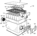
도 1 내지 도 3을 참조하여, 본 발명에 따른 제1 예시적인 리튬 이온 배터리 구현의 개략적 예시가 제공된다. 먼저 도 1을 참조하면, 예시적인 멀티 코어 리튬 이온 배터리(100)의 분해도가 제공된다. 리튬 이온 배터리(100)의 평면도(덮개가 제거됨)는 도 2에 제공되며, 예시적인 리튬 이온 배터리의 조립도는 도 3에 제공된다.1 to 3, a schematic illustration of a first exemplary lithium ion battery implementation according to the present invention is provided. Referring first to FIG. 1, an exploded view of an exemplary multi-core
배터리(100)는 하기와 같이, 구성요소들을 수용하기 위한 내부 영역을 한정하는, 외부 캔 또는 케이싱(102)을 포함한다:The
● 젤리 롤/젤리 롤 슬리브 하위어셈블리를 수용하도록 구성되고 치수화된 복수(30)의 이격된, 실질적으로 실린더형 영역 또는 공동을 한정하는 하우징 또는 지지 구조(106);A housing or
● 지지 구조(106)에서 한정된 실린더형 영역 내에 배치되도록 구성되고 치수화된, 복수(30)의 젤리 롤(110), 즉, 전기화학 유닛;● A plurality of 30
● 그 안에 상기 구성요소들을 케이싱화하기 위해 외장 캔(102)과 협력하도록 구성되고 치수화된 실질적으로 직사각형 상부 커버(120);A substantially rectangular
● 단자 접촉을 용이하게 하는 플랜지 부분(116a, 116b)을 포함하는 일체형(one piece) 모선(116);• One
● 모선(116) 및 외부 BMS 커넥터(121)와 전기적 연통되는 배터리 관리 시스템(BMS)(119);A battery management system (BMS) 119 in electrical communication with the
● 외장 캔(102)에 대해 장착된 배기 어셈블리(200); 및-
● 외장 캔(102)에 대해 외부적으로 장착된 애노드 단자(308) 및 캐소드 단자(310).● An
주목할 것은, 지지체(106) 내에 배치된 젤리 롤(110)은 외장 캔(102) 및 상부 커버(120) 내에서 헤드공간(headspace)을 일반적으로 공유하는 멀티 코어 어셈블리를 한정하지만, 서로 병렬로 연통하지 않는다. 이에 따라, 젤리 롤(110) 중 임의의 하나 이상의 작동과 관련된 압력 및/또는 온도의 임의의 증가는 공유 헤드공간 전반에 걸쳐 확산될 것이고, 필요한 경우에, 개시된 배터리 시스템과 관련된 안전성 특징에 의해 해결될 것이다. 그러나, 제1 젤리 롤(110)과 관련된 전해질은 일반적으로, 하우징(106)에 의해 한정된 실질적으로 실린더형 영역이 일반적으로 병렬적 관점으로부터 서로 젤리 롤(110)을 절연시키도록 설계되기 때문에, 인접한 젤리 롤(110)과 연통하지 않는다. 젤리 롤(110)을 둘러싸고 지지체(106)의 공동 내에 끼워지는 슬리브가 제공될 수 있고, 인접한 젤리 롤(110) 사이에서 병렬적(side-to-side) 전해질 절연에 추가로 기여할 수 있다.Note that the
본 발명의 모선 어셈블리에 특별히 초점을 맞추면, 개시된 모선의 애노드 부분 및 캐소드 부분이 단일 어셈블리 내에 통합된다는 것이 주지된다. 애노드 부분 및 캐소드 부분은 중간 절연 요소에 의해 서로 전기적으로 절연된다. 도 2의 평면도에 도시된 바와 같이, 예시적인 모선(116)은 개별 전기화학 유닛의 애노드 및 캐소드에 대한 전기적 연결을 위한 전기적 연결/용접 포인트를 포함한다. 이에 따라, 도 2에 개략적으로 도시된 바와 같이, 실질적으로 원형 연결/용접 포인트(402)는 각 전기화학 유닛(110) 상에 한정된 중심에 위치된 전기적 연결점/영역, 예를 들어, 니켈 연결 영역(404)(도 7 참조)에 대한 전기적 연결을 용이하게 하기 위해 모선(116)을 따라 이격된다.It is noted that, with particular focus on the busbar assembly of the present invention, the anode and cathode portions of the disclosed busbar are integrated into a single assembly. The anode portion and the cathode portion are electrically insulated from each other by an intermediate insulating element. As shown in the top view of FIG. 2, the
모선(116)은 적절한 전도성 부분, 즉, 모선(116)의 애노드 부분 또는 캐소드 부분이 전기화학 유닛(110)의 전기적 연결 영역과 전기적 연통되도록 유리하게 설계된다. 본원에 도시된 예시적인 구현예에서, 니켈 연결 영역(404)은 전기화학 유닛(110)의 캐소드에 해당하고, 연결/용접 포인트(402)에서 모선(116)의 캐소드 부분과 전기적 연통된다(그리고, 모선(116)의 애노드 부분으로부터 전기적으로 절연된다). 모선(116)의 캐소드 부분은 구리로부터 유리하게 제작될 수 있다.The
또한, 도 2에 개략적으로 도시된 바와 같이, 실질적으로 타원형 연결/용접 포인트(406)는 각 전기화학 유닛(110) 상에 한정된 플랜지-형 전기적 연결 영역, 예를 들어, 알루미늄 연결 영역(408)(도 7 참조)에 대한 전기적 연결을 용이하게 하기 위해 모선(116)을 따라 이격된다. 본원에 도시된 예시적인 구현예에서, 알루미늄 플랜지 영역(408)은 전기화학 유닛(110)의 애노드에 해당하고, 타원형 용접 영역(406)에서 모선(116)의 애노드 부분과 전기적 연통된다(그리고, 모선(116)의 캐소드 부분으로부터 전기적으로 절연된다). 모선(116)의 애노드 부분은 알루미늄으로부터 유리하게 제작될 수 있다.In addition, as schematically shown in FIG. 2, a substantially elliptical connection/
모선(116) 상에 한정된 연결 영역과 관련된 원형/타원형 형상이 예시되어 있으며, 본 발명이 이러한 형상에 의해 또는 이러한 형상으로 제한되지 않는 것으로 이해될 것이다. 오히려, 전기화학 유닛에 대한 모선(116)의 전기적 연결을 위한 연결 영역은 본질적으로 임의의 기하학적 형상을 가질 수 있고, 당업자에게 자명한 바와 같이, 캐소드 연결 및 애노드 연결 둘 모두와 동일할 수 있다. 그러나, 중요한 것은, 모선이 캐소드 부분과 애노드 부분 사이에 전기적 절연이 존재하도록 제작되며 전기화학 유닛의 캐소드/애노드 부분에 대한 전기적 연결의 보존성이 별도로(discretely) 유지되며, 즉, 모선의 애노드 부분이 단지 전기화학 유닛의 애노드와 전기적으로 연통하며, 모선의 캐소드 부분이 단지 전기화학 유닛의 캐소드 부분과 전기적으로 연통한다는 사실이다.A circular/elliptical shape associated with a defined connection area on the
상기에서 주지된 바와 같이, 모선의 전도성 양태는 다양한 전도성 재료, 예를 들어, 금속 재료, 전도성 폴리머 재료, 및 이들의 조합으로부터 제작될 수 있다. 가장 일반적인 전도성 모선 재료는 알루미늄, 구리 및 니켈이다. 개시된 모선의 전도성 양태는 이러한 금속 재료와 관련된 높은 전기 전도성 및 낮은 비용으로 인해 알루미늄 및 구리로부터 유리하게 제작될 수 있다. 전도성 층들 사이에 배치된 절연 재료는 일반적으로, 공지된 비-전도성/절연 재료, 예를 들어, 비전도성 폴리머, 세라믹 및 이들의 조합으로부터 선택된다. 예시적인 절연 재료는 폴리에틸렌, 폴리프로필렌 및 폴리테트라플루오로에틸렌(예를 들어, Teflon™ 재료)을 포함한다.As noted above, the conductive aspect of the busbar can be made from a variety of conductive materials, such as metallic materials, conductive polymer materials, and combinations thereof. The most common conductive busbar materials are aluminum, copper and nickel. The conductive aspects of the disclosed busbars can be advantageously fabricated from aluminum and copper due to the high electrical conductivity and low cost associated with these metallic materials. The insulating material disposed between the conductive layers is generally selected from known non-conductive/insulating materials, such as non-conductive polymers, ceramics and combinations thereof. Exemplary insulating materials include polyethylene, polypropylene and polytetrafluoroethylene (eg, Teflon™ materials).
특별한 리튬 이온 배터리 구현을 위한 모선의 선택은 일반적으로 다양한 파라미터에 의해 유도된다. 예를 들어, 리튬 이온 배터리에 의해 전달되는 용량/전압은 개별 전기화학 유닛이 본 출원에 따라 서로에 대해 전기적으로 연결되는 방식을 유도한다. 또한, 재료의 선택은 예를 들어, 전기화학 유닛의 설계, 및 전도도/저항 파라미터의 측면에서, 내부식성의 고려에 의해 영향을 받을 수 있다. 또한, 모선 설계는 예를 들어, 모선이 적용 가능한 전류 밀도, 등에 대한 신뢰성 있고 안전한 작동을 제공하기 위해 적절한 크기/치수를 갖게 하도록, 배터리의 전체 크기 및 용량에 의해 영향을 받을 수 있다.The choice of busbar for a particular lithium ion battery implementation is generally driven by various parameters. For example, the capacity/voltage delivered by a lithium ion battery leads to the way that the individual electrochemical units are electrically connected to each other according to the present application. In addition, the choice of material can be influenced by consideration of corrosion resistance, for example, in terms of the design of the electrochemical unit, and conductivity/resistance parameters. In addition, the busbar design can be influenced by the overall size and capacity of the battery, for example, to ensure that the busbar has the appropriate size/dimension to provide reliable and safe operation for applicable current density, etc.
도 2에 도시된 바와 같이, 예시적인 모선(116)은 직렬 및 병렬 성질을 조합한 배터리 구성, 상세하게는, 10S-3P 구성을 지지하고 전달한다. 이에 따라, 배터리(100)가 모선(116)과 함께 구현될 때, 직렬로 구성된 전기화학 유닛은 더 높은 전압을 발생시키며, 구성의 병렬 양태는 더 큰 용량에 기여한다.As shown in FIG. 2, the
주목할 것은, 배터리(100) 내에서 전기적 조건을 관리하기 위해 BMS 시스템(119)이 제공된다. 본 발명에 따르면, BMS 시스템(119)은 캔 또는 케이싱(102) 내에 유리하게 배치되고, 전기화학 유닛 "위"에 한정된 공유 대기 영역(123), 즉, 적절한 경우에/적절한 때에 내부 조건을 기초로 하여 각각의 전기화학 유닛이 배기될 수 있는 공유 용적 또는 영역에 위치된다. 배기 어셈블리(200) 및 PDD 어셈블리(300)는 또한, 일반적으로, 리튬 이온 배터리(100)의 안전한 작동을 용이하게 하기 위해 공유 대기 영역(123)과 연통한다. BMS 시스템(119)은 일반적으로 리튬 이온 배터리(100)에 대한 내부의 조건을 반영하는 데이터를 수신할 수 있는 프로세서/처리 시스템에 대한 연결을 용이하게 하고, 프로세서/처리 시스템에 의해 작동되는 이러한 데이터 및 제어 소프트웨어를 기초로 하여 제어 신호를 제공하고, 일반적으로, 당해 분야에 공지된 바와 같이 그 안에 배치된 전기화학 유닛(110)의 직렬 전도도의 측면에서 리튬 이온 배터리(100)의 작동을 관리하는 외부 BMS 커넥터(121)와 전기적 연통한다.Notably, a
도 4 내지 도 6으로 돌아가서, 리튬 이온 배터리(500)는 하기 2가지를 제외하고 도 1 내지 도 3을 참조하여 상기 본원에 기술된 리튬 이온 배터리(100)와 동일하다: (i) 리튬 이온 배터리(500)는 모선(116)과 비교하여 상이한 설계를 특징으로 하는 모선(516)을 포함하고, (ii) 리튬 이온 배터리(500)는 BMS 시스템을 포함하지 않음. 리튬 이온 배터리의 구성이 1S-30P 구성에 해당하기 때문에, BMS 시스템의 부재가 가능하며, BMS 시스템은 일반적으로, 이러한 배터리 구성에서 필요하지 않다.4-6, the
또한 도 5를 참조하면, 모선(516)은 전기화학 유닛의 캐소드 및 애노드에 대한 연결을 위한 전기적 연결점을 포함한다. 모선(116)과 같이, 실질적으로 원형 연결점(602)은 전기화학 유닛(110) 상에 한정된 중심에 위치된 전기적 연결점/영역, 예를 들어, 니켈 연결 영역(404)(도 7 참조)과 전기적 연결을 용이하게 하기 위해 모선(516)을 따라 이격되며, 타원형 연결/용접 포인트(606)는 각 전기화학 유닛(110) 상에 한정된 플랜지-형 전기적 연결 영역, 예를 들어, 알루미늄 연결 영역(408)(도 7 참조)에 대한 전기적 연결을 용이하게 하기 위해 모선(516)을 따라 이격된다. 모선(116)과 같이, 도 5의 모선(516)은 캐소드 부분 및 애노드 부분을 포함하는 다층 적층 구조이다. 이에 따라, 전기적 연결은 리튬 이온 배터리(100)의 설계와 유사한 방식으로 리튬 이온 배터리(500)에서 별도로 달성된다. 그러나, 전기적 연결이 모선(516)에서 나타나는 방식은 모선(116)의 표시(manifestation)와 근본적으로 상이하며, 이에 따라, 전체 병렬 구성이 모선(516) 및 리튬 이온 배터리(100)로 달성된다.Referring also to FIG. 5, the
도 1 내지 도 3과 도 4 내지 도 6의 비교로부터 명백해지는 바와 같이, 근본적으로 상이한 리튬 이온 배터리는 모선(116)의 모선(516)으로의 단순 치환에 의해 달성 가능하다. 대안적인 모선 구성은 또한, 배터리의 내부 구성요소의 재설계 또는 재배치를 필요로 하지 않으면서(BMS 시스템의 가능한 포함/배제를 제외함), 추가 리튬 이온 배터리 변경, 즉, 상이한 직렬/병렬 구성을 여전히 생산하도록 설계/구현될 수 있다. 전기화학 유닛의 동일한 단부 상에(즉, 도 1 및 도 4의 관점으로부터 "상부"에서) 애노드 연결 및 캐소드 연결 둘 모두를 배치시킴으로써, 단일 모선은 애노드/캐소드 연결 둘 모두를 만들기 위해 사용될 수 있으며, 이에 의해, 설정된 리튬 이온 배터리 형성 인자 내에서 모선의 상호교환 능력을 더욱 용이하게 한다.As apparent from the comparison of FIGS. 1 to 3 and 4 to 6, fundamentally different lithium ion batteries are achievable by simple replacement of the
본 발명의 예시적인 구현에 따르면, 개별 배터리 구성/성질을 전달하는 복수의 모선 설계가 설계되고, 제작되고, 목록화된다. 이후에, 특히, 개시된 외부 캔, 내부 지지체 및 복수의 전기화학 유닛을 포함하는 리튬 이온 배터리 하위어셈블리를 제작하는 것이 가능하다. 주지된 하위어셈블리는 각각의 모선 설계와 함께 작동할 것이며, 복수의 선택 중에서 요구되는 모선의 선택을 기초로 하여, 요구되는 전압/용량을 전달하는 리튬 이온 배터리가 생산될 수 있다.According to an exemplary implementation of the invention, a plurality of busbar designs that deliver individual battery configurations/properties are designed, built, and listed. Subsequently, it is possible in particular to fabricate a lithium ion battery subassembly comprising the disclosed outer can, the inner support and a plurality of electrochemical units. The well-known subassemblies will work with each busbar design, and based on the selection of the busbar required among a plurality of options, a lithium ion battery that delivers the required voltage/capacity can be produced.
도 7을 참조하면, 전기화학 유닛(110)은 전해질을 전기화학 유닛에 도입하는 데 사용하기 위한 애퍼처 또는 홀(hole)(410)을 포함할 수 있다. 충전 홀(410)은 위에 모선을 배치시킨 후에 전해질 충전 작업을 가능하게 하기 위해 배치될 수 있지만, 예시적인 구현예는 전기화학 유닛과 전기적 연통하게 모선을 배치시키기 전에 전해질 충전 작업을 고려한다. 예시적인 구현예에서, 진공은 전기화학 유닛 내에 설정되며, 전해질은 전기화학 유닛 내의 진공 조건을 적어도 부분적으로 기초로 하여 충전 홀(410)을 통해 인출된다. 플러그는 전해질의 도입 후에 충전 홀(410)에 적용될 수 있으며, 이러한 플러그는 전기화학 유닛 내의 소정의 조건, 예를 들어, 소정의 압력, 소정의 온도, 또는 이들의 조합을 기초로 하여 파손되도록 구성될 수 있다. 플러그는 다양한 재료, 예를 들어, 왁스로부터 제작될 수 있다.Referring to FIG. 7, the
도 7의 예시적인 전기화학 유닛(110)이 일반적으로, 실질적으로 밀봉된 전기화학 유닛/젤리 롤을 도시하지만, 본 발명은 상세하게, 캔 내에 배치될 때, 각각의 전기화학 유닛/젤리 롤이 캔 내에 한정된 공유 대기/영역과 연통하도록, 밀봉되지 않고 개방된 전기화학 유닛/젤리 롤을 포함하는 리튬 이온 배터리를 고려하는 것으로 이해될 것이다. 이와 관련하여, Lithium Ion Battery라는 명칭을 가지고 전기화학 유닛/젤리 롤과 연통하는 "공유 대기"를 설명하는 미국 특허 제9,685,644호가 참조된다. 미국 특허 제9,685,644호는 본원에서 이미 참고로 포함된다.Although the exemplary
개시된 리튬 이온 배터리와 관련된 예시적인 안전성 특징은 도 1 내지 도 3의 리튬 이온 배터리(100)를 참조로 하여 본원에 기술되고, 배기 어셈블리(200) 및 압력 차단 장치(PDD) 어셈블리(300)를 포함한다. 상응하는 안전성 특징은 또한 당업자에게 자명한 바와 같이, 도 4 내지 도 6의 대안적인 리튬 이온 배터리(500) 내에 도시되고 포함된다. 예시적 배터리(100)에 따르면, 배기 어셈블리(200)와 PDD 어셈블리(300)의 작동 구성요소는 외장 캔(102)의 벽을 따라 장착/배치된다. 그러나, 본 발명을 기초로 당업자에게 명백한 바와 같이, 본 발명의 사상/범위에서 벗어나지 않고, 배기 어셈블리(200) 및/또는 PDD 어셈블리(300) 중 하나 또는 모두의 대안적인 (전체적 또는 부분적) 배치가 달성될 수 있다. 개시된 배기 어셈블리 및 PDD 어셈블리의 추가적인 특징, 기능 및 이점(하기 본원에 기술된 것 이상의 것)은 "Low Profile Pressure Disconnect Device for Lithium Ion Batteries"의 명칭을 갖는 PCT 공개 WO 2017/106349호에 개시되어 있으며, 이러한 문헌은 본원에 이미 참고로 포함되었다.Exemplary safety features associated with the disclosed lithium ion battery are described herein with reference to the
외장 캔 또는 케이싱(102)의 벽은 일반적으로, 개구를 한정한다. 개구를 가로질러 역화 방지기(202) 및 배기 디스크(204)가 장착된다. 밀봉은 역화 방지기(202) 및 배기 디스크(204)의 영역에서, 예를 들어, 배기 어댑터 링에 의해 유지된다. 배기 어댑터 링을 벽에 고정하기 위해 다양한 장착 메커니즘, 예를 들어 용접, 접착제, 기계적 장착 구조 등(이들의 조합을 포함)이 사용될 수 있다. 주목할 것은, 배기 디스크(204)는 벽에 대해 반드시 밀봉식으로 결합되고, 당업계에 알려진 바와 같이, 예를 들어 새김선(들) 및/또는 상부 벽에 비해 감소된 두께에 의해 본래의 환경에서(in situ) 형성될 수 있다는 것이다.The wall of the exterior can or
개별 젤리 롤(또는 다수의 젤리 롤)이 파손되는 경우, 많은 양의 가스가 발생될 수 있고(약 10 리터), 이러한 가스는 고온(약 250 내지 300℃)일 뿐만 아니라 가연성이다. 이러한 가스는 배기가 일어난 후 멀티 젤리 롤 외장의 외부에서 발화할 가능성이 있다. 화염면이 케이싱에 들어가는 것을 방지하기 위해, 메쉬가 제공되어 화염 방지기(202)로서 기능할 수 있고, 유리하게는 배기 영역 상에 위치되거나 배치될 수 있다. 이러한 메쉬는 배출 가스 스트림의 온도를 이의 자동 발화 온도 미만으로 감소시키는 기능을 한다. 메쉬는 열교환기 역할을 하므로, 표면적이 클수록 그리고 개구가 작을수록 더 많은 열이 제거되지만, 메쉬의 개구 면적이 감소하면 배기 중에 메쉬에 가해지는 힘이 증가한다. When an individual jelly roll (or multiple jelly rolls) is broken, a large amount of gas can be generated (about 10 liters), and these gases are not only high temperature (about 250 to 300°C), but also flammable. These gases are likely to ignite outside the multi-jelly roll casing after exhausting. In order to prevent the flame surface from entering the casing, a mesh can be provided to function as the
배터리(100)의 전기적 양태로 돌아가면, 개시된 리튬 이온 배터리를 위한 애노드로서 기능하고 외부 캔 또는 케이싱(102)의 벽에 형성된 개구를 통해 상향으로 연장하도록 구성되고 치수화되는 직립 구리 단자가 일반적으로 제공된다. 직립 단자는 케이싱(102) 내부의 모선(116) 및 플랜지 부분(116a)의 구리 부분과 전기적 연통한다. 직립 구리 단자의 상단은, 외장 캔/케이싱(102)의 벽을 따라 장착된 실질적으로 직사각형인 비전도성(예를 들어, 폴리머) 구조를 한정할 수 있는 퓨즈 홀더(302) 내에 배치된다. 직립 단자는 퓨즈(304)를 통해 단자 접촉면과 전기적으로 연통된다.Returning to the electrical aspect of the
퓨즈(304)는 퓨즈 홀더(302) 내에, 그리고 직립 구리 단자와 전기적으로 연통된 외장 캔/케이싱(102)의 외부에 배치된다. 퓨즈 홀더(302) 및 직립 단자에 대해 퓨즈(304)를 고정하기 위해 단자 나사가 제공될 수 있고, 퓨즈 구성요소들은 퓨즈 커버에 의해 퓨즈 홀더(302) 내에서 전기적으로 절연될 수 있다. The
실질적으로 U자형인 단자(310)는 외장 캔/케이싱(102)의 벽에 장착되어 전기적으로 접촉되는 이격된 플랜지 표면을 한정한다. 케이싱(102) 내부에 있는 모선(116)의 알루미늄 모선 부분은 외장 캔/케이싱(102)과 전기적으로 연통됨으로써 단자(310)와 전기적 연통을 설정한다. 당업자에게 자명한 바와 같이, 단자(310)는 다양한 기하학적 형태를 가질 수 있다. 단자(310)는 통상적으로, 알루미늄으로부터 제작되고, 개시된 리튬 이온 배터리용 캐소드로서 기능한다.The substantially
이에 따라, 애노드 단자 접촉면(308) 및 캐소드 단자(310)는 케이싱(102)의 벽에 병렬적(side-by-side) 관계로 배치되고 전기적 연결이 가능하므로, 배터리(100)로부터 원하는 용도(들)에 에너지를 공급하도록 할 수 있다.Accordingly, since the anode
예시적 PDD 어셈블리(300)를 참조하면, 외장 캔/케이싱(102)의 벽에 한정된 다른 개구에 대해 전도성 돔이 배치된다. 돔은 처음에 외장 캔/케이싱(102)에 대해 내측으로 휘어져 있고, 이에 따라 돔의 외향/상향 휨에 의해 외장 캔 내의 압력 증가에 응답하도록 배치된다. 돔은 통상적으로 벽에 대해 용접되어 있는 돔 어댑터 링에 의해 벽에 대해 장착될 수 있다. 예시적 구현에서 그리고 제조의 용이성을 위해, 돔 어댑터 링은 돔 둘레에 미리 용접될 수 있고, 이에 따라 돔 어댑터 링에 의해 제공되는 증가된 표면적으로 인해 벽에 대한 돔의 장착과 관련된 용접 작업을 용이하게 할 수 있다.Referring to the
사용시 그리고 외장 캔/케이싱(102) 및 상부 커버(120)에 의해 한정된 어셈블리 내 압력 상승에 응답하여, 돔은 외장 캔/케이싱(102)의 벽에 대해 위로 휘어질 것이다. 충분히 위로 휘어지면(즉, 임계 레벨에 도달한 배터리(100)와 관련된 내부 압력에 기초한 휨), 차단 해머는 퓨즈 홀더(302) 내 퓨즈(304)와 전기적으로 연통된 단자 접촉면의 하측과 접촉된다. 차단 해머(전도성임) 간의 접촉은 회로를 완성하고, 퓨즈(302)를 "블로우(blow)"되게 하여, 외장 캔(102) 및 상부 커버(120)에 의해 한정된 어셈블리 내에 배치된 멀티 코어 구성요소로부터 회로를 파괴시킨다. 전류는 외장 캔(102)을 통해 우회된다. 주목할 것은, 휨 돔(312)을 제외하고 PDD 어셈블리(300)의 모든 작동 구성요소는 외장 캔(102) 및 상부 커버(120)의 외부에 유리하게 배치된다.In use and in response to pressure rise in the assembly defined by the exterior can/
본 발명의 PPD 및/또는 배기 구조를 지지하기 위해 어떤 중간 구조 또는 보조 구조도 필요하지 않다. 실제로, 본 발명의 구현예에 따라 배터리의 내부에 대한 하나의 추가 개구, 즉 Cu 단자의 통로를 수용하기 위한 개구만 필요하다. 개시된 배터리 시스템의 단순성 및 제조/조립 용이성은 개시된 배터리 시스템의 제조 가능성 및 비용 파라미터를 개선한다. 또한, 개시된 배터리의 캔 및/또는 덮개에 대한 PDD 및 배기 어셈블리의 직접 장착은 개시된 배터리의 로우 프로파일(low profile)을 더 향상시킨다. 로우 프로파일이란 배터리 시스템의 높은, 예를 들어 30 Ah 이상의 용량을 전달하면서, 개시된 PDD 및 배기 안전 구조/시스템을 수용하는 데 필요한 용적 또는 공간의 감소를 의미한다.No intermediate structure or auxiliary structure is needed to support the PPD and/or exhaust structure of the present invention. Indeed, according to an embodiment of the invention, only one additional opening to the interior of the battery, ie an opening for receiving the passage of the Cu terminal, is needed. The simplicity and ease of manufacture/assembly of the disclosed battery system improves the manufacturability and cost parameters of the disclosed battery system. In addition, direct mounting of the PDD and exhaust assembly to the can and/or lid of the disclosed battery further improves the low profile of the disclosed battery. Low profile refers to the reduction in volume or space required to accommodate the disclosed PDD and exhaust safety structures/systems, while delivering a high, eg 30 Ah or higher capacity of the battery system.
예시적 멀티 코어 리튬 이온 배터리 시스템/어셈블리Exemplary multi-core lithium ion battery system/assembly
본 발명의 예시적 구현예에서, 멀티 코어 리튬 이온 배터리 컨테이너의 덮개에 배기 구조가 한정된다. 배기 압력에 도달하면, 배기 구조가 금속 뚜껑, 즉 배기 구조의 새겨지지 않은 영역에 대해 휘어짐에 따라 새김선을 따라 배기 구조의 실질적으로 순간적인 파손이 발생하여, 배기 개구로부터 (30 메쉬 역화 방지기를 통해) 압력/가스를 방출한다.In an exemplary embodiment of the invention, an exhaust structure is defined in the cover of a multi-core lithium ion battery container. When the exhaust pressure is reached, substantially instantaneous breakage of the exhaust structure along the indentation occurs as the exhaust structure bends against the metal lid, i.e., the unengraved area of the exhaust structure, resulting in a (30 mesh backfire protector Release pressure/gas).
본 발명에 따른 유리한 멀티 코어 리튬 이온 배터리 구조는 배터리의 어레이의 용이한 조립 및 전력 대 에너지 비율을 맞출 수 있는 능력과 같은 대형 배터리의 이점을 제공하면서, 제조 비용의 감소 및 안전성 개선을 제공한다. 본원에 개시된 유리한 시스템들은 멀티 코어 셀 구조 및 멀티 셀 배터리 모듈에 적용 가능하다. 당업자는 하기에 기술된 Li 이온 구조가 대부분의 경우에 젤리 롤과 같은 활성 코어 및 전해질을 이용하는 기타 전기화학 유닛용으로 이용될 수도 있음을 이해한다. 가능한 대안적인 구현예로는 미국 특허 제8,233,267호에 기술된 것들과 같은 울트라 커패시터, 그리고 니켈 금속 수소화물 배터리 또는 권취 납 축전지 시스템을 포함한다. The advantageous multi-core lithium ion battery structure according to the present invention provides advantages of large batteries such as easy assembly of the array of batteries and the ability to match the power-to-energy ratio, while reducing manufacturing costs and improving safety. The advantageous systems disclosed herein are applicable to multi-core cell structures and multi-cell battery modules. Those skilled in the art understand that the Li ion structures described below may be used in most cases for other electrochemical units using active cores and electrolytes such as jelly rolls. Possible alternative embodiments include ultra capacitors such as those described in US Pat. No. 8,233,267, and nickel metal hydride batteries or wound lead acid battery systems.
본 발명에 따르면, 지지 부재가 내부에 배치된 밀봉된 외장을 갖는 예시적인 멀티 코어 리튬 이온 배터리도 기술된다. 지지 부재는 복수의 공동, 및 복수의 공동 중 상응하는 하나의 공동 내에 배치된 복수의 리튬 이온 코어 부재를 포함한다. 복수의 공동 라이너가 존재하고, 각각의 공동 라이너는 상응하는 하나의 리튬 이온 코어 부재와, 상응하는 하나의 공동의 표면 사이에 배치된다. 지지 부재는 운동 에너지 흡수 재료를 포함하고, 운동 에너지 흡수 재료는 알루미늄 폼, 세라믹 및 플라스틱 중 하나로 형성된다. 플라스틱 또는 알루미늄 재료로 형성된 공동 라이너가 존재하고, 복수의 공동 라이너는 단일체형 라이너 부재의 일부로서 형성된다. 코어 부재들을 수용하기 위하여, 플라스틱 라이너 대신 개방형 알루미늄 실린더형 슬리브 또는 캔 구조도 이용될 수 있다. 각각의 코어 내에 들어있는 전해질이 추가로 포함되고, 전해질은 내연제, 가스 발생제, 및 산화환원 셔틀 중 적어도 하나를 포함한다. 각각의 리튬 이온 코어 부재는 애노드, 캐소드 및 각각의 애노드와 캐소드 사이에 배치된 세퍼레이터를 포함한다. 코어 부재를 밀봉된 외장 외부의 전기 단자에 전기적으로 연결하는 전기 커넥터가 상기 외장 내에 추가로 포함된다. According to the present invention, an exemplary multi-core lithium ion battery with a sealed sheath with a support member disposed therein is also described. The support member includes a plurality of cavities, and a plurality of lithium ion core members disposed within a corresponding one of the plurality of cavities. There are a plurality of cavity liners, each cavity liner being disposed between the corresponding one lithium ion core member and the surface of the corresponding one cavity. The support member includes a kinetic energy absorbing material, and the kinetic energy absorbing material is formed of one of aluminum foam, ceramic and plastic. There is a cavity liner formed of a plastic or aluminum material, and the multiple cavity liners are formed as part of a monolithic liner member. To accommodate the core members, an open aluminum cylindrical sleeve or can structure can also be used instead of a plastic liner. An electrolyte contained in each core is further included, and the electrolyte includes at least one of a flame retardant, a gas generator, and a redox shuttle. Each lithium ion core member includes an anode, a cathode, and a separator disposed between each anode and cathode. An electrical connector that electrically connects the core member to an electrical terminal outside the sealed exterior is further included within the exterior.
본 발명의 다른 양태에서, 코어 부재는 병렬로 연결되거나, 직렬로 연결된다. 대안적으로, 코어 부재의 제1 세트는 병렬로 연결되고 코어 부재의 제2 세트는 병렬로 연결되고, 코어 부재의 제1 세트는 코어 부재의 제2 세트와 직렬로 연결된다. 지지 부재는 벌집 구조의 형태이다. 운동 에너지 흡수 재료는 압축가능 매체를 포함한다. 외장은 압축가능 요소를 갖는 벽을 포함하고, 압축가능 요소는, 벽에 충격을 가하는 힘으로 인해 압축될 때, 리튬 이온 배터리의 전기적 단락 회로를 생성한다. 지지 부재 내의 공동 및 이에 상응하는 코어 부재는 실린더형, 장방형, 및 각형 형상 중 하나이다. 공동 중 적어도 하나 및 이에 상응하는 코어 부재는 다른 공동 및 이에 상응하는 코어 부재와는 다른 형상을 가질 수 있다.In another aspect of the invention, the core members are connected in parallel or connected in series. Alternatively, the first set of core members are connected in parallel, the second set of core members are connected in parallel, and the first set of core members are connected in series with the second set of core members. The support member is in the form of a honeycomb structure. Kinetic energy absorbing materials include compressible media. The sheath includes a wall with a compressible element, and the compressible element creates an electrical short circuit of the lithium ion battery when compressed due to the force exerting a shock on the wall. The cavity in the support member and the corresponding core member are one of cylindrical, rectangular, and angular shapes. At least one of the cavities and the corresponding core member may have a different shape from the other cavities and the corresponding core member.
본 발명의 다른 양태에서, 코어 부재 중 적어도 하나는 높은 전력 특성을 갖고, 코어 부재 중 적어도 하나는 높은 에너지 특성을 갖는다. 코어 부재의 애노드는 동일한 재료로 형성되고, 코어 부재의 캐소드는 동일한 재료로 형성된다. 각각의 세퍼레이터 부재는 세라믹 코팅을 포함할 수 있고, 각각의 애노드 및 각각의 캐소드는 세라믹 코팅을 포함할 수 있다. 코어 부재 중 적어도 하나는 다른 코어 부재의 애노드 및 캐소드의 두께와는 다른 두께의 애노드 및 캐소드 중 하나를 포함한다. 적어도 하나의 캐소드는 화합물 A 내지 M 그룹의 재료 중 적어도 2개를 포함한다. 각각의 캐소드는 표면 개질제를 포함한다. 각각의 애노드는 탄소 또는 흑연 중 하나 또는 Li 금속을 포함한다. 각각의 애노드는 Si를 포함한다. 각각의 코어 부재는 압연된 애노드, 캐소드 및 세퍼레이터 구조를 포함하거나, 각각의 코어 부재는 적층된 애노드, 캐소드 및 세퍼레이터 구조를 포함한다.In another aspect of the present invention, at least one of the core members has high power characteristics, and at least one of the core elements has high energy characteristics. The anode of the core member is formed of the same material, and the cathode of the core member is formed of the same material. Each separator member can include a ceramic coating, and each anode and each cathode can include a ceramic coating. At least one of the core members includes one of the anodes and cathodes of a thickness different from the thickness of the anodes and cathodes of the other core members. The at least one cathode comprises at least two of the materials of groups A to M. Each cathode contains a surface modifier. Each anode contains either a carbon or graphite or Li metal. Each anode contains Si. Each core member includes a rolled anode, cathode, and separator structure, or each core member includes a stacked anode, cathode, and separator structure.
본 발명의 다른 양태에서, 코어 부재는 실질적으로 동일한 전기 용량을 갖는다. 코어 부재 중 적어도 하나는 다른 코어 부재와 비교하여 상이한 전기 용량을 갖는다. 코어 부재 중 적어도 하나는 전력 저장을 위해 최적화되고, 코어 부재 중 적어도 하나는 에너지 저장을 위해 최적화된다.In another aspect of the invention, the core member has substantially the same electrical capacity. At least one of the core members has a different electric capacity compared to other core members. At least one of the core members is optimized for power storage, and at least one of the core members is optimized for energy storage.
본 발명의 또 다른 양태에서, 코어 부재의 전기적 모니터링(monitoring) 및 밸런싱(balancing)을 가능하게 하도록 구성된, 코어 부재와 전기적으로 상호 연결된 감지 와이어(sensing wire)가 포함된다. 밀봉된 외장은 난연성 부재를 포함하고, 난연성 부재는 외장의 외면에 부착된 난연성 메쉬 재료를 포함한다.In another aspect of the present invention, a sensing wire electrically connected to the core member, configured to enable electrical monitoring and balancing of the core member, is included. The sealed sheath comprises a flame retardant member, and the flame retardant member comprises a flame retardant mesh material attached to the exterior surface of the sheath.
다른 구현예에서, 밀봉된 외장을 포함하는 멀티 코어 리튬 이온 배터리가 기술된다. 복수의 공동을 포함하는 지지 부재가 밀봉된 외장 내에 배치되고, 지지 부재는 운동 에너지 흡수 재료를 포함한다. 복수의 공동 중 상응하는 하나의 공동 내에 배치된 복수의 리튬 이온 코어 부재가 존재한다. 복수의 공동 라이너가 추가로 포함되고, 각각의 공동 라이너는 상응하는 하나의 리튬 이온 코어 부재와, 상응하는 하나의 공동의 표면 사이에 배치된다. 공동 라이너는 플라스틱 또는 알루미늄 재료(예를 들어, 폴리머 및 금속 포일 적층 파우치)로 형성되고, 복수의 공동 라이너는 단일체형 라이너 부재의 일부로서 형성될 수 있다. 운동 에너지 흡수 재료는 알루미늄 폼, 세라믹 및 플라스틱 중 하나로 형성된다. In another embodiment, a multi-core lithium ion battery comprising a sealed enclosure is described. A support member comprising a plurality of cavities is disposed in a sealed enclosure, the support member comprising a kinetic energy absorbing material. There are a plurality of lithium ion core members disposed within a corresponding one of the plurality of cavities. A plurality of cavity liners are further included, each cavity liner being disposed between a corresponding one lithium ion core member and the surface of the corresponding one cavity. The cavity liner is formed of a plastic or aluminum material (eg, polymer and metal foil laminated pouches), and the plurality of cavity liners can be formed as part of a monolithic liner member. The kinetic energy absorbing material is formed of one of aluminum foam, ceramic and plastic.
본 발명의 다른 양태에서, 각각의 코어 내에 전해질이 들어있고, 전해질은 내연제, 가스 발생제, 및 산화환원 셔틀 중 적어도 하나를 포함한다. 각각의 리튬 이온 코어 부재는 애노드, 캐소드 및 각각의 애노드와 캐소드 사이에 배치된 세퍼레이터를 포함한다. 코어 부재를 밀봉된 외장 외부의 전기 단자에 전기적으로 연결하는 전기 커넥터가 외장 내에 추가로 포함된다. 코어 부재는 병렬로 연결될 수 있다. 코어 부재는 직렬로 연결될 수 있다. 코어 부재의 제1 세트는 병렬로 연결될 수 있고 코어 부재의 제2 세트는 병렬로 연결될 수 있으며, 코어 부재의 제1 세트는 코어 부재의 제2 세트와 직렬로 연결될 수 있다.In another aspect of the present invention, an electrolyte is contained in each core, and the electrolyte includes at least one of an internal flame retardant, a gas generator, and a redox shuttle. Each lithium ion core member includes an anode, a cathode, and a separator disposed between each anode and cathode. An electrical connector that electrically connects the core member to an electrical terminal outside the sealed exterior is further included within the exterior. The core members can be connected in parallel. The core members can be connected in series. The first set of core members can be connected in parallel, the second set of core members can be connected in parallel, and the first set of core members can be connected in series with the second set of core members.
다른 양태에서, 지지 부재는 벌집 구조의 형태이다. 운동 에너지 흡수 재료는 압축가능 매체를 포함한다. 리튬 외장은 압축가능 요소를 갖는 벽을 포함하고, 압축가능 요소는, 벽에 충격을 가하는 힘으로 인해 압축될 때, 리튬 이온 배터리의 전기적 단락 회로를 생성한다. 지지 부재 내의 공동 및 이에 상응하는 코어 부재는 실린더형, 장방형, 및 각형 형상 중 하나이다. 공동 중 적어도 하나 및 이에 상응하는 코어 부재는 다른 공동 및 이에 상응하는 코어 부재와 비교하여 상이한 형상을 가질 수 있다. 코어 부재 중 적어도 하나는 높은 전력 특성을 가질 수 있고, 코어 부재 중 적어도 하나는 높은 에너지 특성을 가질 수 있다. 코어 부재의 애노드는 동일한 재료로 형성될 수 있고, 코어 부재의 캐소드는 동일한 재료로 형성될 수 있다. 각각의 세퍼레이터 부재는 세라믹 코팅을 포함할 수 있다. 각각의 애노드 및 각각의 캐소드는 세라믹 코팅을 포함할 수 있다. 코어 부재 중 적어도 하나는 다른 코어 부재의 애노드 및 캐소드의 두께와 비교하여 상이한 두께의 애노드 및 캐소드 중 하나를 포함할 수 있다.In another aspect, the support member is in the form of a honeycomb structure. Kinetic energy absorbing materials include compressible media. The lithium sheath includes a wall with a compressible element, which when compressed due to the force exerting a shock on the wall creates an electrical short circuit of the lithium ion battery. The cavity in the support member and the corresponding core member are one of cylindrical, rectangular, and angular shapes. At least one of the cavities and the corresponding core member may have different shapes compared to other cavities and the corresponding core member. At least one of the core members may have high power characteristics, and at least one of the core members may have high energy characteristics. The anode of the core member can be formed of the same material, and the cathode of the core member can be formed of the same material. Each separator member can include a ceramic coating. Each anode and each cathode can include a ceramic coating. At least one of the core members may include one of anodes and cathodes of different thicknesses compared to the thicknesses of the anodes and cathodes of other core members.
또 다른 양태에서, 적어도 하나의 캐소드는 화합물 A 내지 M 그룹의 재료 중 적어도 2개를 포함한다. 각각의 캐소드는 표면 개질제를 포함할 수 있다. 각각의 애노드는 Li 금속, 탄소, 흑연 또는 Si를 포함한다. 각각의 코어 부재는 압연된 애노드, 캐소드 및 세퍼레이터 구조를 포함할 수 있다. 각각의 코어 부재는 적층된 애노드, 캐소드 및 세퍼레이터 구조를 포함할 수 있다. 코어 부재는 실질적으로 동일한 전기 용량을 가질 수 있다. 코어 부재 중 적어도 하나는 다른 코어 부재와 비교하여 상이한 전기 용량을 가질 수 있다. 코어 부재 중 적어도 하나는 전력 저장을 위해 최적화될 수 있고, 코어 부재 중 적어도 하나는 에너지 저장을 위해 최적화될 수 있다.In another aspect, at least one cathode comprises at least two of the materials of the compounds A-M group. Each cathode can include a surface modifier. Each anode contains Li metal, carbon, graphite or Si. Each core member can include a rolled anode, cathode, and separator structure. Each core member may include a stacked anode, cathode, and separator structure. The core member can have substantially the same electrical capacity. At least one of the core members may have a different electric capacity compared to other core members. At least one of the core members can be optimized for power storage, and at least one of the core members can be optimized for energy storage.
본 발명의 다른 구현예에서, 감지 와이어는 코어 부재의 전기적 모니터링 및 밸런싱을 가능하게 하도록 구성된 코어 부재와 전기적으로 상호 연결된다. 밀봉된 외장은 난연성 부재를 포함할 수 있고, 난연성 부재는 외장의 외면에 부착된 난연성 메쉬 재료를 포함할 수 있다.In another embodiment of the present invention, the sensing wire is electrically interconnected with a core member configured to enable electrical monitoring and balancing of the core member. The sealed sheath may include a flame retardant member, and the flame retardant member may include a flame retardant mesh material attached to the outer surface of the sheath.
다른 구현예에서, 외장 내부에 리튬 이온 셀 영역 및 공유 대기 영역이 있는 밀봉된 외장을 포함하는 멀티 코어 리튬 이온 배터리가 기술된다. 지지 부재는 밀봉된 외장의 리튬 이온 셀 영역 내에 배치되고, 지지 부재는 복수의 공동을 포함하며, 각각의 공동은 공유 대기 영역에 대해서 개방된 말단부를 갖는다. 복수의 리튬 이온 코어 부재가 제공되는데, 각각의 리튬 이온 코어 부재는 복수의 공동 중 상응하는 공동 내에 배치된 애노드 및 캐소드를 가지고 있고, 애노드 및 캐소드는 공동의 개방 말단부에 의해서 공유 대기 영역에 노출되고, 애노드 및 캐소드는 이들의 길이를 따라 공동에 의해 실질적으로 둘러싸여 있다. 지지 부재는 운동 에너지 흡수 재료를 포함할 수 있다. 운동 에너지 흡수 재료는 알루미늄 폼, 세라믹 및 플라스틱 중 하나로 형성된다.In another embodiment, a multi-core lithium ion battery is described that includes a sealed sheath with a lithium ion cell region and a shared standby region inside the sheath. The support member is disposed within a sealed sheath lithium ion cell region, and the support member includes a plurality of cavities, each cavity having an open end with respect to the shared atmosphere region. A plurality of lithium ion core members are provided, each lithium ion core member having an anode and a cathode disposed within corresponding cavities of the plurality of cavities, the anode and cathode being exposed to the shared atmospheric region by the open end of the cavity , The anode and cathode are substantially surrounded by cavities along their length. The support member can include a kinetic energy absorbing material. The kinetic energy absorbing material is formed of one of aluminum foam, ceramic and plastic.
다른 양태에서, 복수의 공동 라이너가 존재하고, 각각의 공동 라이너는 상응하는 하나의 리튬 이온 코어 부재와, 상응하는 하나의 공동의 표면 사이에 배치된다. 공동 라이너는 플라스틱 또는 알루미늄 재료로 형성될 수 있다. 복수의 공동 라이너는 단일체형 라이너 부재의 일부로서 형성될 수 있다. 각각의 코어 내에 전해질이 들어있고, 전해질은 내연제, 가스 발생제, 및 산화환원 셔틀 중 적어도 하나를 포함할 수 있다. 각각의 리튬 이온 코어 부재는 애노드, 캐소드 및 각각의 애노드와 캐소드 사이에 배치된 세퍼레이터를 포함한다. 코어 부재를 밀봉된 외장 외부의 전기 단자에 전기적으로 연결하는 전기 커넥터가 외장 내에 존재한다.In another aspect, a plurality of cavity liners are present, each cavity liner being disposed between a corresponding one lithium ion core member and the surface of the corresponding one cavity. The cavity liner can be formed from a plastic or aluminum material. The plurality of cavity liners may be formed as part of a monolithic liner member. An electrolyte is contained in each core, and the electrolyte may include at least one of a flame retardant, a gas generator, and a redox shuttle. Each lithium ion core member includes an anode, a cathode, and a separator disposed between each anode and cathode. An electrical connector exists within the sheath to electrically connect the core member to an electrical terminal outside the sealed sheath.
또 다른 양태에서, 코어 부재는 병렬로 연결되거나 코어 부재는 직렬로 연결된다. 대안적으로, 코어 부재의 제1 세트는 병렬로 연결되고 코어 부재의 제2 세트는 병렬로 연결되고, 코어 부재의 제1 세트는 코어 부재의 제2 세트와 직렬로 연결된다.In another aspect, the core members are connected in parallel or the core members are connected in series. Alternatively, the first set of core members are connected in parallel, the second set of core members are connected in parallel, and the first set of core members are connected in series with the second set of core members.
다른 구현예에서, 리튬 이온 배터리가 기술되고, 밀봉된 외장 및 밀봉된 외장 내에 배치된 적어도 하나의 리튬 이온 코어 부재를 포함한다. 리튬 이온 코어 부재는 애노드 및 캐소드를 포함하고, 캐소드는 화합물 A 내지 M의 그룹으로부터 선택되는 적어도 2개의 화합물을 포함한다. 하나의 리튬 이온 코어 부재만 존재할 수 있다. 밀봉된 외장은 폴리머 백(bag)일 수 있거나, 밀봉된 외장은 금속 용기일 수 있다. 각각의 캐소드는 화합물 B, C, D, E, F, G, L 및 M의 그룹으로부터 선택되는 적어도 2개의 화합물을 포함할 수 있고, 표면 개질제를 더 포함할 수 있다. 각각의 캐소드는 화합물 B, D, F, G 및 L의 그룹으로부터 선택되는 적어도 2개의 화합물을 포함할 수 있다. 배터리는 4.2 V보다 더 높은 전압까지 충전될 수 있다. 각각의 애노드는 탄소 및 흑연 중 하나를 포함할 수 있다. 각각의 애노드는 Si를 포함할 수 있다.In another embodiment, a lithium ion battery is described and includes a sealed sheath and at least one lithium ion core member disposed within the sealed sheath. The lithium ion core member comprises an anode and a cathode, and the cathode comprises at least two compounds selected from the group of compounds A to M. Only one lithium ion core member may be present. The sealed sheath can be a polymer bag, or the sealed sheath can be a metal container. Each cathode may include at least two compounds selected from the group of compounds B, C, D, E, F, G, L and M, and may further include a surface modifier. Each cathode may include at least two compounds selected from the group of compounds B, D, F, G and L. The battery can be charged to a voltage higher than 4.2 V. Each anode may include one of carbon and graphite. Each anode may contain Si.
또 다른 구현예에서, 밀봉된 외장 및 밀봉된 외장 내에 배치된 적어도 하나의 리튬 이온 코어 부재를 갖는 리튬 이온 배터리가 기술된다. 리튬 이온 코어 부재는 애노드 및 캐소드를 포함한다. 외장 내의 전기 커넥터는 적어도 하나의 코어 부재를 밀봉된 외장 외부의 전기 단자에 전기적으로 연결하고; 전기 커넥터는, 소정의 전류가 초과되었을 때, 전기 커넥터를 통해 전류가 흐르는 것을 차단시키기 위한 수단/메커니즘/구조를 포함한다.In another embodiment, a lithium ion battery having a sealed sheath and at least one lithium ion core member disposed within the sealed sheath is described. The lithium ion core member includes an anode and a cathode. The electrical connector in the sheath electrically connects the at least one core member to an electrical terminal outside the sealed sheath; The electrical connector includes means/mechanism/structure for blocking current from flowing through the electrical connector when a predetermined current is exceeded.
본 발명은, 예를 들어 열/온도 조건을 관리하고 잠재적인 열 폭주 조건의 가능성 및/또는 규모를 감소시킴으로써, 특히 배터리의 안전성 및/또는 안정성에 기여하는 유리한 흡열 기능을 제공하는 재료를 포함하는 리튬 이온 배터리를 더 제공한다. 본 발명의 예시적인 구현예에서, 흡열 재료/시스템은 무기 가스 발생 흡열 재료를 포함하는 세라믹 매트릭스를 포함한다. 개시된 흡열 재료/시스템은 아래에서 더욱 상세히 기술되는 바와 같이 다양한 방식 및 다양한 레벨로 리튬 배터리에 도입될 수 있다.The present invention comprises materials that provide advantageous endothermic functions, particularly contributing to the safety and/or stability of the battery, for example by managing thermal/temperature conditions and reducing the likelihood and/or scale of potential thermal runaway conditions. A lithium ion battery is further provided. In an exemplary embodiment of the present invention, the endothermic material/system comprises a ceramic matrix comprising an inorganic gas generating endothermic material. The disclosed endothermic materials/systems can be introduced into lithium batteries in a variety of ways and levels, as described in more detail below.
사용에 있어서, 개시된 흡열 재료/시스템은, 온도가 소정의 레벨, 예컨대, 정상 작동과 관련된 최대 레벨을 초과하여 상승하는 경우, 흡열 재료/시스템이 열 폭주의 가능성을 방지 및/또는 최소화하기 위한 목적으로 하나 이상의 기능을 제공하는 역할을 하도록 작동한다. 예를 들어, 개시된 흡열 재료/시스템은 유리하게는 다음의 기능 중 하나 이상을 제공할 수 있다: (i) (특히 고온에서) 단열; (ii) 에너지 흡수; (iii) 흡열 재료/시스템과 관련된 흡열 반응(들)으로부터, 전체적으로 또는 부분적으로, 생성된 가스의 배기, (iv) 배터리 구조 내의 전체 압력 상승; (v) 흡열 재료/시스템과 관련된 흡열 반응(들) 중에 생성된 가스의 배기를 통한 배터리 시스템으로부터 흡수 열의 제거, 및/또는 (vi) 유독 가스(존재할 경우)의 희석 및 배터리 시스템으로부터 (전체적으로 또는 부분적으로) 유독 가스의 안전한 방출. 또한, 흡열 반응(들)과 관련된 배기 가스는 전해질 가스를 희석시켜 전해질 가스와 관련된 발화점 및/또는 가연성을 늦추거나 제거할 기회를 제공한다는 점이 주목된다. In use, the disclosed endothermic material/system is intended to prevent and/or minimize the likelihood of thermal runaway if the temperature rises above a certain level, such as a maximum level associated with normal operation. It acts as a role providing one or more functions. For example, the disclosed endothermic material/system can advantageously provide one or more of the following functions: (i) thermal insulation (especially at high temperatures); (ii) energy absorption; (iii) exhaustion of the generated gas, in whole or in part, from endothermic reaction(s) associated with the endothermic material/system, (iv) overall pressure rise in the battery structure; (v) removal of absorbed heat from the battery system through exhaust of gas generated during the endothermic reaction(s) associated with the endothermic material/system, and/or (vi) dilution of toxic gases (if present) and from the battery system (total or Partially) Safe release of toxic gases. It is also noted that the exhaust gas associated with the endothermic reaction(s) dilutes the electrolyte gas, providing an opportunity to slow or eliminate the ignition point and/or flammability associated with the electrolyte gas.
개시된 흡열 재료/시스템의 단열 특성은 이러한 흡열 재료/시스템을 리튬 이온 배터리 시스템에 적용하는 상이한 단계들에서 그 성질들을 조합하는 데 유리하다. 제조된 대로의 상태에서, 흡열 재료/시스템은 작은 온도 상승 동안, 또는 열적 이벤트의 초기 부분 동안 단열을 제공한다. 이러한 비교적 낮은 온도에서, 단열 기능은 열 에너지를 열 용량 전체에 서서히 확산시키기 위하여 제한된 전도를 허용하는 한편, 열 발생을 억제하는 작용을 한다. 이러한 낮은 온도에서, 흡열 재료/시스템 재료는 어떤 흡열 가스 발생 반응도 겪지 않도록 선택 및/또는 설계된다. 이는 전체적으로 단열 및/또는 리튬 이온 배터리에 어떤 영구적인 손상도 입히지 않고 온도 이탈을 가능하게 하는 창(window)을 제공한다. 리튬 이온 타입의 저장 장치의 경우, 이탈 또는 낮은 레벨의 상승과 관련된 일반적인 범위는 60℃ 내지 200℃이다. 언급된 온도 범위에서 흡열 반응에 견디는 무기 흡열 재료/시스템의 선택을 통해, 원하는 높은 온도에서 제2의 흡열 기능을 개시하는 리튬 이온 배터리가 제공될 수 있다. 따라서, 본 발명에 따르면, 개시된 흡열 재료/시스템과 관련된 흡열 반응(들)은 60℃에서 200℃를 훨씬 초과하는 온도까지의 온도 범위에서 먼저 개시되는 것이 일반적으로 바람직하다. 본 발명에 따른 사용을 위한 예시적인 흡열 재료/시스템은 하기 표 3에 기재된 것들을 포함하나, 이에 한정되는 것은 아니다.The thermal insulation properties of the disclosed endothermic material/system are advantageous for combining its properties at different stages of applying this endothermic material/system to a lithium ion battery system. As manufactured, the endothermic material/system provides thermal insulation during a small temperature rise or during the initial portion of a thermal event. At these relatively low temperatures, the adiabatic function allows limited conduction in order to slowly spread the thermal energy throughout the heat capacity, while acting to suppress heat generation. At these low temperatures, the endothermic material/system material is selected and/or designed so that it does not undergo any endothermic gas generation reaction. This provides a window that allows the temperature to escape without causing any permanent damage to the thermally insulating and/or lithium ion batteries as a whole. In the case of a lithium ion type storage device, the typical range associated with departure or low level rise is 60°C to 200°C. Through the selection of inorganic endothermic materials/systems that withstand endothermic reactions in the stated temperature range, lithium ion batteries can be provided that initiate a second endothermic function at a desired high temperature. Accordingly, according to the present invention, it is generally preferred that the endothermic reaction(s) associated with the disclosed endothermic material/system is first initiated in a temperature range from 60° C. to temperatures well above 200° C. Exemplary endothermic materials/systems for use in accordance with the present invention include, but are not limited to, those listed in Table 3 below.
표 3Table 3

통상적으로, 이들 흡열 재료는 가능하게는 기타 탄산염 또는 황산염과 조합된 하이드록실 또는 함수 성분을 함유한다. 대안적인 재료로는 비함수 탄산염, 황산염 및 인산염을 포함한다. 일반적인 예는 50℃보다 높은 온도에서 분해되어 탄산나트륨, 이산화탄소 및 물을 생성하는 중탄산나트륨일 것이다. 리튬 이온 배터리와 관련된 열적 이벤트가 선택된 흡열 가스 발생 재료의 흡열 반응(들)을 위한 활성화 온도를 초과하는 온도 상승을 초래할 경우, 개시된 흡열 재료/시스템 재료는 유리하게도 열 에너지를 흡수하기 시작함으로써 리튬 이온 배터리 시스템을 냉각시킬 뿐만 아니라 단열시킬 것이다. 가능한 에너지 흡수량은 일반적으로 포뮬러(formula)에 도입된 흡열 가스 발생 재료의 양 및 타입뿐만 아니라, 리튬 이온 배터리 내의 에너지 발생 공급원에 대한 흡열 재료/시스템의 전체적인 설계/배치에 의존한다. 주어진 용도에 대한 흡열 재료/시스템의 정확한 첨가량 및 타입(들)은, 흡수된 열이 이러한 단열 재료가 나머지 갇힌 열을 전체 에너지 저장 장치/리튬 이온 배터리의 열 용량까지 전도하도록 허용하기에 충분하도록, 단열 재료와 함께 작용하도록 선택된다. 제어된 방식으로 열을 전체 열 용량까지 분산시킴으로써, 인접 셀의 온도는 결정적인 분해 또는 발화 온도 미만으로 유지될 수 있다. 그러나, 단열 재료를 통한 열의 흐름이 너무 클 경우, 즉, 에너지 전도가 임계 레벨을 초과하면, 인접 셀은 전체 열 용량이 저장된 열을 소산시키기 전에 분해 또는 발화 온도에 도달할 것이다. Typically, these endothermic materials contain hydroxyl or hydrous components, possibly combined with other carbonates or sulfates. Alternative materials include non-functional carbonates, sulfates and phosphates. A typical example would be sodium bicarbonate, which decomposes at temperatures above 50° C. to produce sodium carbonate, carbon dioxide and water. If a thermal event associated with a lithium ion battery results in a temperature rise in excess of the activation temperature for the endothermic reaction(s) of the selected endothermic gas generating material, the disclosed endothermic material/system material advantageously begins to absorb thermal energy thereby It will not only cool the battery system, but also insulate it. The possible energy absorption generally depends on the amount and type of endothermic gas generating material introduced into the formula, as well as the overall design/layout of the endothermic material/system for the energy generating source in the lithium ion battery. The exact addition amount and type(s) of the endothermic material/system for a given use is such that the absorbed heat is sufficient to allow this insulating material to conduct the remaining trapped heat up to the heat capacity of the entire energy storage/lithium ion battery, It is chosen to work with insulating materials. By dispersing heat up to the total heat capacity in a controlled manner, the temperature of adjacent cells can be maintained below a critical decomposition or ignition temperature. However, if the flow of heat through the insulating material is too large, i.e., the energy conduction exceeds a critical level, the adjacent cells will reach the decomposition or ignition temperature before the total heat capacity dissipates the stored heat.
이러한 파라미터를 고려하여, 본 발명과 관련된 단열 재료는 900℃를 초과하는 온도에 이를 수 있는, 리튬 이온 배터리 시스템에 대한 일반적인 열적 이벤트의 전체 온도 범위에 걸쳐 과도한 수축에 대해 열적으로 안정하도록 설계 및/또는 선택된다. 이러한 단열 관련 요건은 낮은 융점의 유리 섬유, 탄소 섬유, 또는 300℃를 초과하는 온도에서 광범위하게 수축하고 심지어 발화하는 충진재를 기초로 하는 여러 단열 재료와는 대조적이다. 또한, 본원에 개시된 재료는 팽창 압력을 견디기 위한 장치 구성요소의 설계를 필요로 하지 않으므로, 이러한 단열 관련 요건은 본원에 개시된 단열 기능을 팽창성 재료와 구별 짓는다. 따라서, 상 변화 재료를 이용하는 다른 에너지 저장 단열 시스템과는 달리, 본 발명의 흡열 물질/시스템은 유기물이 아니므로 높은 온도에서 산소에 노출되었을 때 연소하지 않는다. 더욱이, 개시된 흡열 재료/시스템에 의한 가스의 발생은, 에너지 저장 장치/리튬 이온 배터리 시스템으로부터 열을 제거하고 임의의 유독 가스를 희석시키는 이중적인 목적과 함께, 열 폭주 조건을 제어 및/또는 회피하는 데 특히 유리하다.In view of these parameters, the insulating materials associated with the present invention are designed and/or thermally stable against excessive shrinkage over the entire temperature range of typical thermal events for lithium ion battery systems, which can reach temperatures above 900°C. Or is selected. This insulation-related requirement is in contrast to low-melting glass fibers, carbon fibers, or various insulating materials based on fillers that shrink and even ignite extensively at temperatures above 300°C. In addition, the materials disclosed herein do not require the design of device components to withstand the inflation pressure, so these thermal insulation requirements distinguish the thermal insulation functions disclosed herein from expandable materials. Thus, unlike other energy storage adiabatic systems using phase change materials, the endothermic materials/systems of the present invention are not organic and therefore do not burn when exposed to oxygen at high temperatures. Moreover, the generation of gas by the disclosed endothermic material/system is used to control and/or avoid thermal runaway conditions, with the dual purpose of removing heat from the energy storage device/lithium ion battery system and diluting any toxic gases. It is particularly advantageous.
예시적인 구현예에 따르면, 개시된 흡열 재료/시스템은 바람직하게는, 그것들이 이용되는 에너지 저장 장치/리튬 이온 배터리에 기계적 강도 및 안정성을 제공한다. 개시된 흡열 재료/시스템은 높은 다공성, 즉, 재료가 약간 압축될 수 있도록 하는 다공성을 가질 수 있다. 이는 부품들이 서로 압입되어 매우 단단히 고정된 패키지를 만들 수 있기 때문에 조립시 유리할 수 있다. 이는 결과적으로 자동차, 우주 항공 및 산업 환경에 요구되는 진동 및 충격 저항력을 제공한다.According to an exemplary embodiment, the disclosed endothermic materials/systems preferably provide mechanical strength and stability to the energy storage device/lithium ion battery in which they are used. The disclosed endothermic material/system can have a high porosity, ie a porosity that allows the material to be slightly compressed. This can be advantageous when assembling because parts can be pressed into each other to create a very tightly fixed package. This in turn provides the vibration and shock resistance required for automotive, aerospace and industrial environments.
주목할 것은, 흡열 반응(들)이 개시되는 충분한 규모의 열적 이벤트가 발생하는 경우, 개시된 흡열 재료/시스템의 기계적 특성은 일반적으로 변한다는 것이다. 예를 들어, 흡열 반응(들)과 관련된 가스의 발생은 초기의 조립된 압력을 유지하는 흡열 재료/시스템의 기계적 능력을 감소시킬 수 있다. 그러나 이러한 규모의 열적 이벤트를 경험하는 에너지 저장 장치/리튬 이온 배터리는 일반적으로 더 이상 서비스에 적합하지 않으므로, 기계적 특성의 변화는 대부분의 용도에서 받아들여질 수 있다. 본 발명의 예시적인 구현예에 따르면, 흡열 반응(들)과 관련된 가스의 발생은 다공성 단열 매트릭스를 남겨둔다.It should be noted that the mechanical properties of the disclosed endothermic material/system generally change when a sufficient amount of thermal event occurs where the endothermic reaction(s) are initiated. For example, the generation of gas associated with the endothermic reaction(s) can reduce the mechanical ability of the endothermic material/system to maintain the initial assembled pressure. However, energy storage/lithium ion batteries that experience thermal events of this scale are generally no longer suitable for service, so changes in mechanical properties are acceptable for most applications. According to an exemplary embodiment of the invention, the generation of gas associated with the endothermic reaction(s) leaves a porous insulating matrix.
개시된 흡열 가스 발생 흡열 재료/시스템에 의해 생성된 가스로는 CO2, H2O 및/또는 이들의 조합을 포함한다(그러나 이에 한정되지는 않는다). 이들 가스의 발생은 일련의 후속 기능 및/또는 관련 기능을 제공한다. 첫 번째로, 상한 정상 작동 온도와 더 높은 임계 온도(이보다 온도가 높으면, 에너지 저장 장치/리튬 이온 배터리가 제어되지 않은 방전/열 폭주를 일으키기 쉽다) 사이에서의 가스의 발생은 에너지 저장 장치/리튬 이온 배터리용 배기 시스템을 강제로 개방하는 수단으로서 유리하게 기능할 수 있다.The gas produced by the disclosed endothermic gas generating endothermic material/system includes (but is not limited to) CO 2 , H 2 O and/or combinations thereof. The generation of these gases provides a series of subsequent functions and/or related functions. First, the generation of gas between the upper normal operating temperature and a higher critical temperature (if the temperature is higher, the energy storage device/lithium ion battery tends to cause uncontrolled discharge/thermal runaway) is the energy storage device/lithium It can advantageously function as a means for forcibly opening the exhaust system for an ion battery.
가스의 발생은 열적 이벤트 중에 발생된 임의의 독성 및/또는 부식성 증기를 부분적으로 희석시키는 역할을 할 수 있다. 배기 시스템이 활성화되면, 방출된 가스는 배기 시스템을 통해 장치 외부로 나갈 때 열 에너지를 밖으로 가져가는 역할도 한다. 또한, 개시된 흡열 재료/시스템에 의한 가스의 발생은 배기 시스템을 통해 에너지 저장 장치/리튬 이온 배터리 밖으로 임의의 유독 가스를 강제로 배출시키는 것을 돕는다. 또한, 열 폭주 중에 형성된 임의의 가스를 희석시킴으로써, 가스의 발화 가능성은 줄어든다.The generation of gas can serve to partially dilute any toxic and/or corrosive vapors generated during thermal events. When the exhaust system is activated, the released gas also serves to take thermal energy out as it exits the device through the exhaust system. In addition, the generation of gas by the disclosed endothermic material/system helps to force any toxic gas out of the energy storage/lithium ion battery through the exhaust system. In addition, by diluting any gas formed during thermal runaway, the possibility of gas ignition is reduced.
흡열 재료/시스템은 다양한 방법 및 다양한 레벨로 에너지 저장 장치/리튬 이온 배터리 시스템의 일부로서 도입 및/또는 구현될 수 있다. 예를 들어, 개시된 흡열 재료/시스템은 건식 가압 성형법, 진공 성형법, 침입법 및 직접 주입법과 같은 공정을 통해 도입될 수 있다. 또한, 개시된 흡열 재료/시스템은 원하는 온도/에너지 제어 기능을 제공하도록 에너지 저장 장치/리튬 이온 배터리 내의 하나 이상의 위치에 배치될 수 있다.The endothermic material/system can be introduced and/or implemented as part of an energy storage device/lithium ion battery system in various ways and at various levels. For example, the disclosed endothermic materials/systems can be introduced through processes such as dry pressure forming, vacuum forming, intrusion and direct injection. In addition, the disclosed endothermic materials/systems can be placed in one or more locations within an energy storage device/lithium ion battery to provide desired temperature/energy control functions.
본 발명에 따라 캔/컨테이너에 대해 덮개를 고정시키기 위한 바람직한 기계적 밀봉은 이중 접합(double seam)이다. 이중 접합은 특정 패턴의 에지 폴딩(edge folding)에 의해 캔의 측벽에 상부 또는 하부를 연결하는 수단이다. 이중 접합된 접합부는 상당한 내부 압력을 견딜 수 있고 상부와 측벽을 서로 밀접하게 연결할 수 있지만, 접합부에서 심한 굽힘이 필요하기 때문에 서로 접합될 2개의 플랜지는 (알루미늄 시트의 경우) 충분히 얇아야 하고, 이중 접합된 접합부는 0.5 mm 미만의 두께에서 가능하다. 셀의 작동 압력이 더 두꺼운 덮개 또는 캔을 필요로 하는 경우, 이중 접합을 캔의 밀봉을 위한 가능한 방법으로 하기 위해 이러한 더 두꺼운 부재의 접합 플랜지가 0.5 mm 이하의 두께로 줄어야 한다. The preferred mechanical seal for securing the lid to the can/container according to the invention is a double seam. Double bonding is a means of connecting the top or bottom to the side walls of the can by edge folding of a specific pattern. The double-joined joints can withstand significant internal pressures and the top and side walls can be closely connected to each other, but the two flanges to be joined to each other (for aluminum sheets) must be thin enough, because the joints require severe bending. Bonded joints are possible at thicknesses less than 0.5 mm. If the cell's working pressure requires a thicker lid or can, the joining flange of these thicker members must be reduced to a thickness of 0.5 mm or less in order to make double joining a possible method for sealing the can.
컨테이너 구조에 대한 밀봉 메커니즘의 전체적인 설계 및 설계 파라미터(전체 치수, 재료 두께, 및 기계적 특성)에 대한 그 의존성은 특히 내부 압력뿐만 아니라 외부 하중에 대한 기계적 응답에 영향을 미치므로 매우 상호의존적이다. 이는 결국 배기 구조 및 압력 차단 구조에도 영향을 미친다. 배기 압력이 낮은 경우, 저비용의 이중 접합과 같은 특정 밀봉 메커니즘만이 사용될 수 있다. 레이저 용접과 같은 다른 밀봉 메커니즘이 더 튼튼하지만, 컨테이너가 구속되지 않은 경우 압력을 제한하는 것에 여전히 의존한다. 재료의 특성 및 치수는 마개(closure)의 밀봉을 수행하기 위해 선택된 방법에 의존한다. 이러한 상호의존성은 복잡하고 설계 공간에서 이들의 관계는 직관적이지 않다. 본 발명자들은 대형 Li 이온 셀의 기능 및 비용을 최적화할 때 특정 구조가 특히 유용함을 발견하였다.The dependence on the overall design and design parameters (overall dimensions, material thickness, and mechanical properties) of the sealing mechanism for the container structure is highly interdependent as it affects the mechanical response to external loads as well as internal pressures. This eventually affects the exhaust structure and the pressure blocking structure. When the exhaust pressure is low, only certain sealing mechanisms such as low cost double bonding can be used. Other sealing mechanisms, such as laser welding, are stronger, but still rely on limiting the pressure if the container is not constrained. The properties and dimensions of the material depend on the method chosen to effect the sealing of the closure. This interdependence is complex and their relationship in the design space is not intuitive. The inventors have found that certain structures are particularly useful when optimizing the functionality and cost of large Li ion cells.
하나의 주요 목표는 셀의 정상 작동 조건 하에서의 컨테이너 치수의 전체적인 증가를 제한하는 것이다. 이러한 증가량은 컨테이너의 길이와 폭, 상부의 두께 및 상부 마개를 컨테이너 벽에 접합하는 방법에 크게 의존한다(고정된 컨테이너 치수에 대한 변위에 미치는 두께 영향의 실시예에 대한 도 8 내지 도 10 참조). 직사각형 컨테이너의 경우, 평면도 치수(덮개의 길이와 폭)가 더 클수록 작동 압력에서의 변형 한계를 충족시키기 위해 덮개는 더 두꺼워야 한다. 압력 하중을 받는 직사각형 플레이트의 최대 휨에 대한 지배 방정식(도 7)으로부터, 휨은 고정 경계 치수에 대해 두께와 역 3차 관계이고, 추가 휨은 플레이트의 링(ling) 치수의 공칭 5차 함수이다. 이는 컨테이너 치수가 변함에 따라 덮개 두께가 매우 빠르게 증가하도록 한다. 이는 중량 및 부피가 증가되므로 바람직하지 않다. 경계에서의 추가 응력은 두께 제곱의 역수로 감소하며, 이는 컨테이너의 가장 중요한 영역, 밀봉 접합부에서의 응력을 줄이는 이점을 가질 것이다. 덮개 및/또는 벽 내의 변위 및 응력은 덮개를 베이스 또는 대향 벽에 서로 연결하는 연결 부재의 형태로 지지체의 추가를 통해 벽 또는 덮개의 유효 범위를 제한함으로써 감소될 수도 있다. 이러한 연결점들은 도 1의 식에서 a 또는 b 치수를 효과적으로 줄일 것이므로, 컨테이너의 변위 대 압력 프로파일에 긍정적인 영향을 미친다(도 11 참조). 이러한 결과는 덮개를 컨테이너 벽에 용접하는 개념과 잘 맞지만, 덮개를 컨테이너에 기계적으로 접합시키기 위한 중요한 설계 과제가 된다. 기계적 접합 공정은 덮개를 컨테이너에 기계적으로 고정하고 밀봉하는 데 필요한 기계적 변형을 허용하기 위해 컨테이너 벽 및/또는 덮개가 특정 두께 미만으로 유지될 것을 필요로 한다. One main goal is to limit the overall increase in container dimensions under normal operating conditions of the cell. This increase is highly dependent on the length and width of the container, the thickness of the top and the method of joining the top stopper to the container wall (see FIGS. 8-10 for examples of thickness effects on displacement on fixed container dimensions). . In the case of a rectangular container, the larger the plan view dimensions (length and width of the cover), the thicker the cover must be to meet the strain limit at the working pressure. From the governing equation for maximum bending of a rectangular plate subjected to pressure loading (FIG. 7), bending is an inverse third order relationship with thickness for fixed boundary dimensions, and additional bending is a nominal fifth-order function of the ring dimensions of the plate. . This allows the cover thickness to increase very quickly as the container dimensions change. This is undesirable as it increases weight and volume. The additional stress at the boundary decreases with the reciprocal of the squared thickness, which will have the advantage of reducing the stress in the most important area of the container, the seal joint. Displacement and/or stress in the cover and/or wall may be reduced by limiting the effective range of the wall or cover through the addition of a support in the form of connecting members connecting the cover to the base or opposing wall. Since these connection points will effectively reduce the a or b dimension in the equation of FIG. 1, they have a positive effect on the displacement versus pressure profile of the container (see FIG. 11). This result fits well with the concept of welding the lid to the container wall, but it is an important design challenge to mechanically bond the lid to the container. The mechanical bonding process requires that the container wall and/or lid be kept below a certain thickness to allow the mechanical deformation required to mechanically secure and seal the lid to the container.
기계적 접합(특히 이중 접합 및 크림프)은 덮개 및 컨테이너 벽이 셀의 작동 압력을 견디는 데 필요한 것보다 훨씬 더 얇을 것을 필요로 할 수 있다. 이러한 제한은 접합부에 국부적인 재료 두께를 변경하는 여러 기계적 공정(예를 들어, 압인, 기계가공, 아이어닝 등)을 통해 완화될 수 있다. 접합을 용이하게 하기 위해 두께가 감소되면, 접합부에서 새로 생긴 응력이 분석되고 최적화되어야 한다. 압력이 작동 압력보다 훨씬 더 높아질 수 있는 과부하 경우에 이러한 동일한 문제를 추가로 다루고 고려해야 한다. 다른 곳에서 약술한 바와 같이, 고려되어야 할 4가지 압력 영역이 존재하고, 작동 압력 한계는 작동 환경에서 컨테이너의 변형 한계에 의해 결정된다. 컨테이너의 경우 압력이 정상적인 셀 작동 한계를 벗어나면, 이벤트는 예외적인 것으로 간주되어야 하므로, 새로운 요건이 컨테이너에 부과된다. 컨테이너가 작동 압력 영역을 벗어나면, 컨테이너 팽창에 대한 제한은 완화되지만, 이제 덮개와 컨테이너 벽의 접합부는 컨테이너가 컨테이너 내에 설치된 배기 장치를 통해 내부 압력을 방출하는 영역 4에 설정된 값을 초과하는 압력을 포함할 필요가 있다. 과압 이벤트에서, 접합부에서의 응력은 지배적인 설계 특징이 되고, 기계적 방법으로 접합하는 데 필요한 두께 감소로 인한 강도 변화뿐만 아니라 레이저 용접된 덮개의 HAZ에서의 강도 변화 가능성도 고려되어야 한다. 이러한 설계 균형은 복잡하고 명확하지 않으며, 재료, 제조 공정 및 접합 방법에 대한 상당한 이해를 필요로 하고, 이들은 컨테이너의 제조 과정에서 서로 상호작용한다.Mechanical bonding (especially double bonding and crimp) may require that the cover and container walls are much thinner than necessary to withstand the working pressure of the cell. This limitation can be relaxed through several mechanical processes (eg, stamping, machining, ironing, etc.) that change the local material thickness at the joint. When the thickness is reduced to facilitate bonding, new stresses at the joint must be analyzed and optimized. This same problem should be further addressed and considered in the case of overloads where the pressure can be much higher than the working pressure. As outlined elsewhere, there are four pressure zones to be considered, and the operating pressure limit is determined by the limit of deformation of the container in the operating environment. In the case of a container, if the pressure is outside the normal cell operating limits, the event must be considered exceptional, so a new requirement is imposed on the container. When the container leaves the operating pressure zone, the restrictions on container expansion are relaxed, but the junction of the lid and the container wall now exerts pressure above the value set in zone 4 where the container releases internal pressure through the exhaust installed in the container. Needs to be included. In the event of an overpressure, the stress at the joint becomes a dominant design feature and the possibility of strength change in the HAZ of the laser welded sheath should be considered as well as the strength change due to the reduced thickness required to bond by mechanical methods. This design balance is complex and unclear, and requires a good understanding of materials, manufacturing processes and bonding methods, and they interact with each other during the manufacturing process of the container.
다른 예에서, 개시된 하우징 및/또는 커버의 적어도 일부분은 단열 미네랄 재료(예를 들어, AFB® 재료, Cavityrock® 재료, ComfortBatt® 재료, 및 FabrockTM 재료(Rockwool Group, Hedehusene, Denmark); Promafour® 재료, Microtherm® 재료(Promat Inc., Tisselt, Belgium); 및/또는 Morgan Thermal Ceramics(Birkenhead, United Kingdom)로부터의 칼슘-마그네슘-실리케이트 울 제품으로부터 제작될 수 있다. 단열 미네랄 재료는 복합체로서 사용될 수 있고, 섬유 및/또는 분말 매트릭스를 포함한다. 미네랄 매트릭스 재료는 알칼리토 실리케이트 울, 바살트 섬유, 아스베스토스, 화산 유리 섬유(volcanic glass fiber), 유리섬유, 해면상 유리(cellular glass), 및 이들의 임의의 조합을 포함하는 군으로부터 선택될 수 있다. 미네랄 재료는 결합 재료를 포함할 수 있지만, 필요로 하는 것은 아니다. 개시된 빌딩 재료는 폴리머 재료일 수 있고, 나일론, 폴리비닐 클로라이드("PVC"), 폴리비닐 알코올("PVA"), 아크릴 폴리머, 및 이들의 임의의 조합을 포함하는 군으로부터 선택될 수 있다. 미네랄 재료는 난연성 첨가제를 추가로 포함할 수 있지만, 필요한 것은 아니며, 이의 예는 알루미나 삼수화물("ATH")을 포함한다. 미네랄 재료는 다양한 매체, 예를 들어, 롤, 시트, 및 보드로 생산될 있고, 강성이거나 가요성일 수 있다. 예를 들어, 재료는 가압된 및 압축 블록/보드일 수 있거나, 스펀지형이고 압축 가능한 복수의 직조 섬유(interwoven fiber)일 수 있다. 미네랄 재료는 또한, 하우징 및/또는 커버 내부에 절연체를 제공하기 위해, 개시된 하우징 및/또는 커버의 내부 벽과 적어도 부분적으로 관련될 수 있다.In another example, at least a portion of the disclosed housing and/or cover is a heat insulating mineral material (eg, AFB ® material, Cavityrock ® material, ComfortBatt ® material, and Fabrock TM material (Rockwool Group, Hedehusene, Denmark); Promafour ® material , Microtherm ® materials (Promat Inc., Tisselt, Belgium); and/or calcium-magnesium-silicate wool products from Morgan Thermal Ceramics (Birkenhead, United Kingdom).Insulating mineral materials can be used as composites , Fibers and/or powder matrices The mineral matrix materials include alkaline earth silicate wool, basalt fibers, asbestos, volcanic glass fibers, glass fibers, cellular glass, and any of these. Combinations can be selected from the group comprising: mineral materials can include, but are not required to be, the building materials disclosed can be polymeric materials, nylon, polyvinyl chloride ("PVC"), poly Vinyl alcohol ("PVA"), acrylic polymers, and any combinations thereof Mineral materials may further include flame retardant additives, but are not required, examples of which are alumina trihydrate ("ATH") Mineral materials can be produced in a variety of media, such as rolls, sheets, and boards, and can be rigid or flexible, for example, materials are pressurized and compressed block/board It may be, or may be a plurality of interwoven fibers that are sponge-like and compressible The mineral material may also be at least with the inner wall of the disclosed housing and/or cover to provide an insulator inside the housing and/or cover. It may be partially related.
본 발명이 예시적인 구현예들을 참조하여 기술되었지만, 본 발명은 이러한 예시적 구현예에 의해 또는 이러한 예시적 구현예로 제한되지 않는다. 오히려, 다양한 변형예, 개선예, 및/또는 대안적인 구현예가 본 발명의 사상 또는 범위를 벗어나지 않고 채택될 수 있다.Although the present invention has been described with reference to exemplary embodiments, the present invention is not limited to or by these exemplary embodiments. Rather, various modifications, improvements, and/or alternative implementations can be employed without departing from the spirit or scope of the invention.
Claims (30)
상기 캔에 대해 장착된 덮개 - 상기 캔과 상기 덮개는 내부 용적을 한정함 -;
복수의 전기화학 유닛; 및
모선(bus bar)을 포함하며,
상기 모선은 애노드 부분, 캐소드 부분 및 절연 중간층을 포함하는 다층 어셈블리를 한정하며;
상기 모선은 상기 복수의 전기화학 유닛에 대한 이의 전기적 연결을 기초로 하여 선택된 리튬 이온 배터리 구성을 전달하기에 효과적인, 리튬 이온 배터리.A can defining a base and sidewalls;
A cover mounted against the can-the can and the cover define an interior volume;
A plurality of electrochemical units; And
It includes a bus bar,
The busbar defines a multi-layer assembly comprising an anode portion, a cathode portion and an insulating interlayer;
The busbar is effective to deliver a selected lithium ion battery configuration based on its electrical connection to the plurality of electrochemical units, a lithium ion battery.
상기 캔에 대해 장착된 덮개 - 상기 캔과 상기 덮개는 내부 용적을 한정함 -;
복수의 전기화학 유닛; 및
모선(bus bar)을 포함하며,
상기 모선은 애노드 부분, 캐소드 부분 및 절연 중간층을 포함하는 다층 어셈블리를 한정하며;
상기 모선은 상기 복수의 전기화학 유닛을 (전체적으로 또는 부분적으로) 직렬로 연결시키는, 리튬 이온 배터리.A can defining a base and sidewalls;
A cover mounted against the can-the can and the cover define an interior volume;
A plurality of electrochemical units; And
It includes a bus bar,
The busbar defines a multi-layer assembly comprising an anode portion, a cathode portion and an insulating interlayer;
The busbar connects the plurality of electrochemical units (in whole or in part) in series, a lithium ion battery.
상기 캔에 대해 장착된 덮개 - 상기 캔과 상기 덮개는 내부 용적을 한정함 -;
복수의 전기화학 유닛;
상기 복수의 전기화학 유닛 간에 (적어도 부분적으로) 직렬 전기적 연통을 제공하는 모선(bus bar); 및
상기 내부 용적 내에 배치된 배터리 관리 시스템(BMS)을 포함하며,
상기 내부 용적은 상기 복수의 전기화학 유닛과 연통하는 공유 대기 또는 영역을 한정하며;
상기 배터리 관리 시스템(BMS)은 상기 공유 대기 또는 영역에 배치되어 있는, 리튬 이온 배터리.A can defining a base and sidewalls;
A cover mounted against the can-the can and the cover define an interior volume;
A plurality of electrochemical units;
A bus bar providing (at least partially) serial electrical communication between the plurality of electrochemical units; And
And a battery management system (BMS) disposed within the internal volume,
The internal volume defines a shared atmosphere or area communicating with the plurality of electrochemical units;
The battery management system (BMS) is disposed in the shared atmosphere or area, a lithium ion battery.
복수의 리튬 이온 코어 부재 - 상기 복수의 리튬 이온 코어 부재 각각은 애노드, 캐소드, 애노드와 캐소드 사이에 배치된 세퍼레이터, 및 전해질을 포함함 -; 및
상기 지지 부재를 둘러싸고 밀봉하는 기밀하게 밀봉된 외장(hermetically sealed enclosure)을 포함하며;
상기 복수의 리튬 이온 코어 부재 각각은, 전해질을 도입할 수 있고 전해질 도입 후 플러그의 수용을 위해 구성된, 애퍼처(aperture)를 포함하며,
상기 복수의 리튬 이온 코어 부재 각각은 상기 지지 부재의 상기 복수의 공동 중 하나에 배치되며,
상기 리튬 이온 코어 부재 각각은, 전해질이 전해질을 함유하는 상기 공동으로부터 벗어나는 것을 방지하도록 이의 길이를 따라 상기 복수의 공동 중 하나의 공동 표면에 의해 둘러싸여 있으며;
상기 기밀하게 밀봉된 외장은 (i) 상기 공동 각각이 개방되며, (ii) 이온 코어 부재 각각의 상기 애노드, 캐소드 및 전해질이 상기 지지 부재의 공동에 배치될 때 공동 개구를 통해 직접적으로 노출되도록 공유 대기 영역을 한정하는, 멀티 코어 리튬 이온 배터리.A support member comprising a plurality of cavities defined by a cavity surface, each of said plurality of cavities being configured to receive a lithium ion core member through a cavity opening;
A plurality of lithium ion core members, each of the plurality of lithium ion core members including an anode, a cathode, a separator disposed between the anode and the cathode, and an electrolyte; And
A hermetically sealed enclosure surrounding and sealing the support member;
Each of the plurality of lithium ion core members includes an aperture, which can introduce an electrolyte and is configured for receiving a plug after introduction of the electrolyte,
Each of the plurality of lithium ion core members is disposed in one of the plurality of cavities of the support member,
Each of the lithium ion core members is surrounded by a cavity surface of one of the plurality of cavities along its length to prevent the electrolyte from escaping from the cavity containing the electrolyte;
The hermetically sealed casing is shared such that (i) each of the cavities is opened, and (ii) the anode, cathode, and electrolyte of each of the ion core members are directly exposed through the cavity opening when placed in the cavity of the support member. A multi-core lithium ion battery that limits the standby area.
Applications Claiming Priority (3)
| Application Number | Priority Date | Filing Date | Title |
|---|---|---|---|
| US201762561927P | 2017-09-22 | 2017-09-22 | |
| US62/561,927 | 2017-09-22 | ||
| PCT/US2018/044598 WO2019060047A1 (en) | 2017-09-22 | 2018-07-31 | Lithium ion battery with modular bus bar assemblies |
Publications (1)
| Publication Number | Publication Date |
|---|---|
| KR20200065010A true KR20200065010A (en) | 2020-06-08 |
Family
ID=65807959
Family Applications (1)
| Application Number | Title | Priority Date | Filing Date |
|---|---|---|---|
| KR1020207011479A KR20200065010A (en) | 2017-09-22 | 2018-07-31 | Lithium-ion battery with modular busbar assembly |
Country Status (9)
| Country | Link |
|---|---|
| US (1) | US20190097204A1 (en) |
| EP (1) | EP3685457A1 (en) |
| JP (1) | JP2020534661A (en) |
| KR (1) | KR20200065010A (en) |
| CN (1) | CN111670509A (en) |
| AU (1) | AU2018335078A1 (en) |
| CA (1) | CA3075976A1 (en) |
| MX (1) | MX2020003235A (en) |
| WO (1) | WO2019060047A1 (en) |
Cited By (2)
| Publication number | Priority date | Publication date | Assignee | Title |
|---|---|---|---|---|
| KR102246323B1 (en) * | 2020-12-04 | 2021-04-29 | 케이알건설 주식회사 | Eco-friendly air conditioning and heating system of ship |
| WO2023063531A1 (en) * | 2021-10-12 | 2023-04-20 | Lg Electronics Inc. | Energy storage system |
Families Citing this family (22)
| Publication number | Priority date | Publication date | Assignee | Title |
|---|---|---|---|---|
| US10211443B2 (en) | 2014-09-10 | 2019-02-19 | Cellink Corporation | Battery interconnects |
| US10322824B1 (en) | 2018-01-25 | 2019-06-18 | H55 Sa | Construction and operation of electric or hybrid aircraft |
| US11063323B2 (en) | 2019-01-23 | 2021-07-13 | H55 Sa | Battery module for electrically-driven aircraft |
| US11148819B2 (en) * | 2019-01-23 | 2021-10-19 | H55 Sa | Battery module for electrically-driven aircraft |
| US11065979B1 (en) | 2017-04-05 | 2021-07-20 | H55 Sa | Aircraft monitoring system and method for electric or hybrid aircrafts |
| US10854866B2 (en) * | 2019-04-08 | 2020-12-01 | H55 Sa | Power supply storage and fire management in electrically-driven aircraft |
| US10707462B1 (en) * | 2019-08-28 | 2020-07-07 | Manaflex, Llc | Intracellular device for lithium ion batteries |
| US11349147B2 (en) | 2020-06-26 | 2022-05-31 | Cadenza Innovation, Inc. | Battery systems |
| CN116325377A (en) | 2020-10-02 | 2023-06-23 | 塞林克公司 | Method and system for connecting flexible interconnect circuits |
| CN116326219B (en) | 2020-10-02 | 2024-03-26 | 塞林克公司 | Forming a connection with a flexible interconnect circuit |
| CN114883714B (en) * | 2021-02-05 | 2023-11-14 | 好风光储能技术(成都)有限公司 | High-capacity battery |
| WO2022200899A1 (en) * | 2021-03-22 | 2022-09-29 | Sachin Anant Jadhav | A battery pack assembly |
| JP2024512188A (en) | 2021-03-24 | 2024-03-19 | セルリンク コーポレーション | Multilayer flexible battery interconnection and its manufacturing method |
| CN116745977A (en) * | 2021-10-15 | 2023-09-12 | 宁德时代新能源科技股份有限公司 | Battery, electric device, method and equipment for preparing battery |
| US20230147262A1 (en) * | 2021-11-09 | 2023-05-11 | Hand Held Products, Inc. | Battery fault detection assemblies |
| US20230192369A1 (en) * | 2021-12-16 | 2023-06-22 | Underwriters Laboratories Inc. | Container for Holding Batteries or Cells |
| DE102022200514A1 (en) | 2022-01-18 | 2023-07-20 | Volkswagen Aktiengesellschaft | Battery cell assembly for a high-voltage battery system |
| DE102022200770A1 (en) | 2022-01-25 | 2023-07-27 | Volkswagen Aktiengesellschaft | Battery cell assembly for a high-voltage battery system |
| WO2023164486A1 (en) | 2022-02-22 | 2023-08-31 | Cellink Corporation | Flexible interconnect circuits and methods of fabrication thereof |
| CN114927810B (en) * | 2022-04-11 | 2024-04-09 | 中国第一汽车股份有限公司 | Multifunctional battery cover plate, cover plate thickness determining method and power battery system |
| WO2023201030A2 (en) | 2022-04-15 | 2023-10-19 | Cellink Corporation | Flexible interconnect circuits for battery packs |
| EP4322290A1 (en) * | 2022-08-11 | 2024-02-14 | Northvolt AB | Folded sheet casing of a battery |
Family Cites Families (8)
| Publication number | Priority date | Publication date | Assignee | Title |
|---|---|---|---|---|
| CN105190935B (en) * | 2012-10-11 | 2018-03-06 | 凯尊创新有限公司 | Li-ion batteries piles |
| JP2014170648A (en) * | 2013-03-01 | 2014-09-18 | Sumitomo Electric Ind Ltd | Sealing structure of sealed battery, and sealed battery |
| US9440601B2 (en) * | 2013-09-06 | 2016-09-13 | Johnson Controls Technology Company | System for providing voltage measurements of battery cells to a PCB within a battery module |
| WO2016012922A1 (en) * | 2014-07-25 | 2016-01-28 | Lithium Balance A/S | Electrochemical impedance spectroscopy in battery management systems |
| EP3357108A1 (en) * | 2015-10-02 | 2018-08-08 | Arconic Inc. | Energy storage device and related methods |
| US9899658B2 (en) * | 2015-11-13 | 2018-02-20 | Atieva, Inc. | High current battery pack fusing system |
| CN108602437B (en) * | 2015-12-14 | 2021-09-28 | 凯尊创新有限公司 | Low pressure distribution disconnect device for lithium ion batteries |
| US10205150B2 (en) * | 2016-03-01 | 2019-02-12 | Atieva, Inc. | Battery pack bus bar assembly with shaped interconnect mounting platforms |
-
2018
- 2018-07-31 CA CA3075976A patent/CA3075976A1/en not_active Abandoned
- 2018-07-31 JP JP2020516717A patent/JP2020534661A/en active Pending
- 2018-07-31 CN CN201880061715.4A patent/CN111670509A/en active Pending
- 2018-07-31 US US16/050,195 patent/US20190097204A1/en not_active Abandoned
- 2018-07-31 KR KR1020207011479A patent/KR20200065010A/en unknown
- 2018-07-31 MX MX2020003235A patent/MX2020003235A/en unknown
- 2018-07-31 WO PCT/US2018/044598 patent/WO2019060047A1/en unknown
- 2018-07-31 EP EP18857973.4A patent/EP3685457A1/en not_active Withdrawn
- 2018-07-31 AU AU2018335078A patent/AU2018335078A1/en not_active Abandoned
Cited By (2)
| Publication number | Priority date | Publication date | Assignee | Title |
|---|---|---|---|---|
| KR102246323B1 (en) * | 2020-12-04 | 2021-04-29 | 케이알건설 주식회사 | Eco-friendly air conditioning and heating system of ship |
| WO2023063531A1 (en) * | 2021-10-12 | 2023-04-20 | Lg Electronics Inc. | Energy storage system |
Also Published As
| Publication number | Publication date |
|---|---|
| AU2018335078A1 (en) | 2020-04-02 |
| JP2020534661A (en) | 2020-11-26 |
| CN111670509A (en) | 2020-09-15 |
| WO2019060047A1 (en) | 2019-03-28 |
| MX2020003235A (en) | 2020-07-29 |
| EP3685457A1 (en) | 2020-07-29 |
| CA3075976A1 (en) | 2019-03-28 |
| US20190097204A1 (en) | 2019-03-28 |
Similar Documents
| Publication | Publication Date | Title |
|---|---|---|
| KR20200065010A (en) | Lithium-ion battery with modular busbar assembly | |
| JP7106589B2 (en) | Portable electrical energy storage device with thermal runaway mitigation | |
| AU2016372041B2 (en) | Low profile pressure disconnect device for lithium ion batteries | |
| CN109997274B (en) | Wall structure of battery unit, battery submodule, battery module or battery system | |
| US20190181419A1 (en) | Overcharge Electrical Disconnect System | |
| EP3706190A1 (en) | Battery module and battery pack | |
| EP3333932A1 (en) | Battery system | |
| KR20210058822A (en) | Housing for rechargeable batteries | |
| KR20170005117A (en) | Lithium ion battery with thermal runaway protection | |
| JP2015536524A (en) | Lithium ion battery | |
| JP6469243B2 (en) | Portable electric energy storage device with in-situ formable fluid channel | |
| JP6812056B2 (en) | Battery cells with improved safety including heat-expandable tape and methods for manufacturing them | |
| KR20130113145A (en) | Unit module assembly of enhanced stability and battery module comprising the same | |
| JP7357777B2 (en) | Battery packs and devices containing them | |
| KR20240042714A (en) | Battery pack having a structure capable of venting gas while preventing flame emission | |
| KR20240021501A (en) | Battery module having a structure capable of venting gas while preventing flame emission | |
| KR20240051012A (en) | Battery module, battery pack and energy storage system including the same | |
| KR20240012303A (en) | Battery cell assembly and battery pack including the same | |
| KR20240018889A (en) | Battery module and battery pack including the same |