KR20200064108A - Signaling aspect for indication of DMRS ports jointly scheduled in MU-MIMO - Google Patents
Signaling aspect for indication of DMRS ports jointly scheduled in MU-MIMO Download PDFInfo
- Publication number
- KR20200064108A KR20200064108A KR1020207012325A KR20207012325A KR20200064108A KR 20200064108 A KR20200064108 A KR 20200064108A KR 1020207012325 A KR1020207012325 A KR 1020207012325A KR 20207012325 A KR20207012325 A KR 20207012325A KR 20200064108 A KR20200064108 A KR 20200064108A
- Authority
- KR
- South Korea
- Prior art keywords
- cdm
- port
- mobile terminal
- reference signal
- groups
- Prior art date
Links
- 230000011664 signaling Effects 0.000 title description 22
- 230000005540 biological transmission Effects 0.000 claims abstract description 80
- 238000013507 mapping Methods 0.000 claims abstract description 59
- 238000000034 method Methods 0.000 claims abstract description 26
- 125000004122 cyclic group Chemical group 0.000 claims description 10
- 239000010410 layer Substances 0.000 description 27
- 230000008901 benefit Effects 0.000 description 16
- 238000005516 engineering process Methods 0.000 description 13
- 238000010295 mobile communication Methods 0.000 description 9
- 238000013468 resource allocation Methods 0.000 description 9
- 238000004891 communication Methods 0.000 description 6
- 230000007774 longterm Effects 0.000 description 5
- 230000008054 signal transmission Effects 0.000 description 5
- 101150069124 RAN1 gene Proteins 0.000 description 4
- 101100355633 Salmo salar ran gene Proteins 0.000 description 4
- 210000001520 comb Anatomy 0.000 description 4
- 230000006978 adaptation Effects 0.000 description 3
- 239000000969 carrier Substances 0.000 description 3
- 238000013461 design Methods 0.000 description 3
- 230000007246 mechanism Effects 0.000 description 3
- 238000012545 processing Methods 0.000 description 3
- 230000007727 signaling mechanism Effects 0.000 description 3
- 230000001427 coherent effect Effects 0.000 description 2
- 238000001514 detection method Methods 0.000 description 2
- 238000010586 diagram Methods 0.000 description 2
- 238000012544 monitoring process Methods 0.000 description 2
- 238000011160 research Methods 0.000 description 2
- 101100411667 Arabidopsis thaliana RAN4 gene Proteins 0.000 description 1
- 101150014328 RAN2 gene Proteins 0.000 description 1
- 101150074586 RAN3 gene Proteins 0.000 description 1
- 230000001413 cellular effect Effects 0.000 description 1
- 230000000295 complement effect Effects 0.000 description 1
- 239000002131 composite material Substances 0.000 description 1
- 238000004590 computer program Methods 0.000 description 1
- 239000002355 dual-layer Substances 0.000 description 1
- 230000000694 effects Effects 0.000 description 1
- 230000002349 favourable effect Effects 0.000 description 1
- 230000036541 health Effects 0.000 description 1
- 230000006872 improvement Effects 0.000 description 1
- 230000010354 integration Effects 0.000 description 1
- 238000004519 manufacturing process Methods 0.000 description 1
- 230000008569 process Effects 0.000 description 1
- 230000005855 radiation Effects 0.000 description 1
- 230000004044 response Effects 0.000 description 1
- 238000012552 review Methods 0.000 description 1
- 239000004065 semiconductor Substances 0.000 description 1
- 230000007480 spreading Effects 0.000 description 1
- 238000003892 spreading Methods 0.000 description 1
- 238000003860 storage Methods 0.000 description 1
- 238000012360 testing method Methods 0.000 description 1
- 238000012546 transfer Methods 0.000 description 1
- 230000009466 transformation Effects 0.000 description 1
- 208000037918 transfusion-transmitted disease Diseases 0.000 description 1
Images


Classifications
-
- H—ELECTRICITY
- H04—ELECTRIC COMMUNICATION TECHNIQUE
- H04J—MULTIPLEX COMMUNICATION
- H04J13/00—Code division multiplex systems
- H04J13/10—Code generation
- H04J13/102—Combining codes
-
- H—ELECTRICITY
- H04—ELECTRIC COMMUNICATION TECHNIQUE
- H04L—TRANSMISSION OF DIGITAL INFORMATION, e.g. TELEGRAPHIC COMMUNICATION
- H04L5/00—Arrangements affording multiple use of the transmission path
- H04L5/0001—Arrangements for dividing the transmission path
- H04L5/0014—Three-dimensional division
- H04L5/0023—Time-frequency-space
-
- H—ELECTRICITY
- H04—ELECTRIC COMMUNICATION TECHNIQUE
- H04B—TRANSMISSION
- H04B7/00—Radio transmission systems, i.e. using radiation field
- H04B7/02—Diversity systems; Multi-antenna system, i.e. transmission or reception using multiple antennas
- H04B7/04—Diversity systems; Multi-antenna system, i.e. transmission or reception using multiple antennas using two or more spaced independent antennas
- H04B7/0413—MIMO systems
- H04B7/0452—Multi-user MIMO systems
-
- H—ELECTRICITY
- H04—ELECTRIC COMMUNICATION TECHNIQUE
- H04J—MULTIPLEX COMMUNICATION
- H04J13/00—Code division multiplex systems
- H04J13/10—Code generation
- H04J13/12—Generation of orthogonal codes
-
- H—ELECTRICITY
- H04—ELECTRIC COMMUNICATION TECHNIQUE
- H04L—TRANSMISSION OF DIGITAL INFORMATION, e.g. TELEGRAPHIC COMMUNICATION
- H04L27/00—Modulated-carrier systems
- H04L27/26—Systems using multi-frequency codes
- H04L27/2601—Multicarrier modulation systems
- H04L27/2602—Signal structure
- H04L27/2605—Symbol extensions, e.g. Zero Tail, Unique Word [UW]
- H04L27/2607—Cyclic extensions
-
- H—ELECTRICITY
- H04—ELECTRIC COMMUNICATION TECHNIQUE
- H04L—TRANSMISSION OF DIGITAL INFORMATION, e.g. TELEGRAPHIC COMMUNICATION
- H04L5/00—Arrangements affording multiple use of the transmission path
- H04L5/003—Arrangements for allocating sub-channels of the transmission path
- H04L5/0032—Distributed allocation, i.e. involving a plurality of allocating devices, each making partial allocation
- H04L5/0035—Resource allocation in a cooperative multipoint environment
-
- H—ELECTRICITY
- H04—ELECTRIC COMMUNICATION TECHNIQUE
- H04L—TRANSMISSION OF DIGITAL INFORMATION, e.g. TELEGRAPHIC COMMUNICATION
- H04L5/00—Arrangements affording multiple use of the transmission path
- H04L5/003—Arrangements for allocating sub-channels of the transmission path
- H04L5/0048—Allocation of pilot signals, i.e. of signals known to the receiver
- H04L5/0051—Allocation of pilot signals, i.e. of signals known to the receiver of dedicated pilots, i.e. pilots destined for a single user or terminal
-
- H—ELECTRICITY
- H04—ELECTRIC COMMUNICATION TECHNIQUE
- H04L—TRANSMISSION OF DIGITAL INFORMATION, e.g. TELEGRAPHIC COMMUNICATION
- H04L5/00—Arrangements affording multiple use of the transmission path
- H04L5/0091—Signaling for the administration of the divided path
- H04L5/0092—Indication of how the channel is divided
-
- H—ELECTRICITY
- H04—ELECTRIC COMMUNICATION TECHNIQUE
- H04L—TRANSMISSION OF DIGITAL INFORMATION, e.g. TELEGRAPHIC COMMUNICATION
- H04L5/00—Arrangements affording multiple use of the transmission path
- H04L5/02—Channels characterised by the type of signal
- H04L5/06—Channels characterised by the type of signal the signals being represented by different frequencies
- H04L5/10—Channels characterised by the type of signal the signals being represented by different frequencies with dynamo-electric generation of carriers; with mechanical filters or demodulators
-
- H—ELECTRICITY
- H04—ELECTRIC COMMUNICATION TECHNIQUE
- H04W—WIRELESS COMMUNICATION NETWORKS
- H04W76/00—Connection management
- H04W76/20—Manipulation of established connections
- H04W76/27—Transitions between radio resource control [RRC] states
Landscapes
- Engineering & Computer Science (AREA)
- Signal Processing (AREA)
- Computer Networks & Wireless Communication (AREA)
- Mobile Radio Communication Systems (AREA)
- Radio Transmission System (AREA)
Abstract
본 개시는 이동 단말, 기지국, 이동 단말에 의한 데이터 송신/수신을 위한 방법, 및 기지국에 의한 데이터 수신/송신을 위한 방법에 관한 것이다. 이동 단말은, 동작 중에, 기준 신호를 반송하기 위한 복수의 코드 분할 다중화(CDM) 그룹으로 그룹화되는 리소스 각각을 포트에 할당하기 위한 구성을 정의하는 파라미터를 수신하고, 데이터 송신 및/또는 수신을 위해 적어도 하나의 CDM 그룹의 포트에서 기준 신호를 배열하기 위해 적용될 계층 대 포트(layer-to-port) 매핑 조합의 세트 중 하나를 나타내는 제어 정보를 수신하는 회로를 구비하고, 상기 제어 정보는 동일한 데이터 송신 및/또는 수신을 위해 상기 복수의 CDM 그룹 중 상기 적어도 하나의 CDM 그룹 및/또는 적어도 상이한 CDM 그룹에 대한 공동 스케줄링(co-scheduling) 정보를 나타낸다.The present disclosure relates to a mobile terminal, a base station, a method for data transmission/reception by a mobile terminal, and a method for data reception/transmission by a base station. During operation, the mobile terminal receives parameters defining a configuration for allocating resources to each port grouped into a plurality of code division multiplexing (CDM) groups for carrying a reference signal, and for data transmission and/or reception And circuitry for receiving control information indicating one of a set of layer-to-port mapping combinations to be applied to arrange a reference signal in a port of at least one CDM group, the control information transmitting the same data And/or co-scheduling information for the at least one CDM group and/or at least different CDM groups of the plurality of CDM groups for reception.

Description
본 개시는 통신 시스템의 리소스에 있어서의 데이터 및/또는 기준 신호의 송신 및 수신에 관한 것이다.This disclosure relates to the transmission and reception of data and/or reference signals in resources of a communication system.
현재, 3GPP(3rd Generation Partnership Project)는 5세대(5G)라고도 불리는 차세대 셀룰러 기술에 대한 기술 사양의 다음 릴리스(릴리스 15)에 몰두하고 있다. 3GPP 기술 사양 그룹(TSG) 무선 액세스 네트워크(RAN) 회의 #71(2016년 3월, 예테보리)에서, 첫 5G 연구 항목인 RAN1, RAN2, RAN3 및 RAN4를 수반하는 "NR(New Radio) 액세스 기술에 관한 연구"가 승인되었고, 첫 5G 표준을 정의하는 릴리스 15 작업 항목이 될 것으로 예상된다. Currently, 3GPP (3 rd Generation Partnership Project ) has been immersed in a future release (Release 15) of the technical specifications for the next generation of cellular technology, also called fifth generation (5G). At the 3GPP Technical Specification Group (TSG) Radio Access Network (RAN) Conference #71 (March 2016, Gothenburg), the "New Radio (NR) access technology with the first 5G study items RAN1, RAN2, RAN3 and RAN4 The "Research" has been approved and is expected to be a
5G NR의 한 가지 목표는, 적어도 eMBB(enhanced mobile broadband), URLLC(ultra-reliable low-latency communications), mMTC(massive machine type communication)를 포함하는, 3GPP TSG RAN TR 38.913 v14.1.0, "차세대 액세스 기술에 대한 시나리오 및 요구사항에 관한 연구"(2016년 12월)(www.3gpp.org에서 이용 가능)에서 정의된 모든 사용 시나리오, 요구사항 및 배치 시나리오를 어드레싱하는 단일 기술 프레임워크를 제공하는 것이다.One goal of 5G NR is 3GPP TSG RAN TR 38.913 v14.1.0, "Next Generation Access, which includes at least enhanced mobile broadband (eMBB), ultra-reliable low-latency communications (URLLC), and massive machine type communication (mMTC). To provide a single technology framework addressing all usage scenarios, requirements and deployment scenarios as defined in "A Study on Scenarios and Requirements for Technology" (Available at www.3gpp.org) (December 2016). .
예컨대, eMBB 배치 시나리오는 실내 핫스팟, 밀집된 도시, 농촌, 도시 매크로 및 고속을 포함할 수 있고, URLLC 배치 시나리오는 산업 제어 시스템, 모바일 건강 관리(원격 모니터링, 진단 및 치료), 차량의 실시간 제어, 광역 모니터링 및 스마트 그리드를 위한 제어 시스템을 포함할 수 있고, mMTC는 스마트 웨어러블 및 센서 네트워크와 같은 시간이 중요하지 않은 데이터 전송 기능을 갖춘 다수의 디바이스가 있는 시나리오를 포함할 수 있다.For example, eMBB deployment scenarios can include indoor hotspots, dense urban, rural, and urban macros and high-speed, and URLLC deployment scenarios include industrial control systems, mobile health care (remote monitoring, diagnostics and treatment), real-time control of vehicles, wide area It can include a control system for monitoring and smart grids, and mMTC can include scenarios with multiple devices with non-time-critical data transfer capabilities such as smart wearables and sensor networks.
또 다른 목표는 상위 호환성이다. LTE(Long Term Evolution)에 대한 하위 호환성은 필요하지 않으므로, 완전히 새로운 시스템 설계 및/또는 새로운 특징의 도입을 가능하게 한다.Another goal is high compatibility. No backwards compatibility for Long Term Evolution (LTE) is required, allowing for completely new system design and/or introduction of new features.
NR 연구 항목(3GPP TSG TR 38.801 v2.0.0, "NR 액세스 기술에 관한 연구 : 무선 액세스 아키텍처 및 인터페이스", 2017년 3월)에 대한 기술 보고서 중 하나에 요약된 것처럼, 기본 물리 계층 신호 파형은 OFDM(Orthogonal Frequency Division Multiplexing)을 기반으로 할 것이다. 다운링크 및 업링크 모두에 대하여, CP-OFDM(OFDM with cyclic prefix) 기반의 파형이 지원된다. DFT(Discrete Fourier Transformation) 확산 OFDM(DFT-S-OFDM) 기반의 파형도 지원되고, 적어도 최대 40㎓의 eMBB 업링크에 대하여 CP-OFDM 파형을 보완한다.As summarized in one of the technical reports for the NR study item (3GPP TSG TR 38.801 v2.0.0, "Research on NR Access Technology: Radio Access Architecture and Interfaces", March 2017), the base physical layer signal waveform is OFDM (Orthogonal Frequency Division Multiplexing). For both the downlink and uplink, CP-OFDM (OFDM with cyclic prefix) based waveforms are supported. DFT (Discrete Fourier Transformation) spread OFDM (DFT-S-OFDM) based waveforms are also supported, and complement the CP-OFDM waveforms for eMBB uplinks of at least up to 40 Hz.
NR에서의 설계 목표 중 하나는 다운링크, 업링크 및 사이드링크에 대해 가능한 한 많은 공통 파형을 찾는 것이다. 업링크 송신의 일부 경우에는 DFT 확산의 도입이 필요하지 않을 수 있다고 생각되었다. "다운링크"라는 용어는 상위 노드로부터 하위 노드로의(예컨대, 기지국으로부터 릴레이 노드로 또는 UE로, 릴레이 노드로부터 UE로 등의) 통신을 지칭한다. "업링크"라는 용어는 하위 노드로부터 상위 노드로의(예컨대, UE로부터 릴레이 노드로 또는 기지국으로, 릴레이 노드로부터 기지국으로 등의) 통신을 지칭한다. "사이드링크"라는 용어는 동일한 레벨의 노드 사이(예컨대, 2개의 UE 사이, 또는 2개의 릴레이 노드 사이 또는 2개의 기지국 사이)의 통신을 지칭한다.One of the design goals in NR is to find as many common waveforms as possible for the downlink, uplink and sidelink. It was thought that in some cases of uplink transmission, the introduction of DFT spreading may not be necessary. The term "downlink" refers to communication from an upper node to a lower node (eg, from a base station to a relay node or to a UE, relay node to a UE, etc.). The term "uplink" refers to communication from a lower node to a higher node (eg, from a UE to a relay node or to a base station, from a relay node to a base station, etc.). The term “sidelink” refers to communication between nodes of the same level (eg, between two UEs, or between two relay nodes or between two base stations).
공간 계층(또는 계층)이라는 용어는 공간 다중화에 의해 생성되는 상이한 스트림 중 하나를 지칭한다. 계층은 송신 안테나 포트에 대한 심볼의 매핑으로서 설명될 수 있다. 각각의 계층은 송신 안테나 포트의 수와 동일한 사이즈의 프리코딩 벡터에 의해 식별되고, 방사 패턴과 연관될 수 있다. 송신의 랭크는 송신된 계층의 수이다. 코드워드는 송신기에서의 MAC(Medium Access Control) 계층으로부터 물리 계층으로 전달되는 단일 TB(Transport Block)에 대응하는 독립적으로 인코딩된 데이터 블록이고, CRC(cyclic redundancy check)로 보호된다.The term spatial layer (or layer) refers to one of the different streams produced by spatial multiplexing. The layer can be described as a mapping of symbols to transmit antenna ports. Each layer is identified by a precoding vector of the same size as the number of transmit antenna ports, and can be associated with a radiation pattern. The rank of transmission is the number of layers transmitted. The codeword is an independently encoded data block corresponding to a single transport block (TB) transmitted from a medium access control (MAC) layer at the transmitter to a physical layer, and is protected by a cyclic redundancy check (CRC).
일반적으로, LTE에서 서브프레임에 대응하는 TTI(transmission time) 간격마다 계층이 할당된다. 그러나, 3GPP NR에서는, URLLC 또는 eMBB에 따라, 상이한 TTI가 있을 수 있다. 특히, NR에서, TTI는 슬롯, 미니 슬롯 또는 서브프레임일 수 있다. 계층, 랭크 및 코드워드에 대해서는, S. Sesia, I. Toufik 및 M. Baker, LTE : The UMTS Long Term Evolution, Second Edition의 섹션 11.2.2.2도 참조하라.In general, in LTE, a layer is allocated for each TTI (transmission time) interval corresponding to a subframe. However, in 3GPP NR, there may be different TTIs depending on URLLC or eMBB. In particular, in NR, the TTI may be a slot, mini-slot, or subframe. For hierarchies, ranks and codewords, see also Section 11.2.2.2 of S. Sesia, I. Toufik and M. Baker, LTE: The UMTS Long Term Evolution, Second Edition.
통상적으로, 기준 신호 패턴(RS)은 기지국에서의 안테나 포트(또는 포트)로부터 송신된다. 포트는 단일 물리 송신 안테나 또는 다수의 물리 안테나 소자의 조합으로서 송신될 수 있다. 어느 경우든, 각각의 안테나 포트로부터 송신되는 신호는 UE 수신기에 의해 추가로 분해되도록 설계되지 않고, 특정한 안테나 포트에 대응하는 송신된 RS는 UE의 관점으로부터 안테나 포트를 정의하고, 하나의 물리 안테나로부터의 단일 무선 채널을 나타내는지 또는 함께 안테나 포트를 포함하는 다수의 물리 안테나 소자로부터의 복합 채널을 나타내는지에 관계없이, UE로 하여금 안테나 포트를 통해 송신된 모든 데이터에 대한 채널 추정을 도출할 수 있게 한다. 포트에 대해서는, S. Sesia, I. Toufik 및 M. Baker, LTE : The UMTS Long Term Evolution, Second Edition의 섹션 8.2도 참조하라.Typically, the reference signal pattern RS is transmitted from an antenna port (or port) at the base station. The port can be transmitted as a single physical transmit antenna or as a combination of multiple physical antenna elements. In either case, the signal transmitted from each antenna port is not designed to be further resolved by the UE receiver, and the transmitted RS corresponding to a specific antenna port defines the antenna port from the UE's perspective, and from one physical antenna Allows the UE to derive a channel estimate for all data transmitted through the antenna port, regardless of whether it represents a single radio channel or a composite channel from multiple physical antenna elements comprising an antenna port together. . For ports, see also section 8.2 of S. Sesia, I. Toufik and M. Baker, LTE: The UMTS Long Term Evolution, Second Edition.
LTE에서, UE에 대한 데이터 송신 및 수신은 UE 또는 UE의 그룹에 대한 리소스 할당 및 다른 제어 정보를 포함하는 다운링크 제어 정보(DCI)로 알려진 메시지를 반송하는 PDCCH(Physical Downlink Control Channel)를 이용하여 eNB에 의해 스케줄링된다. 일반적으로, 몇몇 PDCCH가 서브프레임에서 송신될 수 있다.In LTE, data transmission and reception for a UE uses a physical downlink control channel (PDCCH) that carries a message known as downlink control information (DCI) that includes resource allocation for UE or a group of UEs and other control information. It is scheduled by the eNB. Generally, several PDCCHs can be transmitted in a subframe.
제어 채널 메시지의 필수 콘텐츠는 시스템 배치 및 UE 구성에 따라 다르다. 예컨대, 사회기반시설이 MIMO를 지원하지 않거나, 또는 UE가 MIMO를 수반하지 않는 송신 모드로 구성되는 경우, MIMO 송신에만 필요한 파라미터를 시그널링할 필요가 없다. 따라서, 시그널링 오버헤드를 최소화하기 위해, 특정 시나리오에 필요한 최소 페이로드를 각각 포함하는 몇몇의 상이한 메시지 형식이 이용 가능한 것이 바람직하다. 반면, 구현 및 테스트에서 너무 많은 복잡성을 피하려면, 너무 많은 포맷을 지정하지 않는 것이 바람직하다. LTE에서 지정된 DCI 메시지 포맷의 세트는 다음과 같다.The essential content of the control channel message depends on the system configuration and UE configuration. For example, if the infrastructure does not support MIMO or the UE is configured in a transmission mode without MIMO, there is no need to signal parameters necessary only for MIMO transmission. Therefore, in order to minimize signaling overhead, it is desirable that several different message formats are available, each containing a minimum payload required for a particular scenario. On the other hand, to avoid too much complexity in implementation and testing, it is desirable not to specify too many formats. The set of DCI message formats specified in LTE is as follows.
언급된 기술 표준 또는 Stefanie Sesia, Issam Toufik, Matthew Baker가 편집한 LTE - The UMTS Long Term Evolution - From Theory to Practice의 챕터 9.3.5를 참조하라.See the Technical Standards mentioned or Chapter 9.3.5 of LTE-The UMTS Long Term Evolution-From Theory to Practice, edited by Stefanie Sesia, Issam Toufik and Matthew Baker.
- 포맷 0 : DCI 포맷 0은 업링크 송신 모드 1 또는 2에서의 단일 안테나 포트 송신을 사용하는 PUSCH에 대한 리소스 그랜트의 송신에 사용된다.-Format 0:
- 포맷 1 : DCI 포맷 1은 단일 코드워드 PDSCH 송신을 위한 리소스 할당의 송신에 사용된다(다운링크 송신 모드 1, 2, 7).-Format 1:
- 포맷 1A : DCI 포맷 1A는 단일 코드워드 PDSCH 송신을 위한 리소스 할당의 작은 시그널링 및 경합 없는 랜덤 액세스를 위한 전용 프리앰블 시그니처의 이동 단말로의 할당에 사용된다(모든 송신 모드용).Format 1A: DCI format 1A is used for small signaling of resource allocation for single codeword PDSCH transmission and dedicated preamble signature for contention-free random access to the mobile terminal (for all transmission modes).
- 포맷 1B : DCI 포맷 1B는 랭크 1 송신을 갖는 폐쇄 루프 프리코딩을 사용하는 PDSCH 송신을 위한 리소스 할당의 작은 시그널링에 사용된다(다운링크 송신 모드 6). 송신되는 정보는 포맷 1A에서와 동일하지만, PDSCH 송신에 적용되는 프리코딩 벡터의 지표가 추가된다.-Format 1B: DCI format 1B is used for small signaling of resource allocation for PDSCH transmission using closed loop precoding with
- 포맷 1C : DCI 포맷 1C는 PDSCH 할당의 매우 작은 송신에 사용된다. 포맷 1C가 사용될 때, PDSCH 송신은 QPSK 변조를 사용하도록 제한된다. 이것은, 예컨대, 페이징 메시지 및 브로드캐스트 시스템 정보 메시지를 시그널링하기 위해 사용된다.-Format 1C: DCI format 1C is used for very small transmission of PDSCH allocation. When format 1C is used, PDSCH transmission is limited to use QPSK modulation. This is used, for example, for signaling paging messages and broadcast system information messages.
- 포맷 1D : DCI 포맷 1D는 다중 사용자 MIMO를 사용하는 PDSCH 송신을 위한 리소스 할당의 작은 시그널링에 사용된다. 송신되는 정보는 포맷 1B에서와 동일하지만, 프리코딩 벡터 지시자의 비트 중 하나 대신에, 데이터 심볼에 전력 오프셋이 적용되는지 여부를 나타내는 단일 비트가 있다. 이 특징은 두 UE 사이에서 송신 전력이 공유되는지 여부를 나타내기 위해 필요하다. LTE의 미래 버전은 더 많은 수의 UE 사이의 전력 공유의 경우로 이것을 확장할 수 있다.-Format 1D: DCI format 1D is used for small signaling of resource allocation for PDSCH transmission using multi-user MIMO. The information to be transmitted is the same as in format 1B, but instead of one of the bits of the precoding vector indicator, there is a single bit indicating whether a power offset is applied to the data symbol. This feature is needed to indicate whether transmission power is shared between two UEs. Future versions of LTE may extend this to the case of power sharing between a larger number of UEs.
- 포맷 2 : DCI 포맷 2는 폐쇄 루프 MIMO 동작을 위한 PDSCH를 위한 리소스 할당의 송신에 사용된다(송신 모드 4).-Format 2:
- 포맷 2A : DCI 포맷 2A는 개방 루프 MIMO 동작을 위한 PDSCH를 위한 리소스 할당의 송신에 사용된다. eNodeB(LTE에서의 기지국 이름)가 2개의 송신 안테나 포트를 갖는 경우에 프리 코딩 정보가 없고, 4개의 안테나 포트에 대하여 송신 랭크를 나타내기 위해 2비트가 사용된다는 점을 제외하고는, 송신되는 정보는 포맷 2에서와 동일하다(송신 모드 3).-Format 2A: DCI format 2A is used for transmission of resource allocation for PDSCH for open loop MIMO operation. Information to be transmitted, except that eNodeB (base station name in LTE) has two transmit antenna ports, and there is no pre-coding information, and 2 bits are used to indicate the transmission rank for the four antenna ports. Is the same as in format 2 (transmission mode 3).
- 포맷 2B : 릴리스 9에서 도입되었고, 이중 계층 빔포밍을 위한 PDSCH를 위한 리소스 할당의 송신에 사용된다(송신 모드 8).-Format 2B: introduced in
- 포맷 2C : 릴리스 10에서 도입되었고, 최대 8개의 계층을 갖는 폐쇄 루프 단일 사용자 또는 다중 사용자 MIMO 동작을 위한 PDSCH를 위한 리소스 할당의 송신에 사용된다(송신 모드 9).Format 2C: introduced in
- 포맷 2D : 릴리스 11에서 도입되었고, 최대 8개의 계층 송신에 사용되고, 주로 COMP(Cooperative Multipoint)에 사용된다(송신 모드 10).-Format 2D: Introduced in
- 포맷 3 및 3A : DCI 포맷 3 및 3A는 각각 2비트 또는 1비트 전력 조정을 갖는 PUCCH 및 PUSCH를 위한 전력 제어 명령의 송신에 사용된다. 이들 DCI 포맷은 UE의 그룹에 대한 개별 전력 제어 명령을 포함한다.-
- 포맷 4 : DCI 포맷 4는 업링크 송신 모드 2에서 폐쇄 루프 공간 다중화 송신을 사용하는 PUSCH의 스케줄링에 사용된다.-Format 4:
탐색 공간은 UE가 자신의 PDCCH를 찾을 수 있는 일련의 CCE 위치를 나타낸다. 각각의 PDCCH는 하나의 DCI를 반송하고 DCI의 CRC 어태치먼트에 암시적으로 인코딩된 RNTI(radio network temporary identity)에 의해 식별된다. UE는 블라인드 디코딩 및 CRC 검사에 의해 구성된 탐색 공간(들)의 CCE를 모니터링한다. 탐색 공간은 공통 탐색 공간 및 UE 고유의 탐색 공간일 수 있다. UE는 중첩될 수 있는 공통 탐색 공간 및 UE 고유의 탐색 공간 양쪽을 모니터링해야 한다. 공통 탐색 공간은 시스템 정보(SI-RNTI를 사용함), 페이징(P-RNTI), PRACH 응답(RA-RNTI), 또는 UL TPC 명령(TPC-PUCCH/PUSCH-RNTI)과 같은 모든 UE에 공통인 DCI를 반송한다. UE 고유의 탐색 공간은 UE의 할당된 C-RNTI, 반영구적 스케줄링(SPS C-RNTI), 또는 초기 할당(임시 C-RNTI)을 사용하여 UE 고유의 할당을 위한 DCI를 반송할 수 있다.The search space represents a series of CCE locations where the UE can find its PDCCH. Each PDCCH carries one DCI and is identified by a radio network temporary identity (RNTI) implicitly encoded in the DCI's CRC attachment. The UE monitors the CCE of the search space(s) configured by blind decoding and CRC checking. The search space may be a common search space and a UE-specific search space. The UE must monitor both the common search space and the UE-specific search space that can be overlapped. The common search space is DCI common to all UEs such as system information (using SI-RNTI), paging (P-RNTI), PRACH response (RA-RNTI), or UL TPC command (TPC-PUCCH/PUSCH-RNTI). To convey. The UE-specific search space may carry DCI for UE-specific allocation using the UE's allocated C-RNTI, semi-permanent scheduling (SPS C-RNTI), or initial allocation (temporary C-RNTI).
따라서 DCI는 UE가 송신 및 수신 구성을 포함하는 데이터를 수신 또는 송신할 리소스를 특정한다.Thus, the DCI specifies the resource to which the UE will receive or transmit data, including transmission and reception configurations.
하나의 비 제한적이고 예시적인 실시예는 데이터가 다수의 안테나를 사용하여 계층에서 송신 및/또는 수신되는 이동 통신 시스템에서 코드 분할 다중화(CDM) 그룹 단위로 공동 스케줄링 정보의 시그널링(비 투과적인(non-transparent) MU-MIMO)을 가능하게 한다. 보다 구체적으로, 본 개시는 보다 효율적이고 효과적인 시그널링 메커니즘을 가능하게 하기 위해 공동 스케줄링 정보와 조합되는 계층 대 포트(layer-to-port) 매핑 조합의 세트를 제안한다.One non-limiting and exemplary embodiment is the signaling of co-scheduling information in units of code division multiplexing (CDM) groups in a mobile communication system in which data is transmitted and/or received at a layer using multiple antennas (non-transparent (non-transparent) -transparent) MU-MIMO). More specifically, the present disclosure proposes a set of layer-to-port mapping combinations combined with common scheduling information to enable a more efficient and effective signaling mechanism.
실시예에서, 본 명세서에 개시된 기술은, 동작 중에, 기준 신호를 반송하기 위한 복수의 코드 분할 다중화(CDM) 그룹으로 그룹화되는 리소스 각각을 포트에 할당하기 위한 구성을 정의하는 파라미터를 수신하고, 데이터 송신 및/또는 수신을 위해 적어도 하나의 CDM 그룹의 포트에서 기준 신호를 배열하기 위해 적용될 계층 대 포트(layer-to-port) 매핑 조합의 세트 중 하나를 나타내는 제어 정보를 수신하는 회로를 구비하고, 상기 제어 정보는 동일한 데이터 송신 및/또는 수신을 위해 상기 복수의 CDM 그룹 중 상기 적어도 하나의 CDM 그룹 및/또는 적어도 상이한 CDM 그룹에 대한 공동 스케줄링(co-scheduling) 정보를 나타내고, 동작 중에, 상기 공동 스케줄링 정보에 근거하여 다수의 안테나를 사용하여 계층에서 데이터의 송신 및/또는 수신을 수행하는 송수신기를 더 구비하는 이동 단말을 특징으로 한다.In an embodiment, the techniques disclosed herein receive parameters that define a configuration for assigning to each port a resource grouped into a plurality of code division multiplexing (CDM) groups for carrying a reference signal during operation, and data And circuitry for receiving control information indicative of one of a set of layer-to-port mapping combinations to be applied to arrange a reference signal at a port of at least one CDM group for transmission and/or reception, The control information indicates co-scheduling information for the at least one CDM group and/or at least different CDM groups of the plurality of CDM groups for transmitting and/or receiving the same data, and in operation, the joint It is characterized by a mobile terminal further comprising a transceiver for transmitting and/or receiving data in a layer using multiple antennas based on scheduling information.
일반적인 또는 특정한 실시예는 시스템, 방법, 집적 회로, 컴퓨터 프로그램, 저장 매체, 또는 이들의 임의의 선택적인 조합으로서 구현될 수 있음에 유의해야 한다.It should be noted that general or specific embodiments may be implemented as systems, methods, integrated circuits, computer programs, storage media, or any optional combination thereof.
개시된 실시예의 추가적인 이득 및 이점은 명세서 및 도면으로부터 명백해질 것이다. 그 이득 및/또는 이점은 그러한 이득 및/또는 이점 중 하나 이상을 얻기 위해 모두 제공될 필요는 없는 명세서 및 도면의 다양한 실시예 및 특징에 의해 개별적으로 얻어질 수 있다.Additional benefits and advantages of the disclosed embodiments will become apparent from the specification and drawings. The benefits and/or advantages may be obtained individually by various embodiments and features of the specification and drawings, which need not all be provided to obtain one or more of those benefits and/or advantages.
도 1a 내지 1d는 Front-Loaded 복조 기준 신호(DMRS) 구성 유형의 개략도이다.
도 2는 이동 단말 및 기지국의 구조를 나타내는 블록도이다.
도 3은 DMRS 구성 유형 1, 및 1-심볼 DMRS 구성에 대하여 CDM 그룹 단위로 공동 스케줄링 정보와 조합되는 계층 대 포트 매핑 조합의 예시적인 세트를 나타낸다.
도 4는 DMRS 구성 유형 1, 및 2-심볼 DMRS 구성에 대하여 CDM 그룹 단위로 공동 스케줄링 정보와 조합되는 계층 대 포트 매핑 조합의 예시적인 세트를 나타낸다.
도 5는 DMRS 구성 유형 2, 및 1-심볼 DMRS의 경우에 CDM 그룹 단위로 공동 스케줄링 정보와 조합되는 계층 대 포트 매핑 조합의 예시적인 세트를 나타낸다.
도 6a 및 6b는 DMRS 구성 유형 2, 및 2-심볼 DMRS의 경우에 CDM 그룹 단위로 공동 스케줄링 정보와 조합되는 계층 대 포트 매핑 조합의 예시적인 세트를 나타낸다.1A-1D are schematic diagrams of a Front-Loaded Demodulation Reference Signal (DMRS) configuration type.
2 is a block diagram showing the structure of a mobile terminal and a base station.
3 shows an exemplary set of layer-to-port mapping combinations combined with common scheduling information on a CDM group basis for
FIG. 4 shows an exemplary set of layer-to-port mapping combinations combined with joint scheduling information on a CDM group basis for
FIG. 5 shows an exemplary set of layer-to-port mapping combinations combined with common scheduling information on a CDM group basis in the case of
6A and 6B show an exemplary set of layer-to-port mapping combinations combined with joint scheduling information on a CDM group basis in the case of
3세대 파트너십 프로젝트 NR(new radio)(3GPP NR)에서, 광범위한 요구사항과 사용 사례를 충족하도록 기준 신호가 재설계되었다. 채널 추정의 목적으로 사용되는 복조 기준 신호(DMRS)는 주기적 전치부호(cyclic-prefix) 직교 주파수 분할 다중화(CP-OFDM) 파형을 갖는 업링크 및 다운링크 모두에 대해 균일한 구조를 갖도록 또한 설계되고 있다. 이 개시는 비 투과적인 다중 사용자 다중 입력 다중 출력(MU-MIMO)을 지원하기 위한 시그널링 측면에 관한 것이다. Front-Loaded DMRS의 두 가지 구성(직교 DMRS 포트에 대해 다중화 방식이 상이함)이 지원될 것이고, 각 구성은 1-심볼 또는 2-심볼 DMRS를 유연하게 사용할 수 있다.In the third generation partnership project new radio (NR) (3GPP NR), the reference signal has been redesigned to meet a wide range of requirements and use cases. The demodulation reference signal (DMRS) used for the purpose of channel estimation is also designed to have a uniform structure for both uplink and downlink with a cyclic-prefix orthogonal frequency division multiplexing (CP-OFDM) waveform. have. This disclosure relates to a signaling aspect to support non-transparent multi-user multiple input multiple output (MU-MIMO). Two configurations of Front-Loaded DMRS (different multiplexing schemes for orthogonal DMRS ports) will be supported, and each configuration can flexibly use 1-symbol or 2-symbol DMRS.
현재의 LTE에서는, 직교 DMRS 포트를 위한 단일 범주의 다중화 방식을 갖는 고정된 구성이 있고, 비 투과적인 MU-MIMO를 지원하지 않는다.In current LTE, there is a fixed configuration with a single category of multiplexing schemes for orthogonal DMRS ports, and does not support non-transparent MU-MIMO.
그러나, 3GPP NR에서는, 다른 UE를 위한 공동으로 스케줄링된 DMRS 포트로부터의 더 많은 간섭의 가능성으로 인해 상황이 더 복잡하다. 또한, 상이한 DMRS 포트 사이의 주파수 분할 다중화(FDM)로 인해 레이트 매칭이 필요하다. 이를 바탕으로, NR에서 UE 비 투과적인 MU-MIMO를 지원할 것으로 예상된다. 이 개시에서는, DMRS 계층 대 포트 매핑 테이블에 새로운 필드를 추가함으로써 MU-MIMO에서의 동일한 CDM 그룹 및/또는 상이한 CDM 그룹 내의 공동으로 스케줄링된 DMRS 포트에 관한 적어도 몇몇 정보를 나타내는 프레임워크를 제공한다.However, in 3GPP NR, the situation is more complicated due to the possibility of more interference from a jointly scheduled DMRS port for other UEs. In addition, rate matching is required due to frequency division multiplexing (FDM) between different DMRS ports. Based on this, it is expected that NR will support UE non-transparent MU-MIMO. In this disclosure, we provide a framework that represents at least some information about jointly scheduled DMRS ports in the same CDM group and/or different CDM groups in MU-MIMO by adding new fields to the DMRS layer-to-port mapping table.
이 개시는 NR 기술에 관한 것이다. NR 액세스 기술에 대해서는, NTT DoCoMo의 3GPP TSG RAN 회의 #75, RP-171485, "Revised WID on New Radio Access Technology"(2017년 6월 5~8일)를 참조하라. 보다 구체적으로는, CP-OFDM 파형을 갖는 다운링크 및 업링크 모두에 대한 Front-Loaded DMRS의 측면을 다룬다. RAN1 NR#3(RAN1 의장 참고사항 : RAN1 NR Ad-Hoc#3)에서는, DMRS가 캡처되고, 이것은 DMRS 계층 대 포트 매핑 테이블을 사용함으로써 공동으로 스케줄링된 DMRS 포트와 관련된 적어도 몇몇 정보를 시그널링하기 위한 프레임워크를 제공한다.This disclosure relates to NR technology. For NR access technology, see NTT DoCoMo's 3GPP TSG RAN Conference #75, RP-171485, "Revised WID on New Radio Access Technology" (June 5-8, 2017). More specifically, it deals with aspects of Front-Loaded DMRS for both downlink and uplink with CP-OFDM waveforms. In RAN1 NR#3 (RAN1 chairman's note: RAN1 NR Ad-Hoc#3), DMRS is captured, which is used to signal at least some information related to a jointly scheduled DMRS port by using the DMRS layer-to-port mapping table. Provide a framework.
언급된 바와 같이, 3GPP NR에서는, DMRS(Demodulation Reference Signal)가 다운링크 및 업링크 모두에 대해 재설계된다.As mentioned, in 3GPP NR, the Demodulation Reference Signal (DMRS) is redesigned for both the downlink and uplink.
CP-OFDM 파형을 갖는 다운링크 및 업링크에서는 도 1a 내지 1d에 도시되는 Front-Loaded DMRS에 대해 두 가지 구성이 지원된다.In the downlink and uplink having the CP-OFDM waveform, two configurations are supported for the Front-Loaded DMRS shown in FIGS. 1A to 1D.
도시된 바와 같이, Front-Loaded 기준 신호는, 1-심볼 DMRS가 사용되는 경우에는 TTI의 시그널링 섹션(예컨대, 2개의 심볼로 구성된 시그널링 섹션)을 위한 리소스에 인접한 제 1 데이터 심볼의 리소스에 할당되고, 2-심볼 DMRS가 사용되는 경우에는 처음 2개의 데이터 심볼의 리소스에 인접한 제 1 데이터 심볼의 리소스에 할당된다.As shown, the front-loaded reference signal is allocated to a resource of a first data symbol adjacent to a resource for a signaling section of a TTI (eg, a signaling section composed of two symbols) when 1-symbol DMRS is used. , When 2-symbol DMRS is used, it is allocated to the resource of the first data symbol adjacent to the resource of the first two data symbols.
도 1a 내지 1b는 각각 14개의 심볼 및 12개의 서브캐리어의 슬롯에 대응하는 예시적인 리소스 그리드를 나타낸다. 각 도면의 좌측에 있는 처음 2개의 심볼은 슬롯의 시그널링 섹션에 대응한다. 물리 다운링크 제어 채널(PDCCH)은 시그널링 섹션에서 시그널링된다. LTE에서, 이 예시적인 리소스 그리드는 서브프레임의 2개의 슬롯 중 하나에 대응할 것이다. 그러나, 이는 서브프레임이 또한 (단일) 슬롯에 대응하거나 또는 2개보다 많은 슬롯을 포함할 수 있기 때문에 본 개시를 제한하지 않을 것이고, 슬롯은 또한 14개의 심볼 및 12개의 서브캐리어 이하를 가질 수 있다.1A-1B show exemplary resource grids corresponding to slots of 14 symbols and 12 subcarriers, respectively. The first two symbols on the left side of each figure correspond to the signaling section of the slot. The physical downlink control channel (PDCCH) is signaled in the signaling section. In LTE, this exemplary resource grid will correspond to one of two slots in a subframe. However, this will not limit the present disclosure because the subframe may also correspond to a (single) slot or contain more than two slots, and the slot may also have 14 symbols and 12 subcarriers or less. .
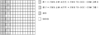
구성 유형 1에 대응하는 첫 번째 Front-Loaded DMRS 구성이 도 1a 및 1b에 도시된다. 이 구성은 단일 사용자 다중 입력 다중 출력(SU-MIMO) 또는 다중 사용자 다중 입력 다중 출력(MU-MIMO)을 위한 최대 8개의 직교 DMRS 포트를 지원하기 위한 것이다. 첫 번째 구성은, 도 1a에 도시된 것처럼, 1-심볼 DMRS가 사용되는 경우에 최대 4개의 직교 DMRS 포트를 지원한다. 특히, 2개의 콤(comb) 및 2개의 순환 시프트(CS)가 최대 4개의 구성요소 세트를 형성하기 위해 조합될 수 있고, 각각의 결과적인 구성요소 세트는 각각 최대 4개의 DMRS 포트에 할당될 수 있다. 이들 구성요소 세트는 본 개시의 맥락에서 CDM 그룹으로도 지칭된다.The first Front-Loaded DMRS configuration corresponding to
도 1b에 도시된 바와 같이, 2개의 심볼 DMRS가 사용되는 경우, 2개의 콤 및 2개의 순환 시프트가 2개의 시분할 직교 커버 코드(TD-OCC), 특히 월시-아다마르(Walsh-Hadamard) TD-OCC {1, 1} 및 {1, -1}과 조합될 수 있고, 최대 8개의 직교 DMRS 포트가 지원될 수 있다. 그러나, 2-심볼 DMRS의 경우, {1, 1} 및 {1, -1} 모두를 사용하지 않고서 최대 4개의 DMRS 포트를 스케줄링하는 것이 가능할 수도 있다.1B, when two symbol DMRSs are used, two combs and two cyclic shifts are two time division orthogonal cover codes (TD-OCC), especially Walsh-Hadamard TD- It can be combined with OCC {1, 1} and {1, -1}, and up to 8 orthogonal DMRS ports can be supported. However, in the case of 2-symbol DMRS, it may be possible to schedule up to 4 DMRS ports without using both {1, 1} and {1, -1}.
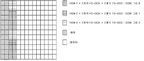
구성 유형 2에 대응하는 두 번째 Front-Loaded DMRS 구성이 도 1c 및 1d에 도시된다. 이 구성은 SU-MIMO 또는 MU-MIMO에 대해 최대 12개의 직교 포트를 지원한다. 특히, 주파수 영역에서 인접한 RE(리소스 요소)에 걸쳐 각각 적용되는 2개의 (월시-아다마르) 주파수 분할 직교 커버 코드(FD-OCC)는 6개의 구성요소 세트 또는 CDM 그룹을 생성한다.A second Front-Loaded DMRS configuration corresponding to
12개의 서브캐리어를 갖는 도 1c 및 1d에서 알 수 있는 바와 같이, 인접한 RE의 페어는 3개의 주파수 분할 다중화(FDM) 그룹으로 그룹화된다. 따라서, 6개의 구성요소 세트는 3개의 FDM 그룹에 각각 적용된 2개의 FD-OCC({1, 1} 및 {1, -1} 모두)로부터 초래된다. 1-심볼 DMRS(도 1c)의 경우, 결과적인 6개의 개별 구성요소 세트는 최대 6개의 직교 DMRS 포트에 할당될 수 있다. 2-심볼 DMRS의 경우, 이들 6개의 구성요소 세트는 2개의 TD-OCC와 더 조합되어 최대 12개의 직교 DMRS 포트를 지원할 수 있다(도 1d).As can be seen in FIGS. 1C and 1D with 12 subcarriers, pairs of adjacent REs are grouped into three frequency division multiplexing (FDM) groups. Thus, the six component set results from two FD-OCCs (both {1, 1} and {1, -1}) applied to three FDM groups respectively. In the case of 1-symbol DMRS (Fig. 1C), the resulting set of 6 individual components can be assigned to up to 6 orthogonal DMRS ports. For 2-symbol DMRS, these six component sets can be further combined with two TD-OCCs to support up to 12 orthogonal DMRS ports (FIG. 1D).
도 1a 내지 1d를 참조하여 상술한 바와 같이, 콤, 순환 시프트, FD-OCC, FDM, 및 TD-OCC는 기준 신호, 특히 Front-Loaded DMRS를 위한 리소스 구성요소를 구성한다.As described above with reference to FIGS. 1A-1D, the comb, cyclic shift, FD-OCC, FDM, and TD-OCC constitute a resource component for a reference signal, particularly Front-Loaded DMRS.
이들 리소스 구성요소는 첫 번째 또는 두 번째 Front-Loaded DMRS 구성에 따라 조합되고, 결과적인 구성요소 세트 또는 CDM 그룹은 각각 직교 DMRS 포트에 할당된다. 그러나, 더 낮은 랭크에서도 2-심볼 DMRS의 사용이 가능하여야 한다. 1-심볼 또는 2-심볼 DMRS의 경우에 특정한 구성에 의해 지원되는 모든 구성요소 세트 또는 CDM 그룹이 포트의 할당에 사용될 필요는 없다. 특히, 2-심볼의 경우에도, {1, 1} 및 {1, -1} 모두를 사용하지 않고서 최대 6개의 DMRS 포트를 스케줄링하는 것이 가능하여야 한다.These resource components are combined according to the first or second Front-Loaded DMRS configuration, and the resulting component set or CDM group is assigned to an orthogonal DMRS port, respectively. However, the use of 2-symbol DMRS should be possible even at lower ranks. In the case of 1-symbol or 2-symbol DMRS, not all component sets or CDM groups supported by a particular configuration need be used for port assignment. In particular, in the case of 2-symbol, it should be possible to schedule up to 6 DMRS ports without using both {1, 1} and {1, -1}.
사용자 장비(UE) 관점에서, 주파수 영역 코드 분할 다중화(CDM)에 의해 다중화된 DMRS 포트는 유사 공존된다(quasi co-located).From a user equipment (UE) perspective, DMRS ports multiplexed by frequency domain code division multiplexing (CDM) are quasi co-located.
그것은 UL 및 DL을 위한 UE에 대한 Front-Loaded DMRS 구성 유형이 상이할 수 있는지 여부에 대한 추가 연구를 위해 여전히 개방되어 있다. 또한, 위의 합의와 관련된 상당한 복잡성/성능 문제가 있는 경우, 다운 선택(down-selection)이 여전히 논의될 수 있다.It is still open for further study as to whether the Front-Loaded DMRS configuration type for UE for UL and DL may be different. Also, if there are significant complexity/performance issues associated with the above agreement, down-selection can still be discussed.
LTE DMRS 구성LTE DMRS configuration
상술한 3GPP NR에서의 DMRS 구성은 월시-아다마르 직교 커버 코드를 사용하는 주파수 및 시간에 있어서의 코드 분할 다중화를 사용하여 최대 총 8개의 직교 포트/계층을 지원하기 위해 다운링크에는 주로 단일 구성이 있는 LTE와는 상이하다. LTE에서의 DMRS 구성에 대한 구성 및 추가 세부사항은 S. Sesia, I. Toufik 및 M. Baker, LTE : The UMTS Long Term Evolution, Second Edition의 섹션 29.1.1에서 확인할 수 있다.The DMRS configuration in the 3GPP NR described above mainly consists of a single configuration in the downlink to support up to a total of 8 orthogonal ports/layers using code division multiplexing in frequency and time using Walsh-Adamar orthogonal cover codes. It is different from LTE. Configuration and additional details on the DMRS configuration in LTE can be found in Section 29.1.1 of S. Sesia, I. Toufik and M. Baker, LTE: The UMTS Long Term Evolution, Second Edition.
3GPP TS 36.212, V14.3.0(표 5.3.3.1.5C-2)로부터 가져온 현재의 LTE에서의 계층 대 포트 매핑의 표는 다음 표 1에 나타내어진다.The table of layer-to-port mapping in current LTE taken from 3GPP TS 36.212, V14.3.0 (Table 5.3.3.1.5C-2) is shown in Table 1 below.

LTE에서는, 다운링크를 위한 최대 8개의 직교 DMRS 포트가 지원되고, 단일 범주의 시간/주파수에 있어서의 다중화 방식인 OCC를 주로 사용한다. 따라서, 특정한 시나리오의 성능에 영향을 주지 않고서 포트 조합 중 하나가 계층을 매핑하기 위해 사용될 수 있다. 또한, 특정한 수의 계층에 대해, 모든 포트 조합에 대한 리소스(DMRS 오버헤드)의 사용은 동일하다.In LTE, up to 8 orthogonal DMRS ports for downlink are supported, and OCC, which is a multiplexing method in a single category of time/frequency, is mainly used. Thus, one of the port combinations can be used to map the layers without affecting the performance of a particular scenario. Also, for a certain number of layers, the use of resources (DMRS overhead) for all port combinations is the same.
또한, LTE는 MU-MIMO에 대한 제한된 지원을 제공한다. 또한, 고정된 DMRS 구성이 지원되고, 따라서 동적 구성에 추가적인 시그널링이 필요하지 않다.In addition, LTE provides limited support for MU-MIMO. In addition, a fixed DMRS configuration is supported, so additional signaling is not required for dynamic configuration.
표 1로부터 알 수 있는 바와 같이, LTE에서 계층 대 포트 매핑에 허용된 조합은 매우 제한되어 있다. 길이 4 비트맵은 특정한 사용자에 대한 계층 대 포트 매핑을 시그널링하기 위해 정의된다. 다음과 같은 제한으로 계층 대 포트 매핑 결과에 대해 최소 개수의 포트 조합이 지원된다. 최대 2개 계층의 경우, 매핑을 위한 포트 인덱싱은 연속적이고 중첩되지 않는다. 3개 내지 8개 계층의 경우, 인덱싱은 연속적이고 중첩되지 않으며, 고정된 시작점으로서의 인덱스 0으로부터 시작한다. 매핑은 하나의 포트 조합으로 제한된다.As can be seen from Table 1, the combinations allowed for layer-to-port mapping in LTE are very limited. The
LTE의 최신 릴리스에서는, 투과적인 MU-MIMO만 지원된다(비 투과적인 MU-MIMO는 지원되지 않는다). 그러나, 항상 그런 것은 아니었다.In the latest release of LTE, only transparent MU-MIMO is supported (non-transparent MU-MIMO is not supported). However, this was not always the case.
LTE Rel-8에서, MU-MIMO가 최대 2개의 UE 송신을 지원하기 위해 처음으로 도입되었을 때, 1비트 전용 전력 오프셋 필드를 가짐으로써 비 투과적인 MU-MIMO가 도입되었다. 그러나, 2개보다 많은 UE에 대한 비 투과적인 MU-MIMO에 대한 지원은 결코 합의되지 않았고, 특히 LTE의 이후 릴리스에서 그렇다. 증가된 시그널링 오버헤드의 단점은 그로 인한 이득을 초과하지 않기로 결정되었다.In LTE Rel-8, when MU-MIMO was first introduced to support transmission of up to 2 UEs, non-transparent MU-MIMO was introduced by having a 1-bit dedicated power offset field. However, support for non-transparent MU-MIMO for more than two UEs has never been agreed, especially in later releases of LTE. The disadvantage of the increased signaling overhead was decided not to exceed the resulting gain.
NR에 대한 DMRS 요구사항DMRS requirements for NR
LTE의 계층 대 포트 매핑에 대한 제한은 더 이상 3GPP NR에서 견딜 수 없다. 특히, 3GPP NR에서 새로운 시스템 설계의 이점으로부터 이득을 얻기 위해 비 투과적인 MU-MIMO에 대한 요구가 있다.LTE's restrictions on layer-to-port mapping can no longer be tolerated in 3GPP NR. In particular, there is a need for non-transparent MU-MIMO to benefit from the benefits of new system design in 3GPP NR.
예컨대, 비 투과적인 MU-MIMO의 지원을 3GPP NR에 통합하기 위해, 전용 비트 필드를 포함하지 않는 LTE에 대한 결정을 다시 검토하는 것이 가능할 것이다. 그러나, 현재의 고려사항에서도, MU-MIMO를 위한 전용 비트 필드가 존재하기 때문에, 지원은 필요하지 않다.For example, in order to incorporate support of non-transparent MU-MIMO into 3GPP NR, it would be possible to review the decision for LTE that does not include a dedicated bit field. However, even with current considerations, support is not required since there is a dedicated bit field for MU-MIMO.
실시예의 설명Description of Examples
본 개시는 데이터가 다수의 안테나를 사용하여 계층에서 송신 및/또는 수신되는 이동 통신 시스템에서 코드 분할 다중화(CDM) 그룹 단위로 공동 스케줄링 정보의 시그널링(비 투과적인 MU-MIMO)을 가능하게 한다. 보다 구체적으로, 본 개시는 보다 효율적이고 효과적인 시그널링 메커니즘을 가능하게 하기 위해 공동 스케줄링 정보와 조합되는 계층 대 포트(layer-to-port) 매핑 조합 정보의 세트를 제안한다.The present disclosure enables signaling (non-transparent MU-MIMO) of co-scheduling information in units of code division multiplexing (CDM) in a mobile communication system in which data is transmitted and/or received at a layer using multiple antennas. More specifically, the present disclosure proposes a set of layer-to-port mapping combination information combined with joint scheduling information to enable a more efficient and effective signaling mechanism.
예시적인 실시예에서, 도 2에 도시된 바와 같이, 본 개시는 이동 통신 시스템에서 다수의 안테나를 사용하는 기지국(260)과의 사이에서 데이터를 송신 및/또는 수신하기 위한 이동 단말(210)을 제공한다. 이동 단말(210) 및 기지국(260)은 무선 채널(250)을 통해 데이터를 송신 및/또는 수신하도록 구성된다.In an exemplary embodiment, as shown in FIG. 2, the present disclosure provides a
이동 단말(210)은 일반적으로 LTE 및 NR에서 명명된 사용자 장비(UE)에 대응할 수 있고, 기지국(260)은 일반적으로 LTE 및 NR에서 명명된 진화된 NodeB(eNodeB 또는 eNB) 또는 차세대 NodeB(gNodeB 또는 gNB)에 대응할 수 있다.The
보다 구체적으로, 이동 단말(210)은 기지국(260)과의 사이에서 데이터를 계층에서 송신 및/또는 수신하도록 구성된다. 상술한 바와 같이, 계층(또는 공간 계층)이라는 용어는 공간 다중화에 의해 생성된 후 상이한 안테나 포트를 통해 이동 단말(210)과 기지국(260) 사이에서 교환되는 상이한 스트림 중 하나를 지칭한다.More specifically, the
송신 및 (그 후에) 수신된 데이터의 응집 복조(coherent demodulation)를 위해, 기준 신호도 이동 단말(210)과 기지국(260) 사이에서 교환된다. 상술한 바와 같이, 기준 신호의 송신 및/또는 수신은 계층 대 포트 매핑을 참조하여 수행된다. 이 매핑은 각 계층 각각에 대해 기준 신호를 송신/수신하는데 사용될 하나의 DMRS 포트를 지정한다.For coherent demodulation of the transmitted and (after) received data, a reference signal is also exchanged between the
특히, 계층 대 포트 매핑은 기지국(260) 및 이동 단말(210)의 구성, 즉 DMRS 구성 유형(예컨대, DMRS 구성 유형 1 또는 2) 및 DMRS에 사용될 심볼의 수(예컨대, 1-심볼 또는 2-심볼 DMRS)에 의해 특정되는 구성에 따라 변한다. 상술한 바와 같이, 이 구성은 DMRS가 반송되는 리소스뿐만 아니라 기지국(260)에 의해 스케줄링될 수 있는 DMRS 포트의 최대 수를 결정한다.In particular, the layer-to-port mapping consists of the
다시 말해서, 이동 단말(210) 및 기지국(260)은 이동 통신 시스템에서 통신하기 위해 복수의 구성 중 어느 것이 선택되는지에 따라 상이한 계층 대 포트 매핑으로 되돌아간다. DMRS 포트의 구성은 기지국(260) 및 이동 단말이 데이터 송신 및/또는 수신을 수행하기 위해 계층 대 포트 매핑을 이용할 수 있도록 특정된다.In other words, the
이를 위해, 이동 단말(210)은, 동작 중에, 기준 신호를 반송하기 위한 각각의 (시간-주파수) 리소스를 DMRS 포트에 할당하기 위한 구성을 정의하는 파라미터를 수신하는 회로, 예컨대 송수신기(220)와 프로세서(230)를 포함한다. 다시 말해서, 그 구성은 하나 이상의 DMRS 포트의 기준 신호의 각각을 (리소스) 구성요소 세트로도 지칭될 수 있는 특정한 리소스에 할당한다.To this end, the
리소스 또는 (리소스) 구성요소 세트는 복수의 코드 분할 다중화(CDM) 그룹으로 그룹화된다. 특히, 코드 분할 다중화(CDM) 그룹은 각 DMRS 포트에 대해 기준 신호가 반송되는 리소스 또는 (리소스) 구성요소 세트를 지정하여, 각 리소스 또는 (리소스) 구성요소 세트 상에서, 동일한 CDM 그룹의 각각의 DMRS 포트에서 최대 개수 2개 또는 4개의 직교 기준 신호가 반송될 수 있다.Resource or (resource) component sets are grouped into a plurality of code division multiplexing (CDM) groups. Specifically, a code division multiplexing (CDM) group designates a resource or (resource) component set for which a reference signal is carried for each DMRS port, so that each DMRS of the same CDM group on each resource or (resource) component set. Up to two or four orthogonal reference signals may be carried in the port.
도 1a에 도시된 예를 참조하면, 각각 2개의 순환 시프트(2개의 상이한 DMRS 포트의 세트를 초래함)를 갖는 2개의 콤(콤 1, 콤 2)의 리소스는 별도의 CDM 그룹(CDM 그룹 0, CDM 그룹 1)을 정의하고 있다. 도 1b에 도시된 예의 경우, 각각 2개의 순환 시프트 및 2개의 TD-OCC(4개의 상이한 DMRS 포트의 세트를 초래함)를 갖는 2개의 콤(콤 1, 콤 2)의 리소스는 별도의 CDM 그룹(CDM 그룹 0, CDM 그룹 1)을 정의하고 있다.Referring to the example shown in FIG. 1A, the resources of two combs (
또한, 도 1c에 도시된 예의 경우, 각각 2개의 FD-OCC(2개의 상이한 DMRS 포트의 세트를 초래함)를 갖는 3개의 FDM 그룹(FDM 1, FDM 2, FDM 3)의 리소스는 별도의 CDM 그룹(CDM 그룹 0, CDM 그룹 1, CDM 그룹 2)을 정의하고 있다. 마지막으로, 도 1d에 도시된 예의 경우, 각각 2개의 FD-OCC 및 2개의 TD-OCC(4개의 상이한 DMRS 포트의 세트를 초래함)를 갖는 3개의 FDM 그룹(FDM 1, FDM 2, FDM 3)의 리소스는 별도의 CDM 그룹(CDM 그룹 0, CDM 그룹 1, CDM 그룹 2)을 정의하고 있다.In addition, in the example shown in FIG. 1C, the resources of three FDM groups (
상술한 바와 같이, 기준 신호를 반송하기 위한 (시간-주파수) 리소스는 복수의 코드 분할 다중화(CDM) 그룹으로 그룹화된다. 특히, 본 개시의 맥락에서, CDM 그룹은 동일한 리소스를 사용하고 시간 및/또는 주파수에 있어서 직교 커버 코드(OCC) 또는 코드 분할 다중화(CDM)를 사용함으로써 서로 직교하는 DMRS 포트의 세트를 지칭한다.As described above, (time-frequency) resources for carrying a reference signal are grouped into a plurality of code division multiplexing (CDM) groups. In particular, in the context of the present disclosure, a CDM group refers to a set of DMRS ports that are orthogonal to each other by using the same resources and using orthogonal cover codes (OCC) or code division multiplexing (CDM) in time and/or frequency.
본 개시의 맥락에서, 이동 단말(210)의 관점에서 CDM 그룹에 대한 참조가 이루어진다. 이동 단말(210)의 경우, CDM 그룹은 유사 공존되는 DMRS 포트의 리소스 또는 (리소스) 구성요소 세트를 지칭한다.In the context of the present disclosure, reference is made to the CDM group from the perspective of the
다시 예시적인 실시예로 돌아가면, 이동 단말(210)의 회로, 예컨대 송수신기(220)와 프로세서(230)는, 동작 중에, 데이터 송신 및/또는 수신을 위한 적어도 하나의 CDM 그룹의 DMRS 포트에서 기준 신호를 배열하기 위해 적용될 계층 대 포트 매핑 조합의 세트 중 하나를 나타내는 제어 정보를 수신한다.Returning to the exemplary embodiment again, the circuitry of the
그 후, 이동 단말(210)은 DMRS 포트(들)를 결정하고, 리소스 또는 (리소스) 구성요소 세트의 구성에 기초하여, 이 DMRS 포트(들)를 위해 데이터 송신 및/또는 수신을 위한 각각의 리소스를 결정하기 위해, 계층 대 포트 매핑 조합의 세트 중 표시된 하나를 이용할 수 있다. 다시 말해서, 구성과 표시된 계층 대 포트 매핑을 조합해야만 데이터 송신 및/또는 수신을 허용한다.Thereafter, the
그러나, 구성 파라미터 및 제어 정보 모두는 동시에 이동 단말(210)에 의해 수신되지 않는다. 오히려, 기지국(260)은, 예컨대 무선 리소스 제어(RRC) 프로토콜을 통해, 구성 파라미터를 드물게 시그널링할 수 있는 반면, 제어 정보는 물리 다운링크 제어 채널(PDCCH)을 통해 다운링크 제어 정보(DCI)에서 스케줄링 정보와 함께 시그널링될 수 있다.However, both configuration parameters and control information are not simultaneously received by the
그러나, 예시적인 실시예에 덧붙여, 수신된 제어 정보는 계층 대 포트 매핑 구성의 세트 중 하나를 이동 단말(210)에 표시하는 것만으로 제한되지 않는다. 오히려, 수신된 제어 정보는 추가적으로 CDM 그룹 단위로 공동 스케줄링 정보를 이동 단말(210)에 표시한다.However, in addition to the exemplary embodiment, the received control information is not limited to simply displaying one of the set of layer-to-port mapping configurations to the
그 후, 이 공동 스케줄링 정보는 동일한 데이터 송신 및/또는 수신에, 즉 동일한 TTI의 데이터 송신 및/또는 수신을 위한 간섭 제거 및/또는 레이트 매칭을 개선하기 위해 이용될 수 있다.This co-scheduling information can then be used to improve interference cancellation and/or rate matching for the same data transmission and/or reception, ie for data transmission and/or reception of the same TTI.
CDM 그룹 단위로 공동 스케줄링 정보를 표시하는 것은 비 투과적인 MU-MIMO 시그널링에 유리한 트레이드오프를 제공한다. 특히, CDM 그룹 단위로 공동 스케줄링을 표시하는 것은 개선된 간섭 제거 및/또는 데이터 송신 용량을 증가시키기 위한 레이트 매칭의 적응에 대하여 시그널링 오버헤드를 최소화하는 이점을 달성한다.Displaying co-scheduling information on a CDM group basis provides a favorable tradeoff for non-transparent MU-MIMO signaling. In particular, indicating co-scheduling on a CDM group basis achieves the advantage of minimizing signaling overhead for improved interference cancellation and/or adaptation of rate matching to increase data transmission capacity.
이하에서는, 이동 단말(210)이 기준 신호 송신 및/또는 수신을 수행하도록 스케줄링되는 CDM 그룹(들)(이하, 제 1 세트의 CDM 그룹으로 지칭됨)에 대한 공동 스케줄링 정보의 표시와 이동 단말(210)에 대해 스케줄링되지 않는 다른 CDM 그룹(들)(제 2 세트의 CDM 그룹으로 지칭됨) 사이에서 구별이 이루어진다. 그러나, 이 구별은 공동 스케줄링 정보에 기인하는 이점을 고려하면 훨씬 더 명백해진다.Hereinafter, the
상술한 바와 같이, 이동 단말(210)은 개선된 간섭 제거를 위해 공동 스케줄링 표시를 사용할 수 있다.As described above, the
각각의 CDM 그룹에서, 기지국은 (동일한 CDM 그룹의) 동일한 리소스 상에서 DMRS 포트에 기준 신호를 할당하기 위해 상이한 이동 단말을 공동 스케줄링할 수 있다. CDM 그룹에서 DMRS 포트가 서로 직교한다고 하더라도, 기준 신호 사이에 누설 영향이 존재하여 기준 신호의 수신 품질이 저하될 수 있다. 따라서, 이 간섭은 데이터 송신 및/또는 수신을 위한 더 낮은 응집 복조 능력을 야기할 수 있다.In each CDM group, the base station can co-schedule different mobile terminals to assign a reference signal to the DMRS port on the same resource (of the same CDM group). Even if the DMRS ports are orthogonal to each other in the CDM group, there is a leakage effect between the reference signals and the reception quality of the reference signal may deteriorate. Thus, this interference may result in lower coherent demodulation capability for data transmission and/or reception.
이제, CDM 그룹 단위로 추가적인 공동 스케줄링 정보를 이용하여, 이동 단말은 CDM 그룹(들), 즉 "자신의" 기준 신호도 반송하고 있는 리소스에 대한 공동 스케줄링을 인식하고 있다. 따라서, 이 추가적인 공동 스케줄링 정보를 이용하여, 이동 단말은 기준 신호에 대한 간섭 제거를 수행하여, 응집 복조 능력을 향상시킬 수 있다.Now, using additional co-scheduling information on a CDM group basis, the mobile terminal is aware of the co-scheduling of the CDM group(s), ie, resources that are also carrying “own” reference signals. Therefore, by using this additional joint scheduling information, the mobile terminal can perform interference cancellation on the reference signal, thereby improving cohesive demodulation capability.
그러나, 특히, 개선된 간섭 제거는 이동 단말(210)이 기준 신호 송신 및/또는 수신을 수행하도록 스케줄링되는 CDM 그룹(들)(제 1 세트의 CDM 그룹)에서의 공동 스케줄링 정보와 관련된다.However, in particular, improved interference cancellation relates to co-scheduling information in the CDM group(s) (first set of CDM groups) in which the
또한, 이동 단말(210)은 개선된 레이트 매칭을 위해 공동 스케줄링된 표시를 사용할 수 있다.In addition, the
각각의 CDM 그룹에서, 기지국은 (예컨대, 상이한 CDM 그룹의) 상이한 리소스 상에서 DMRS 포트에 기준 신호를 할당하도록 상이한 이동 단말을 스케줄링할 수 있다. 상이한 CDM 그룹의 DMRS 포트의 스케줄링이 그들의 간섭 특성과 관련하여 최적이라 하더라도, 이 스케줄링은 이동 단말이 데이터의 송신 및/또는 수신을 위해 (전후관계를 무시하고) 상이한 리소스를 재사용하는 것을 차단한다.In each CDM group, the base station can schedule different mobile terminals to assign a reference signal to the DMRS port on different resources (eg, of different CDM groups). Although scheduling of DMRS ports of different CDM groups is optimal with respect to their interference characteristics, this scheduling prevents the mobile terminal from reusing different resources (ignoring the context) for transmission and/or reception of data.
다시 말해서, (상이한 CDM 그룹의) 상이한 리소스에 대한 기준 신호의 (실제) 할당에 관한 정보는 데이터 송신 및/또는 수신을 반송하는 심볼을 (상이한 CDM 그룹의) 이 (추가적인) 상이한 리소스에 할당하기로 결정할 수 있는 위치에 이동 단말을 놓는다. 이것이 각각의 TTI에서 데이터 송신 용량을 증가시킨다는 것은 말할 것도 없고, 따라서 데이터 송신 용량의 증가를 이용하기 위해 적응된 레이트 매칭을 필요하게 만든다.In other words, the information about the (real) allocation of the reference signal to different resources (of different CDM groups) is to allocate symbols carrying data transmission and/or reception to different (additional) different resources (of different CDM groups). Place the mobile terminal in a location that can be determined by. Not to mention that this increases the data transmission capacity in each TTI, thus making it necessary to adapt the rate matching to take advantage of the increase in data transmission capacity.
이제, CDM 그룹 단위로 추가적인 공동 스케줄링 정보를 이용하여, 이동 단말은 상이한 CDM 그룹(들), 즉 "자신의" 기준 신호를 반송하고 있지 않은 리소스에 대한 공동 스케줄링을 인식하고 있다. 이 추가적인 공동 스케줄링 정보를 이용하여, 이동 단말은 데이터 송신 및/또는 수신을 위해 상이한 CDM 그룹(들)으로부터 이들 리소스를 재사용할 수 있는지 여부를 결정할 수 있지만, 데이터 송신 용량의 증가에 따라 적응된 레이트 매칭을 필요로 한다.Now, using additional co-scheduling information on a CDM group basis, the mobile terminal is aware of co-scheduling for different CDM group(s), ie, resources that are not carrying a "own" reference signal. Using this additional co-scheduling information, the mobile terminal can determine whether these resources can be reused from different CDM group(s) for data transmission and/or reception, but the rate adapted as the data transmission capacity increases. Matching is required.
하지만, 특히, 동일한 TTI의 데이터 송신 및/또는 수신을 위한 개선된 레이트 매칭은 이동 단말이 기준 신호 송신 및/또는 수신을 수행하도록 스케줄링되지 않는 상이한 CDM 그룹(들)(제 2 세트의 CDM 그룹)에서의 공동 스케줄링 정보와 관련될 뿐이다.However, in particular, the improved rate matching for data transmission and/or reception of the same TTI is different CDM group(s) (the second set of CDM groups) in which the mobile terminal is not scheduled to perform reference signal transmission and/or reception. It is only related to the co-scheduling information in.
하지만, 요약하면, 데이터 송신 용량을 증가시키기 위한, CDM 그룹 단위로 공동 스케줄링 정보의 존재와 결부되는 개선된 간섭 제거 및 레이트 매칭 적응의 이점은 이동 단말이 기준 신호 송신을 수행하도록 스케줄링되는 CDM 그룹(들)(제 1 세트의 CDM 그룹) 또는 그렇지 않은 CDM 그룹(들)(제 2 세트의 CDM 그룹)에 대해 공동 스케줄링이 표시되는지 여부에 의존할 수 있다.In summary, however, the advantage of improved interference cancellation and rate matching adaptation associated with the presence of co-scheduling information on a CDM group basis, to increase data transmission capacity, is that the CDM group is scheduled for the mobile terminal to perform reference signal transmission ( S) (first set of CDM groups) or otherwise CDM group(s) (second set of CDM groups) may depend on whether joint scheduling is indicated.
따라서, 공동 스케줄링 정보의 표시가 복수의 CDM 그룹의 전부가 아닌 부분집합에 대해서만 시그널링되는 경우에도 이미 유리한 효과를 제공한다는 것이 이미 이 개시로부터 명백하다.Therefore, it is already apparent from this disclosure that even if the indication of the co-scheduling information is signaled only for a subset rather than all of a plurality of CDM groups.
본 개시의 맥락에서, 공동 스케줄링 정보는 CDM 그룹 단위로 시그널링된다. 이 공동 스케줄링 정보는 기지국이 기준 신호 송신 및/또는 수신을 위해 각 CDM 그룹의 각 리소스의 DMRS 포트에서 상이한 이동 단말을 공동 스케줄링하고 있다고 하는 이동 단말에 대한 표시로서 이해되어야 한다.In the context of the present disclosure, co-scheduling information is signaled on a CDM group basis. This joint scheduling information should be understood as an indication to the mobile terminal that the base station is co-scheduling different mobile terminals at the DMRS port of each resource of each CDM group for transmitting and/or receiving reference signals.
공동 스케줄링 정보가 제공되는 CDM 그룹에 따라, 공동 스케줄링 정보를 상이하게 해석하는 것이 유리할 수 있다.Depending on the CDM group to which the co-scheduling information is provided, it may be advantageous to interpret the co-scheduling information differently.
제 2 세트의 CDM 그룹과 관련하여, 공동 스케줄링 정보는 이동 단말로 하여금 데이터 송신 용량의 증가로부터 이익을 얻도록 레이트 매칭을 적응시키게 한다. 특히, 이를 위해, 상이한 CDM 그룹(들)의 DMRS 포트에 할당된 적어도 하나의 상이한 이동 단말이 존재하는지(또는 그렇지 않은지)는 이동 단말만이 알 필요가 있다.With respect to the second set of CDM groups, the co-scheduling information allows the mobile terminal to adapt rate matching to benefit from an increase in data transmission capacity. In particular, for this purpose, only the mobile terminal needs to know if there is (or is not) at least one different mobile terminal assigned to the DMRS port of the different CDM group(s).
제 2 세트의 CDM 그룹 중 하나에서 적어도 하나의 DMRS 포트가 할당되면, 각각의 기준 신호 송신 및/또는 수신은 레이트 매칭의 적응 및 데이터 송신 용량의 증가에 따른 이득보다 더 중요한 것으로 간주된다. 그렇지 않으면, 이동 단말은 데이터 송신 용량의 증가를 이용하기 위해 레이트 매칭을 적응시킬 수 있다.If at least one DMRS port is assigned in one of the second set of CDM groups, each reference signal transmission and/or reception is considered more important than the gain due to adaptation of rate matching and an increase in data transmission capacity. Otherwise, the mobile terminal can adapt rate matching to take advantage of the increase in data transmission capacity.
따라서, 제 2 세트의 CDM 그룹에 대해, 공동 스케줄링 정보는 CDM 그룹마다 스케줄링되는 "적어도 하나의" 상이한 이동 단말을 나타내는 것으로 해석될 수 있다.Thus, for the second set of CDM groups, the co-scheduling information can be interpreted as representing “at least one” different mobile terminal that is scheduled for each CDM group.
제 1 세트의 CDM 그룹과 관련하여, 공동 스케줄링 정보는 이동 단말로 하여금 개선된 간섭 제거로부터 이익을 얻을 수 있게 한다. 그러나, 개선된 간섭 제거는 제 1 세트의 동일한 CDM 그룹의 상이한 DMRS 포트가 할당된 특정한 수(도 3 내지 6에서 수 X로 표시됨)보다 많은, 즉 1개보다 많은(예컨대, 2개 또는 3개) 이동 단말이 존재하는 경우에만 필요하게 될 수 있다.With regard to the first set of CDM groups, the co-scheduling information enables the mobile terminal to benefit from improved interference cancellation. However, the improved interference cancellation is greater than a specific number (denoted by the number X in Figures 3-6) of different DMRS ports of the same CDM group of the first set, i.e. more than 1 (e.g., 2 or 3) ) It may be necessary only when a mobile terminal exists.
대신, 특정한 수보다 적은 수, 즉 1개 또는 0개의 이동 단말이 제 1 세트의 동일한 CDM 그룹의 상이한 DMRS 포트에 할당되면, 기존 메커니즘이 직교 DMRS 포트를 확립하기에 충분하게 동작하고 있는 것으로 충분히 기대될 수 있다.Instead, if less than a certain number, i.e., 1 or 0 mobile terminals are assigned to different DMRS ports of the same CDM group in the first set, it is sufficiently expected that the existing mechanism is operating sufficiently to establish an orthogonal DMRS port. Can be.
예컨대, 3GPP NR 배치 시나리오에서, 기준 신호의 수신기에서 블라인드 간섭 검출 메커니즘을 이용함으로써 간섭 제거가 개선된다. 이에 의해, 수신기에서의 간섭에 대한 사전 지식 없이(공유 스케줄링 정보는 특정한 수, 즉 2개 또는 3개의 이동 단말로부터의 간섭이 존재하는 것만을 나타냄) 기준 신호의 수신 특성의 개선이 달성된다.For example, in a 3GPP NR deployment scenario, interference cancellation is improved by using a blind interference detection mechanism at the receiver of the reference signal. By this, improvement in the reception characteristics of the reference signal is achieved without prior knowledge of interference at the receiver (the shared scheduling information only indicates that there is interference from a certain number, i.e., two or three mobile terminals).
하지만, 블라인드 간섭 검출 메커니즘은 계산적으로 복잡하고, 전력 소비에 비용이 많이 들고, 시그널링 흐름에 무시할 수 없는 양의 처리 지연을 유발하기 때문에, 이는 (실제로) 많은 양의 간섭이 표시되는 경우에만 유리하다. 이를 위해, 제 1 세트의 CDM 그룹에서 공동 스케줄링 간섭이 표시되는 수(도 3 내지 6에서 수 X로 표시됨)는 제 2 세트의 CDM 그룹에서 공동 스케줄링 간섭이 표시되는 수와 상이하다.However, since blind interference detection mechanisms are computationally complex, costly to consume power, and cause a negligible amount of processing delay in the signaling flow, this is only advantageous when (in practice) a large amount of interference is indicated. . To this end, the number in which co-scheduling interference is indicated in the first set of CDM groups (indicated by the number X in FIGS. 3 to 6) is different from the number in which co-scheduling interference is indicated in the second set of CDM groups.
다시 말해서, 공동 스케줄링 정보의 해석은 그것이 수신되는 CDM 그룹 및 CDM 그룹의 세트에 의존할 수 있다. "자신의" 기준 신호가 반송되는 제 1 세트의 CDM 그룹에 대해 수신되는 경우, 공동 스케줄링 정보는 제 2 세트의 CDM 그룹과 비교하여 CDM 그룹마다 특정한 수의 공동 스케줄링된 이동 단말의 존재를 나타낼 수 있고, 여기서 공동 스케줄링 정보는 CDM 그룹마다 임의의 공동 스케줄링된 이동 단말의 존재를 나타낼 수 있다.In other words, the interpretation of the co-scheduling information may depend on the CDM group and set of CDM groups from which it is received. When the "own" reference signal is received for the first set of CDM groups carried, the co-scheduling information may indicate the presence of a specific number of co-scheduled mobile terminals for each CDM group as compared to the second set of CDM groups. Here, the co-scheduling information may indicate the presence of any co-scheduled mobile terminal for each CDM group.
상기와 유사하게, 본 개시는 이동 통신 시스템에서 다수의 안테나를 사용하는 이동 단말(210)과의 사이에서 데이터를 송신 및/또는 수신하기 위한 기지국(260)을 또한 제공한다. 또한 여기서 기지국(260) 및 이동 단말(210)은 무선 채널(250)을 통해 데이터를 송신 및/또는 수신하도록 구성된다.Similar to the above, the present disclosure also provides a
기지국(260)은, 동작 중에, 기준 신호를 반송하기 위한 복수의 코드 분할 다중화(CDM) 그룹으로 그룹화되는 리소스 각각을 포트에 할당하기 위한 구성을 정의하는 파라미터를 이동 단말(210)에 송신하고, 데이터 송신 및/또는 수신을 위해 적어도 하나의 CDM 그룹의 포트에서 기준 신호를 배열하기 위해 적용될 계층 대 포트 매핑 조합의 세트 중 하나를 나타내는 제어 정보를 이동 단말(210)에 송신하는 회로, 예컨대 송수신기(270) 및 프로세서(280)를 포함한다.During operation, the
또한, 여기서 제어 정보는 동일한 데이터 송신 및/또는 수신을 위해 복수의 CDM 그룹 중 적어도 하나의 CDM 그룹 및/또는 적어도 상이한 CDM 그룹에 대한 공동 스케줄링 정보를 표시하고 있다.In addition, the control information indicates co-scheduling information for at least one CDM group and/or at least different CDM groups among a plurality of CDM groups for transmitting and/or receiving the same data.
제어 정보가 기지국(260)과 이동 단말(210) 사이에서 통신되는 형태를 이하 참조한다. 이를 위해, 시그널링 메커니즘의 예시적인 구현으로서 도 3 내지 6에 대한 참조가 이루어진다.The form in which control information is communicated between the
이미 상술한 바와 같이, 제어 정보(각 도면의 1열)는 계층 대 포트 매핑 구성의 세트(각 도면의 2열 및 3열) 중 하나를 이동 단말(210)에 표시할 뿐만 아니라, CDM 그룹 단위로 공동 스케줄링 정보(각 도면의 4열 및 5열 또는 4열 내지 6열)를 이동 단말(210)에 표시하도록 구성된다.As already described above, the control information (
이와 관련하여, 예컨대 이진 형태로 제어 정보를 수신한 이동 단말(210)은 (각 도면의 1열에서의) 대응하는 인덱스를 갖는 행을 참조하여, 기지국에 의해 표시되고 있는 계층 대 포트 매핑 및 각각의 CDM 그룹에 대한 공동 스케줄링 정보를 얻는다. 도면에서 알 수 있는 바와 같이, 제어 정보가 공동 스케줄링 정보의 모든 가능한 순열을 반영하기 위해 동일한 포트 대 계층 매핑을 갖는 별개의(다수의) 행을 허용하는 것이 제안된다.In this regard, for example, the
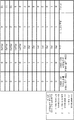
보다 상세하게, 도 3은 DMRS 구성 유형 1 및 1-심볼 DMRS 구성에 대해 CDM 그룹 단위로 공동 스케줄링 정보(4열 및 5열)와 조합되는 계층 대 포트 매핑 조합의 예시적인 세트(2열 및 3열)를 나타낸다. 따라서, 이 예는 도 1a에 도시된 바와 같이 리소스에 DMRS 포트를 할당하는 것에 기초하고, 여기서 총 2개의 DMRS 포트가 2개의 CDM 그룹 각각에서 스케줄링될 수 있다.More specifically, FIG. 3 is an exemplary set of layer-to-port mapping combinations (
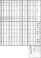
유사하게, 도 4는 DMRS 구성 유형 1 및 2-심볼 DMRS 구성에 대해 CDM 그룹 단위로 공동 스케줄링 정보(4열 및 5열)와 조합되는 계층 대 포트 매핑 조합의 예시적인 세트(2열 및 3열)를 나타낸다. 따라서, 이 예는 도 1b에 도시된 바와 같이 리소스에 DMRS 포트를 할당하는 것에 기초하고, 여기서 총 4개의 DMRS 포트가 2개의 CDM 그룹 각각에서 할당될 수 있다.Similarly, FIG. 4 is an exemplary set of layer-to-port mapping combinations (
또한, 도 5는 DMRS 구성 유형 2 및 1-심볼 DMRS의 경우에 CDM 그룹 단위로 공동 스케줄링 정보(4열 내지 6열)와 조합되는 계층 대 포트 매핑 조합의 예시적인 세트(2열 및 3열)를 나타낸다. 따라서, 이 예는 도 1c에 도시된 바와 같이 리소스에 DMRS 포트를 할당하는 것에 기초하고, 여기서 총 2개의 DMRS 포트가 3개의 CDM 그룹 각각에서 할당될 수 있다.5 is an exemplary set of layer-to-port mapping combinations (
또한, 도 6a 및 6b는 DMRS 구성 유형 2 및 2-심볼 DMRS의 경우에 CDM 그룹 단위로 공동 스케줄링 정보(4열 내지 6열)와 조합되는 계층 대 포트 매핑 조합의 예시적인 세트(2열 및 3열)를 나타낸다. 따라서, 이 예는 도 1d에 도시된 바와 같이 리소스에 DMRS 포트를 할당하는 것에 기초하고, 여기서 총 4개의 DMRS 포트가 3개의 CDM 그룹 각각에서 스케줄링될 수 있다.6A and 6B are exemplary sets of layer-to-port mapping combinations (
도 3 내지 6의 모든 예시적인 구현에 대해, CDM 그룹 및 DMRS 포트가 다음과 같은 방식으로 인덱싱되는 것으로 가정된다.For all the exemplary implementations of Figures 3-6, it is assumed that the CDM group and DMRS ports are indexed in the following manner.
1. CDM 그룹은 연속적으로 인덱싱되고, CDM 그룹의 DMRS 포트는 (또한) 연속적으로, 즉 DMRS 포트의 인덱스가 복수의 CDM 그룹의 인덱스와 함께 증가하도록 인덱싱된다.1. The CDM groups are indexed consecutively, and the DMRS ports of the CDM groups are (continuously) indexed so that the indexes of the DMRS ports increase with the indexes of the multiple CDM groups.
다시 말해, (단일) CDM 그룹을 고려할 때, 이 CDM 그룹의 DMRS 포트의 인덱스는 연속적으로 분배된다. 이것은 특정한 CDM 그룹에 관계없이 각 CDM 그룹에 대한 DMRS 포트가 연속적으로 인덱싱된다는 사실에서 이미 유추될 수 있다.In other words, when considering a (single) CDM group, the index of the DMRS port of this CDM group is continuously distributed. This can already be deduced from the fact that the DMRS ports for each CDM group are indexed consecutively, regardless of the particular CDM group.
이제 별개의 CDM 그룹을 고려하면, DMRS 포트의 인덱스는 CDM 그룹으로 분배되어, 인덱스가 더 낮은 특정한 CDM 그룹의 DMRS 포트(들) 중 어느 하나가 다음의 더 높은 인덱스를 갖는 다른 특정한 CDM 그룹의 DMRS 포트(들) 중 어느 하나보다 낮은 인덱스를 갖는다.Now considering a separate CDM group, the index of the DMRS port is distributed to the CDM group, so that any one of the DMRS port(s) of the specific CDM group with the lower index has the next higher index and the DMRS of the other specific CDM group. It has an index lower than any of the port(s).
CDM 그룹 및 DMRS 포트의 인덱싱을 연속적인 방식으로 지정하면, 도 3 내지 6의 예시적인 구현과 관련하여, 기지국이 복수의 CDM 그룹 전체에 걸쳐 연속적으로 그리고 점차적으로(또는 순차적으로) DMRS 포트를 이동 단말에 할당하고 있다고 또한 가정된다.If the indexing of the CDM group and DMRS ports is specified in a continuous manner, with respect to the exemplary implementations of FIGS. 3 to 6, the base station moves the DMRS ports continuously and gradually (or sequentially) across a plurality of CDM groups. It is also assumed that it is assigned to the terminal.
2. 이동 단말은 가장 낮은 인덱스를 갖는 DMRS 포트로 시작하는 연속적인 인덱스를 갖는 복수의 CDM 그룹 모두로부터 DMRS 포트가 할당된다.2. The mobile terminal is assigned DMRS ports from all of a plurality of CDM groups having consecutive indexes starting with the DMRS port having the lowest index.
논의의 편의상, 기지국(260)이 가장 낮은 인덱스를 갖는 DMRS 포트(DMRS 포트 0, 또는 P0)를 이동 단말(210)에 할당한다고 가정한다. 그러면, 기지국(260)이 다른 DMRS 포트를 동일한 이동 단말(210)에 할당하고자 한다면, 다음의 더 높은 연속적인 인덱스를 갖는 DMRS 포트(DMRS 포트 1, 또는 P1) 할당을 진행해야 한다. 따라서, 하나의 이동 단말에 연속적인 인덱스를 갖지 않는 2개의 DMRS 포트가 할당되는 것은 불가능하다.For convenience of discussion, it is assumed that the
제어 정보로서 인덱싱될 수 있는 행의 총수를 감소시키면 제어 신호에서 시그널링 오버헤드의 총량이 감소된다. 특히, 본 발명자들은 다음 규칙이 준수될 때에 제어 정보의 시그널링이 가장 효율적이고 효과적일 수 있음을 인식하였다.Reducing the total number of rows that can be indexed as control information reduces the total amount of signaling overhead in the control signal. In particular, the inventors have recognized that signaling of control information can be most efficient and effective when the following rules are observed.
3. MU-MIMO에서 이동 단말마다 스케줄링될 수 있는 DMRS 포트의 최대 수는 특정한 수, 예컨대 각각의 리소스를 포트에 할당하기 위한 구성에 의해 정의되는 DMRS 포트의 최대 수보다 낮은 수로 제한된다.3. In MU-MIMO, the maximum number of DMRS ports that can be scheduled for each mobile terminal is limited to a specific number, for example, a number lower than the maximum number of DMRS ports defined by a configuration for allocating each resource to the port.
한편, MU-MIMO에서 이동 단말마다의 DMRS 포트의 최대 수를 줄임으로써, 제어 정보에 반영되어 CDM 그룹 단위로 계층 대 포트 매핑 및 공동 스케줄링을 나타내는 순열의 총수가 크게 줄어든다.On the other hand, by reducing the maximum number of DMRS ports per mobile terminal in MU-MIMO, the total number of permutations representing layer-to-port mapping and co-scheduling in CDM group units reflected in control information is greatly reduced.
반면에, 제어 정보가 계층 대 포트 매핑을 참조하여 초과되는 DMRS 포트의 수(MU-MIMO에서의 DMRS 포트의 최대 수보다 높음)를 나타내는 것을 허용한다면, 이동 단말은 데이터 송신 및/또는 수신을 위해 SU-MIMO에서 동작하고 있다고 가정할 수 있다.On the other hand, if the control information allows to indicate the number of DMRS ports exceeded by referring to the layer-to-port mapping (higher than the maximum number of DMRS ports in MU-MIMO), the mobile terminal can transmit and/or receive data. It can be assumed that it is operating in SU-MIMO.
후자의 경우, 단지 SU-MIMO가 구성된다는 사실로부터, 임의의 CDM 그룹에 관한 공동 스케줄링 정보를 추가적으로 표시할 필요가 없다. 이에 따라, 제어 정보는, 예컨대 공동 스케줄링이 없음을 나타낸다.In the latter case, only from the fact that SU-MIMO is configured, there is no need to additionally indicate the co-scheduling information for any CDM group. Accordingly, the control information indicates, for example, that there is no joint scheduling.
예컨대, 이것은 인덱스 11(제어 정보 = "1011")에 대응하고 인덱스 12(제어 정보 = "1100")에 대응하는 제어 정보에 대해 도 3에 도시된다. MU-MIMO에서 이동 단말마다의 DMRS 포트의 최대 수는 2이지만, 3개의 DMRS 포트(포트 P0 내지 P2) 또는 4개의 DMRS 포트(포트 P0 내지 P4)가 표시된다. 따라서, 이동 단말은 SU-MIMO에서 데이터 송신 및/또는 수신이 수행됨을 알고 있다. 따라서, 공동 스케줄링이 없으므로, CDM 그룹 0에 대한 공동 스케줄링 정보 "0" 및 CDM 그룹 1에 대한 "0"이 초래된다.For example, this is shown in FIG. 3 for control information corresponding to index 11 (control information = "1011") and index 12 (control information = "1100"). In MU-MIMO, the maximum number of DMRS ports for each mobile terminal is 2, but three DMRS ports (ports P0 to P2) or four DMRS ports (ports P0 to P4) are displayed. Therefore, the mobile terminal knows that data transmission and/or reception is performed in SU-MIMO. Therefore, since there is no co-scheduling, co-scheduling information "0" for
4. SU-MIMO에서 이동 단말마다 스케줄링될 수 있는 DMRS 포트의 최대 수는 특정한 수, 예컨대 각각의 리소스를 포트에 할당하기 위한 구성에 의해 정의되는 DMRS 포트의 최대 수보다 낮은 수로 제한된다.4. In SU-MIMO, the maximum number of DMRS ports that can be scheduled for each mobile terminal is limited to a specific number, for example, a number lower than the maximum number of DMRS ports defined by a configuration for allocating each resource to the port.
SU-MIMO에서 이동 단말마다의 DMRS 포트의 최대 수를 줄임으로써, 제어 정보에 반영되어 CDM 그룹 단위로 계층 대 포트 매핑 및 공동 스케줄링을 나타내는 순열의 총수가 더 줄어든다.By reducing the maximum number of DMRS ports for each mobile terminal in SU-MIMO, the total number of permutations representing layer-to-port mapping and co-scheduling in CDM group units reflected in control information is further reduced.
예컨대, 이것은, 총 8개의 DMRS 포트(포트 P0 내지 P7)의 가용성에도 불구하고, 제어 정보의 인덱스가 SU-MIMO에서 동작되고 있는 "오직" 4개의 포트(포트 P0 내지 P3)와 관련된 수 22(제어 정보 = "10110")로 끝나는 도 5에 도시된다.For example, this is the
도 4 및 6a/b에서는, MU-MIMO 및 SU-MIMO에서 이동 단말마다의 포트의 최대 수가 동일하므로, 구성될 수 있는 동작의 SU-MIMO 모드가 없고, 따라서 공동 스케줄링 정보의 표시를 위해 MU-MIMO에 우선순위를 부여한다.4 and 6a/b, since the maximum number of ports for each mobile terminal is the same in MU-MIMO and SU-MIMO, there is no SU-MIMO mode of operation that can be configured, and thus MU- for the display of joint scheduling information. Prioritize MIMO.
5. (단일) CDM 그룹의 모든 DMRS 포트가 할당되는 이동 단말은 동일한 CDM 그룹에서 공동 스케줄링을 기대하지 않을 것이다.5. (Single) The mobile terminal to which all DMRS ports of the CDM group are assigned will not expect joint scheduling in the same CDM group.
이것은 또한 CDM 그룹 단위로 공동 스케줄링뿐만 아니라 계층 대 포트 매핑을 나타내는 제어 정보에 반영되는 순열의 수를 감소시킨다.This also reduces the number of permutations reflected in control information indicating layer-to-port mapping as well as co-scheduling on a per CDM group basis.
예컨대, 이것은, 인덱스 8(제어 정보 "1000") 및 인덱스 9(제어 정보 "1001")에 대응하는 제어 정보에 대해, CDM 그룹 0에서의 모든 2개의 DMRS 포트(포트 P0 내지 P1)가 이동 단말 자체에 할당되어 이 CDM 그룹 0에 대해 공동 스케줄링 정보 "0" 외에는 아무것도 표시되지 않는 도 3에 도시된다.For example, this means that for the control information corresponding to index 8 (control information "1000") and index 9 (control information "1001"), all two DMRS ports (ports P0 to P1) in
6. (단일) CDM 그룹의 가장 낮은 인덱스를 갖는 DMRS 포트가 할당되지 않는 이동 단말은 동일한 CDM 그룹 및 더 낮은 인덱스를 갖는 CDM 그룹에서 공동 스케줄링을 예상할 것이다.6. (Single) The mobile terminal to which the DMRS port having the lowest index of the CDM group is not assigned will expect joint scheduling in the same CDM group and the CDM group having the lower index.
CDM 그룹에 대한 이러한 공동 스케줄링 정보의 시그널링은 DMRS 포트가 연속적이고 증가하는 방식으로 할당되고 있다는 사실을 이용한다(상기 2.에서 논의됨).Signaling of this co-scheduling information for the CDM group takes advantage of the fact that DMRS ports are being allocated in a continuous and incremental manner (discussed in 2. above).
논의의 편의상, 기지국(260)은 가장 낮은 인덱스를 갖는 DMRS 포트(DMRS 포트 0, 또는 P0)가 아닌 중간 인덱스를 갖는 DMRS 포트(DMRS 포트 1, 또는 P1)를 이동 단말(210)에 할당한다고 가정한다. 그러면, 기지국(260)은 가장 낮은 인덱스로 시작하는 DMRS 포트를 할당할 필요가 있기 때문에, 이동 단말(210)은 인덱스 1을 갖는 할당된 DMRS 포트가 속하는 동일한 CDM 그룹에 공동 스케줄링된 (다른) 이동 단말이 존재한다고 추론할 수 있다. 따라서, MU-MIMO에서 제어 정보에 의해 표시되는 공동 스케줄링 정보는 동일한 CDM 그룹에서 항상 "1"인 것이 고유하다.For convenience of discussion, it is assumed that the
예컨대, 이것은 도 3에 도시되고, 여기서 인덱스 3에 대응하는 제어 정보(제어 정보 = "0011") 및 인덱스 4에 대응하는 제어 정보(제어 정보 = "0100")에 대해, 표시된 공동 스케줄링 정보는 CDM 그룹 0에서 항상 "1"이다. 따라서, 이 규칙으로도, 순열의 총수가 줄어든다.For example, this is shown in Fig. 3, where for control information corresponding to index 3 (control information = "0011") and control information corresponding to index 4 (control information = "0100"), the displayed joint scheduling information is CDM In
공동 스케줄링 정보의 이러한 고유한 시그널링은 할당된 DMRS 포트(들)가 속하는 CDM 그룹에 대해서 적용될 뿐만 아니라 더 낮은 인덱스를 갖는 CDM 그룹으로도 확장된다.This unique signaling of co-scheduling information applies not only to the CDM group to which the assigned DMRS port(s) belong, but also extends to the CDM group with the lower index.
논의의 편의상, 기지국(260)은 가장 낮은 인덱스를 갖는 DMRS 포트(DMRS 포트 0, 또는 P0)가 아닌 중간 인덱스를 갖는 DMRS 포트(DMRS 포트 3, 또는 P3)를 이동 단말(210)에 할당한다고 가정한다. 그러면, 기지국(260)은 가장 낮은 인덱스로 시작하는 DMRS 포트를 할당할 필요가 있기 때문에, 이동 단말(210)은 인덱스 3을 갖는 할당된 DMRS 포트가 속하는 동일한 CDM 그룹 1에 공동 스케줄링된 (다른) 이동 단말이 존재한다고 추론할 수 있다. 따라서, MU-MIMO에서 제어 정보에 의해 CDM 그룹 0 및 CDM 그룹 1에 대해 표시되는 공동 스케줄링 정보는 항상 "1"이다.For convenience of discussion, it is assumed that the
예컨대, 이것은 도 3에 도시되고, 여기서 인덱스 7에 대응하는 제어 정보(제어 정보 = "0111")에 대해, 표시된 공동 스케줄링 정보는 CDM 그룹 0 및 CDM 그룹 1에서 항상 "1"이다. 따라서, 이 규칙으로도, 순열의 총수가 줄어든다.For example, this is shown in Fig. 3, where for the control information corresponding to index 7 (control information = "0111"), the displayed joint scheduling information is always "1" in
본 개시는 소프트웨어에 의해, 하드웨어에 의해, 또는 하드웨어와 협력하여 소프트웨어에 의해 실현될 수 있다. 상술한 각각의 실시예의 설명에서 사용된 각각의 기능 블록은 집적 회로와 같은 LSI에 의해 부분적으로 또는 전체적으로 실현될 수 있고, 각각의 실시예에서 설명된 각각의 프로세스는 동일한 LSI 또는 LSI의 조합에 의해 부분적으로 또는 전체적으로 제어될 수 있다. LSI는 개별적으로 칩으로서 형성될 수 있거나, 하나의 칩이 기능 블록의 일부 또는 전부를 포함하도록 형성될 수 있다. LSI는 이에 연결된 데이터 입력 및 출력을 포함할 수 있다. 여기서 LSI는 집적도의 차이에 따라 IC, 시스템 LSI, 슈퍼 LSI, 또는 울트라 LSI로 지칭될 수 있다.The present disclosure can be realized by software, by hardware, or by software in cooperation with hardware. Each functional block used in the description of each embodiment described above may be partially or wholly realized by an LSI such as an integrated circuit, and each process described in each embodiment may be realized by the same LSI or combination of LSIs. It can be partly or wholly controlled. The LSI may be formed individually as chips, or one chip may be formed to include some or all of the functional blocks. The LSI may include data input and output connected thereto. Here, the LSI may be referred to as an IC, a system LSI, a super LSI, or an ultra LSI depending on the difference in integration.
그러나, 집적 회로를 구현하는 기술은 LSI로 제한되지 않고, 전용 회로, 범용 프로세서, 또는 특수 목적 프로세서를 사용함으로써 실현될 수 있다. 또한, LSI의 제조 후에 프로그래밍될 수 있는 FPGA(Field Programmable Gate Array) 또는 LSI 내부에 배치된 회로 셀의 연결 및 설정이 재구성될 수 있는 재구성 가능한 프로세서가 사용될 수 있다. 본 개시는 디지털 처리 또는 아날로그 처리로서 실현될 수 있다. 미래의 집적 회로 기술이 반도체 기술 또는 다른 파생 기술의 발전의 결과로서 LSI를 대체하는 경우, 미래의 집적 회로 기술을 사용하여 기능 블록이 집적될 수 있다. 생명공학도 적용될 수 있다.However, the technology for implementing the integrated circuit is not limited to LSI, and can be realized by using a dedicated circuit, general purpose processor, or special purpose processor. In addition, a field programmable gate array (FPGA) that can be programmed after manufacture of the LSI or a reconfigurable processor in which connection and configuration of circuit cells disposed inside the LSI can be reconstructed can be used. The present disclosure can be realized as digital processing or analog processing. If future integrated circuit technology replaces LSI as a result of advances in semiconductor technology or other derivative technology, functional blocks may be integrated using future integrated circuit technology. Biotechnology can also be applied.
제 1 측면에 따르면, 이동 통신 시스템에서 다수의 안테나를 사용하여 기지국과의 사이에서 데이터를 계층에서 송신 및/또는 수신하기 위한 이동 단말로서, 동작 중에, 기준 신호를 반송하기 위한 복수의 코드 분할 다중화(CDM) 그룹으로 그룹화되는 리소스 각각을 포트에 할당하기 위한 구성을 정의하는 파라미터를 상기 기지국으로부터 수신하고, 데이터 송신 및/또는 수신을 위해 적어도 하나의 CDM 그룹의 포트에서 기준 신호를 배열하기 위해 적용될 계층 대 포트(layer-to-port) 매핑 조합의 세트 중 하나를 나타내는 제어 정보를 상기 기지국으로부터 수신하는 회로를 구비하고, 상기 제어 정보는 동일한 데이터 송신 및/또는 수신을 위해 상기 복수의 CDM 그룹 중 상기 적어도 하나의 CDM 그룹 및/또는 적어도 상이한 CDM 그룹에 대한 공동 스케줄링(co-scheduling) 정보를 추가적으로 나타내고 있는 이동 단말이 제안된다.According to a first aspect, a mobile terminal for transmitting and/or receiving data in a layer between a base station using a plurality of antennas in a mobile communication system, and in operation, multiple code division multiplexing for carrying a reference signal (CDM) is applied to receive a parameter defining a configuration for allocating each grouped resource into a port from the base station and to arrange a reference signal in a port of at least one CDM group for data transmission and/or reception Circuitry for receiving control information from the base station representing one of a set of layer-to-port mapping combinations, the control information being among the plurality of CDM groups for the same data transmission and/or reception A mobile terminal is proposed that additionally indicates co-scheduling information for the at least one CDM group and/or at least different CDM groups.
제 1 측면과 조합될 수 있는 제 2 측면에 따르면, 상기 제어 정보는 상기 복수의 CDM 그룹의 전부 또는 부분집합에 대한 상기 공동 스케줄링 정보를 나타낸다.According to a second aspect that can be combined with the first aspect, the control information indicates the joint scheduling information for all or a subset of the plurality of CDM groups.
제 1 측면 또는 제 2 측면과 조합될 수 있는 제 3 측면에 따르면, 상기 공동 스케줄링 정보는 상기 기지국이 상기 적어도 하나의 CDM 그룹 및/또는 적어도 상이한 CDM 그룹에서 상이한 이동 단말을 공동으로 스케줄링하고 있는 것을 나타낸다.According to a third aspect that can be combined with the first aspect or the second aspect, the joint scheduling information indicates that the base station is jointly scheduling different mobile terminals in the at least one CDM group and/or at least different CDM groups. Shows.
제 1 측면 또는 제 2 측면과 조합될 수 있는 제 4 측면에 따르면, 상기 공동 스케줄링 정보는 상기 기지국이 상기 적어도 하나의 CDM 그룹 및/또는 적어도 상이한 CDM 그룹에서 적어도 다수의 상이한 이동 단말을 공동으로 스케줄링하고 있는 것을 나타낸다.According to a fourth aspect, which can be combined with the first aspect or the second aspect, the joint scheduling information enables the base station to jointly schedule at least a number of different mobile terminals in the at least one CDM group and/or at least different CDM groups. Indicates what you are doing.
제 1 측면 내지 제 4 측면과 조합될 수 있는 제 5 측면에 따르면, 상기 공동 스케줄링 정보는 상기 복수의 CDM 그룹 각각에서의 공동 스케줄링의 존재 또는 부재를 나타내는 이진 정보이다.According to a fifth aspect that can be combined with the first to fourth aspects, the joint scheduling information is binary information indicating the presence or absence of joint scheduling in each of the plurality of CDM groups.
제 1 측면 내지 제 5 측면과 조합될 수 있는 제 6 측면에 따르면, 상기 복수의 CDM 그룹은 연속적으로 인덱싱되고, 상기 복수의 CDM 그룹 각각의 포트는 상기 포트의 인덱스가 복수의 CDM 그룹의 인덱스와 함께 증가하도록 연속적으로 인덱싱된다.According to a sixth aspect that can be combined with the first aspect to the fifth aspect, the plurality of CDM groups are continuously indexed, and each port of the plurality of CDM groups has an index of the port and an index of the plurality of CDM groups. It is indexed continuously to increase together.
제 1 측면 내지 제 6 측면과 조합될 수 있는 제 7 측면에 따르면, 상기 공동 스케줄링 정보는 상기 적어도 하나의 CDM 그룹에 대응하거나 그보다 높은 인덱스를 갖는 상기 복수의 CDM 그룹에 대해서만 공동 스케줄링을 나타낸다.According to a seventh aspect, which can be combined with the first to sixth aspects, the co-scheduling information indicates co-scheduling only for the plurality of CDM groups corresponding to or higher than the at least one CDM group.
제 1 측면 내지 제 7 측면과 조합될 수 있는 제 8 측면에 따르면, 상기 기준 신호를 배열하기 위한 상기 제어 정보에 나타내어지는 상기 포트의 가장 낮은 인덱스보다 낮은 인덱스를 갖는 CDM 그룹의 포트에 할당되는 상기 리소스는 상기 기지국에 의해 공동으로 스케줄링되는 것으로 고유하게 알려져 있다.According to the eighth aspect, which can be combined with the first to seventh aspects, the allocated to the port of the CDM group having an index lower than the lowest index of the port indicated in the control information for arranging the reference signal It is uniquely known that resources are jointly scheduled by the base station.
제 1 측면 내지 제 8 측면과 조합될 수 있는 제 9 측면에 따르면, 상기 매핑은 상기 계층 대 포트 매핑 조합 및 상기 공동 스케줄링 정보를 인덱싱하는 것을 의미한다.According to a ninth aspect, which can be combined with the first to eighth aspects, the mapping means indexing the layer-to-port mapping combination and the co-scheduling information.
제 1 측면 내지 제 9 측면과 조합될 수 있는 제 10 측면에 따르면, 상기 포트에 할당되는 상기 리소스는 기준 신호의 콤(comb) 및 순환 시프트를 포함하는 제 1 리소스 구성요소 구성과, 주파수 분할 다중화 및 주파수 분할 직교 커버 코드(OCC)를 포함하는 제 2 리소스 구성요소 구성의 2개의 리소스 구성요소 구성을 포함하고, 상기 콤은 홀수의 서브캐리어 인덱스를 갖는 서브캐리어 또는 짝수의 서브캐리어 인덱스를 갖는 서브캐리어 중 하나로 구성되고, 상기 회로는, 동작 중에, 상기 기지국으로부터, 상기 제 1 리소스 구성요소 구성이 사용되는지 상기 제 2 리소스 구성요소 구성이 사용되는지를 나타내는 지표를 더 수신한다.According to a tenth aspect, which can be combined with the first to ninth aspects, the resource allocated to the port includes a first resource component configuration including a comb and a cyclic shift of a reference signal, and frequency division multiplexing. And a second resource component configuration of a second resource component configuration including a frequency division orthogonal cover code (OCC), wherein the comb has a subcarrier having an odd subcarrier index or a sub having an even subcarrier index. It is configured with one of the carriers, and the circuit further receives, during operation, an indicator indicating whether the first resource component configuration is used or the second resource component configuration is used from the base station.
제 1 측면 내지 제 10 측면과 조합될 수 있는 제 11 측면에 따르면, 기준 신호를 반송하기 위한 각각의 리소스를 포트에 할당하기 위한 상기 구성을 정의하는 상기 파라미터는 무선 리소스 제어(RRC) 프로토콜을 통해 수신된다.According to an eleventh aspect that can be combined with the first to tenth aspects, the parameter defining the configuration for allocating each resource for carrying a reference signal to a port is via a radio resource control (RRC) protocol. Is received.
제 1 측면 내지 제 11 측면과 조합될 수 있는 제 12 측면에 따르면, 상기 계층 대 포트 매핑 조합의 세트 중 하나를 나타내고 상기 공동 스케줄링 정보를 나타내는 상기 제어 정보는 물리 다운링크 제어 채널(PDCCH)을 통해 수신된다.According to a twelfth aspect that can be combined with the first to eleventh aspects, the control information representing one of the set of layer-to-port mapping combinations and representing the co-scheduling information is through a physical downlink control channel (PDCCH). Is received.
제 1 측면 내지 제 12 측면과 조합될 수 있는 제 13 측면에 따르면, 상기 기준 신호는 Front-Loaded 복조 기준 신호이다.According to a thirteenth aspect that can be combined with the first to twelfth aspects, the reference signal is a Front-Loaded demodulation reference signal.
제 1 측면 내지 제 13 측면과 조합될 수 있는 제 14 측면에 따르면, 상기 이동 단말은, 동작 중에, 상기 나타내어진 계층 대 포트 매핑 조합을 적용하여 상기 데이터 송신 및/또는 수신을 수행하는 송수신기를 더 구비한다.According to a fourteenth aspect that can be combined with the first to thirteenth aspects, the mobile terminal further, during operation, applies a layer-to-port mapping combination shown to further transmit and/or receive the data. To be equipped.
제 1 측면 내지 제 14 측면과 조합될 수 있는 제 15 측면에 따르면, 상기 이동 단말은, 동작 중에, 수신된 기준 신호 및/또는 상기 데이터 송신 및/또는 수신에 대한 레이트 매칭에 간섭 보상을 수행하는 프로세서를 더 구비한다.According to a fifteenth aspect that can be combined with the first to fourteenth aspects, the mobile terminal, during operation, performs interference compensation on the received reference signal and/or rate matching for the data transmission and/or reception A processor is further provided.
제 16 측면에 따르면, 이동 통신 시스템에서 다수의 안테나를 사용하여 기지국과의 사이에서 데이터를 계층에서 송신 및/또는 수신하기 위한 이동 단말에 의해 수행되는 방법으로서, 기준 신호를 반송하기 위한 복수의 코드 분할 다중화(CDM) 그룹으로 그룹화되는 리소스 각각을 포트에 할당하기 위한 구성을 정의하는 파라미터를 상기 기지국으로부터 수신하고, 데이터 송신 및/또는 수신을 위해 적어도 하나의 CDM 그룹의 포트에서 기준 신호를 배열하기 위해 적용될 계층 대 포트(layer-to-port) 매핑 조합의 세트 중 하나를 나타내는 제어 정보를 상기 기지국으로부터 수신하는 스텝을 구비하고, 상기 제어 정보는 동일한 데이터 송신 및/또는 수신을 위해 상기 복수의 CDM 그룹 중 상기 적어도 하나의 CDM 그룹 및/또는 적어도 상이한 CDM 그룹에 대한 공동 스케줄링(co-scheduling) 정보를 추가적으로 나타내고 있는 방법이 제안된다.According to a sixteenth aspect, a method performed by a mobile terminal for transmitting and/or receiving data in a layer between a base station using a plurality of antennas in a mobile communication system, comprising: a plurality of codes for carrying a reference signal Receive parameters from the base station defining a configuration for allocating each resource grouped into a split multiplexing (CDM) group to a port, and arranging a reference signal at a port of at least one CDM group for data transmission and/or reception And receiving control information from the base station indicating one of a set of layer-to-port mapping combinations to be applied, wherein the control information includes the plurality of CDMs for transmitting and/or receiving the same data. A method for additionally indicating co-scheduling information for the at least one CDM group and/or at least different CDM groups among groups is proposed.
제 16 측면과 조합될 수 있는 제 17 측면에 따르면, 상기 제어 정보는 상기 복수의 CDM 그룹의 전부 또는 부분집합에 대한 상기 공동 스케줄링 정보를 나타낸다.According to a seventeenth aspect, which can be combined with a sixteenth aspect, the control information indicates the joint scheduling information for all or a subset of the plurality of CDM groups.
제 16 측면 또는 제 17 측면과 조합될 수 있는 제 18 측면에 따르면, 상기 공동 스케줄링 정보는 상기 기지국이 상기 적어도 하나의 CDM 그룹 및/또는 적어도 상이한 CDM 그룹에서 상이한 이동 단말을 공동으로 스케줄링하고 있는 것을 나타낸다.According to a sixteenth aspect or an eighteenth aspect that can be combined with the seventeenth aspect, the joint scheduling information indicates that the base station is jointly scheduling different mobile terminals in the at least one CDM group and/or at least different CDM groups. Shows.
제 16 측면 또는 제 17 측면과 조합될 수 있는 제 19 측면에 따르면, 상기 공동 스케줄링 정보는 상기 기지국이 상기 적어도 하나의 CDM 그룹 및/또는 적어도 상이한 CDM 그룹에서 적어도 다수의 상이한 이동 단말을 공동으로 스케줄링하고 있는 것을 나타낸다.According to a sixteenth aspect or a nineteenth aspect that can be combined with the seventeenth aspect, the joint scheduling information enables the base station to jointly schedule at least a number of different mobile terminals in the at least one CDM group and/or at least a different CDM group. Indicates what you are doing.
제 16 측면 내지 제 19 측면과 조합될 수 있는 제 20 측면에 따르면, 상기 공동 스케줄링 정보는 상기 복수의 CDM 그룹 각각에서의 공동 스케줄링의 존재 또는 부재를 나타내는 이진 정보이다.According to a twentieth aspect, which can be combined with the sixteenth to nineteenth aspects, the joint scheduling information is binary information indicating the presence or absence of joint scheduling in each of the plurality of CDM groups.
제 16 측면 내지 제 20 측면과 조합될 수 있는 제 21 측면에 따르면, 상기 복수의 CDM 그룹은 연속적으로 인덱싱되고, 상기 복수의 CDM 그룹 각각의 포트는 상기 포트의 인덱스가 복수의 CDM 그룹의 인덱스와 함께 증가하도록 연속적으로 인덱싱된다.According to a 21st aspect, which can be combined with the 16th to 20th aspects, the plurality of CDM groups are continuously indexed, and the ports of each of the plurality of CDM groups have an index of the port and an index of the plurality of CDM groups. It is indexed continuously to increase together.
제 16 측면 내지 제 21 측면과 조합될 수 있는 제 22 측면에 따르면, 상기 공동 스케줄링 정보는 상기 적어도 하나의 CDM 그룹에 대응하거나 그보다 높은 인덱스를 갖는 상기 복수의 CDM 그룹에 대해서만 공동 스케줄링을 나타낸다.According to the 22nd aspect, which can be combined with the 16th to 21st aspects, the joint scheduling information indicates joint scheduling only for the plurality of CDM groups corresponding to or higher than the at least one CDM group.
제 16 측면 내지 제 22 측면과 조합될 수 있는 제 23 측면에 따르면, 상기 기준 신호를 배열하기 위한 상기 제어 정보에 나타내어지는 상기 포트의 가장 낮은 인덱스보다 낮은 인덱스를 갖는 CDM 그룹의 포트에 할당되는 상기 리소스는 상기 기지국에 의해 공동으로 스케줄링되는 것으로 고유하게 알려져 있다.According to a twenty-third aspect, which can be combined with the sixteenth to twenty-second aspects, the assignment to the port of the CDM group having an index lower than the lowest index of the port indicated in the control information for arranging the reference signal It is uniquely known that resources are jointly scheduled by the base station.
제 16 측면 내지 제 23 측면과 조합될 수 있는 제 24 측면에 따르면, 상기 매핑은 상기 계층 대 포트 매핑 조합 및 상기 공동 스케줄링 정보를 인덱싱하는 것을 의미한다.According to a twenty-fourth aspect that can be combined with the sixteenth to twenty-third aspects, the mapping means indexing the layer-to-port mapping combination and the co-scheduling information.
제 16 측면 내지 제 24 측면과 조합될 수 있는 제 25 측면에 따르면, 상기 포트에 할당되는 상기 리소스는 기준 신호의 콤(comb) 및 순환 시프트를 포함하는 제 1 리소스 구성요소 구성과, 주파수 분할 다중화 및 주파수 분할 직교 커버 코드(OCC)를 포함하는 제 2 리소스 구성요소 구성의 2개의 리소스 구성요소 구성을 포함하고, 상기 콤은 홀수의 서브캐리어 인덱스를 갖는 서브캐리어 또는 짝수의 서브캐리어 인덱스를 갖는 서브캐리어 중 하나로 구성되고, 상기 방법은 상기 기지국으로부터 상기 제 1 리소스 구성요소 구성이 사용되는지 상기 제 2 리소스 구성요소 구성이 사용되는지를 나타내는 지표를 수신하는 스텝을 더 구비한다.According to a 25th aspect, which can be combined with the 16th to 24th aspects, the resource allocated to the port includes a first resource component configuration including a comb and a cyclic shift of a reference signal, and frequency division multiplexing. And a second resource component configuration of a second resource component configuration including a frequency division orthogonal cover code (OCC), wherein the comb has a subcarrier having an odd subcarrier index or a sub having an even subcarrier index. Configured as one of the carriers, the method further comprises receiving an indicator from the base station indicating whether the first resource component configuration is used or the second resource component configuration is used.
제 16 측면 내지 제 25 측면과 조합될 수 있는 제 26 측면에 따르면, 기준 신호를 반송하기 위한 각각의 리소스를 포트에 할당하기 위한 상기 구성을 정의하는 상기 파라미터는 무선 리소스 제어(RRC) 프로토콜을 통해 수신된다.According to a 26th aspect, which can be combined with the 16th to 25th aspects, the parameter defining the configuration for allocating each resource for carrying a reference signal to a port is via a radio resource control (RRC) protocol. Is received.
제 16 측면 내지 제 26 측면과 조합될 수 있는 제 27 측면에 따르면, 상기 계층 대 포트 매핑 조합의 세트 중 하나를 나타내고 상기 공동 스케줄링 정보를 나타내는 상기 제어 정보는 물리 다운링크 제어 채널(PDCCH)을 통해 수신된다.According to a 27th aspect that can be combined with the 16th to 26th aspects, the control information representing one of the set of layer-to-port mapping combinations and representing the co-scheduling information is through a physical downlink control channel (PDCCH). Is received.
제 16 측면 내지 제 27 측면과 조합될 수 있는 제 28 측면에 따르면, 상기 기준 신호는 Front-Loaded 복조 기준 신호이다.According to the 28th aspect, which can be combined with the 16th to 27th aspects, the reference signal is a Front-Loaded demodulation reference signal.
제 16 측면 내지 제 28 측면과 조합될 수 있는 제 29 측면에 따르면, 상기 방법은 상기 나타내어진 계층 대 포트 매핑 조합을 적용하여 상기 데이터 송신 및/또는 수신을 수행하는 스텝을 더 구비한다.According to a 29th aspect, which can be combined with the 16th to 28th aspects, the method further comprises performing the data transmission and/or reception by applying the layer-to-port mapping combination shown above.
제 16 측면 내지 제 29 측면과 조합될 수 있는 제 30 측면에 따르면, 상기 방법은 수신된 기준 신호 및/또는 상기 데이터 송신 및/또는 수신에 대한 레이트 매칭에 간섭 보상을 수행하는 스텝을 더 구비한다.According to a 30th aspect, which can be combined with the 16th to 29th aspects, the method further comprises performing interference compensation on the received reference signal and/or rate matching for the data transmission and/or reception. .
제 31 측면에 따르면, 이동 통신 시스템에서 다수의 안테나를 사용하여 이동 단말(210)과의 사이에서 데이터를 계층에서 송신 및/또는 수신하기 위한 기지국으로서, 동작 중에, 기준 신호를 반송하기 위한 복수의 코드 분할 다중화(CDM) 그룹으로 그룹화되는 리소스 각각을 포트에 할당하기 위한 구성을 정의하는 파라미터를 상기 이동 단말에 송신하고, 데이터 송신 및/또는 수신을 위해 적어도 하나의 CDM 그룹의 포트에서 기준 신호를 배열하기 위해 적용될 계층 대 포트(layer-to-port) 매핑 조합의 세트 중 하나를 나타내는 제어 정보를 상기 이동 단말에 송신하는 회로(270, 280)를 구비하고, 상기 제어 정보는 동일한 데이터 송신 및/또는 수신을 위해 상기 복수의 CDM 그룹 중 상기 적어도 하나의 CDM 그룹 및/또는 적어도 상이한 CDM 그룹에 대한 공동 스케줄링(co-scheduling) 정보를 추가적으로 나타내고 있는 기지국이 제안된다.According to a 31st aspect, a base station for transmitting and/or receiving data in a layer between a
제 32 측면에 따르면, 이동 통신 시스템에서 다수의 안테나를 사용하여 이동 단말과의 사이에서 데이터를 계층에서 송신 및/또는 수신하기 위한 기지국에 의해 수행되는 방법으로서, 기준 신호를 반송하기 위한 복수의 코드 분할 다중화(CDM) 그룹으로 그룹화되는 리소스 각각을 포트에 할당하기 위한 구성을 정의하는 파라미터를 상기 이동 단말에 송신하고, 데이터 송신 및/또는 수신을 위해 적어도 하나의 CDM 그룹의 포트에서 기준 신호를 배열하기 위해 적용될 계층 대 포트(layer-to-port) 매핑 조합의 세트 중 하나를 나타내는 제어 정보를 상기 이동 단말에 송신하는 스텝을 구비하고, 상기 제어 정보는 동일한 데이터 송신 및/또는 수신을 위해 상기 복수의 CDM 그룹 중 상기 적어도 하나의 CDM 그룹 및/또는 적어도 상이한 CDM 그룹에 대한 공동 스케줄링(co-scheduling) 정보를 추가적으로 나타내고 있는 방법이 제안된다.According to a 32th aspect, a method performed by a base station for transmitting and/or receiving data in a layer between a mobile terminal using a plurality of antennas in a mobile communication system, comprising: a plurality of codes for carrying a reference signal A parameter defining a configuration for allocating each resource grouped into a split multiplexing (CDM) group to a port is transmitted to the mobile terminal, and a reference signal is arranged in a port of at least one CDM group for data transmission and/or reception. And transmitting control information indicating one of a set of layer-to-port mapping combinations to be applied to the mobile terminal, wherein the control information includes the plurality of data for the same data transmission and/or reception. A method of additionally indicating co-scheduling information for the at least one CDM group and/or at least different CDM groups of the CDM groups of is proposed.
Claims (15)
상기 제어 정보는 동일한 데이터 송신 및/또는 수신을 위해 상기 복수의 CDM 그룹 중 상기 적어도 하나의 CDM 그룹 및/또는 적어도 상이한 CDM 그룹에 대한 공동 스케줄링(co-scheduling) 정보를 나타내고,
동작 중에, 상기 공동 스케줄링 정보에 근거하여 다수의 안테나를 사용하여 계층에서 데이터의 송신 및/또는 수신을 수행하는 송수신기(220)를 더 구비하는
이동 단말(210).
In operation, receiving parameters defining a configuration for allocating each resource grouped into a plurality of code division multiplexing (CDM) groups for carrying a reference signal to a port, and at least one CDM for data transmission and/or reception A circuit (220, 230) for receiving control information indicating one of a set of layer-to-port mapping combinations to be applied to arrange a reference signal in a port of the group,
The control information indicates co-scheduling information for the at least one CDM group and/or at least different CDM groups among the plurality of CDM groups for transmitting and/or receiving the same data,
In operation, further comprising a transceiver 220 for transmitting and/or receiving data in a layer using a plurality of antennas based on the joint scheduling information
Mobile terminal 210.
상기 제어 정보는 상기 복수의 CDM 그룹의 전부 또는 부분집합에 대한 상기 공동 스케줄링 정보를 나타내는 이동 단말.
According to claim 1,
The control information is a mobile terminal indicating the joint scheduling information for all or a subset of the plurality of CDM groups.
상기 공동 스케줄링 정보는 적어도 기지국이 상기 적어도 하나의 CDM 그룹 및/또는 적어도 상이한 CDM 그룹에서 상이한 이동 단말을 공동으로 스케줄링하고 있는 것을 나타내거나, 기지국이 상기 적어도 하나의 CDM 그룹 및/또는 적어도 상이한 CDM 그룹에서 적어도 다수의 상이한 이동 단말을 공동으로 스케줄링하고 있는 것을 나타내고, 또한 상기 복수의 CDM 그룹 각각에서의 공동 스케줄링의 존재 또는 부재를 나타내는 이진 정보인 이동 단말.
The method of claim 1 or 2,
The joint scheduling information indicates that at least the base station is jointly scheduling different mobile terminals in the at least one CDM group and/or at least different CDM groups, or the base station is the at least one CDM group and/or at least different CDM groups. In the mobile terminal, which indicates that at least a plurality of different mobile terminals are jointly scheduled, and also indicates the presence or absence of joint scheduling in each of the plurality of CDM groups.
상기 복수의 CDM 그룹은 연속적으로 인덱싱되고,
상기 복수의 CDM 그룹 각각의 포트는 상기 포트의 인덱스가 복수의 CDM 그룹의 인덱스와 함께 증가하도록 연속적으로 인덱싱되는
이동 단말.
The method according to any one of claims 1 to 3,
The plurality of CDM groups are continuously indexed,
Each port of the plurality of CDM groups is continuously indexed such that the index of the port increases with the index of the plurality of CDM groups.
Mobile terminal.
상기 공동 스케줄링 정보는 상기 적어도 하나의 CDM 그룹에 대응하거나 그보다 높은 인덱스를 갖는 상기 복수의 CDM 그룹에 대해서 공동 스케줄링을 나타내는 이동 단말.
The method according to any one of claims 1 to 4,
The co-scheduling information is a mobile terminal indicating co-scheduling for the plurality of CDM groups having an index higher than or equal to the at least one CDM group.
상기 기준 신호를 배열하기 위한 상기 제어 정보에 나타내어지는 상기 포트의 가장 낮은 인덱스보다 낮은 인덱스를 갖는 CDM 그룹의 포트에 할당되는 상기 리소스는 기지국에 의해 공동으로 스케줄링되는 이동 단말.
The method according to any one of claims 1 to 5,
The resource allocated to the port of the CDM group having an index lower than the lowest index of the port indicated in the control information for arranging the reference signal is a mobile terminal that is jointly scheduled by a base station.
상기 매핑은 상기 계층 대 포트 매핑 조합 및 상기 공동 스케줄링 정보를 인덱싱하는 것을 의미하는 이동 단말.
The method according to any one of claims 1 to 6,
The mapping means indexing the layer-to-port mapping combination and the co-scheduling information.
상기 포트에 할당되는 상기 리소스는 기준 신호의 콤(comb) 및 순환 시프트를 포함하는 제 1 리소스 구성요소 구성과, 주파수 분할 다중화 및 주파수 분할 직교 커버 코드(OCC)를 포함하는 제 2 리소스 구성요소 구성의 2개의 리소스 구성요소 구성을 포함하고,
상기 콤은 홀수의 서브캐리어 인덱스를 갖는 서브캐리어 또는 짝수의 서브캐리어 인덱스를 갖는 서브캐리어 중 하나로 구성되고,
상기 회로는, 동작 중에, 기지국으로부터, 상기 제 1 리소스 구성요소 구성이 사용되는지 상기 제 2 리소스 구성요소 구성이 사용되는지를 나타내는 지표를 더 수신하는
이동 단말.
The method according to any one of claims 1 to 7,
The resource allocated to the port includes a first resource component configuration including a comb and a cyclic shift of a reference signal, and a second resource component configuration including frequency division multiplexing and frequency division orthogonal cover code (OCC). Contains two resource component configuration of,
The comb is composed of either a subcarrier having an odd subcarrier index or a subcarrier having an even subcarrier index,
The circuit, during operation, further receives, from a base station, an indicator indicating whether the first resource component configuration is used or the second resource component configuration is used.
Mobile terminal.
기준 신호를 반송하기 위한 각각의 리소스를 포트에 할당하기 위한 상기 구성을 정의하는 상기 파라미터는 무선 리소스 제어(RRC) 프로토콜을 통해 수신되고, 또한/또는
상기 계층 대 포트 매핑 조합의 세트 중 하나를 나타내고 상기 공동 스케줄링 정보를 나타내는 상기 제어 정보는 물리 다운링크 제어 채널(PDCCH)을 통해 수신되는
이동 단말.
The method according to any one of claims 1 to 8,
The parameter defining the configuration for allocating each resource for carrying a reference signal to a port is received via a radio resource control (RRC) protocol, and/or
The control information indicating one of the set of layer-to-port mapping combinations and the joint scheduling information is received through a physical downlink control channel (PDCCH).
Mobile terminal.
상기 기준 신호는 Front-Loaded 복조 기준 신호인 이동 단말.
The method according to any one of claims 1 to 9,
The reference signal is a mobile terminal that is a front-loaded demodulation reference signal.
상기 송수신기(220)는, 동작 중에, 상기 나타내어진 계층 대 포트 매핑 조합을 적용하여 상기 데이터 송신 및/또는 수신을 수행하고, 또한/또는
동작 중에, 수신된 기준 신호 및/또는 상기 데이터 송신 및/또는 수신에 대한 레이트 매칭에 간섭 보상을 수행하는 프로세서(230)를 더 구비하는
이동 단말.
The method according to any one of claims 1 to 10,
The transceiver 220, during operation, applies the indicated layer-to-port mapping combination to perform the data transmission and/or reception, and/or
In operation, further comprising a processor 230 for performing interference compensation on the received reference signal and / or rate matching for the data transmission and / or reception
Mobile terminal.
기준 신호를 반송하기 위한 복수의 코드 분할 다중화(CDM) 그룹으로 그룹화되는 리소스 각각을 포트에 할당하기 위한 구성을 정의하는 파라미터를 수신하고, 데이터 송신 및/또는 수신을 위해 적어도 하나의 CDM 그룹의 포트에서 기준 신호를 배열하기 위해 적용될 계층 대 포트(layer-to-port) 매핑 조합의 세트 중 하나를 나타내는 제어 정보를 수신하는 스텝을 구비하고,
상기 제어 정보는 동일한 데이터 송신 및/또는 수신을 위해 상기 복수의 CDM 그룹 중 상기 적어도 하나의 CDM 그룹 및/또는 적어도 상이한 CDM 그룹에 대한 공동 스케줄링(co-scheduling) 정보를 추가적으로 나타내고 있고,
상기 공동 스케줄링 정보에 근거하여 다수의 안테나를 사용하여 계층에서 데이터를 송신 및/또는 수신하는 스텝을 더 구비하는
방법.
As a method performed by the mobile terminal 210,
Ports of at least one CDM group for data transmission and/or reception, receiving parameters defining a configuration for allocating resources to each port grouped into a plurality of code division multiplexing (CDM) groups for carrying a reference signal And receiving control information indicating one of a set of layer-to-port mapping combinations to be applied in order to arrange a reference signal.
The control information additionally indicates co-scheduling information for the at least one CDM group and/or at least different CDM groups among the plurality of CDM groups for transmitting and/or receiving the same data,
And transmitting and/or receiving data in a layer using a plurality of antennas based on the joint scheduling information.
Way.
상기 제어 정보는 상기 복수의 CDM 그룹의 전부 또는 부분집합에 대한 상기 공동 스케줄링 정보를 나타내는 방법.
The method of claim 12,
The control information is a method of indicating the joint scheduling information for all or a subset of the plurality of CDM groups.
상기 제어 정보는 동일한 데이터 송신 및/또는 수신을 위해 상기 복수의 CDM 그룹 중 상기 적어도 하나의 CDM 그룹 및/또는 적어도 상이한 CDM 그룹에 대한 공동 스케줄링(co-scheduling) 정보를 나타내고,
동작 중에, 상기 공동 스케줄링 정보에 근거하여 다수의 안테나를 사용하여 계층에서 데이터의 송신 및/또는 수신을 수행하는 송수신기를 더 구비하는
기지국(260).
During operation, a parameter defining a configuration for allocating each resource grouped into a plurality of code division multiplexing (CDM) groups for carrying a reference signal to a port is transmitted, and at least one CDM is used for data transmission and/or reception. A circuit (270, 280) for transmitting control information indicating one of a set of layer-to-port mapping combinations to be applied to arrange a reference signal in a port of the group,
The control information indicates co-scheduling information for the at least one CDM group and/or at least different CDM groups among the plurality of CDM groups for transmitting and/or receiving the same data,
In operation, further comprising a transceiver for transmitting and/or receiving data in a layer using a plurality of antennas based on the joint scheduling information
Base station 260.
기준 신호를 반송하기 위한 복수의 코드 분할 다중화(CDM) 그룹으로 그룹화되는 리소스 각각을 포트에 할당하기 위한 구성을 정의하는 파라미터를 이동 단말에 송신하고, 데이터 송신 및/또는 수신을 위해 적어도 하나의 CDM 그룹의 포트에서 기준 신호를 배열하기 위해 적용될 계층 대 포트(layer-to-port) 매핑 조합의 세트 중 하나를 나타내는 제어 정보를 송신하는 스텝을 구비하고,
상기 제어 정보는 동일한 데이터 송신 및/또는 수신을 위해 상기 복수의 CDM 그룹 중 상기 적어도 하나의 CDM 그룹 및/또는 적어도 상이한 CDM 그룹에 대한 공동 스케줄링(co-scheduling) 정보를 나타내고,
상기 공동 스케줄링 정보에 근거하여 다수의 안테나를 사용하여 계층에서 데이터를 송신 및/또는 수신하는 스텝을 더 구비하는
방법.As a method performed by the base station 260,
A parameter defining a configuration for allocating each resource grouped into a plurality of code division multiplexing (CDM) groups for carrying a reference signal to a port is transmitted to a mobile terminal, and at least one CDM is used for data transmission and/or reception. And transmitting control information indicating one of a set of layer-to-port mapping combinations to be applied to arrange a reference signal in a port of the group,
The control information indicates co-scheduling information for the at least one CDM group and/or at least different CDM groups among the plurality of CDM groups for transmitting and/or receiving the same data,
And transmitting and/or receiving data in a layer using a plurality of antennas based on the joint scheduling information.
Way.
Applications Claiming Priority (3)
| Application Number | Priority Date | Filing Date | Title |
|---|---|---|---|
| EP17194653.6A EP3468061A1 (en) | 2017-10-03 | 2017-10-03 | Signaling aspects for indication of co-scheduled dmrs ports in mu-mimo |
| EP17194653.6 | 2017-10-03 | ||
| PCT/EP2018/075011 WO2019068449A1 (en) | 2017-10-03 | 2018-09-17 | Signaling aspects for indication of co-scheduled dmrs ports in mu-mimo |
Publications (1)
| Publication Number | Publication Date |
|---|---|
| KR20200064108A true KR20200064108A (en) | 2020-06-05 |
Family
ID=60051351
Family Applications (1)
| Application Number | Title | Priority Date | Filing Date |
|---|---|---|---|
| KR1020207012325A KR20200064108A (en) | 2017-10-03 | 2018-09-17 | Signaling aspect for indication of DMRS ports jointly scheduled in MU-MIMO |
Country Status (11)
| Country | Link |
|---|---|
| US (3) | US11349590B2 (en) |
| EP (2) | EP3468061A1 (en) |
| JP (3) | JP7220708B2 (en) |
| KR (1) | KR20200064108A (en) |
| CN (2) | CN111183594B (en) |
| BR (1) | BR112020006086A2 (en) |
| CA (1) | CA3076031A1 (en) |
| CO (1) | CO2020003728A2 (en) |
| MX (1) | MX2020003750A (en) |
| RU (1) | RU2767768C2 (en) |
| WO (1) | WO2019068449A1 (en) |
Families Citing this family (16)
| Publication number | Priority date | Publication date | Assignee | Title |
|---|---|---|---|---|
| CN110474741B (en) * | 2018-05-11 | 2021-01-15 | 华为技术有限公司 | Communication method and device |
| US10951282B2 (en) * | 2019-02-15 | 2021-03-16 | At&T Intellectual Property I, L.P. | Facilitating selection of demodulation reference signal ports in advanced networks |
| EP3986050A1 (en) * | 2019-06-11 | 2022-04-20 | Ntt Docomo, Inc. | Terminal and wireless communication method |
| CN112104444B (en) * | 2019-06-17 | 2022-04-08 | 中国移动通信有限公司研究院 | Reference signal sending method, terminal and network side equipment |
| CN112311513B (en) | 2019-07-30 | 2022-04-05 | 华为技术有限公司 | DMRS port indication method and device |
| WO2021024329A1 (en) * | 2019-08-02 | 2021-02-11 | 株式会社Nttドコモ | Terminal and wireless communication method |
| KR20220079629A (en) | 2019-11-08 | 2022-06-13 | 텔레폰악티에볼라겟엘엠에릭슨(펍) | Determine the phase tracking reference signal at multiple transmission points |
| US20210320772A1 (en) * | 2020-04-10 | 2021-10-14 | Qualcomm Incorporated | Demodulation reference signal design for large sub-carrier spacing |
| CN114071723A (en) * | 2020-07-30 | 2022-02-18 | 华为技术有限公司 | Communication method and device |
| CN111934729A (en) * | 2020-08-07 | 2020-11-13 | 中兴通讯股份有限公司 | Method, device, equipment and storage medium for determining uplink element transmission power |
| WO2022041288A1 (en) * | 2020-08-31 | 2022-03-03 | 华为技术有限公司 | Signal transmission method and related apparatus |
| CN116326068A (en) * | 2020-10-16 | 2023-06-23 | 苹果公司 | Adaptive application of orthogonal cover codes to resource elements of a wireless communication system |
| CN115189835B (en) * | 2021-04-02 | 2024-08-23 | 大唐移动通信设备有限公司 | Information configuration method, device, network equipment and terminal equipment |
| CN116506952A (en) * | 2022-01-25 | 2023-07-28 | 维沃移动通信有限公司 | DMRS generation method, terminal and network side equipment |
| WO2024031437A1 (en) * | 2022-08-10 | 2024-02-15 | Apple Inc. | Methods and apparatus to support more dmrs ports for cp-ofdm waveform |
| CN117811710A (en) * | 2022-09-30 | 2024-04-02 | 华为技术有限公司 | Reference signal port indication method and device |
Family Cites Families (22)
| Publication number | Priority date | Publication date | Assignee | Title |
|---|---|---|---|---|
| JP4940867B2 (en) * | 2006-09-29 | 2012-05-30 | 日本電気株式会社 | Multiplexing method of control signal and reference signal, resource allocation method and base station in mobile communication system |
| CN101931485B (en) * | 2009-06-19 | 2014-02-12 | 北京三星通信技术研究有限公司 | Method and device for generating dedicated reference signal (DRS) |
| WO2011052273A1 (en) * | 2009-10-29 | 2011-05-05 | Nec Corporation | Downlink control signalling for downlink mimo |
| SG181145A1 (en) * | 2010-01-20 | 2012-07-30 | Ericsson Telefon Ab L M | Antenna port mapping method and device for demodulation reference signals |
| EP2528244B1 (en) * | 2010-01-22 | 2018-03-07 | LG Electronics Inc. | Method and apparatus for providing downlink control information in an mimo wireless communication system |
| CN102088429B (en) * | 2010-02-11 | 2013-09-18 | 电信科学技术研究院 | Mapping method and equipment of demodulation reference symbol port |
| KR101688551B1 (en) * | 2010-02-11 | 2016-12-22 | 삼성전자주식회사 | Method for indicating user specific dmrs antenna port in wireless communication systems |
| US9130719B2 (en) * | 2010-02-11 | 2015-09-08 | Samsung Electronics Co., Ltd | Method for indicating a DM-RS antenna port in a wireless communication system |
| CN102158319B (en) * | 2010-02-12 | 2015-12-16 | 中兴通讯股份有限公司 | A kind of method for precoding based on hybrid multiplex demodulation reference mark and device |
| WO2011134107A1 (en) * | 2010-04-30 | 2011-11-03 | Telefonaktiebolaget L M Ericsson (Publ) | Control signaling design for lte-a downlink transmission mode |
| CN103733583A (en) * | 2011-08-05 | 2014-04-16 | 瑞典爱立信有限公司 | Reference signal generation technique |
| TW201728104A (en) | 2011-08-12 | 2017-08-01 | 內數位專利控股公司 | Method and apparatus for multiple-input multiple-output operation |
| KR102094050B1 (en) * | 2012-01-27 | 2020-03-27 | 인터디지탈 패튼 홀딩스, 인크 | Systems and/or methods for providing epdcch in a multiple carrier based and/or quasi-collated network |
| WO2013141654A1 (en) * | 2012-03-22 | 2013-09-26 | 엘지전자 주식회사 | Method and apparatus for receiving control information in wireless communication system |
| KR20150058191A (en) * | 2012-08-10 | 2015-05-28 | 엘지전자 주식회사 | Method and apparatus for receiving control information in wireless communication system |
| WO2014046516A1 (en) * | 2012-09-24 | 2014-03-27 | Lg Electronics Inc. | Method and apparatus for transmitting or receiving reference signal in wireless communication system |
| EP2995035A2 (en) * | 2013-05-08 | 2016-03-16 | Interdigital Patent Holdings, Inc. | Methods, systems and apparatuses for network assisted interference cancellation and/or suppression (naics) in long term evolution (lte) systems |
| JP5583827B1 (en) | 2013-07-31 | 2014-09-03 | ダンロップスポーツ株式会社 | Golf club head |
| WO2016108666A1 (en) * | 2014-12-31 | 2016-07-07 | 엘지전자(주) | Method and apparatus for allocating resources in wireless communication system |
| WO2016127309A1 (en) | 2015-02-10 | 2016-08-18 | Qualcomm Incorporated | Dmrs enhancement for higher order mu-mimo |
| ES2918008T3 (en) * | 2016-05-13 | 2022-07-13 | Ericsson Telefon Ab L M | Mechanisms for reduced density CSI-RS |
| WO2018027908A1 (en) * | 2016-08-12 | 2018-02-15 | Qualcomm Incorporated | Dynamic multi-beam transmission for new radio technology multiple-input multiple-output |
-
2017
- 2017-10-03 EP EP17194653.6A patent/EP3468061A1/en not_active Withdrawn
-
2018
- 2018-09-17 CA CA3076031A patent/CA3076031A1/en active Pending
- 2018-09-17 CN CN201880064559.7A patent/CN111183594B/en active Active
- 2018-09-17 JP JP2020518662A patent/JP7220708B2/en active Active
- 2018-09-17 CN CN202211108151.XA patent/CN115549737A/en active Pending
- 2018-09-17 RU RU2020112051A patent/RU2767768C2/en active
- 2018-09-17 BR BR112020006086-0A patent/BR112020006086A2/en unknown
- 2018-09-17 MX MX2020003750A patent/MX2020003750A/en unknown
- 2018-09-17 WO PCT/EP2018/075011 patent/WO2019068449A1/en unknown
- 2018-09-17 EP EP18765924.8A patent/EP3692644A1/en active Pending
- 2018-09-17 KR KR1020207012325A patent/KR20200064108A/en not_active Application Discontinuation
-
2020
- 2020-03-27 CO CONC2020/0003728A patent/CO2020003728A2/en unknown
- 2020-03-30 US US16/834,240 patent/US11349590B2/en active Active
-
2022
- 2022-04-15 US US17/722,208 patent/US11742975B2/en active Active
-
2023
- 2023-01-31 JP JP2023013173A patent/JP7481514B2/en active Active
- 2023-07-11 US US18/350,624 patent/US12081318B2/en active Active
-
2024
- 2024-04-25 JP JP2024071335A patent/JP2024099728A/en active Pending
Also Published As
| Publication number | Publication date |
|---|---|
| BR112020006086A2 (en) | 2020-09-29 |
| WO2019068449A1 (en) | 2019-04-11 |
| CN111183594B (en) | 2022-09-30 |
| CO2020003728A2 (en) | 2020-04-13 |
| JP2024099728A (en) | 2024-07-25 |
| JP2023061991A (en) | 2023-05-02 |
| US11349590B2 (en) | 2022-05-31 |
| EP3468061A1 (en) | 2019-04-10 |
| US20230353270A1 (en) | 2023-11-02 |
| RU2767768C2 (en) | 2022-03-21 |
| CN111183594A (en) | 2020-05-19 |
| US20220239400A1 (en) | 2022-07-28 |
| US11742975B2 (en) | 2023-08-29 |
| MX2020003750A (en) | 2020-08-03 |
| RU2020112051A (en) | 2021-11-08 |
| RU2020112051A3 (en) | 2021-11-08 |
| EP3692644A1 (en) | 2020-08-12 |
| JP7220708B2 (en) | 2023-02-10 |
| US20200228225A1 (en) | 2020-07-16 |
| JP2020536438A (en) | 2020-12-10 |
| JP7481514B2 (en) | 2024-05-10 |
| US12081318B2 (en) | 2024-09-03 |
| CN115549737A (en) | 2022-12-30 |
| CA3076031A1 (en) | 2019-04-11 |
Similar Documents
| Publication | Publication Date | Title |
|---|---|---|
| US12081318B2 (en) | Signaling aspects for indication of co-scheduled DMRS ports in MU-MIMO | |
| KR102646746B1 (en) | Method and apparatus for transmitting control information in wirelss communication system | |
| JP6166420B2 (en) | Downlink control information transmission / reception method and apparatus for repeater | |
| US20200367242A1 (en) | Method for transmitting and receiving downlink channel and reference signal in communication system | |
| JP7433405B2 (en) | Communication systems, methods and integrated circuits | |
| KR20140052971A (en) | Method and apparatus for transmitting/receiving downlink control channel in wireless communication system | |
| JP2016528765A (en) | Method and apparatus for transmitting and receiving signals in a wireless communication system | |
| KR20140057324A (en) | Method for base station to mulitiplex downlink control channel in wireless communication system and apparatus therefor | |
| KR20190053748A (en) | Method and apparatus for transmitting and receving control information in wirelss communication system | |
| KR20240038937A (en) | Method and apparatus for transmitting control information in wirelss communication system | |
| KR20130039638A (en) | Method and apparatus for transmitting downlink control information |
Legal Events
| Date | Code | Title | Description |
|---|---|---|---|
| E902 | Notification of reason for refusal |