KR20200057798A - Method for encoding and decoding image and device using same - Google Patents
Method for encoding and decoding image and device using same Download PDFInfo
- Publication number
- KR20200057798A KR20200057798A KR1020207014188A KR20207014188A KR20200057798A KR 20200057798 A KR20200057798 A KR 20200057798A KR 1020207014188 A KR1020207014188 A KR 1020207014188A KR 20207014188 A KR20207014188 A KR 20207014188A KR 20200057798 A KR20200057798 A KR 20200057798A
- Authority
- KR
- South Korea
- Prior art keywords
- block
- motion vector
- current block
- temporal
- vector predictor
- Prior art date
Links
Images


Classifications
-
- H—ELECTRICITY
- H04—ELECTRIC COMMUNICATION TECHNIQUE
- H04N—PICTORIAL COMMUNICATION, e.g. TELEVISION
- H04N19/00—Methods or arrangements for coding, decoding, compressing or decompressing digital video signals
- H04N19/50—Methods or arrangements for coding, decoding, compressing or decompressing digital video signals using predictive coding
- H04N19/503—Methods or arrangements for coding, decoding, compressing or decompressing digital video signals using predictive coding involving temporal prediction
- H04N19/51—Motion estimation or motion compensation
- H04N19/513—Processing of motion vectors
-
- H—ELECTRICITY
- H04—ELECTRIC COMMUNICATION TECHNIQUE
- H04N—PICTORIAL COMMUNICATION, e.g. TELEVISION
- H04N19/00—Methods or arrangements for coding, decoding, compressing or decompressing digital video signals
- H04N19/50—Methods or arrangements for coding, decoding, compressing or decompressing digital video signals using predictive coding
- H04N19/503—Methods or arrangements for coding, decoding, compressing or decompressing digital video signals using predictive coding involving temporal prediction
- H04N19/51—Motion estimation or motion compensation
-
- H—ELECTRICITY
- H04—ELECTRIC COMMUNICATION TECHNIQUE
- H04N—PICTORIAL COMMUNICATION, e.g. TELEVISION
- H04N19/00—Methods or arrangements for coding, decoding, compressing or decompressing digital video signals
- H04N19/10—Methods or arrangements for coding, decoding, compressing or decompressing digital video signals using adaptive coding
- H04N19/102—Methods or arrangements for coding, decoding, compressing or decompressing digital video signals using adaptive coding characterised by the element, parameter or selection affected or controlled by the adaptive coding
- H04N19/103—Selection of coding mode or of prediction mode
- H04N19/105—Selection of the reference unit for prediction within a chosen coding or prediction mode, e.g. adaptive choice of position and number of pixels used for prediction
-
- H—ELECTRICITY
- H04—ELECTRIC COMMUNICATION TECHNIQUE
- H04N—PICTORIAL COMMUNICATION, e.g. TELEVISION
- H04N19/00—Methods or arrangements for coding, decoding, compressing or decompressing digital video signals
- H04N19/10—Methods or arrangements for coding, decoding, compressing or decompressing digital video signals using adaptive coding
- H04N19/102—Methods or arrangements for coding, decoding, compressing or decompressing digital video signals using adaptive coding characterised by the element, parameter or selection affected or controlled by the adaptive coding
- H04N19/132—Sampling, masking or truncation of coding units, e.g. adaptive resampling, frame skipping, frame interpolation or high-frequency transform coefficient masking
-
- H—ELECTRICITY
- H04—ELECTRIC COMMUNICATION TECHNIQUE
- H04N—PICTORIAL COMMUNICATION, e.g. TELEVISION
- H04N19/00—Methods or arrangements for coding, decoding, compressing or decompressing digital video signals
- H04N19/10—Methods or arrangements for coding, decoding, compressing or decompressing digital video signals using adaptive coding
- H04N19/134—Methods or arrangements for coding, decoding, compressing or decompressing digital video signals using adaptive coding characterised by the element, parameter or criterion affecting or controlling the adaptive coding
- H04N19/167—Position within a video image, e.g. region of interest [ROI]
-
- H—ELECTRICITY
- H04—ELECTRIC COMMUNICATION TECHNIQUE
- H04N—PICTORIAL COMMUNICATION, e.g. TELEVISION
- H04N19/00—Methods or arrangements for coding, decoding, compressing or decompressing digital video signals
- H04N19/10—Methods or arrangements for coding, decoding, compressing or decompressing digital video signals using adaptive coding
- H04N19/169—Methods or arrangements for coding, decoding, compressing or decompressing digital video signals using adaptive coding characterised by the coding unit, i.e. the structural portion or semantic portion of the video signal being the object or the subject of the adaptive coding
- H04N19/17—Methods or arrangements for coding, decoding, compressing or decompressing digital video signals using adaptive coding characterised by the coding unit, i.e. the structural portion or semantic portion of the video signal being the object or the subject of the adaptive coding the unit being an image region, e.g. an object
- H04N19/176—Methods or arrangements for coding, decoding, compressing or decompressing digital video signals using adaptive coding characterised by the coding unit, i.e. the structural portion or semantic portion of the video signal being the object or the subject of the adaptive coding the unit being an image region, e.g. an object the region being a block, e.g. a macroblock
-
- H—ELECTRICITY
- H04—ELECTRIC COMMUNICATION TECHNIQUE
- H04N—PICTORIAL COMMUNICATION, e.g. TELEVISION
- H04N19/00—Methods or arrangements for coding, decoding, compressing or decompressing digital video signals
- H04N19/50—Methods or arrangements for coding, decoding, compressing or decompressing digital video signals using predictive coding
- H04N19/503—Methods or arrangements for coding, decoding, compressing or decompressing digital video signals using predictive coding involving temporal prediction
- H04N19/51—Motion estimation or motion compensation
- H04N19/583—Motion compensation with overlapping blocks
-
- H—ELECTRICITY
- H04—ELECTRIC COMMUNICATION TECHNIQUE
- H04N—PICTORIAL COMMUNICATION, e.g. TELEVISION
- H04N19/00—Methods or arrangements for coding, decoding, compressing or decompressing digital video signals
- H04N19/80—Details of filtering operations specially adapted for video compression, e.g. for pixel interpolation
- H04N19/82—Details of filtering operations specially adapted for video compression, e.g. for pixel interpolation involving filtering within a prediction loop
-
- H—ELECTRICITY
- H04—ELECTRIC COMMUNICATION TECHNIQUE
- H04N—PICTORIAL COMMUNICATION, e.g. TELEVISION
- H04N19/00—Methods or arrangements for coding, decoding, compressing or decompressing digital video signals
- H04N19/85—Methods or arrangements for coding, decoding, compressing or decompressing digital video signals using pre-processing or post-processing specially adapted for video compression
- H04N19/86—Methods or arrangements for coding, decoding, compressing or decompressing digital video signals using pre-processing or post-processing specially adapted for video compression involving reduction of coding artifacts, e.g. of blockiness
Abstract
본 발명에 따른 시간적 움직임 벡터 예측자 도출 방법은, 현재 블록에 대한 참조 픽쳐를 선택하는 단계, 참조 픽쳐 내에서, 소정의 저장 단위 블록에 대응하는 예측 블록을, 현재 블록에 대한 참조 예측 유닛으로 결정하는 단계 및 결정된 참조 예측 유닛의 움직임 정보로부터 시간적 움직임 벡터 예측자를 도출하는 단계를 포함한다. 본 발명에 의하면 영상 압축 효율이 향상될 수 있다.The method for deriving a temporal motion vector predictor according to the present invention comprises the steps of selecting a reference picture for a current block, and in a reference picture, a prediction block corresponding to a predetermined storage unit block is determined as a reference prediction unit for the current block And deriving the temporal motion vector predictor from the determined motion information of the reference prediction unit. According to the present invention, image compression efficiency can be improved.
Description
본 발명은 영상 처리에 관한 것으로서, 보다 상세하게는 인터 예측 방법 및 장치에 관한 것이다.The present invention relates to image processing, and more particularly, to an inter prediction method and apparatus.
최근 HD(High Definition) 영상 및 UHD(Ultra High Definition) 영상과 같은 고해상도, 고품질의 영상에 대한 수요가 다양한 분야에서 증가하고 있다. 영상 데이터가 고해상도, 고품질이 될수록 기존의 영상 데이터에 비해 상대적으로 전송되는 정보량 또는 비트량이 증가하기 때문에 기존의 유무선 광대역 회선과 같은 매체를 이용하여 영상 데이터를 전송하거나 기존의 저장 매체를 이용해 영상 데이터를 저장하는 경우, 전송 비용과 저장 비용이 증가된다. 이러한 문제들을 해결하기 위해서 고효율의 영상 압축 기술들이 이용될 수 있다.Recently, demands for high-resolution and high-quality images such as high definition (HD) images and ultra high definition (UHD) images are increasing in various fields. As the image data becomes higher resolution and higher quality, the amount of transmitted information or bit amount increases compared to the existing image data, so the image data is transmitted using a medium such as a conventional wired / wireless broadband line or the image data is stored using an existing storage medium. When storing, the transmission cost and storage cost are increased. To solve these problems, high-efficiency image compression techniques can be used.
영상 압축 기술에는 현재 픽쳐의 이전 및/또는 이후 픽쳐로부터 현재 픽쳐에 포함된 픽셀값을 예측하는 인터 예측(inter prediction) 기술, 현재 픽쳐 내의 픽셀 정보를 이용하여 현재 픽쳐에 포함된 픽셀값을 예측하는 인트라 예측(intra prediction) 기술, 출현 빈도가 높은 값에 짧은 코드워드를 할당하고 출현 빈도가 낮은 값에 긴 코드워드를 할당하는 엔트로피 부호화 기술 등 다양한 기술이 존재한다. 이러한 영상 압축 기술을 이용해 영상 데이터가 효과적으로 압축되어 전송 또는 저장될 수 있다.The image compression technique includes an inter prediction technique for predicting pixel values included in the current picture from before and / or after the current picture, and predicting pixel values included in the current picture using pixel information in the current picture. Various techniques exist, such as intra prediction techniques and entropy coding techniques in which short codewords are assigned to high-frequency values and long codewords are assigned to low-frequency values. Image data can be effectively compressed and transmitted or stored using this image compression technique.
본 발명의 기술적 과제는 영상 압축 효율을 향상시키는 영상 부호화 방법 및 장치를 제공함에 있다.An object of the present invention is to provide an image encoding method and apparatus for improving image compression efficiency.
본 발명의 다른 기술적 과제는 영상 압축 효율을 향상시키는 영상 복호화 방법 및 장치를 제공함에 있다.Another technical problem of the present invention is to provide an image decoding method and apparatus for improving image compression efficiency.
본 발명의 또 다른 기술적 과제는 영상 압축 효율을 향상시키는 인터 예측 방법 및 장치를 제공함에 있다.Another technical problem of the present invention is to provide an inter prediction method and apparatus for improving image compression efficiency.
본 발명의 또 다른 기술적 과제는 영상 압축 효율을 향상시키는 시간적 움직임 벡터 예측자 도출 방법 및 장치를 제공함에 있다.Another technical problem of the present invention is to provide a method and apparatus for deriving a temporal motion vector predictor that improves image compression efficiency.
1. 본 발명의 일 실시 형태는 시간적 움직임 벡터 예측자 도출 방법이다. 상기 방법은 현재 블록에 대한 참조 픽쳐를 선택하는 단계, 상기 참조 픽쳐 내에서, 소정의 저장 단위 블록에 대응하는 예측 블록을, 상기 현재 블록에 대한 참조 예측 유닛(colPu)으로 결정하는 단계 및 상기 결정된 참조 예측 유닛의 움직임 정보로부터 시간적 움직임 벡터 예측자(TMVP: Temporal Motion Vector Predictor)를 도출하는 단계를 포함하고, 상기 참조 예측 유닛의 움직임 정보는, 상기 참조 예측 유닛이 커버하는 대표 픽셀에 위치한 움직임 정보이고, 상기 대표 픽셀은, 상기 소정의 저장 단위 블록 내의 움직임 정보를 대표하여 저장되는, 대표 움직임 정보가 위치한 픽셀이다.1. One embodiment of the present invention is a method for deriving a temporal motion vector predictor. The method includes selecting a reference picture for a current block, determining a prediction block corresponding to a predetermined storage unit block in the reference picture as a reference prediction unit (colPu) for the current block, and the determined And deriving a temporal motion vector predictor (TMVP) from the motion information of the reference prediction unit, and the motion information of the reference prediction unit is motion information located in a representative pixel covered by the reference prediction unit. Wherein, the representative pixel is a pixel in which representative motion information is stored, representatively stored in motion information in the predetermined storage unit block.
2. 1에 있어서, 상기 소정의 저장 단위 블록은, 동일 위치 블록의 우측 하단 코너에 위치한, 우측 하단 코너 블록일 수 있고, 상기 동일 위치 블록은, 상기 참조 픽쳐 내에서 상기 현재 블록과 동일한 위치에 있는 블록이다.2. In 1, the predetermined storage unit block may be a lower right corner block located in a lower right corner of the same location block, and the same location block may be located at the same location as the current block in the reference picture. It is a block.
3. 2에 있어서, 상기 참조 픽쳐 내에서, 상기 우측 하단 코너 블록에 대응하는 예측 블록이 인트라 모드로 코딩되거나 유효하지 않은 경우, 상기 소정의 저장 단위 블록은, 상기 동일 위치 블록의 우측 하단 센터에 위치한, 우측 하단 센터 블록일 수 있다.3. The method of 2, in the reference picture, if the prediction block corresponding to the lower right corner block is coded in intra mode or is invalid, the predetermined storage unit block is located in the lower right center of the same location block. Located, it can be the lower right center block.
4. 2에 있어서, 상기 우측 하단 코너 블록이, 상기 현재 블록이 속한 LCU(Largest Coding Unit)의 외부에 위치하는 경우, 상기 소정의 저장 단위 블록은, 상기 동일 위치 블록의 우측 하단 센터에 위치한, 우측 하단 센터 블록일 수 있다.4. In 2, when the lower right corner block is located outside of a large coding unit (LCU) to which the current block belongs, the predetermined storage unit block is located in the lower right center of the same location block, It may be the lower right center block.
5. 청구항 2에 있어서, 상기 참조 픽쳐 내에서, 상기 우측 하단 코너 블록에 대응하는 예측 블록이 인트라 모드로 코딩되거나 유효하지 않은 경우, 상기 소정의 저장 단위 블록은, 상기 동일 위치 블록의 좌측 상단 센터에 위치한, 좌측 상단 센터 블록일 수 있다.5. The method according to
6. 1에 있어서, 상기 소정의 저장 단위 블록은, 동일 위치 블록의 좌측 상단 센터에 위치한, 좌측 상단 센터 블록일 수 있고, 상기 동일 위치 블록은 상기 참조 픽쳐 내에서 상기 현재 블록과 동일한 위치에 있는 블록이다.6. In 1, the predetermined storage unit block may be an upper left center block, located in the upper left center of the same location block, and the same location block is in the same position as the current block in the reference picture. It is a block.
7. 1에 있어서, 상기 소정의 저장 단위 블록은, 동일 위치 블록의 우측 하단 센터에 위치한, 우측 하단 센터 블록일 수 있고, 상기 동일 위치 블록은 상기 참조 픽쳐 내에서 상기 현재 블록과 동일한 위치에 있는 블록이다.7. In 1, the predetermined storage unit block may be a lower right center block, located in the lower right center of the same location block, and the same location block is in the same position as the current block in the reference picture. It is a block.
8. 본 발명의 다른 실시 형태는 시간적 움직임 벡터 예측자 도출 방법이다. 상기 방법은 현재 블록에 대한 참조 픽쳐를 선택하는 단계, 상기 참조 픽쳐 내의 소정의 복수의 저장 단위 블록을, 소정의 순서로 스캔하는 단계, 상기 소정의 복수의 저장 단위 블록 중에서, 가용한 움직임 정보를 포함하고 스캔의 우선 순위가 가장 높은 저장 단위 블록을 선택하는 단계, 참조 픽쳐 내에서, 상기 선택된 저장 단위 블록에 대응하는 예측 유닛을 참조 예측 유닛(colPu)으로 결정하는 단계 및 상기 결정된 참조 예측 유닛의 움직임 정보로부터 시간적 움직임 벡터 예측자(TMVP: Temporal Motion Vector Predictor)를 도출하는 단계를 포함하고, 상기 참조 예측 유닛의 움직임 정보는, 상기 참조 예측 유닛이 커버하는 대표 픽셀에 위치한 움직임 정보이고, 상기 대표 픽셀은, 상기 선택된 저장 단위 블록 내의 움직임 정보를 대표하여 저장되는, 대표 움직임 정보가 위치한 픽셀이다.8. Another embodiment of the present invention is a method for deriving a temporal motion vector predictor. The method includes selecting a reference picture for a current block, scanning a plurality of predetermined storage unit blocks in the reference picture in a predetermined order, and selecting available motion information from among the predetermined plurality of storage unit blocks. Selecting a storage unit block containing the highest priority of the scan, determining a prediction unit corresponding to the selected storage unit block as a reference prediction unit (colPu) in the reference picture, and of the determined reference prediction unit. And deriving a temporal motion vector predictor (TMVP: Temporal Motion Vector Predictor) from the motion information, wherein the motion information of the reference prediction unit is motion information located in a representative pixel covered by the reference prediction unit, and the representative A pixel is a pixel in which representative motion information is stored, representatively stored in motion information in the selected storage unit block.
9. 본 발명의 또 다른 실시 형태는 인터 예측 방법이다. 상기 방법은 현재 블록에 대한 참조 픽쳐를 선택하는 단계, 상기 참조 픽쳐 내에서, 소정의 저장 단위 블록에 대응하는 예측 블록을, 상기 현재 블록에 대한 참조 예측 유닛(colPu)으로 결정하는 단계, 상기 결정된 참조 예측 유닛의 움직임 정보로부터 시간적 움직임 벡터 예측자(TMVP: Temporal Motion Vector Predictor)를 도출하는 단계 및 상기 도출된 시간적 움직임 벡터 예측자를 이용하여, 상기 현재 블록에 대한 예측 블록을 생성하는 단계를 포함하고, 상기 참조 예측 유닛의 움직임 정보는, 상기 참조 예측 유닛이 커버하는 대표 픽셀에 위치한 움직임 정보이고, 상기 대표 픽셀은, 상기 소정의 저장 단위 블록 내의 움직임 정보를 대표하여 저장되는, 대표 움직임 정보가 위치한 픽셀이다.9. Another embodiment of the present invention is an inter prediction method. The method includes selecting a reference picture for a current block, determining a prediction block corresponding to a predetermined storage unit block in the reference picture as a reference prediction unit (colPu) for the current block, and the determined Deriving a temporal motion vector predictor (TMVP) from motion information of a reference prediction unit and generating a prediction block for the current block using the derived temporal motion vector predictor; , The motion information of the reference prediction unit is motion information located in a representative pixel covered by the reference prediction unit, and the representative pixel is representatively stored in motion information in the predetermined storage unit block, where representative motion information is located. It is a pixel.
10. 9에 있어서, 상기 소정의 저장 단위 블록은, 동일 위치 블록의 우측 하단 코너에 위치한, 우측 하단 코너 블록일 수 있고, 상기 동일 위치 블록은, 상기 참조 픽쳐 내에서 상기 현재 블록과 동일한 위치에 있는 블록이다.10. The storage block of 10 may be a lower right corner block located in a lower right corner of the same position block, and the same position block is located at the same position as the current block in the reference picture. It is a block.
11. 10에 있어서, 상기 참조 픽쳐 내에서, 상기 우측 하단 코너 블록에 대응하는 예측 블록이 인트라 모드로 코딩되거나 유효하지 않은 경우, 상기 소정의 저장 단위 블록은, 상기 동일 위치 블록의 우측 하단 센터에 위치한, 우측 하단 센터 블록일 수 있다.11. In 10, if the prediction block corresponding to the lower right corner block in the reference picture is coded in intra mode or is invalid, the predetermined storage unit block is located in the lower right center of the same location block. Located, it can be the lower right center block.
12. 10에 있어서, 상기 우측 하단 코너 블록이, 상기 현재 블록이 속한 LCU(Largest Coding Unit)의 외부에 위치하는 경우, 상기 소정의 저장 단위 블록은, 상기 동일 위치 블록의 우측 하단 센터에 위치한, 우측 하단 센터 블록일 수 있다.12. The method according to 10, when the lower right corner block is located outside the largest coding unit (LCU) to which the current block belongs, the predetermined storage unit block is located in the lower right center of the same location block, It may be the lower right center block.
본 발명에 따른 영상 부호화 방법에 의하면 영상 압축 효율이 향상될 수 있다.According to the image encoding method according to the present invention, image compression efficiency may be improved.
본 발명에 따른 영상 복호화 방법에 의하면 영상 압축 효율이 향상될 수 있다.According to the image decoding method according to the present invention, image compression efficiency may be improved.
본 발명에 따른 인터 예측 방법에 의하면 영상 압축 효율이 향상될 수 있다.According to the inter prediction method according to the present invention, image compression efficiency may be improved.
본 발명에 따른 시간적 움직임 벡터 예측자 도출 방법에 의하면 영상 압축 효율이 향상될 수 있다.According to the method for deriving a temporal motion vector predictor according to the present invention, image compression efficiency may be improved.
도 1은 본 발명의 일 실시예에 따른 영상 부호화 장치를 개략적으로 도시한 블록도이다.
도 2는 본 발명의 일 실시예에 따른 예측부를 개략적으로 도시한 개념도이다.
도 3은 본 발명의 일 실시예에 따른 영상 복호화 장치를 개략적으로 나타낸 블록도이다.
도 4는 본 발명의 일 실시예에 따른 영상 복호화 장치의 예측부를 개략적으로 나타낸 개념도이다.
도 5는 인터 예측 모드에서 AMVP(Advanced Motion Vector Predictor)가 적용되는 경우, 움직임 벡터 도출 방법의 일 실시예를 개략적으로 나타내는 흐름도이다.
도 6은 움직임 벡터 예측자 후보 리스트 생성 방법의 일 실시예를 개략적으로 나타내는 개념도이다.
도 7은 저장 단위 블록의 일 실시예를 개략적으로 나타내는 개념도이다.
도 8은 저장 단위 블록의 다른 실시예를 개략적으로 나타내는 개념도이다.
도 9는 시간적 움직임 정보 압축 방법의 일 실시예를 개략적으로 나타내는 개념도이다.
도 10은 시간적 움직임 정보 압축 방법의 다른 실시예를 설명하기 위한 개념도이다.
도 11은 시간적 움직임 정보 압축 방법의 또 다른 실시예를 개략적으로 나타내는 개념도이다.
도 12는 시간적 움직임 정보 압축 방법의 또 다른 실시예를 개략적으로 나타내는 개념도이다.
도 13은 시간적 움직임 정보 압축 방법의 또 다른 실시예를 개략적으로 나타내는 개념도이다.
도 14는 시간적 움직임 정보 압축 방법의 또 다른 실시예를 개략적으로 나타내는 개념도이다.
도 15는 시간적 움직임 정보 압축 방법의 또 다른 실시예를 개략적으로 나타내는 개념도이다.
도 16은 참조 픽쳐에 포함된 동일 위치 블록의 일 실시예를 개략적으로 나타내는 개념도이다.
도 17은 시간적 움직임 벡터 예측자 도출 방법의 일 실시예를 개략적으로 나타내는 개념도이다.
도 18은 시간적 움직임 벡터 예측자가 위치할 수 있는 시간적 참조 블록의 실시예를 개략적으로 나타내는 개념도이다.
도 19는 시간적 움직임 벡터 예측자 도출 방법의 다른 실시예를 개략적으로 나타내는 개념도이다.
도 20은 시간적 움직임 벡터 예측자 도출 방법의 또 다른 실시예를 개략적으로 나타내는 개념도이다.
도 21은 시간적 움직임 벡터 예측자 도출 방법의 또 다른 실시예를 개략적으로 나타내는 개념도이다.
도 22는 시간적 움직임 벡터 예측자 도출 방법의 또 다른 실시예를 개략적으로 나타내는 개념도이다.
도 23은 본 발명에 따른 인터 예측 방법의 일 실시예를 개략적으로 나타내는 흐름도이다.1 is a block diagram schematically illustrating an image encoding apparatus according to an embodiment of the present invention.
2 is a conceptual diagram schematically showing a prediction unit according to an embodiment of the present invention.
3 is a block diagram schematically illustrating an image decoding apparatus according to an embodiment of the present invention.
4 is a conceptual diagram schematically illustrating a prediction unit of an image decoding apparatus according to an embodiment of the present invention.
5 is a flowchart schematically illustrating an embodiment of a method for deriving a motion vector when AMVP (Advanced Motion Vector Predictor) is applied in an inter prediction mode.
6 is a conceptual diagram schematically showing an embodiment of a method of generating a motion vector predictor candidate list.
7 is a conceptual diagram schematically showing an embodiment of a storage unit block.
8 is a conceptual diagram schematically showing another embodiment of a storage unit block.
9 is a conceptual diagram schematically showing an embodiment of a method for compressing temporal motion information.
10 is a conceptual diagram illustrating another embodiment of a method for compressing temporal motion information.
11 is a conceptual diagram schematically showing another embodiment of a method for compressing temporal motion information.
12 is a conceptual diagram schematically showing another embodiment of a method for compressing temporal motion information.
13 is a conceptual diagram schematically showing another embodiment of a method for compressing temporal motion information.
14 is a conceptual diagram schematically showing another embodiment of a method for compressing temporal motion information.
15 is a conceptual diagram schematically showing another embodiment of a method for compressing temporal motion information.
16 is a conceptual diagram schematically showing an embodiment of a co-located block included in a reference picture.
17 is a conceptual diagram schematically showing an embodiment of a method for deriving a temporal motion vector predictor.
18 is a conceptual diagram schematically showing an embodiment of a temporal reference block in which a temporal motion vector predictor can be located.
19 is a conceptual diagram schematically showing another embodiment of a method for deriving a temporal motion vector predictor.
20 is a conceptual diagram schematically showing another embodiment of a method for deriving a temporal motion vector predictor.
21 is a conceptual diagram schematically showing another embodiment of a method for deriving a temporal motion vector predictor.
22 is a conceptual diagram schematically showing another embodiment of a method for deriving a temporal motion vector predictor.
23 is a flowchart schematically showing an embodiment of an inter prediction method according to the present invention.
본 발명은 다양한 변경을 가할 수 있고 여러 가지 실시예를 가질 수 있는 바, 특정 실시예들을 도면에 예시하고 상세하게 설명하고자 한다. 그러나, 이는 본 발명을 특정한 실시 형태에 대해 한정하려는 것이 아니다. 본 명세서에서 사용하는 용어는 단지 특정한 실시예를 설명하기 위해 사용된 것으로, 본 발명의 기술적 사상을 한정하려는 의도로 사용되는 것은 아니다. 단수의 표현은 문맥상 명백하게 다르게 뜻하지 않는 한, 복수의 표현을 포함한다. 본 명세서에서, "포함하다" 또는 "가지다" 등의 용어는 명세서상에 기재된 특징, 숫자, 단계, 동작, 구성 요소, 부품 또는 이들을 조합한 것이 존재함을 지정하려는 것이지, 하나 또는 그 이상의 다른 특징들이나 숫자, 단계, 동작, 구성 요소, 부품 또는 이들을 조합한 것들의 존재 또는 부가 가능성을 미리 배제하지 않는 것으로 이해되어야 한다.The present invention can be applied to various changes and can have various embodiments, and specific embodiments will be illustrated in the drawings and described in detail. However, this is not intended to limit the present invention to specific embodiments. The terms used in this specification are only used to describe specific embodiments, and are not intended to limit the technical spirit of the present invention. Singular expressions include plural expressions unless the context clearly indicates otherwise. In this specification, terms such as “include” or “have” are intended to indicate that a feature, number, step, operation, component, part, or combination thereof described in the specification exists, and that one or more other features are present. It should be understood that the existence or addition possibilities of fields or numbers, steps, actions, components, parts or combinations thereof are not excluded in advance.
한편, 본 발명에서 설명되는 도면상의 각 구성들은 영상 부호화/복호화 장치에서 서로 다른 특징적인 기능들에 관한 설명의 편의를 위해 독립적으로 도시된 것으로서, 각 구성들이 서로 별개의 하드웨어나 별개의 소프트웨어로 구현된다는 것을 의미하지는 않는다. 예컨대, 각 구성 중 두 개 이상의 구성이 합쳐져 하나의 구성을 이룰 수도 있고, 하나의 구성이 복수의 구성으로 나뉘어질 수도 있다. 각 구성이 통합 및/또는 분리된 실시예도 본 발명의 본질에서 벗어나지 않는 한 본 발명의 권리범위에 포함된다.On the other hand, each configuration in the drawings described in the present invention is independently shown for convenience of explanation of different characteristic functions in the image encoding / decoding device, and each configuration is implemented by separate hardware or separate software from each other. Does not mean that For example, two or more components of each component may be combined to form one component, or one component may be divided into a plurality of components. Embodiments in which each component is integrated and / or separated are also included in the scope of the present invention without departing from the essence of the present invention.
또한, 일부의 구성 요소는 본 발명에서 본질적인 기능을 수행하는 필수적인 구성 요소는 아니고 단지 성능을 향상시키기 위한 선택적 구성 요소일 수 있다. 본 발명은 단지 성능 향상을 위해 사용되는 구성 요소를 제외한 본 발명의 본질을 구현하는데 필수적인 구성부만을 포함하여 구현될 수 있고, 단지 성능 향상을 위해 사용되는 선택적 구성 요소를 제외한 필수 구성 요소만을 포함한 구조도 본 발명의 권리 범위에 포함된다.Also, some of the components are not essential components for performing essential functions in the present invention, but may be optional components for improving performance. The present invention can be implemented by including only components necessary for realizing the essence of the present invention, except components used for performance improvement, and structures including only essential components excluding optional components used for performance improvement. Also included in the scope of the present invention.
이하, 첨부한 도면들을 참조하여, 본 발명의 바람직한 실시예를 보다 상세하게 설명하고자 한다. 이하, 도면상의 동일한 구성 요소에 대해서는 동일한 참조부호를 사용하고 동일한 구성 요소에 대해서 중복된 설명은 생략한다.Hereinafter, preferred embodiments of the present invention will be described in detail with reference to the accompanying drawings. Hereinafter, the same reference numerals are used for the same components in the drawings, and duplicate descriptions for the same components are omitted.
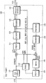
도 1은 본 발명의 일 실시예에 따른 영상 부호화 장치를 개략적으로 도시한 블록도이다. 도 1을 참조하면, 영상 부호화 장치(100)는 픽쳐 분할부(105), 예측부(110), 변환부(115), 양자화부(120), 재정렬부(125), 엔트로피 부호화부(130), 역양자화부(135), 역변환부(140), 필터부(145) 및 메모리(150)를 포함한다.1 is a block diagram schematically illustrating an image encoding apparatus according to an embodiment of the present invention. Referring to FIG. 1, the
픽쳐 분할부(105)는 입력된 픽쳐를 적어도 하나의 처리 단위로 분할할 수 있다. 이때, 처리 단위는 예측 유닛(Prediction Unit: PU)일 수도 있고, 변환 유닛(Transform Unit: TU)일 수도 있으며, 부호화 유닛(Coding Unit: CU)일 수도 있다.The picture division unit 105 may divide the input picture into at least one processing unit. In this case, the processing unit may be a prediction unit (PU), a transform unit (TU), or a coding unit (CU).
예측부(110)는 후술하는 바와 같이, 인터 예측을 수행하는 인터 예측부와 인트라 예측을 수행하는 인트라 예측부를 포함할 수 있다. 예측부(110)는, 픽쳐 분할부(105)에서의 픽쳐의 처리 단위에 대하여 예측을 수행하여 예측 블록을 생성할 수 있다. 예측부(110)에서 픽쳐의 처리 단위는 부호화 유닛일 수도 있고, 변환 유닛일 수도 있고, 예측 유닛일 수도 있다. 또한, 해당 처리 단위에 대하여 실시되는 예측이 인터 예측인지 인트라 예측인지를 결정하고, 각 예측 방법의 구체적인 내용(예컨대, 예측 모드 등)를 정할 수 있다. 이때, 예측이 수행되는 처리 단위와 예측 방법 및 구체적인 내용이 정해지는 처리 단위는 다를 수 있다. 예컨대, 예측의 방법과 예측 모드 등은 예측 유닛 단위로 결정되고, 예측의 수행은 변환 유닛 단위로 수행될 수도 있다. 생성된 예측 블록과 원본 블록 사이의 잔차값(잔차 블록: residual block)은 변환부(115)로 입력될 수 있다. 또한, 예측을 위해 사용한 예측 모드 정보, 움직임 벡터(motion vector) 정보 등은 잔차값과 함께 엔트로피 부호화부(130)에서 부호화되어 복호화기에 전달될 수 있다.As described later, the
변환부(115)는 변환 단위로 잔차 블록에 대한 변환(transform)을 수행하고 변환 계수를 생성한다. 변환부(115)에서의 변환 단위는 변환 유닛일 수 있으며, 쿼드 트리(quad tree) 구조를 가질 수 있다. 이때, 변환 단위의 크기는 소정의 최대 및 최소 크기의 범위 내에서 정해질 수 있다. 변환부(115)는 잔차 블록을 DCT(Discrete Cosine Transform) 및/또는 DST(Discrete Sine Transform)를 이용하여 변환할 수 있다.The
양자화부(120)는 변환부(115)에서 변환된 잔차값들을 양자화하여 양자화 계수를 생성할 수 있다. 양자화부(120)에서 산출된 값은 역양자화부(135)와 재정렬부(125)에 제공될 수 있다.The
재정렬부(125)는 양자화부(120)로부터 제공된 양자화 계수를 재정렬한다. 양자화 계수를 재정렬함으로써 엔트로피 부호화부(130)에서의 부호화의 효율을 높일 수 있다. 재정렬부(125)는 계수 스캐닝(Coefficient Scanning) 방법을 통해 2차원 블록 형태의 양자화 계수들을 1차원의 벡터 형태로 재정렬할 수 있다. 재정렬부(125)에서는 양자화부에서 전송된 계수들의 확률적인 통계를 기반으로 계수 스캔닝의 순서를 변경함으로써 엔트로피 부호화부(130)에서의 엔트로피 부호화 효율을 높일 수도 있다.The
엔트로피 부호화부(130)는 재정렬부(125)에 의해 재정렬된 양자화 계수들에 대한 엔트로피 부호화를 수행할 수 있다. 엔트로피 부호화부(130)는 재정렬부(125) 및 예측부(110)로부터 전달받은 부호화 유닛의 양자화 계수 정보 및 블록 타입 정보, 예측 모드 정보, 분할 단위 정보, 예측 유닛 정보 및 전송 단위 정보, 움직임 벡터 정보, 참조 픽쳐 정보, 블록의 보간 정보, 필터링 정보 등 다양한 정보를 부호화할 수 있다.The
엔트로피 부호화에는 지수 골롬(Exponential Golomb), CAVLC(Context-Adaptive Variable Length Coding), CABAC(Context-Adaptive Binary Arithmetic Coding)과 같은 부호화 방법들이 사용될 수 있다. 예를 들어, 엔트로피 부호화부(130)에는 가변길이 부호화(VLC: Variable Length Coding, 이하 'VLC'라 함.) 테이블과 같은 엔트로피 부호화를 수행하기 위한 테이블이 저장될 수 있고, 엔트로피 부호화부(130)는 저장된 VLC 테이블을 이용하여 엔트로피 부호화를 수행할 수 있다. 또한 다른 예로서 CABAC 엔트로피 부호화 방법에서, 엔트로피 부호화부(130)는 심볼을 이진화하여 빈(bin)으로 변환한 후 빈의 발생 확률에 따라 빈에 대한 산술 부호화(arithmetic encoding)를 수행하여 비트스트림을 생성할 수도 있다.For entropy encoding, encoding methods such as Exponential Golomb, CAVLC (Context-Adaptive Variable Length Coding), and CABAC (Context-Adaptive Binary Arithmetic Coding) may be used. For example, the
엔트로피 부호화가 적용되는 경우, 높은 발생 확률을 갖는 심볼(symbol)에 낮은 값의 인덱스(index) 및 이에 대응하는 짧은 코드워드(codeword)가 할당되고, 낮은 발생 확률을 갖는 심볼에 높은 값의 인덱스 및 이에 대응하는 긴 코드워드가 할당될 수 있다. 따라서 부호화 대상 심볼들에 대한 비트량이 감소될 수 있고, 엔트로피 부호화에 의해 영상 압축 성능이 향상될 수 있다.When entropy encoding is applied, a low value index and a corresponding short codeword are assigned to a symbol having a high probability of occurrence, and a high value index and a symbol having a low probability of occurrence, and Long codewords corresponding thereto may be allocated. Therefore, a bit amount for symbols to be encoded can be reduced, and image compression performance can be improved by entropy encoding.
역양자화부(135)는 양자화부(120)에서 양자화된 값들을 역양자화하고, 역변환부(140)는 역양자화부(135)에서 역양자화된 값들을 역변환할 수 있다. 역양자화부(135) 및 역변환부(140)에서 생성된 잔차값(Residual)은 예측부(110)에서 예측된 예측 블록과 합쳐져 복원 블록(Reconstructed Block)이 생성될 수 있다.The
필터부(145)는 디블록킹 필터 및/또는 ALF(Adaptive Loop Filter)를 복원된 픽쳐에 적용할 수 있다.The
디블록킹 필터는 복원된 픽쳐에서 블록 간의 경계에 생긴 블록 왜곡을 제거할 수 있다. ALF(Adaptive Loop Filter)는, 디블록킹 필터를 통해 블록이 필터링된 후 복원된 영상과 원래의 영상을 비교한 값을 기초로 필터링을 수행할 수 있다. ALF는 고효율을 적용하는 경우에만 수행될 수도 있다.The deblocking filter can remove block distortion caused by a boundary between blocks in the reconstructed picture. An adaptive loop filter (ALF) may perform filtering based on a value obtained by comparing a reconstructed image with an original image after a block is filtered through a deblocking filter. ALF may be performed only when high efficiency is applied.
한편, 인터 예측에 사용되는 복원 블록에 대해서 필터부(145)는 필터링을 적용하지 않을 수 있다.Meanwhile, the
메모리(150)는 필터부(145)를 통해 산출된 복원 블록 또는 픽쳐를 저장할 수 있다. 메모리(150)에 저장된 복원 블록 또는 픽쳐는 인터 예측을 수행하는 예측부(110)에 제공될 수 있다.The
부호화 유닛(Coding Unit: CU)은 픽쳐의 부호화/복호화가 수행되는 단위로서, 쿼드 트리 구조(Quad Tree Structure)를 기반으로 깊이(Depth)를 가지며 분할될 수 있다. 부호화 유닛은 64x64, 32x32, 16x16, 8x8 등의 여러 크기를 가질 수 있다.A coding unit (CU) is a unit for encoding / decoding a picture, and may be split with a depth based on a quad tree structure. The encoding unit may have various sizes such as 64x64, 32x32, 16x16, and 8x8.
부호화기는 최대 부호화 유닛(Largest Coding Unit: LCU)과 최소 부호화 유닛(Smallest Coding Unit: SCU)에 관한 정보를 복호화기에 전송할 수도 있다. 최대 부호화 유닛 및/또는 최소 부호화 유닛에 관한 정보와 함께 분할 가능한 회수에 관한 정보(깊이 정보)가 복호화기에 전송될 수 있다. 부호화 유닛이 쿼드 트리 구조를 기반으로 분할되는지에 관한 정보는 분할 플래그(Split Flag)와 같은 플래그 정보를 통해 부호화기로부터 복호화기로 전달될 수 있다.The encoder may transmit information about a largest coding unit (LCU) and a smallest coding unit (SCU) to the decoder. Information (depth information) on the number of splitting times may be transmitted to the decoder along with information on the largest coding unit and / or the smallest coding unit. Information regarding whether a coding unit is split based on a quad tree structure may be transmitted from an encoder to a decoder through flag information such as a split flag.
하나의 부호화 유닛은 복수 개의 예측 유닛으로 분할될 수 있다. 인트라 예측이 수행되는 경우에는 예측 유닛 단위로 예측 모드가 결정되어 예측 유닛 단위로 예측이 수행될 수 있다. 이 때, 예측 유닛 단위로 예측 모드가 정해지고 변환 유닛 단위로 인트라 예측이 수행될 수도 있다.One coding unit may be divided into a plurality of prediction units. When intra prediction is performed, a prediction mode is determined in units of prediction units, and prediction may be performed in units of prediction units. At this time, a prediction mode is determined in units of prediction units, and intra prediction may be performed in units of transformation units.
도 2는 본 발명의 일 실시예에 따른 예측부를 개략적으로 도시한 개념도이다. 도 2를 참조하면 예측부(200)는 인터 예측부(210) 및 인트라 예측부(220) 를 포함할 수 있다.2 is a conceptual diagram schematically showing a prediction unit according to an embodiment of the present invention. Referring to FIG. 2, the
인터 예측부(210)는 현재 픽쳐의 이전 픽쳐 또는 이후 픽쳐 중 적어도 하나의 픽쳐의 정보를 기초로 예측을 수행하여 예측 블록을 생성할 수 있다. 또한, 인트라 예측부(220)는 현재 픽쳐 내의 픽셀 정보를 기초로 예측을 수행하여 예측 블록을 생성할 수 있다.The
인터 예측부(210)는 예측 유닛에 대하여, 참조 픽쳐를 선택하고 예측 유닛과 동일한 크기의 참조 블록을 정수 픽셀 샘플 단위로 선택할 수 있다. 이어서, 인터 예측부(210)는 1/2 픽셀 샘플 단위와 1/4 픽셀 샘플 단위와 같이 정수 이하 샘플 단위로 현재 예측 유닛과 가장 유사하여 잔차 신호가 최소화되며 부호화되는 움직임 벡터 크기 역시 최소가 될 수 있는 예측 블록을 생성할 수 있다. 이때, 움직임 벡터는 정수 픽셀 이하의 단위로 표현될 수 있으며, 예컨대 루마 픽셀에 대해서는 1/4 픽셀 단위로, 크로마 픽셀에 대해서는 1/8 픽셀 단위로 표현될 수 있다.The
인터 예측부(210)가 선택한 참조 픽쳐의 인덱스와 움직임 벡터에 관한 정보는 부호화되어 복호화기에 전달될 수 있다.Information about the index and motion vector of the reference picture selected by the
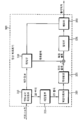
도 3은 본 발명의 일 실시예에 따른 영상 복호화 장치를 개략적으로 나타낸 블록도이다. 도 3을 참조하면, 영상 복호화기(300)는 엔트로피 복호화부(310), 재정렬부(315), 역양자화부(320), 역변환부(325), 예측부(330), 필터부(335) 및 메모리(340)를 포함할 수 있다.3 is a block diagram schematically illustrating an image decoding apparatus according to an embodiment of the present invention. Referring to FIG. 3, the
영상 부호화기에 영상 비트 스트림이 입력된 경우, 입력된 비트 스트림은 영상 부호화기에서 영상 정보가 처리된 절차에 따라서 복호화될 수 있다.When an image bit stream is input to the image encoder, the input bit stream may be decoded according to a procedure in which image information is processed in the image encoder.
엔트로피 복호화부(310)는 입력된 비트스트림에 대하여 엔트로피 복호화를 수행할 수 있으며, 엔트로피 복호화 방법은 상술한 엔트로피 부호화 방법과 유사하다. 예컨대, 영상 부호화기에서 엔트로피 부호화를 수행하기 위해 CAVLC 등의 가변 길이 부호화(VLC: Variable Length Coding, 이하 'VLC' 라 함)가 사용된 경우에는 엔트로피 복호화부(310)도 부호화기에서 사용한 VLC 테이블과 동일한 VLC 테이블을 구현하여 엔트로피 복호화를 수행할 수 있다. 영상 부호화기에서 엔트로피 부호화를 수행하기 위해, CABAC이 이용된 경우에도, 엔트로피 복호화부(310)는 이에 대응하여 CABAC을 이용한 엔트로피 복호화를 수행할 수 있다.The
엔트로피 복호화가 적용되는 경우, 높은 발생 확률을 갖는 심볼(symbol)에 낮은 값의 인덱스(index) 및 이에 대응하는 짧은 코드워드(codeword)가 할당되고, 낮은 발생 확률을 갖는 심볼에 높은 값의 인덱스 및 이에 대응하는 긴 코드워드가 할당될 수 있다. 따라서 부호화 대상 심볼들에 대한 비트량이 감소될 수 있고, 엔트로피 부호화에 의해 영상 압축 성능이 향상될 수 있다.When entropy decoding is applied, a low value index and a corresponding short codeword are assigned to a symbol having a high probability of occurrence, and a high value index and a symbol having a low probability of occurrence, and Long codewords corresponding thereto may be allocated. Therefore, a bit amount for symbols to be encoded can be reduced, and image compression performance can be improved by entropy encoding.
엔트로피 복호화부(310)에서 복호화된 정보 중 예측 블록을 생성하기 위한 정보는 예측부(330)로 제공되고 엔트로피 복호화부에서 엔트로피 복호화가 수행된 잔차값은 재정렬부(315)로 입력될 수 있다.Information for generating a prediction block among information decoded by the
재정렬부(315)는, 엔트로피 복호화부(310)에서 엔트로피 복호화된 비트 스트림을 영상 부호화기에서 재정렬한 방법을 기초로 재정렬할 수 있다. 재정렬부(315)는 1차원 벡터 형태로 표현된 계수들을 다시 2차원의 블록 형태의 계수로 복원하여 재정렬할 수 있다. 재정렬부(315)는 부호화기에서 수행된 계수 스캐닝에 관련된 정보를 제공받고 해당 부호화부에서 수행된 스캐닝 순서에 기초하여 역으로 스캐닝하는 방법을 통해 재정렬을 수행할 수 있다.The
역양자화부(320)는 부호화기에서 제공된 양자화 파라미터와 재정렬된 블록의 계수값을 기초로 역양자화를 수행할 수 있다.The
역변환부(325)는, 영상 부호화기에서 수행된 양자화 결과에 대해 부호화기의 변환부가 수행한 DCT 및 DST에 대해, 역DCT 및/또는 역DST를 수행할 수 있다. 역변환은 부호화기에서 결정된 전송 단위 또는 영상의 분할 단위를 기초로 수행될 수 있다. 부호화기의 변환부에서 DCT 및/또는 DST는 예측 방법, 현재 블록의 크기 및 예측 방향 등 복수의 정보에 따라 선택적으로 수행될 수 있고, 복호화기의 역변환부(325)는 부호화기의 변환부에서 수행된 변환 정보를 기초로 역변환을 수행할 수 있다.The
예측부(330)는 엔트로피 복호화부(310)에서 제공된 예측 블록 생성 관련 정보와 메모리(340)에서 제공된 이전에 복호화된 블록 및/또는 픽쳐 정보를 기초로 예측 블록을 생성할 수 있다. 복원 블록은 예측부(330)에서 생성된 예측 블록과 역변환부(325)에서 제공된 잔차 블록을 이용해 생성될 수 있다.The
복원된 블록 및/또는 픽쳐는 필터부(335)로 제공될 수 있다. 필터부(335)는 복원된 블록 및/또는 픽쳐에 디블록킹 필터링, SAO(Sample Adaptive Offset) 및/또는 적응적 루프 필터링(ALF) 등을 적용할 수 있다.The reconstructed block and / or picture may be provided to the
메모리(340)는 복원된 픽쳐 또는 블록을 저장하여 참조 픽쳐 또는 참조 블록으로 사용할 수 있도록 할 수 있고 또한 복원된 픽쳐를 출력부로 제공할 수 있다.The
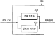
도 4는 본 발명의 일 실시예에 따른 영상 복호화 장치의 예측부를 개략적으로 나타낸 개념도이다.4 is a conceptual diagram schematically illustrating a prediction unit of an image decoding apparatus according to an embodiment of the present invention.
도 4를 참조하면, 예측부(400)는 인트라 예측부(410) 및 인터 예측부(420)를 포함할 수 있다.Referring to FIG. 4, the
인트라 예측부(410)는 해당 예측 유닛에 대한 예측 모드가 인트라 예측(intra prediction) 모드(화면 내 예측 모드)인 경우에, 현재 픽쳐 내의 픽셀 정보를 기초로 예측 블록을 생성할 수 있다.The
인터 예측부(420)는 해당 예측 유닛에 대한 예측 모드가 인터 예측(inter prediction) 모드(화면 간 예측 모드)인 경우에, 영상 부호화기에서 제공된 현재 예측 유닛의 인터 예측에 필요한 정보, 예컨대 움직임 벡터, 참조 픽쳐 인덱스 등에 관한 정보를 이용해 현재 예측 유닛이 포함된 현재 픽쳐의 이전 픽쳐 또는 이후 픽쳐 중 적어도 하나의 픽쳐에 포함된 정보를 기초로 현재 예측 유닛에 대한 인터 예측을 수행할 수 있다.When the prediction mode for the prediction unit is an inter prediction mode (inter prediction mode), the
이때, 움직임 정보는, 부호화기로부터 수신되는 부호화 유닛의 스킵 플래그, 머지 플래그 등이 확인된 경우, 이에 대응하여 유도될 수 있다.At this time, the motion information may be derived corresponding to the skip flag, merge flag, or the like of the encoding unit received from the encoder.
이하, 발명의 구성 또는 표현에 따라 "영상" 또는 "화면"이 "픽쳐"와 같은 의미를 나타낼 수 있는 경우,"픽쳐"는 "영상" 또는 "화면"으로 기술될 수 있다. 또한 인터 예측(inter prediction)과 화면 간 예측은 동일한 의미를 가지며, 인트라 예측(intra prediction)과 화면 내 예측은 동일한 의미를 가진다.Hereinafter, when "image" or "screen" may represent the same meaning as "picture" according to the configuration or expression of the invention, "picture" may be described as "image" or "screen". In addition, inter prediction and inter prediction have the same meaning, and intra prediction and intra prediction have the same meaning.
인터 예측 모드의 경우에 부호화기 및 복호화기는 현재 블록의 움직임 정보를 도출하고, 도출된 움직임 정보에 기반하여 현재 블록에 대한 인터 예측을 수행할 수 있다.In the case of the inter prediction mode, the encoder and the decoder may derive motion information of the current block and perform inter prediction on the current block based on the derived motion information.
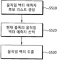
도 5는 인터 예측 모드에서 AMVP(Advanced Motion Vector Predictor)가 적용되는 경우, 움직임 벡터 도출 방법의 일 실시예를 개략적으로 나타내는 흐름도이다.5 is a flowchart schematically illustrating an embodiment of a method for deriving a motion vector when AMVP (Advanced Motion Vector Predictor) is applied in an inter prediction mode.
도 5를 참조하면, 부호화기 및 복호화기는 현재 블록에 대한 움직임 벡터 예측자 후보 리스트를 생성할 수 있다(S510). 여기서, 움직임 벡터 예측자(MVP: Motion Vector Predictor)는 현재 블록의 움직임 벡터에 대한 예측값을 나타낼 수 있다. 이하, 움직임 벡터 예측자 및 MVP는 동일한 의미를 가진다.Referring to FIG. 5, the encoder and decoder may generate a motion vector predictor candidate list for the current block (S510). Here, a motion vector predictor (MVP) may indicate a prediction value for a motion vector of a current block. Hereinafter, the motion vector predictor and MVP have the same meaning.
부호화기 및 복호화기는 현재 블록에 인접하고 이용 가능한(available) 주변 블록 및/또는 각 참조 픽쳐에 포함된 시간적(temporal) 참조 블록의 움직임 벡터를 이용하여 움직임 벡터 예측자 후보 리스트를 생성할 수 있다. 상기 시간적 참조 블록은 현재 블록과 동일 위치에 있는(co-located) 각 참조 픽쳐의 블록(이하, 설명의 편의를 위해 ‘동일 위치 블록’(co-located block)이라 함)을 기반으로 도출될 수 있다. 시간적 참조 블록을 도출하는 방법의 구체적인 실시예는 후술하기로 한다.The encoder and decoder may generate a motion vector predictor candidate list by using motion vectors of neighboring blocks available adjacent to the current block and / or temporal reference blocks included in each reference picture. The temporal reference block may be derived based on a block of each reference picture co-located with the current block (hereinafter referred to as a 'co-located block' for convenience of description). have. A specific embodiment of a method for deriving a temporal reference block will be described later.
부호화기 및 복호화기는 움직임 벡터 예측자 후보 리스트에 포함된 움직임 벡터 예측자 후보들 중 현재 블록에 대한 움직임 벡터 예측자를 선택할 수 있다(S520).The encoder and decoder may select a motion vector predictor for the current block from among motion vector predictor candidates included in the motion vector predictor candidate list (S520).
부호화기는 움직임 벡터 예측자 후보 리스트에 포함된 움직임 벡터 예측자 후보들에 대해 움직임 벡터 경쟁(Motion Vector Competition: MVC, 이하 ‘MVC’라 함)을 적용하여, 현재 블록에 대한 최적의 움직임 벡터 예측자를 선택할 수 있다. 움직임 벡터 예측자가 선택되면, 부호화기는 비트 스트림을 통해 움직임 벡터 예측자 인덱스를 복호화기로 전송할 수 있다. 여기서, 움직임 벡터 예측자 인덱스는, 움직임 벡터 예측자 후보 리스트에 포함된 움직임 벡터 예측자 후보들 중에서 선택된, 현재 블록의 움직임 벡터 예측자를 지시하는 인덱스를 의미한다.The encoder applies motion vector competition (Motion Vector Competition: MVC, hereinafter referred to as 'MVC') to motion vector predictor candidates included in the motion vector predictor candidate list, thereby selecting an optimal motion vector predictor for the current block. Can be. When the motion vector predictor is selected, the coder can transmit a motion vector predictor index to the decoder through a bit stream. Here, the motion vector predictor index means an index indicating a motion vector predictor of the current block, selected from among motion vector predictor candidates included in the motion vector predictor candidate list.
복호화기는 부호화기로부터 움직임 벡터 예측자 인덱스를 수신할 수 있다. 복호화기는, 수신된 움직임 벡터 예측자 인덱스를 이용하여, 움직임 벡터 예측자 후보 리스트에 포함된 움직임 벡터 예측자 후보들 중 현재 블록에 대한 움직임 벡터 예측자를 선택할 수 있다.The decoder can receive a motion vector predictor index from an encoder. The decoder may select a motion vector predictor for the current block from among motion vector predictor candidates included in the motion vector predictor candidate list, using the received motion vector predictor index.
복호화기는 선택된 움직임 벡터 예측자를 이용하여 현재 블록의 움직임 벡터를 도출할 수 있다(S530).The decoder can derive the motion vector of the current block using the selected motion vector predictor (S530).
현재 블록에 대한 움직임 벡터 예측자가 선택되면, 부호화기는 현재 블록의 움직임 벡터와 움직임 벡터 예측자의 차분을 구할 수 있다. 이하, 움직임 벡터와 움직임 벡터 예측자의 차분은 움직임 벡터 차분(Motion Vector Difference: MVD)이라 한다. 부호화기는 움직임 벡터 자체가 아닌, 움직임 벡터 차분에 대한 정보를 복호화기로 전송할 수 있다. 이 때, 움직임 벡터 차분이 작을수록 부호화기에서 복호화기로 전송되는 정보량이 감소될 수 있다.When the motion vector predictor for the current block is selected, the encoder can obtain a difference between the motion vector of the current block and the motion vector predictor. Hereinafter, the difference between the motion vector and the motion vector predictor is referred to as a motion vector difference (MVD). The encoder may transmit information about the motion vector difference, not the motion vector itself, to the decoder. At this time, the smaller the motion vector difference, the smaller the amount of information transmitted from the encoder to the decoder.
복호화기는 부호화기로부터 움직임 벡터 차분에 대한 정보를 수신할 수 있다. 현재 블록에 대한 움직임 벡터 예측자가 선택되면, 복호화기는 선택된 움직임 벡터 예측자와 움직임 벡터 차분을 더하여 현재 블록의 움직임 벡터를 구할 수 있다.The decoder can receive information about the motion vector difference from the encoder. When the motion vector predictor for the current block is selected, the decoder can obtain the motion vector of the current block by adding the selected motion vector predictor and the motion vector difference.
도 6은 움직임 벡터 예측자 후보 리스트 생성 방법의 일 실시예를 개략적으로 나타내는 개념도이다.6 is a conceptual diagram schematically showing an embodiment of a method of generating a motion vector predictor candidate list.
이하, 현재 블록의 좌측 하단 코너 블록(A0, 610) 및 현재 블록의 좌측에 인접한 블록들 중 최하단에 위치한 블록(A1, 620)을 포함하는 하나의 그룹을 좌측 후보 블록 그룹이라 한다. 또한 이하, 현재 블록의 우측 상단 코너 블록(B0, 630), 현재 블록의 상단에 인접한 블록들 중 최우측에 위치한 블록(B1, 640) 및 현재 블록의 좌측 상단 코너 블록(B2, 650)을 포함하는 하나의 그룹을 상단 후보 블록 그룹이라 한다.Hereinafter, one group including a lower left corner block (A 0 , 610) of the current block and a block (A 1 , 620) located at the bottom of blocks adjacent to the left side of the current block is referred to as a left candidate block group. In addition, hereinafter, the upper right corner block (B 0 , 630) of the current block, the blocks (B 1 , 640) located at the far right of the blocks adjacent to the top of the current block, and the upper left corner block (B 2 , 650) of the current block. One group including) is referred to as a top candidate block group.
부호화기 및 복호화기는 좌측 후보 블록 그룹에서 하나의 움직임 벡터 예측자 후보를 도출할 수 있다. 여기서, 좌측 후보 블록 그룹에서 도출된 움직임 벡터 예측자 후보는 MVA로 나타내어질 수 있다. 예를 들어, 부호화기 및 복호화기는 좌측 후보 블록 그룹에 포함된 블록들을 A0 -> A1 순서로 스캔하면서, 현재 블록과 참조 픽쳐 인덱스가 동일하고 이용 가능한 첫 번째 블록의 움직임 벡터를 현재 블록의 움직임 벡터 예측자 후보(MVA)로 선택할 수 있다.The encoder and decoder can derive one motion vector predictor candidate from the left candidate block group. Here, the motion vector predictor candidate derived from the left candidate block group may be represented by MV A. For example, the encoder and the decoder scan the blocks included in the left candidate block group in the order of A 0- > A 1 , and the motion vector of the first block having the same reference block index as the current block and the available motion vector is the motion of the current block. It can be selected as a vector predictor candidate (MV A ).
부호화기 및 복호화기는 상단 후보 블록 그룹에서 하나의 움직임 벡터 예측자 후보를 도출할 수 있다. 여기서, 상단 후보 블록 그룹에서 도출된 움직임 벡터 예측자 후보는 MVB로 나타내어질 수 있다. 예를 들어, 부호화기 및 복호화기는 상단 후보 블록 그룹에 포함된 블록들을 B0 -> B1 -> B2 순서로 스캔하면서, 현재 블록과 참조 픽쳐 인덱스가 동일하고 이용 가능한 첫 번째 블록의 움직임 벡터를 현재 블록의 움직임 벡터 예측자 후보(MVB)로 선택할 수 있다.The encoder and decoder can derive one motion vector predictor candidate from the top candidate block group. Here, the motion vector predictor candidate derived from the top candidate block group may be represented by MV B. For example, the encoder and the decoder scan the blocks included in the upper candidate block group in the order of B 0- > B 1- > B 2 , and the motion vector of the first block that is the same as the current block and the reference picture index is available. It can be selected as a motion vector predictor candidate (MV B ) of the current block.
또한, 부호화기 및 복호화기는 참조 픽쳐 내의 시간적 참조 블록(Col, 660)의 움직임 벡터를 현재 블록의 움직임 벡터 예측자 후보로 선택할 수 있다. 여기서, 시간적 참조 블록(660)의 움직임 벡터는 MVcol로 나타내어질 수 있다.Also, the encoder and decoder may select a motion vector of the temporal reference blocks (Col, 660) in the reference picture as a motion vector predictor candidate of the current block. Here, the motion vector of the
상술한 실시예에서, 좌측 후보 블록 그룹에서 도출된 움직임 벡터 예측자 후보 및 상단 후보 블록 그룹에서 도출된 움직임 벡터 예측자 후보는 공간적 움직임 벡터 예측자(spatial motion vector predictor)로 불릴 수 있다. 또한, 참조 픽쳐 내의 시간적 참조 블록으로부터 도출된 움직임 벡터 예측자 후보는 시간적 움직임 벡터 예측자(TMVP: Temporal Motion Vector Predictor)로 불릴 수 있다. 따라서, 움직임 벡터 예측자 후보에는 공간적 움직임 벡터 예측자 및 시간적 움직임 벡터 예측자가 있을 수 있으며, 움직임 벡터 예측자 후보 리스트는 공간적 움직임 벡터 예측자 및/또는 시간적 움직임 벡터 예측자를 포함할 수 있다.In the above-described embodiment, the motion vector predictor candidate derived from the left candidate block group and the motion vector predictor candidate derived from the top candidate block group may be referred to as a spatial motion vector predictor. Also, a motion vector predictor candidate derived from a temporal reference block in a reference picture may be called a temporal motion vector predictor (TMVP). Accordingly, the motion vector predictor candidate may include a spatial motion vector predictor and a temporal motion vector predictor, and the motion vector predictor candidate list may include a spatial motion vector predictor and / or a temporal motion vector predictor.
부호화기 및 복호화기는 상술한 방법에 의해 선택된 움직임 벡터 예측자 후보들 중 중복된 후보를 제거할 수 있다. 부호화기 및 복호화기는 남은 움직임 벡터 예측자 후보들을 이용하여 움직임 벡터 예측자 후보 리스트를 구성할 수 있다.The encoder and decoder may remove duplicate candidates among motion vector predictor candidates selected by the above-described method. The encoder and decoder may construct a motion vector predictor candidate list using the remaining motion vector predictor candidates.
움직임 벡터 예측이 수행되는 경우, 공간적 움직임 벡터 예측자뿐만 아니라 시간적 움직임 벡터 예측자(TMVP: Temporal Motion Vector Predictor)도 움직임 벡터 예측자 후보로 사용될 수 있다. 상술한 바와 같이, 시간적 움직임 벡터 예측자는 참조 픽쳐(예를 들어, 현재 픽쳐와 인접하거나 현재 픽쳐와의 시간적 거리가 가까운 픽쳐) 내의 시간적 참조 블록으로부터 도출된 움직임 벡터 예측자 후보를 의미할 수 있다. 이하, 시간적 움직임 벡터 예측자를 포함하여, 참조 픽쳐 내의 움직임 벡터는 시간적 움직임 벡터(temporal motion vector)라 한다. 또한, 참조 픽쳐 내의 움직임 정보(예를 들어, 움직임 벡터 및 참조 픽쳐 인덱스)는 시간적 움직임 정보라 한다.When motion vector prediction is performed, not only a spatial motion vector predictor but also a temporal motion vector predictor (TMVP) can be used as a candidate motion vector predictor. As described above, the temporal motion vector predictor may refer to a motion vector predictor candidate derived from a temporal reference block in a reference picture (for example, a picture adjacent to the current picture or close to a temporal distance from the current picture). Hereinafter, a motion vector in a reference picture, including a temporal motion vector predictor, is referred to as a temporal motion vector. In addition, motion information (eg, a motion vector and a reference picture index) in a reference picture is referred to as temporal motion information.
현재 블록에 대한 시간적 움직임 벡터 예측자를 도출하기 위해서는, 이전에 복호화된 픽쳐의 움직임 정보가 저장되어 있어야 한다. 따라서, 복호화된 픽쳐 및/또는 블록이 메모리(참조 픽쳐 버퍼 및/또는 복호화 픽쳐 버퍼(DPB: Decoded Picture Buffer))에 저장될 때, 복호화된 움직임 정보가 복호화된 픽쳐 및/또는 블록과 함께 저장될 수 있다. 움직임 정보가 저장되는 메모리는 움직임 벡터 메모리 및/또는 움직임 벡터 버퍼로도 불릴 수 있다.In order to derive a temporal motion vector predictor for the current block, motion information of a previously decoded picture must be stored. Therefore, when the decoded picture and / or block is stored in the memory (reference picture buffer and / or decoded picture buffer (DPB)), the decoded motion information is stored together with the decoded picture and / or block. You can. The memory in which motion information is stored may also be referred to as a motion vector memory and / or a motion vector buffer.
*일례로 움직임 정보는, 최소 단위 블록마다 각각 저장될 수 있다. 여기서, 최소 단위 블록은 움직임 정보가 저장되는 최소 저장 단위의 블록을 의미한다. 이하, 움직임 정보가 저장되는 최소 저장 단위의 블록은 최소 단위 블록이라 하며, 일례로 최소 단위 블록의 크기는 4x4일 수 있다.* For example, motion information may be stored for each minimum unit block. Here, the minimum unit block means a block of a minimum storage unit in which motion information is stored. Hereinafter, a block of a minimum storage unit in which motion information is stored is called a minimum unit block, and for example, the size of the minimum unit block may be 4x4.
그러나 픽쳐의 크기가 큰 경우, 움직임 정보를 저장하기 위해 요구되는 메모리의 크기가 커질 수 있다. 움직임 정보에 대한 그래뉼러리티(granularity) 및 B 슬라이스 내의 하나의 블록에 대해 두 개의 움직임 벡터가 사용될 수 있다는 점을 고려할 때, 움직임 정보 저장을 위한 메모리의 크기는 중요하다. 따라서, 소요되는 메모리의 크기 및 메모리 액세스 대역폭(memory access bandwidth)을 감소시키기 위해 시간적 움직임 정보 압축(compression) 기술이 사용될 수 있다.However, when the size of the picture is large, the size of the memory required to store motion information may be increased. Considering the granularity of motion information and the fact that two motion vectors can be used for one block in a B slice, the size of the memory for storing motion information is important. Therefore, a temporal motion information compression technique may be used to reduce the size of memory and memory access bandwidth.
시간적 움직임 정보 압축 기술의 일 실시예로, 복호화된 움직임 정보보다 큰 그래뉼러리티로 움직임 정보를 저장하기 위해 미디언 필터(median filter)가 사용될 수 있다. 미디언 필터가 움직임 벡터에 적용되는 경우, 움직임 벡터의 각 성분에 대해 필터링 및/또는 압축이 수행될 수 있다. 상기 미디언 필터를 이용한 움직임 정보 압축 프로세스는 적응적 루프 필터를 거친 복호화된 픽쳐가 메모리에 저장되기 전에 수행될 수 있다.As an embodiment of the temporal motion information compression technique, a median filter may be used to store motion information with granularity greater than the decoded motion information. When a median filter is applied to a motion vector, filtering and / or compression may be performed for each component of the motion vector. The motion information compression process using the median filter may be performed before the decoded picture that has undergone the adaptive loop filter is stored in the memory.
미디언 필터는 소정의 저장 단위 및/또는 소정의 방법에 의해 도출되는 저장 단위를 기반으로 적용될 수 있다. 여기서, 저장 단위는 움직임 정보가 압축되어 저장되는 단위를 의미할 수 있다. 이하, 움직임 정보가 압축되어 저장되는 단위를 나타내는 블록은 저장 단위 블록이라 한다.The median filter may be applied based on a predetermined storage unit and / or a storage unit derived by a predetermined method. Here, the storage unit may mean a unit in which motion information is compressed and stored. Hereinafter, a block representing a unit in which motion information is compressed and stored is referred to as a storage unit block.
상기 소정의 저장 단위는 최소 단위 블록의 크기(예를 들어, 4x4)보다 큰 소정의 크기의 블록일 수 있다. 또한, 상기 저장 단위는 부호화기로부터 전송된 압축 정보를 이용하여 도출될 수도 있다. 여기서, 상기 압축 정보에는 압축 플래그 및 압축 비율 정보 등이 있을 수 있다. 상기 압축 플래그는 움직임 정보 압축이 적용되는지 여부를 지시하는 플래그를 나타내고, 상기 압축 비율 정보는 움직임 정보의 압축 비율을 나타낼 수 있다. 압축 정보를 전송하는 방법 및 압축 정보를 이용하여 저장 단위를 도출하는 방법은, 후술되는 미디언 필터를 사용하지 않는 움직임 정보 압축 기술에서와 동일하므로 생략하기로 한다.The predetermined storage unit may be a block having a predetermined size larger than the size (eg, 4x4) of the minimum unit block. Further, the storage unit may be derived using compressed information transmitted from an encoder. Here, the compression information may include compression flags and compression ratio information. The compression flag indicates a flag indicating whether motion information compression is applied, and the compression rate information may indicate a compression rate of motion information. The method of transmitting the compressed information and the method of deriving the storage unit using the compressed information are the same as in the motion information compression technique that does not use a median filter, which will be described later, and thus will be omitted.
상술한 움직임 정보 압축 과정에서는 움직임 정보가 낮은 해상도(resolution)로 저장될 수 있으므로, 움직임 정보 저장을 위한 메모리의 크기가 감소될 수 있다.In the above-described motion information compression process, since motion information may be stored at a low resolution, a size of a memory for storing motion information may be reduced.
시간적 움직임 정보 압축 기술의 다른 실시예로, 미디언 필터가 사용되지 않는 움직임 정보 저장 방법이 제공될 수 있다.As another embodiment of the temporal motion information compression technique, a method for storing motion information in which a median filter is not used may be provided.
상기 방법에서는, 저장 단위 블록 내의 움직임 벡터 중에서 대표 움직임 벡터가 선택될 수 있고, 선택된 대표 움직임 벡터가 상기 저장 단위 블록 내의 모든 최소 단위 블록에 할당될 수 있다. 따라서, 움직임 정보가 낮은 해상도로 저장될 수 있고, 움직임 정보 저장을 위한 메모리의 크기가 감소될 수 있다. 미디언 필터가 아닌 대표 움직임 벡터가 사용되는 경우, 미디언 필터가 사용되는 경우에 비해 코딩 효율이 조금 더 낮을 수 있으나, 계산량 및/또는 복잡도가 감소될 수 있다. 이하, 미디언 필터가 사용되지 않는 움직임 정보 저장 방법의 실시예들이 서술된다.In the above method, a representative motion vector may be selected from among motion vectors in a storage unit block, and the selected representative motion vector may be allocated to all minimum unit blocks in the storage unit block. Therefore, motion information can be stored at a low resolution, and the size of the memory for storing motion information can be reduced. When a representative motion vector other than the median filter is used, the coding efficiency may be slightly lower than the case where the median filter is used, but computational complexity and / or complexity may be reduced. Hereinafter, embodiments of a method for storing motion information in which a median filter is not used are described.
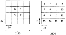
도 7은 저장 단위 블록의 일 실시예를 개략적으로 나타내는 개념도이다.7 is a conceptual diagram schematically showing an embodiment of a storage unit block.
저장 단위 블록 내의 임의의 픽셀의 좌표가 (x, y)이고, 저장 단위 블록의 너비는 W, 높이는 H라는 변수로 정의된다고 가정한다. 저장 단위 블록에 포함되는 최소 단위 블록의 개수 및 크기는 도 7의 실시예에 한정되는 것은 아니며, 예를 들어, 저장 단위 블록에 포함되는 최소 단위 블록의 개수는 16보다 크거나 작을 수 있다.It is assumed that the coordinates of an arbitrary pixel in the storage unit block are (x, y), and the width of the storage unit block is defined by the variables W and H. The number and size of the minimum unit blocks included in the storage unit block is not limited to the embodiment of FIG. 7. For example, the number of minimum unit blocks included in the storage unit block may be greater than or less than 16.
이하, 후술되는 도 8 내지 도 15의 실시예에서는, ((x>>log2W)<<log2W, (y>>log2H)<<log2H)에 존재하는 픽셀을 포함하는 최소 단위 블록은 좌측 상단 블록(710), (((x>>log2W)<<log2W)+W-1, (y>>log2H)<<log2H)에 존재하는 픽셀을 포함하는 최소 단위 블록은 우측 상단 블록(720), ((x>>log2W)<<log2W, ((y>>log2H)<<log2H)+H-1)에 존재하는 픽셀을 포함하는 최소 단위 블록은 좌측 하단 블록(730), (((x>>log2W)<<log2W)+W-1, ((y>>log2H)<<log2H)+H-1)에 존재하는 픽셀을 포함하는 최소 단위 블록은 우측 하단 블록(740)이라는 용어로 정의되어 사용된다.Hereinafter, in the embodiments of FIGS. 8 to 15 to be described later, ((x >> log 2 W) << log 2 W, (y >> log 2 H) << log 2 H) includes pixels The minimum unit block is the pixel in the upper
또한, (((x>>log2W)<<log2W)+W/2-1, ((y>>log2H)<<log2H)+H/2-1)에 존재하는 픽셀을 포함하는 최소 단위 블록은 좌측 상단 센터 블록(750), (((x>>log2W)<<log2W)+W/2, ((y>>log2H)<<log2H)+H/2-1)에 존재하는 픽셀을 포함하는 최소 단위 블록은 우측 상단 센터 블록(760), (((x>>log2W)<<log2W)+W/2-1, ((y>>log2H)<<log2H)+H/2)에 존재하는 픽셀을 포함하는 최소 단위 블록은 좌측 하단 센터 블록(770), (((x>>log2W)<<log2W)+W/2, ((y>>log2H)<<log2H)+H/2)에 존재하는 픽셀을 포함하는 최소 단위 블록은 우측 하단 센터 블록(780)이라는 용어로 정의되어 사용된다.Also, (((x >> log 2 W) << log 2 W) + W / 2-1, ((y >> log 2 H) << log 2 H) + H / 2-1) The minimum unit block including pixels is the upper
여기서, 각각의 블록들(좌측 상단 블록(710), 우측 상단 블록(720), 좌측 하단 블록(730), 우측 하단 블록(740), 좌측 상단 센터 블록(750), 우측 상단 센터 블록(760), 좌측 하단 센터 블록(770), 우측 하단 센터 블록(780))은, 상술된 바와 같이, 이에 포함된 픽셀의 좌표에 의해 특정될 수 있다. 예를 들어, 저장 단위 블록의 크기가 16x16인 경우, 좌측 상단 블록은 ((x>>4)<<4, (y>>4)<<4)에 의해 특정될 수 있다.Here, each of the blocks (upper
도 8은 저장 단위 블록의 다른 실시예를 개략적으로 나타내는 개념도이다.8 is a conceptual diagram schematically showing another embodiment of a storage unit block.
저장 단위 블록은 움직임 정보가 압축, 저장되는 단위를 나타낼 수 있다. 저장 단위 블록은 최소 단위 블록(예를 들어, 4x4 크기의 블록)보다 큰 소정의 크기의 블록일 수 있으며, 예를 들어, 16x16 크기의 블록이 저장 단위 블록으로 사용될 수 있다. 이 때, 일례로 저장 단위 블록에 포함된 16개의 최소 단위 블록은 각각 하나의 움직임 정보를 가질 수 있다.The storage unit block may indicate a unit in which motion information is compressed and stored. The storage unit block may be a block of a predetermined size larger than the minimum unit block (for example, a 4x4 sized block), for example, a 16x16 sized block may be used as a storage unit block. At this time, for example, the 16 minimum unit blocks included in the storage unit block may each have one motion information.
또한, 저장 단위는 부호화기로부터 전송된 압축 정보를 이용하여 도출될 수도 있다. 여기서, 상기 압축 정보에는 압축 플래그 및 압축 비율 정보 등이 있을 수 있다. 상기 압축 플래그는 움직임 정보 압축 과정이 적용되는지 여부를 지시할 수 있고, 상기 압축 비율 정보는 움직임 정보의 압축 비율을 나타낼 수 있다.Also, the storage unit may be derived using compressed information transmitted from an encoder. Here, the compression information may include compression flags and compression ratio information. The compression flag may indicate whether a motion information compression process is applied, and the compression rate information may indicate a compression rate of motion information.
상기 압축 정보는 SPS(Sequence Parameter Set), PPS(Picture Parameter Set) 또는 슬라이스 헤더(slice header)에 포함되어 부호화기로부터 복호화기로 전송될 수 있다. 다음 표 1은 압축 정보가 정의된 SPS의 일 실시예를 나타낸다. 표 1의 실시예에서는 상기 압축 정보가 SPS에서 정의되지만, 이는 PPS 또는 슬라이스 헤더에서 정의될 수도 있다.The compression information may be included in a Sequence Parameter Set (SPS), Picture Parameter Set (PPS) or slice header, and transmitted from the encoder to the decoder. Table 1 below shows an embodiment of SPS in which compression information is defined. In the embodiment of Table 1, the compression information is defined in the SPS, but it may also be defined in the PPS or slice header.
[표 1][Table 1]
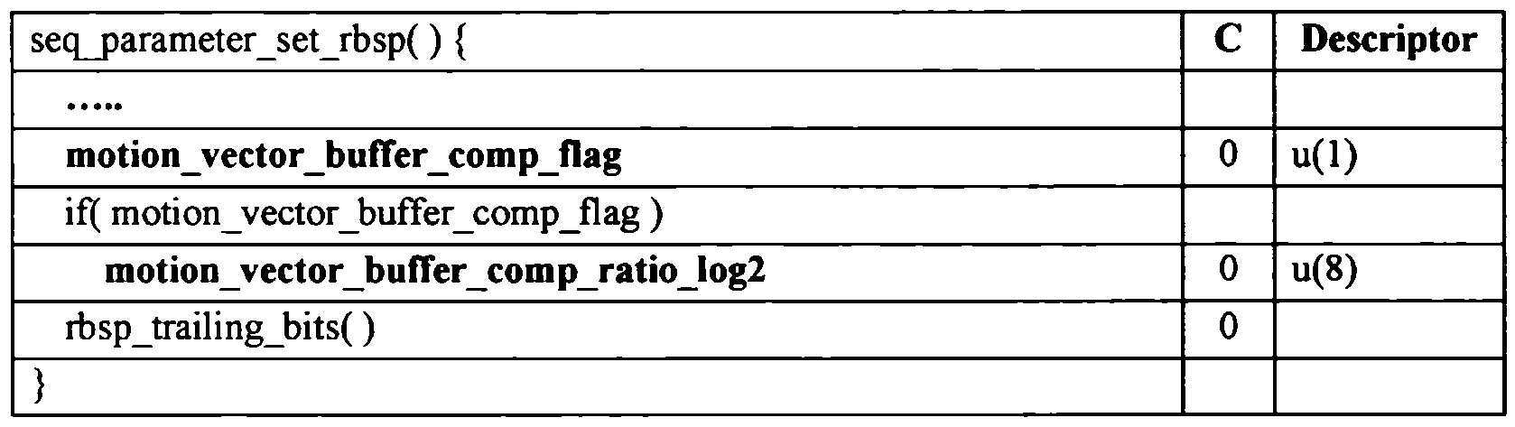
여기서, motion_vertor_buffer_comp_flag는 상기 압축 플래그에 해당될 수 있다. 예를 들어, motion_vertor_buffer_comp_flag가 1인 경우, 상기 압축 플래그는 움직임 벡터 메모리 압축 과정이 수행됨을 지시할 수 있다.Here, motion_vertor_buffer_comp_flag may correspond to the compression flag. For example, when motion_vertor_buffer_comp_flag is 1, the compression flag may indicate that a motion vector memory compression process is performed.
motion_vector_buffer_comp_ratio_log2는 상기 압축 비율 정보에 해당될 수 있으며, SPS 내에 motion_vector_buffer_comp_ratio_log2가 존재하지 않는 경우, motion_vector_buffer_comp_ratio_log2의 값이 0으로 추정(infer)될 수 있다. 이 때, 움직임 벡터 메모리 압축 비율은 일례로 다음 수학식 1에 의해 나타내어질 수 있다.motion_vector_buffer_comp_ratio_log2 may correspond to the compression ratio information, and when motion_vector_buffer_comp_ratio_log2 does not exist in SPS, the value of motion_vector_buffer_comp_ratio_log2 may be inferred to be 0. At this time, the motion vector memory compression ratio may be represented by
[수학식 1][Equation 1]
MVBufferCompRatio = 1 << motion_vector_buffer_comp_ratio_log2MVBufferCompRatio = 1 << motion_vector_buffer_comp_ratio_log2
또는or
motion_vector_buffer_comp_ratio motion_vector_buffer_comp_ratio
= 1 << motion_vector_buffer_comp_ratio_log2= 1 << motion_vector_buffer_comp_ratio_log2
여기서, MVBufferCompRatio 및 motion_vector_buffer_comp_ratio는 움직임 벡터 메모리 압축 비율을 나타낼 수 있다. 예를 들어, motion_vector_buffer_comp_ratio_log2 값이 2인 경우, MVBufferCompRatio 및 motion_vector_buffer_comp_ratio 값은 4일 수 있다.Here, MVBufferCompRatio and motion_vector_buffer_comp_ratio may indicate a motion vector memory compression ratio. For example, when the motion_vector_buffer_comp_ratio_log2 value is 2, the MVBufferCompRatio and motion_vector_buffer_comp_ratio values may be 4.
도 8을 참조하면, 일 실시예로 motion_vertor_buffer_comp_flag가 1이고 motion_vector_buffer_comp_ratio가 4인 경우, 저장 단위 블록은 가로 4줄, 세로 4줄씩 4x4 (MVBufferCompRatio-by-MVBufferCompRatio 또는 motion_vector_buffer_comp_ratio-by-motion_vector_buffer_comp_ratio) 형태로 배열된 총 16개의 최소 단위 블록으로 구성될 수 있다. 여기서, 저장 단위 블록은 항상 정방형의 모양을 가질 수 있다. 이 때, 저장 단위 블록을 구성하는 16개의 최소 단위 블록은, 각각 4x4 크기의 블록일 수 있고 각각 하나의 움직임 벡터를 가질 수 있다. 이 때 저장 단위 블록의 전체 크기는 16x16이고, 하나의 저장 단위 블록은 16개의 움직임 벡터를 가질 수 있다.Referring to FIG. 8, in one embodiment, when motion_vertor_buffer_comp_flag is 1 and motion_vector_buffer_comp_ratio is 4, the storage unit block is 4x4 by 4 rows and 4 rows vertically. It may be composed of 16 minimum unit blocks. Here, the storage unit block may always have a square shape. At this time, the 16 minimum unit blocks constituting the storage unit block may be 4x4 sized blocks, and may each have one motion vector. At this time, the total size of the storage unit block is 16x16, and one storage unit block may have 16 motion vectors.
다음 표 2는 압축 정보가 정의된 SPS(또는 PPS 또는 슬라이스 헤더)의 다른 실시예를 나타낸다.Table 2 below shows another embodiment of SPS (or PPS or slice header) in which compression information is defined.
[표 2][Table 2]
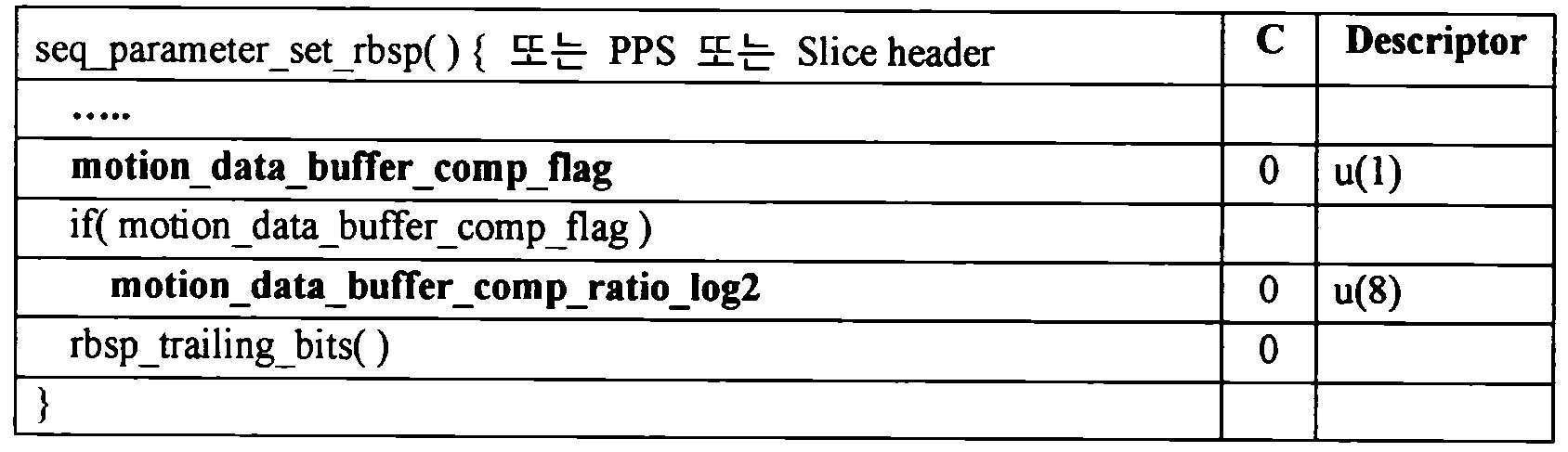
여기서, motion_data_buffer_comp_flag는 움직임 정보 메모리 압축 과정이 적용되는지 여부를 지시하는 압축 플래그에 해당될 수 있다. 예를 들어, motion_data_buffer_comp_flag가 1인 경우, 상기 압축 플래그는 움직임 정보 메모리 압축 과정이 수행됨을 지시할 수 있다.Here, motion_data_buffer_comp_flag may correspond to a compression flag indicating whether a motion information memory compression process is applied. For example, when motion_data_buffer_comp_flag is 1, the compression flag may indicate that the motion information memory compression process is performed.
motion_data_buffer_comp_ratio_log2는 움직임 정보의 압축 비율을 나타내는 압축 비율 정보에 해당될 수 있다. 이 때, 움직임 벡터 메모리 압축 비율은 수학식 1에서와 동일한 방식으로 도출될 수 있으며, 저장 단위 블록은 항상 정방형의 모양을 가질 수 있다. 예를 들어, motion_data_buffer_comp_ratio_log2가 1이면 저장 단위 블록의 크기가 8x8, motion_data_buffer_comp_ratio_log2가 2이면 저장 단위 블록의 크기가 16x16, motion_data_buffer_comp_ratio_log2가 3이면 저장 단위 블록의 크기가 32x32일 수 있다. 다른 예로, motion_data_buffer_comp_ratio_log2는 로그 스케일(log scale)이 아닌 정수(integer) 단위로 정의될 수도 있다. 예를 들어, motion_data_buffer_comp_ratio_log2가 1이면 저장 단위 블록의 크기가 8x8, motion_data_buffer_comp_ratio_log2가 2이면 저장 단위 블록의 크기가 12x12, motion_data_buffer_comp_ratio_log2가 3이면 저장 단위 블록의 크기가 16x16일 수도 있다.motion_data_buffer_comp_ratio_log2 may correspond to compression ratio information indicating a compression ratio of motion information. At this time, the motion vector memory compression ratio may be derived in the same manner as in
다음 표 3은 압축 정보가 정의된 SPS(또는 PPS 또는 슬라이스 헤더)의 또 다른 실시예를 나타낸다.Table 3 below shows another embodiment of the SPS (or PPS or slice header) in which compression information is defined.
[표 3][Table 3]
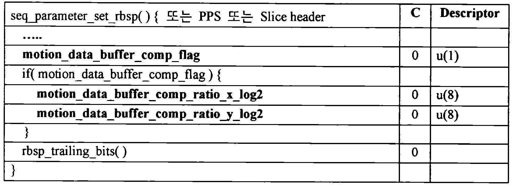
여기서, motion_data_buffer_comp_ratio_x_log2 및 motion_data_buffer_comp_ratio_y_log2는 움직임 정보의 압축 비율을 나타내는 압축 비율 정보에 해당될 수 있다. motion_data_buffer_comp_ratio_x_log2는 움직임 정보의 x축 방향(가로 방향) 압축 비율을 나타낼 수 있고, motion_data_buffer_comp_ratio_y_log2는 움직임 정보의 y축 방향(세로 방향) 압축 비율을 나타낼 수 있다. 표 3의 실시예에서는, x축 방향의 압축 비율과 y축 방향의 압축 비율이 분리되어 정의되므로, 저장 단위 블록은 정방형이 아닌 직사각형(rectangular) 모양을 가질 수 있다.Here, motion_data_buffer_comp_ratio_x_log2 and motion_data_buffer_comp_ratio_y_log2 may correspond to compression ratio information indicating a compression ratio of motion information. motion_data_buffer_comp_ratio_x_log2 may indicate the compression ratio of the x-axis direction (horizontal direction) of motion information, and motion_data_buffer_comp_ratio_y_log2 may represent the y-axis direction (vertical direction) compression ratio of motion information. In the embodiment of Table 3, since the compression ratio in the x-axis direction and the compression ratio in the y-axis direction are defined separately, the storage unit block may have a rectangular shape rather than a square.
상술한 실시예들에서 압축 정보는 SPS, PPS 또는 슬라이스 헤더 내에서 정의되나, 구현 및/또는 필요에 따라 압축 정보는 프로파일(profile) 및/또는 레벨(level)에서 정의될 수도 있다.In the above-described embodiments, compression information is defined in an SPS, PPS or slice header, but compression information may be defined in a profile and / or level according to implementation and / or needs.
저장 단위 블록 및/또는 최소 단위 블록은 상술한 바와 같이 다양한 방법으로 정해질 수 있다. 이하 후술되는 시간적 움직임 정보 압축 방법의 실시예들에서는, 설명의 편의상 저장 단위 블록의 크기는 16x16, 최소 단위 블록의 크기는 4x4라 가정한다. 또한, 하나의 저장 단위 블록은 4x4 형태로 배열된 16개의 최소 단위 블록으로 구성된다고 가정한다.The storage unit block and / or the minimum unit block can be determined in various ways as described above. In embodiments of the temporal motion information compression method described below, it is assumed that the size of the storage unit block is 16x16 and the size of the minimum unit block is 4x4 for convenience of description. In addition, it is assumed that one storage unit block is composed of 16 minimum unit blocks arranged in a 4x4 format.
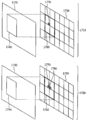
도 9는 시간적 움직임 정보 압축 방법의 일 실시예를 개략적으로 나타내는 개념도이다. 도 9에서, (X0,Y0)~(X15,Y15)는 움직임 벡터를 나타내고, ref_idx n(n은 0 이상의 정수)은 참조 픽쳐 인덱스를 나타낸다. 시간적 움직임 정보 압축 과정은, 적응적 루프 필터를 거친 복호화된 픽쳐가 메모리에 저장되기 전에 수행될 수 있다.9 is a conceptual diagram schematically showing an embodiment of a method for compressing temporal motion information. In FIG. 9, (X0, Y0) to (X15, Y15) represent motion vectors, and ref_idx n (n is an integer greater than or equal to 0) represents a reference picture index. The temporal motion information compression process may be performed before the decoded picture that has undergone the adaptive loop filter is stored in the memory.
도 9의 실시예에서, 저장 단위 블록(910, 920)은 가로 4줄, 세로 4줄씩 4x4 형태로 배열된 총 16개의 최소 단위 블록으로 구성된다고 가정한다. 여기서, 상기 16개의 최소 단위 블록 각각은 하나의 움직임 정보를 가질 수 있고, 하나의 저장 단위 블록은 16개의 움직임 정보를 가질 수 있다. 상기 저장 단위 블록은 소정의 크기를 가진 블록으로 결정될 수도 있고, 부호화기로부터 전송된 압축 비율 정보에 의해 결정될 수도 있다. 예를 들어, 도 9의 실시예는 표 1의 실시예에서 motion_vector_buffer_comp_ratio가 4인 경우에 해당될 수 있다.In the embodiment of FIG. 9, it is assumed that the storage unit blocks 910 and 920 are composed of a total of 16 minimum unit blocks arranged in 4x4 form by 4 horizontal lines and 4 vertical lines. Here, each of the 16 minimum unit blocks may have one motion information, and one storage unit block may have 16 motion information. The storage unit block may be determined as a block having a predetermined size or may be determined by compression ratio information transmitted from an encoder. For example, the embodiment of FIG. 9 may correspond to a case where motion_vector_buffer_comp_ratio is 4 in the embodiment of Table 1.
도 9의 910을 참조하면, 복호화된 최소 단위 블록 각각은 하나의 움직임 벡터 및 하나의 참조 픽쳐 인덱스를 가질 수 있다. 또한, 하나의 저장 단위 블록에 포함된 최소 단위 블록들은 서로 다른 움직임 정보를 가질 수 있다.Referring to 910 of FIG. 9, each decoded minimum unit block may have one motion vector and one reference picture index. Also, the minimum unit blocks included in one storage unit block may have different motion information.
도 9의 920을 참조하면, 부호화기 및 복호화기는 저장 단위 블록 내의 움직임 벡터 중에서, 좌측 상단(top left) 블록(TL)의 움직임 벡터(X0,Y0)를 현재 저장 단위 블록에 대한 대표 움직임 벡터로 선택할 수 있다. 이 때, 선택된 대표 움직임 벡터가 상기 저장 단위 블록 내의 모든 최소 단위 블록에 할당될 수 있다. 즉, 상기 선택된 대표 움직임 벡터가, 현재 저장 단위 블록 내의 16개의 움직임 벡터를 대표하여 메모리(움직임 벡터 버퍼)에 저장될 수 있다. 한편, 현재 픽쳐가 B 픽쳐인 경우, 참조 픽쳐 리스트0(L0)의 참조 픽쳐 및 참조 픽쳐 리스트1(L1)의 참조 픽쳐가 인터 예측에 사용될 수 있으므로, L0, L1 각각에 대한 움직임 정보가 모두 저장될 수 있다.Referring to 920 of FIG. 9, the encoder and decoder select a motion vector (X0, Y0) of a top left block (TL) from among motion vectors in a storage unit block, as a representative motion vector for the current storage unit block. You can. At this time, the selected representative motion vector may be allocated to all minimum unit blocks in the storage unit block. That is, the selected representative motion vector may be stored in a memory (motion vector buffer) representing 16 motion vectors in the current storage unit block. On the other hand, when the current picture is a B picture, since the reference picture in the reference picture list 0 (L0) and the reference picture in the reference picture list 1 (L1) can be used for inter prediction, all motion information for each of L0 and L1 is stored. Can be.
좌측 상단 블록이 인트라 모드로 부호화 및/또는 복호화된 경우, 좌측 상단 블록에 움직임 벡터가 존재하지 않을 수도 있다. 이러한 경우, (0,0)의 움직임 벡터가 상기 저장 단위 블록 내의 모든 최소 단위 블록에 할당될 수 있다. 이 때에는, (0,0)의 움직임 벡터가, 현재 저장 단위 블록 내의 16개의 움직임 벡터를 대표하여 메모리(움직임 벡터 버퍼)에 저장될 수 있다.When the upper left block is encoded and / or decoded in the intra mode, a motion vector may not exist in the upper left block. In this case, a motion vector of (0,0) can be allocated to all minimum unit blocks in the storage unit block. At this time, (0,0) motion vectors may be stored in the memory (motion vector buffer) representing 16 motion vectors in the current storage unit block.
상술한 시간적 움직임 정보 압축 방법에서는, 움직임 벡터가 낮은 해상도(resolution)로 저장될 수 있으므로, 움직임 벡터 저장을 위한 메모리 크기가 감소될 수 있다. 그러나, 좌측 상단 블록의 움직임 벡터, 즉 편향된 위치의 움직임 벡터가 일괄적으로 저장 단위 블록 내의 모든 최소 단위 블록에 할당되므로, 코딩 효율의 저하가 발생할 수 있다. 또한, 좌측 상단 블록이 인트라 모드로 코딩된 경우, 좌측 상단 블록 외의 블록들 중에 인터 모드로 코딩된 블록이 존재하는지 여부에 관계 없이 (0,0)의 움직임 벡터가 저장된다는 문제점이 있을 수 있다. 또한, 상술한 시간적 움직임 정보 압축 방법에서, 부호화기 및 복호화기는 저장 단위 블록 내의 각각의 움직임 벡터에 대응되는 참조 픽쳐 인덱스를 고려하지 않고, 동일한 움직임 벡터를 모든 최소 단위 블록에 할당하므로, 왜곡이 발생할 수 있다.In the above-described temporal motion information compression method, since the motion vector can be stored at a low resolution, the memory size for storing the motion vector can be reduced. However, since the motion vector of the upper left block, that is, the motion vector of the deflected position, is collectively allocated to all the smallest unit blocks in the storage unit block, coding efficiency may decrease. In addition, when the upper left block is coded in the intra mode, there may be a problem that a motion vector of (0,0) is stored regardless of whether there is a block coded in the inter mode among blocks other than the upper left block. In addition, in the above-mentioned temporal motion information compression method, the encoder and decoder do not consider the reference picture index corresponding to each motion vector in the storage unit block, and allocate the same motion vector to all the minimum unit blocks, so that distortion may occur. have.
도 10은 시간적 움직임 정보 압축 방법의 다른 실시예를 설명하기 위한 개념도이다.10 is a conceptual diagram illustrating another embodiment of a method for compressing temporal motion information.
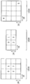
도 10은 하나의 저장 단위 블록을 나타낼 수 있다. 상기 저장 단위 블록은 복수의 최소 단위 블록으로 구성될 수 있다. 여기서, 최소 단위 블록 각각은 하나의 움직임 정보를 가질 수 있다. 일례로 상기 최소 단위 블록의 크기는 4x4이고, 상기 저장 단위 블록의 크기는 16x16일 수 있다. 이 때, 저장 단위 블록은 가로 4줄, 세로 4줄씩 4x4 형태로 배열된 총 16개의 최소 단위 블록으로 구성될 수 있다. 저장 단위 블록 및 최소 단위 블록의 크기는 상기 실시예에 한정되지 않으며, 저장 단위 블록은 NxN(N은 자연수) 형태로 배열된 최소 단위 블록으로 구성될 수 있다. 도 10에서, (X0,Y0)~(X15,Y15)는 움직임 벡터를 나타내고, ref_idx n(n은 0 이상의 정수)은 참조 픽쳐 인덱스를 나타낸다.10 may represent one storage unit block. The storage unit block may be composed of a plurality of minimum unit blocks. Here, each of the minimum unit blocks may have one motion information. For example, the size of the minimum unit block may be 4x4, and the size of the storage unit block may be 16x16. At this time, the storage unit block may be composed of a total of 16 minimum unit blocks arranged in a 4x4 form by 4 horizontal lines and 4 vertical lines. The size of the storage unit block and the minimum unit block is not limited to the above embodiment, and the storage unit block may be configured as a minimum unit block arranged in the form of NxN (N is a natural number). In FIG. 10, (X0, Y0) to (X15, Y15) represent motion vectors, and ref_idx n (n is an integer greater than or equal to 0) represents a reference picture index.
부호화기 및 복호화기는 저장 단위 블록 내의 움직임 벡터 중에서, 소정의 최소 단위 블록의 움직임 벡터를 현재 저장 단위 블록에 대한 대표 움직임 벡터로 선택할 수 있다. 이 때, 부호화기 및 복호화기는 좌측 상단 블록이 아닌 다른 특정 위치의 블록에 있는 움직임 벡터를 대표 움직임 벡터로 선택할 수 있다.The encoder and decoder may select a motion vector of a predetermined minimum unit block from among motion vectors in a storage unit block, as a representative motion vector for the current storage unit block. At this time, the encoder and decoder may select a motion vector in a block at a specific location other than the upper left block as a representative motion vector.
일 실시예로, 부호화기 및 복호화기는 우측 상단(right top) 블록(RT)의 움직임 벡터(X3,Y3), 좌측 하단(bottom left) 블록(BL)의 움직임 벡터(X12,Y12) 또는 우측 하단(bottom right) 블록(BR)의 움직임 벡터(X15,Y15)를 현재 저장 단위 블록에 대한 대표 움직임 벡터로 선택할 수 있다. 또한, 부호화기 및 복호화기는 좌측 상단 센터 블록(Center_LT 또는 C0)의 움직임 벡터, 우측 상단 센터 블록(Center_RT 또는 C1)의 움직임 벡터, 좌측 하단 센터 블록(Center_BL 또는 C2)의 움직임 벡터 또는 우측 하단 센터 블록(Center_BR 또는 C3)의 움직임 벡터를 현재 저장 단위 블록에 대한 대표 움직임 벡터로 선택할 수도 있다.In one embodiment, the encoder and decoder are motion vectors (X3, Y3) of the right top block (RT), motion vectors (X12, Y12) or bottom right of the bottom left block (BL) ( Bottom right) The motion vectors (X15, Y15) of the block BR can be selected as a representative motion vector for the current storage unit block. In addition, the encoder and decoder are motion vectors of the upper left center block (Center_LT or C0), motion vectors of the upper right center block (Center_RT or C1), motion vectors of the lower left center block (Center_BL or C2), or lower right center block ( The motion vector of Center_BR or C3) may be selected as a representative motion vector for the current storage unit block.
대표 움직임 벡터에 대응하는 최소 단위 블록의 위치는 상술한 실시예에 한하지 않으며, 저장 단위 블록 내 임의의 어떠한 최소 단위 블록의 움직임 벡터도, 상기 저장 단위 블록을 대표하는 대표 움직임 벡터로 정해질 수 있다. 예를 들어, 4x4 형태로 배열된 최소 단위 블록의 x축상의 위치를 block_x, y축상의 위치를 block_y라 하면, (block_x, block_y)(block_x = 0,1,2 또는 3, block_y = 0,1,2 또는 3)의 위치에 해당되는 어떤 블록의 움직임 벡터도 대표 움직임 벡터로 정해질 수 있다.The position of the minimum unit block corresponding to the representative motion vector is not limited to the above-described embodiment, and any motion unit of any minimum unit block in the storage unit block may be determined as a representative motion vector representing the storage unit block. have. For example, if the position on the x-axis of the smallest unit block arranged in the form of 4x4 is block_x, and the position on the y-axis is block_y, (block_x, block_y) (block_x = 0,1,2 or 3, block_y = 0,1 The motion vector of any block corresponding to the position of, 2 or 3) may be determined as a representative motion vector.
다른 실시예로, 대표 움직임 벡터에 대응하는 최소 단위 블록의 위치는, 움직임 벡터의 압축 비율에 따라 적응적으로 결정될 수도 있다. 여기서, 움직임 벡터의 압축 비율은 일례로 motion_vector_buffer_comp_ratio에 의해 나타내어질 수 있다.In another embodiment, the position of the minimum unit block corresponding to the representative motion vector may be determined adaptively according to the compression ratio of the motion vector. Here, the compression ratio of the motion vector may be represented by motion_vector_buffer_comp_ratio as an example.
예를 들어, motion_vector_buffer_comp_ratio가 4인 경우, 우측 하단 블록의 움직임 벡터를 현재 저장 단위 블록에 대한 대표 움직임 벡터로 선택할 수 있다. 또한, motion_vector_buffer_comp_ratio가 8 또는 16인 경우, 우측 하단 센터 블록의 움직임 벡터를 현재 저장 단위 블록에 대한 대표 움직임 벡터로 선택할 수 있다. 각각의 압축 비율에 따른 대표 움직임 벡터 선택 방법은 상기 예에 한정되지 않으며, 구현 및/또는 필요에 따라 달라질 수 있다.For example, when motion_vector_buffer_comp_ratio is 4, the motion vector of the lower right block may be selected as a representative motion vector for the current storage unit block. In addition, when motion_vector_buffer_comp_ratio is 8 or 16, the motion vector of the lower right center block may be selected as a representative motion vector for the current storage unit block. The representative motion vector selection method according to each compression ratio is not limited to the above example, and may be changed according to implementation and / or needs.
선택된 대표 움직임 벡터의 위치는 움직임 벡터 저장을 위한 대표 위치에 해당될 수 있으며, 대표 움직임 벡터는 저장 단위 블록 전체를 대표할 수 있다. 즉, 선택된 대표 움직임 벡터는 상기 저장 단위 블록 내의 모든 최소 단위 블록에 할당될 수 있으며, 상기 선택된 대표 움직임 벡터가, 현재 저장 단위 블록 내의 모든 움직임 벡터를 대표하여 메모리(움직임 벡터 버퍼)에 저장될 수 있다.The location of the selected representative motion vector may correspond to a representative location for storing the motion vector, and the representative motion vector may represent the entire storage unit block. That is, the selected representative motion vector may be allocated to all the minimum unit blocks in the storage unit block, and the selected representative motion vector may be stored in a memory (motion vector buffer) representing all motion vectors in the current storage unit block. have.
상술한 실시예는 움직임 벡터를 중심으로 서술되고 있으나, 이에 한정되지 않고 일반적인 움직임 정보에 적용될 수 있다. 여기서, 움직임 정보에는 움직임 벡터를 비롯하여 참조 픽쳐 인덱스, 예측 모드 정보(예를 들어, 예측 모드에는 L0 예측, L1 예측, 단예측(Uni prediction), 쌍예측(Bi prediction) 등이 있을 수 있다.) 등이 있을 수 있다.Although the above-described embodiment is mainly described with respect to a motion vector, it is not limited thereto and may be applied to general motion information. Here, the motion information includes a motion vector, a reference picture index, and prediction mode information (for example, the prediction mode may include L0 prediction, L1 prediction, Uni prediction, Bi prediction, etc.). There may be a back.
도 11은 시간적 움직임 정보 압축 방법의 또 다른 실시예를 개략적으로 나타내는 개념도이다. 도 11의 1110 및 1120은 각각 저장 단위 블록을 나타낼 수 있다. 도 11에서, mv_n (n=0...15)은 움직임 벡터를 나타내고, ref_m (m=0...15)은 참조 픽쳐 인덱스를 나타낸다. mv_n 및 ref_m은 각각 z-스캔 순서(z-scan order)로 최소 단위 블록에 할당되어 있다고 가정한다.11 is a conceptual diagram schematically showing another embodiment of a method for compressing temporal motion information. 1110 and 1120 of FIG. 11 may indicate a storage unit block, respectively. In FIG. 11, mv_n (n = 0 ... 15) represents a motion vector, and ref_m (m = 0 ... 15) represents a reference picture index. It is assumed that mv_n and ref_m are allocated to the minimum unit block in z-scan order, respectively.
도 11의 1110을 참조하면, 부호화기 및 복호화기는 저장 단위 블록 내의 움직임 벡터 중에서, 좌측 상단 블록(1113)의 움직임 벡터(mv_0)를 상기 저장 단위 블록에 대한 대표 움직임 벡터로 선택할 수 있다. 그러나, 후술되는 바와 같이, 시간적 움직임 벡터 예측자 도출시에, 동일 위치 블록 내의 우측 하단 센터에 위치한 블록이 시간적 참조 블록으로 결정될 수 있고, 상기 결정된 시간적 참조 블록의 움직임 벡터가 시간적 움직임 벡터 예측자로 결정될 수 있다. 이 때, 좌측 상단 블록(1113)의 움직임 벡터(mv_0)를 저장 단위 블록에 대한 대표 움직임 벡터로 선택하는 것은 비효율적일 수 있다. 따라서, 부호화기 및 복호화기는 좌측 상단 블록(1113)의 움직임 벡터(mv_0) 대신, 우측 하단 센터 블록(1116)의 움직임 벡터(mv_12)를 저장 단위 블록에 대한 대표 움직임 벡터로 선택할 수 있다.Referring to 1110 of FIG. 11, the encoder and decoder may select a motion vector mv_0 of the upper
도 11의 1120을 참조하면, 선택된 대표 움직임 벡터(mv_12)의 위치는 움직임 벡터 저장을 위한 대표 위치에 해당될 수 있으며, 대표 움직임 벡터는 저장 단위 블록 전체를 대표할 수 있다. 즉, 선택된 대표 움직임 벡터(mv_12)는 상기 저장 단위 블록 내의 모든 최소 단위 블록에 할당될 수 있으며, 상기 선택된 대표 움직임 벡터가, 현재 저장 단위 블록 내의 모든 움직임 벡터를 대표하여 메모리(움직임 벡터 버퍼)에 저장될 수 있다.Referring to 1120 of FIG. 11, the location of the selected representative motion vector (mv_12) may correspond to a representative location for storing a motion vector, and the representative motion vector may represent the entire storage unit block. That is, the selected representative motion vector (mv_12) may be allocated to all the minimum unit blocks in the storage unit block, and the selected representative motion vector is represented in all memory vectors in the current storage unit block in the memory (motion vector buffer). Can be saved.
도 12는 시간적 움직임 정보 압축 방법의 또 다른 실시예를 개략적으로 나타내는 개념도이다.12 is a conceptual diagram schematically showing another embodiment of a method for compressing temporal motion information.
도 12의 1210, 1220에서, mv_n (n=0...15)은 움직임 벡터를 나타내고, ref_m (m=0...15)은 참조 픽쳐 인덱스를 나타낸다. mv_n 및 ref_m은 각각 z-스캔 순서(z-scan order)로 최소 단위 블록에 할당되어 있다고 가정한다. 또한, 도 12의 1230에서, (X0,Y0)~(X15,Y15)는 움직임 벡터를 나타내고, ref_idx n(n은 0 이상의 정수)은 참조 픽쳐 인덱스를 나타낸다.In 1210 and 1220 of FIG. 12, mv_n (n = 0 ... 15) indicates a motion vector, and ref_m (m = 0 ... 15) indicates a reference picture index. It is assumed that mv_n and ref_m are allocated to the minimum unit block in z-scan order, respectively. In addition, in 1230 of FIG. 12, (X0, Y0) to (X15, Y15) represent motion vectors, and ref_idx n (n is an integer greater than or equal to 0) represents a reference picture index.
도 12의 1210을 참조하면, 부호화기 및 복호화기는 저장 단위 블록 내의 움직임 벡터 중에서, 좌측 상단 블록의 움직임 벡터(mv_0)를 상기 저장 단위 블록에 대한 대표 움직임 벡터로 선택할 수 있다. 선택된 대표 움직임 벡터(mv_0)는 상기 저장 단위 블록 내의 모든 최소 단위 블록에 할당될 수 있으며, 상기 선택된 대표 움직임 벡터가, 현재 저장 단위 블록 내의 모든 움직임 벡터를 대표하여 메모리(움직임 벡터 버퍼)에 저장될 수 있다.Referring to 1210 of FIG. 12, the encoder and the decoder may select a motion vector (mv_0) of the upper left block from among motion vectors in a storage unit block as a representative motion vector for the storage unit block. The selected representative motion vector (mv_0) may be allocated to all minimum unit blocks in the storage unit block, and the selected representative motion vector may be stored in a memory (motion vector buffer) representing all motion vectors in the current storage unit block. Can be.
도 12의 1210에서, 부호화기 및 복호화기는 저장 단위 블록 내의 각각의 움직임 벡터에 대응되는 참조 픽쳐 인덱스를 고려하지 않고, 동일한 움직임 벡터를 모든 최소 단위 블록에 할당한다. 이 때, 참조 픽쳐 인덱스 메모리의 변경 없이 움직임 벡터 메모리만이 압축될 수 있다. 따라서, 움직임 벡터와 참조 픽쳐 인덱스 간에 불일치(inconsistency)가 발생할 수 있으며, 왜곡이 발생할 수 있다. 이러한 불일치는 시간적 움직임 벡터 예측자의 정확도를 감소시키고 움직임 벡터 스케일링의 성능을 하락시킬 수 있다. 따라서, 참조 픽쳐 인덱스를 위한 메모리 크기를 감소시키고 코딩 효율을 향상시키기 위해, 참조 픽쳐 인덱스 메모리를 움직임 벡터와 함께 압축하는 시간적 움직임 정보 압축 방법이 제공될 수 있다.In 1210 of FIG. 12, the encoder and the decoder allocate the same motion vector to all minimum unit blocks without considering the reference picture index corresponding to each motion vector in the storage unit block. At this time, only the motion vector memory can be compressed without changing the reference picture index memory. Therefore, inconsistency may occur between the motion vector and the reference picture index, and distortion may occur. This discrepancy can reduce the accuracy of the temporal motion vector predictor and degrade the performance of motion vector scaling. Accordingly, a temporal motion information compression method for compressing a reference picture index memory together with a motion vector can be provided to reduce the memory size for the reference picture index and improve coding efficiency.
도 12의 1220을 참조하면, 1210에서와 동일하게 부호화기 및 복호화기는 저장 단위 블록 내의 움직임 벡터 중에서, 좌측 상단 블록의 움직임 벡터(mv_0)를 상기 저장 단위 블록에 대한 대표 움직임 벡터로 선택할 수 있다. 또한, 부호화기 및 복호화기는 저장 단위 블록 내의 참조 픽쳐 인덱스 중에서, 좌측 상단 블록의 참조 픽쳐 인덱스(ref_0)를 상기 저장 단위 블록에 대한 대표 참조 픽쳐 인덱스로 선택할 수 있다. 즉, 부호화기 및 복호화기는 대표 움직임 벡터에 대응하는 최소 단위 블록이 가진 참조 픽쳐 인덱스를 대표 참조 픽쳐 인덱스로 선택할 수 있고, 참조 픽쳐 인덱스는 움직임 벡터와 동일한 방법으로 압축될 수 있다.Referring to 1220 of FIG. 12, as in 1210, the encoder and the decoder may select a motion vector (mv_0) of the upper left block from among motion vectors in a storage unit block as a representative motion vector for the storage unit block. Also, the encoder and the decoder may select a reference picture index (ref_0) of the upper left block from among reference picture indexes in the storage unit block as a representative reference picture index for the storage unit block. That is, the encoder and the decoder can select the reference picture index of the minimum unit block corresponding to the representative motion vector as the representative reference picture index, and the reference picture index can be compressed in the same way as the motion vector.
선택된 대표 움직임 벡터(mv_0) 및 대표 참조 픽쳐 인덱스(ref_0)는 상기 저장 단위 블록 내의 모든 최소 단위 블록에 할당될 수 있으며, 상기 선택된 대표 움직임 벡터 및 대표 참조 픽쳐 인덱스가, 현재 저장 단위 블록 내의 모든 움직임 벡터 및 모든 대표 참조 픽쳐 인덱스를 대표하여 메모리에 저장될 수 있다.The selected representative motion vector (mv_0) and the representative reference picture index (ref_0) may be allocated to all the minimum unit blocks in the storage unit block, and the selected representative motion vector and the representative reference picture index are all motions in the current storage unit block. The vector and all representative reference picture indices may be stored in the memory.
도 12의 1230을 참조하면, 부호화기 및 복호화기는 좌측 상단 블록 내의 움직임 벡터(X0,Y0) 및 참조 픽쳐 인덱스(ref_idx 2)를 각각 저장 단위 블록에 대한 대표 움직임 벡터 및 대표 참조 픽쳐 인덱스로 선택할 수 있다. 선택된 대표 움직임 벡터 및 대표 참조 픽쳐 인덱스는 상기 저장 단위 블록 내의 모든 최소 단위 블록에 할당될 수 있으며, 상기 선택된 대표 움직임 벡터 및 대표 참조 픽쳐 인덱스가, 상기 저장 단위 블록 내의 모든 움직임 벡터 및 모든 대표 참조 픽쳐 인덱스를 대표하여 메모리에 저장될 수 있다.Referring to 1230 of FIG. 12, the encoder and decoder may select a motion vector (X0, Y0) and a reference picture index (ref_idx 2) in the upper left block as a representative motion vector and a representative reference picture index for a storage unit block, respectively. . The selected representative motion vector and the representative reference picture index can be allocated to all the minimum unit blocks in the storage unit block, and the selected representative motion vector and the representative reference picture index are all motion vectors and all representative reference pictures in the storage unit block. It can be stored in memory on behalf of the index.
상술한 1220, 1230에서는 움직임 벡터뿐만 아니라 참조 픽쳐 인덱스가 함께 압축되어 저장되므로, 왜곡이 감소될 수 있다. 또한, 1220, 1230의 실시예는 상술한 도 9 내지 도 11의 실시예와 결합하여 적용될 수도 있다. 즉, 도 9 내지 도 11의 실시예에서도, 대표 움직임 벡터에 대응하는 최소 단위 블록이 가진 참조 픽쳐 인덱스가 대표 참조 픽쳐 인덱스로 선택될 수 있고, 참조 픽쳐 인덱스는 움직임 벡터와 동일한 방법으로 압축될 수 있다.In the above-described 1220 and 1230, since the motion picture as well as the reference picture index are compressed and stored together, distortion may be reduced. Further, the embodiments of 1220 and 1230 may be applied in combination with the above-described embodiments of FIGS. 9 to 11. That is, in the embodiments of FIGS. 9 to 11, the reference picture index of the smallest unit block corresponding to the representative motion vector may be selected as the representative reference picture index, and the reference picture index may be compressed in the same way as the motion vector. have.
도 13은 시간적 움직임 정보 압축 방법의 또 다른 실시예를 개략적으로 나타내는 개념도이다.13 is a conceptual diagram schematically showing another embodiment of a method for compressing temporal motion information.
상술한 도 9 내지 도 12의 실시예에서, 저장 단위 블록을 대표하는 대표 움직임 정보를 도출하기 위해 선택되는 최소 단위 블록은, 가용한(available) 움직임 정보를 포함하지 않을 수 있다. 최소 단위 블록이 가용한 움직임 정보를 포함하지 않는 경우로는, 최소 단위 블록이 가용하지 않은 경우, 최소 단위 블록이 인트라 모드로 코딩된 경우 및 최소 단위 블록에 대응하는 참조 픽쳐 리스트(예를 들어, 참조 픽쳐 리스트0, 참조 픽쳐 리스트1)에 유효한 움직임 벡터가 존재하지 않는 경우 등이 있을 수 있다.In the above-described embodiments of FIGS. 9 to 12, the minimum unit block selected to derive representative motion information representative of the storage unit block may not include available motion information. When the minimum unit block does not include available motion information, if the minimum unit block is not available, the minimum unit block is coded in the intra mode, and a reference picture list corresponding to the minimum unit block (for example, There may be a case where a valid motion vector does not exist in the
대표 움직임 정보를 도출하기 위해 선택된 최소 단위 블록이 가용한 움직임 정보를 포함하지 않는 경우, 도 9에서 상술된 바와 같이 부호화기 및 복호화기는 (0,0)의 움직임 벡터를, 상기 저장 단위 블록 내의 모든 움직임 벡터를 대표하여 메모리에 저장할 수 있다. 그러나, 이 경우에는 선택된 최소 단위 블록이 가용한 움직임 정보를 포함하지 않으면, 저장 단위 블록 내에 가용하거나 인터 모드로 코딩된 블록이 존재하는 경우에도, (0,0)의 움직임 벡터가 모든 최소 단위 블록에 할당된다는 문제점이 발생할 수 있다. 따라서, 가용한 움직임 정보를 갖는 최소 단위 블록을 선택하여 대표 움직임 정보를 결정하는, 시간적 움직임 정보 압축 방법이 제공될 수 있다.When the minimum unit block selected to derive the representative motion information does not include available motion information, as described in FIG. 9, the encoder and decoder set a motion vector of (0,0), and all motions in the storage unit block. A vector can be represented and stored in memory. However, in this case, if the selected minimum unit block does not include the available motion information, even if there are blocks available in the storage unit block or inter-mode coded, the motion vector of (0,0) is all the minimum unit blocks. May be assigned to the problem. Accordingly, a method for compressing temporal motion information, which determines representative motion information by selecting a minimum unit block having available motion information, can be provided.
일 실시예로 부호화기 및 복호화기는 소정의 순서로 저장 단위 블록 내의 최소 단위 블록을 스캔하면서, 스캔되는 최소 단위 블록이 가용한 움직임 정보를 갖는지 여부를 체크할 수 있다. 이 때, 부호화기 및 복호화기는 가용한 움직임 정보를 갖는 최소 단위 블록 중에서, 스캔 순서가 가장 빠른 블록의 움직임 정보를 상기 저장 단위 블록의 대표 움직임 정보로 선택할 수 있다. 즉, 부호화기 및 복호화기는 가용한 움직임 정보를 갖는 최소 단위 블록을 찾을 때까지 상기 스캔을 수행할 수 있다.In an embodiment, the encoder and the decoder may check whether the minimum unit block to be scanned has available motion information while scanning the minimum unit block in the storage unit block in a predetermined order. At this time, the encoder and the decoder may select, from among the smallest unit blocks having available motion information, motion information of a block having the fastest scan order as representative motion information of the storage unit block. That is, the encoder and decoder can perform the scan until it finds the smallest unit block with available motion information.
또한, 부호화기 및 복호화기는 상기 스캔 과정에서, 최소 단위 블록이 가용한 움직임 정보를 갖는지 여부(예를 들어, 상기 최소 단위 블록이 인터 모드에서 코딩되었는지 여부 등)뿐만 아니라, 최소 단위 블록이 가진 참조 픽쳐 인덱스 값이 0인지 여부를 함께 체크할 수도 있다. 이 때, 부호화기 및 복호화기는 상기 조건을 충족시키는 최소 단위 블록을 찾을 때까지 스캔을 수행하여, 상기 조건을 충족시키는 첫 번째 최소 단위 블록(스캔의 우선 순위가 가장 높은 최소 단위 블록)의 움직임 정보를 저장 단위 블록의 대표 움직임 정보로 선택할 수 있다.Also, in the scan process, the encoder and the decoder not only determine whether a minimum unit block has available motion information (eg, whether the minimum unit block is coded in inter mode, etc.), but also a reference picture of the minimum unit block. It is also possible to check whether the index value is 0. At this time, the encoder and the decoder perform a scan until a minimum unit block that satisfies the above condition is found, so that motion information of the first minimum unit block that satisfies the above condition (the smallest unit block having the highest priority of scan) It can be selected as representative motion information of the storage unit block.
*상술한 방법에 의해 선택된 대표 움직임 정보의 위치는 움직임 정보 저장을 위한 대표 위치에 해당될 수 있으며, 대표 움직임 정보는 저장 단위 블록 전체를 대표할 수 있다. 즉, 선택된 대표 움직임 정보는 상기 저장 단위 블록 내의 모든 최소 단위 블록에 할당될 수 있으며, 상기 선택된 대표 움직임 정보가, 현재 저장 단위 블록 내의 모든 움직임 정보를 대표하여 메모리에 저장될 수 있다. 예를 들어, 스캔 과정에서 최소 단위 블록이 가진 참조 픽쳐 인덱스 값이 0인지 여부가 함께 체크된 경우, 현재 저장 단위 블록 내의 모든 참조 픽쳐 인덱스를 대표하여, 0의 참조 픽쳐 인덱스 값이 메모리에 저장될 수 있다.* The location of the representative motion information selected by the above-described method may correspond to the representative location for storing the motion information, and the representative motion information may represent the entire storage unit block. That is, the selected representative motion information may be allocated to all the minimum unit blocks in the storage unit block, and the selected representative motion information may be stored in a memory representing all motion information in the current storage unit block. For example, when a reference picture index value of a minimum unit block is 0 is checked in the scan process, a reference picture index value of 0 is stored in memory, representing all reference picture indexes in the current storage unit block. Can be.
스캔 대상 최소 단위 블록 및 스캔 순서는 다양하게 정해질 수 있다. 도 13의 각 저장 단위 블록 내의 최소 단위 블록에 표시된 번호는 상기 스캔 순서를 나타낸다.The minimum unit block to be scanned and the scan order may be variously determined. The number indicated in the minimum unit block in each storage unit block in FIG. 13 indicates the scan order.
도 13의 1310을 참조하면, 부호화기 및 복호화기는 저장 단위 블록 내의 최소 단위 블록 모두를 스캔할 수 있다. 일례로, 도 13의 1313에 도시된 바와 같이, 상기 스캔 순서는 래스터 스캔 순서(raster scan order)일 수 있다. 또한 도 13의 1316, 1319에 도시된 바와 같이, 부호화기 및 복호화기는 저장 단위 블록의 센터 주변 블록부터 시작하여 점차 저장 단위 블록의 경계 쪽으로 스캔을 수행할 수도 있다.Referring to 1310 of FIG. 13, the encoder and decoder may scan all of the minimum unit blocks in the storage unit block. As an example, as illustrated in 1313 of FIG. 13, the scan order may be a raster scan order. Also, as illustrated in 1316 and 1319 of FIG. 13, the encoder and the decoder may gradually scan from the block around the center of the storage unit block toward the boundary of the storage unit block.
계산량 및 복잡도를 감소시키기 위해, 부호화기 및 복호화기는 저장 단위 블록 내의 최소 단위 블록 중에서 제한된 개수의 블록만을 스캔할 수도 있다. 일례로, 도 13의 1320에 도시된 바와 같이, 부호화기 및 복호화기는 좌측 상단 센터 블록, 우측 상단 센터 블록, 좌측 하단 센터 블록 및 우측 하단 센터 블록만을 소정의 순서로 스캔할 수 있다. 또한, 도 13의 1330에 도시된 바와 같이, 부호화기 및 복호화기는 좌측 상단 블록, 우측 상단 블록, 좌측 하단 블록 및 우측 하단 블록만을 소정의 순서로 스캔할 수도 있다.To reduce computational complexity and complexity, the encoder and decoder may scan only a limited number of blocks among the smallest unit blocks in the storage unit block. As an example, as illustrated in 1320 of FIG. 13, the encoder and the decoder may scan only the upper left center block, upper right center block, lower left center block, and lower right center block in a predetermined order. Also, as illustrated in 1330 of FIG. 13, the encoder and the decoder may scan only the upper left block, upper right block, lower left block, and lower right block in a predetermined order.
상술한 실시예는 움직임 벡터에 적용될 수 있으며, 이에 한정되지 않고 움직임 정보 모두에 적용될 수도 있다. 여기서, 움직임 정보에는 움직임 벡터, 참조 픽쳐 인덱스 등이 있을 수 있다. 예를 들어, 대표 움직임 벡터에 대응하는 최소 단위 블록이 가진 참조 픽쳐 인덱스가 대표 참조 픽쳐 인덱스로 선택될 수 있고, 참조 픽쳐 인덱스는 움직임 벡터와 동일한 방법으로 압축될 수 있다.The above-described embodiment may be applied to motion vectors, but is not limited thereto, and may be applied to all motion information. Here, the motion information may include a motion vector, a reference picture index, and the like. For example, the reference picture index of the minimum unit block corresponding to the representative motion vector may be selected as the representative reference picture index, and the reference picture index may be compressed in the same way as the motion vector.
도 14는 시간적 움직임 정보 압축 방법의 또 다른 실시예를 개략적으로 나타내는 개념도이다. 도 14의 실시예에서는, 저장 단위 블록 내의 우측 하단 센터 블록의 움직임 벡터가 대표 움직임 벡터로 선택된다고 가정한다.14 is a conceptual diagram schematically showing another embodiment of a method for compressing temporal motion information. In the embodiment of FIG. 14, it is assumed that the motion vector of the lower right center block in the storage unit block is selected as the representative motion vector.
대표 움직임 정보를 도출하기 위해 선택된 최소 단위 블록이 가용한 움직임 정보를 포함하지 않는 경우, 부호화기 및 복호화기는 (0,0)의 움직임 벡터를 상기 저장 단위 블록 내의 모든 움직임 벡터를 대표하여 메모리에 저장할 수 있으나, 도 13에서 상술한 바와 같은 문제점이 발생할 수 있다.If the minimum unit block selected to derive representative motion information does not include available motion information, the encoder and decoder can store a motion vector of (0,0) in memory representing all motion vectors in the storage unit block. However, the problem as described above in FIG. 13 may occur.
도 14의 1410을 참조하면, 우측 하단 센터 블록(1415)은 인트라 모드로 코딩된 블록이다. 따라서, 우측 하단 센터 블록(1415)은 가용한 움직임 정보를 포함하지 않을 수 있다. 이 때, (0,0)의 움직임 벡터가 모든 움직임 벡터를 대표하여 메모리에 저장될 수도 있다. 그러나, 저장 단위 블록 내에 가용한 움직임 정보를 갖는 최소 단위 블록이 존재함에도 불구하고 (0,0)의 움직임 벡터가 모든 최소 단위 블록에 할당되어, 코딩 효율이 저하되는 문제점이 발생할 수 있다. 따라서, (0,0)의 움직임 벡터 대신 가용한 움직임 정보를 갖는 최소 단위 블록이 움직임 정보 압축에 사용될 수 있다.Referring to 1410 of FIG. 14, the lower
상술한 문제점을 해결하기 위해, 부호화기 및 복호화기는 소정의 순서로 저장 단위 블록 내의 최소 단위 블록을 스캔하면서, 스캔되는 최소 단위 블록이 가용한 움직임 정보를 갖는지 여부를 체크할 수 있다. 예를 들어, 부호화기 및 복호화기는 우측 하단 센터 블록, 좌측 상단 센터 블록, 우측 상단 센터 블록 및 좌측 하단 센터 블록의 순서로 4개의 최소 단위 블록을 스캔할 수 있다. 이 때, 부호화기 및 복호화기는 가용한 움직임 정보를 갖는 갖는 최소 단위 블록 중에서, 가장 스캔 순서가 빠른 블록의 움직임 정보를 상기 저장 단위 블록의 대표 움직임 정보로 선택할 수 있다. 즉, 부호화기 및 복호화기는 가용한 움직임 정보를 갖는 최소 단위 블록을 찾을 때까지 상기 스캔을 수행할 수 있다.In order to solve the above-described problem, the encoder and decoder may scan the minimum unit block in the storage unit block in a predetermined order, and check whether the minimum unit block to be scanned has available motion information. For example, the encoder and decoder may scan four minimum unit blocks in the order of the lower right center block, upper left center block, upper right center block and lower left center block. At this time, the encoder and decoder may select motion information of a block having the fastest scan order, from among the smallest unit blocks having available motion information, as representative motion information of the storage unit block. That is, the encoder and decoder can perform the scan until it finds the smallest unit block with available motion information.
*도 14의 1420을 참조하면, 우측 하단 센터 블록은 인트라 모드로 코딩된 블록이므로, 가용한 움직임 정보를 포함하지 않을 수 있다. 따라서, 부호화기 및 복호화기는 스캔 순서상 우측 하단 센터 블록 다음에 위치하는 좌측 상단 센터 블록(1425)의 움직임 벡터(mv_3)를 현재 저장 단위 블록의 대표 움직임 벡터로 선택할 수 있다.* Referring to 1420 of FIG. 14, since the lower right center block is a block coded in intra mode, it may not include available motion information. Accordingly, the encoder and the decoder may select the motion vector mv_3 of the upper
도 14의 1430을 참조하면, 선택된 대표 움직임 벡터(mv_3)의 위치는 움직임 벡터 저장을 위한 대표 위치에 해당될 수 있으며, 대표 움직임 벡터는 저장 단위 블록 전체를 대표할 수 있다. 즉, 선택된 대표 움직임 벡터(mv_3)는 상기 저장 단위 블록 내의 모든 최소 단위 블록에 할당될 수 있으며, 상기 선택된 대표 움직임 벡터가, 현재 저장 단위 블록 내의 모든 움직임 벡터를 대표하여 메모리(움직임 벡터 버퍼)에 저장될 수 있다.Referring to 1430 of FIG. 14, the location of the selected representative motion vector (mv_3) may correspond to a representative location for storing a motion vector, and the representative motion vector may represent the entire storage unit block. That is, the selected representative motion vector (mv_3) may be allocated to all the smallest unit blocks in the storage unit block, and the selected representative motion vector is represented in the memory (motion vector buffer) representing all motion vectors in the current storage unit block. Can be saved.
도 15는 시간적 움직임 정보 압축 방법의 또 다른 실시예를 개략적으로 나타내는 개념도이다. 도 15는 저장 단위 블록(1510) 및 상기 저장 단위 블록(1510)의 주변 블록을 도시한다. 상기 주변 블록은 상기 저장 단위 블록(1510)에 인접한 블록(1,2,3,4,6,7,8,9,11,12,13,14,16,17,18,19) 및 상기 저장 단위 블록(1510)의 외부 코너에 위치한 블록(0,5,10,15)을 포함할 수 있다. 이하, 도 15의 실시예에서, 주변 블록은 저장 단위 블록(1510)의 주변 블록을 의미할 수 있다.15 is a conceptual diagram schematically showing another embodiment of a method for compressing temporal motion information. 15 shows a
상술한 도 9 내지 도 14의 실시예에 따라, 저장 단위 블록(1510)을 대표하는 대표 움직임 정보를 도출하기 위해, 부호화기 및 복호화기에 의해 선택되는 최소 단위 블록은, 가용한(available) 움직임 정보를 포함하지 않을 수 있다. 이러한 경우, 결과적으로 (0,0)의 움직임 벡터가 모든 움직임 벡터를 대표하여 메모리에 저장되는 경우가 발생할 수 있다. 최소 단위 블록이 가용한 움직임 정보를 포함하지 않는 경우로는, 최소 단위 블록이 가용하지 않은 경우, 최소 단위 블록이 인트라 모드로 코딩된 경우 및 최소 단위 블록에 대응하는 참조 픽쳐 리스트(예를 들어, 참조 픽쳐 리스트0, 참조 픽쳐 리스트1)에 유효한 움직임 벡터가 존재하지 않거나 참조 픽쳐 리스트의 움직임 벡터가 유효하지 않은 경우 등이 있을 수 있다.According to the embodiments of FIGS. 9 to 14 described above, in order to derive representative motion information representative of the
예를 들어, 도 9의 실시예에서 저장 단위 블록 내의 좌측 상단 블록이 인트라 모드로 코딩된 경우, 상기 좌측 상단 블록은 가용한 움직임 정보를 포함하지 않을 수 있다. 또한, 도 10 내지 도 12의 실시예에서, 부호화기 및 복호화기에 의해 선택되는 최소 단위 블록이 가용한 움직임 정보를 포함하지 않을 수 있다. 또한, 도 13 및 도 14의 실시예에서, 부호화기 및 복호화기에 의해 스캔되는 최소 단위 블록들이 모두 가용한 움직임 정보를 포함하지 않을 수 있다.For example, in the embodiment of FIG. 9, when the upper left block in the storage unit block is coded in the intra mode, the upper left block may not include available motion information. In addition, in the embodiments of FIGS. 10 to 12, the minimum unit block selected by the encoder and decoder may not include available motion information. In addition, in the embodiments of FIGS. 13 and 14, the minimum unit blocks scanned by the encoder and the decoder may not include available motion information.
상술한 경우에, 부호화기 및 복호화기는 (0,0)의 움직임 벡터를 대표 움직임 벡터로 선택하는 대신, 주변 블록의 움직임 정보를 이용하여 현재 저장 단위 블록에 대한 대표 움직임 벡터를 결정할 수 있다.In the above-described case, instead of selecting a motion vector of (0,0) as a representative motion vector, the encoder and decoder may determine a representative motion vector for the current storage unit block using motion information of neighboring blocks.
일 실시예로, 저장 단위 블록(1510)의 주변 블록 중에서 하나의 블록만이 가용한 움직임 정보를 갖는다고 가정한다. 이 때, 부호화기 및 복호화기는 상기 가용한 움직임 정보를 갖는 주변 블록의 움직임 정보를, 현재 저장 단위 블록(1510)의 대표 움직임 정보로 사용할 수 있다.In one embodiment, it is assumed that only one block among the neighboring blocks of the
다른 실시예로, 상기 저장 단위 블록(1510)의 주변 블록 중에서 두 개 이상의 블록이 가용한 움직임 정보를 갖는다고 가정한다.In another embodiment, it is assumed that two or more blocks among neighboring blocks of the
이 때, 일례로 부호화기 및 복호화기는 도 15의 주변 블록에 할당된 번호 순서대로 주변 블록을 스캔하면서, 참조 픽쳐 인덱스가 0인 첫 번째 주변 블록을 현재 저장 단위 블록(1510)의 대표 움직임 정보로 사용할 수 있다. 여기서, 스캔 순서는 도 15에 도시된 순서에 한정되지 않으며, 구현 및/또는 필요에 따라 달라질 수 있다.At this time, as an example, the encoder and the decoder scan the neighboring blocks in the order of numbers assigned to the neighboring blocks in FIG. 15, and use the first neighboring block having a reference picture index of 0 as representative motion information of the current
다른 예로, 부호화기 및 복호화기는 주변 블록의 움직임 정보(예를 들어, 움직임 벡터) 값의 미디언(median) 값을 구한 후, 상기 미디언 값을 현재 저장 단위 블록(1510)의 대표 움직임 정보로 사용할 수 있다. 이 때, 가용한 움직임 정보를 포함하지 않는 주변 블록은 미디언 값 도출시에 사용되지 않고 제외될 수 있다. 또한 부호화기 및 복호화기는 가용한 움직임 정보를 포함하지 않는 주변 블록에 소정의 움직임 정보 값을 할당할 수 있으며, 상기 소정의 움직임 정보 값이 할당된 주변 블록 및 가용한 움직임 정보를 포함하는 주변 블록을 함께 이용하여 미디언 값을 도출할 수도 있다. 일례로, 가용한 움직임 정보를 포함하지 않는 주변 블록에는 (0,0)의 움직임 벡터가 할당될 수 있고, 상기 (0,0)의 움직임 벡터가 미디언 값 도출에 사용될 수 있다.As another example, the encoder and decoder obtain a median value of a motion information (eg, motion vector) value of a neighboring block, and then use the median value as representative motion information of the current
또 다른 예로, 부호화기 및 복호화기는 저장 단위 블록(1510) 픽셀과 주변 블록 픽셀의 픽셀 차이값에 기반하여 상기 저장 단위 블록(1510)의 대표 움직임 정보를 결정할 수 있다.As another example, the encoder and the decoder may determine representative motion information of the
예를 들어, 0번 블록의 경우, 0번 블록의 가장 우측 하단 픽셀 및 저장 단위 블록(1510)의 가장 좌측 상단 픽셀의 픽셀값 차분에 의해, 5번 블록의 경우, 5번 블록의 가장 좌측 하단 픽셀 및 저장 단위 블록(1510)의 가장 우측 상단 픽셀의 픽셀값 차분에 의해 도출된 최종 픽셀 차이값이 대표 움직임 정보 결정에 사용될 수 있다. 또한 10번 블록의 경우, 10번 블록의 가장 좌측 상단 픽셀 및 저장 단위 블록(1510)의 가장 우측 하단 픽셀의 픽셀값 차분에 의해, 15번 블록의 경우, 15번 블록의 가장 우측 상단 픽셀 및 저장 단위 블록(1510)의 가장 좌측 하단 픽셀의 픽셀값 차분에 의해 도출된 최종 픽셀 차이값이 대표 움직임 정보 결정에 사용될 수 있다.For example, in the case of
또한, 1,2,3,4,6,7,8,9,11,12,13,14,16,17,18,19번 블록의 경우에도 각각 대표 움직임 정보 결정에 사용되는 최종 픽셀 차이값이 도출될 수 있다. 여기서, N(N은 1,2,3,4,6,7,8,9,11,12,13,14,16,17,18 또는 19)번 블록과 저장 단위 블록(1510)이 접하는 경계는 N번 경계라 한다. 이 때, 상기 N번 블록 내의 픽셀 중 N번 경계에 가장 가까이 위치한 M(M은 양의 정수, 예를 들어, M은 4, 8, 16, 32 등일 수 있다.)개의 픽셀의 픽셀값을 합한 값 및 상기 저장 단위 블록(1510) 내의 픽셀 중 N번 경계에 가장 가까이 위치한 M개의 픽셀의 픽셀값을 합한 값 사이의 차이값이 구해질 수 있다. 부호화기 및 복호화기는 상기 구해진 차이값을 M으로 나누어 평균 차이값(everage difference)을 도출할 수 있고, 상기 도출된 평균 차이값을 N번 블록의 최종 픽셀 차이값으로 사용할 수 있다.In addition, in the case of
상술한 방법에 의해 각 주변 블록에 대해 저장 단위 블록(1510)과의 최종 픽셀 차이값이 구해지면, 부호화기 및 복호화기는 주변 블록 중에서 최종 픽셀 차이값이 가장 작은 블록의 움직임 정보를 현재 저장 단위 블록(1510)의 대표 움직임 정보로 결정할 수 있다. 최종 픽셀 차이값이 가장 작은 블록이 복수 개인 경우 및/또는 주변 블록들의 최종 픽셀 차이값이 동일한 경우, 부호화기 및 복호화기는 도 15에서 할당된 번호가 가장 작은 주변 블록의 움직임 정보를 현재 저장 단위 블록(1510)의 대표 움직임 정보로 결정할 수 있다.When the final pixel difference value with the
또 다른 실시예로, 저장 단위 블록(1510)의 주변 블록이 모두 가용한 움직임 정보를 갖지 않는 경우가 있을 수 있다. 이 때, 부호화기 및 복호화기는 (0,0)의 움직임 벡터를 대표 움직임 벡터로 선택할 수 있다.As another embodiment, there may be a case where all the neighboring blocks of the
대표 움직임 정보가 결정되면, 선택된 대표 움직임 정보는 저장 단위 블록(1510) 내의 모든 최소 단위 블록에 할당될 수 있다. 따라서, 상기 선택된 대표 움직임 정보가, 현재 저장 단위 블록(1510) 내의 모든 움직임 정보를 대표하여 메모리에 저장될 수 있다.When representative motion information is determined, the selected representative motion information may be allocated to all minimum unit blocks in the
상술한 실시예는 움직임 벡터에 적용될 수 있으며, 이에 한정되지 않고 움직임 정보 모두에 적용될 수도 있다. 여기서, 움직임 정보에는 움직임 벡터, 참조 픽쳐 인덱스 등이 있을 수 있다. 예를 들어, 대표 움직임 벡터에 대응하는 최소 단위 블록이 가진 참조 픽쳐 인덱스가 대표 참조 픽쳐 인덱스로 선택될 수 있고, 참조 픽쳐 인덱스는 움직임 벡터와 동일한 방법으로 압축될 수 있다.The above-described embodiment may be applied to motion vectors, but is not limited thereto, and may be applied to all motion information. Here, the motion information may include a motion vector, a reference picture index, and the like. For example, the reference picture index of the minimum unit block corresponding to the representative motion vector may be selected as the representative reference picture index, and the reference picture index may be compressed in the same way as the motion vector.
한편, 상술한 바와 같이, 움직임 벡터 예측이 수행되는 경우 시간적 움직임 벡터 예측자(TMVP: Temporal Motion Vector Predictor)가 움직임 벡터 예측자 후보로 사용될 수 있다. 시간적 움직임 벡터 예측자는 참조 픽쳐 내의 '시간적 참조 블록'의 움직임 벡터로부터 구해질 수 있다. 여기서, 시간적 참조 블록은, 시간적 움직임 벡터 예측자로 사용되는 움직임 벡터를 포함하는, 참조 픽쳐 내의 저장 단위 블록을 의미할 수 있다. 시간적 참조 블록은 현재 블록 및/또는 현재 블록과 동일 위치에 있는(co-located), 각 참조 픽쳐의 ‘동일 위치 블록’을 기반으로 도출될 수 있다. 이하, 후술되는 실시예들에서, 현재 블록은 현재 픽쳐 내의 예측 대상 블록을 의미하며, 상기 현재 블록은 예를 들어 예측 유닛(PU: Prediction Unit)에 해당될 수 있다.Meanwhile, as described above, when motion vector prediction is performed, a temporal motion vector predictor (TMVP) may be used as a motion vector predictor candidate. The temporal motion vector predictor can be obtained from the motion vector of the 'temporal reference block' in the reference picture. Here, the temporal reference block may mean a storage unit block in a reference picture including a motion vector used as a temporal motion vector predictor. The temporal reference block may be derived based on a 'same location block' of each reference picture, which is co-located with the current block and / or the current block. Hereinafter, in the embodiments described below, the current block means a prediction target block in the current picture, and the current block may correspond to, for example, a prediction unit (PU).
도 7에서 상술된, 저장 단위 블록 내의 최소 단위 블록의 위치를 나타내는 용어들(좌측 상단 블록, 우측 상단 블록, 좌측 하단 블록, 우측 하단 블록, 좌측 상단 센터 블록, 우측 상단 센터 블록, 좌측 하단 센터 블록, 우측 하단 센터 블록)은, 이하 후술되는 실시예들에서는, 현재 블록 및/또는 동일 위치 블록 내의 저장 단위 블록의 위치를 나타내는 용어로 사용될 수 있다. 다음 도 16의 실시예에서는, 동일 위치 블록 내의 저장 단위 블록의 위치에 따른 용어가 정의된다.The terms (top left block, top right block, bottom left block, bottom right block, top left center block, top right center block, bottom left center block) indicating the location of the minimum unit block in the storage unit block described above in FIG. 7. , Lower right center block) may be used as a term indicating the location of the current block and / or the storage unit block in the same location block in the embodiments described below. In the following embodiment of FIG. 16, terms are defined according to the location of the storage unit block in the same location block.
도 16은 참조 픽쳐에 포함된 동일 위치 블록의 일 실시예를 개략적으로 나타내는 개념도이다. 도 16은 현재 블록에 대한 동일 위치 블록(1600)을 도시한다. 동일 위치 블록(1600)을 구성하는 각각의 블록은 저장 단위 블록을 나타낼 수 있다. 즉, 동일 위치 블록 내의 각각의 블록은 움직임 정보가 압축되어 저장되는 단위를 나타낼 수 있으며, 동일 위치 블록 내의 각각의 블록에는 하나의 움직임 정보가 저장되어 있을 수 있다. 일례로, 상기 저장 단위 블록의 크기는 16x16일 수 있다.16 is a conceptual diagram schematically showing an embodiment of a co-located block included in a reference picture. 16 shows the
상술한 바와 같이, 동일 위치 블록(1600)은 현재 블록과 동일한 위치에 있는, 참조 픽쳐 내의 블록을 의미할 수 있다. 현재 블록 및 동일 위치 블록(1600) 내의 가장 좌측 상단 픽셀의 위치는 (xP,yP)이고, 현재 블록 및 동일 위치 블록(1600)의 너비는 nPSW, 높이는 nPSH라는 변수로 정의된다고 가정한다.As described above, the
이하, 본 발명의 실시예에서는 (xP, yP)에 존재하는 픽셀을 포함하는 저장 단위 블록, 즉 동일 위치 블록(1600)의 좌측 상단에 위치한 저장 단위 블록은 좌측 상단 블록(1610), (xP+nPSW-1, yP)에 존재하는 픽셀을 포함하는 저장 단위 블록, 즉 동일 위치 블록(1600)의 우측 상단에 위치한 저장 단위 블록은 우측 상단 블록(1620), (xP, yP+nPSH-1)에 존재하는 픽셀을 포함하는 저장 단위 블록, 즉 동일 위치 블록(1600)의 좌측 하단에 위치한 저장 단위 블록은 좌측 하단 블록(1630), (xP+nPSW-1, yP+nPSH-1)에 존재하는 픽셀을 포함하는 저장 단위 블록, 즉 동일 위치 블록(1600)의 우측 하단에 위치한 저장 단위 블록은 우측 하단 블록(1640)이라는 용어로 정의되어 사용된다. 또한, (xP+nPSW, yP+nPSH)에 존재하는 픽셀을 포함하는 저장 단위 블록, 즉 동일 위치 블록(1600)의 우측 하단 코너에 위치한 저장 단위 블록은 우측 하단 코너 블록(1650)이라는 용어로 정의되어 사용된다.Hereinafter, in an embodiment of the present invention, the storage unit block including the pixels present at (xP, yP), that is, the storage unit block located at the upper left of the
또한, (xP+nPSW/2-1, yP+nPSH/2-1)에 존재하는 픽셀을 포함하는 저장 단위 블록, 즉 동일 위치 블록(1600)의 좌측 상단 센터에 위치한 저장 단위 블록은 좌측 상단 센터 블록(1660), (xP+nPSW/2, yP+nPSH/2-1)에 존재하는 픽셀을 포함하는 저장 단위 블록, 즉 동일 위치 블록(1600)의 우측 상단 센터에 위치한 저장 단위 블록은 우측 상단 센터 블록(1670), (xP+nPSW/2-1, yP+nPSH/2)에 존재하는 픽셀을 포함하는 저장 단위 블록, 즉 동일 위치 블록(1600)의 좌측 하단 센터에 위치한 저장 단위 블록은 좌측 하단 센터 블록(1680), (xP+nPSW/2, yP+nPSH/2)에 존재하는 픽셀을 포함하는 저장 단위 블록, 즉 동일 위치 블록(1600)의 우측 하단 센터에 위치한 저장 단위 블록은 우측 하단 센터 블록(1690)이라는 용어로 정의되어 사용된다.In addition, the storage unit block including the pixels present at (xP + nPSW / 2-1, yP + nPSH / 2-1), that is, the storage unit block located at the upper left center of the
여기서, 각각의 블록들(좌측 상단 블록(1610), 우측 상단 블록(1620), 좌측 하단 블록(1630), 우측 하단 블록(1640), 우측 하단 코너 블록(1650), 좌측 상단 센터 블록(1660), 우측 상단 센터 블록(1670), 좌측 하단 센터 블록(1680), 우측 하단 센터 블록(1690))은, 상술된 바와 같이, 이에 포함된 픽셀의 좌표에 의해 특정될 수 있다. 예를 들어, 우측 하단 센터 블록(1690)은 (xP+nPSW/2, yP+nPSH/2)에 의해 특정될 수 있다.Here, each of the blocks (upper
또한, 상술한 실시예에서 각각의 블록들은 동일 위치 블록을 기준으로 서술되고 있으나, 현재 블록과 참조 픽쳐 내의 동일 위치 블록은 공간적으로 동일한 위치에 있으므로, 상술한 픽셀의 좌표 및 용어들은 현재 블록에 대해서도 적용될 수 있다. 이하, 후술되는 실시예들에서는 동일 위치 블록을 기준으로 저장 단위 블록의 위치가 서술되나, 상기 저장 단위 블록의 위치는 현재 블록을 기준으로 동일하게 정해질 수 있다.In addition, in the above-described embodiment, each block is described based on the same location block, but since the current block and the same location block in the reference picture are spatially at the same location, the coordinates and terms of the pixels described above are also related to the current block. Can be applied. Hereinafter, in the embodiments described below, the location of the storage unit block is described based on the same location block, but the location of the storage unit block may be determined to be the same based on the current block.
한편, 부호화기 및 복호화기는 참조 픽쳐 내의 소정의 위치 및/또는 소정의 프로세스에 의해 정해진 위치의 블록을 현재 블록에 대한 시간적 참조 블록으로 선택할 수 있다. 여기서, 상기 시간적 참조 블록의 위치는 현재 블록 및/또는 이에 대한 동일 위치 블록을 기준으로 정해질 수 있다. 부호화기 및 복호화기는 선택된 시간적 참조 블록의 움직임 벡터를 도출할 수 있고, 도출된 움직임 벡터를 시간적 움직임 벡터 예측자로 결정할 수 있다. 이 때, 상기 시간적 참조 블록은 저장 단위에 해당되므로, 부호화기 및 복호화기는 상기 시간적 참조 블록과 동일한 움직임 정보를 갖는 예측 유닛으로부터 시간적 움직임 정보 예측자를 도출할 수도 있다.Meanwhile, the encoder and the decoder may select a block at a predetermined position in a reference picture and / or a position determined by a predetermined process as a temporal reference block for the current block. Here, the location of the temporal reference block may be determined based on the current block and / or the same location block. The encoder and decoder can derive a motion vector of the selected temporal reference block, and determine the derived motion vector as a temporal motion vector predictor. At this time, since the temporal reference block corresponds to a storage unit, the encoder and decoder may derive a temporal motion information predictor from a prediction unit having the same motion information as the temporal reference block.
시간적 참조 블록은 하나의 저장 단위를 나타낼 수 있으므로, 도 16에서 상술한 바와 같이, 상기 시간적 참조 블록에 포함된 픽셀의 좌표에 의해 특정될 수 있다. 예를 들어, 우측 하단 센터 블록이 시간적 참조 블록으로 결정되는 경우, 상기 시간적 참조 블록은 (xP+nPSW/2, yP+nPSH/2)에 의해 특정될 수 있다.Since the temporal reference block may represent one storage unit, as described above with reference to FIG. 16, it may be specified by coordinates of pixels included in the temporal reference block. For example, when the lower right center block is determined as a temporal reference block, the temporal reference block may be specified by (xP + nPSW / 2, yP + nPSH / 2).
한편, 시간적 참조 블록은 하나의 저장 단위를 나타낼 수 있으므로, 시간적 참조 블록에는 대표 움직임 정보가 저장되는 최소 단위 블록이 존재할 수 있다. 대표 움직임 정보가 저장되는 위치는, 도 7에서 상술한 바와 같이, 상기 최소 단위 블록에 포함되는 픽셀의 좌표에 의해 특정될 수 있다. 예를 들어, 저장 단위 블록의 크기가 16x16이고, 저장 단위 블록 내의 좌측 상단에 위치한 최소 단위 블록의 움직임 정보가, 대표 움직임 정보로 사용된다고 가정한다. 이 때, 상기 시간적 참조 블록을 특정하기 위한 픽셀의 좌표를 (xPCtr, yPCtr)이라 하면, 상기 대표 움직임 정보의 위치는 ((xPCtr>>4)<<4, (yPCtr>>4)<<4)에 의해 특정될 수 있다.Meanwhile, since the temporal reference block may represent one storage unit, a minimum unit block in which representative motion information is stored may exist in the temporal reference block. The location where the representative motion information is stored may be specified by the coordinates of the pixels included in the minimum unit block, as described above in FIG. 7. For example, it is assumed that the size of the storage unit block is 16x16, and the motion information of the smallest unit block located in the upper left of the storage unit block is used as representative motion information. In this case, if the coordinates of the pixel for specifying the temporal reference block are (xPCtr, yPCtr), the location of the representative motion information is ((xPCtr >> 4) << 4, (yPCtr >> 4) << 4 ).
이 때, 참조 픽쳐 내에, 상기 대표 움직임 정보가 특정되는 좌표를 커버(cover)하는 예측 유닛이 존재할 수 있다. 이하, 본 발명의 실시예에서 상기 예측 유닛은 colPu라 한다. 상기 colPu의 움직임 정보는 상기 선택된 시간적 참조 블록의 움직임 정보와 동일하므로, 부호화기 및 복호화기는 colPu의 움직임 벡터를 카피하여, 현재 블록의 시간적 움직임 벡터 예측자로 사용할 수 있다.At this time, in the reference picture, a prediction unit that covers coordinates on which the representative motion information is specified may be present. Hereinafter, in the embodiment of the present invention, the prediction unit is called colPu. Since the motion information of the colPu is the same as the motion information of the selected temporal reference block, the encoder and decoder can copy the motion vector of the colPu and use it as a temporal motion vector predictor of the current block.
이하, 시간적 움직임 벡터 예측자 도출 방법의 실시예들이 서술되며, 상술한 내용은 후술되는 시간적 움직임 벡터 예측자 도출 방법들에 대해서도 적용될 수 있다. 또한, 설명의 편의를 위해 움직임 벡터의 저장 단위 즉, 저장 단위 블록의 크기는 16x16이라 가정한다.Hereinafter, embodiments of a method for deriving a temporal motion vector predictor are described, and the above-described content may also be applied to methods for deriving a temporal motion vector predictor described later. In addition, for convenience of description, it is assumed that the storage unit of the motion vector, that is, the size of the storage unit block is 16x16.
도 17은 시간적 움직임 벡터 예측자 도출 방법의 일 실시예를 개략적으로 나타내는 개념도이다.17 is a conceptual diagram schematically showing an embodiment of a method for deriving a temporal motion vector predictor.
도 17의 1710을 참조하면, 현재 픽쳐(1730)는 현재 부호화/복호화 대상 픽쳐를 나타내고, 현재 블록(1740)을 포함할 수 있다. 상기 현재 블록(1740)에 대한 시간적 움직임 벡터 예측자는, 참조 픽쳐(1750) 내의 시간적 참조 블록으로부터 도출될 수 있다.Referring to 1710 of FIG. 17, the
*일 실시예로, 부호화기 및 복호화기는 동일 위치 블록(1760) 내의 좌측 상단 센터 블록(1770)을 현재 블록(1740)에 대한 시간적 참조 블록으로 선택할 수 있다. 이 때, 상기 결정된 시간적 참조 블록의 움직임 벡터가 현재 블록(1740)에 대한 시간적 움직임 벡터 예측자로 결정될 수 있다.* In one embodiment, the encoder and decoder may select the upper
그러나, 이 경우에 시간적 움직임 벡터 예측자를 도출하기 위해 선택된 시간적 참조 블록이 가용한(available) 움직임 정보를 포함하지 않을 수 있다. 시간적 참조 블록이 가용한 움직임 정보를 포함하지 않는 경우로는, 상기 시간적 참조 블록이 가용하지 않은 경우 및 상기 시간적 참조 블록이 인트라 모드로 코딩된 경우 등이 있을 수 있다.However, in this case, the temporal reference block selected to derive the temporal motion vector predictor may not include available motion information. When the temporal reference block does not include available motion information, there may be a case where the temporal reference block is not available and the temporal reference block is coded in intra mode.
시간적 움직임 벡터 예측자를 도출하기 위해 선택된 시간적 참조 블록이 가용한 움직임 정보를 포함하지 않는 경우, 부호화기 및 복호화기는 (0,0)의 움직임 벡터를 시간적 움직임 벡터 예측자로 결정할 수도 있다. 그러나, 이 경우에는 동일 위치 블록(1760) 내에 가용하거나 인터 모드로 코딩된 블록이 존재하는 경우에도, (0,0)의 움직임 벡터가 시간적 움직임 벡터 예측자로 결정되어, 부정확한 움직임 정보가 사용된다는 문제점이 발생할 수 있다.If the temporal reference block selected to derive the temporal motion vector predictor does not include available motion information, the encoder and decoder may determine a motion vector of (0,0) as a temporal motion vector predictor. However, in this case, even if there are blocks available in the
도 17의 1720을 참조하면, 동일 위치 블록(1760) 내의 좌측 상단 센터 블록(1770)은 인트라 모드로 코딩된 블록이고, 우측 상단 센터 블록(1780)은 인터 모드로 코딩되고 가용한 움직임 정보를 포함하는 블록일 수 있다. 이 때, 상기 좌측 상단 센터 블록(1770)이 시간적 참조 블록으로 선택되는 경우, 좌측 상단 센터 블록(1770)은 가용한 움직임 정보를 포함하지 않으므로, (0,0)의 움직임 벡터가 시간적 움직임 벡터 예측자로 결정될 수 있다. 그러나, (0,0)의 움직임 벡터는 부정확한 움직임 정보일 수 있고, 우측 상단 센터 블록(1780)에 가용한 움직임 정보가 저장되어 있으므로, 부호화기 및 복호화기는 부정확한 움직임 정보인 (0,0)의 움직임 벡터를 시간적 움직임 벡터 예측자로 사용하지 않을 수 있다.Referring to 1720 of FIG. 17, the upper
도 18은 시간적 움직임 벡터 예측자가 위치할 수 있는 시간적 참조 블록의 실시예를 개략적으로 나타내는 개념도이다. 도 18은 현재 블록 및 동일 위치 블록이 오버랩(overlap)되어 나타내어진 블록(1810)을 도시한다.18 is a conceptual diagram schematically showing an embodiment of a temporal reference block in which a temporal motion vector predictor can be located. 18 shows a block 1810 shown by overlapping a current block and a co-located block.
도 18을 참조하면, 시간적 움직임 벡터 예측자가 도출되는 시간적 참조 블록에는 좌측 상단 센터 블록(1820, C0), 우측 하단 센터 블록(1830, C3), 우측 하단 블록(1840, BR) 및 우측 하단 코너 블록(1850, H) 등이 있을 수 있다.Referring to FIG. 18, a temporal reference block from which a temporal motion vector predictor is derived includes an upper
또한, X로 표시된 영역에 위치한 블록들도, 시간적 움직임 벡터 예측자가 위치하는 시간적 참조 블록으로 선택될 수 있다. X로 표시된 영역에 위치한 블록에는, 좌측 상단 블록(1861), 우측 상단 블록(1863), 좌측 하단 블록(1865), 우측 상단 센터 블록(1867) 및 좌측 하단 센터 블록(1869) 등이 있을 수 있다.Also, blocks located in a region indicated by X may be selected as a temporal reference block in which a temporal motion vector predictor is located. Blocks located in the area indicated by X may include a top
*도 19는 시간적 움직임 벡터 예측자 도출 방법의 다른 실시예를 개략적으로 나타내는 개념도이다.* FIG. 19 is a conceptual diagram schematically showing another embodiment of a method for deriving a temporal motion vector predictor.
도 19의 1910, 1920, 1930은 각각 현재 블록에 대한 동일 위치 블록을 도시한다. 여기서, 동일 위치 블록은, 상술한 바와 같이, 현재 블록과 동일 위치에 있는, 참조 픽쳐의 블록을 의미할 수 있다. 또한, 동일 위치 블록을 구성하는 각각의 블록은 저장 단위 블록을 나타낼 수 있다. 즉, 동일 위치 블록 내의 각각의 블록은 움직임 정보가 압축되어 저장되는 단위를 나타낼 수 있으며, 동일 위치 블록 내의 각각의 블록에는 하나의 움직임 정보가 저장되어 있을 수 있다. 도 8에서 상술한 바와 같이, 저장 단위 블록의 크기는 소정의 크기로 정해질 수 있고, 부호화기로부터 전송된 압축 정보를 이용하여 도출될 수도 있다. 이 때, 압축 정보는 SPS(Sequence Parameter Set), PPS(Picture Parameter Set) 또는 슬라이스 헤더(slice header)에 포함되어 부호화기로부터 복호화기로 전송될 수 있다. 도 19의 실시예에서, 움직임 정보의 저장 단위, 즉 저장 단위 블록의 크기는 16x16이라 가정한다.1910, 1920, and 1930 of FIG. 19 respectively show co-located blocks for the current block. Here, the co-located block may mean a block of a reference picture that is co-located with the current block, as described above. Also, each block constituting the same location block may represent a storage unit block. That is, each block in the same location block may represent a unit in which motion information is compressed and stored, and one motion information may be stored in each block in the same location block. As described above with reference to FIG. 8, the size of the storage unit block may be determined to a predetermined size, or may be derived using compressed information transmitted from an encoder. At this time, the compressed information may be included in a Sequence Parameter Set (SPS), a Picture Parameter Set (PPS), or a slice header and transmitted from the encoder to the decoder. In the embodiment of FIG. 19, it is assumed that a storage unit of motion information, that is, a size of a storage unit block is 16x16.
한편, 상술한 바와 같이, 부호화기 및 복호화기는 동일 위치 블록 내의 소정의 위치의 블록을 현재 블록에 대한 시간적 참조 블록으로 선택할 수 있다. 부호화기 및 복호화기는 선택된 시간적 참조 블록의 움직임 벡터를 도출할 수 있고, 도출된 움직임 벡터를 시간적 움직임 벡터 예측자로 결정할 수 있다.On the other hand, as described above, the encoder and decoder can select a block at a predetermined position in the same location block as a temporal reference block for the current block. The encoder and decoder can derive a motion vector of the selected temporal reference block, and determine the derived motion vector as a temporal motion vector predictor.
도 19의 1910은 현재 블록의 크기가 64x64인 경우의 동일 위치 블록을 도시한다. 도 19의 1910을 참조하면, 일례로, 시간적 움직임 벡터 예측자를 도출하기 위해 선택되는 소정의 위치의 블록은 동일 위치 블록의 좌측 상단 센터 블록(0번 블록)일 수 있다. 즉, 부호화기 및 복호화기는 상기 좌측 상단 센터 블록(0번 블록)을 현재 블록에 대한 시간적 참조 블록으로 선택할 수 있다. 이 경우에는, 좌측 상단 센터 블록(0번 블록)의 움직임 벡터가 시간적 움직임 벡터 예측자로 사용될 수 있다.1910 of FIG. 19 shows the same position block when the size of the current block is 64x64. Referring to 1910 of FIG. 19, as an example, a block at a predetermined position selected to derive a temporal motion vector predictor may be a center block (block 0) in the upper left of the same position block. That is, the encoder and the decoder may select the upper left center block (block 0) as a temporal reference block for the current block. In this case, the motion vector of the upper left center block (block 0) can be used as a temporal motion vector predictor.
다른 예로, 시간적 움직임 벡터 예측자를 도출하기 위해 선택되는 소정의 위치의 블록은 동일 위치 블록의 우측 상단 센터 블록(1번 블록)일 수도 있다. 이 때, 부호화기 및 복호화기는 상기 우측 상단 센터 블록(1번 블록)을 현재 블록에 대한 시간적 참조 블록으로 선택할 수 있다. 또 다른 예로, 시간적 움직임 벡터 예측자를 도출하기 위해 선택되는 소정의 위치의 블록은 동일 위치 블록의 좌측 하단 센터 블록(2번 블록)일 수도 있다. 이 때, 부호화기 및 복호화기는 상기 좌측 하단 센터 블록(2번 블록)을 현재 블록에 대한 시간적 참조 블록으로 선택할 수 있다. 또 다른 예로, 시간적 움직임 벡터 예측자를 도출하기 위해 선택되는 소정의 위치의 블록은 동일 위치 블록의 우측 하단 센터 블록(3번 블록)일 수도 있다. 이 때, 부호화기 및 복호화기는 상기 우측 하단 센터 블록(3번 블록)을 현재 블록에 대한 시간적 참조 블록으로 선택할 수 있다. 상술한 각각의 예에서, 선택된 시간적 참조 블록의 움직임 벡터는 현재 블록에 대한 시간적 움직임 벡터 예측자로 사용될 수 있다.As another example, a block at a predetermined position selected to derive a temporal motion vector predictor may be the upper right center block (block 1) of the same position block. At this time, the encoder and decoder may select the upper right center block (block 1) as a temporal reference block for the current block. As another example, a block at a predetermined position selected to derive a temporal motion vector predictor may be a lower left center block (block 2) of the same position block. At this time, the encoder and decoder may select the lower left center block (block 2) as a temporal reference block for the current block. As another example, a block at a predetermined position selected to derive a temporal motion vector predictor may be a lower right center block (block 3) of the same position block. At this time, the encoder and decoder may select the lower right center block (block 3) as a temporal reference block for the current block. In each of the examples described above, the motion vector of the selected temporal reference block can be used as a temporal motion vector predictor for the current block.
일 실시예로, 우측 하단 센터 블록(3번 블록)이 시간적 참조 블록으로 사용되고, 저장 단위 블록 내의 우측 하단 센터에 위치한 최소 단위 블록의 움직임 정보가 대표 움직임 정보로 사용되는 경우를 가정한다. 이 때, colPu를 유도하는 방법의 구체적인 실시예는 다음과 같다.In one embodiment, it is assumed that the lower right center block (block 3) is used as a temporal reference block, and the motion information of the smallest unit block located in the lower right center in the storage unit block is used as representative motion information. At this time, a specific embodiment of a method for deriving colPu is as follows.
부호화기 및 복호화기는 동일 위치 블록 내의 우측 하단 센터 블록을 시간적 참조 블록으로 선택할 수 있다. 이 때, 시간적 참조 블록의 위치는 현재 블록 및 동일 위치 블록에 포함된 픽셀의 좌표에 의해 특정될 수 있고, 상기 우측 하단 센터 블록은 (xP+(nPSW>>1), yP+(nPSW>>1))에 의해 특정될 수 있다. 이는 다음과 같이 나타내어질 수 있다.The encoder and decoder may select a lower right center block in the same location block as a temporal reference block. At this time, the position of the temporal reference block may be specified by the coordinates of a pixel included in the current block and the same position block, and the lower right center block is (xP + (nPSW >> 1), yP + (nPSW >> 1). ). This can be represented as follows.
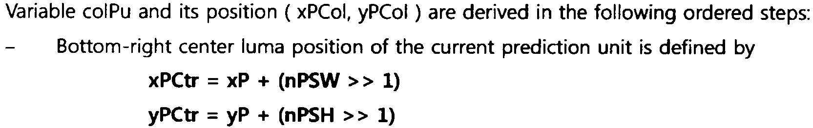
여기서, xPCtr, yPCtr은 시간적 참조 블록에 대해 특정되는 좌표를 나타낼 수 있다. xP, yP는 현재 블록 내의 가장 좌측 상단 픽셀의 좌표를 나타내며, nPSW는 현재 블록의 너비, nPSH는 현재 블록의 높이를 나타낼 수 있다.Here, xPCtr and yPCtr may indicate coordinates specified for a temporal reference block. xP and yP indicate the coordinates of the upper leftmost pixel in the current block, nPSW may indicate the width of the current block, and nPSH may indicate the height of the current block.
시간적 참조 블록이 특정되면, 부호화기 및 복호화기는 상기 시간적 참조 블록 내의 대표 움직임 벡터가 저장되는 최소 단위 블록의 위치를 특정할 수 있다. 이 때, 상기 최소 단위 블록의 위치는 ((xPCtr>>4)<<4 + 8, (yPCtr>>4)<<4 + 8)에 의해 특정될 수 있다. 이 때, colPu는 상기 ((xPCtr>>4)<<4 + 8, (yPCtr>>4)<<4 + 8) 좌표를 포함하는, 참조 픽쳐 내의 예측 유닛으로 특정될 수 있다. 이는 다음과 같이 나타내어질 수 있다.If a temporal reference block is specified, the encoder and decoder can specify the location of a minimum unit block in which a representative motion vector in the temporal reference block is stored. At this time, the position of the minimum unit block may be specified by ((xPCtr >> 4) << 4 + 8, (yPCtr >> 4) << 4 + 8). At this time, colPu may be specified as a prediction unit in a reference picture including the ((xPCtr >> 4) << 4 + 8, (yPCtr >> 4) << 4 + 8) coordinates. This can be represented as follows.
![]()
![]()
이 때, colPu 내의 가장 좌측 상단 좌표는, 다음과 같이 (xPCol, xPCol)로 나타내어질 수 있다.At this time, the top left coordinate in colPu may be expressed as (xPCol, xPCol) as follows.
![]()
![]()
도 19의 1920은 현재 블록의 크기가 64x32인 경우의 동일 위치 블록을 도시한다. 도 19의 1920에서 현재 블록에 대한 시간적 움직임 벡터 예측자는, 도 19의 1910에서와 동일 또는 유사한 방법으로 도출될 수 있다.19 of FIG. 19 shows the same position block when the size of the current block is 64x32. The temporal motion vector predictor for the current block in 1920 of FIG. 19 may be derived in the same or similar manner as in 1910 of FIG. 19.
일례로, 시간적 움직임 벡터 예측자를 도출하기 위해 선택되는 소정의 위치의 블록은 동일 위치 블록의 좌측 상단 센터 블록(0번 블록)일 수 있다. 이 때, 부호화기 및 복호화기는 상기 좌측 상단 센터 블록(0번 블록)을 현재 블록에 대한 시간적 참조 블록으로 선택할 수 있다. 다른 예로, 시간적 움직임 벡터 예측자를 도출하기 위해 선택되는 소정의 위치의 블록은 동일 위치 블록의 우측 상단 센터 블록(1번 블록)일 수도 있다. 이 때, 부호화기 및 복호화기는 상기 우측 상단 센터 블록(1번 블록)을 현재 블록에 대한 시간적 참조 블록으로 선택할 수 있다. 또 다른 예로, 시간적 움직임 벡터 예측자를 도출하기 위해 선택되는 소정의 위치의 블록은 동일 위치 블록의 좌측 하단 센터 블록(2번 블록)일 수도 있다. 이 때, 부호화기 및 복호화기는 상기 좌측 하단 센터 블록(2번 블록)을 현재 블록에 대한 시간적 참조 블록으로 선택할 수 있다. 또 다른 예로, 시간적 움직임 벡터 예측자를 도출하기 위해 선택되는 소정의 위치의 블록은 동일 위치 블록의 우측 하단 센터 블록(3번 블록)일 수도 있다. 이 때, 부호화기 및 복호화기는 상기 우측 하단 센터 블록(3번 블록)을 현재 블록에 대한 시간적 참조 블록으로 선택할 수 있다. 상술한 각각의 예에서, 선택된 시간적 참조 블록의 움직임 벡터는 현재 블록에 대한 시간적 움직임 벡터 예측자로 사용될 수 있다.For example, a block at a predetermined position selected to derive a temporal motion vector predictor may be the upper left center block (block 0) of the same position block. At this time, the encoder and the decoder may select the upper left center block (block 0) as a temporal reference block for the current block. As another example, a block at a predetermined position selected to derive a temporal motion vector predictor may be the upper right center block (block 1) of the same position block. At this time, the encoder and decoder may select the upper right center block (block 1) as a temporal reference block for the current block. As another example, a block at a predetermined position selected to derive a temporal motion vector predictor may be a lower left center block (block 2) of the same position block. At this time, the encoder and decoder may select the lower left center block (block 2) as a temporal reference block for the current block. As another example, a block at a predetermined position selected to derive a temporal motion vector predictor may be a lower right center block (block 3) of the same position block. At this time, the encoder and decoder may select the lower right center block (block 3) as a temporal reference block for the current block. In each of the examples described above, the motion vector of the selected temporal reference block can be used as a temporal motion vector predictor for the current block.
도 19의 1930은 현재 블록의 크기가 64x64인 경우의 동일 위치 블록을 도시한다. 도 19의 1930을 참조하면, 일례로, 시간적 움직임 벡터 예측자를 도출하기 위해 선택되는 소정의 위치의 블록은 동일 위치 블록의 좌측 상단 블록(4번 블록)일 수 있다. 즉, 부호화기 및 복호화기는 상기 좌측 상단 블록(4번 블록)을 현재 블록에 대한 시간적 참조 블록으로 선택할 수 있다. 이 경우에는, 좌측 상단 블록(4번 블록)의 움직임 벡터가 시간적 움직임 벡터 예측자로 사용될 수 있다.1930 of FIG. 19 shows the same position block when the size of the current block is 64x64. Referring to 1930 of FIG. 19, as an example, a block at a predetermined position selected to derive a temporal motion vector predictor may be an upper left block (block 4) of the same position block. That is, the encoder and the decoder may select the upper left block (block 4) as a temporal reference block for the current block. In this case, the motion vector of the upper left block (block 4) can be used as a temporal motion vector predictor.
다른 예로, 시간적 움직임 벡터 예측자를 도출하기 위해 선택되는 소정의 위치의 블록은 동일 위치 블록의 우측 하단 블록(5번 블록)일 수 있다. 즉, 부호화기 및 복호화기는 상기 우측 하단 블록(5번 블록)을 현재 블록에 대한 시간적 참조 블록으로 선택할 수 있다. 이 경우에는, 우측 하단 블록(5번 블록)의 움직임 벡터가 시간적 움직임 벡터 예측자로 사용될 수 있다.As another example, a block at a predetermined position selected to derive a temporal motion vector predictor may be a lower right block (block 5) of the same position block. That is, the encoder and the decoder may select the lower right block (block 5) as a temporal reference block for the current block. In this case, the motion vector of the lower right block (block 5) can be used as a temporal motion vector predictor.
일 실시예로, 우측 하단 블록(5번 블록)이 시간적 참조 블록으로 사용되고, 저장 단위 블록 내의 우측 하단에 위치한 최소 단위 블록의 움직임 정보가 대표 움직임 정보로 사용되는 경우를 가정한다. 이 때, colPu를 유도하는 방법의 구체적인 실시예는 다음과 같다.In one embodiment, it is assumed that the lower right block (block 5) is used as a temporal reference block, and the motion information of the smallest unit block located at the lower right in the storage unit block is used as representative motion information. At this time, a specific embodiment of a method for deriving colPu is as follows.
부호화기 및 복호화기는 동일 위치 블록 내의 우측 하단 블록을 시간적 참조 블록으로 선택할 수 있다. 이 때, 시간적 참조 블록의 위치는 현재 블록 및 동일 위치 블록에 포함된 픽셀의 좌표에 의해 특정될 수 있고, 상기 우측 하단 블록은 (xP+nPSW-1, yP+nPSW-1)에 의해 특정될 수 있다. 이는 다음과 같이 나타내어질 수 있다.The encoder and decoder may select a lower right block in the same location block as a temporal reference block. At this time, the position of the temporal reference block may be specified by the coordinates of the pixels included in the current block and the same position block, and the lower right block may be specified by (xP + nPSW-1, yP + nPSW-1). Can be. This can be represented as follows.
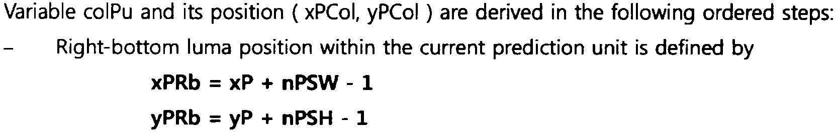
여기서, xPRb, yPRb는 시간적 참조 블록에 대해 특정되는 좌표를 나타낼 수 있다.Here, xPRb and yPRb may indicate coordinates specified for a temporal reference block.
시간적 참조 블록이 특정되면, 부호화기 및 복호화기는 상기 시간적 참조 블록 내의 대표 움직임 벡터가 저장되는 최소 단위 블록의 위치를 특정할 수 있다. 이 때, 상기 최소 단위 블록의 위치는 ((xPRb>>4)<<4 + 12, (yPRb>>4)<<4 + 12)에 의해 특정될 수 있다. 이 때, colPu는 상기 ((xPRb>>4)<<4 + 12, (yPRb>>4)<<4 + 12) 좌표를 포함하는, 참조 픽쳐 내의 예측 유닛으로 특정될 수 있다. 이는 다음과 같이 나타내어질 수 있다.If a temporal reference block is specified, the encoder and decoder can specify the location of a minimum unit block in which a representative motion vector in the temporal reference block is stored. At this time, the location of the minimum unit block may be specified by ((xPRb >> 4) << 4 + 12, (yPRb >> 4) << 4 + 12). At this time, colPu may be specified as a prediction unit in a reference picture including the ((xPRb >> 4) << 4 + 12, (yPRb >> 4) << 4 + 12) coordinates. This can be represented as follows.
![]()
![]()
이 때, colPu 내의 가장 좌측 상단 좌표는, 다음과 같이 (xPCol, xPCol)로 나타내어질 수 있다.At this time, the top left coordinate in colPu may be expressed as (xPCol, xPCol) as follows.
![]()
![]()
도 20은 시간적 움직임 벡터 예측자 도출 방법의 또 다른 실시예를 개략적으로 나타내는 개념도이다.20 is a conceptual diagram schematically showing another embodiment of a method for deriving a temporal motion vector predictor.
도 20을 참조하면, 현재 픽쳐(2010)는 현재 부호화/복호화 대상 픽쳐를 나타내고, 현재 픽쳐(2010)는 현재 블록(2020)을 포함할 수 있다. 상기 현재 블록(2020)에 대한 시간적 움직임 벡터 예측자는, 참조 픽쳐(2030)로부터 도출될 수 있다.Referring to FIG. 20, the
상기 참조 픽쳐(2030)를 구성하는 각각의 블록은 저장 단위 블록을 나타낼 수 있다. 즉, 참조 픽쳐(2030)를 구성하는 각각의 블록은 움직임 정보가 압축되어 저장되는 단위를 나타낼 수 있으며, 참조 픽쳐(2030)를 구성하는 각각의 블록에는 하나의 움직임 정보가 저장되어 있을 수 있다. 일례로, 상기 저장 단위 블록의 크기는 16x16일 수 있다.Each block constituting the
상기 참조 픽쳐(2030)는 현재 블록에 대한 동일 위치 블록(2040)을 포함할 수 있다. 부호화기 및 복호화기는 동일 위치 블록(2040) 내의 소정의 위치의 저장 단위 블록을 현재 블록(2020)에 대한 시간적 참조 블록으로 선택할 수 있으며, 상기 시간적 참조 블록의 위치는 현재 블록(2020)에 대한 시간적 움직임 벡터 예측자의 위치에 해당될 수 있다.The
일 실시예로, 시간적 움직임 벡터 예측자를 도출하기 위해 선택되는 소정의 위치의 블록은, 동일 위치 블록(2040)의 좌측 상단 센터 블록(2050)일 수 있다. 즉, 부호화기 및 복호화기는 상기 좌측 상단 센터 블록(2050)을 현재 블록(2020)에 대한 시간적 참조 블록으로 선택할 수 있다. 이 경우에는, 좌측 상단 센터 블록(2050)의 움직임 벡터가 현재 블록(2020)에 대한 시간적 움직임 벡터 예측자로 사용될 수 있다.In one embodiment, a block at a predetermined position selected to derive a temporal motion vector predictor may be the upper
다른 실시예로, 시간적 움직임 벡터 예측자를 도출하기 위해 선택되는 소정의 위치의 블록은, 좌측 상단 센터 블록(2050)이 아닌, 동일 위치 블록(2040)의 우측 하단 센터 블록(2060)일 수 있다. 즉, 부호화기 및 복호화기는 상기 우측 하단 센터 블록(2060)을 현재 블록에 대한 시간적 참조 블록으로 선택할 수 있다. 이 경우에는, 우측 하단 센터 블록(2060)의 움직임 벡터가 현재 블록(2020)에 대한 시간적 움직임 벡터 예측자로 사용될 수 있다.In another embodiment, a block at a predetermined position selected to derive a temporal motion vector predictor may be the lower
도 21은 시간적 움직임 벡터 예측자 도출 방법의 또 다른 실시예를 개략적으로 나타내는 개념도이다. 도 21의 2110 및 2120은 각각 현재 블록 및 동일 위치 블록이 오버랩(overlap)되어 나타내어진 블록을 도시한다.21 is a conceptual diagram schematically showing another embodiment of a method for deriving a temporal motion vector predictor. 2110 and 2120 of FIG. 21 respectively show a block in which the current block and the co-located block overlap each other.
도 21에서, 동일 위치 블록을 구성하는 각각의 블록은 저장 단위 블록을 나타낼 수 있다. 즉, 동일 위치 블록 내의 각각의 블록은 움직임 정보가 압축되어 저장되는 단위를 나타낼 수 있으며, 동일 위치 블록 내의 각각의 블록에는 하나의 움직임 정보가 저장되어 있을 수 있다. 도 21의 실시예에서는, 설명의 편의를 위해 움직임 정보의 저장 단위, 즉 저장 단위 블록의 크기는 16x16이고, 현재 블록 및 동일 위치 블록의 크기는 64x64라 가정한다.In FIG. 21, each block constituting the same location block may represent a storage unit block. That is, each block in the same location block may represent a unit in which motion information is compressed and stored, and one motion information may be stored in each block in the same location block. In the embodiment of FIG. 21, it is assumed that the size of the storage unit of motion information, that is, the storage unit block is 16x16, and the size of the current block and the co-located block is 64x64 for convenience of description.
부호화기 및 복호화기는 도 17 내지 도 20의 실시예에서 상술한 바와 같이, 고정된 소정의 위치의 블록을 현재 블록에 대한 시간적 참조 블록으로 선택할 수 있으며, 이 경우, 선택된 시간적 참조 블록의 움직임 벡터가 시간적 움직임 벡터 예측자로 사용될 수 있다. 그러나, 상술한 도 17 내지 도 20의 실시예에서, 시간적 움직임 벡터 예측자를 도출하기 위해 선택되는 시간적 참조 블록은 가용한 움직임 정보를 포함하지 않을 수 있다. 시간적 참조 블록이 가용한 움직임 정보를 포함하지 않는 경우로는, 상기 시간적 참조 블록이 인트라 모드로 코딩된 경우 및 상기 시간적 참조 블록에 대응하는 참조 픽쳐 리스트에 유효한(available) 움직임 벡터가 존재하지 않는 경우 등이 있을 수 있다.As described above in the embodiments of FIGS. 17 to 20, the encoder and decoder may select a block at a predetermined predetermined position as a temporal reference block for the current block, in which case, the motion vector of the selected temporal reference block is temporal Can be used as a motion vector predictor. However, in the above-described embodiments of FIGS. 17 to 20, the temporal reference block selected to derive the temporal motion vector predictor may not include available motion information. When the temporal reference block does not include available motion information, when the temporal reference block is coded in the intra mode and when there is no motion vector available in the reference picture list corresponding to the temporal reference block There may be a back.
도 9에서 상술한 바와 같이, 시간적 참조 블록이 가용한 움직임 정보를 포함하지 않는 경우에도, 상기 시간적 참조 블록에 대해, (0,0)의 움직임 벡터가 메모리에 저장되어 있을 수 있다. 이 때, 부호화기 및 복호화기는 (0,0)의 움직임 벡터를 시간적 움직임 벡터 예측자로 결정할 수도 있다. 그러나, 이 경우에는 동일 위치 블록 내에 가용한 움직임 정보가 저장된 저장 단위 블록이 존재하는 경우에도, (0,0)의 움직임 벡터가 시간적 움직임 벡터 예측자로 결정되어, 부정확한 움직임 정보가 사용된다는 문제점이 발생할 수 있다. 따라서, 가용한 움직임 정보를 갖는 시간적 참조 블록을 선택하여 시간적 움직임 벡터 예측자를 결정하는, 시간적 움직임 벡터 예측자 도출 방법이 제공될 수 있다.As described above in FIG. 9, even when the temporal reference block does not include available motion information, a motion vector of (0,0) may be stored in the memory for the temporal reference block. At this time, the encoder and decoder may determine a motion vector of (0,0) as a temporal motion vector predictor. However, in this case, even if there is a storage unit block in which available motion information is stored in the same location block, the motion vector of (0,0) is determined as a temporal motion vector predictor, so that the incorrect motion information is used. Can occur. Accordingly, a method for deriving a temporal motion vector predictor by determining a temporal motion vector predictor by selecting a temporal reference block having available motion information may be provided.
일 실시예로 부호화기 및 복호화기는 동일 위치 블록 내의 소정의 복수의 저장 단위 블록(이하, 시간적 참조 블록 후보라 함. 시간적 참조 블록의 움직임 벡터는 시간적 움직임 벡터 예측자로 사용될 수 있으므로, 상기 시간적 참조 블록 후보는 시간적 움직임 벡터 예측자 후보로 불릴 수도 있음.)을 소정의 순서로 스캔하면서, 스캔되는 저장 단위 블록이 가용한 움직임 정보를 갖는지(예를 들어, 상기 시간적 참조 블록 후보가 인트라 모드로 코딩된 블록인지, 상기 시간적 참조 블록 후보에 대응하는 참조 픽쳐 리스트에 유효한(available) 움직임 벡터가 존재하는지) 여부를 체크할 수 있다. 이 때, 부호화기 및 복호화기는 가용한 움직임 정보를 갖는 시간적 참조 블록 후보 중에서, 스캔 순서가 가장 빠른 후보를 현재 블록에 대한 시간적 참조 블록으로 선택할 수 있으며, 선택된 블록의 움직임 벡터를 시간적 움직임 벡터 예측자로 사용할 수 있다. 즉, 부호화기 및 복호화기는 가용한 움직임 정보를 갖는 시간적 참조 블록 후보를 찾을 때까지 상기 스캔을 수행할 수 있으며, 상기 조건을 충족시키는 첫 번째 시간적 참조 블록 후보의 움직임 벡터를, 현재 블록에 대한 시간적 움직임 벡터 예측자로 결정할 수 있다.In one embodiment, the encoder and decoder are a plurality of storage unit blocks in the same location block (hereinafter referred to as temporal reference block candidates. Since the motion vector of the temporal reference block can be used as a temporal motion vector predictor, the temporal reference block candidate May be referred to as a temporal motion vector predictor candidate.) In a predetermined order, whether the scanned storage unit block has available motion information (eg, a block in which the temporal reference block candidate is coded in intra mode) Cognitively, it is possible to check whether a valid motion vector exists in a reference picture list corresponding to the temporal reference block candidate. At this time, the encoder and the decoder may select a candidate having the fastest scan order as a temporal reference block for the current block among temporal reference block candidates having available motion information, and use the motion vector of the selected block as a temporal motion vector predictor Can be. That is, the encoder and the decoder can perform the scan until a temporal reference block candidate with available motion information is found, and the motion vector of the first temporal reference block candidate that satisfies the above condition is temporally moved with respect to the current block. It can be determined as a vector predictor.
만일, 스캔 대상이 되는, 시간적 참조 블록 후보 모두가 가용한 움직임 정보를 포함하지 않으면(예를 들어, 시간적 참조 블록 후보 모두가 인트라 모드로 코딩되거나 가용하지 않은 경우), 부호화기 및 복호화기는 스캔 순서상 첫 번째 시간적 참조 블록 후보(스캔의 우선 순위가 가장 높은 시간적 참조 블록 후보)를 현재 블록에 대한 시간적 참조 블록으로 결정할 수 있다. 이 때, 일례로, 선택된 시간적 참조 블록에는 (0,0)의 움직임 벡터가 저장되어 있을 수 있으며, (0,0)의 움직임 벡터가 시간적 움직임 벡터 예측자로 사용될 수 있다.If all of the temporal reference block candidates to be scanned do not include available motion information (for example, when all of the temporal reference block candidates are coded or not available in the intra mode), the encoder and decoder are in the scan order. The first temporal reference block candidate (the temporal reference block candidate having the highest priority of scan) may be determined as a temporal reference block for the current block. At this time, as an example, a motion vector of (0,0) may be stored in the selected temporal reference block, and a motion vector of (0,0) may be used as a temporal motion vector predictor.
시간적 참조 블록 후보 및 스캔 순서는 다양하게 정해질 수 있다. 도 21의 각 저장 단위 블록에 표시된 번호는 상기 스캔 순서를 나타낼 수 있다.The temporal reference block candidate and scan order may be variously determined. The number displayed on each storage unit block in FIG. 21 may indicate the scan order.
도 21의 2110을 참조하면, 부호화기 및 복호화기는 현재 블록에 대응하는 동일 위치 블록 내의 저장 단위 블록 중에서 4개의 블록을 시간적 참조 블록 후보로 사용할 수 있다. 여기서, 상기 4개의 블록은 좌측 상단 센터 블록(0번 블록), 우측 상단 센터 블록(1번 블록), 우측 하단 센터 블록(2번 블록), 좌측 하단 센터 블록(3번 블록)일 수 있다.Referring to 2110 of FIG. 21, the encoder and the decoder may use four blocks among storage unit blocks in the same location block corresponding to the current block as temporal reference block candidates. Here, the four blocks may be the upper left center block (block 0), the upper right center block (block 1), the lower right center block (block 2), and the lower left center block (block 3).
일례로, 부호화기 및 복호화기는 0번 블록->1번 블록->2번 블록->3번 블록의 순서로 스캔을 수행할 수 있다. 시간적 참조 블록 후보를 스캔하는 순서는 도 21의 2110에 도시된 번호 순서와 다르게 정해질 수도 있다. 예를 들어, 부호화기 및 복호화기는 2번 블록->3번 블록->0번 블록->1번 블록의 순서로 스캔을 수행할 수도 있다.For example, the encoder and decoder may perform a scan in the order of 0 block-> 1 block-> 2 block-> 3 block. The order of scanning temporal reference block candidates may be determined differently from the number order shown in 2110 of FIG. 21. For example, the encoder and decoder may perform a scan in the order of block 2-> block 3-> block 0->
도 21의 2120을 참조하면, 부호화기 및 복호화기는 현재 블록에 대응하는 동일 위치 블록 내의 저장 단위 블록 중에서 16개의 블록을 시간적 참조 블록 후보로 사용할 수 있다.Referring to 2120 of FIG. 21, the encoder and the decoder may use 16 blocks among storage unit blocks in the same location block corresponding to the current block as temporal reference block candidates.
일례로, 부호화기 및 복호화기는 0번 블록->1번 블록->2번 블록->3번 블록->4번 블록->5번 블록->6번 블록->7번 블록->8번 블록->9번 블록->10번 블록->11번 블록->12번 블록->13번 블록->14번 블록->15번 블록의 순서로 스캔을 수행할 수 있다. 시간적 참조 블록 후보를 스캔하는 순서는 도 21의 2120에 도시된 번호 순서와 다르게 정해질 수도 있다. 예를 들어, 부호화기 및 복호화기는 2번 블록->3번 블록->0번 블록->1번 블록->10번 블록->11번 블록->12번 블록->13번 블록->14번 블록->15번 블록->4번 블록->5번 블록->6번 블록->7번 블록->8번 블록->9번 블록의 순서로 스캔을 수행할 수도 있다.As an example, the encoder and decoder are 0 block-> 1 block-> 2 block-> 3 block-> 4 block-> 5 block-> 6 block-> 7 block-> 8 block -> The scan can be performed in the order of Block 9-> Block 10-> Block 11-> Block 12-> Block 13-> Block 14->
시간적 참조 블록 후보 및/또는 시간적 움직임 벡터 예측자 후보의 위치는 현재 블록 및 동일 위치 블록의 내부에 한정되지 않고, 현재 블록 및/또는 동일 위치 블록의 경계 외부에 존재할 수도 있다. 또한, 현재 블록 및/또는 동일 위치 블록의 외부에 존재하는 시간적 참조 블록 후보의 스캔 순서(우선 순위)가, 현재 블록 및/또는 동일 위치 블록의 내부에 존재하는 시간적 참조 블록 후보의 스캔 순서(우선 순위)보다 더 빠를(높을) 수 있다. 이에 대한 실시예는 도 22에서 후술하기로 한다.The position of the temporal reference block candidate and / or temporal motion vector predictor candidate is not limited to the inside of the current block and the co-located block, but may be outside the boundary of the current block and / or the co-located block. Also, the scan order (priority) of temporal reference block candidates existing outside the current block and / or co-located block is the scan order (priority) of temporal reference block candidates existing inside the current block and / or co-located block. Ranking). An embodiment of this will be described later in FIG. 22.
시간적 참조 블록 후보(또는 시간적 움직임 벡터 예측자 후보)의 개수와 위치 및 스캔 순서는 상술한 실시예에 한정되지 않으며, 구현 및/또는 필요에 따라 다르게 정해질 수 있다. 또한 예를 들어, 현재 블록 및 동일 위치 블록의 크기가 32x32이고 저장 단위 블록의 크기가 16x16인 경우, 시간적 참조 블록 후보 및/또는 시간적 움직임 벡터 예측자 후보의 최대 개수는 4개일 수 있다. 또한, 현재 블록 및 동일 위치 블록의 크기가 저장 단위 블록의 크기보다 작은 경우에는, 상술한 스캔 방법이 사용되지 않을 수 있다.The number and location of the temporal reference block candidates (or temporal motion vector predictor candidates) and the scan order are not limited to the above-described embodiments, and may be differently determined according to implementation and / or needs. Also, for example, when the size of the current block and the co-located block is 32x32 and the size of the storage unit block is 16x16, the maximum number of temporal reference block candidates and / or temporal motion vector predictor candidates may be four. Also, when the sizes of the current block and the co-located block are smaller than the size of the storage unit block, the above-described scan method may not be used.
도 22는 시간적 움직임 벡터 예측자 도출 방법의 또 다른 실시예를 개략적으로 나타내는 개념도이다. 도 22의 2210 및 2220은 각각 현재 블록 및 동일 위치 블록이 오버랩(overlap)되어 나타내어진 블록을 도시한다.22 is a conceptual diagram schematically showing another embodiment of a method for deriving a temporal motion vector predictor. 2210 and 2220 of FIG. 22 show blocks represented by overlapping of a current block and a co-located block, respectively.
도 22에서, 동일 위치 블록을 구성하는 각각의 블록은 저장 단위 블록을 나타낼 수 있다. 도 22에서, 동일 위치 블록을 구성하는 각각의 블록은 저장 단위 블록을 나타낼 수 있다. 즉, 동일 위치 블록 내의 각각의 블록은 움직임 정보가 압축되어 저장되는 단위를 나타낼 수 있으며, 동일 위치 블록 내의 각각의 블록에는 하나의 움직임 정보가 저장되어 있을 수 있다. 도 21의 실시예에서는, 설명의 편의를 위해 움직임 정보의 저장 단위, 즉 저장 단위 블록의 크기는 16x16이고, 현재 블록 및 동일 위치 블록의 크기는 64x64라 가정한다.In FIG. 22, each block constituting the same location block may represent a storage unit block. In FIG. 22, each block constituting the same location block may represent a storage unit block. That is, each block in the same location block may represent a unit in which motion information is compressed and stored, and one motion information may be stored in each block in the same location block. In the embodiment of FIG. 21, it is assumed that the size of the storage unit of motion information, that is, the storage unit block is 16x16, and the size of the current block and the co-located block is 64x64 for convenience of description.
상술한 바와 같이, 부호화기 및 복호화기는 동일 위치 블록의 내부 및/또는 외부에 위치한 저장 단위 블록을 현재 블록에 대한 시간적 참조 블록으로 선택할 수 있다. 부호화기 및 복호화기는 선택된 시간적 참조 블록의 움직임 벡터를 도출할 수 있고, 도출된 움직임 벡터를 시간적 움직임 벡터 예측자로 결정할 수 있다. 이 때, 부호화기 및 복호화기는 상기 시간적 참조 블록과 동일한 움직임 정보를 갖는, 참조 픽쳐 내의 예측 유닛(colPu)으로부터 시간적 움직임 정보 예측자를 도출할 수도 있다.As described above, the encoder and the decoder may select a storage unit block located inside and / or outside the same location block as a temporal reference block for the current block. The encoder and decoder can derive a motion vector of the selected temporal reference block, and determine the derived motion vector as a temporal motion vector predictor. At this time, the encoder and decoder may derive a temporal motion information predictor from a prediction unit (colPu) in a reference picture, which has the same motion information as the temporal reference block.
일 실시예로 도 22의 2210을 참조하면, 부호화기 및 복호화기는 우측 하단 코너 블록(2214, 0번 블록) 및 좌측 상단 센터 블록(2212, 1번 블록)을 현재 블록에 대한 시간적 참조 블록 후보 및/또는 시간적 움직임 벡터 예측자 후보로 사용할 수 있다. 이 때, 부호화기 및 복호화기는 상기 시간적 참조 블록 후보를 우측 하단 코너 블록(2214) -> 좌측 상단 센터 블록(2212)의 순서로 스캔하여, 유효한(available) 첫 번째 블록(스캔의 우선 순위가 높은 블록)의 움직임 벡터를 현재 블록에 대한 시간적 움직임 벡터 예측자로 사용할 수 있다.Referring to 2210 of FIG. 22 as an embodiment, the encoder and decoder are temporal reference block candidates for the current block and / or the lower right corner block (
우선, 부호화기 및 복호화기는 우측 하단 코너 블록(2214)이 유효한지 여부를 체크할 수 있다. 우측 하단 코너 블록(2214)이 유효하지 않은(not available) 경우의 예로서, 우측 하단 코너 블록(2214)이 가용한 움직임 정보를 포함하지 않는 경우, 우측 하단 코너 블록(2214) 및/또는 이에 대응하는 colPu가 인트라 모드로 코딩된 경우 및 상기 colPu가 유효하지 않은 경우 등이 있을 수 있다.First, the encoder and decoder can check whether the lower
우측 하단 코너 블록(2214)이 유효한 경우, 부호화기 및 복호화기는 상기 우측 하단 코너 블록(2214)을 시간적 참조 블록으로 선택할 수 있다. 이 때에는, 우측 하단 코너 블록(2214)의 움직임 벡터가 시간적 움직임 벡터 예측자로 결정될 수 있다. 우측 하단 코너 블록(2214)이 유효하지 않은 경우, 부호화기 및 복호화기는 좌측 상단 센터 블록(2212, 1번 블록)을 시간적 참조 블록으로 선택할 수 있다. 이 때에는, 좌측 상단 센터 블록(2212)의 움직임 벡터가 시간적 움직임 벡터 예측자로 결정될 수 있다.When the lower
상술한 바와 같이, 우측 하단 코너 블록(2214) 및 좌측 상단 센터 블록(2212)이 시간적 참조 블록 후보 및/또는 시간적 움직임 벡터 예측자 후보로 사용되는 경우, colPu를 유도하는 방법의 구체적인 실시예는 다음과 같다. 후술되는 실시예에서는, 저장 단위 블록 내의 가장 좌측 상단에 위치한 최소 단위 블록의 움직임 정보가 대표 움직임 정보로 사용된다고 가정한다.As described above, when the lower
우선, 부호화기 및 복호화기는 우측 하단 코너 블록(2214)에 대응하는 colPu를 도출할 수 있다. 이를 위해, 부호화기 및 복호화기는 현재 블록 및/또는 동일 위치 블록에 포함된 픽셀의 좌표에 의해, 우측 하단 코너 블록(2214)을 특정할 수 있다. 이 때, 우측 하단 코너 블록(2214)은 (xP+nPSW, yP+nPSW)의 좌표에 의해 특정될 수 있다. 이는 다음과 같이 나타내어질 수 있다.First, the encoder and decoder can derive colPu corresponding to the lower

여기서, xPRb, yPRb는 시간적 참조 블록에 대해 특정되는 좌표를 나타낼 수 있다. xP, yP는 현재 블록 내의 가장 좌측 상단 픽셀의 좌표를 나타내며, nPSW는 현재 블록의 너비, nPSH는 현재 블록의 높이를 나타낼 수 있다.Here, xPRb and yPRb may indicate coordinates specified for a temporal reference block. xP and yP indicate the coordinates of the upper leftmost pixel in the current block, nPSW may indicate the width of the current block, and nPSH may indicate the height of the current block.
우측 하단 코너 블록(2214)이 특정되면, 부호화기 및 복호화기는 대표 움직임 벡터가 저장되는, 우측 하단 코너 블록(2214) 내의 최소 단위 블록의 위치를 특정할 수 있다. 여기서, 상기 최소 단위 블록의 위치는 ((xPRb>>4)<<4, (yPRb>>4)<<4)의 좌표에 의해 특정될 수 있다. 이 때, colPu는 상기 ((xPRb>>4)<<4, (yPRb>>4)<<4) 좌표를 포함하는, 참조 픽쳐 내의 예측 유닛으로 특정될 수 있다. 이는 다음과 같이 나타내어질 수 있다.If the lower
![]()
![]()
여기서, 상기 colPu가 인터 모드로 코딩되고 유효한 경우, 상기 colPu의 움직임 벡터가 현재 블록에 대한 시간적 움직임 벡터 예측자로 사용될 수 있다. 이는 우측 하단 코너 블록(2214)이 시간적 참조 블록으로 선택되는 경우에 해당될 수 있다. 그러나, 상기 colPu가 인트라 모드로 코딩되거나 유효하지 않은 경우, 부호화기 및 복호화기는 현재 블록 및 동일 위치 블록에 포함된 픽셀의 좌표에 의해, 좌측 상단 센터 블록(2212)을 특정할 수 있다. 이 때, 좌측 상단 센터 블록(2212)은 (xP+(nPSW>>1)-1, yP+(nPSW>>1)-1)의 좌표에 의해 특정될 수 있다. 이는 다음과 같이 나타내어질 수 있다.Here, when the colPu is coded in an inter mode and valid, the motion vector of the colPu may be used as a temporal motion vector predictor for the current block. This may be the case when the lower

여기서, xPCtr, yPCtr은 시간적 참조 블록에 대해 특정되는 좌표를 나타낼 수 있다.Here, xPCtr and yPCtr may indicate coordinates specified for a temporal reference block.
좌측 상단 센터 블록(2212)이 특정되면, 부호화기 및 복호화기는 대표 움직임 벡터가 저장되는, 좌측 상단 센터 블록(2212) 내의 최소 단위 블록의 위치를 특정할 수 있다. 여기서, 상기 최소 단위 블록의 위치는 ((xPCtr>>4)<<4, (yPCtr>>4)<<4)의 좌표에 의해 특정될 수 있다. 이 때, colPu는 상기 ((xPCtr>>4)<<4, (yPCtr>>4)<<4) 좌표를 포함하는, 참조 픽쳐 내의 예측 유닛으로 특정될 수 있다. 이는 좌측 상단 센터 블록(2212)이 시간적 참조 블록으로 선택되는 경우에 해당될 수 있으며, 다음과 같이 나타내어질 수 있다.When the upper
![]()
![]()
이 때, colPu 내의 가장 좌측 상단 좌표는, 다음과 같이 (xPCol, xPCol)로 나타내어질 수 있다.At this time, the top left coordinate in colPu may be expressed as (xPCol, xPCol) as follows.
![]()
![]()
다른 실시예로 도 22의 2220을 참조하면, 부호화기 및 복호화기는 우측 하단 코너 블록(2224, 0번 블록) 및 우측 하단 센터 블록(2222, 1번 블록)을 현재 블록에 대한 시간적 참조 블록 후보 및/또는 시간적 움직임 벡터 예측자 후보로 사용할 수 있다. 이 때, 부호화기 및 복호화기는 상기 시간적 참조 블록 후보를 우측 하단 코너 블록(2224) -> 우측 하단 센터 블록(2222)의 순서로 스캔하여, 유효한(available) 첫 번째 블록(스캔의 우선 순위가 높은 블록)의 움직임 벡터를 현재 블록에 대한 시간적 움직임 벡터 예측자로 사용할 수 있다.Referring to 2220 of FIG. 22 as another embodiment, the encoder and the decoder may use the lower right corner block (
우선, 부호화기 및 복호화기는 우측 하단 코너 블록(2224)이 유효한지 여부를 체크할 수 있다. 우측 하단 코너 블록(2224)이 유효하지 않은(not available) 경우의 예로서, 우측 하단 코너 블록(2224)이 가용한 움직임 정보를 포함하지 않는 경우, 우측 하단 코너 블록(2224) 및/또는 이에 대응하는 colPu가 인트라 모드로 코딩된 경우 및 상기 colPu가 유효하지 않은 경우 등이 있을 수 있다.First, the encoder and decoder can check whether the lower
우측 하단 코너 블록(2224)이 유효한 경우, 부호화기 및 복호화기는 상기 우측 하단 코너 블록(2224)을 시간적 참조 블록으로 선택할 수 있다. 이 때에는, 우측 하단 코너 블록(2224)의 움직임 벡터가 시간적 움직임 벡터 예측자로 결정될 수 있다. 우측 하단 코너 블록(2224)이 유효하지 않은 경우, 부호화기 및 복호화기는 우측 하단 센터 블록(2222, 1번 블록)을 시간적 참조 블록으로 선택할 수 있다. 이 때에는, 우측 하단 센터 블록(2222)의 움직임 벡터가 시간적 움직임 벡터 예측자로 결정될 수 있다.When the lower
상술한 바와 같이, 우측 하단 코너 블록(2224) 및 우측 하단 센터 블록(2222)이 시간적 참조 블록 후보 및/또는 시간적 움직임 벡터 예측자 후보로 사용되는 경우, colPu를 유도하는 방법의 구체적인 실시예는 다음과 같다. 후술되는 실시예에서는, 저장 단위 블록 내의 가장 좌측 상단에 위치한 최소 단위 블록의 움직임 정보가 대표 움직임 정보로 사용된다고 가정한다.As described above, when the lower
우선, 부호화기 및 복호화기는 우측 하단 코너 블록(2224)에 대응하는 colPu를 도출할 수 있다. 이를 위해, 부호화기 및 복호화기는 현재 블록 및 동일 위치 블록에 포함된 픽셀의 좌표에 의해, 우측 하단 코너 블록(2224)을 특정할 수 있다. 이 때, 우측 하단 코너 블록(2224)은 (xP+nPSW), yP+nPSW)의 좌표에 의해 특정될 수 있다. 이는 다음과 같이 나타내어질 수 있다.First, the encoder and decoder can derive colPu corresponding to the lower

우측 하단 코너 블록(2224)이 특정되면, 부호화기 및 복호화기는 대표 움직임 벡터가 저장되는, 우측 하단 코너 블록(2224) 내의 최소 단위 블록의 위치를 특정할 수 있다. 여기서, 상기 최소 단위 블록의 위치는 ((xPRb>>4)<<4, (yPRb>>4)<<4)의 좌표에 의해 특정될 수 있다. 이 때, colPu는 상기 ((xPRb>>4)<<4, (yPRb>>4)<<4) 좌표를 포함하는, 참조 픽쳐 내의 예측 유닛으로 특정될 수 있다. 이는 다음과 같이 나타내어질 수 있다.If the lower
![]()
![]()
여기서, 상기 colPu가 인터 모드로 코딩되고 유효한 경우, 상기 colPu의 움직임 벡터가 현재 블록에 대한 시간적 움직임 벡터 예측자로 사용될 수 있다. 이는 우측 하단 코너 블록(2224)이 시간적 참조 블록으로 선택되는 경우에 해당될 수 있다. 그러나, 상기 colPu가 인트라 모드로 코딩되거나 유효하지 않은 경우, 부호화기 및 복호화기는 현재 블록 및 동일 위치 블록에 포함된 픽셀의 좌표에 의해, 우측 하단 센터 블록(2222)을 특정할 수 있다. 이 때, 우측 하단 센터 블록(2222)은 (xP+(nPSW>>1), yP+(nPSW>>1))의 좌표에 의해 특정될 수 있다. 이는 다음과 같이 나타내어질 수 있다.Here, when the colPu is coded in an inter mode and valid, the motion vector of the colPu may be used as a temporal motion vector predictor for the current block. This may be the case when the lower

우측 하단 센터 블록(2222)이 특정되면, 부호화기 및 복호화기는 대표 움직임 벡터가 저장되는, 우측 하단 센터 블록(2222) 내의 최소 단위 블록의 위치를 특정할 수 있다. 여기서, 상기 최소 단위 블록의 위치는 ((xPCtr>>4)<<4, (yPCtr>>4)<<4)의 좌표에 의해 특정될 수 있다. 이 때, colPu는 상기 ((xPCtr>>4)<<4, (yPCtr>>4)<<4) 좌표를 포함하는, 참조 픽쳐 내의 예측 유닛으로 특정될 수 있다. 이는 우측 하단 센터 블록(2222)이 시간적 참조 블록으로 선택되는 경우에 해당될 수 있으며, 다음과 같이 나타내어질 수 있다.When the lower
![]()
![]()
이 때, colPu 내의 가장 좌측 상단 좌표는, 다음과 같이 (xPCol, xPCol)로 나타내어질 수 있다.At this time, the top left coordinate in colPu may be expressed as (xPCol, xPCol) as follows.
![]()
![]()
또 다른 실시예로, 부호화기 및 복호화기는 시간적 참조 블록 후보의 유효성을 체크할 때, 상기 시간적 참조 블록 후보 및/또는 colPu의 위치(또는 좌표)가 현재 블록이 속한 LCU 내의 좌표에 해당되는지 여부를 함께 체크할 수 있다. 시간적 참조 블록 후보 및/또는 colPu의 위치(또는 좌표)가 현재 블록이 속한 LCU에 포함되지 않는 경우, 부호화기 및 복호화기는 상기 시간적 참조 블록 후보 및/또는 colPu를 유효하지 않은 것으로 취급할 수 있다.In another embodiment, the encoder and decoder determine whether a position (or coordinate) of the temporal reference block candidate and / or colPu corresponds to a coordinate in an LCU to which the current block belongs when checking the validity of the temporal reference block candidate. You can check. If the position (or coordinate) of the temporal reference block candidate and / or colPu is not included in the LCU to which the current block belongs, the encoder and decoder may treat the temporal reference block candidate and / or colPu as invalid.
상술한 2210 및 2220의 동일 위치 블록의 실시예들에서, 부호화기 및 복호화기는 우측 하단 코너 블록이 유효한지 여부를 체크할 수 있다. 우측 하단 코너 블록이 유효한 경우에는, 우측 하단 코너 블록의 움직임 벡터가 시간적 움직임 벡터 예측자로 사용되고, 우측 하단 코너 블록이 유효하지 않은 경우에는, 좌측 상단 센터 블록 또는 우측 하단 센터 블록의 움직임 벡터가 시간적 움직임 벡터 예측자로 사용될 수 있다. 이 때, 우측 하단 코너 블록 및/또는 이에 대응되는 colPu의 위치(또는 좌표)가 현재 블록이 속한 LCU의 경계 외부에 있는 경우, 부호화기 및 복호화기는 우측 하단 코너 블록 및/또는 이에 대응되는 colPu가 유효하지 않은 것으로 취급할 수 있다. 즉, 우측 하단 코너 블록 및/또는 이에 대응되는 colPu의 위치(또는 좌표)가 현재 블록이 속한 LCU의 경계 외부에 있는 경우, 부호화기 및 복호화기는 좌측 상단 센터 블록 또는 우측 하단 센터 블록의 움직임 벡터를 시간적 움직임 벡터 예측자로 결정할 수 있다.In the above-described embodiments of the co-located blocks of 2210 and 2220, the encoder and decoder may check whether the lower right corner block is valid. When the lower right corner block is valid, the motion vector of the lower right corner block is used as a temporal motion vector predictor, and when the lower right corner block is invalid, the motion vector of the upper left center block or lower right center block is temporal motion. Can be used as a vector predictor. At this time, if the position (or coordinate) of the lower right corner block and / or the colPu corresponding thereto is outside the boundary of the LCU to which the current block belongs, the encoder and decoder are effective in the lower right corner block and / or the colPu corresponding thereto. You can treat it as not. That is, when the position (or coordinate) of the lower right corner block and / or the corresponding colPu is outside the boundary of the LCU to which the current block belongs, the encoder and decoder temporally move the motion vector of the upper left center block or lower right center block. It can be determined as a motion vector predictor.
상술한 바와 같이 LCU를 기준으로 시간적 참조 블록 후보 및/또는 colPu의 유효성을 체크하는 경우, colPu를 유도하는 방법의 구체적인 실시예는 다음과 같다. 후술되는 실시예에서는, 저장 단위 블록 내의 가장 좌측 상단에 위치한 최소 단위 블록의 움직임 정보가 대표 움직임 정보로 사용된다고 가정한다.When checking the validity of the temporal reference block candidate and / or colPu based on the LCU as described above, a specific embodiment of a method for deriving colPu is as follows. In the embodiment described below, it is assumed that the motion information of the smallest unit block located at the upper left of the storage unit block is used as representative motion information.
우선, 부호화기 및 복호화기는 우측 하단 코너 블록에 대응하는 colPu를 도출할 수 있다. 이는 다음과 같이 나타내어질 수 있다.First, the encoder and decoder can derive colPu corresponding to the lower right corner block. This can be represented as follows.

여기서, 상기 colPu가 인터 모드로 코딩되고 유효하며 현재 블록이 속한 LCU 내의 좌표에 위치하는 경우, 상기 colPu의 움직임 벡터가 현재 블록에 대한 시간적 움직임 벡터 예측자로 사용될 수 있다. 이는 우측 하단 코너 블록이 시간적 참조 블록으로 선택되는 경우에 해당될 수 있다.Here, when the colPu is coded in an inter mode and is valid and is located at a coordinate in an LCU to which the current block belongs, the motion vector of the colPu may be used as a temporal motion vector predictor for the current block. This may be the case when the lower right corner block is selected as a temporal reference block.
그러나, 상기 colPu가 인트라 모드로 코딩되거나, 유효하지 않거나 또는 colPu의 위치(또는 좌표)가 현재 블록이 속한 LCU의 경계 외부에 있는 경우, 부호화기 및 복호화기는 좌측 상단 센터 블록(또는 우측 하단 센터 블록)에 대응하는 colPu를 도출할 수 있다. 이는 상기 좌측 상단 센터 블록(또는 상기 우측 하단 센터 블록)이 시간적 참조 블록으로 선택되는 경우에 해당될 수 있으며, 다음과 같이 나타내어질 수 있다.However, if the colPu is coded in the intra mode, is invalid, or the position (or coordinate) of the colPu is outside the boundary of the LCU to which the current block belongs, the encoder and decoder are in the upper left center block (or lower right center block). It is possible to derive colPu corresponding to. This may correspond to a case where the upper left center block (or the lower right center block) is selected as a temporal reference block, and may be represented as follows.
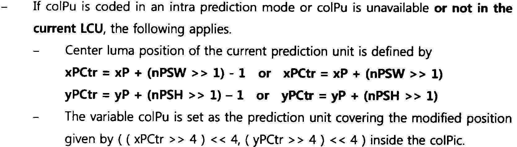
이 때, colPu 내의 가장 좌측 상단 좌표는, 다음과 같이 (xPCol, xPCol)로 나타내어질 수 있다.At this time, the top left coordinate in colPu may be expressed as (xPCol, xPCol) as follows.
![]()
![]()
LCU를 기준으로 시간적 참조 블록 후보 및/또는 colPu의 유효성을 체크하는 경우, colPu를 유도하는 방법의 또 다른 실시예는 다음과 같다.When checking the validity of the temporal reference block candidate and / or colPu based on the LCU, another embodiment of a method for deriving colPu is as follows.
우선, 우측 하단 코너 블록의 위치(또는 좌표)가 현재 블록이 속한 LCU의 내부에 존재하는 경우, 부호화기 및 복호화기는 우측 하단 코너 블록에 대응하는 colPu를 도출할 수 있다. 우측 하단 코너 블록의 위치(또는 좌표)가 현재 블록이 속한 LCU의 경계 외부에 있는 경우, colPu는 유효하지 않은 것으로 처리될 수 있다. 이는 다음과 같이 나타내어질 수 있다.First, when the position (or coordinate) of the lower right corner block exists inside the LCU to which the current block belongs, the encoder and decoder can derive colPu corresponding to the lower right corner block. When the position (or coordinate) of the lower right corner block is outside the boundary of the LCU to which the current block belongs, colPu may be treated as invalid. This can be represented as follows.

여기서, 상기 colPu가 인터 모드로 코딩되고 유효한 경우, 상기 colPu의 움직임 벡터가 현재 블록에 대한 시간적 움직임 벡터 예측자로 사용될 수 있다. 이는 우측 하단 코너 블록이 시간적 참조 블록으로 선택되는 경우에 해당될 수 있다. 그러나, 상기 colPu가 인트라 모드로 코딩되거나 유효하지 않은 경우, 부호화기 및 복호화기는 우측 하단 센터 블록에 대응하는 colPu를 도출할 수 있다. 이는 상기 상기 우측 하단 센터 블록이 시간적 참조 블록으로 선택되는 경우에 해당될 수 있으며, 다음과 같이 나타내어질 수 있다.Here, when the colPu is coded in an inter mode and valid, the motion vector of the colPu may be used as a temporal motion vector predictor for the current block. This may be the case when the lower right corner block is selected as a temporal reference block. However, if the colPu is coded in the intra mode or is invalid, the encoder and decoder can derive the colPu corresponding to the lower right center block. This may correspond to the case where the lower right center block is selected as a temporal reference block, and may be represented as follows.
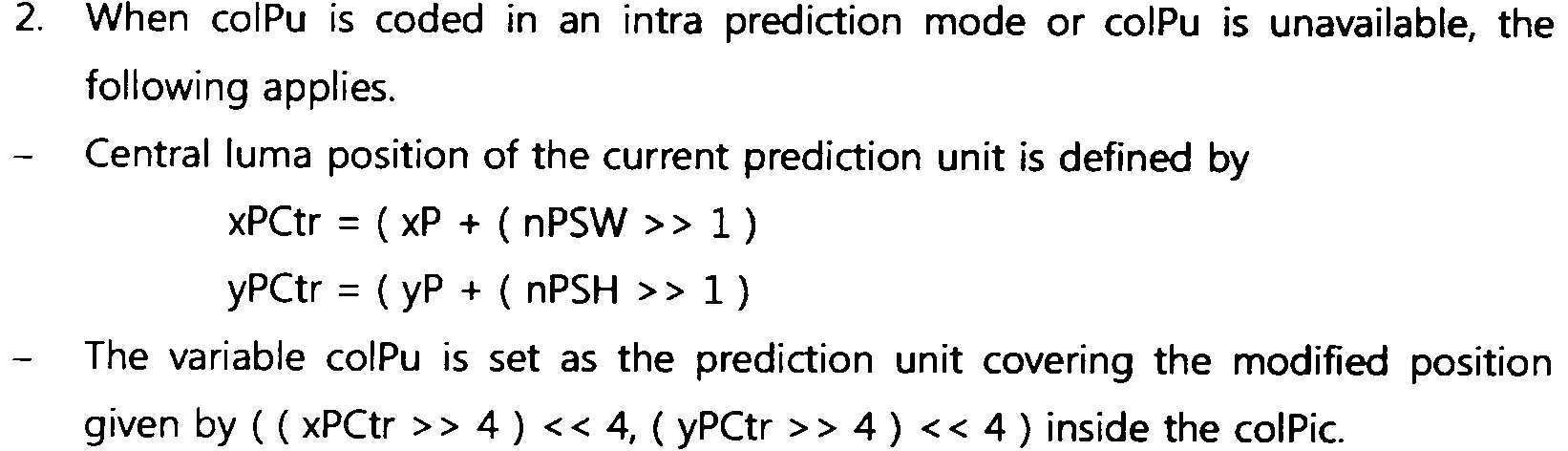
이 때, colPu 내의 가장 좌측 상단 좌표는, 다음과 같이 (xPCol, xPCol)로 나타내어질 수 있다.At this time, the top left coordinate in colPu may be expressed as (xPCol, xPCol) as follows.
![]()
![]()
도 23은 본 발명에 따른 인터 예측 방법의 일 실시예를 개략적으로 나타내는 흐름도이다.23 is a flowchart schematically showing an embodiment of an inter prediction method according to the present invention.
도 23을 참조하면, 부호화기 및 복호화기는 참조 픽쳐의 시간적 움직임 정보를 저장할 수 있다(S2310). 이 때, 부호화기 및 복호화기는 소요되는 메모리의 크기를 감소시키기 위해, 시간적 움직임 정보를 압축하여 저장할 수 있다. 시간적 움직임 정보 압축 방법의 실시예들은 도 7 내지 도 15에서 상술한 바 있으므로, 생략하기로 한다.Referring to FIG. 23, an encoder and a decoder may store temporal motion information of a reference picture (S2310). At this time, the encoder and decoder may compress and store temporal motion information in order to reduce the size of memory required. Embodiments of the temporal motion information compression method have been described above with reference to FIGS. 7 to 15, and thus will be omitted.
또한, 부호화기 및 복호화기는 참조 픽쳐에서, 현재 블록에 대한 시간적 참조 블록을 선택할 수 있다(S2320). 여기서, 시간적 참조 블록은, 시간적 움직임 벡터 예측자로 사용되는 움직임 벡터를 포함하는, 참조 픽쳐 내의 저장 단위 블록을 의미할 수 있다.Also, the encoder and the decoder may select a temporal reference block for the current block from the reference picture (S2320). Here, the temporal reference block may mean a storage unit block in a reference picture including a motion vector used as a temporal motion vector predictor.
상기 시간적 참조 블록의 위치는 현재 블록 및/또는 현재 블록에 대한 동일 위치 블록을 기준으로 정해질 수 있다. 부호화기 및 복호화기는 참조 픽쳐 내의 소정의 위치의 블록을 현재 블록에 대한 시간적 참조 블록으로 선택할 수 있고, 소정의 복수의 시간적 참조 블록 후보 중에서 시간적 참조 블록을 선택할 수도 있다. 선택된 시간적 참조 블록은 블록 자체가 아닌, 상기 시간적 참조 블록에 포함된 픽셀의 좌표로 특정될 수도 있다. 시간적 참조 블록 도출 방법의 실시예들은 도 16 내지 도 22의 실시예에서 상술한 바 있으므로, 생략하기로 한다.The location of the temporal reference block may be determined based on the current block and / or the same location block for the current block. The encoder and decoder may select a block at a predetermined position in the reference picture as a temporal reference block for the current block, or may select a temporal reference block among a plurality of temporal reference block candidates. The selected temporal reference block may be specified not by the block itself, but by coordinates of pixels included in the temporal reference block. Embodiments of the temporal reference block derivation method have been described in the embodiments of FIGS. 16 to 22, and thus will be omitted.
시간적 참조 블록이 선택 및/또는 특정되면, 부호화기 및 복호화기는 상기 시간적 참조 블록을 이용하여, 현재 블록에 대한 시간적 움직임 벡터 예측자를 도출할 수 있다(S2330).If the temporal reference block is selected and / or specified, the encoder and decoder may derive a temporal motion vector predictor for the current block using the temporal reference block (S2330).
부호화기 및 복호화기는 상기 시간적 참조 블록의 움직임 벡터를 도출할 수 있다. 이 때, 도출된 움직임 벡터가 시간적 움직임 벡터 예측자로 결정될 수 있다. 상기 시간적 참조 블록은 저장 단위에 해당될 수 있으므로, 부호화기 및 복호화기는 시간적 참조 블록과 동일한 움직임 정보를 갖는 예측 유닛(예를 들어, colPu)으로부터 시간적 움직임 정보 예측자를 도출할 수도 있다.The encoder and decoder can derive the motion vector of the temporal reference block. At this time, the derived motion vector may be determined as a temporal motion vector predictor. Since the temporal reference block may correspond to a storage unit, the encoder and decoder may derive a temporal motion information predictor from a prediction unit (eg, colPu) having the same motion information as the temporal reference block.
현재 블록에 대한 시간적 움직임 벡터 예측자가 도출되면, 부호화기 및 복호화기는 도출된 시간적 움직임 벡터 예측자를 이용하여, 현재 블록에 대한 인터 예측을 수행할 수 있다(S2340).When the temporal motion vector predictor for the current block is derived, the encoder and the decoder may perform inter prediction on the current block using the derived temporal motion vector predictor (S2340).
상술한 실시예들에서, 방법들은 일련의 단계 또는 블록으로써 순서도를 기초로 설명되고 있지만, 본 발명은 단계들의 순서에 한정되는 것은 아니며, 어떤 단계는 상술한 바와 다른 단계와 다른 순서로 또는 동시에 발생할 수 있다. 또한, 당업자라면 순서도에 나타낸 단계들이 배타적이지 않고, 다른 단계가 포함되거나 순서도의 하나 또는 그 이상의 단계가 본 발명의 범위에 영향을 미치지 않고 삭제될 수 있음을 이해할 수 있을 것이다.In the above-described embodiments, the methods are described based on a flowchart as a series of steps or blocks, but the present invention is not limited to the order of steps, and some steps may occur in a different order or simultaneously with other steps as described above. Can be. In addition, those skilled in the art will understand that the steps shown in the flowcharts are not exclusive, other steps may be included, or one or more steps in the flowchart may be deleted without affecting the scope of the present invention.
상술한 실시예는 다양한 양태의 예시들을 포함한다. 다양한 양태들을 나타내기 위한 모든 가능한 조합을 기술할 수는 없지만, 해당 기술 분야의 통상의 지식을 가진 자는 다른 조합이 가능합을 인식할 수 있을 것이다. 따라서, 본 발명은 이하의 특허청구범위 내에 속하는 모든 다른 교체, 수정 및 변경을 포함한다고 할 것이다.The above-described embodiments include examples of various aspects. It is not possible to describe all possible combinations to represent various aspects, but a person skilled in the art will recognize that other combinations are possible. Accordingly, the present invention will be said to include all other replacements, modifications and changes that fall within the scope of the following claims.
Claims (9)
수신한 영상 정보를 기반으로 현재 블록에 대한 예측 모드를 인터 예측 모드로 도출하는 단계;
상기 현재 블록에 대한 시간적 움직임 벡터 예측자를 도출하는 단계;
상기 시간적 움직임 벡터 예측자를 기반으로 상기 현재 블록의 움직임 벡터를 도출하는 단계;
상기 도출된 움직임 벡터를 기반으로 상기 현재 블록에 대한 예측된 블록을 생성하는 단계; 및
상기 예측된 블록을 기반으로 복원 픽처를 생성하는 단계를 포함하되,
상기 시간적 움직임 벡터 예측자를 도출하는 단계는,
참조 픽처 내에서, 특정 위치를 커버하는 예측 블록을 상기 현재 블록에 대한 참조 예측 유닛(colPu)으로 결정하는 단계; 및
상기 참조 예측 유닛의 움직임 정보를 기반으로 상기 시간적 움직임 벡터 예측자를 도출하는 단계를 포함하고,
상기 특정 위치는 상기 참조 픽처 내에서 상기 현재 블록에 대한 동일 위치 블록의 우측 하단 센터 블록의 좌표를 기반으로 도출되고,
상기 우측 하단 센터 블록의 좌표는 (xPCtr, yPCtr)이고, 여기서 xPCtr=xP+(nPSW>>1), yPCtr=yP+(nPSH>>1)이고, xP, yP는 각각 상기 현재 블록의 x좌표 및 y좌표와 같고, nPSW, nPSH는 각각 상기 현재 블록의 너비 및 높이와 같은 것을 특징으로 하는 영상 디코딩 방법.As a video decoding method performed by the decoding device,
Deriving a prediction mode for the current block as an inter prediction mode based on the received image information;
Deriving a temporal motion vector predictor for the current block;
Deriving a motion vector of the current block based on the temporal motion vector predictor;
Generating a predicted block for the current block based on the derived motion vector; And
And generating a reconstructed picture based on the predicted block,
The step of deriving the temporal motion vector predictor is:
Determining, within a reference picture, a prediction block covering a specific location as a reference prediction unit (colPu) for the current block; And
Deriving the temporal motion vector predictor based on the motion information of the reference prediction unit,
The specific location is derived based on the coordinates of the lower right center block of the same location block for the current block in the reference picture,
The coordinates of the lower right center block are (xPCtr, yPCtr), where xPCtr = xP + (nPSW >> 1), yPCtr = yP + (nPSH >> 1), and xP, yP are the x coordinate and y of the current block, respectively. The same as the coordinates, and nPSW and nPSH are respectively the same as the width and height of the current block.
상기 동일 위치 블록의 우측 하단 코너 블록의 좌표가 상기 현재 블록이 속한 LCU(Largest Coding Unit)의 외부에 위치하는 경우, 상기 특정 위치는 상기 동일 위치 블록의 우측 하단 센터 블록의 좌표를 기반으로 도출되는 것을 특징으로 하는 영상 디코딩 방법.According to claim 1,
When the coordinates of the lower right corner block of the same location block are located outside of a large coding unit (LCU) to which the current block belongs, the specific location is derived based on the coordinates of the lower right center block of the same location block Video decoding method, characterized in that.
상기 우측 하단 코너 블록의 좌표는 (xPRB, yPRB)이고, 여기서 xPRB=xP+nPSW, yPRB=yP+nPSH이고,
상기 yPRB이 상기 LCU 내에 위치하지 않는 경우, 상기 우측 하단 코너 블록의 좌표가 상기 LCU의 외부에 위치하는 것으로 판단되는 것을 특징으로 하는 영상 디코딩 방법.According to claim 2,
The coordinates of the lower right corner block are (xPRB, yPRB), where xPRB = xP + nPSW, yPRB = yP + nPSH,
When the yPRB is not located in the LCU, the coordinates of the lower right corner block are determined to be located outside the LCU.
상기 특정 위치는 ((xPCtr>>4)<<4, (yPCtr>>4)<<4)로 도출되는 것을 특징으로 하는 영상 디코딩 방법.According to claim 1,
The specific position is derived by ((xPCtr >> 4) << 4, (yPCtr >> 4) << 4).
수신한 영상 정보를 기반으로 현재 블록에 대한 예측 모드를 인터 예측 모드로 도출하고. 상기 현재 블록에 대한 시간적 움직임 벡터 예측자를 도출하고, 상기 시간적 움직임 벡터 예측자를 기반으로 상기 현재 블록의 움직임 벡터를 도출하고, 상기 도출된 움직임 벡터를 기반으로 상기 현재 블록에 대한 예측된 블록을 생성하는 예측부; 및
상기 예측된 블록을 기반으로 복원 픽처를 생성하는 가산부를 포함하되,
상기 시간적 움직임 벡터 예측자를 도출함에 있어서, 상기 예측부는 참조 픽처 내에서, 특정 위치를 커버하는 예측 블록을 상기 현재 블록에 대한 참조 예측 유닛(colPu)으로 결정하고, 상기 참조 예측 유닛의 움직임 정보를 기반으로 상기 시간적 움직임 벡터 예측자를 도출하고,
상기 특정 위치는 상기 참조 픽처 내에서 상기 현재 블록에 대한 동일 위치 블록의 우측 하단 센터 블록의 좌표를 기반으로 도출되고,
상기 우측 하단 센터 블록의 좌표는 (xPCtr, yPCtr)이고, 여기서 xPCtr=xP+(nPSW>>1), yPCtr=yP+(nPSH>>1)이고, xP, yP는 각각 상기 현재 블록의 x좌표 및 y좌표와 같고, nPSW, nPSH는 각각 상기 현재 블록의 너비 및 높이와 같은 것을 특징으로 하는 디코딩 장치.In the decoding apparatus for performing video decoding,
Based on the received image information, a prediction mode for the current block is derived as an inter prediction mode. Deriving a temporal motion vector predictor for the current block, deriving a motion vector of the current block based on the temporal motion vector predictor, and generating a predicted block for the current block based on the derived motion vector Prediction unit; And
Includes an adder for generating a reconstructed picture based on the predicted block,
In deriving the temporal motion vector predictor, the prediction unit determines a prediction block covering a specific position in a reference picture as a reference prediction unit (colPu) for the current block, and based on motion information of the reference prediction unit To derive the temporal motion vector predictor,
The specific location is derived based on the coordinates of the lower right center block of the same location block for the current block in the reference picture,
The coordinates of the lower right center block are (xPCtr, yPCtr), where xPCtr = xP + (nPSW >> 1), yPCtr = yP + (nPSH >> 1), and xP, yP are the x coordinate and y of the current block, respectively. The same as the coordinates, nPSW, nPSH decoding device, characterized in that the same as the width and height of the current block, respectively.
현재 블록에 대한 예측 모드를 인터 예측 모드로 결정하는 단계;
상기 현재 블록에 대한 시간적 움직임 벡터 예측자를 도출하는 단계;
상기 시간적 움직임 벡터 예측자를 기반으로 상기 현재 블록의 움직임 벡터를 도출하는 단계;
상기 도출된 움직임 벡터를 기반으로 상기 현재 블록에 대한 예측된 블록을 생성하는 단계;
상기 예측된 블록을 기반으로 레지듀얼 블록을 도출하는 단계; 및
상기 레지듀얼 블록에 관한 정보 및 상기 예측 모드에 대한 정보를 포함하는 비트스트림을 생성하는 단계를 포함하되,
상기 시간적 움직임 벡터 예측자를 도출하는 단계는,
참조 픽처 내에서, 특정 위치를 커버하는 예측 블록을 상기 현재 블록에 대한 참조 예측 유닛(colPu)으로 결정하는 단계; 및
상기 참조 예측 유닛의 움직임 정보를 기반으로 상기 시간적 움직임 벡터 예측자를 도출하는 단계를 포함하고,
상기 특정 위치는 상기 참조 픽처 내에서 상기 현재 블록에 대한 동일 위치 블록의 우측 하단 센터 블록의 좌표를 기반으로 도출되고,
상기 우측 하단 센터 블록의 좌표는 (xPCtr, yPCtr)이고, 여기서 xPCtr=xP+(nPSW>>1), yPCtr=yP+(nPSH>>1)이고, xP, yP는 각각 상기 현재 블록의 x좌표 및 y좌표와 같고, nPSW, nPSH는 각각 상기 현재 블록의 너비 및 높이와 같은 것을 특징으로 하는 영상 인코딩 방법.A video encoding method performed by an encoding device,
Determining a prediction mode for a current block as an inter prediction mode;
Deriving a temporal motion vector predictor for the current block;
Deriving a motion vector of the current block based on the temporal motion vector predictor;
Generating a predicted block for the current block based on the derived motion vector;
Deriving a residual block based on the predicted block; And
Generating a bitstream including information on the residual block and information on the prediction mode,
The step of deriving the temporal motion vector predictor is:
Determining, within a reference picture, a prediction block covering a specific location as a reference prediction unit (colPu) for the current block; And
Deriving the temporal motion vector predictor based on the motion information of the reference prediction unit,
The specific location is derived based on the coordinates of the lower right center block of the same location block for the current block in the reference picture,
The coordinates of the lower right center block are (xPCtr, yPCtr), where xPCtr = xP + (nPSW >> 1), yPCtr = yP + (nPSH >> 1), and xP, yP are the x coordinate and y of the current block, respectively. The same as the coordinates, and nPSW and nPSH are respectively the same as the width and height of the current block.
상기 동일 위치 블록의 우측 하단 코너 블록의 좌표가 상기 현재 블록이 속한 LCU(Largest Coding Unit)의 외부에 위치하는 경우, 상기 특정 위치는 상기 동일 위치 블록의 우측 하단 센터 블록의 좌표를 기반으로 도출되는 것을 특징으로 하는 영상 인코딩 방법.The method of claim 6,
When the coordinates of the lower right corner block of the same location block are located outside of a large coding unit (LCU) to which the current block belongs, the specific location is derived based on the coordinates of the lower right center block of the same location block Video encoding method, characterized in that.
현재 블록에 대한 예측 모드를 인터 예측 모드로 결정하고, 상기 현재 블록에 대한 시간적 움직임 벡터 예측자를 도출하고, 상기 시간적 움직임 벡터 예측자를 기반으로 상기 현재 블록의 움직임 벡터를 도출하고, 상기 도출된 움직임 벡터를 기반으로 상기 현재 블록에 대한 예측된 블록을 생성하는 예측부;
상기 예측된 블록을 기반으로 레지듀얼 블록을 생성하는 감산부; 및
상기 레지듀얼 블록에 관한 정보를 포함하는 비트스트림을 생성하는 엔트로피 인코딩부를 포함하되,
상기 시간적 움직임 벡터 예측자를 도출함에 있어서, 상기 예측부는 참조 픽처 내에서, 특정 위치를 커버하는 예측 블록을 상기 현재 블록에 대한 참조 예측 유닛(colPu)으로 결정하고, 상기 참조 예측 유닛의 움직임 정보를 기반으로 상기 시간적 움직임 벡터 예측자를 도출하고,
상기 특정 위치는 상기 참조 픽처 내에서 상기 현재 블록에 대한 동일 위치 블록의 우측 하단 센터 블록의 좌표를 기반으로 도출되고,
상기 우측 하단 센터 블록의 좌표는 (xPCtr, yPCtr)이고, 여기서 xPCtr=xP+(nPSW>>1), yPCtr=yP+(nPSH>>1)이고, xP, yP는 각각 상기 현재 블록의 x좌표 및 y좌표와 같고, nPSW, nPSH는 각각 상기 현재 블록의 너비 및 높이와 같은 것을 특징으로 하는 인코딩 장치.In the encoding apparatus for performing video encoding,
A prediction mode for a current block is determined as an inter prediction mode, a temporal motion vector predictor for the current block is derived, a motion vector of the current block is derived based on the temporal motion vector predictor, and the derived motion vector A prediction unit that generates a predicted block for the current block based on;
A subtraction unit generating a residual block based on the predicted block; And
An entropy encoding unit for generating a bitstream including information on the residual block,
In deriving the temporal motion vector predictor, the prediction unit determines a prediction block covering a specific position in a reference picture as a reference prediction unit (colPu) for the current block, and based on motion information of the reference prediction unit To derive the temporal motion vector predictor,
The specific location is derived based on the coordinates of the lower right center block of the same location block for the current block in the reference picture,
The coordinates of the lower right center block are (xPCtr, yPCtr), where xPCtr = xP + (nPSW >> 1), yPCtr = yP + (nPSH >> 1), and xP, yP are the x coordinate and y of the current block, respectively. The same as the coordinates, nPSW, nPSH is the encoding device, characterized in that the width and height of the current block, respectively.
Priority Applications (1)
| Application Number | Priority Date | Filing Date | Title |
|---|---|---|---|
| KR1020217002354A KR102287971B1 (en) | 2011-02-09 | 2012-02-09 | Method for encoding and decoding image and device using same |
Applications Claiming Priority (7)
| Application Number | Priority Date | Filing Date | Title |
|---|---|---|---|
| US201161440871P | 2011-02-09 | 2011-02-09 | |
| US61/440,871 | 2011-02-09 | ||
| US201161454567P | 2011-03-20 | 2011-03-20 | |
| US61/454,567 | 2011-03-20 | ||
| US201161476776P | 2011-04-19 | 2011-04-19 | |
| US61/476,776 | 2011-04-19 | ||
| PCT/KR2012/000959 WO2012108700A2 (en) | 2011-02-09 | 2012-02-09 | Method for encoding and decoding image and device using same |
Related Parent Applications (1)
| Application Number | Title | Priority Date | Filing Date |
|---|---|---|---|
| KR1020207001224A Division KR102114282B1 (en) | 2011-02-09 | 2012-02-09 | Method for encoding and decoding image and device using same |
Related Child Applications (1)
| Application Number | Title | Priority Date | Filing Date |
|---|---|---|---|
| KR1020217002354A Division KR102287971B1 (en) | 2011-02-09 | 2012-02-09 | Method for encoding and decoding image and device using same |
Publications (2)
| Publication Number | Publication Date |
|---|---|
| KR20200057798A true KR20200057798A (en) | 2020-05-26 |
| KR102209693B1 KR102209693B1 (en) | 2021-01-29 |
Family
ID=46639066
Family Applications (7)
| Application Number | Title | Priority Date | Filing Date |
|---|---|---|---|
| KR1020217002354A KR102287971B1 (en) | 2011-02-09 | 2012-02-09 | Method for encoding and decoding image and device using same |
| KR1020207001224A KR102114282B1 (en) | 2011-02-09 | 2012-02-09 | Method for encoding and decoding image and device using same |
| KR1020217024620A KR102355509B1 (en) | 2011-02-09 | 2012-02-09 | Method for encoding and decoding image and device using same |
| KR1020137000267A KR101961960B1 (en) | 2011-02-09 | 2012-02-09 | Method for encoding and decoding image and device using same |
| KR1020227002213A KR102450324B1 (en) | 2011-02-09 | 2012-02-09 | Method for encoding and decoding image and device using same |
| KR1020207014188A KR102209693B1 (en) | 2011-02-09 | 2012-02-09 | Method for encoding and decoding image and device using same |
| KR1020197007830A KR102068826B1 (en) | 2011-02-09 | 2012-02-09 | Method for encoding and decoding image and device using same |
Family Applications Before (5)
| Application Number | Title | Priority Date | Filing Date |
|---|---|---|---|
| KR1020217002354A KR102287971B1 (en) | 2011-02-09 | 2012-02-09 | Method for encoding and decoding image and device using same |
| KR1020207001224A KR102114282B1 (en) | 2011-02-09 | 2012-02-09 | Method for encoding and decoding image and device using same |
| KR1020217024620A KR102355509B1 (en) | 2011-02-09 | 2012-02-09 | Method for encoding and decoding image and device using same |
| KR1020137000267A KR101961960B1 (en) | 2011-02-09 | 2012-02-09 | Method for encoding and decoding image and device using same |
| KR1020227002213A KR102450324B1 (en) | 2011-02-09 | 2012-02-09 | Method for encoding and decoding image and device using same |
Family Applications After (1)
| Application Number | Title | Priority Date | Filing Date |
|---|---|---|---|
| KR1020197007830A KR102068826B1 (en) | 2011-02-09 | 2012-02-09 | Method for encoding and decoding image and device using same |
Country Status (10)
| Country | Link |
|---|---|
| US (7) | US9866861B2 (en) |
| EP (2) | EP3554072A1 (en) |
| KR (7) | KR102287971B1 (en) |
| CN (5) | CN107197300B (en) |
| DK (1) | DK2675169T3 (en) |
| ES (1) | ES2738215T3 (en) |
| HU (1) | HUE044727T2 (en) |
| PL (1) | PL2675169T3 (en) |
| PT (1) | PT2675169T (en) |
| WO (1) | WO2012108700A2 (en) |
Families Citing this family (41)
| Publication number | Priority date | Publication date | Assignee | Title |
|---|---|---|---|---|
| US9635382B2 (en) * | 2011-01-07 | 2017-04-25 | Texas Instruments Incorporated | Method, system and computer program product for determining a motion vector |
| KR101532665B1 (en) * | 2011-03-14 | 2015-07-09 | 미디어텍 인크. | Method and apparatus for deriving temporal motion vector prediction |
| JP5318292B2 (en) | 2011-06-23 | 2013-10-16 | パナソニック株式会社 | Image decoding method and image decoding apparatus |
| USRE47366E1 (en) | 2011-06-23 | 2019-04-23 | Sun Patent Trust | Image decoding method and apparatus based on a signal type of the control parameter of the current block |
| CN106878723B (en) | 2011-06-24 | 2019-11-12 | 太阳专利托管公司 | Coding method and code device |
| WO2012176464A1 (en) | 2011-06-24 | 2012-12-27 | パナソニック株式会社 | Image decoding method, image encoding method, image decoding device, image encoding device, and image encoding/decoding device |
| RU2608244C2 (en) | 2011-06-27 | 2017-01-17 | Сан Пэтент Траст | Image encoding method, image decoding method, image encoding device, image decoding device and apparatus for encoding and decoding images |
| BR112013030181B1 (en) | 2011-06-28 | 2022-09-27 | Sun Patent Trust | DECODING METHOD TO DECODE A CONTROL PARAMETER TO CONTROL DECODING OF AN IMAGE, AND ENCODING METHOD TO CODING A CONTROL PARAMETER TO CONTROL ENCODING AN IMAGE |
| WO2013001767A1 (en) | 2011-06-29 | 2013-01-03 | パナソニック株式会社 | Image decoding method, image encoding method, image decoding device, image encoding device, and image encoding/decoding device |
| JP5905884B2 (en) | 2011-06-30 | 2016-04-20 | パナソニック インテレクチュアル プロパティ コーポレーション オブ アメリカPanasonic Intellectual Property Corporation of America | Decoding method and decoding apparatus |
| KR102060619B1 (en) | 2011-06-30 | 2019-12-30 | 선 페이턴트 트러스트 | Image decoding method, image encoding method, image decoding device, image encoding device, and image encoding/decoding device |
| CA2838575C (en) | 2011-07-11 | 2018-06-12 | Panasonic Corporation | Image decoding method, image coding method, image decoding apparatus, image coding apparatus, and image coding and decoding apparatus |
| US9900615B2 (en) * | 2011-12-28 | 2018-02-20 | Microsoft Technology Licensing, Llc | Representative motion information for temporal motion prediction in video encoding and decoding |
| TWI637625B (en) * | 2012-08-29 | 2018-10-01 | Vid衡器股份有限公司 | Method and apparatus of motion vector prediction for scalable video coding |
| WO2014106346A1 (en) * | 2013-01-07 | 2014-07-10 | Mediatek Singapore Pte. Ltd. | Method of signalling additional collocated picture for 3dvc |
| KR20140121315A (en) | 2013-04-04 | 2014-10-15 | 한국전자통신연구원 | Method and apparatus for image encoding and decoding based on multi-layer using reference picture list |
| WO2014163418A1 (en) * | 2013-04-04 | 2014-10-09 | 한국전자통신연구원 | Image encoding/decoding method and device |
| WO2014163458A1 (en) * | 2013-04-05 | 2014-10-09 | 삼성전자주식회사 | Method for determining inter-prediction candidate for interlayer decoding and encoding method and apparatus |
| GB2512829B (en) * | 2013-04-05 | 2015-05-27 | Canon Kk | Method and apparatus for encoding or decoding an image with inter layer motion information prediction according to motion information compression scheme |
| CN104346770A (en) * | 2013-07-24 | 2015-02-11 | 联咏科技股份有限公司 | Data interpolation method and data interpolation system |
| US10142640B2 (en) * | 2013-11-12 | 2018-11-27 | Mediatek Inc. | Method and apparatus for using small-sized buffer in compression/decompression with block prediction |
| EP3089452A4 (en) * | 2013-12-26 | 2017-10-25 | Samsung Electronics Co., Ltd. | Inter-layer video decoding method for performing subblock-based prediction and apparatus therefor, and inter-layer video encoding method for performing subblock-based prediction and apparatus therefor |
| KR102260146B1 (en) * | 2014-03-31 | 2021-06-03 | 인텔렉추얼디스커버리 주식회사 | Method and device for creating inter-view merge candidates |
| US20150373350A1 (en) * | 2014-06-20 | 2015-12-24 | Qualcomm Incorporated | Temporal motion vector prediction (tmvp) indication in multi-layer codecs |
| CN115665423A (en) | 2014-09-30 | 2023-01-31 | 微软技术许可有限责任公司 | Hash-based encoder decisions for video encoding |
| US20170347124A1 (en) * | 2014-12-22 | 2017-11-30 | Thomson Licensing | Method of encoding video picture, method of decoding video picture, appatatus for encoding video picture, apparatus for decoding video picture and computer program product |
| KR102430315B1 (en) * | 2015-09-10 | 2022-08-09 | 삼성디스플레이 주식회사 | Imagae processing apparatus and method for image processing |
| KR102587638B1 (en) * | 2016-06-09 | 2023-10-10 | 인텔 코포레이션 | Motion estimation method and system using neighboring block patterns for video coding |
| KR102275420B1 (en) * | 2016-07-12 | 2021-07-09 | 한국전자통신연구원 | A method for encoding/decoding a video and a readable medium therefor |
| CN116567223A (en) * | 2016-08-11 | 2023-08-08 | Lx 半导体科技有限公司 | Image encoding/decoding apparatus and image data transmitting apparatus |
| CN107613305B (en) * | 2017-10-12 | 2020-04-07 | 杭州当虹科技股份有限公司 | P, B frame rapid motion estimation method in HEVC |
| CN111919447A (en) * | 2018-03-14 | 2020-11-10 | 韩国电子通信研究院 | Method and apparatus for encoding/decoding image and recording medium storing bitstream |
| CN116668677A (en) * | 2018-05-10 | 2023-08-29 | Lg电子株式会社 | Decoding device, encoding device, and data transmitting device |
| CN112954349A (en) * | 2018-06-21 | 2021-06-11 | 株式会社Kt | Method and apparatus for processing video signal |
| US11451807B2 (en) * | 2018-08-08 | 2022-09-20 | Tencent America LLC | Method and apparatus for video coding |
| US11122288B2 (en) | 2018-12-06 | 2021-09-14 | Qualcomm Incorporated | Spatio-temporal motion vector prediction patterns for video coding |
| US11166015B2 (en) | 2019-03-06 | 2021-11-02 | Tencent America LLC | Method and apparatus for video coding |
| CN113812165B (en) * | 2019-05-09 | 2023-05-23 | 北京字节跳动网络技术有限公司 | Improvements to HMVP tables |
| CN111713109B (en) * | 2019-06-25 | 2023-04-14 | 深圳市大疆创新科技有限公司 | Video processing method, device and equipment |
| KR102357294B1 (en) * | 2020-04-08 | 2022-02-08 | 삼성전자주식회사 | Method of decoding a video to obtain a motion vector and an apparatus thereof, method of encoding a video to obtain a motion vector and an apparatus thereof |
| US11202085B1 (en) * | 2020-06-12 | 2021-12-14 | Microsoft Technology Licensing, Llc | Low-cost hash table construction and hash-based block matching for variable-size blocks |
Citations (1)
| Publication number | Priority date | Publication date | Assignee | Title |
|---|---|---|---|---|
| KR20080076870A (en) * | 2008-07-18 | 2008-08-20 | 엘지전자 주식회사 | Method of determining motion vector |
Family Cites Families (49)
| Publication number | Priority date | Publication date | Assignee | Title |
|---|---|---|---|---|
| GB9519921D0 (en) | 1995-09-29 | 1995-11-29 | Philips Electronics Nv | Graphics image manipulation |
| JP3351705B2 (en) * | 1997-04-25 | 2002-12-03 | 日本ビクター株式会社 | Motion compensation coding apparatus, motion compensation coding method, and recording method on recording medium |
| KR100252342B1 (en) * | 1997-08-12 | 2000-04-15 | 전주범 | Motion vector coding method and apparatus |
| KR100238893B1 (en) | 1997-09-30 | 2000-01-15 | 전주범 | Motion vector coding method and apparatus |
| US20040001546A1 (en) * | 2002-06-03 | 2004-01-01 | Alexandros Tourapis | Spatiotemporal prediction for bidirectionally predictive (B) pictures and motion vector prediction for multi-picture reference motion compensation |
| JP4346868B2 (en) * | 2002-06-17 | 2009-10-21 | 株式会社日立製作所 | Video encoding device, video recording / playback device, video playback device, video encoding method, and video recording / playback method |
| CN1689335A (en) * | 2002-10-07 | 2005-10-26 | 皇家飞利浦电子股份有限公司 | Efficient motion-vector prediction for unconstrained and lifting-based motion compensated temporal filtering |
| EP1552703A1 (en) | 2002-10-07 | 2005-07-13 | Koninklijke Philips Electronics N.V. | Efficient motion-vector prediction for unconstrained and lifting-based motion compensated temporal filtering |
| US7577198B2 (en) | 2003-09-07 | 2009-08-18 | Microsoft Corporation | Number of reference fields for an interlaced forward-predicted field |
| US7839930B2 (en) | 2003-11-13 | 2010-11-23 | Microsoft Corporation | Signaling valid entry points in a video stream |
| US8213779B2 (en) | 2003-09-07 | 2012-07-03 | Microsoft Corporation | Trick mode elementary stream and receiver system |
| US7623574B2 (en) | 2003-09-07 | 2009-11-24 | Microsoft Corporation | Selecting between dominant and non-dominant motion vector predictor polarities |
| MXPA06002495A (en) | 2003-09-07 | 2006-06-20 | Microsoft Corp | Slice layer in video codec. |
| US7577200B2 (en) | 2003-09-07 | 2009-08-18 | Microsoft Corporation | Extended range variable length coding/decoding of differential motion vector information |
| US7369709B2 (en) | 2003-09-07 | 2008-05-06 | Microsoft Corporation | Conditional lapped transform |
| US7616692B2 (en) | 2003-09-07 | 2009-11-10 | Microsoft Corporation | Hybrid motion vector prediction for interlaced forward-predicted fields |
| US7606308B2 (en) | 2003-09-07 | 2009-10-20 | Microsoft Corporation | Signaling macroblock mode information for macroblocks of interlaced forward-predicted fields |
| US7567617B2 (en) | 2003-09-07 | 2009-07-28 | Microsoft Corporation | Predicting motion vectors for fields of forward-predicted interlaced video frames |
| US7924921B2 (en) | 2003-09-07 | 2011-04-12 | Microsoft Corporation | Signaling coding and display options in entry point headers |
| US8009739B2 (en) | 2003-09-07 | 2011-08-30 | Microsoft Corporation | Intensity estimation/compensation for interlaced forward-predicted fields |
| US7609762B2 (en) | 2003-09-07 | 2009-10-27 | Microsoft Corporation | Signaling for entry point frames with predicted first field |
| KR101037834B1 (en) | 2003-09-07 | 2011-05-31 | 마이크로소프트 코포레이션 | Coding and decoding for interlaced video |
| US8085844B2 (en) | 2003-09-07 | 2011-12-27 | Microsoft Corporation | Signaling reference frame distances |
| US8064520B2 (en) | 2003-09-07 | 2011-11-22 | Microsoft Corporation | Advanced bi-directional predictive coding of interlaced video |
| US7688894B2 (en) | 2003-09-07 | 2010-03-30 | Microsoft Corporation | Scan patterns for interlaced video content |
| US7092576B2 (en) | 2003-09-07 | 2006-08-15 | Microsoft Corporation | Bitplane coding for macroblock field/frame coding type information |
| US8014450B2 (en) | 2003-09-07 | 2011-09-06 | Microsoft Corporation | Flexible range reduction |
| US7599438B2 (en) | 2003-09-07 | 2009-10-06 | Microsoft Corporation | Motion vector block pattern coding and decoding |
| US7852919B2 (en) | 2003-09-07 | 2010-12-14 | Microsoft Corporation | Field start code for entry point frames with predicted first field |
| US7724827B2 (en) | 2003-09-07 | 2010-05-25 | Microsoft Corporation | Multi-layer run level encoding and decoding |
| US7620106B2 (en) | 2003-09-07 | 2009-11-17 | Microsoft Corporation | Joint coding and decoding of a reference field selection and differential motion vector information |
| US8625680B2 (en) | 2003-09-07 | 2014-01-07 | Microsoft Corporation | Bitstream-controlled post-processing filtering |
| US7317839B2 (en) | 2003-09-07 | 2008-01-08 | Microsoft Corporation | Chroma motion vector derivation for interlaced forward-predicted fields |
| US7782954B2 (en) | 2003-09-07 | 2010-08-24 | Microsoft Corporation | Scan patterns for progressive video content |
| US7961786B2 (en) | 2003-09-07 | 2011-06-14 | Microsoft Corporation | Signaling field type information |
| JP4263976B2 (en) * | 2003-09-24 | 2009-05-13 | 株式会社東芝 | On-chip multi-core tamper resistant processor |
| JP4338654B2 (en) * | 2004-03-18 | 2009-10-07 | 三洋電機株式会社 | Motion vector detection apparatus and method, and image coding apparatus capable of using the motion vector detection apparatus |
| WO2006004331A1 (en) * | 2004-07-07 | 2006-01-12 | Samsung Electronics Co., Ltd. | Video encoding and decoding methods and video encoder and decoder |
| US9071844B2 (en) * | 2005-12-16 | 2015-06-30 | Texas Instruments Incorporated | Motion estimation with motion vector penalty |
| WO2008117963A1 (en) * | 2007-03-23 | 2008-10-02 | Lg Electronics Inc. | A method and an apparatus for decoding/encoding a video signal |
| KR20080107965A (en) * | 2007-06-08 | 2008-12-11 | 삼성전자주식회사 | Method and apparatus for encoding and decoding image using object boundary based partition |
| US8462853B2 (en) * | 2007-10-16 | 2013-06-11 | Lg Electronics Inc. | Method and an apparatus for processing a video signal |
| CN101557514B (en) * | 2008-04-11 | 2011-02-09 | 华为技术有限公司 | Method, device and system for inter-frame predicting encoding and decoding |
| JP2010004142A (en) * | 2008-06-18 | 2010-01-07 | Hitachi Kokusai Electric Inc | Moving picture encoder, decoder, encoding method, and decoding method |
| JP2010258738A (en) * | 2009-04-24 | 2010-11-11 | Sony Corp | Image processing apparatus, method and program |
| KR20110008653A (en) * | 2009-07-20 | 2011-01-27 | 삼성전자주식회사 | Method and apparatus for predicting motion vector and method and apparatus of encoding/decoding a picture using the same |
| US8711940B2 (en) * | 2010-11-29 | 2014-04-29 | Mediatek Inc. | Method and apparatus of motion vector prediction with extended motion vector predictor |
| US9137544B2 (en) * | 2010-11-29 | 2015-09-15 | Mediatek Inc. | Method and apparatus for derivation of mv/mvp candidate for inter/skip/merge modes |
| US9247266B2 (en) * | 2011-04-18 | 2016-01-26 | Texas Instruments Incorporated | Temporal motion data candidate derivation in video coding |
-
2012
- 2012-02-09 KR KR1020217002354A patent/KR102287971B1/en active IP Right Grant
- 2012-02-09 KR KR1020207001224A patent/KR102114282B1/en active IP Right Grant
- 2012-02-09 CN CN201710338239.3A patent/CN107197300B/en active Active
- 2012-02-09 CN CN201710339552.9A patent/CN107277540B/en active Active
- 2012-02-09 CN CN201710342298.8A patent/CN107181958B/en active Active
- 2012-02-09 WO PCT/KR2012/000959 patent/WO2012108700A2/en active Application Filing
- 2012-02-09 EP EP19176525.4A patent/EP3554072A1/en not_active Withdrawn
- 2012-02-09 KR KR1020217024620A patent/KR102355509B1/en active IP Right Grant
- 2012-02-09 CN CN201280002994.XA patent/CN103250417B/en active Active
- 2012-02-09 CN CN201710342297.3A patent/CN107277541B/en active Active
- 2012-02-09 EP EP12744156.6A patent/EP2675169B1/en active Active
- 2012-02-09 KR KR1020137000267A patent/KR101961960B1/en active IP Right Grant
- 2012-02-09 KR KR1020227002213A patent/KR102450324B1/en active IP Right Grant
- 2012-02-09 ES ES12744156T patent/ES2738215T3/en active Active
- 2012-02-09 PL PL12744156T patent/PL2675169T3/en unknown
- 2012-02-09 US US13/814,751 patent/US9866861B2/en active Active
- 2012-02-09 KR KR1020207014188A patent/KR102209693B1/en active IP Right Grant
- 2012-02-09 HU HUE12744156 patent/HUE044727T2/en unknown
- 2012-02-09 KR KR1020197007830A patent/KR102068826B1/en active IP Right Grant
- 2012-02-09 DK DK12744156.6T patent/DK2675169T3/en active
- 2012-02-09 PT PT12744156T patent/PT2675169T/en unknown
-
2015
- 2015-03-17 US US14/660,425 patent/US9860551B2/en active Active
-
2017
- 2017-12-08 US US15/836,462 patent/US10516895B2/en active Active
-
2019
- 2019-11-06 US US16/676,135 patent/US11032564B2/en active Active
-
2021
- 2021-05-03 US US17/306,343 patent/US11463722B2/en active Active
-
2022
- 2022-08-25 US US17/895,845 patent/US11871027B2/en active Active
-
2023
- 2023-11-21 US US18/516,148 patent/US20240089488A1/en active Pending
Patent Citations (1)
| Publication number | Priority date | Publication date | Assignee | Title |
|---|---|---|---|---|
| KR20080076870A (en) * | 2008-07-18 | 2008-08-20 | 엘지전자 주식회사 | Method of determining motion vector |
Non-Patent Citations (2)
| Title |
|---|
| J - L Lin et al: "Improved Advanced Motion Vector Prediction", JCTVC-D125, 15 January 2011. * |
| Jung J et al: "Temporal MV predictor modification for MV-Comp, Skip, Direct and Merge schemes", no. JCTVC-D164, 15 January 2011. * |
Also Published As
Similar Documents
| Publication | Publication Date | Title |
|---|---|---|
| KR102114282B1 (en) | Method for encoding and decoding image and device using same | |
| KR102498289B1 (en) | Inter prediction method and apparatus therefor | |
| KR102285746B1 (en) | Method for storing motion information and method for inducing temporal motion vector predictor using same | |
| KR102194295B1 (en) | Method for setting motion vector list and apparatus using same | |
| EP3145188A2 (en) | Inter prediction encoding method | |
| US11838546B2 (en) | Image decoding method and apparatus relying on intra prediction in image coding system |
Legal Events
| Date | Code | Title | Description |
|---|---|---|---|
| A107 | Divisional application of patent | ||
| E902 | Notification of reason for refusal | ||
| E701 | Decision to grant or registration of patent right | ||
| GRNT | Written decision to grant |