KR20200057773A - Hologram light detection and distance measurement system - Google Patents
Hologram light detection and distance measurement system Download PDFInfo
- Publication number
- KR20200057773A KR20200057773A KR1020207012565A KR20207012565A KR20200057773A KR 20200057773 A KR20200057773 A KR 20200057773A KR 1020207012565 A KR1020207012565 A KR 1020207012565A KR 20207012565 A KR20207012565 A KR 20207012565A KR 20200057773 A KR20200057773 A KR 20200057773A
- Authority
- KR
- South Korea
- Prior art keywords
- light
- hologram
- array
- scene
- optical
- Prior art date
Links
- 238000001514 detection method Methods 0.000 title claims abstract description 55
- 238000005259 measurement Methods 0.000 title claims abstract description 44
- 230000003287 optical effect Effects 0.000 claims abstract description 175
- 230000004044 response Effects 0.000 claims abstract description 25
- 230000008859 change Effects 0.000 claims abstract description 12
- 238000000034 method Methods 0.000 claims description 53
- 230000004298 light response Effects 0.000 claims description 5
- 238000005286 illumination Methods 0.000 claims description 3
- 230000000007 visual effect Effects 0.000 claims 3
- 238000000013 phosphorescence detection Methods 0.000 claims 1
- 238000012545 processing Methods 0.000 description 18
- 239000004973 liquid crystal related substance Substances 0.000 description 17
- 230000006870 function Effects 0.000 description 11
- 230000008569 process Effects 0.000 description 11
- 238000011084 recovery Methods 0.000 description 8
- 238000003491 array Methods 0.000 description 6
- 238000001093 holography Methods 0.000 description 6
- 230000008901 benefit Effects 0.000 description 5
- 230000006872 improvement Effects 0.000 description 5
- 230000003595 spectral effect Effects 0.000 description 5
- 230000002123 temporal effect Effects 0.000 description 5
- 230000000737 periodic effect Effects 0.000 description 4
- XUIMIQQOPSSXEZ-UHFFFAOYSA-N Silicon Chemical group [Si] XUIMIQQOPSSXEZ-UHFFFAOYSA-N 0.000 description 3
- 210000002858 crystal cell Anatomy 0.000 description 3
- 238000010586 diagram Methods 0.000 description 3
- 229910052710 silicon Inorganic materials 0.000 description 3
- 239000010703 silicon Substances 0.000 description 3
- 239000000758 substrate Substances 0.000 description 3
- 230000001360 synchronised effect Effects 0.000 description 3
- 210000004027 cell Anatomy 0.000 description 2
- 230000001427 coherent effect Effects 0.000 description 2
- 239000002131 composite material Substances 0.000 description 2
- 230000000694 effects Effects 0.000 description 2
- 238000005516 engineering process Methods 0.000 description 2
- 230000001678 irradiating effect Effects 0.000 description 2
- 239000000463 material Substances 0.000 description 2
- 238000012986 modification Methods 0.000 description 2
- 230000004048 modification Effects 0.000 description 2
- 230000008929 regeneration Effects 0.000 description 2
- 238000011069 regeneration method Methods 0.000 description 2
- 239000007787 solid Substances 0.000 description 2
- 230000009466 transformation Effects 0.000 description 2
- 238000000844 transformation Methods 0.000 description 2
- 230000002411 adverse Effects 0.000 description 1
- XAGFODPZIPBFFR-UHFFFAOYSA-N aluminium Chemical compound [Al] XAGFODPZIPBFFR-UHFFFAOYSA-N 0.000 description 1
- 229910052782 aluminium Inorganic materials 0.000 description 1
- 238000004364 calculation method Methods 0.000 description 1
- 238000006243 chemical reaction Methods 0.000 description 1
- 239000003086 colorant Substances 0.000 description 1
- 238000004891 communication Methods 0.000 description 1
- 238000010276 construction Methods 0.000 description 1
- 238000013500 data storage Methods 0.000 description 1
- 230000007423 decrease Effects 0.000 description 1
- 230000003247 decreasing effect Effects 0.000 description 1
- 238000013461 design Methods 0.000 description 1
- 239000000284 extract Substances 0.000 description 1
- 239000011521 glass Substances 0.000 description 1
- 238000012804 iterative process Methods 0.000 description 1
- 238000013507 mapping Methods 0.000 description 1
- 238000000691 measurement method Methods 0.000 description 1
- 239000000203 mixture Substances 0.000 description 1
- 229910021421 monocrystalline silicon Inorganic materials 0.000 description 1
- 230000035515 penetration Effects 0.000 description 1
- 230000000644 propagated effect Effects 0.000 description 1
- 239000000523 sample Substances 0.000 description 1
- 238000001228 spectrum Methods 0.000 description 1
- 238000006467 substitution reaction Methods 0.000 description 1
Images


Classifications
-
- G—PHYSICS
- G01—MEASURING; TESTING
- G01S—RADIO DIRECTION-FINDING; RADIO NAVIGATION; DETERMINING DISTANCE OR VELOCITY BY USE OF RADIO WAVES; LOCATING OR PRESENCE-DETECTING BY USE OF THE REFLECTION OR RERADIATION OF RADIO WAVES; ANALOGOUS ARRANGEMENTS USING OTHER WAVES
- G01S17/00—Systems using the reflection or reradiation of electromagnetic waves other than radio waves, e.g. lidar systems
- G01S17/02—Systems using the reflection of electromagnetic waves other than radio waves
- G01S17/06—Systems determining position data of a target
- G01S17/08—Systems determining position data of a target for measuring distance only
- G01S17/10—Systems determining position data of a target for measuring distance only using transmission of interrupted, pulse-modulated waves
-
- G—PHYSICS
- G03—PHOTOGRAPHY; CINEMATOGRAPHY; ANALOGOUS TECHNIQUES USING WAVES OTHER THAN OPTICAL WAVES; ELECTROGRAPHY; HOLOGRAPHY
- G03H—HOLOGRAPHIC PROCESSES OR APPARATUS
- G03H1/00—Holographic processes or apparatus using light, infrared or ultraviolet waves for obtaining holograms or for obtaining an image from them; Details peculiar thereto
- G03H1/22—Processes or apparatus for obtaining an optical image from holograms
- G03H1/2294—Addressing the hologram to an active spatial light modulator
-
- B—PERFORMING OPERATIONS; TRANSPORTING
- B60—VEHICLES IN GENERAL
- B60Q—ARRANGEMENT OF SIGNALLING OR LIGHTING DEVICES, THE MOUNTING OR SUPPORTING THEREOF OR CIRCUITS THEREFOR, FOR VEHICLES IN GENERAL
- B60Q1/00—Arrangement of optical signalling or lighting devices, the mounting or supporting thereof or circuits therefor
- B60Q1/0017—Devices integrating an element dedicated to another function
- B60Q1/0023—Devices integrating an element dedicated to another function the element being a sensor, e.g. distance sensor, camera
-
- B—PERFORMING OPERATIONS; TRANSPORTING
- B60—VEHICLES IN GENERAL
- B60Q—ARRANGEMENT OF SIGNALLING OR LIGHTING DEVICES, THE MOUNTING OR SUPPORTING THEREOF OR CIRCUITS THEREFOR, FOR VEHICLES IN GENERAL
- B60Q1/00—Arrangement of optical signalling or lighting devices, the mounting or supporting thereof or circuits therefor
- B60Q1/02—Arrangement of optical signalling or lighting devices, the mounting or supporting thereof or circuits therefor the devices being primarily intended to illuminate the way ahead or to illuminate other areas of way or environments
- B60Q1/04—Arrangement of optical signalling or lighting devices, the mounting or supporting thereof or circuits therefor the devices being primarily intended to illuminate the way ahead or to illuminate other areas of way or environments the devices being headlights
-
- G—PHYSICS
- G01—MEASURING; TESTING
- G01S—RADIO DIRECTION-FINDING; RADIO NAVIGATION; DETERMINING DISTANCE OR VELOCITY BY USE OF RADIO WAVES; LOCATING OR PRESENCE-DETECTING BY USE OF THE REFLECTION OR RERADIATION OF RADIO WAVES; ANALOGOUS ARRANGEMENTS USING OTHER WAVES
- G01S17/00—Systems using the reflection or reradiation of electromagnetic waves other than radio waves, e.g. lidar systems
- G01S17/88—Lidar systems specially adapted for specific applications
- G01S17/89—Lidar systems specially adapted for specific applications for mapping or imaging
-
- G—PHYSICS
- G01—MEASURING; TESTING
- G01S—RADIO DIRECTION-FINDING; RADIO NAVIGATION; DETERMINING DISTANCE OR VELOCITY BY USE OF RADIO WAVES; LOCATING OR PRESENCE-DETECTING BY USE OF THE REFLECTION OR RERADIATION OF RADIO WAVES; ANALOGOUS ARRANGEMENTS USING OTHER WAVES
- G01S17/00—Systems using the reflection or reradiation of electromagnetic waves other than radio waves, e.g. lidar systems
- G01S17/88—Lidar systems specially adapted for specific applications
- G01S17/93—Lidar systems specially adapted for specific applications for anti-collision purposes
- G01S17/931—Lidar systems specially adapted for specific applications for anti-collision purposes of land vehicles
-
- G—PHYSICS
- G01—MEASURING; TESTING
- G01S—RADIO DIRECTION-FINDING; RADIO NAVIGATION; DETERMINING DISTANCE OR VELOCITY BY USE OF RADIO WAVES; LOCATING OR PRESENCE-DETECTING BY USE OF THE REFLECTION OR RERADIATION OF RADIO WAVES; ANALOGOUS ARRANGEMENTS USING OTHER WAVES
- G01S7/00—Details of systems according to groups G01S13/00, G01S15/00, G01S17/00
- G01S7/48—Details of systems according to groups G01S13/00, G01S15/00, G01S17/00 of systems according to group G01S17/00
- G01S7/481—Constructional features, e.g. arrangements of optical elements
- G01S7/4817—Constructional features, e.g. arrangements of optical elements relating to scanning
-
- G—PHYSICS
- G01—MEASURING; TESTING
- G01S—RADIO DIRECTION-FINDING; RADIO NAVIGATION; DETERMINING DISTANCE OR VELOCITY BY USE OF RADIO WAVES; LOCATING OR PRESENCE-DETECTING BY USE OF THE REFLECTION OR RERADIATION OF RADIO WAVES; ANALOGOUS ARRANGEMENTS USING OTHER WAVES
- G01S7/00—Details of systems according to groups G01S13/00, G01S15/00, G01S17/00
- G01S7/48—Details of systems according to groups G01S13/00, G01S15/00, G01S17/00 of systems according to group G01S17/00
- G01S7/483—Details of pulse systems
- G01S7/486—Receivers
- G01S7/4861—Circuits for detection, sampling, integration or read-out
- G01S7/4863—Detector arrays, e.g. charge-transfer gates
-
- G—PHYSICS
- G01—MEASURING; TESTING
- G01S—RADIO DIRECTION-FINDING; RADIO NAVIGATION; DETERMINING DISTANCE OR VELOCITY BY USE OF RADIO WAVES; LOCATING OR PRESENCE-DETECTING BY USE OF THE REFLECTION OR RERADIATION OF RADIO WAVES; ANALOGOUS ARRANGEMENTS USING OTHER WAVES
- G01S7/00—Details of systems according to groups G01S13/00, G01S15/00, G01S17/00
- G01S7/48—Details of systems according to groups G01S13/00, G01S15/00, G01S17/00 of systems according to group G01S17/00
- G01S7/483—Details of pulse systems
- G01S7/486—Receivers
- G01S7/4865—Time delay measurement, e.g. time-of-flight measurement, time of arrival measurement or determining the exact position of a peak
-
- G—PHYSICS
- G03—PHOTOGRAPHY; CINEMATOGRAPHY; ANALOGOUS TECHNIQUES USING WAVES OTHER THAN OPTICAL WAVES; ELECTROGRAPHY; HOLOGRAPHY
- G03H—HOLOGRAPHIC PROCESSES OR APPARATUS
- G03H1/00—Holographic processes or apparatus using light, infrared or ultraviolet waves for obtaining holograms or for obtaining an image from them; Details peculiar thereto
- G03H1/0005—Adaptation of holography to specific applications
-
- G—PHYSICS
- G03—PHOTOGRAPHY; CINEMATOGRAPHY; ANALOGOUS TECHNIQUES USING WAVES OTHER THAN OPTICAL WAVES; ELECTROGRAPHY; HOLOGRAPHY
- G03H—HOLOGRAPHIC PROCESSES OR APPARATUS
- G03H1/00—Holographic processes or apparatus using light, infrared or ultraviolet waves for obtaining holograms or for obtaining an image from them; Details peculiar thereto
- G03H1/22—Processes or apparatus for obtaining an optical image from holograms
- G03H1/2249—Holobject properties
-
- G—PHYSICS
- G03—PHOTOGRAPHY; CINEMATOGRAPHY; ANALOGOUS TECHNIQUES USING WAVES OTHER THAN OPTICAL WAVES; ELECTROGRAPHY; HOLOGRAPHY
- G03H—HOLOGRAPHIC PROCESSES OR APPARATUS
- G03H1/00—Holographic processes or apparatus using light, infrared or ultraviolet waves for obtaining holograms or for obtaining an image from them; Details peculiar thereto
- G03H1/26—Processes or apparatus specially adapted to produce multiple sub- holograms or to obtain images from them, e.g. multicolour technique
- G03H1/2645—Multiplexing processes, e.g. aperture, shift, or wavefront multiplexing
-
- G—PHYSICS
- G03—PHOTOGRAPHY; CINEMATOGRAPHY; ANALOGOUS TECHNIQUES USING WAVES OTHER THAN OPTICAL WAVES; ELECTROGRAPHY; HOLOGRAPHY
- G03H—HOLOGRAPHIC PROCESSES OR APPARATUS
- G03H1/00—Holographic processes or apparatus using light, infrared or ultraviolet waves for obtaining holograms or for obtaining an image from them; Details peculiar thereto
- G03H1/0005—Adaptation of holography to specific applications
- G03H2001/0033—Adaptation of holography to specific applications in hologrammetry for measuring or analysing
-
- G—PHYSICS
- G03—PHOTOGRAPHY; CINEMATOGRAPHY; ANALOGOUS TECHNIQUES USING WAVES OTHER THAN OPTICAL WAVES; ELECTROGRAPHY; HOLOGRAPHY
- G03H—HOLOGRAPHIC PROCESSES OR APPARATUS
- G03H1/00—Holographic processes or apparatus using light, infrared or ultraviolet waves for obtaining holograms or for obtaining an image from them; Details peculiar thereto
- G03H1/02—Details of features involved during the holographic process; Replication of holograms without interference recording
- G03H2001/0208—Individual components other than the hologram
- G03H2001/0224—Active addressable light modulator, i.e. Spatial Light Modulator [SLM]
-
- G—PHYSICS
- G03—PHOTOGRAPHY; CINEMATOGRAPHY; ANALOGOUS TECHNIQUES USING WAVES OTHER THAN OPTICAL WAVES; ELECTROGRAPHY; HOLOGRAPHY
- G03H—HOLOGRAPHIC PROCESSES OR APPARATUS
- G03H1/00—Holographic processes or apparatus using light, infrared or ultraviolet waves for obtaining holograms or for obtaining an image from them; Details peculiar thereto
- G03H1/22—Processes or apparatus for obtaining an optical image from holograms
- G03H1/2249—Holobject properties
- G03H2001/2263—Multicoloured holobject
- G03H2001/2271—RGB holobject
-
- G—PHYSICS
- G03—PHOTOGRAPHY; CINEMATOGRAPHY; ANALOGOUS TECHNIQUES USING WAVES OTHER THAN OPTICAL WAVES; ELECTROGRAPHY; HOLOGRAPHY
- G03H—HOLOGRAPHIC PROCESSES OR APPARATUS
- G03H1/00—Holographic processes or apparatus using light, infrared or ultraviolet waves for obtaining holograms or for obtaining an image from them; Details peculiar thereto
- G03H1/22—Processes or apparatus for obtaining an optical image from holograms
- G03H1/2249—Holobject properties
- G03H2001/2284—Superimposing the holobject with other visual information
-
- G—PHYSICS
- G03—PHOTOGRAPHY; CINEMATOGRAPHY; ANALOGOUS TECHNIQUES USING WAVES OTHER THAN OPTICAL WAVES; ELECTROGRAPHY; HOLOGRAPHY
- G03H—HOLOGRAPHIC PROCESSES OR APPARATUS
- G03H1/00—Holographic processes or apparatus using light, infrared or ultraviolet waves for obtaining holograms or for obtaining an image from them; Details peculiar thereto
- G03H1/26—Processes or apparatus specially adapted to produce multiple sub- holograms or to obtain images from them, e.g. multicolour technique
- G03H1/2645—Multiplexing processes, e.g. aperture, shift, or wavefront multiplexing
- G03H2001/2655—Time multiplexing, i.e. consecutive records wherein the period between records is pertinent per se
-
- G—PHYSICS
- G03—PHOTOGRAPHY; CINEMATOGRAPHY; ANALOGOUS TECHNIQUES USING WAVES OTHER THAN OPTICAL WAVES; ELECTROGRAPHY; HOLOGRAPHY
- G03H—HOLOGRAPHIC PROCESSES OR APPARATUS
- G03H1/00—Holographic processes or apparatus using light, infrared or ultraviolet waves for obtaining holograms or for obtaining an image from them; Details peculiar thereto
- G03H1/26—Processes or apparatus specially adapted to produce multiple sub- holograms or to obtain images from them, e.g. multicolour technique
- G03H1/30—Processes or apparatus specially adapted to produce multiple sub- holograms or to obtain images from them, e.g. multicolour technique discrete holograms only
- G03H2001/306—Tiled identical sub-holograms
-
- G—PHYSICS
- G03—PHOTOGRAPHY; CINEMATOGRAPHY; ANALOGOUS TECHNIQUES USING WAVES OTHER THAN OPTICAL WAVES; ELECTROGRAPHY; HOLOGRAPHY
- G03H—HOLOGRAPHIC PROCESSES OR APPARATUS
- G03H2210/00—Object characteristics
- G03H2210/20—2D object
-
- G—PHYSICS
- G03—PHOTOGRAPHY; CINEMATOGRAPHY; ANALOGOUS TECHNIQUES USING WAVES OTHER THAN OPTICAL WAVES; ELECTROGRAPHY; HOLOGRAPHY
- G03H—HOLOGRAPHIC PROCESSES OR APPARATUS
- G03H2222/00—Light sources or light beam properties
- G03H2222/10—Spectral composition
- G03H2222/16—Infra Red [IR]
-
- G—PHYSICS
- G03—PHOTOGRAPHY; CINEMATOGRAPHY; ANALOGOUS TECHNIQUES USING WAVES OTHER THAN OPTICAL WAVES; ELECTROGRAPHY; HOLOGRAPHY
- G03H—HOLOGRAPHIC PROCESSES OR APPARATUS
- G03H2222/00—Light sources or light beam properties
- G03H2222/10—Spectral composition
- G03H2222/17—White light
-
- G—PHYSICS
- G03—PHOTOGRAPHY; CINEMATOGRAPHY; ANALOGOUS TECHNIQUES USING WAVES OTHER THAN OPTICAL WAVES; ELECTROGRAPHY; HOLOGRAPHY
- G03H—HOLOGRAPHIC PROCESSES OR APPARATUS
- G03H2225/00—Active addressable light modulator
- G03H2225/30—Modulation
- G03H2225/32—Phase only
-
- G—PHYSICS
- G03—PHOTOGRAPHY; CINEMATOGRAPHY; ANALOGOUS TECHNIQUES USING WAVES OTHER THAN OPTICAL WAVES; ELECTROGRAPHY; HOLOGRAPHY
- G03H—HOLOGRAPHIC PROCESSES OR APPARATUS
- G03H2225/00—Active addressable light modulator
- G03H2225/52—Reflective modulator
-
- G—PHYSICS
- G03—PHOTOGRAPHY; CINEMATOGRAPHY; ANALOGOUS TECHNIQUES USING WAVES OTHER THAN OPTICAL WAVES; ELECTROGRAPHY; HOLOGRAPHY
- G03H—HOLOGRAPHIC PROCESSES OR APPARATUS
- G03H2226/00—Electro-optic or electronic components relating to digital holography
- G03H2226/05—Means for tracking the observer
Abstract
장면을 스캔하도록 배열된 광 검출 및 거리 측정 시스템이 제공된다. 광원은 제1 특성을 갖는 광을 출력한다. 공간 광 변조기는 광원으로부터 출력 광을 수신하고 그 위에 표현된 컴퓨터 생성 홀로그램에 따라 공간 변조 광을 출력한다. 광 검출기는 장면으로부터 제1 특성을 갖는 광을 수신하고 광 응답 신호를 출력한다. 홀로그램 제어기는 복수의 컴퓨터 생성 홀로그램을 공간 광 변조기로 출력하도록 구성된다. 각각의 컴퓨터 생성 홀로그램은 장면 내에 대응하는 패턴을 갖는 구조화된 광을 형성하도록 배열된다. 홀로그램 제어기는 또한 복수의 컴퓨터 생성 홀로그램 중 적어도 하나에 의해 형성된 구조화된 광의 패턴을 변경 시키도록 배열된다.A light detection and distance measurement system arranged to scan a scene is provided. The light source outputs light having a first characteristic. The spatial light modulator receives output light from a light source and outputs spatial modulated light according to a computer generated hologram expressed thereon. The photo detector receives light having a first characteristic from the scene and outputs an optical response signal. The hologram controller is configured to output a plurality of computer generated holograms to a spatial light modulator. Each computer-generated hologram is arranged to form structured light having a corresponding pattern in the scene. The hologram controller is also arranged to change the pattern of structured light formed by at least one of the plurality of computer generated holograms.
Description
본 발명은 광 프로젝터에 관한 것이다. 보다 구체적으로, 본 발명은 홀로그램 프로젝터, 홀로그램 프로젝션 시스템, 프로젝터를 제어하는 방법 및 홀로그램 프로젝션 시스템을 제어하는 방법에 관한 것이다. 실시예들은 광 검출 및 거리 측정 시스템에 관한 것이다. 일부 실시예는 광 검출 및 거리 측정 방법에 관한 것이다. 일부 실시예는 광 검출 및 거리 측정 시스템에서 광 풋프린트를 제어하는 방법에 관한 것이다. 일부 실시예는 컴퓨터로 제어되는 광 풋프린트로 장면을 조사하는 방법에 관한 것이다.The present invention relates to an optical projector. More specifically, the present invention relates to a hologram projector, a hologram projection system, a method for controlling the projector, and a method for controlling the hologram projection system. Embodiments relate to a light detection and distance measurement system. Some embodiments relate to methods of light detection and distance measurement. Some embodiments relate to a method of controlling an optical footprint in a light detection and distance measurement system. Some embodiments relate to a method of illuminating a scene with a computer-controlled optical footprint.
물체에서 산란된 광은 진폭 및 위상 정보를 포함한다. 이러한 진폭 및 위상 정보는 예컨대 잘 알려진 간섭 기술에 의해 감광성 플레이트 상에 캡쳐 되어 홀로그래픽 기록 또는 간섭 줄무늬를 포함하는 "홀로그램"을 형성할 수 있다. 홀로그램은 원 객체를 나타내는 2 차원 또는 3 차원 홀로그래픽 재구성(reconstruction) 또는 재생(replay) 이미지를 형성하기에 적절한 광을 조사함으로써 구성될 수 있다.The light scattered from the object contains amplitude and phase information. This amplitude and phase information can be captured on a photosensitive plate by, for example, a well-known interference technique to form a hologram or hologram comprising interference fringes. The hologram can be constructed by irradiating light suitable for forming a two-dimensional or three-dimensional holographic reconstruction or replay image representing the original object.
컴퓨터 생성 홀로그래피(computer-generated holography)는 수치적으로 간섭 프로세스(interference process)를 시뮬레이션 할 수 있다. 컴퓨터 생성 홀로그램(CGH)는 프레넬(Fresnel) 또는 푸리에(Fourier) 변환과 같은 수학적 변환에 기초한 기술에 의해 계산될 수 있다. 이러한 유형의 홀로그램은 프레넬 또는 푸리에 홀로그램으로 지칭될 수 있다. 푸리에 홀로그램은 객체의 푸리에 도메인 표현 또는 객체의 주파수 도메인 표현으로 간주될 수 있다. CGH는 또한 예컨대 가간섭성 광선 추적(coherent ray tracing) 또는 포인트 클라우드 기법(point cloud technique)에 의해 계산될 수 있다.Computer-generated holography can numerically simulate an interference process. Computer generated holograms (CGH) can be calculated by techniques based on mathematical transformations such as Fresnel or Fourier transformations. Holograms of this type may be referred to as Fresnel or Fourier holograms. The Fourier hologram can be regarded as a Fourier domain representation of an object or a frequency domain representation of an object. CGH can also be calculated, for example, by coherent ray tracing or point cloud techniques.
CGH는 입사광의 진폭 및/또는 위상을 변조하도록 형성된 공간 광 변조기(SLM) 상에 인코딩 될 수 있다. 광 변조는 예컨대 전기적으로 어드레스 가능한 액정, 광학적으로 어드레스 가능한 액정 또는 마이크로 미러를 사용하여 달성될 수 있다.CGH may be encoded on a spatial light modulator (SLM) formed to modulate the amplitude and / or phase of incident light. Light modulation can be achieved using, for example, electrically addressable liquid crystals, optically addressable liquid crystals or micro mirrors.
SLM은 셀들(cells) 또는 요소들(elements)로 지칭될 수 있는 복수의 개별적으로 어드레싱 가능한 픽셀들을 포함할 수 있다. 광 변조 방식은 이진(binary), 다중 레벨(multilevel) 또는 연속(continuous)일 수 있다. 대안적으로, 이 장치는 연속적일 수 있으며(즉, 픽셀로 구성되지 않은), 이에 따라 광 변조는 장치 전체에 걸쳐서 연속적일 수 있다. SLM은 변조 광이 SLM으로부터 반사되어 출력된다는 점에서 반사형(reflective)일 수 있다. SLM은 변조 광이 SLM을 투과하여 출력된다는 점에서 투과형(transmissive)일 수도 있다. The SLM may include a plurality of individually addressable pixels, which may be referred to as cells or elements. The optical modulation method may be binary, multilevel, or continuous. Alternatively, the device may be continuous (ie, not composed of pixels), and thus light modulation may be continuous throughout the device. The SLM may be reflective in that modulated light is reflected and output from the SLM. The SLM may be transmissive in that modulated light is transmitted through the SLM and output.
상기 기술을 이용하여 화상을 투영하는 홀로그래픽 프로젝터가 제공될 수 있다. 이러한 프로젝터는 예컨대 헤드업 디스플레이(HUD) 및 근안 장치를 포함하는 헤드마운트 디스플레이(HMD)에 적용되고 있다. 홀로그램 프로젝터는 광 검출 및 거리 측정에 사용될 수 있다. 광 검출 및 거리 측정 시스템은 휴대용 장치 및 차량을 포함한 다양한 응용에 사용될 수 있다.A holographic projector that projects an image using the above technique can be provided. Such projectors have been applied, for example, to head-mounted displays (HUDs) and head-mounted displays (HMDs) including near eye devices. The hologram projector can be used for light detection and distance measurement. Optical detection and distance measurement systems can be used in a variety of applications, including portable devices and vehicles.
본 발명은 광 검출 및 거리 측정 시스템의 개선하는 것에 관한 것이다. 특히, 이러한 개선은, 광 검출 및 거리 측정을 사용하여 관심 대상인 특징을 검출하기 위해 장면의 영역을 조사하기 위한 더 빠르고, 더 안정적이고 및 / 또는 더 정확한 기술을 포함할 수 있다.The present invention relates to improvements in light detection and distance measurement systems. In particular, these improvements may include faster, more stable and / or more accurate techniques for examining areas of the scene to detect features of interest using light detection and distance measurement.
본 발명의 양태들은 첨부된 독립 청구항들에서 정의된다.Aspects of the invention are defined in the appended independent claims.
복수의 컴퓨터 생성 홀로그램을 공간 광 변조기로 출력함으로써 공간적으로 변조된 광으로 장면을 조명하는 단계 및 제1 특성을 갖는 광으로 공간 광 변조기를 조명하는 단계를 포함하는 광 검출 및 거리 측정 방법이 제공된다. 각각의 홀로그램은 장면 내의 재생 필드에서 대응하는 패턴을 갖는 구조화된 광을 형성하도록 배열된다. 실시예들에서, 구조화된 광은 재생 필드에서 광 풋프린트로 제공된다. 각각의 홀로그램에 의해 형성된 구조화된 광/풋프린트는 정의된 형태, 형상 및/또는 패턴을 가질 수 있다. 본 방법은 복수의 컴퓨터 생성 홀로그램 중 적어도 하나에 의해 재생 필드에 형성된 구조화된 광의 패턴을 변경한다. 본 방법은 또한 광 검출기에 의해 장면으로부터 제1 특성을 갖는 공간적으로 변조된 반사된 광을 수신하고 광 응답 신호를 출력하는 단계를 포함할 수 있고, 광 검출기는 광 검출 요소의 어레이, 및 광 검출 요소의 어레이와 관련된 광학 시스템을 포함한다. 광학 시스템은 (오직) 각각의 광 검출 요소가 장면 내에서 재생 필드의 각각의(및 고유한) 서브 영역으로부터 광을 수신하도록 배열된다. 실시예들에서, 본 방법은 각각의 광 검출 요소에 의해 장면의 대응하는(및 고유한) 서브 영역으로부터 제1 특성을 갖는 광을 수신하고 각각의 광 응답 신호를 출력하는 단계를 포함한다.An optical detection and distance measurement method is provided that includes illuminating a scene with spatially modulated light by outputting a plurality of computer generated holograms to a spatial light modulator and illuminating the spatial light modulator with light having a first characteristic. . Each hologram is arranged to form a structured light having a corresponding pattern in the reproduction field in the scene. In embodiments, structured light is provided as a light footprint in a reproduction field. The structured light / footprint formed by each hologram can have a defined shape, shape and / or pattern. The method modifies the pattern of structured light formed in a reproduction field by at least one of a plurality of computer generated holograms. The method can also include receiving, by the photo detector, a spatially modulated reflected light having a first characteristic from the scene and outputting a photoresponse signal, the photo detector comprising an array of photodetection elements, and photodetection And an optical system associated with an array of elements. The optical system is arranged such that (only) each light detection element receives light from each (and unique) sub-region of the reproduction field within the scene. In embodiments, the method includes receiving light having a first characteristic from a corresponding (and unique) sub-region of the scene by each light detection element and outputting a respective light response signal.
일부 실시예에서, 본 방법은 장면 내의 재생 필드에서 구조화된 광 / 광 풋프린트의 크기, 형상, 배향 및 / 또는 패턴을 동적으로 변경하는데 사용될 수 있다. 이는 동적 홀로그래피를 사용하여 구조화된 조명 / 풋프린트를 형성함으로써 달성된다.In some embodiments, the method can be used to dynamically change the size, shape, orientation, and / or pattern of a structured light / light footprint in a reproduction field within a scene. This is achieved by using dynamic holography to form a structured lighting / footprint.
본 방법은 광 검출기로부터의 피드백이 다음 번 스캔 또는 측량을 수행하는 방법 및 장소를 결정하기 위해 사용되는 장면의 지능형 스캐닝 또는 측량을 추가로 포함할 수 있다. 이것은 메모리로부터 적어도 하나의 컴퓨터 생성 홀로그램을 선택하거나 수신된 신호에 기초하여 적어도 하나의 컴퓨터 생성 홀로그램을 실시간으로 계산하는 것을 포함하는 적어도 하나의 컴퓨터 생성 홀로그램을 계산하는 단계를 포함할 수 있다.The method may further include intelligent scanning or surveying of the scene where feedback from the photo detector is used to determine how and where to perform the next scan or survey. This can include selecting at least one computer-generated hologram from memory or calculating at least one computer-generated hologram based on the received signal to calculate at least one computer-generated hologram in real time.
"홀로그램"이라는 용어는 객체에 대한 진폭 정보 또는 위상 정보, 또는 그들의 몇몇 조합들을 포함하는 기록물을 지칭하는 데 사용된다. "홀로그래픽 재구성(holographic reconstruction)"이란 용어는 홀로그램을 조사하여 형성되는 물체의 광학적 재구성을 가리키는 용어이다. "재생 평면(replay plane)"라는 용어는 본 명세서에서 홀로그래픽 재구성이 완전히 형성된 공간 상의 평면을 가리키는데 사용된다. 용어 "재생 필드"는 공간 광 변조기로부터 공간적으로 변조 된 광을 수신 할 수 있는 재생 평면의 서브 영역을 지칭하기 위해 본 명세서에서 사용된다.The term "hologram" is used to refer to a record comprising amplitude information or phase information for an object, or some combinations thereof. The term "holographic reconstruction" refers to the optical reconstruction of an object formed by irradiating a hologram. The term "replay plane" is used herein to refer to a plane on a space in which holographic reconstruction is completely formed. The term "reproduction field" is used herein to refer to a sub-region of a reproduction plane capable of receiving spatially modulated light from a spatial light modulator.
"이미지" 및 "이미지 영역"이라는 용어는 홀로그래픽 재구성을 형성하는 광에 의해 조명되는 재생 필드의 영역을 지칭한다.The terms "image" and "image area" refer to the area of the reproduction field that is illuminated by light forming a holographic reconstruction.
본 명세서에서 용어 "광 풋프린트(light footprint)"는 홀로그램의 재구성에 의해 장면에 형성된 조명 패턴을 지칭하는 것을 전반적으로 사용된다. 각각의 광 풋프린트는 장면(scene)에서의 홀로그래픽 재구성을 형성하는 것에 대응한다. 이에 광 풋프린트는 장면 내(특히 재생 필드 내)의 광이 있는 영역이다. 이 광은 펄스화될(pulsed) 수 있다. 재생 필드 내에서 그 영역에 걸쳐서 광은 일정한 밝기를 가질 수 있다. 실시예들에서, 광은 재생 필드 내의 그 영역에 걸쳐 불균일 한 밝기를 가질 수 있고 이로써 장면 내의 재생 필드에서 광 패턴을 형성할 수 있다. 광의 패턴은 어두운 영역에 의해 분리되는 다수의 개별 광 영역(본 명세서에서 "광점(light spot)"으로도 지칭됨)을 포함할 수 있거나, 등급이 있는 밝기 또는 강도를 갖는 광의 패턴 일 수 있다. 이러한 광의 패턴은 본 명세서에서 "구조화된 광(structured light)"으로 지칭된다. 광 풋프린트 /구조화된 광은 그 형태, 형상 및/또는 패턴에 의해 특징지어질 수 있다. 본 명세서에 개시된 광 검출 및 거리 측정 시스템은 장면 내에서 다양한 광 풋프린트의 시간적 시퀀스(temporal sequence)를 형성하는데 사용될 수 있다. 바람직하게는, 본 명세서에 개시된 동적 재구성 가능한 홀로그래픽 기술은 실시간으로 광 풋프린트의 파라미터를 제어하는데 사용될 수 있다. 실시예들에서,이 기술은 구조화된 광을 투영하고 구조화된 광을 실시간으로 변경하는데 사용된다. 예를 들어,이 기술은 개별 광점의 크기 및 / 또는 형상을 변경하거나, 재생 필드 내에 형성된 광 풋프린트 / 구조화된 광 내의 광점의 분포를 실시간으로 변경할 수 있다.The term "light footprint" is used throughout to refer to an illumination pattern formed in a scene by reconstruction of a hologram. Each optical footprint corresponds to forming a holographic reconstruction in a scene. Thus, the optical footprint is an area with light in the scene (especially in the reproduction field). This light can be pulsed. The light can have a constant brightness over the area within the reproduction field. In embodiments, the light may have non-uniform brightness across its area in the reproduction field, thereby forming a light pattern in the reproduction field in the scene. The pattern of light may include a number of individual light areas separated by dark areas (also referred to herein as "light spots"), or may be a pattern of light with rated brightness or intensity. This pattern of light is referred to herein as "structured light." Light footprint / structured light can be characterized by its shape, shape and / or pattern. The optical detection and distance measurement system disclosed herein can be used to form a temporal sequence of various optical footprints within a scene. Preferably, the dynamic reconfigurable holographic technology disclosed herein can be used to control parameters of the optical footprint in real time. In embodiments, this technique is used to project structured light and change the structured light in real time. For example, this technique can change the size and / or shape of individual light spots, or change the distribution of light spots within a light footprint / structured light formed within a reproduction field in real time.
"인코딩(encoding)", "기록(writing)"또는 "어드레싱(addressing)"이라는 용어는 각 픽셀의 변조 레벨을 각각 결정하는 복수의 제어 값에 대해 SLM의 복수의 픽셀을 제공하는 프로세스를 기술하는데 사용된다. SLM의 픽셀들은 복수의 제어 값을 수신하는 것에 응답하여 광 변조 분포(light modulation distribution)를 "표시(display)"하도록 구성 될 수 있다. 즉, SLM은 홀로그램을 "표시하는 것"으로 지칭될 수 있다.The terms "encoding", "writing" or "addressing" describe the process of providing multiple pixels of an SLM for multiple control values that respectively determine the modulation level of each pixel. Is used. The pixels of the SLM can be configured to "display" the light modulation distribution in response to receiving a plurality of control values. In other words, the SLM may be referred to as "displaying" the hologram.
"스캐닝(scanning)"및 "측량하는(surveying)"이라는 용어는 본 명세서에서 하나 이상의 광 풋프린트로 조명함으로써 장면의 영역을 검사(probing)하는 과정을 지칭하기 위한 것으로 동의어로 사용된다. 유사하게, "스캔"또는 "측량"은 장면의 영역을 검사하는 프로세스에서 사용되는 단일 풋프린트 또는 복수의 풋프린트를 포함하는 시퀀스를 포함한다.The terms "scanning" and "surveying" are used synonymously herein to refer to the process of probing an area of a scene by illuminating it with one or more optical footprints. Similarly, "scan" or "survey" includes a sequence comprising a single footprint or multiple footprints used in the process of inspecting an area of the scene.
"광"이라는 용어는 본 명세서에서 가장 넓은 의미로 사용된다. 실시예들은 가시 광선, 적외선 및 자외선, 및 이들의 임의의 조합에 동일하게 적용 가능하다.The term "light" is used herein in its broadest sense. The embodiments are equally applicable to visible light, infrared and ultraviolet light, and any combination thereof.
실시예들은 단지 예시로서 단색인 광 풋프린트를 기술한다. 실시예들에서, 광 풋프린트는 다색 광 풋프린트다. 실시예들에서, 복합 컬러 광 풋프린트는 복수의 단일 컬러 광 풋프린트를 조합함으로써 제공된다. 실시예들에서, 복수의 단일 컬러 컴퓨터 생성 홀로그램이 각각의 합성 컬러 광 풋프린트를 형성하는데 사용될 수 있다. 이러한 파장의 다양성은 처리량을 증가시킬 수 있다.The embodiments describe a monochromatic light footprint by way of example only. In embodiments, the optical footprint is a multicolor optical footprint. In embodiments, a composite color light footprint is provided by combining a plurality of single color light footprints. In embodiments, multiple single color computer generated holograms may be used to form each composite color light footprint. This diversity of wavelengths can increase throughput.
실시예들은 단지 예시로서 1D 및 2D 광 풋프린트를 기술한다. 다른 실시예들에서, 광 풋프린트는 3D 광 풋프린트다. 즉, 실시예들에서, 각각의 컴퓨터 생성 홀로그램은 3D 홀로그래픽 재구성을 형성한다.The embodiments describe 1D and 2D optical footprints as examples only. In other embodiments, the optical footprint is a 3D optical footprint. That is, in embodiments, each computer generated hologram forms a 3D holographic reconstruction.
허용 가능한 품질의 홀로그래픽 재구성은 본래의 객체와 관련된 위상 정보만을 포함하는 "홀로그램"으로부터 형성될 수 있다는 것이 알려져 있다. 이러한 홀로그래픽 기록은 위상-한정 홀로그램으로 지칭될 수 있다. 몇몇 실시예들은 단지 예시적으로 위상-한정 홀로그램에 관련되어 기술되었으나 본 발명은 진폭한정 홀로그램에도 동등하게 적용 가능하다.It is known that a holographic reconstruction of acceptable quality can be formed from a "hologram" containing only topological information related to the original object. Such holographic recording may be referred to as a phase-limited hologram. Although some embodiments have been described with reference only to phase-limited holograms, the present invention is equally applicable to amplitude-limited holograms.
본 발명은 또한 원래 객체와 관련된 진폭 및 위상 정보를 사용하여 홀로그래픽 재구성을 형성하는데 동일하게 적용 가능하다. 일부 실시예에서, 이것은 원래 객체와 관련된 진폭 및 위상 정보를 모두 포함하는 소위 완전-복소 홀로그램을 사용하는 복소 변조에 의해 달성된다. 이러한 홀로그램은 홀로그램의 각 화소에 할당된 값(그레이 레벨)이 진폭 및 위상 성분을 갖기 때문에 완전-복소 홀로그램으로 불릴 수 있다. 각 화소에 할당된 값(그레이 레벨)은 진폭 및 위상 성분을 갖는 복소수로 표현될 수 있다. 일부 실시예에서, 완전-복소 컴퓨터 생성 홀로그램이 계산된다. 예를 들어, 본 발명은 두 개의 어레이로 이루어진 위상-변조 픽셀이 이용되는 완전-복소 홀로그램에 적용될 수 있다.The invention is equally applicable to forming holographic reconstructions using amplitude and phase information associated with the original object. In some embodiments, this is accomplished by complex modulation using a so-called full-complex hologram that contains both amplitude and phase information associated with the original object. Such a hologram can be called a full-complex hologram because the value (gray level) assigned to each pixel of the hologram has amplitude and phase components. The value (gray level) assigned to each pixel may be expressed as a complex number having amplitude and phase components. In some embodiments, a full-complex computer generated hologram is calculated. For example, the present invention can be applied to a full-complex hologram in which a phase-modulated pixel composed of two arrays is used.
위상 값, 위상 성분, 위상 정보, 또는 간단히, 컴퓨터 생성 홀로그램 또는 공간 광 변조기의 화소들의 위상을 “위상-지연”의 약자로서 참조할 수 있다. 즉, 기술된 임의의 위상 값은 사실 그 화소에 의해 제공된 위상 지연의 양을 나타내는 숫자(예를 들어, 0 내지 2π범위인)이다. 예를 들어, 공간 광 변조기의 화소가 위상 값 π/2를 갖는 것으로 기술된다면, 이는 전달된 광의 위상을 π/2라디안만큼 변경할 것이다. 일부 실시예들에서, 공간 광 변조기의 화소 각각은 복수의 가능한 변조 값들(예를 들어, 위상 지연 값들)에서 동작 가능하다. “그레이 레벨”이란 용어는 복수의 이용 가능한 변조 레벨을 지칭하는데 사용될 수 있다. 예를 들어, “그레이 레벨”이란 용어는 상이한 위상 레벨들이 상이한 그레이 정도를 제공하지 않더라도, 편의상 위상-한정 변조기의 복수의 가용 위상 레벨을 지칭하는데 사용될 수 있다. “그레이 레벨”이란 용어는 또한 복소 변조기에서 복수의 가용 복소 변조 레벨을 지칭하는데 사용될 수 있다.The phase value, phase component, phase information, or simply, the phase of the pixels of a computer generated hologram or spatial light modulator can be referred to as an abbreviation of “phase-delay”. That is, any phase value described is in fact a number (eg, in the range of 0 to 2π) indicating the amount of phase delay provided by the pixel. For example, if a pixel of the spatial light modulator is described as having a phase value π / 2, it will change the phase of the transmitted light by π / 2 radians. In some embodiments, each pixel of the spatial light modulator is operable at a plurality of possible modulation values (eg, phase delay values). The term “gray level” can be used to refer to multiple available modulation levels. For example, the term “gray level” can be used to refer to a plurality of available phase levels of a phase-limited modulator for convenience, even if different phase levels do not provide different gray levels. The term “gray level” can also be used in complex modulators to refer to multiple available complex modulation levels.
구체적인 실시예들은 다음의 도면을 참조하여 단지 예로서 설명된다:
도 1은 스크린 상에 홀로그래픽 재구성을 생성하는 반사형 SLM을 나타내는 개략도이다.
도 2a는 예시적인 Gerchberg-Saxton 타입 알고리즘의 첫 번째 반복을 도시한다.
도 2b는 Gerchberg-Saxton 형 알고리즘의 두 번째 및 후속 반복을 도시한다.
도 2c는 Gerchberg-Saxton 형 알고리즘의 대안적인 두 번째 및 후속 반복을 도시한다.
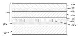
도 3은 반사형 LCOS SLM의 개략도이다.
도 4는, 실실예들에 따라, 장면 내의 재생 필드에서 홀로그래픽 재구성을 생성하는 SLM 및 장면 내의 재생 필드의 개별 시야(IFOV)의 어레이로부터의 광을 검출하도록 배열된 어레이 검출기를 포함하는 홀로그램 LIDAR 시스템을 도시하는 개략도이다.
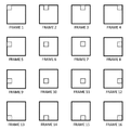
도 5a는, 일 실시예에 따라, 홀로그래픽 스캔의 각각의 제1 및 제2 프레임에 의해 형성된 제1 및 제2 광 풋프린트를 도시하며, 각각의 풋프린트는 장면 내의 재생 필드의 IFOV의 어레이를 조명하기 위한 서브 풋프린트 또는 "광점"의 패턴을 갖는 구조화된 광을 포함하고, 광점들의 형상이 프레임들 사이에서 변경된다;
도 5b는, 다른 실시예 따라, 홀로그래픽 스캔의 각각의 제1 및 제2 프레임에 의해 형성된 제1 및 제2 광 풋프린트를 도시하며, 각각의 풋프린트는 장면 내에서 재생 필드의 IFOV의 어레이의 IFOV의 서브 세트를 조명하기위한 광점 패턴을 갖는 구조화된 광을 포함하고, 여기서, 광점들의 패턴은 IFOV의 상이한 서브 세트를 조명하도록 프레임들 사이에서 변경된다;
도 5c는, 또 다른 실시예에 따라, 도 5b의 실시예와 동등한 제1 및 제2 광 풋프린트를 도시하며, 여기서 광점들의 형상이 프레임들 사이에서 추가로 변경된다;
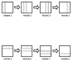
도 6은, 또 다른 실시예에 따라, 홀로그래픽 스캔의 프레임들의 시퀀스에 의해 형성된 광 풋프린트의 시퀀스를 도시하며, 각각의 풋프린트는 단일 서브-풋프린트(sub-footprint) 또는 "광점(light spot)"을 사용하여 장면 내 재생 필드의 IFOV 어레이의 IFOV를 개별적으로 스캐닝하기 위한 구조화된 광을 포함한다;
도 7은, 다른 실시예에 따라, 홀로그래픽 스캔의 프레임의 시퀀스에 의해 형성된 광 풋프린트의 시퀀스를 도시하며, 각각의 풋프린트는 1 차원 서브-풋프린트 또는 "라인"을 사용하여 장면 내에서 재생 필드의 IFOV를 개별적으로 스캐닝하기 위한 구조화된 광을 포함한다;
도 8은, 또 다른 실시예에 따라, 홀로그래픽 스캔의 대응하는 프레임들에 의해 형성된 n 번째 및 (n + 1)번 째 광 풋프린트를 도시하며, 각각의 풋프린트는 각각의 IFOV에 대한 상이한 서브 풋프린트를 사용하여 장면 내에서 재생 필드의 IFOV의 어레이를 조명하기 위한 구조화된 광을 포함한다;
도 9는, 다른 실시예에 따라, 홀로그래픽 스캔의 제1 내지 제5 프레임에 의해 형성된 제1 내지 제5 광 풋프린트를 도시하며, IFOV의 어레이 내의 열(column)에서 열에 대응하는 복수의 IFOV를 조명하기 위해 각각의 풋프린트가 라인의 복수의 광점을 갖는 구조화된 광을 포함하고, 여기서, 광점 라인이 프레임들 사이에서 재배치되는 된다;
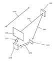
도 10은 홀로그램 프로젝터가 시야를 갖는 검출기의 공간 해상도를 효과적으로 증가시키기 위해 어떻게 사용될 수 있는지를 도시한다.
도 11은 광 검출기로부터 수신된 신호에 기초하여 복수의 컴퓨터 생성 홀로그램을 결정하기 위한 피드백 시스템을 도시한다.
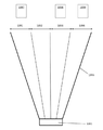
도 12는 각도 확대 시스템의 예를 도시 한 도면이고 ; 그리고
도 13은 실시예들에 따른 물체의 검출 및 범위 결정 방법을 도시한다.
도면에서, 동일한 참조 번호는 동일하거나 유사한 부분을 지칭한다.Specific embodiments are described by way of example only with reference to the following drawings:
1 is a schematic diagram showing a reflective SLM creating a holographic reconstruction on a screen.
2A shows the first iteration of the exemplary Gerchberg-Saxton type algorithm.
2B shows the second and subsequent iterations of the Gerchberg-Saxton type algorithm.
2C shows an alternative second and subsequent iteration of the Gerchberg-Saxton type algorithm.
3 is a schematic diagram of a reflective LCOS SLM.
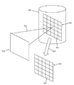
FIG. 4 is a hologram LIDAR comprising an array detector arranged to detect light from an array of individual fields of view (IFOV) and a SLM generating a holographic reconstruction in a playback field in a scene, according to practical examples. It is a schematic diagram showing the system.
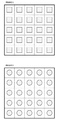
5A shows first and second optical footprints formed by respective first and second frames of a holographic scan, each footprint being an array of IFOVs of a reproduction field in a scene, according to one embodiment. Includes a structured light having a pattern of "light spots" or a sub-footprint for illuminating, and the shape of the light spots is changed between frames;
FIG. 5B shows first and second optical footprints formed by respective first and second frames of a holographic scan, each footprint being an array of IFOVs of a reproduction field within a scene. Includes a structured light having a light spot pattern for illuminating a subset of the IFOV, wherein the pattern of light spots is changed between frames to illuminate a different subset of the IFOV;
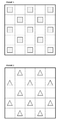
5C shows, according to another embodiment, first and second optical footprints equivalent to the embodiment of FIG. 5B, wherein the shape of the light spots is further altered between frames;
6 shows a sequence of light footprints formed by a sequence of frames of a holographic scan, according to another embodiment, each footprint being a single sub-footprint or "light. spot) ”to structured light for individually scanning the IFOV of the IFOV array of the playback field in the scene;
7 shows a sequence of optical footprints formed by a sequence of frames of a holographic scan, in accordance with another embodiment, each footprint within a scene using a one-dimensional sub-footprint or "line" Includes structured light for individually scanning the IFOV of the reproduction field;
FIG. 8 shows the nth and (n + 1) th optical footprints formed by corresponding frames of the holographic scan, each footprint being different for each IFOV. Includes structured light to illuminate the array of IFOVs of the reproduction field within the scene using the sub-footprint;
9 shows first to fifth optical footprints formed by the first to fifth frames of a holographic scan, according to another embodiment, a plurality of IFOVs corresponding to columns in a column in an array of IFOVs To illuminate, each footprint includes structured light having a plurality of light spots in the line, where the light spot lines are rearranged between frames;
10 shows how a hologram projector can be used to effectively increase the spatial resolution of a detector with a field of view.
11 shows a feedback system for determining a plurality of computer generated holograms based on signals received from a photo detector.
12 is a view showing an example of an angle enlargement system; And
13 illustrates a method of detecting and determining an object according to embodiments.
In the drawings, the same reference numbers refer to the same or similar parts.
본 발명은 다음에 설명되는 구성에 제한되지 않으며, 첨부된 청구 범위의 전체 범위로 확장된다. 즉, 본 발명은 다른 형태로 실시될 수 있으며 설명을 위하여 제시된 기술 내용의 구성에 한정되는 것으로 해석되어서는 안된다.The invention is not limited to the configurations described below, but extends to the full scope of the appended claims. That is, the present invention can be implemented in other forms and should not be construed as being limited to the construction of the technical content presented for explanation.
단수 형태의 용어는 달리 명시되지 않는 한 복수 형태를 포함 할 수 있다.Terms in the singular form may include plural forms unless otherwise specified.
다른 구조물의 상부/하부 또는 상/하에 형성된 구조물이라고 기술된 경우, 구조물들이 서로 접촉하는 경우 및 제3의 구조물이 그 사이에 배치되는 경우를 포함하는 것으로 해석되어야 한다.When described as a structure formed on top / bottom or top / bottom of another structure, it should be interpreted as including cases in which the structures are in contact with each other and a third structure is disposed between them.
시간 관계를 기술함에 있어서, 사건의 시간 순서가 예를 들어 "후", "후속", "다음", "전" 등으로 기술될 때, 본 개시는 별도로 규정하지 않는 한은 연속적 및 비연속적 사건을 포함하는 것으로 간주되어야 한다. 예를 들어, 그 기재가 "막(just)", "바로(immediate)" 또는 "직접(direct)"라는 기재가 사용되지 않는 한, 비연속적 경우를 포함하는 것으로 간주되어야 한다. In describing time relationships, when the time sequence of events is described as, for example, "after", "following", "next", "before", etc., the present disclosure is directed to continuous and discontinuous events unless otherwise specified. It should be considered inclusive. For example, the description should be considered to include non-consecutive cases unless a description such as “just”, “immediate” or “direct” is used.
"제1", "제2" 등의 용어는 다양한 요소를 설명하기 위해 본 명세서에서 사용될 수 있지만, 이러한 요소들은 이들 용어에 의해 제한되지 않는다. 이 용어는 하나의 요소를 다른 요소와 구별하기 위해서만 사용된다. 예를 들어, 제1요소는 제2요소로 지칭될 수 있고, 유사하게, 제2요소는 첨부된 청구 범위를 벗어남 없이 제1요소로 지칭될 수 있다. Terms such as “first”, “second”, and the like can be used herein to describe various elements, but these elements are not limited by these terms. This term is only used to distinguish one element from another. For example, the first element may be referred to as the second element, and similarly, the second element may be referred to as the first element without departing from the appended claims.
상이한 구성의 특징들은 부분적으로 또는 전체적으로 서로 연결되거나 결합될 수 있으며, 다양한 형태로 서로 상호 작용할 수 있다. 어떤 구성은 서로 독립적으로 수행될 수도 있고, 서로 연계되어 함께 수행될 수도 있다. 이하의 상세한 설명에서 상이한 실시예가 개별적으로 개시될 수 있지만, 임의의 실시예들의 임의의 특징들은 임의의 다른 특징들 또는 임의의 다른 실시예들의 특징의 조합과 결합될 수 있다. 즉, 본 개시에 기술된 특징들의 모든 가능한 조합물 및 치환물이 고려될 수 있다.The features of different configurations may be partially or wholly connected to or combined with each other, and may interact with each other in various forms. Some configurations may be performed independently of each other or may be performed together in connection with each other. Although different embodiments may be disclosed separately in the detailed description below, any features of any embodiments may be combined with any other features or combination of features of any other embodiments. That is, all possible combinations and substitutions of the features described in this disclosure are contemplated.
광학 구성Optical composition
도 1은 컴퓨터 생성 홀로그램이 단일 공간 광 변조기 상에 인코딩 되는 실시예를 도시한다. 컴퓨터 생성 홀로그램은 재구성을 위한 객체의 푸리에 변환이다. 따라서 홀로그램은 객체의 푸리에 도메인 또는 주파수 도메인 또는 스펙트럼 도메인 표현이라고 말할 수 있다. 일 실시예에서, 공간 광 변조기는 실리콘 장치, “” 상의 반사형 액정이다. 홀로그램은 공간 광 변조기 상에 인코딩 되고, 홀로그래픽 재구성은 재생 필드, 예컨대 스크린 또는 디퓨져와 같은 수광 부재 또는 스크린에 형성된다.1 shows an embodiment in which a computer generated hologram is encoded on a single spatial light modulator. A computer generated hologram is a Fourier transform of an object for reconstruction. Hence, the hologram can be said to be the Fourier domain or frequency domain or spectral domain representation of the object. In one embodiment, the spatial light modulator is a silicon device, a reflective liquid crystal on the “”. The hologram is encoded on a spatial light modulator, and the holographic reconstruction is formed in a reproduction field, such as a light receiving member or screen, such as a screen or diffuser.
예컨대 레이저나 레이저 다이오드 같은 광원(110)은 콜리메이팅 렌즈(Collimating Lens, 111)를 통해 SLM(140)에 조사하도록 배치된다. 콜리메이팅 렌즈는 광이 SLM 상에 전체적으로 평면 파면으로 입사되도록 만든다. 파면의 방향은(예컨대, 투명층의 평면 대비 완전 직각으로부터 2*또는 3*정도 떨어진) 약간 오프노멀(Off-Normal)하다. 다른 실시들예에서, 전체적으로 평면 파면은 예를 들어 빔 스플리터를 사용하여 수직 입사 방식으로 제공된다. 도 1에 도시된 예시에서, 이러한 배치는, 광원으로부터 오는 광이 SLM의 후방면의 미러에 반사되며 출사 파면(Exiting Wavefront, 112)을 형성하기 위해 위상-변조층(phase-modulating layer)과 상호작용하게 한다. 출사 파면(112)은 스크린(125)에 초점이 맞춰진 푸리에 변환 렌즈(120)를 포함하는 광학계에 적용된다. 보다 구체적으로, 푸리에 변환 렌즈(120)는 SLM(140)으로부터 변조 된 광 빔을 수신하고 스크린(125)에서 홀로그래픽 재구성을 생성하기 위해 주파수 공간 변환을 수행한다.For example, the
특히, 이러한 유형의 홀로그램에서 홀로그램의 각 픽셀들이 전체 재구성에 관여한다. 재생필드 상의 특정 지점들(또는 이미지 픽셀들)과 특정 광 변조 요소들(또는 홀로그램 픽셀들) 간에는 일대일 상관 관계가 없다. 즉, 광 변조층으로부터 출사되는 변조된 광은 재생필드에 걸쳐서 분배된다.In particular, in this type of hologram, each pixel of the hologram is involved in the overall reconstruction. There is no one-to-one correlation between certain points on the reproduction field (or image pixels) and certain light modulation elements (or hologram pixels). In other words, the modulated light emitted from the light modulating layer is distributed over the reproduction field.
이 실시예들에서, 공간 상에서의 홀로그래픽 재구성의 위치는 푸리에 변환 렌즈의 광 파워(optical power)에 의해 결정된다. 도 1에 도시된 실시예에서, 푸리에 변환 렌즈는 물리적 렌즈이다. 즉, 푸리에 변환 렌즈는 광학적 푸리에 변환 렌즈이며 푸리에 변환은 광학적으로 수행된다. 임의의 렌즈가 푸리에 변환 렌즈로 작동 할 수 있지만 렌즈의 성능은 푸리에 변환의 정확도를 제한할 것이다. 당업자라면 렌즈를 사용하여 광학 푸리에 변환을 수행하는 방법을 이해한다고 볼 것이다.In these embodiments, the location of the holographic reconstruction in space is determined by the optical power of the Fourier transform lens. In the embodiment shown in Figure 1, the Fourier transform lens is a physical lens. That is, the Fourier transform lens is an optical Fourier transform lens and the Fourier transform is performed optically. Any lens can function as a Fourier transform lens, but the performance of the lens will limit the accuracy of the Fourier transform. Those skilled in the art will appreciate understanding how to perform an optical Fourier transform using a lens.
홀로그램 계산Hologram calculation
일부 실시예에서, 컴퓨터 생성 홀로그램은 푸리에 변환 홀로그램, 또는 단순히 푸리에 홀로그램 또는 푸리에 기반 홀로그램이고, 여기서 이미지는 양의 렌즈의 푸리에 변환 특성을 이용하여 파-필드(far-field)에서 재구성된다. 푸리에 홀로그램은 재생면의 원하는 광 필드를 푸리에 변환하여 렌즈 평면에 오도록 계산된다. 컴퓨터 생성 푸리에 홀로그램은 푸리에 변환을 사용하여 계산될 수 있다.In some embodiments, the computer generated hologram is a Fourier transform hologram, or simply a Fourier hologram or a Fourier based hologram, where the image is reconstructed in the far-field using the Fourier transform property of the positive lens. The Fourier hologram is calculated to Fourier transform the desired light field of the reproduction surface to come to the lens plane. The computer generated Fourier hologram can be computed using Fourier transform.
푸리에 변환 홀로그램은 게르흐버그-섹스톤(Gerchberg-Saxton) 알고리즘과 같은 알고리즘을 사용하여 계산 될 수 있다. 또한, 게르흐버그-섹스톤 알고리즘은 공간 도메인 내 진폭-한정 정보(예컨대, 사진) 로부터 푸리에 도메인 내 홀로그램(예를 들어, 푸리에 변환 홀로그램)을 계산하는 데 사용될 수 있다. 즉, 객체에 관한 위상 정보는 공간영역 내의 진폭-한정 정보로부터 "얻어질(retrieved)" 수 있다. 몇몇 실시예들에서 컴퓨터 생성 홀로그램은 게르흐버그-섹스톤 알고리즘 또는 그 다양한 변환 응용법들을 이용해 진폭-한정 정보로부터 계산된다.The Fourier transform hologram can be calculated using an algorithm such as the Gerchberg-Saxton algorithm. In addition, the Gerchburg-Sexton algorithm can be used to calculate a hologram in a Fourier domain (eg, a Fourier transform hologram) from amplitude-limited information in a spatial domain (eg, photos). That is, the phase information about the object can be “retrieved” from the amplitude-limited information in the spatial domain. In some embodiments, the computer-generated hologram is calculated from amplitude-limited information using the Gerchburg-Sexton algorithm or various conversion applications thereof.
게르흐버그-색스톤 알고리즘은, 각각의 평면 A와 B에서 광빔(light beam) IA(x, y) 및 IB(x, y)의 강도 단면(intensity cross-sections)이 각각 단일 푸리에 변환으로 상호 연관되어 있는 상황을 고려한다. 주어진 강도 단면에서, 평면 A 및 B에서의 각각의 위상 분포에 대한 근사치인 ΨA(x, y) 및 ΨB(x, y) 가 구해진다. 게르흐버그-색스톤 알고리즘은 반복 프로세스(iterative process)를 따름으로써 이 문제에 대한 해결책을 찾는다. 게르흐버그-색스톤 알고리즘은 공간 영역과 푸리에(스펙트럼 또는 주파수) 영역 사이에서 IA(x, y) 및 IB(x, y)를 대표하는 데이터 세트(진폭 및 위상)를 반복적으로 전달하면서(repeatedly transferring) 공간적 및 스펙트럼 제약(constraints)을 반복적으로 적용한다. 공간 및 스펙트럼 제약 조건은 각각 IA(x, y) 및 lB(x, y)이다. 공간 또는 스펙트럼 영역의 제약 조건은 데이터 세트의 진폭에 부여된다. 해당 위상 정보는 일련의 반복을 통해 얻어진다.In the Gerchburg-Saxon algorithm, the intensity cross-sections of light beams I A (x, y) and I B (x, y) in each plane A and B, respectively, are transformed into a single Fourier. Consider the interrelated situations. For a given intensity section, approximate Ψ A (x, y) and Ψ B (x, y) for each phase distribution in planes A and B are obtained. The German-Saxon algorithm finds a solution to this problem by following an iterative process. The Gerburg-Saxon algorithm repeatedly passes data sets (amplitude and phase) representative of I A (x, y) and I B (x, y) between the spatial domain and the Fourier (spectrum or frequency) domain. (repeatedly transferring) Spatial and spectral constraints are applied repeatedly. The spatial and spectral constraints are I A (x, y) and l B (x, y), respectively. Constraints in the spatial or spectral domain are imposed on the amplitude of the data set. The corresponding phase information is obtained through a series of iterations.
몇몇 실시예들에서, 위상한정 홀로그램은 영국 특허 제2,498,170 호 또는 제2,501,112 호에 기술 된 바와 같은 게르흐버그-색스톤 알고리즘에 기반한 알고리즘을 사용하여 계산되며, 이는 전체로서 원용되어 본 명세서에 통합된다. 다만, 본 명세서에 기술된 위상 한정 홀로그램을 계산하는 것은 단지 예시로서 기술된 것에 불과하다. 이 실시예들에서, 게르흐버그-색스톤 알고리즘은 알려진 진폭 정보 T[x, y]를 나타내는 데이터 세트에 푸리에 변환의 위상 정보 Ψ[u, v]를 획득하고, 여기서, 진폭 정보 T[x, y]는 대상 이미지(예컨대, 사진)를 나타낸다. 크기 및 위상은 푸리에 변환에 의해 본질적으로 결합되기 때문에, 변환된 크기 및 위상은 계산된 데이터 세트의 정확도와 관련된 유용한 정보를 내포한다. 이에, 이 알고리즘은 진폭 및 위상 정보 모두를 피드백 하는 방식으로 반복적으로 사용될 수 있다. 그러나, 이 실시예들에서, 위상 정보 Ψ[u, v]만이 이미지 평면에서 대상 이미지를 표현하는 홀로그램을 형성하기 위해 홀로그램으로서 사용된다. 홀로그램은 위상 값들의 데이터 세트(예, 2D 어레이)이다.In some embodiments, the phase-limiting hologram is calculated using an algorithm based on the Gerburg-Saxon algorithm as described in British Patent Nos. 2,498,170 or 2,501,112, which is incorporated herein by reference in its entirety. . However, calculating the phase-limited hologram described in this specification is merely an example. In these embodiments, the Gerburg-Saxon algorithm obtains the phase information Ψ [u, v] of the Fourier transform in a data set representing known amplitude information T [x, y], where the amplitude information T [x , y] represents the target image (eg, photo). Since magnitude and phase are essentially combined by Fourier transform, the transformed magnitude and phase contains useful information related to the accuracy of the calculated data set. Thus, this algorithm can be used repeatedly by feeding back both amplitude and phase information. However, in these embodiments, only the phase information Ψ [u, v] is used as a hologram to form a hologram representing the target image in the image plane. The hologram is a data set of phase values (eg, 2D array).
다른 실시예들에서, 게르흐버그-섹스톤 알고리즘에 기반한 알고리즘이 완전 복소 홀로그램(fully-complex hologram)을 계산하기 위해 사용된다. 완전 복소 홀로그램은 크기 성분 및 위상 성분을 갖는 홀로그램이다. 홀로그램은 복소 데이터 값을 갖는 데이터 세트(예를 들어, 2D 어레이)이며, 여기서 각각의 복소 값은 크기 성분 및 위상 성분을 가진다.In other embodiments, an algorithm based on the Gerburg-Sexton algorithm is used to calculate a fully-complex hologram. A fully complex hologram is a hologram having a magnitude component and a phase component. A hologram is a data set (eg, 2D array) with complex data values, where each complex value has a magnitude component and a phase component.
몇몇 실시예들에서, 이 알고리즘은 복소 데이터를 처리하고 푸리에 변환은 복소 푸리에 변환이다. 복소 데이터는(i) 실수 성분 및 허수 성분 또는(ii) 크기 성분 및 위상 성분을 포함하는 것으로 간주 될 수 있다. 몇몇 실시예들에서, 복소수 데이터의 2 개의 성분은 알고리즘의 여러 단계들에서 상이하게 처리된다.In some embodiments, this algorithm processes complex data and the Fourier transform is a complex Fourier transform. Complex data can be considered to include (i) real and imaginary components or (ii) magnitude and phase components. In some embodiments, two components of complex data are processed differently at various stages of the algorithm.
도 2a는 위상-한정 홀로그램을 계산하기 위한 일부 실시예에 따른 알고리즘의 제1반복을 도시한다. 알고리즘에 대한 입력은 화소 또는 데이터 값의 2D 어레이를 포함하는 입력 이미지(210)이며, 여기서 각 화소 또는 데이터 값은 크기 또는 진폭 값이다. 즉, 입력 이미지(210)의 각 화소 또는 데이터 값은 위상 성분을 갖지 않는다. 따라서, 입력 이미지(210)는 크기-한정 또는 진폭-한정 또는 세기-한정 분포로 간주될 수 있다. 이러한 입력 이미지(210)의 일례는 프레임의 시간적 시퀀스를 포함하는 비디오 또는 사진의 한 프레임이다. 알고리즘의 제1반복은 랜덤 위상 분포(또는 랜덤 위상 시드)(230)를 사용하여, 초기 복소 데이터 세트(starting complex data set)의 각각의 데이터 요소가 크기 및 위상을 포함하도록, 입력 이미지의 각 화소에 랜덤 위상 값을 할당하는 단계를 포함하는 데이터 형성 단계(202A)에서 시작한다. 초기 복소 데이터 세트는 공간 도메인에서의 입력 이미지를 나타낸다고 말할 수 있다.2A shows a first iteration of an algorithm according to some embodiments for computing a phase-limited hologram. The input to the algorithm is an
제1프로세싱 블록(250)은 초기 복소 데이터 세트를 수신하고 복소 푸리에 변환을 수행하여 푸리에 변환된 복소 데이터 세트를 형성한다. 제2프로세싱 블록(253)은 푸리에 변환된 복소 데이터 세트를 수신하여 홀로그램(280A)을 출력한다. 일부 실시예에서, 홀로그램(280A)은 위상-한정 홀로그램이다. 이들 실시예에서, 제2프로세싱 블록(253)은 각각의 위상 값을 양자화하고 홀로그램(280A)을 형성하기 위해 각 진폭 값을 1로 설정한다. 각 위상 값은 위상-한정 홀로그램을 "표시"하는데 사용될 공간 광 변조기의 화소 상에 표현될 수 있는 위상 레벨에 따라 양자화된다. 예를 들어, 공간 광 변조기의 각 화소가 256 개의 상이한 위상 레벨을 제공하면, 홀로그램의 각 위상 값은 256개의 가능한 위상 레벨 중 하나의 위상 레벨로 양자화된다. 홀로그램(280A)은 입력 이미지를 나타내는 위상-한정 푸리에 홀로그램이다. 다른 실시예에서, 홀로그램(280A)은 수신된 푸리에 변환된 복소 데이터 세트로부터 유도된 복소 데이터 값(각각 진폭 성분 및 위상 성분을 포함함)의 어레이를 포함하는 완전-복소 홀로그램이다. 일부 실시예에서, 제2프로세싱 블록(253)은 홀로그램(280A)을 형성하기 위해 복수의 허용 가능한 복소 변조 레벨 중 하나로 각각의 복소 데이터 값을 제한한다. 제한 단계는 복소수 평면에서 각 복소 데이터 값을 가장 가까운 허용 복소수 변조 레벨로 설정하는 단계를 포함할 수 있다. 홀로그램(280A)은 스펙트럼 또는 푸리에 또는 주파수 도메인에서의 입력 이미지를 나타낸다고 말할 수 있다. 일부 실시예에서, 알고리즘은 이 시점에서 정지한다.The
그러나, 다른 실시예에서, 알고리즘은 도 2A의 점선 화살표로 나타낸 바와 같이 계속된다. 즉, 도 2A의 점선 화살표를 따르는 단계는 선택적이다(즉, 모든 실시예에 필수적인 것은 아님).However, in other embodiments, the algorithm continues as indicated by the dashed arrows in FIG. 2A. That is, the step following the dashed arrows in FIG. 2A is optional (ie, not required for all embodiments).
제3프로세싱 블록(256)은 제2프로세싱 블록(253)으로부터 수정된 복소 데이터 세트를 수신하고, 역 푸리에 변환된 복소 데이터 세트를 형성하기 위해 역 푸리에 변환을 수행한다. 역 푸리에 변환된 복소 데이터 세트는 공간 도메인에서의 입력 이미지를 나타낸다고 말할 수 있다.The
제4프로세싱 블록(259)은 역 푸리에 변환된 복소 데이터 세트를 수신하고, 진폭 값(211A)의 분포 및 위상 값(213A)의 분포를 추출한다. 선택적으로, 제4프로세싱 블록(259)은 진폭 값들(211A)의 분포를 평가한다. 구체적으로, 제4프로세싱 블록(259)은 역 푸리에 변환된 복소 데이터 세트의 진폭 값(211A)의 분포를, 당연히 진폭 값의 분포인, 입력 이미지(510)와 비교할 수 있다. 진폭 값들(211A)과 입력 이미지(210)의 분포 사이의 차이가 충분히 작으면, 제4프로세싱 블록(259)은 홀로그램(280A)이 허용 가능한 것으로 결정할 수 있다. 즉, 진폭 값들(211A)의 분포와 입력 이미지(210)의 차이가 충분히 작으면, 제4프로세싱 블록(259)은 홀로그램(280A)이 입력 이미지(210)를 충분히 정확하게 나타내는 것으로 결정할 수 있다. 일부 실시예들에서, 비교 과정에서 역 푸리에 변환된 복소 데이터 세트의 위상 값(213A)의 분포는 무시된다. 진폭 값들(211A) 및 입력 이미지(210)의 분포를 비교하기위한 임의의 수의 상이한 방법들이 이용될 수 있으며, 본 개시는 임의의 특정 방법에 제한되지 않음을 이해할 것이다. 일부 실시예들에서, 평균 제곱 차이가 계산되고, 평균 제곱 차이가 임계 값 보다 작은 경우, 홀로그램(280A)은 수용 가능한 것으로 간주된다. 제4프로세싱 블록(259)이 홀로그램(280A)이 수용 가능하지 않다고 결정하면, 알고리즘의 추가 반복이 수행될 수 있다. 그러나, 이러한 비교 단계는 필수적인 것은 아니며, 다른 실시예에서, 수행된 알고리즘의 반복 횟수는 미리 결정되거나 미리 설정되거나 사용자 정의된다.The fourth processing block 259 receives the inverse Fourier transformed complex data set, and extracts the distribution of the amplitude value 211A and the distribution of the phase value 213A. Optionally, fourth processing block 259 evaluates the distribution of amplitude values 211A. Specifically, the fourth processing block 259 can compare the distribution of the amplitude values 211A of the inverse Fourier transformed complex data set with the input image 510, which is, of course, the distribution of the amplitude values. If the difference between the amplitude values 211A and the distribution of the
도 2b는 알고리즘의 두 번째 반복 및 알고리즘의 임의의 반복을 나타낸다. 선행 반복의 위상 값(213A)의 분포는 알고리즘의 처리 블록을 통해 피드백 된다. 제1반복에서, 데이터 형성 단계(202A)는 입력 이미지(210)의 진폭 값들의 분포를 랜덤 위상 분포(230)와 결합하여 제1복소 데이터 세트를 형성한다. 그러나, 두 번째 및 후속 반복에서, 데이터 형성 단계(202B)는(i) 알고리즘의 이전 반복으로부터의 위상 값(213A)의 분포와(ii) 입력 이미지(210)의 진폭 값들의 분포를 합하여 복소 데이터 세트를 형성하는 단계를 포함한다. 2B shows the second iteration of the algorithm and any iteration of the algorithm. The distribution of the phase value 213A of the preceding iteration is fed back through the processing block of the algorithm. In the first iteration, the data forming step 202A combines the distribution of the amplitude values of the
도 2b의 데이터 형성 단계(202B)에 의해 형성된 복소 데이터 세트는 도 2a를 참조하여 기술된 것과 동일한 방식으로 처리되어 제2반복 홀로그램(280B)을 형성한다. 따라서 여기에서 프로세스의 설명은 반복되지 않는다. 알고리즘은 제2반복 홀로그램(280B)이 계산되면 중단될 수 있다. 그러나, 알고리즘의 임의의 수의 추가 반복이 수행될 수 있다. 제3프로세싱 블록(256)은 제4프로세싱 블록(259)이 요구되거나 더 많은 반복이 요구되는 경우에만 요구된다는 것을 이해할 것이다. 출력 홀로그램(280B)은 일반적으로 반복마다 개선된다. 그러나 실제로는, 측정 가능한 개선이 관찰되지 않거나, 처리 시간의 증가라는 부정적 효과가 추가 반복을 수행하는 긍정적 이점 보다 커지는 시점이 도달한다. 따라서, 알고리즘은 반복적이고 수렴적으로 기술된다.The complex data set formed by the data forming step 202B in FIG. 2B is processed in the same manner as described with reference to FIG. 2A to form the second repeating hologram 280B. Therefore, the description of the process is not repeated here. The algorithm can be stopped when the second iteration hologram 280B is calculated. However, any number of additional iterations of the algorithm can be performed. It will be understood that the
도 2c는 두 번째 및 후속 반복의 대안적인 실시예를 나타낸다. 선행 반복의 위상 값(213A)의 분포는 알고리즘의 프로세싱 블록을 통해 피드백 된다. 진폭 값(211A)의 분포는 대안적인 진폭 값의 분포를 위해 소거된다. 이 대안적인 실시예에서, 대안적인 진폭 값의 분포는 이전 반복의 진폭 값(211)의 분포로부터 도출된다. 특히, 프로세싱 블록(258)은 이전 반복의 진폭 값들(211)의 분포로부터 입력 이미지(210)의 진폭 값들의 분포를 감산하고, 그 차이를 이득 계수 α만큼 스케일링하고, 입력 이미지(210)로부터 스케일링 된 차분을 감산한다. 이는 다음의 방정식에 의해 수학적으로 표현되며, 아래 첨자 텍스트 및 숫자는 반복 횟수를 나타낸다.2C shows an alternative embodiment of the second and subsequent iterations. The distribution of the phase value 213A of the preceding iteration is fed back through the processing block of the algorithm. The distribution of amplitude values 211A is canceled for an alternative distribution of amplitude values. In this alternative embodiment, the distribution of alternative amplitude values is derived from the distribution of

여기서:here:
F'는 역 푸리에 변환이고;F 'is the inverse Fourier transform;
F는 순방향 푸리에 변환이고;F is the forward Fourier transform;
R[x, y]는 제3프로세싱 블록(256)에 의해 출력된 복소 데이터 세트이고;R [x, y] is the complex data set output by the
T[x, y]는 입력 또는 대상 이미지이고;T [x, y] is the input or target image;
∠는 위상 성분이고;∠ is the phase component;
ψ는 위상-한정 홀로그램(280B)이고;ψ is phase-limited hologram 280B;
η은 진폭 값(211B)의 새로운 분포이며;η is the new distribution of amplitude values 211B;
α는 이득 계수이다.α is the gain factor.
이득 계수 α는 고정되거나 가변적일 수 있다. 일부 실시예에서, 이득 계수 α는 입력 목표 이미지 데이터의 크기 및 속도(rate)에 기초하여 결정된다. 일부 실시예에서, 이득 계수 α는 반복 횟수에 의존한다. 일부 실시예에서, 이득 계수 α는 단지 반복 횟수의 함수이다.The gain factor α can be fixed or variable. In some embodiments, the gain factor α is determined based on the size and rate of the input target image data. In some embodiments, the gain factor α depends on the number of iterations. In some embodiments, the gain factor α is only a function of the number of iterations.
도 2c의 실시예는 다른 모든 면에서 도 2a 및 도 2b의 실시예와 동일하다. 위상-한정 홀로그램 ψ(u, v)는 주파수 또는 푸리에 도메인에서의 위상 분포를 포함한다고 말할 수 있다.The embodiment of Figure 2c is identical to the embodiment of Figures 2a and 2b in all other respects. It can be said that the phase-limited hologram ψ (u, v) includes the phase distribution in the frequency or Fourier domain.
일부 실시예들에서, 푸리에 변환은 홀로그램 데이터 내 렌즈 데이터(lensing data)를 포함함으로써 컴퓨터로 수행된다. 즉, 홀로그램은 객체를 나타내는 데이터뿐만 아니라 렌즈를 나타내는 데이터를 포함한다. 이러한 실시예에서, 도 1의 물리적 푸리에 변환 렌즈(120)는 생략된다. 컴퓨터 생성 홀로그램 분야에서 렌즈를 나타내는 데이터를 계산하는 방법은 알려져 있다. 렌즈를 나타내는 데이터는 소프트웨어 렌즈로 지칭될 수 있다. 예를 들어, 위상-한정 홀로그래픽 렌즈는 그 굴절률 및 공간적으로 변하는 광 경로 길이로 인해 렌즈의 각각의 포인트에 의해 야기되는 위상 지연을 계산함으로써 형성될 수 있다. 예를 들어, 볼록 렌즈 중심에서의 광 경로 길이는 렌즈 가장자리에서의 광 경로 길이보다 길다. 진폭-한정 홀로그래픽 렌즈는 프레넬 존 플레이트(Fresnel zone plate)에 의해 형성될 수 있다. 또한, 컴퓨터 생성 홀로그램의 기술 분야에서, 렌즈를 나타내는 데이터를 홀로그램과 결합함으로써 그 홀로그램의 푸리에 변환이 물리적 푸리에 렌즈의 필요없이 수행될 수 있는 방법이 알려져 있다. 일부 실시예에서, 렌즈 데이터는 간단한 벡터 합산과 같은 단순 합산에 의해 홀로그래픽 데이터와 결합된다. 일부 실시예에서, 푸리에 변환을 수행하기 위해 소프트웨어 렌즈와 함께 물리적 렌즈가 사용된다. 대안적으로, 다른 실시예들에서, 홀로그래픽 재구성이 파-필드(far-field)에서 발생하도록 푸리에 변환 렌즈는 모두 생략된다. 다른 실시예에서, 홀로그램은 그레이팅(grating) 데이터, 즉 빔 스티어링(beam steering)과 같은 그레이팅의 기능을 수행하도록 형성된 데이터를 포함할 수 있다. 다시, 컴퓨터 생성 홀로그래피의 분야에서 그러한 홀로그래픽 데이터를 계산하고 이것을 객체를 나타내는 홀로그래픽 데이터와 결합시키는 방법은 알려져 있다. 예를 들어, 위상-한정 홀로그래픽 그레이팅은 블레이즈된(brazed) 그레이팅의 표면 상의 각 포인트에 의해 야기된 위상 지연을 모델링함으로써 형성될 수 있다. 진폭-한정 그레이팅은 객체를 나타내는 진폭-한정 홀로그램에 간단히 중첩(superimposed)되어 진폭-한정 홀로그램의 각도 스티어링(angular steering)을 제공할 수 있다.In some embodiments, the Fourier transform is performed by a computer by including lens data in hologram data. That is, the hologram includes data representing the lens as well as data representing the object. In this embodiment, the physical
일부 실시예에서, 푸리에 변환은 물리적 푸리에 변환 렌즈 및 소프트웨어 렌즈에 의해 공동으로 수행된다. 즉, 푸리에 변환에 기여하는 일부 광 파워는 소프트웨어 렌즈에 의해 제공되고, 푸리에 변환에 기여하는 나머지 광 파워는 물리적 광학 또는 광학들에 의해 제공된다.In some embodiments, the Fourier transform is performed jointly by a physical Fourier transform lens and a software lens. That is, some optical power contributing to the Fourier transform is provided by a software lens, and the remaining optical power contributing to the Fourier transform is provided by physical optics or optics.
일부 실시예에서, 이미지 데이터를 수신하고 알고리즘을 사용하여 실시간으로 홀로그램을 계산하도록 구성된 실시간 엔진이 제공된다. 일부 실시예에서, 이미지 데이터는 일련의 이미지 프레임을 포함하는 비디오이다. 다른 실시예에서, 홀로그램은 사전 계산되고, 컴퓨터 메모리에 저장되며, SLM 상에 디스플레이하기 위해 필요에 따라 호출된다. 즉, 일부 실시예에서, 소정의 홀로그램의 저장소가 제공된다.In some embodiments, a real-time engine configured to receive image data and compute a hologram in real time using an algorithm is provided. In some embodiments, the image data is video comprising a series of image frames. In another embodiment, the hologram is pre-computed, stored in computer memory, and invoked as needed to display on the SLM. That is, in some embodiments, a reservoir of a predetermined hologram is provided.
실시예는 푸리에 홀로그래피 및 게르흐버그-색스톤 타입 알고리즘에 관한 것이다. 본 개시는 포인트 클라우드 방법에 기초한 것과 같은 다른 기술에 의해 계산된 프레넬 홀로그래피 및 홀로그램에도 동등하게 적용 가능하다.Embodiments relate to Fourier holography and Gerburg-Saxon type algorithms. The present disclosure is equally applicable to Fresnel holography and hologram calculated by other techniques such as based on the point cloud method.
광 변조Light modulation
공간 광 변조기는 컴퓨터 생성 홀로그램을 디스플레이 하는 데 사용될 수 있다. 홀로그램이 위상-한정 홀로그램인 경우, 위상을 변조하는 공간 광 변조기가 필요하다. 홀로그램이 완전-복소 홀로그램인 경우, 위상 및 진폭을 변조하는 공간 광 변조기가 사용될 수 있거나 위상을 변조하는 제1공간 광 변조기 및 진폭을 변조하는 제2공간 광 변조기가 사용될 수 있다.The spatial light modulator can be used to display a computer generated hologram. If the hologram is a phase-limited hologram, a spatial light modulator that modulates the phase is needed. When the hologram is a full-complex hologram, a spatial light modulator that modulates phase and amplitude can be used, or a first spatial light modulator that modulates phase and a second spatial light modulator that modulates amplitude can be used.
일부 실시예에서, 공간 광 변조기의 광 변조 소자(즉, 화소)는 액정을 포함하는 셀이다. 즉, 일부 실시예에서, 공간 광 변조기는 광학 능동 소자가 액정인 액정 장치이다. 각각의 액정 셀은 복수의 광 변조 레벨을 선택적으로 제공하도록 구성된다. 즉, 각 액정 셀은 어느 한 시점에서 복수의 가능한 광 변조 레벨들로부터 선택된 하나의 광 변조 레벨에서 동작하도록 구성된다. 각각의 액정 셀은 복수의 광 변조 레벨 중에서 다른 광 변조 레벨로 동적으로 재구성 가능하다. 일부 실시예에서, 공간 광 변조기는 실리콘(LCOS) 공간 광 변조기 상의 반사형 액정이지만, 본 발명은 이러한 유형의 공간 광 변조기에 한정하지 않는다.In some embodiments, the light modulation element (ie, pixel) of the spatial light modulator is a cell containing liquid crystal. That is, in some embodiments, the spatial light modulator is a liquid crystal device in which the optically active element is a liquid crystal. Each liquid crystal cell is configured to selectively provide a plurality of light modulation levels. That is, each liquid crystal cell is configured to operate at one light modulation level selected from a plurality of possible light modulation levels at any one time. Each liquid crystal cell is dynamically reconfigurable to a different light modulation level among a plurality of light modulation levels. In some embodiments, the spatial light modulator is a reflective liquid crystal on a silicon (LCOS) spatial light modulator, but the present invention is not limited to this type of spatial light modulator.
LCOS 장치는 작은 개구(예를 들어, 폭이 수 센티미터) 내의 조밀한 어레이의 광 변조 소자 또는 화소를 제공한다. 화소는 통상 약 10미크론 이하이어서 수 도 수준의 회절각을 가지며, 이는 광학 시스템이 콤팩트 할 수 있다는 것을 의미한다. LCOS SLM의 작은 개구를 적절하게 조광하는 것은 다른 액정 장치의 큰 개구를 조광하는 것보다 용이하다. LCOS 장치는 통상 반사형이므로 LCOS SLM의 화소를 구동하는 회로를 반사 표면 아래에 묻을 수 있다. 결과적으로 개구율이 높아진다. 즉, 화소는 밀집되어 있어 화소 간에 낭비되는 공간(dead space)이 거의 없음을 의미한다. 이는 재생 필드에서의 광학 노이즈를 감소시키므로 유리하다. LCOS SLM은 화소가 광학적으로 편평하다는 이점을 갖는 실리콘 후면을 사용한다. 이 점은 위상 변조 장치에서 특히 중요하다. LCOS devices provide a dense array of light modulating elements or pixels within a small aperture (eg, several centimeters in width). The pixels are usually about 10 microns or less, which has a diffraction angle of the order of a few degrees, which means that the optical system can be compact. Properly dimming the small openings of the LCOS SLM is easier than dimming the large openings of other liquid crystal devices. Since the LCOS device is usually reflective, the circuit driving the pixels of the LCOS SLM can be buried under the reflective surface. As a result, the aperture ratio increases. That is, the pixels are dense, meaning that there is almost no dead space between pixels. This is advantageous because it reduces the optical noise in the reproduction field. LCOS SLM uses a silicon back side that has the advantage that the pixels are optically flat. This is especially important for phase modulating devices.
단지 예시로서, 적합한 LCOS SLM이 도 3을 참조하여 아래와 같이 기술된다. LCOS 소자는 단결정 실리콘 기판(302)을 사용하여 형성된다. 이는 간극(301a)에 의해 이격되며 기판의 상부 표면에 배치된 사각 평면형 알루미늄 전극(301)의 2차원 어레이를 가진다. 전극(301) 각각은 기판(302)에 매설된 회로(302a)를 통해 형성될 수 있다. 각각의 전극들은 각각의 평면 미러를 형성한다. 배향층(Alignment Layer, 303)이 전극 어레이 상에 배치되고, 액정층(304)은 배향층(303)에 배치된다. 제2배향층(305)은 액정층(304)에 배치되고, 예컨대, 유리로 된 평면 투명층(306)은 제2배향층(305)에 배치된다. 예컨대 ITO로 된 단일 투명 전극(307)은 투명층(306)과 제2배향층(305) 사이에 배치된다.By way of example only, a suitable LCOS SLM is described below with reference to FIG. 3. The LCOS device is formed using a single
전극(301) 각각은, 투명전극(307) 영역 상부와 중간에 개재되는 액정물질과 함께, 종종 화소로 지칭되는 제어 가능한 위상 변조 소자(308)를 형성한다. 유효 화소 영역, 즉 충전율은 화소(301a) 사이의 공간까지 고려하여 광학적으로 활성인 총 화소의 비율이다. 각각의 전극(301)에 인가된 투명전극(307)에 대한 전압을 제어함으로써, 위상 변조된 요소의 액정 물질의 특성은 변화될 수 있고, 따라서 그에 입사되는 입사광에 가변 지연을 제공한다. 이렇게 함으로써 파면(wavefront)에 위상-한정 변조가 가해지는 한편 어떤 진폭 효과도 발생하지 않는다.Each of the
전술한 LCOS SLM는 공간적으로 변조된 광을 반사에 의해 출력한다. 반사형 LCOS SLM은 신호 라인, 게이트 라인 및 트랜지스터가 거울 면 아래에 있으며, 높은 충전율(일반적으로 90 % 이상) 및 고해상도를 얻을 수 있는 이점이 있다. 반사형 LCOS 공간 광 변조기를 사용하는 또 다른 이점은 투과형 장치가 사용되는 경우에 필요한 것보다 요구되는 액정 층 두께가 절반일 수 있다는 것이다. 이것은 액정의 스위칭 속도를 크게 향상시킨다(움직이는 비디오 이미지의 투영을 위한 주요 이점). 그러나, 본 발명의 개시 내용은 투과형 LCOS SLM을 사용하여 동일하게 구현될 수 있다.The aforementioned LCOS SLM outputs spatially modulated light by reflection. Reflective LCOS SLMs have the advantage that the signal lines, gate lines and transistors are under the mirror surface and high charge rates (typically over 90%) and high resolution are achieved. Another advantage of using a reflective LCOS spatial light modulator is that the required liquid crystal layer thickness can be half that required than if a transmissive device is used. This greatly improves the switching speed of the liquid crystal (the main advantage for the projection of moving video images). However, the disclosure of the present invention can be implemented the same using a transmissive LCOS SLM.
광 검출 및 거리 측정(“LiDAR”또는“LIDAR”) 시스템Optical detection and distance measurement (“LiDAR” or “LIDAR”) system
본 발명자는 본 발명의 홀로그래픽 기술을 사용하여 개선된 이미지 프로젝션을 제공하기 위한 다양한 방법들을 이전에 개시한 바 있다. 본 발명자는 이러한 홀로그래픽 기술이 또한 개선된 LIDAR 시스템의 근간을 이루는 것에 사용될 수 있다는 것을 인지 하였다. 구체적으로, 본 발명자는 이러한 기술이 LIDAR에대해 장면(scene)에 걸쳐 홀로그래픽으로 형성된 광 풋프린트를 스캔하는데 사용될 수 있음을 인식하였다. 예를 들어, 본 발명자의 초기 특허 출원 GB 2,560,491은 스캐닝 가능한 LIDAR 시스템을 개시하며, 여기서, 회전 프리즘과 같은 물리적 광학계 대신에 가변 격자 기능(variable grating function)에, 장면에 걸쳐 광 풋프린트의 연속 스캐닝을 수행하기 위해, 재생 필드(이는 광 풋프린트가 있는 영역을 정의함)를 이동시키는 것이 제공된다.The inventors have previously disclosed various methods for providing improved image projection using the holographic technology of the present invention. The inventors have recognized that this holographic technique can also be used to form the basis of an improved LIDAR system. Specifically, the inventors have recognized that this technique can be used for scanning optical footprints formed holographically across scenes for LIDAR. For example, the inventor's initial patent application GB 2,560,491 discloses a scannable LIDAR system, where a variable grating function instead of a physical optical system such as a rotating prism, continuous scanning of the optical footprint across the scene. To do this, it is provided to move the playback field (which defines the area where the optical footprint is located).
본 명세서에 개시된 추가적인 개선 사항에 따르면, 장면 내에서의 광 풋프린트의 위치 및 그 형태, 형상 및/또는 패턴과 같은 광 풋프린트의 다른 파라미터들은 컴퓨터 생성 홀로그램을 변경함으로써 변경될 수 있다. 홀로그램 프로젝션 분야의 당업자는 홀로그램을 변경하는 것과 디스플레이하기 전에 홀로그램에 수학적으로 추가되는 단순 격자 함수(simple grating function)를 변경하는 것의 차이를 이해할 것이다. 홀로그래픽 프로젝션 분야의 당업자는 또한 재생 필드의 광량을 변경하는 것과(홀로그래픽) 재생 필드를 재생 평면 주위에서 이동시키는 것의 차이를 이해할 것이다. 일부 실시예에서, 컴퓨터 생성 홀로그램에 대한 변경은 실시간 LIDAR 시스템의 개선을 용이하게 하기 위해 실시간으로 이루어진다.According to further improvements disclosed herein, other parameters of the optical footprint, such as the position, shape, shape and / or pattern of the optical footprint within the scene can be changed by changing the computer generated hologram. Those skilled in the art of hologram projection will appreciate the difference between changing the hologram and changing the simple grating function that is mathematically added to the hologram before being displayed. Those skilled in the art of holographic projection will also understand the difference between changing the amount of light in the reproduction field (holographic) and moving the reproduction field around the reproduction plane. In some embodiments, changes to the computer generated hologram are made in real time to facilitate improvement of the real time LIDAR system.
실시예들에서, 홀로그래픽 프로젝터는 공간 해상도를 갖는 광 검출기와 결합된다. 실시예들에서, 홀로그램 프로젝터는 광 검출기의 공간 해상도에 일치되는(또는 조정되는) 공간 해상도를 갖는 복수의 광점들(예를 들어, 어레이 또는 패턴)을 투사하는데 사용된다. 이러한 광 검출기가, 장면 내의 복수의 지점들과 동시에 그러한 광점들을 검사하기 위하여, 어떻게 광원 및 공간 광 변조기에 동기화될 수 있는 지는 이해될 수 있다. 보다 구체적으로, 적절한 동기화에 의해, 복수의 전달시간 측정(time-of-flight measurements) 측정이 동시에 이루어질 수 있다고 이해될 것이다. 광은 제1 특성 또는 속성을 가지며, 이는 검출기에 의해 수신된 다른 광과 구별될 수 있음을 의미한다. 광은 펄스화되고 홀로그램 시퀀스와 시간적으로 동기화될 수 있다. 실시예에서, 제1 특성 또는 속성은 제1 주파수에서의 진폭 변조이다. 그러나, 광은 임의의 다른 방식으로 특징지어질 수 있다. 실시예들에서, 제1 주파수는 무선 주파수(radio frequency)이다.In embodiments, the holographic projector is combined with a photo detector with spatial resolution. In embodiments, a hologram projector is used to project a plurality of light spots (eg, arrays or patterns) having a spatial resolution matched (or adjusted) to the spatial resolution of the photo detector. It can be understood how such a light detector can be synchronized to a light source and a spatial light modulator to check such light spots simultaneously with multiple points in the scene. More specifically, it will be understood that with proper synchronization, multiple time-of-flight measurements can be made simultaneously. The light has a first characteristic or property, which means it can be distinguished from other light received by the detector. The light can be pulsed and synchronized in time with the hologram sequence. In an embodiment, the first characteristic or property is amplitude modulation at a first frequency. However, the light can be characterized in any other way. In embodiments, the first frequency is a radio frequency.
본 발명자는, 장면 내 재생 필드의 개별 서브 영역과 일대일 상관 관계를 갖도록 배열된 광 검출 소자들의 어레이를 포함하는 광 검출기를 사용함으로써, "구조화된 광(structured light)" -다수의 광 특징들을 포함하는 광의 패턴-을 형성하는 컴퓨터 생성 홀로그램(이는 재생 필드 내의 상이한 영역들을 동시에 조명할 수 있음)을 사용할 수 있다는 것을 인식하였다. 따라서, 재생 필드의 다수의 서브 영역들은, 측량 효율을 향상시키기 위해, 홀로그램에 의해 형성된 광 풋프린트의 대응하는 광 특징들(예를 들어, 광점들) 또는 "서브 풋프린트"에 의해 동시에 측량(surveyed) 또는 검사(probed)될 수 있다. 또한, 본 발명자는 동일한 재생 필드 내에 있는 연속적인 컴퓨터 생성 홀로그램에 의해 형성된 광 특징들 또는 서브 풋프린트들의 형태, 형상, 크기, 배향 및 / 또는 패턴을 변경함으로써, 재생 필드 영역에 대한 보다 상세한 정보를 도출할 수 있음을 인식 하였다. The inventor includes a "structured light"-a number of optical features, by using a photo detector comprising an array of photodetecting elements arranged to have a one-to-one correlation with individual sub-regions of the reproduction field in the scene. It was recognized that a computer-generated hologram (which can simultaneously illuminate different areas in a reproduction field) that forms a pattern of light to be used. Thus, multiple sub-regions of the reproduction field are simultaneously surveyed by the corresponding light features (eg, light spots) or "sub-footprint" of the light footprint formed by the hologram to improve survey efficiency. It can be surveyed or probed. In addition, the present inventors can obtain more detailed information about the reproduction field area by changing the shape, shape, size, orientation and / or pattern of light features or sub-footprints formed by successive computer generated holograms within the same reproduction field. It was recognized that it could be derived.
이전에 제안된 홀로그램 "스캐닝 LIDAR"시스템에서, 단일 광 검출기는 전형적으로 광 풋프린트로부터의 광 리턴 신호를 검출하는데 사용된다. 광 풋프린트는 일정하게 유지되며(예 : 모양, 크기 및 형태) 전형적으로 해당 영역에서 균일한 밝기를 가진다. 광 풋프린트의 위치는 "빔 조향(beam steering)"에 의해 변경되고(예 : 격자 함수(graring fuction)을 사용함) 이로써 SLM에 표시된 홀로그램을 순차적으로 그리고 시간적으로 변경함으로써 장면의 다른 영역들을 조명한다. 본 발명에 따라 후술할 실시예들에서, 어레이 검출기가 사용된다. 어레이 검출기는 공간 분해능을 갖는 검출기이다. 어레이 검출기를 사용하면 동시에 여러 개의 광 리턴 신호를 감지할 수 있다. 보다 복잡한 광 풋프린트, 예를 들어 복수의 광점 또는 "서브 풋프린트"를 포함하는 광 패턴은 장면 내 복수의 지점들을 동시에 조명하기 위해 사용될 수 있다. 광 풋프린트는 "구조화된 광"을 포함하는 것으로 볼 수 있다. 후술할 실시예들에서, 광 풋프린트/구조화된 광은 SLM 상에 표시된 홀로그램을 순차적으로 그리고 시간적으로 변경함으로써 변경된다. 중요한 것은, 홀로그래픽 "스캐닝 LIDAR" 시스템과 달리, SLM 상에 표시된 2 개 이상의 홀로그램 시퀀스는 동일한 재생 필드 내에 광 풋프린트 / 구조화된 광을 형성하는데(즉, "빔 스티어링"없이) 사용된다.In the previously proposed hologram "scanning LIDAR" system, a single light detector is typically used to detect the light return signal from the light footprint. The optical footprint remains constant (eg, shape, size and shape) and typically has a uniform brightness in the area. The position of the light footprint is changed by "beam steering" (eg using a grading fuction), thereby illuminating different areas of the scene by sequentially and temporally changing the hologram displayed on the SLM. . In embodiments to be described later in accordance with the present invention, an array detector is used. The array detector is a detector with spatial resolution. Using an array detector, multiple light return signals can be detected simultaneously. More complex light footprints, for example light patterns comprising multiple light spots or "sub-footprints", can be used to illuminate multiple points in a scene simultaneously. The optical footprint can be viewed as including “structured light”. In the embodiments described below, the light footprint / structured light is changed by sequentially and temporally changing the hologram displayed on the SLM. Importantly, unlike the holographic “scanning LIDAR” system, two or more hologram sequences displayed on the SLM are used to form a light footprint / structured light within the same reproduction field (ie without “beam steering”).
도 4는 본 개시에 따른 홀로그래픽 LIDAR 시스템의 실시예를 도시한다. 홀로그래픽 LIDAR 시스템은 장면(400)으로 광을 지향 시키도록 배열된 홀로그램 프로젝터의 공간 광 변조기(Spatial Light Modulator, "SLM")(410) 및 장면(400)으로부터 반사된 광(414)을 수집하도록 배열된 광 검출기(420)를 포함한다. 도 1을 참조하여 전술한 바와 같이, SLM(410)은 SLM(410) 상에 표현되거나 "디스플레이된(displayed)" 동적 가변 컴퓨터 생성 홀로그램에 따라 광원(미도시)으로부터 광을 수신하며 공간적으로 변조된 광(412)을 출력하도록 배열된다. SLM(410)은, 장면(400) 내에서 상응하는 광 풋프린트들의 시간적 시퀀스들을 형성하기 위해, 홀로그램 제어기(미도시) 로부터 컴퓨터 생성 홀로그램의 시퀀스를 수신한다. SLM(410)은 장면(400) 내에서 재생 평면 상의 재생 필드(430)에 각각의 광 풋프린트를 형성한다. 광 풋프린트는 "구조화된 광", 예를 들어 복수의 개별(discrete) 광 특징들의 광 패턴 또는 재생 필드(430)의 상응하는 복수의 개별 서브 영역들을 형성하는 서브 풋프린트를 포함한다. 4 shows an embodiment of a holographic LIDAR system according to the present disclosure. The holographic LIDAR system collects the spatial light modulator (“SLM”) 410 of the hologram projector arranged to direct light to the
광 검출기(420)는 어레이로 배열된 복수의 개별 광 검출기(422)( "광 검출 소자들"이라고도 함)를 포함하는 어레이 검출기이다. 각각의 개별 광 검출기(422)는 장면(400)에서 대응하는 개별 시야(Individual Field of View, "IFOV")(432)로부터 광을 수신하도록 배열된다. 광 검출기(420)는 광 풋프린트가 형성되어 있는 재생 필드(430)로부터 반사된 광(414)을 수집하도록 구성된다. 따라서, 각각의 개별 검출기(422)의 IFOV는 재생 필드(430)의 서브-영역(432)이며, 이는 재생 필드(430) 내에서 검출기 어레이(420) 내의 개별 검출기(422)의 위치에 대응하거나 연관되는 위치를 가진다. 이에, 재생 필드(430)는 장면(400) 내의 개별 시야(IFOV) (432)의 배열을 포함하며, 여기서 각각의 IFOV(432)는 다른 IFOV(432)와 겹치지 않는 것으로 볼 수 있다. 따라서, 각각의 광 검출기(422)는 대응하는 IFOV(432) 내에서 객체(들)에 의해 반사된 광을 수신하도록 배열된다. 비록 상이한 크기를 가질 수는 있지만, 개별 검출기(422) 및 장면 내에서 그 대응하는 IFOV(432) 사이에는 일대일 상관 관계가 있다고 볼 수 있다. 따라서, 어레이 검출기(420)의 각각의 검출기(422)는 장면(400)의 고유한 서브 영역(IFOV)으로부터 광을 수신하고, 장면(400)의 다른 서브 영역(IFOV) 중 어느 것으로부터도 광을 수신하지 않는다.The
실시예들에서, 어레이 검출기(420)는, 전술한 바와 같이, 각각의 개별 광 검출기(또는 광 검출 요소)(422)가 오직 재생 필드(430)의 대응하는 IFOV(432)로부터만 광을 수신하고 다른 IFOV(432)로부터는 광을 수신하지 않도록 배열된 연관된 광학 시스템(도 4에 미도시)을 갖는다. 도 4에 도시된 바와 같이, 광학 시스템은 재생 필드(430)(공간 내)를 복수의 IFOV(432)(비-중첩 서브-영역)로 분할하여, 재생 필드(430)의 고유한 서브 영역들(IFOV) 및 개별 광 검출기(422) 사이에 일대일 맵핑을 제공한다고 볼 수 있다. 당업자는 다양한 유형의 광학 시스템이 개별 검출기(422)와 장면 내에서 그에 대응하는 IFOV(432) 사이의 일대일 상관을 제공하기 위해 사용될 수 있다고 이해할 것이다. 실시예들에서, 광학 시스템은(카메라에서와 같이) 단일 렌즈, 또는 각각의 마이크로 렌즈가 개별 검출기(422)와 연관되는 마이크로 렌즈 어레이를 포함할 수 있다.In embodiments,
실시예들에서, 어레이 검출기(420)는 CCD(charge-coupled device) 카메라를 포함할 수 있으며, 여기서 각각의 검출기(422)는 CCD 소자들의 어레이로 된 개별 CCD이다. 다른 실시예들에서, 어레이 검출기(420)는 SPAD(Single-Photon Avalanche Diode) 요소들의 어레이를 포함하는 SPAD(Single-photon Avalanche Diode) 어레이 일 수 있다. 광 감지 요소들의 어레이를 포함하는 다른 적합한 형태의 임의의 광 검출기가 본 실시예에 대해 적용 가능한 것으로 고려된다.In embodiments, the
실시예들에서, 광 검출 요소들의 어레이(422)를 포함하는 광 검출기(420)는 각각의 광 검출 요소(422)로부터의 광 응답 신호를 출력한다. 따라서, 재생 필드(430)의 각 서브-영역 또는 IFOV(432)에 대한 전달시간 값(a time of flight value)이 계산될 수 있다. 이에, 재생 필드(430)에 대응하는 IFOV들(432)의 어레이의 하나 이상의 IFOV들(432) 내에서 검출되는 객체(들)에 대한 전달시간 값이 동시에 계산될 수 있다.In embodiments, a
따라서, 장면을 스캔(즉, 측량)하도록 배열된 광 검출 및 거리 측정, "LIDAR"시스템이 제공되며, 상기 시스템은 : 제1 특성 또는 속성을 갖는 광을 출력하도록 배열된 광원; 상기 광원으로부터 광을 수신하고 상기 공간 광 변조기에 표시된 컴퓨터 생성 홀로그램에 따라 공간적으로 변조된 광을 출력하도록 구성된 공간 광 변조기; 복수의 컴퓨터 생성 홀로그램을 상기 공간 광 변조기로 출력하도록 구성된 홀로그램 제어기로서, 상기 각각의 컴퓨터 생성 홀로그램은 상기 장면 내의 재생 필드에서 대응하는 패턴을 갖는 구조화된 광을 형성하도록 배열되고, 상기 홀로그램 제어기는 복수의 컴퓨터 생성 홀로그램 중 적어도 하나에 의해 재생 필드에 형성된 구조화된 광의 패턴을 변경하도록 추가로 배열되는, 홀로그램 제어기; 장면으로부터 제1 특성 또는 속성을 갖는 광을 수신하고 광 응답 신호를 출력하도록 배열된 광 검출기로서, 광 검출기는 광 검출 소자의 어레이, 및 광 검출 소자의 어레이와 관련된 광학 시스템을 포하고, 상기 광학 시스템은 각각의 광 검출 요소가 장면 내에서 재생 필드의 각각의(및 고유 한) 서브 영역으로부터 제1 특성을 갖는 광을 수신하도록 배열되는 광 검출기를 포함한다.Accordingly, a light detection and distance measurement, " LIDAR " system arranged to scan (i.e., survey) a scene is provided, the system comprising: a light source arranged to output light having a first characteristic or property; A spatial light modulator configured to receive light from the light source and output spatially modulated light according to a computer generated hologram displayed on the spatial light modulator; A hologram controller configured to output a plurality of computer generated holograms to the spatial light modulator, wherein each computer generated hologram is arranged to form structured light having a corresponding pattern in a reproduction field in the scene, the hologram controller being a plurality A hologram controller further arranged to change the pattern of structured light formed in the reproduction field by at least one of the computer-generated holograms; A photo detector arranged to receive light having a first characteristic or property from a scene and output a light response signal, the photo detector comprising an array of photo detection elements and an optical system associated with the array of photo detection elements, the optical The system includes a photo detector in which each photo detection element is arranged to receive light having a first characteristic from each (and unique) sub-region of the reproduction field within the scene.
실시예들에서, 구조화된 광의 패턴은 재생 필드 내의 영역에 걸친 광 및 광 특징들의 형태, 형상 및 / 또는 패턴을 포함한다. 본 개시에서, 형태, 형상 및 / 또는 패턴을 변경하는 것은, 이에 한정되는 것은 아니나, 재생 필드의 영역 내에서 구조적 광의 영역 및 또는 개별 특징들의 크기, 형상, 방향, 패턴, 주기성 및 밝기의 변화를 포함한다. 광은 적용 요건에 따라 적외선(IR) 광, 가시광 또는 자외선일 수 있다. 실시예들에서, 본 LIDAR 시스템은 IR 광을 사용한다.In embodiments, the pattern of structured light includes the shape, shape and / or pattern of light and light features across an area within the reproduction field. In the present disclosure, changing the shape, shape and / or pattern is not limited thereto, and changes in the size, shape, direction, pattern, periodicity, and brightness of the region and / or individual features of the structured light within the region of the reproduction field. Includes. The light may be infrared (IR) light, visible light or ultraviolet light, depending on the application requirements. In embodiments, the present LIDAR system uses IR light.
도 5a는, 실시예의 각각의 제1 및 제2 홀로그램을 표시하는 SLM에 의해 형성된 광 풋프린트들 또는 이미지들에 대응하는 제1 및 제2 프레임을 도시한다. 각각의 프레임은 불연속적인(discrete) 광 영역의 패턴을 포함하는 구조화된 광 형태의 광 풋프린트 또는 이미지를 제공한다. 특히, 광 풋프린트는 특정 형상을 갖는 균일한 밝기의 불연속적인 영역 또는 "광점"의 규칙적인 어레이를 포함한다. 각각의 광점은 광 풋프린트의 "서브 풋프린트"이고 장면 내의 재생 필드에 대응하는 영역(IFOV의 어레이)의 서브 영역(즉, IFOV)을 조명한다고 볼 수 있다. 광 풋프린트는 SLM에 의해 홀로그래픽으로 투영되어 그 홀로그래픽 재구성의 광점은 장면 내에서 재생 필드의 대응하는 IFOV를 조명한다. 홀로그램 "LIDAR 스캐닝"에서와 같이 광 풋프린트는 프레임들 사이에서 이동하는 것은 아니나 대신 광점들의 형상이 프레임들 사이에서 변경된다. 본 예시에서, 광 풋프린트는 장면 내에서 동일한 재생 필드(IFOV의 배열)의 동일한 서브 영역(IFOV)을 조명하지만, 상이한 프레임들의 광 풋프린트들은 상이한 형상, 형태 또는 구조의 빛을 사용한다고 볼 수 있다. 본 예시에서, 각각의 광점의 형상은 제2 프레임에서 변경되지만, 이것은 본 개시에 따라 이루어질 수 있는 구조화된 광을 변경하는 것에 대한 단지 하나의 예일 뿐이라고 이해될 것이다. 의심의 여지가 없도록, 본 개시는 각각의 광점의 형상만 변경하는 것으로 제한되지 않으며 구조화된 광의 특성에 대하여 하나의 프레임에서 다음 프레임으로의 변경을 포함하는 첨부된 청구 범위의 전체 범위로 확장된다. 도 5a는, 광 풋프린트의 광점의 형상이 제1 프레임의 정사각형 광점에서 제2 프레임의 원형 광점으로 변경되는, 제1 및 제2 프레임의 시퀀스를 도시한다. 따라서, 제1 및 제2 프레임은 장면 내의 동일한 IFOV 내의 상이한 형상의 영역 또는 광점을 조명한다. 도 5a는 2 개의 상이한 형상의 광점들을 도시하지만, 광점의 형상은, 추가 프레임(존재한다면)을 포함하는 스캔 또는 측량 중에, 다른 형상을 사용하여 복수 회, 예컨대 3회 이상 변경될 수 있다.5A shows first and second frames corresponding to optical footprints or images formed by SLMs representing respective first and second holograms of an embodiment. Each frame provides an optical footprint or image in the form of a structured light that includes a pattern of discrete light regions. In particular, the optical footprint includes a regular array of "light spots" or discontinuous areas of uniform brightness having a specific shape. It can be seen that each light spot is a " sub-footprint " of the light footprint and illuminates the sub-area (i.e., IFOV) of the area (an array of IFOVs) corresponding to the reproduction field in the scene. The optical footprint is projected holographically by the SLM so that the light spot of the holographic reconstruction illuminates the corresponding IFOV of the reproduction field within the scene. As in the hologram "LIDAR scanning", the optical footprint does not move between frames, but instead the shape of the light spots is changed between frames. In this example, the optical footprint illuminates the same sub-region (IFOV) of the same reproduction field (arrangement of IFOV) within the scene, but the optical footprints of different frames can be seen to use light of different shape, shape or structure have. In this example, the shape of each light spot is changed in the second frame, but it will be understood that this is only one example of changing the structured light that can be made according to the present disclosure. Undoubtedly, the present disclosure is not limited to changing only the shape of each light spot, but extends to the full scope of the appended claims, including changes from one frame to the next for structured light properties. 5A shows a sequence of first and second frames in which the shape of the light spot of the optical footprint is changed from a square light spot of the first frame to a circular light spot of the second frame. Thus, the first and second frames illuminate areas or light spots of different shapes within the same IFOV in the scene. 5A shows two different shaped light spots, but the shape of the light spot can be changed multiple times, such as three or more times, using different shapes, during a scan or survey involving an additional frame (if present).
도 5a의 실시예에서, 광 풋프린트/이미지는 어레이의 IFOV의 개수(즉, 어레이 검출기의 광 검출 요소의 수)에 대응하는 다수의 균일하게 조명된 불연속적인 영역들 또는 "광점"을 포함하고, 각 광점은 상대적으로 크다. 결과적으로, SLM의 광의 출력은 비교적 넓은 영역에 걸쳐 분포되고, 광점의 밝기는 전술 한 바와 같이 홀로그래픽 프로세스로 인해 상대적으로 낮다. 이는, 특히 이에 한정되는 것은 아니나CCD 카메라와 같은 종래의 광 검출기 어레이를 사용할 때, 결과 "이미지"의 해상도와 같은 측량 품질에 악영향을 줄 수 있다.In the embodiment of FIG. 5A, the optical footprint / image comprises a number of uniformly illuminated discontinuous regions or “light spots” corresponding to the number of IFOVs in the array (ie, the number of light detection elements in the array detector). , Each light spot is relatively large. As a result, the light output of the SLM is distributed over a relatively large area, and the brightness of the light spot is relatively low due to the holographic process as described above. This is not particularly limited, but when using conventional photo detector arrays such as CCD cameras, it can adversely affect the quality of the survey, such as the resolution of the resulting “image”.
따라서, 일부 실시예에서, SPAD 어레이(또는 이와 유사한 것)와 같은 보다 민감한 광 검출기의 어레이가 사용될 수 있다. 그러나, SPAD 어레이 검출기를 사용할 때, 프레임들/홀로그램 이미지들 사이의 시간은 SPAD 요소의 "복구 시간(recovery time)"을 고려해야한다. 일부 실시예에서, 프레임 레이트(frame rate)는 선택적으로 SPAD 요소의 복구 시간에 기초하여 변경 가능하다. 일부 실시예에서, 하나 이상의 광점의 광 파워는 선택적으로 하나 이상의 상응하는 SPAD 요소의 복구 시간을 기초로 변경 가능하다. 일부 실시예들에서, 광점들의 광 파워, 또는 광점들의 선택된 서브 세트(subset)는 공간 광 변조기에 입사되는 광의 세기를 감소 시키거나 홀로그램 패턴을 변경함으로써 변경된다. SPAD 어레이에서, 연속적 또는 순차적 프레임로부터 모든 SPAD 요소에 의한 반복적으로 광자를 감지하는 것은 포화상태로 귀결될 수 있다. 결과적으로, 광자 검출에 필요한 바이어스 전압으로 복구되기 위해 어밸랜치 복구 기술(avalanche recovery technique)이 수행되어야 한다. 어밸런치 복구 과정 중에, SPAD 요소는 광자를 감지할 수 없다. 따라서 애벌랜치 복구를 위하여 충분한 프레임 사이의 시간이 필요하다.Thus, in some embodiments, an array of more sensitive photo detectors, such as an SPAD array (or similar), can be used. However, when using the SPAD array detector, the time between frames / hologram images must take into account the "recovery time" of the SPAD element. In some embodiments, the frame rate is optionally changeable based on the recovery time of the SPAD element. In some embodiments, the optical power of one or more light spots is optionally changeable based on the recovery time of one or more corresponding SPAD elements. In some embodiments, the optical power of light spots, or a selected subset of light spots, is altered by reducing the intensity of light entering the spatial light modulator or changing the hologram pattern. In an SPAD array, detecting photons repeatedly by all SPAD elements from successive or sequential frames can result in saturation. Consequently, an avalanche recovery technique must be performed to recover to the bias voltage required for photon detection. During the avalanche recovery process, the SPAD element cannot detect photons. Therefore, sufficient time between frames is required for avalanche recovery.
도 5b는, 다른 실시예의 각각의 제1 및 제2 홀로그램을 표시하는 SLM에 의해 형성된 광 풋프린트 또는 이미지에 대응하는 제1 및 제2 프레임을 도시한다. 각 프레임은 광 풋프린트 또는 이미지를 광 영역 또는 서브 풋프린트의 형태로 제공한다. 특히, 광 풋프린트는 장면 내의 재생 필드에 대응하는 IFOV의 어레이에 대응하는 어레이에서 주기적 간격으로 배열된 균일한 밝기의 불연속적인 정사각형 영역 또는 "광점"의 패턴을 포함한다. 보다 구체적으로, 도시된 광 풋프린트에서, 어레이 내 각각의 행(row) 내의 광점들은, 주기적 패턴이 교번하는 밝은 영역과 어두운 영역을 포함하도록, 두 IFOV 마다 (즉, 하나의 IFOV 간격) 위치된다. 광점은 소위 "체커 보드(checkerboard)" 패턴으로 배열되어 있다고 볼 수 있다. 광 풋프린트/이미지는 SLM에 의해 홀로그래픽으로 투영되어 광점이 장면 내에서 재생 필드의 대응하는 IFOV를 동시에 조명한다. 각각의 광점 또는 서브 풋프린트는 대응하는 IFOV를 조명하므로, 광 풋프린트는 "체커 보드" 패턴으로 IFOV 어레이의 IFOV 중 교번적으로 하나씩을 포함하는 서브 세트를 동시에 조명한다. 도 5b는 홀로그래픽 "LIDAR 스캐닝"에서와 같이 프레임들 사이에서 광 풋프린트가 이동되는 것은 아니나, 동일한 재생 필드를 조명하여 제1 프레임의 광 풋프린트의 체커보드 패턴이 제2 프레임에서 반전되는 제1 및 제2 프레임의 시퀀스를 도시한다. 광 풋프린트에 의해 조명되거나 검사된 IFOV의 서브 세트는 제1 및 제2 프레임 사이에서 변경된다고 볼 수 있다.5B shows the first and second frames corresponding to the optical footprint or image formed by the SLM representing each of the first and second holograms of another embodiment. Each frame provides an optical footprint or image in the form of an optical region or sub-footprint. In particular, the optical footprint includes a pattern of discontinuous square regions or "light spots" of uniform brightness arranged at periodic intervals in an array corresponding to an array of IFOVs corresponding to a reproduction field in a scene. More specifically, in the illustrated light footprint, the light spots in each row in the array are positioned every two IFOVs (ie, one IFOV interval) such that the periodic pattern includes alternating light and dark areas. . It can be seen that the light spots are arranged in a so-called "checkerboard" pattern. The optical footprint / image is holographically projected by the SLM so that the light spot simultaneously illuminates the corresponding IFOV of the reproduction field within the scene. Since each light spot or sub-footprint illuminates the corresponding IFOV, the light footprint simultaneously illuminates a subset containing one by one of the IFOVs of the IFOV array in a "checker board" pattern. FIG. 5B shows that the optical footprint is not moved between frames as in the holographic "LIDAR scanning", but the checkerboard pattern of the optical footprint of the first frame is reversed in the second frame by illuminating the same playback field. The sequence of the first and second frames is shown. It can be seen that the subset of IFOV illuminated or inspected by the optical footprint changes between the first and second frames.
도 5b의 실시예의 광 풋프린트/이미지는 도 5a의 실시예와 비교하여 더 적은 수의 불연속적 광점들 또는 서브 풋프린트를 포함한다. 따라서, 특히 이에 한정되는 것은 아니나 CCD 어레이를 포함하는 광 검출기를 사용할 때, 광점의 밝기가 증가되고 결과 "이미지"의 해상도와 같은 측량 품질이 개선된다. 더욱이, 도 5b의 실시예는 교대로 배치되는 명암 영역 또는 광점들의 주기적인 패턴을 포함하는 광 풋프린트를 포함하고, 어레이 검출기의 개별 요소들은 다른 프레임마다(또는 두 프레임마다) 반사된 광만을 수신한다. 따라서, 포화상태에 대한 추가 복구 시간이 SPAD 어레이 검출기에 제공된다.The light footprint / image of the embodiment of FIG. 5B includes fewer discrete light spots or sub-footprints compared to the embodiment of FIG. 5A. Thus, when using a photo detector including, but not limited to, a CCD array, the brightness of the light spot is increased and the quality of the survey, such as the resolution of the resulting “image”, is improved. Moreover, the embodiment of FIG. 5B includes an optical footprint that includes periodic patterns of alternating light and dark areas or light spots, and individual elements of the array detector receive only reflected light every other frame (or every two frames). do. Thus, an additional recovery time for saturation is provided to the SPAD array detector.
한편, 도 5b의 광 풋프린트/이미지가 교대로 배치되는 명암점들의 체커보드 패턴(즉, 매 두 IFOV마다 배열된 광점들)과 같이, 상이한 주기적인 패턴도 가능하다. 예를 들어, IFOV 어레이 내 광점들은, 광점들 사이의 간격(즉, n-1)을 증가시키는 것에 대응하여, 행 및/또는 열 내에서 3 (즉, n 번째) IFOV마다 배열될 수도 있다. 광점들 사이의 간격을 증가시키고, 따라서 광점들의 주기성을 감소 시키려면, 장면 내의 IFOV의 어레이를 조명하기 위해 프레임의 수를 대응하여 증가시킬 필요가 있다. 이는, 예를 들어 후술하는 도 5c에 도시된 바와 같이, 광점의 형상을 변경하는 것과 함께 사용될 때, 광 검출 요소들(예를 들어, SPAD 요소들)에 대한 더 많은 복구 시간을 허용한다. 주기성이 증가하는 것에 따라 프레임 내 전체 광점의 수가 감소하며 이에 광점의 밝기가 증가하므로 스캔 품질이 더욱 향상될 수 있다.Meanwhile, a different periodic pattern is also possible, such as a checkerboard pattern of contrast points (ie, light spots arranged in every two IFOVs) in which the optical footprint / image of FIG. 5B is alternately arranged. For example, light spots in an IFOV array may be arranged every 3 (ie, nth) IFOVs in a row and / or column, corresponding to increasing the spacing between light spots (ie, n-1). In order to increase the spacing between light spots and thus reduce the periodicity of the light spots, it is necessary to correspondingly increase the number of frames to illuminate the array of IFOVs in the scene. This allows more recovery time for light detection elements (eg, SPAD elements) when used in conjunction with changing the shape of the light spot, for example, as shown in FIG. 5C described below. As the periodicity increases, the number of total light spots in the frame decreases, and thus the brightness of the light spots increases, so that the scan quality can be further improved.
도 5c는, 도 5a및 5b의 실시예의 기술들을 결합한 다른 실시예의 각각의 제1 및 제2 홀로그램을 표시하는 SLM에 의해 형성된 광 풋프린트 또는 이미지에 대응하는 제1 및 제2 프레임을 도시한다. 특히, 각 프레임은 특정 형상(즉, 서브 풋프린트)이며 균일한 밝기를 갖는 불연속적 영역 또는 "광점"의 바둑판 패턴의 형태로 광 풋프린트 / 이미지를 제공한다. 광 풋프린트/이미지는 SLM에 의해 홀로그래픽 방식으로 투영되고 이에 광점/서브 풋프린트는 장면 내의 재생 필드에 대응하는 IFOV 어레이의 대응하는 IFOV를 동시에 조명한다. 홀로그램 "LIDAR 스캐닝"에서와 같이 광 풋프린트는 프레임들 사이에서 이동하는 것은 아니지만, 광점의 형상 및 체커보드 패턴이 프레임 간에 변경된다. 도 5c는, 광점들의 형상이 정사각형에서 삼각형으로 변경되고, 체커보드 패턴이 제2프레임에서 제1 프레임로부터 반전되는, 제1 및 제2 프레임의 시퀀스를 도시한다. 따라서, 제1 및 제2 프레임은 장면 내에서 동일한 재생 필드의 교번하여 배치되는 IFOV 내의 상이한 형상의 영역을 조명한다. 제3 및 제4 프레임은 제1 및 제2 프레임의 광 풋프린트의 체커보드 패턴을 반복할 수 있지만, 광점의 형상을 역전시켜, 어레이 내의 모든 IFOV가 제1 내지 제4 프레임의 시퀀스에 의해 동일한 광점들에 의해 조명된다. 다시, 의심의 여지가 없도록, 각 광점은 임의의 개수의 측면들을 갖는 원형, 타원형 또는 다각형을 포함하는 임의의 형상을 가질 수 있다.5C shows first and second frames corresponding to an optical footprint or image formed by an SLM representing each of the first and second holograms of another embodiment incorporating the techniques of the embodiments of FIGS. 5A and 5B. In particular, each frame is a specific shape (i.e., sub-footprint) and provides a light footprint / image in the form of a checkerboard pattern of discontinuous areas or "light spots" with uniform brightness. The optical footprint / image is projected holographically by the SLM, whereby the light spot / sub footprint simultaneously illuminates the corresponding IFOV of the IFOV array corresponding to the reproduction field in the scene. As in the hologram "LIDAR Scanning", the optical footprint does not move between frames, but the shape of the light spot and the checkerboard pattern change between frames. 5C shows a sequence of first and second frames in which the shape of the light spots is changed from square to triangular, and the checkerboard pattern is inverted from the first frame in the second frame. Thus, the first and second frames illuminate regions of different shapes within the IFOV that are alternately arranged in the same reproduction field within the scene. The third and fourth frames can repeat the checkerboard pattern of the optical footprints of the first and second frames, but by reversing the shape of the light spots, all IFOVs in the array are identical by the sequence of the first to fourth frames. It is illuminated by light spots. Again, there is no doubt that each light spot can have any shape, including circular, elliptical or polygonal with any number of sides.
도 5a 내지 5c의 실시예들에서, 광 풋프린트는 복수의 불연속적인 영역 또는 "광점"을 포함한다. 그러므로, 광점은 홀로그램에 의해 형성된 홀로그램 이미지 내의 개별 "서브 풋프린트"로 간주될 수 있다. 서브 풋프린트는 장면 내 상응하는 IFOV를 동시에 비추거나 "검사(probe)"한다. 이는 초기 정보를 (예를 들어, 비교적 조악한/ 저질의 스캐닝을 제공하여) 빠른 스캔 또는 측량하는 것에 유용할 수 있고, 이는, 도 11을 참조하여 후술될 지능형 스캐닝(예를 들어, 잠재적 관심대상인 영역들에 대한 상대적으로 세밀하고/고품질의 스캐닝 또는 측량을 가능케 함)을 위한 피드백으로 사용될 수 있다.In the embodiments of FIGS. 5A-5C, the optical footprint includes a plurality of discontinuous regions or “light spots”. Therefore, the light spot can be regarded as a separate "sub footprint" in the hologram image formed by the hologram. The sub-footprint simultaneously illuminates or “probes” the corresponding IFOV in the scene. This may be useful for fast scanning or surveying initial information (e.g., by providing relatively coarse / low quality scanning), which is an intelligent scanning (e.g., potentially interesting area) to be described below with reference to FIG. Can be used as feedback for relatively fine / high quality scanning or surveying).
추가의 실시예들에서, 장면 내의 재생 필드에 대응하는 IFOV의 어레이의 하나 이상의 IFOV가 개별적으로 스캐닝 되도록 광 풋프린트들의 시퀀스가 배열될 수 있다. 몇몇 실시예들에서, 하나 이상의 IFOV는 동시에 스캐닝된다. IFOV를 개별적으로 스캔하는 실시예는 도 6 및 7을 참조하여 아래에 설명된다.In further embodiments, a sequence of optical footprints can be arranged such that one or more IFOVs of an array of IFOVs corresponding to a reproduction field in a scene are individually scanned. In some embodiments, one or more IFOVs are scanned simultaneously. Embodiments of individually scanning the IFOV are described below with reference to FIGS. 6 and 7.
도 6은 일 실시예의 장면 내에서 IFOV를 스캐닝하기 위한 프레임 시퀀스를 도시한다. 특히, 도 6은 장면 내의 재생 필드에 대응하는 IFOV의 어레이 내에서 단일 IFOV를 스캐닝하기 위한 16 개의 프레임들의 시퀀스를 도시한다. 도시된 프레임들은, 16 개의 홀로그램을 표시하는 SLM에 의해 형성되고, 단일 IFOV에 대응하는 영역 내에 속하는, 이미지의 적어도 일부에 대응한다. 다른 IFOV에 대응하는 영역 내에 속하는, 홀로그램 이미지의 다른 영역들은 후술하는 바와 같이 상이할 수 있다. 각 프레임은, 단지 하나의 IFOV 만 비추기 때문에, 광의“서브 풋프린트”를 제공한다. 도 6의 실시예에서, 서브 풋프린트는 단일 정사각형 영역 또는 균일한 밝기를 갖는 불연속적인 "광점"이며, 이는 프레임들 사이의 IFOV 내에 재배치된다. 서브 풋프린트는 홀로그래픽 방식으로 투영되어 장면 내 대응하는 IFOV(재생 필드의 서브 영역)의 전체 영역의 단지 일부만 조명한다. 도 6에서, 각 광점은 IFOV 전체 면적의 16 분의 1(1/16)을 비춘다. 첫 번째 프레임(프레임 1)에서, 광점은 IFOV의 왼쪽 상단 모서리에 위치하여 장면 내 IFOV의 대응하는 영역을 조명한다. 스캐닝하는 각 연속 프레임에서, 프레임 2 내지15에 표시된 것처럼, IFOV 내에서 광점이 왼쪽에서 오른쪽으로 위에서 아래로 이동한다. 최종적으로, 마지막 프레임(프레임 16)에서, 광점은 IFOV의 오른쪽 하단에 위치된다. 도 16의 예시에서, 광점은 IFOV 내에서 4x4 어레이의 16 개 위치로 이동되는 것이나, 대응하는 수의 프레임들을 갖는 다른 크기의 어레이에도 가능할 것이다. 또한, 광점은 래스터 스캔 순서(raster scan order)와 같은, 임의의 다른 순서로 16 개의 위치로 이동될 수 있다.6 shows a frame sequence for scanning an IFOV within a scene in one embodiment. In particular, FIG. 6 shows a sequence of 16 frames for scanning a single IFOV in an array of IFOVs corresponding to a playback field in a scene. The illustrated frames correspond to at least a portion of the image, formed by SLMs representing 16 holograms, belonging to a region corresponding to a single IFOV. Other regions of the hologram image, belonging to the region corresponding to the other IFOV, may be different as described below. Each frame provides only a broad “sub-footprint” because it only illuminates one IFOV. In the embodiment of Figure 6, the sub-footprint is a single square area or a discontinuous "light spot" with uniform brightness, which is repositioned within the IFOV between frames. The sub-footprint is projected holographically to illuminate only a portion of the entire area of the corresponding IFOV (sub-area of the playback field) in the scene. In FIG. 6, each light spot illuminates one-sixteenth (1/16) of the total area of the IFOV. In the first frame (frame 1), the light spot is located in the upper left corner of the IFOV to illuminate the corresponding area of the IFOV in the scene. In each successive frame that is scanned, the light spots move from left to right from top to bottom within the IFOV, as indicated in
도 6의 실시예의 일부 구현예에서, 장면 내의 IFOV 어레이의 단일 IFOV는 프레임의 시퀀스를 사용하여 개별적으로 스캔될 수 있다. 단일 IFOV는 무작위 또는 다른 방식으로 피드백에 기초하여 선택될 수 있다. 나머지 IFOV는, 적용 요건에 따라 임의의 원하는 형상, 크기 또는 배향을 갖는 광점으로 조명 되거나, 프레임 1 내지 16 중 하나 이상에서 조명이 제공되지 않을 수 있다. 다른 구현들에서, 장면(모든 IFOV들을 포함할 수 있음) 내의 재생 필드에 대응하는 IFOV들의 어레이의 선택된 서브 세트의 각각의 IFOV는, 프레임의 시퀀스를 사용하여 동시에 개별적으로 그리고 독립적으로 스캔될 수 있다.In some implementations of the embodiment of FIG. 6, a single IFOV of an IFOV array in a scene can be individually scanned using a sequence of frames. A single IFOV can be selected based on feedback in a random or other way. The remaining IFOV may be illuminated with light spots of any desired shape, size, or orientation, depending on the application requirements, or may not be provided with illumination in one or more of frames 1-16. In other implementations, each IFOV of a selected subset of an array of IFOVs corresponding to a playback field in a scene (which may include all IFOVs) can be scanned individually and independently simultaneously, using a sequence of frames. .
도 6의 실시예에서, 단일 광점 /서브 풋프린트는 IFOV 영역의 16 분의 1만을 조명하며, 이에 광점의 밝기가 증가될 수 있고, 따라서 측량 품질이 향상된다. 그러나, 장면 내에서 각 IFOV의 스캐닝을 수행하기 위해서는 비교적 많은 수인 16 프레임/홀로그램이 필요하며, 이는 SLM에 연관된 시간 및 자원을 소모한다.In the embodiment of Figure 6, a single light spot / sub footprint illuminates only one-sixth of the IFOV area, whereby the brightness of the light spot can be increased, thus improving survey quality. However, in order to perform scanning of each IFOV in a scene, a relatively large number of 16 frames / hologram is required, which consumes time and resources associated with SLM.
도 7은 다른 실시예의 장면 내에서 IFOV를 스캐닝하기 위한 프레임들의 시퀀스를 도시하며, 여기서 프레임/홀로그램의 수는 도 6의 실시예에 비해 감소된다. 특히, 도 7은, 장면 내의 재생 필드에 대응하는 IFOV의 어레이 내에서 단일 IFOV를 스캐닝하기 위한 여덟 개(8) 프레임들의 시퀀스를 도시한다. 도시된 프레임들은, 8 개의 홀로그램을 표시하는 SLM에 의해 형성되고, 단일 IFOV에 대응하는 영역 내에 속하는 이미지의 적어도 일부에 대응한다. 각 프레임은, 단지 하나의 IFOV 만 비추기 때문에, 광의 “서브 풋프린트”를 제공한다. 도 7의 실시예에서, 서브 풋프린트는 균일한 밝기를 갖는 1 차원 영역 또는 "라인(line)"이며, 이는 프레임들 사이의 단일 IFOV로서 재배치된다. 따라서, "라인"은 다른 실시예의 "광점"에 대응하는 1 차원 서브 풋프린트로 간주될 수 있다. 서브 풋프린트는 홀로그래픽 방식으로 투영되어 장면 내 대응하는 IFOV의 전체 영역의 일부만 조명한다. 특히, 라인/서브 풋프린트는 장면 내 IFOV의 수직한 또는 수평한 영역을 조명한다. 예시된 예에서, 라인은 IFOV의 전체 영역의 4 분의 1(1/4)을 조명한다. 특히, 프레임 1 내지 4에서, 라인은 IFOV의 왼쪽에 있는 수직한 영역을 조명하고, 도 7과 같이 프레임들 사이에서 왼쪽에서 오른쪽으로 수평으로 이동한다. 유사하게, 도 5 내지 도 8에서, 라인은 IFOV의 상단에서 수평한 영역을 조명하며, 이는 도 7에 도시된 바와 같이 프레임들 사이에서 상단에서 하단으로 수직으로 이동된다. 도 7의 예시는 두 방향으로 라인 스캐닝(수평 및 수직)을 수행하는 것이나 이는 필수적인 것은 아니다. 장면 내 IFOV의 단일 라인 스캐닝은 한 방향으로만 라인을 이동시키는 것, 예를 들어, 프레임 1 내지 4(수평 스캐닝) 또는 프레임 5 내지 8(수직 스캐닝)하는 것일 수 있다.7 shows a sequence of frames for scanning an IFOV within a scene of another embodiment, where the number of frames / holograms is reduced compared to the embodiment of FIG. 6. In particular, FIG. 7 shows a sequence of eight (8) frames for scanning a single IFOV in an array of IFOVs corresponding to a playback field in the scene. The illustrated frames are formed by SLMs representing eight holograms and correspond to at least a portion of the image belonging to a region corresponding to a single IFOV. Each frame provides only a light “sub-footprint” because it only illuminates one IFOV. In the embodiment of Figure 7, the sub-footprint is a one-dimensional region or "line" with uniform brightness, which is repositioned as a single IFOV between frames. Thus, "line" can be considered a one-dimensional sub-footprint corresponding to "light spot" in another embodiment. The sub-footprint is projected holographically to illuminate only a portion of the entire area of the corresponding IFOV in the scene. In particular, the line / sub footprint illuminates the vertical or horizontal areas of the IFOV in the scene. In the illustrated example, the line illuminates a quarter (1/4) of the entire area of the IFOV. In particular, in
따라서, 도 7의 실시예에서 서브 풋프린트의 형상은 단일 IFOV의 부분(예를 들어 1/4)를 조명하는 라인을 포함한다. 라인은 수평/ 수직하게 배향될 필요는 없고, 라인은 예를 들어 대각선으로 연장될 수도 있다. 도 6의 실시예의 단일 광점에 비교하여, 라인의 밝기는 감소된다(그러나, 그럼에도 불구하고 다른 실시예보다는 더 밝다). 그렇지만, 장면 내에서 IFOV 어레이의 IFOV 스캐닝을 수행하기 위해서는 프레임/홀로그램 수가 감소해야 하며, 이는 필요한 SLM의 시간과 자원을 감소시킨다.Thus, in the embodiment of FIG. 7 the shape of the sub-footprint includes a line that illuminates a portion (
도 7의 실시예의 일부 구현예에서, 장면 내의 재생 필드에 대응하는 IFOV 어레이의 선택된 단일 IFOV는 프레임의 시퀀스를 사용하여 개별적으로 스캐닝될 수 있다. 단일 IFOV는 무작위 또는 다른 방식으로 피드백에 기초하여 선택될 수 있다. 나머지 IFOV는, 적용 요건에 따라, 임의의 원하는 형상, 크기 또는 배향을 갖는 광점으로 조명될 수 있거나, 프레임 1 내지 8 중 하나 이상에서 조명되지 않을 수 있다. 다른 구현예에서, 장면 내의 재생 필드(모든 IFOV를 포함할 수 있음)에 대응하는 IFOV의 어레이의 선택된 서브 세트의 각각의 IFOV는, 도 7의 프레임의 시퀀스를 사용하여, 동시에 독립적으로 스캔될 수 있다. 일부 실시예들에서, 복수의 IFOV는 동시에 스캔 되고, 선택적으로 상이한 방향 또는 배향으로 스캔된다. 실시예는 도 8을 참조하여 아래에 설명된다.In some implementations of the embodiment of FIG. 7, the selected single IFOV of the IFOV array corresponding to the playback field in the scene can be individually scanned using a sequence of frames. A single IFOV can be selected based on feedback in a random or other way. The remaining IFOV may be illuminated with light spots of any desired shape, size or orientation, depending on the application requirements, or may not be illuminated in one or more of frames 1-8. In another implementation, each IFOV of a selected subset of an array of IFOVs corresponding to a playback field in a scene (which may include all IFOVs) can be scanned independently simultaneously, using a sequence of frames in FIG. 7. have. In some embodiments, multiple IFOVs are scanned simultaneously and, optionally, in different directions or orientations. The embodiment is described below with reference to FIG. 8.
도 8은 다른 실시예의 프레임 시퀀스의 2 개의 연속적인 프레임을 도시한다. 특히, 각각의 도시된 프레임은, 각각이 대응하는 IFOV를 조명하기 위한, 복수의 서브 풋프린트의 형태로 광 풋프린트/이미지를 제공한다. 광 풋프린트/이미지는 홀로그래픽 방식으로 투영되어, 광의 서브 풋프린트는 장면 내의 재생 필드에 대응하는 IFOV 어레이의 대응하는 IFOV를 동시에 조명한다. 이 실시예에서, 개별 IFOV는, 선택된 복수의 IFOV에서, 도 7의 실시예에 따라 "라인" 또는 1 차원 서브 풋프린트를 사용하여 스캔 된다. 특히, 라인 스캔은, IFOV 어레이의 좌측 상단 IFOV에서, 도 7의 프레임 1 내지 8을 사용하여 수행된다. 도 8에서, 프레임 N은, 광 풋프린트가 왼쪽 상단 IFOV 내의 하나의 프레임 위치에서 수직한 영역을 비추는 라인/서브 풋프린트를 포함하는 것을 보여주고, 프레임 N + 1은, 왼쪽 상단 IFOV내에서 인접한 프레임 위치에서 수직한 영역을 조명하는 라인/서브 풋프린트를 보여준다. 이에, 좌측 상단 IFOV(즉, 장면 내의 IFOV의 5 x 5 어레이에서 위치(1, 1))를 정밀 스캐닝하는 것이 프레임 시퀀스를 사용하여 수행된다. 어레이 내에서 선택된 다른 IFOV(즉, 위치(2, 2),(3, 3) 및 (2, 4))도 라인으로 스캔된다. 나머지 IFOV는 필요에 따른 형상과 크기를 갖는 광점으로 조명된다(예 : 정사각형 광점이 도시됨). 전술 한 바와 같이, 나머지 IFOV는 프레임 1 내지 8 중 선택된 프레임 동안에만 조명될 수 있다.8 shows two consecutive frames of a frame sequence of another embodiment. In particular, each illustrated frame provides an optical footprint / image in the form of a plurality of sub-footprints, each for illuminating the corresponding IFOV. The optical footprint / image is projected holographically, so that the sub-footprint of light simultaneously illuminates the corresponding IFOV of the IFOV array corresponding to the reproduction field in the scene. In this embodiment, individual IFOVs are scanned using a "line" or a one-dimensional sub-footprint, according to the embodiment of FIG. 7, in a plurality of selected IFOVs. In particular, the line scan is performed using
개별 스캔을 위하여 IFOV를 선택하는 것은, 예를 들어 이전 스캔으로부터의 피드백에 기초하여 수행될 수 있다. 스캐닝을 위한 광 풋프린트 및/또는 영역의 시퀀스 및/또는 광 풋프린트를 결정 또는 선택하기 위해 피드백을 사용하는 것은 도 11에 연관되어 아래에서 더 설명된다.Selecting the IFOV for individual scans can be performed, for example, based on feedback from previous scans. Using feedback to determine or select a sequence of optical footprints and / or regions and / or optical footprints for scanning is further described below in connection with FIG. 11.
예를 들어, 도 6과 같은 광점 또는 도 7및 도 8과 같은 라인을 사용하여, IFOV 내에서 스캐닝하는 것은 전술한 SPAD 어레이와 같은 민감하거나 저해상도 검출기와 함께 시너지 효과를 발휘한다. 특히, 종래의 LIDAR 및 유사한 응용분야에서, SPAD 어레이의 공간 해상도는 일반적으로 너무 낮은 것으로 간주되었다. 상기 도 6 내지 도 8의 실시예들에 따를 때, 각각의 IFOV에 대한 홀로그래픽 스캐닝을 사용함으로써 이를 보상할 수 있다. 홀로그램 프로젝터의 시간적 해상도 및/또는 성능에 의해, SPAD 어레이가 사용될 수 있는 범위까지 더 높은 공간 해상도를 제공될 수 있다고 볼 수 있다.For example, using a light spot like FIG. 6 or a line like FIGS. 7 and 8, scanning within the IFOV works synergistically with a sensitive or low resolution detector such as the SPAD array described above. In particular, in conventional LIDAR and similar applications, the spatial resolution of SPAD arrays was generally considered too low. According to the embodiments of FIGS. 6 to 8, it may be compensated by using holographic scanning for each IFOV. It can be seen that by the temporal resolution and / or performance of the hologram projector, a higher spatial resolution can be provided to the extent that the SPAD array can be used.
도 9는, 다른 실시예에 따른, 각각의 제1 내지 제15 컴퓨터 생성 홀로그램을 표시하는 SLM에 의해 형성된 광 풋프린트 또는 이미지에 대응하는 다섯 개(5)의 프레임 시퀀스를 도시한다. 각각의 프레임은, 균일한 밝기를 가지며 정사각형인 불연속적인 영역의 열(column) 또는 "광점"을 포함하는 광 풋프린트 또는 이미지를 제공하며, 이들은 (수직) 라인과 유사하다. 광점 또는 서브 풋프린트 라인은 "슈도 라인(pseudo line)"으로 간주될 수 있다. 광 풋프린트/이미지는 홀로그래픽 방식으로 투영되어 광점은 장면 내의 재생 필드에 대응하는 IFOV 어레이의 열에서 대응하는 IFOV를 조명한다. 따라서, 장면 내의 IFOV 열(column)은 광 풋프린트에 의해 동시에 조명 된다. 도 9는 5 개의 프레임의 시퀀스를 보여주고, 여기서 서브 풋프린트의 광 풋프린트/열(column)은 연속된 프레임 사이의 장면 내에서 재배치되어 인접한 IFOV 열(column)을 조명한다. 슈도 라인은 장면 내에서 재생 필드의 IFOV의 어레이를 가로 질러 수평으로 이동한다고 볼 수 있다. 따라서, 프레임 1은 IFOV의 첫 번째(왼쪽 편) 열을 비추고, 프레임 2는 IFOV의 두 번째 열을 비추고, 이는 프레임 5가 IFOV의 다섯 번째(오른쪽편) 열을 비출 때까지 계속된다.9 shows a sequence of five (5) frames corresponding to an optical footprint or image formed by an SLM representing each of the first to fifteenth computer generated holograms, according to another embodiment. Each frame provides a light footprint or image that includes a column or "light spot" of discontinuous areas of uniform brightness and square, which are similar to (vertical) lines. The light spot or sub-footprint line can be considered a “pseudo line”. The optical footprint / image is projected holographically so that the light spot illuminates the corresponding IFOV in a row of the IFOV array corresponding to the reproduction field in the scene. Thus, the IFOV columns in the scene are illuminated simultaneously by the optical footprint. Fig. 9 shows a sequence of five frames, where the optical footprint / column of the sub-footprint is rearranged within the scene between successive frames to illuminate adjacent IFOV columns. It can be seen that the pseudo line moves horizontally across the array of IFOVs of the playback field within the scene. Thus,
일부 실시예에서, 광 풋프린트는 자동차 도로를 포함하는 실제 장면을 검사하는데 사용된다. 특히 이들 실시예에서, 광 풋프린트의 상부에 있는 광점은, 광 풋프린트의 바닥에 있는 광점에 대응하는 물체보다 더 멀리 있는 객체, 예컨대 차량과 같은 물체에 대응될 것으로 이해될 수 있다. 마찬가지로, 패턴의 왼쪽에 있는 광점은 고속도로의 1 차선에 있는 물체에 대응하고, 중간에 있는 광점은 2 차선에 대응하고, 오른쪽에 있는 광점은 3 차선에 대응할 수 있다. 동적으로 변하는 광 풋프린트에 의해 다양한 범위(거리) 탐지되는 것으로 볼 수 있다. 도 9는 수직 라인(슈도 라인)을 수평 스캐닝하는 것을 도시한다. 다른 실시예들에서, 수평 라인은 수직으로 스캐닝된다. 일부 실시예들에서, 수평 라인을 수직 스캐닝하는 것은 유리하게는 장면의 하단(가장 가까운 거리)에서 시작하여 장면의 상단(가장 먼 거리)으로 이동한다. 이러한 개념, 즉 가장 가까운 거리에 대응하는 영역에 대한 스캔을 시작하고 각각의 연속 프레임으로 거리를 증가시키는 것은 상술한 IFOV의 스캐닝으로 확장될 수 있다. 보다 일반적으로, 일부 실시예들에서, 장면 또는 IFOV를 스캐닝 하는 것은 가장 즉각적인 충돌 위험을 포함하거나 나타내는 것으로 식별되는 장면 또는 IFOV의 영역으로 시작한다.In some embodiments, an optical footprint is used to inspect the actual scene including the motorway. In particular in these embodiments, it can be understood that the light spot at the top of the light footprint will correspond to an object farther away than the object corresponding to the light spot at the bottom of the light footprint, for example an object such as a vehicle. Similarly, the light spot on the left side of the pattern may correspond to an object in the first lane of the highway, the light spot in the middle may correspond to the second lane, and the light spot on the right side may correspond to the third lane. It can be seen that a wide range (distance) is detected by the dynamically changing optical footprint. 9 shows horizontal scanning of a vertical line (pseudo line). In other embodiments, the horizontal line is scanned vertically. In some embodiments, vertical scanning of the horizontal line advantageously starts at the bottom (closest distance) of the scene and moves to the top (farthest distance) of the scene. This concept, that is, starting a scan for an area corresponding to the closest distance and increasing the distance in each successive frame can be extended by scanning the IFOV described above. More generally, in some embodiments, scanning a scene or IFOV begins with the region of the scene or IFOV identified as including or indicating the most immediate collision risk.
도 4, 도5a 내지 도 5c, 도 8 및 도 9의 실시예는, 단지 예시적 목적으로, 재생 필드에 대응하는 5 x 5 어레이의 IFOV를 도시한다. 광 검출기 어레이(예를 들어, SPAD 어레이)는, 재생 필드의 대응하는 IFOV를 가지며, 임의의 원하는 구성(예를 들어, 직사각형 어레이)에서 임의의 수의 광 검출 요소(예를 들어, SPAD 요소)를 포함할 수 있다. 따라서, 실시예들에 도시된 프레임들의 시퀀스는 광 검출기 어레이의 광 검출기의 수 및 배치에 따라 변할 수 있다.The embodiments of Figures 4, 5A-5C, 8 and 9 show, for illustrative purposes only, the IFOV of a 5 x 5 array corresponding to a playback field. The photo detector array (e.g., SPAD array) has a corresponding IFOV of the reproduction field, and any number of photo detection elements (e.g., SPAD elements) in any desired configuration (e.g., rectangular array) It may include. Accordingly, the sequence of frames shown in the embodiments may vary depending on the number and arrangement of photo detectors in the photo detector array.
도 10은 SPAD 어레이의 예시적인 SPAD 요소(1095)를 도시한다. SPAD 요소(1095)는 솔리드 앵글 콘(solid angle cone)(1096)에 의해 정의된 시야(즉, 개별 시야(IFOV))를 갖는다. 솔리드 앵글 콘(1096)은 공간 해상도의 척도이다. SPAD 요소(1095)는 시야 내의 광만을 검출한다. 시야가 크면 공간 해상도가 작아진다. 즉, 시야 내에서 검출된 광의 소스는 예를 들어 낮은 정밀도로만 - 예를 들어 가장 가깝게는 100cm까지 식별될 수 있다. 시야가 작으면 공간 해상도가 높아진다. 즉, 시야 내에서 검출된 광의 소스는 더 높은 정밀도로, 예를 들어, 가장 가깝게는 1cm까지, 식별될 수 있다. SPAD 어레이는 일반적으로 저해상도(공간) 분해능 어레이 검출기로 여겨진다. 어레이 검출기는 각 검출기의 데이터를 병렬로 제공하는 개별 검출기들의 그룹이다. 즉, 어레이 검출기는 검출기 요소들로부터 병렬형 데이터를 제공한다. 본 명세서에서, 높은 프레임 레이트(예를 들어, 비디오 프레임 레이트 또는 그 이상)를 갖는 홀로그램 프로젝터가 SPAD 어레이와 같은 시야를 갖는 어레이 검출기의 공간 해상도를 효과적으로 증가시키기 위해 사용되는, LIDAR 시스템이 기술된다.10 shows an
이는, 예를 들어 도 6 및 도 7과 관련하여 전술한 바와 같이, SPAD 요소(1095)의 시야를 개별적으로 스캐닝 함으로써 달성된다. 제1 디스플레이 프레임에서, 광점 또는 서브 풋프린트는 시야(IFOV)의 제1 영역(1091)으로 지향된다. 즉, 제1 광점은 제1 영역(1091) 내에서 홀로그래픽으로 방식으로 재구성된다. 제1 물체(1097)는 제1 영역(1091)에 존재한다. 제1 물체(1097)는 SPAD 요소들의 어레이의 SPAD 요소(1095)를 향해 광을 반사시킨다. 이 광은 SPAD 요소(1095)에 의해 검출되고 전달시간(time of flight) 측정값은 제1 물체(1097)까지의 거리를 나타내기 위해 사용될 수 있다. 홀로그램 프로젝터 및 어레이 검출기는 본 시스템이 제1 물체(1097)가 제1 영역에 있음을 식별하도록 동기화되는데, 이는 그 영역이 조명되어진 시야(IFOV)의 유일한 서브 영역이기 때문이다. 제1 디스플레이 프레임보다 나중에(시간적으로) 디스플레이되는 제2 디스플레이 프레임에서, 제2 광점 또는 서브 풋프린트는 시야(IFOV)의 제2 영역(1092)으로 지향된다. 물체가 제2 영역(1092)에 존재하지 않기 때문에, 어떠한 광도 SPAD 요소(1095)로 다시 반사되지 않으며, 시스템은 물체가 제2 영역(1092)에 존재하지 않다는 것을 식별한다. 마찬가지로, 제2 디스플레이 프레임 이후의 제3 디스플레이 프레임에서, 광은 제2 객체(1098)를 포함하는 제3 영역(1093)으로 홀로그래픽 방식으로 지향되고, 제3 디스플레이 프레임 이후의 제4 디스플레이 프레임에서, 광은 제3 객체(1099)를 포함하는 제4 영역(1094)으로 홀로그래픽 방식으로 지향된다. 본 시스템에서, SPAD 요소는 시야각(IFOV) 내에서 물체의 위치를 *?*4 배 더 정확하게 식별할 수 있다. 디스플레이 시스템의 높은 시간 속도는 검출기의 공간 해상도를 증가시키는 데 사용된다. 시야(IFOV)의 네 개의 영역들은 단지 예시로서 설명되는 것이며 SPAD 어레이와 같은 어레이 검출기의 효과적인 공간 분해능을 증가시키기 위해 시야(field of view)는 임의의 수의 영역으로 분할될 수 있음을 이해할 것이다. 설명된 방법은 전체 시야에서 전체 어레이 검출기의 공간 해상도를 증가시키기 위해 SPAD 어레이의 각 SPAD 요소에 적용될 수 있음을 이해할 것이다.This is achieved, for example, by individually scanning the field of view of the
이에, 제1 컴퓨터 생성 홀로그램이 제1 구조화된 광 패턴을 형성하고 제2 컴퓨터 생성 홀로그램이 제2 구조화된 광 패턴을 형성하는 LIDAR 시스템이 기술되며, 여기서 제1 구조화된 광 패턴은 검출기 요소들의 어레이의 검출기 요소의 개별 시야의 제1 영역 내의 제1 광점을 포함하고, 제2 구조화된 광 패턴은, 검출기 요소의 공간 해상도를 증가시키기 위해, 개별 시야의 제2 영역 내의 제2 광점을 포함한다. 이는, 홀로그램 이미지가 비디오 레이트 또는 그 이상으로 리프레시(즉, 변경)될 수 있고 홀로그래픽 프로젝터에 의해 디스플레이될 수 있는 가장 작은 특징이 검출기 요소의 개별 시야보다 작기 때문에 달성될 수 있다.Thus, an LIDAR system is described in which a first computer generated hologram forms a first structured light pattern and a second computer generated hologram forms a second structured light pattern, where the first structured light pattern is an array of detector elements. The first light point in the first area of the individual field of view of the detector element, and the second structured light pattern includes the second light point in the second area of the individual field of view to increase the spatial resolution of the detector element. This can be achieved because the holographic image can be refreshed (ie, modified) at a video rate or higher and the smallest feature that can be displayed by the holographic projector is smaller than the individual field of view of the detector element.
실시예들은, 제1 스캔 또는 측량 결과가 제2 스캔 또는 측량을 위한 컴퓨터 생성 홀로그램을 결정하는데 사용되는 피드백 시스템을 제공한다. 제2 측량을 위한 컴퓨터 생성 홀로그램을 결정하는 단계는 홀로그램의 저장소로부터 홀로그램을 선택하거나 홀로그램을 계산하는 단계를 포함할 수 있다.Embodiments provide a feedback system in which a first scan or survey result is used to determine a computer generated hologram for a second scan or survey. Determining a computer-generated hologram for the second survey may include selecting a hologram from a repository of holograms or calculating the hologram.
도 11은 장면(1100)으로 광을 지향 시키도록 배열된 홀로그래픽 프로젝터의 공간 광 변조기(1110) 및 상기 장면으로부터 반사된 광을 수집하도록 배열된 광 검출기(1120)를 포함하는 실시예를 도시한다. 공간 광 변조기(1110)는 광원(미도시)으로부터 광을 수신하며 공간 광 변조기(1110) 상에 표현되거나 "디스플레이된" 동적 가변 컴퓨터 생성 홀로그램(dynamically-variable computer-generated hologram)에 따라 공간 변조 광을 출력하도록 배열된다. 도 11은, 공간 광 변조기(1110) 상에 표현된 제1 컴퓨터 생성 홀로그램(미도시)에 따라 장면(1100) 내의 재생 필드에서 제1 광 풋프린트(1151)을 형성하는 제1 공간 변조 광(1131)을 출력하는 광 변조기(1110)를 도시한다. 본 명세서에서 기술되는 바와 같이, 검출기(1120)는 어레이 검출기를 포함할 수 있고, 여기서 어레이 내의 각각의 검출 요소는 장면(1100) 내의 재생 필드에 대응하는 IFOV의 어레이의 개별 시야(IFOV)를 갖는다. 제1 광 풋프린트는 제1 측량의 일부일 수 있고, 이는, 예컨대 도 5a 내지 도 5c에서와 같이 장면 내에서 복수의 IFOV를 조명하기 위해 복수의 광점 또는 서브 풋프린트를 포함한다.FIG. 11 shows an embodiment comprising a
도 11은 제1 광 풋프린트(1151)에 의해 조명된 장면(1100)의 영역으로부터 반사된 광(1141)을 수신하는 광 검출기(1120)를 도시한다. 예를 들어, 광은 장면의 물체에서 반사될 수 있다. 실시예들에서, 광 검출기(1120)는 복수의 광 검출 요소를 포함한다. 도 11은 광 검출 요소와 관련된 광학 시스템(1118)을 추가로 도시한다. 광학 시스템(1118)은 실시예들의 광 검출기(1120)의 광 검출 요소와 재생 필드의 서브-영역 사이에 일대일 상관 관계를 제공하도록 배열된다. 일부 실시예에서, 광학 시스템(1118)은 마이크로 렌즈와 같은 일 렌즈 또는 렌즈들의 어레이 이다. 당업자는 기술된 기능을 갖는 광학 시스템을 어떻게 제공해야 하는 지 알고 있다. 예를 들어, 광학 시스템은, 개별 CCD 픽셀과 장면의 서브 영역 사이에 일대일 상관 관계를 제공하기 위해 CCD 카메라와 함께 사용되는 렌즈들과 유사할 수 있다. 반사된 광(1141)을 수신하는 것에 응답하여, 광 검출기(1120)는 광 응답 신호(1174)를 출력한다. 홀로그램 제어기(1170)는 광 응답 신호(1174)를 수신하며 제2 측량을 위한 제2 복수의 컴퓨터 생성 홀로그램을 결정하도록 배치된다. 예를 들어, 후술되는 바와 같이, 제2 복수의 컴퓨터 생성 홀로그램은, 예를 들어 도 6 또는 도 7에서와 같이, 장면 내 물체를 포함하는 IFOV를 개별적으로 스캐닝하기 위한 광 풋프린트의 시퀀스를 출력할 수 있다.FIG. 11 shows a
홀로그램 제어기(1170)는, 제2 복수의 컴퓨터 생성 홀로그램을 결정하기 위해, 광 응답 신호(1174)의 특성을 평가할 수 있다. 실시예들에서, 홀로그램 제어기(1170)는, 제1 광 풋프린트에 의해 조명되거나 "검색된"재생 필드(예를 들어, IFOV의 어레이)의 영역(예를 들어, IFOV)에 물체가 존재 하는지를 광 응답 신호(1174)가 나타내는지 여부를 결정한다. 일부 실시예에서, 광 응답 신호(1174)의 특성은 광 응답 신호(1174)의 최대(또는 피크) 강도 또는 평균(average)(또는 평균(mean)) 강도이다. 다른 실시예에서, 광 응답 신호(1174)의 특성은 광 응답 신호(1174)의 강도의 변화 또는 광 응답 신호(1174)의 강도 변화율이다. 광 응답 신호의 특성은 광 응답 신호(1174)에 대한 임의의 특성, 또는 광 응답 신호(1174)의 임의의 특성 일 수 있고, 이는 제1 광 풋프린트(1151)에 의해 검사되는 영역(들) 내 임의의 객체들 또는 검사되는 영역(들)에 대한 정보를 제공할 수 있다. 예를 들어, 홀로그램 제어기(1170)는, 광 응답 신호(1174)의 크기가 임계 값을 초과하는지 여부를 결정할 수 있다. 예를 들어, 실시예들에서, 홀로그램 제어기(1170)는, 제1 광 풋프린트(1151)에 의해 검사된 재생 필드(예를 들어, IFOV의 어레이)의 서브 영역(예를 들어, IFOV)에 물체가 존재한다고 결정하고 서부 영역(예를 들어, IFOV)를 스캐닝하도록 배열된 제2 복수의 컴퓨터 생성을 결정하고, 여기서, 물체는 다시 고 해상도로 존재한다. 예를 들어, 다른 실시예들에서, 홀로그램 제어기(1170)는, 광 응답 신호(1174)가 결정적이지 않은 것으로(예를 들어, 비교적 노이즈가 있는 것으로) 결정하고 장면의 동일한 영역(재생 필드)을 다른 방향으로 다시 측량하도록 배열된 제2 복수의 컴퓨터 생성 홀로그램을 결정한다.The
따라서, 실시예에서, 예를 들어, 도 6 및 도 7을 참조하여 전술한 바와 같이, 프레임/서브 풋프린트의 시퀀스는 장면 내의 재생 필드에 대응하는 IFOV 어레이 중에서 선택된 IFOV를 개별적으로 스캔하거나 측량할 수 있다. 프레임/서브 풋프린트의 시퀀스를 사용하는 개별 스캐닝을 위한 하나 이상의 IFOV를 선택하는 것은, 예를 들어 상대적으로 조악하고/저품질의 스캐닝 또는 측량을 사용하여, 장면 내 IFOV(재생 필드)의 어레이의 제1 스캔 또는 조사로부터의 피드백에 기초하여 수행될 수 있다. Thus, in an embodiment, a sequence of frame / subfootprints, for example, as described above with reference to FIGS. 6 and 7, may individually scan or survey an IFOV selected from an IFOV array corresponding to a playback field in the scene. Can be. Selecting one or more IFOVs for individual scanning using a sequence of frame / subfootprints can be achieved by selecting an array of IFOVs (playback fields) in the scene, for example using relatively coarse / low quality scanning or surveying. It can be performed based on feedback from one scan or survey.
따라서, 제1 복수의 컴퓨터 생성 홀로그램은 IFOV의 어레이를 포함하는 영역(재생 필드)에 대한 제1 측량을 제공하도록 배열될 수 있다. 홀로그램 제어기는 제1 측량에 응답하여 광 응답 신호를 수신하며, 개체가 존재할 가능성이 있는 IFOV와 같은 관심있는 IFOV 어레이의 하나 이상의 IFOV를 식별하기 위해 광 응답 신호의 특성을 평가하도록 구성될 수 있다(예를 들어, 비교적 세밀한/고품질 스캔 또는 측량). 홀로그램 제어기는, IFOV의 어레이를 포함하는 동일한 영역(재생 필드)의 제2 측량으로서, 식별된 IFOV(들)를 개별적으로 스캐닝하기 위한 서브 풋프린트를 포함하는, 광 풋프린트의 시퀀스를 제공하기 위해 제2 복수의 컴퓨터 생성 홀로그램을 결정 또는 선택할 수 있다. Thus, the first plurality of computer-generated holograms can be arranged to provide a first measurement for an area (reproduction field) that includes an array of IFOVs. The hologram controller receives the optical response signal in response to the first survey and can be configured to evaluate the characteristics of the optical response signal to identify one or more IFOVs of the IFOV array of interest, such as an IFOV where the entity is likely to exist ( For example, a relatively fine / high quality scan or survey). The hologram controller provides a sequence of optical footprints, including a sub-footprint for individually scanning the identified IFOV (s) as a second survey of the same area (reproduction field) comprising an array of IFOVs. A second plurality of computer generated holograms can be determined or selected.
실시예의 변형들Variations of the embodiment
실시예들에서, 공간 광 변조기는 위상-한정 공간 광 변조기(phase-only spatial light modulator)이다. 이들 실시예들은 진폭을 변조함으로써 광학 에너지가 손실되지 않기 때문에 유리하다. 따라서, 효율적인 홀로그래픽 LIDAR 시스템이 제공된다. 그러나, 본 개시는 진폭-한정 공간 광 변조기 또는 진폭 및 위상 변조기에서 동일하게 구현될 수 있다. 홀로그램은 그에 따라 위상-한정, 진폭-한정 또는 완전 복소인 것임을 이해할 수 있다.In embodiments, the spatial light modulator is a phase-only spatial light modulator. These embodiments are advantageous because optical energy is not lost by modulating the amplitude. Thus, an efficient holographic LIDAR system is provided. However, the present disclosure can be implemented equally in an amplitude-limited spatial light modulator or an amplitude and phase modulator. It can be understood that the hologram is phase-limited, amplitude-limited or fully complex accordingly.
실시예는 시스템의 시야를 증가시키기 위해(즉, 재생 필드의 크기를 증가시키기 위해) 각도 확대 시스템을 포함한다. 도 12는 공간 광 변조기(1210)로부터 공간적으로 변조된 광을 제1 각도로 수신하도록 배열된 각도 확대 시스템(1225)을 도시한다. 각도 확대 시스템(1225)은 제1 각도보다 큰 제2 각도에서 공간적으로 변조된 광을 출력하고, 이는 장면(1200) 내의 재생 필드를 조명한다. 도 12는 각도 확대 시스템(1225)이 제1 각도에서 광(1222)을 수신하도록 배열되고 제1 각도보다 큰 제2 각도에서 출력 광(1224)을 출력한다. 각도 확대 시스템은 공간적으로 변조된 광의 광 각도를 확대한다고 말할 수 있다. 즉, 실시예들에서, LIDAR 시스템은 공간 광 변조기로부터 공간적으로 변조된 광의 각도 편향을 확대하도록 배열된 각도 확대 시스템을 더 포함한다. 실시예에서, 각도 확대는 굴절에 의해 제공된다. 즉, 실시예에서, 각도 확대 시스템은 공간적으로 변조된 광을 굴절 시키도록 배열된다. 실시예들에서, 각도 확대 시스템은 제1 각도로 공간적으로 변조된 광을 수신하고 제2 각도로 공간적으로 변조된 광을 출력하도록 구성되며, 여기서 제2 각도는 제1 각도보다 크다. 일부 실시예들에서, 각도 확대 시스템(1225)은(광 검출기의) 각각의 광 검출 요소가 재생 필드의 대응 / 고유 한 서브 영역으로부터 만 광을 수신하도록 배열된 광학 시스템이다. 재생 필드의 각각의 서브-영역의 크기는 대응하는 광 검출 요소의 크기보다 클 수 있다.Embodiments include an angle magnification system to increase the field of view of the system (ie, to increase the size of the playback field). 12 shows an
실시예들에서, 광은 펄스화된다. 따라서, 실시예들에서, 시스템은 다음 광 풋프린트가 장면을 조사하기 전에 임의의 반사된 신호가 검출기에 의해 수신되도록 구성된다. 따라서, 시스템은 다음 광 풋프린트 이전에 임의의 리턴 신호를 처리할 수 *?*있고, 어떠한 풋프린트가 리턴 신호를 발생시키는 지에 대한 혼동이 발생하지 않을 수 있다. 당업자는, 이러한 기능을 제공하기 위해, 광원, 홀로그램 제어기, 공간 광 변조기, 광 검출기 및 임의의 필요한 프로세서를 동기화하는 방법을 이해하고 있을 것이므로 상세한 설명은 본 명세서에 제공되지 않는다.In embodiments, the light is pulsed. Thus, in embodiments, the system is configured such that any reflected signal is received by the detector before the next light footprint irradiates the scene. Thus, the system can *** process any return signal before the next optical footprint, and there may not be confusion as to which footprint generates the return signal. A person skilled in the art will understand how to synchronize a light source, hologram controller, spatial light modulator, photo detector and any necessary processor to provide this functionality, so a detailed description is not provided herein.
각각의 광 풋프린트는 상응하는 컴퓨터 생성 홀로그램을 사용하여 형성된다. 각각의 컴퓨터 생성 홀로그램은 공간 광 변조기에 제공된 홀로그래픽 데이터에 따라 공간 광 변조기 상에 표시된다. 각각의 컴퓨터 생성 홀로그램은 상이한 데이터 구성요소(component)로 구성될 수 있다. 데이터는 공간 광 변조기의 각각의 광 변조 픽셀을 개별적으로 처리하는(addressing) 공간 광 변조기에 대한 명령어를 제공한다. 구체적으로, 데이터는 얼마나 많은 광을 변조할 것인지에 대한 명령어를 각 픽셀에 제공할 수 있다. 실시예들에서, 컴퓨터 생성 홀로그램은 광 풋프린트의 크기 및 형상을 정의하는 제1 홀로그램 데이터 및 장면에서 광 풋프린트의 위치를 *?*정의하는 제2 홀로그램 데이터를 포함한다. 제1 홀로그래픽 데이터는 광학 효과를 제공하는 홀로그래픽 데이터를 포함할 수 있다. 실시예들에서, 제1 홀로그래픽 데이터는 렌즈화 기능(lensing function)을 포함한다. 전술한 바와 같이, 제2 홀로그래픽 데이터는 가변 "빔 스티어링(beam steering)"정보를 제공한다. 실시예들에서, 제2 홀로그래픽 데이터는 격자 기능(grating function)을 포함한다.Each optical footprint is formed using a corresponding computer generated hologram. Each computer generated hologram is displayed on a spatial light modulator according to holographic data provided to the spatial light modulator. Each computer-generated hologram can be composed of different data components. The data provides instructions for the spatial light modulator to address each light modulating pixel of the spatial light modulator individually. Specifically, the data can provide each pixel with instructions on how much light to modulate. In embodiments, the computer-generated hologram includes first hologram data defining the size and shape of the optical footprint and second hologram data defining *? * The location of the optical footprint in the scene. The first holographic data may include holographic data providing an optical effect. In embodiments, the first holographic data includes a lensing function. As described above, the second holographic data provides variable "beam steering" information. In embodiments, the second holographic data includes a grating function.
도 13은 공간 광 변조기(1310) 및 광 검출기(1320)와 통신하는 프로세서(1370)를 포함하는 실시예를 도시한다. 동작에서, 프로세서(1370)는 광 검출기(1320)로부터 광 응답 신호(1374) 및 공간 광 변조기로부터 동기화 정보(1372)를 수신하도록 구성된다. 공간 광 변조기(1310)는 장면의 위치에서 광 풋프린트(도시 되지 않음)을 형성하는 공간 변조 광(1351)을 출력하도록 배열된다. 장면의 위치에 있는 물체(1305)는 공간적으로 변조된 광(1351)을 반사하고 반사된 광(1341)은 광 검출기(1320)에 의해 검출된다. 예를 들어, 광 검출기(1320)는 단일 광 검출 소자(예를 들어 단일 광 다이오드)를 포함할 수 있거나, 또는 광 풋프린트 및 / 또는 설계 요건에 따라 광 검출 소자의 어레이(예를 들어, 1 차원 또는 2 차원 포토 다이오드 어레이). 광 검출기(1320), 또는 어레이 검출기의 경우에, 각각의 광 검출 요소는 장면 내에 시야를 갖도록 구성된다. 전술 한 바와 같이, 시스템의 구성요소들 사이의 광 펄스 및 동기화는 공간 변조된 광이 물체(1305)를 통해 공간 광 변조기(1310)로부터 광 검출기(1320)로 진행함에 따라 공간적으로 변조된 광에 대한 비행 시간을 결정하는데 사용된다. 비행 측정은 공간 광 변조기(1310)로부터 물체(1305)까지의 직선 거리(1376)를 결정하는데 사용될 수 있다. 따라서, 광 검출 및 거리 측정(LIDAR) 시스템이 제공된다. 실시예들에서, 공간 광 변조기(1310) 및 광 검출기(1320)를 포함하는 LIDAR 수신기를 포함하는 LIDAR 송신기(예를 들어, 홀로그래픽 프로젝터) 중 적어도 하나는 램프 유닛 또는 차량의 헤드 램프 유닛과 같은 휴대용 장치 또는 차량 내에 위치될 수 있다. 프로세서(1370)는 LIDAR 이미 터 및 / 또는 LIDAR 검출기와 함께 위치될 수 있거나 원격으로 위치될 수 있다.13 shows an embodiment including a
실시예들에서, 광원은 레이저 다이오드와 같은 레이저 또는 코히어런트 광을 제공하는 다른 광원이다. 실시예들에서, 광 검출기는 CCD 또는 SPAD 어레이와 같은 광 검출기이다. 실시예들에서, LIDAR 시스템을 포함하는 차량이 제공된다.In embodiments, the light source is a laser such as a laser diode or other light source that provides coherent light. In embodiments, the photo detector is a photo detector such as a CCD or SPAD array. In embodiments, a vehicle comprising a LIDAR system is provided.
실시예들에서, 광원으로부터의 레이저 광은 LIDAR 시스템에 고유한 코드로 변조될 수 있다. 이러한 코딩(coding)은 다른 LIDAR 시스템에 연관된 광과의 간섭 또는 혼동을 피하기 위해 사용될 수 있다(예를 들어 도로상의 다른 차량 내). 그러한 실시예들에서, LIDAR 수신기는 수신된 광에서 코드(code)를 찾고, 대응하는 코드로 변조된 수신된 광만을 처리한다. 예를 들어, 고유한 이진수 패턴을 갖는 광 진폭의 이진 변조는 고유 코드를 제공하기 위해(예를 들어, 소정의 코드 또는 패턴으로 광원을 켜고 끄는 것에 의해) 수행될 수 있다. 레이저 광의 다른 유형의 변조 또는 인코딩이 이용될 수 있다.In embodiments, laser light from a light source may be modulated with a code unique to the LIDAR system. This coding can be used to avoid interference or confusion with light associated with other LIDAR systems (eg in other vehicles on the road). In such embodiments, the LIDAR receiver finds the code in the received light and processes only the received light modulated with the corresponding code. For example, binary modulation of light amplitude with a unique binary pattern can be performed to provide a unique code (eg, by turning the light source on and off with a given code or pattern). Other types of modulation or encoding of laser light can be used.
일부 실시예에서, 둘 이상의 광원이 사용될 수 있다. 예를 들어, 상이한 파장(예를 들어, IR 범위 내)을 갖는 2 개 이상의 레이저가 LIDAR 시스템에 포함될 수 있고, 상이한 시간에 SLM에 광을 제공하기 위해 사용될 수 있다. 광원으로서 사용되는 레이저 및 따라서 광 풋프린트를 형성하기 위해 사용되는 광의 파장은 안개 또는 다른 악천후 조건이 검출될 때와 같은 주변 조건에 따라 변경되어 개선된 광 침투를 제공할 수 있다.In some embodiments, more than one light source can be used. For example, two or more lasers with different wavelengths (eg, within the IR range) can be included in the LIDAR system and used to provide light to the SLM at different times. The wavelength of the laser used as the light source and thus the light footprint used to form the light footprint can be changed depending on ambient conditions such as when fog or other bad weather conditions are detected to provide improved light penetration.
피드백을 이용하는 실시예에서, 제1 측량의 제1 광 풋프린트(및 임의의 다른 광 풋프린트)은 제1 파장의 광으로 형성될 수 있고 제2 측량의 광 풋프린트의 시퀀스는 제2 파장의 광으로 형성될 수 있다. 실시예들에서, 제1 및 제2 파장은 상이한 색상의 가시광이다. 실시예들에서, 제1 및 제2 파장 중 하나 또는 둘 모두는 상이한 적외선 파장이다.In an embodiment using feedback, the first optical footprint of the first survey (and any other optical footprint) can be formed of light of a first wavelength and the sequence of optical footprint of the second survey is of a second wavelength. It can be formed of light. In embodiments, the first and second wavelengths are visible light of different colors. In embodiments, one or both of the first and second wavelengths are different infrared wavelengths.
전술 한 바와 같이, 본 발명자의 이전에 제안된 홀로그램 "스캐닝 LIDAR"시스템은 빔 스티어링에 의해 장면을 가로 질러 단일 광 풋프린트를 이동하는데, 이는 재생 필드의 위치를 *?*변경시키나, 광 풋프린트의 형태, 크기 및 형태는 변경되지 않은 채로 둔다. 본 발명은 재생 필드가 빔 스티어링에 의해 재배치되지 않으나 광 풋프린트가 변경되는 홀로그래픽 LIDAR 시스템을 제안한다. 특히, 광 풋프린트는 구조화된 광의 패턴을 제공하고, 구조화된 광의 패턴이 변경된다. 실시예들에서, 광 풋프린트/구조화된 광은 복수의 광점 또는 "서브 풋프린트"의 패턴을 포함하고, 재생 평면을 다르게 조명하도록 패턴이 변경되고(예를 들어, 광 풋프린트 내의 서브 풋프린트의 형상 또는 위치가 변경됨) 따라서 장면에서 다른 정보가 도출된다.As described above, the inventor's previously proposed hologram "scanning LIDAR" system moves a single optical footprint across the scene by beam steering, which changes the position of the playback field *? *, But the optical footprint The shape, size and shape of the are left unchanged. The present invention proposes a holographic LIDAR system in which the reproduction field is not rearranged by beam steering but the optical footprint is changed. In particular, the optical footprint provides a pattern of structured light, and the pattern of structured light is changed. In embodiments, the light footprint / structured light includes a plurality of light spots or patterns of “subfootprints”, and the pattern is changed to illuminate the reproduction plane differently (eg, sub-footprints within the light footprint) Therefore, other information is derived from the scene.
본 개시의 홀로그래픽 LIDAR 시스템은 적용 요건에 기초하여 이전에 제안된 홀로그램 "스캐닝 LIDAR"시스템의 양태와 결합될 수 있다. 예를 들어, 본 명세서에 기술된 바와 같은 재생 필드(IFOV의 어레이)의 스캔 또는 측량 후에, 재생 필드는 빔 스티어링에 의해 재배치될 수 있고 스캔 또는 측량은 새로운 재생 필드(IFOV의 어레이)에 대해 반복될 수 있다. 예를 들어, 재생 필드는 장면 내에서 인접한 IFOV 어레이로 재배치될 수 있고, 재배치된 재생 필드에 대해 스캔 또는 측량이 수행될 수 있다. 장면 전체 또는 원하는 영역을 측량하기 위해 인접한 재생 필드에 대해 프로세스가 반복될 수 있다.The holographic LIDAR system of the present disclosure can be combined with aspects of the hologram "scanning LIDAR" system previously proposed based on application requirements. For example, after a scan or survey of a playback field (an array of IFOVs) as described herein, the playback field can be repositioned by beam steering and the scan or survey repeated for a new playback field (an array of IFOVs) Can be. For example, the reproduction field can be relocated to an adjacent IFOV array within the scene, and a scan or survey can be performed on the relocated reproduction field. The process can be repeated for adjacent playback fields to survey the entire scene or a desired area.
본 개시의 홀로그래픽 LIDAR 시스템은 상이한 거리 범위를 스캐닝 또는 측량하기 위해 사용될 수 있다. 실시예들에서, LIDAR 시스템의 홀로그램 제어기는 각각의 거리 범위에 대한 장면을 스캐닝 또는 측량하기 위해, 본 명세서에 설명된 바와 같이, 홀로그램의 상이한 시간적 시퀀스들을 SLM에 제공할 수 있다. 특히, SLM에 제공된 홀로그래픽 데이터는 광 풋프린트가 요구된 거리 또는 범위에 대응하는 재생 평면에서 포커싱되도록 결정될 수 있다(예를 들어, 컴퓨터 생성 홀로그램 홀로그램을 재구성하는데 사용되는 푸리에 변환 렌즈에 대응하는 렌즈화 기능(lensing function)을 조정함으로써 또는 전술한 바와 같이 상응하는 렌즈화 데이터를 변경함으로써). 다른 실시예들에서, 물리적 푸리에 변환 렌즈는 필요한 거리 또는 범위에 대응하는 재생 평면에서 광 풋프린트를 포커싱하도록 선택될 수 있다. 따라서, 실시예들에서, 광 풋프린트, 또는 광 풋프린트를 형성하는 복수의 컴퓨터 생성 홀로그램과 관련된 파라미터 또는 요소는 거리 범위에 기초하여 결정된다고 볼 수 있다. 특히, 결정하는 것은 광 풋프린트가 거리 범위에 대응하는 거리에서 포커싱되도록하는 것이다.The holographic LIDAR system of the present disclosure can be used to scan or survey different distance ranges. In embodiments, the hologram controller of the LIDAR system may provide different temporal sequences of the hologram to the SLM, as described herein, to scan or survey the scene for each distance range. In particular, the holographic data provided to the SLM can be determined such that the optical footprint is focused in the playback plane corresponding to the required distance or range (eg, a lens corresponding to a Fourier transform lens used to reconstruct the computer generated hologram hologram). By adjusting the lensing function or by changing the corresponding lensing data as described above). In other embodiments, the physical Fourier transform lens can be selected to focus the optical footprint in the playback plane corresponding to the required distance or range. Thus, in embodiments, it can be seen that the parameters or elements associated with an optical footprint, or a plurality of computer generated holograms forming an optical footprint, are determined based on a range of distances. In particular, what determines is that the optical footprint is focused at a distance corresponding to the distance range.
특정 범위에 대한 적절한 렌즈 기능/데이터는 범위 선택 신호에 응답하여 결정될 수 있다. 예를 들어, 범위 선택 신호는 사용자에 의해 수동으로 제공되거나, 미리 정해진 조건이 검출될 때 자동으로 제공될 수 있다. 거리 범위의 선택은 차량 속도, 교통 밀도 또는 다른 구동 계수 또는 조건에 기초할 수 있다. 차량이 더 빠른 속도로 주행하는 경우 장거리 스캔을 선택하는 것이 좋다. 예를 들어, 고속도로 주행에는 장거리가 바람직하고, 교통량이 많은 도시 주행에는 단거리가 바람직할 수 있다. 따라서, 실시예들에서, 거리 범위는 수신된 신호에 기초하여 선택된다. 실시예들에서, 거리 범위는 차량 속도; 주변 조건; 기상 조건; 교통 상황 및 기타 운전 매개 변수 중 하나 이상을 기초로 결정된다.The appropriate lens function / data for a particular range can be determined in response to the range selection signal. For example, the range selection signal can be provided manually by the user or automatically when a predetermined condition is detected. The choice of distance range can be based on vehicle speed, traffic density or other driving factors or conditions. If your vehicle is driving at a faster speed, it is a good idea to choose a long-distance scan. For example, a long distance is preferable for driving on a highway, and a short distance may be desirable for driving in a city with heavy traffic. Thus, in embodiments, the distance range is selected based on the received signal. In embodiments, the distance range includes vehicle speed; Ambient conditions; Weather conditions; It is determined based on one or more of traffic conditions and other driving parameters.
본 발명의 홀로그램 LIDAR 시스템은 본 발명자가 제안한 "인터리빙 스캐닝(interleaved scanning)"과 함께 사용될 수 있다. 특히, 제1 및 제2 인터리빙된 스캔 또는 측량은 장면의 동일하거나 상이한 영역과 관련될 수 있다. 본 명세서에 기술된 바와 같이, 상이한 광 풋프린트(예를 들어, 조악하거나 저해상도 스캔에 대응하는 제1 스캔/측량의 광 풋프린트 및 세밀하거나 고해상도 스캔에 대응하는 제 스캔/측량의 광 풋프린트)를 사용하여 장면의 동일 영역(예를 들어, 재생 필드 또는 재생 필드의 서브 영역)을 동시에 스캐닝 또는 측량하는 것은 장면의 영역에 대한 상이한 정보를 제공할 수 있다. 동일하거나 상이한 광 풋프린트를 사용하여 장면의 상이한 영역들을 동시에 스캐닝 하는 것은 장면의 다른 영역에 대한 정보를 얻을 수 있다. 제1 스캔 및 제2 스캔이 인터리빙되어 동시에 수행되기 때문에, 두 스캔에 의해 획득된 정보는 실질적으로 동일한 시점에서의 장면에 관련된다.The hologram LIDAR system of the present invention can be used in conjunction with "interleaved scanning" proposed by the present inventor. In particular, the first and second interleaved scans or surveys can be related to the same or different areas of the scene. As described herein, different optical footprints (e.g., a first scan / measurement optical footprint corresponding to a coarse or low resolution scan and a first scan / measurement optical footprint corresponding to a fine or high resolution scan) Simultaneously scanning or surveying the same area of a scene (eg, a playback field or sub-area of a playback field) can provide different information about the area of the scene. Simultaneous scanning of different areas of a scene using the same or different optical footprint can obtain information about different areas of the scene. Since the first scan and the second scan are interleaved and performed simultaneously, the information obtained by the two scans is related to the scene at substantially the same time point.
광 풋프린트가 전술한 도 5c의 실시예와 같은 구조화된 광을 포함하는 실시예에서, 제1 스캔/측량을 구성하는 제1 패턴(예를 들어, 형상, 형태 및 / 또는 패턴)을 갖는 구조화된 광을 포함하는 광 풋프린트를 형성하는 제1 프레임 시퀀스는 제2 스캔/측량을 구성하는 제2 패턴(예를 들어, 형상, 형태 및/또는 패턴)을 갖는 구조화된 광을 포함하는 광 풋프린트를 형성하는 제2 프레임 시퀀스와 인터리빙될 수 있다. 인터리빙 된 제1 및 제2 프레임 시퀀스/풋프린트는, 장면 내의 상이한 IFOV의 어레이에 대응하여, 장면의 상이한 영역(재생 필드)에서 반복될 수 있다. 이러한 실시예들의 구현예에서, 저해상도 SPAD 어레이 등과 같은 도 4에 도시된 바와 같은 어레이 검출기(420)는, 전술한 바와 같이 응용 분야의 요구 사항에 따라, 스캔 시간, 스캔 품질 및/또는 스캔 해상도 등과 같은 파라미터를 최적화하기 위해 사용될 수 있다. In embodiments in which the optical footprint comprises structured light, such as the embodiment of FIG. 5C described above, structured with a first pattern (eg, shape, shape and / or pattern) constituting the first scan / measurement A first frame sequence forming an optical footprint that includes the optical light comprises an optical foot that includes structured light having a second pattern (eg, shape, shape, and / or pattern) constituting a second scan / measurement And a second frame sequence forming a print. The interleaved first and second frame sequences / footprints can be repeated in different regions (playback fields) of the scene, corresponding to an array of different IFOVs in the scene. In an implementation of these embodiments, the
실시예들에 따르면, 제1 스캔/측량은 확률적 스캔(stochastic scan)을 포함할 수 있고, 이는 장면 주위에서 랜덤하게 이동되는 (예를 들어, 차량 주위의 상이한 영역들로) 광 풋프린트를 (예를 들어, 도 5A의 실시예에서와 같이) 투사한다. 장면 내의 특징이 확률적 스캔으로부터 (예를 들어, 제1 스캔에 응답하여 광 응답 신호로부터) 식별되거나 식별되지 않을 때, 식별된 특징을 포함하는 영역의 제2 스캔/측량이 (예를 들어, 도 5b, 도 5c 또는 도 6 내지 도 8의 실시예에서와 같이 더 높은 해상도에서) 수행될 수 있다. 실시예들에서, 확률적 스캔은 연속적이며, 하나 이상의 제2(예를 들어, 더 높은 해상도) 스캔/검사가 확률적 스캔과 인터리빙 된다. 특히, 고분해능 제2 스캔 / 조사는 확률론적 스캔과 동시에 수행될 수 있다. 따라서, 확률적 스캔이 연속적으로 수행될 수 있고, 필요에 따라 제한된 기간의 제2 스캔 / 측량이 확률적 스캔에 삽입될 수 있다. 예를 들어, 특정 영역의 제2의 고해상도 스캔/측량이 추가되고, 영역 내에서 특징이 검출될 때 확률적 스캔과 인터리빙 된 후, 고해상도 스캔 / 측량이 완료될 때 제거될 수 있다. 따라서, 새로운 타겟들은 연속 확률적 스캔에 의해 지속적으로 식별되고, 그러한 식별된 타겟의 추가 세부 사항은 후속적으로 제2 스캔/측량에 의해 얻어진다. 대안적인 실시예에서, 제2 스캔/측량은 확률론적 스캔 대신에 수행될 수 있다(즉, 제1 및 제2 스캔은 동시적이지 않다). 이 경우 스캔은 첫 번째 스캐닝과 두 번째 스캐닝 사이에서 번갈아 나타난다.According to embodiments, the first scan / measurement may include a stochastic scan, which results in an optical footprint that is randomly moved around the scene (eg, to different areas around the vehicle). Project (for example, as in the embodiment of Figure 5A). When a feature in a scene is identified or not identified from a stochastic scan (eg, from an optical response signal in response to the first scan), a second scan / measurement of the region containing the identified feature (eg, 5B, 5C, or 6 to 8). In embodiments, the stochastic scan is continuous, and one or more second (eg, higher resolution) scans / checks are interleaved with the stochastic scan. In particular, the high resolution second scan / irradiation can be performed simultaneously with the stochastic scan. Thus, the probabilistic scan can be performed continuously, and if necessary, a second scan / survey of a limited period can be inserted into the probabilistic scan. For example, a second high-resolution scan / measurement of a specific area is added, interleaved with a stochastic scan when features are detected within the area, and then removed when the high-resolution scan / measurement is complete. Thus, new targets are continuously identified by a continuous stochastic scan, and further details of such identified targets are subsequently obtained by a second scan / measurement. In an alternative embodiment, the second scan / measurement can be performed instead of the stochastic scan (ie, the first and second scans are not simultaneous). In this case, the scan alternates between the first scan and the second scan.
홀로그래픽 재구성의 품질은 픽셀 화된 공간 광 변조기를 사용하는 회절 특성의 결과 인 소위 제로 오더 문제에 의해 영향을 받을 수 있다. 이러한 0 차 광은 "잡음"으로 간주될 수 있으며, 예를 들어 정반사된 광(즉, 비 회절 광) 및 SLM으로부터의 다른 원치 않는 광을 포함한다.The quality of the holographic reconstruction can be affected by the so-called zero order problem as a result of diffraction characteristics using a pixelated spatial light modulator. Such zero order light can be considered “noise”, and includes, for example, specular light (ie, non-diffracted light) and other unwanted light from the SLM.
푸리에 홀로그래피의 예에서,이 "노이즈"는 푸리에 렌즈의 초점에 초점을 맞추고 "DC 스폿"으로 알려진 홀로그래픽 재구성의 중심에 밝은 점을 만든다. 0 차 광은 단순히 차단될 수 있지만 이는 밝은 점을 어두운 점으로 교체하는 것을 의미한다. 실시예는 0 차의 시준된 광선만을 제거하기 위해 각도 선택적 필터를 포함한다. 실시예는 또한 유럽 특허 2,030,072에 기술된 제로 오더를 관리하는 방법을 포함하며,이 특허는 그 전문이 본원에 참조로 포함된다. 다른 실시예에서, 공간 광 변조기는 광 풋프린트를 형성하는 회절 광이 재생 평면에서 초점이되지만 0 차 광(회절되지 않음)이 발산을 계속하도록 발산 광으로 조명된다. 따라서 0 차 광은 효과적으로 분산된다.In the example of Fourier holography, this “noise” focuses on the focus of the Fourier lens and creates a bright spot in the center of the holographic reconstruction known as the “DC spot”. The zero-order light can simply be blocked, but this means replacing the bright spot with a dark spot. The embodiment includes an angular selective filter to remove only the zeroth order collimated light beam. The embodiment also includes a method of managing zero orders described in European Patent 2,030,072, which is incorporated herein by reference in its entirety. In another embodiment, the spatial light modulator is illuminated with the diverging light so that the diffracted light forming the optical footprint is focused in the reproduction plane, but the zeroth order light (not diffracted) continues to diverge. Therefore, zero-order light is effectively dispersed.
일부 실시예에서, 홀로그램의 크기(각 방향의 픽셀 수)는 공간 광 변조기의 크기와 동일하여 홀로그램이 공간 광 변조기를 채운다. 즉, 홀로그램은 공간 광 변조기의 모든 픽셀을 사용한다. 다른 실시예들에서, 홀로그램의 크기는 공간 광 변조기의 크기보다 작다. 이들 다른 실시예들 중 일부에서, 홀로그램의 일부(즉, 홀로그램의 픽셀의 연속 서브 세트)는 미사용 픽셀에서 반복된다. 이 기술은 "타일링(tiling)"으로 지칭될 수 있으며, 여기서 공간 광 변조기의 표면 영역은 다수의 "타일"로 분할되고, 이들 각각은 홀로그램의 적어도 서브 세트를 나타낸다. 그러므로 각 타일은 공간 광 변조기보다 크기가 작다.In some embodiments, the size of the hologram (the number of pixels in each direction) is equal to the size of the spatial light modulator so that the hologram fills the spatial light modulator. That is, the hologram uses all the pixels of the spatial light modulator. In other embodiments, the hologram is smaller than the spatial light modulator. In some of these other embodiments, a portion of the hologram (ie, a contiguous subset of pixels of the hologram) is repeated in unused pixels. This technique can be referred to as "tiling," wherein the surface area of the spatial light modulator is divided into multiple "tiles", each of which represents at least a subset of the hologram. Therefore, each tile is smaller in size than the spatial light modulator.
홀로그래픽 재생 필드의 크기(즉, 홀로그래픽 재구성의 물리적 또는 공간적 크기)는 공간 광 변조기의 픽셀 간격(즉, 공간 광 변조기의 인접한 광 변조 요소들 *?*또는 픽셀들 사이의 거리)에 의해 결정된다. 재생 필드에 형성될 수 있는 가장 작은 특징은 "해상도 요소", "이미지 스폿"또는 "이미지 픽셀"로 지칭될 수 있다. 전형적으로, 공간 광 변조기의 각 픽셀은 사각형 형상을 갖는다. 사각형 조리개의 푸리에 변환은 sinc 함수이므로 각 이미지 픽셀은 sinc 함수이다. 보다 구체적으로, 재생 필드상의 각 이미지 픽셀의 공간 강도 분포는 sinc 함수이다. 각각의 sinc 함수는 피크 강도 1 차 회절 차수 및 1 차 차수로부터 방사상으로 연장되는 일련의 감소 강도 더 높은 회절 차수를 포함하는 것으로 간주될 수 있다. 각각의 sinc 함수의 크기(즉, 각각의 sinc 함수의 물리적 또는 공간 범위)는 공간 광 변조기의 크기(즉, 광-변조 소자의 어레이 또는 공간 광 변조기 픽셀들에 의해 형성된 개구의 물리적 또는 공간적 범위)에 의해 결정된다. 구체적으로, 광 변조 픽셀들의 어레이에 의해 형성된 개구가 클수록 이미지 픽셀들은 더 작아진다. 작은 이미지 픽셀을 갖는 것이 일반적으로 바람직하다.The size of the holographic reproduction field (i.e., the physical or spatial size of the holographic reconstruction) is determined by the pixel spacing of the spatial light modulator (i.e., adjacent light modulation elements of the spatial light modulator *? * Or the distance between pixels). do. The smallest feature that can be formed in the reproduction field may be referred to as "resolution element", "image spot" or "image pixel". Typically, each pixel of the spatial light modulator has a rectangular shape. Since the Fourier transform of the square aperture is a sinc function, each image pixel is a sinc function. More specifically, the spatial intensity distribution of each image pixel on the reproduction field is a sinc function. Each sinc function can be considered to include a peak intensity first diffraction order and a series of decreasing intensity higher diffraction orders extending radially from the first order. The size of each sinc function (i.e., the physical or spatial range of each sinc function) is the size of the spatial light modulator (i.e., the physical or spatial range of the aperture formed by the array of light-modulating elements or spatial light modulator pixels). Is determined by. Specifically, the larger the opening formed by the array of light modulating pixels, the smaller the image pixels. It is generally desirable to have small image pixels.
홀로그래픽 재구성은 공간 광 변조기에 의해 정의된 전체 윈도우의 0 차 회절 차수 내에서 생성된다. 일부 실시예에서, 제1 및 후속 차수는 이미지와 겹치지 않도록 충분히 변위 되어 공간 필터를 사용하여 차단될 수 있다.The holographic reconstruction is generated within the zero-order diffraction order of the entire window defined by the spatial light modulator. In some embodiments, the first and subsequent orders can be sufficiently displaced so as not to overlap the image and blocked using a spatial filter.
추가 기능Additional features
실시예들은 단지 예시로서 전기적으로 활성화된 LCOS 공간 광 변조기를 지칭한다. 본 발명의 교시 내용은, 예를 들어, 임의의 전기적으로 활성화된 SLM, 광학적으로 활성화된 SLM, 디지털 마이크로 미러 장치 또는 마이크로 전자 기계 장치와 같은 본 발명에 따른 컴퓨터 생성 홀로그램을 표시할 수 있는 임의의 공간 광 변조기에서 동일하게 구현될 수 있다.The embodiments merely refer to an electrically activated LCOS spatial light modulator as an example. The teachings of the present invention are capable of displaying any computer generated hologram according to the present invention, such as, for example, any electrically activated SLM, optically activated SLM, digital micro mirror device or micro electromechanical device. The same can be implemented in the spatial light modulator.
여기에 설명된 방법 및 프로세스는 컴퓨터 판독가능 매체 상에 구현될 수 있다. 용어 "컴퓨터 판독가능 매체"는 랜덤 액세스 메모리(RAM), 판독 전용 메모리(ROM), 버퍼 메모리, 플래시 메모리 및 캐시 메모리와 같이 데이터를 일시적으로 또는 영구적으로 저장하도록 구성된 매체를 포함한다. 또한, "컴퓨터 판독가능 매체"라는 용어는 하나 이상의 프로세서에 의해 실행될 때, 기계가 여기에 기재된 방법론 중 하나 이상을 전체적으로 또는 부분적으로 수행하게 하는 명령들을 기계의 수행 지령으로서 저장할 수 있는 어떤 매체 혹은 다중의 매체의 조합을 포함하는 것으로 간주되어야 한다. The methods and processes described herein can be implemented on a computer readable medium. The term “computer-readable medium” includes media configured to temporarily or permanently store data, such as random access memory (RAM), read-only memory (ROM), buffer memory, flash memory, and cache memory. In addition, the term "computer-readable medium", when executed by one or more processors, is any medium or multiple that can store instructions as machine instructions to cause the machine to perform one or more of the methodologies described herein in whole or in part. It should be considered to include a combination of media.
"컴퓨터 판독가능 매체"라는 용어는 또한 클라우드 기반 스토리지 시스템을 포함한다. "컴퓨터 판독 가능 매체"라는 용어는 솔리드-스테이트 메모리 칩, 광학 디스크, 자기(magnetic) 메모리의 예시적인 형태의 하나 이상의 유형 및 비 일시적 데이터 저장소(예를 들어, 데이터 볼륨)를 포함하지만, 디스크 또는 이들의 임의의 적절한 조합을 포함할 수 있다. 일부 예시적인 실시예에서, 실행을 위한 명령어는 캐리어 매체에 의해 전달될 수 있다. 이러한 캐리어 매체의 예는 일시적인 매체(예를 들어, 명령을 전달하는 전파 신호)를 포함한다.The term "computer-readable medium" also includes cloud-based storage systems. The term “computer-readable medium” includes one or more types of solid-state memory chips, optical disks, exemplary forms of magnetic memory, and non-transitory data storage (eg, data volumes), but includes disk or Any suitable combination of these may be included. In some demonstrative embodiments, instructions for execution may be carried by a carrier medium. Examples of such carrier media include transitory media (eg, propagated signals carrying instructions).
첨부된 청구 범위의 범주를 벗어나지 않으면서 다양한 수정 및 변형이 이루어질 수 있음은 통상의 기술자에게 명백할 것이다. 본 개시는 첨부된 청구 범위 및 그 등가물의 범위 내의 모든 변경 및 변형을 포함한다.It will be apparent to those skilled in the art that various modifications and variations can be made without departing from the scope of the appended claims. This disclosure includes all modifications and variations within the scope of the appended claims and their equivalents.
Claims (20)
제1 특성을 갖는 광을 출력하도록 배열된 광원;
공간 광 변조기(SLM)로서, 상기 공간 광 변조기에 표시된 컴퓨터 생성 홀로그램에 따라 상기 광원으로부터 광을 수신하고 공간 변조된 광을 출력하도록 배치된 공간 광 변조기;
복수의 컴퓨터 생성 홀로그램을 상기 공간 광 변조기로 출력하도록 구성된 홀로그램 제어기로서, 각각의 컴퓨터 생성 홀로그램은 상기 장면 내의 재생 필드에서 대응하는 패턴을 갖는 구조화된 광을 형성하도록 배열되고, 상기 홀로그램 제어기는 추가로 복수의 컴퓨터 생성 홀로그램 중 적어도 하나에 의해 재생 필드에 형성된 구조화된 광의 패턴을 변경하도록 배열되는, 홀로그램 제어기; 및
장면으로부터 제1 특성을 갖는 광을 수신하고 광 응답 신호를 출력하도록 배열된 광 검출기로서,
광 검출 소자의 어레이, 및
광 검출 요소들의 어레이와 연관된 광학 시스템으로서, 각각의 광 검출 요소가 장면 내의 재생 필드의 각각의 서브-영역으로부터 제1 특성을 갖는 광을 수신하도록 상기 광학 시스템이 배열되는, 광학 시스템을 포함하는 광 검출기
를 포함하는 광 검출 및 거리측정 시스템.A light detection and distance measurement system arranged to survey a scene,
A light source arranged to output light having a first characteristic;
A spatial light modulator (SLM), comprising: a spatial light modulator arranged to receive light from the light source and output spatially modulated light according to a computer generated hologram displayed on the spatial light modulator;
A hologram controller configured to output a plurality of computer generated holograms to the spatial light modulator, each computer generated hologram being arranged to form structured light having a corresponding pattern in a reproduction field within the scene, the hologram controller further A hologram controller arranged to change the pattern of structured light formed in the reproduction field by at least one of the plurality of computer generated holograms; And
A photo detector arranged to receive light having a first characteristic from a scene and output a light response signal,
An array of photodetector elements, and
An optical system associated with an array of light detection elements, the light comprising an optical system, wherein each optical detection element is arranged to receive light having a first characteristic from each sub-region of a reproduction field in the scene Detector
Optical detection and distance measurement system comprising a.
1 차원 또는 2 차원 형상을 갖는 불연속적 광 영역을 포함하는 서브 풋프린트;
홀로그램 제어기에 의해 출력된 컴퓨터 생성 홀로그램의 시퀀스로서, 서브 풋프린트를 개별 시야 내의 복수의 상이한 위치로 이동시켜 그 전체 영역을 스캔하고, 선택적으로, 상기 서브 풋프린트를 상기 개별 시야 내의 복수의 상이한 위치들로 재배치하는 컴퓨터 생성 홀로그램의 시퀀스 내 각각의 컴퓨터 생성 홀로그램에 의해 형성된 광 풋프린트는 상기 장면 내에서 상기 개별 시야들의 어레이의 하나 이상의 개별 시야 내의 위치들에 선택적으로 조명하기 위하여 하나 이상의 추가적인 서브 풋프린트를 포함하는, 컴퓨터 생성 홀로그램의 시퀀스; 및
개별 시야로서, 상기 개별 시야는 광 풋프린트에 의해 개별 시야의 이전의 조명에 응답하여 수신된 피드백에 기초하여 선택되는 개별 시야
중 하나 이상을 포함하는 광 검출 및 거리 측정 시스템.The method of claim 13,
A sub-footprint comprising a discontinuous light region having a one-dimensional or two-dimensional shape;
A sequence of computer-generated holograms output by a hologram controller, which moves a sub-footprint to a plurality of different locations within an individual field of view to scan the entire area, and optionally, the sub-footprint to a plurality of different locations within the individual field of view. The optical footprint formed by each computer-generated hologram in the sequence of computer-generated holograms rearranged into one or more additional sub-foots to selectively illuminate locations within one or more individual fields of the array of individual fields of view within the scene. A sequence of computer generated holograms, including prints; And
As an individual field of view, the individual field of view is selected based on feedback received in response to previous illumination of the individual field of view by an optical footprint.
Optical detection and distance measurement system comprising one or more of.
전하 결합 장치("CCD") 소자의 어레이, 또는
단일 광자 애벌랜치 다이오드("SPAD") 광 검출 소자의 어레이와 같은 저해상도 광 검출 소자의 어레이를 포함하는 광 검출 및 거리 측정 시스템.16. The photodetector of any of claims 5-15, wherein:
An array of charge coupled device ("CCD") elements, or
A photodetection and distance measurement system comprising an array of low resolution light detection elements, such as an array of single photon avalanche diodes ("SPAD") photodetection elements.
Applications Claiming Priority (3)
| Application Number | Priority Date | Filing Date | Title |
|---|---|---|---|
| GB1808623.1A GB2574058B (en) | 2018-05-25 | 2018-05-25 | Holographic light detection and ranging |
| GB1808623.1 | 2018-05-25 | ||
| PCT/EP2019/062373 WO2019224052A1 (en) | 2018-05-25 | 2019-05-14 | Holographic light detection and ranging |
Publications (2)
| Publication Number | Publication Date |
|---|---|
| KR20200057773A true KR20200057773A (en) | 2020-05-26 |
| KR102401671B1 KR102401671B1 (en) | 2022-05-26 |
Family
ID=62812395
Family Applications (1)
| Application Number | Title | Priority Date | Filing Date |
|---|---|---|---|
| KR1020207012565A KR102401671B1 (en) | 2018-05-25 | 2019-05-14 | Holographic light detection and distance measurement system |
Country Status (8)
| Country | Link |
|---|---|
| US (1) | US11921207B2 (en) |
| EP (1) | EP3662329B8 (en) |
| JP (1) | JP7059369B2 (en) |
| KR (1) | KR102401671B1 (en) |
| CN (1) | CN111295624A (en) |
| GB (1) | GB2574058B (en) |
| PL (1) | PL3662329T3 (en) |
| WO (1) | WO2019224052A1 (en) |
Cited By (1)
| Publication number | Priority date | Publication date | Assignee | Title |
|---|---|---|---|---|
| KR20220017823A (en) * | 2020-08-05 | 2022-02-14 | 엔비직스 엘티디 | Holographic fingerprint |
Families Citing this family (12)
| Publication number | Priority date | Publication date | Assignee | Title |
|---|---|---|---|---|
| GB2582370B (en) | 2019-03-22 | 2022-11-02 | Dualitas Ltd | Holographic projector |
| US11698441B2 (en) * | 2019-03-22 | 2023-07-11 | Viavi Solutions Inc. | Time of flight-based three-dimensional sensing system |
| GB2578523B (en) | 2019-09-25 | 2021-08-11 | Dualitas Ltd | Holographic projection |
| GB2587400B (en) | 2019-09-27 | 2022-02-16 | Dualitas Ltd | Hologram display using a liquid crystal display device |
| GB2590621B (en) | 2019-12-20 | 2022-05-25 | Dualitas Ltd | A projector for forming images on multiple planes |
| GB2592213B (en) | 2020-02-19 | 2023-05-03 | Envisics Ltd | Light detection and ranging |
| US11940758B2 (en) * | 2020-02-19 | 2024-03-26 | Envisics Ltd | Light detection and ranging |
| GB2596111B (en) * | 2020-06-18 | 2023-03-22 | Dualitas Ltd | Frame rate synchronization |
| GB2597930B (en) * | 2020-08-05 | 2024-02-14 | Envisics Ltd | Light detection and ranging |
| GB2597929B (en) * | 2020-08-05 | 2024-02-14 | Envisics Ltd | Light detection and ranging |
| GB2597928A (en) * | 2020-08-05 | 2022-02-16 | Envisics Ltd | Light detection and ranging |
| GB2597771B (en) | 2020-08-05 | 2024-02-07 | Envisics Ltd | Holographic light detection and ranging |
Citations (3)
| Publication number | Priority date | Publication date | Assignee | Title |
|---|---|---|---|---|
| US20170003392A1 (en) * | 2015-07-02 | 2017-01-05 | Texas Instruments Incorporated | Methods and Apparatus for LIDAR with DMD |
| EP3165815A1 (en) * | 2012-02-07 | 2017-05-10 | Two Trees Photonics Limited | A light detection and ranging sytem lidar as part of collision avoidance system with a phase modulator |
| KR20180052357A (en) * | 2016-11-10 | 2018-05-18 | 삼성전자주식회사 | Holographic display apparatus providing increased eye box |
Family Cites Families (13)
| Publication number | Priority date | Publication date | Assignee | Title |
|---|---|---|---|---|
| JP2006268960A (en) * | 2005-03-24 | 2006-10-05 | Fujitsu Ltd | Hologram recording or reproducing device |
| WO2007049336A1 (en) * | 2005-10-25 | 2007-05-03 | Fujitsu Limited | Hologram recording device |
| GB2438458A (en) | 2006-05-11 | 2007-11-28 | Univ Cambridge Tech | Blocking zero-order light in phase shift hologram generation |
| GB2498170B (en) | 2011-10-26 | 2014-01-08 | Two Trees Photonics Ltd | Frame inheritance |
| JP2015505983A (en) * | 2011-12-02 | 2015-02-26 | シー・エス・アイ・アールCsir | Material analysis system, method and apparatus |
| GB2501112B (en) | 2012-04-12 | 2014-04-16 | Two Trees Photonics Ltd | Phase retrieval |
| EP2840353B1 (en) * | 2013-06-21 | 2019-08-07 | 3Shape A/S | Scanning apparatus with patterned probe light |
| JP6531326B2 (en) * | 2015-03-10 | 2019-06-19 | アルプスアルパイン株式会社 | Optical detector |
| CN107458300A (en) * | 2016-06-03 | 2017-12-12 | 法拉第未来公司 | It is automatic to adapt to headlight control |
| WO2018134618A1 (en) * | 2017-01-19 | 2018-07-26 | Envisics Ltd. | Holographic light detection and ranging |
| GB2561528B (en) * | 2017-01-19 | 2020-08-12 | Envisics Ltd | Holographic Light Detection and ranging |
| GB2560491B (en) | 2017-01-19 | 2020-08-19 | Envisics Ltd | Holographic light detection and ranging |
| US10830879B2 (en) * | 2017-06-29 | 2020-11-10 | Apple Inc. | Time-of-flight depth mapping with parallax compensation |
-
2018
- 2018-05-25 GB GB1808623.1A patent/GB2574058B/en active Active
-
2019
- 2019-05-14 EP EP19724467.6A patent/EP3662329B8/en active Active
- 2019-05-14 US US16/759,963 patent/US11921207B2/en active Active
- 2019-05-14 WO PCT/EP2019/062373 patent/WO2019224052A1/en unknown
- 2019-05-14 PL PL19724467.6T patent/PL3662329T3/en unknown
- 2019-05-14 JP JP2020523773A patent/JP7059369B2/en active Active
- 2019-05-14 KR KR1020207012565A patent/KR102401671B1/en active IP Right Grant
- 2019-05-14 CN CN201980005527.4A patent/CN111295624A/en active Pending
Patent Citations (3)
| Publication number | Priority date | Publication date | Assignee | Title |
|---|---|---|---|---|
| EP3165815A1 (en) * | 2012-02-07 | 2017-05-10 | Two Trees Photonics Limited | A light detection and ranging sytem lidar as part of collision avoidance system with a phase modulator |
| US20170003392A1 (en) * | 2015-07-02 | 2017-01-05 | Texas Instruments Incorporated | Methods and Apparatus for LIDAR with DMD |
| KR20180052357A (en) * | 2016-11-10 | 2018-05-18 | 삼성전자주식회사 | Holographic display apparatus providing increased eye box |
Cited By (1)
| Publication number | Priority date | Publication date | Assignee | Title |
|---|---|---|---|---|
| KR20220017823A (en) * | 2020-08-05 | 2022-02-14 | 엔비직스 엘티디 | Holographic fingerprint |
Also Published As
| Publication number | Publication date |
|---|---|
| GB2574058A (en) | 2019-11-27 |
| US11921207B2 (en) | 2024-03-05 |
| US20210072379A1 (en) | 2021-03-11 |
| KR102401671B1 (en) | 2022-05-26 |
| EP3662329B8 (en) | 2022-10-26 |
| PL3662329T3 (en) | 2023-01-09 |
| WO2019224052A1 (en) | 2019-11-28 |
| EP3662329A1 (en) | 2020-06-10 |
| GB2574058B (en) | 2021-01-13 |
| JP2021505846A (en) | 2021-02-18 |
| JP7059369B2 (en) | 2022-04-25 |
| EP3662329B1 (en) | 2022-09-21 |
| GB201808623D0 (en) | 2018-07-11 |
| CN111295624A (en) | 2020-06-16 |
Similar Documents
| Publication | Publication Date | Title |
|---|---|---|
| KR102401671B1 (en) | Holographic light detection and distance measurement system | |
| KR20190076056A (en) | Holographic Projector | |
| GB2560490A (en) | Holographic light detection and ranging | |
| GB2559112A (en) | Holographic projector | |
| US11782133B2 (en) | Holographic light detection and ranging | |
| US20220043153A1 (en) | Light Detection and Ranging | |
| US20230266712A1 (en) | Light Detection and Ranging | |
| US20230266711A1 (en) | Holographic Light Detection and Ranging | |
| US20230266447A1 (en) | Light Detection and Ranging | |
| GB2586552A (en) | Holographic light detection and ranging | |
| GB2560491A (en) | Holographic light detection and ranging | |
| GB2561528A (en) | Holographic Light Detection and ranging | |
| US20230280691A1 (en) | Light Detection and Ranging | |
| GB2586551A (en) | Holographic light detection and ranging |
Legal Events
| Date | Code | Title | Description |
|---|---|---|---|
| E902 | Notification of reason for refusal | ||
| E701 | Decision to grant or registration of patent right |