KR20200057772A - Tolerance ring - Google Patents
Tolerance ring Download PDFInfo
- Publication number
- KR20200057772A KR20200057772A KR1020207012561A KR20207012561A KR20200057772A KR 20200057772 A KR20200057772 A KR 20200057772A KR 1020207012561 A KR1020207012561 A KR 1020207012561A KR 20207012561 A KR20207012561 A KR 20207012561A KR 20200057772 A KR20200057772 A KR 20200057772A
- Authority
- KR
- South Korea
- Prior art keywords
- tolerance ring
- assembly
- corrugated structure
- less
- sidewall
- Prior art date
Links
Images


Classifications
-
- F—MECHANICAL ENGINEERING; LIGHTING; HEATING; WEAPONS; BLASTING
- F16—ENGINEERING ELEMENTS AND UNITS; GENERAL MEASURES FOR PRODUCING AND MAINTAINING EFFECTIVE FUNCTIONING OF MACHINES OR INSTALLATIONS; THERMAL INSULATION IN GENERAL
- F16D—COUPLINGS FOR TRANSMITTING ROTATION; CLUTCHES; BRAKES
- F16D1/00—Couplings for rigidly connecting two coaxial shafts or other movable machine elements
- F16D1/06—Couplings for rigidly connecting two coaxial shafts or other movable machine elements for attachment of a member on a shaft or on a shaft-end
- F16D1/08—Couplings for rigidly connecting two coaxial shafts or other movable machine elements for attachment of a member on a shaft or on a shaft-end with clamping hub; with hub and longitudinal key
- F16D1/0829—Couplings for rigidly connecting two coaxial shafts or other movable machine elements for attachment of a member on a shaft or on a shaft-end with clamping hub; with hub and longitudinal key with radial loading of both hub and shaft by an intermediate ring or sleeve
- F16D1/0835—Couplings for rigidly connecting two coaxial shafts or other movable machine elements for attachment of a member on a shaft or on a shaft-end with clamping hub; with hub and longitudinal key with radial loading of both hub and shaft by an intermediate ring or sleeve due to the elasticity of the ring or sleeve
-
- F—MECHANICAL ENGINEERING; LIGHTING; HEATING; WEAPONS; BLASTING
- F16—ENGINEERING ELEMENTS AND UNITS; GENERAL MEASURES FOR PRODUCING AND MAINTAINING EFFECTIVE FUNCTIONING OF MACHINES OR INSTALLATIONS; THERMAL INSULATION IN GENERAL
- F16D—COUPLINGS FOR TRANSMITTING ROTATION; CLUTCHES; BRAKES
- F16D7/00—Slip couplings, e.g. slipping on overload, for absorbing shock
- F16D7/02—Slip couplings, e.g. slipping on overload, for absorbing shock of the friction type
- F16D7/021—Slip couplings, e.g. slipping on overload, for absorbing shock of the friction type with radially applied torque-limiting friction surfaces
Abstract
외부 부재; 내부 부재; 및 외부 부재와 내부 부재 사이에 배치된 공차 링을 포함하는 어셈블리로서, 공차 링은 대향하는 에지를 포함한 분리 링이며, 여기서 에지는 내부 부재 또는 외부 부재 중 하나와 체결하여 공차 링, 및 내부 부재 또는 외부 부재 중 적어도 하나 사이의 이동을 방지하거나 제한하도록 하거나, 여기서 공차 링은, 내부 부재와 외부 부재 사이에 설치시 변형되고 내부 부재와 외부 부재 사이의 간섭 끼워맞춤으로 인해 적어도 하나의 좌굴 부위를 공차 링에 형성하고, 미설치 상태에서 좌굴 부위는 부재한다.External member; Internal member; And a tolerance ring disposed between the outer member and the inner member, wherein the tolerance ring is a separation ring including opposing edges, wherein the edge engages either the inner member or the outer member to allow the tolerance ring, and the inner member or To prevent or limit movement between at least one of the outer members, wherein the tolerance ring is deformed when installed between the inner member and the outer member and tolerates at least one buckling area due to interference fit between the inner member and the outer member Formed on the ring, the buckling part is absent in the uninstalled state.
Description
본 개시는 공차 링, 보다 구체적으로 구성 요소 사이에 설치된 공차 링에 관한 것이다.The present disclosure relates to a tolerance ring, more specifically, a tolerance ring installed between components.
공차 링은, 내부 구성 요소 또는 내부 부재, 예를 들어 샤프트, 및 외부 구성 요소 또는 외부 부재, 예를 들어 어셈블리 또는 장치의 하우징에 형성된 천공 사이에 형성된 반경 방향의 갭에 배치될 수 있다. 공차 링은, 상기 내부 및 외부 부재 사이에 토크를 전달시키기 위한 힘 제한자로서 작용할 수 있다. 공차 링을 사용하면, 상기 내부 및 외부 부재의 직경 변화를 수용하면서 이들 사이의 상호 연결을 유지할 수 있다.The tolerance ring can be disposed in a radial gap formed between the inner component or inner member, for example a shaft, and the perforation formed in the outer component or outer member, for example the housing of the assembly or device. The tolerance ring can act as a force limiter for transmitting torque between the inner and outer members. Using tolerance rings, it is possible to maintain the interconnection between them while accommodating changes in the diameter of the inner and outer members.
공차 링은 일반적으로 탄성 재료, 예를 들어 금속의 밴드를 포함하고, 이의 말단은 환형 링을 형성하기 위해 서로를 향해 모아진다. 공차 링은 링을 쉽게 형성하도록 만곡된 탄성 재료의 스트립을 보통 포함하고, 공차 링은 또한 환형 밴드로서 제조될 수도 있다.Tolerance rings generally comprise a band of elastic material, for example a metal, the ends of which are brought together towards each other to form an annular ring. The tolerance ring usually comprises a strip of elastic material curved to form a ring easily, and the tolerance ring can also be manufactured as an annular band.
돌기는 일반적으로 탄성 재료 밴드에 찍힌다. 돌기는 내부 및 외부 부재 사이의 반경 방향의 갭에 걸치고 그 사이에 힘을 전달할 수 있다. 일반적으로, 공차 링은 매우 정확한 소정의 토크값 내에서 어셈블리 또는 장치를 손상으로부터 보호하기 위해, 과부하 방지 장치를 제공해야 한다. 따라서 내부 및 외부 부재 사이에서 좁은 토크 범위를 갖는 응용 분야에 사용되도록 조정된 공차 링에 대한 필요성이 계속 존재한다.The projections are usually stamped on a band of elastic material. The projection spans a radial gap between the inner and outer members and can transmit a force therebetween. In general, the tolerance ring must provide an overload protection device to protect the assembly or device from damage within a predetermined torque value that is very accurate. Therefore, there remains a need for tolerance rings that are adapted for use in applications with a narrow torque range between the inner and outer members.
구현예는 예로서 예시되고 첨부된 도면으로 제한되지 않는다.
도 1a는 일 구현예에 따른 공차 링을 포함하는 어셈블리의 상부도를 포함한다.
도 1b는 제1 구현예에 따른 공차 링의 단면도를 포함한다.
도 2는 일 구현예에 따라 어셈블리 내의 공차 링의 상부도를 포함한다.
도 3은 일 구현예에 따라 어셈블리 내의 공차 링의 상부도를 포함한다.
도 4는 일 구현예에 따른 공차 링 표면의 단면도를 포함한다.
도 5는 일 구현예에 따른 공차 링의 측면도를 포함한다.
도 6은 일 구현예에 따른 공차 링의 측면도를 포함한다.
도 7a 및 도 7b는 본원에 설명된 구현예에 따라, 도 5의 A-A 선을 따라 보는 바와 같이, 공차 링의 측단면도를 포함한다.
도 8은 일 구현예에 따라 어셈블리 내의 공차 링의 상부도를 포함한다.
도 9는 일 구현예에 따라 어셈블리 내의 공차 링의 상세한 상부도를 포함한다.
당업자는 도면의 요소를 단순함과 명료함을 위해 도시하고 반드시 크기에 맞게 그려지는 것이 아니라는 점을 이해한다. 예를 들어, 도면에서 일부 요소의 치수는 발명의 구현에 대한 이해를 향상시키기 위해 다른 요소에 비해 과장될 수 있다.The implementation is illustrated by way of example and is not limited to the accompanying drawings.
1A includes a top view of an assembly including a tolerance ring according to one embodiment.
1B includes a cross-sectional view of a tolerance ring according to the first embodiment.
2 includes a top view of a tolerance ring in an assembly, according to one embodiment.
3 includes a top view of a tolerance ring in an assembly, according to one embodiment.
4 includes a cross-sectional view of a tolerance ring surface according to one embodiment.
5 includes a side view of a tolerance ring according to one embodiment.
6 includes a side view of a tolerance ring according to one embodiment.
7A and 7B include a cross-sectional side view of a tolerance ring, as seen along line AA in FIG. 5, according to an embodiment described herein.
8 includes a top view of a tolerance ring in an assembly, according to one embodiment.
9 includes a detailed top view of a tolerance ring in an assembly, according to one embodiment.
Those skilled in the art understand that elements of the drawings are shown for simplicity and clarity and are not necessarily drawn to scale. For example, the dimensions of some elements in the drawings may be exaggerated relative to other elements to improve understanding of the implementation of the invention.
다음의 설명은 도면과 함께 본원에 개시된 교시를 이해하기 위해 제공된다. 다음의 논의는 교시의 특정 실시예 및 구현예에 중점을 둘 것이다. 이러한 중점 사항은 교시의 설명을 돕기 위해 제공되는 것으로서, 교시의 범위 또는 적용 가능성에 대한 제한으로 해석되어서는 안 된다. 그러나, 본 출원에 개시된 교시에 기초하여 다른 구현예가 사용될 수 있다.The following description is provided in conjunction with the drawings to understand the teachings disclosed herein. The following discussion will focus on specific embodiments and implementations of the teaching. These emphasis are provided to help explain the teaching and should not be construed as limitations on the scope or applicability of the teaching. However, other implementations may be used based on the teachings disclosed in this application.
용어 “포함한다”, “포함하는”, “포함하다”, “포함한”, “갖는다”, “갖는”, 또는 이들의 임의의 변형은 비배타적인 포함을 다루는 것으로 의도된다. 예를 들어, 열거된 특징을 포함하는 방법, 물품, 또는 장치는 반드시 이러한 특징으로만 한정되는 것이 아니라, 명시적으로 열거되지 않은 다른 특징 또는 이러한 방법, 물품, 또는 장치에 고유한 다른 특징을 포함할 수 있다. 또한, 명시적으로 달리 언급되지 않는 한, "또는"은 배타적 논리합이 아니라 포함적 논리합을 의미한다. 예를 들어, 조건 A 또는 B는 다음 중 어느 하나에 의해 만족된다. A는 참(또는 존재)이고 B는 거짓(또는 부존재), A는 거짓(또는 부존재)이고 B는 참(또는 존재), A, B 모두 참(또는 존재).The terms “include”, “includes”, “includes”, “includes”, “haves”, “haves”, or any variations thereof are intended to cover non-exclusive inclusions. For example, a method, article, or device comprising the listed features is not necessarily limited to these features, but includes other features not explicitly listed or other features unique to the method, article, or device. can do. Also, unless expressly stated otherwise, "or" means an inclusive OR, not an exclusive OR. For example, condition A or B is satisfied by any of the following. A is true (or present), B is false (or non-existent), A is false (or non-existent), B is true (or present), and A, B are all true (or present).
또한, “일” 또는 “하나”의 사용은 본원에 기술된 요소 및 구성 요소를 기술하기 위해 사용된다. 이는 단지 편의상 그리고 발명의 범위의 일반적 의미를 제공하기 위해 사용된다. 이 설명은 명확히 달리 의미하지 않는 한, 하나, 적어도 하나, 또는 복수를 포함하는 단수 또는 그 반대의 경우를 포함하는 것으로 이해되어야 한다. 예를 들어, 단일 구현예가 본원에 설명되는 경우, 하나 이상의 구현예가 단일 구현예 대신 사용될 수 있다. 유사하게, 하나 이상의 구현예가 본원에 설명되는 경우, 하나 이상의 구현예 대신 단일 구현예가 사용될 수 있다.Also, the use of “one” or “one” is used to describe the elements and components described herein. It is used for convenience only and to provide a general sense of the scope of the invention. It should be understood that this description includes singular or vice versa including one, at least one, or plural, unless expressly stated otherwise. For example, where a single embodiment is described herein, one or more embodiments can be used instead of a single embodiment. Similarly, where more than one implementation is described herein, a single implementation can be used instead of one or more implementations.
달리 정의되지 않는 한, 본원에 사용된 모든 기술 및 과학 용어는 본 발명이 속하는 기술 분야의 당업자가 일반적으로 이해하는 것과 동일한 의미를 갖는다. 재료, 방법, 및 예는 예시일 뿐이고, 제한적인 것은 아니다. 본원에 기술되지 않는 내용에서 특정 재료 및 가공 처리에 관한 많은 세부 사항은 일반적인 것이며 공차 링 기술 내의 교재 및 기타 출처에서 찾아볼 수 있다.Unless defined otherwise, all technical and scientific terms used herein have the same meaning as commonly understood by one of ordinary skill in the art to which this invention belongs. Materials, methods, and examples are illustrative only and not restrictive. Many details relating to specific materials and processing in the context not described herein are general and can be found in textbooks and other sources within tolerance ring technology.
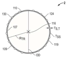
이제 도 1a 및 도 1b를 참조하면, 공차 링은 2로 일반적으로 지정되어 나타나 있다. 도 1a에 도시된 바와 같이, 공차 링(2)은, 일반적으로 미변형된 원통형 측벽(104)을 갖는 몸체(4)를 포함할 수 있다. 측벽(104)은, 제1 축 말단에 위치한 상부(106), 및 상기 제1 축 말단에 대향하는 제2 축 말단에 위치한 하부(108)를 포함할 수 있다. 도 1b에 도시된 바와 같이, 측벽(104)은, 제1 반경 측부에 위치한 내측부(107), 및 상기 제1 반경 측부에 대향하는 제2 반경 측부에 위치한 외측부(109)를 포함할 수 있다. 또한 다수의 구현예에서, 측벽(104)은 제1 말단 또는 에지(110), 및 제2 말단 또는 에지(112)를 포함할 수 있다. 또한, 상기 측벽(104)의 제1 말단(110)과 제2 말단(112) 사이에 갭(114)을 형성할 수 있다. 상기 공차 링(2)의 측벽(104)에 스플릿을 형성하기 위해, 갭(114)은 측벽(104)을 통해 완전히 연장될 수 있다. 도 1b에 나타낸 바와 같이, 공차 링(2)은 스플릿을 포함할 수 없고 폐루프 튜브 또는 실린더일 수 있다. 도 1a 및 도 1b에 나타낸 바와 같이, 공차 링(2)은 중심축(116)을 포함할 수 있다. Referring now to FIGS. 1A and 1B, the tolerance ring is generally designated 2. As shown in FIG. 1A, the
다수의 구현예에서, 공차 링(2)은 두께(T)를 가질 수 있고, T는 0.1 mm 이상, 예컨대 0.2 mm 이상, 0.3 mm 이상, 0.4 mm 이상, 0.5 mm 이상, 또는 0.6 mm 이상일 수 있다. 다른 양태에서, T는 1.0 mm 이하, 0.9 mm 이하, 또는 0.8 mm 이하일 수 있다.In many embodiments, the
다수의 구현예에서, 공차 링(2)은 전체 외경(OD)을 가질 수 있고, OD는 1 mm 이상, 예컨대 10 mm 이상, 20 mm 이상, 30 mm 이상, 40 mm 이상, 또는 50 mm 이상일 수 있다. OD는 100 mm 이하, 예컨대 50 mm 이하, 또는 25 mm 이하일 수 있다.In many embodiments, the
다수의 구현예에서, 공차 링은, 제1 축 말단(106)에서 제2 축 말단(108)까지의 전체 길이(L)를 가질 수 있고, L은 1 mm 이상, 5 mm 이상, 10 mm 이상, 25 mm 이상, 50 mm 이상일 수 있다. L은 75 mm 이하, 예컨대 50 mm 이하, 25 mm 이하, 10 mm 이하, 또는 5 mm 이하일 수 있다.In many embodiments, the tolerance ring can have an overall length L from the first
공차 링(2)의 측벽(104)은 적어도 하나의 중간 부위(119)를 포함할 수 있다. 공차 링(2)의 측벽(104)은, 측벽(104)의 상부(106) 근처 또는 이에 인접한 상부 중간 부위(120)를 포함할 수 있다. 측벽(104)은, 측벽(104)의 하부(108) 근처 또는 이에 인접한 적어도 하나의 하부 중간 부위(122)를 또한 포함할 수 있고, 상기 적어도 하나의 상부 중간 부위(120)에 대향한다. 또한, 중심 중간 부위(124)는, 상기 상부 및 하부 중간 부위(120 및 122) 사이에서 측벽(104)의 길이를 따라 축방향으로 연장될 수 있고, 이들로부터 연장될 수 있다. 다수의 구현예에서, (상부 중간 부위(120), 하부 중간 부위(122) 및/또는 중심 중간 부위(124)를 포함하는) 중간 부위(119)는 윤곽이 있거나 경사진 형상을 포함할 수 있다. 다수의 구현예에서, (상부 중간 부위(120), 하부 중간 부위(122) 및/또는 중심 중간 부위(124)를 포함하는) 중간 부위(119)는 미형성된 형상을 포함할 수 있다.The
도 1a 및 도 1b에 나타낸 바와 같이, 공차 링(2)은, 측벽(104)에 형성된 파형 구조를 포함하는 복수의 파형 구조 부위(130)를 포함할 수 있다. 파형 구조 부위(130)는, 공차 링(2)의 중심축(116)에서 멀리 또는 중심축을 향해, 측벽(104)에서 반경 방향 외측 또는 내측으로 돌출할 수 있다. 다수의 구현예에서, 파형 구조 또는 파형 구조 부위(130)는 다각형, 타원형, 원형, 반원형, 또는 실질적인 원형, 또는 뾰족한 단면을 가질 수 있고, 그 형상과 일치할 수 있다. 특정 구현예에서, 파형 구조 또는 파형 구조 부위(130)는, 도 2 및 도 3에 나타낸 바와 같이, 뾰족한 정점(131)을 갖는 삼각형 단면 형상을 가질 수 있다. 다수의 구현예에서, 파형 구조 또는 파형 구조 부위(130)는 정다각형을 포함할 수 있고, 즉 파형 구조 또는 파형 구조 부위(130)는 등각과 등변일 수 있는 다각형일 수 있다. 1A and 1B, the
각각의 파형 구조 부위(130)는 중간 부위(124)에만 연결될 수 있어 파형 구조(130)의 중간 밴드(120 및 122) 근처의 부분이 개방되도록 한다. 다른 구현예에서, 파형 구조 부위(130)는 미변형된 부위(124)와 미변형된 밴드(120 및 122)에 연결될 수 있어 이들이 폐쇄되도록 한다. 도 1b에 나타낸 바와 같이, 각각의 중간 부위(124)는 인접한 파형 부위(130) 사이에 위치할 수 있고, 각각의 파형 구조 부위(130)는 인접한 형성 부위(124) 사이에 위치할 수 있어서, 파형 구조 부위(130)와 중간 부위(124)는 측벽(104)의 원주 주위에서 교번한다.Each
도 1a에 도시된 바와 같이, 공차 링(2)은 파형 구조가 하나인 행 또는 밴드를 포함할 수 있다. 다른 구현예(미도시)에서, 공차 링은 두 개의 행 또는 밴드의 파형 구조, 세 개의 행 또는 밴드의 파형 구조 등을 포함할 수 있다. 또한 각 행에서 파형 구조 또는 파형 구조 부위의 총 갯수(NWS)는 3 이상, 예컨대 4 이상, 5 이상, 6 이상, 7 이상, 8 이상, 또는 9 이상일 수 있다. 또한, NWS는 30 이하, 25 이하, 20 이하, 또는 15 이하일 수 있다. NWS는 상기 NWS 값 사이의 범위 내일 수 있거나, 이를 포함할 수 있다. 특정 구현예에서, 도 1a 및 도 1b에 나타낸 바와 같이 NWS는 15일 수 있다.As shown in FIG. 1A, the
이제 도 2 및 도 3을 참조하면, 다수의 구현예에서, 본원에 설명된 구현예 중 하나 이상에 따른 공차 링(2)은, (샤프트와 같은) 내부 부재(28)와 (하우징과 같은) 외부 부재(30) 사이에 중심축(116)을 따라 배치되어 설치 상태에서 공차 링을 갖는 어셈블리(1)를 형성할 수 있다. 내부 구성 요소(28)와 외부 구성 요소(30)는, 당업계에 공지된 금속, 폴리머, 또는 다른 유사한 재료를 포함하는 재료로부터 각각 형성될 수 있다. 도 2 및 도 3 그리고 도 9 및 도 10에 나타낸 바와 같이, 다수의 구현예에서, 공차 링(2)의 대향하는 제1 및 제2 에지(110, 112) 중 적어도 하나는 외부 부재(30)와 체결하고/체결하거나 접촉할 수 있다. 다수의 구현예에서, 제1 및 제2 에지(110, 112) 중 적어도 하나는 외부 부재(30)와 체결되어 공차 링(2)과 외부 부재(30) 사이에서 상대적 이동을 방지하거나 제한할 수 있다. 상기 이동은, 중심축(116)에 대해 회전 방향, 축 방향, 또는 반경 방향으로 방지되거나 제한될 수 있다. 특정 구현예에 따라, 상대적인 반경 방향의 이동이 방지된다. 도 2 그리고 도 9 및 도 10에 나타낸 바와 같이, 다수의 구현예에서, 공차 링(2)의 대향하는 제1 및 제2 에지(110, 112) 중 적어도 하나는 내부 부재(28) 또는 외부 부재(30) 중 적어도 하나와 인터로크를 형성할 수 있다. 다수의 구현예에서, 인터로크는, 내부 부재(28) 또는 외부 부재(30) 중 적어도 하나와 접촉하는 에지(110, 112) 중 적어도 하나의 코너(111)일 수 있다. 다수의 구현예에서, 도 3에 나타낸 바와 같이, 공차 링(2)의 대향하는 제1 및 제2 에지(110, 112) 중 적어도 하나는, 내부 부재(28) 또는 외부 부재(30)에서 발견되는 매칭 요소 또는 달리 그루브(113, 113')를 통해 내부 부재(28) 또는 외부 부재(30) 중 적어도 하나에 연결될 수 있다. 다수의 변형예에서, 그루브(113, 113')는 다각형, 타원형, 원형, 반원형, 또는 실질적인 원형 단면을 가질 수 있고, 제1 또는 제2 에지(110, 112) 중 적어도 하나의 형상과 일치하여 내부 부재(28) 또는 외부 부재(30) 중 적어도 하나와 함께 공차 링(2)의 상대적 이동을 방지하거나 제한하는 간섭 끼워맞춤을 형성할 수 있다. Referring now to FIGS. 2 and 3, in a number of embodiments, the
도 2 및 도 3을 계속 참조하면, 다수의 구현예에서, 공차 링은 내부 부재(28)와 외부 부재(30) 사이에 설치시 변형될 수 있어서, 어셈블리(1)에 설치되는 경우에 측벽(104)에서 복수의 측벽 세그먼트(6)를 형성하도록 한다. 다수의 구현예에서, 이들 측벽 세그먼트(6)는 적어도 하나의 좌굴 부위(35)를 포함할 수 있고, 이는 어셈블리(1)에 설치시 내부 부재(28)와 외부 부재(30) 사이의 간섭 끼워맞춤으로 인해 변형될 수 있다. 미설치 상태에서, 좌굴 부위(35)는 도 1a 및 도 1b에 나타낸 바와 같이 비평면일 수 있다. 조립 또는 사용 중에, 좌굴 부위(35)의 일부는 설치 상태에서 일반적으로 평면일 수 있다. 다수의 구현예에서, 좌굴 부위는, 내부 부재(28) 또는 외부 부재(30) 중 적어도 하나를 접촉할 수 있다. 다수의 구현예에서, 좌굴 부위는, 외부 부재(30)와 하나의 접촉점을 그리고 내부 부재(28)와 두 개의 접촉점을 형성하도록 조정될 수 있다. 이 좌굴 부위(35)는, 도 1a 및 도 1b에 나타낸 바와 같이 공차 링(2)이 미설치된 상태에서는(즉, 공차 링(2)이 내부 부재(28)와 외부 부재(30) 사이에 배치될 수 있기 전에는) 존재할 수 없다. 좌굴 부위(35)는 적어도 부분적으로 탄성 변형될 수 있어서, 내부 부재(28)와 외부 부재(30)로부터 분리시, 좌굴 부위가 적어도 부분적으로 붕괴되도록 한다. 도 2 및 도 3에 나타낸 바와 같이, 좌굴 부위(35)는 좌굴 부위 높이(HBR)를 가질 수 있고, 분리시 좌굴 부위 높이(HBR)는 80% 이하, 예컨대 70% 이하, 60% 이하, 50% 이하, 40% 이하, 30% 이하, 20% 이하, 10% 이하, 또는 5% 이하 정도로 감소할 수 있다. 좌굴 부위(35)의 높이(HBR)는 중간 부위(119)와 동일한 기울기이거나 윤곽선일 수 있다.2 and 3, in many implementations, the tolerance ring can be deformed upon installation between the
조립시, 좌굴 부위(35) 중 적어도 하나는 변형의 탄성 구역에서 작동할 수 있고, 즉 좌굴 부위(35) 중 적어도 하나는 힘이 인가될 시 변형할 수 있고 힘이 제거된 이후 원래 형상으로 복귀할 수 있다. 다른 변형 특성의 좌굴 부위(35)를 포함함으로써, 공차 링(2)의 특성, 예를 들어 강성, 활주 능력, 또는 공차 흡수를 추가로 변경하는 것이 가능할 수 있다.Upon assembly, at least one of the buckling
다수의 구현예에서, 도 2 및 도 3에 나타낸 바와 같이, 좌굴 부위(35)는, 설치 상태에서 내부 부재(28)와 외부 부재(30) 사이에 공차 링(2)을 조립 및 사용하는 중에 중간 부위(119 (120, 122, 124)) 중 적어도 하나로부터 형성될 수 있다. 좌굴 부위(35)는, 내부 부재(28)와 외부 부재(30) 사이에 설치되는 경우이거나 내부 부재(28)와 외부 부재(30) 중 적어도 하나에 힘(예, 회전 방향 힘, 축 방향 힘, 또는 반경 방향 힘)이 인가되는 중에 형성될 수 있다. In many embodiments, as shown in FIGS. 2 and 3, the buckling
다수의 구현예에서, 어셈블리(1)에 설치시, 측벽 세그먼트(6)는, 공차 링(2)의 좌굴 부위(35)를 형성하거나 달리 포함할 수 있고, 각각의 좌굴 부위(35)는, 내부 부재(28) 또는 외부 부재(30)와 접촉하는 정점, 고평부, 또는 마루부(7)를 형성한다. 다수의 구현예에서, 어셈블리(1)에 설치시, 측벽 세그먼트(6)는, 공차 링(2)의 좌굴 부위(35)를 형성하거나 달리 포함할 수 있고, 각각의 좌굴 부위(35)는, 내부 부재(28) 또는 외부 부재(30)와 접촉하지 않는 정점, 고평부, 또는 마루부(7)를 형성한다. 다수의 구현예에서, 정점(7)은 둥글 수 있다. 다수의 구현예에서, 정점(7)은 뾰족할 수 있다. 다수의 구현예에서, 어셈블리(1) 내에 공차 링(2)을 설치하거나 사용하는 중에 버클링된 좌굴 부위(35)는 측벽 세그먼트(6)를 형성할 수 있다. 측벽 세그먼트(6)는 파형 구조 부위(130) 사이에 있을 수 있거나 하나의 파형 구조 부위(30) 중 적어도 일부를 포함할 수 있다. 다수의 구현예에서, 각각의 측벽 세그먼트(6) 중 적어도 65%는 평면을 따라 배치될 수 있고, 예컨대 각각의 측벽 세그먼트 중 적어도 70%, 각각의 측벽 세그먼트 중 적어도 75%, 각각의 측벽 세그먼트 중 적어도 80%, 각각의 측벽 세그먼트 중 적어도 85%, 각각의 측벽 세그먼트 중 적어도 90%, 또는 각각의 측벽 세그먼트(6) 중 적어도 95%는 평면을 따라 배치될 수 있다.In many embodiments, when installed in the assembly 1, the
다수의 구현예에서, 각각의 측벽 세그먼트(6)는 두께(TSS)와 높이 (HSS)를 정의할 수 있다. 특정 구현예에서, 측벽 세그먼트(6)의 두께에 대한 측벽 세그먼트(6)의 높이 비율로 측정되는 바와 같이, 종횡비는 1.5:1 미만일 수 있다. 특정 구현예에서, 좌굴 부위(35)는 적어도 3개의 측벽 세그먼트, 예컨대 적어도 4개의 측벽 세그먼트, 적어도 5개의 측벽 세그먼트, 적어도 6개의 측벽 세그먼트, 적어도 7개의 측벽 세그먼트, 적어도 8개의 측벽 세그먼트, 적어도 9개의 측벽 세그먼트, 적어도 10개의 측벽 세그먼트, 적어도 15개의 측벽 세그먼트, 또는 심지어 적어도 20개의 측벽 세그먼트를 포함할 수 있다. 추가 구현예에서, 공차 링은 75 이하의 측벽 세그먼트, 예컨대 50 이하의 측벽 세그먼트, 또는 심지어 25 이하의 측벽 세그먼트를 포함할 수 있다. 이 관점에서 상부도에서 보는 경우, 예컨대 도 2 및 도 3에 나타낸 바와 같이, 공차 링(2)은, 예를 들어 삼각형, 사변형, 오각형, 육각형, 칠각형, 팔각형, 구각형, 십각형 등과 같은 다각형을 정의할 수 있다.In a number of implementations, each
본 명세서를 읽은 후, 공차 링(2)의 좌굴 부위(35)를 포함한 측벽 세그먼트(6)의 갯수는, 어셈블리의 내부 부재와 외부 부재 사이에 형성된 반경 방향의 갭(105)의 두께에 의존할 수 있음을 당업자는 이해할 것이다. 예를 들어, 아래에 더 자세히 설명되는 바와 같이, 대형 반경 방향 갭(105)을 갖는 어셈블리(1)는 측벽 세그먼트(6)를 덜 사용할 수 있고, 더 많은 측벽 세그먼트(6)가 요구될 수 있는 소형 반경 방향 갭(105)을 갖는 어셈블리(1)에 비교된다.After reading this specification, the number of
다수의 구현예에서, 도 4에 나타낸 바와 같이, 공차 링(2)은 복합 재료를 포함할 수 있다. 다수의 구현예에서, 공차 링(2)은, 기재 또는 금속 스트립(1119), 및 저마찰층(1104)을 포함할 수 있다. 저마찰층(1104)은 금속 스트립(1119)의 적어도 일부에 결합될 수 있다. 특정 구현예에서, 저마찰층(1104)은 금속 스트립(1119)의 표면에 결합되어, 다른 구성 요소의 다른 표면과 마찰이 적은 인터페이스를 형성할 수 있다. 특정 구현예에서, 저마찰층(1104)은 금속 스트립(1119)의 반경 방향 내부 표면에 결합되어, 다른 구성 요소의 다른 표면과 마찰이 적은 인터페이스를 형성할 수 있다. 특정 구현예에서, 저마찰층(1104)은 금속 스트립(1119)의 반경 방향 외부 표면에 결합되어, (내부 부재(28) 또는 외부 부재(30)와 같은) 다른 구성 요소의 다른 표면과 마찰이 적은 인터페이스를 형성할 수 있다.In many embodiments, as shown in FIG. 4, the
일 구현예에서, 금속 스트립(1119)은 적어도 부분적으로 금속을 포함할 수 있다. 상기 금속은 알루미늄, 아연, 구리, 마그네슘, 주석, 백금, 티타늄, 텅스텐, 납, 철, 청동, 이들의 합금을 포함할 수 있거나 또는 다른 유형일 수 있다. 보다 구체적으로, 기재는 적어도 부분적으로 스틸, 예컨대 스테인리스강 또는 스프링강을 포함할 수 있다. 예를 들어, 기재는 적어도 부분적으로 301 스테인리스강을 포함할 수 있다. 301 스테인리스강은 어닐링, ¼ 경화, ½ 경화, ¾ 경화, 또는 완전 경화될 수 있다. 금속 스트립(1119)은 직조형 메쉬 또는 확장형 금속 그리드를 포함할 수 있다. 대안적으로, 직조형 메쉬는 직조형 폴리머 메쉬일 수 있다. 대안적인 구현예로서, 금속 스트립(1119)은 메쉬 또는 그리드를 포함하지 않을 수 있다. 대안적인 또 다른 구현예에서, 고체 구성 요소, 직조형 메쉬 또는 확장형 금속 그리드로서의 금속 스트립(1119)은, 저 마찰층(1104)과 금속 스트립(1119) 사이에 포함된 적어도 하나의 접착제층(1121) 사이에 내장될 수 있다. 적어도 하나의 구현예에서, 금속 스트립(1119)은 임의 종류의 금속 합금일 수 있고, 이는 아치 형상으로 부하를 인가하는 경우 탄성 거동을 제공한다.In one embodiment, the
선택적으로, 공차 링(2)은, 저마찰층(1104)을 금속 스트립(1119)에 결합시킬 수 있는 적어도 하나의 접착제층(1121)을 포함할 수 있다. 접착제층(1121)은, 상기 링 기술에 보편적이고 공지된 임의 재료를 포함하나 이에 제한되지 않는 플루오로폴리머, 에폭시 수지, 폴리이미드 수지, 폴리에테르/폴리아미드 공중합체, 에틸렌 비닐 아세테이트, 에틸렌 테트라플루오로에틸렌(ETFE), ETFE 공중합체, 퍼플루오로알콕시(PFA), 또는 이의 임의 조합물을 포함할 수 있다. 추가적으로, 접착제는 -C=O, -C-O-R, -COH, -COOH, -COOR, -CF2=CF-OR(여기서 R은 고리형 또는 선형 유기기로 1 내지 20의 탄소 원자를 함유함), 또는 이들의 임의 조합으로부터 선택된 적어도 하나의 관능기를 포함할 수 있다. 추가적으로, 접착제는 공중합체를 포함할 수 있다. 일 구현예에서, 핫멜트 접착제는 250°C 이하, 예컨대 220°C의 융점을 가질 수 있다. 다른 구현예에서, 접착제는 200°C 초과, 예컨대 220°C 초과에서 녹을 수 있다. 추가 구현예에서, 핫멜트 접착제의 융점은 250°C 초과 또는 심지어 300°C 초과일 수 있다. 접착제층(1121)은 약 1 내지 50 마이크론, 예컨대 약 7 내지 15 마이크론의 두께를 가질 수 있다.Optionally, the
선택적으로, 금속 스트립(1119)은 부식 방지층(1704 및 1705)으로 코팅되어 프로세싱 전에 공차 링(2)의 부식을 방지할 수 있다. 추가적으로, 부식 방지층(1708)이 층(1704) 위에 도포될 수 있다. 층(1704, 1705, 1708) 각각은 약 1 내지 50 마이크론, 예컨대 약 7 내지 15 마이크론의 두께를 가질 수 있다. 층(1704 및 1705)은, 아연, 철, 망간의 인산염 또는 이들의 임의 조합, 또는 나노 세라믹층을 포함할 수 있다. 또한, 층(1704 및 1705)은 기능성 실란, 나노 크기의 실란 기반 프라이머, 가수분해된 실란, 유기실란 접착 촉진제, 용제/수성 기반 실란 프라이머, 염화 폴리올레핀, 부동태화 표면, 상용 가능한 아연(기계적/갈바닉) 또는 아연-니켈 코팅, 또는 이들의 임의 조합을 포함할 수 있다. 층(1708)은 기능성 실란, 나노 크기의 실란 기반 프라이머, 가수분해된 실란, 유기실란 접착 촉진제, 용제/수성 기반 실란 프라이머를 포함할 수 있다. 부식 방지층(1704, 1706, 및 1708)은 프로세싱 중에 제거 또는 유지될 수 있다.Optionally, the
선택적으로, 공차 링(2)은 내부식 코팅(1125)을 추가로 포함할 수 있다. 내부식 코팅(1125)은 약 1 내지 50 마이크론, 예컨대 약 5 내지 20 마이크론, 및 예컨대 약 7 내지 15 마이크론의 두께를 가질 수 있다. 내부식 코팅은 접착 촉진제층(127)과 에폭시층(129)을 포함할 수 있다. 접착 촉진제층(1127)은 아연, 철, 망간, 주석의 인산염 또는 이들 임의의 조합, 또는 나노 세라믹층을 포함할 수 있다. 접착 촉진제층(1127)은 기능성 실란, 나노 크기의 실란 기반 프라이머, 가수분해된 실란, 유기실란 접착 촉진제, 용제/수성 기반 실란 프라이머, 염화 폴리올레핀, 부동태화 표면, 상용 가능한 아연(기계적/갈바닉) 또는 아연-니켈 코팅, 또는 이들의 임의 조합을 포함할 수 있다. 에폭시층(1129)은 열경화 에폭시, UV 경화 에폭시, IR 경화 에폭시, 전자빔 경화 에폭시, 복사선 경화 에폭시, 또는 공기 경화 에폭시일 수 있다. 추가로, 에폭시 수지는 폴리글리시딜에테르, 디글리시딜에테르, 비스페놀 A, 비스페놀 F, 옥시란, 옥사시클로프로판, 에틸렌옥사이드, 1,2-에폭시프로판, 2-메틸옥시란, 9,10-에폭시-9,10-디히드로안트라센, 또는 이들의 임의 조합을 포함할 수 있다. 에폭시 수지층(1129)은 경화제를 추가로 포함할 수 있다. 경화제는 아민, 무수물산, 페놀 노볼락 폴리[N-(4-히드록시페닐)말레이미드](PHPMI)와 같은 페놀 노볼락 경화제, 레졸 페놀 포름알데히드, 지방 아민 화합물, 무수화 폴리카본, 폴리아크릴레이트, 이소시아네이트, 캡슐화 폴리이소시아네이트, 보론 트리플루오라이드 아민 복합체, 크롬 기반 경화제, 폴리아미드, 또는 이들의 임의 조합을 포함할 수 있다. 일반적으로, 무수물산은 화학식 R-C=O-O-C=O-R’일 수 있고, 여기서 R은 전술한 대로 CXHYXZAU일 수 있다. 아민은, 모노에틸아민, 디에틸렌트리아민, 트리에틸렌테트라아민 등과 같은 지방족 아민, 지방족 고리의 아민, 방향족 아민, 예컨대 환형 지방족 아민, 지방족 고리의 아민, 아미도아민, 폴리아미드, 디시안디아미드, 이미다졸 유도체 등 또는 이들의 임의 조합을 포함할 수 있다.Optionally, the
다수의 구현예에서, 저마찰층(1104)은, 예를 들어 폴리머, 예컨대 폴리케톤, 폴리아라미드, 폴리이미드, 폴리에테르이미드, 폴리페닐렌 설파이드, 폴리에테르술폰, 폴리술폰, 폴리페닐렌 술폰, 폴리아미드이미드, 초고분자량 폴리에틸렌, 플루오로폴리머, 폴리아미드, 폴리벤지미다졸, 또는 이들의 임의 조합물을 포함하는 재료를 포함할 수 있다. 일 구현예에서, 저마찰층(1104)은 폴리케톤, 폴리아라미드, 폴리이미드, 폴리에테르이미드, 폴리아미드이미드, 폴리페닐렌 설파이드, 폴리페닐렌 술폰, 플루오로폴리머, 폴리벤지미다졸, 이들의 유도체, 또는 이들의 조합물을 포함한다. 특정 구현예에서, 저마찰/내마모층은 폴리머, 예컨대 폴리케톤, 열가소성 폴리이미드, 폴리에테르이미드, 폴리페닐렌 설파이드, 폴리에테르 술폰, 폴리술폰, 폴리아미드이미드, 이들의 유도체, 또는 이들의 조합물을 포함한다. 추가예로서, 저마찰/내마모층은 폴리케톤, 예컨대 폴리에테르 에테르 케톤(PEEK), 폴리에테르 케톤, 폴리에테르 케톤 케톤, 폴리에테르 케톤 에테르 케톤, 이들의 유도체, 또는 이들의 조합물을 포함한다. 추가예로서, 저마찰/내마모층은 초고분자량 폴리에틸렌일 수 있다. 플루오로폴리머의 예는, 불소화 에틸렌 프로필렌(FEP), 폴리테트라플루오로에틸렌(PTFE), 폴리비닐이덴 플루오라이드(PVDF), 퍼플루오로알콕시(PFA), 테트라플루오르 에틸렌/헥사플루오로프로필렌/비닐이덴플루오라이드의 삼원 중합체(THV), 폴리클로로트리플루오로에틸렌(PCTFE), 에틸렌 테트라플루오로에틸렌 공중합체(ETFE), 에틸렌 클로로트리플루오로에틸렌 공중합체(ECTFE), 폴리아세탈, 폴리부틸렌 테레프탈레이트(PBT), 폴링틸렌 테레프탈레이트(PET), 폴리이미드(PI), 폴리에테르이미드, 폴리에테르에테르케톤(PEEK), 폴리에틸렌(PE), 폴리술폰, 폴리아미드(PA), 폴리페닐렌 옥사이드, 폴리페닐렌 설파이드(PPS), 폴리우레탄, 폴리에스테르, 액정 폴리머(LCP) 또는 임의의 조합물을 포함한다. 저마찰층(1104)은, 리튬 비누, 그래파이트, 보론 나이트라이드, 몰리브덴 디설파이드, 텅스텐 디설파이드, 폴리테트라플루오로에틸렌, 카본 나이트라이드, 텅스텐 카바이드, 또는 다이아몬드 유사 카본, (알루미늄, 아연, 구리, 마그네슘, 백금, 티타늄, 텅스텐, 납, 철, 청동, 스틸, 스프링강, 스테인리스강과 같은) 금속, (열거된 금속을 포함하는) 금속 합금, (열거된 금속 합금을 포함하는) 아노다이징된 금속 또는 이들의 조합물을 포함하는 고체 기반 재료를 포함할 수 있다. 특정 구현예에 따라 플루오로폴리머를 사용할 수 있다. 본원에 사용되는 바와 같이, "저마찰 재료"는 스틸에 대해 0.5 미만, 예컨대 0.4 미만, 0.3 미만, 또는 심지어 0.2 미만으로 측정된 정적 건조 마찰 계수를 갖는 재료일 수 있다. "고마찰 재료"는 스틸에 대해 0.6 초과, 예컨대 0.7 초과, 0.8 초과, 0.9 초과, 또는 심지어 1.0 초과로 측정된 정적 건조 마찰 계수를 갖는 재료일 수 있다.In many embodiments, the
다수의 구현예에서, 저마찰층(1104)은, 유리 섬유, 탄소 섬유, 실리콘, PEEK, 방향족 폴리에스테르, 탄소 입자, 청동, 플루오로폴리머, 열가소성 필러, 알루미늄 옥사이드, 폴리아미드이미드(PAI), PPS, 폴리페닐렌 술폰(PPSO2), LCP, 방향족 폴리에스테르, 몰리브덴 디설파이드, 텅스텐 디설파이드, 그래파이트, 그래핀, 확장된 그래파이트, 보론 나이트라이드, 활석, 칼슘 플루오라이드, 또는 이들의 임의 조합물을 포함하는 필러를 추가로 포함할 수 있다. 또한, 필러는 알루미나, 실리카, 티타늄 디옥사이드, 칼슘 플루오라이드, 보론 나이트라이드, 마이카, 올라스토나이트, 실리콘 카바이드, 실리콘 나이트라이드, 지르코니아, 카본 블랙, 피그먼트, 또는 이들의 조합물을 포함할 수 있다. 필러는 비드, 섬유, 분말, 메쉬, 또는 이들의 임의 조합 형태일 수 있다.In many embodiments, the
일 구현예에서, 저마찰층(1104)은 0.01 mm 내지 0.4 mm의 범위, 예컨대 0.15 mm 내지 0.35 mm 범위, 또는 심지어 0.2 mm 내지 0.3 mm 범위인 두께(TFL)를 가질 수 있다. 일 구현예에서, 저마찰층(1104)의 두께는 균일할 수 있고, 즉 저마찰층(1104)의 제1 위치에서의 두께는 길이를 따라 제2 위치에서의 두께와 동일할 수 있다. 일 구현예에서, 공차 링(2)은 금속 스트립(1119)을 포함할 수 있고, 이는 측벽(104)의 외측부(109)에서 저마찰층(1104)으로 형성될 수 있다. 일 구현예에서, 공차 링(2)은 금속 스트립(1119)을 포함할 수 있고, 이는 측벽(104)의 내측부(107)에서 저마찰층(1104)으로 형성될 수 있다. 다수의 구현예에서, 금속 스트립(1119)은 공차 링(2)의 길이를 따라 적어도 부분적으로 연장될 수 있다. 금속 스트립(1119)은 저마찰 또는 저마찰층(1104)에 의해 적어도 부분적으로 캡슐화될 수 있다. 즉, 저마찰 또는 저마찰층(1104)은 금속 스트립(1119)의 적어도 일부를 덮을 수 있다. 금속 스트립(1119)의 축 말단은 저마찰 또는 저마찰층(1104)으로부터 노출되거나 노출되지 않을 수도 있다. 특정 구현예에서, 금속 스트립(1119)은 저마찰 또는 저마찰층(1104)에 완전히 캡슐화되어 금속 스트립(1119)이 시각적으로 인지되지 않을 수 있도록 한다. 다른 구현예에서, 금속 스트립(1119)은 저마찰 또는 저마찰층(1104) 내로 적어도 부분적으로 연장되는 애퍼처를 포함할 수 있다. 애퍼처는 일반적으로 공차 링(2)의 강성을 감소시킴으로써, 특정하게 엔지니어링된 강성 프로파일을 허용할 수 있다.In one embodiment, the
일 구현예에서, 전술한 바와 같이, 공차 링(2) 상의 임의 층은 각각 롤로 배치되고 이들로부터 벗겨져 고온 압력 하에 접착제 또는 이들의 임의 조합으로 서로 결합할 수 있다(고온 또는 저온 가압 또는 롤 방식). 다수의 구현예에서, 전술한 바와 같이, 공차 링(2)의 임의 층은 서로 적층화되어 적어도 부분적으로 서로 중첩될 수 있다. 다수의 구현예에서, 전술한 바와 같이, 공차 링(2)의 임의 층은, 코팅 기법, 예컨대 물리 또는 기상 증착, 스프레이법, 플레이팅법, 분말 코팅법을 사용하거나 다른 화학적 또는 전기화학적 기법을 통해 서로 도포될 수 있다. 특정 구현예에서, 저마찰층(1104)은, 예를 들어 압출 코팅을 포함하는 롤-투-롤 코팅에 의해 도포될 수 있다. 저마찰층(1104)은 용융 또는 반용융 상태로 가열되어 슬롯 다이를 통해 금속 스트립(119)의 주 표면 상으로 압출될 수 있다. 다른 구현예에서, 저마찰층(1104)은 주조 또는 성형될 수 있다.In one embodiment, as described above, any layer on the
다른 구현예에서, 전술한 바와 같이, 공차 링(2) 상의 임의 층은, 코팅 기법, 예컨대 물리 또는 기상 증착, 스프레이법, 플레이팅법, 분말 코팅법에 의하거나 다른 화학적 또는 전기화학적 기법을 통해 도포될 수 있다. 특정 구현예에서, 저마찰층(1104)은, 예를 들어 압출 코팅을 포함하는 롤-투-롤 코팅에 의해 도포될 수 있다. 저마찰층(1104)은 용융 또는 반용융 상태로 가열되어 슬롯 다이를 통해 기재 또는 금속 스트립(119)의 주 표면 상으로 압출될 수 있다. 다른 구현예에서, 저마찰층(1104)은 주조 또는 성형될 수 있다.In another embodiment, as described above, any layer on the
비제한적인 예로서, 공차 링(2)은 지그로 형상화될 수 있다. 전술한 바와 같이, 이 관점에서 탄성 재료 스트립은 지그에서 원하는 위치에서 굽혀 만곡부를 형성할 수 있다. 탄성 재료 스트립은, (알루미늄, 아연, 구리, 마그네슘, 백금, 티타늄, 텅스텐, 납, 철, 청동, 스틸, 스프링강, 스테인리스강과 같은) 금속, (열거된 금속을 포함하는) 금속 합금, (열거된 금속 합금을 포함하는) 아노다이징된 금속 또는 이들의 조합물을 포함하는 기재(1119)를 포함할 수 있다. 비제한적 구현예에서, 탄성 재료의 스트립은 추가적이거나 대안적으로, 탄성 재료 또는 기재 상에 배치된 폴리머 또는 폴리머 코팅을 포함하는 저마찰층(1104)을 포함할 수 있다. 다수의 구현예에서, 대안적인 재료는 공차 링(2)의 원주를 따라 사용될 수 있다. 즉, 좌굴 부위(35), 중간 부위(119), 및 파형 구조 부위(130)는 각각 공차 링(2)을 중심으로 원주 방향, 반경 방향, 또는 축 방향으로 다양한 위치에서 위에 전술한 상이한 재료 또는 재료 성분을 포함할 수 있다.As a non-limiting example, the
특정 구현예에서, 전술한 바와 같이, 공차 링(2)은 공차 링(2)의 원주 말단 사이에 배치된 원주형 갭(114)을 추가적으로 정의할 수 있다. 원주형 갭(114)은, 분리된 공차 링(2)을 형성하도록 공차 링(2)의 전체 축 길이를 연장할 수 있다. 특정 응용에서, 원주형 갭(114)은, 공차 링(2)의 원주 말단을 따라 하나 이상의 위치에서 서로 용접될 수 있다. 용접부(들)는 영구적이거나 일시적일 수 있다. 공차 링(2)의 운반 중에 공차 링의 얽힘을 방지하기 위해 일시적인 용접을 사용할 수 있다. 대안적으로, 용접부는 폐쇄된 공차 링을 형성하기 위해 영구적일 수 있다. 대안적으로, 공차 링은 도 1b에 나타낸 바와 같이 갭이 전혀 없이 형성되거나 용접을 통해 전혀 갭이 없을 수 있다.In certain embodiments, as described above, the
다수의 구현예에서, 좌굴 부위(35)의 측벽 세그먼트(6)는, 설치 상태에서 좌굴 부위(35)의 정점(7)에서 각도(A)로 만날 수 있다(도 2 및 도 3의 8에 나타냄) 특정 구현예에서 각각의 각도(8)는 60° 이상, 예컨대 90° 이상, 120° 이상, 또는 심지어 150° 이상일 수 있다. 추가 구현예에서, 각각의 각도(8)는 180° 이하, 예컨대 170° 이하, 160° 이하, 150° 이하, 140° 이하, 130° 이하, 120° 이하, 또는 심지어 110° 이하일 수 있다. 특정 구현예에서, 각도(8)는 실질적으로 평행한 방향으로 연장되는 직선을 따라 모두 놓일 수 있다. 본원에 사용되는 바와 같이, "실질적으로 평행한 방향"은 두 선의 측정 방향 사이가 5° 이하, 예컨대 4°이하, 3° 이하, 또는 심지어 약 2° 이하의 편차를 지칭한다. 보다 특정한 구현예에서, 각도(8)는 평행하게 연장되는 선을 따라 모두 놓일 수 있다. 본원에 사용되는 바와 같이, "평행하게 연장되는"은 두 선의 측정 방향 사이가 0.5° 이하의 편차를 지칭한다. 이 관점에서, 측벽 세그먼트(6)는 각각 평행한 원주 말단 선을 가질 수 있다.In many embodiments, the
특정 구현예에서, 설치 상태의 상부도를 보는 경우, 공차 링(2)은 정다각형을 포함할 수 있고, 즉 공차 링(2)은 등각 및 등변일 수 있는 다각형일 수 있다. 정다각형은, 이의 측벽 갯수와 동일한 회전 대칭 배향 갯수를 갖는 n-회전 대칭을 일반적으로 갖는다. 예를 들어, 정삼각형은 3개의 회전 대칭점을 갖고, 정사각형은 4개의 회전 대칭점을 갖고, 정오각형은 5개의 회전 대칭점을 갖는다 등등. 특정 구현예에서, 정다각형은, 반경 방향의 불균일한 부하 상태 및 임의의 원하지 않는 편심 작동 효과를 피하기 위해, 공차 링(2)의 주위에 부하 상태를 균일하게 배치시킬 수 있다.In certain embodiments, when viewing the top view of the installation state, the
특정 구현예에서, 좌굴 부위(35)의 측벽 세그먼트(6) 각각은, 부하 상태, 예를 들어 내부 부재에 의해 공급된 반경 방향의 외측 힘을 인가할 시 휘도록 조정될 수 있다. 이 관점에서, 측벽 세그먼트(6) 각각은 빔으로서 작용하도록 조정될 수 있다. 본원에 사용되는 바와 같이, 용어 "빔"은 정상적 부하 상태 하에 빔에 의해 나타난 부하 휨 특성을 지칭한다. 통상적인 공차 링은 환형 몸체로부터 연장된 돌기 파형의 탄성 또는 소성 변형을 통해 구성 요소 짝 사이의 공차를 흡수하는 한편, 본원에 설명된 측벽 세그먼트는 구성 요소 짝 사이의 공차를 흡수하기 위해 굽힐 수 있다. 이러한 방식으로, 측벽 세그먼트(6)는 부하 상태 하의 빔처럼 굽히거나 휠 수 있다.In certain embodiments, each of the
설치 상태에서, 좌굴 부위(35)의 측벽 세그먼트(6) 각각은 미변형된 두께(TSS)를 정의할 수 있고, 이는 미변형된 위치, 예를 들어 측벽 세그먼트(6)를 갖고 파형 구조 부위(130)가 없는 측벽(104)의 위치에서, 측벽 세그먼트(6)의 반경 방향 내부 표면과 측벽 세그먼트(6)의 반경 방향 외부 표면의 간격으로 측정된다. 특정 구현예에서, 측벽 세그먼트(6) 각각의 미변형된 두께(TSS)는, 파형 구조 부위(130)를 갖는 측벽(104) 일부의 두께(TS) 미만일 수 있고, 이는 측벽 세그먼트(6)의 반경 방향 내부 표면에 의해 형성된 평면과 파형 구조 부위(130) 각각의 반경 방향 최대 정점 사이의 거리로 측정되고, 예를 들어 파형 구조 부위(130)의 최대 거리는 측벽(104)의 표면으로 연장되고 측벽 세그먼트의 내부 표면에 수직인 방향으로 측정된다. 특정 구현예에서, TS는 1.01 TSS 이상, 예컨대 1.05 TSS 이상, 1.1 TSS 이상, 1.15 TSS 이상, 1.2 TSS 이상, 1.25 TSS 이상, 1.3 TSS 이상, 1.35 TSS 이상, 1.4 TSS 이상, 또는 심지어 1.45 TSS 이상일 수 있다. 다른 구현예에서, TS는 6.0 TSS 이하, 예컨대 5 TSS 이하, 4 TSS 이하, 3 TSS 이하, 2 TSS 이하, 1 TSS 이하, 1.75 TSS 이하, 1.7 TSS 이하, 1.65 TSS 이하, 1.6 TSS 이하, 1.55 TSS 이하, 또는 심지어 1.5 TSS 이하일 수 있다. 당업자는 본 명세서를 읽은 후, 특정 구현예에서 TS 대 TSS의 비는 상이한 파형 구조 부위(130) 사이 또는 상이한 측벽 세그먼트(6) 또는 좌굴 부위(35) 사이에서 측정된 바와 같이 다양할 수 있음을 이해할 것이다.In the installed state, each of the
위에 나타낸 바와 같이, 도 1a 내지 도 3뿐만 아니라 특정 구현예에서, 적어도 하나의 파형 구조 또는 파형 구조 부위(130)를 사용하여 측벽(104)의 특정 굽힘 특성을 만들 수 있다. 다수의 구현예에서, 파형 구조 또는 파형 구조 부위(130)는 공차 링(2)의 강성 프로파일을 변경하기 위해 조정될 수 있다. 이는 측벽 세그먼트(6) 각각의 강성을 순서대로 조정할 수 있고, 다양하게 상이한 응용 분야에서 공차 링(2)을 사용하게 할 수 있다.As shown above, in certain implementations, as well as FIGS. 1A-3, at least one corrugated structure or
특정 구현예에서, 파형 구조 또는 파형 구조 부위(130)는 측벽(104)으로부터 반경 방향으로 확장될 수 있는 재료를 포함할 수 있다. 다른 구현예에서, 적어도 하나의 파형 구조 또는 파형 구조 부위(130)는 측벽 세그먼트(6)로부터 연장될 수 있다. 또 다른 구현예에서, 복수의 파형 구조 또는 파형 구조 부위(130)는 측벽 세그먼트(6) 각각으로부터 연장될 수 있다.In certain implementations, the corrugated structure or
각각의 측벽 세그먼트(6) 또는 측벽(104) 일부는 동일한 수의 파형 구조 또는 파형 구조 부위(130), 동일한 파형 구조 또는 파형 구조 부위(130)를 가질 필요는 없고, 심지어 모든 측벽 세그먼트(6)가 파형 구조 또는 파형 구조 부위(130)를 가질 필요조차 없다. 그러나, 특정 구현예에서, 측벽 세그먼트(6) 각각은 동일한 수의 파형 구조 또는 파형 구조 부위(130)를 가질 수 있다. 또 다른 구현예에서, 측벽 세그먼트(6) 각각은, 측벽 세그먼트(6)에 대해 동일한 방향으로 배향된 하나 이상의 동일 형상 파형 구조 또는 파형 구조 부위(130)를 가질 수 있다.Each
특정 구현예에서, 파형 구조 또는 파형 구조 부위(130)는 각각 측벽 세그먼트(6) 또는 측벽(104) 일부로부터 연장된 돌기를 포함할 수 있다. 보다 특정한 구현예에서, 파형 구조 또는 파형 구조 부위(130)는 측벽 세그먼트(6) 또는 측벽(104) 일부와 일체식, 예를 들어 프레스 성형되거나 펀칭되거나 또는 달리 측벽 세그먼트(6)의 연속적인 일부로부터 변형될 수 있다. 본원에 사용되는 바와 같이, 일체식 파형 구조 또는 파형 구조 부위(130)는 측벽 세그먼트(6) 또는 측벽(104) 일부로부터 쉽게 분리 가능하지 않고, 이와 별개의 연결점을 가질 수 없다. 다른 구현예에서, 파형 구조 또는 파형 구조 부위(130) 중 적어도 하나는, 측벽 세그먼트(6) 또는 측벽(104) 중 하나 이상에, 예를 들어 조임쇠 요소(예, 나사선 또는 비나사선 조임쇠)와 같은 조임쇠 기법에 의해, 접착제에 의해, 기계적 변형(예, 크림핑 또는 굽힘)에 의해, 용접에 의해, 또는 이들의 조합에 의해 부착된 별도의 구성 요소일 수 있다.In certain implementations, the corrugated structure or
특정 구현예에서, 각각의 파형 구조 또는 파형 구조 부위(130)는 공차 링(2)의 중심축(116)을 향해 반경 방향 내측으로 연장될 수 있다. 다른 구현예에서, 각각의 파형 구조 또는 파형 구조 부위(130)는 공차 링(2)의 중심축(116)으로부터 멀리 반경 방향 외측으로 연장될 수 있다. 또 다른 구현예에서, 적어도 하나의 파형 구조 또는 파형 구조 부위(130)는 공차 링(2)의 중심축(116)을 향해 반경 방향 내측으로 연장될 수 있고, 적어도 하나의 파형 구조 또는 파형 구조 부위(130)는 공차 링(2)의 중심축(116)으로부터 멀리 반경 방향 외측으로 연장될 수 있다.In certain implementations, each corrugated structure or
설치 상태에서, 공차 링(2)은 효과적인 반경 방향 두께(RTE)를 추가로 정의할 수 있고, 이는 내부 부재(28) 상의 반경 방향 최내측 위치와 외부 부재(30) 상의 반경 방향 최외측 위치 사이의 최단 거리로 측정된다. 비제한적 구현예에서, 예컨대 도 1에 나타낸 바와 같이, RTE는 단일 위치에서 각각의 측벽 세그먼트(6) 또는 측벽(104)과 접촉하는 내부 부재(28) 표면 상의 최소 원으로서 표시될 수 있다. 외부 부재(30)와 접촉하는 지점 또는 제2 동심원은, 이의 대향하는 축 말단에서 각각의 측벽 세그먼트(6) 또는 측벽(104)과 접촉할 수 있다. 이 관점에서, RTE는, 내부 부재(28)와 접촉하는 최소원과 외부 부재(30)와 접촉하는 지점 또는 제2 동심원 사이의 거리로서 측정 위치에 수직인 방향으로 정의될 수 있다.In the installed state, the
다수의 구현예에서, 도 2에 나타낸 바와 같이, 좌굴 부위(35)의 측벽 세그먼트(6) 각각은 미설치 상태에서 측정되는 경우, 측벽 세그먼트(6)의 높이와 길이에 의해 한정된 표면적(SASS)을 정의할 수 있다. 측벽 세그먼트(6) 상에 배치되거나 접촉하는 파형 구조 또는 파형 구조 부위(130)는 표면적(SAWS)을 정의할 수 있고, 이는 측벽 세그먼트의 미변형된 위치에 수직인, 예를 들어 파형 구조 또는 파형 구조 부위(130)가 없는 위치에 수직인 방향으로 보는 경우에 측정된 측벽 세그먼트(6) 상의 모든 파형 구조 또는 파형 구조 부위(130)가 차지하는 전체 표면적으로 측정된다. SAWS는, 측벽 세그먼트(6)의 표면에 의해 형성된 평면을 따라 놓이지 않고 측벽 세그먼트(6)에 의해 한정된 파형 구조 또는 파형 구조 부위(130)의 임의 부분을 포함할 수 있다. 표면적(SAWS 및 SASS)은, 미변형된 위치에서 측벽 세그먼트(6)에 직각인 방향에서 보이는 경우에 측정되어야 한다. 계산 목적상, SASS는 SAWS를 포함할 수 있음을 이해해야 한다.In many embodiments, as shown in FIG. 2, each of the
특정 구현예에서, SASS는 SAWS보다 클 수 있다. 예를 들어, 추가 구현예에서, SAWS는 0.99 SASS 이하, 예컨대 0.90 SASS 이하, 0.85 SASS 이하, 0.80 SASS 이하, 0.75 SASS 이하, 0.70 SASS 이하, 0.65 SASS 이하, 0.60 SASS 이하, 0.55 SASS 이하, 0.50 SASS 이하, 0.45 SASS 이하, 0.40 SASS 이하, 0.35 SASS 이하, 0.30 SASS 이하, 또는 심지어 0.20 SASS 이하일 수 있다. 또 다른 구현예에서, SAWS는 0.01 SASS 이상, 예컨대 0.05 SASS 이상, 0.10 SASS 이상, 또는 심지어 0.15 SASS 이상일 수 있다. 이 관점에서, 특정 구현예에서, 파형 구조 또는 파형 구조 부위(130)는, 측벽 세그먼트(6) 각각 또는 측벽(104) 전체의 수직 표면적의 1% 이상 99% 이하를 차지할 수 있다.In certain implementations, the SA SS can be larger than the SA WS . For example, in further embodiments, SA WS is 0.99 SA SS or less, such as 0.90 SA SS or less, 0.85 SA SS or less, 0.80 SA SS or less, 0.75 SA SS or less, 0.70 SA SS or less, 0.65 SA SS or less, 0.60 SA SS or less, 0.55 SA SS or less, 0.50 SA SS or less, 0.45 SA SS or less, 0.40 SA SS or less, 0.35 SA SS or less, 0.30 SA SS or less, or even 0.20 SA SS or less. In another embodiment, the SA WS can be at least 0.01 SA SS , such as at least 0.05 SA SS, at least 0.10 SA SS , or even at least 0.15 SA SS . In this regard, in certain implementations, the corrugated structure or
특정 구현예에서, 적어도 하나의 파형 구조 또는 파형 구조 부위(130)는, 측벽 세그먼트(6) 또는 측벽(104)의 높이(HWS)(도 6의 16에 나타냄)에 실질적으로 수직이거나 공차 링(2)의 길이(L)에 실질적으로 평행하게 배향하는 선을 따라 연장될 수 있다. 본원에 사용되는 바와 같이, "실질적으로 수직" 또는 "실질적으로 평행"은 두 선의 측정 방향 사이가 5° 이하, 예컨대 4°이하, 3° 이하, 또는 심지어 약 2° 이하의 편차를 지칭한다. 보다 특정한 구현예에서, 적어도 하나의 파형 구조 또는 파형 구조 부위(130)는, 측벽 세그먼트(6)의 높이(HWS)에 수직으로 배향하는 선을 따라 연장될 수 있다. 본원에 사용되는 바와 같이, "수직으로 배향된" 또는 "평행하게 배향된"은 비교하는 두 선 사이에 측정된 0.5° 이하의 편차를 지칭한다. 도 5 및 도 6에 나타낸 바와 같이, 파형 구조 또는 파형 구조 부위(130)의 높이는, 효과적인 반경 방향 두께(RTE)의 거리의 적어도 80%, 예컨대 적어도 70%, 적어도 60%, 적어도 50%, 적어도 40%, 적어도 30%, 적어도 20%, 적어도 10%, 또는 적어도 5%일 수 있다.In certain implementations, the at least one corrugated structure or
다수의 구현예에서, 높이(HWS)는 파형 구조 또는 파형 구조 부위(130)의 높이일 수 있다. 다수의 구현예에서, 사용 중, 높이(HWS)는, 파형 구조 또는 파형 구조 부위(130)가 외부 구성 요소와 접촉하면서 감소될 수 있다. 도 2 및 도 3에 나타낸 바와 같이, 파형 구조 또는 파형 구조 부위(130)는 파형 구조 높이(HWS)를 가질 수 있고, 조립시 80% 이하, 예컨대 70% 이하, 60% 이하, 50% 이하, 40% 이하, 30% 이하, 20% 이하, 10% 이하, 또는 5% 이하 정도로 감소할 수 있다. 도 2 및 도 3에 나타낸 바와 같이, 파형 구조 또는 파형 구조 부위(130)는 파형 구조 높이(HWS)를 가질 수 있고, 조립시 적어도 80%, 예컨대 적어도 70%, 적어도 60%, 적어도 50%, 적어도 40%, 적어도 30%, 적어도 20%, 적어도 10%, 또는 적어도 5%로 감소할 수 있다.In many implementations, the height H WS can be the height of the corrugated structure or the
도 2 및 도 3에 나타낸 바와 같이, 조립 및 사용 중에, 파형 구조 높이(HWS)는 내부 부재(28)와 외부 부재(30) 사이에 끼워맞춤되도록 감소될 수 있다. 또한, 좌굴 부위(35)의 버클링 형성은 높이(HBR)를 증가시킬 수 있고, 이는 좌굴 부위(35)를 형성할시 중간 부위(119)의 윤곽선을 증가시킬 수 있다. 높이(HBR)는 80% 이하, 예컨대 70% 이하, 60% 이하, 50% 이하, 40% 이하, 30% 이하, 20% 이하, 10% 이하, 또는 5% 이하 정도로 증가할 수 있다. 높이(HBR)는 적어도 80%, 예컨대 적어도 70%, 적어도 60%, 적어도 50%, 적어도 40%, 적어도 30%, 적어도 20%, 적어도 10%, 또는 적어도 5%로 증가할 수 있다. 결과적으로, 파형 구조 부위(130) 높이(HWS)는 감소하는 반면에 좌굴 부위 높이(HBR)는 증가할 수 있어서 어셈블리의 내부 부재(28)와 외부 부재(30) 사이에 공차 링(2)의 인터페이스를 형성한다.As shown in FIGS. 2 and 3, during assembly and use, the height of the corrugated structure H WS can be reduced to fit between the
도 5 및 도 6을 참조하면, 각각의 측벽 세그먼트(6)는 길이(LSS)(도 5의 20에 나타냄)를 정의할 수 있고, 각각의 파형 구조 또는 파형 구조 부위(130)는 길이(LWS)(도 5의 18에 나타냄)를 정의할 수 있다. 특정 구현예에서, LWS는 LSS보다 작을 수 있다. 예를 들어, LWS는 0.99 LSS 이하, 예컨대 0.95 LSS 이하, 0.90 LSS 이하, 0.85 LSS 이하, 0.75 LSS 이하, 또는 심지어 0.50 LSS 이하일 수 있다. 또한 LWS는 0.1 LSS 이상, 예컨대 0.25 LSS 이상, 또는 심지어 0.45 LSS 이상일 수 있다.5 and 6, each
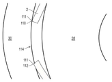
특정 구현예에서, 도 5에 나타낸 바와 같이, 적어도 하나의 파형 구조 또는 파형 구조 부위(130)는, 제1 측벽 세그먼트(22)와 접촉하고 제2 측벽 세그먼트(24)와 접촉하기 전에 종료되도록 공차 링(2) 상에 위치할 수 있다. 이 관점에서, 적어도 하나의 파형 구조 또는 파형 구조 부위(130)는 오직 하나의 측벽 세그먼트(6) 상에 배치될 수 있다. 다른 구현예에서, 적어도 하나의 파형 구조 또는 파형 구조 부위(130')는 인접하는 측벽 세그먼트(22 및 24) 사이에서 연장될 수 있다. 이러한 방식으로, 상기 하나의 파형 구조 또는 파형 구조 부위(130')는 인접한 측벽 세그먼트(22 및 24) 사이에 형성된 교차점을 쪼갤 수 있고, 각각의 인접한 측벽 세그먼트(22 및 24) 중 적어도 일부를 따라 연장될 수 있다. 추가 구현예에서, 다수의 파형 구조 또는 파형 구조 부위(130)는 인접한 측벽 세그먼트(22 및 24) 사이의 교차점을 쪼갤 수 있다. In certain embodiments, as shown in FIG. 5, at least one corrugated structure or
예를 들어, 도 6에 나타낸 바와 같은 또 다른 구현예에서, 적어도 하나의 파형 구조 또는 파형 구조 부위(130')는, 측벽 세그먼트(6) 또는 측벽(104)의 높이에 실질적으로 평행하거나 공차 링(2)의 길이(L)에 실질적으로 수직하게 배향된 라인을 따라 연장될 수 있다. 특정 구현예에서, 파형 구조 또는 파형 구조 부위(130')의 길이(LWS)(도 6의 18에 나타냄)는, 측벽 세그먼트의 높이(HSS)(도 6의 16에 나타냄)보다 작을 수 있다. 예를 들어, LWS는 0.99 HSS 이하, 예컨대 0.95 HSS 이하, 0.90 HSS 이하, 0.85 HSS 이하, 0.75 HSS 이하, 또는 심지어 0.50 HSS 이하일 수 있다. 또한 LWS는 0.1 HSS 이상, 예컨대 0.25 HSS 이상, 또는 심지어 0.45 HSS 이상일 수 있다.For example, in another embodiment as shown in FIG. 6, at least one corrugated structure or
특정 구현예에서, 파형 구조 또는 파형 구조 부위(130, 130')는 모두 서로에 대해 상이한 방향으로 배향될 수 있다. 예를 들어, 도 6에 나타낸 바와 같이, 중심 파형 구조 부위(130)는 측벽 세그먼트(6)의 높이(16)에 수직인 방향으로 연장될 수 있는 반면, 하나 이상의 외측 파형 구조(130')는 측벽 세그먼트(6)의 높이(16)에 평행한 방향으로 연장될 수 있다. 또한, 본 개시의 범주는 이 예시적인 구현예에 의해 제한되고자 의도된 것은 아니라는 점을 이해해야 한다. 파형 구조 또는 파형 구조 부위(130')는, 본원에 설명된 다양한 치수, 특징, 배향, 및 특성을 갖는 다양한 배열과 구성으로 각각의 측벽 세그먼트(6) 또는 측벽(104) 상에 배열될 수 있음을 당업자는 이해할 것이다.In certain implementations, the corrugated structure or
도 7a 및 도 7b를 이제 참조하면, 특정 구현예에서, 적어도 하나의 파형 구조 또는 파형 구조 부위(130) 중 적어도 일부는 단면에서 보는 경우(도 7a) 아치형 윤곽선을 가질 수 있다. 다른 구현예에서, 적어도 하나의 파형 구조 또는 파형 구조 부위(130') 중 적어도 일부는 단면에서 보는 경우(도 7b) 다각형 윤곽선을 가질 수 있다. 다각형 윤곽선은, 예를 들어 삼각형 윤곽선, 사변형 윤곽선(도 7b의 중심 파형 구조 또는 파형 구조 부위(130')로 나타냄), 오각형 윤곽선, 육각형 윤곽선, 칠각형 윤곽선, 또는 심지어 팔각형 윤곽선을 포함할 수 있다. 도 7b에 나타낸 바와 같이, 특정 구현예에서, 각각의 측벽 세그먼트(6) 상에 배치된 파형 구조 또는 파형 구조 부위(130, 130')는 단면에서 보는 경우 상이하거나 독특한 윤곽선을 가질 수 있다. 또한, 각각의 파형 구조 또는 파형 구조 부위(130. 130')는 아치형 윤곽 부분과 다각형 윤곽 부분을 가질 수 있다. 이러한 방식으로, 파형 구조 또는 파형 구조 부위(130')는 특정 구현예에 따라 다양할 수 있고 변경될 수 있다. 전술한 바와 같이, 파형 구조 또는 파형 구조 부위(130, 130')는 뾰족한 정점(131)을 가질 수 있다. Referring now to FIGS. 7A and 7B, in certain implementations, at least some of the at least one corrugated structure or
조립 중과 조립 후에, 파형 구조 또는 파형 구조 부위(130) 중 적어도 하나는 변형의 탄성 구역에서 작동할 수 있고, 즉 파형 구조 또는 파형 구조 부위(130) 중 적어도 하나는 힘이 인가될 시 변형할 수 있고 힘이 제거된 이후 원래 형상으로 복귀할 수 있다. 추가 구현예에서, 파형 구조 또는 파형 구조 부위(130) 중 적어도 하나는 변형의 소성 구역에서 작동할 수 있고, 즉 파형 구조 또는 파형 구조 부위(130) 중 적어도 하나는 힘이 제거된 이후 원래 형상으로 완전히 복귀할 수 없다. 다른 변형 특성의 파형 구조(130)를 단일 측벽 세그먼트(6) 또는 측벽(104) 상에 포함함으로써, 공차 링(2)의 특성, 예를 들어 강성, 활주 능력, 또는 공차 흡수를 추가로 또 변경하는 것이 가능할 수 있다.During assembly and after assembly, at least one of the corrugated structures or
본원에 설명된 구현예중 하나 이상에 따른 공차 링(2)은, 파형 구조 또는 파형 구조 부위(130)가 없는 동일한 공차 링(2)보다 적어도 1% 클 수 있는, 예컨대 파형 구조 또는 파형 구조 부위(130)가 없는 동일한 공차 링(2)보다 적어도 5% 클 수 있는, 파형 구조 또는 파형 구조 부위(130)가 없는 동일한 공차 링(2) 보다 적어도 10% 클 수 있는, 또는 파형 구조 또는 파형 구조 부위(130)가 없는 동일한 공차 링(2)과 비교해서 심지어 적어도 20%인 파형 구조 또는 파형 구조 부위(130)일 수 있는 측벽 세그먼트(6) 강성(부하시 변형에 저항하는 측벽 세그먼트의 표시자)을 갖는 좌굴 부위(35)를 가질 수 있다. 이 관점에서, 본원의 구현예에 따른 공차 링(2)이, 실질적으로 공차 링(2)의 강도 또는 슬립 특성을 변경하지 않고서, 내부 및 외부 부재 사이에서 큰 반경 방향 갭(105)을 걸치는 것이 가능할 수 있다. 본원에 사용되는 바와 같이, "걸친다"는 공차 링(2)과 내부 및 외부 부재 사이에 접촉하는 것을 지칭한다. 보다 구체적으로, "걸친다"는 내부 및 외부 부재 사이에 힘을 전달시킬 수 있는 접촉 정도를 지칭할 수 있다.The
추가 구현예에서, 공차 링(2)은 측벽(104) 일부를 통해 연장하는 적어도 하나의 애퍼처를 추가로 정의할 수 있다. 애퍼처는, 측벽(104)을 따라, 이의 미변형된 부분(119) 또는 좌굴 부위(35)를 따라, 파형 구조 또는 파형 구조 부위(130) 중 하나 이상을 따라, 또는 이들의 조합을 따라 배치될 수 있다. 이 관점에서, 측벽 세그먼트 강성은 특정 응용을 위해 추가 변경되고 조정될 수 있다. 예를 들어, 중심 애퍼처를 갖는 측벽 세그먼트(6)는 낮은 강성을 가질 수 있어서, 측벽 세그먼트(6)가 공차를 흡수하기 위해 굽히고 부하 상태시 휘게 한다.In a further embodiment, the
일 구현예에서, 내부 부재(28) 직경이 30 mm 미만일 수 있는 경우에 공차 링(2)은, 내부 부재 직경의 적어도 1%, 예컨대 직경의 적어도 5%, 직경의 적어도 10%, 또는 심지어 직경의 적어도 25%의 반경 방향 거리를 갖는 반경 방향 갭(105)에 걸칠 수 있다. 본원에 사용된 바와 같이, "반경 방향 거리"는 동심축을 갖는 내부 및 외부 부재 사이의 최단 거리를 지칭한다. 다른 구현예에서, 내부 부재(28) 직경이 적어도 30 mm일 수 있는 경우에 공차 링(2)은, 적어도 0.5 mm, 예컨대 적어도 1 mm, 적어도 1.5 mm, 적어도 3 mm, 적어도 4 mm, 적어도 5 mm, 또는 심지어 적어도 10 mm의 반경 방향 거리를 갖는 반경 방향 갭(105)에 걸칠 수 있다. 추가 구현예에서, 공차 링(2)은 250 mm 이하, 예컨대 200 mm 이하, 100 mm 이하, 또는 심지어 50 mm 이하의 반경 방향 거리를 갖는 반경 방향 갭(105)에 걸칠 수 있다.In one embodiment, the
본원에 설명된 일 구현예에 따라, 공차 링(2)은 좌굴 부위(35)의 버클링으로부터 형성된 복수의 측벽 세그먼트(6)를 가질 수 있다. 각각의 측벽 세그먼트(6)는, 내부 부재(28)와 접촉하는 적어도 하나의 지점을 형성하기 위해 내부 부재(28)의 외측 표면(210)과 접촉할 수 있다. 보다 특정적인 구현예에서, 공차 링(2)과 내부 부재(28) 사이의 접촉 지점은, 각각의 측벽 세그먼트(6)의 중간 부분(214)에서 생길 수 있다. 특정 구현예에서, 내부 부재(28), 및 측벽 세그먼트(6) 각각의 중간 부분(214) 사이에서의 접촉 지점은 점 또는 선 접촉, 예를 들어 단일 지점 또는 단일 선을 따라 형성된 접촉부일 수 있다. 대안적으로, 접촉 지점은 면 접촉, 예를 들어 측벽 세그먼트(6) 각각의 길이 및 높이 모두에 평행한 방향에서 측정된 면적에 형성된 접촉부일 수 있다.According to one embodiment described herein, the
추가 구현예에서, 좌굴 부위(35)의 측벽 세그먼트(6) 각각은, 외부 부재(30)와 접촉하는 적어도 하나의 지점을 형성하기 위해, 외부 부재(30)의 내측 표면(212)과 접촉할 수 있다. 보다 특정적인 구현예에서, 공차 링(2)과 외부 부재(30) 사이의 접촉 지점은, 각각의 측벽 세그먼트(6)에서의 좌굴 부위(35)의 대향하는 정점(7, 7')에서 생길 수 있다. 이 관점에서, 측벽 세그먼트(6) 각각은 내부 및 외부 부재(28 및 30) 사이에 세 개의 접촉 지점-정점(7, 7')에서의 지지 접촉 지점 두 개, 및 중간 부분(214)에서의 부하 접촉 지점 한 개를 형성하는 것이 가능할 수 있다.In a further embodiment, each of the
반경 방향 갭(105)은, 내부 부재(28)의 외측 표면(210)에 의해 정의되는 내부 반경(IR), 및 외부 부재(30)의 내측 표면(212)에 의해 정의되는 외부 반경(OR)을 정의할 수 있다. 반경 방향 갭(105)은, OR과 IR 사이의 차이로 측정되는 반경 방향 두께(TAG)를 가질 수 있다. 반경 방향 갭 종횡비는 IR/OR의 비로 정의될 수 있다.The
다수의 구현예에서, 일부 설계 특징부가 공차 링(2)에 포함되어 어셈블리(1)의 설치 및 사용 중에 좌굴 부위(35)의 버클링을 개선시킬 수 있다. 다수의 구현예에서, 파형 구조 정점(131)은, 공차 링(2), 및 어셈블리의 내부 구성 요소(2)와 외부 구성 요소(30) 중 적어도 하나 사이에 추가적으로 인터로크를 촉진하도록 뾰족할 수 있다. 다수의 구현예에서, 공차 링(2)의 내부 반경(IRTR)은, 미설치 상태에서 내부 부재(28)의 외부 표면(210)에 의해 정의된 내부 반경(IR)보다 더 크도록 제조될 수 있다. 이 방식으로, 어셈블리(1)의 설치 중에 간섭 끼워맞춤을 제공하도록 공차 링(2) 위에 외부 부재(30)를 가압시킬 수 있을 시, 설치 중에 좌굴 부위(35)의 버클링은 장려될 수 있다. 다수의 구현예에서, 좌굴 범위(35)와 파형 구조 부위(130)는 상이한 재료로 만들어질 수 있거나 상기 나열한 재료와 상이한 재료 성분을 가질 수 있어서, 좌굴 부위(35)의 버클링은 어셈블리(1) 내에 설치 또는 사용 중에 장려될 수 있다.In many implementations, some design features are included in the
다수의 구현예에서, 적어도 하나의 중간 부위(119) (또는 좌굴 부위(35))는, 공차 링(2) 중 적어도 하나의 비좌굴 부위(파형 구조 부위(130))의 반경과 상이할 수 있는 반경을 가질 수 있다. 다수의 구현예에서, 어셈블리 내에 설치 또는 사용 중에 좌굴 부위(35)의 버클링을 촉진하기 위해, 공차 링(2)의 내부 반경(IRTR)은 그 원주를 따라 개조될 수 있다. 예를 들어, 좌굴 부위(35)의 내부 반경(IRTRBR)은 공차 링(2)의 원주를 따라 파형 구조 부위(130)의 반경(IRTRWS)보다 크기가 작을 수 있다. 대안적으로, 좌굴 부위(35)의 내부 반경(IRTRBR)은 공차 링(2)의 원주를 따라 파형 구조 부위(130)의 반경(IRTRWS)보다 크기가 클 수 있다. 다수의 구현예에서, 공차 링(2)의 일부(예컨대 파형 구조 부위(130))는 공차 링(2)의 다른 부분(예컨대 좌굴 부위(35))보다 상이한 곡률 반경을 가질 수 있다. 다수의 구현예에서, 파형 구조 부위(130) 또는 좌굴 부위(35) 중 적어도 하나는, 내부 부재(28)의 외측 표면(210)에 의해 정의된 내부 반경(IR)과 유사할 수 있는 곡률 반경을 가질 수 있다. 예를 들어, 파형 구조 부위(130) 또는 좌굴 부위(35) 중 적어도 하나의 곡률 반경은, 내부 부재(28)의 외측 표면(210)에 의해 정의된 내부 반경(IR)의 10% 내에, 예컨대 5% 내에, 4% 내에, 또는 심지어 3% 내일 수 있다. 보다 구체적인 구현예에서, 파형 구조 부위(130)는 공차 링(2)의 전체 내부 반경(IRTR)보다 더 작은 곡률 반경을 가질 수 있다. 다수의 구현예에서, 좌굴 부위(35)의 호 길이(ALBR)는 공차 링(2)의 원주를 따라 파형 구조 부위(130)의 호 길이(ALWS)보다 크기가 작을 수 있다. 대안적으로, 좌굴 부위(35)의 호 길이(ALBR)는 공차 링(2)의 원주를 따라 파형 구조 부위(130)의 호 길이(ALWS)보다 크기가 클 수 있다. 어셈블리(1) 내에 설치 또는 사용 중에 공차 링(2) 상의 좌굴 부위(35)의 버클링을 촉진하기 위해, 설계 특징부 임의의 것이 사용될 수 있다.In many embodiments, the at least one intermediate region 119 (or buckling region 35) can be different from the radius of at least one non-buckling region (waveform structural region 130) of the
당업자는 전체 본 명세서를 읽은 후, 반경 방향 갭(108)에 걸치기 위해 필요한 측벽 세그먼트(6)의 수는, 몇몇 변수, 예컨대 반경 방향 갭 종횡비, 측벽 세그먼트(6)의 두께(Tss 및 Tws), 및 원하는 부하력, 예를 들어 슬립 특성, 허용된 반경 방향 최대 및 최소력, 과 측벽 세그먼트(6)의 허용 가능한 굽힘 조건에 기초하여 변할 수 있다. 이 관점에서, 특정 반경 방향 갭 종횡비에 있어서 측벽 세그먼트(6)의 수를 결정하는 제1 단계는, 다음의 식을 이용하여 측벽 세그먼트의 이론적 갯수를 계산하는 단계를 포함할 수 있다:After the person skilled in the art has read the entire specification, the number of

여기서, n은 좌굴 부위(35)로부터 형성된 측벽 세그먼트(6)의 이론적 갯수로, 공차 링(2)이 완벽하게 또는 거의 완벽하게 반경 방향 갭(105)에 끼워맞춤되는 데 필요한 것이고, IR/OR는 반경 방향 갭 종횡비이다. 식 1을 사용하여, 미부하 또는 미굽힘 공차 링 구성(예컨대 도 5에 나타냄)에서 측벽 세그먼트(6)의 적당한 갯수를 결정하는 것이 가능할 수 있다. 예를 들어, 식(1)을 사용하여 직경이 16 mm인 천공(204)을 갖는 외부 부재(30) 내에 배치된 직경 8 mm의 내부 부재(28)는, 공차 링(2)의 임의 부분을 변형하지 않고서 3개의 측벽 세그먼트(6) (또는 좌굴 부위(35))를 갖는 공차 링에 완벽하게 또는 거의 완벽하게 끼워맞춤될 수 있다. 유사하게, 직경이 14.142 mm인 천공(204)을 갖는 외부 부재(30) 내에 배치된 직경 10 mm의 내부 부재(28)는, 공차 링(2)의 임의 부분을 변형하지 않고서 4개의 측벽 세그먼트(6) (또는 좌굴 부위(35))를 갖는 공차 링에 완벽하게 또는 거의 완벽하게 끼워맞춤될 수 있다. 본원에 사용되는 바와 같이, "완벽하게 끼워맞춤"은 두 객체 사이의 크기 비율이 1:1인 것을 지칭한다. 보다 구체적으로, 본원에 사용되는 바와 같이, "완벽하게 끼워맞춤"은 TAG에 대한 공차 링의 효과적인 반경 방향 두께 RTE의 1:1 비율을 지칭할 수 있다. 즉, 완벽하게 끼워 맞춘 공차 링은, 공차 링이 휨 또는 부하력을 나타내지 않고서 내부 부재와 외부 부재 사이에 배치될 수 있는 한편, 각각의 측벽 세그먼트는 동시에 내부 및 외부 부재와 세 개의 접촉 지점-외부 부재와의 두 개의 접촉 지점과 내부 부재와의 한 개 접촉 지점을 형성할 수 있다. 본원에 사용되는 바와 같이, "거의 완벽하게 끼워맞춤"은 효과적인 반경 방향 두께와 TAG 사이의 1:1 비율로부터 5% 미만 정도, 예컨대 4% 미만 정도, 3% 미만 정도, 2% 미만 정도, 또는 심지어 1% 미만 정도의 편차를 지칭한다. 당업자는 식(1)이 측벽 세그먼트(6)의 두께를 설명하도록 조정될 수 있음을 이해할 것이다.Here, n is the theoretical number of
n이 자연수가 아닌 응용에서, 예를 들어 직경 26 mm인 천공(204)을 갖는 외부 부재(30) 내에 배치된 직경 20 mm의 내부 부재(28)가 4.533개의 측벽 세그먼트(6)를 갖는 공차 링의 사용을 요구하는 경우, 몇몇 방식 중 하나로 공차 링(2)을 조정할 필요가 있을 수 있다.In applications where n is not a natural number, an
마지막 예에서 요구된 측벽 세그먼트(6)의 갯수는 4.0과 5.0 사이이기 때문에, 응용에 따라 4개 또는 5개 측벽 세그먼트를 갖는 공차 링을 사용하는 것이 허용 가능할 수 있다. 측벽 세그먼트의 가장 가까운 자연수, 예를 들어 4 또는 5개의 등변 측벽 세그먼트로 어림잡음으로써, 비균형적인 반경 방향 부하는 피할 수 있다. 특정 구현예에서, 측벽 세그먼트의 갯수가 낮을수록 사용하는 것이 유리할 수 있고, 이에 의해 축 방향 갭의 원주 크기를 증가시킨다.Since the number of
미부하의, 예를 들어 미변형된 공차 링에 필요한 측벽 세그먼트(6)의 갯수는 식(1)을 사용하여 결정된 후, 공차 링(2)의 측벽 세그먼트(6), 파형 구조(130), 및 다른 특징부의 갯수, 형상, 및 크기를 조정함으로써, 반경 방향 강성, 슬립 특성, 부하 상태, 및 다른 응용 특정 변경이 공차 링(2)에 만들어질 수 있다. 예를 들어, 비제한적인 구현예에서, √2의 반경 방향 갭 종횡비를 갖는 반경 방향 갭(105)은, 부하 특성 없이 4개의 측벽 세그먼트(6)를 갖는 공차 링(2), 예를 들어 사변형 공차 링에 완벽하게 끼워맞춤될 수 있다. 상기 반경 방향 갭 내에 3개의 측벽 세그먼트(6)를 갖는 공차 링(2)을 배치하면, 내부 부재, 공차 링, 및 외부 부재 사이의 반경 방향 부하를 허용할 수 있고, 이에 의해 어셈블리의 특성을 변화시킨다.The number of
유사하게, 다른 비제한적인 구현예에서, 약 1.2361인 반경 방향 갭 종횡비를 갖는 반경 방향 갭(105)은, 부하 특성 없이 5개의 측벽 세그먼트(6)를 갖는 공차 링(2), 예를 들어 오각형 공차 링에 거의 완벽하게 끼워맞춤될 수 있다. 상기 오각형 공차 링에 인접한 측벽 세그먼트(6) 각각 사이에 부분적인 측벽 세그먼트(120)를 배치하면, 내부 부재, 공차 링, 및 외부 부재 사이의 반경 방향 부하를 허용할 수 있고, 이에 의해 어셈블리의 특성을 변화시킨다.Similarly, in another non-limiting embodiment, the
일 구현예에서, 어셈블리(1)는 샤프트(4) 또는 하우징(8)에 대해 길이 방향으로 적어도 1 kgf의 조립력, 예를 들어 적어도 2 kgf, 적어도 3 kgf, 적어도 4 kgf, 적어도 5 kgf, 적어도 10 kgf 또는 심지어 적어도 15 kgf의 조립력에 의해 설치되거나 조립될 수 있다. 또 다른 구현예에서, 토크 어셈블리(1)는 하우징(8)에 대해 길이 방향으로 200 kgf 이하의 조립력, 예를 들어 150 kgf 이하, 100 kgf 이하, 75 kgf 이하, 또는 심지어 25 kgf 이하의 조립력에 의해 설치되거나 조립될 수 있다.In one embodiment, the assembly 1 has an assembly force of at least 1 kgf in the longitudinal direction relative to the
일 구현예에서, 어셈블리(1)는, 공차 링(2)의 수명에 걸쳐 공칭상 +/- 10% 변화를 갖고 약 1Nㆍm 내지 약 20 Nㆍm의 요구 토크값을 제공하도록 쪼여질 수 있다.In one embodiment, the assembly 1 can be split to provide a required torque value from about 1 N · m to about 20 N · m with a nominal +/− 10% change over the life of the
공차 링(2) 또는 어셈블리(1)를 사용하면, 차량 테일 게이트, 도어 프레임, 시트 어셈블리, 또는 다른 유형의 응용과 같으나 이에 제한되지 않는 몇몇 응용 분야에 증가된 장점을 제공할 수 있다. 주목할 만한 것으로, 공차 링을 사용하면, 공차 링(2)의 수명에 걸쳐 공칭상 +/- 10% 변화의 일관성 있는 토크를 제공하는 과부하 방지 장치를 제공할 수 있다. 본원에 기술된 이유와 특징부를 통해, 이는, 시간에 걸쳐 대폭 변하지 않는 소정의 토크값에서 어셈블리 내에 적당한 슬립을 제공할 수 있다. 공차 링(2)은 10 사이클 이하의 사이클로 어셈블리(1) 내에서 작동할 수 있다. The use of a
다수의 상이한 양태 및 구현예가 가능하다. 이들 양태 및 구현예의 일부가 아래에 설명된다. 이 명세서를 읽은 후, 당업자는 이들 양태 및 구현예가 단지 예시적인 것이며 본 발명의 범주를 제한하지 않음을 이해할 것이다. 구현예는 이하에 열거된 구현예 중 하나 이상의 임의의 구현예에 따른 것일 수 있다.Many different aspects and implementations are possible. Some of these aspects and implementations are described below. After reading this specification, those skilled in the art will understand that these aspects and implementations are illustrative only and do not limit the scope of the invention. Implementations may be in accordance with any one or more of the implementations listed below.
구현예 1. 외부 부재; 내부 부재; 및 상기 내부 부재와 상기 외부 부재 사이에 배치된 공차 링을 포함하는 어셈블리로서, 상기 공차 링은 대향하는 에지를 포함한 분리 링을 포함하고, 상기 에지는 상기 내부 부재 또는 상기 외부 부재 중 하나와 체결하여 상기 공차 링, 및 상기 내부 부재 또는 상기 외부 부재 중 적어도 하나 사이의 상대적 이동을 방지하거나 제한하는, 어셈블리.Embodiment 1. External member; Internal member; And an tolerance ring disposed between the inner member and the outer member, wherein the tolerance ring includes a separating ring including opposing edges, the edge engaging with either the inner member or the outer member An assembly that prevents or limits relative movement between the tolerance ring and at least one of the inner member or the outer member.
구현예 2. 외부 부재; 내부 부재; 및 상기 내부 부재와 상기 외부 부재 사이에 배치된 공차 링을 포함하는 어셈블리로서, 상기 공차 링은, 상기 내부 부재와 상기 외부 부재 사이에 설치될 시 변형되고 상기 내부 부재와 상기 외부 부재 사이의 간섭 끼워맞춤으로 인해 상기 공차 링에 적어도 하나의 좌굴 부위를 형성하고, 미설치 상태에서 상기 좌굴 부위는 없는, 어셈블리.
구현예 3. 구현예 1에 있어서, 상기 에지는, 상기 내부 부재 또는 상기 외부 부재 중 적어도 하나와 접촉하는 상기 에지 중 적어도 하나의 코너에 의해 초래되는 인터로크를 형성하는, 어셈블리.Embodiment 3 The assembly of Embodiment 1, wherein the edge forms an interlock caused by a corner of at least one of the edges contacting at least one of the inner member or the outer member.
구현예 4. 구현예 1 내지 구현예 3에 있어서, 상기 에지는 상기 내부 부재와 체결되는, 어셈블리.
구현예 5. 구현예 1, 구현예 3 및 구현예 4 중 어느 한 예에 있어서, 상기 에지는 상기 외부 부재와 체결되는, 어셈블리.Embodiment 5 The assembly of any one of Embodiment 1, Embodiment 3, and
구현예 6. 구현예 2에 있어서, 상기 좌굴 부위는 적어도 부분적으로 탄성 형성되어, 분리시 상기 좌굴 부위가 적어도 부분적으로 붕괴되는, 어셈블리.
구현예 7. 구현예 2 내지 구현예 6 중 어느 한 예에 있어서, 상기 좌굴 부위는 좌굴 부위 높이(HBR)를 갖되, 분리시 HBR는 적어도 50% 정도 감소되는, 어셈블리.Embodiment 7. The assembly of any one of Embodiments 2-6, wherein the buckling portion has a buckling height (H BR ), but upon separation, H BR is reduced by at least 50%.
구현예 8. 구현예 2, 구현예 6 및 구현예 7 중 어느 한 예에 있어서, 상기 좌굴 부위는 상기 외부 부재와 접촉하는, 어셈블리.
구현예 9. 구현예 2, 구현예 6 내지 구현예 8 중 어느 한 예에 있어서, 미설치 상태에서, 상기 공차 링은 상기 공차 링 주위로 원주상 이격된 복수의 파형 구조 부위, 및 상기 파형 구조 부위 사이에 배치된 복수의 중간 부위를 포함하고, 적어도 하나의 중간 부위는 설치 상태에서 상기 좌굴 부위를 형성하기 위해 조립시 변형되는, 어셈블리.Embodiment 9 The method of any one of
구현예 10. 구현예 1 내지 구현예 9 중 어느 한 예에 있어서, 상기 내부 부재 또는 상기 외부 부재 중 적어도 하나는 회전 방향, 축 방향 또는 반경 방향 이동이 가능할 수 있는, 어셈블리.
구현예 11. 구현예 10에 있어서, 저마찰층은 폴리머를 포함하는, 어셈블리.Embodiment 11. The assembly of
구현예 12. 구현예 1 내지 구현예 11 중 어느 한 예에 있어서, 상기 내부 부재 또는 상기 외부 부재 중 적어도 하나는 회전 방향, 축 방향 또는 반경 방향 이동이 가능할 수 있는, 어셈블리.Embodiment 12. The assembly of any of Embodiments 1-11, wherein at least one of the inner member or the outer member is capable of rotational, axial or radial movement.
구현예 13. 구현예 9 내지 구현예 12 중 어느 한 예에 있어서, 상기 적어도 하나의 파형 구조 부위는 둥근 정점을 갖는, 어셈블리.Embodiment 13. The assembly of any one of Embodiments 9 to 12, wherein the at least one corrugated structure portion has a rounded apex.
구현예 14. 구현예 9 내지 구현예 13 중 어느 한 예에 있어서, 상기 파형 구조 부위는 상기 공차 링의 길이에 실질적으로 수직 배향된 적어도 하나의 파형 구조를 포함하는, 어셈블리.Embodiment 14. The assembly of any one of Embodiments 9 to 13, wherein the corrugated structure portion comprises at least one corrugated structure oriented substantially perpendicular to the length of the tolerance ring.
구현예 15. 구현예 9 내지 구현예 14 중 어느 한 예에 있어서, 상기 파형 구조 부위는 상기 공차 링의 길이에 실질적으로 수평 배향된 적어도 하나의 파형 구조를 포함하는, 어셈블리.Embodiment 15. The assembly of any one of Embodiments 9 to 14, wherein the corrugated structure portion comprises at least one corrugated structure oriented substantially horizontally to the length of the tolerance ring.
구현예 16. 구현예 9 내지 구현예 15 중 어느 한 예에 있어서, 상기 중간 부위의 일부는 미설치 상태에서 윤곽을 갖는, 어셈블리.
구현예 17. 구현예 9 내지 구현예 16 중 어느 한 예에 있어서, 설치 상태에서 적어도 하나의 파형 구조 부위는 내측으로 변형하는 반면, 적어도 하나의 좌굴 부위는 외측으로 변형하는, 어셈블리. Embodiment 17. The assembly of any one of Embodiments 9 to 16, wherein at least one corrugated structure site deforms inward while the at least one buckling site deforms outward.
구현예 18. 구현예 1 내지 구현예 17 중 어느 한 예에 있어서, 적어도 하나의 좌굴 부위는, 상기 외부 구성 요소와 접촉하는 한 개의 지점을 형성하도록 조정되는, 어셈블리.
구현예 19. 구현예 1 내지 구현예 18 중 어느 한 예에 있어서, 상기 공차 링의 일부는, 상기 공차 링의 다른 부분과 상이한 곡률 반경을 갖는, 어셈블리. Embodiment 19. The assembly of any one of Embodiments 1 to 18, wherein the portion of the tolerance ring has a different radius of curvature than the other portion of the tolerance ring.
구현예 20. 구현예 9 내지 구현예 19 중 어느 한 예에 있어서, 적어도 하나의 중간 부위는, 상기 공차 링의 적어도 하나의 파형 구조의 곡률 반경과 상이한 곡률 반경을 갖는, 어셈블리.
위에 설명된 모든 특징부가 필요하지 않고, 세부적인 특징부 일부가 필요하지 않고, 설명한 것 외에 하나 이상의 특징부가 제공될 수 있다. 또한, 특징부가 기술되는 순서는 특징부가 설치된 순서일 필요는 없다.Not all of the features described above are required, some of the detailed features are not required, and one or more features other than those described can be provided. Also, the order in which features are described need not be the order in which the features are installed.
명확성을 위해 별도의 구현예 맥락에서 본원에 설명된 특정 특징부는 단일 구현예에서 조합하여 또한 제공될 수도 있다. 반대로, 간략화를 위해, 단일 구현예 맥락에서 설명된 다양한 특징부는 개별적으로 또는 임의의 서브 조합으로 또한 제공될 수도 있다.For clarity, certain features described herein in the context of separate embodiments may also be provided in combination in a single embodiment. Conversely, for simplicity, various features described in the context of a single implementation may also be provided individually or in any subcombination.
혜택, 다른 장점 및 문제점에 대한 해결책이 특정 구현예와 관련하여 상기에 설명되었다. 그러나, 어떤 혜택, 장점, 또는 해결책이 발생하거나 더 현저해질 수 있도록 하는, 혜택, 장점, 해결책 및 임의의 특징부(들)가 모든 청구범위의 결정적, 필수적 또는 본질적 특징부로 해석되어서는 안된다.Benefits, other advantages and solutions to problems have been described above with regard to specific embodiments. However, benefits, advantages, solutions and any feature (s), which allow any benefit, advantage, or solution to occur or become more prominent, should not be construed as critical, essential or essential features of all claims.
본원에 기술된 구현예의 설명 및 예시는 다양한 구현예의 구조에 대한 일반적인 이해를 제공하고자 함이다. 설명 및 예시는 본원에 설명된 구조 또는 방법을 사용하는 장치 및 시스템의 모든 요소 및 특징부를 철저하고 포괄적으로 설명하기 위한 것이 아니다. 개별적인 구현예가 단일 구현예로 조합되어 제공될 수도 있고, 반대로 간략화를 위해 단일 구현예의 맥락에서 설명된 다양한 특징부가 개별적으로 또는 임의의 하위 조합으로 제공될 수도 있다. 또한, 범위로 명시된 값에 대한 참조는 그 범위 내의 각각의 모든 값을 포함한다. 많은 다른 구현예는 본 명세서를 읽은 후에 당업자에게 명백할 수 있다. 구조적 대체, 논리적 대체, 또는 임의의 변화가 본 개시의 범주로부터 벗어나지 않고 만들어질 수 있도록, 다른 구현예는 본 개시를 사용할 수 있거나 본 개시로부터 유도될 수 있다. 따라서, 본 개시는 제한적이라기보다는 예시적인 것으로 간주되어야 한다.The descriptions and examples of the embodiments described herein are intended to provide a general understanding of the structure of various embodiments. The description and examples are not intended to exhaustively and comprehensively describe all elements and features of devices and systems using the structures or methods described herein. Individual embodiments may be provided in combination in a single embodiment, or, conversely, various features described in the context of a single embodiment may be provided individually or in any subcombination for simplicity. Also, references to values specified in ranges include each and every value within that range. Many other embodiments may be apparent to those skilled in the art after reading this specification. Other implementations may use or be derived from the present disclosure, such that structural replacements, logical replacements, or any changes can be made without departing from the scope of the present disclosure. Accordingly, the present disclosure should be considered illustrative rather than restrictive.
Claims (15)
외부 부재;
내부 부재; 및
상기 내부 부재와 상기 외부 부재 사이에 배치된 공차 링을 포함하되, 상기 공차 링은 대향하는 에지를 갖는 분리 링을 포함하고, 상기 에지는 상기 내부 부재 또는 상기 외부 부재 중 하나와 체결하여 상기 내부 부재 또는 상기 외부 부재 중 적어도 하나와 상기 공차 링 사이의 상대적 이동을 방지하거나 제한하는, 어셈블리.As an assembly,
External member;
Internal member; And
A tolerance ring disposed between the inner member and the outer member, wherein the tolerance ring comprises a separating ring having opposing edges, the edge engaging the inner member or one of the outer members to engage the inner member Or preventing or restricting relative movement between at least one of the outer members and the tolerance ring.
외부 부재;
내부 부재; 및
상기 내부 부재와 상기 외부 부재 사이에 배치된 공차 링을 포함하되, 상기 공차 링은, 상기 내부 부재와 상기 외부 부재 사이에 설치시 변형되고 상기 내부 부재와 상기 외부 부재 사이의 간섭 끼워맞춤으로 인해 상기 공차 링에 적어도 하나의 좌굴 부위를 형성하고, 미설치 상태에서 상기 좌굴 부위는 없는, 어셈블리.As an assembly,
External member;
Internal member; And
A tolerance ring disposed between the inner member and the outer member, the tolerance ring being deformed upon installation between the inner member and the outer member and due to interference fit between the inner member and the outer member An assembly that forms at least one buckling portion in a tolerance ring, wherein the buckling portion is absent in an uninstalled state.
Applications Claiming Priority (3)
| Application Number | Priority Date | Filing Date | Title |
|---|---|---|---|
| US201762565368P | 2017-09-29 | 2017-09-29 | |
| US62/565,368 | 2017-09-29 | ||
| PCT/EP2018/076385 WO2019063752A2 (en) | 2017-09-29 | 2018-09-28 | Tolerance ring |
Publications (2)
| Publication Number | Publication Date |
|---|---|
| KR20200057772A true KR20200057772A (en) | 2020-05-26 |
| KR102468427B1 KR102468427B1 (en) | 2022-11-22 |
Family
ID=63832374
Family Applications (1)
| Application Number | Title | Priority Date | Filing Date |
|---|---|---|---|
| KR1020207012561A KR102468427B1 (en) | 2017-09-29 | 2018-09-28 | tolerance ring |
Country Status (6)
| Country | Link |
|---|---|
| US (2) | US11499591B2 (en) |
| EP (1) | EP3688330A2 (en) |
| JP (2) | JP6964188B2 (en) |
| KR (1) | KR102468427B1 (en) |
| CN (1) | CN111279090B (en) |
| WO (1) | WO2019063752A2 (en) |
Cited By (1)
| Publication number | Priority date | Publication date | Assignee | Title |
|---|---|---|---|---|
| KR20240047294A (en) | 2022-10-04 | 2024-04-12 | 오영식 | Method, apparatus, and system for improving the resolution of pictures taken multiple times by a moving camera |
Families Citing this family (3)
| Publication number | Priority date | Publication date | Assignee | Title |
|---|---|---|---|---|
| WO2019063752A2 (en) | 2017-09-29 | 2019-04-04 | Saint-Gobain Performance Plastics Rencol Limited | Tolerance ring |
| JP7266088B2 (en) * | 2018-07-17 | 2023-04-27 | サン-ゴバン パフォーマンス プラスティックス レンコール リミティド | Tolerance rings and assemblies with tolerance rings |
| US20230213051A1 (en) * | 2021-12-30 | 2023-07-06 | Saint-Gobain Performance Plastics Rencol Limited | Tolerance ring with modified surface properties |
Citations (7)
| Publication number | Priority date | Publication date | Assignee | Title |
|---|---|---|---|---|
| US4222246A (en) * | 1978-12-11 | 1980-09-16 | Roller Bearing Company Of America | Slip clutch |
| US4250927A (en) * | 1979-08-24 | 1981-02-17 | Piper Aircraft Corporation | Duct spacer clip and duct assembly |
| EP0234398A2 (en) * | 1986-02-26 | 1987-09-02 | Etablissement Supervis | Cam shaft for actuating the valve tappets in internal combustion machines |
| EP1106474A2 (en) * | 1999-12-07 | 2001-06-13 | Koyo Seiko Co., Ltd. | Electric steering apparatus |
| KR20120065415A (en) * | 2009-09-25 | 2012-06-20 | 생-고뱅 퍼포먼스 플라스틱스 렌콜 리미티드 | Apparatus for tolerance ring control of slip interface sliding forces |
| WO2013095495A1 (en) * | 2011-12-22 | 2013-06-27 | Seagate Technology Llc | Collapsible tolerance rings with weak points |
| US20140362474A1 (en) * | 2011-12-09 | 2014-12-11 | Nhk Spring Co., Ltd. | Tolerance ring, hard disk device, and method for manufacturing hard disk device |
Family Cites Families (45)
| Publication number | Priority date | Publication date | Assignee | Title |
|---|---|---|---|---|
| US1662544A (en) * | 1926-03-01 | 1928-03-13 | Simplex Piston Ring Company | Piston ring |
| US1773250A (en) * | 1929-02-04 | 1930-08-19 | Smalley Accessories Corp | Piston ring |
| US2117986A (en) * | 1935-03-11 | 1938-05-17 | Wilkening Mfg Co | Piston ring construction |
| US2170970A (en) * | 1937-05-15 | 1939-08-29 | Charles F Johnston | Piston, ring, and ring expander |
| US2886354A (en) * | 1950-02-02 | 1959-05-12 | Bjorklund Gustaf Erik | Fasteners |
| US2657082A (en) * | 1950-04-06 | 1953-10-27 | Veeder Root Inc | Keying device |
| DE834477C (en) * | 1950-05-11 | 1952-03-20 | Star Kugelhalter Ges M B H Deu | Method and means for the storage of round or bored machine parts of any seat type |
| US3097871A (en) * | 1961-07-05 | 1963-07-16 | Mcnally Bros Machine & Gear Co | Coupling device |
| US3348887A (en) * | 1965-03-04 | 1967-10-24 | Black & Decker Mfg Co | Combination tolerance ring and bearing journal member |
| US3319484A (en) * | 1965-07-21 | 1967-05-16 | Clarostat Mfg Co Inc | Means for coupling shaft and bushing |
| US3586290A (en) * | 1969-06-25 | 1971-06-22 | Garrett Corp | Valve |
| DE2018367B1 (en) * | 1970-04-16 | 1971-07-29 | Deutsche Star Kugelhalter Gmbh, 8720 Schweinfurt | Connection element for a coupling with clamping sleeve for fastening a hub on a shaft |
| US3967829A (en) * | 1973-03-09 | 1976-07-06 | Rogers-Dierks, Inc. | Seal ring |
| GB1546152A (en) * | 1976-10-16 | 1979-05-16 | Cross Mfg Co | Couplings |
| US4136982A (en) * | 1977-10-04 | 1979-01-30 | General Motors Corporation | Centered fastener assembly |
| US4286894A (en) * | 1979-03-21 | 1981-09-01 | Roller Bearing Company Of America | Tolerance rings |
| DE3314909C2 (en) * | 1983-04-25 | 1994-11-24 | Rockinger Spezial Fab Joh | Fastening assembly for a trailer hitch and method for its assembly |
| US4981390A (en) * | 1987-03-06 | 1991-01-01 | The Ray Engineering Co., Ltd. | Tolerance ring with retaining means |
| US4790683A (en) * | 1987-10-05 | 1988-12-13 | Cramer Jr Arthur A | Tolerance ring and shim and method of use |
| US5473140A (en) * | 1994-03-14 | 1995-12-05 | Miller Electric Mfg. Co. | Welding nozzle retaining ring |
| JP2002505396A (en) | 1998-02-27 | 2002-02-19 | アリスン・エンジン・カンパニー・インコーポレーテッド | Method and apparatus for mounting bearing |
| GB2373916B (en) * | 1999-12-03 | 2004-05-05 | Seagate Technology Llc | Tolerance ring with low consistent installation force profile |
| US6889956B2 (en) * | 2002-08-16 | 2005-05-10 | Delphi Technologies, Inc. | Poppet valve bushing with tolerance ring |
| US8087977B2 (en) * | 2005-05-13 | 2012-01-03 | Black & Decker Inc. | Angle grinder |
| US7611303B2 (en) * | 2005-06-01 | 2009-11-03 | Intri-Plex Technologies, Inc. | Tolerance ring with high axial static friction |
| US7554771B2 (en) * | 2006-09-11 | 2009-06-30 | Intri-Plex Technologies, Inc. | Tolerance ring for data storage with overlapping tab feature for mass control |
| US8342307B2 (en) * | 2006-12-22 | 2013-01-01 | Sulzer Euroflamm Germany Gmbh | Synchronizing ring |
| WO2010029429A1 (en) | 2008-09-10 | 2010-03-18 | Saint-Gobain Performance Plastics Rencol Limited | Tolerance ring and mounting assembly with such a tolerance ring |
| JP5474710B2 (en) * | 2010-09-03 | 2014-04-16 | 株式会社東郷製作所 | Torque transmission tolerance ring |
| US9019663B2 (en) * | 2011-12-28 | 2015-04-28 | Nhk Spring Co., Ltd. | Tolerance ring |
| US9028165B2 (en) | 2012-04-30 | 2015-05-12 | Saint-Gobain Performance Plastics Rencol Limited | Tolerance ring with perforated waves |
| US9062700B2 (en) | 2012-06-29 | 2015-06-23 | Saint-Gobain Performance Plastics Rencol Limited | Tolerance ring with component engagement structures |
| CN104350299A (en) * | 2012-06-29 | 2015-02-11 | 圣戈班性能塑料万科有限公司 | Multipiece tolerance ring |
| KR101699993B1 (en) * | 2012-10-05 | 2017-01-25 | 주식회사 만도 | The pulley structure of the belt type electric power steering gear |
| US9222521B2 (en) * | 2012-12-16 | 2015-12-29 | Saint-Gobain Performance Plastics Rencol Limited | Torque limiting tolerance ring |
| DE102013208476A1 (en) | 2013-05-08 | 2014-11-13 | Ksb Aktiengesellschaft | pump assembly |
| US10094426B2 (en) * | 2013-06-27 | 2018-10-09 | Saint-Gobain Performance Plastics Rencol Limited | Tolerance ring with divided torque slip |
| US10125854B2 (en) * | 2013-09-20 | 2018-11-13 | Bair-Ling Technologies, LLC | Torque limiting system |
| WO2015080276A1 (en) | 2013-11-29 | 2015-06-04 | 日本発條株式会社 | Tolerance ring and hard disk device |
| EP3152451B1 (en) * | 2014-06-06 | 2019-03-06 | Saint-Gobain Performance Plastics Rencol Limited | Tolerance ring |
| CN204419897U (en) * | 2014-09-23 | 2015-06-24 | 美国圣戈班性能塑料公司 | The reeded assembly of tool |
| EP3048320B1 (en) * | 2015-01-22 | 2017-09-06 | Ansaldo Energia Switzerland AG | Centering arrangement of two parts relative to each other |
| JP6605253B2 (en) * | 2015-08-07 | 2019-11-13 | 株式会社東郷製作所 | Tolerance ring |
| JP6523861B2 (en) * | 2015-08-07 | 2019-06-05 | 株式会社東郷製作所 | Shaft coupling structure |
| WO2019063752A2 (en) | 2017-09-29 | 2019-04-04 | Saint-Gobain Performance Plastics Rencol Limited | Tolerance ring |
-
2018
- 2018-09-28 WO PCT/EP2018/076385 patent/WO2019063752A2/en unknown
- 2018-09-28 CN CN201880063783.4A patent/CN111279090B/en active Active
- 2018-09-28 US US16/145,270 patent/US11499591B2/en active Active
- 2018-09-28 KR KR1020207012561A patent/KR102468427B1/en active IP Right Grant
- 2018-09-28 EP EP18785278.5A patent/EP3688330A2/en active Pending
- 2018-09-28 JP JP2020518061A patent/JP6964188B2/en active Active
-
2021
- 2021-10-18 JP JP2021170439A patent/JP7439033B2/en active Active
-
2022
- 2022-10-07 US US17/938,734 patent/US11859670B2/en active Active
Patent Citations (7)
| Publication number | Priority date | Publication date | Assignee | Title |
|---|---|---|---|---|
| US4222246A (en) * | 1978-12-11 | 1980-09-16 | Roller Bearing Company Of America | Slip clutch |
| US4250927A (en) * | 1979-08-24 | 1981-02-17 | Piper Aircraft Corporation | Duct spacer clip and duct assembly |
| EP0234398A2 (en) * | 1986-02-26 | 1987-09-02 | Etablissement Supervis | Cam shaft for actuating the valve tappets in internal combustion machines |
| EP1106474A2 (en) * | 1999-12-07 | 2001-06-13 | Koyo Seiko Co., Ltd. | Electric steering apparatus |
| KR20120065415A (en) * | 2009-09-25 | 2012-06-20 | 생-고뱅 퍼포먼스 플라스틱스 렌콜 리미티드 | Apparatus for tolerance ring control of slip interface sliding forces |
| US20140362474A1 (en) * | 2011-12-09 | 2014-12-11 | Nhk Spring Co., Ltd. | Tolerance ring, hard disk device, and method for manufacturing hard disk device |
| WO2013095495A1 (en) * | 2011-12-22 | 2013-06-27 | Seagate Technology Llc | Collapsible tolerance rings with weak points |
Cited By (1)
| Publication number | Priority date | Publication date | Assignee | Title |
|---|---|---|---|---|
| KR20240047294A (en) | 2022-10-04 | 2024-04-12 | 오영식 | Method, apparatus, and system for improving the resolution of pictures taken multiple times by a moving camera |
Also Published As
| Publication number | Publication date |
|---|---|
| JP6964188B2 (en) | 2021-11-10 |
| JP7439033B2 (en) | 2024-02-27 |
| US20190101163A1 (en) | 2019-04-04 |
| US11499591B2 (en) | 2022-11-15 |
| KR102468427B1 (en) | 2022-11-22 |
| US11859670B2 (en) | 2024-01-02 |
| JP2022023878A (en) | 2022-02-08 |
| WO2019063752A3 (en) | 2019-08-08 |
| CN111279090A (en) | 2020-06-12 |
| JP2020535367A (en) | 2020-12-03 |
| CN111279090B (en) | 2022-11-29 |
| EP3688330A2 (en) | 2020-08-05 |
| WO2019063752A2 (en) | 2019-04-04 |
| US20230030203A1 (en) | 2023-02-02 |
Similar Documents
| Publication | Publication Date | Title |
|---|---|---|
| JP7439033B2 (en) | tolerance ring | |
| EP3688327B1 (en) | Bearing and hinge assembly | |
| CN106605074B (en) | Tolerance ring | |
| US20200173485A1 (en) | Push-on fastener, assembly, and method of making and using the same | |
| US11193544B2 (en) | Flanged bearing, assembly, and method of making and using the same | |
| US10767696B2 (en) | Bearing component and method of making and using the same | |
| EP3152451B1 (en) | Tolerance ring | |
| EP3732086A1 (en) | Steering assembly | |
| WO2023001713A1 (en) | Electrically conductive fasteners | |
| EP3906367B1 (en) | Strut bearing, assembly, and method of making and using the same | |
| US20230213057A1 (en) | Sliding component, assembly, and method of forming and using the same | |
| KR20230107213A (en) | Bearings for Partially Spherical Components and Methods of Making and Using The Same | |
| US20220106986A1 (en) | Tolerance ring, assembly, and method of making and using the same | |
| EP3946930A1 (en) | Bearing, assembly, and method of making and using the same |
Legal Events
| Date | Code | Title | Description |
|---|---|---|---|
| AMND | Amendment | ||
| E902 | Notification of reason for refusal | ||
| AMND | Amendment | ||
| E601 | Decision to refuse application | ||
| AMND | Amendment | ||
| E90F | Notification of reason for final refusal | ||
| AMND | Amendment | ||
| X701 | Decision to grant (after re-examination) | ||
| GRNT | Written decision to grant |