KR20200057748A - Personal hygiene devices - Google Patents
Personal hygiene devices Download PDFInfo
- Publication number
- KR20200057748A KR20200057748A KR1020207011653A KR20207011653A KR20200057748A KR 20200057748 A KR20200057748 A KR 20200057748A KR 1020207011653 A KR1020207011653 A KR 1020207011653A KR 20207011653 A KR20207011653 A KR 20207011653A KR 20200057748 A KR20200057748 A KR 20200057748A
- Authority
- KR
- South Korea
- Prior art keywords
- motor
- permanent magnet
- motor carrier
- sensor
- personal hygiene
- Prior art date
Links
Images

Classifications
-
- A—HUMAN NECESSITIES
- A61—MEDICAL OR VETERINARY SCIENCE; HYGIENE
- A61C—DENTISTRY; APPARATUS OR METHODS FOR ORAL OR DENTAL HYGIENE
- A61C17/00—Devices for cleaning, polishing, rinsing or drying teeth, teeth cavities or prostheses; Saliva removers; Dental appliances for receiving spittle
- A61C17/16—Power-driven cleaning or polishing devices
- A61C17/22—Power-driven cleaning or polishing devices with brushes, cushions, cups, or the like
- A61C17/32—Power-driven cleaning or polishing devices with brushes, cushions, cups, or the like reciprocating or oscillating
- A61C17/34—Power-driven cleaning or polishing devices with brushes, cushions, cups, or the like reciprocating or oscillating driven by electric motor
-
- A—HUMAN NECESSITIES
- A46—BRUSHWARE
- A46B—BRUSHES
- A46B13/00—Brushes with driven brush bodies or carriers
- A46B13/02—Brushes with driven brush bodies or carriers power-driven carriers
- A46B13/023—Brushes with driven brush bodies or carriers power-driven carriers with means for inducing vibration to the bristles
-
- A—HUMAN NECESSITIES
- A46—BRUSHWARE
- A46B—BRUSHES
- A46B15/00—Other brushes; Brushes with additional arrangements
- A46B15/0002—Arrangements for enhancing monitoring or controlling the brushing process
- A46B15/0004—Arrangements for enhancing monitoring or controlling the brushing process with a controlling means
- A46B15/0012—Arrangements for enhancing monitoring or controlling the brushing process with a controlling means with a pressure controlling device
-
- A—HUMAN NECESSITIES
- A46—BRUSHWARE
- A46B—BRUSHES
- A46B15/00—Other brushes; Brushes with additional arrangements
- A46B15/0002—Arrangements for enhancing monitoring or controlling the brushing process
- A46B15/0038—Arrangements for enhancing monitoring or controlling the brushing process with signalling means
-
- A—HUMAN NECESSITIES
- A61—MEDICAL OR VETERINARY SCIENCE; HYGIENE
- A61C—DENTISTRY; APPARATUS OR METHODS FOR ORAL OR DENTAL HYGIENE
- A61C17/00—Devices for cleaning, polishing, rinsing or drying teeth, teeth cavities or prostheses; Saliva removers; Dental appliances for receiving spittle
- A61C17/16—Power-driven cleaning or polishing devices
- A61C17/22—Power-driven cleaning or polishing devices with brushes, cushions, cups, or the like
- A61C17/221—Control arrangements therefor
-
- A—HUMAN NECESSITIES
- A61—MEDICAL OR VETERINARY SCIENCE; HYGIENE
- A61C—DENTISTRY; APPARATUS OR METHODS FOR ORAL OR DENTAL HYGIENE
- A61C17/00—Devices for cleaning, polishing, rinsing or drying teeth, teeth cavities or prostheses; Saliva removers; Dental appliances for receiving spittle
- A61C17/16—Power-driven cleaning or polishing devices
- A61C17/22—Power-driven cleaning or polishing devices with brushes, cushions, cups, or the like
- A61C17/32—Power-driven cleaning or polishing devices with brushes, cushions, cups, or the like reciprocating or oscillating
- A61C17/34—Power-driven cleaning or polishing devices with brushes, cushions, cups, or the like reciprocating or oscillating driven by electric motor
- A61C17/3409—Power-driven cleaning or polishing devices with brushes, cushions, cups, or the like reciprocating or oscillating driven by electric motor characterized by the movement of the brush body
- A61C17/3445—Translation along the axis of the toothbrush handle
-
- A—HUMAN NECESSITIES
- A61—MEDICAL OR VETERINARY SCIENCE; HYGIENE
- A61C—DENTISTRY; APPARATUS OR METHODS FOR ORAL OR DENTAL HYGIENE
- A61C17/00—Devices for cleaning, polishing, rinsing or drying teeth, teeth cavities or prostheses; Saliva removers; Dental appliances for receiving spittle
- A61C17/16—Power-driven cleaning or polishing devices
- A61C17/22—Power-driven cleaning or polishing devices with brushes, cushions, cups, or the like
- A61C17/32—Power-driven cleaning or polishing devices with brushes, cushions, cups, or the like reciprocating or oscillating
- A61C17/34—Power-driven cleaning or polishing devices with brushes, cushions, cups, or the like reciprocating or oscillating driven by electric motor
- A61C17/3409—Power-driven cleaning or polishing devices with brushes, cushions, cups, or the like reciprocating or oscillating driven by electric motor characterized by the movement of the brush body
- A61C17/3463—Translation along the axis perpendicular to the plane defined by the bristle holder
-
- A—HUMAN NECESSITIES
- A61—MEDICAL OR VETERINARY SCIENCE; HYGIENE
- A61C—DENTISTRY; APPARATUS OR METHODS FOR ORAL OR DENTAL HYGIENE
- A61C17/00—Devices for cleaning, polishing, rinsing or drying teeth, teeth cavities or prostheses; Saliva removers; Dental appliances for receiving spittle
- A61C17/16—Power-driven cleaning or polishing devices
- A61C17/22—Power-driven cleaning or polishing devices with brushes, cushions, cups, or the like
- A61C17/32—Power-driven cleaning or polishing devices with brushes, cushions, cups, or the like reciprocating or oscillating
- A61C17/34—Power-driven cleaning or polishing devices with brushes, cushions, cups, or the like reciprocating or oscillating driven by electric motor
- A61C17/3409—Power-driven cleaning or polishing devices with brushes, cushions, cups, or the like reciprocating or oscillating driven by electric motor characterized by the movement of the brush body
- A61C17/3481—Vibrating brush body, e.g. by using eccentric weights
Abstract
본 발명은 개인 위생 장치에 관한 것으로, 개인 위생 장치는 손잡이; 처치 헤드; 손잡이 내에 배치되는 모터 캐리어로서, 손잡이와 모터 캐리어 사이에 배열된 적어도 하나의 스프링 요소에 대항하여 피벗 장착되는, 상기 모터 캐리어; 모터 캐리어에 고정식으로 장착되는 고정자 부분 및 모터 캐리어에 대해 운동을 허용하도록 모터 캐리어에 스프링 장착되는 전기자 부분을 갖는 모터로서, 전기자 부분은 처치 헤드로 운동을 전달하기 위해 처치 헤드와 연결된 구동 샤프트와 결합되고, 처치 방향으로 브러시 헤드 상에 작용하는 외부 처치 힘이 손잡이에 대한 피벗 축을 중심으로 하는 모터 캐리어의 피벗으로 이어지며, 모터는 모터 영구 자석, 및 작동시 구동 샤프트의 진동 운동이 여기되도록 모터 영구 자석과 상호작용하는 교번하는 전자기장을 제공하기 위한 코일 요소를 포함하는, 상기 모터; 손잡이 또는 모터 캐리어에 고정된 관계로 장착되는 홀 센서; 및 특히 원통형 형상의 센서 영구 자석으로서, 모터 캐리어의 피벗 운동이 센서 영구 자석과 홀 센서 사이의 상대 이동으로 이어지도록 손잡이 또는 모터 캐리어 중 다른 하나에 고정된 관계로 장착되는, 상기 센서 영구 자석을 구비한다.The present invention relates to a personal hygiene device, the personal hygiene device comprising a handle; Treatment head; A motor carrier disposed within a handle, the motor carrier being pivotally mounted against at least one spring element arranged between the handle and the motor carrier; A motor having a stator portion fixedly mounted to a motor carrier and an armature portion spring loaded to the motor carrier to allow movement relative to the motor carrier, the armature portion coupled with a drive shaft connected to the treatment head to transfer motion to the treatment head Being, the external treatment force acting on the brush head in the treatment direction leads to the pivot of the motor carrier around the pivot axis relative to the handle, the motor is a motor permanent magnet, and the motor is permanently driven so that the vibrational motion of the drive shaft during operation is excited The motor comprising a coil element for providing an alternating electromagnetic field that interacts with a magnet; Hall sensor mounted in a fixed relationship to the handle or the motor carrier; And a sensor permanent magnet, in particular a cylindrical shape, mounted in a fixed relationship to the other of the handle or motor carrier so that the pivotal movement of the motor carrier leads to the relative movement between the sensor permanent magnet and the hall sensor. do.
Description
본 발명은 손잡이 및 모터 캐리어를 갖는 개인 위생 장치에 관한 것으로, 모터 캐리어는 모터 캐리어와 견고하게 연결된 처치 헤드(treatment head)에 외부 처치 힘이 인가될 때 피벗 축을 중심으로 피벗 이동하도록 장착된다.The present invention relates to a personal hygiene device having a handle and a motor carrier, the motor carrier being mounted to pivot around the pivot axis when an external treatment force is applied to a treatment head rigidly connected to the motor carrier.
전동 칫솔에는 공진 모터가 설비될 수 있는데, 여기서 공진 모터가 고정자(stator) 부분과 전기자(armature) 부분, 및 고정자 부분과 전기자 부분 사이에 배열되는 스프링 유닛을 갖는다는 것이 알려져 있다. 고정자 부분은 이어서 개인 위생 장치의 손잡이와 고정식으로 연결되고, 전기자 부분은 전동 칫솔의 브러시 헤드와 연결된다. 공진 모터는 교번하는 전자기장을 제공하기 위한 코일 유닛, 및 교번하는 전자기장과 상호작용하기 위한 영구 자석 유닛을 포함한다. 가동 모터 부분과의 전기 접속을 피하기 위해, 코일 유닛은 공진 모터의 고정자 부분에 대해 고정식으로 장착될 수 있고, 영구 자석 유닛은 이때 공진 모터의 전기자 부분 상에 고정식으로 장착될 수 있다. 기술된 바와 같은 모터는 질량체(mass) 및 스프링 상수에 의해 특징지어질 수 있는데, 여기서 질량체는 외부의 주기적인 힘에 의해 진동 운동으로 여기된다. 그러한 스프링-질량체 시스템은 공진 거동을 갖는데, 즉 질량체 및 스프링 상수를 의미하는 모터 설계에 따라, 주기적인 외부 힘의 주파수가 스프링-질량체 시스템의 고유 또는 공진 주파수에 있을 때 전기자 부분의 진폭이 최대가 된다. 또한, 모터의 전기자 부분이 손잡이에 대해 피벗가능하게 장착될 수 있어, 처치 방향으로 브러시 헤드에 작용하는 외부 처치 힘이 전체 처치 헤드 및 전기자 부분을 피벗 점을 중심으로 이동시키도록 한다는 것이 알려져 있다. 또한, 홀 센서(Hall sensor) 유닛을 전기자 부분의 영구 자석에 근접하게 배치하는 것이 알려져 있는데, 이러한 홀 센서 유닛은 작동 동안에 영구 자석의 진동 운동을 모니터링하고, 외부 처치 힘의 인가 하에 영구 자석의 추가적인(특히, 비주기적인, 그리고 불규칙적으로서 더 잘 기술됨) 운동을 또한 모니터링한다. 외부 처치 힘의 값에 관한 지식은 인가된 힘이 너무 높거나, 너무 낮거나, 또는 정확히 맞는다는 것을 사용자에게 알리는 것을 도울 수 있다. 문헌 국제 출원 공개 WO 2014/140959 A1호는 논의된 유형의 전동 칫솔을 전반적으로 개시한다.The electric toothbrush may be equipped with a resonant motor, where it is known that the resonant motor has a stator portion and an armature portion, and a spring unit arranged between the stator portion and the armature portion. The stator portion is then fixedly connected to the handle of the personal hygiene device, and the armature portion is connected to the brush head of the electric toothbrush. The resonant motor includes a coil unit to provide an alternating electromagnetic field, and a permanent magnet unit to interact with the alternating electromagnetic field. To avoid electrical connection with the movable motor part, the coil unit can be fixedly mounted to the stator part of the resonant motor, and the permanent magnet unit can then be fixedly mounted on the armature part of the resonant motor. The motor as described can be characterized by mass and spring constant, where the mass is excited by oscillating motion by external cyclic forces. Such spring-mass systems have resonant behavior, that is, the amplitude of the armature section is maximum when the frequency of the periodic external force is at the natural or resonant frequency of the spring-mass system, depending on the mass and the motor design meaning spring constant. do. It is also known that the armature portion of the motor can be pivotably mounted relative to the handle, such that external treatment forces acting on the brush head in the treatment direction move the entire treatment head and armature portion around the pivot point. It is also known to place the Hall sensor unit close to the permanent magnet of the armature portion, which monitors the vibrational motion of the permanent magnet during operation and adds the permanent magnet under the application of an external treatment force. Movement is also monitored (especially better described as aperiodic and irregular). Knowledge of the value of the external treatment force can help inform the user that the applied force is too high, too low, or exactly fit. Publication International Application Publication WO 2014/140959 A1 discloses an electric toothbrush of the type discussed in general.
기술된 전동 칫솔에서, 홀 센서 유닛은 영구 자석 유닛의 조합된 운동을 모니터링해야 하고, 이러한 조합된 운동은 공진 모터의 전기자 부분의 일부로서의 영구 자석의 적어도 여기된 주기적 운동 및 외부 처치 힘에 의해 야기되는 추가 운동의 중첩이다. 홀 센서의 감도 범위는 조합된 운동을 수용할 수 있도록 구성되어야 하는데, 즉 홀 센서는 조합된 운동들의 전체 범위에 대한 감지가능 신호들을 제공하도록 구성되어야 한다.In the electric toothbrush described, the hall sensor unit must monitor the combined motion of the permanent magnet unit, which combined motion is caused by at least the excitation periodic motion of the permanent magnet as part of the armature portion of the resonant motor and external treatment forces. It is a superposition of additional movements. The sensitivity range of the hall sensor should be configured to accommodate the combined motion, ie the hall sensor should be configured to provide detectable signals for the entire range of combined motion.
따라서, 외부 처치 힘의 값의 측정이 단순화된, 특히 홀 센서의 감도 범위가 인가된 외부 처치 힘에 대한 결과인 피벗 운동의 측정에 대해 최적으로 구성될 수 있는 공진 모터를 갖는 개인 위생 장치를 제공하는 것이 본 발명의 목적이다.Thus, a personal hygiene device having a resonant motor having a simplified measurement of the value of the external treatment force, and which can be optimally configured for the measurement of the pivot motion, in particular the sensitivity range of the Hall sensor is the result of the applied external treatment force It is an object of the present invention.
적어도 하나의 태양에 따르면, 손잡이; 처치 헤드; 손잡이 내에 배치되는 모터 캐리어로서, 손잡이와 모터 캐리어 사이에 배열된 적어도 하나의 스프링 요소에 대항하여 피벗 장착되는, 상기 모터 캐리어; 모터 캐리어에 고정식으로 장착되는 고정자 부분 및 모터 캐리어에 대해 운동을 허용하도록 모터 캐리어에 스프링 장착되는 전기자 부분을 갖는 모터로서, 전기자 부분은 처치 헤드로 운동을 전달하기 위해 처치 헤드와 연결된 구동 샤프트와 결합되고, 처치 방향으로 브러시 헤드 상에 작용하는 외부 처치 힘이 손잡이에 대한 피벗 축을 중심으로 하는 모터 캐리어의 피벗으로 이어지며, 모터는 모터 영구 자석, 및 작동시 구동 샤프트의 진동 운동이 여기되도록 모터 영구 자석과 상호작용하는 교번하는 전자기장을 제공하기 위한 코일 요소를 포함하는, 상기 모터; 손잡이 또는 모터 캐리어에 고정된 관계로 장착되는 홀 센서; 및 특히 원통형 형상의 센서 영구 자석으로서, 모터 캐리어의 피벗 운동이 센서 영구 자석과 홀 센서 사이의 상대 이동으로 이어지도록 손잡이 또는 모터 캐리어 중 다른 하나에 고정된 관계로 장착되는, 상기 센서 영구 자석을 구비하는 개인 위생 장치가 제공된다.According to at least one aspect, a handle; Treatment head; A motor carrier disposed within a handle, the motor carrier being pivotally mounted against at least one spring element arranged between the handle and the motor carrier; A motor having a stator portion fixedly mounted to a motor carrier and an armature portion spring loaded to the motor carrier to allow movement relative to the motor carrier, the armature portion coupled with a drive shaft connected to the treatment head to transfer motion to the treatment head Being, the external treatment force acting on the brush head in the treatment direction leads to the pivot of the motor carrier around the pivot axis relative to the handle, the motor is a motor permanent magnet, and the motor is permanently driven so that the vibrational motion of the drive shaft during operation is excited The motor comprising a coil element for providing an alternating electromagnetic field that interacts with a magnet; Hall sensor mounted in a fixed relationship to the handle or the motor carrier; And a sensor permanent magnet, in particular a cylindrical shape, mounted in a fixed relationship to the other of the handle or motor carrier so that the pivotal movement of the motor carrier leads to the relative movement between the sensor permanent magnet and the hall sensor. Personal hygiene device is provided.
적어도 하나의 태양에 따르면, 손잡이; 처치 헤드; 손잡이 내에 배치된 모터 캐리어 상에 고정식으로 장착되고, 처치 헤드로 운동을 전달하도록 배열되는 모터로서, 모터 캐리어는 처치 방향으로 처치 헤드에 작용하는 외부 처치 힘이 손잡이에 대한 피벗 축을 중심으로 하는 모터 캐리어의 피벗으로 이어지도록 손잡이와 모터 캐리어 사이에 배치된 적어도 하나의 스프링 요소에 대항하여 피벗 장착되는, 상기 모터; 손잡이 또는 모터 캐리어에 고정된 관계로 장착되는 홀 센서; 및 특히 원통형 형상의 센서 영구 자석으로서, 모터 캐리어의 피벗 운동이 센서 영구 자석과 홀 센서 사이의 상대 이동으로 이어지도록 손잡이 또는 모터 캐리어 중 다른 하나에 고정된 관계로 장착되는, 상기 센서 영구 자석을 구비하는 개인 위생 장치가 제공된다.According to at least one aspect, a handle; Treatment head; A motor that is fixedly mounted on a motor carrier disposed within the handle and is arranged to transmit motion to the treatment head, wherein the motor carrier is a motor carrier in which an external treatment force acting on the treatment head in the treatment direction is centered on the pivot axis relative to the handle. The motor being pivotally mounted against at least one spring element disposed between the handle and the motor carrier to lead to the pivot of the motor; Hall sensor mounted in a fixed relationship to the handle or the motor carrier; And a sensor permanent magnet, in particular a cylindrical shape, mounted in a fixed relationship to the other of the handle or motor carrier so that the pivotal movement of the motor carrier leads to the relative movement between the sensor permanent magnet and the hall sensor. Personal hygiene device is provided.
도면이 참조되는 예시적인 실시예의 상세한 설명 및 논의에 의해 본 발명이 추가로 설명될 것이다. 도면에서,
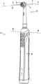
도 1은 본 발명에 따른 예시적인 개인 위생 장치의 도면.
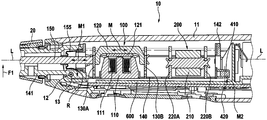
도 2는 본 발명에 따른 개인 위생 장치의 일 섹션을 통해 절단된 단면도.
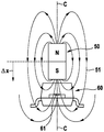
도 3은 동축으로 정렬된 센서 영구 자석과 홀 센서 사이의 관계의 개략도.
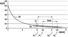
도 4는 거리 x에 따른 센서 영구 자석의 자속 밀도(magnetic flux density)(B)의 도면.
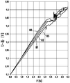
도 5는 개인 위생 장치들의 4개의 상이한 샘플에 대한 인가된 외부 힘(F)에 따른 홀 전압(U-HALL)의 측정치를 나타내는 그래프.
도 6은 2개의 막대형(rod-like) 스프링 요소를 포함하는 스프링 유닛 및 모터 캐리어의 격리된 도면.
도 7은 예시적인 개인 위생 장치의 모터 캐리어, 스프링 유닛 및 섀시의 상세부의 절단 단면도.
도 8은 본 발명에 따른 예시적인 개인 위생 장치의 개략도.
도 9는 모터 캐리어, 보유 요소, 및 2개의 막대형 스프링 요소를 포함하는 스프링 유닛의 일부분을 도시하는, 개인 위생 장치의 상세부의 도면.The invention will be further described by the detailed description and discussion of exemplary embodiments with reference to the drawings. In the drawing,
1 is a diagram of an exemplary personal hygiene device in accordance with the present invention.
2 is a cross-sectional view cut through a section of the personal hygiene device according to the present invention.
3 is a schematic diagram of the relationship between a coaxially aligned sensor permanent magnet and a Hall sensor.
4 is a diagram of magnetic flux density (B) of a sensor permanent magnet along a distance x.
5 is a graph showing measurements of Hall voltage (U-HALL) according to the applied external force (F) for four different samples of personal hygiene devices.
6 is an isolated view of a spring unit and a motor carrier comprising two rod-like spring elements.
7 is a cross-sectional cutaway view of details of a motor carrier, spring unit and chassis of an exemplary personal hygiene device.
8 is a schematic diagram of an exemplary personal hygiene device in accordance with the present invention.
9 is a view of a detail of a personal hygiene device, showing a portion of a spring unit comprising a motor carrier, a retaining element, and two rod-like spring elements.
본 설명의 맥락에서, "개인 위생"은 피부와 그의 부속기(adnexa)(즉, 모발과 손발톱) 및 치아와 구강(혀, 잇몸 등을 포함함)의 양육(nurture)(또는 케어(care))을 의미할 것이며, 여기서, 목표는 한편으로는 질병의 예방 및 건강("위생")의 유지 및 강화이고, 다른 한편으로는 피부와 그의 부속기의 외양의 개선 및 미용적 처치이다. 이는 웰빙의 유지 및 강화를 포함할 것이다. 이는 피부 케어, 모발 케어, 및 구강 케어뿐만 아니라 손발톱 케어를 포함한다. 이는 수염 케어, 면도 및 제모와 같은 다른 몸단장(grooming) 활동을 추가로 포함한다. 따라서, "개인 위생 장치"는 그러한 양육 또는 몸단장 활동을 수행하기 위한 임의의 장치, 예컨대 (미용) 피부 처치 장치, 예를 들어 전기 피부 마사지 장치 또는 전기 피부 브러시; 전기 면도기 또는 트리머(trimmer); 전기 제모기(epilator); 및 전동 칫솔, 전기 플로저(flosser), 전기 세척기(irrigator), 전기 혀 세정기(tongue cleaner), 또는 전기 잇몸 마사지기와 같은 전기 구강 케어 장치를 의미한다. 이는 제안된 개인 위생 장치가 이들 분야 중 하나 또는 몇몇 다른 분야에서보다 이들 양육 또는 장치 분야 중 하나 또는 몇몇에서 더욱 현저한 이익을 가질 수 있음을 배제하지 않아야 한다.In the context of this description, “personal hygiene” refers to the nurture (or care) of the skin and its appendages (ie, hair and nails) and the teeth and mouth (including the tongue, gums, etc.). Here, the goal is to prevent disease and maintain health ("hygiene") on the one hand, and improve cosmetic appearance and cosmetic treatment on the other hand. This will include maintaining and enhancing well-being. This includes skin care, hair care, and oral care as well as nail care. It further includes other grooming activities such as beard care, shaving and hair removal. Thus, a “personal hygiene device” can be any device for performing such nurturing or grooming activities, such as a (beauty) skin treatment device, such as an electric skin massage device or an electric skin brush; Electric shaver or trimmer; An electric epilator; And electric oral care devices such as electric toothbrushes, electric flossers, electric irrigators, electric tongue cleaners, or electric gum massagers. This should not exclude that the proposed personal hygiene device may have more significant benefits in one or several of these parenting or device areas than in one or several other areas of these areas.
본 발명에서 용어 "처치 힘" 또는 "외부 처치 힘"이 사용되는 경우, 이는 처치 방향으로 처치 헤드에 인가되는 힘을 의미하고, 이러한 처치 방향은 모터 캐리어의 피벗 축에 의해 그리고 인가된 처치 힘이 모터 캐리어를 피벗 축을 중심으로 피벗시키는 모멘트를 제공하도록 처치 힘이 인가되는 브러시 헤드에서의 지점에 의해 한정되는 평면에 수직이다. 총 인가된 처치 힘은 처치 방향으로의 처치 힘보다 더 높을 수 있지만, 다른 방향들로 작용하는 처치 힘의 성분들이 논의된 구성에 의해 측정가능하지 않기 때문에, 이들은 고려되지 않는다. 전형적으로, 처치 방향 이외의 방향으로 처치 헤드에 인가되는 힘은 베어링에 흡수되거나 개인 위생 장치의 탄성 변형에 의해 흡수된다.When the term "treatment force" or "external treatment force" is used in the present invention, it means a force applied to the treatment head in the treatment direction, the treatment direction being applied by the pivot axis of the motor carrier and the applied treatment force. It is perpendicular to the plane defined by the point at the brush head where the treatment force is applied to provide a moment to pivot the motor carrier about the pivot axis. The total applied treatment force may be higher than the treatment force in the treatment direction, but these are not considered because the components of the treatment force acting in different directions are not measurable by the configuration discussed. Typically, the force applied to the treatment head in a direction other than the treatment direction is absorbed by the bearing or by elastic deformation of the personal hygiene device.
손잡이에 대한 모터 캐리어의 운동을 측정하는 본 목적을 위해 홀 센서가 사용될 때, 전체 설계의 몇몇 난제가 충족되어야 한다:When a hall sensor is used for this purpose of measuring the motion of the motor carrier relative to the handle, some challenges of the overall design must be met:
1. 전동 칫솔의 손잡이 내의 공간은 제한되는데, 그 이유는 특히 가동 부분, 즉 모터 캐리어가 전형적으로 개인 위생 장치의 가장 많은 체적을 소비하는 부품들 중 하나인 적어도 완전한 모터를 지지하기 때문이다.One. The space within the handle of the electric toothbrush is limited, especially because the movable part, ie the motor carrier, supports at least a complete motor, typically one of the most consuming parts of the personal hygiene device.
2. 개인 위생 장치의 모든 부품은 고유의 제조 공차를 가져, 센서 영구 자석 및 홀 센서의 서로에 대한 최종 상대 위치들이 개별 개인 위생 장치들 사이에서 소정의 변동을 갖게 된다.2. All parts of the personal hygiene device have unique manufacturing tolerances, such that the sensor permanent magnet and the final relative positions of the Hall sensor to each other have a certain variation between the individual personal hygiene devices.
3. 홀 센서의 효율 범위는 가능한 한 양호하게 사용되어야 한다.3. The efficiency range of the Hall sensor should be used as good as possible.
4. 피벗 장착된 모터 캐리어에 작용하는 지구의 중력은 지구의 중력장에 대한 장치의 배향에 따라 홀 전압의 변화를 도입할 것인데, 그 이유는 가동 부품(예컨대, 모터 캐리어)은 이어서 이러한 추가적인 힘에 의해 영향을 다소 영향을 받으며, 장치의 추가의 진동은 홀 전압 신호의 잡음 플로어(noise floor)에 추가될 것이다.4. Earth's gravitational force acting on the pivoted motor carrier will introduce a change in the Hall voltage depending on the orientation of the device with respect to the Earth's gravitational field, because moving parts (eg motor carriers) are then somewhat affected by this additional force Affected, additional vibration of the device will be added to the noise floor of the hall voltage signal.
5. 센서 영구 자석에 대한 비용은 허용가능한 수준으로 유지되어야 한다.5. The cost for the sensor permanent magnet should be kept at an acceptable level.
앞서 언급된 난제를 다루기 위해, 본 명세서에 제안된 설비(arrangement)의 설계의 다양한 상세부가 고려되었으며, 여기서 하기의 설계 태양들 각각은 단독으로(즉, 그 자체로) 그리고 또한 다른 태양들 중 하나 이상 또는 심지어 전부와 조합하여 고려되었다(이는, 하기의 특징들 각각이 개별적으로 그리고 또한 모순적인 조합으로 이어지지 않는 한 하나 또는 수 개의 특징들과의 모든 가능한 조합으로 개시된 특징임을 의미함):To address the aforementioned challenges, various details of the design of the arrangement proposed herein have been considered, where each of the following design aspects alone (ie itself) and also one of the other aspects It has been considered in combination with the above or even all (which means that each of the following features is disclosed individually and in all possible combinations with one or several features unless it also leads to contradictory combinations):
1. 센서 영구 자석의 형상은 원통형 또는 디스크형이도록 선택될 수 있다(여기서, 후자는 단지 직경보다 더 낮은 높이를 갖는 원통을 지칭한다).One. The shape of the sensor permanent magnet can be selected to be cylindrical or disc-shaped (here the latter only refers to a cylinder having a height lower than the diameter).
2.
홀 센서에 대면하는 센서 영구 자석의 표면의 면적은 약 3 ㎟ 내지 15 ㎟의 범위, 특히 7 ㎟ 내지 13 ㎟의 범위 내이도록 선택될 수 있다.2.
The area of the surface of the sensor permanent magnet facing the Hall sensor can be selected to be in the range of about 3
3. 센서 영구 자석의 높이는 1 mm 내지 3 mm의 범위, 특히 1.5 mm 내지 2.5 mm의 범위 내에 있도록 설정될 수 있고, 또한, 특히 센서 영구 자석의 높이는 2.0±0.25 mm의 범위 내일 수 있다.3. The height of the sensor permanent magnet can be set to be in the range of 1 mm to 3 mm, in particular of 1.5 mm to 2.5 mm, and in particular, the height of the sensor permanent magnet can be in the range of 2.0 ± 0.25 mm.
4.
센서 영구 자석의 체적은 10 ㎣ 내지 40 ㎣의 범위, 특히 15 ㎣ 내지 30 ㎣의 범위 내에 있도록 설정될 수 있다.4.
The volume of the sensor permanent magnet can be set to be within the range of 10
5. 센서 영구 자석의 잔류 자기(magnetic remanence)는 200 mT 내지 2000 mT의 범위, 특히 300 mT 내지 1500 mT의 범위 내이도록 한정될 수 있다.5. The magnetic remanence of the sensor permanent magnet may be limited to be in the range of 200 mT to 2000 mT, in particular 300 mT to 1500 mT.
6. 센서 영구 자석의 잔류 자기와 센서 영구 자석의 체적의 곱은 3000 mT·㎣ 내지 20000 mT·㎣, 특히 12000 mT·㎣ 내지 18000 mT·㎣의 범위 내이도록 한정될 수 있다.6. The product of the residual magnet of the sensor permanent magnet and the volume of the sensor permanent magnet may be limited to be in the range of 3000 mT · ㎣ to 20000 mT · ㎣, particularly 12000 mT · ㎣ to 18000 mT · ㎣.
7. 센서 영구 자석 및 홀 센서의 규정된 위치들은 센서 영구 축의 원통 축이 홀 센서의 유효 영역을 중심에서 수직으로 교차하도록 한정될 수 있다. 특히, 이때 센서 영구 자석 및 홀 센서의 상대 운동이 본질적으로 원통 축을 따라 일어난다는 것이 한정될 수 있다.7. The defined positions of the sensor permanent magnet and the Hall sensor can be defined such that the cylindrical axis of the sensor permanent axis intersects the effective area of the Hall sensor vertically from the center. In particular, it can be limited here that the relative motion of the sensor permanent magnet and the Hall sensor occurs essentially along the cylindrical axis.
8. 영구 자석과 홀 센서 사이의 이동 거리는 0.5 mm 초과, 특히 0.8 mm 이상이도록, 그리고 더욱 특히 약 1 mm이도록 한정될 수 있다.8. The distance of travel between the permanent magnet and the Hall sensor can be defined to be greater than 0.5 mm, in particular 0.8 mm or more, and more particularly about 1 mm.
9. 모터 캐리어가 휴지 위치(rest position)에 있을 때(즉, 처치 헤드에 하중이 작용하지 않을 때, 이 위치는 이때 무하중(no-load) 위치로도 불릴 수 있음)의 센서 영구 자석과 홀 센서 사이의 초기 거리는, 2 mm 내지 6 mm의 범위, 특히 3.5 mm 내지 5.5.mm의 범위 내이도록 한정될 수 있으며, 또한 특히 초기 거리는 4.5±0.25 mm로 설정되었다.9. Sensor permanent magnet and hall sensor when the motor carrier is in the rest position (i.e., when no load is applied to the treatment head, this position can also be referred to as a no-load position at this time) The initial distance between may be limited to be in the range of 2 mm to 6 mm, especially in the range of 3.5 mm to 5.5.mm, and in particular the initial distance was set to 4.5 ± 0.25 mm.
10. 센서 영구 자석의 자기장 강도, 홀 센서와 센서 영구 자석 사이의 초기 거리, 및 이동 거리는, 자기장 강도의 거동이 감지가능 방식으로 홀 센서의 선형 응답 범위를 이용하므로 이러한 거동이 대략 선형인 자기장의 꼬리(tail)에서 시스템이 작동하도록 설정될 수 있다.10. The magnetic field strength of the sensor permanent magnet, the initial distance between the Hall sensor and the sensor permanent magnet, and the travel distance are the tails of the magnetic field where this behavior is approximately linear because the behavior of the magnetic field strength uses the linear response range of the Hall sensor in a detectable manner. tail), the system can be configured to operate.
11. 홀 센서가 10 mT 내지 200 mT, 특히 30 mT 내지 90 mT의 범위 내에 있는 선형 응답 범위를 갖는다는 것이 한정될 수 있는데, 즉 홀 센서는 40 mT 또는 80 mT의 선형 응답 범위를 가질 수 있다.11. It can be defined that the Hall sensor has a linear response range within the range of 10 mT to 200 mT, in particular 30 mT to 90 mT, that is, the Hall sensor can have a linear response range of 40 mT or 80 mT.
12. 제1 또는 최소 검출가능 임계 힘 값은 0.5 N 내지 1.5 N의 범위 내이도록 설정될 수 있고, 무하중 조건과 제1 검출가능 임계 힘 사이에서 센서 영구 자석에 대한 홀 센서의 이동 거리는 0.15 mm 이상이도록 설정될 수 있다.12. The first or minimum detectable threshold force value can be set to be in the range of 0.5 N to 1.5 N, and the movement distance of the Hall sensor to the sensor permanent magnet between the no-load condition and the first detectable threshold force is 0.15 mm or more. Can be set.
13. 최대 검출가능 힘 값은 2.0 N 내지 4.0 N의 범위, 특히 2.5 N 내지 3.5 N의 범위 내이도록 설정될 수 있다(즉, 설계는 예컨대 최대 검출가능 힘 값에 도달될 때 홀 센서 선형 감도 범위가 종료하도록 선택될 수 있거나, 대안적으로 또는 추가적으로, 최대 검출가능 힘 값에 도달되어 추가의 피벗이 기계적으로 억제될 때 모터 캐리어가 맞닿는 적어도 하나의 스토퍼 요소가 제공될 수 있음).13. The maximum detectable force value can be set to be in the range of 2.0 N to 4.0 N, especially 2.5 N to 3.5 N (i.e., the design ends, for example, the Hall sensor linear sensitivity range ends when the maximum detectable force value is reached. Or alternatively or additionally, at least one stopper element to which the motor carrier abuts when the maximum detectable force value is reached and further pivot is mechanically restrained may be provided).
홀 센서의 감지 영역은 전형적으로 비교적 작은데, 예컨대 감지 영역은 대략 1 ㎟ 이하일 수 있고, 예컨대 홀 센서의 감지 영역은 0.2 mm의 모서리 길이를 갖는 사각형일 수 있어서, 활성 영역은 이때 0.04 ㎟이다. 홀 센서와 센서 영구 자석 사이의 감지가능 거리에서 관련 강도의 자속 밀도를 제공하기 위해, 홀 센서에 대면하는 센서 영구 자석의 영역은 3 ㎟ 내지 15 ㎟의 범위, 특히 7 ㎟ 내지 13 ㎟의 범위 내이도록 선택되었다. 이때, 홀 센서의 감지 영역(흔히 원형 영역으로서 근사화됨)은 센서 영구 자석의 영역과 대조적으로 대략 점형(point-like)으로서 간주될 수 있다. 그러한 조건 하에서, 이때 원통형 센서 영구 자석(홀 센서에 대면하는 원통의 단부 면이 이때 원형 형상을 가짐)을 사용하는 것과, 홀 센서의 감지 영역과 동축이 되도록(또는 홀 센서의 점형 감지 영역이 원통형 센서 영구 자석의 원통 축 상에 놓이도록) 센서 영구 자석을 위치시키는 것이 실제적인 것으로 간주된다. 이는 물론 다른 형상의 센서 영구 자석이 또한 사용될 수 있는 것을 배제하지 않을 것인데, 예컨대 센서 영구 자석의 단부 면은 사각 형상, 임의의 다른 기하학적 형상, 또는 심지어 불규칙한 형상을 가질 수 있다. 홀 센서에서의 센서 영구 자석의 자속 밀도는 센서 영구 자석의 두께에 의해 더 적은 정도로만 증가될 수 있다. 따라서, 두께는 1 mm 내지 3 mm의 범위, 특히 1.5 mm 내지 2.5 mm의 범위 내일 수 있으며, 또한, 특히 두께는 2±0.25 mm의 범위 내일 수 있다.The sensing area of the Hall sensor is typically relatively small, for example the sensing area can be approximately 1 mm2 or less, for example the sensing area of the Hall sensor can be a rectangle with an edge length of 0.2 mm, so the active area is 0.04 mm2 at this time. In order to provide the magnetic flux density of the relevant intensity at a detectable distance between the Hall sensor and the sensor permanent magnet, the area of the sensor permanent magnet facing the Hall sensor is in the range of 3 ㎟ to 15 ㎟, especially 7 ㎟ to 13 ㎟. It was chosen to be. At this time, the sensing area of the Hall sensor (often approximated as a circular area) can be regarded as approximately point-like in contrast to the area of the sensor permanent magnet. Under such conditions, using a cylindrical sensor permanent magnet (the end face of the cylinder facing the hall sensor at this time has a circular shape), and coaxial with the sensing area of the hall sensor (or the point sensing area of the hall sensor is cylindrical) It is considered practical to position the sensor permanent magnet (to lie on the cylindrical axis of the sensor permanent magnet). This will of course not exclude that other shaped sensor permanent magnets can also be used, for example the end face of the sensor permanent magnet can have a square shape, any other geometric shape, or even an irregular shape. The magnetic flux density of the sensor permanent magnet in the Hall sensor can only be increased to a lesser extent by the thickness of the sensor permanent magnet. Accordingly, the thickness can be in the range of 1 mm to 3 mm, in particular in the range of 1.5 mm to 2.5 mm, and in particular, the thickness can be in the range of 2 ± 0.25 mm.
일부 연구된 실시예에서, 센서 영구 자석은 NdFeBr로 제조되었고 1350 mT의 잔류 자기를 가졌으며, 형상은 3.8 mm의 직경 및 2 mm의 원통 높이를 갖는 원통형이었다. 센서 영구 자석이 홀 센서에 대해 4.4 mm의 거리에 위치되었고, 무하중 조건과 최대로 검출가능한 외부 처치 힘 사이에서 홀 센서를 향한 이동 거리는 1 mm였다. 다른 실시예에서, 이동 거리는 훨씬 더 높은데, 예컨대 1.1 mm, 1.2 mm, 1.3 mm, 1.4 mm, 또는 1.5 mm이다.In some studied examples, the sensor permanent magnet was made of NdFeBr and had a residual magnet of 1350 mT, and the shape was cylindrical with a diameter of 3.8 mm and a cylinder height of 2 mm. The sensor permanent magnet was positioned at a distance of 4.4 mm relative to the Hall sensor, and the travel distance towards the Hall sensor between the no-load condition and the maximum detectable external treatment force was 1 mm. In other embodiments, the travel distance is much higher, such as 1.1 mm, 1.2 mm, 1.3 mm, 1.4 mm, or 1.5 mm.
일부 개인 위생 장치의 경우, 특히 칫솔의 경우, 외부 처치 힘은 사용자가 브러시 헤드를 치아에 대항하여 누르는 힘이다. 효과적이기 위하여, 최소의 힘(즉, 제1 임계 힘 값)이 적용될 것이고, 특히 자극으로부터 잇몸을 보호하기 위하여, 최대 힘(즉, 제2 임계 힘 값)이 초과되지 않아야 한다는 것이 일반적으로 알려져 있다. 따라서, 사용자가 제1 임계 힘 값과 제2 임계 힘 값 사이의 이러한 범위 내에 있는지 여부를 검출하고 사용자에게 인가된 힘을 전달할 수 있는 것이 목적이다. 최소 및 최대 힘은 사용되는 처치 헤드의 유형에 어느 정도 의존할 수 있고, 또한 사용자 선호도에 의존할 수 있다. 최소 힘(제1 임계 힘 값)은 0.5 N 내지 1.5 N의 범위 내에 그리고 특히 0.5 N 내지 1.0 N의 범위 내에 있을 수 있다. 최대 힘(제2 임계 힘 값)은 1.5 N 내지 3.5 N의 범위 내에, 특히 2.0 N 내지 3.0 N의 범위 내에 있을 수 있다. 시스템은 2.0 N 및 4.0 N의 범위 내에서, 특히 2.5 N 내지 3.5 N의 범위 내에서 인가되어야 하는 최대 힘보다 더 높은 최대 외부 처치 힘을 검출할 수 있도록 배열될 수 있다. 연구된 실시예에서, 최소 힘은 0.75 N으로 설정되었고, 최대 힘은 2.15 N으로 설정되었으며, 최대 검출가능 힘은 3.0 N으로 설정되었다. 무하중 상태와 최대 검출가능 힘의 인가 사이에서의 센서 영구 자석의 이동 거리가 1.0 mm일 때, 무하중 조건과 최소 힘의 인가 사이에서의 이동 거리는 0.25 mm이다. 이와 관련하여, 다양한 제조 공차가 고려되어야 한다. 따라서, 이동 거리가 1.0 mm이도록 설계되는 경우, 자석의 크기로부터 홀 센서 및 센서 영구 자석의 위치들까지의 범위인 제조 공정에서의 전체 허용오차는 최대 약 0.1 mm로 용이하게 합계된다. 이동 거리는 0.5 mm 미만이도록 선택되지 않아야 하는데, 그 이유는 이때 최소 힘이 언급된 공차로 인해 신뢰성 있게 검출되지 않을 수 있기 때문이다. 1.0 mm 초과의 이동 거리는 확실히 고려되며, 여기서 구성 체적 등은 이를 허용하는데, 예컨대 1.3 m의 이동 거리가 선택될 수 있다.In some personal hygiene devices, especially in the case of toothbrushes, the external treatment force is the force the user presses the brush head against the tooth. In order to be effective, it is generally known that a minimal force (i.e., the first critical force value) will be applied, and the maximum force (i.e., a second critical force value) should not be exceeded, especially to protect the gums from irritation. . Accordingly, it is an object to be able to detect whether the user is within this range between the first threshold force value and the second threshold force value and deliver the applied force to the user. The minimum and maximum forces may depend to some extent on the type of treatment head used, and may also depend on user preferences. The minimum force (first critical force value) can be in the range of 0.5 N to 1.5 N and in particular in the range of 0.5 N to 1.0 N. The maximum force (second critical force value) can be in the range of 1.5 N to 3.5 N, in particular in the range of 2.0 N to 3.0 N. The system can be arranged to detect a maximum external treatment force that is higher than the maximum force that should be applied within the range of 2.0 N and 4.0 N, especially within the range of 2.5 N to 3.5 N. In the studied example, the minimum force was set to 0.75 N, the maximum force was set to 2.15 N, and the maximum detectable force was set to 3.0 N. When the movement distance of the sensor permanent magnet between the unloaded state and the application of the maximum detectable force is 1.0 mm, the movement distance between the application of the minimum force and the no-load condition is 0.25 mm. In this regard, various manufacturing tolerances should be considered. Thus, when the travel distance is designed to be 1.0 mm, the overall tolerance in the manufacturing process ranging from the size of the magnet to the positions of the Hall sensor and the sensor permanent magnet is easily summed up to about 0.1 mm. The travel distance should not be selected to be less than 0.5 mm, since at this time the minimum force may not be reliably detected due to the stated tolerances. A travel distance of more than 1.0 mm is certainly considered, where a construction volume or the like allows this, for example a travel distance of 1.3 m can be selected.
홀 센서는 특히 홀 전압을 나타내고 따라서 처치 헤드에 인가된 처치 힘을 나타내는 홀 센서로부터의 신호를 수신하는 제어기에 결합될 수 있다. 제어기는 특히 홀 센서로부터 수신된 신호 및 적어도 하나의 임계 힘 값에 따라 개인 위생 장치의 동작을 개시하도록 배열될 수 있다. 개인 위생 장치의 동작은, 너무 큰 힘이 인가되고 있음을 나타내는 제2 임계 힘 값보다 인가된 처치 힘이 더 높다는 것을 홀 센서로부터의 신호가 나타낼 때, 모터의 정지 또는 모터 진폭의 감소일 수 있다.The Hall sensor can be coupled to a controller that receives a signal from the Hall sensor, in particular indicating the Hall voltage and thus the treatment force applied to the treatment head. The controller can in particular be arranged to initiate the operation of the personal hygiene device according to the signal received from the hall sensor and at least one threshold force value. The operation of the personal hygiene device may be a stop of the motor or a reduction in the motor amplitude when a signal from the hall sensor indicates that the applied treatment force is higher than a second threshold force value indicating that too much force is being applied. .
개인 위생 장치는 제어기에 결합된 표시 유닛을 추가로 포함할 수 있고, 제어기는 이때 인가된 처치 힘이 제1 임계 힘 값 미만 또는 제1 임계 힘 값 이상인지 여부 또는 부가적으로 인가된 처치 힘이 제1 임계 힘 값과 제2 임계 힘 값 사이에 있는지 여부를 시각적으로 검출가능하고/하거나 청각적으로 검출가능하고/하거나 촉각적으로 검출가능한 신호에 의해 사용자에게 나타내도록 배열될 수 있다. 예컨대, 표시 유닛 및 제어기는, 인가된 처치 힘이 제1 임계 힘 값 미만임을 예컨대 백색 광 신호와 같은 중간색에 의해, 인가된 처치 힘이 제1 임계 힘 값과 제2 임계 힘 값 사이에 있음(즉, 인가된 처치 힘이 의도된 범위 내에 있음)을 녹색 광 신호에 의해, 그리고 인가된 처치 힘이 제2 임계 힘 값 초과임을 적색 광 신호에 의해, 사용자에게 전달하도록 배열될 수 있다. 표시된 색상의 급격한 변화 대신에, 광 신호의 색상이 점진적으로 변화될 수 있다. RGB-LED는 표시된 광 신호의 그러한 점진적인 변화를 허용한다.The personal hygiene device may further include an indicator unit coupled to the controller, wherein the controller is configured such that whether the applied treatment force is less than or equal to or greater than the first threshold force value or additionally, the applied treatment force is applied. It may be arranged to indicate to the user by a signal that is visually detectable and / or audiblely detectable and / or tactilely detectable as to whether it is between the first threshold force value and the second threshold force value. For example, the display unit and the controller may have the applied treatment force between the first and second critical force values, for example, by an intermediate color, such as a white light signal, that the applied treatment force is less than the first critical force value ( That is, the applied treatment force is within the intended range) by the green light signal, and by the red light signal that the applied treatment force is above the second threshold force value, it can be arranged to transmit to the user. Instead of a sudden change in the displayed color, the color of the optical signal can be gradually changed. RGB-LED allows such a gradual change in the displayed light signal.
개인 위생 장치는 사용자가 개인 위생 장치의 파라미터에 영향을 미치게 하는, 특히 제1 및/또는 제2 임계 힘 값을 설정하게 하는 사용자 인터페이스를 포함할 수 있다.The personal hygiene device can include a user interface that allows the user to influence the parameters of the personal hygiene device, in particular to set first and / or second critical force values.
개인 위생 장치는 개인 처치 장치와 함께 사용되는 부착물 또는 처치 헤드의 유형을 검출하도록 배열될 수 있다. 예컨대, 부착물은 RFID 칩을 포함할 수 있고, 손잡이는 처치 헤드의 유형이 결정될 수 있도록 RFID 판독기 유닛을 포함할 수 있다. 제어기는 이때 검출된/결정된 처치 헤드에 기초하여 적어도 제1 임계 힘 값을 자동으로 설정하도록 배열될 수 있다. 적어도 제1 임계 힘 값은 메모리 유닛에 저장될 수 있다.The personal hygiene device can be arranged to detect the type of attachment or treatment head used with the personal care device. For example, the attachment can include an RFID chip, and the handle can include an RFID reader unit so that the type of treatment head can be determined. The controller can then be arranged to automatically set at least a first threshold force value based on the detected / determined treatment head. At least the first threshold force value may be stored in the memory unit.
개인 위생 장치는, 제어기가 0의 인가된 외부 처치 힘에서의 홀 센서로부터의 신호 및 처치 헤드에 작용하는 미리 정해진 힘에서의 적어도 하나의 추가 홀 신호를 사용하여 홀 센서로부터의 신호와 처치 헤드에 인가되는 처치 힘의 값 사이의 관계를 결정하여서 교정하는 교정 모드를 갖도록 배열될 수 있다. 교정은 특히 제어된 환경에서 제조자에 의해 사용될 수 있는데, 여기서 제어된 방식으로, 미리 정해진 처치 힘이 처치 헤드에 인가될 수 있다. 교정 모드는 개인 위생 장치를 판매 패키지 내에 패킹하기 직전에 조립 공정에 사용될 수 있다.The personal hygiene device uses a signal from the Hall sensor at a predetermined force acting on the treatment head and a signal from the Hall sensor at a zero applied external treatment force to the signal and treatment head from the Hall sensor. It can be arranged to have a calibration mode that determines and corrects the relationship between values of the applied treatment force. Calibration may be used by the manufacturer, particularly in a controlled environment, where in a controlled manner, a predetermined treatment force can be applied to the treatment head. The calibration mode can be used in the assembly process just before packing the personal hygiene device into the sales package.
또한, 제어기는 무하중 조건에 대한 홀 센서 신호 값을 자동으로 리셋하도록 배열될 수 있으며, 특히 제어기는 개인 위생 장치가 충전기 스탠드에 있는지 여부를 (예컨대, 이미 기술된 바와 같은 RFID 식별을 사용하여) 또는 이동되지 않고서 직립한 위치에 있는지 여부를 (예컨대, 가속도계의 사용에 의해) 검출하여 이들 조건 중 적어도 하나 하에서의 무하중 상태에 대해 홀 신호 값의 자동 리셋을 수행하도록 배열될 수 있다.In addition, the controller can be arranged to automatically reset the Hall sensor signal value for no-load conditions, especially the controller whether or not the personal hygiene device is on the charger stand (eg, using RFID identification as already described). Or it can be arranged to detect whether it is in an upright position without being moved (eg, by use of an accelerometer) and perform an automatic reset of the Hall signal value for a no-load condition under at least one of these conditions.
도 1은 전동 칫솔로서 실현된 개인 위생 장치(1)의 예시적인 실시예의 도면이다. 개인 위생 장치(1)는 처치 헤드(3)를 갖는 특히 탈착가능 부착물(2)을 포함하지만, 처치 헤드가 개인 위생 장치(1)의 탈착불가능 구조체에 또한 제공될 수 있다. 처치 헤드(3)는 여기서 브러시 헤드로서 실현되고, 당업계에 일반적으로 알려진 바와 같이 축(4)을 중심으로 하는 종동식 진동 회전을 위해 장착된다. 부착물(2)은 개인 위생 장치(1)의 손잡이(5)에 부착된다. 손잡이(5)는 특히 처치 헤드(3)를 운동으로 구동하기 위한 모터를 내장할 수 있다. 일정 방향(7)으로 처치 헤드에 작용하는 처치 힘(6)은, 처치 힘이 처치 헤드(3)에 작용하는 지점과 피벗 축(8)에 의해 한정되는 평면에 수직인 힘 성분을 처치 힘(6)이 갖는다면 피벗 축(8)을 중심으로 하는 부착물(2)의 피벗으로 이어진다(각각의 방향은 본 명세서에서 "처치 방향"으로 명명됨 - 도 1에 나타낸 방향(7)은 처치 방향과 정렬되지 않으며, 따라서 측정되는 인가된 처치 힘은 처치 헤드에 작용하는 총 처치보다 더 낮음). 처치 힘(6)은 특히 사용자의 처치 영역에 대항하여 처치 헤드(3)를 누름으로써 형성될 수 있다(예컨대, 도시된 실시예에서, 브러시 헤드는 소정 힘으로 치아에 대항하여 눌려져 브러시 헤드 상에 장착된 강모(bristle)들이 치아를 효과적으로 세정할 수 있음). 부착물(2)은 손잡이(5)의 커넥터 부분에 고정식으로 부착되고, 이 커넥터 부분은 이어서 손잡이(5) 내에 배치된 모터 캐리어와 고정식으로 연결된다. 모터 캐리어는 스프링 힘에 대항하여 피벗 축(8)을 중심으로 피벗하도록 장착된다.1 is a diagram of an exemplary embodiment of a
도 2는 길이방향 중심 평면을 따라 절개된 예시적인 개인 위생 장치(10)의 도면이고, 이 개인 위생 장치(10)는 부분적으로만 도시되어 있다(개인 위생 장치의 전방 단부 및 저부 단부는 도시되지 않음). 개인 위생 장치는 손잡이(11) 및 탈착가능 부착물(20)을 포함한다. 모터 캐리어(140)가 손잡이(11) 내에 배치되고 액슬(axle)(13) 상에 피벗 장착되어, 피벗 축(12)을 중심으로 하는 모터 캐리어(140)의 피벗을 허용한다.2 is a view of an exemplary
모터 캐리어(140)는 스프링-질량체 유형 공진 모터(100) 및 진동 상쇄 유닛(200)을 지지한다. 모터(100)는 고정자 레그(leg) 둘레에 권취된 코일(111)을 갖는 고정자 부분(110)을 포함한다(여기서, 고정자(110)는 연자성 재료로 만들어진 3개의 고정자 레그를 갖는 E-코어를 갖고, 코일은 중심 레그 둘레에 감김). 작동시, 제어기는 코일(111)에서 제1 주파수를 갖는 주기적인 교번하는 모터 구동 신호를 인가한다. 주기적인 교번하는 구동 신호는 코일(111)을 통한 주기적인 교류 흐름으로 이어지고, 따라서 주기적인 교번하는 전자기장의 발생으로 이어진다. 모터(100)는 전기자 부분(120)에 장착된 모터 영구 자석(121)을 갖는 전기자 부분(120)을 추가로 포함한다(여기서, 용어 "자석"이 그의 단수 형태로 사용되지만, 이는 하나 초과의 모터 영구 자석이 존재하는 것을 배제하지 않을 것임). 전기자 부분(120)은 스프링(130A, 130B)들에 의해 모터 캐리어(140)에 스프링 장착된다. 코일(111)이 작동시 주기적인 교번하는 전자기장을 발생시킬 때, 영구 자석(121)은 전자기장과 상호작용하고, 생성된 힘은 스프링(130A, 130B)들에 의해 제공되는 스프링 힘에 대항하여 전기자 부분(120)을 전기자 부분(120)의 휴지 위치로부터 길이 방향(L)을 따른 선형 진동 운동(M)으로 구동시킨다.The
진동 상쇄 유닛(200)은 질량체(210), 및 질량체(210)를 모터 캐리어(140)에 장착하는 스프링(220A, 220B)들을 포함한다. 진동 상쇄 유닛(200)은 모터 구동 신호의 제1 주파수와 일치하는 공진 주파수를 갖는다. 작동시, 모터가 제1 주파수로 진동하도록 구동될 때, 모터 캐리어(140)로 전달되는 진동은 주기적인 외부 여기 힘으로서 역할한다. 진동 상쇄 유닛(200)이 본질적으로 정확하게 그의 공진 주파수에서 여기되고, 결과적으로 전기자 부분(120)에 대해 반대 위상으로 진동할 것이기 때문에, 이는 모터 캐리어(140)로 전달되는 진동을 효율적으로 상쇄시킬 수 있다. 진동 상쇄 유닛(200)의 실제 공진 주파수는 제조 공차의 영향을 받기 때문에, 진동 상쇄 유닛(200)의 공진 주파수를 먼저 측정하고 이어서 모터 구동 신호의 제1 주파수를 진동 상쇄 유닛(200)의 결정된 공진 주파수로 설정하는 것이 합리적일 수 있다. 진동 상쇄 유닛이 모터 캐리어(140)에 장착되는 것으로 여기에 도시되지만, 이는 모터(100)에 의해 발생되는 진동이 모터 캐리어(140)로부터 액슬(13)을 통해 손잡이(11)로 전달될 것이기 때문에 손잡이(11)에 또한 장착될 수 있다.The
모터 캐리어(140)의 말단부에서, 홀더 요소(142)가 모터 캐리어(140)에 고정식으로 고정되며, 이 홀더 요소(142)는 홀 센서(420)에 근접하게 위치되는 센서 영구 자석(410)을 보유한다. 홀 센서(420)는 특히 PCB 상에 장착될 수 있으며, 이 PCB는 손잡이(11)에 대해 고정식으로 장착된다. 원칙적으로, 홀 센서(420)는 또한 모터 캐리어(140)에 대해 고정식으로 장착될 수 있지만, 이때 (에너지원이 장착된) 손잡이와 모터 캐리어(140) 사이의 반복되는 이동을 견딜 수 있는 전기 접속부가 제공될 필요가 있다.At the distal end of the
외부 처치 힘(F1)이 처치 헤드에 작용할 경우(화살표(F1)에 의해 표시됨), 이러한 힘(F1)은 이때 모터 캐리어(140) 및 모든 고정식으로 연결된 부품들이 (화살표(R)에 의해 표시된 바와 같이) 액슬(13)에 의해 한정되는 피벗 축(12)을 중심으로 피벗하는 것을 일으키며, 이 액슬(13)은 손잡이(11)에 장착되고 모터 캐리어(140)를 통해 연장된다. 이에 의해, 외부 처치 힘(F1)은, 여기에서 모터 캐리어(140)와 손잡이(11) 사이에 배치된 스프링 요소(도 6, 도 7 및 도 8 참조)에 의해 제공되는 스프링 힘에 대항하여 작용하여야 한다. 스프링 요소는 특히, 모터 캐리어(140)가 그의 휴지 위치에 있을 때 비-편의된 조건(unbiased condition)에 있도록 장착될 수 있는데, 즉 임의의 외부 처치 힘(F1)은 모터 캐리어(140)의 피벗 운동으로 직접 이어진다. 스프링 요소가 편의력(biasing force)을 인가하는 실시예에서, 모터 캐리어는 이때 일단 외부 처치 힘이 편의력을 극복하면 단지 피벗을 시작할 것이다. 일부 실시예에서, 비교적 작은 제1 임계 힘 값은 검출가능하여야 해서, 직접 피벗하는 비-편의된 모터 캐리어가 0의 외부 힘(무하중 조건)과 제1 검출가능 임계 힘 사이에서 최대 이동 거리를 적어도 제공하도록 한다.When the external treatment force F1 acts on the treatment head (indicated by the arrow F1), this force F1 is when the
도 3은 자속선(51)들에 의해 표시되는 자기장을 발생시키는 쌍극자(dipole)인 것으로 여기에 도시된 센서 영구 자석(50), 및 PCB 상에 자동 장착하기에 적합한 SMD 장치로서 여기에 도시된 홀 센서(60)의 개략도이다. 홀 센서(60)는 전형적으로 상대적으로 작은, 특히 약 1 ㎟ 이하, 예컨대 0.5 ㎟ 또는 0.25 ㎟ 또는 0.1 ㎟ 또는 0.01 ㎟인 감지 영역(61)을 갖는다. 쌍극자 자화(magnetization) 이외의 다른 자화, 예를 들어 사극자(quadrupole) 자화가 또한 가능하다. 센서 영구 자석(50)이 홀 센서(60)에 대해 이동될 때, 홀 센서(60)의 감지 영역에서의 자속 밀도는 변화하고, 홀 센서에 의해 각각의 홀 전압이 제공된다. 홀 센서는 홀 전압을 수신하고, 특히 이를 분석하기 위한 제어기와 특히 연결될 수 있다. 센서 영구 자석(50)과 홀 센서(60) 사이의 임의의 상대 변위가 홀 센서(60)의 감지 영역(61)에서의 자속 밀도의 변화 및 따라서 홀 전압의 변화로 이어질 것이지만, 센서 영구 자석(50)이, 예컨대 소정 처치 힘이 인가되는 경우 Δx의 이동 거리만큼, 홀 센서(60)를 향해 이동할 수 있는 것이 여기에 도시되어 있다. 특히, 센서 영구 자석(50) 및 홀 센서(60)는 중심축(C)에 대해 동축으로 배열되고, 센서 영구 자석(50)과 홀 센서 사이의 상대 운동은 본질적으로 중심축(C)을 따라 일어난다(도 2에 대하여 논의된 예에서 모터 캐리어의 피벗으로 인해, 약간 곡선의 이동이 일어날 것이며, 이는 본 목적을 위한 선형 운동으로 간주될 수 있음).FIG. 3 shows the sensor
본 개시 내용에서 논의된 센서 영구 자석은 영구 자석을 제조하기에 적합한 다양한 재료로 제조될 수 있다. 예컨대, 센서 영구 자석은 NdFeB 또는 SmCo와 같은 합금으로 제조될 수 있으며, 이 재료는 플라스틱 결합될 수 있거나 소결될 수 있다. 소결 NdFeB 자석은 1 내지 1.4 T의 범위의 잔류 자기를 가질 수 있다. 스트론튬 페라이트와 같은 경질 페라이트 재료들이 일반적으로 또한 가능하지만, 이들 재료의 잔류 자기가 전형적으로 약 400 mT 미만이다. 플라스틱 결합된 영구 자석의 잔류 자기는 흔히 600 mT 내지 700 mT의 범위 내이다.The sensor permanent magnets discussed in this disclosure can be made from a variety of materials suitable for making permanent magnets. For example, the sensor permanent magnet can be made of an alloy such as NdFeB or SmCo, and the material can be plastic bonded or sintered. The sintered NdFeB magnet can have residual magnetism in the range of 1 to 1.4 T. Hard ferrite materials, such as strontium ferrite, are also generally possible, but the residual magnetism of these materials is typically less than about 400 mT. The residual magnetism of plastic bonded permanent magnets is often in the range of 600 mT to 700 mT.
도 4는 홀 센서와 센서 영구 자석 사이의 거리(x)(mm 단위)에 따른 예시적인 센서 영구 자석의 자속 밀도 B(T 단위)를 곡선(70)으로서 도시하는 그래프이다. 단지 예시적인 2개의 추가의 곡선(71, 72)이 부분적으로 도시되어 있으며, 이 곡선(71, 72)들은 다양한 허용오차에 대한 자속 밀도의 의존성을 나타낼 것이다. 일부 실시예에서, 센서 영구 자석과 홀 센서 사이의 초기 거리는 X2 = 4.4 mm로 설정되고, 무하중 조건과 최대 검출가능 처치 힘 사이의 이동 거리는 (홀 센서를 향해) 1 mm일 것이어서, 단부 위치는 x1 = 3.4 mm에 있다. 이들 2개의 위치 사이의 자속 밀도의 변화는 홀 센서가 선형 홀 전압 신호를 제공해야 하는 전형적인 범위를 제공한다. 자속 밀도의 변화는, 예컨대 약 40 mT일 수 있다. 위치 공차 및/또는 크기 공차(소결된 NdFeB 영구 자석은 ±0.05 mm 내지 ±0.1 mm의 범위 내의 크기 허용오차를 용이하게 가질 수 있음)로 인해, 초기 거리 및 이동 거리는 또한 이동된 위치 x1' 및 x2'와 관련한 파선들로 나타낸 바와 같이 용이하게 이동할 수 있다. 이들 허용오차에 대처하기 위해, 더 큰 선형 범위, 예컨대 약 80 mT를 갖는 홀 센서가 선택되어야 하며, 이때 한정된 이상적인 위치 및 크기 등의 언급된 예시적인 40 mT 검출 범위가 선택된 홀 센서의 선형 80 mT 감도 범위 내에서 중심에 놓이도록 계획된다. 상기의 것이 일반적인 원리를 나타내는 단지 일례임에 유의한다. 센서 영구 자석 크기, 재료, 홀 센서에 대한 초기 거리 등에 따라, 예컨대 20 mT 또는 160 mT 등의 선형 감도 범위를 갖는 다른 홀 센서가 사용될 수 있다. 적합한 홀 센서는, 예컨대 알레그로(Allegro) A1304 시리즈(미국 매사추세츠주 소재의 알레그로 마이크로시스템즈, 엘엘씨(Allegro MicroSystems, LLC)로부터 입수가능함)로부터의 또는 다이오즈(Diodes) AH49F 시리즈(미국 텍사스주 소재의 다이오즈 인코포레이티드(Diodes Incorporated)로부터 입수가능함)로부터의 센서를 포함한다. 홀 센서의 감도는 10 ㎷/mT 내지 90 ㎷/mT의 범위 내일 수 있다.4 is a graph showing the magnetic flux density B (T unit) of the exemplary sensor permanent magnet according to the distance (x) (in mm) between the Hall sensor and the sensor permanent magnet as a
도 5는 몇몇 연구된 시작품(prototype)으로 행해진 측정 곡선(80, 81, 82, 83)들을 도시하는 그래프인데, 여기서 홀 전압 신호(U-Hall)(V 단위)는 인가된 처치 힘(F)(N 단위)의 함수로서 도시되어 있다. 측정 곡선(80 내지 83)은 0 N의 처치 힘과 3 N의 처치 힘 사이에서 본질적으로 선형이다. 예컨대, 0.8 N의 최소 검출가능 처치 힘 또는 제1 임계 힘 값은 2.5 N의 제2 임계 힘 값으로서 또한 측정가능하다. 곡선들의 차이로 인해, 시스템의 응답의 교정을 수행하는 것이 합리적이다. 선형 교정, 예컨대 무하중 조건에서 그리고 미리 정해진 처치 힘(예컨대, 2.0 N)에서 홀 전압을 측정하는 것이 충분할 수 있지만, 이는 교정이 2개 초과의 측정 지점을 가지고 작업되는 것을 배제하지 않을 것이다. 교정은 개인 위생 장치를 판매하기 전에 특히 제조 장소에서 행해질 수 있어서, 교정 파라미터(들)가 개인 위생 장치의 메모리에 저장될 수 있다.5 is a graph showing measurement curves 80, 81, 82, 83 made with some studied prototypes, where the Hall voltage signal (U-Hall) (in V) is the applied treatment force (F) (N units). The measurement curves 80-83 are essentially linear between 0 N treatment force and 3 N treatment force. For example, a minimum detectable treatment force of 0.8 N or a first threshold force value is also measurable as a second threshold force value of 2.5 N. Due to the differences in the curves, it is reasonable to perform calibration of the system's response. It may be sufficient to measure the Hall voltage at linear calibration, such as under no-load conditions and at a predetermined treatment force (eg, 2.0 N), but this will not preclude calibration from working with more than two measurement points. Calibration can be done before selling the personal hygiene device, particularly at the manufacturing site, so that the calibration parameter (s) can be stored in the memory of the personal hygiene device.
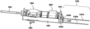
도 6은 모터(100A) 및 진동 상쇄 유닛(200A)을 지지하는 모터 캐리어(140A)의 도면이다. 구동 샤프트(150A)가 모터(100A)의 전기자 부분과 연결된다. 모터(100A)를 에너지원과 전기 접속하기 위해 S형 전기 커넥터(160A)가 사용될 수 있으며, 이러한 S형 커넥터는 개인 위생 장치의 손잡이에 대한, 인가된 처치 힘 하에서의 모터 캐리어(140A)의 작은 이동을 수용하기에 충분히 가요성이다. 홀더 요소(142A)가 모터 캐리어(140A)에서 고정식으로 고정되고, 센서 영구 자석(410A) 및 추가의 2개의 막대형 스프링 요소(5100A, 5101A)를 보유한다. 막대형 스프링 요소(5100A, 5101A)들은 모터 캐리어(140A)와 연결된 리셉터클(1424A)들 내에 일 단부에서 수용되고, 도 7에 관하여 더욱 상세히 설명되는 바와 같이 개인 위생 장치의 손잡이에 대해 고정된 각각의 보유 고정구들 내에 수용될 것이다. 막대형 스프링 요소(1500A, 1501A)들은 함께 스프링 힘을 제공하는 스프링 유닛(510A)을 형성하며, 스프링 힘에 대항하여 외부적으로 인가되는 처치 힘은 모터 캐리어(140A)를 피벗 축을 중심으로 피벗시키도록 작용할 필요가 있다.6 is a view of the
여기에서 논의된 막대형 스프링 요소(1500A, 1501A)들은 이들을 의도된 용도에 적합하게 하는 소정의 특성을 갖는다. 한편, 막대형 스프링 요소는 작은 제조 비용에도 불구하고 높은 정밀도로 제조될 수 있다. 그러한 높은 제조 품질(즉, 낮은 허용오차)은, 최소 검출가능 임계 힘 값의 측정 품질에 해로운, 인가된 처치 힘에 의해 극복될 필요가 있을 편의력을 본질적으로 도입하지 않고서 스프링 요소들이 장착될 수 있음을 뒷받침한다. 다른 한편, 막대형 스프링 요소는 제한된 구성 체적만을 사용하면서 상대적으로 높은 스프링 상수를 제공할 수 있다. 고 정밀도로 유사한 스프링 상수를 제공하는 코일 스프링 또는 판 스프링보다, 작은 직경 또는 작은 단면 형상의 긴 물체를 개인 위생 장치의 하우징 내에 수용하는 것이 더 용이하다. 또한, 막대형 스프링 요소가 본질적으로 직사각형인 단면을 갖도록 제조될 수 있기 때문에, 피벗 방향으로의 스프링 상수 및 수직 방향으로의 스프링 상수가 정밀하게 조정될 수 있다. 일부 연구된 실시예에서, 막대형 스프링 요소(1500A, 1501A)들 각각은 약 24 mm의 자유 스프링 길이 및 약 2 N/mm의 스프링 상수를 갖고, 스테인리스강 1.4310으로 제조되고, 0.8 mm × 1.2 mm의 치수를 갖는 직사각형 단면 형상을 갖는다.The rod spring elements 1500A, 1501A discussed herein have certain properties that make them suitable for their intended use. On the other hand, the rod-shaped spring element can be manufactured with high precision despite a small manufacturing cost. Such high manufacturing quality (i.e. low tolerance) allows spring elements to be mounted without essentially introducing the convenience that needs to be overcome by the applied treatment force, which is detrimental to the measurement quality of the minimum detectable critical force value. Support the presence. On the other hand, the rod-shaped spring element can provide a relatively high spring constant while using only a limited construction volume. It is easier to accommodate long objects of small diameter or small cross-sectional shape in the housing of the personal hygiene device than coil springs or leaf springs which provide similar spring constants with high precision. Further, since the rod-shaped spring element can be manufactured to have an essentially rectangular cross section, the spring constant in the pivot direction and the spring constant in the vertical direction can be precisely adjusted. In some studied embodiments, each of the rod-shaped spring elements 1500A, 1501A has a free spring length of about 24 mm and a spring constant of about 2 N / mm, made of stainless steel 1.4310, 0.8 mm × 1.2 mm It has a rectangular cross-sectional shape with dimensions of.
도 7은 홀더 요소(142B)가 고정식으로 장착되는 모터 캐리어(140B)의 단부를 통해 그리고 그 자체가 개인 위생 장치의 손잡이에 대해 고정식으로 장착되는 섀시(600B)를 통한 절단부의 상세부를 도시한다. 섀시(600B)는 특히 재충전가능 축전지와 같은 에너지원, 및 홀 센서를 포함한 개인 위생 장치의 전자 부품들이 상부에 장착되는 PCB를 지지할 수 있다. 홀더 요소(142B)는 막대형 스프링 요소(5100B)를 수용하기 위한 리셉터클(1424B)을 포함한다(다른 그러한 리셉터클은 특히 평행한 막대형 스프링 요소를 수용하기 위해 도 6에 도시되었던 바와 같이 홀더 요소(142B)의 반대측에 배치될 수 있음). 리셉터클(1424B)은 정렬된 반원통형 지탱 구조체(1422B)들이 막대형 스프링 요소(5100B)를 위한 지탱 지점을 제공하는 관통 구멍 또는 보어(1421B)를 갖는다. 더욱 상세히 설명되는 바와 같이, 막대형 스프링 요소(5100B)는 섀시(600B)에 고정식으로 장착되며, 따라서 홀더 요소(142B)에서의 막대형 스프링 요소(5100B)의 지탱은 리셉터클(1424B) 내에서의 막대형 스프링 요소(5100B)의 소정 이동성을 제공하여야 한다. 모터 캐리어(140B)가 예컨대 도 7에서 이중 화살표로 표시된 바와 같이 그의 피벗 축을 중심으로 약 1 mm 이동할 때, 막대형 스프링 요소(5100B)는 리셉터클(1424B) 내의 그의 지탱 내에서 피벗할 수 있어야 하고, 또한 섀시(600B)에 대한 모터 캐리어(140B)의 이동을 보상하기 위해 리셉터클(1424B)에 대해 선형으로 약간 이동하는 것이 가능하여야 한다. 언급된 요구되는 가요성에 대처하기 위한 대안적인 설계가 도 9와 관련하여 도시되고 논의된다.FIG. 7 shows the details of the cut through the end of the
섀시(600B)에 제공된 보유 고정구(610B)에 의해 막대형 스프링 요소(5100B)가 수용된다는 것이 도 7에 또한 도시되어 있다. 보유 고정구(610B)는 전방 클램프(6101B) 및 후방 클램프(6102B)를 포함한다. 절단부에서 볼 수 없지만, 전방 클램프(6101B) 및 후방 클램프(6102B)는 U-형상 리셉터클의 형태를 갖는다. 다른 실시예에서, 클램프는 본질적으로 O-형상 클램프로서 실현될 수 있다. 섀시는 2개 초과의 도시된 클램프를 포함할 수 있으며, 특히 섀시는 막대형 스프링 요소(5100B)를 고정식으로 보유하기 위한 3개, 4개, 5개, 6개, 7개, 8개 또는 심지어 그 초과의 클램프를 포함할 수 있다. 클램프(6101B 또는 6102B)들 중 적어도 하나, 그러나 특히 클램프들 각각은 클램프 내로의 막대-형상 스프링 요소(5100B)의 삽입을 용이하게 하기 위해 (도 7에 도시된 바와 같은) 모따기된 전방 면을 가질 수 있다.It is also shown in FIG. 7 that the
막대형 스프링 요소(5100B)는 지탱 지점(1422B)과 전방 클램프(6101B) 사이의 자유 길이(Lf)를 갖는다. 막대-형상 스프링 요소의 자유 길이(Lf)는 모터 캐리어(140B)의 피벗 이동에 대항하여 작용하는 스프링 상수를 결정한다. 예컨대, 막대-형상 스프링 요소(5100B)는 0.8 mm의 높이 및 1.2 mm의 폭, 24.3 mm의 자유 길이를 가질 수 있고, 이는 195,000 N/㎟의 E-모듈을 갖는 스프링강으로 제조될 수 있다. 이때, 막대형 스프링 요소마다 약 2.09 N/mm의 강성(즉, 스프링 상수)이 얻어지고, 2개의 막대형 스프링 요소가 사용되는 경우, 4.18 N/mm의 총 강성이 얻어진다. 자유 길이(Lf)를 적응시킴으로써, 스프링 유닛의 강성이 조정될 수 있다.The rod-shaped
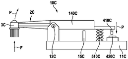
개인 위생 장치의 이동가능 모터 캐리어 및 손잡이에 각각 장착되는 센서 영구 자석 및 홀 센서의 일반적인 구조는 또한 기술되었던 바와 같은 공진 모터 대신에 일반적인 유형의 모터를 갖는 개인 위생 장치에 적용가능하다. 이는 손잡이(1C), 및 처치 헤드(3C)를 포함하는 헤드 섹션(2C)을 갖는 개인 위생 장치(10C)의 개략도인 도 8을 참조하여 논의된다. 헤드 섹션(2C)은 처치 헤드(3C)를 운동으로 구동시키기 위한 모터를 지지하는 모터 캐리어(140C)와 고정식으로 연결된다. 모터 캐리어(140C)는 피벗 축(12C) 주위에 피벗 장착된다. 외부 처치 힘(F)이 처치 방향으로 처치 헤드에 인가되는 경우에, 헤드 섹션(2C) 및 모터 캐리어(140C)는 도 8에 화살표(P)로 표시된 바와 같이 피벗 축(12C)을 중심으로 피벗한다. 모터 캐리어(140C)는 스프링 유닛(510C)에 의해 인가되는 스프링 힘에 대항하여 피벗 이동하도록 장착된다. 센서 영구 자석(410C)이 모터 캐리어(140C)에 장착되고, 홀 센서(420C)가 손잡이(11C)에 장착된다. 미리 결정된 최대 인가된 외부 처치 힘 초과에서 추가의 피벗 운동을 피하기 위해 스토퍼(stopper) 요소(15C)가 제공된다. 이전의 논의에서 센서 영구 자석 및 홀 센서에 대해 설명되었던 모든 것이 또한 도 8의 실시예에 적용된다.Sensors mounted on movable motor carriers and handles of personal hygiene devices respectively The general structure of permanent magnets and hall sensors is also applicable to personal hygiene devices having a common type of motor instead of a resonant motor as described. This is discussed with reference to FIG. 8 which is a schematic view of a
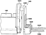
도 9는 홀더 요소(142D)가 고정식으로 장착되고, 홀더 요소(142D)가 리셉터클(1424D) 내에서 2개의 막대형 스프링 요소(5100D, 5101D)를 보유하는 모터 캐리어(140D)의 도면이다. 막대형 스프링 요소(5100B)의 피벗 운동 및 또한 약간의 선형 운동을 허용한, 도 7에 도시된 리셉터클(1424B) 내에 제공된 지탱과는 대조적으로, 도 9는 막대형 스프링 요소(5100D, 5101D)들이 리셉터클(1424D)들에 고정식으로 고정되는 실현을 도시한다. 예컨대, 막대형 스프링 요소(5100D, 5101D)들은 길이방향 연장 방향에 대해 언더컷(undercut)을 가질 수 있고 리셉터클(1424D)들은 이들 언더컷 둘레에 사출 성형되어, 막대-형상 스프링 요소(5100D, 5101D)들이 리셉터클(1424D)들에 고정식으로 고정된다. 리셉터클(1424D)들은 보유 요소(142D)의 기부(1427D)로부터 연장되는 브리지 구조체(1426D)와 아암(arm)(1425D)들을 통해 연결된다. 이러한 특정 설계는 모터 캐리어(140D)가 피벗할 때 아암(1425D)들 및 브리지 구조체(1426D)가 휘어지게 하여 길이 차이가 수용될 수 있게 한다.9 is a view of a
본 명세서에 개시된 치수 및 값은 언급된 정확한 수치 값으로 엄격하게 제한되는 것으로 이해되어서는 안 된다. 대신에, 달리 명시되지 않는 한, 각각의 그러한 치수는 열거된 값과, 그 값 부근의 기능적으로 등가인 범위 둘 모두를 의미하도록 의도된다. 예를 들어, "40 mm"로 개시된 치수는 "약 40 mm"를 의미하도록 의도된다.The dimensions and values disclosed herein are not to be understood as being strictly limited to the exact numerical values recited. Instead, unless otherwise specified, each such dimension is intended to mean both the listed value and a functionally equivalent range around that value. For example, dimensions disclosed as “40 mm” are intended to mean “about 40 mm”.
Claims (15)
손잡이;
처치 헤드(treatment head);
상기 손잡이 내에 배치되는 모터 캐리어(motor carrier)로서, 상기 손잡이와 상기 모터 캐리어 사이에 배열된 적어도 하나의 스프링 요소에 대항하여 피벗 장착되는, 상기 모터 캐리어;
상기 모터 캐리어에 고정식으로 장착되는 고정자(stator) 부분 및 상기 모터 캐리어에 대해 운동을 허용하도록 상기 모터 캐리어에 스프링 장착되는 전기자(armature) 부분을 갖는 모터로서, 상기 전기자 부분은 상기 처치 헤드로 운동을 전달하기 위해 상기 처치 헤드와 연결된 구동 샤프트와 결합되고, 처치 방향으로 상기 브러시 헤드 상에 작용하는 외부 처치 힘이 상기 손잡이에 대한 피벗 축을 중심으로 하는 상기 모터 캐리어의 피벗으로 이어지며, 상기 모터는 모터 영구 자석, 및 작동시 상기 구동 샤프트의 진동 운동이 여기되도록 상기 모터 영구 자석과 상호작용하는 교번하는 전자기장을 제공하기 위한 코일 요소를 포함하는, 상기 모터;
상기 손잡이 또는 상기 모터 캐리어에 고정된 관계로 장착되는 홀 센서(Hall sensor); 및
특히 원통형 형상의 센서 영구 자석으로서, 상기 모터 캐리어의 피벗 운동이 상기 센서 영구 자석과 상기 홀 센서 사이의 상대 이동으로 이어지도록 상기 손잡이 또는 상기 모터 캐리어 중 다른 하나에 고정된 관계로 장착되는, 상기 센서 영구 자석
을 포함하는, 개인 위생 장치.As a personal hygiene device,
handle;
Treatment head;
A motor carrier disposed in the handle, the motor carrier being pivotally mounted against at least one spring element arranged between the handle and the motor carrier;
A motor having a stator portion fixedly mounted to the motor carrier and an armature portion spring-loaded to the motor carrier to allow movement relative to the motor carrier, the armature portion moving with the treatment head Combined with a drive shaft connected to the treatment head for transmission, an external treatment force acting on the brush head in the treatment direction leads to the pivot of the motor carrier around the pivot axis for the handle, the motor A motor comprising a permanent magnet, and a coil element for providing an alternating electromagnetic field that interacts with the motor permanent magnet to excite vibrational motion of the drive shaft during operation;
A Hall sensor mounted in a fixed relationship with the handle or the motor carrier; And
In particular, as a sensor permanent magnet of a cylindrical shape, the sensor is mounted in a fixed relationship to the other of the handle or the motor carrier so that the pivot movement of the motor carrier leads to a relative movement between the sensor permanent magnet and the hall sensor. Permanent magnet
Personal hygiene device comprising a.
손잡이;
처치 헤드;
상기 손잡이 내에 배치된 모터 캐리어 상에 고정식으로 장착되고, 상기 처치 헤드로 운동을 전달하도록 배열되는 모터로서, 상기 모터 캐리어는 처치 방향으로 상기 처치 헤드에 작용하는 외부 처치 힘이 상기 손잡이에 대한 피벗 축을 중심으로 하는 상기 모터 캐리어의 피벗으로 이어지도록 상기 손잡이와 상기 모터 캐리어 사이에 배치된 적어도 하나의 스프링 요소에 대항하여 피벗 장착되는, 상기 모터;
상기 손잡이 또는 상기 모터 캐리어에 고정된 관계로 장착되는 홀 센서; 및
특히 원통형 형상의 센서 영구 자석으로서, 상기 모터 캐리어의 피벗 운동이 상기 센서 영구 자석과 상기 홀 센서 사이의 상대 이동으로 이어지도록 상기 손잡이 또는 상기 모터 캐리어 중 다른 하나에 고정된 관계로 장착되는, 상기 센서 영구 자석
을 포함하고,
선택적으로, 제2항 내지 제14항 중 어느 한 항에 따른 하나의 특징부 또는 수 개의 또는 모든 특징부들이 존재하는, 개인 위생 장치.As a personal hygiene device,
handle;
Treatment head;
A motor fixedly mounted on a motor carrier disposed within the handle, and arranged to transmit movement to the treatment head, wherein the motor carrier has an external treatment force acting on the treatment head in the treatment direction to provide a pivot axis for the handle. The motor being pivotally mounted against at least one spring element disposed between the handle and the motor carrier to lead to the pivot of the motor carrier as a center;
A hall sensor mounted in a fixed relationship with the handle or the motor carrier; And
In particular, as a sensor permanent magnet of a cylindrical shape, the sensor is mounted in a fixed relationship to the other of the handle or the motor carrier so that the pivot movement of the motor carrier leads to a relative movement between the sensor permanent magnet and the hall sensor. Permanent magnet
Including,
Optionally, a personal hygiene device, wherein one feature or several or all features according to any of claims 2 to 14 are present.
Applications Claiming Priority (3)
| Application Number | Priority Date | Filing Date | Title |
|---|---|---|---|
| EP17199732.3A EP3479795B1 (en) | 2017-11-02 | 2017-11-02 | Personal hygiene device |
| EP17199732.3 | 2017-11-02 | ||
| PCT/IB2018/058529 WO2019087089A1 (en) | 2017-11-02 | 2018-10-31 | Personal hygiene device |
Publications (2)
| Publication Number | Publication Date |
|---|---|
| KR20200057748A true KR20200057748A (en) | 2020-05-26 |
| KR102444630B1 KR102444630B1 (en) | 2022-09-20 |
Family
ID=60268237
Family Applications (1)
| Application Number | Title | Priority Date | Filing Date |
|---|---|---|---|
| KR1020207011653A KR102444630B1 (en) | 2017-11-02 | 2018-10-31 | personal hygiene device |
Country Status (10)
| Country | Link |
|---|---|
| US (1) | US10881193B2 (en) |
| EP (1) | EP3479795B1 (en) |
| JP (1) | JP7324748B2 (en) |
| KR (1) | KR102444630B1 (en) |
| CN (1) | CN111356416B (en) |
| AU (1) | AU2018361741B2 (en) |
| CA (1) | CA3079062C (en) |
| ES (1) | ES2802544T3 (en) |
| PL (1) | PL3479795T3 (en) |
| WO (1) | WO2019087089A1 (en) |
Families Citing this family (6)
| Publication number | Priority date | Publication date | Assignee | Title |
|---|---|---|---|---|
| GB2576114B (en) * | 2018-08-02 | 2022-09-07 | Ranir Llc | Pressure sensing system and method for an electric toothbrush |
| ES2908295T3 (en) | 2019-05-02 | 2022-04-28 | Braun Gmbh | personal hygiene device |
| EP3733116B1 (en) | 2019-05-02 | 2021-11-17 | Braun GmbH | Motor with spring-mounted movable motor part and personal care device comprising such a motor |
| ES2906953T3 (en) * | 2019-05-02 | 2022-04-21 | Braun Gmbh | personal hygiene device |
| CN111481312A (en) * | 2020-05-22 | 2020-08-04 | 美家智能科技(广州)有限公司 | Electric toothbrush |
| CN112656531B (en) * | 2020-09-10 | 2021-10-08 | 深圳市力博得科技有限公司 | Quality control method, apparatus and medium for measuring swing angle by magnetic variation |
Citations (5)
| Publication number | Priority date | Publication date | Assignee | Title |
|---|---|---|---|---|
| JPS57190506A (en) * | 1981-04-30 | 1982-11-24 | Birutenberugitsushie Pafuyuuma | Electromotive toothbrush |
| JP2013118778A (en) * | 2011-12-05 | 2013-06-13 | Panasonic Corp | Linear actuator structure and oral cavity sanitation device including the same |
| JP2016508811A (en) * | 2013-03-11 | 2016-03-24 | コーニンクレッカ フィリップス エヌ ヴェKoninklijke Philips N.V. | Force sensor providing continuous feedback for resonant drive toothbrushes using Hall sensors |
| EP3092974A1 (en) * | 2015-05-12 | 2016-11-16 | Braun GmbH | Personal hygience device with treatment force measurement unit |
| WO2017168301A1 (en) * | 2016-03-30 | 2017-10-05 | Koninklijke Philips N.V. | Methods and systems for calibrating an oral cleaning device |
Family Cites Families (19)
| Publication number | Priority date | Publication date | Assignee | Title |
|---|---|---|---|---|
| US450599A (en) | 1891-04-14 | Metal cutter and punch | ||
| FR2189837A1 (en) * | 1972-06-19 | 1974-01-25 | Ibm | |
| DE3117160C2 (en) * | 1981-04-30 | 1983-04-21 | Württembergische Parfümerie - Fabrik GmbH, 7332 Eislingen | Electric toothbrush |
| JPH0478583U (en) * | 1990-11-17 | 1992-07-08 | ||
| US5493747A (en) * | 1993-07-27 | 1996-02-27 | Matsushita Electric Works, Ltd. | Electric toothbrush |
| JP4950467B2 (en) | 2005-10-03 | 2012-06-13 | キヤノン株式会社 | Image display device |
| JP2009252732A (en) * | 2008-04-03 | 2009-10-29 | Nisshin Erekkusu:Kk | Switch |
| US20130247321A1 (en) * | 2012-03-06 | 2013-09-26 | Gary Steven Sichau | Pressure sensing toothbrush |
| EP2685617B1 (en) * | 2012-07-13 | 2018-08-22 | Braun GmbH | Linear motor and electric device with linear motor |
| CN202776618U (en) * | 2012-09-06 | 2013-03-13 | 叶洪源 | Resonance-based electric toothbrush |
| EP2892387B1 (en) * | 2012-09-07 | 2018-10-10 | Koninklijke Philips N.V. | Resonantly driven power toothbrush having a pressure-sensing capability using a hall effect sensor |
| CN104720914B (en) * | 2013-12-19 | 2017-10-03 | 高露洁-棕榄公司 | Electric toothbrush |
| US10299901B2 (en) * | 2014-06-17 | 2019-05-28 | Koninklijke Philips N.V. | Drive system for personal-care appliance and method of operation thereof |
| EP3583913B1 (en) | 2014-10-07 | 2022-02-09 | Koninklijke Philips N.V. | Toothbrush with automatic detection of brushing angle |
| EP3288416B1 (en) * | 2015-04-29 | 2021-08-18 | Koninklijke Philips N.V. | Systems and methods for providing angle guidance for a user operating an oral hygiene device |
| EP3092973B1 (en) | 2015-05-12 | 2018-02-28 | Braun GmbH | Personal hygiene device with treatment force measurement unit |
| JP6659951B2 (en) * | 2016-03-31 | 2020-03-04 | ミツミ電機株式会社 | Actuator and electric beauty appliance |
| CN206424167U (en) * | 2016-09-22 | 2017-08-22 | 深圳市云顶信息技术有限公司 | The charging mechanism of electric toothbrush |
| EP3300686B1 (en) * | 2016-09-28 | 2019-08-28 | Braun GmbH | Electrically driven device |
-
2017
- 2017-11-02 EP EP17199732.3A patent/EP3479795B1/en active Active
- 2017-11-02 PL PL17199732T patent/PL3479795T3/en unknown
- 2017-11-02 ES ES17199732T patent/ES2802544T3/en active Active
-
2018
- 2018-10-12 US US16/159,148 patent/US10881193B2/en active Active
- 2018-10-31 WO PCT/IB2018/058529 patent/WO2019087089A1/en active Application Filing
- 2018-10-31 JP JP2020522714A patent/JP7324748B2/en active Active
- 2018-10-31 KR KR1020207011653A patent/KR102444630B1/en active IP Right Grant
- 2018-10-31 CA CA3079062A patent/CA3079062C/en active Active
- 2018-10-31 AU AU2018361741A patent/AU2018361741B2/en active Active
- 2018-10-31 CN CN201880070879.3A patent/CN111356416B/en active Active
Patent Citations (5)
| Publication number | Priority date | Publication date | Assignee | Title |
|---|---|---|---|---|
| JPS57190506A (en) * | 1981-04-30 | 1982-11-24 | Birutenberugitsushie Pafuyuuma | Electromotive toothbrush |
| JP2013118778A (en) * | 2011-12-05 | 2013-06-13 | Panasonic Corp | Linear actuator structure and oral cavity sanitation device including the same |
| JP2016508811A (en) * | 2013-03-11 | 2016-03-24 | コーニンクレッカ フィリップス エヌ ヴェKoninklijke Philips N.V. | Force sensor providing continuous feedback for resonant drive toothbrushes using Hall sensors |
| EP3092974A1 (en) * | 2015-05-12 | 2016-11-16 | Braun GmbH | Personal hygience device with treatment force measurement unit |
| WO2017168301A1 (en) * | 2016-03-30 | 2017-10-05 | Koninklijke Philips N.V. | Methods and systems for calibrating an oral cleaning device |
Also Published As
| Publication number | Publication date |
|---|---|
| AU2018361741B2 (en) | 2021-02-25 |
| WO2019087089A1 (en) | 2019-05-09 |
| AU2018361741A1 (en) | 2020-04-23 |
| PL3479795T3 (en) | 2020-11-16 |
| CA3079062A1 (en) | 2019-05-09 |
| JP2021500149A (en) | 2021-01-07 |
| ES2802544T3 (en) | 2021-01-20 |
| US20190125067A1 (en) | 2019-05-02 |
| CA3079062C (en) | 2023-01-03 |
| CN111356416B (en) | 2022-02-18 |
| EP3479795B1 (en) | 2020-05-13 |
| CN111356416A (en) | 2020-06-30 |
| KR102444630B1 (en) | 2022-09-20 |
| JP7324748B2 (en) | 2023-08-10 |
| US10881193B2 (en) | 2021-01-05 |
| EP3479795A1 (en) | 2019-05-08 |
Similar Documents
| Publication | Publication Date | Title |
|---|---|---|
| JP7013575B2 (en) | Personal hygiene device | |
| KR102444630B1 (en) | personal hygiene device | |
| KR20130045897A (en) | Personal care device | |
| RU2724848C2 (en) | Methods and systems for calibrating a device for cleaning oral cavity | |
| JP3095413U (en) | Oscillation measurement device for teeth or artificial implants | |
| JP4748142B2 (en) | Cleaning device | |
| JP7303417B2 (en) | Oral hygiene device and oral hygiene support system |
Legal Events
| Date | Code | Title | Description |
|---|---|---|---|
| E902 | Notification of reason for refusal | ||
| E701 | Decision to grant or registration of patent right | ||
| GRNT | Written decision to grant |