KR20200055714A - IG window unit including laminated substrate to prevent algae collision - Google Patents
IG window unit including laminated substrate to prevent algae collision Download PDFInfo
- Publication number
- KR20200055714A KR20200055714A KR1020207007301A KR20207007301A KR20200055714A KR 20200055714 A KR20200055714 A KR 20200055714A KR 1020207007301 A KR1020207007301 A KR 1020207007301A KR 20207007301 A KR20207007301 A KR 20207007301A KR 20200055714 A KR20200055714 A KR 20200055714A
- Authority
- KR
- South Korea
- Prior art keywords
- glass substrate
- window unit
- coating
- reflective coating
- reflective
- Prior art date
Links
Images


Classifications
-
- E—FIXED CONSTRUCTIONS
- E06—DOORS, WINDOWS, SHUTTERS, OR ROLLER BLINDS IN GENERAL; LADDERS
- E06B—FIXED OR MOVABLE CLOSURES FOR OPENINGS IN BUILDINGS, VEHICLES, FENCES OR LIKE ENCLOSURES IN GENERAL, e.g. DOORS, WINDOWS, BLINDS, GATES
- E06B3/00—Window sashes, door leaves, or like elements for closing wall or like openings; Layout of fixed or moving closures, e.g. windows in wall or like openings; Features of rigidly-mounted outer frames relating to the mounting of wing frames
- E06B3/66—Units comprising two or more parallel glass or like panes permanently secured together
- E06B3/67—Units comprising two or more parallel glass or like panes permanently secured together characterised by additional arrangements or devices for heat or sound insulation or for controlled passage of light
- E06B3/6715—Units comprising two or more parallel glass or like panes permanently secured together characterised by additional arrangements or devices for heat or sound insulation or for controlled passage of light specially adapted for increased thermal insulation or for controlled passage of light
-
- A—HUMAN NECESSITIES
- A01—AGRICULTURE; FORESTRY; ANIMAL HUSBANDRY; HUNTING; TRAPPING; FISHING
- A01M—CATCHING, TRAPPING OR SCARING OF ANIMALS; APPARATUS FOR THE DESTRUCTION OF NOXIOUS ANIMALS OR NOXIOUS PLANTS
- A01M29/00—Scaring or repelling devices, e.g. bird-scaring apparatus
- A01M29/06—Scaring or repelling devices, e.g. bird-scaring apparatus using visual means, e.g. scarecrows, moving elements, specific shapes, patterns or the like
- A01M29/08—Scaring or repelling devices, e.g. bird-scaring apparatus using visual means, e.g. scarecrows, moving elements, specific shapes, patterns or the like using reflection, colours or films with specific transparency or reflectivity
-
- B—PERFORMING OPERATIONS; TRANSPORTING
- B32—LAYERED PRODUCTS
- B32B—LAYERED PRODUCTS, i.e. PRODUCTS BUILT-UP OF STRATA OF FLAT OR NON-FLAT, e.g. CELLULAR OR HONEYCOMB, FORM
- B32B17/00—Layered products essentially comprising sheet glass, or glass, slag, or like fibres
- B32B17/06—Layered products essentially comprising sheet glass, or glass, slag, or like fibres comprising glass as the main or only constituent of a layer, next to another layer of a specific material
- B32B17/10—Layered products essentially comprising sheet glass, or glass, slag, or like fibres comprising glass as the main or only constituent of a layer, next to another layer of a specific material of synthetic resin
- B32B17/10005—Layered products essentially comprising sheet glass, or glass, slag, or like fibres comprising glass as the main or only constituent of a layer, next to another layer of a specific material of synthetic resin laminated safety glass or glazing
- B32B17/10009—Layered products essentially comprising sheet glass, or glass, slag, or like fibres comprising glass as the main or only constituent of a layer, next to another layer of a specific material of synthetic resin laminated safety glass or glazing characterized by the number, the constitution or treatment of glass sheets
- B32B17/10036—Layered products essentially comprising sheet glass, or glass, slag, or like fibres comprising glass as the main or only constituent of a layer, next to another layer of a specific material of synthetic resin laminated safety glass or glazing characterized by the number, the constitution or treatment of glass sheets comprising two outer glass sheets
- B32B17/10045—Layered products essentially comprising sheet glass, or glass, slag, or like fibres comprising glass as the main or only constituent of a layer, next to another layer of a specific material of synthetic resin laminated safety glass or glazing characterized by the number, the constitution or treatment of glass sheets comprising two outer glass sheets with at least one intermediate layer consisting of a glass sheet
- B32B17/10055—Layered products essentially comprising sheet glass, or glass, slag, or like fibres comprising glass as the main or only constituent of a layer, next to another layer of a specific material of synthetic resin laminated safety glass or glazing characterized by the number, the constitution or treatment of glass sheets comprising two outer glass sheets with at least one intermediate layer consisting of a glass sheet with at least one intermediate air space
-
- B—PERFORMING OPERATIONS; TRANSPORTING
- B32—LAYERED PRODUCTS
- B32B—LAYERED PRODUCTS, i.e. PRODUCTS BUILT-UP OF STRATA OF FLAT OR NON-FLAT, e.g. CELLULAR OR HONEYCOMB, FORM
- B32B17/00—Layered products essentially comprising sheet glass, or glass, slag, or like fibres
- B32B17/06—Layered products essentially comprising sheet glass, or glass, slag, or like fibres comprising glass as the main or only constituent of a layer, next to another layer of a specific material
- B32B17/10—Layered products essentially comprising sheet glass, or glass, slag, or like fibres comprising glass as the main or only constituent of a layer, next to another layer of a specific material of synthetic resin
- B32B17/10005—Layered products essentially comprising sheet glass, or glass, slag, or like fibres comprising glass as the main or only constituent of a layer, next to another layer of a specific material of synthetic resin laminated safety glass or glazing
- B32B17/10165—Functional features of the laminated safety glass or glazing
- B32B17/10174—Coatings of a metallic or dielectric material on a constituent layer of glass or polymer
- B32B17/10183—Coatings of a metallic or dielectric material on a constituent layer of glass or polymer being not continuous, e.g. in edge regions
- B32B17/10192—Coatings of a metallic or dielectric material on a constituent layer of glass or polymer being not continuous, e.g. in edge regions patterned in the form of columns or grids
-
- B—PERFORMING OPERATIONS; TRANSPORTING
- B32—LAYERED PRODUCTS
- B32B—LAYERED PRODUCTS, i.e. PRODUCTS BUILT-UP OF STRATA OF FLAT OR NON-FLAT, e.g. CELLULAR OR HONEYCOMB, FORM
- B32B17/00—Layered products essentially comprising sheet glass, or glass, slag, or like fibres
- B32B17/06—Layered products essentially comprising sheet glass, or glass, slag, or like fibres comprising glass as the main or only constituent of a layer, next to another layer of a specific material
- B32B17/10—Layered products essentially comprising sheet glass, or glass, slag, or like fibres comprising glass as the main or only constituent of a layer, next to another layer of a specific material of synthetic resin
- B32B17/10005—Layered products essentially comprising sheet glass, or glass, slag, or like fibres comprising glass as the main or only constituent of a layer, next to another layer of a specific material of synthetic resin laminated safety glass or glazing
- B32B17/10165—Functional features of the laminated safety glass or glazing
- B32B17/10174—Coatings of a metallic or dielectric material on a constituent layer of glass or polymer
- B32B17/10201—Dielectric coatings
-
- B—PERFORMING OPERATIONS; TRANSPORTING
- B32—LAYERED PRODUCTS
- B32B—LAYERED PRODUCTS, i.e. PRODUCTS BUILT-UP OF STRATA OF FLAT OR NON-FLAT, e.g. CELLULAR OR HONEYCOMB, FORM
- B32B17/00—Layered products essentially comprising sheet glass, or glass, slag, or like fibres
- B32B17/06—Layered products essentially comprising sheet glass, or glass, slag, or like fibres comprising glass as the main or only constituent of a layer, next to another layer of a specific material
- B32B17/10—Layered products essentially comprising sheet glass, or glass, slag, or like fibres comprising glass as the main or only constituent of a layer, next to another layer of a specific material of synthetic resin
- B32B17/10005—Layered products essentially comprising sheet glass, or glass, slag, or like fibres comprising glass as the main or only constituent of a layer, next to another layer of a specific material of synthetic resin laminated safety glass or glazing
- B32B17/10165—Functional features of the laminated safety glass or glazing
- B32B17/10174—Coatings of a metallic or dielectric material on a constituent layer of glass or polymer
- B32B17/1022—Metallic coatings
- B32B17/10229—Metallic layers sandwiched by dielectric layers
-
- B—PERFORMING OPERATIONS; TRANSPORTING
- B32—LAYERED PRODUCTS
- B32B—LAYERED PRODUCTS, i.e. PRODUCTS BUILT-UP OF STRATA OF FLAT OR NON-FLAT, e.g. CELLULAR OR HONEYCOMB, FORM
- B32B17/00—Layered products essentially comprising sheet glass, or glass, slag, or like fibres
- B32B17/06—Layered products essentially comprising sheet glass, or glass, slag, or like fibres comprising glass as the main or only constituent of a layer, next to another layer of a specific material
- B32B17/10—Layered products essentially comprising sheet glass, or glass, slag, or like fibres comprising glass as the main or only constituent of a layer, next to another layer of a specific material of synthetic resin
- B32B17/10005—Layered products essentially comprising sheet glass, or glass, slag, or like fibres comprising glass as the main or only constituent of a layer, next to another layer of a specific material of synthetic resin laminated safety glass or glazing
- B32B17/1055—Layered products essentially comprising sheet glass, or glass, slag, or like fibres comprising glass as the main or only constituent of a layer, next to another layer of a specific material of synthetic resin laminated safety glass or glazing characterized by the resin layer, i.e. interlayer
- B32B17/10761—Layered products essentially comprising sheet glass, or glass, slag, or like fibres comprising glass as the main or only constituent of a layer, next to another layer of a specific material of synthetic resin laminated safety glass or glazing characterized by the resin layer, i.e. interlayer containing vinyl acetal
-
- C—CHEMISTRY; METALLURGY
- C03—GLASS; MINERAL OR SLAG WOOL
- C03C—CHEMICAL COMPOSITION OF GLASSES, GLAZES OR VITREOUS ENAMELS; SURFACE TREATMENT OF GLASS; SURFACE TREATMENT OF FIBRES OR FILAMENTS MADE FROM GLASS, MINERALS OR SLAGS; JOINING GLASS TO GLASS OR OTHER MATERIALS
- C03C17/00—Surface treatment of glass, not in the form of fibres or filaments, by coating
- C03C17/34—Surface treatment of glass, not in the form of fibres or filaments, by coating with at least two coatings having different compositions
- C03C17/3411—Surface treatment of glass, not in the form of fibres or filaments, by coating with at least two coatings having different compositions with at least two coatings of inorganic materials
- C03C17/3429—Surface treatment of glass, not in the form of fibres or filaments, by coating with at least two coatings having different compositions with at least two coatings of inorganic materials at least one of the coatings being a non-oxide coating
- C03C17/3441—Surface treatment of glass, not in the form of fibres or filaments, by coating with at least two coatings having different compositions with at least two coatings of inorganic materials at least one of the coatings being a non-oxide coating comprising carbon, a carbide or oxycarbide
-
- C—CHEMISTRY; METALLURGY
- C03—GLASS; MINERAL OR SLAG WOOL
- C03C—CHEMICAL COMPOSITION OF GLASSES, GLAZES OR VITREOUS ENAMELS; SURFACE TREATMENT OF GLASS; SURFACE TREATMENT OF FIBRES OR FILAMENTS MADE FROM GLASS, MINERALS OR SLAGS; JOINING GLASS TO GLASS OR OTHER MATERIALS
- C03C17/00—Surface treatment of glass, not in the form of fibres or filaments, by coating
- C03C17/34—Surface treatment of glass, not in the form of fibres or filaments, by coating with at least two coatings having different compositions
- C03C17/36—Surface treatment of glass, not in the form of fibres or filaments, by coating with at least two coatings having different compositions at least one coating being a metal
- C03C17/3602—Surface treatment of glass, not in the form of fibres or filaments, by coating with at least two coatings having different compositions at least one coating being a metal the metal being present as a layer
- C03C17/3618—Coatings of type glass/inorganic compound/other inorganic layers, at least one layer being metallic
-
- C—CHEMISTRY; METALLURGY
- C03—GLASS; MINERAL OR SLAG WOOL
- C03C—CHEMICAL COMPOSITION OF GLASSES, GLAZES OR VITREOUS ENAMELS; SURFACE TREATMENT OF GLASS; SURFACE TREATMENT OF FIBRES OR FILAMENTS MADE FROM GLASS, MINERALS OR SLAGS; JOINING GLASS TO GLASS OR OTHER MATERIALS
- C03C17/00—Surface treatment of glass, not in the form of fibres or filaments, by coating
- C03C17/34—Surface treatment of glass, not in the form of fibres or filaments, by coating with at least two coatings having different compositions
- C03C17/36—Surface treatment of glass, not in the form of fibres or filaments, by coating with at least two coatings having different compositions at least one coating being a metal
- C03C17/3602—Surface treatment of glass, not in the form of fibres or filaments, by coating with at least two coatings having different compositions at least one coating being a metal the metal being present as a layer
- C03C17/3634—Surface treatment of glass, not in the form of fibres or filaments, by coating with at least two coatings having different compositions at least one coating being a metal the metal being present as a layer one layer at least containing carbon, a carbide or oxycarbide
-
- C—CHEMISTRY; METALLURGY
- C03—GLASS; MINERAL OR SLAG WOOL
- C03C—CHEMICAL COMPOSITION OF GLASSES, GLAZES OR VITREOUS ENAMELS; SURFACE TREATMENT OF GLASS; SURFACE TREATMENT OF FIBRES OR FILAMENTS MADE FROM GLASS, MINERALS OR SLAGS; JOINING GLASS TO GLASS OR OTHER MATERIALS
- C03C17/00—Surface treatment of glass, not in the form of fibres or filaments, by coating
- C03C17/34—Surface treatment of glass, not in the form of fibres or filaments, by coating with at least two coatings having different compositions
- C03C17/36—Surface treatment of glass, not in the form of fibres or filaments, by coating with at least two coatings having different compositions at least one coating being a metal
- C03C17/3602—Surface treatment of glass, not in the form of fibres or filaments, by coating with at least two coatings having different compositions at least one coating being a metal the metal being present as a layer
- C03C17/3644—Surface treatment of glass, not in the form of fibres or filaments, by coating with at least two coatings having different compositions at least one coating being a metal the metal being present as a layer the metal being silver
-
- C—CHEMISTRY; METALLURGY
- C03—GLASS; MINERAL OR SLAG WOOL
- C03C—CHEMICAL COMPOSITION OF GLASSES, GLAZES OR VITREOUS ENAMELS; SURFACE TREATMENT OF GLASS; SURFACE TREATMENT OF FIBRES OR FILAMENTS MADE FROM GLASS, MINERALS OR SLAGS; JOINING GLASS TO GLASS OR OTHER MATERIALS
- C03C17/00—Surface treatment of glass, not in the form of fibres or filaments, by coating
- C03C17/34—Surface treatment of glass, not in the form of fibres or filaments, by coating with at least two coatings having different compositions
- C03C17/36—Surface treatment of glass, not in the form of fibres or filaments, by coating with at least two coatings having different compositions at least one coating being a metal
- C03C17/3602—Surface treatment of glass, not in the form of fibres or filaments, by coating with at least two coatings having different compositions at least one coating being a metal the metal being present as a layer
- C03C17/3657—Surface treatment of glass, not in the form of fibres or filaments, by coating with at least two coatings having different compositions at least one coating being a metal the metal being present as a layer the multilayer coating having optical properties
- C03C17/366—Low-emissivity or solar control coatings
-
- C—CHEMISTRY; METALLURGY
- C03—GLASS; MINERAL OR SLAG WOOL
- C03C—CHEMICAL COMPOSITION OF GLASSES, GLAZES OR VITREOUS ENAMELS; SURFACE TREATMENT OF GLASS; SURFACE TREATMENT OF FIBRES OR FILAMENTS MADE FROM GLASS, MINERALS OR SLAGS; JOINING GLASS TO GLASS OR OTHER MATERIALS
- C03C17/00—Surface treatment of glass, not in the form of fibres or filaments, by coating
- C03C17/34—Surface treatment of glass, not in the form of fibres or filaments, by coating with at least two coatings having different compositions
- C03C17/36—Surface treatment of glass, not in the form of fibres or filaments, by coating with at least two coatings having different compositions at least one coating being a metal
- C03C17/3602—Surface treatment of glass, not in the form of fibres or filaments, by coating with at least two coatings having different compositions at least one coating being a metal the metal being present as a layer
- C03C17/3681—Surface treatment of glass, not in the form of fibres or filaments, by coating with at least two coatings having different compositions at least one coating being a metal the metal being present as a layer the multilayer coating being used in glazing, e.g. windows or windscreens
-
- C—CHEMISTRY; METALLURGY
- C03—GLASS; MINERAL OR SLAG WOOL
- C03C—CHEMICAL COMPOSITION OF GLASSES, GLAZES OR VITREOUS ENAMELS; SURFACE TREATMENT OF GLASS; SURFACE TREATMENT OF FIBRES OR FILAMENTS MADE FROM GLASS, MINERALS OR SLAGS; JOINING GLASS TO GLASS OR OTHER MATERIALS
- C03C2217/00—Coatings on glass
- C03C2217/70—Properties of coatings
- C03C2217/74—UV-absorbing coatings
-
- C—CHEMISTRY; METALLURGY
- C03—GLASS; MINERAL OR SLAG WOOL
- C03C—CHEMICAL COMPOSITION OF GLASSES, GLAZES OR VITREOUS ENAMELS; SURFACE TREATMENT OF GLASS; SURFACE TREATMENT OF FIBRES OR FILAMENTS MADE FROM GLASS, MINERALS OR SLAGS; JOINING GLASS TO GLASS OR OTHER MATERIALS
- C03C2217/00—Coatings on glass
- C03C2217/70—Properties of coatings
- C03C2217/78—Coatings specially designed to be durable, e.g. scratch-resistant
-
- C—CHEMISTRY; METALLURGY
- C03—GLASS; MINERAL OR SLAG WOOL
- C03C—CHEMICAL COMPOSITION OF GLASSES, GLAZES OR VITREOUS ENAMELS; SURFACE TREATMENT OF GLASS; SURFACE TREATMENT OF FIBRES OR FILAMENTS MADE FROM GLASS, MINERALS OR SLAGS; JOINING GLASS TO GLASS OR OTHER MATERIALS
- C03C27/00—Joining pieces of glass to pieces of other inorganic material; Joining glass to glass other than by fusing
- C03C27/06—Joining glass to glass by processes other than fusing
- C03C27/10—Joining glass to glass by processes other than fusing with the aid of adhesive specially adapted for that purpose
Abstract
본 발명은 조류 충돌을 방지하거나 감소시키도록 설계되는 단열 유리(IG) 윈도우 유닛에 관한 것이다. IG 윈도우 유닛은 적어도 제1, 제2 및 제3 기판들(예컨대, 유리 기판들)을 포함한다. 기판들 중 적어도 하나는 조류가 윈도우를 더 용이하게 볼 수 있도록 자외선(UV) 방사선을 반사하기 위한 UV 반사 코팅을 지지하고, 기판들 중 적어도 2개는 높은 UV 흡수율을 가질 수 있는 (예컨대, PVB, EVA, 또는 SGP로 제조되거나 그를 포함하는) 중합체 기반 라미네이팅 필름을 통해 서로 라미네이팅된다. UV 반사 코팅은, 바람직하게는, 그가 IG 윈도우 유닛의 전체에 걸쳐 제공되지 않도록 패턴화된다. 윈도우를 조류에게 더 잘 보이게 함으로써, 조류 충돌 및 조류 사망이 감소될 수 있다. IG 윈도우 유닛에 라미네이팅된 기판을 제공하는 것은 조류 충돌 윈도우에 특히 유리한데, 왜냐하면 그것이 증가된 콘트라스트 비를 제공함으로써 조류 충돌을 추가로 감소시키고 내구성을 개선하며 가공을 개선할 수 있기 때문이다.The present invention relates to an insulated glass (IG) window unit designed to prevent or reduce algal impact. The IG window unit includes at least first, second and third substrates (eg, glass substrates). At least one of the substrates supports a UV reflective coating to reflect ultraviolet (UV) radiation so that the algae can see the window more easily, and at least two of the substrates can have a high UV absorption (e.g., PVB , Made of EVA, or SGP, or laminated to each other through a polymer based laminating film). The UV reflective coating is preferably patterned so that it is not provided throughout the IG window unit. By making the window more visible to birds, bird collisions and bird death can be reduced. Providing a laminated substrate to the IG window unit is particularly advantageous for an algal impact window, because it can further reduce algal impact, improve durability and improve processing by providing an increased contrast ratio.
Description
본 발명은 조류 충돌을 방지하거나 감소시키도록 설계되는 단열 유리(insulating glass, IG) 윈도우 유닛에 관한 것이다. IG 윈도우 유닛은 서로 이격되는 적어도 제1, 제2 및 제3 기판들(예를 들어, 유리 기판들)을 포함하며, 여기에서 기판들 중 적어도 하나는 조류가 윈도우를 더 용이하게 볼 수 있도록 자외선(UV) 방사선을 반사하기 위한 자외선(UV) 반사 코팅을 지지하고, 기판들 중 적어도 2개는 (예컨대, PVB, EVA, 또는 SGP로 제조되거나 그를 포함하는) 중합체 기반 라미네이팅 필름을 통해 서로 라미네이팅된다. UV 반사 코팅은, 바람직하게는, 그가 IG 윈도우 유닛의 전체에 걸쳐 제공되지 않도록 패턴화된다. 윈도우를 조류에게 더 잘 보이게 함으로써, 조류 충돌 및 조류 사망이 감소될 수 있다. IG 윈도우 유닛에 라미네이팅된 기판을 제공하는 것은 조류 충돌 윈도우에 특히 유리한데, 왜냐하면 그것이 증가된 콘트라스트 비를 제공함으로써 조류 충돌을 추가로 감소시키고 내구성을 개선하며 가공(processing)을 개선할 수 있기 때문이다.The present invention relates to an insulating glass (IG) window unit designed to prevent or reduce algal impact. The IG window unit includes at least first, second, and third substrates (eg, glass substrates) spaced apart from each other, wherein at least one of the substrates is ultraviolet light so that the algae can more easily see the window. Supports an ultraviolet (UV) reflective coating for reflecting (UV) radiation, and at least two of the substrates are laminated to each other through a polymer-based laminating film (e.g., made of or including PVB, EVA, or SGP). . The UV reflective coating is preferably patterned so that it is not provided throughout the IG window unit. By making the window more visible to birds, bird collisions and bird death can be reduced. Providing a laminated substrate to the IG window unit is particularly advantageous for an algal impact window, because it can further reduce algal impact, improve durability and improve processing by providing an increased contrast ratio. .
IG 윈도우 유닛은 당업계에 알려져 있다. 예를 들어, 모두가 본 명세서에 참고로 포함되는, 미국 특허 제6,632,491호, 제6,014,872호; 제5,800,933호; 제5,784,853호; 제5,557,462호; 제5,514,476호; 제5,308,662호; 제5,306,547호; 및 제5,156,894호를 참조하라. IG 윈도우 유닛은, 전형적으로, 적어도 하나의 스페이서 및/또는 시일에 의해 서로 이격되는 적어도 제1 및 제2 기판들을 포함한다. 이격된 기판들 사이의 갭 또는 공간은 가스(예컨대, 아르곤)로 충전되거나 충전되지 않을 수 있고/있거나 상이한 경우에 대기압 미만의 압력으로 배기되거나 배기되지 않을 수 있다.IG window units are known in the art. For example, U.S. Patent Nos. 6,632,491, 6,014,872, all of which are incorporated herein by reference; 5,800,933; 5,784,853; 5,784,853; 5,557,462; 5,557,462; 5,514,476; 5,308,662; 5,306,547; 5,306,547; And 5,156,894. The IG window unit typically includes at least first and second substrates spaced from one another by at least one spacer and / or seal. The gaps or spaces between the spaced substrates may or may not be filled with gas (eg, argon) and / or in different cases may or may not be vented to a pressure below atmospheric pressure.
많은 종래의 IG 윈도우 유닛은 2개의 기판들 중 하나의 기판의 내부 표면 상에 태양광 관리 코팅(예컨대, 적어도 일부 적외선 방사선을 반사하기 위한 다층 코팅)을 포함한다. 그러한 IG 유닛은 상당한 양의 적외선(IR) 방사선이 그가 건물(아파트, 집, 사무실 건물 등)의 내부에 도달하지 않도록 차단될 수 있게 한다.Many conventional IG window units include a solar care coating (eg, a multilayer coating to reflect at least some infrared radiation) on the inner surface of one of the two substrates. Such an IG unit allows a significant amount of infrared (IR) radiation to be blocked so that it does not reach the interior of the building (apartment, house, office building, etc.).
불행하게도, 그러한 윈도우와의 조류 충돌이 상당한 문제를 나타낸다. 예를 들어, 시카고에서, 소정 빌딩(예컨대, 고층건물)은 철새 경로 내에 위치된다. 이들 경로를 따라 비행하는 조류들은 그들이 건물의 윈도우를 볼 수 없기 때문에 이들 건물에 반복적으로 충돌한다. 이는, 특히 조류 이동 시기 동안 수천 마리의 조류 사망을 초래한다. 숲 또는 공원 지역과 같은 환경에서 사는 조류는 그러한 지역 내에 건물이 위치된 경우, 건물 안으로 날아드는 것과 연관된 유사한 문제들에 직면한다.Unfortunately, tide collision with such windows presents a significant problem. For example, in Chicago, certain buildings (eg, skyscrapers) are located within the migratory route. Birds flying along these paths repeatedly collide with these buildings because they cannot see the building's windows. This results in thousands of bird deaths, especially during the period of bird migration. Birds living in an environment, such as a forest or park area, face similar problems associated with flying into a building if the building is located within that area.
윈도우와의 조류 충돌을 감소시키는 종래의 방법은 그물(net), 데칼(decal), 또는 프릿(frit)의 사용을 포함한다. 그러나, 이들 해법은 건축물에 대한 미적 영향 때문에 그리고/또는 그들이 유리를 조류에게 더 잘 보이게 하지 않으므로 그들이 작동하지 않기 때문에 효과적이지 못한 것으로 간주된다.Conventional methods of reducing algal impacts with windows include the use of nets, decals, or frits. However, these solutions are considered ineffective because they do not work because of the aesthetic impact on the structure and / or because they do not make the glass more visible to the birds.
미국 특허 제8,114,488호는 조류 충돌을 감소시키기 위한 윈도우를 개시한다. 그러나, '488 특허의 윈도우가 조류 충돌을 방지/감소시키는 데 효과적이지만, 개선의 여지가 있다.U.S. Patent No. 8,114,488 discloses a window for reducing algal impact. However, although the window of the '488 patent is effective in preventing / reducing bird collision, there is room for improvement.
미국 특허 제9,650,290호는, 예를 들어 종래 기술인 도 1에 도시된 바와 같이, 조류 충돌을 감소시키기 위한 IG 윈도우 유닛을 개시한다. 도 1의 IG 윈도우 유닛은 적어도 하나 이상의 주변 시일(들) 또는 스페이서(들)(15)에 의해 서로 이격되는 제1 유리 기판(1) 및 제2 유리 기판(30)을 포함한다. 스페이서(들)(15), 다른 스페이서(들), 및/또는 주변 시일은 2개의 기판들(1, 30)을 서로 이격시켜서, 기판들이 서로 접촉하지 않도록 그리고 그들 사이에 공간 또는 공기 갭(17)이 한정되도록 한다. 공기 갭(17)은 아르곤과 같은 기체로 충전될 수 있거나 충전되지 않을 수 있다. 태양광 관리 코팅(19)(예컨대, 저-E 코팅(low-E coating)) 및 UV 반사 코팅(150)이 동일한 유리 기판(1) 상에 제공된다. 그러나, '290 특허의 IG 윈도우 유닛은 공기 갭을 통해 서로 이격된 2개의 유리 기판들로 구성되며, 라미네이션 필름은 없다. 따라서, '290 특허의 IG 윈도우 유닛은 UV 반사 필름을 갖는 영역과 UV 반사 필름이 없는 영역 사이의 바람직하지 못한 콘트라스트 비를 겪을 수 있다. 따라서, 개선의 여지가 있다.U.S. Patent No. 9,650,290 discloses an IG window unit for reducing bird collisions, for example, as shown in prior art FIG. 1. The IG window unit of FIG. 1 includes a
상기한 바를 고려할 때, 조류 충돌을 방지하거나 감소시킬 수 있는 개선된 윈도우의 필요성이 당업계에 존재한다는 것이 인식될 것이다.In view of the above, it will be appreciated that there is a need in the art for improved windows that can prevent or reduce algal collisions.
본 발명의 소정의 예시적인 실시예에서, 윈도우는 그와의 조류 충돌을 방지하거나 감소시키도록 설계된다. 소정의 예시적인 실시예에서, 윈도우는 조류 충돌을 방지하거나 감소시키도록 설계되는 단열 유리(IG) 윈도우 유닛을 포함할 수 있다. IG 윈도우 유닛은 서로 이격되는 적어도 제1, 제2 및 제3 기판들(예를 들어, 유리 기판들)을 포함하며, 여기에서 기판들 중 적어도 하나는 조류가 윈도우를 더 용이하게 볼 수 있도록 자외선(UV) 방사선을 반사하기 위한 자외선(UV) 반사 코팅을 지지하고, 기판들 중 적어도 2개는 (예컨대, PVB, EVA, 또는 SGP로 제조되거나 그를 포함하는) 중합체 기반 라미네이팅 필름을 통해 서로 라미네이팅된다. UV 반사 코팅은, 바람직하게는, 그가 IG 윈도우 유닛의 전체에 걸쳐 제공되지 않도록 패턴화된다. 윈도우를 조류에게 더 잘 보이게 함으로써, 조류 충돌 및 조류 사망이 감소될 수 있다. IG 윈도우 유닛에 라미네이팅된 기판을 제공하는 것은 조류 충돌 윈도우에 특히 유리한데, 왜냐하면 그것이 (a) UV 반사 코팅을 갖는 영역과 UV 반사 코팅을 갖지 않는 영역 사이의 IG 윈도우 유닛의 콘트라스트 비를 증가시켜, 그에 의해 윈도우를 조류에게 더 잘 보이게 하고 조류 충돌의 가능성을 감소시키며, (b) IG 윈도우 유닛의 기계적 내구성을 증가시키고, 조류 충돌로 인한 유리 균열의 가능성을 감소시키며, (c) 소정 실시예에서, 2개의 단일 코팅 면(single-coated-side) 유리 기판이 제공되도록 허용하여, 가공, 제조, 및/또는 운송 동안 코팅 손상의 가능성을 감소시키도록 생산 내구성 및 가공을 개선하기 때문이다.In certain exemplary embodiments of the present invention, the window is designed to prevent or reduce algal collisions therewith. In certain exemplary embodiments, the window may include an insulated glass (IG) window unit designed to prevent or reduce algal impact. The IG window unit includes at least first, second, and third substrates (eg, glass substrates) spaced apart from each other, wherein at least one of the substrates is ultraviolet light so that the algae can more easily see the window. Supports an ultraviolet (UV) reflective coating for reflecting (UV) radiation, and at least two of the substrates are laminated to each other through a polymer-based laminating film (e.g., made of or including PVB, EVA, or SGP). . The UV reflective coating is preferably patterned so that it is not provided throughout the IG window unit. By making the window more visible to birds, bird collisions and bird death can be reduced. Providing a laminated substrate to the IG window unit is particularly advantageous for an algal impact window, because it increases (a) the contrast ratio of the IG window unit between an area having a UV reflective coating and an area not having a UV reflective coating, Thereby making the window more visible to the algae, reducing the possibility of algal collisions, (b) increasing the mechanical durability of the IG window unit, reducing the likelihood of glass cracks due to algal impacts, and (c) in certain embodiments. This is because it improves production durability and processing to allow two single-coated-side glass substrates to be provided, reducing the likelihood of coating damage during processing, manufacturing, and / or transportation.
본 발명의 예시적인 실시예에서, IG 윈도우 유닛으로서, 제1 유리 기판; 제2 유리 기판; 제3 유리 기판 - 제1 유리 기판은 IG 윈도우 유닛이 장착되도록 의도되는 건물의 외부를 향하도록 IG 윈도우 유닛의 외부 면(exterior side)에 제공되고; 제2 유리 기판은 적어도 제1 유리 기판과 제3 유리 기판 사이에 제공되며; 제3 유리 기판은 IG 윈도우 유닛이 장착되도록 의도되는 건물의 내부를 향하도록 IG 윈도우 유닛의 내부 면(interior side)에 제공됨 -; IG 윈도우 유닛이 장착되도록 의도되는 건물의 외부를 향하도록 IG 윈도우 유닛의 외부 표면 상에 그리고 제1 유리 기판 상에 제공되는 패턴화된 UV 반사 코팅 - 제1 및 제2 유리 기판들은 중합체 포함 라미네이팅 필름(polymer inclusive laminating film)을 통해 서로 라미네이팅됨 -; 및 중합체 포함 라미네이팅 필름 반대편의 제2 유리 기판의 면 상에 제공되어, 제2 유리 기판이 중합체 포함 라미네이팅 필름과의 사이에 위치되는 저-E 코팅을 포함하고; 제1 유리 기판은 패턴화된 UV 반사 코팅과 중합체 포함 라미네이팅 필름 사이에 위치되며; UV 반사 코팅은 저-E 코팅의 일부가 아니고, 은 또는 금의 임의의 IR 반사 층을 포함하지 않으며; 제2 유리 기판은 적어도 공기 갭을 통해 제3 유리 기판으로부터 이격되어, 제1 유리 기판, 제2 유리 기판, 및 중합체 포함 라미네이팅 필름을 포함하는 라미네이팅된 구조체가 공기 갭의 외측 면(outboard side)에 그리고 저-E 코팅의 외측 면에 위치되게 하는, IG 윈도우 유닛이 제공된다.In an exemplary embodiment of the invention, an IG window unit comprising: a first glass substrate; A second glass substrate; Third glass substrate-the first glass substrate is provided on the exterior side of the IG window unit to face the exterior of the building where the IG window unit is intended to be mounted; A second glass substrate is provided between at least the first glass substrate and the third glass substrate; A third glass substrate is provided on the interior side of the IG window unit to face the interior of the building where the IG window unit is intended to be mounted; Patterned UV reflective coating provided on the outer surface of the IG window unit and on the first glass substrate to face the exterior of the building where the IG window unit is intended to be mounted-the first and second glass substrates are polymer-laminated laminating films (polymer inclusive laminating film) laminated to each other-; And a low-E coating provided on the side of the second glass substrate opposite the polymer containing laminating film, wherein the second glass substrate is positioned between the polymer containing laminating film; The first glass substrate is positioned between the patterned UV reflective coating and the polymer-containing laminating film; The UV reflective coating is not part of the low-E coating and does not include any IR reflective layer of silver or gold; The second glass substrate is at least spaced apart from the third glass substrate through an air gap such that a laminated structure comprising a first glass substrate, a second glass substrate, and a laminating film comprising a polymer is on the outboard side of the air gap. And an IG window unit is provided, which is positioned on the outer side of the low-E coating.
본 발명의 예시적인 실시예에서, IG 윈도우 유닛으로서, 제1 유리 기판; 제2 유리 기판; 제3 유리 기판 - 제1 유리 기판은 IG 윈도우 유닛이 장착되도록 의도되는 건물의 외부를 향하도록 IG 윈도우 유닛의 외부 면에 제공되고; 제2 유리 기판은 적어도 제1 유리 기판과 제3 유리 기판 사이에 제공되며; 제3 유리 기판은 IG 윈도우 유닛이 장착되도록 의도되는 건물의 내부를 향하도록 IG 윈도우 유닛의 내부 면에 제공됨 -; IG 윈도우 유닛이 장착되도록 의도되는 건물의 외부를 향하도록 IG 윈도우 유닛의 외부 표면 상에 그리고 제1 유리 기판 상에 제공되는 패턴화된 UV 반사 코팅 - 제2 및 제3 유리 기판들은 중합체 포함 라미네이팅 필름을 통해 서로 라미네이팅됨 -; 및 제2 유리 기판 상에 또는 UV 반사 코팅 반대편의 제1 유리 기판의 면 상에 제공되어, 제1 유리 기판이 UV 반사 코팅과의 사이에 위치되고, 제2 유리 기판이 중합체 포함 라미네이팅 필름과의 사이에 위치되는 저-E 코팅을 포함하고; 제1 유리 기판은 적어도 공기 갭을 통해 제2 유리 기판으로부터 이격되어, 제2 유리 기판, 제3 유리 기판, 및 중합체 포함 라미네이팅 필름을 포함하는 라미네이팅된 구조체가 공기 갭의 내측 면(inboard side)에 그리고 저-E 코팅의 내측 면에 위치되게 하는, IG 윈도우 유닛이 제공된다.In an exemplary embodiment of the invention, an IG window unit comprising: a first glass substrate; A second glass substrate; Third glass substrate-the first glass substrate is provided on the outer side of the IG window unit so as to face the outside of the building where the IG window unit is intended to be mounted; A second glass substrate is provided between at least the first glass substrate and the third glass substrate; A third glass substrate is provided on the inner side of the IG window unit to face the interior of the building where the IG window unit is intended to be mounted; Patterned UV reflective coating provided on the outer surface of the IG window unit and on the first glass substrate to face the exterior of the building where the IG window unit is intended to be mounted-the second and third glass substrates are polymer-laminated laminating films Laminated to each other through-; And on the second glass substrate or on the side of the first glass substrate opposite the UV reflective coating, so that the first glass substrate is positioned with the UV reflective coating, and the second glass substrate is in contact with the polymer-laminating film. A low-E coating positioned between them; The first glass substrate is at least spaced from the second glass substrate through an air gap such that a laminated structure comprising a second glass substrate, a third glass substrate, and a laminating film comprising a polymer is on the inboard side of the air gap. And an IG window unit is provided, which is positioned on the inner side of the low-E coating.
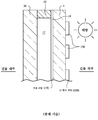
도 1은 종래 기술의 IG 윈도우 유닛의 단면도이다.
도 2는 본 발명의 예시적인 실시예에 따른 IG 윈도우 유닛의 단면도이다.
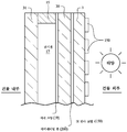
도 3은 본 발명의 다른 예시적인 실시예에 따른 IG 윈도우 유닛의 단면도이다.
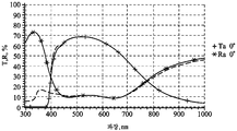
도 4는 라미네이팅된 유리 기판들이 공기 갭의 (윈도우가 제공되도록 의도되는 건물의 외부에 가장 가까운) 외측 면에 있는 본 발명의 도 3의 실시예의 예시적인 IG 윈도우 유닛에 대한 투과율 및 반사율을 파장(nm)의 함수로서 도시한 파장(nm) 대 투과율(T)(%) 및 반사율(R)(%)이며, 여기에서 파선은 UV 반사 코팅이 없는 영역에서의 스펙트럼 곡선이고, 실선은 UV 반사 코팅을 갖는 영역에서의 스펙트럼 곡선이며, 이때 예를 들어 6mm 두께의 유리 기판, 12mm 두께의 공기 갭, 및 약 0.76mm 두께의 PVB 라미네이팅 필름을 가정한다.
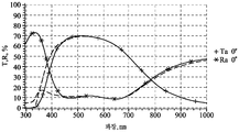
도 5는 라미네이팅된 유리 기판들이 공기 갭의 (윈도우가 제공되도록 의도되는 건물의 내부에 가장 가까운) 내측 면에 있는 본 발명의 도 2의 실시예의 예시적인 IG 윈도우 유닛에 대한 투과율 및 반사율을 파장(nm)의 함수로서 도시한 파장(nm) 대 투과율(T)(%) 및 반사율(R)(%)이며, 여기에서 파선은 UV 반사 코팅이 없는 영역에서의 스펙트럼 곡선이고, 실선은 UV 반사 코팅을 갖는 영역에서의 스펙트럼 곡선이며, 이때 예를 들어 6mm 두께의 유리 기판, 12mm 두께의 공기 갭, 및 약 0.76mm 두께의 PVB 라미네이팅 필름을 가정한다.
도 6은 라미네이팅된 유리 기판들을 갖지 않는 종래 기술의 도 1의 예시적인 IG 윈도우 유닛에 대한 투과율 및 반사율을 파장(nm)의 함수로서 도시한 파장(nm) 대 투과율(T)(%) 및 반사율(R)(%)이며, 여기에서 파선은 UV 반사 코팅이 없는 영역에서의 스펙트럼 곡선이고, 실선은 UV 반사 코팅을 갖는 영역에서의 스펙트럼 곡선이며, 이때 예를 들어 6mm 두께의 유리 기판, 및 12mm 두께의 공기 갭을 가정한다.
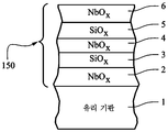
도 7은 본 발명의 예시적인 실시예에 따른, 도 2 및 도 3 중 임의의 것의 IG 윈도우 유닛에 사용될 수 있는, 유리 기판 상의 UV 반사 코팅의 단면도이다.
도 8은 본 발명의 예시적인 실시예에 따른, 도 2 및 도 3 중 임의의 것의 IG 윈도우 유닛에 사용될 수 있는, 유리 기판 상의 다른 UV 반사 코팅의 단면도이다.
도 9는 본 발명의 예시적인 실시예에 따른, 도 2 및 도 3 중 임의의 것의 IG 윈도우 유닛에 사용될 수 있는, 유리 기판 상의 다른 UV 반사 코팅의 단면도이다.
도 10은 본 발명의 예시적인 실시예에 따른, 도 2 및 도 3 중 임의의 것의 IG 윈도우 유닛에 사용될 수 있는, 유리 기판 상의 또 다른 UV 반사 코팅의 단면도이다.
도 11은 본 발명의 예시적인 실시예에 따른, 도 2 및 도 3 중 임의의 것의 IG 윈도우 유닛에 사용될 수 있는, 유리 기판 상의 또 다른 UV 반사 코팅의 단면도이다.1 is a cross-sectional view of a prior art IG window unit.
2 is a cross-sectional view of an IG window unit according to an exemplary embodiment of the present invention.
3 is a cross-sectional view of an IG window unit according to another exemplary embodiment of the present invention.
FIG. 4 shows the transmittance and reflectance wavelengths for the exemplary IG window unit of the embodiment of FIG. 3 of the present invention where the laminated glass substrates are on the outer side of the air gap (closest to the exterior of the building where the window is intended to be provided). nm) as shown as a function of wavelength (nm) versus transmittance (T) (%) and reflectance (R) (%), where the dashed line is the spectral curve in the region without UV reflective coating, and the solid line is UV reflective coating It is a spectral curve in the region with, assuming, for example, a 6 mm thick glass substrate, a 12 mm thick air gap, and a PVB laminating film about 0.76 mm thick.
FIG. 5 shows the transmittance and reflectance wavelengths for the exemplary IG window unit of the embodiment of FIG. 2 of the present invention where the laminated glass substrates are on the inner side of the air gap (closest to the interior of the building where the window is intended to be provided). nm) as shown as a function of wavelength (nm) versus transmittance (T) (%) and reflectance (R) (%), where the dashed line is the spectral curve in the region without UV reflective coating, and the solid line is UV reflective coating It is a spectral curve in the region with, assuming, for example, a 6 mm thick glass substrate, a 12 mm thick air gap, and a PVB laminating film about 0.76 mm thick.
FIG. 6 shows the transmittance and reflectance for the exemplary IG window unit of FIG. 1 of the prior art without laminated glass substrates as a function of wavelength (nm) versus wavelength (nm) versus transmittance (T) (%) and reflectance (R) (%), where the dashed line is the spectral curve in the region without the UV reflective coating, and the solid line is the spectral curve in the region with the UV reflective coating, e.g. a 6 mm thick glass substrate, and 12 mm Assume a thick air gap.
7 is a cross-sectional view of a UV reflective coating on a glass substrate, which can be used in the IG window unit of any of FIGS. 2 and 3, according to an exemplary embodiment of the present invention.
8 is a cross-sectional view of another UV reflective coating on a glass substrate, which may be used in the IG window unit of any of FIGS. 2 and 3, according to an exemplary embodiment of the present invention.
9 is a cross-sectional view of another UV reflective coating on a glass substrate, which may be used in the IG window unit of any of FIGS. 2 and 3, according to an exemplary embodiment of the present invention.
10 is a cross-sectional view of another UV reflective coating on a glass substrate, which may be used in the IG window unit of any of FIGS. 2 and 3, according to an exemplary embodiment of the present invention.
11 is a cross-sectional view of another UV reflective coating on a glass substrate, which may be used in the IG window unit of any of FIGS. 2 and 3, according to an exemplary embodiment of the present invention.
이제 더 상세하게, 몇몇 도면에 걸쳐 유사한 도면 부호가 유사한 부분을 나타내는 첨부 도면을 참조한다.Reference is now made in more detail to the accompanying drawings, in which like reference numbers indicate like parts throughout the several views.
조류와 사람의 색각(color vision) 사이의 차이는 상당하다. 조류의 시각 수용체는 약 370nm일 수 있으며, 이는 조류가 대체적으로 UV 범위에서 효율적으로 볼 수 있음을 의미한다. 이러한 차이를 사용하여, 사람의 눈에 실질적으로 중립적이거나/보이지 않으면서 UV를 효율적으로 반사하는 코팅(그를 조류에게 보이게 함)을 제조하는 것이 가능하다. 따라서, UV 코팅은 실질적으로 사람에게 보이지 않도록 하기 위해, 맨 유리(bare glass)와 본질적으로 동일하거나 유사한 반사율 특성을 갖도록 설계될 수 있다.The difference between bird and human color vision is significant. The algae's visual receptor may be about 370 nm, which means that algae are generally seen efficiently in the UV range. Using this difference, it is possible to produce a coating that effectively reflects UV (makes him visible to birds) without being substantially neutral / visible to the human eye. Thus, the UV coating can be designed to have reflectivity characteristics that are essentially the same as or similar to bare glass to make it substantially invisible to humans.
윈도우는 그와의 조류 충돌을 방지하거나 감소시키도록 설계된다. 소정의 예시적인 실시예에서, 윈도우는 그와의 조류 충돌을 방지하거나 감소시키도록 설계되는 단열 유리(IG) 윈도우 유닛을 포함할 수 있다. IG 윈도우 유닛은 서로 이격되는 적어도 제1 기판(예컨대, 유리 기판)(1, 30 또는 31 중 임의의 것), 제2 기판(예컨대, 유리 기판)(1, 30 또는 31 중 다른 것) 및 제3 기판(예컨대, 유리 기판)(1, 30 또는 31 중 또 다른 것)을 포함하며, 여기에서 기판들 중 적어도 하나(예컨대, 도 2 및 도 3에서 기판(1))는 조류가 윈도우를 더 용이하게 볼 수 있도록 자외선(UV) 방사선을 반사하기 위한 UV 반사 코팅(150)을 지지한다. 기판들 중 적어도 2개는 (예컨대, PVB, EVA, 또는 SGP로 제조되거나 그를 포함하는) 중합체 기반 라미네이팅 필름(200)을 통해 서로 라미네이팅된다. 중합체 기반 라미네이팅 필름(200)은, 바람직하게는, UV의 높은 흡수율을 갖는 유형의 것, 예를 들어 350 내지 380nm에서 적어도 80%, 더 바람직하게는 적어도 90%, 그리고 가장 바람직하게는 적어도 95%의 UV 흡수율을 갖는 필름(200)이다. 이것은 PVB와 같은 라미네이팅 필름의 전형적인 특징이 아니라는 것에 유의하여야 하는데, 이는, 예를 들어 소정의 PVB 필름이 높은 UV 흡수율을 갖지 않기 때문이다(반면에 다른 것들은 그러한 흡수율을 가짐). 예를 들어, 라미네이팅 필름(200)을 통해, 도 2의 실시예에서는 기판(30, 31)이 서로 라미네이팅되고, 도 3의 실시예에서는 기판(1, 30)이 서로 라미네이팅된다. UV 반사 코팅(150)은 바람직하게는 그가 IG 윈도우 유닛의 전체에 걸쳐 제공되지 않도록 패턴화된다. 윈도우를 조류에게 더 잘 보이게 함으로써, 조류 충돌 및 조류 사망이 감소될 수 있다. 본 발명의 예시적인 실시예는 UV 반사 코팅을 갖는 영역과 UV 반사 코팅이 없는 영역 사이의 콘트라스트 비를 추가로 증가시키기 위해 라미네이팅된 유리를 갖는 새로운 IGU 구성을 제공한다. 예를 들어, 라미네이팅된 유리에 사용되는 PVB는 300nm 내지 400nm의 UV 파장 중 많은 부분을 흡수하여, 그에 의해 UV 반사 코팅(150)을 갖는 영역과 UV 반사 코팅(150)이 없는 영역 사이의 콘트라스트 비를 증가시킬 수 있다. IG 윈도우 유닛에 라미네이팅 필름(200)을 통해 라미네이팅된 기판을 제공하는 것은 조류 충돌 윈도우에 특히 유리한데, 왜냐하면 그것이 (a) UV 반사 코팅을 갖는 영역과 UV 반사 코팅을 갖지 않는 영역 사이의 IG 윈도우 유닛의 콘트라스트 비를 증가시켜, 그에 의해 윈도우를 조류에게 더 잘 보이게 하고 조류 충돌의 가능성을 감소시키며, (b) IG 윈도우 유닛의 기계적 내구성을 증가시키고, 조류 충돌로 인한 유리 균열의 가능성을 감소시키며, (c) 소정 실시예에서, 2개의 단일 코팅 면 유리 기판이 제공되도록 허용하여, 가공, 제조, 및/또는 운송 동안 코팅 손상의 가능성을 감소시키도록 생산 내구성 및 가공을 개선하기 때문이다.The window is designed to prevent or reduce bird collisions with him. In certain exemplary embodiments, the window may include an insulated glass (IG) window unit designed to prevent or reduce algal impact therewith. The IG window unit includes at least a first substrate (eg, a glass substrate) spaced apart from each other (any of 1, 30, or 31), a second substrate (eg, glass substrate) (whichever is 1, 30, or 31) and a first 3 substrate (e.g., a glass substrate) (another one of 1, 30 or 31), wherein at least one of the substrates (e.g.,
예를 들어 도 2 및 도 3을 참조하면, 소정의 예시적인 실시예에서, 한 쌍의 이격된 기판들이 적어도 하나의 시일 및/또는 스페이서(15)에 의해 서로 분리될 수 있다. 소정의 예시적인 실시예에서, 윈도우를 조류에게 더 잘 보이게 하여서 충돌을 감소시키기 위해, 적어도 일부 적외선(IR) 방사선을 차단하기 위한 태양광 관리 코팅(예컨대, 저-E 코팅)(19) 및 UV 방사선을 반사하기 위한 UV 반사 차단 코팅(150)이 제공된다. 소정의 예시적인 실시예에서, 저-E 코팅(19)은 0.10 이하의 방사율(En) 및/또는 8 옴/스퀘어 이하의 시트 저항(Rs)을 가질 수 있다. 소정의 예시적인 실시예에서, UV 반사 코팅(19)은 350 내지 440nm의 범위의 적어도 상당 부분에서(또는 대안적으로, 300 내지 400nm의 범위의 상당 부분에서) UV 방사선의 적어도 38%(더 바람직하게는 적어도 40%, 더 바람직하게는 적어도 55%, 훨씬 더 바람직하게는 적어도 60%, 그리고 가능하게는 적어도 65%)를 차단할 수 있다. 이는 상당한 UV 차단율/반사율이며, 예를 들어 그리고 제한 없이, 미국 특허 제8,114,488호에 기재된 코팅에 비해 상당한 이점을 나타낸다. 이는, 그러한 윈도우를 조류에게 더 잘 보이게 하여 그에 의해 조류 충돌을 방지하거나 감소시키기 위해 상업용 또는 주거용 응용을 위해 의도된 윈도우 유닛의 UV 반사율을 증가시킨다. 본 명세서에서의 그러한 코팅의 사용은 스펙트럼의 300 내지 440nm 범위에서 미가공 비코팅 판 유리의 정상 한계를 넘어 UV 반사율을 증가시킴으로써 유리 또는 윈도우의 성능을 향상시킨다. 소정의 예시적인 실시예에서, UV 반사/차단 코팅(150)은 윈도우 유닛 상에 (예컨대, 격자 패턴으로 또는 평행 스트라이프형 패턴으로) 패턴화되는데, 이는 그를 조류에게 훨씬 더 잘 보이게 하여 조류 충돌을 추가로 감소시킬 수 있다. IG 윈도우 유닛은 바람직하게는 적어도 약 50%, 더 바람직하게는 적어도 약 60%, 그리고 훨씬 더 바람직하게는 적어도 약 65% 또는 적어도 약 70%의 가시광선 투과율을 갖는다. 유리 기판(1) 상에 코팅(150)만을 갖는 단일체 코팅된(monolithic coated) 물품(예컨대, 도 3 참조)은: (a) 적어도 약 70%, 더 바람직하게는 적어도 약 80%, 그리고 훨씬 더 바람직하게는 적어도 약 85%의 가시광선 투과율, (b) 적어도 38%(더 바람직하게는 적어도 40%, 더 바람직하게는 적어도 55%, 훨씬 더 바람직하게는 적어도 60%, 그리고 가능하게는 적어도 65%)의 필름측 UV 반사율, 및 (c) 약 20% 미만, 더 바람직하게는 약 15% 미만, 그리고 가장 바람직하게는 약 10% 미만의 필름측 가시광선 반사율을 가질 수 있다. 따라서, 필름측 UV 반사율은 단일체 코팅된 물품의 필름측 가시광선 반사율보다 적어도 약 4배 더 높을 수 있다(더 바람직하게는 적어도 약 5배 더 높을 수 있고, 훨씬 더 바람직하게는 적어도 약 8배 더 높을 수 있으며, 가능하게는 적어도 10배 더 높을 수 있음).For example, referring to FIGS. 2 and 3, in certain exemplary embodiments, a pair of spaced apart substrates may be separated from each other by at least one seal and / or
도 2 및 도 3은 본 발명의 예시적인 실시예에 따른 IG 윈도우 유닛의 일부분의 단면도이다. IG 윈도우 유닛은 유리 기판(1), 유리 기판(30), 및 유리 기판(31)을 포함한다. 도 2의 실시예에서, 유리 기판(1) 및 유리 기판(30)은 적어도 하나 이상의 주변 시일(들) 또는 스페이서(들)(15)에 의해 서로 이격되어, 그들 사이에 공기 갭(17)을 한정한다. UV 반사 코팅(150)은 유리 기판(1)의 외측 면에 제공되고, 저-E 코팅(19)은 기판(1)의 내측 면에 제공된다. 공기 갭은 아르곤 가스와 같은 가스로 충전될 수 있거나 충전되지 않을 수 있다. 선택적으로, 진공 IG 윈도우 유닛의 맥락에서와 같이 기판들을 서로 이격시키기 위해 윈도우의 관찰 영역에서 도 2의 기판들(1, 30) 사이에 스페이서들의 어레이(도시되지 않음)가 제공될 수 있다. 스페이서(들)(15), 다른 스페이서(들), 및/또는 주변 시일은 도 2의 2개의 기판들(1, 30)을 서로 이격시켜서, 기판들이 서로 접촉하지 않도록 그리고 그들 사이에 공간 또는 갭(17)이 한정되도록 한다. 기판들(1, 30) 사이의 공간(17)은 소정의 예시적인 실시예에서 대기압보다 낮은 압력으로 배기 될 수 있고/있거나, 소정의 예시적인 실시예에서 가스(예컨대, Ar)로 충전될 수 있다. 소정의 예시적인 실시예에서, 포일(foil) 또는 다른 방사선 반사 시트(들)(도시되지 않음)를 공간(17) 내에 현수시키는 것이 가능하다. 유리 기판(30, 31)은 도 2의 실시예에서 공기 갭(17)의 내측 면(건물 내부에 가장 가까울 면)에서, 라미네이팅 필름(200)을 통해 서로 라미네이팅된다. 중합체 기반 라미네이팅 필름(17)은 바람직하게는 UV를 흡수하고, 본 발명의 상이한 예시적인 실시예에서 PVB(폴리비닐 부티랄), EVA, SGP(센트리 글래스 플러스(Sentry Glass Plus)) 등으로 제조되거나 그를 포함할 수 있다. 기판(들)(1, 30 및 31)이 유리로 제조될 때, 각각의 유리 기판은 소다-석회-실리카 유형의 유리, 또는 임의의 다른 적합한 유형의 유리로 제조될 수 있고, 본 발명의 소정의 예시적인 실시예에서 두께가 예를 들어 약 1 내지 10mm일 수 있다.2 and 3 are cross-sectional views of a portion of an IG window unit according to an exemplary embodiment of the invention. The IG window unit includes a
유사하게, 도 3의 실시예에서, 유리 기판(30) 및 유리 기판(31)은 적어도 하나 이상의 주변 시일(들) 또는 스페이서(들)(15)에 의해 서로 이격되어, 그들 사이에 공기 갭(17)을 한정한다. UV 반사 코팅(150)은 건물 외부에 가장 가까운 유리 기판(1)의 외측 면에 제공되고, 저-E 코팅(19)은 기판(30)의 내측 면에 제공된다. 공기 갭(17)은 아르곤 가스와 같은 가스로 충전될 수 있거나 충전되지 않을 수 있다. 선택적으로, 진공 IG 윈도우 유닛의 맥락에서와 같이 기판들을 서로 이격시키기 위해 윈도우의 관찰 영역에서 도 3의 기판들(30, 31) 사이에 스페이서들의 어레이(도시되지 않음)가 제공될 수 있다. 스페이서(들)(15), 다른 스페이서(들), 및/또는 주변 시일은 도 3의 2개의 기판들(30, 31)을 서로 이격시켜서, 기판들이 서로 접촉하지 않도록 그리고 그들 사이에 공간 또는 갭(17)이 한정되도록 한다. 기판들(31, 30) 사이의 공간(17)은 소정의 예시적인 실시예에서 대기압보다 낮은 압력으로 배기될 수 있고/있거나, 소정의 예시적인 실시예에서 가스(예컨대, Ar)로 충전될 수 있다. 소정의 예시적인 실시예에서, 포일 또는 다른 방사선 반사 시트(들)(도시되지 않음)를 공간(17) 내에 현수시키는 것이 가능하다. 도 3의 실시예에서, 유리 기판(1, 30)은 공기 갭(17)의 외측 면(건물 외부에 가장 가까울 면)에서, 중합체 기반 라미네이팅 필름(200)을 통해 서로 라미네이팅된다. 중합체 기반 라미네이팅 필름(17)은 바람직하게는 UV를 흡수하고, PVB, EVA, SGP 등으로 제조되거나 그를 포함할 수 있다. 따라서, 도 2 및 도 3은, 주로, (i) 라미네이팅된 구조체가 도 2에서는 공기 갭(17)의 내측 면에 그리고 저-E 코팅(19)의 내측 면에 제공되지만, 도 3에서는 공기 갭(17) 및 저-E 코팅(19)의 외측 면에 제공된다는 점에서, 그리고 (ii) 도 3이 2개의 단일 코팅 면 유리 기판(1, 30)이 제공되도록 허용하는 구조체를 제공하여, 가공, 제조, 및/또는 운송 동안 코팅 손상의 가능성을 감소시키도록 생산 내구성 및 가공을 개선한다는 점에서 서로 상이하다. 사항 (ii)에 관하여, 도 3에서, 제조 공정에서, 유리 기판(1)은 단지 일면만이 UV 코팅(150)으로 코팅되고, 유리 기판(30)은 단지 일면만이 저-E 코팅(19)으로 코팅된다(라미네이팅 필름(200)은 라미네이팅/접착 목적을 위한 중간층이고, 기판의 표면 상에 스퍼터 침착되거나 달리 침착되는 필름이 아님). 반면에, 도 2의 실시예는 유리 기판(1)의 양면이 코팅되되, 일면이 UV 코팅(150)으로 그리고 타면이 저-E 코팅으로 코팅될 것을 필요로 하며, 이는 가공, 운송, 및/또는 취급 동안 손상의 위험을 증가시킬 수 있다.Similarly, in the embodiment of FIG. 3, the
도 2 및 도 3의 IG 윈도우 유닛은 유리 기판(1)의 내측 면에(도 2) 또는 유리 기판(30)의 내측 면에(도 3) 지지되는 태양광 관리 코팅(19)(예컨대, 저-E 코팅)을 포함할 수 있다. 저-E 코팅(19)은 하나 이상의 층을 포함하지만, 많은 실시예에서 그는 다층 코팅이다. 저-E 코팅(19)은 적어도 제1 유전체 층과 제2 유전체 층 사이에 개재되는 (예컨대, 은 또는 금에 기반하는) 적어도 하나의 IR 반사 층을 포함한다. 저-E 코팅(19)의 하나의 예시적인 기능은 소정량의 IR 방사선을 차단(즉, 반사 및/또는 흡수)하고 그가 건물 내부에 도달하는 것을 방지하는 것이기 때문에, 태양광 관리 코팅(9)은 적어도 하나의 IR 차단(즉, IR 반사 및/또는 흡수) 층을 포함한다. 코팅(19) 내에 존재할 수 있는 예시적인 IR 차단 층(들)은 은(Ag), 니켈-크롬(NiCr), 금(Au), 및/또는 상당량의 IR 방사선을 차단하는 임의의 다른 적합한 재료로 제조되거나 그를 포함한다. 저-E 코팅(19)의 IR 차단 층(들)이 모든 IR 방사선을 차단할 필요는 없고, 단지 그의 상당한 양을 차단할 필요가 있다는 것이 당업자에 의해 인식될 것이다. 소정 실시예에서, 코팅(19)의 각각의 IR 차단 층은 적어도 한 쌍의 유전체 층들 사이에 제공된다. 예시적인 유전체 층은 질화규소, 산화티타늄, 산질화규소, 산화주석, 및/또는 다른 유형의 금속 산화물 및/또는 금속 질화물을 포함한다. 소정 실시예에서, 한 쌍의 유전체 층들 사이에 있는 것에 더하여, 각각의 IR 차단 층은 또한, 니켈-크롬의 산화물 및/또는 질화물과 같은 재료 또는 임의의 다른 적합한 재료로 제조되거나 그를 포함하는 한 쌍의 접촉 층들 사이에 제공될 수 있다. 예시적인 저-E 코팅(19)이, 모두가 본 명세서에 참고로 포함되는, 미국 특허 제7,267,879호, 제6,576,349호, 제7,217,461호, 제7,153,579호, 제5,800,933호, 제5,837,108호, 제5,557,462호, 제6,014,872호, 제5,514,476호, 제5,935,702호, 제4,965,121호, 제5,563,734호, 제6,030,671호, 제4,898,790호, 제5,902,505호, 제3,682,528호에 기재되어 있다. 소정의 예시적인 실시예에서, 선택적인 열 처리(예컨대, 열 템퍼링(thermal tempering) 및/또는 열 굽힘(heat bending)) 전 및/또는 후에, 저-E 코팅(19)은 8 옴/스퀘어 이하, 더 바람직하게는 6 옴/스퀘어 이하, 그리고 가장 바람직하게는 4 옴/스퀘어 이하의 시트 저항(Rs)을 가질 수 있다. 소정 실시예에서, 저-E 코팅(19)은 (선택적인 열 처리 전 및/또는 후에) 0.10 이하, 더 바람직하게는 0.07 이하, 그리고 훨씬 더 바람직하게는 0.05 이하의 열 처리 후 방사율(En)을 가질 수 있다. 물론, 본 명세서의 태양광 관리 코팅(19)은 이들 특정 코팅으로 제한되지 않으며, 일정량의 IR 방사선을 차단할 수 있는 임의의 다른 적합한 태양광 관리 코팅이 대신 사용될 수 있다. 본 명세서의 태양광 관리 코팅(19)은 스퍼터링, 증착, 및/또는 임의의 다른 적합한 기술을 포함하지만 이에 제한되지 않는 임의의 적합한 방식으로 기판(들)(1 및/또는 30) 상에 침착될 수 있다.The IG window unit of FIGS. 2 and 3 is supported by a solar care coating 19 (eg, low) on the inner side of the glass substrate 1 (FIG. 2) or on the inner side of the glass substrate 30 (FIG. 3). -E coating). The low-
여전히 도 2 및 도 3을 참조하면, IG 윈도우 유닛은 상당량의 UV 방사선을 반사하여 그에 의해 윈도우를 조류에게 더 잘 보이게 하기 위한 UV 반사 코팅(150)을 추가로 포함한다. 코팅(150)은 본 발명의 예시적인 실시예에서 스퍼터 침착될 수 있다. UV 반사 코팅(150)은 예를 들어 그리고 제한 없이, 도 7 내지 도 11에 예시된 UV 반사 코팅들 중 임의의 것일 수 있다. 이는, 그러한 윈도우를 조류에게 더 잘 보이게 하여 그에 의해 조류 충돌을 방지하거나 감소시키기 위해 윈도우 유닛의 UV 반사율을 증가시킨다. 본 명세서에서의 그러한 코팅(150)의 사용은 스펙트럼의 300 내지 440nm 범위에서 미가공 비코팅 판 유리의 정상 한계를 넘어 UV 반사율을 증가시킴으로써 유리 또는 윈도우의 성능을 향상시킨다. 소정의 예시적인 실시예에서, UV 반사 코팅(150)은 그의 외부 표면 상에서 유리 기판(1)과 직접 접촉하며, 저-E 코팅(19)의 일부가 아니다. 특히, 코팅(150) 내에는 IR 반사 층(예컨대, 은 기반, 금 기반, NiCr, 또는 IR 반사 TCO 기반 층)이 없고, 코팅(150)이 제공되는 기판(1)의 면 상에는 IR 반사 층이 없다. 대신에, 임의의 저-E 코팅(예컨대, 저-E 코팅(19) 참조)이 코팅(150)으로부터 기판(1)의 다른 면 상에 또는 대안적으로 기판(30) 상에 제공될 수 있다. 소정의 예시적인 실시예에서, UV 반사 코팅(150)은 350 내지 440nm의 범위의 적어도 상당 부분에서(또는 대안적으로, 300 내지 400nm의 범위의 상당 부분에서) UV 방사선의 적어도 38%(더 바람직하게는 적어도 40%, 더 바람직하게는 적어도 55%, 훨씬 더 바람직하게는 적어도 60%, 그리고 가능하게는 적어도 65%)를 차단할 수 있다.Still referring to FIGS. 2 and 3, the IG window unit further includes a UV
UV 반사 코팅(150)은 도 2 및 도 3에 도시된 바와 같이 기판(1)의 표면 상에 (예컨대, 격자의 형상으로 또는 실질적으로 평행하거나 평행하지 않은 스트라이프로) 패턴화될 수 있거나, 또는 대안적으로, 다른 실시예에서 기판(1)의 실질적으로 전체 표면에 걸쳐 연속적으로 제공될 수 있다. 코팅(150)의 패턴화된 형상은, 예를 들어, 다음과 같이 형성될 수 있다. 코팅(150)이 형성되기 전에 패턴(도시되지 않음)이 기판(1)의 표면 상에 제공되며, 이때 패턴은 궁극적으로 코팅(150)이 없도록 의도되는 영역에 위치된다. 패턴이 형성된 후에, 패턴 위에 기판(1)의 전체 또는 실질적으로 전체 표면에 걸쳐 코팅(150)이 연속적으로 형성된다. 이어서, 패턴은 (그 바로 위에 위치된 코팅(150)의 부분들과 함께) 제거되어 패턴화된 코팅(150)을 생성할 수 있어서, 코팅(150)은 원래 패턴이 침착되지 않았던 기판의 부분들 상에만 남아 있게 된다. 따라서, 패턴화된 코팅(150)이 본 발명의 예시적인 실시예에서 그러한 방식으로 형성될 수 있다. 남아 있는 패턴화된 코팅(150)은 사람의 눈에는 실질적으로 보이지 않지만, 전술된 바와 같이 조류 눈에는 보인다.The UV
본 발명의 소정의 예시적인 실시예에서, 윈도우 유닛(예컨대, 단열 유리(IG) 윈도우 유닛 및/또는 라미네이팅된 윈도우 유닛)은 그와의 조류 충돌을 방지하거나 감소시키도록 설계된다. IG 윈도우 유닛은 서로 이격되는 2개 또는 3개의 기판들(예컨대, 유리 기판들)을 포함할 수 있고, 기판들 중 적어도 하나는 UV 방사선을 반사하기 위한 자외선(UV) 반사 코팅을 지지한다. UV 반사 코팅은 적어도 제1 유전체 층과 제2 유전체 층 사이에 제공되는 적어도 하나의 적외선(IR) 반사 층(예컨대, 은 기반)을 포함하는 저-E 코팅일 수 있거나, 또는 대안적으로, 은, 금 등의 임의의 IR 반사 층(들) 없이 설계되는 코팅일 수 있다. UV 반사 코팅(150)은 (예컨대, 레이저 절제를 통해) 코팅의 일부분을 패턴으로 완전히 또는 부분적으로 제거하는 데 사용되는 레이저(예컨대, 펨토 레이저(femto laser))에 의해 패턴화될 수 있어서, 레이저에 의한 패턴화 후에, 패턴화된 코팅은 윈도우 유닛의 전체에 걸쳐 제공되지 않고/않거나, UV 반사가 윈도우의 상이한 영역에 걸쳐 상이하도록 윈도우 유닛에 걸쳐 UV 반사가 불균일하여, 그에 의해 UV 방사선을 보고 그러한 패턴을 검출할 수 있는 조류에게 윈도우 유닛을 더 잘 보이게 한다. 따라서, 소정의 예시적인 실시예에서, 침착된 상태(as-deposited)의 UV 반사 코팅은 레이저에 의해 패턴화되지 않은 영역에서 기판 상에 전체가 남아 있고, 레이저에 의해 패턴화된 영역에 부분적으로 남아 있다. 펨토 레이저는, 그들이 밑에 있는 유리 기판을 손상시킴이 없이 그러한 UV 반사 코팅(150)을 효율적으로 패턴화할 수 있고, UV 반사 코팅의 패턴화된 영역 및 비-패턴화된 영역 둘 모두에서 실질적으로 동일한 표면 에너지를 유지시키기 위해 패턴화된 영역에서 그러한 코팅의 일부만을 제거하는 데 더 용이하게 사용될 수 있다는 점에서 유리한 것으로 밝혀졌다. 놀랍게도 그리고 예기치 않게, 펨토 레이저의 사용자가 비-펨토 레이저가 사용된 경우보다 작은 탁도를 갖는 최종 제품을 생성하는 것으로 또한 밝혀졌다. 본 발명의 바람직한 예시적인 실시예에서, 패턴화된 영역 및 비패턴화된 영역 둘 모두를 포함하는 최종 코팅된 물품은 0.4 이하, 더 바람직하게는 0.3 이하, 그리고 가장 바람직하게는 0.2 이하의 탁도 값을 갖는다. 더 작은 탁도는 사람에게 더 미적으로 보기 좋으며, 윈도우를 조류에게 더 잘 보이게 함으로써, 조류 충돌 및 조류 사망이 감소될 수 있다. 놀랍게도, 그리고 예기치 않게, 패턴화 동안, 0.01 내지 2J/㎠, 그리고 가장 바람직하게는 0.05 내지 1J/㎠의 레이저 플루언스(laser fluence)가 유리하게는 패턴화된 영역의 더 매끄러운 절제를 가져오고, 그 절제가 부분적인 코팅 제거와 함께 그러나 유리 기판에 대한 임의의 상당한 손상 없이 그리고 패턴화된 영역에서의 상당한 탁도 없이 행해지도록 허용하는 것으로 또한 밝혀졌다. 패턴화된 UV 반사 코팅(150)은 바람직하게는 가시 범위에서 실질적으로 중립적이어서, UV 코팅의 패턴화는 합리적으로는 사람에 의해 육안을 통해 보이지 않는다. 레이저의 다른 이점은 상황에 맞춰(on the fly) 무작위 패턴화를 할 수 있다는 것이다. 본 발명의 예시적인 실시예에서, 조류 충돌을 감소시키기 위한 윈도우를 제조하는 방법이 제공되는데, 이때 윈도우는 제1 유리 기판 및 적어도 제1 유리 기판에 의해 지지되는 자외선(UV) 반사 코팅을 포함하고, 본 방법은 제1 유리 기판 및 적어도 제1 유리 기판에 의해 지지되는 자외선(UV) 반사 코팅을 갖는 단계; 및 적어도 하나의 레이저원으로부터 레이저 빔을 방출하는 단계 - 레이저 빔은 (i) 1000 펨토초 미만의 지속시간 및/또는 (ii) 0.01 내지 2.0J/㎠의 플루언스를 갖는 광학 펄스를 포함함 - 를 포함하며, 여기에서 광학 펄스를 포함하는 레이저 빔은 UV 반사 코팅에 입사하고, UV 반사 코팅을 상이한 각각의 UV 반사율을 갖는 패턴화된 영역 및 비-패턴화된 영역으로 패턴화하며, 이때 레이저 빔은 패턴화된 영역에 입사하였지만 비-패턴화된 영역에는 입사하지 않았다. 레이저 빔은 100 펨토초 미만의 지속시간, 및 가능하게는 50 펨토초 미만의 지속시간을 갖는 광학 펄스를 포함할 수 있다. UV 반사 코팅의 모든 층은 유전체 층일 수 있거나, 또는 대안적으로, UV 반사 코팅은 적어도 제1 유전체 층과 제2 유전체 층 사이에 개재되는 적어도 하나의 IR 반사 층을 갖는 저-E 코팅일 수 있다.In certain exemplary embodiments of the present invention, window units (eg, insulated glass (IG) window units and / or laminated window units) are designed to prevent or reduce bird strikes therewith. The IG window unit may include two or three substrates spaced apart from each other (eg, glass substrates), and at least one of the substrates supports an ultraviolet (UV) reflective coating to reflect UV radiation. The UV reflective coating can be a low-E coating comprising at least one infrared (IR) reflective layer (eg, silver based) provided between at least the first dielectric layer and the second dielectric layer, or alternatively, silver , Gold, or any other IR reflective layer (s). The UV
도 4 내지 도 6은 도 1의 그것과 비교하여 도 2 및 도 3의 IG 윈도우 유닛과 연관된 놀라운 기술적 이점을 보여주며, 또한 도 2의 실시예(내측 라미네이팅된 구조체)와 비교하여 도 3의 실시예(외측 라미네이팅된 구조체)의 놀라운 기술적 이점을 보여준다. 도 4는 라미네이팅된 유리 기판들이 공기 갭의 (윈도우가 제공되도록 의도되는 건물의 외부에 가장 가까운) 외측 면에 있는 본 발명의 도 3의 실시예의 예시적인 IG 윈도우 유닛에 대한 투과율 및 반사율을 파장(nm)의 함수로서 도시한 파장(nm) 대 투과율(T)(%) 및 반사율(R)(%)이며, 여기에서 파선은 UV 반사 코팅이 없는 영역에서의 스펙트럼 곡선이고, 실선은 UV 반사 코팅을 갖는 영역에서의 스펙트럼 곡선이며, 이때 예를 들어 6mm 두께의 유리 기판, 12mm 두께의 공기 갭, 및 약 0.76mm 두께의 PVB 라미네이팅 필름을 가정한다. 유사한 방식으로, 도 5는 라미네이팅된 유리 기판들이 공기 갭의 (윈도우가 제공되도록 의도되는 건물의 내부에 가장 가까운) 내측 면에 있는 본 발명의 도 2의 실시예의 예시적인 IG 윈도우 유닛에 대한 투과율 및 반사율을 파장(nm)의 함수로서 도시한 파장(nm) 대 투과율(T)(%) 및 반사율(R)(%)이며, 여기에서 파선은 UV 반사 코팅이 없는 영역에서의 스펙트럼 곡선이고, 실선은 UV 반사 코팅을 갖는 영역에서의 스펙트럼 곡선이며, 이때 예를 들어 6mm 두께의 유리 기판, 12mm 두께의 공기 갭, 및 약 0.76mm 두께의 PVB 라미네이팅 필름을 가정한다. 비교를 위해, 도 6은 라미네이팅된 유리 기판들을 갖지 않는 종래 기술의 도 1의 예시적인 IG 윈도우 유닛에 대한 투과율 및 반사율을 파장(nm)의 함수로서 도시한 파장(nm) 대 투과율(T)(%) 및 반사율(R)(%)이며, 여기에서 파선은 UV 반사 코팅이 없는 영역에서의 스펙트럼 곡선이고, 실선은 UV 반사 코팅을 갖는 영역에서의 스펙트럼 곡선이며, 이때 예를 들어 6mm 두께의 유리 기판, 및 12mm 두께의 공기 갭을 가정한다. 동일한 저-E 코팅이 도 4 내지 도 6의 각각에서 가정되고, 동일한 UV 반사 코팅이 도 4 및 도 5의 각각에서 가정된다. 따라서, 도 4는 도 3의 실시예의 일례에 대응하고, 도 5는 도 2의 실시예의 일례에 대응하며, 도 6은 종래 기술의 도 1에 대응한다.4 to 6 show surprising technical advantages associated with the IG window unit of FIGS. 2 and 3 compared to that of FIG. 1, and also the implementation of FIG. 3 compared to the embodiment of FIG. 2 (inner laminated structure). It shows the surprising technical advantage of the example (outside laminated structure). FIG. 4 shows the transmittance and reflectance wavelengths for the exemplary IG window unit of the embodiment of FIG. 3 of the present invention where the laminated glass substrates are on the outer side of the air gap (closest to the exterior of the building where the window is intended to be provided). nm) as shown as a function of wavelength (nm) versus transmittance (T) (%) and reflectance (R) (%), where the dashed line is the spectral curve in the region without the UV reflective coating, and the solid line is the UV reflective coating. It is a spectral curve in the region with, assuming, for example, a 6 mm thick glass substrate, a 12 mm thick air gap, and a PVB laminating film about 0.76 mm thick. In a similar manner, FIG. 5 shows transmittance for the exemplary IG window unit of the embodiment of FIG. 2 of the present invention where the laminated glass substrates are on the inner side of the air gap (closest to the interior of the building where the window is intended to be provided) and The wavelength (nm) vs. transmittance (T) (%) and reflectance (R) (%) showing the reflectance as a function of wavelength (nm), where the dashed line is the spectral curve in the region without UV reflective coating, and the solid line Is a spectral curve in the region with a UV reflective coating, assuming, for example, a 6 mm thick glass substrate, a 12 mm thick air gap, and a PVB laminating film about 0.76 mm thick. For comparison, FIG. 6 shows the transmittance and reflectance as a function of wavelength (nm) versus transmittance (T) for the exemplary IG window unit of FIG. 1 of the prior art without laminated glass substrates ( %) And reflectance (R) (%), where the dashed line is the spectral curve in the region without the UV reflective coating, and the solid line is the spectral curve in the region with the UV reflective coating, for example 6 mm thick glass Assume a substrate, and a 12 mm thick air gap. The same low-E coating is assumed in each of FIGS. 4-6, and the same UV reflective coating is assumed in each of FIGS. 4 and 5. Accordingly, FIG. 4 corresponds to an example of the embodiment of FIG. 3, FIG. 5 corresponds to an example of the embodiment of FIG. 2, and FIG. 6 corresponds to FIG. 1 of the prior art.
도 4 및 도 5에서, 실선 투과율 곡선(Ta)이 도 6에서보다 훨씬 더 오랫동안 UV 영역에서 평평하게 유지되는 것을 볼 수 있다. 특히, 도 6에서, 투과율 곡선은 약 335nm에서 증가하기 시작하는 반면에, 도 4 내지 도 5에서, 투과율 곡선은 380nm 후까지 증가하기 시작하지 않으며, 그에 의해 도 2 및 도 3의 라미네이팅된 구조체가 라미네이팅된 구조체를 갖지 않는 종래 기술의 도 1의 구조체보다 훨씬 더 우수하게 300 내지 400nm의 UV 영역에서 투과율을 억제하는 것을 보여준다. 이것이 UV 방사선을 흡수하는 라미네이팅 필름(200)의 존재 때문일 수 있는 것이 가능하다.In FIGS. 4 and 5, it can be seen that the solid line transmittance curve Ta remains flat in the UV region for much longer than in FIG. 6. In particular, in FIG. 6, the transmittance curve starts to increase at about 335 nm, while in FIGS. 4 to 5, the transmittance curve does not start to increase until after 380 nm, whereby the laminated structures of FIGS. 2 and 3 are It is shown to suppress transmittance in the UV region of 300 to 400 nm much better than the structure of FIG. 1 of the prior art without a laminated structure. It is possible that this may be due to the presence of a
따라서, 도 4 내지 도 6에 도시된 바와 같이, 투과 모드에서, 라미네이션(한 쌍의 기판을 함께 라미네이팅하는 라미네이팅 필름(200)이 존재할 때)은 UV 반사 코팅을 갖는 영역 및 UV 반사 코팅이 없는 영역 둘 모두에 대한 UV 투과율을 감소시켜, 그에 의해 UV 코팅이 없을 때의 투과율 대 UV 코팅이 있을 때의 투과율의 비로 정의되는 투과 콘트라스트 비 CR(TR)을 향상시킨다.Therefore, as shown in FIGS. 4 to 6, in the transmission mode, the lamination (when the
![]()
![]()
콘트라스트 비는 (도 1에 비해) 약 365 내지 369nm에서 도 2 및 도 3의 라미네이팅된 IGU에 대해 더 높은 것으로 밝혀졌다. 내측 라미네이팅된 구조체 및 외측 라미네이팅된 구조체에 대한 투과율 곡선은 거의 동일하여, 도 2 및 도 3의 실시예에 대한 투과 모드에서는 개선이 본질적으로 동일하다.The contrast ratio was found to be higher for the laminated IGU of FIGS. 2 and 3 at about 365 to 369 nm (compared to FIG. 1). The transmittance curves for the inner laminated structure and the outer laminated structure are almost the same, so the improvement is essentially the same in the transmission mode for the embodiments of FIGS. 2 and 3.
반면에, 외측 라미네이팅된 구조체를 갖는 도 3의 IG 유닛이 도 1 및 도 2의 IG 유닛 둘 모두와 비교하여 개선된 성능 특징을 실현하는 것으로 밝혀졌다. 이는 도 3이 (도 1에 비해) 라미네이팅된 구조체를 갖기 때문이고, 도 3이 (도 2에 비해) 그러한 라미네이팅된 구조체를 공기 갭 및 저-E 코팅의 외측 면에 갖기 때문이다. 도 4 내지 도 6은 도 1 내지 도 3의 IG 유닛이 UV 스펙트럼에서 매우 상이한 반사율 곡선을 갖는 것을 보여준다. 도 3의 외측 라미네이팅된 구조체의 경우에는, 태양으로부터의 UV 광은 그가 저-E 코팅(19)에 도달하기 전에 PVB(200)에 의해 대부분 흡수된다. 그러나, 도 2의 내측 라미네이팅된 구조체의 경우에는, UV 광의 소정 부분이 저-E 코팅(19)에 도달하여 그에 의해 반사되며; 이러한 양의 추가의 UV 반사는 UV 코팅(150)을 갖는 영역 대 UV 코팅(150)이 없는 영역에서의 반사율의 비로 정의되는 반사 콘트라스트 비 CR(RF)을 감소시킨다.On the other hand, it has been found that the IG unit of FIG. 3 with the outer laminated structure realizes improved performance characteristics compared to both of the IG units of FIGS. 1 and 2. This is because FIG. 3 has a laminated structure (compared to FIG. 1), and FIG. 3 has a laminated structure (compared to FIG. 2) on the outer side of the air gap and low-E coating. 4 to 6 show that the IG units of FIGS. 1 to 3 have very different reflectance curves in the UV spectrum. In the case of the outer laminated structure of FIG. 3, UV light from the sun is mostly absorbed by the
![]()
![]()
따라서, 공기 갭(17)의 외측 면에 그리고 저-E 코팅(19)의 외측 면에 라미네이팅된 구조체를 제공하는 것으로 인해, IG 유닛의 반사 콘트라스트 비가 놀랍게도 본 발명의 도 2의 실시예와 비교하여, 본 발명의 도 3의 실시예에 대해 상당히 더 높은 것으로 밝혀졌으며, 그에 따라서 도 3의 IG 윈도우 유닛이 조류에게 더 잘 보일 것이며, 그에 따라서 도 1 및 도 2의 실시예 둘 모두보다 적은 조류 충돌을 실현할 것이다.Thus, by providing a laminated structure on the outer side of the
도 7 내지 도 11은 본 발명의 예시적인 실시예에서, 도 1 또는 도 2의 IG 윈도우 유닛 내의 기판(1) 상에 사용될 수 있는 다양한 UV 반사 코팅(150)의 단면도들이다. 유리 기판(1)은 본 발명의 예시적인 실시예에서, 소다-석회-실리카계 유리 또는 임의의 다른 적합한 유형의 유리일 수 있고, 약 1 내지 10mm의 두께, 더 바람직하게는 약 2 내지 6mm의 두께일 수 있다.7-11 are cross-sectional views of various UV
도 7의 실시예에서, UV 반사 코팅(150)은 산화니오븀(예컨대, Nb2O5, NbO2 및/또는 NbO)으로 제조되거나 그를 포함하는 고 굴절률 투명 유전체 층(2, 4, 6), 및 산화규소(예컨대, 알루미늄 및/또는 질소로 도핑될 수 있거나 도핑되지 않을 수 있는 SiO2)로 제조되거나 그를 포함하는 저 굴절률 투명 유전체 층(3, 5)을 포함한다. 도 7의 층(6)은 선택적이고, 소정 경우에 UV 반사율을 개선하기 위해 제거될 수 있거나, 대신에 산화지르코늄으로 제조되거나 그를 포함할 수 있다는 것에 유의하여야 한다. 소정의 예시적인 실시예에서, 산화규소 층들(3 및/또는 5) 중 하나 또는 둘 모두는 약 1 내지 8%의 알루미늄 및/또는 약 1 내지 10%의 질소와 같은 다른 재료로 도핑될 수 있다. 소정의 예시적인 경우에, 층들(2, 4, 6) 중 하나 이상이 또한 다른 재료로 도핑될 수 있다. 도 7의 실시예에서, 층(6)은 코팅(150)의 최외부 층이고, 공기에 노출될 수 있다. 층들(2 내지 6) 각각은 가시 광에 대해 "투명한" 것으로 간주되는데, 왜냐하면 독립형인 이들 층 각각이 가시 광에 대해 실질적으로 투명(예컨대, 가시 광에 대해 적어도 약 50% 투명, 더 바람직하게는 적어도 약 60% 또는 70% 투명)하기 때문이다. 산화니오븀으로 제조되거나 그를 포함하는 고 굴절률 투명 유전체 층들(2, 4, 6)은 (550nm에서) 약 2.15 내지 2.5, 더 바람직하게는 약 2.2 내지 2.4, 그리고 가장 바람직하게는 약 2.25 내지 2.35의 굴절률(n)을 가질 수 있다. 소정의 대안적인 실시예에서, 산화니오븀은 하나 이상의 고 굴절률 층들(2, 4 및/또는 6)에서 산화티타늄(예컨대, TiO2), 산화지르코늄, 산화하프늄(예컨대, HfO2), 산화세륨(예컨대, CeO2), 황화 아연, 또는 산화비스무트(예컨대, Bi2O3)로 대체될 수 있다. 따라서, 하나의 그러한 예에서, 층(6)은 산화티타늄으로 제조되거나 그를 포함할 수 있는 한편, 층들(2, 4)은 산화니오븀으로 제조되거나 그를 포함하고, 층들(3, 5)은 산화규소로 제조되거나 그를 포함한다. 산화규소로 제조되거나 그를 포함하는 저 굴절률 투명 유전체 층들(3, 5)은 약 1.4 내지 1.7, 더 바람직하게는 약 1.4 내지 1.6, 그리고 가장 바람직하게는 약 1.45 내지 1.55의 굴절률(n)을 가질 수 있다(본 명세서의 모든 굴절률(n) 값들은 550nm에서 측정됨). 투명 유전체 층들(2 내지 6)은, 바람직하게는, 본 발명의 예시적인 실시예에서 스퍼터링에 의해 침착된다. 예를 들어, 산화니오븀으로 제조되거나 그를 포함하는 투명 유전체 층들(2, 4, 6)은 아르곤과 반응성 산소 가스의 혼합물을 포함하는 분위기에서 스퍼터링을 통해, Nb로 제조되거나 Nb를 포함하는 적어도 하나의 스퍼터링 타깃을 통해 스퍼터 침착될 수 있다. 또한 예를 들어, 산화규소로 제조되거나 그를 포함하는 투명 유전체 층들(3, 5)은 아르곤과 반응성 산소 가스의 혼합물을 포함하는 분위기에서 스퍼터링을 통해, Si 또는 SiAl로 제조되거나 그를 포함하는 적어도 하나의 스퍼터링 타깃을 통해 스퍼터 침착될 수 있다. 회전 C-Mag 스퍼터링 타깃, 또는 다른 유형의 타깃이 사용될 수 있다. 스퍼터링 작업에서, 충분한 반응성 산소 가스가 본 명세서에서 논의된 굴절률 값들을 달성하기 위해 사용될 수 있다. 세라믹 타깃이, 대안적으로, 이들 층 중 하나 이상을 스퍼터 침착시키기 위해 사용될 수 있다. 층들(2 내지 6)이 바람직하게는 스퍼터링을 통해 침착되지만, 그들은 본 발명의 대안적인 실시예에서 다른 기술을 통해 침착될 수 있는 것이 가능하다. 도 7의 실시예에서 코팅(150)이 5개의 층으로 구성되지만, 대안적인 실시예에서는 추가의 층이 제공될 수 있는 것이 가능하다. 예를 들어, 산화지르코늄으로 제조되거나 그를 포함하는 보호 층(도시되지 않음)이 층(6) 위에 있는 그리고 그와 직접 접촉하는 최상부 층으로서 코팅(150) 내에 제공될 수 있다. 도 7의 실시예 및 다른 예시적인 실시예의 코팅(150)은 금속 반사 층을 포함하지 않는다.In the embodiment of FIG. 7, UV
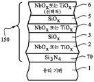
도 8은 도 2 또는 도 3의 IG 윈도우 유닛 내의 기판(1) 상에 사용될 수 있는 다른 UV 반사 코팅(150)의 단면도이다. 도 8의 실시예는 투명 유전체 장벽 층(70)이 유리 기판(1)과 고 굴절률 층(2) 사이에 제공되는 것을 제외하고는, 도 7의 실시예와 동일하다. 도 8의 층(6)은 선택적이고, 소정 경우에 UV 반사율을 개선하기 위해 제거될 수 있거나, 대신에 산화지르코늄으로 제조되거나 그를 포함할 수 있다는 것에 유의하여야 한다. 장벽 층(70)은, 본 발명의 소정의 예시적인 실시예에서, 질화규소(예컨대, Si3N4)로 제조되거나 그를 포함한다. 장벽 층(70)은 선택적으로 도 7 내지 도 11 중 임의의 것의 코팅에 사용될 수 있지만, 간략함을 위해 도 8에만 도시되어 있다. 소정의 예시적인 실시예에서, 질화규소 기반 장벽 층(70)은 약 1 내지 8%의 알루미늄 및/또는 약 1 내지 10%의 산소와 같은 다른 재료로 도핑될 수 있다. 도 8의 실시예는 열 처리된(예컨대, 열 템퍼링된) 실시예에 특히 유용하며, 여기에서 장벽 층(70)은 고온 열 처리 동안 유리 기판으로부터 코팅 내로의 원소(예컨대, Na)의 이동을 방지하거나 감소시키는 데 도움을 준다. 그러한 열 처리(예컨대, 열 템퍼링)는, 예를 들어, 코팅된 물품을 적어도 약 580℃, 더 바람직하게는 적어도 약 600℃의 온도(들)에서 오븐 등 내에서 가열하는 것을 포함할 수 있다. 도 8의 실시예의 코팅은, 본 발명의 예시적인 실시예에서, 열 처리될(예컨대, 열 템퍼링될) 수 있거나 열 처리되지 않을 수 있다.8 is a cross-sectional view of another UV
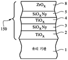
도 9는 도 2 또는 도 3의 IG 윈도우 유닛 내의 기판(1) 상에 사용될 수 있는 다른 UV 반사 코팅(150)의 단면도이다. 도 9의 실시예는 층(6)이 제거된 것을 제외하고는, 도 7의 실시예와 동일하다. 도 9에 도시된 코팅된 물품은, 예를 들어, 약 40 내지 45%의 필름측 UV 반사율을 가질 수 있으며, 이때 일례는 약 41%이다(300 내지 400nm의 범위의 적어도 상당 부분에서 적어도 이러한 많은 UV 방사선을 반사함). 도 9의 실시예의 일례에서, 층(5)은 UV 반사 코팅(150)의 최외부 층이고, 층(2)은 산화티타늄(예컨대, TiO2)으로 제조되거나 그를 포함하며, 층(3)은 산화규소(예컨대, 알루미늄 및/또는 질소로 도핑될 수 있거나 도핑되지 않을 수 있는 SiO2)로 제조되거나 그를 포함하고, 층(4)은 산화니오븀(예컨대, Nb2O5, NbO2 및/또는 NbO)으로 제조되거나 그를 포함하며, 층(5)은 산화규소(예컨대, 알루미늄 및/또는 질소로 도핑될 수 있거나 도핑되지 않을 수 있는 SiO2)로 제조되거나 그를 포함한다. 선택적으로, 도 9의 실시예의 코팅은 또한, 산화지르코늄(예컨대, ZrO2)으로 제조되거나 그를 포함하는 오버코트(overcoat)를 포함할 수 있다. 본 발명의 도 9의 실시예의 소정의 예시적인 실시예에서, (i) 산화티타늄으로 제조되거나 그를 포함하는 투명 유전체 층(2)은 약 5 내지 40nm의 두께, 더 바람직하게는 약 10 내지 25nm의 두께, 훨씬 더 바람직하게는 약 10 내지 20nm의 두께일 수 있으며, 이때 예시적인 두께는 약 13 내지 16nm이고; (ii) 산화규소로 제조되거나 그를 포함하는 투명 유전체 층(3)은 약 30 내지 100nm의 두께, 더 바람직하게는 약 40 내지 80nm의 두께, 훨씬 더 바람직하게는 약 50 내지 70nm의 두께일 수 있으며, 이때 예시적인 두께는 약 60nm이고; (iii) 산화니오븀으로 제조되거나 그를 포함하는 투명 유전체 층(4)은 약 15 내지 150nm의 두께, 더 바람직하게는 약 20 내지 125nm의 두께, 훨씬 더 바람직하게는 약 95 내지 120nm의 두께일 수 있으며, 이때 예시적인 두께는 약 33nm 또는 약 105nm이고; (iv) 산화규소로 제조되거나 그를 포함하는 투명 유전체 층(5)은 약 40 내지 130nm의 두께, 더 바람직하게는 약 50 내지 110nm의 두께, 훨씬 더 바람직하게는 약 60 내지 100nm의 두께일 수 있으며, 이때 예시적인 두께는 약 60nm 또는 약 90nm이고; (v) 산화지르코늄으로 제조되거나 그를 포함하는 선택적인 투명 오버코트 보호 유전체 층(8)은 약 5 내지 60nm의 두께, 더 바람직하게는 약 5 내지 30nm의 두께, 훨씬 더 바람직하게는 약 5 내지 20nm의 두께일 수 있으며, 이때 예시적인 두께는 약 10nm이다. 본 명세서에서 원하는 UV 반사율 및 가시광선 투과율 값들을 실현하기 위해, 산화니오븀 기반 층(4)은, 바람직하게는, 산화티타늄 기반 층(2)보다 실질적으로 더 두껍다. 예를 들어, 소정의 예시적인 실시예에서, 산화니오븀 기반 층(4)은 산화티타늄 기반 층(2)보다 적어도 약 40nm 더 두껍다(더 바람직하게는 적어도 약 50nm 더 두껍고, 가장 바람직하게는 적어도 약 70nm 더 두꺼움). 더욱이, 산화니오븀 기반 층(4)은 또한, 바람직하게는 층들(3, 5) 각각보다 더 두꺼운데, 예를 들어, 층(4)은 산화규소 기반 층들(3, 5) 각각보다 적어도 약 10nm 더 두껍고, 가장 바람직하게는 적어도 약 15nm 더 두껍다. 산화규소 기반 층(5)은 본 발명의 도 2, 도 3, 도 9의 실시예의 소정 실시예에서 산화규소 기반 층(3)보다 적어도 약 10 또는 20nm 더 두껍다. 선택적으로, 산화지르코늄으로 제조되거나 그를 포함하는 보호 층(도시되지 않음)이 (도 10의 보호 외부 층과 유사하게) 도 9의 코팅 내의 층(5) 위에 최외부 층으로서 제공될 수 있다.9 is a cross-sectional view of another UV
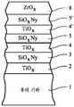
도 10은 도 2 또는 도 3의 IG 윈도우 유닛 내의 기판(1) 상에 사용될 수 있는 다른 UV 반사 코팅(150)의 단면도이다. 도 10에 도시된 코팅된 물품은, 예를 들어, 약 60 내지 70%의 필름측 UV 반사율을 가질 수 있으며, 이때 일례는 약 65%이다(300 내지 400nm의 범위의 적어도 상당 부분에서 적어도 이러한 많은 UV 방사선을 반사함). 도 10의 실시예의 일례에서, 층(2)은 산화티타늄(예컨대, TiO2)으로 제조되거나 그를 포함하고, 층들(3, 5)은 산질화규소(예컨대, 이는 알루미늄으로 도핑될 수 있거나 도핑되지 않을 수 있음)로 제조되거나 그를 포함하며, 층(4)은 산화티타늄(예컨대, TiO2)으로 제조되거나 그를 포함하고, 최외부 보호 층(8)은 산화지르코늄(예컨대, ZrO2)으로 제조되거나 그를 포함한다. 본 발명의 도 10의 실시예의 소정의 예시적인 실시예에서, (i) 산화티타늄으로 제조되거나 그를 포함하는 투명 유전체 층(2)은 약 5 내지 40nm의 두께, 더 바람직하게는 약 10 내지 25nm의 두께, 훨씬 더 바람직하게는 약 10 내지 20nm의 두께일 수 있으며, 이때 예시적인 두께는 약 17nm이고; (ii) 산질화규소로 제조되거나 그를 포함하는 투명 유전체 층(3)은 약 30 내지 100nm의 두께, 더 바람직하게는 약 40 내지 80nm의 두께, 훨씬 더 바람직하게는 약 45 내지 70nm의 두께일 수 있으며, 이때 예시적인 두께는 약 50nm이고; (iii) 산화티타늄으로 제조되거나 그를 포함하는 투명 유전체 층(4)은 약 10 내지 80nm의 두께, 더 바람직하게는 약 15 내지 50nm의 두께, 훨씬 더 바람직하게는 약 20 내지 40nm의 두께일 수 있으며, 이때 예시적인 두께는 약 30nm이고; (iv) 산질화규소로 제조되거나 그를 포함하는 투명 유전체 층(5)은 약 50 내지 130nm의 두께, 더 바람직하게는 약 70 내지 120nm의 두께, 훨씬 더 바람직하게는 약 80 내지 110nm의 두께일 수 있으며, 이때 예시적인 두께는 약 88nm이고; (v) 산화지르코늄으로 제조되거나 그를 포함하는 투명 유전체 보호 층(8)은 약 3 내지 30nm의 두께, 더 바람직하게는 약 4 내지 10nm의 두께일 수 있으며, 이때 예시적인 두께는 약 7nm이다. 본 명세서에서 원하는 UV 반사율 및 가시광선 투과율 값들을 실현하기 위해, 층(4)은, 바람직하게는, 산화티타늄 기반 층(2)보다 실질적으로 더 두껍다. 예를 들어, 소정의 예시적인 실시예에서, 산화티타늄 기반 층(4)은 산화티타늄 기반 층(2)보다 적어도 약 8nm 더 두껍다(더 바람직하게는 적어도 약 10nm 더 두껍고, 가장 바람직하게는 적어도 약 15nm 더 두꺼움). 또한, 산질화규소 기반 층(5)은 본 발명의 도 2, 도 3, 도 10의 실시예의 소정 실시예에서 산질화규소 기반 층(3)보다 적어도 약 10, 20 또는 30nm 더 두껍다.10 is a cross-sectional view of another UV
도 11은 도 2 또는 도 3의 IG 윈도우 유닛 내의 기판(1)의 외측 면에 사용될 수 있는 다른 UV 반사 코팅(150)의 단면도이다. 도 11에 도시된 코팅된 물품은, 예를 들어, 약 50 내지 80%의 필름측 UV 반사율을 가질 수 있으며, 이때 일례는 약 70%이다(300 내지 400nm의 범위의 적어도 상당 부분에서 적어도 이러한 많은 UV 방사선을 반사함). 도 11의 실시예의 일례에서, 층들(2, 4, 4')은 산화티타늄(예컨대, TiO2)으로 제조되거나 그를 포함하고, 층들(3, 5, 5')은 산질화규소(예컨대, 이는 알루미늄으로 도핑될 수 있거나 도핑되지 않을 수 있음)로 제조되거나 그를 포함하며, 최외부 보호 층(8)은 산화지르코늄(예컨대, ZrO2)으로 제조되거나 그를 포함한다. 본 발명의 도 11의 실시예의 소정의 예시적인 실시예에서, (i) 산화티타늄으로 제조되거나 그를 포함하는 투명 유전체 층(2)은 약 5 내지 40nm의 두께, 더 바람직하게는 약 10 내지 25nm의 두께, 훨씬 더 바람직하게는 약 10 내지 20nm의 두께일 수 있으며, 이때 예시적인 두께는 약 11nm이고; (ii) 산질화규소로 제조되거나 그를 포함하는 투명 유전체 층(3)은 약 30 내지 100nm의 두께, 더 바람직하게는 약 40 내지 80nm의 두께, 훨씬 더 바람직하게는 약 45 내지 70nm의 두께일 수 있으며, 이때 예시적인 두께는 약 63nm이고; (iii) 산화티타늄으로 제조되거나 그를 포함하는 투명 유전체 층(4)은 약 10 내지 80nm의 두께, 더 바람직하게는 약 15 내지 50nm의 두께, 훨씬 더 바람직하게는 약 20 내지 40nm의 두께일 수 있으며, 이때 예시적인 두께는 약 37nm이고; (iv) 산질화규소로 제조되거나 그를 포함하는 투명 유전체 층(5)은 약 10 내지 70nm의 두께, 더 바람직하게는 약 15 내지 60nm의 두께, 훨씬 더 바람직하게는 약 20 내지 40nm의 두께일 수 있으며, 이때 예시적인 두께는 약 32nm이고; (v) 산화티타늄으로 제조되거나 그를 포함하는 투명 유전체 층(4')은 약 10 내지 80nm의 두께, 더 바람직하게는 약 15 내지 50nm의 두께, 훨씬 더 바람직하게는 약 20 내지 40nm의 두께일 수 있으며, 이때 예시적인 두께는 약 33nm이고; (vi) 산질화규소로 제조되거나 그를 포함하는 투명 유전체 층(5')은 약 50 내지 130nm의 두께, 더 바람직하게는 약 70 내지 120nm의 두께, 훨씬 더 바람직하게는 약 80 내지 110nm의 두께일 수 있으며, 이때 예시적인 두께는 약 100nm이고; (vii) 기계적 내구성을 위해 산화지르코늄으로 제조되거나 그를 포함하는 투명 유전체 보호 층(8)은 약 3 내지 30nm의 두께, 더 바람직하게는 약 4 내지 10nm의 두께일 수 있으며, 이때 예시적인 두께는 약 5nm이다. 본 명세서에서 원하는 UV 반사율 및 가시광선 투과율 값들을 실현하기 위해, 고 굴절률 층들(4, 4')은, 바람직하게는, 고 굴절률 층(2)보다 실질적으로 더 두껍다. 예를 들어, 소정의 예시적인 실시예에서, 산화티타늄 기반 층들(4, 4')은 고 굴절률 산화티타늄 기반 층(2)보다 적어도 약 8nm 더 두꺼울 수 있다(더 바람직하게는 적어도 약 10nm 더 두껍고, 가장 바람직하게는 적어도 약 15nm 더 두꺼움). 또한, 산질화규소 기반 층(5')은 본 발명의 도 2, 도 3, 도 11의 실시예의 소정 실시예에서 산질화규소 기반 층들(3 및/또는 5)보다 적어도 약 10, 20 또는 30nm 더 두껍다. 도 10 및 도 11의 실시예에서, 산질화규소 기반 층들(3, 5, 5')은 약 1.6 내지 1.8, 더 바람직하게는 약 1.65 내지 1.75, 그리고 가장 바람직하게는 1.7의 굴절률(n)(550nm에서 측정됨)을 가질 수 있다. 도 10 및 도 11의 실시예는 또한 놀랍게도, 그들의 광학적 특성이 코팅되지 않은 플로트 유리(float glass)의 광학적 특성에 근사한 것으로 밝혀졌다는 점에서 유리하며, 이는 코팅(150)을 본질적으로 사람의 눈에 보이지 않게 한다.11 is a cross-sectional view of another UV
본 발명의 예시적인 실시예에서, IG 윈도우 유닛으로서, 제1 유리 기판; 제2 유리 기판; 제3 유리 기판 - 제1 유리 기판은 IG 윈도우 유닛이 장착되도록 의도되는 건물의 외부를 향하도록 IG 윈도우 유닛의 외부 면에 제공되고; 제2 유리 기판은 적어도 제1 유리 기판과 제3 유리 기판 사이에 제공되며; 제3 유리 기판은 IG 윈도우 유닛이 장착되도록 의도되는 건물의 내부를 향하도록 IG 윈도우 유닛의 내부 면에 제공됨 -; IG 윈도우 유닛이 장착되도록 의도되는 건물의 외부를 향하도록 IG 윈도우 유닛의 외부 표면 상에 그리고 제1 유리 기판 상에 제공되는 패턴화된 UV 반사 코팅 - 제1 및 제2 유리 기판들은 중합체 포함 라미네이팅 필름을 통해 서로 라미네이팅됨 -; 및 중합체 포함 라미네이팅 필름 반대편의 제2 유리 기판의 면 상에 제공되어, 제2 유리 기판이 중합체 포함 라미네이팅 필름과의 사이에 위치되는 저-E 코팅을 포함하고; 제1 유리 기판은 패턴화된 UV 반사 코팅과 중합체 포함 라미네이팅 필름 사이에 위치되며; UV 반사 코팅은 저-E 코팅의 일부가 아니고, 은 또는 금의 임의의 IR 반사 층을 포함하지 않으며; 제2 유리 기판은 적어도 공기 갭을 통해 제3 유리 기판으로부터 이격되어, 제1 유리 기판, 제2 유리 기판, 및 중합체 포함 라미네이팅 필름을 포함하는 라미네이팅된 구조체가 공기 갭의 외측 면에 그리고 저-E 코팅의 외측 면에 위치되게 하는, IG 윈도우 유닛이 제공된다.In an exemplary embodiment of the invention, an IG window unit comprising: a first glass substrate; A second glass substrate; Third glass substrate-the first glass substrate is provided on the outer side of the IG window unit so as to face the outside of the building where the IG window unit is intended to be mounted; A second glass substrate is provided between at least the first glass substrate and the third glass substrate; A third glass substrate is provided on the inner side of the IG window unit to face the interior of the building where the IG window unit is intended to be mounted; Patterned UV reflective coating provided on the outer surface of the IG window unit and on the first glass substrate to face the exterior of the building where the IG window unit is intended to be mounted-the first and second glass substrates are polymer-laminated laminating films Laminated to each other through-; And a low-E coating provided on the side of the second glass substrate opposite the polymer containing laminating film, wherein the second glass substrate is positioned between the polymer containing laminating film; The first glass substrate is positioned between the patterned UV reflective coating and the polymer-containing laminating film; The UV reflective coating is not part of the low-E coating and does not include any IR reflective layer of silver or gold; The second glass substrate is at least spaced from the third glass substrate through an air gap such that a laminated structure comprising a first glass substrate, a second glass substrate, and a laminating film comprising a polymer is on the outer side of the air gap and low-E. An IG window unit is provided, which is positioned on the outer side of the coating.
직전 단락의 IG 윈도우 유닛에서, UV 반사 코팅은 제1, 제2, 제3, 및 제4 층들을 제1 유리 기판으로부터 멀어지는 이러한 순서로 포함할 수 있으며, 제1 및 제3 층들은 적어도 약 2.25의 굴절률을 갖는 고 굴절률 층일 수 있고, 제2 및 제4 층들은 1.8 이하의 굴절률을 갖는 저 굴절률 층일 수 있으며, 여기에서 굴절률은 550nm에서 측정되고; 제1, 제2, 제3 및 제4 층들은 각각 가시 광에 대해 실질적으로 투명한 유전체 층일 수 있으며; IG 윈도우 유닛은 적어도 약 50%의 가시광선 투과율을 가질 수 있고, UV 반사 코팅은 300 내지 400nm의 범위의 적어도 상당 부분에서 UV 방사선의 적어도 40%를 반사할 수 있다.In the IG window unit of the immediately preceding paragraph, the UV reflective coating can include the first, second, third, and fourth layers in this order away from the first glass substrate, the first and third layers being at least about 2.25. May be a high refractive index layer having a refractive index of, and the second and fourth layers may be a low refractive index layer having a refractive index of 1.8 or less, wherein the refractive index is measured at 550 nm; The first, second, third and fourth layers can each be a dielectric layer that is substantially transparent to visible light; The IG window unit can have a visible light transmittance of at least about 50%, and the UV reflective coating can reflect at least 40% of UV radiation in at least a significant portion of the range from 300 to 400 nm.
선행하는 2개의 단락들 중 어느 한 단락의 IG 윈도우 유닛에서, UV 반사 코팅은 300 내지 400nm의 범위의 적어도 상당 부분에서 UV 방사선의 적어도 50%를 반사할 수 있다.In the IG window unit of any of the preceding two paragraphs, the UV reflective coating can reflect at least 50% of the UV radiation in at least a significant portion of the range from 300 to 400 nm.
선행하는 3개의 단락들 중 어느 한 단락의 IG 윈도우 유닛에서, UV 반사 코팅은 300 내지 400nm의 범위의 적어도 상당 부분에서 UV 방사선의 적어도 60%를 반사할 수 있다.In the IG window unit of any of the preceding three paragraphs, the UV reflective coating is capable of reflecting at least 60% of the UV radiation in at least a significant portion of the range from 300 to 400 nm.
선행하는 4개의 단락들 중 어느 한 단락의 IG 윈도우 유닛에서, 저-E 코팅은 적어도 제1 유전체 층과 제2 유전체 층 사이에 위치되는 은을 포함하는 적어도 하나의 적외선(IR) 반사 층을 포함할 수 있다.In the IG window unit of any of the preceding four paragraphs, the low-E coating comprises at least one infrared (IR) reflective layer comprising silver positioned between at least the first dielectric layer and the second dielectric layer. can do.
선행하는 5개의 단락들 중 어느 한 단락의 IG 윈도우 유닛에서, 저-E 코팅은 은을 포함하는 제1 및 제2 적외선 IR 반사 층들, 제1 IR 반사 층과 제2 유리 기판 사이에 제공되는 적어도 하나의 유전체 층, 제1 IR 반사 층과 제2 IR 반사 층 사이에 제공되는 적어도 다른 유전체 층을 포함할 수 있고, 저-E 코팅은 0.10 이하의 법선 방사율(normal emissivity)(En) 및/또는 8 옴/스퀘어 이하의 시트 저항(Rs)을 가질 수 있다.In the IG window unit of any one of the preceding five paragraphs, a low-E coating is provided between the first and second infrared IR reflective layers comprising silver, the first IR reflective layer and the second glass substrate. It may include one dielectric layer, at least another dielectric layer provided between the first IR reflective layer and the second IR reflective layer, wherein the low-E coating has a normal emissivity (E n ) of 0.10 or less and / or Or, it may have a sheet resistance R s of 8 ohms / square or less.
선행하는 6개의 단락들 중 어느 한 단락의 IG 윈도우 유닛에서, 제2 및 제3 유리 기판들은 제2 유리 기판과 제3 유리 기판 사이에 공기 갭을 한정하도록 적어도 하나의 스페이서 및/또는 에지 시일에 의해 서로 이격될 수 있다.In the IG window unit of any of the preceding six paragraphs, the second and third glass substrates are at least one spacer and / or edge seal to define an air gap between the second and third glass substrates. Can be separated from each other.
선행하는 7개의 단락들 중 어느 한 단락의 IG 윈도우 유닛에서, 공기 갭은 아르곤 가스를 포함할 수 있다.In the IG window unit of any of the preceding seven paragraphs, the air gap may comprise argon gas.
선행하는 8개의 단락들 중 어느 한 단락의 IG 윈도우 유닛에서, 공기 갭은 가스로 충전될 수 있고/있거나 대기압 미만의 압력으로 배기될 수 있다.In the IG window unit of any of the preceding eight paragraphs, the air gap can be filled with gas and / or vented to a pressure below atmospheric pressure.
선행하는 9개의 단락들 중 어느 한 단락의 IG 윈도우 유닛에서, UV 반사 코팅은 제1 유리 기판과 직접 접촉할 수 있다.In the IG window unit of any of the preceding nine paragraphs, the UV reflective coating can be in direct contact with the first glass substrate.
선행하는 10개의 단락들 중 어느 한 단락의 IG 윈도우 유닛에서, 저-E 코팅은 제2 유리 기판과 직접 접촉할 수 있다.In the IG window unit of any of the preceding 10 paragraphs, the low-E coating can be in direct contact with the second glass substrate.
선행하는 11개의 단락들 중 어느 한 단락의 IG 윈도우 유닛에서, 중합체 포함 라미네이팅 필름은 PVB, EVA, 및/또는 SGP로 제조되거나 그를 포함할 수 있다.In the IG window unit of any one of the preceding 11 paragraphs, the polymer-containing laminating film may be made of or include PVB, EVA, and / or SGP.
선행하는 12개의 단락들 중 어느 한 단락의 IG 윈도우 유닛에서, 제2 및 제3 유리 기판들은 제1 및 제2 유리 기판들이 서로 분리되는 것보다 더 멀리 서로 이격될 수 있다.In the IG window unit of any of the preceding 12 paragraphs, the second and third glass substrates can be spaced apart from each other than the first and second glass substrates are separated from each other.
선행하는 13개의 단락들 중 어느 한 단락의 IG 윈도우 유닛에서, 제2 및 제3 유리 기판들은 제1 및 제2 유리 기판들이 서로 분리되는 것보다 적어도 5mm 더 멀리 서로 이격될 수 있다.In the IG window unit of any one of the preceding 13 paragraphs, the second and third glass substrates may be spaced apart from each other by at least 5 mm further than the first and second glass substrates are separated from each other.
선행하는 14개의 단락들 중 어느 한 단락의 IG 윈도우 유닛에서, IG 윈도우 유닛은 UV 반사 코팅을 포함하는 모든 영역 및 UV 반사 코팅을 포함하지 않는 영역에서 370nm에서 10% 이하(더 바람직하게는, 5% 이하)의 투과율을 가질 수 있다.In the IG window unit of any one of the preceding 14 paragraphs, the IG window unit is 10% or less at 370 nm (more preferably, 5) in all regions containing a UV reflective coating and in regions not containing a UV reflective coating. % Or less).
선행하는 15개의 청구항들 중 어느 한 청구항의 IG 윈도우 유닛에서, 라미네이팅 필름은 350 내지 380nm에서 적어도 80%, 더 바람직하게는 적어도 90%, 그리고 가장 바람직하게는 적어도 95%의 UV 흡수율을 가질 수 있다.In the IG window unit of any one of the preceding 15 claims, the laminating film can have a UV absorption of at least 80%, more preferably at least 90%, and most preferably at least 95% at 350-380 nm. .
본 발명의 예시적인 실시예에서, IG 윈도우 유닛으로서, 제1 유리 기판; 제2 유리 기판; 제3 유리 기판 - 제1 유리 기판은 IG 윈도우 유닛이 장착되도록 의도되는 건물의 외부를 향하도록 IG 윈도우 유닛의 외부 면에 제공되고; 제2 유리 기판은 적어도 제1 유리 기판과 제3 유리 기판 사이에 제공되며; 제3 유리 기판은 IG 윈도우 유닛이 장착되도록 의도되는 건물의 내부를 향하도록 IG 윈도우 유닛의 내부 면에 제공됨 -; IG 윈도우 유닛이 장착되도록 의도되는 건물의 외부를 향하도록 IG 윈도우 유닛의 외부 표면 상에 그리고 제1 유리 기판 상에 제공되는 패턴화된 UV 반사 코팅 - 제2 및 제3 유리 기판들은 중합체 포함 라미네이팅 필름을 통해 서로 라미네이팅됨 -; 및 제2 유리 기판 상에 또는 UV 반사 코팅 반대편의 제1 유리 기판의 면 상에 제공되어, 제1 유리 기판이 UV 반사 코팅과의 사이에 위치되고, 제2 유리 기판이 중합체 포함 라미네이팅 필름과의 사이에 위치되는 저-E 코팅을 포함하고; 제1 유리 기판은 적어도 공기 갭을 통해 제2 유리 기판으로부터 이격되어, 제2 유리 기판, 제3 유리 기판, 및 중합체 포함 라미네이팅 필름을 포함하는 라미네이팅된 구조체가 공기 갭의 내측 면에 그리고 저-E 코팅의 내측 면에 위치되게 하는, IG 윈도우 유닛이 제공된다.In an exemplary embodiment of the invention, an IG window unit comprising: a first glass substrate; A second glass substrate; Third glass substrate-the first glass substrate is provided on the outer side of the IG window unit so as to face the outside of the building where the IG window unit is intended to be mounted; A second glass substrate is provided between at least the first glass substrate and the third glass substrate; A third glass substrate is provided on the inner side of the IG window unit to face the interior of the building where the IG window unit is intended to be mounted; Patterned UV reflective coating provided on the outer surface of the IG window unit and on the first glass substrate to face the exterior of the building where the IG window unit is intended to be mounted-the second and third glass substrates are polymer-laminated laminating films Laminated to each other through-; And on the second glass substrate or on the side of the first glass substrate opposite the UV reflective coating, so that the first glass substrate is positioned with the UV reflective coating, and the second glass substrate is in contact with the polymer-laminating film. A low-E coating positioned between them; The first glass substrate is at least spaced from the second glass substrate through an air gap such that a laminated structure comprising a second glass substrate, a third glass substrate, and a lamination film comprising a polymer is on the inner side of the air gap and low-E. An IG window unit is provided, which is positioned on the inner side of the coating.
직전 단락의 IG 윈도우 유닛에서, UV 반사 코팅은 제1, 제2, 제3, 및 제4 층들을 제1 유리 기판으로부터 멀어지는 이러한 순서로 포함할 수 있으며, 제1 및 제3 층들은 적어도 약 2.25의 굴절률을 갖는 고 굴절률 층일 수 있고, 제2 및 제4 층들은 1.8 이하의 굴절률을 갖는 저 굴절률 층일 수 있으며, 여기에서 굴절률은 550nm에서 측정되고; 제1, 제2, 제3 및 제4 층들은 각각 가시 광에 대해 실질적으로 투명한 유전체 층일 수 있으며; IG 윈도우 유닛은 적어도 약 50%의 가시광선 투과율을 가질 수 있고, UV 반사 코팅은 300 내지 400nm의 범위의 적어도 상당 부분에서 UV 방사선의 적어도 40%를 반사한다.In the IG window unit of the immediately preceding paragraph, the UV reflective coating can include the first, second, third, and fourth layers in this order away from the first glass substrate, the first and third layers being at least about 2.25. May be a high refractive index layer having a refractive index of, and the second and fourth layers may be a low refractive index layer having a refractive index of 1.8 or less, wherein the refractive index is measured at 550 nm; The first, second, third and fourth layers can each be a dielectric layer that is substantially transparent to visible light; The IG window unit can have a visible light transmittance of at least about 50%, and the UV reflective coating reflects at least 40% of the UV radiation in at least a significant portion of the range from 300 to 400 nm.
선행하는 2개의 단락들 중 어느 한 단락의 IG 윈도우 유닛에서, UV 반사 코팅은 300 내지 400nm의 범위의 적어도 상당 부분에서 UV 방사선의 적어도 50%를 반사할 수 있다.In the IG window unit of any of the preceding two paragraphs, the UV reflective coating can reflect at least 50% of the UV radiation in at least a significant portion of the range from 300 to 400 nm.
선행하는 3개의 단락들 중 어느 한 단락의 IG 윈도우 유닛에서, UV 반사 코팅은 300 내지 400nm의 범위의 적어도 상당 부분에서 UV 방사선의 적어도 60%를 반사할 수 있다.In the IG window unit of any one of the preceding three paragraphs, the UV reflective coating can reflect at least 60% of the UV radiation in at least a significant portion of the range of 300 to 400 nm.
선행하는 4개의 단락들 중 어느 한 단락의 IG 윈도우 유닛에서, 저-E 코팅은 적어도 제1 유전체 층과 제2 유전체 층 사이에 위치되는 은을 포함하는 적어도 하나의 적외선(IR) 반사 층을 포함할 수 있다.In the IG window unit of any of the preceding four paragraphs, the low-E coating comprises at least one infrared (IR) reflective layer comprising silver positioned between at least the first dielectric layer and the second dielectric layer. can do.
선행하는 5개의 단락들 중 어느 한 단락의 IG 윈도우 유닛에서, 저-E 코팅은 은을 포함하는 제1 및 제2 적외선 IR 반사 층들, 제1 IR 반사 층과 제1 유리 기판 사이에 제공되는 적어도 하나의 유전체 층, 제1 IR 반사 층과 제2 IR 반사 층 사이에 제공되는 적어도 다른 유전체 층을 포함할 수 있고, 저-E 코팅은 0.10 이하의 법선 방사율(En) 및/또는 8 옴/스퀘어 이하의 시트 저항(Rs)을 가질 수 있다.In the IG window unit of any one of the preceding five paragraphs, the low-E coating is provided between the first and second infrared IR reflective layers comprising silver, the first IR reflective layer and the first glass substrate. It may include one dielectric layer, at least another dielectric layer provided between the first IR reflective layer and the second IR reflective layer, the low-E coating having a normal emissivity (E n ) of 0.10 or less and / or 8 ohms / It may have a sheet resistance R s or less of a square.
선행하는 6개의 단락들 중 어느 한 단락의 IG 윈도우 유닛에서, 제1 및 제2 유리 기판들은 제1 유리 기판과 제2 유리 기판 사이에 공기 갭을 한정하도록 적어도 하나의 스페이서 및/또는 에지 시일에 의해 서로 이격될 수 있다.In the IG window unit of any of the preceding six paragraphs, the first and second glass substrates are at least one spacer and / or edge seal to define an air gap between the first and second glass substrates. Can be separated from each other.
선행하는 7개의 단락들 중 어느 한 단락의 IG 윈도우 유닛에서, 공기 갭은 아르곤 가스를 포함할 수 있다.In the IG window unit of any of the preceding seven paragraphs, the air gap may comprise argon gas.
선행하는 8개의 단락들 중 어느 한 단락의 IG 윈도우 유닛에서, 공기 갭은 가스로 충전될 수 있고/있거나 대기압 미만의 압력으로 배기될 수 있다.In the IG window unit of any of the preceding eight paragraphs, the air gap can be filled with gas and / or vented to a pressure below atmospheric pressure.
선행하는 9개의 단락들 중 어느 한 단락의 IG 윈도우 유닛에서, 저-E 코팅 및 UV 반사 코팅은 각각 제1 유리 기판과 직접 접촉할 수 있다.In the IG window unit of any of the preceding nine paragraphs, the low-E coating and the UV reflective coating can each directly contact the first glass substrate.
선행하는 10개의 단락들 중 어느 한 단락의 IG 윈도우 유닛에서, 중합체 포함 라미네이팅 필름은 PVB, EVA, 또는 SGP를 포함할 수 있다.In the IG window unit of any one of the preceding 10 paragraphs, the polymer-containing laminating film may comprise PVB, EVA, or SGP.
선행하는 11개의 단락들 중 어느 한 단락의 IG 윈도우 유닛에서, 제1 및 제2 유리 기판들은 제2 및 제3 유리 기판들이 서로 분리되는 것보다 더 멀리 서로 이격될 수 있다.In the IG window unit of any of the preceding 11 paragraphs, the first and second glass substrates can be spaced apart from each other than the second and third glass substrates are separated from each other.
선행하는 12개의 단락들 중 어느 한 단락의 IG 윈도우 유닛에서, 제1 및 제2 유리 기판들은 제2 및 제3 유리 기판들이 서로 분리되는 것보다 적어도 5mm 더 멀리 서로 이격될 수 있다.In the IG window unit of any one of the preceding 12 paragraphs, the first and second glass substrates may be spaced apart from each other by at least 5 mm further than the second and third glass substrates are separated from each other.
선행하는 13개의 단락들 중 어느 한 단락의 IG 윈도우 유닛에서, IG 윈도우 유닛은 UV 반사 코팅을 포함하는 모든 영역 및/또는 UV 반사 코팅을 포함하지 않는 모든 영역에서 370nm에서 5% 이하의 투과율을 가질 수 있다.In the IG window unit of any one of the preceding 13 paragraphs, the IG window unit has a transmittance of 5% or less at 370 nm in all regions containing a UV reflective coating and / or in all regions not containing a UV reflective coating. Can be.
선행하는 14개의 청구항들 중 어느 한 청구항의 IG 윈도우 유닛에서, 라미네이팅 필름은 350 내지 380nm에서 적어도 80%, 더 바람직하게는 적어도 90%, 그리고 가장 바람직하게는 적어도 95%의 UV 흡수율을 가질 수 있다.In the IG window unit of any one of the preceding 14 claims, the laminating film can have a UV absorption of at least 80%, more preferably at least 90%, and most preferably at least 95% at 350-380 nm. .
본 발명은 현재 가장 실용적이고 바람직한 실시예로 고려되는 것과 관련하여 설명되어 있지만, 본 발명은 개시된 실시예로 제한되지 않고, 대조적으로, 첨부된 청구범위의 사상 및 범주 내에 포함되는 다양한 변형 및 등가의 구성을 포함하고자 함이 이해되어야 한다.Although the present invention has been described in connection with what is currently considered to be the most practical and preferred embodiments, the present invention is not limited to the disclosed embodiments and, in contrast, various modifications and equivalents included within the spirit and scope of the appended claims. It should be understood that it is intended to include configurations.
Claims (34)
제1 유리 기판;
제2 유리 기판;
제3 유리 기판 -
상기 제1 유리 기판은 상기 IG 윈도우 유닛이 장착되도록 의도되는 건물의 외부를 향하도록 상기 IG 윈도우 유닛의 외부 면(exterior side)에 제공되고;
상기 제2 유리 기판은 적어도 상기 제1 유리 기판과 상기 제3 유리 기판 사이에 제공되며;
상기 제3 유리 기판은 상기 IG 윈도우 유닛이 장착되도록 의도되는 건물의 내부를 향하도록 상기 IG 윈도우 유닛의 내부 면(interior side)에 제공됨 -;
상기 IG 윈도우 유닛이 장착되도록 의도되는 건물의 외부를 향하도록 상기 IG 윈도우 유닛의 외부 표면 상에 그리고 상기 제1 유리 기판 상에 제공되는 패턴화된 UV 반사 코팅 -
상기 제1 및 제2 유리 기판들은 중합체 포함 라미네이팅 필름(polymer inclusive laminating film)을 통해 서로 라미네이팅됨 -; 및
상기 중합체 포함 라미네이팅 필름 반대편의 상기 제2 유리 기판의 면 상에 제공되어, 상기 제2 유리 기판이 상기 중합체 포함 라미네이팅 필름과의 사이에 위치되는 저-E 코팅(low-E coating)을 포함하고;
상기 제1 유리 기판은 상기 패턴화된 UV 반사 코팅과 상기 중합체 포함 라미네이팅 필름 사이에 위치되며;
상기 UV 반사 코팅은 저-E 코팅의 일부가 아니고, 은 또는 금의 임의의 IR 반사 층을 포함하지 않으며;
상기 제2 유리 기판은 적어도 공기 갭을 통해 상기 제3 유리 기판으로부터 이격되어, 상기 제1 유리 기판, 상기 제2 유리 기판, 및 상기 중합체 포함 라미네이팅 필름을 포함하는 라미네이팅된 구조체가 상기 공기 갭의 외측 면(outboard side)에 그리고 상기 저-E 코팅의 외측 면에 위치되게 하는, IG 윈도우 유닛.As an IG window unit,
A first glass substrate;
A second glass substrate;
3rd glass substrate-
The first glass substrate is provided on the exterior side of the IG window unit to face the exterior of the building where the IG window unit is intended to be mounted;
The second glass substrate is provided at least between the first glass substrate and the third glass substrate;
The third glass substrate is provided on the interior side of the IG window unit to face the interior of the building where the IG window unit is intended to be mounted;
A patterned UV reflective coating provided on the outer surface of the IG window unit and on the first glass substrate to face the exterior of the building where the IG window unit is intended to be mounted-
The first and second glass substrates are laminated to each other through a polymer inclusive laminating film-; And
A low-E coating provided on the side of the second glass substrate opposite the polymer-containing laminating film, wherein the second glass substrate is positioned between the polymer-containing laminating film;
The first glass substrate is positioned between the patterned UV reflective coating and the polymer-containing laminating film;
The UV reflective coating is not part of the low-E coating and does not include any IR reflective layer of silver or gold;
The second glass substrate is spaced apart from the third glass substrate through at least an air gap, so that a laminated structure including the first glass substrate, the second glass substrate, and the laminating film containing the polymer is outside the air gap. IG window unit, positioned on the outboard side and on the outer side of the low-E coating.
상기 제1, 제2, 제3 및 제4 층들은 각각 가시 광에 대해 실질적으로 투명한 유전체 층이며;
상기 IG 윈도우 유닛은 적어도 약 50%의 가시광선 투과율을 갖고, 상기 UV 반사 코팅은 300 내지 400nm의 범위의 적어도 상당 부분에서 UV 방사선의 적어도 40%를 반사하는, IG 윈도우 유닛.The method of claim 1, wherein the UV reflective coating comprises first, second, third, and fourth layers in this order away from the first glass substrate, wherein the first and third layers are at least about 2.25. A high refractive index layer having a refractive index, the second and fourth layers are low refractive index layers having a refractive index of 1.8 or less, and the refractive index is measured at 550 nm;
Each of the first, second, third and fourth layers is a dielectric layer that is substantially transparent to visible light;
The IG window unit has a visible light transmittance of at least about 50%, and the UV reflective coating reflects at least 40% of UV radiation in at least a significant portion of the range of 300 to 400 nm.
제1 유리 기판;
제2 유리 기판;
제3 유리 기판 -
상기 제1 유리 기판은 상기 IG 윈도우 유닛이 장착되도록 의도되는 건물의 외부를 향하도록 상기 IG 윈도우 유닛의 외부 면에 제공되고;
상기 제2 유리 기판은 적어도 상기 제1 유리 기판과 상기 제3 유리 기판 사이에 제공되며;
상기 제3 유리 기판은 상기 IG 윈도우 유닛이 장착되도록 의도되는 건물의 내부를 향하도록 상기 IG 윈도우 유닛의 내부 면에 제공됨 -;
상기 IG 윈도우 유닛이 장착되도록 의도되는 건물의 외부를 향하도록 상기 IG 윈도우 유닛의 외부 표면 상에 그리고 상기 제1 유리 기판 상에 제공되는 패턴화된 UV 반사 코팅 -
상기 제2 및 제3 유리 기판들은 중합체 포함 라미네이팅 필름을 통해 서로 라미네이팅됨 -; 및
상기 제2 유리 기판 상에 또는 상기 UV 반사 코팅 반대편의 상기 제1 유리 기판의 면 상에 제공되어, 상기 제1 유리 기판이 상기 UV 반사 코팅과의 사이에 위치되고, 상기 제2 유리 기판이 상기 중합체 포함 라미네이팅 필름과의 사이에 위치되는 저-E 코팅을 포함하고;
상기 제1 유리 기판은 적어도 공기 갭을 통해 상기 제2 유리 기판으로부터 이격되어, 상기 제2 유리 기판, 상기 제3 유리 기판, 및 상기 중합체 포함 라미네이팅 필름을 포함하는 라미네이팅된 구조체가 상기 공기 갭의 내측 면(inboard side)에 그리고 상기 저-E 코팅의 내측 면에 위치되게 하는, IG 윈도우 유닛.As an IG window unit,
A first glass substrate;
A second glass substrate;
3rd glass substrate-
The first glass substrate is provided on the outer surface of the IG window unit to face the exterior of the building where the IG window unit is intended to be mounted;
The second glass substrate is provided at least between the first glass substrate and the third glass substrate;
The third glass substrate is provided on the inner surface of the IG window unit so as to face the interior of the building where the IG window unit is intended to be mounted;
A patterned UV reflective coating provided on the outer surface of the IG window unit and on the first glass substrate to face the exterior of the building where the IG window unit is intended to be mounted-
The second and third glass substrates are laminated to each other through a polymer-containing laminating film-; And
It is provided on the second glass substrate or on the surface of the first glass substrate opposite the UV reflective coating, so that the first glass substrate is positioned between the UV reflective coating and the second glass substrate is A low-E coating positioned between the polymer containing laminating film;
The first glass substrate is spaced apart from the second glass substrate through at least an air gap such that a laminated structure including the second glass substrate, the third glass substrate, and the laminating film containing the polymer is inside the air gap. IG window unit, positioned on the inboard side and on the inner side of the low-E coating.
상기 제1, 제2, 제3 및 제4 층들은 각각 가시 광에 대해 실질적으로 투명한 유전체 층이며;
상기 IG 윈도우 유닛은 적어도 약 50%의 가시광선 투과율을 갖고, 상기 UV 반사 코팅은 300 내지 400nm의 범위의 적어도 상당 부분에서 UV 방사선의 적어도 40%를 반사하는, IG 윈도우 유닛.17. The method of claim 16, wherein the UV reflective coating comprises first, second, third, and fourth layers in this order away from the first glass substrate, wherein the first and third layers are at least about 2.25. A high refractive index layer having a refractive index, the second and fourth layers are low refractive index layers having a refractive index of 1.8 or less, and the refractive index is measured at 550 nm;
Each of the first, second, third and fourth layers is a dielectric layer that is substantially transparent to visible light;
The IG window unit has a visible light transmittance of at least about 50%, and the UV reflective coating reflects at least 40% of UV radiation in at least a significant portion of the range of 300 to 400 nm.
상기 제1 유리 기판 및 적어도 상기 제1 유리 기판에 의해 지지되는 상기 자외선(UV) 반사 코팅을 갖는 단계;
적어도 하나의 레이저원으로부터 레이저 빔을 방출하는 단계 - 상기 레이저 빔은 (i) 1000 펨토초 미만의 지속시간 및/또는 (ii) 0.01 내지 2.0J/㎠의 플루언스(fluence)를 갖는 광학 펄스를 포함하고;
광학 펄스를 포함하는 상기 레이저 빔은 상기 UV 반사 코팅에 입사하고, 상기 UV 반사 코팅을 상이한 각각의 UV 반사율을 갖는 패턴화된 영역 및 비-패턴화된 영역으로 패턴화하며, 상기 레이저 빔은 상기 패턴화된 영역에는 입사하였지만 상기 비-패턴화된 영역에는 입사하지 않았음 -; 및
상기 UV 반사 코팅이 패턴화된 후에, 상기 제1 유리 기판을 다른 유리 기판에 결합시키는 단계를 포함하는, 방법.A method for manufacturing a window for reducing algal collision, comprising a first glass substrate and at least an ultraviolet (UV) reflective coating supported by the first glass substrate,
Having the first glass substrate and at least the ultraviolet (UV) reflective coating supported by the first glass substrate;
Emitting a laser beam from at least one laser source, the laser beam comprising (i) an optical pulse having a duration of less than 1000 femtoseconds and / or (ii) a fluence of from 0.01 to 2.0 J / cm 2 and;
The laser beam comprising an optical pulse is incident on the UV reflective coating, patterning the UV reflective coating into patterned and non-patterned areas having different respective UV reflectances, the laser beam being the Entered the patterned region but did not enter the non-patterned region-; And
And after the UV reflective coating is patterned, bonding the first glass substrate to another glass substrate.
Applications Claiming Priority (3)
| Application Number | Priority Date | Filing Date | Title |
|---|---|---|---|
| US201762559684P | 2017-09-18 | 2017-09-18 | |
| US62/559,684 | 2017-09-18 | ||
| PCT/US2018/051404 WO2019055953A1 (en) | 2017-09-18 | 2018-09-18 | Ig window unit including laminated substrates for preventing bird collisions |
Publications (2)
| Publication Number | Publication Date |
|---|---|
| KR20200055714A true KR20200055714A (en) | 2020-05-21 |
| KR102455259B1 KR102455259B1 (en) | 2022-10-19 |
Family
ID=63841004
Family Applications (1)
| Application Number | Title | Priority Date | Filing Date |
|---|---|---|---|
| KR1020207007301A KR102455259B1 (en) | 2017-09-18 | 2018-09-18 | IG window unit with laminated substrate to prevent bird strike |
Country Status (7)
| Country | Link |
|---|---|
| US (1) | US10843961B2 (en) |
| EP (1) | EP3684613A1 (en) |
| JP (1) | JP7150829B2 (en) |
| KR (1) | KR102455259B1 (en) |
| CN (1) | CN111093983A (en) |
| CA (1) | CA3073843C (en) |
| WO (1) | WO2019055953A1 (en) |
Cited By (2)
| Publication number | Priority date | Publication date | Assignee | Title |
|---|---|---|---|---|
| KR20220081748A (en) | 2020-12-09 | 2022-06-16 | 연세대학교 산학협력단 | Optical element array structure for bird collision prevention and manufacturing method thereof |
| KR102535601B1 (en) * | 2022-12-23 | 2023-05-30 | 주식회사 탑그라스가드 | Anti-bird collision film with insulation function |
Families Citing this family (12)
| Publication number | Priority date | Publication date | Assignee | Title |
|---|---|---|---|---|
| WO2019244506A1 (en) * | 2018-06-18 | 2019-12-26 | 日本特殊陶業株式会社 | Optical wavelength conversion material, optical wavelength conversion device, and light emitting device |
| DE112019004105T5 (en) * | 2018-08-15 | 2021-08-05 | Guardian Glass, LLC | Window unit with structured coating to reduce bird collisions and manufacturing processes of the same |
| EP3986840A1 (en) * | 2019-06-20 | 2022-04-27 | Guardian Glass, LLC | Patterns for deterring bird collisions, articles including such patterns, and associated methods |
| US11092726B1 (en) * | 2020-06-19 | 2021-08-17 | Guardian Glass, LLC | Window unit having UV reflecting coating with high contrast ratio at large viewing angles for reducing bird collisions |
| DE102020129482A1 (en) * | 2020-11-09 | 2022-05-12 | Fraunhofer-Gesellschaft zur Förderung der angewandten Forschung eingetragener Verein | Optically structured element for a bird protection glass, optical system and use of the optically structured element |
| WO2022139405A1 (en) * | 2020-12-21 | 2022-06-30 | 서울바이오시스주식회사 | Light source device |
| CA3149490A1 (en) | 2021-02-19 | 2022-08-19 | Prelco Inc. | Bird-friendly, thermally-insulating glass and method for making the same |
| WO2023006543A1 (en) | 2021-07-27 | 2023-02-02 | Agc Glass Europe | Glazing for preventing bird collisions |
| CN114479693B (en) * | 2021-09-08 | 2023-12-19 | 纳琳威纳米科技(上海)有限公司 | Bird strike prevention optical flexible film and preparation method and application thereof |
| WO2023134924A1 (en) | 2022-01-13 | 2023-07-20 | Agc Glass Europe | Bird protection device |
| WO2023164785A1 (en) * | 2022-03-02 | 2023-09-07 | Hody Le Caer Virginie | Heat-treatable coloured glazing unit for solar applications |
| WO2024037866A1 (en) * | 2022-08-19 | 2024-02-22 | Saint-Gobain Glass France | Glass pane having a coating for reducing bird collisions |
Citations (2)
| Publication number | Priority date | Publication date | Assignee | Title |
|---|---|---|---|---|
| US20150345206A1 (en) * | 2014-05-27 | 2015-12-03 | CRVC SaRL, | Ig window unit for preventing bird collisions |
| WO2016198901A1 (en) * | 2015-06-11 | 2016-12-15 | Pilkington Group Limited | Bird safe glazing |
Family Cites Families (34)
| Publication number | Priority date | Publication date | Assignee | Title |
|---|---|---|---|---|
| US3682528A (en) | 1970-09-10 | 1972-08-08 | Optical Coating Laboratory Inc | Infra-red interference filter |
| US4898790A (en) | 1986-12-29 | 1990-02-06 | Ppg Industries, Inc. | Low emissivity film for high temperature processing |
| US5902505A (en) | 1988-04-04 | 1999-05-11 | Ppg Industries, Inc. | Heat load reduction windshield |
| US4965121A (en) | 1988-09-01 | 1990-10-23 | The Boc Group, Inc. | Solar control layered coating for glass windows |
| US5156894A (en) | 1989-08-02 | 1992-10-20 | Southwall Technologies, Inc. | High performance, thermally insulating multipane glazing structure |
| US5544465A (en) | 1989-08-02 | 1996-08-13 | Southwall Technologies, Inc. | Thermally insulating multipane glazing struture |
| US5306547A (en) | 1990-12-14 | 1994-04-26 | Southwall Technologies Inc. | Low transmission heat-reflective glazing materials |
| US5308662A (en) | 1991-07-16 | 1994-05-03 | Southwall Technologies Inc. | Window construction with UV protecting treatment |
| CA2120875C (en) | 1993-04-28 | 1999-07-06 | The Boc Group, Inc. | Durable low-emissivity solar control thin film coating |
| US5688585A (en) | 1993-08-05 | 1997-11-18 | Guardian Industries Corp. | Matchable, heat treatable, durable, IR-reflecting sputter-coated glasses and method of making same |
| US5514476A (en) | 1994-12-15 | 1996-05-07 | Guardian Industries Corp. | Low-E glass coating system and insulating glass units made therefrom |
| FR2728559B1 (en) | 1994-12-23 | 1997-01-31 | Saint Gobain Vitrage | GLASS SUBSTRATES COATED WITH A STACK OF THIN LAYERS WITH INFRARED REFLECTION PROPERTIES AND / OR IN THE FIELD OF SOLAR RADIATION |
| US5557462A (en) | 1995-01-17 | 1996-09-17 | Guardian Industries Corp. | Dual silver layer Low-E glass coating system and insulating glass units made therefrom |
| MX9605168A (en) | 1995-11-02 | 1997-08-30 | Guardian Industries | Neutral, high performance, durable low-e glass coating system, insulating glass units made therefrom, and methods of making same. |
| US6030671A (en) | 1998-01-09 | 2000-02-29 | Msc Specialty Films, Inc. | Low emissivity window films |
| US7267879B2 (en) | 2001-02-28 | 2007-09-11 | Guardian Industries Corp. | Coated article with silicon oxynitride adjacent glass |
| US6576349B2 (en) | 2000-07-10 | 2003-06-10 | Guardian Industries Corp. | Heat treatable low-E coated articles and methods of making same |
| DE10155273B4 (en) * | 2001-11-09 | 2006-03-23 | Guardian Flachglas Gmbh | Use of a glazing unit as fire-resistant glass |
| US6632491B1 (en) | 2002-05-21 | 2003-10-14 | Guardian Industries Corp. | IG window unit and method of making the same |
| US7331317B2 (en) * | 2003-05-30 | 2008-02-19 | Honda Motor Co., Ltd. | Valve timing control system and control system for an internal combustion engine |
| US7153579B2 (en) | 2003-08-22 | 2006-12-26 | Centre Luxembourgeois de Recherches pour le Verre et la Ceramique S.A, (C.R.V.C.) | Heat treatable coated article with tin oxide inclusive layer between titanium oxide and silicon nitride |
| US7217461B2 (en) | 2004-09-01 | 2007-05-15 | Centre Luxembourgeois De Recherches Pour Le Verre Et La Ceramique S.A. (C.R.V.C.) | Coated article with low-E coating including IR reflecting layer(s) and corresponding method |
| US8199264B2 (en) | 2007-11-26 | 2012-06-12 | Guardian Industries Corp. | Ruggedized switchable glazing comprising a liquid crystal inclusive layer and a multi-layer low-E ultraviolet blocking coating |
| US8114488B2 (en) | 2007-11-16 | 2012-02-14 | Guardian Industries Corp. | Window for preventing bird collisions |
| JP2010132497A (en) * | 2008-12-04 | 2010-06-17 | Central Glass Co Ltd | Double glazing |
| US9958750B2 (en) * | 2010-11-08 | 2018-05-01 | View, Inc. | Electrochromic window fabrication methods |
| US8790783B2 (en) * | 2011-03-03 | 2014-07-29 | Guardian Industries Corp. | Barrier layers comprising Ni and/or Ti, coated articles including barrier layers, and methods of making the same |
| US9499438B2 (en) * | 2013-02-28 | 2016-11-22 | Guardian Industries Corp. | Window for attenuating RF and IR electromagnetic signals |
| GB201309386D0 (en) * | 2013-05-24 | 2013-07-10 | Pilkington Group Ltd | A Glazing |
| DE102014002644A1 (en) * | 2014-02-27 | 2015-08-27 | Boraident Gmbh | Method of making a bird protection device and bird protection glass |
| GB201409408D0 (en) * | 2014-05-28 | 2014-07-09 | Pilkington Group Ltd | A glazing |
| JP2017210375A (en) * | 2014-10-07 | 2017-11-30 | 旭硝子株式会社 | Laminate sheet and production method of laminate sheet |
| EP3320393B1 (en) | 2015-07-10 | 2023-05-31 | View, Inc. | Bird friendly electrochromic devices |
| CN110636940B (en) * | 2017-04-20 | 2023-03-31 | 卡迪纳尔Ig公司 | High performance privacy glazing structure |
-
2018
- 2018-09-18 CN CN201880059777.1A patent/CN111093983A/en active Pending
- 2018-09-18 KR KR1020207007301A patent/KR102455259B1/en active IP Right Grant
- 2018-09-18 CA CA3073843A patent/CA3073843C/en active Active
- 2018-09-18 US US16/133,822 patent/US10843961B2/en active Active
- 2018-09-18 JP JP2020514758A patent/JP7150829B2/en active Active
- 2018-09-18 EP EP18786098.6A patent/EP3684613A1/en active Pending
- 2018-09-18 WO PCT/US2018/051404 patent/WO2019055953A1/en unknown
Patent Citations (2)
| Publication number | Priority date | Publication date | Assignee | Title |
|---|---|---|---|---|
| US20150345206A1 (en) * | 2014-05-27 | 2015-12-03 | CRVC SaRL, | Ig window unit for preventing bird collisions |
| WO2016198901A1 (en) * | 2015-06-11 | 2016-12-15 | Pilkington Group Limited | Bird safe glazing |
Cited By (2)
| Publication number | Priority date | Publication date | Assignee | Title |
|---|---|---|---|---|
| KR20220081748A (en) | 2020-12-09 | 2022-06-16 | 연세대학교 산학협력단 | Optical element array structure for bird collision prevention and manufacturing method thereof |
| KR102535601B1 (en) * | 2022-12-23 | 2023-05-30 | 주식회사 탑그라스가드 | Anti-bird collision film with insulation function |
Also Published As
| Publication number | Publication date |
|---|---|
| CA3073843A1 (en) | 2019-03-21 |
| EP3684613A1 (en) | 2020-07-29 |
| CA3073843C (en) | 2024-03-12 |
| JP2020534233A (en) | 2020-11-26 |
| KR102455259B1 (en) | 2022-10-19 |
| US20190084874A1 (en) | 2019-03-21 |
| JP7150829B2 (en) | 2022-10-11 |
| WO2019055953A1 (en) | 2019-03-21 |
| US10843961B2 (en) | 2020-11-24 |
| CN111093983A (en) | 2020-05-01 |
Similar Documents
| Publication | Publication Date | Title |
|---|---|---|
| KR102455259B1 (en) | IG window unit with laminated substrate to prevent bird strike | |
| KR102368553B1 (en) | Ig window unit for preventing bird collisions | |
| US8389077B2 (en) | Window for preventing bird collisions | |
| US10871600B2 (en) | Window for reducing bird collisions | |
| EP3148329B1 (en) | A glazing | |
| CN112218758B (en) | Window unit with patterned coating for reducing bird strike and method of making same | |
| US10464841B2 (en) | Window with selectively writable image(s) and method of making same | |
| US11841519B2 (en) | Window unit having UV reflecting coating with high contrast ratio at large viewing angles for reducing bird collisions | |
| KR20170105904A (en) | Low-emissivity glass | |
| US20230365460A1 (en) | Temperable uv reflecting coated glass sheet | |
| WO2023006543A1 (en) | Glazing for preventing bird collisions |
Legal Events
| Date | Code | Title | Description |
|---|---|---|---|
| AMND | Amendment | ||
| E902 | Notification of reason for refusal | ||
| AMND | Amendment | ||
| E601 | Decision to refuse application | ||
| X091 | Application refused [patent] | ||
| AMND | Amendment | ||
| X701 | Decision to grant (after re-examination) | ||
| GRNT | Written decision to grant |