KR20200055655A - Lidar sensors and methods for lidar sensors - Google Patents
Lidar sensors and methods for lidar sensors Download PDFInfo
- Publication number
- KR20200055655A KR20200055655A KR1020190139314A KR20190139314A KR20200055655A KR 20200055655 A KR20200055655 A KR 20200055655A KR 1020190139314 A KR1020190139314 A KR 1020190139314A KR 20190139314 A KR20190139314 A KR 20190139314A KR 20200055655 A KR20200055655 A KR 20200055655A
- Authority
- KR
- South Korea
- Prior art keywords
- reflective surface
- lidar sensor
- axis
- rotation
- around
- Prior art date
Links
Images


Classifications
-
- G—PHYSICS
- G01—MEASURING; TESTING
- G01S—RADIO DIRECTION-FINDING; RADIO NAVIGATION; DETERMINING DISTANCE OR VELOCITY BY USE OF RADIO WAVES; LOCATING OR PRESENCE-DETECTING BY USE OF THE REFLECTION OR RERADIATION OF RADIO WAVES; ANALOGOUS ARRANGEMENTS USING OTHER WAVES
- G01S7/00—Details of systems according to groups G01S13/00, G01S15/00, G01S17/00
- G01S7/48—Details of systems according to groups G01S13/00, G01S15/00, G01S17/00 of systems according to group G01S17/00
- G01S7/481—Constructional features, e.g. arrangements of optical elements
- G01S7/4817—Constructional features, e.g. arrangements of optical elements relating to scanning
-
- G—PHYSICS
- G01—MEASURING; TESTING
- G01S—RADIO DIRECTION-FINDING; RADIO NAVIGATION; DETERMINING DISTANCE OR VELOCITY BY USE OF RADIO WAVES; LOCATING OR PRESENCE-DETECTING BY USE OF THE REFLECTION OR RERADIATION OF RADIO WAVES; ANALOGOUS ARRANGEMENTS USING OTHER WAVES
- G01S7/00—Details of systems according to groups G01S13/00, G01S15/00, G01S17/00
- G01S7/48—Details of systems according to groups G01S13/00, G01S15/00, G01S17/00 of systems according to group G01S17/00
- G01S7/481—Constructional features, e.g. arrangements of optical elements
- G01S7/4811—Constructional features, e.g. arrangements of optical elements common to transmitter and receiver
-
- G—PHYSICS
- G01—MEASURING; TESTING
- G01S—RADIO DIRECTION-FINDING; RADIO NAVIGATION; DETERMINING DISTANCE OR VELOCITY BY USE OF RADIO WAVES; LOCATING OR PRESENCE-DETECTING BY USE OF THE REFLECTION OR RERADIATION OF RADIO WAVES; ANALOGOUS ARRANGEMENTS USING OTHER WAVES
- G01S7/00—Details of systems according to groups G01S13/00, G01S15/00, G01S17/00
- G01S7/48—Details of systems according to groups G01S13/00, G01S15/00, G01S17/00 of systems according to group G01S17/00
- G01S7/491—Details of non-pulse systems
- G01S7/4911—Transmitters
-
- G—PHYSICS
- G01—MEASURING; TESTING
- G01S—RADIO DIRECTION-FINDING; RADIO NAVIGATION; DETERMINING DISTANCE OR VELOCITY BY USE OF RADIO WAVES; LOCATING OR PRESENCE-DETECTING BY USE OF THE REFLECTION OR RERADIATION OF RADIO WAVES; ANALOGOUS ARRANGEMENTS USING OTHER WAVES
- G01S17/00—Systems using the reflection or reradiation of electromagnetic waves other than radio waves, e.g. lidar systems
- G01S17/02—Systems using the reflection of electromagnetic waves other than radio waves
- G01S17/06—Systems determining position data of a target
- G01S17/42—Simultaneous measurement of distance and other co-ordinates
-
- G—PHYSICS
- G01—MEASURING; TESTING
- G01S—RADIO DIRECTION-FINDING; RADIO NAVIGATION; DETERMINING DISTANCE OR VELOCITY BY USE OF RADIO WAVES; LOCATING OR PRESENCE-DETECTING BY USE OF THE REFLECTION OR RERADIATION OF RADIO WAVES; ANALOGOUS ARRANGEMENTS USING OTHER WAVES
- G01S7/00—Details of systems according to groups G01S13/00, G01S15/00, G01S17/00
- G01S7/48—Details of systems according to groups G01S13/00, G01S15/00, G01S17/00 of systems according to group G01S17/00
- G01S7/481—Constructional features, e.g. arrangements of optical elements
- G01S7/4814—Constructional features, e.g. arrangements of optical elements of transmitters alone
- G01S7/4815—Constructional features, e.g. arrangements of optical elements of transmitters alone using multiple transmitters
-
- G—PHYSICS
- G01—MEASURING; TESTING
- G01S—RADIO DIRECTION-FINDING; RADIO NAVIGATION; DETERMINING DISTANCE OR VELOCITY BY USE OF RADIO WAVES; LOCATING OR PRESENCE-DETECTING BY USE OF THE REFLECTION OR RERADIATION OF RADIO WAVES; ANALOGOUS ARRANGEMENTS USING OTHER WAVES
- G01S7/00—Details of systems according to groups G01S13/00, G01S15/00, G01S17/00
- G01S7/48—Details of systems according to groups G01S13/00, G01S15/00, G01S17/00 of systems according to group G01S17/00
- G01S7/481—Constructional features, e.g. arrangements of optical elements
- G01S7/4816—Constructional features, e.g. arrangements of optical elements of receivers alone
-
- G—PHYSICS
- G01—MEASURING; TESTING
- G01S—RADIO DIRECTION-FINDING; RADIO NAVIGATION; DETERMINING DISTANCE OR VELOCITY BY USE OF RADIO WAVES; LOCATING OR PRESENCE-DETECTING BY USE OF THE REFLECTION OR RERADIATION OF RADIO WAVES; ANALOGOUS ARRANGEMENTS USING OTHER WAVES
- G01S7/00—Details of systems according to groups G01S13/00, G01S15/00, G01S17/00
- G01S7/48—Details of systems according to groups G01S13/00, G01S15/00, G01S17/00 of systems according to group G01S17/00
- G01S7/483—Details of pulse systems
- G01S7/486—Receivers
- G01S7/4861—Circuits for detection, sampling, integration or read-out
-
- G—PHYSICS
- G02—OPTICS
- G02B—OPTICAL ELEMENTS, SYSTEMS OR APPARATUS
- G02B26/00—Optical devices or arrangements for the control of light using movable or deformable optical elements
- G02B26/08—Optical devices or arrangements for the control of light using movable or deformable optical elements for controlling the direction of light
- G02B26/10—Scanning systems
- G02B26/105—Scanning systems with one or more pivoting mirrors or galvano-mirrors
Abstract
Description
예시적인 실시예들은 LIDAR(LIght Detection And Ranging)(광 검출 및 거리측정) 센서들 및 LIDAR 센서들을 위한 방법들에 관한 것이다.Exemplary embodiments relate to methods for LIDAR (LIght Detection And Ranging) (light detection and ranging) sensors and LIDAR sensors.
MEMS(MicroElectroMechanical System)(미세전기기계 시스템) 미러(mirror)들에 기초한 LIDAR 스캐닝 시스템(LIDAR scanning system)들은 1차원(one dimension)(1D) 또는 2차원(two dimensions)(2D)에서의 환경의 측방향 스캐닝(lateral scanning)을 허용하고, 요구된 레이저 조명 전력을 감소시키고, 스캔 해상도(scan resolution)를 증가시키고, 및/또는 1D 검출기 배열들 또는 포인트 검출기들이 LIDAR 애플리케이션들을 위하여 이용가능하게 하기 위하여, MEMS 미러들에 기초한 스캐닝 시스템을 이용한다. MEMS 미러들에 기초한 이러한 스캐닝 시스템들은 미러 발진의 제한된 최대 각도 진폭 때문에 감소된 시야(field of view)(FOV)만을 가진다. FOV는 광학기기에 의해 확대될 수 있지만, 이것은 측방향 스캐닝을 위한 열등한 각도 해상도를 초래한다.LIDAR scanning systems based on microelectromechanical system (MEMS) (Mirror) mirrors of the environment in one dimension (1D) or two dimensions (2D). To allow lateral scanning, reduce required laser illumination power, increase scan resolution, and / or make 1D detector arrangements or point detectors available for LIDAR applications. , Using a scanning system based on MEMS mirrors. These scanning systems based on MEMS mirrors have only a reduced field of view (FOV) due to the limited maximum angular amplitude of mirror oscillation. The FOV can be magnified by optics, but this results in poor angular resolution for lateral scanning.
수신 경로에서의 1D 검출기 어레이와 조합한 방출 경로(emission path)에서의 1D 스캐닝 미러는 또한, 150 미터 이상의 영역에서 장거리 LIDAR를 허용하지 않는다. 예를 들어, 자동차 섹터에서와 같은 애플리케이션의 일부 분야에서, 150 미터 이상의 범위들을 갖는 장거리 LIDAR의 이용은 도움이 될 것이다.The 1D scanning mirror in the emission path in combination with the 1D detector array in the receive path also does not allow long-range LIDAR in the area of 150 meters or more. In some fields of application, for example in the automotive sector, the use of long distance LIDARs with ranges of 150 meters or more would be helpful.
그러므로, 개선된 LIDAR 센서를 제공하기 위한 필요성이 있다.Therefore, there is a need to provide an improved LIDAR sensor.
그 필요성은 특허 청구항들의 발명 요지에 의해 충족될 수 있다.The need can be met by the subject matter of the patent claims.
하나의 예시적인 실시예는 LIDAR 센서에 관한 것이다. LIDAR 센서는, 광 빔을 LIDAR 센서의 환경으로 편향시키기 위하여 제1 회전 축 주위에서 발진하도록 구성되는 제1 반사 표면을 포함한다. LIDAR 센서는 또한, LIDAR 센서의 환경으로부터 수신된 광을 LIDAR 센서의 광검출기(photodetector) 상으로 안내하기 위하여 제2 회전 축 주위에서 발진하도록 구성되는 제2 반사 표면을 포함한다. 제1 회전 축 및 제2 회전 축은 서로에 대해 평행하게 연장된다. LIDAR 센서는 또한, 제1 회전 축 주위에서 제1 최대 편위 각도(excursion angle)로 발진하도록 제1 반사 표면을 구동하고, 제2 회전 축 주위에서 제2 최대 편위 각도로 발진하도록 제2 반사 표면을 구동하도록 적응되는 제어 회로를 포함한다. 제1 최대 편위 각도는 제2 최대 편위 각도보다 더 크고, 제1 반사 표면의 면적은 제2 반사 표면의 면적보다 더 작다.One exemplary embodiment relates to a LIDAR sensor. The LIDAR sensor includes a first reflective surface configured to oscillate around the first axis of rotation to deflect the light beam into the environment of the LIDAR sensor. The LIDAR sensor also includes a second reflective surface that is configured to oscillate around the second axis of rotation to direct light received from the LIDAR sensor's environment onto the LIDAR sensor's photodetector. The first axis of rotation and the second axis of rotation extend parallel to each other. The LIDAR sensor also drives the first reflective surface to oscillate at a first maximum excursion angle around the first axis of rotation, and the second reflective surface to oscillate at a second maximum deflection angle around the second axis of rotation. And a control circuit adapted to drive. The first maximum deviation angle is greater than the second maximum deviation angle, and the area of the first reflective surface is smaller than the area of the second reflective surface.
추가의 예시적인 실시예는 LIDAR 센서를 위한 방법에 관한 것이다. 방법은 제1 회전 축 주위에서 발진하는 제1 반사 표면에 의하여, 광 빔을 LIDAR 센서의 환경으로 편향시키는 단계를 포함한다. 방법은 또한, 제2 회전 축 주위에서 발진하는 제2 반사 표면에 의하여, LIDAR 센서의 환경으로부터 수신된 광을 LIDAR 센서의 광검출기 상으로 안내하는 단계를 포함한다. 제1 회전 축 및 제2 회전 축은 서로에 대해 평행하게 연장되고, 제1 반사 표면의 면적은 제2 반사 표면의 면적보다 더 작다. 방법은 또한, 제1 반사 표면이 제1 회전 축 주위에서 제1 최대 편위 각도로 발진하도록 제1 반사 표면을 구동하는 단계를 포함한다. 방법은 또한, 제2 반사 표면이 제2 회전 축 주위에서 제2 최대 편위 각도로 발진하도록 제2 반사 표면을 구동하는 단계를 포함한다. 제1 최대 편위 각도는 제2 최대 편위 각도보다 더 크다.A further exemplary embodiment relates to a method for a LIDAR sensor. The method includes deflecting the light beam into the environment of the LIDAR sensor by a first reflective surface oscillating around the first axis of rotation. The method also includes directing light received from the environment of the LIDAR sensor onto the photodetector of the LIDAR sensor by a second reflective surface oscillating around the second axis of rotation. The first axis of rotation and the second axis of rotation extend parallel to each other, and the area of the first reflective surface is smaller than that of the second reflective surface. The method also includes driving the first reflective surface such that the first reflective surface oscillates at a first maximum deflection angle around the first axis of rotation. The method also includes driving the second reflective surface such that the second reflective surface oscillates at a second maximum deviation angle around the second axis of rotation. The first maximum deviation angle is greater than the second maximum deviation angle.
하나의 예시적인 실시예는 또한, 추가의 LIDAR 센서에 관한 것이다. LIDAR 센서는, 제1 광 빔을 LIDAR 센서의 환경으로 편향시키기 위하여 제1 회전 축 주위에서 발진하도록 구성되는 제1 반사 표면을 포함한다. LIDAR 센서는 또한, 제2 광 빔을 LIDAR 센서의 환경으로 편향시키기 위하여 제2 회전 축 주위에서 발진하도록 구성되는 제2 반사 표면을 포함한다.One exemplary embodiment also relates to an additional LIDAR sensor. The LIDAR sensor includes a first reflective surface configured to oscillate around the first axis of rotation to deflect the first light beam into the environment of the LIDAR sensor. The LIDAR sensor also includes a second reflective surface configured to oscillate around the second axis of rotation to deflect the second light beam into the environment of the LIDAR sensor.
하나의 예시적인 실시예는 추가로, LIDAR 센서를 위한 추가의 방법에 관한 것이다. 방법은 제1 회전 축 주위에서 발진하는 제1 반사 표면에 의하여, 제1 광 빔을 LIDAR 센서의 환경으로 편향시키는 단계를 포함한다. 방법은 추가로, 제2 회전 축 주위에서 발진하는 제2 반사 표면에 의하여, 제2 광 빔을 LIDAR 센서의 환경으로 편향시키는 단계를 포함한다.One exemplary embodiment further relates to an additional method for a LIDAR sensor. The method includes deflecting the first light beam into the environment of the LIDAR sensor by a first reflective surface oscillating around the first axis of rotation. The method further includes deflecting the second light beam into the environment of the LIDAR sensor by a second reflective surface oscillating around the second axis of rotation.
디바이스들 및/또는 방법들의 일부 예들은 첨부된 도면들을 참조하여 이하에서 단지 예로서 더 상세하게 설명될 것이고:
도 1은 LIDAR 센서의 제1 예시적인 실시예를 도시하고;
도 2는 기계적으로 결합된 MEMS 미러들의 예시적인 실시예를 도시하고;
도 3은 LIDAR 센서의 제2 예시적인 실시예를 도시하고;
도 4는 LIDAR 센서의 제3 예시적인 실시예를 도시하고;
도 5는 LIDAR 센서를 위한 하나의 방법의 예시적인 실시예의 플로우차트를 도시하고;
도 6은 LIDAR 센서를 위한 추가의 방법의 예시적인 실시예의 플로우차트를 도시한다.Some examples of devices and / or methods will be described in more detail below by way of example only with reference to the accompanying drawings:
1 shows a first exemplary embodiment of a LIDAR sensor;
2 shows an exemplary embodiment of mechanically coupled MEMS mirrors;
3 shows a second exemplary embodiment of a LIDAR sensor;
4 shows a third exemplary embodiment of the LIDAR sensor;
5 shows a flowchart of an exemplary embodiment of one method for a LIDAR sensor;
6 shows a flowchart of an exemplary embodiment of an additional method for a LIDAR sensor.
다양한 예들은 일부 예들이 표현되는 첨부된 도면들을 명시적으로 참조하면서 지금부터 설명될 것이다. 도면들에서, 라인들, 층들, 및/또는 영역들의 두께들은 예시를 위하여 과장될 수 있다.Various examples will now be described with reference to the accompanying drawings in which some examples are expressed. In the drawings, the thicknesses of lines, layers, and / or regions may be exaggerated for illustration.
다양한 변형들 및 대안적인 형태들의 추가의 예들이 적당하지만, 그 일부 특정한 예들이 이에 따라 도면들에서 도시되고 이하에서 명시적으로 설명될 것이다. 그러나, 이 상세한 설명은 추가의 예들을 설명된 특정한 형태들로 한정하지 않는다. 추가의 예들은 개시내용의 범위 내에 귀속하는 모든 변형들, 대응관계들, 및 대안들을 포괄할 수 있다. 동일하거나 유사한 참조들은 도면들의 설명 전반에 걸쳐, 동일하거나 유사하고 서로에 관하여 동일하거나 변형된 형태로 구현될 수 있는 요소들을 지칭하는 반면, 그 참조들은 동일하거나 유사한 기능을 제공한다.Various modifications and additional examples of alternative forms are suitable, but some specific examples thereof are shown in the drawings accordingly and will be described explicitly below. However, this detailed description does not limit additional examples to the specific forms described. Additional examples may encompass all variations, correspondences, and alternatives belonging to the scope of the disclosure. The same or similar references refer to elements throughout the description of the drawings that are the same or similar and that can be implemented in the same or modified form with respect to each other, while the references provide the same or similar functionality.
요소가 또 다른 요소에 "접속" 또는 "결합"된 것으로서 지칭될 때, 요소들은 직접적으로 또는 하나 이상의 중간 요소들을 통해 접속될 수 있거나 결합될 수 있다는 것이 이해되어야 한다. 2개의 요소들 A 및 B가 "또는"을 이용함으로써 조합될 때, 이것은 명시적으로 또는 묵시적으로 이와 다르게 정의되지 않으면, 모든 가능한 조합들, 즉, 오직 A, 오직 B 뿐만 아니라, A 및 B가 개시된다는 것을 의미하는 것으로서 이해되어야 한다. 동일한 조합들에 대한 대안적인 공식화는 "A 및 B 중의 적어도 하나" 또는 "A 및/또는 B"이다. 동일 사항은 2개를 초과하는 요소들의 조합들에 대하여 필요한 변경을 가하여 적용한다.It should be understood that when an element is referred to as being “connected” or “coupled” to another element, the elements can be connected or coupled directly or through one or more intermediate elements. When the two elements A and B are combined by using “or”, this is not explicitly or implicitly defined otherwise, all possible combinations, ie only A, only B, as well as A and B It should be understood as meaning that it is disclosed. Alternative formulations for the same combinations are "at least one of A and B" or "A and / or B". The same applies with the necessary changes to combinations of more than two elements.
특정한 예들을 설명하기 위하여 여기에서 이용되는 용어는 추가의 예들에 대하여 제한하도록 의도되지 않는다. 단수 예컨대, "a, an, one" 및 "the"가 이용되고, 오직 단일 요소의 이용이 의무적인 것으로서 명시적으로 또는 묵시적으로 정의되지 않을 때, 추가의 예들은 또한, 동일한 기능을 구현하기 위하여 복수의 요소들을 이용할 수 있다. 기능이 복수의 요소들을 이용함으로써 구현되는 것으로서 이하에서 설명될 때, 추가의 예들은 단일 요소 또는 단일 프로세싱 엔티티(processing entity)를 이용함으로써 동일한 기능을 구현할 수 있다. 또한, 이용 중인 용어들 "포함한다(comprises)", "포함하는(comprising)", "가진다(has)", 및/또는 "가지는(having)"은 표시된 특징들, 정수들, 단계들, 동작들, 프로세스들, 요소들, 컴포넌트들, 및/또는 그 그룹의 존재를 특정하지만, 하나 이상의 다른 특징들, 정수들, 단계들, 동작들, 프로세스들, 요소들, 컴포넌트들, 및/또는 그 그룹의 존재 또는 추가를 배제하지 않는다는 것이 이해되어야 한다.The terminology used herein to describe specific examples is not intended to be limiting with respect to further examples. When a singular number such as “a, an, one” and “the” is used, and only the use of a single element is not explicitly or implicitly defined as mandatory, additional examples may also be used to implement the same function. Multiple elements can be used. When a function is described below as being implemented by using a plurality of elements, additional examples may implement the same function by using a single element or a single processing entity. Also, the terms “comprises”, “comprising”, “has”, and / or “having” in use are indicated features, integers, steps, operations Fields, processes, elements, components, and / or the existence of a group, but one or more other features, integers, steps, actions, processes, elements, components, and / or the It should be understood that it does not exclude the presence or addition of groups.
이와 다르게 정의되지 않으면, (기술적 및 과학적 용어들을 포함하는) 모든 용어들은 예들이 속하는 분야에서의 그 보통의 의미로 이 여기에서 이용된다.Unless otherwise defined, all terms (including technical and scientific terms) are used herein in their ordinary meaning in the field to which the examples belong.
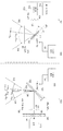
도 1은 환경 스캐닝을 위한 LIDAR 센서(100)를 도시한다. LIDAR 센서(100)는 광을 LIDAR 센서(100)의 환경으로 방출하기 위한 방출 경로(emission path)(101), 및 LIDAR 센서(100)의 환경으로부터 수신된 광을 수신하고 임의적으로 평가하기 위한 수신 경로(reception path)(102)를 포함한다. 1 shows a LIDAR
방출 경로(101)에서, LIDAR 센서(100)는, 광 빔(131)을 LIDAR 센서(100)의 환경으로 편향시키기 위하여 제1 회전 축(111) 주위에서 발진하도록 구성되는 제1 반사 표면(110)을 포함한다. 이것은 제1 반사 표면(110)이 제1 종료 위치로부터 제2 종료 위치까지 제1 회전 방향을 따라 제1 회전 축 주위에서 회전하고, 그 반대도 마찬가지인 것을 의미한다. 제1 회전 축(111)에 관한 제1 반사 표면(110)의 회전 위치에 따라, 광 빔(131)은 상이한 공간적 방향을 따라 LIDAR 센서(100)의 환경으로 편향된다.In the
광 빔(131)은 적어도 하나의 광원(130)에 의해 생성된다. 도 1에서 도시된 예에서, 광 빔(131)은 레이저 광 빔이다. 예를 들어, 광 빔(131)은 펄스화된 레이저 광 빔(pulsed laser light beam)일 수 있다. 펄스화된 레이저 광 빔은 예를 들어, 10 내지 200 kHz 사이의 펄스 반복 주파수를 가질 수 있다. 광원(130)은 일시적으로 제어된 방식으로 광 빔(131)을 생성하기 위하여 구동기(132)에 의해 제어되는 레이저 광 다이오드(133)를 포함한다. 광원(130)은 또한, 빔의 광학적 성질들(예를 들어, 빔 폭)을 조절하고 및/또는 광 빔(131)을 제1 반사 표면(110) 상으로 안내하거나 포커싱하기 위하여, 하나 이상의 렌즈들을 포함하는 렌즈 배열(134)을 포함한다. 도 1에서 표현된 광원(130)은 이 경우에 예로서 선택된다. 예시적인 실시예들에 따르면, 광원(130)은 도 1에서 표현된 것과는 다른 더 많거나(예를 들어, 빔 분리기(beam splitter) 또는 적은 요소들(예를 들어, 무렌즈 배열(no lens arrangement)(134))을 포함할 수 있다. 마찬가지로, 광 빔(131)은 레이저 광 빔을 필요로 하지 않지만, 또한, 임의의 다른 적당한 광 빔일 수 있다. 오직 하나의 광원이 예시적인 실시예들에서 각각 도시되지만, 복수의 광원들(130)은 시야의 상이한 영역들을 조명하기 위하여 예시적인 실시예들에서 각각 제공될 수 있다. 예를 들어, 예시적인 실시예들에서는, 제1 수직 영역에서 시야를 조명하기 위한 제1 광원, 제2 수직 영역에서 시야를 조명하기 위한 제2 광원(130), 및 제3 수직 영역에서 시야를 조명하기 위한 제3 광원(130)이 제공될 수 있고, 제1, 제2, 및 제3 수직 영역들은 각각 상이할 수 있다.The
LIDAR 센서(100)는 또한, 수신 경로(102)에서, LIDAR 센서의 환경으로부터 수신된 광(103)을 LIDAR 센서의 광검출기(140) 상으로 안내하기 위하여 제2 회전 축(121)에 대하여 발진하도록 구성되는 제2 반사 표면(120)을 포함한다.The
제1 반사 표면(110) 및 제2 반사 표면(120)은 본질적으로 동일한 외부 윤곽 또는 형상, 또는 상이한 외부 윤곽들 또는 형상들(그러나 상이한 차원들)을 가질 수 있다. 예를 들어, 2개의 반사 표면들(110 및 120)은 원형 외부 윤곽, 난형(oval) 외부 윤곽, 또는 각진 외부 윤곽을 가질 수 있다. 제1 반사 표면(110)의 면적은 일부 예시적인 실시예들에서, 예를 들어, 광 빔(131)의 단면적(즉, 반사 표면의 평면에서의 광 빔(131)의 면적)만큼 대략 크거나 그보다 약간 더 클 수 있다.The first
제1 반사 표면(110)의 면적은 도 1에 따른 예시적인 실시예에서, 제2 반사 표면(120)의 면적보다 더 작다. 더 큰 제2 반사 표면(120)은 제1 반사 표면(110)과 비교하여, LIDAR 센서의 환경으로부터의 더 많은 광을 광검출기(140) 상으로 안내하는 것을 가능하게 할 수 있다. 예를 들어, 동일한 외부 윤곽으로, 제2 회전 축(121)으로부터의 제2 반사 표면(120)의 외부 윤곽의 최대 수직 거리는 제1 회전 축(111)으로부터의 제1 반사 표면(110)의 외부 윤곽의 최대 수직 거리보다 1.5로부터 10까지의 배수만큼 더 클 수 있다. 예를 들어, 제2 회전 축(121)으로부터의 제2 반사 표면(120)의 외부 윤곽의 최대 수직 거리는 제1 회전 축(111)으로부터의 제1 반사 표면(110)의 외부 윤곽의 최대 수직 거리보다 3배, 4배, 또는 5배 더 클 수 있다. 더 큰 크기 때문에, 제2 반사 표면(120)은 동일한 두께에 대하여, 제1 반사 표면(110)보다 더 큰 관성 모멘트(moment of inertia)를 가진다. 더 큰 관성 모멘트를 감소시키기 위한 두께에서의 감소는 전형적으로, 반사 표면의 스티프니스(stiffness)에 대한 요건 때문에 실제적인 애플리케이션들에서 가능하지 않다.The area of the first
임의적으로, 렌즈 배열(150)은 LIDAR 센서(100)의 환경으로부터 수신된 광을 광검출기(140) 상으로 이미징하기 위하여, 제2 반사 표면(120)과 광검출기(140) 사이에서 수신된 광의 빔 루트(beam route)를 따라 배열될 수 있다.Optionally, the
광검출기(140)는 입사 광의 함수로서 출력 신호(141)를 제공하는 감광성 요소(light-sensitive element)이다. 예를 들어, 광검출기(140)는 단일 감광성 센서 요소(light-sensitive sensor element)(즉, 단일-포인트 센서) 또는 감광성 센서 요소들의 1차원 또는 2차원 배열일 수 있다. 1차원 배열의 경우에, 감광성 센서 요소들은 하나의 공간적 방향을 따라서만 배열되는 반면, 2차원 배열의 경우에, 감광성 센서 요소들은 2개의 상이한(예를 들어, 직교적인) 공간적 방향들을 따라 배열된다. 감광성 센서 요소는 예를 들어, 광다이오드(photodiode), 아발란치 광다이오드(avalanche photodiode)(APD), 단일-광자 아발란치 다이오드(single-photon avalanche diode)(SPAD), 또는 실리콘 광전자 증배기(silicon photoelectron multiplier)들(실리콘 광증배기(silicon photomultiplier)들, SiPM)로서의 SPAD들의 어레이일 수 있다. 도달 시간(time of arrival), 펄스 형상, 및/또는 입사 광의 세기에 관련되는 정보 외에도, 출력 신호(141)는 또한, 광검출기(140) 상에서의 광의 도달 위치에 관련되는 정보를 포함할 수 있다. 출력 신호(141)는 판독 회로(145)에 의하여 판독될 수 있고, 평가 회로(도시되지 않음)에 제공될 수 있다. 예를 들어, 평가 회로는 알려진 평가 방법들을 이용함으로써 출력 신호(141)로부터 광 빔(131)의 펄스의 비행 시간(time of flight)을 결정할 수 있고, 이에 따라, 광 빔(131)이 LIDAR 센서(100)로 다시 반사되었던 객체의 거리를 결정할 수 있다. 유사한 방법으로, 평가 회로는 또한, 추가의 파라미터들, 예를 들어, 반사하는 객체의 표면 성질들(예를 들어, 반사율) 또는 경사를 결정할 수 있다.The
제1 회전 축(111) 및 제2 회전 축(121)은 서로에 대해 평행하게 연장된다. 평행하게 연장되는 회전 축들은 예를 들어, 제1 회전 축(111) 및 제2 회전 축(121)이 단일 라인 상에서(동축으로) 놓이도록, 즉, 제1 회전 축(111) 및 제2 회전 축(121)이 공통 공간적 방향을 따라 오프셋 없이 배향될 수 있도록 하는 그러한 방법으로 배향될 수 있다. 마찬가지로, 제1 회전 축(111) 및 제2 회전 축(121)은 평행하게 배향될 수 있지만, 서로에 대하여 오프셋되게 놓일 수 있고, 즉, 제1 회전 축(111) 및 제2 회전 축(121)은 평행한 공간적 방향들을 따라 서로에 대하여 오프셋되게 배향될 수 있다. 일부 예시적인 실시예들에서, 양자의 제1 반사 표면(110) 및 제2 반사 표면(120)은 하나의 축 주위에서만 각각 회전가능한 미세기계적 미러(micromechanical mirror)들로서 구성되고, 즉, 이들은 하나의 회전 자유도(degree of freedom)만을 가진다. 이러한 미러들은 또한, 1차원 미러들(1D 미러들)로서 지칭된다. 이 예시적인 실시예들에서, 제1 회전 축(111) 및 제2 회전 축(121)은 그러므로, 방출 경로(101) 또는 수신 경로(102)의 추가의 컴포넌트들에 대하여 각각 강성(rigid)이다.The
LIDAR 센서(100)는 추가로, 제1 최대 편위 각도 ![]()
![]()
![]()
![]()
![]()
![]()
![]()
![]()
![]()
![]()
제1 최대 편위 각도 ![]()
![]()
![]()
![]()
![]()
![]()
![]()
![]()
![]()
![]()
![]()
![]()
![]()
![]()
![]()
![]()
제2 반사 표면(120)은 편향된 광 빔(131)에 의해 방금 스캐닝되거나 조사되지 않은 LIDAR 센서(100)의 환경의 영역들로부터의 광을 억압하기 위하여, 광을 선택적으로 광검출기(140) 상으로 안내하는 것을 가능하게 한다. 이에 대응하여, 광검출기(140)를 타격하는 배경 광의 비율은 감소될 수 있다. 다시 말해서: 제2 반사 표면(120)은 입사 배경 광과 비교하여, 광검출기(140)를 타격하는 편향된 광 빔(131)의 반사된 광의 비율을 증가시키는 것을 가능하게 할 수 있다. 제2 반사 표면(120)의 더 큰 면적은 추가로, 더 큰 광의 양을 광검출기(140) 상으로 안내하는 것을 가능하게 한다. 제2 반사 표면(120)의 더 작은 각도 진폭(예를 들어, 제1 반사 표면(110)과 비교하여 5배)은 작은 각도 범위에서 방향-감지 수신(direction-sensitive reception)을 허용한다. 양자의 방출 경로(101) 및 수신 경로(102)에서의 발진하는 반사 표면들의 이용은 그러므로, 광검출기(140)에서 신호-대-잡음-비율(signal-to-noise-ratio)(SNR)에서의 (상당한) 증가를 허용할 수 있다. 개선된 SNR 때문에, LIDAR 센서(100)는 또한, 100미터 이상의 범위에서의 LIDAR 측정들을 허용할 수 있다. LIDAR 센서(100)는 예를 들어, 150미터 이상의 범위들을 갖는 장거리 LIDAR를 허용할 수 있다.The second
LIDAR 센서(100)는 예를 들어, 심지어 주간 또는 햇빛에서 150미터 이상의 거리에서 차량의 환경을 검출하기 위하여 차량(도시되지 않음)에서 이용될 수 있다.The
광 빔(131)이 편향될 수 있는 LIDAR 센서(100)의 제1 시야 영역은 제1 최대 편위 각도 ![]()
![]()
![]()
![]()
![]()
![]()
![]()
![]()
![]()
![]()
![]()
![]()
![]()
![]()
발진 동안에 미러(120)를 타격하는 광이 제2 시야 영역으로부터 광검출기(140) 상으로 안내될 수 있는 제2 시야 영역은 제2 최대 편위 각도 ![]()
![]()
![]()
![]()
제2 시야 영역을, 제1 시야 영역에 대응하는 수신 시야 영역으로 확대하기 위하여, LIDAR 센서(100)는 수신 광학계(optical reception system)(180)를 포함할 수 있다. 예를 들어, 수신 광학계(180)는 (예를 들어, 초점 길이의 측면에서) 렌즈계(170)와 상이한 것일지라도, 유사한 렌즈계일 수 있다. 도 1에서, 수신 시야 영역은 LIDAR 센서(100)의 환경으로부터 입사하는 광을 위한 최대 가능한 빔 루트들(105' 및 106')에 의해 각각 표시된다. 제2 반사 표면(120)의 발진과 조합한 수신 광학계(180)에 의하여, ![]()
![]()
![]()
![]()
![]()
![]()
![]()
![]()
수신 광학계(180)는 수신 광학계(180)에 의해 수신되는 광을 위한 증가된 다이버전스 ![]()
![]()
![]()
![]()
![]()
![]()
![]()
![]()
LIDAR 센서(100)는 그러므로, 큰 애퍼처를 갖는 간단하고 경제적인 광학적 설계를 허용할 수 있다. 주간에서의 동작 동안에, 광검출기(140)의 SNR은 이에 따라, (상당히) 개선될 수 있다.The
제1 반사 표면(110)은 예를 들어, 2.5 mm의 직경을 가질 수 있고, 제2 반사 표면(120)은 5 mm 이상(예를 들어, 8 mm)의 직경을 가질 수 있다. 0.1°의 스캐닝 해상도로, 제2 시야 영역은 그 다음으로, 예를 들어, 2°의 애퍼처 각도를 가질 수 있다. 이러한 방법으로, 높은 SNR은 예를 들어, 광검출기(140)의 감광성 센서 요소들의 1차원 배열을 위하여 달성될 수 있어서, 예를 들어, 차량들을 위한 장거리 LIDAR 애플리케이션들을 위하여 요구되는 바와 같이, 150 내지 250 미터 사이의 LIDAR 측정들이 가능하게 될 수 있다.The first
제어 회로(160)는 제1 반사 표면(110) 및 제2 반사 표면(120)이 제1 회전 축(111) 및 제2 회전 축(121) 주위에서 동기적으로 각각 발진하도록 하는 그러한 방법으로 제1 반사 표면(110) 및 제2 반사 표면(120)을 구동하도록 적응된다. 예를 들어, 제어 회로(160)는 제1 반사 표면(110) 및 제2 반사 표면(120)이 제1 회전 축(111) 및 제2 회전 축(121) 주위에서 서로에 대한 동일한 주파수 및 미리 결정된 위상 관계로 각각 발진하도록 하는 그러한 방법으로 제1 반사 표면(110) 및 제2 반사 표면(120)을 구동하도록 적응될 수 있다. 다시 말해서: 제1 반사 표면(110)의 발진 주파수 ![]()
![]()
![]()
![]()
제1 반사 표면(110) 및 제2 반사 표면(120)은 예를 들어, MEMS 미러들일 수 있다.The first
제1 반사 표면(110) 및 제2 반사 표면(120)은 기계적으로 결합될 수 있거나, 또는 기계적으로 결합해제될 수 있다. 예를 들어, 제1 반사 표면(110) 및 제2 반사 표면(120)은 (공통) 반도체 칩 상에서 형성될 수 있고, 기계적으로 결합될 수 있다. 이것은 도 2에서의 반도체 칩(200)을 위한 예로서 도시된다. 2개의 반사 표면들(110 및 120)은 프레임(240) 상의 스트러트 구조체(strut structure)(250)에 의하여 유지된다. 제어 회로(160)에 의해 대응하게 구동되는 액츄에이터들(250-1, 250-2, 250-3)에 의하여, 반사 표면들(110 및 120)은 예를 들어, 정전기적 또는 자기적 효과들에 의하여 발진들에서 여기된다. 여기(excitation)는 공진 방식으로(resonantly), 또는 대안적으로, 준-정적으로(quasi-statically) 수행될 수 있다. 준-정적 여기는 비공진 방식으로(nonresonantly) 동작할 수 있는 시스템을 의미하도록 의도되지만(즉, 그것은 미리 결정된 각도를 정적으로 유지할 수 있음), 정적으로 동작되는 것이 아니라, 발진 제어된 방식으로 동작된다. 도 2에서 도시된 반도체 칩(200)에서, 반사 표면들(110 및 120)은 예컨대, MEMS 미러들로서 표현된다.The first
반사 표면들(110 및 120)이 기계적으로 결합되지 않고, 예를 들어, 2개의 상이한 반도체 칩들 상에서 형성될 경우에, 제어 회로(160)는 도 1에서 표시된 바와 같이, 반사 표면들(110 및 120)을 별도로 각각 구동하기 위하여, 예를 들어, 2개의 서브회로들(161 및 162)을 포함할 수 있다.In the case where the
도 1에서 도시된 LIDAR 센서(100)는 일부 예시적인 실시예들에서, 또한, 양자의 방출 경로(101) 및 수신 경로(102)에서 하나 이상의 추가의 반사 표면들을 포함할 수 있다.The
예를 들어, LIDAR 센서(100)는 또한, 추가의 광 빔을 LIDAR 센서(100)의 환경으로 편향시키기 위하여 제3 회전 축 주위에서 제1 반사 표면과 동기적으로 발진하도록 구성되는 제3 반사 표면(표현되지 않음)을 포함할 수 있다. 제3 회전 축은 제1 회전 축(111)에 대하여 평행하다(예를 들어, 이와 동축임). 제3 반사 표면은 일부 예시적인 실시예들에서, 제1 반사 표면(110)과 동일하게 구성될 수 있다. 이에 대응하여, 제어 회로(160)는 제1 최대 편위 각도로 제3 회전 축 주위에서 발진하도록 제3 반사 표면을 구동하도록 구성될 수 있다. 대안으로서, 제3 반사 표면은 또한, 제1 반사 표면(110)과는 상이한 차원들을 가질 수 있고, 이에 대응하여, 제1 최대 편위 각도와는 상이한 편위 각도로 제3 회전 축 주위에서 발진하도록 제어 회로(160)에 의해 구동될 수 있다. 제어 회로(160)는 예를 들어, 동위상 또는 제1 반사 표면(110)에 대한 미리 결정된 위상 시프트로 발진하도록 제3 반사 표면을 구동할 수 있다.For example, the
대안으로서, 또는 추가적으로, LIDAR 센서(100)는 또한, LIDAR 센서(100)의 환경으로부터 수신된 광을 광검출기(140) 상으로 안내하기 위하여 제4 회전 축 주위에서 제2 반사 표면(120)과 동기적으로 발진하도록 구성되는 제4 반사 표면을 포함할 수 있다. 제4 회전 축은 제2 회전 축(121)에 대하여 평행하다(예를 들어, 이와 동축임). 제4 반사 표면은 일부 예시적인 실시예들에서, 제2 반사 표면(120)과 동일하게 구성될 수 있다. 이에 대응하여, 제어 회로(160)는 제2 최대 편위 각도로 제4 회전 축 주위에서 발진하도록 제4 반사 표면을 구동하도록 구성될 수 있다. 대안으로서, 제4 반사 표면은 또한, 제2 반사 표면(120)과는 상이한 차원들을 가질 수 있고, 이에 대응하여, 제2 최대 편위 각도와는 상이한 편위 각도로 제4 회전 축 주위에서 발진하도록 제어 회로(160)에 의해 구동될 수 있다. 제어 회로(160)는 예를 들어, 동위상 또는 제2 반사 표면(120)에 대한 미리 결정된 위상 시프트로 발진하도록 제4 반사 표면을 구동할 수 있다.As an alternative, or additionally, the
LIDAR 센서(100)는 양자의 방출 및 수신 경로에서 발진 표면들을 이용한다. 이러한 방법으로, 스캔 속력은 기존의 LIDAR 시스템들과 비교하여 증가될 수 있고, 즉, 프레임 레이트(frame rate)는 개선될 수 있고, 더 빠른 객체들이 레코딩될 수 있다. 각각의 위치에 대한 레코딩된 LIDAR 데이터의 더 큰 평균화가 또한 가능하게 될 수 있어서, SNR은 추가로 증가될 수 있다.The
도 3은 LIDAR 센서(300)의 추가의 예시적인 실시예를 도시한다. LIDAR 센서(300)는 광을 LIDAR 센서(300)의 환경으로 방출하기 위한 방출 경로(301), 및 LIDAR 센서(300)의 환경으로부터 수신된 광을 수신하고 평가하기 위한 수신 경로(302)를 다시 포함한다. 3 shows a further exemplary embodiment of the
방출 경로(301)는 제1 광 빔(331)을 LIDAR 센서(300)의 환경으로 편향시키기 위하여 제1 회전 축(311) 주위에서 발진하도록 구성되는 제1 반사 표면(310)을 포함한다. 방출 경로(301)는 또한, 제2 광 빔(332)을 LIDAR 센서(300)의 환경으로 편향시키기 위하여 제2 회전 축(321) 주위에서 발진하도록 구성되는 제2 반사 표면(320)을 포함한다. 2개의 반사 표면들(310 및 320)은 LIDAR 센서(300) 내부의 광 빔들(331 및 332)을 각각, 광 빔들(331 및 332)을 LIDAR 센서(300)의 환경으로 투과시키는 요소 상으로 편향시킨다. 예를 들어, 2개의 반사 표면들(310 및 320)은 광 빔들(331 및 332)을, 광 빔들(331 및 332)이 LIDAR 센서(300)의 환경으로 이를 통해 투과하였던 (예를 들어, 하나 이상의 렌즈들을 포함하는) 방출 광학기기(370) 상으로 편향시킬 수 있다. 반사 표면들(310 및 320)은 그러므로 각각, 광 빔(331 또는 332)을 단일 반사에 의하여 LIDAR 센서(300)의 환경으로 편향시키는 것을 가능하게 한다.The
제1 반사 표면(310) 및 제2 반사 표면(320)은 예를 들어, MEMS 미러들일 수 있다.The first
제1 회전 축(311) 및 제2 회전 축(321)은 서로에 대해 평행하게 연장된다. 예를 들어, 제1 회전 축(311) 및 제2 회전 축(321)은 단일 라인 상에서 놓일 수 있고, 즉, 제1 회전 축(311) 및 제2 회전 축(321)은 공통 공간적 방향을 따라 오프셋 없이 배향될 수 있다. 대안으로서, 제1 회전 축(311) 및 제2 회전 축(321)은 서로에 대하여 오프셋되게 놓일 수 있고, 즉, 제1 회전 축(311) 및 제2 회전 축(321)은 평행한 공간적 방향들을 따라 서로에 대하여 오프셋되게 배향될 수 있다.The first rotation axis 311 and the second rotation axis 321 extend parallel to each other. For example, the first axis of rotation 311 and the second axis of rotation 321 may lie on a single line, that is, the first axis of rotation 311 and the second axis of rotation 321 may follow a common spatial direction. It can be oriented without offset. Alternatively, the first axis of rotation 311 and the second axis of rotation 321 may be placed offset relative to each other, that is, the first axis of rotation 311 and the second axis of rotation 321 are parallel in the spatial direction It can be oriented offset relative to each other along them.
광 빔들(331 및 332)은 광원(330)으로부터 제1 반사 표면(310) 및 제2 반사 표면(320) 상으로 각각 방사되거나 지향된다. 도 1에서 도시된 예에서, 광 빔들(331 및 332)은 레이저 광 빔들이다. 광원(330)은 위에서 설명된 광원(130)과 실질적으로 유사하게 구성된다. 광원(330)은 구동기(332) 및 광학기기(334)에 의해 제어된 적어도 하나의 레이저 광 다이오드(333)를 포함한다. 일부 예시적인 실시예들에서, 광원은 다수의 제어된 레이저 광 다이오드들을 포함한다. 복수의 레이저 광 다이오드들은 회전 축들(311 및 321)에 대해 평행한 방향을 따라 배열될 수 있다. 그러므로, 그 광 스폿 영역(light spot region)이 회전 축들(311 및 321)에 대해 평행한 방향으로 종방향으로(longitudinally) 확대되는 광 빔을 생성하는 것이 가능하다. 일부 예시적인 실시예들에서, 하나 이상의 레이저 광 다이오드들(333)은 양자의 광 빔들(331 및 332)을 생성할 수 있고, 광학기기(334)는 광 빔들을 제1 반사 표면(310) 또는 제2 반사 표면(320) 상으로 각각 순차적으로 안내할 수 있다. 대안적인 예시적인 실시예들에서, 레이저 광 다이오드(333)는 광학기기(334)의 빔 분리기(예를 들어, 프리즘(prism))에 의해 광 빔들(331 및 332)로 분리되는 단일 광 빔을 생성한다. 도 3에서 표현된 광원(330)은 이 경우에 예로서 선택된다. 예시적인 실시예들에 따르면, 광원(330)은 도 3에서 표현된 것과는 다른 더 많거나 더 적은 요소들을 포함할 수 있다. 마찬가지로, 광 빔(331)은 레이저 광 빔을 필요로 하지 않지만, 또한, 임의의 다른 적당한 광 빔일 수 있다.The light beams 331 and 332 are emitted or directed from the
수신 경로(302)는 LIDAR 센서(300)의 환경으로부터 수신된 광을 수신하도록 구성되는 광검출기(340)를 포함한다. 광검출기(340)는 위에서 설명된 광검출기(140)와 실질적으로 동일하다. 광검출기(340)의 출력 신호(341)는 판독 회로(345)에 의하여 판독될 수 있고, 위에서 설명된 원리들에 따라 평가 회로(도시되지 않음)에 의해 평가될 수 있다.The receive
LIDAR 센서(300)는 또한, 제1 반사 표면(310) 및 제2 반사 표면(320)이 제1 회전 축(311) 및 제2 회전 축(321) 주위에서 동기적으로 각각 발진하도록 하는 그러한 방법으로 제1 반사 표면(310) 및 제2 반사 표면(320)을 구동하도록 적응되는 제어 회로(360)를 포함한다. 예를 들어, 제어 회로(360)는 제1 회전 축(311) 및 제2 회전 축(321) 주위에서 서로에 대한 동일한 주파수 및 미리 결정된 위상 관계로 각각 발진하도록 제1 반사 표면(310) 및 제2 반사 표면(320)을 구동하도록 적응될 수 있다. 제1 반사 표면(310)의 발진 주파수 ![]()
![]()
![]()
![]()
제1 반사 표면(310) 및 제2 반사 표면(320)은 제1 광 빔(331) 및 제2 광 빔(332)을 LIDAR 센서(300)의 상이한 시야 영역들로 편향시키도록 구성된다.The first
제1 광 빔(331)이 편향될 수 있는, LIDAR 센서(300)의 제1 시야 영역은 제1 반사 표면(310)의 발진 이동에 의해 결정된다. 도 3에서, 제1 시야 영역은 제1 광 빔(331)을 위한 (제1 반사 표면(310)의 발진 때문에) 최대 가능한 빔 루트들(303 및 304)에 의해 각각 표시된다. 제2 광 빔(332)이 편향될 수 있는, LIDAR 센서(300)의 제2 시야 영역은 제2 반사 표면(320)의 발진 이동에 의해 결정된다. 도 3에서, 제2 시야 영역은 제2 광 빔(332)을 위한 (제2 반사 표면(320)의 발진 때문에) 최대 가능한 빔 루트들(304 및 305)에 의해 각각 표시된다.The first viewing area of the
제1 광 빔(331) 및 제2 광 빔(332)이 편향될 수 있는 상이한 시야 영역들은 예를 들어, 반사 표면들(310 및 320)이 발진할 수 있는 상이한 회전 각도 범위들에 의해 조절될 수 있다. 예를 들어, 제2 반사 표면(320)의 휴식 위치 또는 중심 위치는 (예를 들어, 회전된) 제1 반사 표면(310)의 휴식 위치 또는 중심 위치와 상이할 수 있어서, 이와 다르게 동일한 발진 이동으로, 반사 표면들(310 및 320)은 광 빔들(331 및 332)을 LIDAR 센서(300)의 상이한 시야 영역들로 편향시킨다.The different viewing areas in which the first light beam 331 and the second
동기적으로 발진하는, 방출 경로(301)에서의 복수의 반사 표면들의 이용은 LIDAR 센서(300)에 의해 스캐닝될 수 있는 영역을 확대하는 것을 가능하게 할 수 있다. 예를 들어, LIDAR 센서(300)는 오직 단일 발진 MEMS 미러를 가지는 기존의 센서들과 비교하여 더 큰 횡방향 영역(lateral region)을 스캐닝할 수 있다.The use of a plurality of reflective surfaces in the
단일 발진 MEMS 미러만을 가지는 기존의 센서들과 비교하여, 복수의 반사 표면들의 이용 때문에, 전체 시야 영역은 그러므로, 반사 표면들 중의 하나에 의하여 각각 스캐닝되는 복수의 서브영역들로 분할될 수 있다. 동일한 프레임 또는 스캔 레이트로, LIDAR 센서(300)의 해상도는 그러므로, 기존의 센서들과 비교하여 증가될 수 있다. 대안으로서, 동일한 해상도로, LIDAR 센서(300)의 프레임 또는 스캔 레이트는 또한, 기존의 센서들과 비교하여 증가될 수 있다.Compared to conventional sensors having only a single oscillation MEMS mirror, because of the use of multiple reflective surfaces, the entire viewing area can therefore be divided into a plurality of sub-regions, each scanned by one of the reflective surfaces. At the same frame or scan rate, the resolution of the
제1 반사 표면(310) 및 제2 반사 표면(320)은 다시, 기계적으로 결합될 수 있거나, 또는 기계적으로 결합해제될 수 있다. 예를 들어, 제1 반사 표면(310) 및 제2 반사 표면(320)은 (공통) 반도체 칩 상에서 형성될 수 있고, 기계적으로 결합될 수 있거나, 2개의 별도의 반도체 칩들 상에서 형성될 수 있고, 기계적으로 결합해제될 수 있다.The first
도 3에서 도시된 LIDAR 센서(300)는 2개의 광 빔들(331 및 332)을 센서의 환경으로 각각 편향시키기 위하여 2개의 반사 표면들(310 및 320)을 포함한다. 예시적인 실시예들에 따르면, LIDAR 센서(300)는 임의적으로 또한, 추가의 광 빔들을 센서의 환경으로 편향시키기 위하여 추가의 반사 표면들(도시되지 않음)을 포함할 수 있다. 예를 들어, LIDAR 센서(300)는 광 빔들을 센서의 환경으로 편향시키기 위하여 3개, 4개, 5개 이상의 반사 표면들을 포함할 수 있다. LIDAR 센서(300)는 그러므로, 전체 스캐닝된 시야 영역을 n 개의 서브영역들로 분할하는 것을 가능하게 할 수 있고, 여기서, n은 스캐닝을 위하여 이용되는, 방출 경로(301)에서의 반사 표면들의 수를 표시한다.The
임의적으로, LIDAR 센서(300)는 또한, LIDAR 센서(300)의 환경으로부터 수신된 광을 광검출기(340) 상으로 안내하기 위하여, 수신 경로(302)에서 하나 이상의 반사 표면들을 포함할 수 있다. 예를 들어, LIDAR 센서(300)는 LIDAR 센서(300)의 환경으로부터 수신된 광을 광검출기(340) 상으로 안내하기 위하여 제3 회전 축 주위에서 제1 반사 표면(310)과 동기적으로 발진하도록 구성되는 제3 반사 표면(도시되지 않음)을 포함할 수 있다. 제3 회전 축은 제1 회전 축(311)에 대하여 평행하다(예를 들어, 이와 동축임). 제3 반사 표면은 제1 반사 표면과 동일하게 구성될 수 있거나, 도 1과 관련하여 위에서 예시된 바와 같이, 그것은 제1 반사 표면보다 더 클 수 있다. 제어 회로(360)에 의한 제3 반사 표면의 구동은 예를 들어, 도 1과 관련하여 위에서 설명된 원리들에 따라 수행될 수 있다. 예를 들어, 제어 회로(360)는 반사 표면들(310 및 320) 중의 하나와 동기적으로 발진하도록 제3 반사 표면을 구동하도록 구성될 수 있다.Optionally, the
추가로, LIDAR 센서(300)는 임의적으로 또한, 환경으로부터 입사하는 광을 광검출기(380) 또는 제3 반사 표면 상으로 이미징하기 위하여 수신 광학기기(380)(예를 들어, 렌즈계)를 포함할 수 있다.Additionally, the
도 4는 추가의 LIDAR 센서(400)를 표현한다. LIDAR 센서(400)는 LIDAR 센서(300)와 실질적으로 동일하지만, 제1 반사 표면(310) 및 제2 반사 표면(320)은 제1 광 빔(331) 및 제2 광 빔(332)을 LIDAR 센서의 동일한 시야 영역으로 편향시키도록 구성된다. 4 represents an
예를 들어, 이것은 반사 표면들(310 및 320)이 발진할 수 있는 동일한 회전 각도 범위들에 의해 달성될 수 있다. 제2 반사 표면(320)의 휴식 위치 또는 중심 위치는 예를 들어, 제1 반사 표면(310)의 휴식 위치 또는 중심 위치와 동일할 수 있어서, 이와 다르게 동일한 발진 이동으로, 반사 표면들(310 및 320)은 광 빔들(331 및 332)을 LIDAR 센서(400)의 동일한 시야 영역으로 편향시킨다.For example, this can be achieved by the same range of rotation angles that
LIDAR 센서(400)의 동일한 시야 영역으로의 복수의 광 빔들의 편향에 의해, 측정 포인트들의 수는 단일 발진 MEMS 미러만을 가지는 기존의 센서들과 비교하여 증가될 수 있다. 이에 대응하여, LIDAR 센서(400)의 스캔 해상도가 개선될 수 있다. 복수의 반사 표면들에 의한 동일한 시야 영역의 스캐닝 때문에, LIDAR 센서(400)의 프레임 또는 스캔 레이트는 또한, 기존의 센서들과 비교하여 증가될 수 있다.By deflection of a plurality of light beams into the same viewing area of the
LIDAR 센서들의 동작에 관련되는 위에서 설명된 양태들을 한번 더 요약하기 위하여, 도 5 및 도 6은 또한, LIDAR 센서들을 위한 방법들의 2개의 플로우차트들을 도시한다.To further summarize the above-described aspects related to the operation of LIDAR sensors, FIGS. 5 and 6 also show two flowcharts of methods for LIDAR sensors.
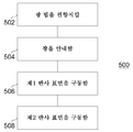
도 5는 LIDAR 센서를 위한 제1 방법(500)의 플로우차트를 도시한다. 방법(500)은 제1 회전 축 주위에서 발진하는 제1 반사 표면에 의하여, 광 빔을 LIDAR 센서의 환경으로 편향시키는 단계(502)를 포함한다. 방법(500)은 또한, 제2 회전 축 주위에서 발진하는 제2 반사 표면에 의하여, LIDAR 센서의 환경으로부터 수신된 광을 LIDAR 센서의 광검출기 상으로 안내하는 단계(504)를 포함한다. 제1 회전 축 및 제2 회전 축은 서로에 대해 평행하게 연장되고, 제1 반사 표면의 면적은 제2 반사 표면의 면적보다 더 작다. 방법(500)은 또한, 제1 회전 축 주위에서 제1 최대 편위 각도로 발진하도록 제1 반사 표면을 구동하는 단계(506)를 포함한다. 방법(500)은 추가로, 제2 회전 축 주위에서 제2 최대 편위 각도로 발진하도록 제2 반사 표면을 구동하는 단계(508)를 포함한다. 제1 최대 편위 각도는 제2 최대 편위 각도보다 더 크다. 5 shows a flowchart of a
방법(500)의 추가의 세부사항들 및 양태들은 추가의 예시적인 실시예들(예를 들어, 도 1 및 도 2)과 관련하여 위에서 설명된다. 방법(500)은 추가의 예시적인 실시예들에 따른 하나 이상의 임의적인 특징들을 포함할 수 있다.Additional details and aspects of
LIDAR 센서를 위한 제2 방법(600)의 플로우차트가 도 6에서 도시된다. 방법(600)은 제1 회전 축 주위에서 발진하는 제1 반사 표면에 의하여, 제1 광 빔을 LIDAR 센서의 환경으로 편향시키는 단계(602)를 포함한다. 방법(600)은 추가로, 제2 회전 축 주위에서 발진하는 제2 반사 표면에 의하여, 제2 광 빔을 LIDAR 센서의 환경으로 편향시키는 단계(604)를 포함한다.A flowchart of a
방법(600)의 추가의 세부사항들 및 양태들은 추가의 예시적인 실시예들(예를 들어, 도 3 및 도 4)과 관련하여 위에서 설명된다. 방법(600)은 추가의 예시적인 실시예들에 따른 하나 이상의 임의적인 특징들을 포함할 수 있다.Additional details and aspects of
본원에서 설명된 예시적인 실시예들은 다음과 같이 요약될 수 있다:The exemplary embodiments described herein can be summarized as follows:
일부 예시적인 실시예들은 LIDAR 센서에 관한 것이다. LIDAR 센서는, 광 빔을 LIDAR 센서의 환경으로 편향시키기 위하여 제1 회전 축 주위에서 발진하도록 구성되는 제1 반사 표면을 포함한다. LIDAR 센서는 또한, LIDAR 센서의 환경으로부터 수신된 광을 LIDAR 센서의 광검출기 상으로 안내하기 위하여 제2 회전 축 주위에서 발진하도록 구성되는 제2 반사 표면을 포함한다. 제1 회전 축 및 제2 회전 축은 서로에 대해 평행하게 연장된다. LIDAR 센서는 또한, 제1 회전 축 주위에서 제1 최대 편위 각도로 발진하도록 제1 반사 표면을 구동하고, 제2 회전 축 주위에서 제2 최대 편위 각도로 발진하도록 제2 반사 표면을 구동하도록 적응되는 제어 회로를 포함한다. 제1 최대 편위 각도는 제2 최대 편위 각도보다 더 크고, 제1 반사 표면의 면적은 제2 반사 표면의 면적보다 더 작다.Some exemplary embodiments relate to LIDAR sensors. The LIDAR sensor includes a first reflective surface configured to oscillate around the first axis of rotation to deflect the light beam into the environment of the LIDAR sensor. The LIDAR sensor also includes a second reflective surface that is configured to oscillate around the second axis of rotation to direct light received from the LIDAR sensor's environment onto the LIDAR sensor's photodetector. The first axis of rotation and the second axis of rotation extend parallel to each other. The LIDAR sensor is also adapted to drive the first reflective surface to oscillate at a first maximum deflection angle around the first axis of rotation, and to drive the second reflective surface to oscillate at a second maximum deflection angle around the second axis of rotation. Includes control circuit. The first maximum deviation angle is greater than the second maximum deviation angle, and the area of the first reflective surface is smaller than the area of the second reflective surface.
일부 예시적인 실시예들에서, 제어 회로는 제1 회전 축 및 제2 회전 축 주위에서 동기적으로 각각 발진하도록 제1 반사 표면 및 제2 반사 표면을 구동하도록 적응된다.In some example embodiments, the control circuit is adapted to drive the first reflective surface and the second reflective surface to oscillate synchronously around the first and second rotational axes, respectively.
예를 들어, 제어 회로는 제1 회전 축 및 제2 회전 축 주위에서 서로에 대한 동일한 주파수 및 미리 결정된 위상 관계로 각각 발진하도록 제1 반사 표면 및 제2 반사 표면을 구동하도록 적응될 수 있다.For example, the control circuit can be adapted to drive the first reflective surface and the second reflective surface to oscillate respectively with the same frequency and predetermined phase relationship to each other around the first and second rotational axes.
일부 예시적인 실시예들에 따르면, LIDAR 센서는 또한, 제2 입체각으로부터의 광을 제2 반사 표면 상으로 이미징하도록 구성되는 수신 광학계를 포함하고, 제2 입체각은 제1 반사 표면이 광 빔을 편향시키는 제1 입체각과 동일하거나 이보다 더 크다.According to some exemplary embodiments, the LIDAR sensor also includes a receiving optical system configured to image light from the second stereoscopic angle onto the second reflective surface, wherein the second stereoscopic angle is such that the first reflective surface deflects the light beam. Let the same as or greater than the first solid angle.
예를 들어, 수신 광학계는 제1 렌즈계일 수 있고, LIDAR 센서는 추가로, 제1 렌즈계와 상이하고 제1 반사 표면에 의해 편향된 광 빔들을 LIDAR 센서의 환경으로 투과하도록 적응되는 제2 렌즈계를 포함할 수 있다.For example, the receiving optical system can be a first lens system, and the LIDAR sensor further includes a second lens system different from the first lens system and adapted to transmit light beams deflected by the first reflective surface into the environment of the LIDAR sensor. can do.
일부 예시적인 실시예들에서, 제1 최대 편위 각도는 제2 최대 편위 각도보다 적어도 3배 크다.In some exemplary embodiments, the first maximum deviation angle is at least three times greater than the second maximum deviation angle.
일부 예시적인 실시예들에 따르면, 광검출기는 감광성 센서 요소들의 1차원 또는 2차원 배열이다.According to some exemplary embodiments, the photodetector is a one-dimensional or two-dimensional arrangement of photosensitive sensor elements.
일부 예시적인 실시예들에서, 제1 반사 표면 및 제2 반사 표면은 기계적으로 결합된다.In some demonstrative embodiments, the first reflective surface and the second reflective surface are mechanically coupled.
대안으로서, 제1 반사 표면 및 제2 반사 표면은 또한, 기계적으로 결합해제될 수 있다.Alternatively, the first reflective surface and the second reflective surface can also be mechanically disengaged.
일부 예시적인 실시예들에 따르면, 제1 반사 표면은 MEMS 미러이다.According to some example embodiments, the first reflective surface is a MEMS mirror.
일부 예시적인 실시예들에서, LIDAR 센서는 또한, 추가의 광 빔을 LIDAR 센서의 환경으로 편향시키기 위하여 제3 회전 축 주위에서 제1 반사 표면과 동기적으로 발진하도록 구성되는 제3 반사 표면을 포함한다.In some demonstrative embodiments, the LIDAR sensor also includes a third reflective surface configured to oscillate synchronously with the first reflective surface around the third axis of rotation to deflect additional light beams into the environment of the LIDAR sensor. do.
일부 예시적인 실시예들에 따르면, LIDAR 센서는 또한, LIDAR 센서의 환경으로부터 수신된 광을 광검출기 상으로 안내하기 위하여 제4 회전 축 주위에서 제2 반사 표면과 동기적으로 발진하도록 구성되는 제4 반사 표면을 포함한다.According to some exemplary embodiments, the LIDAR sensor is also configured to oscillate synchronously with the second reflective surface around the fourth axis of rotation to direct light received from the LIDAR sensor's environment onto the photodetector. Includes reflective surfaces.
일부 예시적인 실시예들에서, LIDAR 센서는 또한, 광 빔 및 임의적으로, 추가의 광 빔을 생성하도록 적응되는 광원을 포함한다.In some demonstrative embodiments, the LIDAR sensor also includes a light beam and, optionally, a light source that is adapted to generate an additional light beam.
예시적인 실시예들은 또한, 추가의 LIDAR 센서에 관한 것이다. LIDAR 센서는, 제1 광 빔을 LIDAR 센서의 환경으로 편향시키기 위하여 제1 회전 축 주위에서 발진하도록 구성되는 제1 반사 표면을 포함한다. LIDAR 센서는 추가로, 제2 광 빔을 LIDAR 센서의 환경으로 편향시키기 위하여 제2 회전 축 주위에서 발진하도록 구성되는 제2 반사 표면을 포함한다.Exemplary embodiments also relate to additional LIDAR sensors. The LIDAR sensor includes a first reflective surface configured to oscillate around the first axis of rotation to deflect the first light beam into the environment of the LIDAR sensor. The LIDAR sensor further includes a second reflective surface configured to oscillate around the second axis of rotation to deflect the second light beam into the environment of the LIDAR sensor.
일부 예시적인 실시예들에서, LIDAR 센서는 추가로, 제1 회전 축 및 제2 회전 축 주위에서 동기적으로 각각 발진하도록 제1 반사 표면 및 제2 반사 표면을 구동하도록 적응되는 제어 회로를 포함한다.In some demonstrative embodiments, the LIDAR sensor further includes a control circuit adapted to drive the first reflective surface and the second reflective surface to oscillate synchronously around the first and second rotation axes, respectively. .
예를 들어, 제어 회로는 제1 회전 축 및 제2 회전 축 주위에서 서로에 대한 동일한 주파수 및 미리 결정된 위상 관계로 각각 발진하도록 제1 반사 표면 및 제2 반사 표면을 구동하도록 적응될 수 있다.For example, the control circuit can be adapted to drive the first reflective surface and the second reflective surface to oscillate respectively with the same frequency and predetermined phase relationship to each other around the first and second rotational axes.
일부 예시적인 실시예들에 따르면, 제1 반사 표면 및 제2 반사 표면은 제1 광 빔 및 제2 광 빔을 LIDAR 센서의 동일한 시야 영역으로 편향시키도록 구성된다.According to some exemplary embodiments, the first reflective surface and the second reflective surface are configured to deflect the first light beam and the second light beam to the same viewing area of the LIDAR sensor.
일부 예시적인 실시예들에서, 제1 반사 표면 및 제2 반사 표면은 제1 광 빔 및 제2 광 빔을 LIDAR 센서의 상이한 시야 영역들로 편향시키도록 구성된다.In some demonstrative embodiments, the first reflective surface and the second reflective surface are configured to deflect the first light beam and the second light beam to different viewing areas of the LIDAR sensor.
일부 예시적인 실시예들에 따르면, LIDAR 센서는 추가로, LIDAR 센서의 환경으로부터 수신된 광을 수신하도록 구성되는 광검출기를 포함한다.According to some exemplary embodiments, the LIDAR sensor further includes a photodetector configured to receive light received from the environment of the LIDAR sensor.
일부 예시적인 실시예들에서, LIDAR 센서는, LIDAR 센서의 환경으로부터 수신된 광을 광검출기 상으로 안내하기 위하여 제3 회전 축 주위에서 제1 반사 표면과 동기적으로 발진하도록 구성되는 제3 반사 표면을 포함한다.In some demonstrative embodiments, the LIDAR sensor is configured to oscillate synchronously with the first reflective surface around a third rotational axis to guide light received from the LIDAR sensor's environment onto the photodetector. It includes.
일부 예시적인 실시예들에서, LIDAR 센서는 추가로, 제1 광 빔 및 제2 광 빔을 제1 반사 표면 및 제2 반사 표면 상으로 각각 방사하도록 적응되는 광원을 포함한다.In some demonstrative embodiments, the LIDAR sensor further includes a light source adapted to emit the first light beam and the second light beam onto the first reflective surface and the second reflective surface, respectively.
추가의 예시적인 실시예들은 LIDAR 센서를 위한 방법에 관한 것이다. 방법은 제1 회전 축 주위에서 발진하는 제1 반사 표면에 의하여, 광 빔을 LIDAR 센서의 환경으로 편향시키는 단계를 포함한다. 방법은 또한, 제2 회전 축 주위에서 발진하는 제2 반사 표면에 의하여, LIDAR 센서의 환경으로부터 수신된 광을 LIDAR 센서의 광검출기 상으로 안내하는 단계를 포함한다. 제1 회전 축 및 제2 회전 축은 서로에 대해 평행하게 연장되고, 제1 반사 표면의 면적은 제2 반사 표면의 면적보다 더 작다. 방법은 또한, 제1 회전 축 주위에서 제1 최대 편위 각도로 발진하도록 제1 반사 표면을 구동하는 단계를 포함한다. 방법은 추가로, 제2 회전 축 주위에서 제2 최대 편위 각도로 발진하도록 제2 반사 표면을 구동하는 단계를 포함한다. 제1 최대 편위 각도는 제2 최대 편위 각도보다 더 크다.Additional exemplary embodiments relate to a method for a LIDAR sensor. The method includes deflecting the light beam into the environment of the LIDAR sensor by a first reflective surface oscillating around the first axis of rotation. The method also includes directing light received from the environment of the LIDAR sensor onto the photodetector of the LIDAR sensor by a second reflective surface oscillating around the second axis of rotation. The first axis of rotation and the second axis of rotation extend parallel to each other, and the area of the first reflective surface is smaller than that of the second reflective surface. The method also includes driving the first reflective surface to oscillate at a first maximum deviation angle around the first axis of rotation. The method further includes driving the second reflective surface to oscillate at a second maximum deviation angle around the second axis of rotation. The first maximum deviation angle is greater than the second maximum deviation angle.
예시적인 실시예들은 추가로, LIDAR 센서를 위한 추가의 방법에 관한 것이다. 방법은 제1 회전 축 주위에서 발진하는 제1 반사 표면에 의하여, 제1 광 빔을 LIDAR 센서의 환경으로 편향시키는 단계를 포함한다. 방법은 추가로, 제2 회전 축 주위에서 발진하는 제2 반사 표면에 의하여, 제2 광 빔을 LIDAR 센서의 환경으로 편향시키는 단계를 포함한다.Exemplary embodiments further relate to additional methods for LIDAR sensors. The method includes deflecting the first light beam into the environment of the LIDAR sensor by a first reflective surface oscillating around the first axis of rotation. The method further includes deflecting the second light beam into the environment of the LIDAR sensor by a second reflective surface oscillating around the second axis of rotation.
발진 주파수 및 발진 위상에 관하여 동기화되는, 방출 경로에서의 복수의 미러들의 이용은 횡방향 FOV를 증가시킬 수 있다. 방출 경로 또는 방출 및 수신 경로에서의 복수의 미러들의 이용은 그 애퍼처 각도를 조절함으로써(예를 들어, 주변 광을 감소시킴으로써) 스캔 수신기의 SNR을 개선시킬 수 있고, 이 전력 증가에 의해, 장거리 LIDAR를 허용할 수 있다.The use of multiple mirrors in the emission path, synchronized with respect to oscillation frequency and oscillation phase, can increase the lateral FOV. The use of multiple mirrors in the emission path or emission and reception path can improve the SNR of a scan receiver by adjusting its aperture angle (eg, by reducing ambient light), and by this power increase, long distance LIDAR can be allowed.
위에서 상세하게 설명된 예들 및 도면들 중의 하나 이상과 관련하여 설명되는 양태들 및 특징들은 또한, 다른 예의 등가적인 특징을 대체하기 위하여, 또는 추가적으로, 특징을 다른 예로 도입하기 위하여, 다른 예들 중의 하나 이상과 조합될 수 있다.Aspects and features described in connection with one or more of the examples and drawings described in detail above may also include one or more of the other examples, in order to replace equivalent features of other examples, or additionally, to introduce features into other examples. It can be combined with.
개시내용의 원리들만이 설명 및 도면들에 의해 제시된다. 또한, 여기에서 언급된 모든 예들은 기술의 추가의 개발을 위하여 발명자(들)에 의해 기여된 개시내용의 원리들 및 개념들을 이해할 시에 독자를 보조하기 위하여, 원칙적으로 예시적인 목적들만을 위해 명백히 이용되어야 한다. 개시내용의 원리들, 양태들, 및 예들, 및 그 특정 예들에 관련되는 본원에서의 모든 논평들은 그 등가물들을 포함한다.Only the principles of the disclosure are presented by way of description and drawings. Also, all examples mentioned herein are expressly for illustrative purposes only in principle, to assist the reader in understanding the principles and concepts of the disclosure contributed by the inventor (s) for further development of the technology. Should be used. The principles, aspects, and examples of the disclosure, and all comments herein related to specific examples thereof, include the equivalents.
블록도는 예를 들어, 개시내용의 원리들을 구현하는 대략적 회로도를 표현할 수 있다. 유사하게, 플로우차트, 절차도, 상태도, 의사코드(pseudocode) 등은 이러한 컴퓨터 또는 프로세서가 명시적으로 도시되는지 여부에 관계 없이, 예를 들어, 컴퓨터-판독가능 매체에서 필수적으로 표현되고 이에 따라, 컴퓨터 또는 프로세서에 의해 수행되는 다양한 프로세스들, 동작들, 또는 단계들을 표현할 수 있다. 설명 또는 특허 청구항들에서 개시된 방법들은 이 방법들의 개개의 단계들의 각각을 수행하기 위한 수단을 포함하는 컴포넌트에 의해 구현될 수 있다.The block diagram can represent, for example, a schematic circuit diagram implementing the principles of the disclosure. Similarly, flowcharts, procedural diagrams, state diagrams, pseudocodes, etc. are essentially expressed in, for example, a computer-readable medium, regardless of whether such a computer or processor is explicitly shown, and accordingly , May represent various processes, operations, or steps performed by a computer or processor. The methods disclosed in the description or patent claims can be implemented by a component comprising means for performing each of the individual steps of these methods.
설명 또는 청구항들에서 개시된 복수의 단계들, 프로세스들, 동작들, 또는 기능들의 개시내용은 예를 들어, 기술적 이유들로 이와 다르게 명시적으로 또는 묵시적으로 표시되지 않으면, 특정된 순서로 발견된 것으로서 기재되지 않는다는 것이 이해되어야 한다. 복수의 단계들 또는 기능들의 개시내용에 의해, 복수의 단계들 또는 기능들은 그러므로, 이 단계들 또는 기능들이 기술적 이유들로 상호 변경가능하지 않다면, 특정한 순서로 한정되지 않는다. 일부 예들에서, 또한, 개별적인 단계, 기능, 프로세스, 또는 동작은 복수의 서브단계들, 서브기능들, 서브프로세스들, 또는 서브동작들을 포함할 수 있고 및/또는 이것들로 분할될 수 있다. 이러한 서브단계들이 포함될 수 있고, 이 개별적인 단계가 명시적으로 배제되지 않는다면, 이 개별적인 단계의 개시내용의 일부일 수 있다.The disclosure of a plurality of steps, processes, acts, or functions disclosed in the description or claims is found to be found in a specified order, unless expressly or explicitly indicated otherwise for technical reasons, for example. It should be understood that it is not described. By the disclosure of a plurality of steps or functions, the plurality of steps or functions are therefore not limited in a specific order unless these steps or functions are mutually changeable for technical reasons. In some examples, also, an individual step, function, process, or operation may include and / or be divided into a plurality of sub-steps, sub-functions, sub-processes, or sub-operations. These sub-steps may be included and may be part of the disclosure of this individual step, unless this individual step is explicitly excluded.
추가로, 다음의 청구항들은 이로써, 상세한 설명 내에 포함되고, 각각의 청구항은 그 자체로 별도의 예로서 자립할 수 있다. 각각의 청구항은 그 자체로 별도의 예로서 자립할 수 있지만, 종속항이 청구항들에서 하나 이상의 다른 청구항들과의 특정한 조합에 관한 것일 수 있더라도, 다른 예들은 또한, 임의의 다른 종속항 또는 독립항의 발명 요지와의 종속항의 조합을 포함할 수수는 것이 주목되어야 한다. 이러한 조합들은 특정한 조합이 의도되지 않는다는 것이 표시되지 않으면, 여기에서 명시적으로 제안된다. 또한, 하나의 청구항의 특징들은 이 청구항이 독립항에 직접적으로 종속적으로 되지 않더라도, 임의의 다른 독립항을 위하여 또한 포함되어야 한다.Additionally, the following claims are hereby incorporated into the detailed description, with each claim being self-standing as a separate example. Each claim may stand by itself as a separate example, but although the dependent claims may relate to specific combinations with one or more other claims in the claims, the other examples also allow the invention of any other dependent or independent claim. It should be noted that it may include a combination of dependent claims with the gist. These combinations are explicitly proposed herein unless indicated that a particular combination is not intended. In addition, the features of one claim should also be included for any other independent claim, even if this claim is not directly dependent on the independent claim.
Claims (20)
광 빔(131)을 상기 LIDAR 센서의 환경으로 편향시키기 위하여 제1 회전 축(111) 주위에서 발진하도록 구성되는 제1 반사 표면(110);
상기 LIDAR 센서의 환경으로부터 수신된 광을 상기 LIDAR 센서의 광검출기(140) 상으로 안내하기 위하여 제2 회전 축(121) 주위에서 발진하도록 구성되는 제2 반사 표면(120) - 상기 제1 회전 축(111) 및 상기 제2 회전 축(121)은 서로에 대해 평행하게 연장됨 -; 및
제1 최대 편위 각도(excursion angle)로 상기 제1 회전 축(111) 주위에서 발진하도록 상기 제1 반사 표면(110)을 구동하고, 제2 최대 편위 각도로 상기 제2 회전 축(121) 주위에서 발진하도록 상기 제2 반사 표면(120)을 구동하도록 적응되는 제어 회로(160)
를 포함하고,
상기 제1 최대 편위 각도는 상기 제2 최대 편위 각도보다 더 크고,
상기 제1 반사 표면(110)의 면적은 상기 제2 반사 표면(120)의 면적보다 더 작은, LIDAR 센서.As a LIDAR sensor 100,
A first reflective surface 110 configured to oscillate around the first axis of rotation 111 to deflect the light beam 131 into the environment of the LIDAR sensor;
A second reflective surface 120 configured to oscillate around a second rotational axis 121 to guide light received from the environment of the LIDAR sensor onto the photodetector 140 of the LIDAR sensor-the first rotational axis (111) and the second rotation axis 121 extend parallel to each other-; And
The first reflective surface 110 is driven to oscillate around the first rotation axis 111 at a first maximum excursion angle, and around the second rotation axis 121 at a second maximum deviation angle. Control circuit 160 adapted to drive the second reflective surface 120 to oscillate
Including,
The first maximum deviation angle is greater than the second maximum deviation angle,
The area of the first reflective surface 110 is smaller than the area of the second reflective surface 120, LIDAR sensor.
제1 광 빔(331)을 상기 LIDAR 센서의 환경으로 편향시키기 위하여 제1 회전 축(311) 주위에서 발진하도록 구성되는 제1 반사 표면(310); 및
제2 광 빔(332)을 상기 LIDAR 센서의 환경으로 편향시키기 위하여 제2 회전 축(321) 주위에서 발진하도록 구성되는 제2 반사 표면(320)
을 포함하는, LIDAR 센서.As a LIDAR sensor (300, 400),
A first reflective surface 310 configured to oscillate around a first rotational axis 311 to deflect the first light beam 331 into the environment of the LIDAR sensor; And
A second reflective surface 320 configured to oscillate around a second axis of rotation 321 to deflect the second light beam 332 into the environment of the LIDAR sensor
Including, LIDAR sensor.
제1 회전 축 주위에서 발진하는 제1 반사 표면에 의하여, 광 빔을 상기 LIDAR 센서의 환경으로 편향시키는 단계(502);
제2 회전 축 주위에서 발진하는 제2 반사 표면에 의하여, 상기 LIDAR 센서의 환경으로부터 수신된 광을 상기 LIDAR 센서의 광검출기 상으로 안내하는 단계(504) - 상기 제1 회전 축 및 상기 제2 회전 축은 서로에 대해 평행하게 연장되고, 상기 제1 반사 표면의 면적은 상기 제2 반사 표면의 면적보다 더 작음 -;
상기 제1 회전 축 주위에서 제1 최대 편위 각도로 발진하도록 상기 제1 반사 표면을 구동하는 단계(506); 및
상기 제2 회전 축 주위에서 제2 최대 편위 각도로 발진하도록 상기 제2 반사 표면을 구동하는 단계(508) - 상기 제1 최대 편위 각도는 상기 제2 최대 편위 각도보다 더 큼 -
를 포함하는, 방법.As a method 500 for a LIDAR sensor,
Deflecting (502) a light beam into the environment of the LIDAR sensor by a first reflective surface oscillating around a first axis of rotation;
Guiding (504) the light received from the environment of the LIDAR sensor onto the photodetector of the LIDAR sensor by a second reflective surface oscillating around a second rotation axis-the first rotation axis and the second rotation The axes extend parallel to each other, and the area of the first reflective surface is smaller than that of the second reflective surface-;
Driving (506) the first reflective surface to oscillate at a first maximum deflection angle around the first axis of rotation; And
Driving the second reflective surface to oscillate at a second maximum deviation angle around the second axis of rotation (508), wherein the first maximum deviation angle is greater than the second maximum deviation angle;
Including, method.
제1 회전 축 주위에서 발진하는 제1 반사 표면에 의하여, 제1 광 빔을 상기 LIDAR 센서의 환경으로 편향시키는 단계(602); 및
제2 회전 축 주위에서 발진하는 제2 반사 표면에 의하여, 제2 광 빔을 상기 LIDAR 센서의 환경으로 편향시키는 단계(604)
를 포함하는, 방법.As a method 600 for a LIDAR sensor,
Deflecting (602) a first light beam into an environment of the LIDAR sensor by a first reflective surface oscillating around a first axis of rotation; And
Deflecting (604) a second light beam into the environment of the LIDAR sensor by a second reflective surface oscillating around a second axis of rotation
Including, method.
Applications Claiming Priority (2)
| Application Number | Priority Date | Filing Date | Title |
|---|---|---|---|
| DE102018128164.1 | 2018-11-12 | ||
| DE102018128164.1A DE102018128164A1 (en) | 2018-11-12 | 2018-11-12 | LIDAR SENSORS AND METHOD FOR LIDAR SENSORS |
Publications (2)
| Publication Number | Publication Date |
|---|---|
| KR20200055655A true KR20200055655A (en) | 2020-05-21 |
| KR102323317B1 KR102323317B1 (en) | 2021-11-09 |
Family
ID=70468809
Family Applications (1)
| Application Number | Title | Priority Date | Filing Date |
|---|---|---|---|
| KR1020190139314A KR102323317B1 (en) | 2018-11-12 | 2019-11-04 | Lidar sensors and methods for lidar sensors |
Country Status (4)
| Country | Link |
|---|---|
| US (1) | US11879996B2 (en) |
| KR (1) | KR102323317B1 (en) |
| CN (1) | CN111175721A (en) |
| DE (1) | DE102018128164A1 (en) |
Families Citing this family (2)
| Publication number | Priority date | Publication date | Assignee | Title |
|---|---|---|---|---|
| DE102018132923B4 (en) | 2018-12-19 | 2022-05-19 | Wenglor sensoric elektronische Geräte GmbH | Optoelectronic measuring device |
| WO2022101349A1 (en) * | 2020-11-11 | 2022-05-19 | Tørring Invest As | Ranging detection |
Citations (6)
| Publication number | Priority date | Publication date | Assignee | Title |
|---|---|---|---|---|
| JPH1010233A (en) * | 1996-06-24 | 1998-01-16 | Mitsui Eng & Shipbuild Co Ltd | Method for laser obstruction detection and sensor therefor |
| JP2009098111A (en) * | 2007-02-28 | 2009-05-07 | Denso Wave Inc | Laser radar apparatus |
| JP2013072770A (en) * | 2011-09-28 | 2013-04-22 | Denso Wave Inc | Laser radar apparatus |
| KR20150004743A (en) * | 2013-07-02 | 2015-01-13 | 한국전자통신연구원 | Laser lader system |
| JP2016109679A (en) * | 2014-12-08 | 2016-06-20 | ジック アーゲー | Photoelectronic sensor and article detecting method |
| JP2016223886A (en) * | 2015-05-29 | 2016-12-28 | 株式会社デンソーウェーブ | Laser radar device |
Family Cites Families (29)
| Publication number | Priority date | Publication date | Assignee | Title |
|---|---|---|---|---|
| GB9707654D0 (en) * | 1997-04-16 | 1997-06-04 | Secr Defence | Scanning apparatus |
| US6650407B2 (en) * | 2001-09-04 | 2003-11-18 | Rosemount Aerospace Inc. | Wide field scanning laser obstacle awareness system |
| US7277607B2 (en) * | 2004-04-19 | 2007-10-02 | Sumitomo Electric Industries, Ltd. | Optical multiplexer/demultiplexer, optical device, and optical transmission system |
| US8958057B2 (en) | 2006-06-27 | 2015-02-17 | Arete Associates | Camera-style lidar setup |
| JP5332138B2 (en) * | 2007-06-01 | 2013-11-06 | 株式会社リコー | Display system |
| WO2009124118A1 (en) | 2008-04-01 | 2009-10-08 | Perceptron, Inc. | Contour sensor incorporating mems mirrors |
| DE102008064652B4 (en) * | 2008-04-18 | 2014-03-27 | Ingenieurbüro Spies GbR (vertretungsberechtigte Gesellschafter: Hans Spies, Martin Spies, 86558 Hohenwart) | Optical runtime sensor for space scanning |
| US8810796B2 (en) * | 2009-04-21 | 2014-08-19 | Michigan Aerospace Corporation | Light processing system and method |
| GB2499159B (en) * | 2010-10-22 | 2015-04-15 | Neptec Design Group Ltd | Wide angle bistatic scanning optical ranging sensor |
| JP5532003B2 (en) | 2011-03-31 | 2014-06-25 | 株式会社デンソーウェーブ | Laser radar equipment |
| US10405222B2 (en) * | 2012-10-18 | 2019-09-03 | Gil Zwirn | Acquiring information regarding a volume using wireless networks |
| US9128190B1 (en) * | 2013-03-06 | 2015-09-08 | Google Inc. | Light steering device with an array of oscillating reflective slats |
| US9063549B1 (en) | 2013-03-06 | 2015-06-23 | Google Inc. | Light detection and ranging device with oscillating mirror driven by magnetically interactive coil |
| US9086273B1 (en) | 2013-03-08 | 2015-07-21 | Google Inc. | Microrod compression of laser beam in combination with transmit lens |
| CN103472455B (en) | 2013-09-13 | 2015-05-06 | 中国科学院空间科学与应用研究中心 | Four-dimensional spectral imaging system and method for calculating correlation flight time by means of sparse aperture compression |
| US9835853B1 (en) | 2014-11-26 | 2017-12-05 | Apple Inc. | MEMS scanner with mirrors of different sizes |
| US10175344B2 (en) | 2015-12-08 | 2019-01-08 | The Boeing Company | Light detection and ranging (LIDAR) scanning systems and methods |
| US10324171B2 (en) * | 2015-12-20 | 2019-06-18 | Apple Inc. | Light detection and ranging sensor |
| DE102016002441B3 (en) | 2016-02-29 | 2017-07-20 | Karlsruher Institut für Technologie | Mechanically robust optical measuring system by means of light transit time and / or reflectivity measurement |
| JP6697636B2 (en) * | 2016-09-20 | 2020-05-20 | イノヴィズ テクノロジーズ リミテッド | LIDAR system and method |
| WO2018055513A2 (en) * | 2016-09-20 | 2018-03-29 | Innoviz Technologies Ltd. | Methods circuits devices assemblies systems and functionally associated machine executable code for light detection and ranging based scanning |
| KR20180052379A (en) | 2016-11-10 | 2018-05-18 | 엘지이노텍 주식회사 | Light emitting module and lidar module including the same |
| DE102016225797B4 (en) * | 2016-12-21 | 2020-06-18 | Robert Bosch Gmbh | Lidar sensor for detecting an object |
| US10976413B2 (en) * | 2017-02-14 | 2021-04-13 | Baidu Usa Llc | LIDAR system with synchronized MEMS mirrors |
| US11022688B2 (en) * | 2017-03-31 | 2021-06-01 | Luminar, Llc | Multi-eye lidar system |
| CN107356930A (en) * | 2017-08-28 | 2017-11-17 | 广州市杜格数控设备有限公司 | A kind of galvanometer panoramic scanning device and its scan method |
| JP2019058491A (en) * | 2017-09-27 | 2019-04-18 | 株式会社トプコン | Ophthalmological device |
| CN108387908A (en) | 2018-03-13 | 2018-08-10 | 成都楼兰科技有限公司 | Laser radar optical texture and laser radar apparatus |
| CN108732577B (en) | 2018-03-28 | 2020-12-22 | 宁波傲视智绘光电科技有限公司 | Laser detection device |
-
2018
- 2018-11-12 DE DE102018128164.1A patent/DE102018128164A1/en active Pending
-
2019
- 2019-11-04 KR KR1020190139314A patent/KR102323317B1/en active IP Right Grant
- 2019-11-11 US US16/679,748 patent/US11879996B2/en active Active
- 2019-11-11 CN CN201911098603.9A patent/CN111175721A/en active Pending
Patent Citations (6)
| Publication number | Priority date | Publication date | Assignee | Title |
|---|---|---|---|---|
| JPH1010233A (en) * | 1996-06-24 | 1998-01-16 | Mitsui Eng & Shipbuild Co Ltd | Method for laser obstruction detection and sensor therefor |
| JP2009098111A (en) * | 2007-02-28 | 2009-05-07 | Denso Wave Inc | Laser radar apparatus |
| JP2013072770A (en) * | 2011-09-28 | 2013-04-22 | Denso Wave Inc | Laser radar apparatus |
| KR20150004743A (en) * | 2013-07-02 | 2015-01-13 | 한국전자통신연구원 | Laser lader system |
| JP2016109679A (en) * | 2014-12-08 | 2016-06-20 | ジック アーゲー | Photoelectronic sensor and article detecting method |
| JP2016223886A (en) * | 2015-05-29 | 2016-12-28 | 株式会社デンソーウェーブ | Laser radar device |
Also Published As
| Publication number | Publication date |
|---|---|
| DE102018128164A1 (en) | 2020-05-14 |
| CN111175721A (en) | 2020-05-19 |
| US11879996B2 (en) | 2024-01-23 |
| US20200150246A1 (en) | 2020-05-14 |
| KR102323317B1 (en) | 2021-11-09 |
Similar Documents
| Publication | Publication Date | Title |
|---|---|---|
| US10739460B2 (en) | Time-of-flight detector with single-axis scan | |
| CN108226899B (en) | Laser radar and working method thereof | |
| CN107209265B (en) | Optical detection and distance measurement device | |
| JP6111617B2 (en) | Laser radar equipment | |
| US10281262B2 (en) | Range-finder apparatus, methods, and applications | |
| KR102020037B1 (en) | Hybrid LiDAR scanner | |
| KR101785253B1 (en) | LIDAR Apparatus | |
| US20130188043A1 (en) | Active illumination scanning imager | |
| JP2015212647A (en) | Object detection device and sensing device | |
| JP2011089874A (en) | Distance image data acquisition device | |
| KR101884781B1 (en) | Three dimensional scanning system | |
| US11561287B2 (en) | LIDAR sensors and methods for the same | |
| US20200150418A1 (en) | Distance measurement device and mobile body | |
| KR102323317B1 (en) | Lidar sensors and methods for lidar sensors | |
| JP2016109517A (en) | Laser radar device | |
| KR20200078695A (en) | Parallax compensation spatial filters | |
| JP6186863B2 (en) | Ranging device and program | |
| JP2016038211A (en) | Laser radar device | |
| CN108885260B (en) | Time-of-flight detector with single axis scanning | |
| KR101744610B1 (en) | Three dimensional scanning system | |
| US20210382150A1 (en) | Wide fov lidar and vehicle with multiple galvanometer scanners | |
| EP3761056B1 (en) | Optical scanner, object detector, and sensing apparatus | |
| JP2011095103A (en) | Distance-measuring apparatus | |
| CN115004057A (en) | System and method for occlusion detection | |
| US11726183B2 (en) | Micromachined mirror assembly with piezoelectric actuator |
Legal Events
| Date | Code | Title | Description |
|---|---|---|---|
| E902 | Notification of reason for refusal | ||
| E701 | Decision to grant or registration of patent right | ||
| GRNT | Written decision to grant |