KR20200054509A - Mower - Google Patents
Mower Download PDFInfo
- Publication number
- KR20200054509A KR20200054509A KR1020180137841A KR20180137841A KR20200054509A KR 20200054509 A KR20200054509 A KR 20200054509A KR 1020180137841 A KR1020180137841 A KR 1020180137841A KR 20180137841 A KR20180137841 A KR 20180137841A KR 20200054509 A KR20200054509 A KR 20200054509A
- Authority
- KR
- South Korea
- Prior art keywords
- operation rod
- worker
- mower
- auxiliary operation
- operator
- Prior art date
Links
Images


Classifications
-
- A—HUMAN NECESSITIES
- A01—AGRICULTURE; FORESTRY; ANIMAL HUSBANDRY; HUNTING; TRAPPING; FISHING
- A01D—HARVESTING; MOWING
- A01D34/00—Mowers; Mowing apparatus of harvesters
- A01D34/001—Accessories not otherwise provided for
-
- A—HUMAN NECESSITIES
- A01—AGRICULTURE; FORESTRY; ANIMAL HUSBANDRY; HUNTING; TRAPPING; FISHING
- A01D—HARVESTING; MOWING
- A01D34/00—Mowers; Mowing apparatus of harvesters
- A01D34/01—Mowers; Mowing apparatus of harvesters characterised by features relating to the type of cutting apparatus
- A01D34/412—Mowers; Mowing apparatus of harvesters characterised by features relating to the type of cutting apparatus having rotating cutters
- A01D34/63—Mowers; Mowing apparatus of harvesters characterised by features relating to the type of cutting apparatus having rotating cutters having cutters rotating about a vertical axis
- A01D34/64—Mowers; Mowing apparatus of harvesters characterised by features relating to the type of cutting apparatus having rotating cutters having cutters rotating about a vertical axis mounted on a vehicle, e.g. a tractor, or drawn by an animal or a vehicle
- A01D34/66—Mowers; Mowing apparatus of harvesters characterised by features relating to the type of cutting apparatus having rotating cutters having cutters rotating about a vertical axis mounted on a vehicle, e.g. a tractor, or drawn by an animal or a vehicle with two or more cutters
Abstract
Description
본 발명은 잡초를 제거하거나 잔디 등을 깍는데 사용되는 예초기(mower)에 관한 것으로서, 보다 상세하게는 선단에 커터를 갖는 조작로드를 작업자가 매우 자연스럽고 편안한 상태로 파지할 수 있으면서 작업로드의 무게를 작업자의 어깨로 받쳐 줄 수 있어 작업로드의 무게에 의한 피로를 최소화시킴으로써 예초작업을 편하고 효율적으로 수행할 수 있도록 된 예초기에 관한 것이다.The present invention relates to a mower used to remove weeds or to mow the lawn, etc. More specifically, the weight of the work rod while the operator can grip the operation rod with the cutter at the tip in a very natural and comfortable state It relates to a mower that can be supported by the shoulder of the worker to minimize the fatigue caused by the weight of the work load, so that the mowing work can be carried out conveniently and efficiently.
주지하다시피 예초기는 엔진 등의 동력을 이용하여 정원이나 묘지 또는 공원 등에 심어진 잔디나 잡초를 신속하고 용이하게 깍아주기 위해 사용되는 장치이다.As is well known, mowers are devices used to quickly and easily mow grass or weeds planted in gardens, cemeteries, or parks using power such as engines.
조경을 위해 정원이나 묘지에 심어진 잔디는 과도하게 자라지 않도록 주기적으로 깍아서 관리할 필요가 있고, 잡초의 경우에는 번식력과 생장이 빨라 농작물의 생장과 수확에 막대한 지장을 초래하기 때문에 수시로 제거할 필요가 있는데, 이를 수작업으로 수행하기에는 상당한 시간과 노력이 요구되는 힘든 작업이기 때문에 동력을 이용한 예초기를 사용하는 것이 일반적이다.For landscaping, lawns planted in gardens or cemeteries need to be mowed regularly to prevent overgrowth, and weeds need to be removed from time to time, as weeds are reproducible and grow quickly, resulting in significant hindrance to crop growth and harvest. However, it is common to use a powered mower because it is a laborious task that requires considerable time and effort to perform this manually.
이러한 예초기는 차체에 설치된 차량 타입과 사람이 휴대하고 다니면서 사용하는 휴대용 타입이 있는데, 이 중 지면이 고르지 않거나 경사진 장소 등에서 다양하게 사용할 수 있는 휴대용 예초기가 작업자가 사용하기에 편리한 장점에 따라 주로 이용되고 있다.There are two types of mowers: a vehicle type installed on a vehicle body and a portable type used by a person to carry and use. Among them, a portable mower that can be used in a variety of places, such as uneven or inclined places, is mainly used according to the advantages convenient for workers to use. Is becoming.
휴대용 예초기는 통상 작업자의 등에 짊어질 수 있도록 멜방을 갖는 등받이에 장착되는 엔진과, 이 엔진에 의해 고속으로 회전하는 금속날 또는 나일론 와이어로 이루어진 커터를 구비하여 잡초를 제거하는 헤드와, 작업자가 기립한 상태로 이동하면서 예초작업을 수행할 수 있도록 길게 구성되어 선단에 헤드가 장착되는 파이프상의 조작로드 및 엔진에서 발생된 회전동력을 헤드의 커터에 전달하도록 조작로드에 내장되는 동력전달축으로 이루어져 있다.Portable mowers are equipped with an engine that is mounted on a backrest with a melbang so that it can be carried on a worker's back, and a head that removes weeds by a cutter made of a metal blade or nylon wire that rotates at a high speed by the engine, and the operator stands up. It is configured to be long to perform mowing while moving in one state, and consists of a driving rod on the pipe where the head is mounted at the tip and a power transmission shaft built into the operating rod to transmit rotational power generated by the engine to the cutter of the head. .
조작로드는 후단이 와이어축을 내장하는 일정길이의 케이블을 통해서 엔진에 연결됨으로써 예초작업을 위한 자유로운 움직임이 보장되어 있고, 작업자가 용이하게 파지하여 조작할 수 있도록 손잡이와 스위치를 갖는다.The operation rod is connected to the engine through a cable of a fixed length with a rear end having a built-in wire shaft, and free movement for mowing is guaranteed, and it has a handle and a switch so that the operator can easily grip and operate it.
이러한 통상적인 예초기는 작업자가 조작로드의 후단부(상단부)를 오른손으로 잡고 왼손으로 조작로드에 구비된 손잡이를 파지한 상태에서 조작로드를 들고 이동하면서 예초 작업을 수행하기 때문에 다음과 같은 여러 가지 문제점을 내포하고 있었다.These conventional mowers perform various mowing operations as the operator grasps the rear end (upper end) of the operation rod with the right hand and grasps the handle provided on the operation rod with the left hand to carry the mowing while moving the operation rod. Was implied.
첫째, 작업자의 왼손이 상체를 대각방향으로 가로질러 손잡이를 파지하는 구조이므로 조작로드의 파지상태가 상당히 부자연스럽고 불편하여 쉽게 피로를 느끼게 되고, 이에 따라 효율적인 예초작업이 곤란해진다.First, since the left hand of the worker crosses the upper body in a diagonal direction to grip the handle, the gripping state of the operation rod is quite unnatural and uncomfortable, which makes it easy to feel fatigue, thereby making effective mowing work difficult.
둘째, 커터를 갖는 헤드와 조작로드의 무게가 상당함에도 전술한 바와 같은 부자연스럽고 불편한 자세로 작업을 수행하야 하기 때문에 예초작업이 대단히 힘들고 조작로드의 운전이 원활하지 못할 뿐 아니라, 장시간 지속할 경우 온몸이 뻐근하고 근육통을 유발하는 등 용이한 작업을 저해한다.Second, the mowing work is very difficult, the operation of the operation rod is not smooth, and the whole body in case of long-term persistence, because the work must be performed in an unnatural and uncomfortable posture as described above despite the heavy weight of the head and the operation rod having the cutter. It inhibits easy work, such as causing stiff and muscle pain.
셋째, 특히 잡초 등을 적당한 높이로 절단하기 위해 커터를 지면으로부터 약간 띄운 상태에서 좌우로 움직이면서 작업하게 되는 바, 작업자가 느끼는 중량감이 더욱 가중되기 때문에 작업자가 짧은 시간에 심한 피로를 느끼게 되고 깔끔한 예초를 기대하기도 곤란한다.Third, in order to cut weeds, etc., to a proper height, the cutter is moved from side to side while moving from side to side, and the weight felt by the worker is more weighted, so the worker feels severe fatigue in a short time and has a neat mowing. It is also difficult to expect.
넷째, 부자연스럽고 불편한 파지상태와 중량감 등에 의한 피로누적로 인하여 조작로드를 장시간 안정적으로 콘트롤하기 곤란한 바, 자칫 커터가 지면이나 돌에 부딪치는 경우도 많고, 이 경우 흙이나 돌이 튀어 올라 주변으로 비산됨으로써 작업자를 비롯하여 주위의 사물이나 사람에게 피해를 끼치는 안전사고의 문제도 빈발하였다.Fourth, it is difficult to stably control the operation rod for a long time due to unnatural and uncomfortable gripping conditions and fatigue accumulation due to weight, etc. As the cutter often hits the ground or stones, in this case, the soil or stones pop up and scatter around There are also frequent problems of safety accidents that damage people and people around them, including workers.
본 발명은 상술한 종래의 제반 문제점을 해결하기 위해 창안된 것으로서, 선단에 커터가 장착된 조작로드를 작업자가 매우 자연스럽고 편안한 상태로 파지할 수 있으면서 작업로드의 무게를 작업자의 어깨로 받쳐 줌으로써 작업에 따른 피로를 최소화시키고, 예초작업을 상당히 편한 상태로 효율적으로 수행할 수 있는 예초기를 제공함에 그 목적이 있다.The present invention has been devised to solve the above-mentioned conventional problems, and the operator can grip the operation rod equipped with a cutter at the tip in a very natural and comfortable state while supporting the weight of the workload with the shoulder of the operator. The objective is to provide a mower that minimizes fatigue and can effectively perform mowing work in a fairly comfortable state.
본 발명의 다른 목적은, 조작로드를 지면에서 띄운 상태로 장시간 안정적으로 콘트롤 할 수 있어 깔끔한 예초가 가능함은 물론 피로누적에 따른 안전사고의 우려도 최소화 할 수 있는 예초기를 제공하는 것이다.Another object of the present invention is to provide a lawnmower capable of stably controlling the operation rod for a long time in a state of being lifted from the ground, thereby enabling neat mowing and minimizing concerns of safety accidents due to fatigue accumulation.
이와 같은 목적들을 달성하기 위한 본 발명에 의한 예초기는, 동력발생유닛과, 이 동력발생유닛에 의해 구동되는 커터를 갖는 헤드유닛과, 이 헤드유닛을 선단에 구비하여 동력발생유닛과 케이블로 연결되는 조작로드와, 멜방을 구비하여 동력발생유닛을 장착하는 캐리어랙을 포함하는 예초기에 있어서,The lawn mower according to the present invention for achieving these objects is provided with a power generating unit, a head unit having a cutter driven by the power generating unit, and a head unit provided at the tip thereof to be connected to the power generating unit with a cable. In the mower having a control rod and a carrier rack having a melbang to mount the power generating unit,
조작로드에 소정각도 방향으로 연결되어서 작업자가 어느 한 손으로 파지할 수 있는 보조 조작로드; 캐리어랙의 상단에 일단이 연결되고, 보조 조작로드에 타단이 연결되어서 작업자의 어깨에 걸쳐지는 지지벨트;를 포함하는 것을 특징으로 한다.An auxiliary operation rod that is connected to the operation rod in a predetermined angle direction so that an operator can grip with one hand; One end is connected to the upper end of the carrier rack, the other end is connected to the auxiliary operation rod, characterized in that it comprises a; support belt across the shoulder of the operator.
이러한 본 발명의 한 바람직한 특징에 의하면, 보조 조작로드가 힌지홀더(hinge holder)를 통해 조작로드에 연결되어서 조작로드에 대해 절첩 가능하며, 이에 따라 작업자가 최대한 편안한 각도로 보조 조작로드를 위치시킬 수 있음은 물론 보관도 용이해진다.According to one preferred feature of the present invention, the auxiliary operation rod is connected to the operation rod through a hinge holder, so that it can be folded with respect to the operation rod, so that the operator can position the auxiliary operation rod at an angle that is as comfortable as possible. Not only that, but also easy to store.
여기서, 힌지홀더는 조작로드에 결합되는 고정홀더와, 이 고정홀더에 피벗(pivot) 연결되어서 보조 조작로드와 연결되는 회동홀더를 구비하여 구성될 수 있다.Here, the hinge holder may be configured to include a fixed holder coupled to the operating rod, and a pivot holder connected to the auxiliary operating rod by being pivotally connected to the fixed holder.
보다 바람직하기로, 힌지홀더의 고정홀더는 조작로드를 이동 가능하게 삽입하여 조작로드에 대해 이동 및 회동 가능하게 조작로드에 장착되고, 이러한 고정홀더를 조작로드에 대해 위치 고정 및 고정 해제시키는 고정노브를 더 구비함으로써 작업자의 체형 등에 적합하도록 보조 조작로드의 위치를 조절할 수 있다.More preferably, the fixed holder of the hinge holder is mounted on the operation rod so as to be movable and rotatable relative to the operation rod by movably inserting the operation rod, and a fixing knob for fixing and releasing the fixed holder to the operation rod By further comprising the position of the auxiliary operation rod can be adjusted to suit the body shape of the operator.
본 발명의 다른 바람직한 특징에 의하면, 보조 조작로드에 용이한 파지를 위한 핸들이 구비될 수 있으며, 지지벨트는 안정된 지지를 위해 보조 조작로드에 연결되는 일단이 핸들과 조작로드 사이에 위치한다.According to another preferred feature of the present invention, a handle for easy gripping can be provided on the auxiliary operation rod, and one end connected to the auxiliary operation rod is positioned between the handle and the operation rod for stable support.
본 발명의 또 다른 바람직한 특징에 의하면, 지지벨트가 버클을 구비하여 작업자에 따라 길이를 조절할 수 있도록 구성된다.According to another preferred feature of the invention, the support belt is provided with a buckle so that the length can be adjusted according to the operator.
이와 같은 본 발명에 의한 예초기에 의하면, 조작로드에 보조 조작로드가 소정각도로 연결되어 있는 바, 작업자가 매우 자연스럽고 편안한 자세로 조작로드를 파지할 수 있음은 물론이고, 보조 조작로드와 동력발생유닛을 짊어지는 캐리어랙의 상단간에 설치된 지지벨트가 작업자의 어깨에 걸쳐지기 때문에 작업자의 양손에 부여되는 조작로드의 무게가 현저히 줄어들게 된다.According to the mower according to the present invention as described above, since the auxiliary operation rod is connected to the operation rod at a predetermined angle, the operator can grip the operation rod in a very natural and comfortable posture, as well as generating the auxiliary operation rod and power. Since the support belt installed between the upper ends of the carrier racks carrying the unit hangs over the operator's shoulder, the weight of the operation rod applied to both hands of the operator is significantly reduced.
이에 따라 단일 조작로드로 이루어진 종래에 비해 조작로드의 콘트롤이 매우 안정되고 용이해질 뿐 아니라 작업에 따른 피로가 최소화되어 예초작업을 상당히 편한 상태로 효율적으로 수행할 수 있게 된다.Accordingly, the control of the operation rod is very stable and easy as compared to the conventional one made of a single operation rod, and the fatigue caused by the operation is minimized, so that the mowing operation can be efficiently performed in a fairly comfortable state.
또한, 부자연스럽고 불편한 자세로 무거운 조작로드를 들고 작업하는 데에서 기인하는 신체의 뻐근함과 근육통 등도 최소화 되고, 적은 힘으로 편안하게 예초작업을 수행할 수 있게 된다.In addition, unpleasant and uncomfortable postures minimize the body's stiffness and muscle aches resulting from working with a heavy operating rod, and it is possible to perform mowing work comfortably with less force.
특히, 조작로드를 지면에서 적절히 띄운 상태에서도 장시간 안정적으로 콘트롤 할 수 있어 잔디와 잡초 등을 깔끔하게 예초할 수 있으며, 피로누적으로 발생되기 쉬운 안전사고의 우려도 효과적으로 방지할 수 있게 된다.In particular, since the operation rod can be stably controlled for a long time even when properly lifted from the ground, lawns and weeds can be neatly mowed, and it is possible to effectively prevent concerns of safety accidents that are likely to occur due to fatigue accumulation.
그러므로 본 발명은, 예초기의 사용의 편의상과 예초효율 및 신뢰성 향상 등에 크게 기여할 수 있는 우수한 효과가 있다.Therefore, the present invention has an excellent effect that can greatly contribute to the convenience of use of the mower and to improve mowing efficiency and reliability.
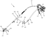
도 1은 본 발명에 의한 예초기를 도시한 사시도,
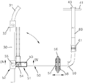
도 2는 본 발명에 의한 예초기의 요부를 발췌하여 도시한 분리 사시도,
도 3은 본 발명에 의한 예초기의 요부를 발췌하여 도시한 평면도,
도 4는 도 3의 Ⅳ-Ⅳ선을 따라 취한 단면도,
도 5는 본 발명에 의한 예초기의 사용상태를 개략적으로 도시한 측면도이다.1 is a perspective view showing a mower according to the present invention,
Figure 2 is an exploded perspective view showing the main parts of the lawn mower according to the present invention,
Figure 3 is a plan view showing the main parts of the lawn mower according to the present invention,
4 is a cross-sectional view taken along line IV-IV of FIG. 3,
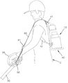
5 is a side view schematically showing a use state of the mower according to the present invention.
이와 같은 본 발명에 의한 예초기의 구체적 특징과 다른 이점들은 첨부된 도면을 참조한 이하의 바람직한 실시 예들의 설명으로 더욱 명확해질 것이다.Such specific features and other advantages of the lawn mower according to the present invention will be further clarified by the following description of preferred embodiments with reference to the accompanying drawings.
도 1 내지 도 5에서, 본 발명에 의한 예초기(1)는 동력발생유닛(10)과, 동력발생유닛(10)에 의해 구동되는 커터(22)를 갖는 헤드유닛(20)과, 이 헤드유닛(20)을 선단에 구비하는 조작로드(30)와, 이 조작로드(30)에 내장되어 동력발생부유닛(10)의 동력을 헤드유닛(20)의 커터(22)에 전달하는 동력전달유닛(도시하지 않음) 및 동력발생유닛(10)을 작업자(U)의 등에 짊어질 수 있도록 장착하는 캐리어랙(carrier rack:40)과, 조작로드(30)에 소정각도로 연결되는 보조 조작로드(50) 및 이 보조 조작로드(50)와 캐리어랙(40)간에 설치되어 작업자(U)의 어깨에 걸치지는 지지벨트(60)를 포함하여 구성된다.1 to 5, the
동력발생유닛(10)은 내연기관이나 모터로 이루어질 수 있다. 이 동력발생유닛(10)은 작업자(U)의 등에 짊어질 수 있도록 프레임(41)에 2개의 멜방(42)을 갖는 대략 지게 형태의 캐리어랙(40)에 장착된다.The
헤드유닛(20)은 조작로드(30)의 선단에 일체적으로 장착된다. 헤드유닛(20)은 동력발생유닛(10)에 의해 고속으로 회전하는 회전축(21)을 구비하고, 이 회전축(21)에 잔디나 풀을 깎을 수 있는 커터(22)를 갖는다. 커터(22)는 도시된 바와 같이 금속재 칼날로 구성될 수도 있고, 도시하지는 않았으나 나일론과 같은 합성수지재 와이어로 구성될 수도 있다.The
조작로드(30)는 작업자(U)가 기립한 상태로 이동하면서 헤드유닛(20)을 콘트롤 할 수 있도록 길게 구성되는 파이프로 이루어진다. 이 조작로드(30)는 자유로운 유동이 가능하도록 후단(상단)이 일정길이의 케이블(31)을 통해 동력발생유닛(10)에 연결되고, 소정위치에 동력발생유닛(10)의 구동을 제어하기 위한 스위치(32)를 구비한다.The
바람직하기로 이러한 조작로드(30)의 선단(하단)부 근처에는 작업 중 이물질이 작업자(U)에게 비산하는 것을 방지하기 위한 안전커버(33)가 구비될 수 있다.Preferably, a
한편, 보조 조작로드(50)는 조작로드(30)와 소정각도, 예를 들어 대략 직교하도록 연결될 수 있다. 이 보조 조작로드(50)는 작업자(U)가 어느 한 손, 예컨대 왼손으로 자연스럽게 파지할 수 있을 정도의 길이로 구성된다. 이러한 보조 조작로드(50)는 작업자(U)가 가장 편한 자세로 파지할 수 있도록 조작로드(30)에 대해 절첩 가능하게 연결되는 것이 바람직한데, 이 경우 보관도 매우 용이해지게 된다.Meanwhile, the
이를 위해 보조 조작로드(50)는 힌지홀더()를 통해서 조작로드(30)에 연결된다. 힌지홀더(51)는 여러 형태로 구성될 수 있는데, 예를 들어 도시된 바와 같이 조작로드(30)를 삽입하는 고정홀더(52)와, 이 고정홀더(52)에 피벗 연결되는 회동홀더(53)로 이루어질 수 있다.To this end, the
고정홀더(52)는 외주에 힌지러그(hinge lug:52a)를 돌출되게 가지며, 회동홀더(53)는 일단에 힌지러그(52a)가 끼워지는 힌지포크(hinge fork:53a)를 구비하여 양자가 힌지핀(54)으로 연결됨으로써 회동 가능하다.The fixed
회동홀더(53)는 타단에 나사구멍(53b)을 구비하여 보조 조작로드(50)의 일단에 구비된 나사부(50a)와 결합됨으로써 보조 조작로드(50)를 조작로드(30)에 대해 절첩시킬 수 있다.
여기서, 보다 바람직하기로는 힌지홀더(51)의 고정홀더(52)가 조작로드(30)를 이동 및 회동 가능한 상태로 삽입하고, 외주에 나사구멍(52b)을 구비하여서 이 나사구멍(52b)에 고정노브(55)를 체결함으로써 조작로드(30)에 대해 위치고정 및 고정해제 시킬 수 있다.Here, more preferably, the fixed
이 경우, 작업자(U)의 신체조건이나 취향 등에 따라서 보조 조작로드(50)의 위치를 원하는 위치로 자유롭게 조절할 수 있으며, 이에 따라 작업자(U)가 자신에게 가장 적합하게 세팅하여 지극히 편안한 파지상태를 구현할 수 있게 된다.In this case, the position of the
그리고 보조 조작로드(50)의 자유단 쪽에는 보조 조작로드(50)를 보다 용이하게 파지할 수 있도록 원호형의 핸들(56)이 구비되는 것이 바람직한데, 이 핸들(56)은 보조 조작로드(50)에 대해 고정위치를 가변시킬 수 있도록 클램프(57)에 의해 고정된다.In addition, it is preferable that the
이를 위해 클램프(57)는 예컨대 핸들(56)과 일체로 구성되어 보조 조작로드(50)의 일부를 감싸주는 상부 클램프(57a)와, 상부 클램프(57a)와 별도로 구성되어 보조 조작로드(50)의 일부를 감싸주면서 상부 클램프(57a)와 나사(58)로 체결되는 하부 클램프(57b)로 구성될 수 있다.To this end, the
지지벨트(60)는 작업자(U)가 동력발생유닛(10)을 등에 짊어졌을 때, 작업자(U)의 한쪽 어깨에 걸쳐짐으로써 조작로드(30)의 중량을 분산 감당할 수 있어야 하는 바, 일단이 캐리어랙(40)의 프레임(41) 상단에 연결되고 타단은 보조 조작로드(50)의 자유단쪽에 연결된다.The
이때, 예초작업 중 지지벨트(60)가 작업자(U)의 어깨로부터 이탈되지 않고 안정되게 지탱할 수 있도록 지지벨트(60)의 타단은 보조 조작로드(50)의 핸들(56)과 조작로드(30) 사이에 위치하는 것이 바람직하다.At this time, the other end of the
이러한 지지벨트(60) 역시 작업자(U)의 신체조건 등에 따라 그 길이를 적절히 조절할 수 있는 것이 바람직한 바, 지지벨트(60)는 충분히 긴 길이로 구성되어 버클(61)을 통해 적절한 길이로 조정될 수 있다.The
나머지 부호 43과 59는 지지벨트(60)를 위치 고정시키기 위해 캐리어랙(40) 프레임(41)과 보조 조작로드(50)에 구비된 걸고리이다.The rest of the
이와 같은 구조적 특징을 가지는 본 발명에 의한 예초기(1)는, 예컨대 작업자(U)가 오른손으로 조작로드(30)의 상단부를 잡고, 왼손으로 보조 조작로드(50)의 핸들(56)을 파지하게 되는데, 보조 조작로드(50)는 조작로드(30)에 대해 교차하는 방향으로 연장되어 있으므로 작업자(U)가 지극히 자연스럽고 편안한 자세로 파지할 수 있게 된다.
아울러, 보조 조작로드(50)의 자유단쪽과 캐리어랙(40)의 상단간에 연결된 지지벨트(60)가 작업자(U)의 왼쪽 어깨 위에 걸쳐지는 바, 조작로드(30)의 중량 대부분이 작업자(U)의 어깨부위에 의해 지탱되게 된다.In addition, the
따라서 작업자(U)는 종래와 달리 매우 편안한 상태에서 최소한의 힘으로 조작로드(30)를 용이하고 안정되게 콘트롤 할 수 있으며, 이에 따라 장시간 작업에도 피로를 최소화 할 수 있음은 물론 예초대상물도 깔끔하게 자를 수 있게 된다.Therefore, the operator U can easily and stably control the
이상에서 설명하고 도시한 바와 같은 본 발명은 상기의 실시예에 한정하는 취지는 아니며 본 발명의 요지를 벗어나지 않는 범위 내에서 다양한 형태로 실시될 수 있을 것이다. 예를 들어 보조 조작로드를 조작로드에 조립하기 위한 힌지홀더나 보조 조작로드에 장착되는 손잡이 및 지지벨트 등은 그 구성에 있어서 다양한 형태의 적용이나 변경이 가능할 것이다.The present invention as described and illustrated above is not intended to be limited to the above embodiments and may be implemented in various forms without departing from the gist of the present invention. For example, a hinge holder for assembling the auxiliary operation rod to the operation rod or a handle and a support belt mounted on the auxiliary operation rod may be applied or changed in various forms in its configuration.
1 : 예초기
10 : 동력발생유닛
20 : 헤드유닛
22 : 커터
30 : 조작로드
40 : 캐리어랙
41 : 프레임
42 ; 멜방
50 : 보조 조작로드
51 : 힌지홀더
52 : 고정홀더
53 : 회동홀더
55 : 고정노브
56 : 핸들
57 : 클램프
60 : 지지벨트
61 : 버클
U : 작업자1: Mower 10: Power generating unit
20: head unit 22: cutter
30: operation rod 40: carrier rack
41:
50: auxiliary operation rod 51: hinge holder
52: fixed holder 53: rotating holder
55: fixed knob 56: handle
57: clamp 60: support belt
61: buckle U: worker
Claims (4)
상기 조작로드에 소정각도 방향으로 연결되어서 작업자가 어느 한 손으로 파지할 수 있는 보조 조작로드;
상기 캐리어랙의 상단에 일단이 연결되고, 상기 보조 조작로드에 타단이 연결되어서 작업자의 어깨에 걸쳐지는 지지벨트;를 포함하는 것을 특징으로 하는 예초기
The power generating unit is provided with a power generating unit, a head unit having a cutter driven by the power generating unit, an operation rod connected to the power generating unit and a cable by providing the head unit at a front end, and a melbang. In the mower comprising a carrier rack to be mounted,
An auxiliary operation rod that is connected to the operation rod in a predetermined angle direction so that an operator can grip it with one hand;
One end is connected to the top of the carrier rack, the other end is connected to the auxiliary operation rod, the support belt spanning the shoulder of the operator; characterized in that it comprises a
상기 보조 조작로드가 힌지홀더를 통해 상기 조작로드에 연결되어서 상기 조작로드에 대해 절첩 가능한 것을 특징으로 하는 예초기
The method according to claim 1,
A mower characterized in that the auxiliary operation rod is connected to the operation rod through a hinge holder and can be folded relative to the operation rod.
상기 조작로드에 결합되는 고정홀더와, 상기 고정홀더에 피벗 연결되어서 상기 보조 조작로드와 연결되는 회동홀더로 이루어지며, 상기 고정홀더가 상기 조작로드를 이동 가능하게 삽입하고, 상기 고정홀더를 상기 조작로드에 대해 위치 고정 및 고정 해제시키는 고정노브를 더 구비하는 것을 특징으로 하는 예초기.
The method according to claim 2, The hinge holder,
It consists of a fixed holder coupled to the operation rod, and a pivot holder connected to the auxiliary operation rod pivotally connected to the fixed holder, the fixed holder movably inserting the operation rod, and operating the fixed holder A mower further comprising a fixing knob for fixing and releasing the position relative to the rod.
상기 보조 조작로드에 용이한 파지를 위한 핸들이 구비된 것을 특징으로 하는 예초기.
The method according to any one of claims 1 to 3,
A mower characterized in that the auxiliary operation rod is provided with a handle for easy gripping.
Priority Applications (1)
| Application Number | Priority Date | Filing Date | Title |
|---|---|---|---|
| KR1020180137841A KR20200054509A (en) | 2018-11-12 | 2018-11-12 | Mower |
Applications Claiming Priority (1)
| Application Number | Priority Date | Filing Date | Title |
|---|---|---|---|
| KR1020180137841A KR20200054509A (en) | 2018-11-12 | 2018-11-12 | Mower |
Publications (1)
| Publication Number | Publication Date |
|---|---|
| KR20200054509A true KR20200054509A (en) | 2020-05-20 |
Family
ID=70919648
Family Applications (1)
| Application Number | Title | Priority Date | Filing Date |
|---|---|---|---|
| KR1020180137841A KR20200054509A (en) | 2018-11-12 | 2018-11-12 | Mower |
Country Status (1)
| Country | Link |
|---|---|
| KR (1) | KR20200054509A (en) |
Cited By (3)
| Publication number | Priority date | Publication date | Assignee | Title |
|---|---|---|---|---|
| KR20210157066A (en) | 2020-06-19 | 2021-12-28 | 농업회사법인 와이즈팜 주식회사 | Wireless moving vehicles for multipurpose grass mowers |
| KR20220016633A (en) * | 2020-08-03 | 2022-02-10 | 우기중 | Handler assembly for brush cutter |
| KR20220028719A (en) * | 2020-08-31 | 2022-03-08 | 김재희 | A device for handling a trimmer |
Citations (4)
| Publication number | Priority date | Publication date | Assignee | Title |
|---|---|---|---|---|
| KR101189569B1 (en) | 2010-01-26 | 2012-10-10 | 주식회사 홈앤가든 | Nylon Cutter Mounting Head of Grass Cutter |
| KR200474494Y1 (en) | 2014-03-21 | 2014-09-22 | 대성하이텍 주식회사 | Buoyancy device of grass cutting blade |
| KR101795453B1 (en) | 2016-06-20 | 2017-12-01 | 이정희 | Cutter assembly for grass cutter |
| KR101868268B1 (en) | 2017-02-01 | 2018-06-15 | 신연철 | Cutter assembly of lawn mower having four lines |
-
2018
- 2018-11-12 KR KR1020180137841A patent/KR20200054509A/en not_active IP Right Cessation
Patent Citations (4)
| Publication number | Priority date | Publication date | Assignee | Title |
|---|---|---|---|---|
| KR101189569B1 (en) | 2010-01-26 | 2012-10-10 | 주식회사 홈앤가든 | Nylon Cutter Mounting Head of Grass Cutter |
| KR200474494Y1 (en) | 2014-03-21 | 2014-09-22 | 대성하이텍 주식회사 | Buoyancy device of grass cutting blade |
| KR101795453B1 (en) | 2016-06-20 | 2017-12-01 | 이정희 | Cutter assembly for grass cutter |
| KR101868268B1 (en) | 2017-02-01 | 2018-06-15 | 신연철 | Cutter assembly of lawn mower having four lines |
Cited By (3)
| Publication number | Priority date | Publication date | Assignee | Title |
|---|---|---|---|---|
| KR20210157066A (en) | 2020-06-19 | 2021-12-28 | 농업회사법인 와이즈팜 주식회사 | Wireless moving vehicles for multipurpose grass mowers |
| KR20220016633A (en) * | 2020-08-03 | 2022-02-10 | 우기중 | Handler assembly for brush cutter |
| KR20220028719A (en) * | 2020-08-31 | 2022-03-08 | 김재희 | A device for handling a trimmer |
Similar Documents
| Publication | Publication Date | Title |
|---|---|---|
| US4829755A (en) | Trimmer wheels | |
| US4282652A (en) | Apparatus for cutting vegetation | |
| KR101055715B1 (en) | Mowing machine | |
| US5095687A (en) | Adjustable support wheel asssembly for rotating flexible line-type vegetation trimmer | |
| US5265341A (en) | Battery powered line trimmer arm rest | |
| US6880251B2 (en) | Powered trimmer | |
| US5450715A (en) | Wheel assembly for grass trimmers and the like | |
| US4483070A (en) | Portable backpacked cutter | |
| US5263303A (en) | Lawn edger using flexible filament cutting line | |
| KR20200054509A (en) | Mower | |
| US9931746B2 (en) | Handle configuration for power implements | |
| MX2011000416A (en) | Mechanized portable electric tool with two shafts. | |
| JPH10150825A (en) | Portable bush cutter | |
| US5697453A (en) | Subsurface cutting tool | |
| JP3622646B2 (en) | Hedge trimmer | |
| US20100031515A1 (en) | Grounds tool with means for transposable grips | |
| US20140260839A1 (en) | Powered grounds tool supporting handle | |
| US20100000097A1 (en) | Weed trimming device | |
| US6675565B2 (en) | Weedcutting machine | |
| CA3006520A1 (en) | Adjustable field trimmer | |
| JPH07194223A (en) | Mechanical type rake | |
| US5048615A (en) | Weed and grass trimmer | |
| KR200404883Y1 (en) | Weeder | |
| AU2020100005A4 (en) | Line trimmer assembly | |
| KR20050028231A (en) | Saddle for potable cutter |
Legal Events
| Date | Code | Title | Description |
|---|---|---|---|
| E902 | Notification of reason for refusal | ||
| AMND | Amendment | ||
| E601 | Decision to refuse application | ||
| AMND | Amendment | ||
| E902 | Notification of reason for refusal | ||
| X601 | Decision of rejection after re-examination |