KR20200053300A - Negative electrode for lithium secondary battery, method of preparing the saem, and lithium secondary battery using the same - Google Patents
Negative electrode for lithium secondary battery, method of preparing the saem, and lithium secondary battery using the same Download PDFInfo
- Publication number
- KR20200053300A KR20200053300A KR1020180136752A KR20180136752A KR20200053300A KR 20200053300 A KR20200053300 A KR 20200053300A KR 1020180136752 A KR1020180136752 A KR 1020180136752A KR 20180136752 A KR20180136752 A KR 20180136752A KR 20200053300 A KR20200053300 A KR 20200053300A
- Authority
- KR
- South Korea
- Prior art keywords
- negative electrode
- lithium
- secondary battery
- lithium secondary
- active material
- Prior art date
Links
Images


Classifications
-
- H—ELECTRICITY
- H01—ELECTRIC ELEMENTS
- H01M—PROCESSES OR MEANS, e.g. BATTERIES, FOR THE DIRECT CONVERSION OF CHEMICAL ENERGY INTO ELECTRICAL ENERGY
- H01M4/00—Electrodes
- H01M4/02—Electrodes composed of, or comprising, active material
- H01M4/13—Electrodes for accumulators with non-aqueous electrolyte, e.g. for lithium-accumulators; Processes of manufacture thereof
-
- H—ELECTRICITY
- H01—ELECTRIC ELEMENTS
- H01M—PROCESSES OR MEANS, e.g. BATTERIES, FOR THE DIRECT CONVERSION OF CHEMICAL ENERGY INTO ELECTRICAL ENERGY
- H01M10/00—Secondary cells; Manufacture thereof
- H01M10/05—Accumulators with non-aqueous electrolyte
- H01M10/052—Li-accumulators
-
- H—ELECTRICITY
- H01—ELECTRIC ELEMENTS
- H01M—PROCESSES OR MEANS, e.g. BATTERIES, FOR THE DIRECT CONVERSION OF CHEMICAL ENERGY INTO ELECTRICAL ENERGY
- H01M4/00—Electrodes
- H01M4/02—Electrodes composed of, or comprising, active material
- H01M4/04—Processes of manufacture in general
-
- H—ELECTRICITY
- H01—ELECTRIC ELEMENTS
- H01M—PROCESSES OR MEANS, e.g. BATTERIES, FOR THE DIRECT CONVERSION OF CHEMICAL ENERGY INTO ELECTRICAL ENERGY
- H01M4/00—Electrodes
- H01M4/02—Electrodes composed of, or comprising, active material
- H01M4/04—Processes of manufacture in general
- H01M4/0438—Processes of manufacture in general by electrochemical processing
- H01M4/0459—Electrochemical doping, intercalation, occlusion or alloying
- H01M4/0461—Electrochemical alloying
-
- H—ELECTRICITY
- H01—ELECTRIC ELEMENTS
- H01M—PROCESSES OR MEANS, e.g. BATTERIES, FOR THE DIRECT CONVERSION OF CHEMICAL ENERGY INTO ELECTRICAL ENERGY
- H01M4/00—Electrodes
- H01M4/02—Electrodes composed of, or comprising, active material
- H01M4/13—Electrodes for accumulators with non-aqueous electrolyte, e.g. for lithium-accumulators; Processes of manufacture thereof
- H01M4/131—Electrodes based on mixed oxides or hydroxides, or on mixtures of oxides or hydroxides, e.g. LiCoOx
-
- H—ELECTRICITY
- H01—ELECTRIC ELEMENTS
- H01M—PROCESSES OR MEANS, e.g. BATTERIES, FOR THE DIRECT CONVERSION OF CHEMICAL ENERGY INTO ELECTRICAL ENERGY
- H01M4/00—Electrodes
- H01M4/02—Electrodes composed of, or comprising, active material
- H01M4/13—Electrodes for accumulators with non-aqueous electrolyte, e.g. for lithium-accumulators; Processes of manufacture thereof
- H01M4/133—Electrodes based on carbonaceous material, e.g. graphite-intercalation compounds or CFx
-
- H—ELECTRICITY
- H01—ELECTRIC ELEMENTS
- H01M—PROCESSES OR MEANS, e.g. BATTERIES, FOR THE DIRECT CONVERSION OF CHEMICAL ENERGY INTO ELECTRICAL ENERGY
- H01M4/00—Electrodes
- H01M4/02—Electrodes composed of, or comprising, active material
- H01M4/13—Electrodes for accumulators with non-aqueous electrolyte, e.g. for lithium-accumulators; Processes of manufacture thereof
- H01M4/134—Electrodes based on metals, Si or alloys
-
- H—ELECTRICITY
- H01—ELECTRIC ELEMENTS
- H01M—PROCESSES OR MEANS, e.g. BATTERIES, FOR THE DIRECT CONVERSION OF CHEMICAL ENERGY INTO ELECTRICAL ENERGY
- H01M4/00—Electrodes
- H01M4/02—Electrodes composed of, or comprising, active material
- H01M4/13—Electrodes for accumulators with non-aqueous electrolyte, e.g. for lithium-accumulators; Processes of manufacture thereof
- H01M4/139—Processes of manufacture
-
- Y—GENERAL TAGGING OF NEW TECHNOLOGICAL DEVELOPMENTS; GENERAL TAGGING OF CROSS-SECTIONAL TECHNOLOGIES SPANNING OVER SEVERAL SECTIONS OF THE IPC; TECHNICAL SUBJECTS COVERED BY FORMER USPC CROSS-REFERENCE ART COLLECTIONS [XRACs] AND DIGESTS
- Y02—TECHNOLOGIES OR APPLICATIONS FOR MITIGATION OR ADAPTATION AGAINST CLIMATE CHANGE
- Y02E—REDUCTION OF GREENHOUSE GAS [GHG] EMISSIONS, RELATED TO ENERGY GENERATION, TRANSMISSION OR DISTRIBUTION
- Y02E60/00—Enabling technologies; Technologies with a potential or indirect contribution to GHG emissions mitigation
- Y02E60/10—Energy storage using batteries
Abstract
Description
리튬 이차 전지용 음극, 이의 제조 방법 및 이를 이용한 리튬 이차 전지에 대한 것이다. A negative electrode for a lithium secondary battery, a method for manufacturing the same, and a lithium secondary battery using the same.
고에너지밀도 리튬 이차 전지의 수요의 증가에 따라, 음극 활물질로 탄소계 물질 보다 10배 이상의 유효 용량을 가지는 규소계 및/또는 규소산화계 물질의 사용이 증대되고 있다. As the demand for high-energy-density lithium secondary batteries increases, the use of silicon-based and / or silicon oxide-based materials having an effective capacity of 10 times or more as carbon-based materials as the negative electrode active material is increasing.
규소계 물질은 용량이 매우 높은 장점이 있으나, 충방전 중 체적 변화가 심하여 부피 팽창에 의한 크랙 및 분체화 문제가 있어, 단독으로 사용하기 어려우며 소량을 탄소계 물질에 첨가하여 복합 음극재로 사용한다. 규소산화계 물질은 규소계 물질 대비 용량은 낮지만, 부피팽창률이 상대적으로 작아 내구성이 우수하여 복합 음극재로 사용될 경우 규소 산화계 물질의 함량을 높일 수 있어 유효 용량의 증가를 기대할 수 있다. The silicon-based material has an advantage of a very high capacity, but there is a problem of cracking and powdering due to volume expansion due to a large volume change during charging and discharging. . The silicon oxide-based material has a lower capacity than the silicon-based material, but the volume expansion coefficient is relatively small, so it is excellent in durability, and when used as a composite anode material, it is possible to increase the content of the silicon oxide-based material, thus increasing the effective capacity.
한편, 리튬 이온 전지는 최초 충전 과정 중 음극에서 고체 전해질 계면 (solid electrolyte interface: SEI)이 형성될 뿐만 아니라, 비가역적인 리튬 도금 및 부반응 등에 의하여 활성리튬의 손실 (Active Lithium Loss)이 발생되어 실제 가역 용량이 감소되는 현상이 나타나며, 이를 초기 비가역 현상이라 부른다. On the other hand, the lithium ion battery not only forms a solid electrolyte interface (SEI) at the negative electrode during the initial charging process, but also generates active lithium losses due to irreversible lithium plating and side reactions. A phenomenon in which the capacity is reduced appears, and this is called an initial irreversible phenomenon.
이와 같은 초기 비가역 현상은 탄소계 음극 활물질 대비 규소계 물질 또는 규소 산화계 물질을 음극 활물질로 사용하였을 때 두드러지게 나타나며, 특히 규소 산화계 물질의 경우에는 활물질 내에 산소가 존재함에 따라 Li2O, Li4SiO 등의 비가역 물질의 생성이 용이하여 초기 비가역 현상이 더욱 심하게 나타나, 결과적으로 초기 쿨롱 효율(ICE, Initial Columb Efficiency)이 70% 수준으로 매우 낮은 문제가 있다.This initial irreversible phenomenon is prominent when a silicon-based material or a silicon oxide-based material is used as a negative electrode active material compared to a carbon-based negative electrode active material, and in particular, in the case of a silicon oxide-based material, as oxygen is present in the active material, Li 2 O, Li 4 SiO It is easy to generate irreversible materials such as the initial irreversible phenomenon more severe, and as a result, there is a problem that the initial coulomb efficiency (ICE, Initial Columb Efficiency) is very low at 70%.
따라서, 고용량의 규소계 및 규소산화계 물질을 리튬 이온전지의 음극재로 사용하기 위해서는 초기 충전 과정 중에 발생하는 리튬의 손실을 사전에 보상해 주는 것이 필수적이며 이러한 과정을 전리튬화(pre-lithiation)라 부른다.Therefore, in order to use high-capacity silicon-based and silicon-oxide-based materials as negative electrode materials for lithium ion batteries, it is essential to compensate for the loss of lithium generated during the initial charging process in advance, and pre-lithiation of these processes I call it.
전리튬화는 리튬을 보상하는 위치에 따라 양극재 전리튬화 및 음극재 전리튬화로 나뉠 수 있다. 양극재 전리튬화는 과리튬화된(over-lithiated) 양극재 또는 Li2NiO2와 같은 고용량 양극재를 첨가제로 사용하는 것으로, 공정상 간단한 장점이 있으나, 용량 증가의 효과가 제한적이고, 리튬을 보상한 후에 완전 분해되지 않고 남기 때문에 무게 증가 및 전해액과의 부반응을 유발하는 문제가 있다. 뿐만 아니라 상기의 양극재 첨가제는 슬러리 제작시 겔화 반응이 발생하거나 분해 과정을 통해 다량의 가스가 발생하는 문제가 있다.The pre-lithiation can be divided into the pre-lithiation of the positive electrode material and the pre-lithiation of the negative electrode material depending on the position to compensate for lithium. Cathode material pre-lithiation is the use of an over-lithiated cathode material or a high-capacity cathode material such as Li 2 NiO 2 as an additive, which has a simple process advantage, but the effect of capacity increase is limited, and lithium After compensating for, there is a problem of causing weight gain and side reaction with the electrolyte because it remains without decomposition. In addition, the positive electrode material additive has a problem in that a large amount of gas is generated through a gelation reaction or a decomposition process during slurry production.
한편, 음극재 전리튬화는 양극재 전리튬화에 비하여 더욱 다양한 방법으로 개발되고 있다. 예를 들어, 음극재를 제조하는 단계부터 안정화된 리튬 금속 분말 (Stabilized Lithium Metal Powder, SLMP) 또는 원료 합성 단계에서 이미 리튬과 반응이 완료된 리튬규소산화물(LixSiO)을 첨가함으로써 리튬을 보상하는 방법이 있다. 그러나, 이와 같은 방법에 사용되는 첨가 물질은 매우 고가이며 음극재 내의 전영역에 걸쳐 균일하게 분포시키는데 제약이 따른다. On the other hand, the pre-lithiation of the anode material has been developed in more various ways than the pre-lithiation of the cathode material. For example, to compensate for lithium by adding stabilized lithium metal powder (SLMP) from the step of manufacturing the anode material or lithium silicon oxide (Li x SiO), which has already been reacted with lithium in the raw material synthesis step. There is a way. However, the additive material used in this method is very expensive and there is a limitation in uniformly distributing it over the entire area in the negative electrode material.
제조가 이미 완료된 음극재를 리튬 이온 전지로 조립되기 전에 전해액에 침지된 상태로 리튬 금속과 직접 접촉시키거나 전기화학적 방법을 통하여 외부에서 리튬원을 음극재에 공급해 줌으로써, 음극재에서 일어나는 초기 비가역 반응을 전지 조립 전에 완성하여 전지 조립 이후에는 비가역 반응이 발생되지 않도록 하는 방법이 있다. 이와 같은 방법은 전리튬화 이후 전지 조립 전에 음극재를 분리하고 전해액을 세척해야 하는 문제가 있다.The initial irreversible reaction occurring in the negative electrode material by directly contacting the lithium metal in a state of being immersed in an electrolyte before assembling the negative electrode material that has already been manufactured into a lithium ion battery or by supplying a lithium source to the negative electrode material externally through an electrochemical method There is a method that is completed before the battery assembly, so that irreversible reaction does not occur after the battery assembly. This method has a problem in that the negative electrode material must be separated and the electrolytic solution washed before battery assembly after pre-lithiation.
상술한 바와 같이 전리튬화의 위치, 전리튬화의 단계 및 방법 등에 따라 각각 장점 및 단점을 가지고 있다. 그럼에도 불구하고 전리튬화 과정에서 반드시 갖추어야 할 요소로는 적정량의 리튬이 전리튬화가 되어야 하며, 전체 영역에서 균일하게 전리튬화가 이루어져야 한다. As described above, each has advantages and disadvantages depending on the location of pre-lithiation, the steps and methods of pre-lithiation, and the like. Nevertheless, as an essential element in the pre-lithiation process, an appropriate amount of lithium must be pre-lithiated, and uniformly pre-lithiated in all regions.
만약, 정량대비 미흡하게 전리튬화가 되면 초기 비가역 방지의 효과가 미미해 지며, 정량대비 과도하게 전리튬화가 되면 전지 작동 중 과량의 리튬이 음극 위에 도금됨으로써, 과충전과 같은 안전성의 문제를 유발할 수 있다. 이러한 문제는 전리튬화의 국부적 불균일에서도 나타날 수 있는 문제이므로 정량 및 균일성은 전리튬화에 있어 매우 중요한 요건이 된다.If the total amount of lithium is insufficiently quantified, the effect of initial irreversible prevention becomes insignificant, and if excessively pre-lithiated compared to quantitative, an excessive amount of lithium is plated on the negative electrode during operation, thereby causing safety problems such as overcharging. Since this problem can occur even in the local non-uniformity of pre-lithiation, quantitative and uniformity are very important requirements for pre-lithiation.
KR 10-2013-0090181에서는 음극재와 리튬 금속을 함께 감은 롤을 전해액 용액에 침지시키는 방법으로 음극 전극의 표면을 전리튬화 시키고자 하였다. In KR 10-2013-0090181, the surface of the negative electrode was pre-lithiated by immersing the roll in which the negative electrode material and lithium metal were wound together in an electrolyte solution.
그러나, 이와 같은 직접 접촉법에서는 전리튬화의 정도를 정확하게 제어할 수 없는 단점이 있다. 또한, 접촉되는 영역이 균일하지 않아 국부적으로 전리튬화의 정도가 차이가 발생되는 문제가 있다. However, such a direct contact method has a disadvantage that it is impossible to accurately control the degree of pre-lithiation. In addition, there is a problem in that the degree of pre-lithiation is locally different because the contacting region is not uniform.
이에 개선된 전리튬화 방법이 필요한 실정이다. Accordingly, there is a need for an improved method of pre-lithiation.
본 발명의 일 구현예에서는, 음극재, 특히 탄소계 물질 보다 10배 이상의 유효 용량을 가지는 규소계 및/또는 규소산화계 물질이 포함된 음극재의 전리튬화에 있어, 상업적으로 유용한 크기에 걸쳐 전 영역에서 균일하게 리튬이 보상될 뿐만 아니라, 보상된 리튬의 양이 정확하게 제어되어 있는 음극재를 확보하는 방법을 제안하고자 한다.In one embodiment of the present invention, in the pre-lithiation of a negative electrode material, especially a negative electrode material containing a silicon-based and / or silicon oxide-based material having an effective capacity of 10 times or more than a carbon-based material, the entire area over a commercially available size In order to propose a method for securing a negative electrode material in which not only lithium is uniformly compensated, but the amount of compensated lithium is accurately controlled.
본 발명의 일 구현예에서는, 집전체; 및 상기 집전체 상에 위치하는 음극 활물질층;을 포함하는 음극이되, 상기 음극 활물질층은 두께 방향으로 균일하게 전리튬화(pre-lithiation)된 것인 리튬 이차 전지용 음극을 제공한다. In one embodiment of the present invention, the current collector; And a negative electrode active material layer positioned on the current collector, wherein the negative electrode active material layer is uniformly pre-lithiated in the thickness direction to provide a negative electrode for a lithium secondary battery.
상기 음극 활물질의 전체 두께 방향에 대해 임의의 지점에서의 리튬의 함량은, 상기 음극 활물질층의 표면부에서부터 두께 방향으로 20길이% 내의 리튬 함량의 최소값 및 최대값의 범위 내의 값일 수 있다. 보다 구체적으로 설명하면, 음극의 두께 방향으로 표면부에서 집전체 하부까지의 리튬의 분포가 균일할 수 있다. 이에 대한 구체적인 실험적인 근거는 후술하는 실시예에서 보다 자세히 설명하도록 한다. The content of lithium at any point with respect to the entire thickness direction of the negative electrode active material may be a value within a range of a minimum and maximum value of lithium in 20% by length in the thickness direction from the surface portion of the negative electrode active material layer. More specifically, the distribution of lithium from the surface portion to the bottom of the current collector in the thickness direction of the negative electrode may be uniform. The detailed experimental basis for this will be described in more detail in the Examples to be described later.
상기 음극 활물질층의 표면은 리튬 도금층이 존재하지 않을 수 있다. 보다 구체적으로, 전리튬화가 과도하게 진행되어 표면에 리튬 도금층이 형성되는 수준으로는 수행되지 않는다. A surface of the negative electrode active material layer may not have a lithium plating layer. More specifically, it is not carried out at a level in which the lithium plating layer is formed on the surface because the pre-lithiation proceeds excessively.
상기 음극 활물질층 내 음극 활물질은, 규쇼계 화합물, 규소 산화물계 화합물, 탄소계 화합물, 또는 이들의 조합을 포함할 수 있다. 현재까지 알려진 다양한 복합체 형태의 실리콘계 음극 활물질이 사용될 수 있다. The negative electrode active material in the negative electrode active material layer may include a silicon-based compound, a silicon oxide-based compound, a carbon-based compound, or a combination thereof. Various types of composite silicon-based negative active materials known to date can be used.
상기 음극은, 상기 집전체 양면에 상기 음극 활물질층이 위치하는 구조일 수 있다. The negative electrode may have a structure in which the negative electrode active material layer is located on both sides of the current collector.
집전체는 전지 내에서 전기적 연결을 위한 것이다. The current collector is for electrical connection within the battery.
집전체는, 박막 (Foil)의 형태를 가질 수 있으나, 이에 한정되는 것은 아니며, 예를 들면, 메쉬 (mesh), 폼 (Foam), 봉재(rod), 선재(wire), 및 선재(wire, fiber)를 직조한 박판 (sheet)의 형태를 가질 수도 있다.The current collector may have the form of a thin film (Foil), but is not limited thereto, for example, a mesh (mesh), foam (Foam), rod (rod), wire (wire), and wire (wire, It may have the form of a sheet (woven) of fibers.
집전체의 소재로는 전기 전도성을 가지며 리튬과의 반응이 제한적인 소재를 사용할 수 있다. 집전체의 소재로는, 예를 들면, 구리, 니켈, 티타늄, 스테인레스강, 금, 백금, 은, 탄탈륨, 루테늄, 및 이들의 합금, 탄소, 도전성 폴리머, 비 도전성 폴리머 상에 도전층이 코팅된 복합 섬유 중 어느 하나 또는 이들의 조합을 사용할 수 있다. As the material of the current collector, a material having electrical conductivity and having limited reaction with lithium may be used. As a material of the current collector, for example, a conductive layer is coated on copper, nickel, titanium, stainless steel, gold, platinum, silver, tantalum, ruthenium, and alloys thereof, carbon, conductive polymer, and non-conductive polymer. Any one or a combination of the composite fibers can be used.
집전체의 두께가 두꺼우면 전지 중량이 증가되어 전지의 에너지밀도가 낮아지게 되며, 집전체의 두께가 얇아지면 고전류 작동시 과열 파손의 위험이 있고, 전지 제조 공정중 장력에 의해 파손될 수 있다. 따라서, 집전체의 두께는 1 ㎛ 내지 50 ㎛범위일 수 있다.If the thickness of the current collector is thick, the weight of the battery is increased and the energy density of the battery is lowered. If the thickness of the current collector is thin, there is a risk of overheat damage during high current operation and may be damaged by tension during the battery manufacturing process. Therefore, the thickness of the current collector may range from 1 μm to 50 μm.
상기 음극 활물질층의 두께는 10 내지 200㎛일 수 있다. 음극 활물질층이 너무 두꺼우면 전지의 두께 증가 대비 충분한 충전 효과를 보기가 어려우며, 박리의 문제가 발생할 수 있다. 너무 얇은 경우, 전지 특성이 저하될 우려가 있다. The negative active material layer may have a thickness of 10 to 200 μm. When the negative electrode active material layer is too thick, it is difficult to see a sufficient charging effect compared to an increase in the thickness of the battery, and peeling problems may occur. If it is too thin, there is a fear that battery characteristics may deteriorate.
상기 음극 활물질층 표면에 위치하는 피막을 더 포함할 수 있다. A film positioned on the surface of the negative electrode active material layer may be further included.
상기 피막은 상기 음극의 제조 과정에서, 전착된 리튬 금속과 도금액간의 반응 등으로 형성되는 것으로, 사용하는 도금액의 조성 및 전착 공정의 조건을 조절하여 피막의 두께 및 조성, 특성 등을 제어할 수 있다. The coating is formed by a reaction between the electrodeposited lithium metal and the plating solution in the manufacturing process of the negative electrode, and the thickness and composition, characteristics, etc. of the coating can be controlled by controlling the composition of the plating solution used and the conditions of the electrodeposition process. .
상기 피막의 두께는, 예를 들면, 2nm 내지 2㎛, 보다 구체적으로 10nm 내지 500nm 범위일 수 있다. The thickness of the coating may be, for example, 2 nm to 2 μm, more specifically 10 nm to 500 nm.
음극의 표면에 위치하는 상기 피막의 두께가 너무 두꺼우면 리튬 이온 전도도가 낮아지고 계면 저항이 증가하여 전지 적용시 충방전 특성이 저하될 수 있다. 또한, 피막의 두께가 너무 얇으면 실시예에 따른 음극을 전지에 적용하는 과정에서 피막이 쉽게 유실될 수 있다.When the thickness of the coating located on the surface of the negative electrode is too thick, lithium ion conductivity is lowered and interface resistance is increased, so that charge / discharge characteristics may be deteriorated when the battery is applied. In addition, if the thickness of the coating is too thin, the coating may be easily lost in the process of applying the negative electrode according to the embodiment to the battery.
따라서, 상기 피막은, 상기 두께 범위를 만족하는 범위에서, 얇은 두께로, 음극 표면 전체에 균일하고 치밀하게 형성되는 것이 바람직하다. Therefore, it is preferable that the coating is formed to be uniform and dense on the entire surface of the cathode, with a thin thickness, in a range that satisfies the thickness range.
상기 피막은 Li-N-C-H-O계 이온성 화합물, Li-P-C-H-O계 이온성 화합물, LiF 또는 이들의 조합일 수 있다. 전술한 바와 같이 피막의 조성은 전해액의 첨가제 및 전해액의 조성으로 제어될 수 있다. The coating may be a Li-N-C-H-O based ionic compound, a Li-P-C-H-O based ionic compound, LiF or a combination thereof. As described above, the composition of the film can be controlled by the additives of the electrolyte solution and the composition of the electrolyte solution.
구체적인 예를 들어, 상기 피막은 Li-N-C-H-O계 이온성 화합물을 포함한다. For a specific example, the coating includes a Li-N-C-H-O-based ionic compound.
본 실시예에서는, 전착 (Electroplating) 공정으로 음극을 전리튬화하는 과정에서, 도금액의 조성 및 함량을 조절함으로써, 상기 Li-N-C-H-O계 이온성 화합물을 포함하는 피막을 형성할 수 있다. In this embodiment, in the process of pre-lithiating the negative electrode by an electrodeposition (Electroplating) process, by controlling the composition and content of the plating solution, a film containing the Li-N-C-H-O-based ionic compound can be formed.
상기 Li-N-C-H-O계 이온성 화합물은, Li-O, C-N, C-O, 및 C-H 결합을 포함할 수 있다.The Li-N-C-H-O-based ionic compound may include Li-O, C-N, C-O, and C-H bonds.
보다 구체적으로, 상기 Li-N-C-H-O계 이온성 화합물은, 하기 화학식 1 내지 2 중 어느 하나로 표시되는 화합물을 포함할 수 있다.More specifically, the Li-N-C-H-O-based ionic compound may include a compound represented by any one of the following Chemical Formulas 1 to 2.
[화학식 1][Formula 1]
![]()
![]()
화학식 1에서, R1 및 R2는 각각 CHmF2 -m (m=0, 1, 2 중 하나)이고, In Formula 1, R 1 and R 2 are each CH m F 2 -m (m = 0, one of 1, 2),
A1은 

n1은 1 내지 10의 정수이다. n1 is an integer from 1 to 10.
[화학식 2][Formula 2]
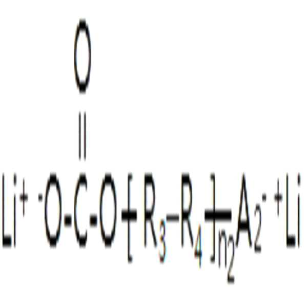
화학식 2에서, R3 및 R4는 각각 CHmF2 -m (m=0, 1, 2 중 하나)이고, In the formula (2), R 3 and R 4 are each CH m F 2 -m (m = 0, one of 1, 2),
A2는 

n2는 1 내지 10의 정수이다.n2 is an integer from 1 to 10.
보다 구체적으로, 예를 들어, 질소계 화합물로 질산 리튬 (Lithium nitrate, LiNO3)을 사용하고, 이를 에테르 (Ether)계 용매 (Solvent)에 적정 함량으로 첨가한 도금액을 이용하여 전리튬화 공정을 통해 음극을 전리튬화하는 경우, 음극의 표면에 상기 화학식 1 또는 2로 표시되는 화합물을 포함하는 피막이 형성될 수 있다.More specifically, for example, lithium nitrate (Lithium nitrate, LiNO 3 ) is used as a nitrogen-based compound, and the pre-lithiation process is performed using a plating solution in which an appropriate amount is added to an ether-based solvent (Solvent). When the negative electrode is pre-lithiated, a film containing the compound represented by
한편, 상기 피막은 Li-N-C-H-O계 이온성 화합물 외에 LiF를 더 포함할 수 있다. On the other hand, the coating may further include LiF in addition to the Li-N-C-H-O-based ionic compound.
보다 구체적으로, 예를 들어, 도금액에 포함되는 질소계 화합물로 리튬 비스 플루오로설포닐 이미드 (LiN(FSO2)2)를 사용하는 경우에는, 여기에 포함된 불소(F) 성분으로 인해 상기 피막은 Li-N-C-H-O계 이온성 화합물 외에 LiF를 더 포함할 수 있다. More specifically, for example, in the case of using lithium bis fluorosulfonyl imide (LiN (FSO 2 ) 2 ) as the nitrogen-based compound included in the plating solution, the fluorine (F) component contained therein may cause The coating may further include LiF in addition to the Li-NCHO-based ionic compound.
또한, 도금액에 플루오로에틸렌 카보네이트 (Fluoroethylene carbonate, FEC) 등과 같은 불소계 화합물을 더 포함시키는 경우에도 상기 피막(13)은 Li-N-C-H-O계 이온성 화합물과 함께 LiF를 포함할 수 있다.Further, even when a fluorine-based compound such as fluoroethylene carbonate (FEC) is further included in the plating solution, the film 13 may include LiF together with a Li-N-C-H-O-based ionic compound.
이와 같이, 상기 피막이 LiF를 더 포함하는 경우, Li-N-C-H-O계 이온성 화합물과의 상호작용으로 피막의 전기 화학적 성능을 보다 향상시킬 수 있다.As described above, when the film further includes LiF, the electrochemical performance of the film may be further improved by interaction with a Li-N-C-H-O-based ionic compound.
본 실시예와 같이, Li-N-C-H-O계 이온성 화합물을 포함하는 피막을 포함하는 음극을 리튬 이차 전지에 적용하는 경우, 전해액과 전리튬화된 음극 간의 부반응을 차단할 수 있다. 또한, 음극 표면에서 리튬의 탈착과 부착을 균일하게 하여 수지상 (Dendrite) 성장을 억제함으로써 리튬 이차 전지의 충방전 수명을 향상시킬 수 있다. As in this embodiment, when a negative electrode including a film containing a Li-N-C-H-O-based ionic compound is applied to a lithium secondary battery, side reactions between the electrolyte and the pre-lithiated negative electrode can be blocked. In addition, charging and discharging life of the lithium secondary battery can be improved by uniformly desorbing and adhering lithium on the surface of the negative electrode to suppress dendritic growth.
본 발명의 다른 일 구현예에서는, 전해액 내에 함침된, 음극 및 이에 대향하는 리튬 전극을 준비하는 단계; 및 상기 음극 및 리튬 전극에 전류를 인가하여, 상기 음극을 전리튬화(pre-lithiation)시키는 단계;를 포함하고, 상기 음극 및 리튬 전극의 간격은, 0 초과 및 1,500㎛ 이하인 것인 리튬 이차 전지용 음극의 제조 방법을 제공한다. In another embodiment of the present invention, the step of preparing a negative electrode and a lithium electrode opposed thereto, impregnated in the electrolyte solution; And applying a current to the negative electrode and the lithium electrode, thereby pre-lithiating the negative electrode; wherein the interval between the negative electrode and the lithium electrode is greater than 0 and less than 1,500 μm for a lithium secondary battery. Provided is a method of manufacturing a cathode.
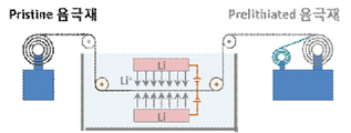
도 1은 본 발명의 일 구현예에 따른 전리튬화를 위한 장치의 개략도이다. 1 is a schematic diagram of an apparatus for pre-lithiation according to an embodiment of the present invention.
도 1과 같은 전리튬화 장치에 있어, 음극재 표면과 리튬 전극(예를 들어 리튬 금속 전극) 간의 간격을 일정하게 유지하기 위하여 평판형 리튬 전극을 적용할 수 있다. In the pre-lithiation apparatus as shown in FIG. 1, a flat-type lithium electrode may be applied to maintain a constant distance between the surface of the negative electrode material and the lithium electrode (for example, a lithium metal electrode).
음극재 표면과 리튬 전극 간의 간격이 작을수록 더욱 균일한 전류인가를 얻을 수 있으나, 간격이 너무 좁아져 직접 접촉될 경우에는 직접 접촉된 부위와 그렇지 않은 부위의 전류 흐름의 큰 차이를 유발하게 되어 전리튬화 정도의 차이를 유발할 뿐만 아니라, 음극재 표면 중심으로만 전리튬화가 일어날 수 있다. The smaller the gap between the surface of the anode material and the lithium electrode, the more uniform current application can be obtained. However, if the gap is too narrow to make direct contact, it causes a large difference in current flow between the direct contact area and the non-contact area. In addition to causing a difference in the degree of lithiation, pre-lithiation can occur only at the center of the surface of the anode material.
이를 방지하기 위해서 음극재와 리튬 전극 사이에 추가적으로 분리막을 삽입하여 접촉을 근원적으로 방지할 수도 있다. 따라서, 분리막 삽입 여부는 그 필요에 따라 자유롭게 선택 가능하다.In order to prevent this, an additional separator may be additionally inserted between the negative electrode material and the lithium electrode to fundamentally prevent contact. Therefore, whether or not the separator is inserted can be freely selected according to the need.
보다 구체적으로, 상기 음극 및 리튬 전극의 간격은, 0 초과 및 1,500㎛ 이하일 수 있다. 보다 구체적으로는, 10 내지 1,500㎛일 수 있다. 보다 구체적으로는 10 내지 1,000㎛일 수 있다. 이에 대한 구체적인 실험적인 근거는 후술하는 실시예에서 보다 상세히 설명하도록 한다. More specifically, the interval between the negative electrode and the lithium electrode may be greater than 0 and 1,500 μm or less. More specifically, it may be 10 to 1,500㎛. More specifically, it may be 10 to 1,000㎛. The detailed experimental basis for this will be described in more detail in the Examples below.
상기 전류 밀도는 리튬 전극의 면적을 기준으로 0.1 내지 100 mA/cm2일 수 있다. 전류 밀도가 높아지면 전리튬화 속도가 빨라지기 때문에 생산성은 증대되나, 균일도가 및 피막의 특성이 저하되어 음극의 성능이 낮아지는 문제가 있다. 따라서, 전류 밀도는 상기 범위인 것이 바람직하다. 또한, 전류 밀도와 간격의 상관 관계에 대해서는 전술한 설명으로 대체한다. The current density may be 0.1 to 100 mA / cm 2 based on the area of the lithium electrode. As the current density increases, the total lithiation rate increases, so productivity increases, but the uniformity and the properties of the coating decrease, resulting in a decrease in the performance of the cathode. Therefore, it is preferable that the current density is within the above range. In addition, the correlation between the current density and the interval is replaced with the above description.
상기 리튬 전극의 면적은 25 내지 1,000cm2일 수 있다. The area of the lithium electrode may be 25 to 1,000 cm 2 .
상기 음극 및 리튬 전극 사이에 분리막을 위치시킬 수 있다. 전술한 바와 같이, 이러한 경우 균일하게 음극과 리튬 전극의 간격을 유지시킬 수 있다. A separator may be positioned between the negative electrode and the lithium electrode. As described above, in this case, the gap between the negative electrode and the lithium electrode can be uniformly maintained.
상기 분리막은 두 개의 전극을 분리하고 리튬 이온의 이동 통로를 제공하는 것으로 리튬 이차 전지에서 통상적으로 사용되는 것이라면 모두 사용 가능하다. 즉, 전해질의 이온 이동에 대하여 저저항이면서 전해액 함습 능력이 우수한 것이 사용될 수 있다. 분리막은, 예를 들면, 유리 섬유, 폴리에스테르, 폴리에틸렌, 폴리프로필렌, 폴리테트라플루오로에틸렌 또는 이들의 조합물 중에서 선택된 것일 수 있으며, 부직포 또는 직포 형태일 수 있다. 한편, 상기 전해질로 고체 전해질이 사용되는 경우, 고체 전해질이 분리막을 겸할 수도 있다.The separator separates two electrodes and provides a passage for lithium ions, and any of those commonly used in lithium secondary batteries can be used. That is, one having low resistance to ion migration of the electrolyte and having excellent electrolyte-moisturizing ability may be used. The separator may be, for example, glass fiber, polyester, polyethylene, polypropylene, polytetrafluoroethylene, or a combination thereof, and may be in the form of nonwoven or woven fabric. On the other hand, when a solid electrolyte is used as the electrolyte, the solid electrolyte may also serve as a separator.
상기 전해액은 리튬염을 비수계 용매에 용해하여 제조할 수 있다. The electrolyte may be prepared by dissolving a lithium salt in a non-aqueous solvent.
리튬염은 보다 구체적으로, 리튬염은 LiCl, LiBr, LiI, LiCO3, LiNO3, LiFSI, LiTFSI, LiBF4, LiPF6, LiAsF6, LiClO4, LiN(SO2CF3)2, LiBOB, 또는 이들의 조합일 수 있다. 상기 리튬염의 농도는 전체 전해액을 기준으로 0.1 내지 3.0M 일 수 있다. More specifically, the lithium salt is LiCl, LiBr, LiI, LiCO 3 , LiNO 3 , LiFSI, LiTFSI, LiBF 4 , LiPF 6 , LiAsF 6 , LiClO 4 , LiN (SO 2 CF 3 ) 2 , LiBOB, or It can be a combination of these. The concentration of the lithium salt may be 0.1 to 3.0M based on the total electrolyte solution.
보다 구체적으로, 본 실시예에서, 전해액은 상기 리튬염 및 비수계 용매 중 적어도 하나로 질소계 화합물을 포함하는 것을 특징으로 한다.More specifically, in this embodiment, the electrolyte solution is characterized in that it contains a nitrogen-based compound as at least one of the lithium salt and the non-aqueous solvent.
상기 질소계 화합물은, 예를 들면, 질산 리튬 (Lithium nitrate), 리튬 비스 플루오로설포닐 이미드 (Lithium bis fluorosulfonyl imide), 리튬 비스 트리플루오로메탄 설폰이미드 (Lithium bis trifluoromethane sulfonimide), 카프로락탐 (e-Caprolactam), 메틸 카프로락탐 (N-methyl-e-caprolactam), 트리에틸아민 (Triethylamine) 및 트리부틸아민 (Tributylamin)으로 이루어진 군으로부터 선택된 하나 이상을 포함할 수 있다.The nitrogen-based compound is, for example, lithium nitrate (Lithium nitrate), lithium bis fluorosulfonyl imide, Lithium bis trifluoromethane sulfonimide (Lithium bis trifluoromethane sulfonimide), caprolactam (e-Caprolactam), methyl caprolactam (N-methyl-e-caprolactam), triethylamine (Triethylamine) and may include one or more selected from the group consisting of tributylamine (Tributylamin).
상기 질소계 화합물 중, 질산 리튬 (Lithium nitrate), 리튬 비스 플루오로설포닐 이미드 (Lithium bis fluorosulfonyl imide) 및 리튬 비스 트리플루오로메탄 설폰이미드 (Lithium bis trifluoromethane sulfonimide) 중 적어도 하나는 리튬 염으로 사용될 수 있다.Among the nitrogen-based compounds, at least one of lithium nitrate, lithium bis fluorosulfonyl imide, and lithium bis trifluoromethane sulfonimide is a lithium salt. Can be used.
상기 질소계 화합물 중, 카프로락탐 (e-Caprolactam), 메틸 카프로락탐 (N-methyl-e-caprolactam), 트리에틸아민 (Triethylamine) 및 트리부틸아민 (Tributylamin) 중 적어도 하나는 비수계 용매로 사용될 수 있다. Of the nitrogen-based compounds, at least one of caprolactam (e-Caprolactam), methyl caprolactam (N-methyl-e-caprolactam), triethylamine (Triethylamine) and tributylamine (Tributylamin) can be used as a non-aqueous solvent have.
한편, 상기 전해액은 도금액의 점성 (Viscosity) 등을 고려하여 일반적인 비수계 용매를 용매로 추가할 수 있다. 전해액의 점성이 너무 높으면 리튬 이온의 이동도 (Mobility)가 저하되어 전해액의 이온전도도가 저하되므로, 전리튬화 공정에 소요되는 시간이 증가되어 생산성이 감소되기 때문이다. Meanwhile, the electrolyte may be added with a general non-aqueous solvent as a solvent in consideration of viscosity of a plating solution and the like. This is because if the viscosity of the electrolyte is too high, the mobility of lithium ions decreases and the ionic conductivity of the electrolyte decreases, so the time required for the pre-lithiation process increases and productivity decreases.
상기 용매는, 예를 들면, 에틸렌 카보네이트 (Ethylene carbonate), 프로필렌 카보넨이트 (Propylene carbonate), 디메틸 카보네이트 (Dimethyl carbonate), 에틸 메틸 카보네이트 (Ethyl methyl carbonate), 디에틸 카보네이트 (Diethyl carbonate), 1,2-디메톡시에탄 (1,2-Dimethoxyethane), 디에틸렌 글리콜 디메틸 에테르 (Diethylene glycol dimethyl ether), 테트라에틸렌 글리콜 디메틸 에테르 (Tetraethylene glycol dimethyl ether), 테트라하이드로퓨란 (Tetrahydrofuran), 1,3-디옥솔란 (1,3-Dioxolane), 1,4-디옥산 (1,4-Dioxane) 및 1,3,5-트리옥산 (1,3,5-Trioxane)으로 이루어진 그룹으로부터 선택된 1종 이상을 포함할 수 있다.The solvent is, for example, ethylene carbonate (Ethylene carbonate), propylene carbonate (Propylene carbonate), dimethyl carbonate (Dimethyl carbonate), ethyl methyl carbonate (Ethyl methyl carbonate), diethyl carbonate (Diethyl carbonate), 1 , 2-Dimethoxyethane, Diethylene glycol dimethyl ether, Tetraethylene glycol dimethyl ether, Tetrahydrofuran, 1,3-dioxane Contains one or more selected from the group consisting of solan (1,3-Dioxolane), 1,4-dioxane (1,4-Dioxane) and 1,3,5-trioxane (1,3,5-Trioxane) can do.
본 발명의 다른 일 구현예에서는, 양극; 음극; 및 상기 양극 및 음극 사이에 위치하는 전해질을 포함하고, 상기 음극은 전술한 본 발명의 일 구현예에 따른 음극인 것인 리튬 이차 전지를 제공한다. In another embodiment of the present invention, the anode; cathode; And an electrolyte positioned between the positive electrode and the negative electrode, wherein the negative electrode provides a lithium secondary battery that is a negative electrode according to one embodiment of the present invention described above.
상기 리튬 이차 전지는 초기 쿨롱 효율이 90 내지 110%일 수 있다. 이는 전술한 전리튬화 공정에 의해 달성될 수 있다. The lithium secondary battery may have an initial coulomb efficiency of 90 to 110%. This can be achieved by the pre-lithiation process described above.
리튬 이차 전지의 양극, 음극, 전해질에 대한 설명은 현재 통상적으로 사용되는 전지의 구성이 모두 통용될 수 있기에 구체적인 설명을 생략하도록 한다. Description of the positive electrode, the negative electrode, and the electrolyte of the lithium secondary battery will be omitted since the configuration of the battery that is currently commonly used can be commonly used.
본 발명의 일 구현예에서는, 음극재, 특히 탄소계 물질 보다 10배 이상의 유효 용량을 가지는 규소계 및/또는 규소산화계 물질이 포함된 음극재의 전리튬화에 있어, 상업적으로 유용한 크기에 걸쳐 전 영역에서 균일하게 리튬이 보상될 뿐만 아니라, 보상된 리튬의 양이 정확하게 제어되어 있는 음극재를 제공할 수 있다. In one embodiment of the present invention, in the pre-lithiation of a negative electrode material, especially a negative electrode material containing a silicon-based and / or silicon oxide-based material having an effective capacity of 10 times or more than a carbon-based material, the entire area over a commercially available size In addition to being uniformly compensated for lithium, it is possible to provide a negative electrode material in which the amount of compensated lithium is accurately controlled.
도 1은 본 발명의 일 구현예에 따른 전리튬화를 위한 장치의 개략도이다.
도 2는 본 발명의 실시예에서 수행한 전리튬화 방법에 대한 전극 설계의 개략도이다.
도 3은 각 실시예 및 비교예에 따라 전리튬화된 음극재의 외관 표면 상태이다.
도 4a 내지 4d는 각 실시예 및 비교예에 따라 전리튬화된 음극재에 대하여, 표면에서부터 두께 방향으로 리튬의 분포를 이차이온질량분석(Secondary Ion mass Spectrometry ; SIMS) 장비를 이용하여 관찰한 것이다.
도 5는 각 실시예 및 비교예에 따라 전리튬화된 음극재를 이용하여, 코인셀을 제작하고 충방전 특성 평가를 실시한 결과이다.
도 6에서는 충방전 성능 평가 시의 충전 및 방전 용량으로부터 계산한 쿨롱 효율(Columb Efficiency)를 나타낸 것이다.1 is a schematic diagram of an apparatus for pre-lithiation according to an embodiment of the present invention.
2 is a schematic diagram of an electrode design for a pre-lithiation method performed in an embodiment of the present invention.
3 is an external surface state of a pre-lithiated anode material according to each Example and Comparative Example.
4A to 4D show the distribution of lithium in the thickness direction from the surface with respect to the pre-lithiated anode material according to each Example and Comparative Example using Secondary Ion mass Spectrometry (SIMS) equipment. .
5 is a result of conducting an evaluation of charging and discharging characteristics by manufacturing a coin cell using an all-lithiated anode material according to each example and comparative example.
In FIG. 6, the Coulombic efficiency calculated from the charge and discharge capacities during charge / discharge performance evaluation is shown.
이하, 본 발명의 구현예를 상세히 설명하기로 한다. 다만, 이는 예시로서 제시되는 것으로, 이에 의해 본 발명이 제한되지는 않으며 본 발명은 후술할 청구항의 범주에 의해 정의될 뿐이다.Hereinafter, embodiments of the present invention will be described in detail. However, this is provided as an example, and the present invention is not limited thereby, and the present invention is only defined by the scope of claims to be described later.
전술한 바와 같이, 종래 기술들의 문제점은, 전리튬화의 대상이 되는 음극재에 대하여 직접 접촉하거나 저항으로 연결하여 전류를 흘릴 때, 각각 여러 원인으로 인하여 전체 면적에 걸쳐 균일하게 접촉시키거나 균일한 전류를 인가하는 것이 용이하지 않다는 것이다. 또한, 두께 방향으로는 음극재 표면부에만 전리튬화가 되는 문제점이 있다. As described above, the problems of the prior arts are when the current is passed through direct contact or resistance connection to the negative electrode material, which is the object of all lithiation, due to various reasons, each contact is uniformly distributed over the entire area or is uniform. It is that it is not easy to apply a current. In addition, there is a problem in that in the thickness direction, only the surface of the negative electrode material is pre-lithiated.
따라서, 음극재 전체에 정량의 전류가 균일하게 인가되어, 면적 방향뿐만 아니라 두께 방향으로도 균일하게 리튬이 삽입될 수 있도록 해주는 것이 매우 중요하다. Therefore, it is very important that a constant amount of current is uniformly applied to the entire negative electrode material, so that lithium can be uniformly inserted not only in the area direction but also in the thickness direction.
이를 위해서는, 전해액이 음극재에 잘 스며들 수 있어야 하며, 리튬 전극과 음극재간의 거리가 일정해야 할 뿐만 아니라, 음극재 두께 방향으로 전자의 공급이 균일하게 이루어져야 한다. To this end, the electrolyte must be able to penetrate the negative electrode material well, the distance between the lithium electrode and the negative electrode material must be constant, and the supply of electrons in the thickness direction of the negative electrode material must be uniform.
즉, 음극재 롤은 감겨진 상태가 아니라 양면이 전해액에 노출되어 있어야 하고, 전류가 인가될 때에는 음극재 표면과 리튬 전극 간에는 균일한 간격이 유지되어야 한다. That is, the anode material roll should be exposed on both sides of the electrolyte, not in a wound state, and a uniform gap between the surface of the anode material and the lithium electrode should be maintained when a current is applied.
한편, 음극재 표면과 리튬 전극이 직접 접촉하는 경우에는 전자와 리튬 이온이 직접적으로 리튬 전극으로부터 음극재 표면 쪽으로 이동하기 때문에 리튬이 음극재 표면에만 집중적으로 삽입되는 문제가 발생되므로, 결과적으로 음극재 표면층에만 전리튬화가 이루어진다. 또한, 직접 접촉에서의 리튬화 정도는 접촉하는 정도에 따라 차이가 발생하므로 전체 면적에 걸쳐 완전히 균일하게 접촉되지 않으면, 전리튬화 정도에 있어 불균일이 발생하게 된다. On the other hand, when the surface of the negative electrode material and the lithium electrode are in direct contact, electrons and lithium ions move directly from the lithium electrode to the surface of the negative electrode material, which results in a problem in which lithium is intensively inserted only on the surface of the negative electrode material. All surfaces are pre-lithiated. In addition, since the degree of lithiation in direct contact varies depending on the degree of contact, if it is not completely and uniformly contacted over the entire area, non-uniformity occurs in the degree of total lithiation.
이를 방지하기 위해서는 리튬금속과 음극재 표면이 직접 접촉되지 않도록 유지해 주는 것이 필요하다. In order to prevent this, it is necessary to keep the surface of the lithium metal and the negative electrode material in direct contact.
또한, 균일한 간격이 유지되더라도 그 간격이 너무 큰 경우에는 전해질의 유동에 의해 국부적인 전류 불균일이 발생될 수 있으며, 넓은 공간으로 인하여 리튬 삽입에 따라 음극재의 외형이 변형되는 문제가 예상된다.In addition, even if a uniform gap is maintained, if the gap is too large, local current non-uniformity may be generated due to the flow of the electrolyte, and a problem that the external shape of the negative electrode material is deformed due to lithium insertion due to the large space is expected.
따라서, 본 발명에서는 전류를 인가하여 리튬을 삽입하는 전리튬화 과정에서 음극재와 리튬 공급원인 리튬 전극이 접촉되지 않도록 하면서 그 간격을 최적화하는 구조를 구현하고자 하였다. 이를 위해서 리튬 전극은 평판형 전극을 사용함으로써 음극재 표면과 일정한 간격을 유지하였다. 이러한 과정을 통하여 전리튬화된 음극재 전극은 두께 방향에 걸쳐 균일하게 리튬이 삽입되어 있는 상태가 된다.Accordingly, in the present invention, a structure in which the gap is optimized while preventing the anode material from contacting the lithium electrode as a lithium source during the pre-lithiation process in which lithium is inserted by applying a current is applied. To this end, the lithium electrode maintains a constant distance from the surface of the negative electrode material by using a flat electrode. Through this process, the pre-lithiated anode material electrode is in a state in which lithium is uniformly inserted over the thickness direction.
이하 본 발명의 실시예 및 비교예를 기재한다. 그러나 하기의 실시예는 본 발명의 일 실시예 일 뿐 본 발명이 하기한 실시예에 한정되는 것은 아니다.Hereinafter, examples and comparative examples of the present invention will be described. However, the following examples are only examples of the present invention, and the present invention is not limited to the following examples.
실시예Example 및 And 비교예Comparative example
(( 실시예Example 1) 전기화학적 방법을 이용한 1) Using electrochemical method 전리튬화Total lithiation (리튬금속과 (Lithium Metal 음극재Cathode material 간격 조정) Spacing adjustment)
도 2는 본 발명의 실시예에서 수행한 전리튬화 방법에 대한 전극 설계의 개략도이다. 도 2와 같은 전기화학적 방법을 이용하여, 음극재에 대하여 전리튬화를 하였다. 2 is a schematic diagram of an electrode design for a pre-lithiation method performed in an embodiment of the present invention. Using the electrochemical method as shown in Figure 2, the negative electrode material was pre-lithiated.
전리튬화에 사용된 전해액은 EC/EMC=30/70의 용매에 1M농도의 LiPF6를 용해한 후, 추가적으로 FEC와 VC를 전해액 100% 중량 대비 1.5%, 2%를 첨가하여 제조하였다. 리튬 공급원으로는 순도 99.9%인 500㎛ 두께의 리튬 금속 판을 구리 집전판 (Cu plate)에 압착하여 사용하였으며, 이때 리튬 금속 전극은 가로 20cm, 세로 20cm의 크기로 전체 면적은 400㎠ 였다. The electrolytic solution used for pre-lithiation was prepared by dissolving 1 M concentration of LiPF 6 in a solvent of EC / EMC = 30/70, and additionally adding FEC and VC 1.5% to 2% by weight of the electrolyte solution to 2%. As a lithium source, a lithium metal plate having a purity of 99.9% and having a thickness of 500 µm was compressed and used on a copper plate, and the lithium metal electrode was 20 cm wide and 20 cm long, with a total area of 400
한편, 음극재는 평탄한 10㎛ 두께의 구리 박판 (Cu foil)위에 무게비 30%의 규소산화계 물질과 70%의 흑연으로 이루어진 복합음극재가 구리 박판의 양면에 각각 70㎛씩 도포되어 있는 음극재를 사용하였다. 사용한 음극재의 용량은 700mAh/g 이며, 음극재의 전리튬화를 위하여 2mA/㎠의 전류를 1시간 흘려줌으로써, 2.0mAh/㎠ 용량에 해당하는 리튬을 충전하였다. On the other hand, as the negative electrode material, a composite negative electrode material consisting of a silicon oxide-based material having a weight ratio of 30% and 70% graphite on a flat 10 μm thick copper foil was used, each of which was coated with 70 μm on both sides of the copper foil. . The capacity of the negative electrode material used was 700 mAh / g, and a lithium current corresponding to a capacity of 2.0 mAh /
리튬 금속 전극과 음극재의 간격은 10㎛를 유지하고자 하였으며, 전체 면적에 걸쳐 리튬 금속과 음극재간의 직접접촉을 막고자 10㎛의 두께를 갖는 분리막을 삽입하였다.The gap between the lithium metal electrode and the negative electrode material was intended to be maintained at 10 µm, and a separator having a thickness of 10 µm was inserted to prevent direct contact between the lithium metal and the negative electrode material over the entire area.
이 상태에서, 전원공급장치를 이용하여 리튬 금속 전극과 집전체에 각각 (+)와 (-) 전극으로 하여 전류를 인가하여 리튬 금속으로부터 리튬이온을 분리하여 음극재 내부에 삽입되도록 하였다.In this state, a current was applied to the lithium metal electrode and the current collector as a (+) and (-) electrode, respectively, using a power supply to separate lithium ions from the lithium metal to be inserted into the negative electrode material.
(( 실시예Example 2) 전기화학적 방법을 이용한 2) Using electrochemical method 전리튬화Total lithiation (리튬금속과 (Lithium Metal 음극재Cathode material 간격 조정) Spacing adjustment)
실시예 1과 동일한 방법으로 전리튬화를 실시하였다. 이 때, 리튬금속 전극과 음극재의 간격은 1,000㎛를 유지하였으며, 이 때 중간에 별도의 분리막은 삽입하지 않았다. Pre-lithiation was performed in the same manner as in Example 1. At this time, the gap between the lithium metal electrode and the negative electrode material was maintained at 1,000 μm, and a separate separator was not inserted in the middle.
(( 실시예Example 3) 전기화학적 방법을 이용한 3) Using electrochemical method 전리튬화Total lithiation (리튬금속과 (Lithium Metal 음극재Cathode material 간격 조정) Spacing adjustment)
실시예 1과 동일한 방법으로 전리튬화를 실시하였다. 이 때, 리튬금속 전극과 음극재의 간격은 1,500㎛를 유지하였으며, 이 때 중간에 별도의 분리막은 삽입하지 않았다. Pre-lithiation was performed in the same manner as in Example 1. At this time, the gap between the lithium metal electrode and the negative electrode material was maintained at 1,500 μm, and a separate separator was not inserted in the middle.
(( 비교예Comparative example 1) 리튬금속과 1) Lithium Metal 음극재Cathode material 간격 영향 (직접 접촉) Gap influence (direct contact)
실시예 1과 동일한 전해액, 음극재, 집전체를 사용하였다. The same electrolyte, negative electrode material, and current collector as in Example 1 were used.
이 때, 리튬금속 전극과 음극재는 간격 없이, 직접 접촉이 되도록 하였다. 따라서, 리튬금속 전극과 음극재 간에는 분리막이 삽입되지 않았다.At this time, the lithium metal electrode and the negative electrode material were brought into direct contact without any gap. Therefore, a separator was not inserted between the lithium metal electrode and the negative electrode material.
한편, 직접 접촉의 경우 리튬금속과 음극재 간에 직접적으로 전류가 흐르기 때문에 별도의 전류를 인가하지 않았으며, 1시간 동안 접촉을 유지하였다. On the other hand, in the case of direct contact, since a current flows directly between the lithium metal and the negative electrode material, a separate current was not applied, and the contact was maintained for 1 hour.
(( 비교예Comparative example 2) 리튬금속과 2) Lithium Metal 음극재Cathode material 간격 영향 (간격 확대) Spacing effect (gap expansion)
실시예 1과 동일한 방법으로 전리튬화를 실시하였다. Pre-lithiation was performed in the same manner as in Example 1.
이 때, 리튬금속 전극과 음극재의 간격은 2,000㎛를 유지하였으며, 중간에 별도의 분리막은 삽입하지 않았다.At this time, the gap between the lithium metal electrode and the negative electrode material was maintained at 2,000 μm, and a separate separator was not inserted in the middle.
실험예Experimental Example
도 3은 각 실시예 및 비교예에 따라 전리튬화된 음극재의 외관 표면 상태이다. 실시예 1 내지 2에서는 표면에 리튬이 도금된 흔적이 없으며, 전체적으로 음극재의 외관이 매끈한 형태이다. 반면, 리튬 금속 전극과 음극재를 직접 접촉시킨 비교예 1에서는 국부적으로 표면에 리튬이 도금되어 있음을 알 수 있다. 3 is an external surface state of a pre-lithiated anode material according to each Example and Comparative Example. In Examples 1 to 2, there was no trace of lithium plating on the surface, and the overall appearance of the negative electrode material was smooth. On the other hand, in Comparative Example 1 in which the lithium metal electrode and the negative electrode material were brought into direct contact, it can be seen that lithium is plated on the surface locally.
이는 국부적으로 직접 접촉된 부위를 통하여 과다한 전류가 집중되어 흐르고 이로 인하여, 리튬이 음극재 내부로 삽입되기 보다는 표면에 도금되기 때문이다. 한편, 리튬금속 전극과 음극재의 간격을 과다하게 넓힌 비교예 2에서는 음극재의 양면에 리튬이 삽입될 때, 넓은 공간으로 인하여 음극재의 외형이 변형되어 표면에 굴곡이 발생되었다.This is because excessive current is concentrated and flows through the local direct contact area, and due to this, lithium is plated on the surface rather than being inserted into the negative electrode material. On the other hand, in Comparative Example 2 in which the gap between the lithium metal electrode and the negative electrode material was excessively widened, when lithium was inserted on both sides of the negative electrode material, the outer surface of the negative electrode material was deformed due to the large space, resulting in bending on the surface.
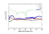
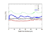
도 4a 내지 4d는 각 실시예 및 비교예에 따라 전리튬화된 음극재에 대하여, 표면에서부터 두께 방향으로 리튬의 분포를 이차이온질량분석(Secondary Ion mass Spectrometry ; SIMS) 장비를 이용하여 관찰한 것이다. 4A to 4D show the distribution of lithium in the thickness direction from the surface with respect to the pre-lithiated anode material according to each Example and Comparative Example using Secondary Ion mass Spectrometry (SIMS) equipment. .
도 4a는 실시예 1이고, 도 4b는 실시예 2이고, 도 4c는 비교예 1이고, 도 4d는 비교예 2이다. 4A is Example 1, FIG. 4B is Example 2, FIG. 4C is Comparative Example 1, and FIG. 4D is Comparative Example 2.
실시예 1 내지 2에서는 표면의 리튬 함량이 음극재 60㎛ 깊이까지 균일하게 유지되고 있음을 보여 준다. 즉, 음극재 롤의 양면에 전해액이 잘 노출된 상태에서 리튬 금속 전극과 음극재 간의 간격을 최적화하여 유지할 경우, 면적 방향 뿐만 아니라 깊이 방향으로 균일한 전류 분포가 형성되는 것을 알 수 있다. In Examples 1 to 2, it is shown that the lithium content on the surface is maintained uniformly to a depth of 60 µm. That is, when the gap between the lithium metal electrode and the negative electrode material is optimized and maintained while the electrolyte is well exposed on both surfaces of the negative electrode material roll, it can be seen that a uniform current distribution is formed not only in the area direction but also in the depth direction.
이로부터 넓은 면적에 걸쳐 균일한 전리튬화가 가능할 뿐만 아니라 음극재 두께 방향에 있어서도 표면에서부터 음극재 기저부까지 균일한 리튬의 삽입이 가능하다는 것을 보여 준다. From this, it is shown that not only uniform pre-lithiation is possible over a large area, but uniform lithium can be inserted from the surface to the base of the negative electrode material in the thickness direction of the negative electrode material.
반면, 직접 접촉시킨 비교예 1에서는 표면과 기저부간의 리튬의 분포가 불균일함을 보여 준다. 표면에서의 리튬 함량은 높게 나타나는 반면, 기저부의 리튬 함량은 크게 저하된다. 이는 도 3의 (c)에 있는 비교예 1의 음극재 표면 외관에 대한 결과와도 일치함을 알 수 있다. On the other hand, Comparative Example 1 in direct contact shows that the distribution of lithium between the surface and the base was non-uniform. While the lithium content on the surface is high, the lithium content at the base is greatly reduced. It can be seen that this is consistent with the results for the surface appearance of the negative electrode material of Comparative Example 1 in FIG. 3 (c).
한편, 비교예 2에서는 동일한 전류가 인가되었음에도 불구하고 전체적으로 삽입된 리튬의 양이 실시예 1, 2 대비 낮게 나타난다. 또한, 40㎛ 이후의 깊이 영역에서는 리튬 함량이 급격히 감소함을 보여 준다. 즉, 비교예 1과 유사하게 표면의 리튬 함량이 기저부까지 균일하게 유지되지 않아, 균일한 전리튬화가 이루어지지 못하고 있음을 보여 준다. On the other hand, in Comparative Example 2, although the same current was applied, the amount of lithium inserted as a whole appears lower than Examples 1 and 2. In addition, it is shown that the lithium content rapidly decreases in the depth region after 40 μm. That is, similar to Comparative Example 1, it is shown that the lithium content of the surface is not maintained uniformly to the base, and thus, uniform pre-lithiation is not achieved.
이와 같은 사실로부터, 비교예 2와 같이 과도한 간격을 유지한 상태로 전리튬화를 실시할 경우, 효율적인 전류의 사용 측면뿐만 아니라 전리튬화의 균일도 측면에서 적절하지 않음을 알 수 있다.From this fact, it can be seen that, in the case of performing pre-lithiation in a state where excessive spacing is maintained as in Comparative Example 2, it is not suitable not only in terms of efficient current use but also in terms of uniformity of pre-lithiation.
도 5는 각 실시예 및 비교예에 따라 전리튬화된 음극재를 이용하여, 코인셀을 제작하고 충방전 특성 평가를 실시한 결과이다. 평가에 사용된 코인셀은 2032형 크기를 가지며, 양극재로는 Li1 +x(NiyMnzCow)1- xO2 계열의 물질을 사용하였다. 5 is a result of conducting an evaluation of charging and discharging characteristics by manufacturing a coin cell using an all-lithiated anode material according to each example and comparative example. The coin cell used in the evaluation has a size of 2032 type, and a material of Li 1 + x (Ni y Mn z Co w ) 1- x O 2 was used as a cathode material.
충전 조건은 정전류-정전압 혼합 모드로 정전류는 0.1C, 정전압은 4.2V 이며, 컷오프 전류는 0.05C로 설정하였다. The charging condition was a constant current-constant voltage mixed mode, the constant current was 0.1C, the constant voltage was 4.2V, and the cutoff current was set to 0.05C.
한편 방전 조건은 정전류 모드로 정전류는 0.1C 이며, 컷오프 전압은 2.5V로 설정하였다. 실시예 1 및 2에서는 높은 충방전 용량을 보여 줌으로써 음극재의 전리튬화에 따른 용량 상승의 효과를 나타낸다. Meanwhile, the discharge condition was a constant current mode, the constant current was 0.1C, and the cutoff voltage was set to 2.5V. In Examples 1 and 2, by showing a high charge and discharge capacity, the effect of the capacity increase according to the pre-lithiation of the negative electrode material is shown.
반면 비교예 1에서는 초기 싸이클 과정에서 불안정한 충방전 성능을 보여 주었으며, 비교예 2에서는 실시예 대비 용량이 현저히 낮아 전리튬화에 따른 용량 상승의 효과가 나타나지 않는다.On the other hand, Comparative Example 1 showed unstable charging and discharging performance in the initial cycle process, and in Comparative Example 2, the capacity was significantly lower than that of the Example, and thus there was no effect of capacity increase due to pre-lithiation.
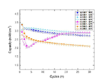
도 6에서는 충방전 성능 평가 시의 충전 및 방전 용량으로부터 계산한 쿨롱 효율(Columb Efficiency)를 나타낸 것이다. 실시예 1 및 2에서는 최초 충방전 과정인 첫번째 cycle에서 92% 수준의 높은 초기쿨롱효율(Initial Columb Efficiency, ICE)를 보여 준다. In FIG. 6, the Coulombic efficiency calculated from the charge and discharge capacities when evaluating charge and discharge performance is shown. Examples 1 and 2 show a high initial columb efficiency (ICE) of 92% level in the first cycle of the initial charge / discharge process.
이는 전리튬화를 통하여 사전에 보상된 리튬의 효과로 초기 비가역 반응에 따른 활성리튬의 감소가 크게 완화되었기 때문이다. 반면, 비교예 1 및 비교예 2에서는 초기쿨롱효율이 86% 및 82% 수준으로 나타났다. This is because the reduction of active lithium due to the initial irreversible reaction was greatly alleviated by the effect of lithium previously compensated through pre-lithiation. On the other hand, in Comparative Examples 1 and 2, the initial coulomb efficiency was found to be 86% and 82%.
전리튬화를 실시하지 않은 규소 산화물계 물질을 음극재로 사용한 경우의 초기쿨롱효율이 약 70% 수준임을 감안하면 비교예에서는 전리튬화의 효과가 충분히 나타나지 않음을 알 수 있다. Considering that the initial coulomb efficiency is about 70% when a silicon oxide-based material that is not pre-lithiated is used as a negative electrode material, it can be seen that the effect of pre-lithiation is not sufficiently exhibited in the comparative example.
따라서, 본 발명의 일 실시예으로부터 음극재, 특히 특히 탄소계 물질 보다 10배 이상의 유효 용량을 가지는 규소계 및 규소산화계 물질이 포함된 음극재를 전리튬화 할 경우, 음극재 전체 면적 영역에서 균일하게 리튬을 보상할 수 있을 뿐만 아니라, 음극재 두께 방향에 대해서도 표면에서부터 집전체에 이르는 기저부까지 균일한 리튬의 삽입이 가능하다. Accordingly, in an embodiment of the present invention, when an anode material, especially a cathode material containing silicon-based and silicon oxide-based materials having an effective capacity of at least 10 times greater than that of a carbon-based material is pre-lithiated, is uniform in the entire area of the anode material Not only can lithium be compensated, it is also possible to uniformly insert lithium from the surface to the base of the current collector in the thickness direction of the negative electrode material.
또한, 전기화학적 방법을 이용하여 전리튬화를 하기 때문에, 인가되는 전류를 제어하면 보상되는 리튬의 양이 정확하게 제어될 수 있다. 이와 같이, 리튬이 전 영역에 대하여 균일하면서도 정량적으로 잘 보상된 전리튬화 음극재로 리튬이차전지를 제작할 경우, 초기 비가역 문제가 해결됨에 따라 높은 초기쿨롱효율 및 높은 전지 에너지밀도를 얻을 수 있을 뿐만 아니라 전지의 안정성 측면에 있어서도 우수한 효과를 기대할 수 있다.In addition, since pre-lithiation is performed using an electrochemical method, the amount of lithium to be compensated can be accurately controlled by controlling the applied current. As described above, when a lithium secondary battery is manufactured with an all-lithiated negative electrode material in which lithium is uniformly and quantitatively well compensated for all regions, as the initial irreversible problem is solved, high initial coulomb efficiency and high battery energy density can be obtained. In addition, excellent effects can be expected in terms of battery stability.
본 발명은 상기 실시예들에 한정되는 것이 아니라 서로 다른 다양한 형태로 제조될 수 있으며, 본 발명이 속하는 기술분야에서 통상의 지식을 가진 자는 본 발명의 기술적 사상이나 필수적인 특징을 변경하지 않고서 다른 구체적인 형태로 실시될 수 있다는 것을 이해할 수 있을 것이다. 그러므로 이상에서 기술한 실시예들은 모든 면에서 예시적인 것이며 한정적이 아닌 것으로 이해해야만 한다.The present invention is not limited to the above embodiments, but may be manufactured in various different forms, and those skilled in the art to which the present invention pertains have other specific forms without changing the technical spirit or essential features of the present invention. It will be understood that can be implemented as. Therefore, it should be understood that the above-described embodiments are illustrative in all respects and not restrictive.
Claims (14)
상기 음극 활물질층은 두께 방향으로 균일하게 전리튬화(pre-lithiation)된 것인 리튬 이차 전지용 음극.
Current collector; And a negative electrode active material layer positioned on the current collector.
The negative electrode active material layer is a lithium secondary battery negative electrode that is uniformly pre-lithiation (pre-lithiation) in the thickness direction.
상기 음극 활물질의 전체 두께 방향에 대해 임의의 지점에서의 리튬의 함량은,
상기 음극 활물질층의 표면부에서부터 두께 방향으로 20길이% 내의 리튬 함량의 최소값 및 최대값의 범위 내의 값인 것인 리튬 이차 전지용 음극.
According to claim 1,
The content of lithium at any point with respect to the overall thickness direction of the negative electrode active material,
The negative electrode for a lithium secondary battery, which is a value within a range of a minimum value and a maximum value of lithium content in 20 length% in the thickness direction from the surface portion of the negative electrode active material layer.
상기 음극 활물질층의 표면은 리튬 도금층이 존재하지 않는 것인 리튬 이차 전지용 음극.
According to claim 1,
A negative electrode for a lithium secondary battery, wherein a surface of the negative electrode active material layer does not have a lithium plating layer.
상기 음극 활물질층 내 음극 활물질은,
규쇼계 화합물, 규소 산화물계 화합물, 탄소계 화합물, 또는 이들의 조합을 포함하는 것인 리튬 이차 전지용 음극.
According to claim 1,
The negative electrode active material in the negative electrode active material layer,
A negative electrode for a lithium secondary battery comprising a silicon-based compound, a silicon oxide-based compound, a carbon-based compound, or a combination thereof.
상기 음극은,
상기 집전체 양면에 상기 음극 활물질층이 위치하는 구조인 것인 리튬 이차 전지용 음극.
According to claim 1,
The cathode,
A negative electrode for a lithium secondary battery having a structure in which the negative electrode active material layer is located on both sides of the current collector.
상기 음극 활물질층의 두께는 10 내지 200㎛인 것인 리튬 이차 전지용 음극.
According to claim 1,
The negative electrode active material layer has a thickness of 10 to 200㎛, the negative electrode for a lithium secondary battery.
상기 음극 활물질층 표면에 위치하는 피막을 더 포함하는 것인 리튬 이차 전지용 음극.
According to claim 1,
A negative electrode for a lithium secondary battery, further comprising a film located on the surface of the negative electrode active material layer.
상기 피막은 Li-N-C-H-O계 이온성 화합물, Li-P-C-H-O계 이온성 화합물, LiF 또는 이들의 조합인 것인 리튬 이차 전지용 음극.
The method of claim 7,
The coating is a negative electrode for a lithium secondary battery, which is a Li-NCHO-based ionic compound, a Li-PCHO-based ionic compound, LiF or a combination thereof.
상기 음극 및 리튬 전극에 전류를 인가하여, 상기 음극을 전리튬화(pre-lithiation)시키는 단계;
를 포함하고,
상기 음극 및 리튬 전극의 간격은, 0 초과 및 1,500㎛ 이하인 것인 리튬 이차 전지용 음극의 제조 방법.
Preparing a negative electrode and a lithium electrode opposed thereto, impregnated in the electrolyte solution; And
Applying a current to the negative electrode and the lithium electrode, thereby pre-lithiating the negative electrode;
Including,
The gap between the negative electrode and the lithium electrode is a method of manufacturing a negative electrode for a lithium secondary battery, which is greater than 0 and less than 1,500 μm.
상기 전류 밀도는 리튬 전극의 면적을 기준으로 0.1 내지 100 mA/cm2인 것인 리튬 이차 전지용 음극의 제조 방법.
The method of claim 9,
The current density is 0.1 to 100 mA / cm 2 based on the area of the lithium electrode.
상기 리튬 전극의 면적은 25 내지 1,000cm2인 것인 리튬 이차 전지용 음극의 제조 방법.
The method of claim 9,
The area of the lithium electrode is 25 to 1,000cm 2 The method of manufacturing a negative electrode for a lithium secondary battery.
상기 음극 및 리튬 전극 사이에 분리막을 위치시키는 것인 리튬 이차 전지용 음극의 제조 방법.
The method of claim 9,
A method of manufacturing a negative electrode for a lithium secondary battery, wherein a separator is positioned between the negative electrode and the lithium electrode.
상기 음극은 제1항에 따른 음극인 것인 리튬 이차 전지.
anode; cathode; And an electrolyte positioned between the positive electrode and the negative electrode,
The negative electrode is a lithium secondary battery that is the negative electrode according to claim 1.
상기 리튬 이차 전지는 초기 쿨롱 효율이 90 내지 110%인 것인 리튬 이차 전지.
The method of claim 13,
The lithium secondary battery is a lithium secondary battery having an initial Coulomb efficiency of 90 to 110%.
Priority Applications (2)
| Application Number | Priority Date | Filing Date | Title |
|---|---|---|---|
| KR1020180136752A KR20200053300A (en) | 2018-11-08 | 2018-11-08 | Negative electrode for lithium secondary battery, method of preparing the saem, and lithium secondary battery using the same |
| PCT/KR2019/010221 WO2020096177A1 (en) | 2018-11-08 | 2019-08-12 | Negative electrode for lithium secondary battery, method for manufacturing same, and lithium secondary battery using same |
Applications Claiming Priority (1)
| Application Number | Priority Date | Filing Date | Title |
|---|---|---|---|
| KR1020180136752A KR20200053300A (en) | 2018-11-08 | 2018-11-08 | Negative electrode for lithium secondary battery, method of preparing the saem, and lithium secondary battery using the same |
Publications (1)
| Publication Number | Publication Date |
|---|---|
| KR20200053300A true KR20200053300A (en) | 2020-05-18 |
Family
ID=70611400
Family Applications (1)
| Application Number | Title | Priority Date | Filing Date |
|---|---|---|---|
| KR1020180136752A KR20200053300A (en) | 2018-11-08 | 2018-11-08 | Negative electrode for lithium secondary battery, method of preparing the saem, and lithium secondary battery using the same |
Country Status (2)
| Country | Link |
|---|---|
| KR (1) | KR20200053300A (en) |
| WO (1) | WO2020096177A1 (en) |
Cited By (4)
| Publication number | Priority date | Publication date | Assignee | Title |
|---|---|---|---|---|
| WO2022039448A1 (en) * | 2020-08-21 | 2022-02-24 | 주식회사 엘지에너지솔루션 | Apparatus for pre-lithiation of negative electrode and method for pre-lithiation of negative electrode |
| KR20220045397A (en) | 2020-10-05 | 2022-04-12 | 주식회사 엘지에너지솔루션 | Apparatus for pre-lithiating the negative electrode and method for pre-lithiating the negative electrode |
| KR20220045396A (en) | 2020-10-05 | 2022-04-12 | 주식회사 엘지에너지솔루션 | Apparatus for pre-lithiating the negative electrode and method for pre-lithiating the negative electrode |
| WO2022085995A1 (en) * | 2020-10-19 | 2022-04-28 | 주식회사 엘지에너지솔루션 | Method for manufacturing anode having inorganic coating layer formed thereon |
Families Citing this family (3)
| Publication number | Priority date | Publication date | Assignee | Title |
|---|---|---|---|---|
| KR20220028269A (en) * | 2020-08-28 | 2022-03-08 | 주식회사 엘지에너지솔루션 | Method for pre-lithiating the negative electrode |
| CN114464778A (en) * | 2022-01-18 | 2022-05-10 | 清华大学 | Method for preparing negative pole piece, negative pole piece and secondary battery |
| CN115050927B (en) * | 2022-06-29 | 2023-09-08 | 齐鲁中科电工先进电磁驱动技术研究院 | Pre-lithiation method and pre-lithiation system |
Family Cites Families (5)
| Publication number | Priority date | Publication date | Assignee | Title |
|---|---|---|---|---|
| JP4918418B2 (en) * | 2007-06-13 | 2012-04-18 | アドバンスト・キャパシタ・テクノロジーズ株式会社 | Lithium ion pre-doping method and method for producing lithium ion capacitor storage element |
| KR101128585B1 (en) * | 2010-07-26 | 2012-03-23 | 삼성전기주식회사 | Pre-doping System of electrode and pre-doping method of electrode using the same |
| JP6294348B2 (en) * | 2013-03-11 | 2018-03-14 | エルジー・ケム・リミテッド | Lithium pre-doping method, method for producing lithium secondary battery including this method, and lithium secondary battery produced by this method |
| KR101820463B1 (en) * | 2013-07-30 | 2018-01-19 | 주식회사 엘지화학 | Pre-lithiation Method of Anode Electrodes |
| KR20180054589A (en) * | 2015-10-05 | 2018-05-24 | 세키스이가가쿠 고교가부시키가이샤 | Lithium ion secondary battery |
-
2018
- 2018-11-08 KR KR1020180136752A patent/KR20200053300A/en not_active IP Right Cessation
-
2019
- 2019-08-12 WO PCT/KR2019/010221 patent/WO2020096177A1/en active Application Filing
Cited By (6)
| Publication number | Priority date | Publication date | Assignee | Title |
|---|---|---|---|---|
| WO2022039448A1 (en) * | 2020-08-21 | 2022-02-24 | 주식회사 엘지에너지솔루션 | Apparatus for pre-lithiation of negative electrode and method for pre-lithiation of negative electrode |
| KR20220045397A (en) | 2020-10-05 | 2022-04-12 | 주식회사 엘지에너지솔루션 | Apparatus for pre-lithiating the negative electrode and method for pre-lithiating the negative electrode |
| KR20220045396A (en) | 2020-10-05 | 2022-04-12 | 주식회사 엘지에너지솔루션 | Apparatus for pre-lithiating the negative electrode and method for pre-lithiating the negative electrode |
| WO2022075602A1 (en) * | 2020-10-05 | 2022-04-14 | 주식회사 엘지에너지솔루션 | Apparatus for pre-lithiation of anode and method for pre-lithiation of anode |
| CN114788047A (en) * | 2020-10-05 | 2022-07-22 | 株式会社Lg新能源 | Apparatus for prelithiating an anode and method for prelithiating an anode |
| WO2022085995A1 (en) * | 2020-10-19 | 2022-04-28 | 주식회사 엘지에너지솔루션 | Method for manufacturing anode having inorganic coating layer formed thereon |
Also Published As
| Publication number | Publication date |
|---|---|
| WO2020096177A1 (en) | 2020-05-14 |
Similar Documents
| Publication | Publication Date | Title |
|---|---|---|
| KR20200053300A (en) | Negative electrode for lithium secondary battery, method of preparing the saem, and lithium secondary battery using the same | |
| KR102603481B1 (en) | High salt concentration electrolyte for rechargeable lithium batteries | |
| CN110291666B (en) | Lithium metal negative electrode, method of preparing the same, and lithium secondary battery comprising the same | |
| WO2015020074A1 (en) | Non-aqueous electrolyte, and electrochemical device provided with said electrolyte | |
| CN107408670B (en) | Electrode for electrochemical device, method of preparing the same, and electrochemical device comprising the same | |
| EP4287295A1 (en) | Secondary battery charging method and charging system | |
| EP3879602A1 (en) | Lithium metal anode, method for manufacturing same, and lithium secondary battery using same | |
| KR102560652B1 (en) | Negative electrode for lithium secondary battery, method of preparing the saem, and lithium secondary battery using the same | |
| US20220376236A1 (en) | Negative electrode for lithium secondary battery, manufacturing thereof, and lithium secondary battery using same | |
| US20230088842A1 (en) | Composite anode for lithium secondary battery and method of manufacturing the same | |
| WO2018098249A2 (en) | Stable low voltage electrochemical cell | |
| US20230378792A1 (en) | Secondary battery charging method and charging system | |
| KR20190025529A (en) | A method for manufacturing an electrochemical device | |
| EP3444873B1 (en) | Anode for lithium metal secondary battery and lithium metal secondary battery comprising same | |
| EP4203095A1 (en) | Anode for lithium secondary battery, manufacturing method therefor, and lithium secondary battery comprising same | |
| JP2005085570A (en) | Thin film electrode, its manufacturing method, lithium secondary battery using it | |
| KR20230035736A (en) | Lithium secondary battery comprising lithium metal anode having protective layer and producing method thereof | |
| KR20220163581A (en) | Lithium Metal Thin Film Composite and Method for Preparing the Same | |
| EP4273991A1 (en) | Lithium secondary battery | |
| KR20230138935A (en) | High capacity and high reversible anode for lithium secondary batteries, manufacturing method for the same, and lithium secondary batteries including the same | |
| CN115863769A (en) | Fluorinated carbonate electrolyte and lithium metal battery | |
| CN114361585A (en) | Electrolyte for lithium secondary battery and lithium secondary battery including the same | |
| CN115642317A (en) | Lithium ion battery, lithium supplement electrode and preparation method thereof | |
| CN115053365A (en) | Method for manufacturing negative electrode |
Legal Events
| Date | Code | Title | Description |
|---|---|---|---|
| AMND | Amendment | ||
| E601 | Decision to refuse application | ||
| X091 | Application refused [patent] | ||
| AMND | Amendment | ||
| X601 | Decision of rejection after re-examination |