KR20200052676A - Battery Module - Google Patents
Battery Module Download PDFInfo
- Publication number
- KR20200052676A KR20200052676A KR1020180135949A KR20180135949A KR20200052676A KR 20200052676 A KR20200052676 A KR 20200052676A KR 1020180135949 A KR1020180135949 A KR 1020180135949A KR 20180135949 A KR20180135949 A KR 20180135949A KR 20200052676 A KR20200052676 A KR 20200052676A
- Authority
- KR
- South Korea
- Prior art keywords
- battery
- case
- battery stack
- stacking direction
- sidewall
- Prior art date
Links
- 238000000034 method Methods 0.000 claims description 21
- 238000003780 insertion Methods 0.000 claims description 12
- 230000037431 insertion Effects 0.000 claims description 12
- 230000008878 coupling Effects 0.000 claims description 8
- 238000010168 coupling process Methods 0.000 claims description 8
- 238000005859 coupling reaction Methods 0.000 claims description 8
- 238000003466 welding Methods 0.000 abstract description 18
- 238000004519 manufacturing process Methods 0.000 abstract description 6
- 238000003908 quality control method Methods 0.000 abstract description 5
- 210000004027 cell Anatomy 0.000 description 40
- 210000005056 cell body Anatomy 0.000 description 7
- 230000007547 defect Effects 0.000 description 6
- WHXSMMKQMYFTQS-UHFFFAOYSA-N Lithium Chemical compound [Li] WHXSMMKQMYFTQS-UHFFFAOYSA-N 0.000 description 2
- 238000005452 bending Methods 0.000 description 2
- OJIJEKBXJYRIBZ-UHFFFAOYSA-N cadmium nickel Chemical compound [Ni].[Cd] OJIJEKBXJYRIBZ-UHFFFAOYSA-N 0.000 description 2
- 229910052744 lithium Inorganic materials 0.000 description 2
- 229910052987 metal hydride Inorganic materials 0.000 description 2
- 230000008961 swelling Effects 0.000 description 2
- 230000000903 blocking effect Effects 0.000 description 1
- 238000005520 cutting process Methods 0.000 description 1
- 230000000694 effects Effects 0.000 description 1
- 238000005516 engineering process Methods 0.000 description 1
- 229910052739 hydrogen Inorganic materials 0.000 description 1
- 239000001257 hydrogen Substances 0.000 description 1
- 239000011810 insulating material Substances 0.000 description 1
- 238000005304 joining Methods 0.000 description 1
- 210000004185 liver Anatomy 0.000 description 1
- 239000000463 material Substances 0.000 description 1
- 238000012986 modification Methods 0.000 description 1
- 230000004048 modification Effects 0.000 description 1
- 238000007789 sealing Methods 0.000 description 1
Images

Classifications
-
- H01M2/1077—
-
- H—ELECTRICITY
- H01—ELECTRIC ELEMENTS
- H01M—PROCESSES OR MEANS, e.g. BATTERIES, FOR THE DIRECT CONVERSION OF CHEMICAL ENERGY INTO ELECTRICAL ENERGY
- H01M50/00—Constructional details or processes of manufacture of the non-active parts of electrochemical cells other than fuel cells, e.g. hybrid cells
- H01M50/50—Current conducting connections for cells or batteries
- H01M50/502—Interconnectors for connecting terminals of adjacent batteries; Interconnectors for connecting cells outside a battery casing
- H01M50/514—Methods for interconnecting adjacent batteries or cells
- H01M50/516—Methods for interconnecting adjacent batteries or cells by welding, soldering or brazing
-
- H—ELECTRICITY
- H01—ELECTRIC ELEMENTS
- H01M—PROCESSES OR MEANS, e.g. BATTERIES, FOR THE DIRECT CONVERSION OF CHEMICAL ENERGY INTO ELECTRICAL ENERGY
- H01M50/00—Constructional details or processes of manufacture of the non-active parts of electrochemical cells other than fuel cells, e.g. hybrid cells
- H01M50/20—Mountings; Secondary casings or frames; Racks, modules or packs; Suspension devices; Shock absorbers; Transport or carrying devices; Holders
-
- H01M2/1061—
-
- H01M2/204—
-
- H01M2/206—
-
- H01M2/26—
-
- H01M2/30—
-
- H—ELECTRICITY
- H01—ELECTRIC ELEMENTS
- H01M—PROCESSES OR MEANS, e.g. BATTERIES, FOR THE DIRECT CONVERSION OF CHEMICAL ENERGY INTO ELECTRICAL ENERGY
- H01M50/00—Constructional details or processes of manufacture of the non-active parts of electrochemical cells other than fuel cells, e.g. hybrid cells
- H01M50/20—Mountings; Secondary casings or frames; Racks, modules or packs; Suspension devices; Shock absorbers; Transport or carrying devices; Holders
- H01M50/204—Racks, modules or packs for multiple batteries or multiple cells
- H01M50/207—Racks, modules or packs for multiple batteries or multiple cells characterised by their shape
- H01M50/209—Racks, modules or packs for multiple batteries or multiple cells characterised by their shape adapted for prismatic or rectangular cells
-
- H—ELECTRICITY
- H01—ELECTRIC ELEMENTS
- H01M—PROCESSES OR MEANS, e.g. BATTERIES, FOR THE DIRECT CONVERSION OF CHEMICAL ENERGY INTO ELECTRICAL ENERGY
- H01M50/00—Constructional details or processes of manufacture of the non-active parts of electrochemical cells other than fuel cells, e.g. hybrid cells
- H01M50/20—Mountings; Secondary casings or frames; Racks, modules or packs; Suspension devices; Shock absorbers; Transport or carrying devices; Holders
- H01M50/262—Mountings; Secondary casings or frames; Racks, modules or packs; Suspension devices; Shock absorbers; Transport or carrying devices; Holders with fastening means, e.g. locks
-
- H—ELECTRICITY
- H01—ELECTRIC ELEMENTS
- H01M—PROCESSES OR MEANS, e.g. BATTERIES, FOR THE DIRECT CONVERSION OF CHEMICAL ENERGY INTO ELECTRICAL ENERGY
- H01M50/00—Constructional details or processes of manufacture of the non-active parts of electrochemical cells other than fuel cells, e.g. hybrid cells
- H01M50/50—Current conducting connections for cells or batteries
- H01M50/502—Interconnectors for connecting terminals of adjacent batteries; Interconnectors for connecting cells outside a battery casing
- H01M50/507—Interconnectors for connecting terminals of adjacent batteries; Interconnectors for connecting cells outside a battery casing comprising an arrangement of two or more busbars within a container structure, e.g. busbar modules
-
- H—ELECTRICITY
- H01—ELECTRIC ELEMENTS
- H01M—PROCESSES OR MEANS, e.g. BATTERIES, FOR THE DIRECT CONVERSION OF CHEMICAL ENERGY INTO ELECTRICAL ENERGY
- H01M50/00—Constructional details or processes of manufacture of the non-active parts of electrochemical cells other than fuel cells, e.g. hybrid cells
- H01M50/50—Current conducting connections for cells or batteries
- H01M50/531—Electrode connections inside a battery casing
-
- H—ELECTRICITY
- H01—ELECTRIC ELEMENTS
- H01M—PROCESSES OR MEANS, e.g. BATTERIES, FOR THE DIRECT CONVERSION OF CHEMICAL ENERGY INTO ELECTRICAL ENERGY
- H01M50/00—Constructional details or processes of manufacture of the non-active parts of electrochemical cells other than fuel cells, e.g. hybrid cells
- H01M50/50—Current conducting connections for cells or batteries
- H01M50/543—Terminals
-
- Y—GENERAL TAGGING OF NEW TECHNOLOGICAL DEVELOPMENTS; GENERAL TAGGING OF CROSS-SECTIONAL TECHNOLOGIES SPANNING OVER SEVERAL SECTIONS OF THE IPC; TECHNICAL SUBJECTS COVERED BY FORMER USPC CROSS-REFERENCE ART COLLECTIONS [XRACs] AND DIGESTS
- Y02—TECHNOLOGIES OR APPLICATIONS FOR MITIGATION OR ADAPTATION AGAINST CLIMATE CHANGE
- Y02E—REDUCTION OF GREENHOUSE GAS [GHG] EMISSIONS, RELATED TO ENERGY GENERATION, TRANSMISSION OR DISTRIBUTION
- Y02E60/00—Enabling technologies; Technologies with a potential or indirect contribution to GHG emissions mitigation
- Y02E60/10—Energy storage using batteries
Abstract
Description
본 발명의 일 실시예는 배터리 모듈에 관한 것이다.One embodiment of the present invention relates to a battery module.
충전 및 방전이 가능한 이차 전지는 디지털 카메라, 셀룰라 폰, 노트북, 하이브리드 자동차 등 첨단 분야의 개발로 활발한 연구가 진행중이다. 이차 전지로는 니켈-카드뮴 전지, 니켈-메탈 하이드라이드 전지, 니켈-수소 전지, 리튬 이차 전지를 들 수 있다. 이중에서, 리튬 이차 전지는 작동 전압이 3.6V 이상으로 휴대용 전자기기의 전원으로 사용되거나, 또는 다수 개를 직렬 연결하여 고출력의 하이브리드 자동차에 사용되는데, 니켈-카드뮴 배터리나, 니켈-메탈 하이드라이드 배터리에 비하여 작동 전압이 3배가 높고, 단위 중량당 에너지 밀도의 특성도 우수하여 급속도로 사용되고 있는 추세이다.Secondary batteries that can be charged and discharged are being actively researched through the development of high-tech fields such as digital cameras, cell phones, notebooks, and hybrid vehicles. Examples of the secondary battery include a nickel-cadmium battery, a nickel-metal hydride battery, a nickel-hydrogen battery, and a lithium secondary battery. Among them, lithium secondary batteries have a working voltage of 3.6 V or higher and are used as power sources for portable electronic devices, or are used in high-power hybrid vehicles by connecting multiple series in series, such as nickel-cadmium batteries or nickel-metal hydride batteries. Compared to this, the operating voltage is three times higher, and the energy density per unit weight is also excellent.
위와 같이, 상기 이차 전지 다수 개를 직렬 연결하여 고출력의 하이브리드 자동차나 전기자동차에 사용하는 경우, 커버 또는 케이스 등의 부재를 이용하여 복수 개의 이차 전지를 고정하고, 이를 버스바 등의 연결부재를 이용하여 복수 개의 이차 전지 상호 간을 전기적으로 연결함으로써 하나의 배터리 모듈 형태로 이용할 수 있다.As described above, when a plurality of secondary batteries are connected in series and used in a high-power hybrid vehicle or an electric vehicle, a plurality of secondary batteries are fixed using a member such as a cover or a case, and a connecting member such as a bus bar is used. Thus, a plurality of secondary batteries can be electrically connected to each other to be used as a single battery module.
이 때, 배터리 모듈의 체적에 대한 에너지 밀도를 향상시키기 위해 공간활용률을 극대화 하는 것이 배터리 모듈 개발의 주된 관심사였고, 종래의 경우 모듈 하우징 내에 이차 전지 복수 개를 세로 방향으로 적층하여 수납하는 방식이 주로 이용되었다. 하지만, 이 경우 모듈 하우징을 형성하기 위해 복수 개의 외관 케이스 부재를 필요로 하였으며, 여러 개의 케이스 부재 상호 간을 연결하기 위해 용접 공정이 주로 이용되었다.At this time, maximizing the space utilization rate in order to improve the energy density with respect to the volume of the battery module was the main concern of the battery module development, and in the conventional case, the method of storing a plurality of secondary batteries stacked vertically in the module housing is mainly used. Was used. However, in this case, a plurality of exterior case members were required to form the module housing, and a welding process was mainly used to connect the plurality of case members to each other.
하지만, 종래의 배터리 모듈의 경우, 상술한 용접 등의 제조 과정 간 공정상의 제조 비용 및 용접 품질관리에 대한 부담이 증가될 수 밖에 없었고, 용접 등의 접합 상태에 따라 배터리 모듈 제품 간 품질 수준 편차가 발생할 수 밖에 없는 문제가 존재하였다.However, in the case of the conventional battery module, the manufacturing cost in the process between the above-described manufacturing processes such as welding and the burden on welding quality control were inevitably increased. There were problems that had to arise.
본 발명의 실시예들은 외관 케이스의 부품 수를 최소화 하여 종래 6면의 외관 케이스 결합 간 용접 등의 제조 비용 및 품질관리의 부담을 경감시킬 수 있는 배터리 모듈을 제공하기 위한 것이다.Embodiments of the present invention is to provide a battery module that can reduce the burden of manufacturing cost and quality control, such as welding between the conventional six-sided outer case coupling by minimizing the number of parts of the outer case.
또한, 본 발명의 실시예들은 비용접 체결 구조를 통해 종래의 외관 케이스 결합을 위한 용접 과정에서 발생하였던 용접 불량 등의 공정상 품질 불량 발생을 차단할 수 있는 배터리 모듈을 제공하기 위한 것이다.In addition, embodiments of the present invention is to provide a battery module capable of blocking the occurrence of process quality defects such as welding defects that occurred in a welding process for bonding a conventional exterior case through a non-welding fastening structure.
또한, 본 발명의 실시예들은 외관 케이스의 부품 수가 감소되고 가스켓이 배치 됨에 따라 방수/방진 성능이 향상될 수 있는 배터리 모듈을 제공하기 위한 것이다.In addition, embodiments of the present invention is to provide a battery module that can improve the waterproof / dustproof performance as the number of parts of the outer case is reduced and the gasket is disposed.
또한, 본 발명의 실시예들은 복수 개 체결부재의 교차 체결을 통해 구조적 강성이 향상될 수 있는 배터리 모듈을 제공하기 위한 것이다.In addition, embodiments of the present invention is to provide a battery module capable of improving structural rigidity through cross-fastening of a plurality of fastening members.
또한, 본 발명의 실시예들은 복수 개의 배터리 셀의 적층 방향 측벽 중첩 구조를 통해 구조적 강성이 향상되어 배터리 셀이 부푸는 것을 효과적으로 억제할 수 있는 배터리 모듈을 제공하기 위한 것이다.In addition, embodiments of the present invention is to provide a battery module that can effectively suppress the swelling of the battery cell by improving the structural stiffness through the stacking direction side wall overlap structure of a plurality of battery cells.
또한, 본 발명의 실시예들은 이중의 측벽 구조를 통해 종래의 배터리 셀 사이에 배치되었던 완충부재를 제거할 수 있고, 외관 케이스의 내부 공간 효율이 향상될 수 있는 배터리 모듈을 제공하기 위한 것이다.In addition, embodiments of the present invention is to provide a battery module capable of removing the buffer member disposed between the conventional battery cells through the double sidewall structure, and improving the internal space efficiency of the exterior case.
본 발명의 일 실시예에 따르면, 각각이 전극 탭을 포함하는 복수 개의 배터리 셀이 상호 적층되어 형성된 배터리 적층체; 상기 배터리 적층체의 일측면을 감싸는 하면부와 상기 배터리 적층체의 상기 배터리 셀 적층 방향 양측에 위치된 한 쌍의 제1 측벽부를 포함하는 제1 케이스부; 및 상기 배터리 적층체의 타측면을 감싸는 상면부와 상기 배터리 적층체의 상기 배터리 셀 적층 방향 양측에 위치된 한 쌍의 제2 측벽부를 포함하는 제2 케이스부;를 포함하고, 상기 제1 측벽부 및 상기 제2 측벽부는 적어도 일부가 상호 중첩된 상태로 상기 배터리 적층체의 상기 배터리 셀 적층 방향 양측에 위치된, 배터리 모듈을 제공할 수 있다.According to an embodiment of the present invention, a battery stack formed by stacking a plurality of battery cells, each of which includes an electrode tab; A first case portion including a lower surface portion surrounding one side surface of the battery stack body and a pair of first side wall portions located on both sides of the battery cell stacking direction in the battery stack body; And a second case part including an upper surface part surrounding the other side of the battery stack and a pair of second side wall parts located on both sides of the battery cell stacking direction of the battery stack. And at least a portion of the second sidewall portion overlapped with each other, and located on both sides of the battery cell stacking direction of the battery stack.
상기 제1 케이스부 및 상기 제2 케이스부는 상기 배터리 적층체를 사이에 두고 체결되어 내부에 상기 배터리 적층체를 수용하는 하우징부를 형성할 수 있다.The first case part and the second case part may be fastened with the battery stack interposed therebetween to form a housing part accommodating the battery stack therein.
한 쌍의 상기 제1 측벽부 각각은 상기 하면부의 상기 적층 방향 단부에서 상기 하면부에 수직하게 연장 형성되고, 상기 제1 측벽부는 상기 하면부의 상기 적층 방향 말단에서 소정 거리 내측에 위치되며, 상기 하면부의 상기 적층 방향 말단에는 상기 제1 측벽부의 외측으로 돌출된 안착부가 형성될 수 있다.Each of the pair of first sidewall portions is formed to extend perpendicularly to the bottom portion at the stacking direction end of the bottom portion, and the first sidewall portion is located inside a predetermined distance from the stacking direction end of the bottom portion, and the bottom surface A seating portion protruding outward from the first sidewall portion may be formed at the end of the stacking direction of the portion.
한 쌍의 상기 제2 측벽부 각각은 상기 상면부의 상기 적층 방향 단부에서 상기 상면부에 수직하게 연장 형성되며, 상기 제2 측벽부의 상기 연장 방향 말단은 상기 안착부에 안착될 수 있다.Each of the pair of second sidewall portions may be formed to extend perpendicular to the top surface portion at the stacking direction end of the top surface portion, and the extension direction end of the second sidewall portion may be seated on the seating portion.
상기 제1 측벽부 및 상기 제2 측벽부 중 어느 하나는 상기 배터리 적층체의 상기 적층 방향 외면을 감싸며 면상 접촉될 수 있다.Any one of the first sidewall portion and the second sidewall portion may enclose the outer surface of the battery stack in the stacking direction and be in plan contact.
상기 제1 측벽부 및 상기 제2 측벽부 각각은 상기 배터리 셀의 상기 적층 방향에 수직한 평면 면적에 대응되는 면적으로 형성될 수 있다.Each of the first sidewall portion and the second sidewall portion may be formed with an area corresponding to a plane area perpendicular to the stacking direction of the battery cell.
상기 제1 케이스부 및 상기 제2 케이스부 상호 간은 비용접의 기계식 체결에 의해 결합될 수 있다.The first case portion and the second case portion may be coupled to each other by mechanical fastening of a non-welding.
상기 제1 케이스부 및 상기 제2 케이스부 각각은 상기 배터리 적층체의 상기 전극 탭이 인출되는 방향 양측면 적어도 일부를 감싸는 제1 전후면부 및 제2 전후면부 각각을 포함하고, 상기 제1 케이스부 및 상기 제2 케이스부의 상호 결합을 위한 제1 체결구는 상기 배터리 적층체의 상기 전극 탭이 인출되는 방향에서 제1 체결부재를 삽입 가능한 구조로 형성될 수 있다.Each of the first case portion and the second case portion includes a first front and rear surface portion and a second front and rear surface portion surrounding at least a portion of both sides of a direction in which the electrode tab of the battery stack is pulled out, and the first case portion and The first fastener for mutual coupling of the second case part may be formed in a structure capable of inserting a first fastening member in a direction in which the electrode tab of the battery stack is pulled out.
상기 제1 케이스부 및 상기 제2 케이스부의 상호 결합을 위한 제2 체결구는 상기 배터리 적층체의 상기 적층 방향에서 제2 체결부재를 삽입 가능한 구조로 형성될 수 있다.The first case portion and the second fastener for mutual coupling of the second case portion may be formed in a structure capable of inserting a second fastening member in the stacking direction of the battery stack.
상기 배터리 적층체 및 상기 상면부 사이에서 상기 상면부의 테두리를 따라 배치된 가스켓(gasket)을 더 포함할 수 있다.Between the battery stack and the upper surface portion may further include a gasket (gasket) disposed along the edge of the upper surface portion.
상기 전극 탭 상호 간을 전기적으로 연결하는 적어도 하나의 버스바; 및 상기 적어도 하나의 버스바를 고정 및 지지하는 버스바 지지체;를 포함하는 버스바 조립체를 더 포함할 수 있다.At least one bus bar electrically connecting the electrode tabs to each other; And a bus bar support for fixing and supporting the at least one bus bar.
상기 버스바 조립체의 및 상기 하면부 중 어느 하나의 일측에는 나머지 하나 측으로 돌출된 적어도 하나의 삽입 가이드가 형성되고, 상기 나머지 하나의 일측에는 내측으로 만입되어 상기 적어도 하나의 삽입 가이드가 삽입 가능한 적어도 하나의 가이드 홈이 형성될 수 있다.At least one insertion guide protruding toward the other side is formed on one side of the bus bar assembly and one of the lower surface portions, and at least one insertion guide is inserted into the other one side to be inserted inward. The guide groove of can be formed.
한편, 본 발명의 다른 실시예에 따르면, 각각이 전극 탭을 포함하는 복수 개의 배터리 셀이 상호 적층되어 형성된 배터리 적층체; 상기 배터리 적층체의 외측면 중 일부를 둘러싸는 제1 케이스부; 및 상기 배터리 적층체의 외측면 중 나머지 일부를 둘러싸는 제2 케이스부;를 포함하고, 상기 제1 케이스부 및 상기 제2 케이스부가 상호 결합됨에 따라 상기 배터리 적층체의 상기 배터리 셀이 적층되는 방향 양측에는 이중의 측벽 구조가 형성된, 배터리 모듈을 제공할 수 있다. On the other hand, according to another embodiment of the present invention, a battery stack formed by stacking a plurality of battery cells, each of which includes an electrode tab to each other; A first case part surrounding a part of the outer surface of the battery stack; And a second case part surrounding the remaining part of the outer surface of the battery stack, wherein the battery cells of the battery stack are stacked as the first case part and the second case part are mutually coupled. A battery module having a double sidewall structure formed on both sides may be provided.
본 발명의 실시예들에 의하면, 외관 케이스의 부품 수를 최소화 하여 종래 6면의 외관 케이스 결합 간 용접 등의 제조 비용 및 품질관리의 부담을 경감시킬 수 있다.According to the embodiments of the present invention, it is possible to minimize the number of parts of the outer case and reduce the burden of manufacturing cost and quality control, such as welding between the outer six outer case combination.
또한, 본 발명의 실시예들에 의하면, 비용접 체결 구조를 통해 종래의 외관 케이스 결합을 위한 용접 과정에서 발생하였던 용접 불량 등의 공정상 품질 불량 발생을 차단할 수 있다.In addition, according to embodiments of the present invention, it is possible to block the occurrence of quality defects in the process, such as welding defects that occurred during the welding process for the conventional outer case coupling through the non-welding fastening structure.
또한, 본 발명의 실시예들에 의하면, 외관 케이스의 부품 수가 감소되고 가스켓이 배치 됨에 따라 방수/방진 성능이 향상될 수 있다.In addition, according to embodiments of the present invention, as the number of parts of the exterior case is reduced and the gasket is disposed, waterproof / dustproof performance may be improved.
또한, 본 발명의 실시예들은 복수 개 체결부재의 교차 체결을 통해 구조적 강성이 향상될 수 있다.In addition, embodiments of the present invention can improve structural rigidity through cross-fastening of a plurality of fastening members.
또한, 본 발명의 실시예들에 의하면, 복수 개의 배터리 셀의 적층 방향 측벽 중첩 구조를 통해 구조적 강성이 향상되어 배터리 셀이 부푸는 것을 효과적으로 억제할 수 있다.In addition, according to embodiments of the present invention, structural stiffness is improved through stacking of sidewalls in a stacking direction of a plurality of battery cells, thereby effectively suppressing battery cells from swelling.
또한, 본 발명의 실시예들에 의하면, 이중의 측벽 구조를 통해 종래의 배터리 셀 사이에 배치되었던 완충부재를 제거할 수 있고, 외관 케이스의 내부 공간 효율이 향상될 수 있다.In addition, according to embodiments of the present invention, the buffer member disposed between the conventional battery cells can be removed through the double sidewall structure, and the internal space efficiency of the exterior case can be improved.
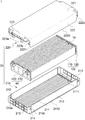
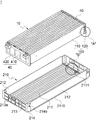
도 1은 본 발명의 일 실시예에 따른 배터리 모듈의 분해 사시도
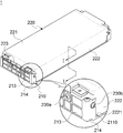
도 2는 본 발명의 일 실시예에 따른 배터리 모듈의 제1 케이스부 및 제2 케이스부 상호 간이 체결되는 모습을 나타낸 도면
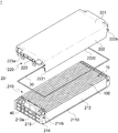
도 3은 본 발명의 일 실시예에 따른 배터리 모듈을 나타낸 도면
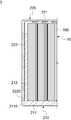
도 4는 도 3에 도시된 본 발명의 일 실시예에 따른 배터리 모듈의 I-I 단면을 나타낸 도면
도 5는 본 발명의 일 실시예에 따른 배터리 모듈의 가스켓이 장착되는 모습을 나타낸 도면
도 6은 본 발명의 일 실시예에 따른 배터리 모듈의 제1 케이스부에 배터리 적층체가 안착되는 모습을 나타낸 도면
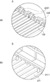
도 7의 (a)는 도 6의 A부분 배면을 하측에서 바라본 부분 확대도이며, 도 7의 (b)는 도 6의 B부분에 대한 부분 확대도1 is an exploded perspective view of a battery module according to an embodiment of the present invention
2 is a view showing a state in which the first case portion and the second case portion of the battery module according to an embodiment of the present invention are mutually fastened
3 is a view showing a battery module according to an embodiment of the present invention
4 is a view showing a cross-section II of the battery module according to an embodiment of the present invention shown in FIG.
5 is a view showing a state in which the gasket of the battery module is mounted according to an embodiment of the present invention
6 is a view showing a state in which the battery stack is seated on the first case portion of the battery module according to an embodiment of the present invention
FIG. 7 (a) is a partial enlarged view of the rear portion A of FIG. 6 when viewed from the bottom, and FIG. 7 (b) is a partial enlarged view of portion B of FIG.
이하, 도면을 참조하여 본 발명의 구체적인 실시형태를 설명하기로 한다. 그러나 이는 예시에 불과하며 본 발명은 이에 제한되지 않는다.Hereinafter, specific embodiments of the present invention will be described with reference to the drawings. However, this is only an example and the present invention is not limited thereto.
본 발명을 설명함에 있어서, 본 발명과 관련된 공지기술에 대한 구체적인 설명이 본 발명의 요지를 불필요하게 흐릴 수 있다고 판단되는 경우에는 그 상세한 설명을 생략하기로 한다. 그리고, 후술되는 용어들은 본 발명에서의 기능을 고려하여 정의된 용어들로서 이는 사용자, 운용자의 의도 또는 관례 등에 따라 달라질 수 있다. 그러므로 그 정의는 본 명세서 전반에 걸친 내용을 토대로 내려져야 할 것이다. In describing the present invention, when it is determined that the detailed description of the known technology related to the present invention may unnecessarily obscure the subject matter of the present invention, the detailed description will be omitted. In addition, terms to be described later are terms defined in consideration of functions in the present invention, which may vary according to a user's or operator's intention or practice. Therefore, the definition should be made based on the contents throughout this specification.
본 발명의 기술적 사상은 청구범위에 의해 결정되며, 이하의 실시예는 본 발명의 기술적 사상을 본 발명이 속하는 기술분야에서 통상의 지식을 가진 자에게 효율적으로 설명하기 위한 일 수단일 뿐이다.The technical spirit of the present invention is determined by the claims, and the following examples are merely a means for effectively explaining the technical spirit of the present invention to a person having ordinary knowledge in the technical field to which the present invention pertains.
도 1은 본 발명의 일 실시예에 따른 배터리 모듈(1)의 분해 사시도이고, 도 2는 본 발명의 일 실시예에 따른 배터리 모듈(1)의 제1 케이스부(210) 및 제2 케이스부(220) 상호 간이 체결되는 모습을 나타낸 도면이며, 도 3은 본 발명의 일 실시예에 따른 배터리 모듈(1)을 나타낸 도면이다.1 is an exploded perspective view of a
도 1 내지 3을 참조하면, 본 발명의 일 실시예에 따른 배터리 모듈(1)은 각각이 전극 탭(120)을 포함하는 복수 개의 배터리 셀(100)이 상호 적층되어 형성된 배터리 적층체(10), 배터리 적층체(10)의 외면 적어도 일부를 감싸는 제1 케이스부(210) 및 상술한 제1 케이스부(210)와 상호 체결 가능하게 구비되어 배터리 적층체(10)의 외면 나머지를 감싸는 제2 케이스부(220)를 포함할 수 있다.1 to 3, the
이 때, 상술한 제1 케이스부(210)는 배터리 적층체(10)의 일측면(도면상 하측면)을 감싸는 하면부(211)와 배터리 적층체(10)의 배터리 셀(100) 적층 방향 양측에 위치된 한 쌍의 제1 측벽부(212)를 포함할 수 있고, 제2 케이스부(220)는 배터리 적층체(10)의 타측면(도면상 상측면)을 감싸는 상면부(221)와 배터리 적층체(10)의 배터리 셀(100) 적층 방향 양측에 위치된 한 쌍의 제2 측벽부(222)를 포함할 수 있다. 상술한 제1 측벽부(212) 및 제2 측벽부(222)는 적어도 일부가 상호 중첩된 상태로 위치될 수 있고, 제1 측벽부(212) 및 제2 측벽부(222)는 상호 중첩된 상태에서 상술한 배터리 적층체(10)의 적층 방향 양측면을 감쌀 수 있다.At this time, the above-described
구체적으로, 상술한 한 쌍의 제1 측벽부(212) 각각은 하면부(211)의 적층 방향 단부에서 하면부(211)에 수직하게 연장 형성될 수 있고, 바람직하게는 하면부(211)의 적층 방향 말단으로부터 내측으로 소정 거리 이격되어 형성될 수 있다. 이를 통해, 전극 탭(120)이 인출되는 방향에서 보았을 때, 하면부(211)의 적층 방향 말단에는 제1 측벽부(212)의 외측으로 돌출된 안착부(2110)가 형성될 수 있고, 안착부(2110)는 상술한 소정 거리만큼 돌출 형성될 수 있다.Specifically, each of the pair of
또한, 상술한 한 쌍의 제2 측벽부(222) 각각은 상면부(221)의 적층 방향 단부에서 상면부(221)에 수직하게 연장 형성될 수 있고, 바람직하게는 상술한 제1 측벽부(212)를 감싸도록 상면부(221)의 적층 방향 단부에서 하향 절곡될 수 있다. 이 때, 제2 측벽부(222)는 상술한 제1 케이스부(210)의 안착부(2110)까지 연장 형성될 수 있고, 제2 측벽부(222)의 연장 방향(상면부(221)에 수직한 하향 절곡 방향) 말단(2220)은 안착부(2110)에 안착 지지될 수 있다.In addition, each of the pair of second
한편, 본 발명의 일 실시예에 따른 배터리 모듈(1)의 배터리 셀(100)은 외장재(미도시 됨)에 의해 감싸진 전극 조립체(미도시 됨) 부분인 셀 바디(110)와 셀 바디(110)로부터 인출된 전극 탭(120)을 포함할 수 있고, 이 때, 배터리 셀(100)의 전극 탭(120)을 제외한 나머지 부분을 셀 바디(110)로 볼 수 있다.Meanwhile, the
나아가, 상술한 제1 측벽부(212) 및 제2 측벽부(222) 각각은 배터리 셀(100)의 적층 방향에 수직한 평면 면적에 대응되는 면적으로 형성될 수 있고, 이를 통해 상호 중첩된 제1 측벽부(212) 및 제2 측벽부(222)는 배터리 적층체(10)의 적층 방향 외측면 전체를 감싸도록 위치될 수 있다. 바람직하게는, 상술한 제1 측벽부(212) 및 제2 측벽부(222) 각각은 상술한 셀 바디(110)의 적층 방향에 수직한 평면 면적에 대응되는 면적으로 형성될 수 있고, 상호 중첩된 제1 측벽부(212) 및 제2 측벽부(222)는 이중의 측벽 구조를 형성한 상태에서 적층된 복수 개의 셀 바디(110) 중 적층 방향 최외측면을 감싸도록 위치될 수 있다.Furthermore, each of the above-described
한편, 상술한 본 발명의 일 실시예에 따른 배터리 모듈(1)은 제1 측벽부(212)가 배터리 적층체(10)의 적층 방향 양측면을 감싸도록 형성되고, 제2 측벽부(222)는 제1 측벽부(212)의 외측에서 제1 측벽부(212)의 외측면을 감싸도록 형성되는 것을 기준으로 서술하였으나, 이는 예시적인 것으로 이에 한정되지 않고, 제1 측벽부(212)가 제2 측벽부(222)의 외측에 형성되어 제2 측벽부(222)가 배터리 적층체(10)의 적층 방향 양측면을 감싸도록 형성될 수도 있다.On the other hand, the
나아가, 상술한 제1 케이스부(210)는 배터리 적층체(10)의 전극 탭(120)이 인출되는 방향 양측면의 적어도 일부를 감싸는 한 쌍의 제1 전후면부(213)를 포함할 수 있고, 제2 케이스부(220)는 배터리 적층체(10)의 전극 탭(120)이 인출되는 방향 양측면의 적어도 일부를 감싸는 한 쌍의 제2 전후면부(223)를 포함할 수 있다. 이 때, 상술한 한 쌍의 제1 전후면부(213)는 하면부(211)의 전극 탭(120)이 인출되는 방향 단부에서 상향 절곡되어 연장 형성될 수 있고, 한 쌍의 제2 전후면부(223)는 상면부(221)의 전극 탭(120)이 인출되는 방향 단부에서 하향 절곡되어 연장 형성될 수 있다.Further, the above-described
바람직하게는, 상술한 한 쌍의 제1 전후면부(213)는 배터리 적층체(10)의 전극 탭(120)이 인출되는 방향 양측면의 일부를 감싸도록 형성될 수 있고, 한 쌍의 제2 전후면부(223)는 배터리 적층체(10)의 전극 탭(120)이 인출되는 방향 양측면의 나머지 일부를 감싸도록 형성될 수 있다. 이를 통해, 제1 전후면부(213) 및 제2 전후면부(223) 상호 간은 상술한 제1 케이스부(210) 및 제2 케이스부(220) 상호 간의 체결을 통해 배터리 적층체(10)의 전극 탭(120)이 인출되는 방향 양측면 전체를 감쌀 수 있다.Preferably, the first pair of front and
즉, 상술한 제1 케이스부(210) 및 제2 케이스부(220)는 배터리 적층체(10)를 사이에 두고 상호 체결될 수 있고, 제1 케이스부(210) 및 제2 케이스부(220) 상호 간의 체결을 통해 배터리 적층체(10)의 외측 6면 전체를 감쌀 수 있는 바, 제1 케이스부(210) 및 제2 케이스부(220) 체결을 통해 내부에 배터리 적층체(10)를 수용 가능한 하우징부(20)를 형성할 수 있다.That is, the above-described
또한, 본 발명의 일 실시예에 따른 배터리 모듈(1)은 상술한 제1 전후면부(213) 및 배터리 적층체(10) 사이에 배치된 버스바 조립체(40)를 더 포함할 수 있다. 이 때, 버스바 조립체(40)는 복수 개의 전극 탭(120) 상호 간을 전기적으로 연결하는 적어도 하나의 버스바(410) 및 적어도 하나의 버스바(410)를 고정 및 지지하는 버스바 지지체(420)를 포함할 수 있다.In addition, the
구체적으로, 상술한 적어도 하나의 버스바(410) 각각은 플레이트 형상으로 형성되어 전극 탭(120)과의 접촉 및 용접을 통해 복수 개의 전극 탭(120) 상호 간을 전기적으로 연결할 수 있다. 또한, 상술한 버스바 지지체(420)는 상술한 적어도 하나의 버스바(410) 상호 간을 이격 고정할 수 있도록 프레임 구조를 포함할 수 있고, 적어도 하나의 버스바(410)가 외부로 노출되지 않도록 적어도 하나의 버스바(410)의 외면 전체를 감싸도록 형성될 수 있다. 상술한 버스바 지지체(420)는 플라스틱 등의 절연 소재로 형성되어 적어도 하나의 버스바(410) 상호 간 및 버스바(410)와 외부 물체 상호 간의 통전 가능성을 차단할 수 있다.Specifically, each of the at least one
한편, 상술한 배터리 셀(100)은 전극 탭(120)이 셀 바디(110)의 양측으로 인출된 양 방향 배터리 셀(100)로 형성될 수 있다. 이에 따라, 복수 개의 배터리 셀(100) 간의 전기적 연결을 위한 버스바 조립체(40)는 배터리 적층체(10)의 전극 탭(120)이 인출되는 방향 양측에 배치되어 양측의 전극 탭(120) 각각에 연결될 수 있다.Meanwhile, the
한편, 상술한 제1 케이스부(210)는 제1 전후면부(213)의 배터리 셀(100) 적층 방향 양 단부로부터 제1 전후면부(213) 및 하면부(211) 각각에 수직하게 연장 형성되어 상술한 제1 전후면부(213)와 제1 측벽부(212) 사이를 연결하는 측벽 지지부(214)를 더 포함할 수 있다. 이 때, 측벽 지지부(214)는 제1 전후면부(213)의 상술한 배터리 셀(100) 적층 방향 말단 및 하면부(211)의 적층 방향 말단에서 연장 형성되는 바, 전극 탭(120)이 인출되는 방향에서 보았을 때 제1 측벽부(212)보다 외측에 위치될 수 있다. On the other hand, the above-described
나아가, 상술한 측벽 지지부(214)는 제1 측벽부(212)에서 배터리 셀(100)의 전극 탭(120)이 인출되는 방향 양측에 각각 위치되는 바, 제2 케이스부(220)의 제2 측벽부(222)는 상술한 양측의 측벽 지지부(214) 사이에 삽입됨으로써 안착부(2110)에 안착될 수 있다.Furthermore, the above-described side
이 때, 상술한 제1 측벽부(212)의 연장 방향 말단(2220)의 배터리 셀(100)이 인출되는 방향 양측 단부(모서리)에는 절삭되어 하면부(211)에 대해 경사지게 형성된 테이퍼면(2221)이 형성될 수 있고, 상술한 테이퍼면(2221)을 통해 제1 케이스부(210)와 제2 케이스부(220)의 조립 과정에서 제2 측벽부(222)와 양측의 측벽 지지부(214) 간의 간섭을 최소화하며 안착부(2110)로의 삽입 및 안착을 더욱 용이하게 할 수 있다.At this time, the tapered
한편, 상술한 제1 케이스부(210) 및 제2 케이스부(220) 상호 간은 비용접의 기계식 체결에 의해 결합될 수 있다.On the other hand, the above-described
구체적으로, 제1 케이스부(210) 및 제2 케이스부(220)의 상호 결합을 위한 제1 체결구(213a, 223a)가 배터리 적층체(10)의 전극 탭(120)이 인출되는 방향에서 제1 체결부재(230a)를 삽입 가능한 구조로 형성될 수 있고, 제1 케이스부(210) 및 제2 케이스부(220)의 상호 결합을 위한 제2 체결구(214b, 222b)는 배터리 적층체(10)의 적층 방향에서 제2 체결부재(230b)를 삽입 가능한 구조로 형성될 수 있다.Specifically, the
바람직하게는, 상술한 제1 케이스부(210)의 제1 전후면부(213) 상에 적어도 하나의 제1-1 체결구(213a)가 형성될 수 있고, 상술한 제2 케이스부(220)의 제2 전후면부(223)의 제1 전후면부(213) 측 말단 적어도 일부에는 상술한 제2 전후면부(223)의 말단에서부터 제1 전후면부(213) 측으로 돌출 형성된 적어도 하나의 제1-2 체결구(223a)가 형성될 수 있다. Preferably, at least one first-
이 때, 상술한 제1-1 체결구(213a) 및 제1-2 체결구(223a)는 제1 케이스부(210) 및 제2 케이스부(220)가 조립됨에 따라 상호 중첩되어 동축으로 배치되어 제1 체결구(213a, 223a)가 형성될 수 있고, 동축의 제1 체결구(213a, 223a)에는 상술한 제1 체결부재(230a)가 상기 전극 탭(120)이 인출되는 방향에서 삽입됨으로써 제1 케이스부(210) 및 제2 케이스부(220) 상호 간을 비용접의 기계식 체결에 의해 결속시킬 수 있다.At this time, the aforementioned 1-1
또한, 제1 케이스부(210)의 측벽 지지부(214) 상에 적어도 하나의 제2-1 체결구(214b)가 형성될 수 있고, 제2 케이스부(220)의 제2 측벽부(222)에서 상술한 전극 탭(120)이 인출되는 방향 말단 적어도 일부에는 제2 측벽부(222)의 측벽 지지부(214) 측 말단으로부터 측벽 지지부(214) 측으로 돌출 형성된 적어도 하나의 제2-2 체결구(222b)가 형성될 수 있다. In addition, at least one 2-1
이 때, 제2-1 체결구(214b) 및 제2-2 체결구(222b)는 제1 케이스부(210) 및 제2 케이스부(220)가 조립됨에 따라 상호 중첩되어 동축으로 배치됨으로써 제2 체결구(214b, 222b)가 형성될 수 있고, 동축의 제2 체결구(214b, 222b)에는 상술한 제2 체결부재(230b)가 배터리 셀(100) 적층 방향에서 삽입되어 제1 케이스부(210) 및 제2 케이스부(220) 상호 간이 비용접의 기계식 체결에 의해 결속될 수 있다.At this time, the 2-1
즉, 본 발명의 일 실시예에 따른 배터리 모듈(1)은 결합됨으로써 배터리 적층체(10)의 6면을 감쌀 수 있는 제1 케이스부(210) 및 제2 케이스부(220) 상호 간을 제1 체결부재(230a) 및 제2 체결부재(230b)를 통해 결속시킬 수 있고, 특히, 제1 체결부재(230a) 및 제2 체결부재(230b) 각각은 배터리 셀(100) 적층 방향 및 상기한 적층 방향에 수직한 배터리 셀(100)의 전극 탭(120)이 인출되는 방향 각각에서 상호 직각을 이루며 삽입될 수 있다. That is, the
이를 통해, 하우징부(20)의 구조적 강성을 향상시킬 수 있고, 나아가, 상술한 제1 체결부재(230a) 및 제2 체결부재(230b)는 상호 직각으로 교차 배치되는 바, 외부에서 충격이 가해지는 경우에도 충격의 방향에 상관없이 제1 체결부재(230a) 및 제2 체결부재(230b) 중 어느 하나의 체결 상태를 유지할 수 있어 내구성이 증가될 수 있다. Through this, it is possible to improve the structural rigidity of the
뿐만 아니라, 본 발명의 일 실시예에 따른 배터리 모듈(1) 사용 간 배터리 셀(100)이 팽창되는 경우에도 배터리 셀(100)이 팽창되는 방향에 수직하게 삽입 배치된 제1 체결부재(230a)가 제1 케이스부(210) 및 제2 케이스부(220)를 결속하는 바, 배터리 셀(100) 적층 방향으로의 하우징부(20) 변형을 억제할 수 있다.In addition, even when the
한편, 도면상 제1 체결부재(230a) 및 제2 체결부재(230b)는 볼트(bolt) 체결로 도시되었으나, 이는 예시적인 것으로 이에 한정되지 않고, 리벳(rivet) 체결 등 제1 체결구(213a, 223a) 및 제2 체결구(214b, 222b)에 삽입되어 제1 케이스부(210)와 제2 케이스부(220) 상호 간을 결속시킬 수 있는 방식이면 충분하다.On the other hand, in the drawing, the
위와 같이, 본 발명의 일 실시예에 따른 배터리 모듈(1)은 배터리 적층체(10)의 외측 6면을 감싸기 위한 하우징부(20)의 구성 부품 수가 감소되어 종래 6면 외관 케이스 부재 상호 간의 결합을 위한 용접 등의 제조 비용 및 품질관리의 부담을 경감시킬 수 있다.As described above, the
나아가, 본 발명의 일 실시예에 따른 배터리 모듈(1)은 비용접의 기계식 체결 구조를 통해 제1 케이스부(210) 및 제2 케이스부(220) 상호 간이 결합되는 바, 종래의 외관 케이스 부재 결합을 위한 용접 과정에서 발생하였던 용접 불량 등의 공정상 품질 불량 발생을 차단할 수 있다.Furthermore, the
도 4는 도 3에 도시된 본 발명의 일 실시예에 따른 배터리 모듈(1)의 I-I 단면을 나타낸 도면이다.4 is a view showing an I-I cross section of the
도 4를 참조하면, 상술한 바와 같이 제1 케이스부(210) 및 제2 케이스부(220) 상호 간의 조립 및 기계식 체결을 통해 제1 측벽부(212) 및 제2 측벽부(222)는 면상 접촉되어 상호 중첩된 이중의 측벽 구조를 형성할 수 있고, 중첩된 제1 측벽부(212) 및 제2 측벽부(222)는 배터리 적층체(10)의 적층 방향 양측에 배치될 수 있다.Referring to FIG. 4, as described above, the first
한편, 본 발명의 일 실시예에 따른 배터리 모듈(1)의 경우, 상술한 제1 측벽부(212) 및 제2 측벽부(222)의 이중 중첩 구조가 배터리 적층체(10)의 적층 방향 외측면을 감싸고 있는 바, 하우징부(20)의 배터리 셀(100) 적층 방향으로의 구조적 강성이 향상될 수 있다. 따라서, 본 발명의 일 실시예에 따른 배터리 모듈(1) 사용 간 배터리 셀(100)이 팽창되는 경우에도 이중의 측벽 구조를 통해 배터리 셀(100)이 부푸는 것을 억제할 수 있다.On the other hand, in the case of the
위와 같이, 본 발명의 일 실시예에 따른 배터리 모듈(1)은 하우징부(20)의 배터리 셀(100) 적층 방향으로의 구조적 강성이 향상되는 바, 종래에 배터리 셀(100) 팽창의 완충을 위해 복수 개의 배터리 셀(100) 사이마다 개재되었던 완충부재를 제외시킬 수 있고, 완충부재의 부피만큼 하우징부(20) 내부 공간효율이 향상되는 바, 배터리 모듈(1)의 에너지 밀도가 증대될 수 있다.As described above, the
도 5는 본 발명의 일 실시예에 따른 배터리 모듈(1)의 가스켓(30)이 장착되는 모습을 나타낸 도면이다.5 is a view showing a state in which the
도 5를 참조하면, 본 발명의 일 실시예에 따른 배터리 모듈(1)은 배터리 적층체(10) 및 상술한 제2 케이스부(220)의 상면부(221) 사이에서 상면부(221)의 테두리(가장자리)를 따라 배치된 가스켓(30)(gasket)을 더 포함할 수 있다.Referring to FIG. 5, the
구체적으로, 상술한 가스켓(30)은 직사각형의 고리 형상으로 형성될 수 있고, 제2 측벽부(222) 내측에서 상면부(221)의 가장자리를 따라 배터리 적층체(10) 및 상면부(221) 사이의 빈 공간을 최소화하여 밀봉 효과를 얻을 수 있다. Specifically, the above-described
위와 같이, 본 발명의 일 실시예에 따른 배터리 모듈(1)은 하우징부(20)의 부품 수가 감소되고 내부에 가스켓(30)이 배치되는 바, 방수 및 방진 성능이 향상될 수 있다.As described above, in the
도 6은 본 발명의 일 실시예에 따른 배터리 모듈(1)의 제1 케이스부(210)에 배터리 적층체(10)가 안착되는 모습을 나타낸 도면이고, 도 7의 (a)는 도 6의 A부분 배면을 하측에서 바라본 부분 확대도이며, 도 7의 (b)는 도 6의 B부분에 대한 부분 확대도이다. 더 구체적으로, 상술한 도 7의 (a)는 설명의 편의를 위해 도 6 A부분의 배터리 적층체(10) 및 버스바 조립체(40)를 하면부(211) 측(도면상 하측)에서 바라본 모습을 나타낸 부분 확대도이다.6 is a view showing a state in which the
도 6 및 7을 참조하면, 상술한 제1 케이스부(210) 하면부(211)의 버스바 조립체(40)가 안착되는 위치 상에는 버스바 조립체(40) 측으로 소정 높이 돌출 형성된 적어도 하나의 삽입 가이드(2111)가 형성될 수 있고, 상술한 버스바 조립체(40)의 하면부(211) 측 측면 적어도 일부에는 내측으로 소정 깊이 만입되어 형성됨으로써 상술한 적어도 하나의 삽입 가이드(2111)가 삽입 가능한 적어도 하나의 가이드 홈(4201)이 형성될 수 있다.Referring to FIGS. 6 and 7, at least one insertion guide protruding a predetermined height toward the
바람직하게는, 상술한 적어도 하나의 가이드 홈(4201)은 버스바 조립체(40)의 버스바 지지체(420) 상에 형성될 수 있고, 상술한 적어도 하나의 삽입 가이드(2111) 각각 및 적어도 하나의 가이드 홈(4201) 각각은 상호 대응되는 위치에 형성될 수 있다.Preferably, the at least one
이를 통해, 배터리 적층체(10) 및 버스바 조립체(40)가 상호 체결된 상태에서 제1 케이스부(210)에 안착되는 경우, 적어도 하나의 삽입 가이드(2111)는 적어도 하나의 가이드 홈(4201)에 삽입됨으로써 배터리 적층체(10) 및 버스바 조립체(40)의 제1 케이스부(210)로의 정위치 안착을 유도할 수 있고, 배터리 적층체(10)의 안착 상태를 지지할 수 있다.Through this, when the
한편, 본 발명의 일 실시예에 따른 배터리 모듈(1)의 경우 도면상 버스바 조립체(40) 하측면에 적어도 하나의 가이드 홈(4201)이 형성되고, 하면부(211)의 상측에 적어도 하나의 삽입 가이드(2111)가 형성된 것을 기준으로 서술하였으나, 이는 예시적인 것으로 이에 한정되지 않고, 버스바 조립체(40)의 하측에 적어도 하나의 삽입 가이드(2111)가 돌출 형성될 수 있고, 이에 대응하여 하면부(211) 상에 적어도 하나의 가이드 홈(4201)이 만입되어 형성될 수도 있다.On the other hand, in the case of the
이상에서 대표적인 실시예를 통하여 본 발명에 대하여 상세하게 설명하였으나, 본 발명이 속하는 기술분야에서 통상의 지식을 가진 자는 상술한 실시예에 대하여 본 발명의 범주에서 벗어나지 않는 한도 내에서 다양한 변형이 가능함을 이해할 것이다. 그러므로 본 발명의 권리범위는 설명된 실시예에 국한되어 정해져서는 안 되며, 후술하는 특허청구범위뿐만 아니라 이 특허청구범위와 균등한 것들에 의해 정해져야 한다. Although the present invention has been described in detail through exemplary embodiments above, those skilled in the art to which the present invention pertains are capable of various modifications to the above-described embodiments without departing from the scope of the present invention. Will understand. Therefore, the scope of the present invention should not be limited to the described embodiments, but should be determined not only by the claims to be described later, but also by the claims and equivalents.
1 : 배터리 모듈
10 : 배터리 적층체
100 : 배터리 셀
110 : 셀 바디
120 : 전극 탭
20 : 하우징부
210 : 제1 케이스부
211 : 하면부
2110 : 안착부
2111 : 삽입 가이드
212 : 제1 측벽부
213 : 제1 전후면부
213a : 제1-1 체결구
214 : 측벽 지지부
214b : 제2-1 체결구
220 : 제2 케이스부
221 : 상면부
222 : 제2 측벽부
222b : 제2-2 체결구
223 : 제2 전후면부
223a : 제1-2 체결구
2220 : 연장 방향 말단
2221 : 테이퍼면
230a : 제1 체결부재
230b : 제2 체결부재
30 : 가스켓(gasket)
40 : 버스바 조립체
410 : 버스바
420 : 버스바 지지체
4201 : 가이드 홈1: Battery module
10: battery stack
100: battery cell
110: cell body
120: electrode tab
20: housing part
210: first case
211: lower part
2110: seating
2111: Insertion guide
212: first side wall portion
213: first front and rear part
213a: Fastener 1-1
214: side wall support
214b: 2-1 fastener
220: second case
221: upper surface
222: second side wall portion
222b: 2-2 fastener
223: second front and rear part
223a: Fastener 1-2
2220: end in the extending direction
2221: tapered surface
230a: first fastening member
230b: second fastening member
30: gasket (gasket)
40: bus bar assembly
410: bus bar
420: bus bar support
4201: guide home
Claims (13)
상기 배터리 적층체의 일측면을 감싸는 하면부와 상기 배터리 적층체의 상기 배터리 셀 적층 방향 양측에 위치된 한 쌍의 제1 측벽부를 포함하는 제1 케이스부; 및
상기 배터리 적층체의 타측면을 감싸는 상면부와 상기 배터리 적층체의 상기 배터리 셀 적층 방향 양측에 위치된 한 쌍의 제2 측벽부를 포함하는 제2 케이스부;를 포함하고,
상기 제1 측벽부 및 상기 제2 측벽부는 적어도 일부가 상호 중첩된 상태로 상기 배터리 적층체의 상기 배터리 셀 적층 방향 양측에 위치된, 배터리 모듈.
A battery stack formed by stacking a plurality of battery cells each including an electrode tab;
A first case portion including a lower surface portion surrounding one side surface of the battery stack body and a pair of first side wall portions located on both sides of the battery cell stacking direction in the battery stack body; And
It includes; a second case portion including an upper surface portion surrounding the other side of the battery stack and a pair of second side wall portions located on both sides of the battery cell stacking direction of the battery stack;
The battery module, wherein the first sidewall portion and the second sidewall portion are located on both sides of the battery cell stacking direction of the battery stack, with at least a portion overlapping each other.
상기 제1 케이스부 및 상기 제2 케이스부는 상기 배터리 적층체를 사이에 두고 체결되어 내부에 상기 배터리 적층체를 수용하는 하우징부를 형성하는, 배터리 모듈.
The method according to claim 1,
The first case portion and the second case portion are fastened with the battery stack therebetween to form a housing portion for receiving the battery stack therein, a battery module.
한 쌍의 상기 제1 측벽부 각각은 상기 하면부의 상기 적층 방향 단부에서 상기 하면부에 수직하게 연장 형성되고,
상기 제1 측벽부는 상기 하면부의 상기 적층 방향 말단에서 소정 거리 내측에 위치되며,
상기 하면부의 상기 적층 방향 말단에는 상기 제1 측벽부의 외측으로 돌출된 안착부가 형성된, 배터리 모듈.
The method according to claim 1,
Each of the pair of first sidewall portions extends perpendicularly to the lower surface portion at the stacking direction end portion of the lower surface portion,
The first side wall portion is located inside a predetermined distance from the end in the stacking direction of the bottom portion,
A battery module having a seating portion protruding outward from the first sidewall portion is formed at the end of the stacking direction of the lower surface portion.
한 쌍의 상기 제2 측벽부 각각은 상기 상면부의 상기 적층 방향 단부에서 상기 상면부에 수직하게 연장 형성되며,
상기 제2 측벽부의 상기 연장 방향 말단은 상기 안착부에 안착된, 배터리 모듈.
The method according to claim 3,
Each of the pair of second sidewall portions extends perpendicularly to the upper surface portion at the stacking direction end portion of the upper surface portion,
The end of the extending direction in the second side wall portion is seated on the seating portion, a battery module.
상기 제1 측벽부 및 상기 제2 측벽부 중 어느 하나는 상기 배터리 적층체의 상기 적층 방향 외면을 감싸며 면상 접촉된, 배터리 모듈.
The method according to claim 1,
Any one of the first sidewall portion and the second sidewall portion is in contact with the battery module surrounding the stacking direction outer surface of the battery stack, the battery module.
상기 제1 측벽부 및 상기 제2 측벽부 각각은 상기 배터리 셀의 상기 적층 방향에 수직한 평면 면적에 대응되는 면적으로 형성된, 배터리 모듈.
The method according to claim 1,
Each of the first sidewall portion and the second sidewall portion is formed with an area corresponding to a planar area perpendicular to the stacking direction of the battery cell.
상기 제1 케이스부 및 상기 제2 케이스부 상호 간은 비용접의 기계식 체결에 의해 결합된, 배터리 모듈.
The method according to claim 1,
The battery module coupled to each other of the first case portion and the second case portion by a mechanical fastening of a non-contact type.
상기 제1 케이스부 및 상기 제2 케이스부 각각은 상기 배터리 적층체의 상기 전극 탭이 인출되는 방향 양측면 적어도 일부를 감싸는 제1 전후면부 및 제2 전후면부 각각을 포함하고,
상기 제1 케이스부 및 상기 제2 케이스부의 상호 결합을 위한 제1 체결구는 상기 배터리 적층체의 상기 전극 탭이 인출되는 방향에서 제1 체결부재를 삽입 가능한 구조로 형성된, 배터리 모듈.
The method according to claim 7,
Each of the first case portion and the second case portion includes a first front and rear surface portion and a second front and rear surface portion respectively surrounding at least a portion of both sides of a direction in which the electrode tab of the battery stack is pulled out,
The first fastening part for mutual coupling of the first case part and the second case part is formed in a structure capable of inserting a first fastening member in a direction in which the electrode tab of the battery stack is drawn out.
상기 제1 케이스부 및 상기 제2 케이스부의 상호 결합을 위한 제2 체결구는 상기 배터리 적층체의 상기 적층 방향에서 제2 체결부재를 삽입 가능한 구조로 형성된, 배터리 모듈.
The method according to claim 8,
The second fastener for mutual coupling of the first case part and the second case part is formed in a structure capable of inserting a second fastening member in the stacking direction of the battery stack.
상기 배터리 적층체 및 상기 상면부 사이에서 상기 상면부의 테두리를 따라 배치된 가스켓(gasket)을 더 포함하는, 배터리 모듈.
The method according to claim 1,
A battery module further comprising a gasket disposed along the rim of the upper surface portion between the battery stack and the upper surface portion.
상기 전극 탭 상호 간을 전기적으로 연결하는 적어도 하나의 버스바; 및 상기 적어도 하나의 버스바를 고정 및 지지하는 버스바 지지체;를 포함하는 버스바 조립체를 더 포함하는, 배터리 모듈.
The method according to claim 1,
At least one bus bar electrically connecting the electrode tabs to each other; And a bus bar support for fixing and supporting the at least one bus bar.
상기 버스바 조립체의 및 상기 하면부 중 어느 하나의 일측에는 나머지 하나 측으로 돌출된 적어도 하나의 삽입 가이드가 형성되고,
상기 나머지 하나의 일측에는 내측으로 만입되어 상기 적어도 하나의 삽입 가이드가 삽입 가능한 적어도 하나의 가이드 홈이 형성된, 배터리 모듈.
The method according to claim 11,
At least one insertion guide protruding to the other side is formed on one side of the bus bar assembly and one of the lower surfaces,
A battery module having at least one guide groove that is recessed inward and inserted into the at least one insertion guide on one side of the other one.
상기 배터리 적층체의 외측면 중 일부를 둘러싸는 제1 케이스부; 및
상기 배터리 적층체의 외측면 중 나머지 일부를 둘러싸는 제2 케이스부;를 포함하고,
상기 제1 케이스부 및 상기 제2 케이스부가 상호 결합됨에 따라 상기 배터리 적층체의 상기 배터리 셀이 적층되는 방향 양측에는 이중의 측벽 구조가 형성된, 배터리 모듈.A battery stack formed by stacking a plurality of battery cells each including an electrode tab;
A first case part surrounding a part of the outer surface of the battery stack; And
Includes a second case portion surrounding the remaining portion of the outer surface of the battery stack;
As the first case part and the second case part are mutually coupled, a double sidewall structure is formed on both sides of a direction in which the battery cells of the battery stack are stacked.
Priority Applications (3)
| Application Number | Priority Date | Filing Date | Title |
|---|---|---|---|
| KR1020180135949A KR20200052676A (en) | 2018-11-07 | 2018-11-07 | Battery Module |
| US16/677,220 US11600879B2 (en) | 2018-11-07 | 2019-11-07 | Battery module |
| US17/528,020 US11862819B2 (en) | 2018-11-07 | 2021-11-16 | Battery module |
Applications Claiming Priority (1)
| Application Number | Priority Date | Filing Date | Title |
|---|---|---|---|
| KR1020180135949A KR20200052676A (en) | 2018-11-07 | 2018-11-07 | Battery Module |
Publications (1)
| Publication Number | Publication Date |
|---|---|
| KR20200052676A true KR20200052676A (en) | 2020-05-15 |
Family
ID=70457798
Family Applications (1)
| Application Number | Title | Priority Date | Filing Date |
|---|---|---|---|
| KR1020180135949A KR20200052676A (en) | 2018-11-07 | 2018-11-07 | Battery Module |
Country Status (2)
| Country | Link |
|---|---|
| US (2) | US11600879B2 (en) |
| KR (1) | KR20200052676A (en) |
Cited By (1)
| Publication number | Priority date | Publication date | Assignee | Title |
|---|---|---|---|---|
| KR102267846B1 (en) * | 2021-04-29 | 2021-06-23 | 덕양산업 주식회사 | Housing for detachable battery module |
Families Citing this family (2)
| Publication number | Priority date | Publication date | Assignee | Title |
|---|---|---|---|---|
| DE102020119107A1 (en) * | 2020-07-21 | 2022-01-27 | Dr. Ing. H.C. F. Porsche Aktiengesellschaft | Battery for a motor vehicle |
| CN112234291B (en) * | 2020-10-22 | 2021-09-10 | 江苏塔菲尔动力系统有限公司 | Box body strengthening boundary beam structure with buffering function and battery box thereof |
Citations (1)
| Publication number | Priority date | Publication date | Assignee | Title |
|---|---|---|---|---|
| KR101029838B1 (en) | 2007-06-28 | 2011-04-15 | 주식회사 엘지화학 | Middle and Large-Sized Battery Pack Having Improved Cooling Efficiency |
Family Cites Families (13)
| Publication number | Priority date | Publication date | Assignee | Title |
|---|---|---|---|---|
| AU2001257294A1 (en) * | 2000-04-28 | 2001-11-12 | Electric Auto Corporation | Multi-cellular electrical battery |
| EP1994582B1 (en) * | 2006-03-06 | 2019-12-04 | LG Chem, Ltd. | Middle or large-sized battery module |
| JP2009211907A (en) * | 2008-03-04 | 2009-09-17 | Panasonic Corp | Battery module and battery pack using the same |
| KR101029837B1 (en) | 2009-01-06 | 2011-04-15 | 주식회사 엘지화학 | Novel battery module and medium and large battery packs comprising the same |
| KR101297176B1 (en) | 2010-06-03 | 2013-08-21 | 주식회사 엘지화학 | Battery Module Having Novel Structure |
| JP5482828B2 (en) | 2012-06-21 | 2014-05-07 | 日産自動車株式会社 | Battery module |
| JP6015174B2 (en) * | 2012-07-05 | 2016-10-26 | 株式会社デンソー | Battery unit |
| KR101678535B1 (en) | 2012-10-15 | 2016-11-22 | 삼성에스디아이 주식회사 | Sealing case |
| KR101841801B1 (en) | 2014-06-11 | 2018-05-04 | 주식회사 엘지화학 | Battery pack having bushing for coupling end plate |
| KR101586641B1 (en) | 2014-10-15 | 2016-01-20 | 세방전지(주) | Battery pack module housing |
| JP6587089B2 (en) * | 2015-01-30 | 2019-10-09 | パナソニックIpマネジメント株式会社 | Battery pack |
| WO2017065762A1 (en) * | 2015-10-14 | 2017-04-20 | Covestro Llc | Phosphazene modified polycarbonate molded battery cooling device |
| KR102490605B1 (en) | 2015-11-12 | 2023-01-19 | 현대모비스 주식회사 | Submodule for high voltage battery |
-
2018
- 2018-11-07 KR KR1020180135949A patent/KR20200052676A/en not_active Application Discontinuation
-
2019
- 2019-11-07 US US16/677,220 patent/US11600879B2/en active Active
-
2021
- 2021-11-16 US US17/528,020 patent/US11862819B2/en active Active
Patent Citations (1)
| Publication number | Priority date | Publication date | Assignee | Title |
|---|---|---|---|---|
| KR101029838B1 (en) | 2007-06-28 | 2011-04-15 | 주식회사 엘지화학 | Middle and Large-Sized Battery Pack Having Improved Cooling Efficiency |
Cited By (3)
| Publication number | Priority date | Publication date | Assignee | Title |
|---|---|---|---|---|
| KR102267846B1 (en) * | 2021-04-29 | 2021-06-23 | 덕양산업 주식회사 | Housing for detachable battery module |
| KR102284449B1 (en) * | 2021-04-29 | 2021-08-03 | 덕양산업 주식회사 | Housing for detachable battery module |
| KR102323856B1 (en) * | 2021-04-29 | 2021-11-10 | 덕양산업 주식회사 | Housing for detachable battery module |
Also Published As
| Publication number | Publication date |
|---|---|
| US11600879B2 (en) | 2023-03-07 |
| US20220077530A1 (en) | 2022-03-10 |
| US20200144567A1 (en) | 2020-05-07 |
| US11862819B2 (en) | 2024-01-02 |
Similar Documents
| Publication | Publication Date | Title |
|---|---|---|
| US9559344B2 (en) | Lithium battery | |
| JP5779657B2 (en) | Battery module case | |
| US11862819B2 (en) | Battery module | |
| JP6414952B2 (en) | Battery pack | |
| JP2020513664A (en) | Battery pack having extended battery module structure | |
| KR101126889B1 (en) | Battery pack | |
| KR102065105B1 (en) | Drawer type battery pack | |
| JP6136407B2 (en) | Power module | |
| US11456504B2 (en) | Battery module including upper cover integrated with side covers fastened to lower cover, and manufacturing method thereof | |
| KR101412323B1 (en) | Battery | |
| KR102144920B1 (en) | Battery Module Comprising Module Case Coupled with Hinge Structure | |
| KR20170141517A (en) | Battery Module Comprising Module Case Coupled with Clamping-Typed Coupling Member | |
| JP5858235B2 (en) | battery | |
| KR101477548B1 (en) | Battery Pack of Compact Structure | |
| KR20210094369A (en) | Cell module assembly and method for manufacturing the same | |
| JP2021532563A (en) | Battery pack and cars containing it | |
| CN114223089A (en) | Battery pack, electronic device, and vehicle | |
| JP2022520014A (en) | Battery module and battery pack containing it | |
| KR20210037453A (en) | Battery module, method of manufacturing the same and battery pack | |
| KR20200097510A (en) | Battery Module and Its Manufacturing Method | |
| EP4087041A1 (en) | Battery module and manufacturing method therefor | |
| KR101284950B1 (en) | Battery case with connecting structure of insert type | |
| KR20130108690A (en) | Coupling member of novel structure and battery module assembly employed with the same | |
| CN219779027U (en) | Battery and battery device | |
| CN215299364U (en) | Battery box |
Legal Events
| Date | Code | Title | Description |
|---|---|---|---|
| A201 | Request for examination | ||
| E902 | Notification of reason for refusal | ||
| E90F | Notification of reason for final refusal |