KR20200052362A - A method for providing a multi-aperture imaging device, a multi-aperture imaging system and a multi-aperture imaging device having a low installation height and a switchable viewing direction - Google Patents
A method for providing a multi-aperture imaging device, a multi-aperture imaging system and a multi-aperture imaging device having a low installation height and a switchable viewing direction Download PDFInfo
- Publication number
- KR20200052362A KR20200052362A KR1020207010485A KR20207010485A KR20200052362A KR 20200052362 A KR20200052362 A KR 20200052362A KR 1020207010485 A KR1020207010485 A KR 1020207010485A KR 20207010485 A KR20207010485 A KR 20207010485A KR 20200052362 A KR20200052362 A KR 20200052362A
- Authority
- KR
- South Korea
- Prior art keywords
- array
- imaging device
- aperture imaging
- deflecting means
- movement
- Prior art date
Links
Images


Classifications
-
- H—ELECTRICITY
- H04—ELECTRIC COMMUNICATION TECHNIQUE
- H04N—PICTORIAL COMMUNICATION, e.g. TELEVISION
- H04N23/00—Cameras or camera modules comprising electronic image sensors; Control thereof
- H04N23/45—Cameras or camera modules comprising electronic image sensors; Control thereof for generating image signals from two or more image sensors being of different type or operating in different modes, e.g. with a CMOS sensor for moving images in combination with a charge-coupled device [CCD] for still images
-
- H04N5/2328—
-
- G—PHYSICS
- G02—OPTICS
- G02B—OPTICAL ELEMENTS, SYSTEMS OR APPARATUS
- G02B19/00—Condensers, e.g. light collectors or similar non-imaging optics
- G02B19/0033—Condensers, e.g. light collectors or similar non-imaging optics characterised by the use
- G02B19/0076—Condensers, e.g. light collectors or similar non-imaging optics characterised by the use for use with a detector
-
- G—PHYSICS
- G02—OPTICS
- G02B—OPTICAL ELEMENTS, SYSTEMS OR APPARATUS
- G02B26/00—Optical devices or arrangements for the control of light using movable or deformable optical elements
- G02B26/08—Optical devices or arrangements for the control of light using movable or deformable optical elements for controlling the direction of light
- G02B26/0816—Optical devices or arrangements for the control of light using movable or deformable optical elements for controlling the direction of light by means of one or more reflecting elements
-
- H—ELECTRICITY
- H04—ELECTRIC COMMUNICATION TECHNIQUE
- H04N—PICTORIAL COMMUNICATION, e.g. TELEVISION
- H04N23/00—Cameras or camera modules comprising electronic image sensors; Control thereof
- H04N23/50—Constructional details
- H04N23/51—Housings
-
- H—ELECTRICITY
- H04—ELECTRIC COMMUNICATION TECHNIQUE
- H04N—PICTORIAL COMMUNICATION, e.g. TELEVISION
- H04N23/00—Cameras or camera modules comprising electronic image sensors; Control thereof
- H04N23/50—Constructional details
- H04N23/54—Mounting of pick-up tubes, electronic image sensors, deviation or focusing coils
-
- H—ELECTRICITY
- H04—ELECTRIC COMMUNICATION TECHNIQUE
- H04N—PICTORIAL COMMUNICATION, e.g. TELEVISION
- H04N23/00—Cameras or camera modules comprising electronic image sensors; Control thereof
- H04N23/50—Constructional details
- H04N23/55—Optical parts specially adapted for electronic image sensors; Mounting thereof
-
- H—ELECTRICITY
- H04—ELECTRIC COMMUNICATION TECHNIQUE
- H04N—PICTORIAL COMMUNICATION, e.g. TELEVISION
- H04N23/00—Cameras or camera modules comprising electronic image sensors; Control thereof
- H04N23/58—Means for changing the camera field of view without moving the camera body, e.g. nutating or panning of optics or image sensors
-
- H04N5/2252—
-
- H04N5/2253—
-
- H04N5/2254—
-
- H04N5/2258—
-
- H04N5/23238—
-
- G—PHYSICS
- G02—OPTICS
- G02B—OPTICAL ELEMENTS, SYSTEMS OR APPARATUS
- G02B27/00—Optical systems or apparatus not provided for by any of the groups G02B1/00 - G02B26/00, G02B30/00
- G02B27/64—Imaging systems using optical elements for stabilisation of the lateral and angular position of the image
- G02B27/646—Imaging systems using optical elements for stabilisation of the lateral and angular position of the image compensating for small deviations, e.g. due to vibration or shake
-
- G—PHYSICS
- G02—OPTICS
- G02B—OPTICAL ELEMENTS, SYSTEMS OR APPARATUS
- G02B5/00—Optical elements other than lenses
- G02B5/08—Mirrors
- G02B5/09—Multifaceted or polygonal mirrors, e.g. polygonal scanning mirrors; Fresnel mirrors
-
- H—ELECTRICITY
- H04—ELECTRIC COMMUNICATION TECHNIQUE
- H04N—PICTORIAL COMMUNICATION, e.g. TELEVISION
- H04N23/00—Cameras or camera modules comprising electronic image sensors; Control thereof
- H04N23/60—Control of cameras or camera modules
- H04N23/68—Control of cameras or camera modules for stable pick-up of the scene, e.g. compensating for camera body vibrations
- H04N23/682—Vibration or motion blur correction
- H04N23/685—Vibration or motion blur correction performed by mechanical compensation
-
- H—ELECTRICITY
- H04—ELECTRIC COMMUNICATION TECHNIQUE
- H04N—PICTORIAL COMMUNICATION, e.g. TELEVISION
- H04N23/00—Cameras or camera modules comprising electronic image sensors; Control thereof
- H04N23/60—Control of cameras or camera modules
- H04N23/698—Control of cameras or camera modules for achieving an enlarged field of view, e.g. panoramic image capture
Landscapes
- Engineering & Computer Science (AREA)
- Multimedia (AREA)
- Signal Processing (AREA)
- Physics & Mathematics (AREA)
- General Physics & Mathematics (AREA)
- Optics & Photonics (AREA)
- Human Computer Interaction (AREA)
- Studio Devices (AREA)
- Mechanical Light Control Or Optical Switches (AREA)
- Cameras In General (AREA)
- Transforming Light Signals Into Electric Signals (AREA)
Abstract
다중-조리개 이미징 디바이스는 이미지 센서, 광학 채널들의 어레이 - 각각의 광학 채널은 전체 시야 중 부분 시야를 이미지 센서의 이미지 센서 구역 상으로 이미징하기 위한 광학기기를 포함함 -, 및 스위칭 움직임을 실행함으로써 제1 회전 위치와 제2 회전 위치 사이에서 스위칭가능하고, 제1 회전 위치에서는 광학 채널들의 광학 경로들을 제1 뷰잉 방향으로 편향시키고, 제2 회전 위치에서는 광학 채널들의 광학 경로들을 제2 뷰잉 방향으로 편향시키도록 구성된 빔-편향 수단을 포함한다. 어레이는 스위칭 움직임에 기초하여, 빔-편향 수단에 관한 어레이의 배향을 조정하기 위해 조정 움직임을 실행하도록 이루어진다.The multi-aperture imaging device comprises an image sensor, an array of optical channels, each optical channel comprising optics for imaging a partial field of view over the image sensor zone of the image sensor, and by performing a switching movement. Switchable between the first rotational position and the second rotational position, the first rotational position deflects the optical paths of the optical channels in the first viewing direction, and the second rotational position deflects the optical paths of the optical channels in the second viewing direction And beam-deflecting means configured to allow. The array is configured to perform an adjustment movement to adjust the orientation of the array relative to the beam-deflection means, based on the switching movement.

Description
본 발명은 다중-조리개 이미징 디바이스(Multi-aperture imaging device), 다중-조리개 이미징 시스템 및 다중-조리개 이미징 디바이스를 제공하기 위한 방법에 관한 것이다. 본 발명은 추가로, 이동가능한 어레이 배열을 갖는 다중-조리개 이미징 디바이스 및 다중-조리개 이미징 시스템에 관한 것이다.The present invention relates to a multi-aperture imaging device, a multi-aperture imaging system and a method for providing a multi-aperture imaging device. The invention further relates to a multi-aperture imaging device and a multi-aperture imaging system having a movable array arrangement.
종래의 카메라들은 전체 물체 필드를 이미징하는 이미징 채널을 갖는다. 카메라들은 광학 이미지 안정화 기능을 실현하기 위해 대물렌즈와 이미지 센서 사이에서 상대적인 측방향(lateral) 2차원 변위를 가능하게 하는 적응적 컴포넌트들을 갖는다.Conventional cameras have an imaging channel that images the entire object field. Cameras have adaptive components that enable relative lateral two-dimensional displacement between the objective lens and the image sensor to realize the optical image stabilization function.
선형 채널 배열을 갖는 다중-조리개 이미징 시스템들은 수 개의 이미징 채널들로 이루어지며, 각각은 단지 물체의 일부만을 캡처하고 편향 미러를 포함한다. 편향 미러는 회전가능하게 지지되며, 무엇보다도 뷰잉 방향을 스위칭하는 것을 가능하게 할 수 있으므로, 동일한 카메라는 상이한 뷰잉 방향들, 예를 들어 180°의 각도를 형성하는 뷰잉 방향들을 볼 수 있다. 미러의 설치 높이는 카메라의 전체 높이에 영향을 주지만, 이미징을 위해 필요한 렌즈들은 낮은 전체 높이를 포함하며, 즉 미러들은 렌즈들보다 높다. 미러들의 다른 편향 위치로의 회전의 결과로서 2개의 뷰잉 방향들에서 카메라를 사용함으로써, 요구되는 설치 높이는 불리한 방식으로 부가적으로 증가된다.Multi-aperture imaging systems with a linear channel arrangement consist of several imaging channels, each capturing only a portion of the object and including a deflecting mirror. The deflection mirror is rotatably supported and, among other things, can make it possible to switch the viewing direction, so the same camera can see different viewing directions, for example viewing directions forming an angle of 180 °. The installation height of the mirror affects the overall height of the camera, but the lenses needed for imaging include a lower overall height, ie the mirrors are higher than the lenses. By using the camera in two viewing directions as a result of rotation of the mirrors to different deflection positions, the required installation height is additionally increased in an unfavorable manner.
고품질 이미지 캡처를 가능하게 하는 다중-채널 방식으로 물체 구역들 또는 시야들을 캡처하기 위한 개념들이 바람직할 것이다.Concepts for capturing object zones or fields of view in a multi-channel manner enabling high quality image capture would be desirable.
따라서, 다중-조리개 이미징 디바이스, 및 다중-조리개 이미징 디바이스를 제공하기 위한 이미징 시스템 및 방법을 제공하는 것이 본 발명의 목적이며, 이는, 특히 두께 방향을 따라 다중-조리개 이미징 디바이스의 낮은 설치 높이를 가능하게 한다.Accordingly, it is an object of the present invention to provide a multi-aperture imaging device and an imaging system and method for providing a multi-aperture imaging device, which enables low installation heights of a multi-aperture imaging device, particularly along the thickness direction. To do.
상기 목적은 독립 특허 청구항들의 요지에 의해 해결된다.This object is solved by the subject matter of the independent patent claims.
다중-조리개 이미징 디바이스의 빔-편향 수단(beam-deflecting means)의 움직임과 어레이 렌즈들(array lenses)의 움직임의 조합으로 인해, 전체적으로 더 낮은 결과적인 설치 높이(lower resulting installation height)가 빔-편향 수단의 상이한 편향 위치들에 대해 획득될 수 있어서, 광학기기(optic)들에 대한 빔-편향 수단의 오버행(overhang)의 더 낮은 사이즈를 유발한다는 것을 인식한 것이 본 발명의 하나의 발견이다.Due to the combination of the movement of the beam-deflecting means of the multi-aperture imaging device and the movement of the array lenses, the overall lower resulting installation height is beam-deflected. It is one discovery of the present invention that it has been recognized that it can be obtained for different deflection positions of the means, resulting in a lower size of the overhang of the beam-deflection means for optics.
일 실시예에 따르면, 다중-조리개 이미징 디바이스는 이미지 센서, 광학 채널들의 어레이 - 각각의 광학 채널은 전체 시야 중 부분 시야를 이미지 센서의 이미지 센서 구역 상으로 이미징하기 위한 광학기기를 포함함 -, 및 스위칭 움직임을 실행함으로써 제1 회전 위치와 제2 회전 위치 사이에서 스위칭가능하고(switchable), 제1 회전 위치에서는 광학 채널들의 광학 경로들을 제1 뷰잉 방향(first viewing direction)으로 편향시키고, 제2 회전 위치에서는 광학 채널들의 광학 경로들을 제2 뷰잉 방향(second viewing direction)으로 편향시키도록 구성된 빔-편향 수단을 포함한다. 어레이는 스위칭 움직임에 기초하여, 빔-편향 수단에 관한 어레이의 배향을 조정하기 위해 조정 움직임을 실행하도록 구성된다.According to one embodiment, the multi-aperture imaging device comprises an image sensor, an array of optical channels, each optical channel comprising optics for imaging a partial field of view over the image sensor area of the image sensor, and By performing a switching movement, it is switchable between the first rotational position and the second rotational position, and in the first rotational position, the optical paths of the optical channels are deflected in the first viewing direction, and the second rotation The position includes beam-deflecting means configured to deflect the optical paths of the optical channels in a second viewing direction. The array is configured to perform an adjustment movement to adjust the orientation of the array relative to the beam-deflection means, based on the switching movement.
추가적인 실시예들은 이미징 시스템, 다중-조리개 이미징 디바이스를 제공하기 위한 방법, 및 물체 구역을 캡처하기 위한 방법에 관한 것이다.Additional embodiments relate to an imaging system, a method for providing a multi-aperture imaging device, and a method for capturing an object zone.
추가적인 유리한 실시예들이 종속항들의 요지이다.Additional advantageous embodiments are the subject of the dependent claims.
본 발명에 따르면, 그러한 캐리어는 기판에 관해 광학 채널들의 그룹의 광학기기들을 함께 홀딩(hold) 및/또는 이동시키는 것을 가능하게 하므로, 움직임이 높은 정밀도로 가능하고 그리고/또는 홀딩이 더 작은 수의 엘리먼트들로 가능하다.According to the invention, such a carrier makes it possible to hold and / or move together the optics of a group of optical channels with respect to the substrate, so that movement is possible with high precision and / or a smaller number of holdings is possible. It is possible with elements.
다음에서, 본 발명의 바람직한 실시예들은 첨부한 도면들을 참조하여 설명된다.
도 1a는 일 실시예에 따른 다중-조리개 이미징 디바이스의 개략적인 사시도를 도시한다.
도 1b는 빔-편향 수단의 제1 회전 위치를 갖는 도 1a의 다중-조리개 이미징 디바이스의 개략적인 측단면도를 도시한다.
도 1c는 이론적인 상태에 있고 빔-편향 수단의 제2 회전 위치를 갖는 도 1a의 다중-조리개 이미징 디바이스의 개략적인 측단면도를 도시한다.
도 1d는 독창적인 상태에 있고 빔-편향 수단의 제2 회전 위치를 갖는 도 1a의 다중-조리개 이미징 디바이스의 개략적인 측단면도를 도시하며, 여기서 광학 채널들의 어레이는 병진이동 조정 움직임을 실행했다.
도 1e는 일 실시예에 따른, 제1 뷰잉 방향을 갖는 단일-라인 어레이를 가진 수정된 다중-조리개 이미징 디바이스의 개략적인 측단면도를 도시한다.
도 1f는 일 실시예에 따른, 제2 뷰잉 방향을 갖는 도 1e의 다중-조리개 이미징 디바이스의 개략적인 측단면도를 도시한다.
도 2a는 빔-편향 수단의 제1 회전 상태 및 일 실시예에 따른 다중-조리개 이미징 디바이스의 개략적인 측단면도를 도시한다.
도 2b는 빔-편향 수단의 제2 회전 상태에 있는, 일 실시예에 따른 도 2a의 다중-조리개 이미징 디바이스의 개략적인 측단면도를 도시하며, 여기서 광학 채널들의 어레이는 회전 조정 움직임을 실행했다.
도 2c는 일 실시예에 따른, 빔-편향 수단의 제3 회전 상태에 있는 도 2a의 다중-조리개 이미징 디바이스의 개략적인 측단면도를 도시한다.
도 3a 내지 도 3d는 일 실시예에 따른 디바이스의 개략적인 측단면도들을 도시하며, 여기서 빔-편향 수단은 디바이스의 하우징 밖으로 이동가능하다.
도 3e 내지 도 3f는 실시예들에 따른, 도 3a 내지 도 3d에 따른 다중-조리개 이미징 디바이스의 구현들의 개략적인 평면도들을 도시한다.
도 4는 일 실시예에 따른 다중-조리개 이미징 디바이스의 개략적인 측단면도를 도시하며, 여기서 광학 채널들의 어레이는 단일-라인 방식으로 형성된다.
도 5는 일 실시예에 따른 다중-조리개 이미징 디바이스의 개략적인 측단면도를 도시하며, 여기서 빔-편향 수단은 회전 축을 중심으로 한 회전 움직임을 실행하도록 구성된다.
도 6a 내지 도 6f는 실시예들에 따른 빔-편향 수단의 유리한 구현들을 도시한다.
도 7a는 빔-편향 수단의 제1 회전 위치에 있는 일 실시예에 따른 다중-조리개 이미징 디바이스의 개략도를 도시하며, 여기서 다이어프램(diaphragm) 구조는 슬롯을 폐쇄한다.
도 7b는 빔-편향 수단의 제2 위치에 있는 도 5a의 다중-조리개 이미징 디바이스의 개략도를 도시하며, 여기서 다이어프램 구조는 상이한 지점에서 슬롯을 폐쇄한다.
도 7c는 제1 위치와 제2 위치 사이의 선택적인 중간 위치에 있는 도 5a의 다중-조리개 이미징 디바이스의 개략도를 도시한다.
도 8은 광학 이미지 안정화기를 포함하는, 일 실시예에 따른 다중-조리개 이미징 디바이스의 개략적인 측단면도를 도시한다.
도 9는 빔-편향 수단으로부터 시작하여 다중-조리개 이미징 디바이스의 뷰잉 방향들을 따라 배열되는 투명 구조들을 포함하는, 일 실시예에 따른 다중-조리개 이미징 디바이스의 개략적인 사시도를 도시한다.
도 10은 투명 구조들을 선택적으로 포함할 수 있지만 또한 투명 구조 없이 용이하게 구현될 수 있는, 일 실시예에 따른 다중-조리개 이미징 디바이스의 개략적인 측단면도를 도시한다.
도 11은 예를 들어 위에서-설명된 다중-조리개 이미징 디바이스를 이용하여 캡처될 수 있는 바와 같은, 일 실시예에 따른 전체 시야의 개략적인 예시를 도시한다.
도 12는 하우징 및 적어도 하나의 제1 및 적어도 하나의 제2 다중-조리개 이미징 디바이스를 포함하는 이미징 시스템의 개략적인 사시도를 도시한다.
도 13은 일 실시예에 따른, 예를 들어 도 12의 이미징 시스템에서 배열될 수 있는 바와 같이 제1 다중-조리개 이미징 디바이스 및 제2 다중-조리개 이미징 디바이스를 포함하는 개략적인 설계를 도시한다.
도 14는 일 실시예에 따른, 다중-조리개 이미징 디바이스를 제공하기 위한 방법의 개략적인 흐름도를 도시한다.
도 15는 일 실시예에 따른, 물체 구역을 캡처하기 위한 방법의 개략적인 흐름도를 도시한다.In the following, preferred embodiments of the present invention are described with reference to the accompanying drawings.
1A shows a schematic perspective view of a multi-aperture imaging device according to one embodiment.
1B shows a schematic side cross-sectional view of the multi-aperture imaging device of FIG. 1A with a first rotational position of the beam-deflecting means.
1C shows a schematic side sectional view of the multi-aperture imaging device of FIG. 1A in a theoretical state and having a second rotational position of the beam-deflecting means.
FIG. 1D shows a schematic side cross-sectional view of the multi-aperture imaging device of FIG. 1A in its original state and having a second rotational position of the beam-deflecting means, wherein the array of optical channels performed a translational adjustment movement.
1E shows a schematic cross-sectional side view of a modified multi-aperture imaging device with a single-line array having a first viewing direction, according to one embodiment.
1F shows a schematic side cross-sectional view of the multi-aperture imaging device of FIG. 1E with a second viewing direction, according to one embodiment.
2A shows a schematic side cross-sectional view of a multi-aperture imaging device according to an embodiment and a first rotational state of the beam-deflecting means.
FIG. 2B shows a schematic side cross-sectional view of the multi-aperture imaging device of FIG. 2A according to an embodiment in a second rotational state of the beam-deflecting means, wherein the array of optical channels performed a rotation adjustment movement.
2C shows a schematic side cross-sectional view of the multi-aperture imaging device of FIG. 2A in a third rotational state of the beam-deflecting means, according to one embodiment.
3A-3D show schematic side cross-sectional views of a device according to one embodiment, wherein the beam-deflecting means are movable out of the housing of the device.
3E-3F show schematic top views of implementations of the multi-aperture imaging device according to FIGS. 3A-3D according to embodiments.
4 shows a schematic side cross-sectional view of a multi-aperture imaging device according to one embodiment, wherein the array of optical channels is formed in a single-line manner.
5 shows a schematic side cross-sectional view of a multi-aperture imaging device according to an embodiment, wherein the beam-deflecting means are configured to effect a rotational movement about an axis of rotation.
6A-6F show advantageous implementations of beam-deflecting means according to embodiments.
7A shows a schematic diagram of a multi-aperture imaging device according to an embodiment in the first rotational position of the beam-deflecting means, where the diaphragm structure closes the slot.
7B shows a schematic view of the multi-aperture imaging device of FIG. 5A in the second position of the beam-deflecting means, where the diaphragm structure closes the slot at different points.
7C shows a schematic diagram of the multi-aperture imaging device of FIG. 5A in an optional intermediate position between the first and second positions.
8 shows a schematic side cross-sectional view of a multi-aperture imaging device according to one embodiment, including an optical image stabilizer.
9 shows a schematic perspective view of a multi-aperture imaging device according to one embodiment, including transparent structures arranged along the viewing directions of the multi-aperture imaging device starting from the beam-deflecting means.
10 shows a schematic side cross-sectional view of a multi-aperture imaging device according to one embodiment, which can optionally include transparent structures but can also be easily implemented without a transparent structure.
11 shows a schematic illustration of the overall field of view according to one embodiment, as may be captured using the multi-aperture imaging device described above, for example.
12 shows a schematic perspective view of an imaging system comprising a housing and at least one first and at least one second multi-aperture imaging device.
13 shows a schematic design including a first multi-aperture imaging device and a second multi-aperture imaging device, as may be arranged in the imaging system of FIG. 12, according to one embodiment.
14 shows a schematic flow diagram of a method for providing a multi-aperture imaging device, according to one embodiment.
15 shows a schematic flow diagram of a method for capturing a region of an object, according to one embodiment.
본 발명의 실시예들이 후속하여 도면들을 참조하여 상세히 설명되기 전에, 동일한, 기능적으로 동일한 그리고 동작적으로 동일한 엘리먼트들 및/또는 구조들이 동일한 참조 번호들을 이용하여 상이한 도면들에서 제공되므로, 상이한 실시예들에서의 이들 엘리먼트들의 설명이 상호교환가능하고 그리고/또는 상호 적용가능하다는 것이 지적되어야 한다.Different embodiments, since the same, functionally identical and operatively identical elements and / or structures are provided in different drawings using the same reference numbers, before embodiments of the present invention are described in detail with reference to the drawings in the following. It should be pointed out that the description of these elements in the fields is interchangeable and / or mutually applicable.
후속 실시예들은 다중-조리개 이미징 디바이스들을 참조한다. 다중-조리개 이미징 디바이스들은, 서로 부분적으로 및 불완전하게 중첩되는 수 개의 부분 시야들(부분적인 물체 구역들)을 캡처함으로써 복수의 또는 다수의 조리개들에 의해 전체 시야(총 물체 구역)를 캡처하도록 구성될 수 있다. 이를 위해, 다중-조리개 이미징 디바이스는 이미지 센서, 광학 채널들의 어레이 및 빔-편향 수단을 포함할 수 있다.Subsequent embodiments refer to multi-aperture imaging devices. Multi-aperture imaging devices are configured to capture the entire field of view (total object area) by multiple or multiple apertures by capturing several partial fields of view (partial object areas) partially and incompletely overlapping each other. Can be. To this end, the multi-aperture imaging device may include an image sensor, an array of optical channels and beam-deflecting means.
이미지 센서는 수 개의 이미지 센서 구역들을 포함할 수 있으며, 이들 각각 상으로 부분 시야가 이미징된다. 이미지 센서는 캡처된 부분 시야에 기초하여 아날로그 또는 디지털 이미지 센서 신호를 출력하도록 구성될 수 있다. 이미지 센서 구역들은 일체형 이미지 센서의 일부일 수 있고 그리고/또는, 예를 들어, 하나, 수 개 또는 모든 이미지 센서 구역들에 대한 이미지 센서 구역의 개별적인 움직임을 가능하게 하기 위해 다른 이미지 센서 구역들(멀티-피스(multi-piece) 이미지 센서)로부터 적어도 부분적으로 기계식으로 디커플링될 수 있다.The image sensor can include several image sensor zones, with a partial field of view imaged on each of them. The image sensor can be configured to output an analog or digital image sensor signal based on the captured partial field of view. The image sensor zones may be part of an integral image sensor and / or other image sensor zones (multi-) to enable individual movement of the image sensor zone relative to, for example, one, several or all image sensor zones. It can be mechanically decoupled at least partially from a multi-piece image sensor.
광학 채널들의 어레이는 광학 채널들의 단일-라인 또는 다중-라인 시퀀스로 구현될 수 있다. 각각의 광학 채널은 부분 시야들 중 하나를 이미지 센서의 이미지 센서 구역 상으로 이미징하기 위한 광학기기를 포함한다. 광학기기들 각각은 렌즈들, 회절 엘리먼트들, 굴절 엘리먼트들, 다이어프램 엘리먼트들 등과 같은 하나 또는 수 개의 광학기기 엘리먼트들을 포함할 수 있다. 예를 들어 수 개의 광학기기 엘리먼트들은 광학 채널의 광학기기의 적어도 일부를 형성하는 광학기기 스택(stack)을 함께 형성할 수 있다. 광학기기 스택의 광학기기 엘리먼트들은 상호 스택 캐리어 또는 렌즈 캐리어에 의해 서로에 관해 그리고/또는 선택적인 캐리어 또는 기판에 관해 지지될 수 있다. 스택 캐리어 또는 렌즈 캐리어는, 예를 들어 광학기기의 이미징 기능 및/또는 포커스를 세팅하기 위하여 힘 엘리먼트(액추에이터)에 의해 일정하거나 가변적인 거리를 광학기기 엘리먼트들 사이에서 가능하게 할 수 있다.The array of optical channels can be implemented in a single-line or multi-line sequence of optical channels. Each optical channel includes optics for imaging one of the partial fields of view onto the image sensor area of the image sensor. Each of the optics can include one or several optics elements, such as lenses, diffractive elements, refractive elements, diaphragm elements, and the like. For example, several optics elements may together form an optics stack that forms at least a portion of the optics of the optical channel. The optics elements of the optics stack can be supported with respect to each other and / or with respect to an optional carrier or substrate by mutual stack carriers or lens carriers. The stack carrier or lens carrier may enable a constant or variable distance between the optics elements, for example by force elements (actuators), to set the imaging function and / or focus of the optics.
광학 채널들의 어레이의 광학 채널들은 단일-라인 또는 다중-라인 방식으로 배열될 수 있으며, 여기서 어레이의 라인은, 라인의 광학 채널들이 라인의 외측 광학 채널들에 의해 결정된 직선을 따라 본질적으로 배열되도록 형성될 수 있다. 이러한 경우, 최대 15%, 최대 10%, 또는 최대 5%의 라인의 코스(course)로부터의 편차가 허용가능하도록 본질적으로 이해될 수 있다.The optical channels of the array of optical channels can be arranged in a single-line or multi-line manner, where the line of the array is formed such that the optical channels of the line are essentially arranged along a straight line determined by the outer optical channels of the line. Can be. In such cases, it can be understood essentially that deviations from courses of up to 15%, up to 10%, or up to 5% of lines are acceptable.
상이한 광학 채널들의 광학기기들은 일부, 수 개 또는 모든 광학 채널들에 관해 동일하거나 채널-개별적인 이미징 기능을 달성하기 위해 동일하거나 상이하도록 형성될 수 있다. 광학 채널들의 광학기기들은 광학기기들의 그룹의 지지 및/또는 움직임을 달성하기 위해 기판과 그룹들로 연결될 수 있어서, 광학 채널들의 그룹 당 적어도 하나, 수 개 또는 모든 광학기기들을 갖는다. 광학 채널들의 그룹의 수 개의 광학기기들은 기판에 개별적으로 연결될 수 있거나, 또는 광학 채널들의 그룹의 광학기기들 중 적어도 하나, 수 개 또는 모든 광학기기들과의 서브-그룹들에서, 광학기기들의 서브-그룹의 광학기기들이 배열되고 기판에 관한 광학기기들의 배열을 가능하게 하는 상호 캐리어를 포함할 수 있다. 적어도 다중-조리개 이미징 디바이스에 의해 캡처될 파장 범위에 대해, 캐리어는 적어도 50%, 적어도 70%, 적어도 90%, 또는 심지어 적어도 98%의 정도까지 통과 대역들에서 투명하도록 형성될 수 있다. 통과 대역들에서, 광학 채널들의 광학 경로들은 투명 캐리어를 통과할 수 있다. 통과 대역들 이외에, 캐리어는 또한 투명하도록 형성될 수 있지만; 또한 대안적으로는, 필터링 또는 다이어프램 기능을 제공하기 위해, 예를 들어 미광(stray light)을 억제하기 위해 파장 범위의 적어도 일부에 대하여 덜 투명하거나 심지어 불투명하도록 형성될 수 있다. 그러한 캐리어는 기판에 관해 광학 채널들의 그룹의 광학기기들을 함께 홀딩(hold) 및/또는 이동시키는 것을 가능하게 하므로, 움직임이 높은 정밀도로 가능하고 그리고/또는 홀딩이 더 작은 수의 엘리먼트들로 가능하다.Optical devices of different optical channels can be configured to be the same or different to achieve the same or channel-individual imaging function for some, several or all optical channels. Optical devices of optical channels can be connected to substrates and groups to achieve support and / or movement of a group of optical devices, with at least one, several or all optical devices per group of optical channels. Several optics in a group of optical channels can be individually connected to a substrate, or in sub-groups with at least one, several or all of the optics in a group of optical channels, a sub of optics -A group of optics can be arranged and include a mutual carrier that enables the alignment of the optics relative to the substrate. The carrier can be formed to be transparent in the pass bands to a degree of at least 50%, at least 70%, at least 90%, or even at least 98%, for at least the wavelength range to be captured by the multi-aperture imaging device. In the pass bands, the optical paths of the optical channels can pass through the transparent carrier. In addition to the pass bands, the carrier can also be formed to be transparent; Also alternatively, it can be formed to be less transparent or even opaque to at least a portion of the wavelength range to provide filtering or diaphragm functions, for example to suppress stray light. Such a carrier makes it possible to hold and / or move the optics of a group of optical channels together with respect to the substrate, so that movement is possible with high precision and / or holding is possible with a smaller number of elements. .
캐리어는 기판에 직접 연결될 수 있다. 대안적으로 또는 부가적으로, 캐리어는 다른 컴포넌트에, 예를 들어 이미지 센서에 그리고/또는 광학기기들 및/또는 이미지 센서 및/또는 빔-편향 수단을 수용하기 위한 하우징에 연결될 수 있다. 이는 광학기기들 및/또는 캐리어가 기판에 매달려 있을 수 있다는 것을 의미한다. 예를 들어, 광학기기들 및/또는 캐리어는 이동가능한 방식으로 및/또는 이동가능하지 않은 방식으로 기판에서 직접 지지될 수 있거나, 또는 예를 들어, 액추에이터를 통해 간접적으로 지지될 수 있다. 또한, 하나, 수 개 또는 모든 광학 채널들 및 연관된 이미지 센서 구역들의 광학기기들은, 예를 들어 컴포넌트들을 상호 이동시키기 위해 이동 캐리지(travel carriage)에서, 그 상에서 또는 그 내에서 서로 기계식으로 커플링될 수 있다. 이동 캐리지는 하우징(23)과 빔-편향 수단(18) 사이에 기계식 연결을 제공할 수 있고, 또한 선택적으로는 이미지 센서(12) 및/또는 어레이(14)에 대한 기계식 연결을 제공할 수 있으며, 이는 그것이 상기 컴포넌트들을 포함한다는 것을 의미한다. 이동 캐리지는 하우징을 포함할 수 있다.The carrier can be directly connected to the substrate. Alternatively or additionally, the carrier can be connected to other components, for example to an image sensor and / or to a housing for receiving optics and / or image sensor and / or beam-deflecting means. This means that the optics and / or carrier can be hung on the substrate. For example, optics and / or carriers may be supported directly on the substrate in a movable and / or non-movable manner, or may be supported indirectly, for example through an actuator. In addition, optics of one, several or all optical channels and associated image sensor zones may be mechanically coupled to each other, on or within, for example, a travel carriage to move components together. Can be. The moving carriage can provide a mechanical connection between the
빔-편향 수단은 이미지 센서와 광학기기들 사이의 방향으로부터 전체 시야(들)를 향해 광학 채널들의 광학 경로들을 안내하도록 구성될 수 있다. 예를 들어, 빔-편향 수단은 제1 전체 시야를 향한 제1 방향으로 제1 위치에서 그리고 제2 전체 시야를 향한 제2 방향으로 제2 위치에서 시간적으로 교번하는 방식으로 광학 경로들을 안내하도록 구성될 수 있다. 대안적으로, 제1 및 제2 전체 시야들의 병렬 캡처는, 예를 들어 동시에, 제1 전체 시야의 부분 시야들 및 제2 전체 시야의 부분 시야들을 캡처할 뿐만 아니라 제1 전체 시야를 향해 제1 수의 광학 채널들을 그리고 제2 전체 시야를 향해 제2 수의 광학 채널들을 편향시키기 위해 다수의 광학 채널들을 제공함으로써 수행될 수 있다.The beam-deflecting means can be configured to guide the optical paths of the optical channels from the direction between the image sensor and the optics towards the entire field of view (s). For example, the beam-deflecting means are configured to guide the optical paths in a temporally alternating manner at a first position in a first direction toward the first full field of view and at a second position in a second direction toward the second full field of view. Can be. Alternatively, parallel capture of the first and second full fields of view may, for example, simultaneously capture partial fields of the first full field and partial fields of the second full field of view, as well as the first toward the first full field of view. And providing a plurality of optical channels to deflect the second number of optical channels towards the second overall field of view.
광학 채널의 광학 경로를 편향시키는 것은 빔-편향 구역들에서 발생할 수 있다. 빔-편향 수단은 미러로서 형성될 수 있으며, 여기서 미러는 수 개의 또는 모든 빔-편향 구역들에 걸쳐 평면 방식으로 구성될 수 있다. 예를 들어, 광학 채널들의 광학 경로들은, 광학 채널들이 2차원 방식으로 전체 시야에서 분산된 부분 시야들로 동일한 편향에 의해 편향되도록 뷰잉 방향의 2차원 발산 또는 편향을 이용하여 이미지 센서로부터 빔-편향 수단으로의 코스에서 제공될 수 있다. 대안적으로, 전체 시야에서 적어도 하나의 방향으로의 광학 채널들의 편향 또는 발산을 완전히 또는 부분적으로 구현하기 위해 빔-편향 수단의 적어도 2개의 부분들이 적어도 하나의 방향을 따라 서로를 향해 경사져서, 광학 채널들이 대응하는 방향을 따라 이미지 센서와 빔-편향 수단 사이의 구역에서 더 낮은 범위로의 방향 발산을 제공받을 수 있거나, 또는 심지어 평행하게 연장될 수 있도록 빔-편향 수단이 형성될 수 있다.Deflecting the optical path of the optical channel can occur in beam-deflection zones. The beam-deflecting means can be formed as a mirror, where the mirror can be constructed in a planar manner across several or all beam-deflecting zones. For example, the optical paths of the optical channels are beam-deflected from the image sensor using a two-dimensional divergence or deflection in the viewing direction such that the optical channels are deflected by the same deflection from the entire field of view to the distributed partial fields of view in a two-dimensional manner. It can be offered in a course to Sudan. Alternatively, at least two portions of the beam-deflecting means are inclined towards each other along at least one direction to fully or partially implement the deflection or divergence of the optical channels in the entire field of view in at least one direction, such that the optical Beam-deflection means can be formed so that the channels can be provided with a lower range of directional divergence in the region between the image sensor and the beam-deflection means along the corresponding direction, or even extend in parallel.
부분들은 하나 또는 수 개의 광학 채널들에 대한 빔-편향 구역들을 포함할 수 있고, 패시트(facet)들로 지칭될 수 있다. 예를 들어, 광학 채널 당 하나의 패시트가 제공될 수 있지만; 수 개의 광학 채널들의 패시트들이 또한 사용될 수 있다. 각각의 광학 채널은 패시트에 할당될 수 있다. 빔-편향 수단이 하나의 패시트만을 포함하는 경우를 고려할 경우, 이것은 평면형 미러로 구현될 수 있다.Portions may include beam-deflection zones for one or several optical channels and may be referred to as facets. For example, one facet per optical channel may be provided; Facets of several optical channels can also be used. Each optical channel can be assigned to a facet. Considering the case where the beam-deflecting means comprises only one facet, this can be implemented as a planar mirror.
빔-편향 수단은, 제1 위치에서 빔-편향 수단의 제1 주요 측부 또는 미러 측부를 갖는 광학 경로들을 제1 방향으로 안내하고, 제2 위치에서 제1 주요 측부 또는 미러 측부를 갖는 광학 경로들을 제2 방향으로 안내하도록 구성될 수 있다. 대안적으로, 빔-편향 수단은 제2 위치에서 제2 주요 측부 또는 미러 측부를 갖는 광학 경로들을 제2 방향으로 안내하도록 구성될 수 있다. 제1 위치와 제2 위치 사이의 스위칭은 빔-편향 수단의 병진이동 및/또는 회전 움직임에 의해 수행될 수 있다. 병진이동 움직임의 경우, 빔-편향 수단은 제1 방향으로의 광학 경로들의 편향을 가능하게 하는 제1 축방향 부분을 포함하고, 제2 방향으로의 광학 경로들의 편향을 가능하게 하는 제2 축방향 부분을 포함할 수 있다. 제1 위치와 제2 위치 사이에서 스위칭하기 위해, 빔-편향 수단은, 축방향 부분들이 배열되는 축 방향을 따라 병진이동 방식으로, 예를 들어 어레이의 라인-연장 방향에 평행하게 이동될 수 있다.The beam-deflecting means, in the first position, guide the optical paths having the first major side or mirror side of the beam-deflecting means in the first direction, and the optical paths having the first major side or mirror side in the second position It may be configured to guide in the second direction. Alternatively, the beam-deflecting means can be configured to guide the optical paths with the second main side or mirror side in the second position in the second direction. Switching between the first position and the second position can be performed by translation and / or rotational movement of the beam-deflecting means. In the case of translational movement, the beam-deflecting means includes a first axial portion enabling deflection of optical paths in the first direction, and a second axial direction enabling deflection of optical paths in the second direction It can include parts. To switch between the first position and the second position, the beam-deflecting means can be moved in a translational manner along the axial direction in which the axial parts are arranged, for example parallel to the line-extending direction of the array. .
회전 움직임을 사용하기 위해, 빔-편향 수단은, 광학 경로들을 제1 방향으로 편향시키기 위해 어레이에 대한 반사 평면 또는 패시트형 주요 측부의 제1 틸트 각도를 제1 방향에서 포함할 수 있고, 광학 경로들을 제2 방향으로 편향시키기 위해, 예를 들어 제1 틸트 각도에 관해 90°만큼 회전된 제2 틸트 각도를 제2 위치에서 포함할 수 있다. 이것은, 빔-편향 수단의 주요 측부의 표면 법선이 어레이의 광학기기들과 빔-편향 수단 사이의 방향에 평행하게 가리키는 상황을 유발할 수 있다. 이러한 배향에서, 어레이의 방향에 수직으로 그리고 어레이의 라인-연장 방향에 수직으로, 빔-편향 수단의 설치 공간 요건은 높거나 최대일 수 있다. 빔-편향 수단은 2개의 반사 주요 측부들을 포함할 수 있으며, 예를 들어 양 측부들 상에서 반사형이도록 형성된 평면형 또는 패시트형 미러로서, 양 측부들 상에서 반사형이도록 형성될 수 있다. 빔-편향 수단은, 제1 위치에서 주요 측부들 중 제1 측부를 갖는 광학 경로들을 제1 방향으로 편향시키고, 제2 방향에서 주요 측부들 중 제2 측부를 갖는 광학 경로들을 제2 방향으로 편향시키도록 구성될 수 있다. 이것은, 낮은 회전 스위칭 각도, 즉 낮은 액추에이터 이동으로 제1 및 제2 위치들 사이에서 스위칭할 수 있게 하여, 빠르고 에너지 효율적인 스위칭을 가능하게 한다. 더욱이, 표면 법선이 어레이와 빔-편향 수단 사이의 방향에 평행한 위치가 회피될 수 있으므로, 더 작은 설치 높이가 획득될 수 있다. 주요 측부들은 서로 평행하거나 서로를 향해 틸팅될 수 있다.In order to use the rotational movement, the beam-deflecting means can include a first tilt angle in the first direction of the reflective plane or faceted major side with respect to the array to deflect the optical paths in the first direction, To deflect them in the second direction, for example, a second tilt angle rotated by 90 ° with respect to the first tilt angle may be included in the second position. This can lead to a situation where the surface normal of the main side of the beam-deflecting means points parallel to the direction between the array's optics and the beam-deflecting means. In this orientation, perpendicular to the direction of the array and perpendicular to the line-extending direction of the array, the installation space requirements of the beam-deflecting means can be high or maximum. The beam-deflecting means can include two reflective main sides, for example a planar or faceted mirror formed to be reflective on both sides, and can be formed to be reflective on both sides. The beam-deflecting means deflects the optical paths having the first side of the primary sides in the first direction in the first direction, and the optical paths having the second side of the primary sides in the second direction in the second direction. It can be configured to. This allows switching between the first and second positions with a low rotational switching angle, i.e. low actuator movement, thereby enabling fast and energy efficient switching. Moreover, a position where the surface normal is parallel to the direction between the array and the beam-deflecting means can be avoided, so that a smaller installation height can be obtained. The main sides can be parallel to each other or tilted towards each other.
빔-편향 수단은 기판에 매달려 있을 수 있고, 병진이동 및/또는 회전 지지될 수 있다. 예를 들어, 빔-편향 수단은 기판에서 직접 또는 예를 들어, 액추에이터를 통해 간접적으로 지지될 수 있다.The beam-deflecting means can be suspended from the substrate and can be translated and / or rotated. For example, the beam-deflecting means can be supported directly on the substrate or indirectly, for example through an actuator.
본 명세서에 설명되는 실시예들 중 일부는 광학 채널들의 어레이, 빔-편향 수단, 광학기기들 또는 이미지 센서와 같은 컴포넌트들의 움직임을 참조한다. 그러한 움직임을 획득하기 위해 제어가능한 액추에이터들이 사용될 수 있다. 이것은, 달리 설명되지 않는 한, 공압식, 유압식, 압전식 액추에이터들, DC 모터들, 스테퍼 모터(stepper motor)들, 열식 액추에이터들, 정전식 액추에이터들, 전기변형식 및/또는 자기변형식 액추에이터들 또는 드라이브들을 사용하여 행해질 수 있다.Some of the embodiments described herein refer to the movement of components such as arrays of optical channels, beam-deflecting means, optics or image sensors. Controllable actuators can be used to obtain such movement. This can be pneumatic, hydraulic, piezoelectric actuators, DC motors, stepper motors, thermal actuators, electrostatic actuators, electro- and / or magnetostrictive actuators, unless otherwise stated. It can be done using drives.
도 1a는 일 실시예에 따른 다중-조리개 이미징 디바이스(10)의 개략적인 사시도를 도시한다. 다중-조리개 이미징 디바이스(10)는 이미지 센서, 광학 채널들(16a 내지 16h)의 어레이 및 빔-편향 수단(18)을 포함한다. 각각의 광학 채널(16a 내지 16h)은 전체 시야 중 부분 시야를 이미지 센서(12)의 이미지 센서 구역(24a 내지 24h) 상으로 이미징하기 위한 광학기기(64a 내지 64h)를 포함한다. 광학 채널들(16a 내지 16h)은 광학 경로들(26a 내지 26h)의 코스인 것으로 이해될 수 있다. 광학 경로들(26a 내지 26h)은 총 광학 경로들의 중심 빔들을 개략적으로 지칭하며, 이는 각각의 중심 빔이 에지 빔들을 갖는 빔의 번들(bundle)을 할당받는다는 것을 의미한다. 광학 경로들(26a 내지 26h)은 어레이(14)에 배열된 개개의 광학기기(64a 내지 64h)에 의해, 예를 들어 산란 또는 집중을 통해 영향을 받을 수 있다. 개별 광학 채널들(16a 내지 16h)은 각각, 완전한 이미징 광학기기를 형성하거나 포함할 수 있고, 적어도 하나의 광학 컴포넌트 또는 광학기기, 예를 들어 굴절, 회절 또는 하이브리드 렌즈를 포함할 수 있으며, 다중-조리개 이미징 디바이스를 이용하여 캡처된 총 물체의 섹션을 이미징할 수 있다. 이것은, 광학기기들(64a 내지 64h) 중 하나, 수 개 또는 모두가 또한 광학기기 엘리먼트들의 조합일 수 있다는 것을 의미한다. 조리개 다이어프램은 광학 채널들(16a 내지 16h) 중 하나, 수 개 또는 모두에 관해 배열될 수 있다.1A shows a schematic perspective view of a
광학기기들(64a 내지 64h)은 캐리어(47)에서 개별적으로, 그룹들로 또는 직접적인 방식으로 함께, 또는 렌즈 홀더에 의해 배열될 수 있다. 캐리어는 투명 방식, 예를 들어 유리 캐리어로 광학 경로들의 구역에서 적어도 로컬적으로 형성되는 엘리먼트일 수 있다. 대안적으로 또는 부가적으로, 어레이(14)는 또한, 광학기기들(64a 내지 64h)이 배열되는 하우징을 포함할 수 있으며, 여기서 선택적으로, 이미지 센서(12)가 또한 하우징에서 배열될 수 있다. 대안적으로, 예를 들어 광학기기들(64a 내지 64h)이 기판에 매달려 있다면, 캐리어(47)의 배열이 또한 생략될 수 있다. 그러한 기판은 이동가능하지 않을 수 있지만, 예를 들어 이미지 안정화 및/또는 포커싱을 위해 광학기기들(64a 내지 64h)의 움직임을 가능하게 하도록 기판을 이동가능하게 구현하는 것이 또한 가능하다.The
예를 들어, 이미지 센서 구역들(24a 내지 24h)은 각각, 대응하는 픽셀 어레이를 포함하는 칩으로 형성될 수 있으며, 여기서 이미지 센서 구역들(24a 내지 24h)은 상호 기판 또는 상호 회로 캐리어, 이를테면 상호 회로 보드 또는 상호 플렉스(flex) 보드 상에 장착될 수 있다. 예를 들어, 대안적으로, 상호 픽셀 어레이의 개개의 부분의 이미지 센서 구역들(24a 내지 24h) 각각을 형성하는 것이 또한 명백히 가능할 것이며, 이는 이미지 센서 구역들(24a 내지 24h)에 걸쳐 연속적으로 연장되고, 여기서 상호 픽셀 어레이는 개별 칩 상에 형성된다. 이러한 경우, 예를 들어 상호 픽셀 어레이의 픽셀 값들만이 이미지 센서 구역들(24a 내지 24h)에서 판독된다. 이들 대안들의 상이한 혼합물들, 예를 들어 2개 이상의 광학 채널들에 대한 칩 및 다른 광학 채널들에 대한 추가적인 칩 등의 존재가 또한 명백히 가능하다. 이미지 센서(12)의 수 개의 칩들의 경우, 이들은, 예를 들어 하나 또는 수 개의 보드들 또는 회로 캐리어들 상에, 예를 들어 함께 또는 그룹들 등으로 장착될 수 있다.For example, the
빔-편향 수단(18)은 광학 채널들(16a 내지 16h)의 광학 경로들(26a 내지 26h)을 편향시키도록 이루어진다. 이를 위해, 예를 들어, 빔-편향 수단(18)은 그에 대해 경사져 있는 광학기기들(64a 내지 64h) 또는 어레이(14)를 향하는 반사 주요 측부를 포함할 수 있고, 즉 회전 위치를 포함한다. 경사로 인해, 광학 경로들(26a 내지 26h)은 뷰잉 방향(271)으로 편향될 수 있으며, 여기서 뷰잉 방향(271)은 다중-조리개 이미징 디바이스(10)에 관한 상대적인 방향을 설명할 수 있고, 캡처될 물체 구역이 이를 따라 배열된다. 후속하여 상세히 설명되는 바와 같이, 빔-편향 수단(18)은, 예를 들어 스위칭 움직임을 실행함으로써 예시된 제1 회전 위치와 제2 회전 위치 사이에서 스위칭가능할 수 있다. 스위칭 움직임은 빔-편향 수단(18)의 회전 축(44)을 중심으로 한 회전 움직임(38)을 포함할 수 있다. 따라서, 회전 움직임(38)에 기초하여, 빔-편향 수단(18)의 적어도 제1 회전 위치 또는 위치 및 제2 회전 위치 또는 위치가 획득될 수 있다. 상이한 회전 위치들에서, 광학 채널들(16a 내지 16h)의 광학 경로들(26a 내지 26h)은 상이한 뷰잉 방향들(271 및 272)로 각각 편향될 수 있다. 이를 위해, 다중-조리개 이미징 디바이스(10)는 회전 움직임 또는 스위칭 움직임을 제공할 수 있는 액추에이터(예시되지 않음)를 포함할 수 있다.The beam-deflecting means 18 is configured to deflect the
어레이(14)는 스위칭 움직임(38)에 기초하여, 빔-편향 수단(18)에 관한 어레이(14)의 배향을 조정하기 위해 조정 움직임(11)을 실행하도록 이루어진다. 이를 위해, 다중-조리개 이미징 디바이스(10)는 광학기기들(64a 내지 64h)의 병진이동 조정 움직임(111) 및/또는 회전 조정 움직임(112)을 제공하도록 구성된 액추에이터(13)를 포함할 수 있다. 이것은 액추에이터(13)가 조정 움직임(11)을 제공할 수 있다는 것을 의미하며, 여기서 이것은, 예를 들어 캐리어(47) 및/또는 하우징을 이동시킴으로써 어레이(14)의 광학기기들(64a 내지 64h) 모두를 상호 이동시키는 것을 포함할 수 있다. 대안적으로, 광학기기들(64a 내지 64h)은 또한, 예를 들어 그들이 기판에서 개별적으로 배열되거나 지지되면 개별적으로 이동될 수 있다. 조정 움직임은 이미지 센서(12)와 함께 실행될 수 있으며, 이는, 일 실시예에 따르면, 이미지 센서(12)가 조정 움직임(11)의 맥락에서 어레이(14)의 광학기기들(64a 내지 64h)과 함께 이동될 수 있다는 것을 의미한다. 선택적으로, 오토포커스를 제공하기 위한 포커싱 수단의 액추에이터들은, 광학 이미지 안정화기의 액추에이터들 및/또는 광학 경로들의 코스들의 축 방향을 따라 어레이(14)와 이미지 센서(12) 사이의 상대적인 움직임을 생성함으로써 움직일 수 있다.The
조정 움직임(11)은, y 방향을 따르는 다중-조리개 이미징 디바이스의 두께(치수)가 어레이(14)의 이동가능하지 않은 배열에서보다 더 작은 그러한 방식으로 공간에서, 이미지 센서(12)와 어레이(14) 사이의 축 방향 x에 수직이고 어레이(14)의 라인-연장 방향 z에 수직인 두께 방향 y를 따라 어레이(14)에 관해, 기본적인 기하학적 조건들로 인해 요구되는 빔-편향 수단(18)의 오버행들을 배열하는 것을 가능하게 한다.The adjustment movement 11 is performed in space in such a way that the thickness (dimension) of the multi-aperture imaging device along the y-direction is smaller than in the non-movable arrangement of the
이러한 경우, 조정 움직임(11)은 다른 움직임들, 예를 들어, 예컨대 어레이(14)와 이미지 센서(12) 사이의 거리를 변화시키는 포커싱을 위한 움직임들과 구별될 수 있다. 이것은, 이미지 센서(12)와 어레이(14) 사이의 광학 채널들의 연장에 평행한 방향을 따른, 즉 방향 x를 따른 어레이(14)와 이미지 센서(12) 사이의 병진이동 거리 변화의 부재 시에 조정 움직임이 발생한다는 것을 의미한다. 그러나, 이것은, 조정 움직임이 실시예들에서 의도되는 포커싱을 위한 움직임과 조합되지 않거나 중첩되지 않을 수 있는 그러한 방식으로 제한하는 것으로 이해되지 않아야 한다. 그러나, 이것은 2개 또는 수 개의 움직임들의 중첩이며, 조정 움직임은 이들 중 하나이다. 이어서, 조정 움직임은 그 자체로 그리고 배타적으로, 거리를 유지하면서 실행될 수 있다.In this case, the adjustment movement 11 can be distinguished from other movements, for example focusing movements that vary the distance between the
전체 시야 중 복수의 또는 다수의 부분 시야들은 광학 채널들에 의해 캡처될 수 있으며, 여기서 각각의 부분 시야는 적어도 하나의 광학 채널(16a 내지 16h)에 의해 캡처될 수 있다. 따라서, 각각의 광학 채널은, 광학 채널을 이용하여 캡처될 수 있는 부분 시야를 할당받을 수 있다. 예를 들어, 각각의 부분 시야는 다중-조리개 이미징 디바이스(10) 및/또는 빔-편향 수단(18)으로부터 시작하여, 광학 채널(16a 내지 16h)의 개개의 광학 경로(26a 내지 26h)가 빔-편향 수단(18)을 이용하여 편향되는 방향을 할당받을 수 있다.Multiple or multiple partial fields of view may be captured by optical channels, where each partial field of view may be captured by at least one
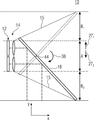
도 1b는 다중-조리개 이미징 디바이스(10)의 개략적인 측단면도를 도시하며, 여기서 이미지 센서 구역들(24a 및 24e) 뿐만 아니라 광학기기들(64a 및 64e)을 통한 단면이 예시적으로 예시되어 있다. 광학 경로들(26a 및 26e)을 편향시키기 위한 광학 경로들(26a 및 26e)에 관한 빔-편향 수단(18)의 경사는, 빔-편향 수단(18)이 두께 방향 y를 따라 광학기기들(64a 및 64e)에 관한 그리고 x 방향을 따른 가변, 즉 증가 또는 감소 거리를 포함한다는 사실을 유발할 수 있다. 광학 채널들의 광학 경로들의 발산 빔들은 바람직하게는, 적어도 90%, 적어도 95%, 또는 적어도 99.5%, 이상적으로는 100%의 정도로 빔-편향 수단(18)을 타격한다. 어레이(14)의 광학 채널들 각각 및 그에 따른 수 개의 라인들에 걸친 수 개의 광학 채널들의 조합은, 예를 들어 어레이(14)의 에지 빔들(15)에 의해 표시된 바와 같이 광학 경로들의 발산을 포함할 수 있다. 빔-편향 수단(18)의 경사와 조합된 x 방향을 따른 발산 또는 빔 확장은, 이미지 센서(12) 및 어레이(14)에 기인하는 다중-조리개 이미징 디바이스(10)의 치수 A에 부가하여, 광학기기들(64a 내지 64e)에 관한 빔-편향 수단(18)의 그리고/또는 이미지 센서(12)의 오버행(B 또는 B1)이 광학 채널들의 광학 경로들을 완전히 편향시키도록 요구된다는 사실을 유발한다. 불완전한 편향은 이미지 품질의 손실을 유발할 수 있다.1B shows a schematic side cross-sectional view of a
빔-편향 수단(18)의 예시된 배향에 대해, 이것은, 광학 경로들(26a 및 26e)을 뷰잉 방향(271)으로 편향시키기 위해 A 및 부가적으로는 B(A+B)의 다중-조리개 이미징 디바이스(10)에 대한 전체 설치 공간 요건을 초래한다.Beam - with respect to the illustrated orientation of the deflection means 18, which, optical paths (26a and 26e), the viewing direction A and add to deflect the (27 1) is less by a multiple of B (A + B) - Aperture Imaging This results in an overall installation space requirement for the
도 1c는, 예를 들어 빔-편향 수단(18)이 다중-조리개 이미징 디바이스(10)의 뷰잉 방향(271)과 뷰잉 방향(272) 사이에서 스위칭하기 위해 회전 움직임(38)을 실행하는(이는 빔-편향 수단(18)이 회전 축(44)을 중심으로 회전된다는 것을 의미함) 이론적인 상태의 다중-조리개 이미징 디바이스(10)의 개략적인 측단면도를 도시한다. 뷰잉 방향들(271 및 272)은 ±30°, ±15°, 또는 ±5°의 허용오차 범위에서 서로를 향해 반전 또는 역평형되도록 배열된다. 두께 방향 y를 따라, 다중-조리개 이미징 디바이스(10)의 오버행은 이제 다른 방향 또는 뷰잉 방향(272)을 따르도록 요구된다. 어레이(14)의 이동되지 않은 상태에서, 제1 뷰잉 방향(271)을 따른 제1 오버행(B1) 및 제2 뷰잉 방향(272)을 따른 제2 오버행(B2)은 뷰잉 방향들(271 및 272) 둘 모두를 제공하기 위해 요구되며, 여기서 B1=B2는 대칭적인 경우에 적용될 수 있다.Figure 1c is, for example, the beam-deflecting means (18) is a multi-between the viewing direction of the diaphragm imaging device 10 (27 1) and the viewing direction (27 2) which performs a rotation movement (38) to switch (This means that the beam-deflecting means 18 is rotated about the
도 1d는 일 실시예에 따른 다중-조리개 이미징 디바이스(10)의 개략적인 측단면도를 도시하며, 여기서 어레이(14)는 y 방향을 따라 조정 움직임(111)을 실행했다. 예를 들어, 이미지 센서 구역들(24a 및 24e)은 또한, 이미지 센서(12)에 대한 어레이(14)의 일정한 상대적인 위치를 유지하도록 이동될 수 있다. 이것은, 이미지 센서, 어레이 광학기기 및 그에 따른 광학 축들의 수직 위치가 가변적일 수 있다는 것을 의미한다. 대안적으로, 다른 조치들, 이를테면 어레이(14)와 이미지 센서(12) 사이의 부가적인 빔 편향 및/또는 사이즈의 관점들에서의 이미지 센서(12)의 여분의 구현을 사용함으로써, 이미지 센서(12)의 움직임이 생략될 수 있다.1D shows a schematic side cross-sectional view of a
측방향 조정 움직임(111)과 조합하여, 빔-편향 수단(18)은 또한 y 방향에 평행하게 측방향으로 이동될 수 있다. 조정 움직임(111)과 관련된 빔-편향 수단(18)의 움직임(17)의 정도는 20%, 10% 또는 5%의 허용오차 범위에서 조정 움직임(111)의 정도와 동일할 수 있다. 따라서, 뷰잉 방향(271) 내지 뷰잉 방향(272) 사이에서 스위칭하기 위한 빔-편향 수단(18) 사이의 스위칭 움직임은 회전 움직임(38) 및 부가적으로는 움직임 방향 y를 따른 빔-편향 수단(18)의 병진이동 움직임(17)을 포함할 수 있다. 조정 움직임(111)은 어레이(14)에 관련된 추가적인 병진이동 움직임을 포함할 수 있다. 어레이(14)는 빔-편향 수단(18)과 동일한 움직임 방향을 따라 이동할 수 있다. 예를 들어, 제2 뷰잉 방향(272)으로 스위칭하기 위한 스위칭 움직임 동안, 조정 움직임(111) 및 병진이동 움직임(17)은 다른 뷰잉 방향(271)을 따라 실행될 수 있다. 이미지 센서 구역들(24''a 및 24''e) 뿐만 아니라 광학기기들(64''a 및 64''e) 뿐만 아니라 빔-편향 수단(18'')에 의해 예시된 바와 같이(이는, 도 1c에 따른 컴포넌트들의 변화되지 않은 위치를 도시함), 다중-조리개 이미징 디바이스(10)의 설치 공간 요건은 도 1c의 이론적인 상태와 비교하여 최대 오버행(B1 또는 B2)의 정도까지 두께 방향 y를 따라 절약될 수 있다.In combination with the lateral adjustment movement 1 1 1 , the beam-deflecting means 18 can also be moved laterally parallel to the y direction. Beam associated with the adjusting movement (11, 1) the degree of
어레이(14)의 광학 경로들이 각각, 예를 들어, 뷰잉 방향들(271 및 272)이 서로에 관해 180°의 각도를 포함하고 어레이(14)가 뷰잉 방향들(271 및 272)에 관해 90°의 각도로 배열되는 경우에 따라, 빔-편향 수단(18) 상에 타격되기 전에 뷰잉 방향에 대해 대칭적인 방식으로 편향되면, 두께 방향 y를 따른 빔-편향 수단(18)의 위치 또는 측방향 치수는 광학 경로들을 뷰잉 방향들(271 및 272)로 편향시키기 위한 회전 위치들에서 적어도 20%, 적어도 80%, 또는 적어도 90%의 정도와 동일하거나 또는 적어도 동일할 수 있다. 이것은, 라인-연장 방향에 평행한, 예를 들어 이미지 센서(12)와 어레이(14) 사이의 광학 경로의 코스에 평행한 또는 이미지 센서(12)의 주요 측부에 평행한 평면으로의 빔-편향 수단의 투영이 이러한 정도로 회전 위치들 둘 모두에서 동일하고(중첩함), 100% 동일할 경우 일치한다는 것을 의미한다.The optical paths of the
병진이동 조정 움직임(111)의 예시된 경우에서, 설치 공간 요건의 절약은 병진이동 움직임(17)을 통한 빔-편향 수단(18)의 시프트에 의해 설명될 수 있으며, 이는, 설치 공간이 여러 번 사용되므로, 스위칭 움직임으로 인해 요구되는 빔-편향 수단의 움직임 범위의 일부가 도 1c에 따른 이동가능하지 않은 어레이와 비교하여 감소되지만, 도 1c의 이론적인 상태에서, 각각의 중첩(B1 및 B2)이 이를 위해 제공될 개별 설치 공간에서 배열되는 것을 가능하게 한다. 조정 움직임은 이러한 측방향 움직임(17)으로 조정되는 어레이(14)의 움직임인 것으로 이해될 수 있다. 따라서, 어레이(14)는 어레이(14)와 빔-편향 수단(18) 사이의 상대적인 위치를 조정하도록 이동될 수 있다. 아래에서 논의되는 바와 같이, 어레이(14)의 회전 움직임을 생성함으로써 동일한 것이 또한 획득될 수 있다.In the illustrated case of the translation adjustment movement 1 1 1 , the saving of installation space requirements can be explained by the shift of the beam-deflecting means 18 through the
따라서, 하우징 내에서의 다중-조리개 이미징 디바이스(10)의 요구되는 설치 높이 및/또는 치수는, 두께 D가 이미지 센서(12) 및 어레이(14)의 배열의 높이보다 작고 오버행(B)의 2배라는 조건을 만족할 수 있으며, 이는 다음이 적용될 수 있다는 것을 의미한다:Thus, the required installation height and / or dimension of the
D < A+2BD <A + 2B
도 1e 및 도 1f는 제1 회전 위치 및 제2 회전 위치에 있는 다중-조리개 이미징 디바이스(10')의 개략적인 사시도를 도시한다. 도 2a 내지 도 2c와 관련하여 설명되는 다중-조리개 이미징 디바이스(10)에 관한 다른 수정들 이외에, 어레이(14)는 단일-라인 방식으로 형성되며, 이는 어레이(14)의 광학기기들(64)이 단일 라인으로 위치된다는 것을 의미한다. 광학기기들(64)은 캐리어 및/또는 렌즈 홀더를 통해 서로 기계식으로 연결될 수 있으므로, 어레이(14) 내의 광학기기들(64)의 상호 움직임은 어레이(14)의 움직임/액추에이션에 의해 가능하다. 대안적으로, 각각의 광학기기(64) 또는 그의 렌즈(19a 내지 19c)는 개별적으로 지지 및/또는 이동될 수 있다. 조합 솔루션들이 또한 가능하며, 예를 들어 여기서, 상호 캐리어 및/또는 연결된 렌즈 홀더는 광학기기들(64)의 상호 움직임을 획득하기 위해 구현된다. 예를 들어, 이것은 이동 캐리지 등에서 발생할 수 있다. 부가적으로, 추가적인 액추에이터들이 제공될 수 있으며, 이는, 예를 들어 채널-개별적인 포커싱을 제공하기 위해 렌즈들의 채널-개별적인 움직임을 가능하게 한다. 채널-전역(channel-global) 포커싱이 또한, 수정 없이 모든 렌즈들의 상호 움직임을 통해 획득될 수 있다는 것이 이해된다.1E and 1F show schematic perspective views of a multi-aperture imaging device 10 'in a first rotational position and a second rotational position. In addition to other modifications to the
일 실시예에 따르면, 빔-편향 수단(18)은 스위칭 움직임 동안, 회전 축(44)을 중심으로 한 회전 움직임(38)만을 실행하도록 구성될 수 있다. 이러한 경우, 회전 축 또는 회전 축(44)은, 예를 들어 패시트 또는 빔-편향 수단의 y-확장의 중심에서 두께 방향 y로, 즉 (A+B)/2에 배열될 수 있으며, A+B는 두께 방향 y를 따른 빔-편향 수단(18)의 전체 확장을 지칭한다. 어레이(14)의 틸팅되지 않은 정상 위치에서, 두께 방향 y는 어레이(14)의 라인-연장 방향에 수직하게 그리고 이미지 센서(12)와 어레이(14) 사이의 광학 경로들의 코스에 수직하게 배열될 수 있다. 회전 축(44)을 중심 상에 중심설정하는 것은 가능한 정확하게 수행될 수 있지만; 20%, 10%, 또는 5%의 허용오차 범위 내에서 여전히 유리하다. 이것은, 예를 들어 스위칭 움직임이 회전 움직임(38)에 의해 배타적으로 실행된다는 것을 의미하며, 여기서 다중-조리개 이미징 디바이스의 두께 방향을 따른 회전 움직임(38)의 회전 축은 두께 방향 y를 따른 빔-편향 수단(18)의 가장 큰 확장에 관해 20%의 허용오차 범위 내에서 중심설정될 수 있다.According to one embodiment, the beam-deflecting means 18 may be configured to perform only the
도 1f는 조정 움직임(111)을 실행한 이후의 다중-조리개 이미징 디바이스(10')를 예시한다. 빔-편향 수단(18)은 도 1d와 관련하여 설명된 바와 같이, 그에 따라 이동되었다. 오버행(B2)이 또한 제2 뷰잉 방향(272)을 따라 배열될 수 있다. B1 = B2 = B는, 예를 들어 다중-조리개 이미징 디바이스(10')의 대칭적인 구현에서 적용될 수 있다. 단일 오버행이 충분할 수 있으므로, 전체 설치 공간 요건 A+B가 낮을 수 있으며, 이는 도 1a에 따른 이중 제공과 비교하여 적을 수 있다. 이것은, 스위칭 움직임이 빔-편향 수단(18)의 회전 움직임(38)을 포함한다는 것을 의미하며, 여기서 조정 움직임(11)은, 라인-연장 방향 z에 수직이고 다중-조리개 이미징 디바이스의 두께 방향 y에 평행한 움직임 방향/두께 방향 y에 따른 어레이(14)의 병진이동 움직임(111)을 포함한다.1F illustrates the
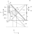
도 2a는, 다시 설명되고 다중-조리개 이미징 디바이스(10)와 비교하여 수 개의 변화들을 포함하는 다중-조리개 이미징 디바이스(10')의 개략적인 측단면도를 도시하며, 그 변화들은 각각 선택적으로 및 개별적으로 및 독립적으로 구현될 수 있다. 어레이(14)는 단일-라인 어레이로서 형성될 수 있으며, 이는 도 1a의 뷰에서, 예를 들어, 개별 및 단일 라인에서의 오직 광학기기들(64a 내지 64d) 또는 임의의 다른 수의 광학기기들의 배열로서 이해될 수 있다. 더욱이, 광학기기(64)는 빔 형성을 위해 함께 사용되는 복수의 광학기기 엘리먼트들(19a, 19b 및/또는 19c)을 포함할 수 있다. 어레이(14) 및 이미지 센서(12)는 어레이(14) 및 이미지 센서(12)의 상호 움직임을 가능하게 하기 위해 상호 하우징에 배열될 수 있다. 더욱이, 빔-편향 수단(18)은, 서로를 향해 경사져 있는 주요 측부들(174a 및 174b)을 포함하는 개별 또는 복수의 패시트들로서 형성될 수 있다.FIG. 2A shows a schematic cross-sectional side view of a
다중-조리개 이미징 디바이스(10')는 단지 더 양호한 제시를 위해 선택된다. 대안적으로, 다중-조리개 이미징 디바이스(10)가 또한, 조정 움직임(112)과 관련된 설명을 위해 임의의 제한 효과들 없이 사용될 수 있다. 도 2a에서, 빔-편향 수단(18)의 배향을 통해, 다중-조리개 이미징 디바이스(10')는 뷰잉 방향(271)을 따른 캡처가 가능하도록 구현된다.The multi-aperture imaging device 10 'is selected for better presentation only. Alternatively, a multi-aperture imaging the
도 2b에서, 빔-편향 수단(18)은 회전 축(44)을 중심으로 한 회전 움직임(38)을 이용하여 회전된다. 예를 들어, 이것은 시계 방향으로 발생할 수 있다. 조정 움직임(112)은 또한, 예를 들어 하우징(21)을 이동시키는 것에 의한 어레이(14)의 회전 움직임을 포함한다. 도 2a 및 도 2b에서, 조정 움직임(112)은, 빔-편향 수단(18) 상에 타격하기 전에 어레이(14)의 대칭적인 뷰잉 방향에 관해, 도 1b, 도 1c 및 도 1d에 예시된 바와 같이, 예를 들어 광학 경로들(26)의 사전-경사(pre-inclination)가 획득되어, 이들이 기준 방향에 관해, 예를 들어 x-방향에 평행하게 각도 y1 및/또는 y2로 타격되므로, 빔-편향 수단(18)에 의한 광학 경로들(26)의 편향은 x-방향에 평행한 광학 경로들(26)의 중심 빔들의 코스와 비교하여 더 작을 수 있다는 사실을 유발할 수 있다.In Fig. 2b, the beam-deflecting means 18 is rotated using a
예를 들어, 어레이(14) 및 이미지 센서(12)는 하우징(21)을 통해 서로 기계식으로 커플링될 수 있으며, 조정 움직임(11)을 상호 실행하도록 구성될 수 있다. 하우징(21)은 이동 캐리지 등으로 지칭될 수 있다. 이것은 또한, 빔-편향 수단(18)에 의한 뷰잉 방향의 전체 영향 대신에, 뷰잉 방향들(271 및 272)을 스위칭하는 것의 일부가 어레이(14)의 움직임에 의해 획득될 수 있는 것으로 이해될 수 있다. 예를 들어, 뷰잉 방향들(271 및 272)이 서로 반대이도록 배열되고 180°의 각도를 포함하면 그리고 빔-편향 수단(18)이 서로를 향해 평행하게 배열되는 주요 측부들을 갖는 양 측부들 상에서 반사되는 미러에 의해 배열되면, 도 1b에 예시된 바와 같이, 90°의 회전은 스위칭 움직임을 야기하기 위해 도 1b에 따른 구성에서 필요하다. 예를 들어, 이것은 x-방향에 관해 ±45°의 배향을 유발한다. 어레이(14)의 대응하는 회전 움직임들을 사용하여 조정 움직임(112)을 적용함으로써, 이러한 배향 또는 경사는 45°-y1 또는 45°-y2로 감소될 수 있으므로, 전체 회전 움직임(38)은 90°-(y1+y2)로 감소될 수 있다.For example, the
서로를 향해 경사져 있는 주요 표면들(174a 및 174b)을 사용함으로써, 추가적인 감소가 가능하다. 각도들 y1 및 y2에 관한 광학 경로들(26)의 사전-경사에 의해, 빔-편향 수단(18)의 회전을 위한 더 낮은 요건이 뷰잉 방향들(271 및 272) 사이에서 스위칭하기 위해 필요할 수 있다. 이러한 더 작은 범위의 회전은 어레이(14)에 관한 빔-편향 수단(18)의 더 작은 오버행을 유발하며, 이는 C로 표시된다. 도 1a 내지 도 1d에 따른 빔-편향 수단(18)을 사용하는 경우라도, B > C가 적용될 수 있다. 이것은, 조정 움직임(112)에 의해 빔-편향 수단(18)의 회전 범위를 감소시킴으로써 더 작은 사이즈의 설치 공간 요건이 y-방향을 따라 획득될 수 있다는 것을 의미한다. 이것은, 제1 회전 위치로부터 제2 회전 위치로의 스위칭 움직임이 빔-편향 수단(18)의 회전 움직임(38)을 포함할 수 있고, 조정 움직임(112)이 추가적인 회전 움직임을 포함할 수 있다는 것을 의미한다. 2개의 회전 움직임들은 바람직하게는 동일한 방향에서, 예를 들어 둘 모두 시계 방향에서 또는 둘 모두 반시계 방향에서 발생할 수 있다. 빔-편향 수단(18)이 회전 움직임(38)을 통해 회전되고 어레이(14)가 조정 움직임(112)을 통해 회전되는 각도 값들의 합들은 20%, 10%, 또는 5%의 허용오차 범위 내에서 90°의 각도 합을 초래할 수 있다.By using the
중첩들(C1 및 C2)이 각각 양의 y-방향을 따라 그리고 음의 y-방향을 따라 필요하지만, 이들은 중첩(B, B1 또는 B2)과 비교하여 작아서, 유리한 구현을 유발한다. 예를 들어, 다음이 적용될 수 있다:Although the overlaps C 1 and C 2 are required along the positive y-direction and the negative y-direction, respectively, they are small compared to the overlap (B, B 1 or B 2 ), resulting in an advantageous implementation. . For example, the following may apply:
C = C1 = C2 > B = B1 = B2 C = C 1 = C 2 > B = B 1 = B 2
따라서, A+C1+C2 및 A+2C의 필요한 치수들이 또한 각각 다음의 조건을 만족시킬 수 있다:Therefore, the required dimensions of A + C 1 + C 2 and A + 2C can also satisfy the following conditions respectively:
D < A+2BD <A + 2B
도 1a 내지 도 1d, 도 2a 및 도 2b에 기초하여, 조정 움직임(11)이 병진이동 움직임(111) 또는 회전 움직임(112)을 포함하는 구현들이 예시적으로 설명되었다. 실시예들에 따르면, 병진이동 움직임(111) 및 회전 움직임(112)이 실행되도록 조정 움직임(11)을 실행하는 것이 또한 가능하다. 예를 들어, 어레이(14)의 회전은 도 1b 및 도 1d에서, 예를 들어 액추에이터(11)에 의해 구현될 수 있다. 대안적으로 또는 부가적으로, 도 2a 및 도 2b에 따른 어레이(14) 및/또는 하우징(21)은 부가적으로, 조정 움직임(111)에 따라, 예를 들어 뷰잉 방향(271)과 뷰잉 방향(272) 사이에서 스위칭할 경우 양의 y-방향으로 이동될 수 있다. 이로 인해, 2개의 중첩 공간들(B1 또는 B2 및 C1 또는 C2) 중 하나를 회피하는 것에 부가하여 나머지 중첩 구역의 감소가 각각 획득될 수 있다.Based on FIGS. 1A-1D, 2A and 2B, implementations have been described in which the adjustment motion 11 includes a translational motion 1 1 1 or a rotational motion 1 2 1 . According to embodiments, to perform a translation movement (11, 1) and the rotary movement (11, 2) adjust the movement 11 so that the execution is also possible. For example, rotation of the
이것은, 제1 회전 위치로부터 제2 회전 위치로의 스위칭 움직임이 빔-편향 수단의 제1 회전 움직임 및 제1 움직임 방향을 따른 빔-편향 수단의 병진이동 움직임, 즉 회전 움직임(38) 및 병진이동 움직임(17)을 포함한다는 것을 의미한다. 조정 움직임은 움직임 방향을 따른 어레이의 병진이동 움직임, 즉 조정 움직임(111)을 포함할 수 있으며, 부가적으로 회전 움직임, 즉 조정 움직임(112)을 포함할 수 있다.This means that the switching movement from the first rotational position to the second rotational position is the first rotational movement of the beam-deflecting means and the translational movement of the beam-deflecting means along the first direction of movement, ie
다시 말하면, 빔-편향 수단의 회전 움직임에 부가하여, 이미지 센서 및 어레이 광학기기로 이루어진 유닛은 다중-조리개 카메라의 상이한 뷰잉 방향을 달성하기 위해 이동될 수 있다. 지금까지, 후자는 적어도 두께 방향에서 정지되어 있었다. 미러 패시트 또는 미러의 요구되는 경사진 위치의 결과로서, 어레이 광학기기로부터 멀어지는 쪽을 향하는 미러 패시트의 에지는 렌즈 어레이를 넘어 두께 방향으로 돌출되고, 그에 따라 본질적으로 설치 높이를 결정한다. 어레이 광학기기를 향하는 에지는, 어레이 광학기기의 렌즈들에 의해 미리 결정된 설치 높이를 넘어 더 작은 정도로 돌출되거나 또는 전혀 돌출되지 않는다. 어레이의 고정된 광학 축들에 관해, 렌즈들은 두께 방향으로 거리들 1/2 A+B을 형성한다. 빔-편향 수단을 회전시킴으로써 뷰잉 방향을 스위칭할 경우 유사한 이미지가 초래된다. 전체 구조에 관해, 2개의 뷰잉 방향들의 원하는 실현을 위해 A+2B의 설치 높이가 초래된다. 실시예들에 따르면, 빔-편향 수단의 회전에 부가하여, 이미지 센서들 및 어레이 광학기기로 이루어진 유닛이 이동되며, 이는 조정 움직임(11)이 실행된다는 것을 의미한다. 한편으로, 이것은, 조정 움직임(112)과 비교하여 두께 방향을 따른 병진이동 움직임(111), 라인-연장 방향에 평행한 회전 축에 대한 회전 움직임, 또는 이들의 조합을 포함할 수 있다. 그 결과, 요구되는 설치 높이는 A+B까지의 값으로 감소될 수 있다. 오토포커스 및/또는 광학 이미지 안정화를 구현하기 위한 부가적인 움직임들을 실현하기 위해, 이미지 센서들 및 어레이 광학기기로 이루어진 유닛을 이동시키도록 추가적인 드라이브들이 배열될 수 있다. 실시예들에 따른 다중-조리개 이미징 디바이스들은 오토포커스 및/또는 이미지 안정화 없이 구현될 수 있다. 대안적으로 또는 부가적으로, 액추에이터(13)는 포커싱 및/또는 이미지 안정화를 위한 대응하는 움직임을 제공하도록 구성될 수 있다.In other words, in addition to the rotational movement of the beam-deflecting means, the unit consisting of the image sensor and the array optics can be moved to achieve different viewing directions of the multi-aperture camera. So far, the latter has been stopped at least in the thickness direction. As a result of the mirror facet or the desired inclined position of the mirror, the edge of the mirror facet facing away from the array optics projects in the thickness direction beyond the lens array, thereby essentially determining the installation height. The edge towards the array optics protrudes to a smaller extent beyond the predetermined installation height by the lenses of the array optics or does not project at all. With respect to the fixed optical axes of the array, the lenses form distances 1/2 A + B in the thickness direction. A similar image results when switching the viewing direction by rotating the beam-deflecting means. With regard to the overall structure, the installation height of A + 2B is brought about for the desired realization of the two viewing directions. According to embodiments, in addition to the rotation of the beam-deflecting means, a unit consisting of image sensors and array optics is moved, which means that an adjustment motion 11 is performed. On the one hand, this translational movement along the thickness direction as compared with the adjustment movements (11, 2) movement (11 1), the line may include a rotational movement about a rotational axis parallel to the extending direction, or a combination thereof. As a result, the required installation height can be reduced to values up to A + B. Additional drives can be arranged to move a unit consisting of image sensors and array optics to realize additional movements to implement autofocus and / or optical image stabilization. Multi-aperture imaging devices according to embodiments may be implemented without autofocus and / or image stabilization. Alternatively or additionally, the
도 2c는, 예를 들어 스위칭 움직임 동안 획득될 수 있고 그리고/또는, 예를 들어 대기 동안 다중-조리개 이미징 디바이스(10)의 비활성 상태에서 획득될 수 있는 제3 회전 위치에 있는 다중-조리개 이미징 디바이스(10')의 개략적인 측단면도를 도시한다. 예시된 회전 위치에서, 두께 방향 y를 따른 빔-편향 수단(18)의 치수는 하우징(21) 및/또는 이미지 센서(12) 및/또는 어레이(14)의 치수보다 작거나 그와 동일할 수 있다. 이것은, 다중-조리개 이미징 디바이스(10')의 두께가 바람직하게는 이러한 상태에서 빔-편향 수단(18)에 의해 결정되지 않는다는 것을 의미한다. 이것은 다중-조리개 이미징 디바이스를 얇은 방식으로 저장하는 것을 가능하게 한다. 이것은, 회전 위치, 및 그에 따른 이미지 센서, 어레이 광학기기 및 그에 따른 광학 축들의 수직 위치가 가변적일 수 있다는 것을 의미한다.2C is a multi-aperture imaging device in a third rotational position that can be obtained, for example, during a switching movement and / or can be obtained, for example, in an inactive state of the
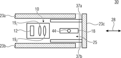
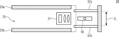
도 3a는 일 실시예에 따른 디바이스(30)의 개략적인 측단면도를 도시한다. 디바이스(30)는, 다중-조리개 이미징 디바이스(10)가 측부 표면들(23a, 23b 및 23c)을 갖는 하우징(23) 내에 배열되는 제1 동작 상태를 포함하며, 예를 들어 측부 표면들(23a 및 23b)은 주요 측부들, 예를 들어 전방 측부 및 후방 측부이다. 예를 들어, 디바이스(30)는 스마트폰 또는 태블릿 컴퓨터와 같은 모바일 텔레폰이어서, 주요 측부들 중 적어도 하나가 디스플레이를 포함할 수 있다. 측부 표면(23c)은 보조 측부일 수 있고, 커버로 지칭될 수 있다. 커버(23c)를 열리게 플립(flip)하거나 이동시킴으로써, 다중-조리개 이미징 디바이스(10) 및/또는 빔-편향 수단(18)은, 예를 들어 다중-조리개 이미징 디바이스(10)가 시야들의 이미지들을 캡처하는 제2 동작 상태를 획득하기 위해 하우징 볼륨(25) 외부로의 빔 편향을 가능하게 하도록 하우징 볼륨(25) 밖으로 완전히 또는 부분적으로 이동될 수 있다. 제1 동작 상태에서, 빔-편향 위치는 도 2c와 관련하여 설명되는 바와 같이, 제1 회전 위치와 제2 회전 위치 사이의 중심 위치를 포함할 수 있다. 빔-편향 수단(18)은 하우징 내의 제1 위치를 포함한다.3A shows a schematic side cross-sectional view of a
디바이스(30)는 커버(23c)에 연결될 수 있는 적어도 부분적으로 투명한 커버들(37a 및 37b)을 포함한다. 따라서, 커버들(37a 및 37b)은 병진이동 움직임 방향(28)을 따라 빔-편향 수단(18)과 함께 이동가능할 수 있으므로, 빔-편향 수단(18)은 하우징(23) 밖으로 부분적으로 또는 완전히 이동된다. 적어도 부분적으로 투명한 커버들(37a 및 37b)은 빔-편향 수단(18)과 하우징(23) 사이의 빔-편향 수단의 상이한 측부들에서 예시된 제1 위치에 배열될 수 있다. 이것은 빔-편향 수단(18)이 커버들(37a 및 37b) 사이에 배열될 수 있다는 것을 의미한다.The
제1 동작 상태에서, 커버들(37a 및 37b)은 하우징 볼륨(25) 내에 부분적으로 또는 완전히 배열될 수 있다. 예를 들어, 커버들(37a 및 37b)은 이동 캐리지에 배열될 수 있거나 또는 이동 캐리지의 투명한 구역들일 수 있다. 하우징(23) 밖으로의 또는 하우징(23) 내로의 빔-편향 수단의 움직임들 동안, 어레이(14) 및/또는 이미지 센서(12)는 정지상태로 유지될 수 있거나 또는 측방향 움직임 방향(28)을 따라 또한 이동될 수 있어서, 예를 들어, 이미지 센서(12), 어레이(14) 및 빔-편향 수단(18) 사이의 거리는 변화되지 않게 유지된다. 이러한 경우, 이동 캐리지는 또한 이미지 센서(12) 및/또는 어레이(14)를 포함할 수 있다.In the first operating state, the
도 3b는 디바이스(30)의 개략적인 측단면도를 도시하며, 여기서 빔-편향 수단(18)은 제1 위치와 제2 위치 사이의 중간 위치를 포함한다. 예를 들어, 빔-편향 수단의 중간 위치는 하우징 볼륨(25) 내로의 또는 하우징 볼륨(25) 밖으로의 빔-편향 수단(18)의 후퇴 또는 연장 동안 획득될 수 있다. 빔-편향 수단(18)은 하우징 볼륨(25) 밖으로 부분적으로 이동된다.3B shows a schematic side cross-sectional view of the
도 3c는 디바이스(30)의 개략적인 측단면도를 도시하며, 여기서 빔-편향 수단(18)은 제2 위치를 포함하고, 즉 예를 들어, 빔-편향 수단(18)은 하우징 볼륨(25)으로부터 완전히 연장된다. 적어도 부분적으로 투명한 커버들(37a 및 37b)은, 하우징의 측부 표면들(23a 및 23b) 사이의 비교가능한 거리보다 작은 서로를 향한 거리(E1)를 포함한다.3c shows a schematic side cross-sectional view of the
도 3d는 디바이스(30)의 개략적인 측단면도를 도시하며, 여기서 적어도 부분적으로 투명한 커버들(37a 및 37b)은 도 3a 내지 도 3c와 비교하여 확대된다. 적어도 부분적으로 투명한 커버들(37a 및/또는 37b)은 각각, 다른 적어도 부분적으로 투명한 커버들(37a 및 37b)로부터 멀어지는 쪽을 향하는 병진이동 움직임을 따라, 예를 들어 두께 방향 y에 평행하게, 즉 양의 또는 음의 y 방향을 따라 이동가능할 수 있다. 도 3a 내지 도 3c에 예시된 적어도 부분적으로 투명한 커버들(37a 및 37b)의 상태는 후퇴된 또는 접힌 상태로서 이해될 수 있다. 도 3d에 예시된 상태는 연장된 또는 펼쳐진 상태로서 이해될 수 있으며, 여기서 적어도 부분적으로 투명한 커버들(37a 및 37b) 사이의 거리(E2)는 거리(E1)와 비교하여 변화되고, 예를 들어 증가되며, 즉 E2 > E1가 적용된다. 예를 들어, 거리(E2)는 하우징(23)의 비교가능한 측부들 사이의 거리보다 크거나 그와 동일할 수 있다. 빔-편향 수단(18)은 광학 채널들의 광학 경로들을 편향시켜, 그들이 적어도 부분적으로 투명한 커버들(37a 및/또는 37b)을 통과하도록 이루어진다.3D shows a schematic side cross-sectional view of the
도 3a의 제1 동작 상태 또는 도 3b 또는 도 3c의 상태와 비교하여, 빔-편향 수단(18)의 각도 배향은, 다중-조리개 이미징 디바이스의 광학 경로에 의해 사용되는 빔-편향 유닛의 영역이 제1 동작 상태와 비교하여 증가하고 제1 회전 위치 또는 제2 회전 위치가 획득되도록 변화될 수 있다. 대안적으로 또는 부가적으로, 증가된 거리(E2)는 더 큰 범위의 회전 움직임(38)을 가능하게 할 수 있다. 회전 움직임(38)을 이용하여, 빔-편향 수단(18)은 적어도 제1 회전 위치와 추가적인 회전 위치 사이에서 스위칭가능할 수 있으며, 여기서 각각의 위치는 다중-조리개 이미징 디바이스의 뷰잉 방향에 할당될 수 있다. 빔-편향 수단(18)의 회전은 유사하게 또는 쌍안정(bistable) 방식으로 또는 다중-안정 방식으로 발생할 수 있다. 다중-조리개 이미징 디바이스의 뷰잉 방향을 변화시키기 위한 회전 움직임(38)은 광학 이미지 안정화를 위한 빔-편향 수단(18)의 회전 움직임과 조합될 수 있다. 커버들(37a 및/또는 37b)은 다중-조리개 이미징 디바이스의 다른 컴포넌트들을 캡슐화할 수 있다.Compared to the first operating state of FIG. 3A or the state of FIG. 3B or 3C, the angular orientation of the beam-deflecting means 18 is such that the area of the beam-deflecting unit used by the optical path of the multi-aperture imaging device is It can be increased compared to the first operating state and changed to obtain a first rotational position or a second rotational position. Alternatively or additionally, the increased distance E 2 can enable a larger range of
다중-조리개 이미징 디바이스는 거리(E2) 내에서 스위칭 움직임 및 조정 움직임을 수행할 수 있다. 따라서, 예를 들어, 커버들(37a 및 37b)의 연장은 조정 움직임에 기초하여, 도 1a 내지 도 1d 및 도 2a 내지 도 2c의 논의들에 따라 작을 수 있는 어레이(14) 및/또는 이미지 센서(12)에 대한 움직임 공간을 제공할 수 있으며, 이는 또한, 두께 방향을 따른 디바이스(30)의 작은 확장을 가능하게 한다.The multi-aperture imaging device is capable of performing switching movements and steering movements within a distance E 2 . Thus, for example, the extension of the
반대쪽에 배열된 커버들(37a 및/또는 37b) 또는 이들의 투명한 구역들은 스위칭가능한 다이어프램(33a 및/또는 33b)을 포함할 수 있으므로, 스위칭가능한 다이어프램(33a 및 33b)은, 예를 들어 빔-편향 수단의 임의의 다른 방향 위에 그리고/또는 아래에 또는 그를 따라 도입된다. 다이어프램(33a 및 33b)은 카메라의 동작 상태 또는 뷰잉 방향에 따라 스위칭될 수 있다. 예를 들어, 사용되지 않은 다중-조리개 이미징 디바이스의 개개의 뷰잉 방향은 미광의 진입을 감소시키기 위하여 다이어프램(33a 및 33b)에 의해 적어도 부분적으로 폐쇄될 수 있다. 예를 들어, 다이어프램(33a 및 33b)은 기계식으로 이동되거나 또는 전기변색(electrochromic)일 수 있다. 다이어프램(33a 및 33b)에 의해 영향받는 구역들은 부가적으로, 동일한 것이 사용되지 않는 경우 광학 구조를 덮는 스위칭가능한 다이어프램(33a 및 33b)을 제공받을 수 있다. 다이어프램(33a 및 33b)은 전기적으로 제어가능할 수 있고, 전기변색 층(시퀀스)을 포함할 수 있다. 대안적으로 또는 부가적으로, 다이어프램(33a 및 33b)은 기계식으로 이동되는 부분을 포함할 수 있다. 움직임은, 공압식, 유압식, 압전식 액추에이터들, DC 모터들, 스테퍼 모터들, 열식 액추에이터들, 정전식 액추에이터들, 전기변형식 및/또는 자기변형식 액추에이터들 또는 드라이브들을 사용하여 수행될 수 있다. 뷰잉 방향이 다이어프램을 관통하는 다중-조리개 이미징 디바이스의 상태에서, 다이어프램(33a 및 33b)은 광학 채널들의 광학 경로들이 통과하게 허용하도록 스위칭될 수 있다. 이것은, 다중-조리개 이미징 디바이스가 제1 동작 상태 및 제2 동작 상태를 포함할 수 있다는 것을 의미한다. 빔-편향 수단은 제2 동작 상태 및 제1 회전 위치에서 광학 채널들의 광학 경로를 편향시킬 수 있어서, 광학 경로는 커버(37a)의 제1 투명 구역을 통해 연장된다. 제2 동작 상태의 제2 회전 위치에서, 광학 채널들의 광학 경로는 편향될 수 있어서, 광학 경로는 커버(37b)의 제2 투명 구역을 통해 연장된다. 제1 다이어프램(33a)은 제2 동작 상태에서 광학 방식으로 제1 투명 구역을 적어도 부분적으로 광학적으로 폐쇄하도록 구성될 수 있다. 제2 다이어프램(33b)은 제1 동작 상태에서 일시적인 광학 방식으로 제2 투명 구역을 적어도 부분적으로 폐쇄하도록 구성될 수 있다. 이로 인해, 다중-조리개 이미징 디바이스의 실제 뷰잉 방향이 아닌 방향으로부터의 미광의 진입이 감소될 수 있으며, 이는 이미지 품질에 관해 유리하다. 제1 및/또는 제2 다이어프램(33a 및 33b)은 광학 채널들 중 적어도 하나, 적어도 2개, 또는 모두에 대해 동작가능할 수 있다. 예를 들어, 다중-조리개 이미징 디바이스의 적어도 하나, 적어도 2개, 또는 모든 광학 채널들은, 광학 채널들의 광학 경로가 제1 투명 구역을 통해 안내되면 제1 다이어프램을 통해 연장될 수 있고, 광학 채널들의 광학 경로가 제2 투명 구역을 통해 안내되면 제2 다이어프램을 통해 연장될 수 있다.
빔-편향 수단을 펼치기 위한 메커니즘을 병진적으로 이동시키기 위한 메커니즘과 조합하는 것이 가능하며, 즉 혼합된 형태들이 존재할 수 있다는 것이 이해될 것이다. 하우징을 펼치는 것 및/또는 빔-편향 수단을 연장시키는 것이 수행될 수 있어서, 적용가능하면, 캡처 모듈, 즉 광학 채널들, 그의 광학기기들 및/또는 이미지 센서가 하우징 볼륨 밖으로 이동된다. 빔-편향 수단의 각도의 변화는, 두께 방향으로의 다중-조리개 이미징 디바이스의 확장이 크고 그리고/또는 빔-편향 수단이 "전방" 및 "후방"을 향해 방해없는 방식으로 광학 경로를 편향시킬 수 있는 것을 가능하게 할 수 있다. 커버들(37)과 같은 커버링 유리들이 또한 펼쳐진 또는 연장된 엘리먼트들에 관해 고정될 수 있다. 커버링 유리들은 임의의 평면형 또는 비-평면형 표면 영역들을 포함할 수 있다.It will be understood that it is possible to combine the mechanism for expanding the beam-deflection means with the mechanism for translationally moving, ie mixed forms may exist. Unfolding the housing and / or extending the beam-deflecting means can be performed, where applicable, the capture module, ie the optical channels, its optics and / or the image sensor, is moved out of the housing volume. The change in the angle of the beam-deflecting means is such that the expansion of the multi-aperture imaging device in the thickness direction is large and / or the beam-deflecting means can deflect the optical path in an unobstructed way toward the “front” and “rear”. You can make it possible. Covering glasses such as covers 37 can also be secured with respect to unfolded or elongated elements. The covering glasses can include any planar or non-planar surface areas.
다시 말하면, 다중-조리개 이미징 디바이스는 움직임 캐리지/이동 캐리지 상에 적어도 부분적으로 부착될 수 있고, 스마트폰과 같은 평탄한 하우징 밖으로 연장될 수 있다. 이러한 경우, 빔-편향 수단, 및 이미지 센서 및 어레이 광학기기로 이루어진 유닛은, 이미지들이 뷰잉 방향들 둘 모두에서 캡처되는 경우와 다른 위치들을 취할 수 있다. 위치설정은, 최소 설치 높이가 초래되고 빔-편향 수단의 양방향 미러링된 패시트들의 선단(tip)들 또는 빔-편향 유닛의 얇은 에지가 이러한 위치에서 어레이 광학기기를 향해 지향되는 그러한 방식으로 수행될 수 있다.In other words, the multi-aperture imaging device can be attached at least partially on the motion carriage / moving carriage and extend out of the flat housing such as a smartphone. In this case, the unit consisting of the beam-deflecting means and the image sensor and the array optics can take different positions than if the images were captured in both viewing directions. Positioning can be performed in such a way that the minimum installation height is effected and the tips of the bi-directional mirrored facets of the beam-deflecting means or the thin edge of the beam-deflecting unit are directed towards the array optics in this position. Can be.
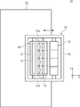
도 3e는 다중-조리개 이미징 디바이스(30)의 개략적인 평면도를 도시하며, 여기서 예시적인 이동 캐리지(43)의 기능은 하우징(23)에서 이동가능하게 배열될 수 있다. 이동 캐리지(43)는, 빔-편향 수단(18), 이미지 센서(12) 및 어레이(14)가 직접적으로 또는 간접적으로, 즉 그에 이동가능하게 배열 또는 지지되는 프레임 또는 다른 고정 구조(45)를 포함할 수 있다. 예를 들어, 빔-편향 수단(18)은 채널-개별적인 패시팅(faceting), 즉 채널 당 하나의 빔-편향 구역을 포함하며, 여기서 패시트들은 광학 경로의 채널-개별적인 편향을 획득하기 위해 서로에 관해 경사져 있을 수 있다. 빔-편향 수단(18)은 프레임(45)에 관해 회전 지지될 수 있으며, 프레임(45)의 움직임에 기초하여 그리고 프레임(45)에 관한 회전 움직임(38)에 또한 기초하여 이동될 수 있다. 컴포넌트들 중 일부, 예를 들어 이미지 센서(12) 및 어레이(14)는 이동 유닛(49)에 의해 서로 기계식으로 커플링될 수 있으므로, 이동 유닛(49)의 움직임은 그에 커플링된 컴포넌트들의 움직임을 야기한다. 이동 캐리지(43) 내에서, 예를 들어 이동 유닛(49)은 조정 움직임을 수행하고, 이와 관련하여 프레임(45)에 관한 상대적인 움직임을 실행하도록 구성될 수 있다. 대안적으로 또는 부가적으로, 예를 들어 포커싱 수단 또는 광학 이미지 안정화기의 선택적인 드라이브들 또는 액추에이터들(51a 및/또는 51b)은 동시에 이동될 수 있다. 대응하는 드라이브들(51a 및/또는 51b), 예를 들어 공압식, 유압식, 열식, 압전식, 정전식, 전기역학식, 자기변형식 또는 전기변형식 액추에이터들은 하우징(21) 내에 그리고/또는 이동 유닛(49) 내에 또는 예시된 바와 같이 하우징(21) 외부에 배열될 수 있다. 이러한 방식으로, 포커스 및/또는 이미지 안정화는 액추에이터들(51a 및/또는 51b)에 의해 제공 또는 세팅될 수 있는 한편, 이로 인해 이동되는 이동 유닛(49)은 조정 움직임을 획득하는 것에 부가하여 이동된다.3E shows a schematic top view of the
도 3f는 다중-조리개 이미징 디바이스(30)의 개략적인 평면도를 도시하며, 여기서 이동 캐리지(43) 또는 이동 유닛(49)이 수정된다. 구체적으로, 예를 들어, 액추에이터들(51a 및 51b)은 이동 유닛(49)의 일부이고, 예를 들어 하우징(21)에 배열되므로, 액추에이터들(51a 및/또는 51b)은 조정 움직임을 실행하는 동안 움직인다. 이동 유닛(49)은 어레이(14), 이미지 센서(12), 및 오토포커싱 및 광학 이미지 안정화를 위한 액추에이터들(51a/51b)을 포함할 수 있다. 이것은, 어레이(14), 이미지 센서(12) 및 광학 이미지 안정화를 위한 포커싱을 제공하기 위한 액추에이터들(51a/51b)이 서로 기계식으로 커플링되고, 조정 움직임(11)을 상호 실행하도록 이루어진다는 것을 의미한다.3F shows a schematic top view of the
이동 캐리지(43)는 하우징(23) 밖으로 전체 다중-조리개 카메라를 옆으로 연장시키는 데 사용될 수 있다. 예를 들어, 이미지 센서(12), 어레이(14), 빔-편향 유닛(18), 오토포커스 및 광학 이미지 안정화를 위한 액추에이터들, 및 적용가능하다면 커버링 유리들이 이러한 이동 캐리지에 배열되어, x-방향으로 움직인다. 조정 움직임(11)을 위해, 이미지 센서, 어레이 및 적용가능하다면 오토포커스 및/또는 광학 이미지 안정화로 이루어진 유닛은 별개의 방식으로 그리고 y를 따라, 예를 들어 이동 유닛(49)에 의해 부가적으로 이동될 수 있다.The moving
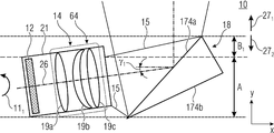
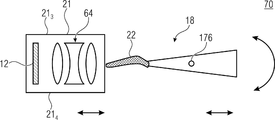
도 4는 일 실시예에 따른 다중-조리개 이미징 디바이스(40)의 개략적인 측단면도를 도시하며, 여기서 어레이(14)는 단일-라인 방식으로 형성되고, 이는 도 1의 이중-라인 어레이와는 반대로, 광학기기들(64)의 하나의 라인만이 배열될 수 있다는 것을 의미한다. 이에 관계없이, 다중-조리개 이미징 디바이스(40)는 다이어프램 구조(22)를 포함할 수 있다.FIG. 4 shows a schematic side cross-sectional view of a
슬릿(slit)(29), 즉 거리가 어레이(14)와 빔-편향 수단(18) 사이에 배열된다. 이러한 경우, 다중-조리개 이미징 디바이스(10)는 다이어프램 구조(22)가 슬릿(29)을 적어도 부분적으로 폐쇄하도록 구현된다. 이와 관련하여, 다이어프램 구조(22)는 예시된 바와 같이, 어레이(14), 또는 캐리어(47), 및/또는 빔-편향 수단(18)과 중첩할 수 있다. 이것은, 다이어프램 구조(22)가 어레이(14) 및/또는 빔-편향 수단(18)과 기계식으로 접촉할 수 있고, 빔-편향 수단(18)과 어레이(14) 사이에 공간적으로 배열되는 구역 또는 볼륨 외부에 배열될 수 있다는 것을 의미한다. 어레이(14)와의 기계식 접촉에 대한 대안으로서, 다이어프램 구조(22)는 투명 구조, 예를 들어 도 7과 관련하여 설명되는 바와 같은 투명 구조(42)와 기계식으로 접촉할 수 있다. 대안적으로, 다이어프램 구조(22)는, 다이어프램 구조가 어레이(14)와 빔-편향 수단(18) 사이에 공간적으로 위치되도록 어레이(14) 및/또는 빔-편향 수단(18)에 배열될 수 있다. 둘 모두의 경우들에서, 어레이(14)와 빔-편향 수단(18) 사이의 슬릿(29)은 적어도 부분적으로, 즉 적어도 50%, 적어도 70%, 적어도 90%, 또는 바람직하게는 전적으로 폐쇄된다.A
다이어프램 구조(22)는, 특히 현재 세팅된 뷰잉 방향의 부분 시야들에 할당된 방향들과는 상이한 방향으로부터의 광의 진입을 적어도 부분적으로 방지하도록 구성될 수 있다. 뷰잉 방향(27)에 반대로 위치 또는 배열되는 캐리어(47) 및/또는 빔-편향 수단(18)의 끝에 다이어프램 구조(22)를 배열함으로써, 뷰잉 방향(27)에 반대인 방향으로부터의 미광의 진입이 적어도 부분적으로 감소될 수 있다. 슬릿(29)이 완전히 폐쇄되면 그리고 다이어프램 구조(22)가 완전히 불투명하게 구성되면, 예를 들어 뷰잉 방향에 반대인 방향으로부터의 또는 또한 추가적인 방향들로부터의 미광의 양이 또한 완전히 감소가능할 수 있다. 미광의 감소의 증가된 양으로, 이미지 품질의 증가가 증가된 정도로 획득될 수 있다.The
다이어프램 구조(22)는 어레이들(14) 및/또는 빔-편향 수단(18) 중 적어도 하나에 고정 방식으로 기계식으로 연결되고, 그러한 방식으로 이러한 엘리먼트에 의해 지지될 수 있다. 다른 엘리먼트에서, 느슨하거나 고정된 기계식 접촉이 슬릿(29)을 폐쇄하기 위해 획득될 수 있다.The
도 5는 추가적인 실시예에 따른 다중-조리개 이미징 디바이스(50)의 개략적인 측단면도를 도시하며, 여기서 빔-편향 수단(18)은 회전 축(44)을 중심으로 한 회전 움직임(38)을 실행하도록 구성되고, 빔-편향 수단(18)의 제1 위치 및 제2 위치는 회전 움직임(38)에 기초하여 획득될 수 있다. 빔-편향 수단(18)은 제1 위치에서 광학 경로들(26)을 제1 뷰잉 방향(271)으로 안내하도록 이루어진다. 빔-편향 수단(18)은 점선들로 예시된 제2 위치에서 광학 경로들(26)을 제2 뷰잉 방향(272)으로 편향시키도록 추가로 구성된다. 예를 들어, 빔-편향 수단(18)은 반사되도록 형성되는 2개의 반대의 주요 측부들(174a 및 174b)을 포함할 수 있으며, 여기서 상이한 반사 주요 측부들(174a 또는 174b)은 상이한 위치들에서 광학기기들(64)을 향하고 있다. 이것은, 빔-편향 수단(18)이 상이한 위치들에서 상이한 주요 측부들을 이용하여 광학 경로들(26)을 편향시킨다는 것을 의미한다.5 shows a schematic side cross-sectional view of a
예를 들어, 회전 움직임(38)에 의해 스위칭될 수 있는 위치들에 기초하여, 제1 슬릿(291)은 다중-조리개 이미징 디바이스(40)와 관련하여 설명된 바와 같이, 다이어프램 구조(221)에 의해 제1 위치에서 적어도 부분적으로 폐쇄될 수 있다. 회전 움직임(38)에 기초하여, 슬릿(291)은, 이미지 센서(12)로부터 시작하여 빔-편향 수단(18)까지의 방향에 평행하게 그리고 어레이(14)의 라인-연장 방향에 평행하게 연장되는 방향 x에서 그의 치수가 변할 수 있다. 제2 위치에서, 슬롯(292)은 사용되지 않은 뷰잉 방향(271)으로부터의 미광의 진입을 방지하기 위하여 다이어프램 구조(222)에 의해 폐쇄될 수 있다.For example, on the basis of the location that can be switched by a rotary movement (38), the first slit (29 1) is a multi-as described in connection with the
다중-조리개 이미징 디바이스들의 일부 요건들에 따르면, x-방향에 수직이고 라인-연장 방향에 수직인 방향을 따른 다중-조리개 이미징 디바이스의 낮은 또는 심지어 최소 높이가, 예를 들어 두께 방향으로 또한 지칭될 수 있는 y-방향을 따라 바람직할 수 있다. 이미지 센서(12) 및/또는 어레이(14)에 관한 빔-편향 수단(18)의 대각 배열로 인해, 빔-편향 수단(18)의 표면 치수는, 광학 경로(26)를 완전히 이미징하고 그리고/또는 편향시키는 것을 가능하게 하기 위해 이미지 센서(12)의 표면보다 상당히 클 수 있다. 이것은, 주요 측부들(174a 및/또는 174b)이 y-방향에 평행하게 배열되도록 빔-편향 수단(18)이 경사져 있었다면, 빔-편향 수단(18)이 어레이(14) 및/또는 이미지 센서(12)를 초과하여, 최소 설치 높이에 대한 목표에 대처할 것이라는 것을 의미한다.According to some requirements of the multi-aperture imaging devices, the low or even minimum height of the multi-aperture imaging device along a direction perpendicular to the x-direction and perpendicular to the line-extension direction may also be referred to as the thickness direction, for example It may be preferred along the y-direction. Due to the diagonal arrangement of the beam-deflecting means 18 relative to the
2개의 예시된 위치들 사이에서 스위칭하기 위해, 제1 위치와 제2 위치 사이의 방향에서 주요 측부들(174a 및/또는 174b)이 x-방향에 평행하게 연장되도록 빔-편향 수단(18)의 제어를 실행하는 것이 또한 가능하다. 이러한 경우, 빔-편향 수단(18)의 보조 사이트(site)들은, 슬릿(291 및/또는 292)이 그의 치수가 가변적이도록 움직임 동안 어레이(14)로부터 그들 자체를 근사하고 그리고/또는 이격시킬 수 있다. 그러나, 대응하는 움직임을 가능하게 하기 위해 빔-편향 수단(18)과 어레이(14) 사이의 유한 거리가 동시에 요구된다. 이러한 거리는, 대응하는 슬릿을 통한 미광의 진입을 적어도 부분적으로 방지하기 위하여, 설명된 다이어프램 구조들(221 및/또는 222)에 의해 폐쇄될 수 있는 슬릿들(291 및/또는 292)을 유발한다.Of the beam-deflecting means 18 so that the
다시 말하면, 미러(빔-편향 수단)의 전방 에지와 이미지 광학기기들의 후속 어레이 사이의 거리를 세팅하여, 편향 미러가 회전할 수 있는 것이 필요할 수 있다. 이러한 슬릿은 투명하고, 그에 따라 광-투과성이다. 이것에 의해, 광은 카메라의 의도된 뷰잉 방향에 대응하지 않는 방향으로부터 구조를 바람직하지 않게 관통할 수 있으며, 따라서 이미징 품질을 저하시킨다. 이러한 효과는 다이어프램 구조들(221 및/또는 222)을 이용하여 대처될 수 있다.In other words, it may be necessary to set the distance between the front edge of the mirror (beam-deflecting means) and the subsequent array of image optics so that the deflecting mirror can rotate. These slits are transparent, and thus light-transmissive. Thereby, light can undesirably penetrate the structure from a direction that does not correspond to the intended viewing direction of the camera, thus degrading imaging quality. This effect can be countered by using the
빔-편향 수단의 전체 확장에 걸쳐 그리고 그에 따라 어레이 대물렌즈의 전체 폭에 걸쳐 연장되는 불투명한 그리고/또는 가요성 재료로 제조된 다이어프램은 다중-조리개 이미징 디바이스의 빔-편향 수단의 측부/에지에 배열될 수 있다. 예를 들어, 다이어프램은 밀봉 립(sealing lip)과 유사할 수 있다.A diaphragm made of an opaque and / or flexible material extending over the entire extension of the beam-deflecting means and thus over the entire width of the array objective is on the side / edge of the beam-deflecting means of the multi-aperture imaging device. Can be arranged. For example, the diaphragm can be similar to a sealing lip.
조정 움직임의 구현에 기초하여, 다이어프램 구조는 병진이동 조정 움직임(111) 동안 움직일 수 있고 그리고/또는 빔 다이어프램 구조(22)의 오버행 및/또는 가요성 구현에 기초하여 회전 조정 움직임(112)을 보상할 수 있다.Based on the implementation of the adjustment movement, the diaphragm structure can move during the translation adjustment movement 1 1 1 and / or the
본 명세서에-설명된 다중-조리개 이미징 디바이스들에 관한 추가적인 세부사항들이 후속하여 설명되기 전에, 빔-편향 수단(18)의 바람직한 실시예가 설명될 것이다. 빔-편향 수단이 또한 평면형 미러 또는 양면 미러로서 형성될 수 있지만, 쐐기형(wedge-shape)에 기초하여 공간-절약 실현이 획득될 수 있다. 더욱이, 수 개의 쐐기(wedge)들이 빔-편향 수단(18)에 배열될 수 있고, 빔-편향 수단의 패시트를 각각 형성할 수 있으며, 여기서 다중-조리개 이미징 디바이스의 각각의 광학 채널은 패시트에 할당된다. 빔-편향 수단의 기준 위치에 관한 패시트들의 상이한 경사들을 통해, 광학 경로들은 상이한 방향들로 편향될 수 있으며, 이는 방향 편향의 발산, 즉 상이한 방향 편향 또는 2개의 방향 편향들 사이의 차이를 가능하게 하여, 전체 물체 구역 중 상이한 부분 구역들이 캡처될 수 있게 한다.Before further details regarding the multi-aperture imaging devices described herein-before are described, a preferred embodiment of the beam-deflecting means 18 will be described. The beam-deflecting means can also be formed as a planar mirror or a double-sided mirror, but a space-saving realization can be obtained based on a wedge-shape. Moreover, several wedges can be arranged in the beam-deflecting means 18, each forming a facet of the beam-deflecting means, where each optical channel of the multi-aperture imaging device is faceted Is assigned to. Through different inclinations of the facets relative to the reference position of the beam-deflecting means, the optical paths can be deflected in different directions, which allows divergence of direction deflection, i.e. different direction deflection or difference between two direction deflections. This allows different sub-zones of the entire object zone to be captured.
빔-편향 수단(18)의 유리한 구현들은 도 6a 내지 도 6f에 기초하여 설명된다. 논의들은 개별적으로 또는 임의의 조합으로 실행될 수 있는 다수의 장점들을 나타내지만, 이는 제한으로 의도되지 않는다. 예시된 다이어프램 구조(22)는 선택적이므로, 실시예들은 또한 다이어프램 구조 없이 구현될 수 있다.Advantageous implementations of the beam-deflecting means 18 are described on the basis of FIGS. 6A-6F. The discussions present a number of advantages that can be implemented individually or in any combination, but this is not intended to be limiting. Since the illustrated
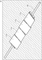
도 6a는 본 명세서에 설명된 빔-편향 수단에서 빔-편향 구역들(46) 중 하나로서 사용될 수 있는 빔-편향 엘리먼트(172)의 개략적인 측단면도를 도시한다. 빔-편향 엘리먼트(172)는 광학 채널들(16a 내지 16d) 중 하나, 복수의 광학 채널들 또는 모든 광학 채널들에 대해 동작가능할 수 있고, 트래버스형(traverse-type) 단면을 포함할 수 있다. 삼각형 단면이 도시되지만, 임의의 다른 다각형이 또한 가능하다. 대안적으로 또는 부가적으로, 단면은 또한 적어도 하나 만곡 표면을 포함할 수 있으며, 여기서 특히 반사 표면들에 관해, 적어도 구역들에서 평면인 구현이 이미징 수차들을 방지하기 위해 유리할 수 있다. 2개의 주요 측부들(174a 및 174b)은 각도 σ만큼 서로를 향해 경사져 있을 수 있다. 각도 σ는 1° 내지 89°의 값을 포함하고, 바람직하게는 5° 내지 60°의 값을 포함하며, 특히 바람직하게는 10° 내지 30°의 값을 포함할 수 있다. 바람직하게, 주요 측부들(174a 및 174b)은 최대 60°의 각도로 서로를 향해 경사져 있다.6A shows a schematic side cross-sectional view of a beam-deflecting
예를 들어, 빔-편향 엘리먼트(172)는 제1 측부(174a), 제2 측부(174b) 및 제3 측부(174c)를 포함한다. 적어도 2개의 측부들, 예를 들어 측부들(174a 및 174b)이 반사형이도록 구성되므로, 빔-편향 엘리먼트(172)이 양 측부들 상에서 반사형이도록 구성된다. 측부들(174a 및 174b)은 빔-편향 엘리먼트(172)의 주요 측부들, 즉 측부(174c)의 표면보다 큰 표면을 갖는 측부들일 수 있다.For example, the beam-deflecting
다시 말하면, 빔-편향 엘리먼트(172)는 쐐기형이고 양 측부들 상에서 반사형이도록 형성될 수 있다. 그러나, 표면(174c)과 반대로, 즉 표면들(174a 및 174b) 사이에, 표면(174c)보다 실질적으로 작은 추가적인 표면이 배열될 수 있다. 다시 말하면, 표면들(174a, 174b 및 174c)에 의해 형성된 쐐기는 임의적으로 테이퍼링(taper)되지 않지만, 그의 포인팅된 측부에 표면을 제공받으며, 그에 따라 뭉툭해진다(blunt).In other words, the beam-deflecting
도 6b는 빔-편향 엘리먼트(172)의 개략적인 측단면도를 도시하며, 여기서 빔-편향 엘리먼트(172)의 서스펜션(suspension) 또는 변위 축(176)이 설명된다. 예를 들어, 변위 축(176)은 회전 축(44)일 수 있다. 빔-편향 엘리먼트(172)가 빔-편향 수단(18)에서 회전가능하게 또는 병진적으로 이동가능할 수 있는 변위 축(176)은 단면의 중심(178)에 관해 편심적으로 변위될 수 있다. 대안적으로, 중심은 또한, 두께 방향(182)을 따른 그리고 그에 수직인 방향(184)을 따른 빔-편향 엘리먼트(172)의 치수의 절반을 설명하는 포인트일 수 있다.6B shows a schematic side cross-sectional view of the beam-deflecting
주요 측부(174a)는 표면 법선(175a)을 포함할 수 있지만, 주요 측부(174b)는 표면 법선(175b)을 포함할 수 있다. 변위 축(176)을 중심으로 한 회전 움직임이 빔-편향 수단의 제1 위치와 제2 위치 사이에서 스위칭하는 데 사용되면, 빔-편향 수단의 회전 움직임은 도 5와 조합하여 설명된 바와 같이, 주요 측부들(174a 또는 174b) 중 하나가 어레이(14)를 전적으로 향하는 2개의 위치들 사이의 배향을 빔-편향 수단이 회피하도록 실행될 수 있다. 이것은 또한, 회전 움직임에 의해 제1 및 제2 동작 상태 또는 위치 사이에서 스위칭할 경우, 제2 주요 측부의 표면 법선(175a) 및 표면 법선(175b)이 각각의 시점에서 이미지 센서를 향하는 방향에 대해 적어도 10°의 각도 및 적용가능하다면 이미지 센서의 표면 법선에 평행한 각도를 포함하도록 이해될 수 있다. 이러한 방식으로, 각도들 중 하나가 0° 또는 180°인 것이 회피될 수 있으며, 이는 두께 방향을 따른 빔-편향 수단의 큰 또는 대략 최대 확장을 표시할 수 있다.The
예를 들어, 변위 축(176)은 두께 방향(182)을 따라 변화되지 않을 수 있고, 그 방향에 수직인 방향에서 임의의 오프셋을 포함할 수 있다. 대안적으로, 두께 방향(182)을 따른 오프셋이 또한 이해가능하다. 예를 들어, 변위는, 변위 축(176)을 중심으로 한 빔-편향 엘리먼트(172)의 회전 시에, 중심(178)을 중심으로 회전할 경우와 같이 더 큰 액추에이터 이동이 획득되도록 수행될 수 있다. 따라서, 변위 축(176)의 변위에 의해, 측부들(174a 및 174b) 사이의 에지가 회전 시에 이동되는 거리는 중심(178)을 중심으로 한 회전과 비교하여 동일한 회전 각도로 증가할 수 있다. 바람직하게, 빔-편향 엘리먼트(172)는 측부들(174a 및 174b) 사이의 에지, 즉 쐐기형 단면의 포인팅된 측부가 이미지 센서를 향하도록 배열된다. 작은 회전 움직임들에 의해, 각각 다른 측부(174a 또는 174b)는 광학 채널들의 광학 경로를 편향시킬 수 있다. 주요 측부가 이미지 센서에 수직이도록 하는 그러한 방식으로의 빔-편향 엘리먼트(172)의 움직임이 요구되지 않으므로, 두께 방향(182)을 따른 빔-편향 수단의 공간 요건이 낮도록 회전이 실행될 수 있다는 것이 자명하다.For example, the
측부(174c)는 또한 보조 측부 또는 후방 측부로 지칭될 수 있다. 연결 엘리먼트가 측부(174c)에 배열되거나 또는 빔-편향 엘리먼트들의 단면을 통해 연장되도록, 즉 그것이 빔-편향 엘리먼트들 상에, 예를 들어 변위 축(176)의 구역에 배열되도록 수 개의 빔-편향 엘리먼트들이 서로 연결될 수 있다. 특히, 홀딩 엘리먼트는 그것이 방향(182)을 따라 빔-편향 엘리먼트(172)를 넘어 돌출하지 않거나 또는 오직 작은 정도로만, 즉 최대 50°, 최대 30°, 또는 최대 10°로 돌출하도록 배열될 수 있으므로, 홀딩 엘리먼트는 방향(182)을 따른 전체 구조의 확장을 증가시키지 않거나 결정하지 않는다. 대안적으로, 두께 방향(182)에서의 확장은 광학 채널들의 렌즈들에 의해 결정될 수 있고, 즉 그들은 최소 두께를 정의하는 치수를 포함한다.The
빔-편향 엘리먼트(172)는 유리, 세라믹들, 유리 세라믹들, 플라스틱들, 금속, 또는 이들 재료들 및/또는 추가적인 재료들의 임의의 조합으로 형성될 수 있다.The beam-deflecting
다시 말하면, 빔-편향 엘리먼트(172)는, 선단, 즉 주요 측부들(174a 및 174b) 사이의 에지가 이미지 센서를 향해 지향되도록 배열될 수 있다. 빔-편향 엘리먼트들을 홀딩하는 것은, 그것이 빔-편향 엘리먼트들의 내부에서 또는 후방 측부에서만 발생하도록, 즉 주요 측부들이 덮이지 않도록 수행될 수 있다. 상호 홀딩 또는 연결 엘리먼트는 후방 측부(174c)에 걸쳐 연장될 수 있다. 빔-편향 엘리먼트(172)의 회전 축은 편심적으로 배열될 수 있다.In other words, the beam-deflecting
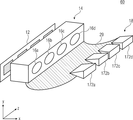
도 6c는 이미지 센서(12) 및 나란히 배열된 광학 채널들(16a 내지 16d)의 단일-라인 어레이(14)를 포함하는 다중-조리개 이미징 디바이스(60)의 개략적인 사시도를 도시한다. 빔-편향 수단(18)은 다수의 광학 채널들에 대응할 수 있는 다수의 빔-편향 엘리먼트들(172a 내지 172d)을 포함한다. 대안적으로, 예를 들어 적어도 하나의 빔-편향 엘리먼트가 2개의 광학 채널들에 의해 사용되면, 더 적은 수의 빔-편향 엘리먼트들이 배열될 수 있다. 대안적으로, 예를 들어 빔-편향 수단(18)의 편향 방향을 스위칭하는 것이 병진이동 움직임에 의해 실행되면, 더 많은 수가 또한 배열될 수 있다. 각각의 빔-편향 엘리먼트(172a 내지 172d)가 광학 채널(16a 내지 16d)에 할당될 수 있다. 빔-편향 엘리먼트(172a 내지 172d)는 다수의 엘리먼트들(172)로서 형성될 수 있다. 대안적으로, 빔-편향 엘리먼트들(172a 내지 172d) 중 적어도 2개, 수 개 또는 모두는 서로 일체로 형성될 수 있다.6C shows a schematic perspective view of a
도 6d는 빔-편향 엘리먼트(172)의 개략적인 측단면도를 도시하며, 그의 단면은 자유형(free-form) 표면으로서 형성되고, 이는 그것이 단순한 삼각형 또는 정사각형에 대응할 필요가 없다는 것을 의미한다. 따라서, 측부(174c)는 홀딩 엘리먼트를 고정시키는 것을 가능하게 하는 리세스(186)를 포함할 수 있으며, 여기서 리세스(186)는 또한 돌출 엘리먼트로서, 예를 들어 설부-홈(tongue-groove) 시스템의 홈으로서 형성될 수 있다. 단면은, 주요 측부들(174a 및 174b)보다 작은 표면 확장을 갖고 그 주요 측부들을 서로 연결시키는 제4 측부(174d)를 더 포함한다.6D shows a schematic side cross-sectional view of the beam-deflecting
도 6e는 제1 빔-편향 엘리먼트(172a) 및 그 엘리먼트 뒤에 예시 방향으로 배열된 제2 빔-편향 엘리먼트(172b)의 개략적인 측단면도를 도시한다. 이러한 경우, 리세스들(186a 및 186b)은, 그들이 실질적으로 일치하도록 배열될 수 있으므로, 리세스들 내의 연결 엘리먼트의 배열이 가능하다.6E shows a schematic side cross-sectional view of a first beam-deflecting
도 6f는, 예를 들어 연결 엘리먼트(188)와 연결된 4개의 빔-편향 엘리먼트들(172a 내지 172d)을 포함하는 빔-편향 수단(18)의 개략적인 사시도를 도시한다. 연결 엘리먼트는 액추에이터 방식에 의해 병진적으로 그리고/또는 회전가능하게 이동되도록 사용가능할 수 있다. 연결 엘리먼트(188)는 일체로 구성될 수 있으며, 빔-편향 엘리먼트들(172a 내지 172d)에서 또는 그 내에서 연장 방향, 예를 들어 y 방향에 걸쳐 연장될 수 있다. 대안적으로, 연결 엘리먼트(188)는 또한, 예를 들어 빔-편향 엘리먼트들(172a 내지 172d)이 일체로 형성되면, 빔-편향 수단(18)의 적어도 하나의 측부에만 연결될 수 있다. 대안적으로, 액추에이터에 대한 연결 및/또는 빔-편향 엘리먼트들(172a 내지 172d)의 연결은 또한, 임의의 다른 방식으로, 예를 들어 접착, 접합 또는 납땜에 의해 수행될 수 있다. 빔-편향 엘리먼트들(172a 내지 172d)은 서로 작은 거리로 또는 심지어 서로 직접 접촉하여 형성될 수 있으므로, 빔-편향 엘리먼트들(172a 내지 172d) 사이에 구현되는 어떠한 갭들도 존재하지 않거나 가능한 적은 갭들이 존재한다.6F shows a schematic perspective view of a beam-deflecting means 18 comprising for example four beam-deflecting
이것은, 빔-편향 수단(18)이 인접하게 배열된 패시트들의 어레이로서 형성될 수 있으며, 각각의 광학 채널이 패시트들 중 하나에 할당된다는 것을 의미한다. 다이어프램 구조는 패시트들의 어레이에 걸쳐 연장될 수 있다.This means that the beam-deflecting means 18 can be formed as an array of facets arranged adjacently, each optical channel being assigned to one of the facets. The diaphragm structure can extend over the array of facets.
빔-편향 수단은 제1 및 제2 반사 주요 측부(174a 및 174b)를 포함할 수 있으며, 여기서 주요 측부들은 60° 또는 그 미만의 각도 δ로 서로를 향해 경사져 있을 수 있다.The beam-deflecting means can include first and second reflective
도 7a 내지 도 7c에 기초하여, 도 6a 내지 도 4f에 따른 쐐기형 패시트들을 포함하는 회전가능하게 이동가능한 빔-편향 수단(18)을 포함하는 다중-조리개 이미징 디바이스(70)가 후속하여 설명된다. 어레이(14)의 광학기기들(64)은 다중-부분 렌즈 조합들로서 예시적으로 형성된다. 예를 들어, 다중-조리개 이미징 디바이스(70)는 주요 측부들(174a 및 174b) 사이의 연결 에지에서 또는 보조 측부(174d)에서 기계식으로 고정될 수 있는 다이어프램 구조(22)를 포함한다. 광학기기들(64)은 하우징(21)에 배열될 수 있다. 선택적으로, 이미지 센서(12)가 또한 하우징(21)에 배열될 수 있다. 후속 논의들이 광학기기들(64)이 배열되는 하우징에 관한 것이지만, 동일한 논의들은 또한, 캐리어(47)에 대해 설명된 바와 같이, 예를 들어 캐리어를 포함하는 광학 채널들의 어레이에 제한들 없이 적용된다. 광학기기들(64)은 가급적 투명 방식으로 형성되는 캐리어(47)에서 직접적으로 또는 홀딩 구조들을 통해 간접적으로 배열될 수 있다. 예를 들어, 하우징(21)은 주요 측부들(211 및 212)을 포함할 수 있으며, 여기서 주요 측부(211)는, 그것이 빔-편향 수단(18)을 향하도록 배열되고 빔-편향 수단(18)에 인접한 하우징(21)의 측부를 제공하는 것을 특징으로 한다. 예를 들어, 도 1을 고려할 경우, 캐리어(47)는 또한, 빔-편향 수단(18)을 향하도록 배열된 주요 측부 및 이미지 센서(12)를 향하도록 배열된 주요 측부를 포함할 수 있다. 보조 측부들(213 및 214)은 2개의 주요 측부들(211 및 212)을 서로 연결시킬 수 있다. 하우징(21)의 적어도 주요 측부(211)는 또한 어레이의 주요 측부인 것으로 이해될 수 있다.Based on FIGS. 7A-7C, a
도 7a는 빔-편향 수단(18)의 제1 위치를 갖는 다중-조리개 이미징 디바이스(70)를 이제 예시하며, 여기서 다이어프램 구조(22)는 슬릿(291)을 폐쇄한다.Figure 7a is a beam of
도 7b는 빔-편향 수단(18)의 제2 위치에 있는 다중-조리개 이미징 디바이스(70)를 예시하며, 여기서 다이어프램 구조(22)는 슬릿(292)을 폐쇄한다. 도 7a에 예시된 제1 위치에서, 다이어프램 구조는 가능한 한 외측 측부 상에서 기계식으로 접촉할 수 있으며, 이는 보조 측부(214)에 인접하다는 것을 의미하고, 이는 보조 측부(214)에 인접한 주요 측부(211) 또는 도 1에 예시적으로 예시된 바와 같이 보조 측부(214)를 의미한다. 도 7b는, 다이어프램 구조(22)가 보조 측부(213)에 인접하게 하우징(21) 또는 어레이와 기계식으로 접촉하는 상황을 예시한다.Figure 7b is a beam-multiple in the second position of the deflection means (18), illustrate
도 7c는 제1 위치와 제2 위치 사이의 선택적인 중간 위치에 있는 다중-조리개 이미징 디바이스(70)를 예시한다. 이러한 제3 위치에서, 다이어프램 구조(22)는 보조 측부들(213 및 214) 사이의 구역을 향해 지향된다. 도 7a 및 도 7b에 따른 예시에 기초하여, 다이어프램 구조(22)는 탄성적으로 또는 가요성으로 형성될 수 있으며, 예를 들어 가요성 다이어프램 또는 밀봉 립을 제공할 수 있다. 이를 위해, 다이어프램 구조(22)는 실리콘, 폴리우레탄 또는 다른 탄성중합체들과 같은 탄성 재료들을 포함할 수 있다. 제1 위치와 제2 위치 사이에서 스위칭할 경우, 다이어프램 구조(22)는 주요 측부(211)에 걸쳐 브러싱(brush)할 수 있다. 그러나, 도 7c에 예시된 바와 같이, 빔-편향 수단(18)과 어레이(14) 또는 하우징(21) 사이의 가변 거리에 기초하여, 다이어프램 구조(22)가 어레이(14) 또는 하우징(21)에 대한 접촉이 없는 상황이 획득될 수 있다. 이를 위해, 다중-조리개 이미징 디바이스(70)는, 예를 들어 어레이와 빔-편향 수단(18) 사이의 거리를 일시적으로 증가시키기 위해 빔-편향 수단(18) 및/또는 어레이(14)를 병진적으로 이동시키도록 구성되는 액추에이터를 포함할 수 있다. 이것은, 다중-조리개 이미징 디바이스(70)가 어레이와 다이어프램 구조 사이의 거리를 일시적으로 증가시키기 위해 빔-편향 수단의 회전 움직임 동안 어레이(14)와 다이어프램 구조(22) 사이에 병진이동 움직임을 제공하도록 구성될 수 있다는 것을 의미한다.7C illustrates the
다시 말하면, 바람직하게는 가요성 재료로부터 제조되고, 미러의 모든 패시트들에 걸쳐 그리고 그에 따라 어레이 대물렌즈의 전체 폭에 걸쳐 연장되는 다이어프램은 선형 채널 배열을 갖는 다중-조리개 이미징 디바이스의 빔-편향 수단의 측부/에지에 배열된다. 다이어프램은 밀봉 립과 유사하다. 2개의 사용 상태들, 즉 제1 및 제2 위치들에서, 가요성 다이어프램은 어레이 대물렌즈 위 또는 아래 중 어느 하나에 배열되고, 어레이 대물렌즈와 빔-편향 수단 사이의 갭을 폐쇄하여, 미광이 카메라에 진입할 수 없게 하거나 단지 제한된 정도만 진입할 수 있게 한다. 카메라가 사용되지 않고 빔-편향 수단이 중간 위치에 머무르는 제3 상태에서, 가요성 다이어프램은 어레이 대물렌즈 위 또는 아래 중 어느 곳에도 위치되지 않을 수 있다.In other words, the diaphragm is preferably made from a flexible material and extends across all facets of the mirror and thus across the entire width of the array objective, beam-deflection of a multi-aperture imaging device with a linear channel arrangement. It is arranged on the side / edge of the means. The diaphragm is similar to a sealing lip. In two use states, i.e. first and second positions, the flexible diaphragm is arranged either above or below the array objective, closing the gap between the array objective and the beam-deflecting means, stray light It makes it impossible to enter the camera or only a limited amount. In a third state in which the camera is not used and the beam-deflecting means stays in the intermediate position, the flexible diaphragm may not be positioned above or below the array objective.
도 8은 일 실시예에 따른 다중-조리개 이미징 디바이스(80)의 개략적인 측단면도를 도시한다. 다중-조리개 이미징 디바이스(70)와 비교하여, 다중-조리개 이미징 디바이스(80)는 어레이(14) 또는 하우징(21) 및/또는 빔-편향 수단(18)에 힘을 인가하도록 구성된 광학 이미지 안정화기(34)를 포함한다. 생성된 힘으로 인해, 예를 들어 이미지 센서(12)에 의해 제공되는 이미지의 이미지 축들 중 하나 또는 둘 모두를 따른 어레이(14)의 병진이동 변위에 의해 이미지 센서(12), 어레이(14) 및 빔-편향 수단(18) 사이의 상대적인 움직임이 획득될 수 있다. 예를 들어, 이것을 위해 제공된 것은 라인-연장 방향에 평행한 z-방향을 따른 또는 이미지 축들(36 및/또는 38)에 평행하게 배열될 수 있거나 이러한 방향으로 적어도 부분적으로 연장될 수 있는 y-방향에 따른 움직임일 수 있으며, 이는 그들이 대응하는 방향 컴포넌트를 포함한다는 것을 의미한다. 예를 들어, 대안적으로 또는 부가적으로, 예를 들어 y-방향을 따른 빔-편향 수단(18)의 병진이동의 상대적인 움직임 및/또는 축(176)을 중심으로 한 회전 움직임은 y-방향에 평행하게 배열된 이미지 방향(36 또는 38)을 따라 광학 이미지 안정화를 획득하도록 생성될 수 있다. 이것은, 이러한 경우, 어레이(14)가 하나의 방향, 예를 들어 z를 따라서만 이동될 수 있고 이미지 안정화가 빔-편향 수단의 움직임과 함께 2개의 방향들을 따라 획득될 수 있으며, 방향들을 스위칭하기 위한 빔-편향 수단의 움직임 자유도가 이미 제공될 수 있으므로, 낮은 복잡도를 가능하게 한다. 어레이(14)의 움직임에 대안적으로 또는 부가적으로, 이미지 센서(12)의 움직임이 또한, 광학 이미지 안정화를 완전히 또는 부분적으로 구현하기 위해 제공될 수 있다. 부분 시야들 또는 전체 시야가 캡처되고 있는 캡처 프로세스에서, 그의 시야가 캡처되고 있는 다중-조리개 이미징 디바이스(60)가 물체 구역에 관해 이동되면, 광학 이미지 안정화가 유리할 수 있다. 예를 들어, 이미지 안정화를 위한 회전 움직임은 회전 움직임(38)과 중첩될 수 있고, 동일한 액추에이터에 의해 제공될 수 있다.8 shows a schematic side cross-sectional view of a
광학 이미지 안정화기(34)는 이미지의 흔들림을 감소시키거나 방지하기 위해 이러한 움직임에 적어도 부분적으로 대처하도록 구성될 수 있다. 예를 들어, 라인-연장 방향 z에 평행하게 배열될 수 있는 제1 이미지 축(36)을 따른 광학 이미지 안정화를 위해, 광학 이미지 안정화기(34)는 이미지 센서(12), 어레이(14) 및 빔-편향 수단(18) 사이에서 제1 상대적인 움직임을 생성하도록 구성될 수 있다. 이에 수직으로 배열된 제2 이미지 축(39)을 따른 광학 이미지 안정화를 위해, 광학 이미지 안정화기(34)는 이미지 센서(12), 어레이(14) 및 빔-편향 수단(18) 사이에서 제2 상대적인 움직임을 생성하도록 구성될 수 있다. 제1 상대적인 움직임을 위해, 광학 이미지 안정화기(34)는 이미지 축(36)을 따라 어레이(14) 또는 이미지 센서(12)를 병진적으로 시프트시키도록 구성될 수 있다. 대안적으로 또는 부가적으로, 광학 이미지 안정화기(34)는 이미지 축(36)을 따라 빔-편향 수단(18)의 병진이동 움직임을 생성하도록 구성될 수 있다. 이러한 경우, 광학 이미지 안정화기(34)는 컴포넌트들의 움직임들을 실행하여, 대응하는 상대적인 움직임이 이미지 센서(12), 어레이(14) 및 빔-편향 수단(18) 사이에서 생성되도록 이루어진다. 상대적인 움직임은 라인-연장 방향 z에 평행하고 광학 경로들에 수직으로 수행될 수 있다. 그러나, 예를 들어, 추가적인 컴포넌트들에 관해 이미지 센서(12)의 전자 회로부에 가능한 적게 기계식으로 스트레스를 주거나 또는 전혀 스트레스트를 주지 않기 위해 이미지 센서(12)에 관해 어레이(14)를 병진이동시키는 것이 유리할 수 있다.The
제2 상대적인 움직임을 생성하기 위해, 광학 이미지 안정화기(34)는 빔-편향 수단(18)의 회전 움직임을 생성하거나 회전 움직임을 가능하게 하도록 구성될 수 있다. 그 움직임은 빔-편향 수단(18)을 회전가능하게 스위칭하기 위한 움직임과 중첩될 수 있다. 회전 움직임들 둘 모두에 대해 개별 액추에이터들 또는 조합된 액추에이터 수단이 제공될 수 있다. 대안적으로 또는 부가적으로, 광학 이미지 안정화기는 이미지 축(39)을 따라 이미지 센서(12)와 어레이(14) 사이에 병진이동의 상대적인 움직임을 제공하고 그리고/또는 어레이(14)와 빔-편향 수단(18) 사이에 병진이동의 상대적인 움직임을 제공하도록 구성될 수 있으며, 여기서 대응하는 액추에이터들이 이를 위해 배열될 수 있다. 예를 들어, 회전 움직임(38)과 평행하게 또는 그의 일부로서 회전 움직임을 생성하기 위해, 광학 이미지 안정화기(34)는, 예를 들어 회전 움직임(38)을 생성하도록 구성된 액추에이터를 포함할 수 있다. 광학 이미지 안정화기(34)가 병진이동의 상대적인 움직임들로서 제1 및 제2 상대적인 움직임들을 제어하도록 광학 이미지 안정화기를 구현하는 것이 이미지 안정화를 획득하기 위해 가능하지만, 제2 이미지 축(39)을 따른 컴포넌트들의 병진이동 움직임이 이러한 경우 회피될 수 있으므로, 회전 움직임(38)으로서의 제2 상대적인 움직임의 구현이 유리할 수 있다. 이러한 방향은, 일부 실시예들에 따르면 가능한 낮게 유지될 다중-조리개 이미징 디바이스(60)의 두께 방향에 평행할 수 있다. 그러한 목적은 회전 움직임에 의해 달성될 수 있다.To generate the second relative motion, the
광학 이미지 안정화기(34)에 의해 트리거링될 수 있는 z-방향을 따른 어레이(14)의 병진이동 움직임 및/또는 회전 움직임(38) 및 도 8을 고려할 경우, 다이어프램 구조(22)의 변형이 상대적인 움직임에 기초하여 발생하므로, 개개의 상대적인 움직임이 광학 이미지 안정화기(34)에 의해 생성되면, 다이어프램 구조(22)의 탄성 또는 다이어프램 구조의 강성(rigidity) 뿐만 아니라, 다이어프램 구조(22)와 어레이(14) 또는 빔-편향 수단(18) 사이의 기계식 접촉에 기초하여 복원력이 획득될 수 있다. 대안적으로 또는 부가적으로, 그러한 복원력은 별개의 스프링 구조들, 예를 들어 탄성 연결 엘리먼트들에 의해 적어도 부분적으로 획득될 수 있다. 복원력은 광학 이미지 안정화기(34)의 힘이 취소되면, 최대 상대적인 움직임, 즉 광학 이미지 안정화기(34)에 의한 상대적인 움직임과 관련된 최대 편향의 적어도 30%, 적어도 20%, 또는 적어도 10%를 복원하도록 구성될 수 있다.Considering the translational and / or
다시 말하면, 예를 들어, 가요성 다이어프램(22) 그 자체, 또는 도입 또는 부착되는 부가적인 엘리먼트들은 빔-편향 수단에 대한 스프링 엘리먼트들로서 기능할 수 있으며, 따라서 광학 이미지 안정화를 위해 그 엘리먼트들을 사용할 경우 복원 효과를 가질 수 있다.In other words, for example, the
광학 이미지 안정화기가 가요성 다이어프램과 조합하여 설명되지만, 광학 이미지 안정화기는 또한, 예를 들어 다중-조리개 이미징 디바이스(10)에서 가요성 다이어프램 없이 배열될 수 있다.Although the optical image stabilizer is described in combination with a flexible diaphragm, the optical image stabilizer can also be arranged without a flexible diaphragm in the
도 9는, 빔-편향 수단(18)으로부터 시작하여 뷰잉 방향들(271 및 272)을 따라 배열된 투명 구조들(37a 및 37b)을 포함하는, 일 실시예에 따른 다중-조리개 이미징 디바이스(90)의 개략적인 사시도를 도시한다. 투명 구조들(37a 및 37b)은 하우징(21), 빔-편향 수단(18) 또는 추가적인 컴포넌트들의 방향으로 먼지 또는 입자들의 진입을 방지하도록 구성될 수 있다. 대안적으로 또는 부가적으로, 예를 들어 사용자의 손가락 등에 의해 빔-편향 수단(18)을 터치하는 것이 방지되거나 더 어려워지게 될 수 있다. 예를 들어, 다중-조리개 이미징 디바이스(90)는 2개의 뷰잉 방향들 및 2개의 투명 구조들(37a 및 37b)을 포함하며, 여기서 투명 구조들(37a 및 37b) 각각은 뷰잉 방향들(271 및 272) 중 하나와 각각 연관될 수 있다. 예를 들어, 하나의 뷰잉 방향만을 포함하도록 형성될 수 있는 다중-조리개 이미징 디바이스(10)를 고려할 경우, 다중-조리개 이미징 디바이스는 또한 하나의 투명 구조(37)만을 이용하여 구현될 수 있다.9 is beam-aperture imaging device, starting from the deflection means 18, the viewing direction (27 1 and 27 2) multiple in accordance with one embodiment, including the transparent structures (37a and 37b) arranged along the A schematic perspective view of 90 is shown. The
예를 들어, 투명 구조들(37a)은 유리 재료 및/또는 중합체 재료를 포함할 수 있고, 전자기 방사가 다중-조리개 이미징 디바이스(90)에 의해 캡처되기 위해 본질적으로 투명이도록 형성될 수 있으며, 필터들이 투명 구조들로 도입되는 것이 또한 이해가능하다. 투명 구조들(37a 및/또는 37b)은 낮은 표면 조도(roughness)를 포함할 수 있으며, 이는 투명 구조들(37a 및/또는 37b)이 매끄럽도록 구현될 수 있다는 것을 의미한다.For example, the
그러나, 제한으로 구성되지 않는 투명 구조들(37a 및/또는 37b)에 대한 조도 Ra의 예시적인 값은, 예를 들어 최대 0.03μm, 최대 0.005μm, 또는 최대 0.0005μm일 수 있다. 다이어프램 구조(22)는 조도를 포함할 수 있으며, 그의 조도 값은 투명 구조들(37a 및/또는 37b)의 조도보다 상당히 더 크다. 이것은, 투명 구조(37a 및/또는 37b)에서의 다이어프램 구조(22)의 접착을 더 어렵게 하거나 둘 사이의 기계식 접촉 시에 접착을 회피하는 것을 가능하게 한다. 이것은, 어레이(14)와의 기계식 접촉에 대안적으로, 다이어프램 구조(22)가, 예를 들어 일시적으로 교번하는 방식으로 투명 구조(37a 및/또는 37b)와 기계식으로 접촉할 수 있다는 것을 의미한다. 제1 위치에서 그리고 제2 위치에서, 다이어프램 구조는 한편으로는 어레이(14), 또는 투명 구조들(37a 및 37b) 중 하나와 그리고 다른 한편으로는 빔-편향 수단(18)과 기계식으로 접촉할 수 있다.However, exemplary values of the roughness R a for
다시 말하면, 가요성 다이어프램(22)은, 다이어프램이 커버 유리들(37a 및/또는 37b)과 같은 매끄러운 표면들에 접착되지 않을 수 있고 그리고/또는 빔-편향 수단에 의해 인가되는 작은 힘들이 있을 시에 표면으로부터 해제될 수 있도록 거친 표면을 포함할 수 있다. 이것은, 접착성이 존재하더라도, 다이어프램 구조(22)가 회전 움직임으로 인해 투명 구조들(37a 및/또는 37b)로부터 용이하게 해제될 수 있다는 것을 의미한다.In other words, the
도 10은 선택적으로 투명 구조들(37a 및/또는 37b)을 포함할 수 있지만 투명 구조들 없이도 용이하게 구현가능한 다중-조리개 이미징 디바이스(100)의 개략적인 측단면도를 도시한다. 다중-조리개 이미징 디바이스(100)는, 다이어프램 구조(22)와 유사한 방식으로 형성될 수 있지만; 자기 또는 자화가능 재료, 예를 들어 강자성 또는 상자성 재료들을 부가적으로 포함할 수 있는 다이어프램 구조(22')를 포함한다. 예를 들어, 이들 재료들은 다이어프램 구조(22)의 재료들 내로 입자들, 칩들, 쏘잉(sawing)들, 또는 그라인딩(grinding)들로서 도입될 수 있다. 이것은 다이어프램 구조(22')가 자기 재료들을 포함할 수 있다는 것을 의미한다. 자기장-제공 엘리먼트(44a 및/또는 44b), 즉 자기장 소스는 하우징(21) 및/또는 투명 구조들(37a 및/또는 37b)에 인접하게 그리고 그에 따라 다이어프램 구조(22)에 인접하게 배열될 수 있다. 바람직하게, 자기장-제공 엘리먼트들(44a 및/또는 44b)은, 바람직하게는 강하거나 바람직하게는 약한 자기장을 일시적으로 교번으로 제공하거나 어떠한 것도 전혀 제공하지 않는 엘리먼트들일 수 있다. 예를 들어, 자기장 소스들(44a 및 44b)은 전자석들일 수 있다. 대안적으로 또는 부가적으로, 자기장 소스들은, 예를 들어 영구 자석들을 포함하며, 작은 거리에서 상당히 큰 자기장을 제공하고 큰 거리에서 상당히 작은 자기장을 제공하기 위해 다이어프램 구조(22')에 대해 가변 거리로 배열되는 것이 또한 이해가능하다.10 shows a schematic cross-sectional side view of a
자기장 소스들(44a 및 44b)의 자기장들은, 인력이 자기장에 기초하여 다이어프램 구조(22')에 인가되어, 인력이 빔-편향 수단(18)의 회전 움직임을 실행하거나 적어도 빔-편향 수단을 지지하도록 구성될 수 있다. 대안적으로 또는 부가적으로, 빔-편향 수단(18)의 회전 움직임 이후, 어레이(14)의 시야에서 가급적 유지되는 다이어프램 구조(22')의 일부가 이러한 시야 밖으로 이동되는, 즉 인력에 의해 끌어당겨지는 것이 또한 이해가능하다.The magnetic fields of the
다시 말하면, 빔-편향 수단(18)의 회전 움직임에 부가하여 가요성 다이어프램을 끌어당기는 전자석들은 코일 및 적용가능하다면 부가적인 코어로부터 어레이 대물렌즈 위 및 아래에 형성될 수 있으므로, 다이어프램은 훨씬 더 개선된 광-밀봉 효과를 갖는다.In other words, the electromagnets that attract the flexible diaphragm in addition to the rotational movement of the beam-deflecting means 18 can be formed above and below the array objective from the coil and, if applicable, additional cores, the diaphragm is much improved. Has a light-sealing effect.
다이어프램 구조의 위에서-설명된 배열은 다중-조리개 이미징 디바이스들에서 미광 억제의 개선을 가능하게 한다. 그러한 다중-조리개 이미징 디바이스들 및/또는 다중-조리개 이미징 시스템들은 선형 채널 배열 및 가장 작은 설치 사이즈를 갖는 개념들에서 사용될 수 있다.The above-described arrangement of the diaphragm structure enables improvement of stray light suppression in multi-aperture imaging devices. Such multi-aperture imaging devices and / or multi-aperture imaging systems can be used in concepts with a linear channel arrangement and the smallest installation size.
실시예들에 따르면, 2개 또는 수 개 또는 가급적 모든 광학 채널들에 대해 채널-개별적인 방식으로, 다중-조리개 이미징 디바이스(100)의 포커스 또는 본 명세서에 설명된 다중-조리개 이미징 디바이스들, 예를 들어 다중-조리개 이미징 디바이스(10, 10', 40, 50, 60, 70, 80, 또는 90) 중 다른 것의 포커스를 변화시키도록 구성되는 포커싱 수단이 제공될 수 있다. 이를 위해, 액추에이터가, 예를 들어 어레이(14)의 적어도 하나의 광학기기 또는 전체 어레이(14)와 이미지 센서(12) 사이의 거리를 변화시키는 데 사용될 수 있다. 이것은, 예를 들어 광학 채널의 광학기기, 즉 대물렌즈가 축방향으로 이동되면, 광학기기 또는 어레이(14)와 빔-편향 수단(18) 사이의 가변 거리를 유발할 수 있다. 가요성 또는 탄성 다이어프램에 의해, 어레이(14)와 빔-편향 수단(18) 사이의 슬릿은, 예를 들어 x-방향을 따른 다이어프램 구조(22')의 축방향 확장이 어레이(14)와 빔-편향 수단(18) 사이의 최대 거리보다 크거나 그와 동일하면 폐쇄되게 유지될 수 있다. 거리를 감소시키고 그리고/또는 후속하여 거리를 증가시킬 경우, 다이어프램 구조(22')의 선형 압축/신장(elongation) 또는 변형은 슬릿을 폐쇄되게 유지할 수 있다.According to embodiments, the focus of the
광학 이미지 안정화를 위한 수단 또는 광학 이미지 안정화기 및 포커싱 수단이 가요성 다이어프램과 관련하여 설명되지만, 둘 모두의 수단은 개별적으로 또는 조합하여 그리고 또한 그러한 다이어프램 없이 제공될 수 있다. 예를 들어, 어레이(14) 및 이미지 센서(12)는 광학 안정화기의 액추에이터에 의해, 예를 들어 이동가능한 이동 캐리지 내에서, 그 이동 캐리지에서 또는 그 상에서 상호 유닛을 배열하고 이동시킴으로써 상호 유닛으로서 이동될 수 있다. 이러한 유닛 내에서, 어레이의 하나, 수 개 또는 모든 광학기기들과 빔-편향 수단(18) 및/또는 이미지 센서(12) 사이의 움직임을 제공하기 위해 하나 또는 수 개의 액추에이터들이 제공될 수 있다. 그러한 움직임은 광학기기들 및/또는 가능한 광학기기들에 연결된 캐리어들을 이동시킴으로써 발생할 수 있다.Although means for optical image stabilization or optical image stabilizer and focusing means are described in connection with the flexible diaphragm, both means can be provided individually or in combination and also without such a diaphragm. For example, the
조정 움직임에서, 광학 이미지 안정화를 위한 수단 및/또는 포커싱 수단이 그에 따라 움직여질 수 있다. 대안적으로 또는 부가적으로, 동일한 액추에이터들 또는 액추에이팅 수단이 또한 움직임을 생성하기 위해 사용될 수 있다.In the adjustment movement, the means for stabilizing the optical image and / or the focusing means can be moved accordingly. Alternatively or additionally, the same actuators or actuating means can also be used to generate movement.
도 11은, 예를 들어 위에서-설명된 다중-조리개 이미징 디바이스, 예를 들어 다중-조리개 이미징 디바이스(10, 10', 40, 50, 60, 70, 80, 90, 또는 100)를 이용하여 검출될 수 있는 바와 같은 전체 시야(71)의 개략적인 예시를 도시한다. 위에서-설명된 다중-조리개 이미징 디바이스가 그들이 전체 시야 중 4개의 부분 시야들(72a 내지 72d)을 캡처하기 위한 4개의 광학 채널들을 예시적으로 포함하도록 설명되지만, 본 명세서에-설명된 다중-조리개 이미징 디바이스들이 또한 상이한 수의 광학 채널들, 예를 들어 적어도 2개, 적어도 3개, 적어도 4개, 적어도 10개, 적어도 20개, 또는 임의의 더 높은 값의 수로 형성될 수 있음을 유의해야 한다. 더욱이, 부분 시야들(72a 내지 72d) 중 일부가 하나 초과의 수의 광학 채널을 이용하여 캡처될 수 있다는 것이 이해가능함을 유의해야 한다. 다중-조리개 이미징 디바이스들의 광학 채널들의 광학 경로들은 상이한 부분 시야들(72a 내지 72d)로 안내될 수 있으며, 여기서 각각의 광학 채널은 부분 시야(72-d)를 할당받을 수 있다. 예를 들어, 부분 시야들(72a 내지 72d)은 개별적인 부분 시야들을 전체 시야로 결합하는 것을 가능하게 하기 위해 서로 중첩된다. 다중-조리개 이미징 디바이스가 4와 상이한 다수의 광학 채널들을 포함하면, 전체 시야(71)는 4와 상이한 다수의 부분 시야들을 포함할 수 있다. 대안적으로 또는 부가적으로, 적어도 하나의 부분 시야(72a 내지 72d)는 제2 광학 채널에 의해, 또는 스테레오 카메라들, 트리오(trio) 카메라들, 콰트로(quattro) 카메라들, 또는 더 높은 값들의 카메라들을 형성하기 위해 임의의 더 높은 수의 모듈들(다중-조리개 이미징 디바이스들)을 갖는 임의의 더 높은 수의 광학 채널들에 의해 캡처될 수 있다. 개별 모듈들은 픽셀의 일부들에 의해 시프트될 수 있고, 초-해상도의 방법들을 구현하도록 구성될 수 있다. 예를 들어, 다수의 광학 채널들 및/또는 다수의 다중-조리개 이미징 디바이스들 및/또는 다수의 부분 시야들은 임의적이다.FIG. 11 detects, for example, using the multi-aperture imaging device described above, eg, a multi-aperture imaging device (10, 10 ', 40, 50, 60, 70, 80, 90, or 100). A schematic illustration of the entire field of
도 12는 하우징(73), 및 하우징(73)에 배열된 제1 다중-조리개 이미징 디바이스(10a) 및 제2 다중-조리개 이미징 디바이스(10b)를 포함하는 이미징 시스템(120)의 개략적인 사시도를 도시한다. 이미징 시스템(120)은, 다중-조리개 이미징 디바이스들(10a 및 10b)을 이용하여 입체적인 방식으로, 예를 들어 다중-조리개 이미징 디바이스들(10a 및 10b)의 캡처 구역들 중 중첩 구역에서 적어도 부분적으로 전체 시야(71)를 캡처하도록 이루어진다. 중첩 구역은 전체 시야(71)의 일부를 형성할 수 있지만, 거의 전적으로 또는 전적으로, 즉 적어도 95%, 적어도 97%, 또는 적어도 99%의 비율로 전체 시야(71)를 덮을 수 있다. 예를 들어, 전체 시야(71)는 주요 측부(74a)로부터 멀어지는 쪽을 향하게 하우징(73)의 주요 측부(74b)에 배열된다. 예를 들어, 다중-조리개 이미징 디바이스들(10a 및 10b)은 투명 구역들(68a 및 68b)을 통해 전체 시야(71)를 각각 캡처할 수 있으며, 여기서 주요 측부(74b)에 배열되는 다이어프램들(78a 및 78c)은 적어도 부분적으로 투명할 수 있다. 주요 측부(74a)에 배열된 다이어프램들(78b 및 78d)은, 주요 측부(74a)를 향하는 측부로부터의 미광의 양(이는 다중-조리개 이미징 디바이스들(10a 및/또는 10b)의 레코딩들을 위조할 수 있음)이 적어도 감소되도록 투명 구역들(68b 및 68d)을 적어도 부분적으로 광학적으로 폐쇄하는 투명 구역들(78b 및 78d)을 각각 포함할 수 있다. 주요 측부(74a)는 장치(30)의 하우징 측부(23a)와 비슷할 수 있다. 동일한 방식으로, 주요 측부(74b)는 하우징 측부(23b)와 비슷할 수 있다. 다이어프램(68a 내지 68d)을 제공하는 것에 대한 대안으로서, 하나 또는 둘 모두의 다중-조리개 이미징 디바이스들(10a 및/또는 10b)의 빔-편향 수단 또는 상호 빔-편향 수단이 하우징(73) 밖으로 이동될 수 있다.FIG. 12 is a schematic perspective view of an
다중-조리개 이미징 디바이스들(10a 및 10b)이 서로 이격되게 배열되는 것으로 예시되지만, 다중-조리개 이미징 디바이스들(10a 및 10b)은 또한 공간적으로 이웃하도록 또는 조합된 방식으로 배열될 수 있다. 예를 들어, 이미징 디바이스들(10a 및 10b)의 어레이들은 나란히 또는 서로 평행하게 배열될 수 있다. 예를 들어, 어레이들은 다중-라인 방식으로 또는 단일-라인 방식으로 형성될 수 있고 서로를 향해 배열되는 라인들을 형성할 수 있으며, 여기서 각각의 다중-조리개 이미징 디바이스(10a 및 10b)는 단일-라인 어레이를 포함한다. 다중-조리개 이미징 디바이스들(10a 및 10b)은 상호 빔-편향 수단 및/또는 상호 캐리어(47) 및/또는 상호 이미지 센서(12)를 포함할 수 있다. 이것은, 다중-조리개 이미징 디바이스들(10a 및 10b) 및/또는 추가적인 다중-조리개 이미징 디바이스들이 상호 이미지 센서, 다중-조리개 이미징 디바이스들을 제어 및/또는 판독하기 위한 상호 전자 캐리어 및/또는 상호 빔-편향 유닛을 포함할 수 있다는 것을 의미한다. 다중-조리개 이미징 디바이스(10a 및/또는 10b)에 대안적으로 또는 부가적으로, 적어도 다중-조리개 이미징 디바이스(10', 40, 50, 60, 70, 80, 90 및/또는 100) 및/또는 추가적인 다중-조리개 이미징 디바이스(10)가 배열될 수 있다. 예를 들어, 위에서-설명된 상호 엘리먼트들, 예를 들어 빔-편향 수단(18) 또는 어레이(14)는, 빔-편향 수단의 움직임이 수 개의 모듈들의 광학 채널들에 대해 상호 작용할 수 있으므로 상호 광학 이미지 안정화기에 의해 사용될 수 있으며, 이는 상호 광학 이미지 안정화를 가능하게 한다. 따라서, 광학 이미지 안정화기는 또한 수 개의 모듈들에 대해 상호 구현될 수 있고 그리고/또는 상호 기준 채널이 수 개의 모듈들에 대해 사용될 수 있다.Although the
투명 구역들(68a 내지 68d)에는 부가적으로, 그들이 사용되지 않는 경우 광학 구조를 덮는 스위칭가능한 다이어프램(78a 내지 78d)이 장착될 수 있다. 다이어프램들(78a 내지 78d)은 기계식으로 이동되는 부분을 포함할 수 있다. 기계식으로 이동되는 부분의 움직임은, 예를 들어 다른 움직임들을 위해 제공될 수 있는 바와 같이 액추에이터를 사용하여 수행될 수 있다. 대안적으로 또는 부가적으로, 다이어프램들(78a 내지 78d)은 전기적으로 제어가능하며, 전기변색 층 또는 전기변색 층 시퀀스를 포함하고, 즉 전기변색 다이어프램으로 형성될 수 있다.The
도 13은, 예를 들어 이미징 시스템(120)에 배열될 수 있는 바와 같은 제1 다중-조리개 이미징 디바이스(10a) 및 제2 다중-조리개 이미징 디바이스(10b)를 포함하는 개략적인 구조를 도시한다. 어레이들(14a 및 14b)은 단일-라인 방식으로 형성될 수 있고 상호 라인을 형성할 수 있다. 이미지 센서들(12a 및 12b)은 상호 기판 상에 또는 상호 회로 캐리어, 이를테면 상호 회로 보드 또는 상호 플렉스(flex) 보드 상에 마킹(mark)될 수 있다. 대안적으로, 이미지 센서들(12a 및 12b)은 또한 상이한 기판들을 포함할 수 있다. 이들 대안들의 상이한 혼합들, 예를 들어 상호 이미지 센서, 상호 어레이 및/또는 상호 빔-편향 수단(18)을 포함하는 다중-조리개 이미징 디바이스들 뿐만 아니라 별개의 컴포넌트들을 포함하는 추가적인 다중-조리개 이미징 디바이스들이 또한 명백히 가능하다. 상호 이미지 센서, 상호 어레이 및/또는 상호 빔-편향 수단의 장점은, 더 적은 수의 액추에이터들을 제어함으로써 더 높은 정밀도로 개개의 컴포넌트들의 움직임이 획득될 수 있고 액추에이터들 사이의 동기화가 사용되거나 회피될 수 있다는 것이다. 더욱이, 높은 열 안정성이 획득될 수 있다. 대안적으로 또는 부가적으로, 다른 및/또는 상이한 다중-조리개 이미징 디바이스들은 상호 어레이, 상호 이미지 센서 및/또는 상호 빔-편향 수단을 포함할 수 있다.FIG. 13 shows a schematic structure comprising a first
도 14는 다중-조리개 이미징 디바이스, 예를 들어 다중-조리개 이미징 디바이스(10)를 제공하는 방법(1400)의 개략적인 흐름도를 도시한다.14 shows a schematic flow diagram of a
방법(1400)은 이미지 센서를 제공하는 단계(1410)를 포함한다. 단계(1420)는, 각각의 광학 채널이 전체 시야 중 부분 시야를 이미지 센서의 이미지 센서 구역 상으로 이미징하기 위한 광학기기를 포함하도록 광학 채널들의 어레이를 배열하는 단계를 포함한다. 단계(1430)는, 빔-편향 수단이 스위칭 움직임을 실행함으로써 제1 회전 위치와 제2 회전 위치 사이에서 스위칭가능하고, 제1 회전 위치에서는 광학 채널들의 광학 경로들을 제1 뷰잉 방향으로 편향시키고, 제2 회전 위치에서는 광학 채널들의 광학 경로들을 제2 뷰잉 방향으로 편향시키도록 구성되도록 빔-편향 수단을 배열하는 단계를 포함한다. 방법은, 어레이가 스위칭 움직임에 기초하여, 빔-편향 수단에 관한 어레이의 배향을 조정하기 위한 조정 움직임을 실행하도록 구성되도록 실행된다.
도 15는 이미지 구역을 캡처하기 위한 방법(1500)의 개략적인 흐름도를 도시한다.15 shows a schematic flow diagram of a
방법(1500)은, 광학 채널들의 어레이를 이용하여; 제1 회전 위치에서 빔-편향 수단을 이용하여 광학 채널들의 광학 경로들을 제1 뷰잉 방향으로 편향시킴으로써 제1 물체 구역을 이미징하는 단계(1510)를 포함하며, 여기서 각각의 광학 채널들은 전체 시야 중 부분 시야를 이미지 센서의 이미지 센서 구역 상으로 이미징하기 위한 광학기기를 포함한다. 단계(1520)는, 광학 채널들이 제2 뷰잉 방향으로 편향되도록 제1 회전 위치와 제2 회전 위치 사이에서 빔-편향 수단을 스위칭하기 위해 빔-편향 수단의 스위칭 움직임을 실행하는 단계를 포함한다. 단계(1530)는, 빔-편향 수단에 관한 어레이의 배향을 조정하기 위해 스위칭 움직임에 기초하여 어레이의 조정 움직임을 실행하는 단계를 포함한다.
일부 양상들이 디바이스의 맥락 내에서 설명되었더라도, 상기 양상들이 또한, 디바이스의 블록 또는 구조적인 컴포넌트가 대응하는 방법 단계 또는 방법 단계의 특징으로서 또한 이해되도록 대응하는 방법의 설명을 표현한다는 것이 이해될 것이다. 그와의 유사성에 의해, 방법 단계의 맥락 내에서 또는 방법 단계로서 설명되었던 양상들은 또한, 대응하는 디바이스의 대응하는 블록 또는 세부사항 또는 특징의 설명을 표현한다.It will be understood that although some aspects have been described within the context of a device, the above aspects also represent a description of a corresponding method such that a block or structural component of the device is also understood as a corresponding method step or characteristic of the method step. By similarity, aspects that have been described within the context of a method step or as a method step also express a description of a corresponding block or detail or feature of a corresponding device.
위에서-설명된 실시예들은 단지 본 발명의 원리들의 예시를 표현할 뿐이다. 당업자들이 본 명세서에 설명된 배열들 및 세부사항들의 수정들 및 변형들을 인식할 것이 이해된다. 이것은, 본 발명이 실시예들의 설명 및 논의에 의해 본 명세서에서 제시되었던 특정한 세부사항들보다는 다음의 청구항들의 범위에 의해서만 제한되도록 의도되기 때문이다.The above-described embodiments merely represent examples of the principles of the invention. It is understood that those skilled in the art will recognize modifications and variations of the arrangements and details described herein. This is because the present invention is intended to be limited only by the scope of the following claims rather than the specific details presented herein by the description and discussion of the embodiments.
Claims (44)
이미지 센서(12);
전체 시야(71) 중 부분 시야(72a 내지 72d)를 상기 이미지 센서(12)의 이미지 센서 구역(24a 내지 24h) 상으로 이미징하기 위한 광학기기(optic)(64a 내지 64h)를 각각 포함하는 광학 채널들(16a 내지 16h)의 어레이(14); 및
스위칭 움직임을 실행함으로써 제1 회전 위치와 제2 회전 위치 사이에서 스위칭가능하고, 상기 제1 회전 위치에서는 상기 광학 채널들(16a 내지 16h)의 광학 경로들(26a 내지 26h)을 제1 뷰잉(viewing) 방향(271)으로 편향시키고, 상기 제2 회전 위치에서는 상기 광학 채널들(16a 내지 16h)의 광학 경로들(26a 내지 26h)을 제2 뷰잉 방향(272)으로 편향시키도록 구성된 빔-편향 수단(18)을 포함하며;
상기 어레이(14)는 상기 스위칭 움직임에 기초하여, 상기 빔-편향 수단(18)에 관한 상기 어레이(14)의 배향을 조정하기 위해 조정 움직임(11)을 실행하도록 이루어지는 것을 특징으로 하는 다중-조리개 이미징 디바이스.
A multi-aperture imaging device,
An image sensor 12;
Optical channels comprising optical optics 64a to 64h, respectively, for imaging partial fields of view 72a to 72d onto the image sensor zones 24a to 24h of the image sensor 12 Array 14 of fields 16a-16h; And
A first viewing of the optical paths 26a to 26h of the optical channels 16a to 16h is switchable between the first rotational position and the second rotational position by executing the switching movement. ) beam is configured to deflect in a direction (27 1), the second rotational position in the optical channels (16a to a second viewing direction (27 2) to the optical path (26a to 26h) for 16h) and deflecting - Deflection means (18);
The array 14 is configured to perform an adjustment movement 11 to adjust the orientation of the array 14 relative to the beam-deflection means 18 based on the switching movement. Imaging device.
상기 조정 움직임(11)은 포커싱 및 광학 이미지 안정화(optical image stabilization)를 위한 움직임으로부터 상기 조정 움직임을 구별하는 것을 특징으로 하는 다중-조리개 이미징 디바이스.
According to claim 1,
The multi-aperture imaging device, characterized in that the coordinating motion (11) distinguishes the coordinating motion from motion for focusing and optical image stabilization.
상기 조정 움직임(11)은, 상기 이미지 센서(12)와 상기 어레이(14) 사이에서의 상기 광학 채널들의 연장에 평행하게 배열된 방향을 따라 상기 어레이(14)와 상기 이미지 센서(12) 사이에서 병진이동 거리를 유지하면서 발생하는 것을 특징으로 하는 다중-조리개 이미징 디바이스.
The method according to claim 1 or 2,
The adjustment movement 11 is between the array 14 and the image sensor 12 along a direction arranged parallel to the extension of the optical channels between the image sensor 12 and the array 14. A multi-aperture imaging device characterized in that it occurs while maintaining a translation distance.
상기 어레이(14)와 상기 빔-편향 수단(18) 사이의 상대적인 위치를 조정하기 위해 상기 조정 움직임(11) 동안 상기 어레이(14)를 이동시키도록 이루어지는 것을 특징으로 하는 다중-조리개 이미징 디바이스.
The method according to any one of claims 1 to 3,
Multi-aperture imaging device, characterized in that it is arranged to move the array (14) during the adjustment movement (11) to adjust the relative position between the array (14) and the beam-deflecting means (18).
상기 조정 움직임(11)에 기초하여, 상기 스위칭 움직임에 의해 요구되는 상기 빔-편향 수단(18)의 움직임 범위의 적어도 일부는 이동가능하지 않은 어레이와 비교하여 감소되는 것을 특징으로 하는 다중-조리개 이미징 디바이스.
The method according to any one of claims 1 to 4,
Based on the adjustment motion 11, at least a part of the range of motion of the beam-deflecting means 18 required by the switching motion is reduced compared to the non-movable array. device.
상기 제1 회전 위치 및 상기 제2 회전 위치에서, 상기 다중-조리개 이미징 디바이스의 두께 방향(y)을 따른 상기 빔-편향 수단의 측방향(lateral) 위치는 적어도 20%의 정도로 동일하며,
상기 측방향 위치는 상기 이미지 센서와 상기 어레이 사이의 축 방향(x)에 수직하고 라인-연장 방향(z)에 수직하게 배열되는 것을 특징으로 하는 다중-조리개 이미징 디바이스.
The method according to any one of claims 1 to 5,
In the first rotational position and the second rotational position, the lateral position of the beam-deflecting means along the thickness direction y of the multi-aperture imaging device is the same as at least 20%,
Wherein the lateral position is perpendicular to the axial direction (x) between the image sensor and the array and perpendicular to the line-extension direction (z).
상기 스위칭 움직임은 상기 빔-편향 수단(18)의 회전 움직임(38)을 포함하며,
상기 조정 움직임(11)은 라인-연장 방향(z)에 수직하고 상기 다중-조리개 이미징 디바이스의 두께 방향에 평행한 움직임 방향(y)을 따른 상기 어레이(14)의 병진이동 움직임(111)을 포함하는 것을 특징으로 하는 다중-조리개 이미징 디바이스.
The method according to any one of claims 1 to 6,
The switching movement comprises a rotational movement 38 of the beam-deflecting means 18,
The adjustment movement 11 is a translation movement 1 1 1 of the array 14 along a movement direction y perpendicular to the line-extension direction z and parallel to the thickness direction of the multi-aperture imaging device. Multi-aperture imaging device comprising a.
상기 스위칭 움직임은, 상기 빔-편향 수단(18)의 회전 움직임(38) 및 제1 움직임 방향(y)을 따른 상기 빔-편향 수단(18)의 제1 병진이동 움직임(17)을 포함하며,
상기 조정 움직임(11)은 상기 움직임 방향을 따른 상기 어레이(14)의 제2 병진이동 움직임(111)을 포함하는 것을 특징으로 하는 다중-조리개 이미징 디바이스.
The method according to any one of claims 1 to 7,
The switching movement comprises a rotational movement 38 of the beam-deflecting means 18 and a first translational movement 17 of the beam-deflecting means 18 along a first movement direction y,
The multi-aperture imaging device, characterized in that the adjustment movement (11) comprises a second translation movement (11 1 ) of the array (14) along the direction of movement.
상기 제1 움직임 방향(y)은 상기 제1 뷰잉 방향(271)을 따라 배열되는 것을 특징으로 하는 다중-조리개 이미징 디바이스.
The method of claim 8,
The first motion direction (y) is a multi-aperture imaging device characterized in that it is arranged along the first viewing direction (27 1 ).
상기 제1 병진이동 움직임(17) 및 상기 제2 병진이동 움직임(111)은 그들의 크기에 관해 20%의 허용오차 범위 내에서 동일한 것을 특징으로 하는 다중-조리개 이미징 디바이스.
The method of claim 8 or 9,
The multi-aperture imaging device, characterized in that the first translation movement (17) and the second translation movement (11 1 ) are the same within their tolerance range of 20% with respect to their size.
상기 제1 회전 위치로부터 상기 제2 회전 위치로의 상기 스위칭 움직임은 상기 빔-편향 수단(18)의 제1 회전 움직임(38)을 포함하고, 상기 조정 움직임(11)은 제2 회전 움직임(112)을 포함하는 것을 특징으로 하는 다중-조리개 이미징 디바이스.
The method according to any one of claims 1 to 10,
The switching movement from the first rotational position to the second rotational position includes a first rotational motion 38 of the beam-deflecting means 18, and the adjustment motion 11 is a second rotational motion 11 2 ) Multi-aperture imaging device comprising a.
상기 제1 회전 움직임(38) 및 상기 제2 회전 움직임(112)은 동일한 방향으로 발생하는 것을 특징으로 하는 다중-조리개 이미징 디바이스.
The method of claim 11,
Multi-aperture imaging device, characterized in that the first rotational motion (38) and the second rotational motion (11 2 ) occur in the same direction.
상기 제1 회전 움직임(38)의 각도의 사이즈와 상기 제2 회전 움직임(112)의 각도(δ1, δ2)의 사이즈의 합은 20%의 허용오차 범위 내에서 90°인 것을 특징으로 하는 다중-조리개 이미징 디바이스.
The method of claim 11 or 12,
The sum of the size of the angle of the first rotational motion 38 and the size of the angles δ1 and δ2 of the second rotational motion 11 2 is 90 ° within a tolerance range of 20% -Aperture imaging device.
상기 스위칭 움직임은 상기 회전 움직임(38)에 의해 배타적으로 실행되며,
상기 다중-조리개 이미징 디바이스의 두께 방향을 따른 상기 회전 움직임(38)의 회전 축은 상기 두께 방향(y)을 따른 상기 빔-편향 수단(18)의 가장 큰 확장에 대해 20%의 허용오차 범위 내에서 중심설정되는 것을 특징으로 하는 다중-조리개 이미징 디바이스.
The method according to claim 11 to 13,
The switching movement is performed exclusively by the rotational movement 38,
The axis of rotation of the rotational movement 38 along the thickness direction of the multi-aperture imaging device is within a tolerance range of 20% for the largest extension of the beam-deflecting means 18 along the thickness direction y. A multi-aperture imaging device characterized in that it is centered.
상기 제1 회전 위치로부터 상기 제2 회전 위치로의 상기 스위칭 움직임은 상기 빔-편향 수단(18)의 제1 회전 움직임(38) 및 제1 움직임 방향(y)을 따른 상기 빔-편향 수단(18)의 병진이동 움직임(17)을 포함하며;
상기 조정 움직임(11)은 상기 제1 움직임 방향(y)을 따른 상기 어레이(14)의 병진이동 움직임(111)을 포함하고, 제2 회전 움직임(112)을 포함하는 것을 특징으로 하는 다중-조리개 이미징 디바이스.
The method according to any one of claims 1 to 6,
The switching movement from the first rotational position to the second rotational position is the beam-deflection means 18 along the first rotational motion 38 and the first motion direction y of the beam-deflection means 18. ).
The adjusting movement (11) is a multiple, comprising: a first movement direction (y) a translation movement (11, 1) a second rotary movement (11 2), and including the array 14 along the -Aperture imaging device.
상기 조정 움직임(11)은 상기 다중-조리개 이미징 디바이스의 두께 방향(y)을 따른 병진이동 움직임(111)을 포함하는 것을 특징으로 하는 다중-조리개 이미징 디바이스.
The method according to any one of claims 1 to 15,
The coordination movement (11) comprises a multi-aperture imaging device, characterized in that it comprises a translation movement (11 1 ) along the thickness direction (y) of the multi-aperture imaging device.
상기 어레이(14)는, 상기 조정 움직임(11)을 실행하여, 상기 광학 채널들(16a 내지 16h)의 광학 경로(26a 내지 26h)의 발산 빔들이 적어도 90%의 정도로 상기 빔-편향 수단(18)을 타격하도록 이루어지는 것을 특징으로 하는 다중-조리개 이미징 디바이스.
The method according to any one of claims 1 to 16,
The array 14 performs the adjustment movement 11 so that the beam-deflection means 18 such that divergent beams of the optical paths 26a to 26h of the optical channels 16a to 16h are at least 90%. Multi-aperture imaging device, characterized in that made to strike.
상기 제1 뷰잉 방향(271) 및 상기 제2 뷰잉 방향(272)은 ±30°의 허용오차 범위 내에서 반대 방향으로 배열되는 것을 특징으로 하는 다중-조리개 이미징 디바이스.
The method according to any one of claims 1 to 17,
A multi-aperture imaging device, characterized in that the first viewing direction (27 1 ) and the second viewing direction (27 2 ) are arranged in opposite directions within a tolerance range of ± 30 °.
상기 어레이(14)의 라인-연장 방향에 수직하고 상기 이미지 센서(12)와 상기 어레이(14) 사이의 상기 광학 경로들의 코스(course)에 수직한 방향을 따른 상기 다중-조리개 이미징 디바이스의 요구되는 치수 D는 다음의 조건을 만족하며,
D < A+2*B
A는 상기 제1 뷰잉 방향(271) 및 상기 제2 뷰잉 방향(272)에 평행한 두께 방향(y)을 따른 상기 어레이 및 상기 이미지 센서의 최대 치수의 값을 나타내고, B는 상기 두께 방향(y)을 따른 상기 제1 회전 위치 및 상기 제2 회전 위치에서의 상기 어레이(14)에 관한 상기 빔-편향 수단(18)의 오버행(overhang)을 나타내는 것을 특징으로 하는 다중-조리개 이미징 디바이스.
The method according to any one of claims 1 to 18,
Required for the multi-aperture imaging device perpendicular to the line-extension direction of the array 14 and along a direction perpendicular to the course of the optical paths between the image sensor 12 and the array 14 Dimension D satisfies the following conditions,
D <A + 2 * B
A is the first viewing direction (27 1) and indicates a value of the second viewing direction (27 2), the largest dimension of the array and the image sensor along the parallel in the thickness direction (y) on, B is a direction of the thickness A multi-aperture imaging device, characterized in that it indicates an overhang of the beam-deflecting means (18) relative to the array (14) at the first and second rotational positions along (y).
상기 어레이(14) 및 상기 이미지 센서(12)는 서로 기계식으로 커플링되며, 상기 조정 움직임(11)을 상호 실행하도록 이루어지는 것을 특징으로 하는 다중-조리개 이미징 디바이스.
The method according to any one of claims 1 to 19,
The array 14 and the image sensor 12 are mechanically coupled to each other, the multi-aperture imaging device, characterized in that configured to perform the adjustment movement (11) mutually.
상기 어레이(14), 상기 이미지 센서(12), 및 포커싱을 제공하기 위한 액추에이터들 및/또는 광학 이미지 안정화를 위한 액추에이터들은 서로 기계식으로 커플링되며, 상기 조정 움직임(11)을 상호 실행하도록 이루어지는 것을 특징으로 하는 다중-조리개 이미징 디바이스.
The method according to any one of claims 1 to 20,
The array 14, the image sensor 12, and the actuators for providing focusing and / or the actuators for optical image stabilization are mechanically coupled to each other and configured to mutually execute the adjustment movement 11 Features a multi-aperture imaging device.
상기 빔-편향 수단(18)은 제1 반사 주요 측부(174a) 및 제2 반사 주요 측부(174b)를 포함하며,
상기 제1 반사 주요 측부(174a) 및 상기 제2 반사 주요 측부(174b)는 최대 60°의 각도(δ)로 서로를 향해 경사져 있는 것을 특징으로 하는 다중-조리개 이미징 디바이스.
The method according to any one of claims 1 to 21,
The beam-deflecting means 18 includes a first reflective main side 174a and a second reflective main side 174b,
A multi-aperture imaging device, characterized in that the first reflective main side (174a) and the second reflective main side (174b) are inclined towards each other at an angle (δ) of up to 60 °.
상기 어레이(14)와 상기 빔-편향 수단(18) 사이의 슬릿(291, 292)을 적어도 부분적으로 폐쇄하도록 배열되는 다이어프램(diaphragm) 구조(22; 22')를 포함하는 것을 특징으로 하는 다중-조리개 이미징 디바이스.
The method according to any one of claims 1 to 22,
And a diaphragm structure (22; 22 ') arranged to at least partially close the slits (29 1 , 29 2 ) between the array (14) and the beam-deflecting means (18). Multi-aperture imaging device.
각각의 부분 시야(72a 내지 72d)는, 광학 채널(16a 내지 16h)의 광학 경로(26a 내지 26h)가 상기 빔-편향 수단(18)을 이용하여 편향되는 방향을 할당받으며,
상기 다이어프램 구조(22; 22')는 상기 부분 시야들에 할당된 방향들과 상이한 상기 뷰잉 방향(271, 272)을 따른 방향으로부터의 광의 진입을 적어도 부분적으로 감소시키도록 이루어지는 것을 특징으로 하는 다중-조리개 이미징 디바이스.
The method according to any one of claims 1 to 23,
Each partial field of view 72a to 72d is assigned a direction in which the optical paths 26a to 26h of the optical channels 16a to 16h are deflected using the beam-deflecting means 18,
The diaphragm structure (22; 22 ') is made to at least partially reduce the entrance of light from the direction along the viewing direction (27 1 , 27 2 ) different from the directions assigned to the partial field of view. Multi-aperture imaging device.
상기 다이어프램 구조(22; 22')는 상기 빔-편향 수단(18)에 기계식으로 연결되고, 상기 빔-편향 수단(18)과 함께 이동가능한 것을 특징으로 하는 다중-조리개 이미징 디바이스.
The method of claim 23 or 24,
The diaphragm structure (22; 22 ') is mechanically connected to the beam-deflecting means (18) and is movable along with the beam-deflecting means (18).
상기 제1 위치 및 상기 제2 위치에서, 상기 다이어프램 구조(22; 22')는, 한편으로는 상기 빔-편향 수단(18)을 향한 입자들의 진입을 적어도 부분적으로 감소시키도록 구성된 투명 구조(42a, 42b) 또는 상기 어레이(14)와 기계식으로 접촉하고, 다른 한편으로는 상기 빔-편향 수단(18)과 기계식으로 접촉하는 것을 특징으로 하는 다중-조리개 이미징 디바이스.
The method according to any one of claims 23 to 25,
In the first position and the second position, the diaphragm structure 22; 22 ′, on the one hand, is a transparent structure 42a configured to at least partially reduce the entry of particles towards the beam-deflecting means 18. , 42b) or mechanically contacting the array 14 and, on the other hand, mechanically contacting the beam-deflecting means 18.
상기 제1 위치에서, 상기 다이어프램 구조(22; 22')는, 상기 어레이(14)의 제1 보조 측부(314)에 인접하게 상기 제1 보조 측부와 기계식으로 접촉하고, 상기 제2 위치에서, 상기 어레이(14)의 반대의 제2 보조 측부(313)에 인접하게 기계식으로 접촉하며,
상기 빔-편향 수단(18)은 상기 제1 회전 위치와 상기 제2 회전 위치 사이에 회전가능하게 배열된 제3 회전 위치를 포함하고, 상기 다이어프램 구조(22; 22')는 상기 어레이(14)의 상기 제1 보조 측부(313) 및 상기 제2 보조 측부(314)로부터 이격되는 것을 특징으로 하는 다중-조리개 이미징 디바이스.
The method according to any one of claims 23 to 26,
In the first position, the diaphragm structure 22 (22 ') mechanically contacts the first auxiliary side adjacent the first auxiliary side 314 of the array 14, and in the second position, Mechanically adjacent to the second secondary side 313 opposite the array 14,
The beam-deflecting means 18 includes a third rotational position rotatably arranged between the first rotational position and the second rotational position, and the diaphragm structure 22; 22 'comprises the array 14 Multi-aperture imaging device, characterized in that spaced from the first auxiliary side (313) and the second auxiliary side (314) of the.
상기 다이어프램 구조(22; 22')가 상기 어레이(14) 또는 상기 빔-편향 수단(18)과 일시적으로 접촉하지 않도록 상기 어레이(14)와 상기 빔-편향 수단(18) 사이의 거리를 일시적으로 증가시키기 위해 상기 스위칭 움직임 동안 상기 어레이(14)와 상기 빔-편향 수단(18) 사이에 병진이동 움직임을 제공하도록 이루어지는 것을 특징으로 하는 다중-조리개 이미징 디바이스.
The method of claim 27,
Temporarily distance the distance between the array 14 and the beam-deflecting means 18 so that the diaphragm structure 22; 22 'does not temporarily contact the array 14 or the beam-deflecting means 18. Multi-aperture imaging device, characterized in that it is arranged to provide translational movement between the array (14) and the beam-deflecting means (18) during the switching movement to increase.
상기 다이어프램 구조는, 상기 광학 경로들(26a 내지 26h)이 편향되면, 한편으로는 상기 빔-편향 수단(18)을 향한 입자들의 진입을 적어도 부분적으로 감소시키도록 구성된 투명 구조(42a, 42b) 또는 상기 어레이(14)와 기계식으로 접촉하고, 다른 한편으로는 상기 빔-편향 수단(18)과 기계식으로 접촉하도록 구성되며,
상기 다이어프램 구조(22; 22')는, 광학 이미지 안정화를 위한 상기 어레이(14)와 상기 빔-편향 수단(18) 사이의 상대적인 움직임 시에, 최대 상대적인 움직임의 적어도 30%를 복원하도록 구성된 복원력(restoring force)을 생성하는 기계 강성(rigidity)을 포함하는 것을 특징으로 하는 다중-조리개 이미징 디바이스.
The method according to any one of claims 23 to 26,
The diaphragm structure, if the optical paths 26a-26h are deflected, on the one hand, is a transparent structure 42a, 42b configured to at least partially reduce the entry of particles towards the beam-deflecting means 18, or Configured to mechanically contact the array 14 and, on the other hand, mechanically contact the beam-deflecting means 18,
The diaphragm structure 22 (22 ') is configured to restore at least 30% of the maximum relative motion upon relative motion between the array 14 and the beam-deflecting means 18 for optical image stabilization ( A multi-aperture imaging device comprising mechanical rigidity that creates a restoring force.
상기 다이어프램 구조(22')는 자기 재료를 포함하며,
자기장-제공 엘리먼트(44a, 44b)는 상기 다이어프램 구조(22')에 인접하게 배열되고, 상기 다이어프램 구조(22')를 끌어당기도록 이루어지는 것을 특징으로 하는 다중-조리개 이미징 디바이스.
The method according to any one of claims 23 to 29,
The diaphragm structure 22 'includes magnetic material,
A magnetic-field providing element (44a, 44b) is arranged adjacent to the diaphragm structure (22 '), characterized in that configured to pull the diaphragm structure (22'), multi-aperture imaging device.
상기 투명 구조(42a, 42b)는 상기 광학 경로들이 편향되는 방향을 따라 배열되고, 상기 빔-편향 수단(18)을 향한 입자들의 진입을 적어도 부분적으로 감소시키도록 구성되며,
상기 다이어프램 구조(22; 22')의 표면 조도(roughness)는 상기 투명 구조(42a, 42b)의 표면 조도보다 큰 것을 특징으로 하는 다중-조리개 이미징 디바이스.
The method according to any one of claims 23 to 30,
The transparent structures 42a, 42b are arranged along the direction in which the optical paths are deflected, and are configured to at least partially reduce the entry of particles toward the beam-deflecting means 18,
A multi-aperture imaging device, characterized in that the surface roughness of the diaphragm structure (22; 22 ') is greater than the surface roughness of the transparent structure (42a, 42b).
상기 빔-편향 수단(18)은 나란히 배열된 패시트(facet)들(172a 내지 172d)의 어레이로서 형성되며,
각각의 광학 채널(16a 내지 16d)은 상기 패시트들(172a 내지 172d) 중 하나에 할당되고, 상기 다이어프램 구조(22; 22')는 상기 패시트들(172a 내지 172d)의 어레이에 걸쳐 연장되는 것을 특징으로 하는 다중-조리개 이미징 디바이스.
The method according to any one of claims 23 to 31,
The beam-deflecting means 18 is formed as an array of facets 172a to 172d arranged side by side,
Each optical channel 16a to 16d is assigned to one of the facets 172a to 172d, and the diaphragm structure 22; 22 'extends over the array of facets 172a to 172d. Multi-aperture imaging device, characterized in that.
상기 다이어프램 구조(22; 22')는 탄성체로 형성되는 것을 특징으로 하는 다중-조리개 이미징 디바이스.
The method according to any one of claims 23 to 32,
The diaphragm structure (22; 22 ') is a multi-aperture imaging device characterized in that it is formed of an elastic body.
상기 다이어프램 구조(22; 22')는 부분적으로 또는 전적으로 불투명하도록 형성되는 것을 특징으로 하는 다중-조리개 이미징 디바이스.
The method according to any one of claims 23 to 33,
The diaphragm structure (22; 22 ') is formed to be partially or wholly opaque multi-aperture imaging device.
상기 어레이(14)는, 상기 광학 채널들(16a 내지 16h)이 연장되고 상기 광학기기들(64a 내지 64h)이 고정되는 투명 캐리어(47)를 포함하는 것을 특징으로 하는 다중-조리개 이미징 디바이스.
The method according to any one of claims 1 to 34,
The array 14 comprises a multi-aperture imaging device, characterized in that the optical channels 16a to 16h are extended and the optical devices 64a to 64h are fixed to a transparent carrier 47.
상기 어레이(14)와 상기 빔-편향 수단(18) 사이의 거리를 변화시킴으로써 상기 다중-조리개 이미징 디바이스의 포커스를 세팅하기 위한 포커싱 수단을 포함하는 것을 특징으로 하는 다중-조리개 이미징 디바이스.
The method according to any one of claims 1 to 35,
And focusing means for setting the focus of the multi-aperture imaging device by changing the distance between the array (14) and the beam-deflecting means (18).
상기 포커싱 수단은 상기 광학 채널들 중 하나, 다수, 또는 모두에 관해 상기 포커스를 함께 세팅하도록 이루어지는 것을 특징으로 하는 다중-조리개 이미징 디바이스.
The method of claim 36,
Wherein the focusing means is configured to set the focus together with respect to one, many, or all of the optical channels.
상기 이미지 센서(12) 및 상기 어레이(14) 및 상기 빔-편향 수단(18) 사이의 병진이동의 상대적인 움직임(34)을 생성함으로써 제1 이미지 축을 따른 이미지 안정화, 및 상기 빔-편향 수단(18)의 회전 움직임을 생성함으로써 제2 이미지 축(32)을 따른 이미지 안정화를 위한 광학 이미지 안정화기를 포함하는 것을 특징으로 하는 다중-조리개 이미징 디바이스.
The method according to any one of claims 1 to 37,
Image stabilization along a first image axis by generating relative motion 34 of translation between the image sensor 12 and the array 14 and the beam-deflecting means 18, and the beam-deflecting means 18 Multi-aperture imaging device comprising an optical image stabilizer for image stabilization along the second image axis 32 by generating a rotational motion of.
하우징(23)에 배열되며,
상기 빔-편향 수단(18)은, 상기 하우징(23) 내의 제1 위치와 상기 하우징(23) 외부의 제2 위치 사이에서 상기 빔-편향 수단(18)을 이동시키기 위해 병진이동 움직임 방향(x)을 따라 이동가능한 이동 캐리지(travel carriage)에 기계식으로 연결되는 것을 특징으로 하는 다중-조리개 이미징 디바이스.
The method according to any one of claims 1 to 38,
It is arranged in the housing 23,
The beam-deflecting means 18 is a translational movement direction (x) to move the beam-deflecting means 18 between a first position in the housing 23 and a second position outside the housing 23. Multi-aperture imaging device characterized in that it is mechanically connected to a travel carriage (travel carriage) that can move along.
상기 이동 캐리지는 제1 투명 구역(37a) 및 제2 투명 구역(37b)을 포함하며,
상기 빔-편향 수단(18)은 상기 제1 투명 구역과 상기 제2 투명 구역 사이에 배열되므로, 상기 광학 경로들(26a 내지 26h)은, 상기 제1 회전 위치에서는 상기 제1 투명 구역(37a)을 통해 안내되고, 상기 제2 회전 위치에서는 상기 제2 투명 구역(37b)을 통해 안내되고,
상기 이동 캐리지의 상기 제1 구역(37a)과 상기 제2 구역(37b) 사이의 거리(E1, E2)는 가변적이며, 상기 거리(E1, E2)는 상기 빔-편향 수단(18)의 제2 위치에서보다 상기 빔-편향 수단(18)의 제1 위치에서 더 작은 것을 특징으로 하는 다중-조리개 이미징 디바이스.
The method of claim 39,
The moving carriage includes a first transparent zone 37a and a second transparent zone 37b,
Since the beam-deflecting means 18 is arranged between the first transparent zone and the second transparent zone, the optical paths 26a to 26h are the first transparent zone 37a in the first rotational position. Guided through, and guided through the second transparent zone 37b in the second rotational position,
The distances E 1 , E 2 between the first zone 37a and the second zone 37b of the moving carriage are variable, and the distances E 1 , E 2 are the beam-deflecting means 18 ) Smaller in the first position of the beam-deflecting means than in the second position of the multi-aperture imaging device.
제1항 내지 제40항 중 어느 한 항에 따른 다중-조리개 이미징 디바이스(10a)를 포함하는 제1 모듈, 및 제1항 내지 제40항 중 어느 한 항에 따른 다중-조리개 이미징 디바이스(10b)를 포함하는 제2 모듈을 포함하며,
상기 제1 모듈 및 상기 제2 모듈은 전체 시야(71)를 적어도 입체적으로 캡처하도록 이루어지는 것을 특징으로 하는 이미징 시스템.
As an imaging system 120,
A first module comprising the multi-aperture imaging device (10a) according to any one of claims 1 to 40, and a multi-aperture imaging device (10b) according to any one of the preceding claims. It includes a second module comprising a,
The first module and the second module is an imaging system, characterized in that configured to at least three-dimensionally capture the entire field of view (71).
상기 제1 모듈(10a) 및 상기 제2 모듈(10b)은 상호 어레이(14), 상호 빔-편향 수단(18), 및 상호 이미지 센서(12) 중 하나를 적어도 포함하는 것을 특징으로 하는 이미징 시스템.
The method of claim 41,
The first module 10a and the second module 10b include at least one of a mutual array 14, a mutual beam-deflecting means 18, and a mutual image sensor 12. .
전체 시야(71) 중 부분 시야(72a 내지 72d)를 이미지 센서(12)의 이미지 센서 구역(24a 내지 24h) 상으로 이미징하기 위한 광학기기(64a 내지 64h)를 각각 포함하는 광학 채널들(16a 내지 16h)의 어레이를 이용하여, 제1 회전 위치에서 빔-편향 수단을 이용하여 상기 광학 채널들(16a 내지 16h)의 광학 경로들을 제1 뷰잉 방향(271)으로 편향시킴으로써 제1 물체 구역을 이미징하는 단계(1510);
상기 광학 채널들이 제2 뷰잉 방향(272)으로 편향되도록 상기 제1 회전 위치와 제2 회전 위치 사이에서 상기 빔-편향 수단을 스위칭하기 위해 상기 빔-편향 수단의 스위칭 움직임을 실행하는 단계(1520);
상기 빔-편향 수단에 관한 상기 어레이의 배향을 조정하기 위해 상기 스위칭 움직임에 기초하여 상기 어레이의 조정 움직임을 실행하는 단계(1530);를 포함하는 것을 특징으로 하는 물체 구역을 캡처하기 위한 방법.
A method (1500) for capturing an object zone,
Optical channels 16a to 64 each comprising optics 64a to 64h for imaging the partial fields 72a to 72d of the entire field 71 onto the image sensor zones 24a to 24h of the image sensor 12 using an array of 16h), in the first rotational position beam of said optical channel using a biasing means (16a to image the first object areas by deflecting the optical path in a first viewing direction (27 1) of 16h) Step 1510;
The optical channels are to be deflected in a second viewing direction (27 2) the beam between the first rotational position and a second rotational position, wherein the beam for switching the deflecting means comprising the steps of: executing the switching movement of the biasing means (1520, );
And performing (1530) an adjustment movement of the array based on the switching movement to adjust the orientation of the array with respect to the beam-deflecting means.
이미지 센서(12)를 제공하는 단계(1410);
각각의 광학 채널(16a 내지 16h)이 전체 시야(71) 중 부분 시야(72a 내지 72d)를 상기 이미지 센서(12)의 이미지 센서 구역(24a 내지 24h) 상으로 이미징하기 위한 광학기기(64a 내지 64h)를 포함하도록 광학 채널들(16a 내지 16h)의 어레이(14)를 배열하는 단계(1420);
빔-편향 수단이 스위칭 움직임을 실행함으로써 제1 회전 위치와 제2 회전 위치 사이에서 스위칭가능하고, 상기 제1 회전 위치에서는 상기 광학 채널들(16a 내지 16h)의 광학 경로들(26a 내지 26h)을 제1 뷰잉 방향(271)으로 편향시키고, 상기 제2 회전 위치에서는 상기 광학 채널들(16a 내지 16h)의 광학 경로들(26a 내지 26h)을 제2 뷰잉 방향(272)으로 편향시키도록 구성되도록 상기 빔-편향 수단(18)을 배열하는 단계(1430);를 포함하며,
상기 어레이는 상기 스위칭 움직임에 기초하여, 상기 빔-편향 수단에 관한 상기 어레이의 배향을 조정하기 위해 조정 움직임을 실행하도록 이루어지는 것을 특징으로 하는 다중-조리개 이미징 디바이스를 제공하기 위한 방법.A method (1400) for providing a multi-aperture imaging device,
Providing an image sensor 12 (1410);
Optical devices 64a to 64h for each optical channel 16a to 16h to image a partial field of view 72a to 72d of the entire field of view onto the image sensor zones 24a to 24h of the image sensor 12 ) Array 1420 of the optical channels 16a-16h to include 1420;
The beam-deflecting means is switchable between a first rotational position and a second rotational position by performing a switching movement, and in the first rotational position, the optical paths 26a to 26h of the optical channels 16a to 16h are the configuration to bias the first viewing direction (27 1), the second rotational position in the optical channel second viewing direction (27 2) to the optical path (26a to 26h) of (16a to 16h) and the deflection Including (1430) to arrange the beam-deflection means (18) as possible;
The array is configured to perform an adjustment movement to adjust the orientation of the array with respect to the beam-deflecting means based on the switching movement.
Applications Claiming Priority (3)
| Application Number | Priority Date | Filing Date | Title |
|---|---|---|---|
| DE102017216172.8A DE102017216172A1 (en) | 2017-09-13 | 2017-09-13 | MULTI-PAPER IMAGING DEVICE WITH LOW HEIGHT AND SWITCHING VISIBILITY, PICTURE SYSTEM AND PROCESS FOR PROVIDING A MULTI-PAPER IMAGING DEVICE |
| DE102017216172.8 | 2017-09-13 | ||
| PCT/EP2018/074328 WO2019052952A2 (en) | 2017-09-13 | 2018-09-10 | Multi-aperture imaging device having a low overall height and a switchable line of vision, imaging system, and method for producing a multi-aperature imaging device |
Publications (1)
| Publication Number | Publication Date |
|---|---|
| KR20200052362A true KR20200052362A (en) | 2020-05-14 |
Family
ID=63685927
Family Applications (1)
| Application Number | Title | Priority Date | Filing Date |
|---|---|---|---|
| KR1020207010485A KR20200052362A (en) | 2017-09-13 | 2018-09-10 | A method for providing a multi-aperture imaging device, a multi-aperture imaging system and a multi-aperture imaging device having a low installation height and a switchable viewing direction |
Country Status (8)
| Country | Link |
|---|---|
| US (1) | US11570346B2 (en) |
| EP (1) | EP3682626B1 (en) |
| JP (1) | JP7123130B2 (en) |
| KR (1) | KR20200052362A (en) |
| CN (1) | CN111345022B (en) |
| DE (1) | DE102017216172A1 (en) |
| TW (1) | TWI716735B (en) |
| WO (1) | WO2019052952A2 (en) |
Families Citing this family (3)
| Publication number | Priority date | Publication date | Assignee | Title |
|---|---|---|---|---|
| CN111123987B (en) * | 2019-12-27 | 2021-05-18 | 中国科学院西安光学精密机械研究所 | System and method for adjusting parallelism of optical axis of common-aperture dual-band imaging system |
| CN112565566B (en) * | 2020-11-30 | 2022-06-21 | 江西晶浩光学有限公司 | Imaging device and electronic apparatus |
| CN115128829B (en) * | 2022-08-25 | 2023-01-31 | 惠科股份有限公司 | Display device |
Family Cites Families (28)
| Publication number | Priority date | Publication date | Assignee | Title |
|---|---|---|---|---|
| US7796316B2 (en) * | 2001-12-21 | 2010-09-14 | Bodkin Design And Engineering Llc | Micro-optic shutter |
| US20070041723A1 (en) * | 2005-08-22 | 2007-02-22 | Gutierrez Roman C | Elongated camera system for cellular telephones |
| CN101571666A (en) * | 2008-04-28 | 2009-11-04 | 鸿富锦精密工业(深圳)有限公司 | Imaging equipment |
| US20100328471A1 (en) * | 2009-06-24 | 2010-12-30 | Justin Boland | Wearable Multi-Channel Camera |
| CN102193158B (en) * | 2010-03-01 | 2013-04-24 | 鸿富锦精密工业(深圳)有限公司 | Carrying device and imaging system with carrying device |
| US9851527B2 (en) * | 2013-10-18 | 2017-12-26 | Light Labs Inc. | Methods and apparatus for capturing and/or combining images |
| DE102013222780B3 (en) | 2013-11-08 | 2015-04-16 | Fraunhofer-Gesellschaft zur Förderung der angewandten Forschung e.V. | MULTIAPERTURVÄRICHTUNG AND METHOD FOR DETECTING AN OBJECT AREA |
| DE102014212104A1 (en) * | 2014-06-24 | 2015-12-24 | Fraunhofer-Gesellschaft zur Förderung der angewandten Forschung e.V. | DEVICE AND METHOD FOR THE RELATIVE POSITIONING OF A MULTI-PAPER UROPTIK WITH SEVERAL OPTICAL CHANNELS RELATIVE TO AN IMAGE SENSOR |
| DE102014213371B3 (en) | 2014-07-09 | 2015-08-06 | Fraunhofer-Gesellschaft zur Förderung der angewandten Forschung e.V. | DEVICE AND METHOD FOR DETECTING AN OBJECT AREA |
| ES2907810T3 (en) * | 2015-04-16 | 2022-04-26 | Corephotonics Ltd | Autofocus and optical image stabilization in a compact folding camera |
| WO2016207754A1 (en) * | 2015-06-24 | 2016-12-29 | Corephotonics Ltd. | Low profile tri-axis actuator for folded lens camera |
| DE102015215845B4 (en) | 2015-08-19 | 2017-06-22 | Fraunhofer-Gesellschaft zur Förderung der angewandten Forschung e.V. | Multi-aperture imaging device with channel-specific adjustability |
| DE102015215837A1 (en) * | 2015-08-19 | 2017-02-23 | Fraunhofer-Gesellschaft zur Förderung der angewandten Forschung e.V. | Multi-aperture imaging apparatus, method of making same and imaging system |
| DE102015215833A1 (en) | 2015-08-19 | 2017-02-23 | Fraunhofer-Gesellschaft zur Förderung der angewandten Forschung e.V. | Multi-aperture imaging device with optical substrate |
| DE102015215840B4 (en) | 2015-08-19 | 2017-03-23 | Fraunhofer-Gesellschaft zur Förderung der angewandten Forschung e.V. | A multi-aperture imaging apparatus, imaging system, and method of providing a multi-aperture imaging apparatus |
| DE102015215841B4 (en) | 2015-08-19 | 2017-06-01 | Fraunhofer-Gesellschaft zur Förderung der angewandten Forschung e.V. | Apparatus with a multi-channel imaging device and method of making the same |
| DE102015215844B4 (en) * | 2015-08-19 | 2017-05-18 | Fraunhofer-Gesellschaft zur Förderung der angewandten Forschung e.V. | A multi-aperture imaging apparatus, a portable apparatus, and a method of manufacturing a multi-aperture imaging apparatus |
| DE102015215836B4 (en) * | 2015-08-19 | 2017-05-18 | Fraunhofer-Gesellschaft zur Förderung der angewandten Forschung e.V. | Multiaperture imaging device with a reflective facet beam deflection device |
| DE102015216140A1 (en) | 2015-08-24 | 2017-03-02 | Fraunhofer-Gesellschaft zur Förderung der angewandten Forschung e.V. | 3D Multiaperturabbildungsvorrichtung |
| US10365480B2 (en) * | 2015-08-27 | 2019-07-30 | Light Labs Inc. | Methods and apparatus for implementing and/or using camera devices with one or more light redirection devices |
| KR102143730B1 (en) * | 2015-09-06 | 2020-08-12 | 코어포토닉스 리미티드 | Auto focus and optical image stabilization with roll compensation in a compact folded camera |
| DE102015220566B4 (en) * | 2015-10-21 | 2021-03-18 | Fraunhofer-Gesellschaft zur Förderung der angewandten Forschung e.V. | Device with a multi-aperture imaging device, method for providing the same and method for capturing an entire field of view |
| DE102016200287A1 (en) | 2016-01-13 | 2017-07-13 | Fraunhofer-Gesellschaft zur Förderung der angewandten Forschung e.V. | Multi-aperture imaging devices, methods of making same, and imaging system |
| DE102016200285A1 (en) | 2016-01-13 | 2017-07-13 | Fraunhofer-Gesellschaft zur Förderung der angewandten Forschung e.V. | Multi-aperture imaging apparatus, imaging system and method for detecting an object area |
| DE102016204148A1 (en) | 2016-03-14 | 2017-09-14 | Fraunhofer-Gesellschaft zur Förderung der angewandten Forschung e.V. | Multi-aperture imaging apparatus, imaging system and method for detecting an object area |
| DE102016208210A1 (en) | 2016-05-12 | 2017-11-16 | Fraunhofer-Gesellschaft zur Förderung der angewandten Forschung e.V. | 3D MULTI-PAPER PICTURE DEVICES, MULTI-PAPER IMAGING DEVICE, METHOD FOR PROVIDING AN OUTPUT SIGNAL OF A 3D MULTI-PAPER IMAGING DEVICE AND METHOD FOR DETECTING A TOTAL FACE |
| DE102017204035B3 (en) | 2017-03-10 | 2018-09-13 | Fraunhofer-Gesellschaft zur Förderung der angewandten Forschung e.V. | A multi-aperture imaging apparatus, imaging system, and method of providing a multi-aperture imaging apparatus |
| DE102017211586A1 (en) | 2017-07-06 | 2019-01-10 | Fraunhofer-Gesellschaft zur Förderung der angewandten Forschung e.V. | MULTI-PAPER IMAGING DEVICE WITH LOW FALSE SENSITIVITY, PICTURE SYSTEM AND METHOD FOR PROVIDING A MULTI-PAPER IMAGING DEVICE |
-
2017
- 2017-09-13 DE DE102017216172.8A patent/DE102017216172A1/en not_active Ceased
-
2018
- 2018-09-10 WO PCT/EP2018/074328 patent/WO2019052952A2/en unknown
- 2018-09-10 CN CN201880072822.7A patent/CN111345022B/en active Active
- 2018-09-10 EP EP18778816.1A patent/EP3682626B1/en active Active
- 2018-09-10 KR KR1020207010485A patent/KR20200052362A/en active IP Right Grant
- 2018-09-10 JP JP2020514987A patent/JP7123130B2/en active Active
- 2018-09-12 TW TW107132112A patent/TWI716735B/en not_active IP Right Cessation
-
2020
- 2020-03-10 US US16/813,791 patent/US11570346B2/en active Active
Also Published As
| Publication number | Publication date |
|---|---|
| CN111345022A (en) | 2020-06-26 |
| CN111345022B (en) | 2022-05-31 |
| EP3682626B1 (en) | 2021-09-08 |
| TWI716735B (en) | 2021-01-21 |
| WO2019052952A2 (en) | 2019-03-21 |
| JP7123130B2 (en) | 2022-08-22 |
| EP3682626A2 (en) | 2020-07-22 |
| US20200221003A1 (en) | 2020-07-09 |
| TW201923413A (en) | 2019-06-16 |
| WO2019052952A3 (en) | 2019-08-01 |
| US11570346B2 (en) | 2023-01-31 |
| DE102017216172A1 (en) | 2019-03-14 |
| JP2020533642A (en) | 2020-11-19 |
Similar Documents
| Publication | Publication Date | Title |
|---|---|---|
| US10334172B2 (en) | Multi-aperture imaging device, method for producing the same and imaging system | |
| JP7029958B2 (en) | A method for providing a multi-aperture imaging device, an imaging system, and a multi-aperture imaging device. | |
| US10732377B2 (en) | Multi-aperture imaging device having channel-specific adjustability | |
| US20190011809A1 (en) | Multi-aperture imaging device, imaging system and method for capturing an object area | |
| JP6788665B2 (en) | Manufacturing method of multi-aperture imager, portable device and multi-aperture imager | |
| JP7361088B2 (en) | Multi-aperture imaging device, imaging system, and method for making multi-aperture imaging device available | |
| US11570346B2 (en) | Multi-aperture imaging device having a low installation height and a switchable viewing direction, imaging system and method for providing a multi-aperture imaging device | |
| US11460613B2 (en) | Multi-aperture imaging device of low stray light sensitivity, imaging system and method for providing a multi-aperture imaging device | |
| TW201839455A (en) | Multi-aperture imaging device, imaging system and method of providing a multi-aperture imaging device |
Legal Events
| Date | Code | Title | Description |
|---|---|---|---|
| E902 | Notification of reason for refusal | ||
| E701 | Decision to grant or registration of patent right |