KR20200052169A - Apparatus for guiding tooth extraction - Google Patents
Apparatus for guiding tooth extraction Download PDFInfo
- Publication number
- KR20200052169A KR20200052169A KR1020180135425A KR20180135425A KR20200052169A KR 20200052169 A KR20200052169 A KR 20200052169A KR 1020180135425 A KR1020180135425 A KR 1020180135425A KR 20180135425 A KR20180135425 A KR 20180135425A KR 20200052169 A KR20200052169 A KR 20200052169A
- Authority
- KR
- South Korea
- Prior art keywords
- extraction
- root
- guide plate
- hole
- dental root
- Prior art date
Links
Images


Classifications
-
- A—HUMAN NECESSITIES
- A61—MEDICAL OR VETERINARY SCIENCE; HYGIENE
- A61C—DENTISTRY; APPARATUS OR METHODS FOR ORAL OR DENTAL HYGIENE
- A61C3/00—Dental tools or instruments
- A61C3/14—Dentists' forceps or the like for extracting teeth
-
- A—HUMAN NECESSITIES
- A61—MEDICAL OR VETERINARY SCIENCE; HYGIENE
- A61C—DENTISTRY; APPARATUS OR METHODS FOR ORAL OR DENTAL HYGIENE
- A61C1/00—Dental machines for boring or cutting ; General features of dental machines or apparatus, e.g. hand-piece design
- A61C1/08—Machine parts specially adapted for dentistry
- A61C1/082—Positioning or guiding, e.g. of drills
Abstract
Description
개시된 내용은 치근을 발거하는 동안 주변 치조골과 치은조직을 손상하지 않고 치근을 발거할 수 있도록 하는 치근 발치용 발거가이드장치에 관한 것이다.The disclosed content relates to a extraction guide device for root extraction, which allows the root to be extracted without damaging surrounding alveolar bones and gingival tissue during root extraction.
본 명세서에서 달리 표시되지 않는 한, 이 식별항목에 설명되는 내용들은 이 출원의 청구항들에 대한 종래 기술이 아니며, 이 식별항목에 기재된다고 하여 종래 기술이라고 인정되는 것은 아니다.Unless otherwise indicated in this specification, the contents described in this identification item are not prior art to the claims of this application, and the description in this identification item is not admitted to be prior art.
외과적 발치(tooth extraction)라 함은 치과에서 시행되는 일반적인 시술 중 하나로서, 치조골의 흡수가 현저하여 치아의 동요가 심한 경우, 치근단부에 만성염증이 존재하여 보존적 치료가 불가능한 경우, 충치가 고도로 진행되어 치근만 남은 상태에서 보존적 치료나 보철치료가 불가능한 경우, 외상으로 치근이 파괴된 경우 등 일 때 특정 치아를 제거하는 시술을 의미한다.Surgical extraction (tooth extraction) is one of the most common procedures performed in dentistry, when the absorption of the alveolar bone is remarkable and the fluctuation of the teeth is severe. Refers to a procedure in which a specific tooth is removed when a highly advanced, conservative or prosthetic treatment is not possible with only the root remaining, or when the root is destroyed by trauma.
일반적으로 외과적 발치는 발치 겸자(extraction forcep), 엘리베이터(elevator) 또는 2개를 동시에 사용하게 되는데, 한 개의 치관(crown)에서 뻗은 싱글 루트(single root)라 해도 끝이 가늘거나 휘어진 경우이거나 시작부위는 싱글 루트로 시작해서 치근 첨(root apex)으로 진행하면서 두 개로 나뉘는 경우에는 탈구 과정에서 파절되기 쉬운 경향이 있다.In general, surgical extraction uses an extraction forcep, an elevator, or two at the same time. Even when a single root extends from one crown, the tip is thin or curved, or starts. If the site is divided into two, starting with a single root and proceeding to the root apex, it tends to break during the dislocation process.
종래의 치근 발치장치의 일 예로, 대한민국 특허등록 제10-1741071호(2017.05.29. 공고)에는 치조골의 소켓에 잔류하는 치근을 발치하기 위한 치근용 탈구기구에 있어서, 상기 치근과 치조골 사이에 진입하며 흡착공이 형성된 끝단부를 일단에 가지는 중공관과, 상기 중공관의 타단에 형성되고 상기 중공관을 회전시키는 손잡이와, 상기 흡착공에 공기 흡입력을 제공하는 흡입수단을 구비하되, 상기 끝단부는 상기 치근의 곡률보다 작은 곡률을 갖는 원호형으로 형성되며, 상기 흡입수단은 상기 손잡이에 상기 흡착공과 연통되는 확장공이 형성되며, 상기 확장공에 회전가능하게 결합되고 상기 흡착공과 연결되며 상기 손잡이의 외부로 돌출되는 노즐관이 형성된 노즐몸체와, 상기 손잡이에 나사결합되어 상기 노즐몸체의 이탈을 방지시키는 결합판과, 상기 노즐관에 연결되는 에어펌프를 구비하여 된 것을 특징으로 하는 치근용 탈구기구가 개시된다. As an example of a conventional root extraction device, in the Republic of Korea Patent Registration No. 10-1741071 (2017.05.29.announcement) in the dislocation mechanism for roots for extracting the roots remaining in the socket of the alveolar bone, between the root and the alveolar bone And having a hollow tube having an end portion with an adsorption hole formed thereon, a handle formed at the other end of the hollow tube to rotate the hollow tube, and suction means for providing air suction force to the adsorption hole, the end portion of the root It is formed in an arc shape having a curvature smaller than the curvature of the, the suction means is formed an expansion hole in communication with the adsorption hole in the handle, rotatably coupled to the expansion hole, connected to the adsorption hole and protrudes to the outside of the handle A nozzle body having a nozzle tube formed therein, a coupling plate screwed to the handle to prevent separation of the nozzle body, and the furnace Disclosed is a dislocation mechanism for a root, comprising an air pump connected to the bladder tube.
전술한 바와 같은 치근용 탈구기구는 치근의 선단부가 발치와에 잔존하는 경우에 주변 치조골을 드릴로 삭제하고 흡입장치로 잔존 치근 선단부를 제거하는 것으로, 치근의 선단부를 발거하는 데에만 국한될 뿐만 아니라 주변 치조골에 손상이 발생되어 추가 치료가 진행되어 하고 오히려 치아가 약해질 수 있는 문제점이 있다.The dislocation mechanism for roots as described above is to remove the peripheral alveolar bone with a drill and remove the remaining root apical portion with a suction device when the distal end portion of the root remains in the extraction base, and is not only limited to extracting the apical portion of the root. Damage occurs in the surrounding alveolar bone, and further treatment proceeds, and there is a problem in that the teeth may be weakened.
이러한 문제점을 해소하기 위한 방안으로, 대한민국 특허등록 제10-1838480호(2018.03.14. 공고)에는 치근을 관통하여 치근홀을 형성하기 위한 드릴과, 일측과 타측이 나사산으로 형성되며, 드릴로 인해 형성된 치근홀에 삽입되기 위한 발거부재와, 상기 발거부재에 체결되기 위해 내부에 나사산으로 형성된 발거부재관통구를 포함하는 발거보조부재와, 이 발거보조부재 및 견인부재에 체결되도록 일측에 래칫헤드부가 형성된 래칫과, 상기 발거부재가 관통되기 위한 관통구가 형성되고, 하부면이 치아의 상부면에 안착되기 위한 발거가이드부재와, 내측에 발거부재와 체결되도록 발거부재와 대응되는 견인나사구가 형성되는 견인부재와, 상기 견인부재가 수용되도록 일단에 개구된 형태의 거치부가 형성되는 지렛대를 포함하는 치근 발치 키트가 개시된다.As a way to solve this problem, the Republic of Korea Patent Registration No. 10-1838480 (announced on March 14, 2018) drills to form a root hole through the root, and one side and the other side are formed with threads, and due to the drill The extraction member for insertion into the formed root hole and the extraction aid member including the extraction member through-hole formed with a thread therein to be fastened to the extraction member, and a ratchet head part on one side to be fastened to the extraction aid member and the traction member A formed ratchet, a through-hole for passing through the extraction member is formed, and a collection guide member for seating the lower surface on the upper surface of the tooth, and a traction screw hole corresponding to the extraction member so as to be engaged with the extraction member on the inside. Disclosed is a root extraction kit including a traction member and a crowbar in which a mounting portion having an open shape is formed at one end to accommodate the traction member.
전술한 바와 같은 치근 발치 키트의 경우에는 발거부재가 치근홀에 삽입된 후 발거가이드부재의 관통구에 발거부재를 관통시킴으로써 발거가이드부재가 치아의 상부면에 안착되고, 발거가이드부재의 상부면에 견인부재가 안착되도록 견인부재가 에 체결된 상태에서 래칫 또는 지렛대 중 하나를 이용하여 견인부재를 이동시킴으로써 치근을 외부로 견인시킴에 따라 치근을 발거하는 동안 주변 치조골과 치은조직을 손상하지 않고 치근을 발거할 수 있는 장점이 있다.In the case of the root extraction kit as described above, after the extraction member is inserted into the root hole, the extraction guide member is seated on the upper surface of the tooth by passing the extraction member through the through-hole of the extraction guide member, and the upper surface of the extraction guide member. As the traction member is fastened to the outside by pulling the root to the outside by moving the traction member using either a ratchet or a crowbar while the traction member is fastened to the seat so that the surrounding alveolar bone and gingival tissue are not damaged. There is an advantage that can be removed.
반면에, 전술한 바와 같은 치근 발치 키트의 발거가이드부재의 경우에는 슬릿 형상의 다수의 발거부재관통구가 이격 형성되고 상부면에 견인부재가 단순히 면접되게 맞대어짐에 따라 견인부재가 전방향에 걸쳐 일정 각도로 회동되기 어려워 발치시술이 다소 번거로운 문제점이 있었다.On the other hand, in the case of the extraction guide member of the root extraction kit as described above, as the plurality of extraction member through-holes of the slit shape are spaced apart and the traction member is simply face-to-face on the upper surface, the traction member extends in all directions. There was a problem that the extraction procedure was rather cumbersome because it was difficult to rotate at a certain angle.
또한 지렛대를 이용한 발치로 인해 발거부재가 휘어져 재사용이 불가능한 문제점이 있었다.In addition, there was a problem in that the extraction member was bent due to extraction using a lever, so that it cannot be reused.
뿐만 아니라 전술한 바와 같은 치근 발치 키트의 발거가이드부재의 경우에는 구강 내에서 양측 단부에 위치되는 치근 또는 치아결손부위에 인접하는 치근 발치시에 양측 중 일측은 인접치아에 의해 지지될 수 없어 치아 상에서의 안착 상태가 불안정함에 따라 발치시술이 다소 번거로운 문제점이 있었다. In addition, in the case of the extraction guide member of the root extraction kit as described above, when extracting the root adjacent to the root or dental defect located at both ends in the oral cavity, one side of the two sides cannot be supported by the adjacent teeth and thus on the teeth. There was a problem that the extraction procedure was somewhat cumbersome as the seating state of the was unstable.
치근 발치시술 시에 견인부재가 전방향에 걸쳐 일정 각도로 회동가능함에 따*빈백라 발치시술이 더욱 용이하게 이루어질 수 있도록 한 치근 발치용 발거가이드장치를 제공하고자 한다.It is intended to provide a extraction guide device for root extraction, which makes it easier to perform an empty backlash extraction procedure as the traction member can rotate at a predetermined angle over the entire direction during root extraction.
또한 지렛대를 이용한 발치로 인해 발거부재가 휘어지는 사례가 미연에 방지될 수 있도록 한 치근 발치용 발거가이드장치를 제공하고자 한다. In addition, the present invention is to provide a extraction guide device for root extraction to prevent a case in which the extraction member is bent due to extraction using a lever.
뿐만 아니라 구강 내에서 양측 단부에 위치되는 치근 또는 치아결손부위에 인접하는 치근 발치시에 안정적인 지지가 가능하여 발치시술이 용이하게 이루어질 수 있도록 한 치근 발치용 발거가이드장치를 제공하고자 한다.In addition, the present invention is intended to provide a extraction guide device for extraction of a root that allows stable support when extracting a tooth root adjacent to a tooth defect or a tooth root located at both ends in the oral cavity, so that the extraction procedure can be easily performed.
또한 상술한 바와 같은 기술적 과제들로 한정되지 않으며, 이하의 설명으로부터 또 다른 기술적 과제가 도출될 수도 있음은 자명하다.In addition, it is obviously not limited to the above-described technical problems, and another technical problem may be derived from the following description.
개시된 내용은 발치가 필요한 치근 내에 하부가 삽입결합된 발거부재에 관통홀을 통해 관통결합되어 상기 치근의 인접치아 상에 지지되고 상기 관통홀에는 하부로 갈수록 좁아지다가 다시 확장되는 형태의 곡면지지홈부가 포함되는 발거가이드플레이트; 및 정중앙에는 상기 발거부재에 관통결합되는 나사공이 길이방향으로 형성되고 상측에는 회전구동을 위한 래칫기구의 결합을 가능하게 하는 래칫체결부가 형성되며 하측에는 상기 관통홀의 곡면지지홈부에 전방향으로 회동가능하게 안착지지되는 회동돌기가 구비되는 견인부재를 포함하는 치근 발치용 발거가이드장치를 일 실시예로 제시한다.Disclosed is a through-hole through a through-hole in a extraction member having a lower portion inserted and inserted into a root that requires tooth extraction, supported on adjacent teeth of the root, and the through-hole has a curved surface supporting groove that narrows down and expands again. The extraction guide plate included; And in the center, a screw hole penetrating through the extraction member is formed in the longitudinal direction, and a ratchet fastening part is formed on the upper side to enable a ratchet mechanism for rotation driving, and on the lower side, it is possible to rotate in the forward direction to the curved support groove of the through hole. The present invention provides an extraction guide device for root extraction, which includes a traction member provided with a rotational projection that is seated and supported.
개시된 내용의 특징에 따르면, 상기 발거가이드플레이트에 길이방향으로 슬라이딩 이동가능하게 결합되는 위치조절형 지지고정부재를 더 포함할 수 있다.According to the features of the disclosed content, it may further include a position-adjustable support fixing member that is slidably coupled in the longitudinal direction to the extraction guide plate.
개시된 내용의 일 실시예에 따른 치근 발치용 발거가이드장치에 의하면, 발거가이드플레이트에 하부로 갈수록 좁아지다가 다시 확장되는 형태의 곡면지지홈부가 포함된 관통홀이 형성되고 견인부재의 하부에는 곡면지지홈부에 대응되어 전방향으로 일정각도로 회동가능한 회동돌기가 돌출형성됨에 따라 견인부재가 발거가이드플레이트에 대해 전방향에 걸쳐 일정 각도로 회동 가능하게 지지되어 발치시술이 더욱 용이하게 이루어질 수 있는 장점이 있다.According to the extraction guide device for root extraction according to one embodiment of the disclosed content, a through hole including a curved support groove in a form of narrowing and expanding again toward the extraction guide plate is formed, and the curved support groove is formed at the lower portion of the traction member. In response to this, as the pivoting projection that can be rotated at a certain angle in all directions protrudes, the traction member is rotatably supported at a certain angle over the extraction guide plate, so that the extraction procedure can be more easily performed. .
또한 개시된 내용의 일 실시예에 따른 치근 발치용 발거가이드장치에 의하면, 발거부재가 치근에 비스듬히 결합될 경우에도 지렛대를 사용하지 않고 래칫기구의 회전구동만으로 발거부재의 발거가 가능함에 따라 지렛대를 이용한 발치로 인해 발거부재가 휘어지는 사례가 미연에 방지될 수 있다.In addition, according to the extraction guide device for root extraction according to one embodiment of the disclosed contents, even when the extraction member is obliquely coupled to the root, a lever is used as it is possible to remove the extraction member only by rotating the ratchet mechanism without using a lever. Cases in which the extraction member bends due to extraction may be prevented.
뿐만 아니라 개시된 내용의 일 실시예에 따른 치근 발치용 발거가이드장치에 의하면, 발거가이드플레이트에 위치조절형 지지고정부재가 슬라이딩 이동가능하게 결합됨에 따라 구강 내에서 양측 단부에 위치되는 치근 또는 치아결손부위에 인접하는 치근 발치시에 안정적인 지지가 가능하여 발치시술이 용이하게 이루어질 수 있는 장점이 있다.In addition, according to the extraction guide device for root extraction according to one embodiment of the disclosed contents, the root or tooth defect site located at both ends in the oral cavity as the position-adjustable support fixing member is slidably coupled to the extraction guide plate Stable support is possible during tooth extraction adjacent to the tooth, which makes it easy to perform tooth extraction procedure.
본 발명의 효과들은 이상에서 언급한 효과들로 제한되지 않으며, 언급되지 않은 또 다른 효과들은 청구범위의 기재로부터 당업자에게 명확하게 이해될 수 있을 것이다.The effects of the present invention are not limited to the effects mentioned above, and other effects not mentioned will be clearly understood by those skilled in the art from the description of the claims.
도 1은 개시된 내용의 일 실시예에 따른 치근 발치용 발거가이드장치의 사시도.
도 2는 개시된 내용의 일 실시예에 따른 치근 발치용 발거가이드장치의 분해사시도.
도 3은 개시된 내용의 일 실시예에 따른 치근 발치용 발거가이드장치의 단면구조도.
도 4는 개시된 내용의 일 실시예에 따른 치근 발치용 발거가이드장치에 있어서, 위치조절형 지지고정부재의 위치조절작동도.
도 5는 개시된 내용의 일 실시예에 따른 치근 발치용 발거가이드장치의 사용상태도.
도 6은 개시된 내용의 일 실시예에 따른 치근 발치용 발거가이드장치의 또 다른 사용상태도.1 is a perspective view of the extraction guide device for root extraction according to an embodiment of the disclosed subject matter.
Figure 2 is an exploded perspective view of the extraction guide device for root extraction according to an embodiment of the disclosed content.
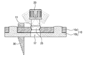
Figure 3 is a cross-sectional structure of the extraction guide device for root extraction according to an embodiment of the disclosed content.
Figure 4 in the extraction guide device for root extraction according to an embodiment of the disclosed content, the position adjustment operation of the position-adjustable support fixing member.
Figure 5 is a state of use of the extraction guide device for root extraction according to an embodiment of the disclosed content.
Figure 6 is another use state of the extraction guide device for root extraction according to an embodiment of the disclosed content.
이하, 첨부된 도면을 참조하여 개시된 내용의 바람직한 실시예의 구성 및 작용효과에 대하여 살펴본다. 참고로, 이하 도면에서, 각 구성요소는 편의 및 명확성을 위하여 생략되거나 개략적으로 도시되었으며, 각 구성요소의 크기는 실제 크기를 반영하는 것은 아니다. 또한 명세서 전체에 걸쳐 동일 참조 부호는 동일 구성요소를 지칭하며 개별 도면에서 동일 구성에 대한 도면 부호는 생략하기로 한다.Hereinafter, with reference to the accompanying drawings looks at with respect to the configuration and effect of the preferred embodiment of the disclosed content. For reference, in the drawings, each component is omitted or schematically illustrated for convenience and clarity, and the size of each component does not reflect the actual size. In addition, the same reference numerals refer to the same components throughout the specification, and reference numerals for the same components in individual drawings will be omitted.
도 1은 개시된 내용의 일 실시예에 따른 치근 발치용 발거가이드장치의 사시도이고, 도 2는 개시된 내용의 일 실시예에 따른 치근 발치용 발거가이드장치의 분해사시도이며, 도 3은 개시된 내용의 일 실시예에 따른 치근 발치용 발거가이드장치의 단면구조도이다.1 is a perspective view of the extraction guide device for root extraction according to an embodiment of the disclosed content, FIG. 2 is an exploded perspective view of the extraction guide device for root extraction according to an embodiment of the disclosed content, and FIG. It is a cross-sectional structural view of the extraction guide device for root extraction according to an embodiment.
개시된 내용의 일 실시예에 따른 치근 발치용 발거가이드장치는 치근 발치시술 시에 발치가 필요한 치근에 드릴 천공을 통해 형성된 치근홀에 발거부재의 하측이 삽입결합된 상태에서 발거부재에 관통결합되어 인접 치아 상에 지지됨에 따라 발치 시술을 위한 지지대를 형성하는 역할을 한다.The extraction guide device for root extraction according to an embodiment of the disclosed content is penetrated to the extraction member in a state where the lower side of the extraction member is inserted into the root hole formed through drilling punctures in the root of the tooth that requires extraction during the root extraction procedure. As it is supported on the teeth, it serves to form a support for the extraction procedure.
치근 발치에 관련되는 드릴, 발거부재, 지렛대 등의 구성과 치근의 발치 방법은 본 출원인이 출원하여 등록받은 바 있는 대한민국 특허등록 제10-1838480호(2018.03.14. 공고)에 개시되어 있는 바, 여기서는 더 이상의 상세설명은 생략하기로 한다.The construction of the tooth root extraction, the construction of the extraction member, the lever, etc. and the extraction method of the tooth root are disclosed in Korean Patent Registration No. 10-1838480 (announced on March 14, 2018), which the applicant has filed and registered. Here, further detailed description will be omitted.
개시된 내용의 일 실시예에 따른 치근 발치용 발거가이드장치는 도 1 내지 도 3에 도시되는 바와 같이, 발치가 필요한 치근 내에 하부가 삽입결합된 발거부재(미도시)에 관통홀을 통해 관통결합되어 발치가 필요한 치근의 인접치아 상에 지지되고 관통홀에는 하부로 갈수록 좁아지다가 다시 확장되는 형태의 곡면지지홈부(11)가 포함되는 발거가이드플레이트(10)와, 정중앙에는 발거부재에 관통결합되는 나사공(21)이 길이방향으로 형성되고 상측에는 회전구동을 위한 래칫기구(미도시)의 결합을 가능하게 하는 래칫체결부(23)가 형성되며 하측에는 관통홀의 곡면지지홈부(11)에 전방향으로 회동가능하게 안착지지되는 회동돌기(25)가 구비되는 견인부재(20)를 포함한다.The extraction guide device for root extraction according to an embodiment of the disclosed content is through-holes through a through-hole to a extraction member (not shown) with a lower portion inserted and inserted into the root of the tooth requiring extraction, as illustrated in FIGS. 1 to 3. It is supported on the adjacent teeth of the root that requires extraction, and the through-hole is a narrowing guide plate (10) that includes a curved support groove (11) that narrows down and expands again. The
여기서, 발거가이드플레이트(10)는 치근 발치 시술시에 발거력을 가하기 위하여 발치가 필요한 치근의 상부에 일종의 지지판을 형성하는 것으로, 발치가 필요한 치근 내에 하부가 삽입결합된 발거부재(미도시)에 관통홀을 통해 관통결합되어 발치가 필요한 치근의 인접 치아 상에 지지된다.Here, the
발거가이드플레이트(10)는, 도 2에 도시되는 바와 같이 강성 재질의 가이드플레이트본체(10a)와, 탄성재질의 완충패드(10b)가 상호 적층결합된 구조로 형성되는 것이 바람직하다.The
가이드플레이트본체(10a)는 예를 들어 지렛대 등의 발치부재에 대한 지지플레이트를 형성하는 것으로, 예를 들어 스테인리스스틸 등과 같은 강성재질로 제조된다. 또한 가이드플레이트본체(10a)의 중앙에는 도 3에 도시되는 바와 같이 하부로 갈수록 좁아지다가 다시 확장되는 형태의 곡면지지공(11)가 형성되고 가이드플레이트본체(10a)의 양측에는 완충패드(10b)의 적층결합을 위한 결합공(13)이 관통형성된다.The
완충패드(10b)는 가이드플레이트본체(10a)의 하부에 적층결합되고 예를 들어 연질 실리콘과 같은 탄성재질로 제조되어 치근 발치시에 인접치아에 가해지는 충격을 완화시키는 역할을 한다. 완충패드(10b)의 상부 양측에는 가이드플레이트본체(10a)의 결합공(13)에 대응되는 결합돌기(15)가 돌출형성되고 완충패드(10b)의 중앙에는 곡면지지홈부(11)에 연통되어 곡면지지홈부(11)와 함께 발거가이드플레이트(10)의 관통결합을 위한 관통홀을 형성하는 연통공(17)이 관통형성된다.The buffer pad (10b) is laminated to the lower portion of the guide plate body (10a) and is made of an elastic material, for example, soft silicone, and serves to alleviate the impact applied to adjacent teeth during tooth extraction.
결과적으로 발치가 필요한 치근에 미리 결합된 발거부재(미도시)에 관통결합되기 위해 발거가이드플레이트(10)에 형성되는 관통홀은, 하부로 갈수록 좁아지다가 다시 확장되는 형태로 가이드플레이트본체(10a)에 형성되는 곡면지지홈부(11)와, 곡면지지홈부(11)에 연통되게 완충패드(10b)에 형성되는 연통공(17)의 조합으로 이루어진다.As a result, the through hole formed in the
발치가 필요한 치근 내에 하부가 삽입결합된 발거부재(미도시)에는 견인부재(20)가 나사결합되어 발거가이드플레이트(10)의 곡면지지홈부(11)에 안착지지된다.The
견인부재(20)는 래칫기구(미도시)에 의해 회전구동되면서 치근과 결합된 발거부재(미도시)를 상승시키기 위한 발거력을 가하는 것으로, 정중앙에는 발치가 필요한 치근 내에 하부가 삽입결합된 발거부재에 나사결합을 통해 관통되기 위한 나사공(21)이 길이방향으로 형성된다.The
또한 견인부재(20)의 상측에는 견인부재(20)의 회전구동을 위한 래칫기구(미도시)의 결합을 가능하게 하는 래칫체결부(23)가 형성되고, 견인부재(20)의 하측에는 도 3에 도시되는 바와 같이 발거가이드플레이트(10)의 곡면지지홈부(11) 상에 전방향으로 회동가능하게 안착지지되는 회동돌기(25)가 구비된다.In addition, a
특히 회동돌기(25)는 발거가이드플레이트(10)의 곡면지지홈부(11)에 대응되는 곡면을 가짐에 따라 견인부재(20)의 회전구동은 물론 전방향으로 일정 각도범위 내의 회동을 가능하게 하며, 견인부재(20)에 의해 가해지는 힘을 전방향으로 분산시키는 역할도 한다.In particular, the
또한 발치가 필요한 치근은 양측에 인접치아가 존재하여 발거가이드플레이트(10)의 양측이 인접치아에 걸쳐져 지지될 수도 있지만, 예를 들어 구강 내에서 양측 단부에 위치되는 어금니의 치근 또는 치아결손부위에 인접하는 치근을 발치하는 경우에는 발거가이드플레이트(10)의 일측만 인접치아에 의해 지지될 뿐 발거가이드플레이트(10)의 타측은 치아의 부존재 또는 결손으로 인해 지지될 수 없어 전체적으로 발거가이드플레이트(10)가 안정적으로 지지되기 어렵다.In addition, the tooth roots that require extraction may have adjacent teeth on both sides, so that both sides of the
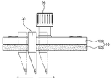
이러한 문제점의 해소를 위해 개시된 내용의 일 실시예에 따른 치근 발치용 발거가이드장치는 발거가이드플레이트(10)에 길이방향으로 슬라이딩 이동가능하게 결합되어 인접치아에 대응되는 지지력을 제공하는 위치조절형 지지고정부재(30)를 더 포함할 수 있다.To solve this problem, the extraction guide device for root extraction according to one embodiment of the disclosed contents is slidably coupled in the longitudinal direction to the
위치조절형 지지고정부재(30)의 상부에는 발거가이드플레이트(10)의 외주면을 둘러싸는 가이드림부(31)가 구비된다. 가이드림부(31)는 발거가이드플레이트(10)에 위치조절형 지지고정부재(30)가 위치이동 가능하게 결합되도록 하는 슬리이딩 결합부를 형성함과 동시에 가이드플레이트본체(10a)와 완충패드(10b)가 적층결합된 상태에서 발거가이드플레이트(10)의 외주면을 둘러쌈에 따라 가이드플레이트본체(10a)와 완충패드(10b)의 임의이탈을 방지하는 발거가이드플레이트(10)의 분리방지부재의 역할을 하는 것으로, 발거가이드플레이트(10)의 외주면에 대응되는 형상을 가진다.A
또한 가이드림부(31)의 상측에는 가이드플레이트본체(10a)의 결합공(13)에 끼워져 상부로 돌출되는 완충패드(10b)의 결합돌기(15)의 단부에 대응되도록 상향융기부(33)가 구비되는 것이 바람직하다. In addition, on the upper side of the
도 4는 전술한 구성을 가지는 위치조절형 지지고정부재의 위치조절작동도이다. 4 is a position adjustment operation diagram of the position-adjustable support fixing member having the above-described configuration.
위치조절형 지지고정부재(30)는 도 4에 도시되는 바와 같이 발거가이드플레이트(10)에 가이드림부(31)가 끼워진 상태에서 발거가이드플레이트(10) 자체를 타고 길이방향으로 위치조절 가능하며, 이로 인해 구강 내에서 양측 단부에 위치되는 어금니의 치근 또는 치아결손부위에 인접하는 치근의 발치시에 해당 치근에 인접되는 위치로 이동되도록 조절될 수 있다.Position-adjustable
도 4에는 위치조절형 지지고정부재(30)가 발거가이드플레이트(10)의 일측에만 길이방향으로 슬라이딩 이동가능하게 결합되는 것으로 도시되어 있으나, 발치가 필요한 치근의 양측 인접치아가 모두 결손된 경우에 위치조절형 지지고정부재(30)는 발거가이드플레이트(10)의 양측에 각각 1개씩 길이방향으로 슬라이딩 이동가능하게 결합될 수 있다(도 6 참조).In FIG. 4, although the position-adjustable
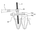
도 5 및 도 6은 개시된 내용의 일 실시예에 따른 치근 발치용 발거가이드장치의 사용상태도이다. 이하 도 1 내지 도 6을 참조하여 개시된 내용의 일 실시예에 따른 치근 발치용 발거가이드장치의 전체 작용을 설명하면 다음과 같다:5 and 6 is a state diagram of the extraction guide device for root extraction according to an embodiment of the disclosed content. Hereinafter, the entire operation of the extraction guide device for root extraction according to an embodiment of the disclosed contents with reference to FIGS. 1 to 6 will be described as follows:
발치가 필요한 치근을 드릴(미도시)로 천공하여 치근홀을 형성한 후, 이 치근홀에 발거부재(3)를 나사결합을 통해 삽입한 다음, 발거부재(3)에 발거가이드플레이트(10)를 관통시킨다. After drilling the roots in need of extraction with a drill (not shown) to form a root hole, insert the
특히 구강 내에서 양측 단부에 위치되는 어금니의 치근 또는 치아결손부위에 인접하는 치근의 발치시에는, 도 5에 도시되는 바와 같이 위치조절형 지지고정부재(30)의 가이드림부(31)를 발거가이드플레이트(10)에 끼운 상태에서 발거가이드플레이트(10)를 따라 위치조절형 지지고정부재(30)를 슬라이딩 이동시켜 인접치아에 대응되는 지지력을 제공될 수 있도록 한다.In particular, when extracting the roots of the molars located at both ends in the oral cavity or the roots adjacent to the dental defects, the
또한 양측 인접치아가 모두 결손된 치근의 발치시에는 도 6에 도시되는 바와 같이 위치조절형 지지고정부재(30)의 가이드림부(31)를 발거가이드플레이트(10)의 양측에 각각 끼운 상태에서 발거가이드플레이트(10)를 따라 위치조절형 지지고정부재(30)를 슬라이딩 이동시켜 인접치아에 대응되는 지지력을 제공될 수 있도록 한다.In addition, when the teeth of both sides adjacent teeth are missing, as shown in FIG. 6, the guide rims 31 of the position-adjustable
개시된 내용의 일 실시예에 따른 치근 발치용 발거가이드장치를 인접치아 상에 안착시킨 상태에서 견인부재(20)를 발거부재(3)에 체결함으로써 견인부재(20)의 회동돌기(25)가 발거가이드플레이트(10)의 곡면지지홈부(11)에 안착지지되도록 한다.The
발거가이드플레이트(10)의 상부에 견인부재(20)가 안착되도록 한 후, 래칫기구(5)를 견인부재(20)의 래칫체결부(23)에 결합시켜 회전구동시켜 치근에 결합된 발거부재(3)를 상방으로 이동시킴에 따라 주변 치조골과 치은조직을 손상하지 않고 치근을 발거할 수 있다.After the
따라서, 개시된 내용의 일 실시예에 따른 치근 발치용 발거가이드장치는, 발거가이드플레이트(10)에 하부로 갈수록 좁아지다가 다시 확장되는 형태의 곡면지지홈부(11)가 포함된 관통홀이 형성되고 견인부재(20)의 하부에는 곡면지지홈부(11)에 대응되어 전방향으로 일정각도로 회동가능한 회동돌기(25)가 돌출형성됨에 따라, 견인부재(20)가 발거가이드플레이트(10)에 대해 전방향에 걸쳐 일정 각도로 회동 가능하게 지지되어 발치시술이 더욱 용이하게 이루어질 수 있게 된다.Therefore, the extraction guide device for root extraction according to an embodiment of the disclosed content is formed through a through hole including a
또한 개시된 내용의 일 실시예에 따른 치근 발치용 발거가이드장치는, 발거부재(3)가 치근에 비스듬히 결합될 경우에도 지렛대를 사용하지 않고 래칫기구(5)의 회전구동만으로 치근과 결합된 발거부재(3)의 발거가 가능함에 따라 지렛대를 이용한 발치로 인해 발거부재(3)가 휘어지는 사례가 미연에 방지될 수 있다.In addition, the extraction guide device for root extraction according to an embodiment of the disclosed contents, even when the
또한 개시된 내용의 일 실시예에 따른 치근 발치용 발거가이드장치는, 발거가이드플레이트(10)에 위치조절형 지지고정부재(30)가 슬라이딩 이동가능하게 결합됨에 따라 구강 내에서 양측 단부에 위치되는 치근 또는 치아결손부위에 인접하는 치근 발치시에 위치조절형 지지고정부재(30)에 의해 인접치아에 대응되는 안정적인 지지가 가능하여 발치시술이 용이하게 이루어질 수 있게 된다.In addition, the extraction guide device for root extraction according to an embodiment of the disclosed contents, the roots located at both ends in the oral cavity as the position-adjustable
이상 첨부된 도면을 참조하여 본 발명의 바람직한 실시예를 설명하였지만, 본 명세서에 기재된 실시예와 도면에 도시된 구성은 본 발명의 가장 바람직한 일 실시예에 불과할 뿐이고 본 발명의 기술적 사상을 모두 대변하는 것은 아니므로, 본 출원시점에 있어서 이들을 대체할 수 있는 다양한 균등물과 변형예들이 있을 수 있음을 이해하여야 한다. 그러므로 이상에서 기술한 실시예들은 모든 면에서 예시적인 것이며 한정적인 것이 아닌 것으로서 이해되어야 하고, 본 발명의 범위는 상세한 설명보다는 후술하는 특허청구범위에 의하여 나타내어지며, 특허청구범위의 의미 및 범위 그리고 그 등가 개념으로부터 도출되는 모든 변경 또는 변형된 형태가 본 발명의 범위에 포함되는 것으로 해석되어야 한다.The preferred embodiments of the present invention have been described above with reference to the accompanying drawings, but the embodiments described in the specification and the configurations shown in the drawings are only the most preferred embodiments of the present invention and represent all technical spirits of the present invention. It should be understood that there may be various equivalents and modifications that can replace them at the time of application. Therefore, the above-described embodiments are to be understood as illustrative and not restrictive in all respects, and the scope of the present invention is indicated by the following claims rather than the detailed description, and the meaning and ranges of the claims It should be construed that any altered or modified form derived from the equivalent concept is included in the scope of the present invention.
3 : 발거부재
5 : 래칫기구
10 : 발거가이드플레이트
10a : 가이드플레이트본체
10b : 완충패드
11 : 곡면지지홈부
13 : 결합공
15 : 결합돌기
17 : 연통공
20 : 견인부재
21 : 나사공
23 : 래칫체결부
25 : 회동돌기
30 : 위치조절형 지지고정부재
31 : 가이드림부
33 : 상향융기부3: Extraction member
5: ratchet mechanism
10: Extraction guide plate
10a: Guide plate body
10b: buffer pad
11: curved support groove
13: coupling hole
15: engaging projection
17: communication hole
20: traction member
21: screw hole
23: ratchet fastening
25: rotating protrusion
30: Position-adjustable support fixing member
31: guide rim
33: upward ridge
Claims (5)
정중앙에는 상기 발거부재에 관통결합되는 나사공이 길이방향으로 형성되고 상측에는 회전구동을 위한 래칫기구의 결합을 가능하게 하는 래칫체결부가 형성되며 하측에는 상기 관통홀의 곡면지지홈부에 전방향으로 회동가능하게 안착지지되는 회동돌기가 구비되는 견인부재를 포함하는 치근 발치용 발거가이드장치.Peeling through a through-hole through a through-hole in the extraction member with the lower part inserted and inserted into the root that needs extraction, supported on the adjacent teeth of the root, and the through-hole includes a curved support groove in a shape that narrows down and expands again. Guide plate; And
In the center, a screw hole penetrating through the extraction member is formed in the longitudinal direction, and a ratchet fastening part is formed on the upper side to enable the ratchet mechanism for rotation driving, and on the lower side, it is possible to rotate in the forward direction to the curved support groove of the through hole. Extraction guide device for root extraction, including a traction member that is provided with a pivot that is seated and supported.
상기 발거가이드플레이트에 길이방향으로 슬라이딩 이동가능하게 결합되는 위치조절형 지지고정부재를 더 포함하는 것을 특징으로 하는 치근 발치용 발거가이드장치.The method according to claim 1,
A extraction guide device for root extraction, further comprising a position-adjustable support fixing member slidably coupled in the longitudinal direction to the extraction guide plate.
상기 위치조절형 지지고정부재의 상부에는 상기 발거가이드플레이트의 외주면을 둘러싸는 가이드림부가 구비되는 것을 특징으로 하는 치근 발치용 발거가이드장치. The method according to claim 2,
A guide guide device for root extraction, characterized in that a guide rim portion surrounding the outer circumferential surface of the guide plate is provided on the top of the position-adjustable support fixing member.
상기 위치조절형 지지고정부재는 상기 발거가이드플레이트의 일측에만 길이방향으로 슬라이딩 이동가능하게 결합되거나 또는 상기 발거가이드플레이트의 양측에 각각 1개씩 길이방향으로 슬라이딩 이동가능하게 결합되는 것을 특징으로 하는 치근 발치용 발거가이드장치.The method according to claim 2,
The position-adjustable support fixing member is slidably coupled in the longitudinal direction only to one side of the extraction guide plate, or a tooth root extraction characterized in that it is slidably coupled in one longitudinal direction to each side of the extraction guide plate, respectively. Dragon extraction guide device.
상기 발거가이드플레이트는, 중앙에는 상기 곡면지지홈부가 형성되고 양측에는 결합공이 관통형성되는 가이드플레이트본체와, 상부양측에 상기 결합공에 대응되는 결합돌기가 돌출형성되어 상기 가이드플레이트본체의 하부에 결합되고 중앙에는 상기 곡면지지홈부에 연통되어 상기 곡면지지홈부와 함께 상기 관통홀을 형성하는 연통공이 관통형성되며 탄성재질로 제조되어 치근 발치시에 상기 인접치아에 가해지는 충격을 완화시키는 완충패드를 포함하는 것을 특징으로 하는 치근 발치용 발거가이드장치.The method according to any one of claims 1 to 4,
The extraction guide plate, the guide plate main body is formed with the curved support groove is formed in the center and through the coupling holes on both sides, and the engaging projections corresponding to the coupling holes on both sides are formed protrudingly coupled to the lower portion of the guide plate body In the center, a communication hole communicating with the curved support groove is formed through the communication hole forming the through hole together with the curved support groove, and it is made of an elastic material, and includes a shock absorber pad to alleviate the impact applied to the adjacent teeth during tooth extraction. Extraction guide device for root extraction, characterized in that.
Priority Applications (1)
| Application Number | Priority Date | Filing Date | Title |
|---|---|---|---|
| KR1020180135425A KR20200052169A (en) | 2018-11-06 | 2018-11-06 | Apparatus for guiding tooth extraction |
Applications Claiming Priority (1)
| Application Number | Priority Date | Filing Date | Title |
|---|---|---|---|
| KR1020180135425A KR20200052169A (en) | 2018-11-06 | 2018-11-06 | Apparatus for guiding tooth extraction |
Publications (1)
| Publication Number | Publication Date |
|---|---|
| KR20200052169A true KR20200052169A (en) | 2020-05-14 |
Family
ID=70736982
Family Applications (1)
| Application Number | Title | Priority Date | Filing Date |
|---|---|---|---|
| KR1020180135425A KR20200052169A (en) | 2018-11-06 | 2018-11-06 | Apparatus for guiding tooth extraction |
Country Status (1)
| Country | Link |
|---|---|
| KR (1) | KR20200052169A (en) |
Citations (2)
| Publication number | Priority date | Publication date | Assignee | Title |
|---|---|---|---|---|
| KR101741071B1 (en) | 2015-05-22 | 2017-05-29 | 김종호 | Luxation appliance for broken root in socket |
| KR101838480B1 (en) | 2017-09-28 | 2018-03-14 | (주) 코웰메디 | Root Extraction Kit |
-
2018
- 2018-11-06 KR KR1020180135425A patent/KR20200052169A/en unknown
Patent Citations (2)
| Publication number | Priority date | Publication date | Assignee | Title |
|---|---|---|---|---|
| KR101741071B1 (en) | 2015-05-22 | 2017-05-29 | 김종호 | Luxation appliance for broken root in socket |
| KR101838480B1 (en) | 2017-09-28 | 2018-03-14 | (주) 코웰메디 | Root Extraction Kit |
Similar Documents
| Publication | Publication Date | Title |
|---|---|---|
| JP5162663B2 (en) | Maxillary sinus elevation drill | |
| US7771199B2 (en) | Bone cutting osteotome tool and method for preparing a surgical sinus-lift osteotomy | |
| US6672870B2 (en) | Method and instrumentation for attaching dentures | |
| ES2360071T3 (en) | MOTORIZED INSTRUMENTS SET TO FACILITATE THE SETTING OF DENTAL IMPLANTS. | |
| JP5834089B2 (en) | Device for bone regeneration and bone extension | |
| KR100981717B1 (en) | Drill Tool for Lifting Sinus | |
| US8398643B2 (en) | Maxillary bone cutting and injection system and method of using the same | |
| KR100946269B1 (en) | Trephine Drill for Implant | |
| EP2428181B1 (en) | Unitary alveolar bone chisel and spreader osteotome for a dental implant | |
| US20060210950A1 (en) | Dental devices | |
| US20160287352A1 (en) | Device for loosening, insertion and removal of dental implants | |
| US20090258328A1 (en) | 5 in 1 dental implant method and apparatus | |
| JP2005525155A (en) | Bone-forming tools used especially for dentistry and instruments for operating them | |
| US20200197130A1 (en) | Dental surgery method and device | |
| JP2008005960A (en) | Instrument for medical operation | |
| CN111263621B (en) | Direction confirming pin and guide screw drill kit for implant fixture | |
| ES2740639T3 (en) | Detachable actuator arm for distraction devices | |
| US20080124672A1 (en) | Dental implant drill guide with handle | |
| KR20200052169A (en) | Apparatus for guiding tooth extraction | |
| JP3222674U (en) | Tooth extraction equipment | |
| CN103976799B (en) | Minimally invasive internal maxillary sinus lifting device for implanting teeth | |
| US20090098509A1 (en) | Dental tooth extraction implement and method thereof | |
| CN111698961B (en) | Dental surgical method and apparatus | |
| KR200365219Y1 (en) | Osteotomes | |
| US20150024346A1 (en) | Method of removing oral root tip |