KR20200050560A - A anode for lithium secondary battery, the manufacturing method of the same and lithium secondary battery comprising the same - Google Patents
A anode for lithium secondary battery, the manufacturing method of the same and lithium secondary battery comprising the same Download PDFInfo
- Publication number
- KR20200050560A KR20200050560A KR1020180133284A KR20180133284A KR20200050560A KR 20200050560 A KR20200050560 A KR 20200050560A KR 1020180133284 A KR1020180133284 A KR 1020180133284A KR 20180133284 A KR20180133284 A KR 20180133284A KR 20200050560 A KR20200050560 A KR 20200050560A
- Authority
- KR
- South Korea
- Prior art keywords
- lithium
- secondary battery
- negative electrode
- lithium secondary
- metal layer
- Prior art date
Links
- 229910052744 lithium Inorganic materials 0.000 title claims abstract description 135
- WHXSMMKQMYFTQS-UHFFFAOYSA-N Lithium Chemical compound [Li] WHXSMMKQMYFTQS-UHFFFAOYSA-N 0.000 title claims abstract description 70
- 238000004519 manufacturing process Methods 0.000 title claims abstract description 22
- 229910052738 indium Inorganic materials 0.000 claims abstract description 33
- APFVFJFRJDLVQX-UHFFFAOYSA-N indium atom Chemical compound [In] APFVFJFRJDLVQX-UHFFFAOYSA-N 0.000 claims abstract description 33
- 238000000034 method Methods 0.000 claims description 43
- OKTJSMMVPCPJKN-UHFFFAOYSA-N Carbon Chemical compound [C] OKTJSMMVPCPJKN-UHFFFAOYSA-N 0.000 claims description 34
- 239000011593 sulfur Substances 0.000 claims description 29
- 229910052717 sulfur Inorganic materials 0.000 claims description 29
- NINIDFKCEFEMDL-UHFFFAOYSA-N Sulfur Chemical compound [S] NINIDFKCEFEMDL-UHFFFAOYSA-N 0.000 claims description 28
- 239000003575 carbonaceous material Substances 0.000 claims description 19
- 239000003792 electrolyte Substances 0.000 claims description 19
- 238000000151 deposition Methods 0.000 claims description 11
- 229910000733 Li alloy Inorganic materials 0.000 claims description 8
- 239000001989 lithium alloy Substances 0.000 claims description 8
- 230000008569 process Effects 0.000 claims description 7
- 229910002804 graphite Inorganic materials 0.000 claims description 6
- 239000010439 graphite Substances 0.000 claims description 6
- 239000002041 carbon nanotube Substances 0.000 claims description 5
- 229910021393 carbon nanotube Inorganic materials 0.000 claims description 5
- 238000010438 heat treatment Methods 0.000 claims description 5
- LHJOPRPDWDXEIY-UHFFFAOYSA-N indium lithium Chemical compound [Li].[In] LHJOPRPDWDXEIY-UHFFFAOYSA-N 0.000 claims description 5
- 238000007740 vapor deposition Methods 0.000 claims description 5
- 239000006229 carbon black Substances 0.000 claims description 4
- 229920000049 Carbon (fiber) Polymers 0.000 claims description 3
- 239000004917 carbon fiber Substances 0.000 claims description 3
- 230000008021 deposition Effects 0.000 claims description 3
- 238000011068 loading method Methods 0.000 claims description 3
- 238000000231 atomic layer deposition Methods 0.000 claims description 2
- 238000005229 chemical vapour deposition Methods 0.000 claims description 2
- 229910021389 graphene Inorganic materials 0.000 claims description 2
- 238000005240 physical vapour deposition Methods 0.000 claims description 2
- 239000010410 layer Substances 0.000 description 43
- 230000000052 comparative effect Effects 0.000 description 30
- -1 specifically Chemical compound 0.000 description 27
- 239000011230 binding agent Substances 0.000 description 20
- 229910052751 metal Inorganic materials 0.000 description 16
- 239000002184 metal Substances 0.000 description 16
- 239000004020 conductor Substances 0.000 description 15
- 238000007599 discharging Methods 0.000 description 14
- 239000007774 positive electrode material Substances 0.000 description 14
- PXHVJJICTQNCMI-UHFFFAOYSA-N nickel Substances [Ni] PXHVJJICTQNCMI-UHFFFAOYSA-N 0.000 description 13
- 210000004027 cell Anatomy 0.000 description 11
- 239000002131 composite material Substances 0.000 description 11
- 239000000203 mixture Substances 0.000 description 11
- GJEAMHAFPYZYDE-UHFFFAOYSA-N [C].[S] Chemical compound [C].[S] GJEAMHAFPYZYDE-UHFFFAOYSA-N 0.000 description 10
- JDZCKJOXGCMJGS-UHFFFAOYSA-N [Li].[S] Chemical compound [Li].[S] JDZCKJOXGCMJGS-UHFFFAOYSA-N 0.000 description 9
- 229910045601 alloy Inorganic materials 0.000 description 9
- 239000000956 alloy Substances 0.000 description 9
- 229910052799 carbon Inorganic materials 0.000 description 9
- 239000010949 copper Substances 0.000 description 9
- 239000003960 organic solvent Substances 0.000 description 9
- 229910052782 aluminium Inorganic materials 0.000 description 8
- 229910052802 copper Inorganic materials 0.000 description 8
- 210000001787 dendrite Anatomy 0.000 description 8
- 239000011148 porous material Substances 0.000 description 8
- 239000007784 solid electrolyte Substances 0.000 description 8
- 239000011888 foil Substances 0.000 description 7
- 229910052759 nickel Inorganic materials 0.000 description 7
- 229920001021 polysulfide Polymers 0.000 description 7
- 239000005077 polysulfide Substances 0.000 description 7
- 150000008117 polysulfides Polymers 0.000 description 7
- 239000002002 slurry Substances 0.000 description 7
- 239000010409 thin film Substances 0.000 description 7
- WEVYAHXRMPXWCK-UHFFFAOYSA-N Acetonitrile Chemical compound CC#N WEVYAHXRMPXWCK-UHFFFAOYSA-N 0.000 description 6
- RYGMFSIKBFXOCR-UHFFFAOYSA-N Copper Chemical compound [Cu] RYGMFSIKBFXOCR-UHFFFAOYSA-N 0.000 description 6
- HBBGRARXTFLTSG-UHFFFAOYSA-N Lithium ion Chemical compound [Li+] HBBGRARXTFLTSG-UHFFFAOYSA-N 0.000 description 6
- ZMXDDKWLCZADIW-UHFFFAOYSA-N N,N-Dimethylformamide Chemical compound CN(C)C=O ZMXDDKWLCZADIW-UHFFFAOYSA-N 0.000 description 6
- XAGFODPZIPBFFR-UHFFFAOYSA-N aluminium Chemical compound [Al] XAGFODPZIPBFFR-UHFFFAOYSA-N 0.000 description 6
- 229910001416 lithium ion Inorganic materials 0.000 description 6
- 229910003002 lithium salt Inorganic materials 0.000 description 6
- 159000000002 lithium salts Chemical class 0.000 description 6
- 229920000642 polymer Polymers 0.000 description 6
- 238000006722 reduction reaction Methods 0.000 description 6
- 239000000126 substance Substances 0.000 description 6
- 239000004698 Polyethylene Substances 0.000 description 5
- BQCADISMDOOEFD-UHFFFAOYSA-N Silver Chemical compound [Ag] BQCADISMDOOEFD-UHFFFAOYSA-N 0.000 description 5
- RTAQQCXQSZGOHL-UHFFFAOYSA-N Titanium Chemical compound [Ti] RTAQQCXQSZGOHL-UHFFFAOYSA-N 0.000 description 5
- 230000008901 benefit Effects 0.000 description 5
- 239000011248 coating agent Substances 0.000 description 5
- 238000000576 coating method Methods 0.000 description 5
- 230000000694 effects Effects 0.000 description 5
- 239000000463 material Substances 0.000 description 5
- 239000011356 non-aqueous organic solvent Substances 0.000 description 5
- 238000007254 oxidation reaction Methods 0.000 description 5
- 229920000573 polyethylene Polymers 0.000 description 5
- 229910052709 silver Inorganic materials 0.000 description 5
- 239000004332 silver Substances 0.000 description 5
- 239000002904 solvent Substances 0.000 description 5
- 239000010935 stainless steel Substances 0.000 description 5
- 229910001220 stainless steel Inorganic materials 0.000 description 5
- 150000003464 sulfur compounds Chemical class 0.000 description 5
- 239000010936 titanium Substances 0.000 description 5
- 229910052719 titanium Inorganic materials 0.000 description 5
- XEEYBQQBJWHFJM-UHFFFAOYSA-N Iron Chemical compound [Fe] XEEYBQQBJWHFJM-UHFFFAOYSA-N 0.000 description 4
- 239000002033 PVDF binder Substances 0.000 description 4
- KDLHZDBZIXYQEI-UHFFFAOYSA-N Palladium Chemical compound [Pd] KDLHZDBZIXYQEI-UHFFFAOYSA-N 0.000 description 4
- 238000006243 chemical reaction Methods 0.000 description 4
- 229920001940 conductive polymer Polymers 0.000 description 4
- 238000001035 drying Methods 0.000 description 4
- 239000010408 film Substances 0.000 description 4
- VNWKTOKETHGBQD-UHFFFAOYSA-N methane Chemical compound C VNWKTOKETHGBQD-UHFFFAOYSA-N 0.000 description 4
- 229920002981 polyvinylidene fluoride Polymers 0.000 description 4
- 229910052725 zinc Inorganic materials 0.000 description 4
- 239000011701 zinc Substances 0.000 description 4
- WNXJIVFYUVYPPR-UHFFFAOYSA-N 1,3-dioxolane Chemical compound C1COCO1 WNXJIVFYUVYPPR-UHFFFAOYSA-N 0.000 description 3
- RTZKZFJDLAIYFH-UHFFFAOYSA-N Diethyl ether Chemical compound CCOCC RTZKZFJDLAIYFH-UHFFFAOYSA-N 0.000 description 3
- XTHFKEDIFFGKHM-UHFFFAOYSA-N Dimethoxyethane Chemical compound COCCOC XTHFKEDIFFGKHM-UHFFFAOYSA-N 0.000 description 3
- LFQSCWFLJHTTHZ-UHFFFAOYSA-N Ethanol Chemical compound CCO LFQSCWFLJHTTHZ-UHFFFAOYSA-N 0.000 description 3
- 229910000846 In alloy Inorganic materials 0.000 description 3
- KFZMGEQAYNKOFK-UHFFFAOYSA-N Isopropanol Chemical compound CC(C)O KFZMGEQAYNKOFK-UHFFFAOYSA-N 0.000 description 3
- 229910018091 Li 2 S Inorganic materials 0.000 description 3
- OKKJLVBELUTLKV-UHFFFAOYSA-N Methanol Chemical compound OC OKKJLVBELUTLKV-UHFFFAOYSA-N 0.000 description 3
- 239000004743 Polypropylene Substances 0.000 description 3
- WYURNTSHIVDZCO-UHFFFAOYSA-N Tetrahydrofuran Chemical compound C1CCOC1 WYURNTSHIVDZCO-UHFFFAOYSA-N 0.000 description 3
- 238000005275 alloying Methods 0.000 description 3
- 235000019241 carbon black Nutrition 0.000 description 3
- 230000007423 decrease Effects 0.000 description 3
- 238000011156 evaluation Methods 0.000 description 3
- 238000005259 measurement Methods 0.000 description 3
- 239000007773 negative electrode material Substances 0.000 description 3
- 239000004745 nonwoven fabric Substances 0.000 description 3
- 229920001155 polypropylene Polymers 0.000 description 3
- 229920005989 resin Polymers 0.000 description 3
- 239000011347 resin Substances 0.000 description 3
- 230000027756 respiratory electron transport chain Effects 0.000 description 3
- 238000012360 testing method Methods 0.000 description 3
- YEJRWHAVMIAJKC-UHFFFAOYSA-N 4-Butyrolactone Chemical compound O=C1CCCO1 YEJRWHAVMIAJKC-UHFFFAOYSA-N 0.000 description 2
- XMWRBQBLMFGWIX-UHFFFAOYSA-N C60 fullerene Chemical compound C12=C3C(C4=C56)=C7C8=C5C5=C9C%10=C6C6=C4C1=C1C4=C6C6=C%10C%10=C9C9=C%11C5=C8C5=C8C7=C3C3=C7C2=C1C1=C2C4=C6C4=C%10C6=C9C9=C%11C5=C5C8=C3C3=C7C1=C1C2=C4C6=C2C9=C5C3=C12 XMWRBQBLMFGWIX-UHFFFAOYSA-N 0.000 description 2
- CURLTUGMZLYLDI-UHFFFAOYSA-N Carbon dioxide Chemical compound O=C=O CURLTUGMZLYLDI-UHFFFAOYSA-N 0.000 description 2
- 229920002134 Carboxymethyl cellulose Polymers 0.000 description 2
- 229910000925 Cd alloy Inorganic materials 0.000 description 2
- VYZAMTAEIAYCRO-UHFFFAOYSA-N Chromium Chemical compound [Cr] VYZAMTAEIAYCRO-UHFFFAOYSA-N 0.000 description 2
- LCGLNKUTAGEVQW-UHFFFAOYSA-N Dimethyl ether Chemical compound COC LCGLNKUTAGEVQW-UHFFFAOYSA-N 0.000 description 2
- IAZDPXIOMUYVGZ-UHFFFAOYSA-N Dimethylsulphoxide Chemical compound CS(C)=O IAZDPXIOMUYVGZ-UHFFFAOYSA-N 0.000 description 2
- ZHNUHDYFZUAESO-UHFFFAOYSA-N Formamide Chemical compound NC=O ZHNUHDYFZUAESO-UHFFFAOYSA-N 0.000 description 2
- SECXISVLQFMRJM-UHFFFAOYSA-N N-Methylpyrrolidone Chemical compound CN1CCCC1=O SECXISVLQFMRJM-UHFFFAOYSA-N 0.000 description 2
- 229910018095 Ni-MH Inorganic materials 0.000 description 2
- 229910018477 Ni—MH Inorganic materials 0.000 description 2
- 229920003171 Poly (ethylene oxide) Polymers 0.000 description 2
- JUJWROOIHBZHMG-UHFFFAOYSA-N Pyridine Chemical compound C1=CC=NC=C1 JUJWROOIHBZHMG-UHFFFAOYSA-N 0.000 description 2
- KAESVJOAVNADME-UHFFFAOYSA-N Pyrrole Chemical compound C=1C=CNC=1 KAESVJOAVNADME-UHFFFAOYSA-N 0.000 description 2
- 229910004283 SiO 4 Inorganic materials 0.000 description 2
- HCHKCACWOHOZIP-UHFFFAOYSA-N Zinc Chemical compound [Zn] HCHKCACWOHOZIP-UHFFFAOYSA-N 0.000 description 2
- 239000006230 acetylene black Substances 0.000 description 2
- 229910052787 antimony Inorganic materials 0.000 description 2
- 229910052790 beryllium Inorganic materials 0.000 description 2
- 229910052792 caesium Inorganic materials 0.000 description 2
- 229910052791 calcium Inorganic materials 0.000 description 2
- 239000002134 carbon nanofiber Substances 0.000 description 2
- 239000006231 channel black Substances 0.000 description 2
- 229910052804 chromium Inorganic materials 0.000 description 2
- 239000011651 chromium Substances 0.000 description 2
- 150000001875 compounds Chemical class 0.000 description 2
- 125000004122 cyclic group Chemical group 0.000 description 2
- 238000003487 electrochemical reaction Methods 0.000 description 2
- 239000008151 electrolyte solution Substances 0.000 description 2
- 229940021013 electrolyte solution Drugs 0.000 description 2
- FKRCODPIKNYEAC-UHFFFAOYSA-N ethyl propionate Chemical compound CCOC(=O)CC FKRCODPIKNYEAC-UHFFFAOYSA-N 0.000 description 2
- LYCAIKOWRPUZTN-UHFFFAOYSA-N ethylene glycol Natural products OCCO LYCAIKOWRPUZTN-UHFFFAOYSA-N 0.000 description 2
- 239000006260 foam Substances 0.000 description 2
- 229910052730 francium Inorganic materials 0.000 description 2
- 229910003472 fullerene Inorganic materials 0.000 description 2
- 239000006232 furnace black Substances 0.000 description 2
- 229910052732 germanium Inorganic materials 0.000 description 2
- 238000005470 impregnation Methods 0.000 description 2
- 230000006872 improvement Effects 0.000 description 2
- 229910003480 inorganic solid Inorganic materials 0.000 description 2
- 239000012212 insulator Substances 0.000 description 2
- 229910052741 iridium Inorganic materials 0.000 description 2
- 229910052742 iron Inorganic materials 0.000 description 2
- 238000003475 lamination Methods 0.000 description 2
- 239000006233 lamp black Substances 0.000 description 2
- 229910052745 lead Inorganic materials 0.000 description 2
- 239000011244 liquid electrolyte Substances 0.000 description 2
- AMXOYNBUYSYVKV-UHFFFAOYSA-M lithium bromide Chemical compound [Li+].[Br-] AMXOYNBUYSYVKV-UHFFFAOYSA-M 0.000 description 2
- KWGKDLIKAYFUFQ-UHFFFAOYSA-M lithium chloride Chemical compound [Li+].[Cl-] KWGKDLIKAYFUFQ-UHFFFAOYSA-M 0.000 description 2
- GLNWILHOFOBOFD-UHFFFAOYSA-N lithium sulfide Chemical compound [Li+].[Li+].[S-2] GLNWILHOFOBOFD-UHFFFAOYSA-N 0.000 description 2
- 229910052749 magnesium Inorganic materials 0.000 description 2
- TZIHFWKZFHZASV-UHFFFAOYSA-N methyl formate Chemical compound COC=O TZIHFWKZFHZASV-UHFFFAOYSA-N 0.000 description 2
- 238000012986 modification Methods 0.000 description 2
- 230000004048 modification Effects 0.000 description 2
- 239000002048 multi walled nanotube Substances 0.000 description 2
- 230000003647 oxidation Effects 0.000 description 2
- 229910052763 palladium Inorganic materials 0.000 description 2
- 239000002245 particle Substances 0.000 description 2
- 229910052697 platinum Inorganic materials 0.000 description 2
- 229920000728 polyester Polymers 0.000 description 2
- 229920001343 polytetrafluoroethylene Polymers 0.000 description 2
- 239000004810 polytetrafluoroethylene Substances 0.000 description 2
- 229910052700 potassium Inorganic materials 0.000 description 2
- 238000002203 pretreatment Methods 0.000 description 2
- RUOJZAUFBMNUDX-UHFFFAOYSA-N propylene carbonate Chemical compound CC1COC(=O)O1 RUOJZAUFBMNUDX-UHFFFAOYSA-N 0.000 description 2
- 238000012827 research and development Methods 0.000 description 2
- 229910052701 rubidium Inorganic materials 0.000 description 2
- 150000003839 salts Chemical class 0.000 description 2
- 229910052710 silicon Inorganic materials 0.000 description 2
- 239000002109 single walled nanotube Substances 0.000 description 2
- 238000004528 spin coating Methods 0.000 description 2
- 238000004544 sputter deposition Methods 0.000 description 2
- 229910052712 strontium Inorganic materials 0.000 description 2
- 229920003048 styrene butadiene rubber Polymers 0.000 description 2
- VZGDMQKNWNREIO-UHFFFAOYSA-N tetrachloromethane Chemical compound ClC(Cl)(Cl)Cl VZGDMQKNWNREIO-UHFFFAOYSA-N 0.000 description 2
- 229910052718 tin Inorganic materials 0.000 description 2
- MIZLGWKEZAPEFJ-UHFFFAOYSA-N 1,1,2-trifluoroethene Chemical compound FC=C(F)F MIZLGWKEZAPEFJ-UHFFFAOYSA-N 0.000 description 1
- ZZXUZKXVROWEIF-UHFFFAOYSA-N 1,2-butylene carbonate Chemical compound CCC1COC(=O)O1 ZZXUZKXVROWEIF-UHFFFAOYSA-N 0.000 description 1
- LZDKZFUFMNSQCJ-UHFFFAOYSA-N 1,2-diethoxyethane Chemical compound CCOCCOCC LZDKZFUFMNSQCJ-UHFFFAOYSA-N 0.000 description 1
- CYSGHNMQYZDMIA-UHFFFAOYSA-N 1,3-Dimethyl-2-imidazolidinon Chemical compound CN1CCN(C)C1=O CYSGHNMQYZDMIA-UHFFFAOYSA-N 0.000 description 1
- XNWFRZJHXBZDAG-UHFFFAOYSA-N 2-METHOXYETHANOL Chemical compound COCCO XNWFRZJHXBZDAG-UHFFFAOYSA-N 0.000 description 1
- ROGIWVXWXZRRMZ-UHFFFAOYSA-N 2-methylbuta-1,3-diene;styrene Chemical compound CC(=C)C=C.C=CC1=CC=CC=C1 ROGIWVXWXZRRMZ-UHFFFAOYSA-N 0.000 description 1
- JWUJQDFVADABEY-UHFFFAOYSA-N 2-methyltetrahydrofuran Chemical compound CC1CCCO1 JWUJQDFVADABEY-UHFFFAOYSA-N 0.000 description 1
- PPDFQRAASCRJAH-UHFFFAOYSA-N 2-methylthiolane 1,1-dioxide Chemical compound CC1CCCS1(=O)=O PPDFQRAASCRJAH-UHFFFAOYSA-N 0.000 description 1
- SBLRHMKNNHXPHG-UHFFFAOYSA-N 4-fluoro-1,3-dioxolan-2-one Chemical compound FC1COC(=O)O1 SBLRHMKNNHXPHG-UHFFFAOYSA-N 0.000 description 1
- LECKFEZRJJNBNI-UHFFFAOYSA-N 4-fluoro-5-methyl-1,3-dioxolan-2-one Chemical compound CC1OC(=O)OC1F LECKFEZRJJNBNI-UHFFFAOYSA-N 0.000 description 1
- 229920013683 Celanese Polymers 0.000 description 1
- OIFBSDVPJOWBCH-UHFFFAOYSA-N Diethyl carbonate Chemical compound CCOC(=O)OCC OIFBSDVPJOWBCH-UHFFFAOYSA-N 0.000 description 1
- KMTRUDSVKNLOMY-UHFFFAOYSA-N Ethylene carbonate Chemical compound O=C1OCCO1 KMTRUDSVKNLOMY-UHFFFAOYSA-N 0.000 description 1
- PIICEJLVQHRZGT-UHFFFAOYSA-N Ethylenediamine Chemical compound NCCN PIICEJLVQHRZGT-UHFFFAOYSA-N 0.000 description 1
- YCKRFDGAMUMZLT-UHFFFAOYSA-N Fluorine atom Chemical compound [F] YCKRFDGAMUMZLT-UHFFFAOYSA-N 0.000 description 1
- 229920002153 Hydroxypropyl cellulose Polymers 0.000 description 1
- 229910008029 Li-In Inorganic materials 0.000 description 1
- 229910012722 Li3N-LiI-LiOH Inorganic materials 0.000 description 1
- 229910012716 Li3N-LiI—LiOH Inorganic materials 0.000 description 1
- 229910012734 Li3N—LiI—LiOH Inorganic materials 0.000 description 1
- 229910013043 Li3PO4-Li2S-SiS2 Inorganic materials 0.000 description 1
- 229910013035 Li3PO4-Li2S—SiS2 Inorganic materials 0.000 description 1
- 229910012810 Li3PO4—Li2S-SiS2 Inorganic materials 0.000 description 1
- 229910012797 Li3PO4—Li2S—SiS2 Inorganic materials 0.000 description 1
- 229910010238 LiAlCl 4 Inorganic materials 0.000 description 1
- 229910015015 LiAsF 6 Inorganic materials 0.000 description 1
- 229910015044 LiB Inorganic materials 0.000 description 1
- 229910013063 LiBF 4 Inorganic materials 0.000 description 1
- 229910013684 LiClO 4 Inorganic materials 0.000 description 1
- 229910010941 LiFSI Inorganic materials 0.000 description 1
- 229910010857 LiI—LiOH Inorganic materials 0.000 description 1
- 229910013553 LiNO Inorganic materials 0.000 description 1
- 229910013870 LiPF 6 Inorganic materials 0.000 description 1
- 229910012513 LiSbF 6 Inorganic materials 0.000 description 1
- 229910012573 LiSiO Inorganic materials 0.000 description 1
- 229910012346 LiSiO4-LiI-LiOH Inorganic materials 0.000 description 1
- 229910012345 LiSiO4-LiI—LiOH Inorganic materials 0.000 description 1
- 229910012348 LiSiO4—LiI—LiOH Inorganic materials 0.000 description 1
- 229910006670 Li—In Inorganic materials 0.000 description 1
- KDXKERNSBIXSRK-UHFFFAOYSA-N Lysine Natural products NCCCCC(N)C(O)=O KDXKERNSBIXSRK-UHFFFAOYSA-N 0.000 description 1
- 239000004472 Lysine Substances 0.000 description 1
- 229920000914 Metallic fiber Polymers 0.000 description 1
- 229910014103 Na-S Inorganic materials 0.000 description 1
- 229910014147 Na—S Inorganic materials 0.000 description 1
- 229910003307 Ni-Cd Inorganic materials 0.000 description 1
- 229920000459 Nitrile rubber Polymers 0.000 description 1
- 239000004642 Polyimide Substances 0.000 description 1
- 229920000265 Polyparaphenylene Polymers 0.000 description 1
- 239000004372 Polyvinyl alcohol Substances 0.000 description 1
- XBDQKXXYIPTUBI-UHFFFAOYSA-M Propionate Chemical compound CCC([O-])=O XBDQKXXYIPTUBI-UHFFFAOYSA-M 0.000 description 1
- BLRPTPMANUNPDV-UHFFFAOYSA-N Silane Chemical compound [SiH4] BLRPTPMANUNPDV-UHFFFAOYSA-N 0.000 description 1
- 229920002472 Starch Polymers 0.000 description 1
- UCKMPCXJQFINFW-UHFFFAOYSA-N Sulphide Chemical compound [S-2] UCKMPCXJQFINFW-UHFFFAOYSA-N 0.000 description 1
- GSEJCLTVZPLZKY-UHFFFAOYSA-N Triethanolamine Chemical compound OCCN(CCO)CCO GSEJCLTVZPLZKY-UHFFFAOYSA-N 0.000 description 1
- BEKPOUATRPPTLV-UHFFFAOYSA-N [Li].BCl Chemical compound [Li].BCl BEKPOUATRPPTLV-UHFFFAOYSA-N 0.000 description 1
- KXKVLQRXCPHEJC-UHFFFAOYSA-N acetic acid trimethyl ester Natural products COC(C)=O KXKVLQRXCPHEJC-UHFFFAOYSA-N 0.000 description 1
- 239000011149 active material Substances 0.000 description 1
- 238000013019 agitation Methods 0.000 description 1
- 150000001336 alkenes Chemical class 0.000 description 1
- 229910000147 aluminium phosphate Inorganic materials 0.000 description 1
- VSCWAEJMTAWNJL-UHFFFAOYSA-K aluminium trichloride Chemical compound Cl[Al](Cl)Cl VSCWAEJMTAWNJL-UHFFFAOYSA-K 0.000 description 1
- 150000003863 ammonium salts Chemical class 0.000 description 1
- 238000004458 analytical method Methods 0.000 description 1
- 229910021383 artificial graphite Inorganic materials 0.000 description 1
- 239000001569 carbon dioxide Substances 0.000 description 1
- 229910002092 carbon dioxide Inorganic materials 0.000 description 1
- 239000002717 carbon nanostructure Substances 0.000 description 1
- 238000010000 carbonizing Methods 0.000 description 1
- 239000001768 carboxy methyl cellulose Substances 0.000 description 1
- 235000010948 carboxy methyl cellulose Nutrition 0.000 description 1
- 239000008112 carboxymethyl-cellulose Substances 0.000 description 1
- 239000001913 cellulose Substances 0.000 description 1
- 229920002678 cellulose Polymers 0.000 description 1
- 239000000919 ceramic Substances 0.000 description 1
- 229910021525 ceramic electrolyte Inorganic materials 0.000 description 1
- 239000011247 coating layer Substances 0.000 description 1
- 238000007796 conventional method Methods 0.000 description 1
- 229920001577 copolymer Polymers 0.000 description 1
- 150000004292 cyclic ethers Chemical class 0.000 description 1
- 238000013461 design Methods 0.000 description 1
- 230000006866 deterioration Effects 0.000 description 1
- 238000011161 development Methods 0.000 description 1
- 238000007607 die coating method Methods 0.000 description 1
- SBZXBUIDTXKZTM-UHFFFAOYSA-N diglyme Chemical compound COCCOCCOC SBZXBUIDTXKZTM-UHFFFAOYSA-N 0.000 description 1
- IEJIGPNLZYLLBP-UHFFFAOYSA-N dimethyl carbonate Chemical compound COC(=O)OC IEJIGPNLZYLLBP-UHFFFAOYSA-N 0.000 description 1
- 150000004862 dioxolanes Chemical class 0.000 description 1
- 238000003618 dip coating Methods 0.000 description 1
- 238000010494 dissociation reaction Methods 0.000 description 1
- 230000005593 dissociations Effects 0.000 description 1
- 238000007606 doctor blade method Methods 0.000 description 1
- 229920001971 elastomer Polymers 0.000 description 1
- 238000003411 electrode reaction Methods 0.000 description 1
- 239000011267 electrode slurry Substances 0.000 description 1
- 238000004146 energy storage Methods 0.000 description 1
- 238000005516 engineering process Methods 0.000 description 1
- 150000002170 ethers Chemical class 0.000 description 1
- JBTWLSYIZRCDFO-UHFFFAOYSA-N ethyl methyl carbonate Chemical compound CCOC(=O)OC JBTWLSYIZRCDFO-UHFFFAOYSA-N 0.000 description 1
- 238000002474 experimental method Methods 0.000 description 1
- 229910052731 fluorine Inorganic materials 0.000 description 1
- 239000011737 fluorine Substances 0.000 description 1
- XUCNUKMRBVNAPB-UHFFFAOYSA-N fluoroethene Chemical compound FC=C XUCNUKMRBVNAPB-UHFFFAOYSA-N 0.000 description 1
- 239000011521 glass Substances 0.000 description 1
- 239000003365 glass fiber Substances 0.000 description 1
- 230000005484 gravity Effects 0.000 description 1
- 238000007756 gravure coating Methods 0.000 description 1
- 150000004820 halides Chemical class 0.000 description 1
- 229910052736 halogen Inorganic materials 0.000 description 1
- 150000002367 halogens Chemical class 0.000 description 1
- 230000002209 hydrophobic effect Effects 0.000 description 1
- 239000001863 hydroxypropyl cellulose Substances 0.000 description 1
- 235000010977 hydroxypropyl cellulose Nutrition 0.000 description 1
- 239000011810 insulating material Substances 0.000 description 1
- 230000010220 ion permeability Effects 0.000 description 1
- 230000001788 irregular Effects 0.000 description 1
- 229920003049 isoprene rubber Polymers 0.000 description 1
- 239000003273 ketjen black Substances 0.000 description 1
- SMBGWMJTOOLQHN-UHFFFAOYSA-N lead;sulfuric acid Chemical compound [Pb].OS(O)(=O)=O SMBGWMJTOOLQHN-UHFFFAOYSA-N 0.000 description 1
- 150000002641 lithium Chemical class 0.000 description 1
- HSZCZNFXUDYRKD-UHFFFAOYSA-M lithium iodide Inorganic materials [Li+].[I-] HSZCZNFXUDYRKD-UHFFFAOYSA-M 0.000 description 1
- ACFSQHQYDZIPRL-UHFFFAOYSA-N lithium;bis(1,1,2,2,2-pentafluoroethylsulfonyl)azanide Chemical compound [Li+].FC(F)(F)C(F)(F)S(=O)(=O)[N-]S(=O)(=O)C(F)(F)C(F)(F)F ACFSQHQYDZIPRL-UHFFFAOYSA-N 0.000 description 1
- VDVLPSWVDYJFRW-UHFFFAOYSA-N lithium;bis(fluorosulfonyl)azanide Chemical compound [Li+].FS(=O)(=O)[N-]S(F)(=O)=O VDVLPSWVDYJFRW-UHFFFAOYSA-N 0.000 description 1
- 239000012528 membrane Substances 0.000 description 1
- YQCIWBXEVYWRCW-UHFFFAOYSA-N methane;sulfane Chemical compound C.S YQCIWBXEVYWRCW-UHFFFAOYSA-N 0.000 description 1
- 125000002496 methyl group Chemical group [H]C([H])([H])* 0.000 description 1
- 238000002156 mixing Methods 0.000 description 1
- 239000002121 nanofiber Substances 0.000 description 1
- 229910021382 natural graphite Inorganic materials 0.000 description 1
- 150000004767 nitrides Chemical class 0.000 description 1
- 150000005181 nitrobenzenes Chemical class 0.000 description 1
- 229910052757 nitrogen Inorganic materials 0.000 description 1
- LYGJENNIWJXYER-UHFFFAOYSA-N nitromethane Chemical compound C[N+]([O-])=O LYGJENNIWJXYER-UHFFFAOYSA-N 0.000 description 1
- 239000012811 non-conductive material Substances 0.000 description 1
- 239000011255 nonaqueous electrolyte Substances 0.000 description 1
- 231100000252 nontoxic Toxicity 0.000 description 1
- 230000003000 nontoxic effect Effects 0.000 description 1
- JRZJOMJEPLMPRA-UHFFFAOYSA-N olefin Natural products CCCCCCCC=C JRZJOMJEPLMPRA-UHFFFAOYSA-N 0.000 description 1
- 150000002898 organic sulfur compounds Chemical class 0.000 description 1
- NBIIXXVUZAFLBC-UHFFFAOYSA-N phosphoric acid Substances OP(O)(O)=O NBIIXXVUZAFLBC-UHFFFAOYSA-N 0.000 description 1
- 150000003014 phosphoric acid esters Chemical class 0.000 description 1
- 230000000704 physical effect Effects 0.000 description 1
- 229920003023 plastic Polymers 0.000 description 1
- 239000004033 plastic Substances 0.000 description 1
- 238000007747 plating Methods 0.000 description 1
- 229920002239 polyacrylonitrile Polymers 0.000 description 1
- 229920001721 polyimide Polymers 0.000 description 1
- 239000005518 polymer electrolyte Substances 0.000 description 1
- 229920000098 polyolefin Polymers 0.000 description 1
- 229920001451 polypropylene glycol Polymers 0.000 description 1
- 229920002451 polyvinyl alcohol Polymers 0.000 description 1
- 239000005373 porous glass Substances 0.000 description 1
- 239000000843 powder Substances 0.000 description 1
- 239000002243 precursor Substances 0.000 description 1
- 238000002360 preparation method Methods 0.000 description 1
- QQONPFPTGQHPMA-UHFFFAOYSA-N propylene Natural products CC=C QQONPFPTGQHPMA-UHFFFAOYSA-N 0.000 description 1
- 230000001681 protective effect Effects 0.000 description 1
- UMJSCPRVCHMLSP-UHFFFAOYSA-N pyridine Natural products COC1=CC=CN=C1 UMJSCPRVCHMLSP-UHFFFAOYSA-N 0.000 description 1
- 239000001008 quinone-imine dye Substances 0.000 description 1
- 230000009467 reduction Effects 0.000 description 1
- 239000004627 regenerated cellulose Substances 0.000 description 1
- 238000007763 reverse roll coating Methods 0.000 description 1
- 239000005060 rubber Substances 0.000 description 1
- 238000000926 separation method Methods 0.000 description 1
- 229910000077 silane Inorganic materials 0.000 description 1
- 239000008107 starch Substances 0.000 description 1
- 235000019698 starch Nutrition 0.000 description 1
- 238000003860 storage Methods 0.000 description 1
- 150000005846 sugar alcohols Polymers 0.000 description 1
- HXJUTPCZVOIRIF-UHFFFAOYSA-N sulfolane Chemical compound O=S1(=O)CCCC1 HXJUTPCZVOIRIF-UHFFFAOYSA-N 0.000 description 1
- 150000003467 sulfuric acid derivatives Chemical class 0.000 description 1
- YLQBMQCUIZJEEH-UHFFFAOYSA-N tetrahydrofuran Natural products C=1C=COC=1 YLQBMQCUIZJEEH-UHFFFAOYSA-N 0.000 description 1
- 239000006234 thermal black Substances 0.000 description 1
- BDZBKCUKTQZUTL-UHFFFAOYSA-N triethyl phosphite Chemical compound CCOP(OCC)OCC BDZBKCUKTQZUTL-UHFFFAOYSA-N 0.000 description 1
- XLYOFNOQVPJJNP-UHFFFAOYSA-N water Substances O XLYOFNOQVPJJNP-UHFFFAOYSA-N 0.000 description 1
Images


Classifications
-
- H—ELECTRICITY
- H01—ELECTRIC ELEMENTS
- H01M—PROCESSES OR MEANS, e.g. BATTERIES, FOR THE DIRECT CONVERSION OF CHEMICAL ENERGY INTO ELECTRICAL ENERGY
- H01M4/00—Electrodes
- H01M4/02—Electrodes composed of, or comprising, active material
- H01M4/13—Electrodes for accumulators with non-aqueous electrolyte, e.g. for lithium-accumulators; Processes of manufacture thereof
- H01M4/134—Electrodes based on metals, Si or alloys
-
- H—ELECTRICITY
- H01—ELECTRIC ELEMENTS
- H01M—PROCESSES OR MEANS, e.g. BATTERIES, FOR THE DIRECT CONVERSION OF CHEMICAL ENERGY INTO ELECTRICAL ENERGY
- H01M10/00—Secondary cells; Manufacture thereof
- H01M10/05—Accumulators with non-aqueous electrolyte
- H01M10/052—Li-accumulators
-
- H—ELECTRICITY
- H01—ELECTRIC ELEMENTS
- H01M—PROCESSES OR MEANS, e.g. BATTERIES, FOR THE DIRECT CONVERSION OF CHEMICAL ENERGY INTO ELECTRICAL ENERGY
- H01M4/00—Electrodes
- H01M4/02—Electrodes composed of, or comprising, active material
- H01M4/04—Processes of manufacture in general
- H01M4/0402—Methods of deposition of the material
- H01M4/0421—Methods of deposition of the material involving vapour deposition
- H01M4/0423—Physical vapour deposition
- H01M4/0426—Sputtering
-
- H—ELECTRICITY
- H01—ELECTRIC ELEMENTS
- H01M—PROCESSES OR MEANS, e.g. BATTERIES, FOR THE DIRECT CONVERSION OF CHEMICAL ENERGY INTO ELECTRICAL ENERGY
- H01M4/00—Electrodes
- H01M4/02—Electrodes composed of, or comprising, active material
- H01M4/04—Processes of manufacture in general
- H01M4/0402—Methods of deposition of the material
- H01M4/0421—Methods of deposition of the material involving vapour deposition
- H01M4/0428—Chemical vapour deposition
-
- H—ELECTRICITY
- H01—ELECTRIC ELEMENTS
- H01M—PROCESSES OR MEANS, e.g. BATTERIES, FOR THE DIRECT CONVERSION OF CHEMICAL ENERGY INTO ELECTRICAL ENERGY
- H01M4/00—Electrodes
- H01M4/02—Electrodes composed of, or comprising, active material
- H01M4/04—Processes of manufacture in general
- H01M4/0471—Processes of manufacture in general involving thermal treatment, e.g. firing, sintering, backing particulate active material, thermal decomposition, pyrolysis
-
- H—ELECTRICITY
- H01—ELECTRIC ELEMENTS
- H01M—PROCESSES OR MEANS, e.g. BATTERIES, FOR THE DIRECT CONVERSION OF CHEMICAL ENERGY INTO ELECTRICAL ENERGY
- H01M4/00—Electrodes
- H01M4/02—Electrodes composed of, or comprising, active material
- H01M4/13—Electrodes for accumulators with non-aqueous electrolyte, e.g. for lithium-accumulators; Processes of manufacture thereof
- H01M4/139—Processes of manufacture
- H01M4/1395—Processes of manufacture of electrodes based on metals, Si or alloys
-
- H—ELECTRICITY
- H01—ELECTRIC ELEMENTS
- H01M—PROCESSES OR MEANS, e.g. BATTERIES, FOR THE DIRECT CONVERSION OF CHEMICAL ENERGY INTO ELECTRICAL ENERGY
- H01M4/00—Electrodes
- H01M4/02—Electrodes composed of, or comprising, active material
- H01M4/36—Selection of substances as active materials, active masses, active liquids
- H01M4/362—Composites
- H01M4/364—Composites as mixtures
-
- H—ELECTRICITY
- H01—ELECTRIC ELEMENTS
- H01M—PROCESSES OR MEANS, e.g. BATTERIES, FOR THE DIRECT CONVERSION OF CHEMICAL ENERGY INTO ELECTRICAL ENERGY
- H01M4/00—Electrodes
- H01M4/02—Electrodes composed of, or comprising, active material
- H01M4/36—Selection of substances as active materials, active masses, active liquids
- H01M4/38—Selection of substances as active materials, active masses, active liquids of elements or alloys
- H01M4/40—Alloys based on alkali metals
- H01M4/405—Alloys based on lithium
-
- H—ELECTRICITY
- H01—ELECTRIC ELEMENTS
- H01M—PROCESSES OR MEANS, e.g. BATTERIES, FOR THE DIRECT CONVERSION OF CHEMICAL ENERGY INTO ELECTRICAL ENERGY
- H01M4/00—Electrodes
- H01M4/02—Electrodes composed of, or comprising, active material
- H01M4/62—Selection of inactive substances as ingredients for active masses, e.g. binders, fillers
- H01M4/624—Electric conductive fillers
- H01M4/625—Carbon or graphite
-
- Y—GENERAL TAGGING OF NEW TECHNOLOGICAL DEVELOPMENTS; GENERAL TAGGING OF CROSS-SECTIONAL TECHNOLOGIES SPANNING OVER SEVERAL SECTIONS OF THE IPC; TECHNICAL SUBJECTS COVERED BY FORMER USPC CROSS-REFERENCE ART COLLECTIONS [XRACs] AND DIGESTS
- Y02—TECHNOLOGIES OR APPLICATIONS FOR MITIGATION OR ADAPTATION AGAINST CLIMATE CHANGE
- Y02E—REDUCTION OF GREENHOUSE GAS [GHG] EMISSIONS, RELATED TO ENERGY GENERATION, TRANSMISSION OR DISTRIBUTION
- Y02E60/00—Enabling technologies; Technologies with a potential or indirect contribution to GHG emissions mitigation
- Y02E60/10—Energy storage using batteries
Abstract
Description
본 발명은 리튬 이차 전지용 음극 및 이의 제조방법 및 이를 포함하는 리튬 이차전지에 관한 것이다.The present invention relates to a negative electrode for a lithium secondary battery, a method of manufacturing the same, and a lithium secondary battery comprising the same.
최근 에너지 저장 기술에 대한 관심이 갈수록 높아지고 있다. 휴대폰, 캠코더 및 노트북 PC, 나아가서는 전기 자동차의 에너지까지 적용분야가 확대되면서 전기화학소자의 연구와 개발에 대한 노력이 점점 구체화되고 있다.Recently, interest in energy storage technology has been increasing. Mobile phones, camcorders and notebook PCs, and furthermore, the field of application to the energy of electric vehicles has been expanded, and efforts for research and development of electrochemical devices are gradually becoming concrete.
전기화학소자는 이러한 측면에서 가장 주목을 받고 있는 분야이고 그 중에서도 충·방전이 가능한 이차전지의 개발은 관심의 초점이 되고 있으며, 최근에는 이러한 전지를 개발함에 있어서 용량 밀도 및 에너지 효율을 향상시키기 위하여 새로운 전극과 전지의 설계에 대한 연구 개발로 진행되고 있다.The electrochemical device is the area that is receiving the most attention in this aspect, and among them, the development of a rechargeable battery that can be charged and discharged has become a focus of interest, and recently, in order to improve capacity density and energy efficiency in developing such a battery. Research and development on new electrode and battery designs are in progress.
현재 적용되고 있는 이차전지 중에서 1990년대 초에 개발된 리튬 이차전지는 수용액 전해액을 사용하는 Ni-MH, Ni-Cd, 황산-납 전지 등의 재래식 전지에 비해서 작동 전압이 높고 에너지 밀도가 월등히 크다는 장점으로 각광을 받고 있다. Among the currently applied secondary batteries, lithium secondary batteries developed in the early 1990s have the advantage of higher operating voltage and significantly higher energy density than conventional batteries such as Ni-MH, Ni-Cd, and sulfuric acid-lead batteries using aqueous electrolyte solutions. Is in the limelight.
특히 리튬-황(Li-S) 전지는 S-S 결합(Sulfur - Sulfur bond)을 갖는 황 계열 물질을 양극 활물질로 사용하고, 리튬 금속을 음극 활물질로 사용하는 이차전지이다. 양극 활물질의 주재료인 황은 자원이 매우 풍부하고, 독성이 없으며, 낮은 원자당 무게를 가지고 있는 장점이 있다. 또한 리튬-황 전지의 이론 방전용량은 1675mAh/g-sulfur이며, 이론 에너지밀도가 2,600Wh/kg로서, 현재 연구되고 있는 다른 전지시스템의 이론 에너지밀도(Ni-MH 전지: 450Wh/kg, Li-FeS 전지: 480Wh/kg, Li-MnO2 전지: 1,000Wh/kg, Na-S 전지: 800Wh/kg)에 비하여 매우 높기 때문에 현재까지 개발되고 있는 전지 중에서 가장 유망한 전지이다.In particular, a lithium-sulfur (Li-S) battery is a secondary battery that uses a sulfur-based material having an SS bond (Sulfur-Sulfur bond) as a positive electrode active material, and uses lithium metal as a negative electrode active material. Sulfur, the main material of the positive electrode active material, is very rich in resources, non-toxic, and has the advantage of having a low weight per atom. In addition, the theoretical discharge capacity of the lithium-sulfur battery is 1675mAh / g-sulfur, and the theoretical energy density is 2,600Wh / kg. The theoretical energy density of other battery systems currently being studied (Ni-MH batteries: 450Wh / kg, Li- FeS battery: 480Wh / kg, Li-MnO 2 battery: 1,000Wh / kg, Na-S battery: 800Wh / kg), so it is the most promising battery developed to date.
리튬-황 전지의 방전 반응 중 음극(Anode)에서는 리튬의 산화 반응이 발생하고, 양극(Cathode)에서는 황의 환원 반응이 발생한다. 방전 전의 황은 환형의 S8 구조를 가지고 있는데, 환원 반응(방전) 시 S-S 결합이 끊어지면서 S의 산화수가 감소하고, 산화 반응(충전) 시 S-S 결합이 다시 형성되면서 S의 산화수가 증가하는 산화-환원 반응을 이용하여 전기 에너지를 저장 및 생성한다. 이런 반응 중 황은 환형의 S8에서 환원 반응에 의해 선형 구조의 리튬 폴리설파이드(Lithium polysulfide, Li2Sx, x = 8, 6, 4, 2)로 변환되게 되며, 결국 이러한 리튬 폴리설파이드가 완전히 환원되면 최종적으로 리튬 설파이드(Lithium sulfide, Li2S)가 생성되게 된다. 각각의 리튬 폴리설파이드로 환원되는 과정에 의해 리튬-황 전지의 방전 거동은 리튬 이온전지와는 달리 단계적으로 방전 전압을 나타내는 것이 특징이다.During the discharge reaction of the lithium-sulfur battery, an oxidation reaction of lithium occurs at the anode, and a reduction reaction of sulfur occurs at the cathode. Sulfur before discharge has a cyclic S 8 structure, and the oxidation of S decreases as the SS bond breaks during the reduction reaction (discharge), and the oxidation of S increases as the SS bond re-forms during the oxidation reaction (charge)- Electric energy is stored and generated using a reduction reaction. Among these reactions, sulfur is converted into a linear structure of lithium polysulfide (Lithium polysulfide, Li 2 S x , x = 8, 6, 4, 2) by a reduction reaction in the cyclic S 8 , and eventually this lithium polysulfide is completely When reduced, lithium sulfide (Li 2 S) is finally formed. The discharge behavior of the lithium-sulfur battery by the process of reduction with each lithium polysulfide is characterized by displaying the discharge voltage step by step unlike the lithium ion battery.
그러나 이러한 리튬-황 전지의 경우, 리튬 메탈을 음극으로 사용하기 때문에 충방전 과정에서 리튬 덴드라이트 (Li dendrite) 성장이 필연적으로 일어나게 된다. 이러한 리튬 덴드라이트가 지속적으로 성장할 경우, 전극 부피 증가, 음극 기공도 증가로 인한 전해액 부족, 덴드라이트가 분리막을 뚫고 성장할 경우 일어나는 쇼트(short)의 발생 등에 의한 안정성 문제를 해결해야 할 필요가 있다. However, in the case of such a lithium-sulfur battery, since lithium metal is used as a negative electrode, lithium dendrite growth inevitably occurs during charging and discharging. When such lithium dendrites are continuously growing, it is necessary to solve stability problems due to an increase in electrode volume, insufficient electrolyte due to an increase in cathode porosity, and shorts that occur when dendrites grow through a separator.
본 발명자들은 다각적인 연구를 수행한 끝에, 리튬 금속층 상에 인듐을 증착시키거나 또는 이를 다시 열처리하여 합금화 시켜 이를 음극으로 사용하게 되면, 전극에서 침상의 덴드라이트 성장을 억제할 수 있다는 것을 확인하여 본 발명을 완성하게 되었다.After conducting various studies, the present inventors confirmed that if indium is deposited on a lithium metal layer or heat-treated again and then alloyed to be used as a negative electrode, dendrite growth of a needle may be suppressed at the electrode. The invention was completed.
따라서, 이에, 본 발명은 음극 중의 리튬 금속 상에 인듐 금속을 증착시켜서 방전용량 및 수명특성이 개선된 리튬 이차전지용 음극 및 그 제조방법을 제공하는 것이다.Accordingly, the present invention is to provide a negative electrode for a lithium secondary battery and a method for manufacturing the lithium secondary battery having improved discharge capacity and life characteristics by depositing indium metal on a lithium metal in the negative electrode.
상기 목적을 달성하기 위해, 본 리튬 금속층; 및 상기 리튬 금속층의 내부 및 표면 중 적어도 일부에 인듐(In)을 포함하는 리튬 이차 전지용 음극을 제공한다.In order to achieve the above object, the present lithium metal layer; And it provides a negative electrode for a lithium secondary battery comprising indium (In) on at least a portion of the interior and surface of the lithium metal layer.
또한, 본 a) 리튬 금속층을 준비하는 단계; 및 b) 상기 리튬 금속층 상에 인듐을 증착하는 단계;를 포함하는 리튬 이차 전지용 음극의 제조방법을 제공한다.In addition, a) preparing a lithium metal layer; And b) depositing indium on the lithium metal layer; provides a method for manufacturing a negative electrode for a lithium secondary battery comprising a.
또한, 본 발명은 상기 음극; 양극; 및 전해질;을 포함하는 리튬 이차 전지를 제공한다.In addition, the present invention is the cathode; anode; And electrolyte; provides a lithium secondary battery comprising a.
본 발명에 따르면, 리튬 금속 층 내부에 인듐 금속이 포함된 음극을 사용함에 따라서, 리튬 음극의 형상을 개선하여 전지의 수명특성을 향상시킬 수 있는 효과가 있다.According to the present invention, according to the use of a negative electrode containing an indium metal in the lithium metal layer, there is an effect that can improve the shape of the lithium negative electrode to improve the life characteristics of the battery.
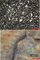
도 1은 실험예 1에 따른 음극의 표면을 확인한 사진이다.
도 2는 실험예 2에 따른 실시예 1과 비교예 1의 음극의 표면을 확인한 사진이다.
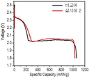
도 3은 실험예 3에 따른 실시예 1과 비교예 1의 최초 방전 프로파일을 나타낸 그래프이다.
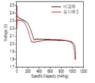
도 4는 실험예 3에 따른 실시예 1과 비교예 1의 두번째 방전 프로파일을 나타낸 그래프이다.
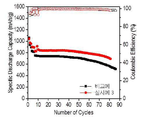
도 5는 실험예 3에 따른 실시예 1과 비교예 1의 수명 특성을 나타낸 그래프이다.
도 6은 실험예 4에 따른 실시예 2와 비교예 1의 음극의 표면을 확인한 사진이다.
도 7은 실험예 4에 따른 실시예 2와 비교예 1의 최초 방전 프로파일을 나타낸 그래프이다.
도 8은 실험예 4에 따른 실시예 2와 비교예 1의 수명 특성을 나타낸 그래프이다.
도 9는 실험예 5에 따른 실시예 3과 비교예 1의 음극의 표면을 확인한 사진이다.
도 10은 실험예 5에 따른 실시예 3과 비교예 1의 최초 방전 프로파일을 나타낸 그래프이다.
도 11은 실험예 5에 따른 실시예 3과 비교예 1의 수명 특성을 나타낸 그래프이다.1 is a photograph confirming the surface of the negative electrode according to Experimental Example 1.
Figure 2 is a photograph confirming the surface of the negative electrode of Example 1 and Comparative Example 1 according to Experimental Example 2.
3 is a graph showing an initial discharge profile of Example 1 and Comparative Example 1 according to Experimental Example 3.
4 is a graph showing a second discharge profile of Example 1 and Comparative Example 1 according to Experimental Example 3.
5 is a graph showing the life characteristics of Example 1 and Comparative Example 1 according to Experimental Example 3.
6 is a photograph confirming the surfaces of the cathodes of Example 2 and Comparative Example 1 according to Experimental Example 4.
7 is a graph showing an initial discharge profile of Example 2 and Comparative Example 1 according to Experimental Example 4.
8 is a graph showing the life characteristics of Example 2 and Comparative Example 1 according to Experimental Example 4.
9 is a photograph confirming the surface of the negative electrode of Example 3 and Comparative Example 1 according to Experimental Example 5.
10 is a graph showing an initial discharge profile of Example 3 and Comparative Example 1 according to Experimental Example 5.
11 is a graph showing the life characteristics of Example 3 and Comparative Example 1 according to Experimental Example 5.
이하, 본 발명이 속하는 기술 분야에서 통상의 지식을 가진 자가 용이하게 실시할 수 있도록 첨부한 도면을 참고로 하여 상세히 설명한다. 그러나 본 발명은 여러 가지 상이한 형태로 구현될 수 있으며, 본 명세서에 한정되지 않는다.Hereinafter, with reference to the accompanying drawings to be easily carried out by those of ordinary skill in the art to which the present invention pertains will be described in detail. However, the present invention can be implemented in many different forms, and is not limited to this specification.
도면에서는 본 발명을 명확하게 설명하기 위해서 설명과 관계없는 부분을 생략하였고, 명세서 전체를 통해 유사한 부분에 대해서는 유사한 도면 부호를 사용하였다. 또한, 도면에서 표시된 구성요소의 크기 및 상대적인 크기는 실제 축척과는 무관하며, 설명의 명료성을 위해 축소되거나 과장된 것일 수 있다.In the drawings, parts not related to the description are omitted in order to clearly describe the present invention, and similar reference numerals are used for similar parts throughout the specification. In addition, the size and relative size of the components indicated in the drawings are independent of the actual scale, and may be reduced or exaggerated for clarity of explanation.
본 명세서 및 청구범위에 사용된 용어나 단어는 통상적이거나 사전적인 의미로 한정해서 해석되어서는 아니되며, 발명자는 그 자신의 발명을 가장 최선의 방법으로 설명하기 위해 용어의 개념을 적절하게 정의할 수 있다는 원칙에 입각하여 본 발명의 기술적 사상에 부합하는 의미와 개념으로 해석되어야만 한다.The terms or words used in the present specification and claims should not be interpreted as being limited to ordinary or lexical meanings, and the inventor can appropriately define the concept of terms in order to best describe his or her invention. Based on the principle that it should be interpreted as meanings and concepts consistent with the technical spirit of the present invention.
본 명세서에서 사용되고 있는 용어 “복합체(composite)”란 두 가지 이상의 재료가 조합되어 물리적·화학적으로 서로 다른 상(phase)를 형성하면서 보다 유효한 기능을 발현하는 물질을 의미한다.As used herein, the term “composite” refers to a substance that combines two or more materials to form physically and chemically different phases and express more effective functions.
리튬-황 전지는 양극 활물질로 황을, 음극 활물질로 리튬 금속을 사용한다. 리튬-황 전지의 방전시 음극에서는 리튬의 산화 반응이 일어나고, 양극에서는 황의 환원 반응이 발생한다. 이때 환원된 황은 음극으로부터 이동되어 온 리튬 이온과 결합하여 리튬 폴리설파이드로 변환되고 최종적으로 리튬 설파이드를 형성하는 반응을 수반한다.The lithium-sulfur battery uses sulfur as a positive electrode active material and lithium metal as a negative electrode active material. When discharging a lithium-sulfur battery, an oxidation reaction of lithium occurs at the negative electrode, and a reduction reaction of sulfur occurs at the positive electrode. At this time, the reduced sulfur is combined with lithium ions that have been moved from the negative electrode and is converted into lithium polysulfide, and finally involves a reaction to form lithium sulfide.
리튬-황 전지는 기존의 리튬 이차 전지에 비해 월등히 높은 이론 에너지 밀도를 가지며, 양극 활물질로 사용되는 황은 자원이 풍부하여 가격이 저렴하므로 전지의 제조단가를 낮출 수 있다는 장점으로 인해 차세대 전지로 각광받고 있다.Lithium-sulfur batteries have a much higher theoretical energy density than conventional lithium secondary batteries, and sulfur used as a positive electrode active material is abundant in resources and has low cost, so it is in the spotlight as a next-generation battery due to the advantage of lowering the manufacturing cost of the battery. have.
이러한 장점에도 불구하고 양극 활물질인 황의 낮은 전기 전도도 및 리튬 이온 전도 특성으로 인해 실제 구동에 있어서는 이론적 에너지 밀도 전부를 구현하는데 어려움이 있다.Despite these advantages, due to the low electrical conductivity and lithium ion conduction properties of the positive electrode active material sulfur, it is difficult to realize all theoretical energy densities in actual driving.
특히, 리튬 메탈을 음극으로 사용하기 때문에 충방전 과정에서 리튬 덴드라이트(Li dendrite)의 성장이 필연적으로 일어나게 되며, 리튬 덴드라이트가 지속적으로 성장할 경우 전극의 부피가 증가하고, 음극의 기공도가 증가함에 따른 전해액의 부족 현상이 일어날 뿐만 아니라, 덴드라이트가 분리막을 뚫고 성장할 경우 일어나는 쇼트(short)의 발생과 이로 인한 안정성 문제 등이 해결해야 할 과제로 남아 있다.In particular, since lithium metal is used as a negative electrode, lithium dendrite inevitably occurs during charging and discharging, and when lithium dendrite continues to grow, the volume of the electrode increases and the porosity of the negative electrode increases. Not only does the shortage of electrolytes occur, but also the problem of stability caused by the occurrence of shorts that occur when dendrite grows through the separation membrane and remains a problem to be solved.
리튬 이차전지용 음극Cathode for lithium secondary battery
본 발명의 리튬 이차 전지용 음극은The negative electrode for a lithium secondary battery of the present invention
리튬 금속층; 및 상기 리튬 금속층의 내부 및 표면 중 적어도 일부에 인듐(In)을 포함한다. Lithium metal layer; And indium (In) on at least a portion of the interior and surface of the lithium metal layer.
본 발명에 있어서 리튬 이차전지용 음극은리튬 금속층의 내부 및 표면 중 적어도 일부에 인듐(In)을 포함하는 구조를 갖는다. In the present invention, the negative electrode for a lithium secondary battery has a structure including indium (In) on at least a portion of the inside and the surface of the lithium metal layer.
본 발명에 있어서 상기 리튬 금속층은 리튬 금속 또는 리튬 합금일 수 있다. 이때 리튬 합금은 리튬과 합금화가 가능한 원소를 포함하고, 구체적으로 리튬과 Si, Sn, C, Pt, Ir, Ni, Cu, Ti, Na, K, Rb, Cs, Fr, Be, Mg, Ca, Sr, Sb, Pb, In, Zn, Ba, Ra, Ge 및 Al로 이루어진 군으로부터 선택되는 1종 이상과의 합금일 수 있다.In the present invention, the lithium metal layer may be a lithium metal or a lithium alloy. At this time, the lithium alloy contains an element capable of alloying with lithium, specifically, lithium and Si, Sn, C, Pt, Ir, Ni, Cu, Ti, Na, K, Rb, Cs, Fr, Be, Mg, Ca, It may be an alloy with one or more selected from the group consisting of Sr, Sb, Pb, In, Zn, Ba, Ra, Ge and Al.
상기 리튬 금속층은 시트 또는 호일의 형태일 수 있으며, 경우에 따라 집전체 상에 리튬 금속 또는 리튬 합금이 건식 공정에 의해 증착 또는 코팅된 형태이거나, 입자 상의 금속 및 합금이 습식 공정 등에 의해 증착 또는 코팅된 형태일 수 있다.The lithium metal layer may be in the form of a sheet or foil, and in some cases, a lithium metal or lithium alloy is deposited or coated on a current collector by a dry process, or a metal or alloy on a particle is deposited or coated by a wet process or the like. Can be in the form of
이 때 리튬 금속층의 형성방법은 특별히 제한되지 않으며, 공지의 금속 박막 형성방법인 라미네이션법, 스퍼터링법 등이 이용될 수 있다. 또한, 집전체에 리튬 박막이 없는 상태로 전지를 조립한 후 초기 충전에 의해 금속판 상에 금속 리튬 박막이 형성되는 경우도 본 발명의 리튬 금속층에 포함된다.At this time, the method of forming the lithium metal layer is not particularly limited, and a known method of forming a metal thin film, a lamination method, a sputtering method, or the like can be used. In addition, the case where the metal lithium thin film is formed on the metal plate by initial charging after assembling the battery without the lithium thin film in the current collector is also included in the lithium metal layer of the present invention.
상기 리튬 금속층은 전극 제조에 용이하도록 전극 형태에 따라 폭이 조절될 수 있다. 리튬 금속층의 두께는 1 내지 500 ㎛, 바람직하게는 10 내지 350 ㎛, 더욱 바람직하게는 30 내지 150 ㎛일 수 있다.The lithium metal layer may be adjusted in width according to the shape of the electrode to facilitate electrode manufacturing. The thickness of the lithium metal layer may be 1 to 500 μm, preferably 10 to 350 μm, and more preferably 30 to 150 μm.
또한, 상기 리튬 금속층은 일 측에 집전체를 더욱 포함할 수 있다. 구체적으로 상기 리튬 금속층은 음극일 수 있으며, 이때 집전체는 음극 집전체가 사용될 수 있다.In addition, the lithium metal layer may further include a current collector on one side. Specifically, the lithium metal layer may be a negative electrode, and the current collector may be a negative electrode current collector.
상기 음극 집전체는 전지에 화학적 변화를 유발하지 않으면서 높은 도전성을 가지는 것이라면 특히 제한하지 않으며, 구리, 알루미늄, 스테인리스 스틸, 아연, 티타늄, 은, 팔라듐, 니켈, 철, 크롬, 이들의 합금 및 이들의 조합으로 이루어진 군으로부터 선택될 수 있다. 상기 스테인리스 스틸은 카본, 니켈, 티탄 또는 은으로 표면 처리될 수 있으며, 상기 합금으로는 알루미늄-카드뮴 합금을 사용할 수 있고, 그 외에도 소성 탄소, 도전재로 표면 처리된 비전도성 고분자, 또는 전도성 고분자 등을 사용할 수도 있다. 일반적으로 음극 집전체로는 구리 박판을 적용한다.The negative electrode current collector is not particularly limited as long as it has high conductivity without causing chemical changes in the battery, and copper, aluminum, stainless steel, zinc, titanium, silver, palladium, nickel, iron, chromium, alloys thereof, and these It can be selected from the group consisting of. The stainless steel may be surface-treated with carbon, nickel, titanium, or silver, and an aluminum-cadmium alloy may be used as the alloy. In addition, calcined carbon, a non-conductive polymer surface-treated with a conductive material, or a conductive polymer, etc. You can also use Generally, a thin copper plate is used as the negative electrode current collector.
또한, 그 형태는 표면에 미세한 요철이 형성된/미형성된 필름, 시트, 호일, 네트, 다공질체, 발포체, 부직포체 등 다양한 형태가 사용될 수 있다.In addition, various forms such as fine / uneven film / sheet, foil, net, porous body, foam, nonwoven fabric with fine irregularities formed on the surface can be used.
또한, 상기 음극 집전체는 3 내지 500 ㎛의 두께 범위인 것을 적용한다. 상기 음극 집전체의 두께가 3 ㎛ 미만이면 집전 효과가 떨어지며, 반면 두께가 500 ㎛를 초과하면 셀을 폴딩(folding)하여 조립하는 경우 가공성이 저하되는 문제점이 있다.In addition, the negative electrode current collector is applied in a thickness range of 3 to 500 μm. If the thickness of the negative electrode current collector is less than 3 μm, the current collecting effect is deteriorated. On the other hand, when the thickness exceeds 500 μm, when the cells are assembled by folding, there is a problem in that workability is deteriorated.
본 발명의 리튬 이차 전지용 음극은 리튬 금속층의 내부 및 표면 중 적어도 일부에 인듐(In)을 포함한다.The negative electrode for a lithium secondary battery of the present invention contains indium (In) on at least a portion of the interior and surface of a lithium metal layer.
상기 리튬 금속층의 내부 및 표면 중 적어도 일부에 인듐(In)을 포함하는 경우, 리튬 금속층 상에 인듐이 증착된 형태로 인듐을 포함할 수도 있고, 상기 증착된 인듐을 열처리하여 인듐-리튬 합금의 형태로 인듐을 포함할 수도 있다.When indium (In) is included in at least a portion of the interior and surface of the lithium metal layer, indium may be included in a form in which indium is deposited on the lithium metal layer, and the deposited indium may be heat treated to form an indium-lithium alloy. It may contain low indium.
이때, 리튬 금속층의 내부 및 표면 중 적어도 일부에 포함되는 인듐의 함량은 리튬 금속 대비 0.1 내지 20 중량%로 포함될 수 있다. 상기 인듐의 함량이 0.1중량%보다 낮으면 보호막으로서 역할을 하기 어려운 문제가 있고, 20중량%보다 높으면 과전압으로 인해 전지 구동에 어려움이 생길 수 있다.At this time, the content of indium contained in at least a part of the interior and surface of the lithium metal layer may be included in 0.1 to 20% by weight compared to the lithium metal. If the content of the indium is lower than 0.1% by weight, there is a problem that it is difficult to serve as a protective film, and if it is higher than 20% by weight, it may be difficult to drive the battery due to overvoltage.
본 발명의 음극은 상기 음극 활물질 이외에 리튬 이온 전도성 물질로 이루어진 전처리층 및 상기 전처리층 상에 형성된 리튬 금속 보호층을 추가적으로 더 포함할 수 있다.The negative electrode of the present invention may further include a pre-treatment layer made of a lithium ion conductive material and a lithium metal protection layer formed on the pre-treatment layer in addition to the negative electrode active material.
리튬 이차 전지용 음극의 제조방법Method for manufacturing negative electrode for lithium secondary battery
본 발명의 리튬 이차 전지용 음극은 (a) 리튬 금속층을 준비하는 단계; 및The negative electrode for a lithium secondary battery of the present invention comprises: (a) preparing a lithium metal layer; And
(b) 상기 리튬 금속층 상에 인듐을 증착하는 단계;를 통하여 제조된다.(b) depositing indium on the lithium metal layer.
먼저, 본 발명의 리튬 이차 전지용 음극의 제조방법은, 리튬 금속층을 준비하는 (a) 단계를 포함한다.First, the method for manufacturing a negative electrode for a lithium secondary battery of the present invention includes the step (a) of preparing a lithium metal layer.
상기 리튬 금속층은 10 내지 150㎛의 두께로 형성될 수 있으며, 리튬 금속층을 형성하는 방법은 특별한 제한이 없다. The lithium metal layer may be formed to a thickness of 10 to 150㎛, the method of forming the lithium metal layer is not particularly limited.
본 발명에 있어서 상기 리튬 금속층은 리튬 금속 또는 리튬 합금일 수 있다. 이때 리튬 합금은 리튬과 합금화가 가능한 원소를 포함하고, 구체적으로 리튬과 Si, Sn, C, Pt, Ir, Ni, Cu, Ti, Na, K, Rb, Cs, Fr, Be, Mg, Ca, Sr, Sb, Pb, In, Zn, Ba, Ra, Ge 및 Al로 이루어진 군으로부터 선택되는 1종 이상과의 합금일 수 있다.In the present invention, the lithium metal layer may be a lithium metal or a lithium alloy. At this time, the lithium alloy contains an element capable of alloying with lithium, specifically, lithium and Si, Sn, C, Pt, Ir, Ni, Cu, Ti, Na, K, Rb, Cs, Fr, Be, Mg, Ca, It may be an alloy with one or more selected from the group consisting of Sr, Sb, Pb, In, Zn, Ba, Ra, Ge and Al.
상기 리튬 금속층은 시트 또는 호일의 형태일 수 있으며, 경우에 따라 집전체 상에 리튬 금속 또는 리튬 합금이 건식 공정에 의해 증착 또는 코팅된 형태이거나, 입자 상의 금속 및 합금이 습식 공정 등에 의해 증착 또는 코팅된 형태일 수 있다.The lithium metal layer may be in the form of a sheet or foil, and in some cases, a lithium metal or lithium alloy is deposited or coated on a current collector by a dry process, or a metal or alloy on a particle is deposited or coated by a wet process or the like. Can be in the form of
이 때 리튬 금속층의 형성방법은 특별히 제한되지 않으며, 공지의 금속 박막 형성방법인 라미네이션법, 스퍼터링법 등이 이용될 수 있다. 또한, 집전체에 리튬 박막이 없는 상태로 전지를 조립한 후 초기 충전에 의해 금속판 상에 금속 리튬 박막이 형성되는 경우도 본 발명의 리튬 금속층에 포함된다.At this time, the method of forming the lithium metal layer is not particularly limited, and a known method of forming a metal thin film, a lamination method, a sputtering method, or the like can be used. In addition, the case where the metal lithium thin film is formed on the metal plate by initial charging after assembling the battery without the lithium thin film in the current collector is also included in the lithium metal layer of the present invention.
상기 리튬 금속층은 전극 제조에 용이하도록 전극 형태에 따라 폭이 조절될 수 있다. 리튬 금속층의 두께는 1 내지 500 ㎛, 바람직하게는 10 내지 350 ㎛, 더욱 구체적으로는 50 내지 200 ㎛일 수 있다.The lithium metal layer may be adjusted in width according to the shape of the electrode to facilitate electrode manufacturing. The thickness of the lithium metal layer may be 1 to 500 μm, preferably 10 to 350 μm, and more specifically 50 to 200 μm.
또한, 상기 리튬 금속층은 일 측에 집전체를 더욱 포함할 수 있다. 구체적으로 상기 리튬 금속층은 음극일 수 있으며, 이때 집전체는 음극 집전체가 사용될 수 있다.In addition, the lithium metal layer may further include a current collector on one side. Specifically, the lithium metal layer may be a negative electrode, and the current collector may be a negative electrode current collector.
상기 음극 집전체는 전지에 화학적 변화를 유발하지 않으면서 높은 도전성을 가지는 것이라면 특히 제한하지 않으며, 구리, 알루미늄, 스테인리스 스틸, 아연, 티타늄, 은, 팔라듐, 니켈, 철, 크롬, 이들의 합금 및 이들의 조합으로 이루어진 군으로부터 선택될 수 있다. 상기 스테인리스 스틸은 카본, 니켈, 티탄 또는 은으로 표면 처리될 수 있으며, 상기 합금으로는 알루미늄-카드뮴 합금을 사용할 수 있고, 그 외에도 소성 탄소, 도전재로 표면 처리된 비전도성 고분자, 또는 전도성 고분자 등을 사용할 수도 있다. 일반적으로 음극 집전체로는 구리 박판을 적용한다.The negative electrode current collector is not particularly limited as long as it has high conductivity without causing chemical changes in the battery, and copper, aluminum, stainless steel, zinc, titanium, silver, palladium, nickel, iron, chromium, alloys thereof, and these It can be selected from the group consisting of. The stainless steel may be surface-treated with carbon, nickel, titanium, or silver, and an aluminum-cadmium alloy may be used as the alloy. In addition, calcined carbon, a non-conductive polymer surface-treated with a conductive material, or a conductive polymer, etc. You can also use Generally, a thin copper plate is used as the negative electrode current collector.
이 후, 본 발명의 리튬 이차 전지용 음극의 제조방법은, 상기 리튬 금속층 상에 인듐을 증착하는 (b) 단계를 포함한다.Thereafter, the method for manufacturing a negative electrode for a lithium secondary battery of the present invention includes the step (b) of depositing indium on the lithium metal layer.
상기 (b) 단계에서는 리튬 금속층 상에 인듐을 증착할 때, 물리 기상증착법(Physical Vapor Deposition), 화학 기상증착법(Chemical Vapor Deposition) 및 원자층 증착법(Atomic Layer Deposition)로 이루어지는 군에서 선택되는 어느 하나 이상의 방법으로 증착할 수 있다.In step (b), when depositing indium on the lithium metal layer, any one selected from the group consisting of a physical vapor deposition method, a chemical vapor deposition method, and an atomic layer deposition method It can be deposited by the above method.
리튬 금속층 상에 인듐을 증착할 때, 상기 기상증착법을 사용하는 것이 바람직하며, 이 경우, 상기 기상증착법은, 공정압력 0.1 내지 100mTorr의 조건, 스퍼터 출력(Sputter power) 50 내지 500W 의 조건, 시료 회전 속도(Sample rotation speed) 1 내지 50 rpm의 조건으로 수행할 수 있다.When depositing indium on the lithium metal layer, it is preferable to use the vapor deposition method, in this case, the vapor deposition method, conditions of a process pressure of 0.1 to 100 mTorr, sputter power (Sputter power) conditions of 50 to 500 W, sample rotation Speed (Sample rotation speed) can be performed under the conditions of 1 to 50 rpm.
또한, 본 발명의 리튬 이차 전지용 음극의 제조방법은, 상기 (b) 단계의 수행 후에, 인듐이 증착된 리튬 금속층을 열처리하는 (c) 단계;를 더 포함할 수 있다.In addition, the method for manufacturing a negative electrode for a lithium secondary battery of the present invention may further include a step (c) of heat treatment of a lithium metal layer on which indium is deposited after performing step (b).
상기 열처리 공정을 거침에 따라서, 본 발명의 음극의 리튬금속과 인듐금속이 합금화 될 수 있으며, 이에 따라서 전지 제조시에 과전압 개선효과 및 수명 특성의 개선효과가 나타날 수 있다. 이 때, 상기 열처리는 130 내지 150℃에서 30초 내지 10분간 수행할 수 있다.By going through the heat treatment process, the lithium metal and the indium metal of the negative electrode of the present invention can be alloyed, and accordingly, an overvoltage improvement effect and an improvement effect in lifespan characteristics may be exhibited during battery manufacturing. In this case, the heat treatment may be performed at 130 to 150 ° C for 30 seconds to 10 minutes.
리튬 이차 전지Lithium secondary battery
본 발명의 일 실시예로서, 리튬 이차 전지는 상술한 음극; 양극; 상기 양극과 음극 사이에 개재되는 분리막; 및 상기 음극, 양극 및 분리막에 함침되어 있으며, 리튬염과 유기용매를 포함하는 전해질을 포함할 수 있으며, 바람직하게 상기 리튬 이차 전지는 양극 내에 황 화합물을 포함하는 리튬-황 전지일 수 있다.As an embodiment of the present invention, the lithium secondary battery includes the negative electrode described above; anode; A separator interposed between the anode and the cathode; And an electrolyte impregnated in the negative electrode, the positive electrode and the separator, and containing a lithium salt and an organic solvent, and preferably, the lithium secondary battery may be a lithium-sulfur battery containing a sulfur compound in the positive electrode.
본 발명에서는 황-탄소 복합체가 리튬 이차 전지의 양극 활물질로서 바람직하게 사용이 가능하다. In the present invention, the sulfur-carbon composite can be preferably used as a positive electrode active material of a lithium secondary battery.
상기 황-탄소 복합체는 다공성 탄소재와 황 화합물을 포함하여 구성된다.The sulfur-carbon composite is composed of a porous carbon material and a sulfur compound.
상기 다공성 탄소재는 양극 활물질인 황이 균일하고 안정적으로 고정화될 수 있는 골격을 제공하고 황의 전기 전도도를 보완하여 전기화학 반응이 원활하게 진행될 수 있도록 한다.The porous carbon material provides a skeleton in which the positive electrode active material sulfur can be immobilized uniformly and stably, and complements the electrical conductivity of sulfur, so that the electrochemical reaction can proceed smoothly.
상기 다공성 탄소재는 일반적으로 다양한 탄소 재질의 전구체를 탄화시킴으로써 제조될 수 있다. 상기 다공성 탄소재는 내부에 일정하지 않은 기공을 포함하며 상기 기공의 평균 직경은 1 내지 200 ㎚ 범위이며, 기공도 또는 공극률은 다공성 전체 체적의 10 내지 90 % 범위일 수 있다. 만일 상기 기공의 평균 직경이 상기 범위 미만인 경우 기공 크기가 분자 수준에 불과하여 황의 함침이 불가능하며, 이와 반대로 상기 범위를 초과하는 경우 다공성 탄소의 기계적 강도가 약화되어 전극의 제조공정에 적용하기에 바람직하지 않다.The porous carbon material can be generally produced by carbonizing precursors of various carbon materials. The porous carbon material includes irregular pores therein, and the average diameter of the pores is in the range of 1 to 200 nm, and the porosity or porosity may range from 10 to 90% of the total volume of the porous. If the average diameter of the pores is less than the above range, impregnation of sulfur is impossible because the pore size is only at the molecular level. Conversely, when it exceeds the above range, the mechanical strength of the porous carbon is weakened, which is preferable for application in the electrode manufacturing process. Does not.
상기 다공성 탄소재의 형태는 구형, 봉형, 침상형, 판상형, 튜브형 또는 벌크형으로 리튬 이차 전지에 통상적으로 사용되는 것이라면 제한없이 사용될 수 있다.The shape of the porous carbon material may be spherical, rod-shaped, needle-shaped, plate-shaped, tubular, or bulk-type, and may be used without limitation as long as it is commonly used in lithium secondary batteries.
상기 다공성 탄소재는 다공성 구조이거나 비표면적이 높은 것으로 당업계에서 통상적으로 사용되는 것이라면 어느 것이든 무방하다. 예를 들어, 상기 다공성 탄소재로는 그래파이트(graphite); 그래핀(graphene); 덴카 블랙, 아세틸렌 블랙, 케첸 블랙, 채널 블랙, 퍼네이스 블랙, 램프 블랙, 서머 블랙 등의 카본 블랙; 단일벽 탄소나노튜브(SWCNT), 다중벽 탄소나노튜브(MWCNT) 등의 탄소나노튜브(CNT); 그라파이트 나노파이버(GNF), 카본 나노파이버(CNF), 활성화 탄소 파이버(ACF) 등의 탄소 섬유; 및 활성탄소로 이루어진 군으로부터 선택된 1종 이상일 수 있으나 이에 제한되지 않는다.The porous carbon material may be either a porous structure or a high specific surface area as long as it is commonly used in the art. For example, the porous carbon material includes graphite; Graphene; Carbon blacks such as denka black, acetylene black, ketjen black, channel black, furnace black, lamp black, and summer black; Carbon nanotubes (CNT) such as single-walled carbon nanotubes (SWCNT) and multi-walled carbon nanotubes (MWCNT); Carbon fibers such as graphite nanofiber (GNF), carbon nanofiber (CNF), and activated carbon fiber (ACF); And it may be at least one selected from the group consisting of activated carbon, but is not limited thereto.
상기 황 화합물은 무기 황(S8), Li2Sn(n ≥ 1), 유기 황 화합물 및 탄소-황 폴리머[(C2Sx)n, x=2.5 내지 50, n ≥ 2]로 이루어진 군으로부터 선택된 1종 이상일 수 있다. 바람직하게는 무기 황(S8)을 사용할 수 있다.The sulfur compound is composed of inorganic sulfur (S 8 ), Li 2 S n (n ≥ 1), an organic sulfur compound and a carbon-sulfur polymer [(C 2 S x ) n , x = 2.5 to 50, n ≥ 2] It may be one or more selected from the group. Preferably, inorganic sulfur (S 8 ) can be used.
본 발명에 따른 황-탄소 복합체에서 전술한 황 화합물과 다공성 탄소재의 중량비는 9:1 내지 5:5일 수 있다. 만약 상기 황 화합물의 함량이 중량비로 50 중량% 미만인 경우 다공성 탄소재의 함량이 증가함에 따라 양극 슬러리 제조시에 필요한 바인더 첨가량이 늘어난다. 이러한 바인더 첨가량의 증가는 결국 전극의 면저항을 증가시키기게 되고 전자 이동(electron pass)을 막는 절연체 역할을 하게 되어 셀 성능을 저하시킬 수 있다. 반대로 상기 중량비 범위를 초과하는 경우 황이 그들끼리 뭉치게 되고, 전자를 받기 어려워서 전극 반응에 직접적으로 참여하기 어렵게 될 수 있다.In the sulfur-carbon composite according to the present invention, the weight ratio of the aforementioned sulfur compound and the porous carbon material may be 9: 1 to 5: 5. If the content of the sulfur compound is less than 50% by weight, as the content of the porous carbon material increases, the amount of binder addition required in preparing the positive electrode slurry increases. The increase in the amount of the binder added eventually increases the sheet resistance of the electrode and acts as an insulator preventing electron pass, which can degrade cell performance. Conversely, when the weight ratio range is exceeded, sulfur may be aggregated between them, and it may be difficult to directly participate in the electrode reaction due to difficulty receiving electrons.
또한, 상기 황은 상기 다공성 탄소재의 기공 내부뿐만 아니라 표면에 위치하며 이때 상기 다공성 탄소재의 외부 전체 표면의 100% 미만, 바람직하게는 1 내지 95 %, 더욱 바람직하게는 60 내지 90 % 영역에 존재할 수 있다. 상기 황이 다공성 탄소재의 표면에 상기 범위 내에 있을 때 전자 전달 면적 및 전해액의 젖음성 면에서 최대 효과를 나타낼 수 있다. 구체적으로, 상기 범위 영역에서 황이 다공성 탄소재의 표면에 얇고 고르게 함침되므로 충방전 과정에서 전자 전달 접촉 면적을 증가시킬 수 있다. 만약, 상기 황이 다공성 탄소재의 표면의 100% 영역에 위치하는 경우, 상기 다공성 탄소재가 완전히 황으로 덮여 전해액의 젖음성이 떨어지고 전극 내 포함되는 도전재와 접촉성이 떨어져 전자 전달을 받지 못해 반응에 참여할 수 없게 된다.In addition, the sulfur is located on the surface as well as inside the pores of the porous carbon material, wherein less than 100%, preferably 1 to 95%, more preferably 60 to 90% of the entire outer surface of the porous carbon material is present Can be. When the sulfur is within the above range on the surface of the porous carbon material, it can exhibit the maximum effect in terms of electron transfer area and wettability of the electrolyte. Specifically, since the sulfur is thinly and evenly impregnated on the surface of the porous carbon material in the above-described range region, it is possible to increase the area of the electron transfer contact during charging and discharging. If, when the sulfur is located in the region of 100% of the surface of the porous carbon material, the porous carbon material is completely covered with sulfur, so that the wettability of the electrolyte decreases and the contact property with the conductive material contained in the electrode does not receive electron transfer and participate in the reaction. It becomes impossible.
상기 황-탄소 복합체는 구조체 내 다양한 크기의 기공 및 3차원적으로 상호 연결되며 규칙적으로 정렬된 기공들로 인해 황을 높은 함량으로 담지할 수 있다. 이로 인해 전기화학 반응으로 용해성이 있는 폴리설파이드가 생성되더라도 황-탄소 복합체 내부에 위치할 수 있게 되면, 폴리설파이드 용출 시에도 3차원으로 얽혀 있는 구조가 유지되어 양극 구조가 붕괴되는 현상을 억제시킬 수 있다. 그 결과, 상기 황-탄소 복합체를 포함하는 리튬 이차 전지는 고로딩(high loading)에서도 고용량을 구현할 수 있다는 장점이 있다. The sulfur-carbon composite is capable of supporting a high content of sulfur due to pores of various sizes and three-dimensional interconnection in the structure and regularly aligned pores. Due to this, even if soluble polysulfide is generated by the electrochemical reaction, if it can be located inside the sulfur-carbon composite, the three-dimensional entangled structure is maintained even when the polysulfide is eluted to suppress the collapse of the anode structure. have. As a result, the lithium secondary battery including the sulfur-carbon composite has an advantage that a high capacity can be realized even at high loading.
이에, 본 발명에 따른 황-탄소 복합체의 황 로딩량은 1 ~ 20 mg/cm2가 될 수 있다.Thus, the sulfur-loading amount of the sulfur-carbon composite according to the present invention may be 1 to 20 mg / cm 2 .
상기 양극은 양극 집전체 상에 양극 활물질층 형성용 조성물을 도포 및 건조하여 제작된다. 상기 양극 활물질층 형성용 조성물은 상술한 황-탄소 복합체를 도전재 및 바인더와 혼합한 후, 40 내지 70 ℃에서 4시간 내지 12시간 동안 건조하여 제조한다.The positive electrode is produced by applying and drying a composition for forming a positive electrode active material layer on a positive electrode current collector. The composition for forming the positive electrode active material layer is prepared by mixing the above-described sulfur-carbon composite with a conductive material and a binder, and then drying at 40 to 70 ° C. for 4 to 12 hours.
구체적으로 상기 제조된 황-탄소 복합체에 추가적인 도전성을 부여하기 위하여, 상기 양극 조성물에는 도전재가 추가될 수 있다. 상기 도전재는 전자가 양극 내에서 원활하게 이동하도록 하기 위한 역할을 하는 것으로, 전지에 화학적 변화를 유발하지 않으면서 도전성이 우수하고 넓은 표면적을 제공할 수 있는 것이면 특별한 제한이 없으나, 바람직하게는 탄소계 물질을 사용한다.Specifically, in order to impart additional conductivity to the prepared sulfur-carbon composite, a conductive material may be added to the positive electrode composition. The conductive material plays a role for the electrons to move smoothly within the anode, and is not particularly limited as long as it is capable of providing excellent conductivity and a large surface area without causing chemical changes to the battery, but is preferably carbon-based. Use materials.
상기 탄소계 물질로는 천연 흑연, 인조 흑연, 팽창 흑연, 그래핀(Graphene)과 같은 흑연(Graphite)계, 활성탄(Active carbon)계, 채널 블랙(Channel black), 퍼니스 블랙(Furnace black), 써말 블랙(Thermal black), 컨택트 블랙(Contact black), 램프 블랙(Lamp black), 아세틸렌 블랙(Acetylene black)과 같은 카본 블랙(Carbon black)계; 탄소 섬유(Carbon fiber)계, 탄소나노튜브(Carbon nanotube: CNT), 풀러렌(Fullerene)과 같은 탄소 나노 구조체 및 이들의 조합으로 이루어진 군으로부터 선택된 1종을 사용할 수 있다. The carbon-based materials include natural graphite, artificial graphite, expanded graphite, graphite-based graphite, active carbon-based, channel black, furnace black, and thermal. Carbon black, such as Thermal black, Contact black, Lamp black, Acetylene black; Carbon fiber, carbon nanotubes (CNT), carbon nanostructures such as fullerene (Fullerene), and a combination thereof may be used.
상기 탄소계 물질 이외에도, 목적에 따라 금속 메쉬 등의 금속성 섬유; 구리(Cu), 은(Ag), 니켈(Ni), 알루미늄(Al) 등의 금속성 분말; 또는 폴리페닐렌 유도체 등의 유기 도전성 재료도 사용할 수 있다. 상기 도전성 재료들은 단독 또는 혼합하여 사용될 수 있다. In addition to the carbon-based material, metallic fibers such as a metal mesh depending on the purpose; Metallic powders such as copper (Cu), silver (Ag), nickel (Ni), and aluminum (Al); Alternatively, organic conductive materials such as polyphenylene derivatives can also be used. The conductive materials may be used alone or in combination.
또한 상기 양극 활물질에 집전체에 대한 부착력을 제공하기 위하여, 상기 양극 조성물에는 바인더가 추가적으로 포함될 수 있다. 상기 바인더는 용매에 잘 용해되어야 하며, 양극 활물질과 도전재와의 도전 네트워크를 잘 구성해주어야 할 뿐만 아니라 전해액의 함침성도 적당히 가져야 한다.In addition, in order to provide adhesion to the current collector to the positive electrode active material, a binder may be additionally included in the positive electrode composition. The binder should be well soluble in a solvent, not only should a well-constructed conductive network between the positive electrode active material and the conductive material, but also should have adequate impregnation properties of the electrolyte.
본 발명에 적용 가능한 바인더는 당해 업계에서 공지된 모든 바인더들일 수 있고, 구체적으로는, 폴리비닐리덴 플루오라이드(Polyvinylidene fluoride, PVdF) 또는 폴리테트라플루오로에틸렌(Polytetrafluoroethylene, PTFE)을 포함하는 불소 수지계 바인더; 스티렌-부타디엔 고무, 아크릴로니트릴-부티디엔 고무, 스티렌-이소프렌 고무를 포함하는 고무계 바인더; 카르복시메틸셀룰로우즈(CMC), 전분, 히드록시프로필셀룰로우즈, 재생 셀룰로우즈를 포함하는 셀룰로오스계 바인더; 폴리 알코올계 바인더; 폴리에틸렌, 폴리프로필렌를 포함하는 폴리 올레핀계 바인더; 폴리 이미드계 바인더, 폴리 에스테르계 바인더, 실란계 바인더;로 이루어진 군에서 선택된 1종 또는 2종 이상의 혼합물이거나 공중합체일 수 있으나, 이에 제한되지 않음은 물론이다.The binder applicable to the present invention may be all binders known in the art, and specifically, a fluorine resin-based binder including polyvinylidene fluoride (PVdF) or polytetrafluoroethylene (PTFE) ; Rubber-based binders including styrene-butadiene rubber, acrylonitrile-butadiene rubber, and styrene-isoprene rubber; Cellulose-based binders including carboxymethylcellulose (CMC), starch, hydroxypropylcellulose, and regenerated cellulose; Poly alcohol-based binders; Polyolefin-based binders including polyethylene and polypropylene; Polyimide-based binder, polyester-based binder, silane-based binder; may be a mixture or copolymer of one or more selected from the group consisting of, but is not limited to, of course.
상기 바인더 수지의 함량은 상기 양극 총중량을 기준으로 0.5 ~ 30 중량%일 수 있으나, 이에만 한정되는 것은 아니다. 상기 바인더 수지의 함량이 0.5 중량% 미만인 경우에는, 양극의 물리적 성질이 저하되어 양극 활물질과 도전재가 탈락할 수 있고, 30 중량%를 초과하는 경우에는 양극에서 활물질과 도전재의 비율이 상대적으로 감소되어 전지 용량이 감소될 수 있다.The content of the binder resin may be 0.5 to 30% by weight based on the total weight of the positive electrode, but is not limited thereto. When the content of the binder resin is less than 0.5% by weight, the physical properties of the positive electrode may deteriorate and the positive electrode active material and the conductive material may drop off, and when it exceeds 30% by weight, the ratio of the active material and the conductive material in the positive electrode is relatively reduced. Battery capacity can be reduced.
양극 조성물을 슬러리 상태로 제조하기 위한 용매는 건조가 용이해야하며, 바인더를 잘 용해시킬 수 있되, 양극 활물질 및 도전재는 용해시키지 않고 분산 상태로 유지시킬 수 있는 것이 가장 바람직하다. 용매가 양극 활물질을 용해시킬 경우에는 슬러리에서 황의 비중(D = 2.07)이 높기 때문에 황이 슬러리에서 가라앉게 되어 코팅시 집전체에 황이 몰려 도전 네트워크에 문제가 생겨 전지의 작동에 문제가 발생하는 경향이 있다.The solvent for preparing the positive electrode composition in a slurry state should be easy to dry, and can dissolve the binder well, but it is most preferable that the positive electrode active material and the conductive material can be maintained in a dispersed state without dissolving. When the solvent dissolves the positive electrode active material, the specific gravity of sulfur in the slurry (D = 2.07) is high, so the sulfur sinks in the slurry, and when it is coated, sulfur collects in the current collector, causing problems in the conductive network, which tends to cause problems in battery operation. have.
본 발명에 따른 용매는 물 또는 유기 용매가 가능하며, 상기 유기 용매는 디메틸포름아미드, 이소프로필알콜, 아세토니트릴, 메탄올, 에탄올, 테트라하이드로퓨란 군으로부터 선택되는 1종 이상을 포함하는 유기 용매가 적용 가능하다.The solvent according to the present invention may be water or an organic solvent, and the organic solvent includes an organic solvent including one or more selected from the group consisting of dimethylformamide, isopropyl alcohol, acetonitrile, methanol, ethanol, and tetrahydrofuran. It is possible.
상기 양극 조성물의 혼합은 통상의 혼합기, 예컨대 레이트스 믹서, 고속 전단 믹서, 호모 믹서 등을 이용하여 통상의 방법으로 교반할 수 있다.The positive electrode composition may be mixed by a conventional method using a conventional mixer, such as a rate mixer, a high-speed shear mixer, or a homo mixer.
상기 양극 조성물을 집전체에 도포하고, 진공 건조하여 양극을 형성할 수 있다. 상기 슬러리는 슬러리의 점도 및 형성하고자 하는 양극의 두께에 따라 적절한 두께로 집전체에 코팅할 수 있으며, 바람직하게는 10 내지 300 ㎛ 범위 내에서 적절히 선택할 수 있다.The positive electrode composition may be applied to a current collector and dried in vacuum to form an positive electrode. The slurry may be coated on the current collector to an appropriate thickness depending on the viscosity of the slurry and the thickness of the anode to be formed, and may be appropriately selected within a range of 10 to 300 μm.
이때 상기 슬러리를 코팅하는 방법으로 그 제한은 없으며, 예컨대, 닥터 블레이드 코팅(Doctor blade coating), 딥 코팅(Dip coating), 그라비어 코팅(Gravure coating), 슬릿 다이 코팅(Slit die coating), 스핀 코팅(Spin coating), 콤마 코팅(Comma coating), 바 코팅(Bar coating), 리버스 롤 코팅(Reverse roll coating), 스크린 코팅(Screen coating), 캡 코팅(Cap coating) 방법 등을 수행하여 제조할 수 있다.At this time, the method of coating the slurry is not limited, for example, doctor blade coating, dip coating, gravure coating, slit die coating, and spin coating ( Spin coating, comma coating, bar coating, reverse roll coating, screen coating, and cap coating may be performed.
상기 양극 집전체로는 일반적으로 3 ~ 500 ㎛의 두께로 만들 수 있고, 전지에 화학적 변화를 유발하지 않으면서 높은 도전성을 가지는 것이라면 특히 제한하지 않는다. 예컨대 스테인레스 스틸, 알루미늄, 구리, 티타늄 등의 전도성 금속을 사용할 수 있고, 바람직하게는 알루미늄 집전체를 사용할 수 있다. 이러한 양극 집전체는 필름, 시트, 호일, 네트, 다공질체, 발포체 또는 부직포체 등 다양한 형태가 가능하다.The positive electrode current collector may be generally 3 to 500 μm thick, and is not particularly limited as long as it has high conductivity without causing chemical changes in the battery. For example, a conductive metal such as stainless steel, aluminum, copper, or titanium can be used, and preferably, an aluminum current collector can be used. The positive electrode current collector may be in various forms such as a film, sheet, foil, net, porous body, foam, or nonwoven fabric.
상기 양극과 음극 사이에 개재되는 분리막은 양극과 음극을 서로 분리 또는 절연시키고, 양극과 음극 사이에 리튬 이온의 수송을 가능하게 하는 것으로 다공성 비전도성 또는 절연성 물질로 이루어질 수 있다. 이러한 분리막은 높은 이온 투과도 및 기계적 강도를 가지는 절연체로서 얇은 박막 또는 필름과 같은 독립적인 부재일 수도 있고, 양극 및/또는 음극에 부가된 코팅층일 수도 있다. 또한 전해질로서 폴리머 등의 고체 전해질이 사용되는 경우에는 고체 전해질이 분리막을 겸할 수도 있다.The separator interposed between the positive electrode and the negative electrode separates or insulates the positive electrode and the negative electrode from each other and enables transport of lithium ions between the positive electrode and the negative electrode, and may be made of a porous non-conductive or insulating material. The separator is an insulator having high ion permeability and mechanical strength, and may be an independent member such as a thin film or a film, or a coating layer added to the anode and / or the cathode. In addition, when a solid electrolyte such as a polymer is used as the electrolyte, the solid electrolyte may also serve as a separator.
상기 분리막의 기공 직경은 일반적으로 0.01 ~ 10 ㎛이고, 두께는 일반적으로 5 ~ 300 ㎛이 바람직하며, 이러한 분리막으로는, 유리 전해질(Glass electrolyte), 고분자 전해질 또는 세라믹 전해질 등이 사용될 수 있다. 예컨대 내화학성 및 소수성의 폴리프로필렌 등의 올레핀계 폴리머, 유리섬유 또는 폴리에틸렌 등으로 만들어진 시트나 부직포, 크라프트지 등이 사용된다. 현재 시판중인 대표적인 예로는 셀가드 계열(CelgardR 2400, 2300 Hoechest Celanese Corp. 제품), 폴리프로필렌 분리막(Ube Industries Ltd. 제품 또는 Pall RAI사 제품), 폴리에틸렌 계열(Tonen 또는 Entek) 등이 있다.The pore diameter of the separator is generally 0.01 to 10 μm, and the thickness is generally 5 to 300 μm, and as the separator, a glass electrolyte, a polymer electrolyte, or a ceramic electrolyte may be used. For example, olefin-based polymers such as chemically and hydrophobic polypropylene, sheets or non-woven fabrics made of glass fiber or polyethylene, or the like are used. Typical examples currently on the market include the Celgard series (Celgard R 2400, 2300 Hoechest Celanese Corp.), polypropylene separator (manufactured by Ube Industries Ltd. or Pall RAI), and polyethylene series (Tonen or Entek).
고체 상태의 전해질 분리막은 약 20 중량% 미만의 비수성 유기 용매를 포함할 수도 있으며, 이 경우에는 유기 용매의 유동성을 줄이기 위하여 적절한 겔 형성 화합물(Gelling agent)을 더 포함할 수도 있다. 이러한 겔 형성 화합물의 대표적인 예로는 폴리에틸렌옥사이드, 폴리비닐리덴플루라이드, 폴리아크릴로니트릴 등을 들 수 있다.The solid electrolyte separator may contain less than about 20% by weight of a non-aqueous organic solvent, and in this case, may further include an appropriate gel-forming compound to reduce the fluidity of the organic solvent. Representative examples of such gel-forming compounds include polyethylene oxide, polyvinylidene fluoride, and polyacrylonitrile.
상기 음극, 양극 및 분리막에 함침되어 있는 전해질은 리튬염을 함유하는 비수계 전해질로서 리튬염과 전해액으로 구성되어 있으며, 전해액으로는 비수계 유기용매, 유기 고체 전해질 및 무기 고체 전해질 등이 사용된다.The negative electrode, the positive electrode and the electrolyte impregnated in the separator are lithium salts and non-aqueous electrolytes containing lithium salts. The electrolytes include non-aqueous organic solvents, organic solid electrolytes, and inorganic solid electrolytes.
본 발명의 리튬염은 비수계 유기용매에 용해되기 좋은 물질로서, 예컨대, LiSCN, LiCl, LiBr, LiI, LiPF6, LiBF4, LiSbF6, LiAsF6, LiB10Cl10, LiCH3SO3, LiCF3SO3, LiCF3CO2, LiClO4, LiAlCl4, Li(Ph)4, LiC(CF3SO2)3, LiN(FSO2)2, LiN(CF3SO2)2, LiN(C2F5SO2)2, LiN(SFO2)2, LiN(CF3CF2SO2)2, 클로로 보란 리튬, 저급 지방족 카르본산 리튬, 4 페닐 붕산 리튬, 리튬 이미드 및 이들의 조합으로 이루어진 군으로부터 하나 이상이 포함될 수 있다.The lithium salt of the present invention is a material that is soluble in a non-aqueous organic solvent, for example, LiSCN, LiCl, LiBr, LiI, LiPF 6 , LiBF 4 , LiSbF 6 , LiAsF 6 , LiB 10 Cl 10 , LiCH 3 SO 3 , LiCF 3 SO 3 , LiCF 3 CO 2 , LiClO 4 , LiAlCl 4 , Li (Ph) 4 , LiC (CF 3 SO 2 ) 3 , LiN (FSO 2 ) 2 , LiN (CF 3 SO 2 ) 2 , LiN (C 2 F 5 SO 2 ) 2 , LiN (SFO 2 ) 2 , LiN (CF 3 CF 2 SO 2 ) 2 , lithium chloroborane, lower aliphatic lithium carboxylate, lithium 4-phenyl borate, lithium imide, and combinations thereof One or more may be included.
상기 리튬염의 농도는, 전해질 혼합물의 정확한 조성, 염의 용해도, 용해된 염의 전도성, 전지의 충전 및 방전 조건, 작업 온도 및 리튬 배터리 분야에 공지된 다른 요인과 같은 여러 요인에 따라, 0.2 ~ 2 M, 구체적으로 0.6 ~ 2 M, 더욱 구체적으로 0.7 ~ 1.7 M일 수 있다. 0.2 M 미만으로 사용하면 전해질의 전도도가 낮아져서 전해질 성능이 저하될 수 있고, 2 M을 초과하여 사용하면 전해질의 점도가 증가하여 리튬 이온(Li+)의 이동성이 감소될 수 있다.The concentration of the lithium salt is 0.2 to 2 M, depending on several factors, such as the exact composition of the electrolyte mixture, the solubility of the salt, the conductivity of the dissolved salt, the conditions for charging and discharging the cell, the working temperature and other factors known in the lithium battery field. Specifically, it may be 0.6 to 2 M, more specifically 0.7 to 1.7 M. When used below 0.2 M, the conductivity of the electrolyte may be lowered, resulting in deterioration of electrolyte performance, and when used above 2 M, the viscosity of the electrolyte may increase and mobility of lithium ions (Li + ) may decrease.
상기 비수계 유기용매는 리튬염을 잘 용해시켜야 하며, 본 발명의 비수계 유기용매로는, 예컨대, N-메틸-2-피롤리디논, 프로필렌 카보네이트, 에틸렌 카보네이트, 부틸렌 카보네이트, 디메틸 카보네이트, 디에틸 카보네이트, 에틸메틸 카보네이트, 감마-부티로락톤, 1,2-디메톡시 에탄, 1,2-디에톡시 에탄, 테트라히드록시 프랑(franc), 2-메틸 테트라하이드로푸란, 디메틸술폭시드, 1,3-디옥소란, 4-메틸-1,3-디옥센, 디에틸에테르, 포름아미드, 디메틸포름아미드, 디옥소란, 아세토니트릴, 니트로메탄, 포름산 메틸, 초산메틸, 인산 트리에스테르, 트리메톡시 메탄, 디옥소란 유도체, 설포란, 메틸 설포란, 1,3-디메틸-2-이미다졸리디논, 프로필렌 카보네이트 유도체, 테트라하이드로푸란 유도체, 에테르, 피로피온산 메틸, 프로피온산 에틸 등의 비양자성 유기용매가 사용될 수 있으며, 상기 유기 용매는 하나 또는 둘 이상의 유기 용매들의 혼합물일 수 있다.The non-aqueous organic solvent should dissolve a lithium salt well, and as the non-aqueous organic solvent of the present invention, for example, N-methyl-2-pyrrolidinone, propylene carbonate, ethylene carbonate, butylene carbonate, dimethyl carbonate, di Ethyl carbonate, ethylmethyl carbonate, gamma-butyrolactone, 1,2-dimethoxy ethane, 1,2-diethoxy ethane, tetrahydroxy franc, 2-methyl tetrahydrofuran, dimethyl sulfoxide, 1, 3-dioxolane, 4-methyl-1,3-dioxene, diethyl ether, formamide, dimethylformamide, dioxolane, acetonitrile, nitromethane, methyl formate, methyl acetate, phosphoric acid triester, trime Non-proton such as methoxymethane, dioxolane derivatives, sulfolane, methyl sulfolane, 1,3-dimethyl-2-imidazolidinone, propylene carbonate derivatives, tetrahydrofuran derivatives, ethers, methyl pyropionate, ethyl propionate Organic solvent It may be used, and the organic solvent may be one or a mixture of two or more organic solvents.
상기 유기 고체 전해질로는, 예컨대, 폴리에틸렌 유도체, 폴리에틸렌 옥사이드 유도체, 폴리프로필렌 옥사이드 유도체, 인산 에스테르 폴리머, 폴리 에지테이션 리신(Agitation lysine), 폴리에스테르 설파이드, 폴리비닐 알코올, 폴리 불화 비닐리덴, 이온성 해리기를 포함하는 중합체 등이 사용될 수 있다.Examples of the organic solid electrolyte include, for example, polyethylene derivatives, polyethylene oxide derivatives, polypropylene oxide derivatives, phosphoric acid ester polymers, poly agitation lysine, polyester sulfide, polyvinyl alcohol, polyvinylidene fluoride, and ionic dissociation. Polymers containing groups and the like can be used.
상기 무기 고체 전해질로는, 예컨대, Li3N, LiI, Li5NI2, Li3N-LiI-LiOH, LiSiO4, LiSiO4-LiI-LiOH, Li2SiS3, Li4SiO4, Li4SiO4-LiI-LiOH, Li3PO4-Li2S-SiS2 등의 Li의 질화물, 할로겐화물, 황산염 등이 사용될 수 있다. As the inorganic solid electrolyte, for example, Li 3 N, LiI, Li 5 NI 2 , Li 3 N-LiI-LiOH, LiSiO 4 , LiSiO 4 -LiI-LiOH, Li 2 SiS 3 , Li 4 SiO 4 , Li 4 Li nitrides such as SiO 4 -LiI-LiOH, Li 3 PO4-Li 2 S-SiS 2 , halides, sulfates, and the like can be used.
본 발명의 전해질에는 충·방전 특성, 난연성 등의 개선을 목적으로, 예컨대, 피리딘, 트리에틸포스파이트, 트리에탄올아민, 환상 에테르, 에틸렌 디아민, n-글라임(glyme), 헥사 인산 트리 아미드, 니트로벤젠 유도체, 유황, 퀴논 이민 염료, N-치환 옥사졸리디논, N,N-치환 이미다졸리딘, 에틸렌 글리콜 디알킬 에테르, 암모늄염, 피롤, 2-메톡시 에탄올, 삼염화 알루미늄 등이 첨가될 수도 있다. 경우에 따라서는, 불연성을 부여하기 위하여, 사염화탄소, 삼불화에틸렌 등의 할로겐 함유 용매를 더 포함시킬 수도 있고, 고온 보존 특성을 향상시키기 위하여 이산화탄산 가스를 더 포함시킬 수도 있으며, FEC(Fluoro-ethylene carbonate), PRS(Propene sultone), FPC(Fluoro-propylene carbonate) 등을 더 포함시킬 수 있다.In the electrolyte of the present invention, for the purpose of improving charge / discharge characteristics, flame retardance, etc., for example, pyridine, triethylphosphite, triethanolamine, cyclic ether, ethylene diamine, n-glyme (glyme), hexaphosphate triamide, nitro Benzene derivatives, sulfur, quinone imine dyes, N-substituted oxazolidinones, N, N-substituted imidazolidines, ethylene glycol dialkyl ethers, ammonium salts, pyrrole, 2-methoxy ethanol, aluminum trichloride, etc. may be added. . In some cases, in order to impart non-flammability, a halogen-containing solvent such as carbon tetrachloride or ethylene trifluoride may be further included, or carbon dioxide gas may be further included to improve high temperature storage characteristics, and FEC (Fluoro-ethylene) carbonate), PRS (Propene sultone), FPC (Fluoro-propylene carbonate), and the like.
상기 전해질은 액상 전해질로 사용할 수도 있고, 고체 상태의 전해질 세퍼레이터 형태로도 사용할 수 있다. 액상 전해질로 사용할 경우에는 전극을 물리적으로 분리하는 기능을 갖는 물리적인 분리막으로서 다공성 유리, 플라스틱, 세라믹 또는 고분자 등으로 이루어진 분리막을 더 포함한다.The electrolyte may be used as a liquid electrolyte, or may be used in the form of a solid electrolyte separator. When used as a liquid electrolyte, a physical separator having a function of physically separating electrodes further includes a separator made of porous glass, plastic, ceramic, or polymer.
이하, 본 발명의 이해를 돕기 위하여 바람직한 실시예를 제시하나, 하기 실시예는 본 발명을 예시하는 것일 뿐 본 발명의 범주 및 기술사상 범위 내에서 다양한 변경 및 수정이 가능함은 당업자에게 있어서 명백한 것이며, 이러한 변형 및 수정이 첨부된 특허청구범위에 속하는 것도 당연한 것이다.Hereinafter, a preferred embodiment is provided to help the understanding of the present invention, but the following examples are only illustrative of the present invention, and it is apparent to those skilled in the art that various changes and modifications are possible within the scope and technical scope of the present invention. It is no wonder that such variations and modifications fall within the scope of the appended claims.
[실시예][Example]
음극의 제조Preparation of cathode
[실시예 1][Example 1]
40㎛ 두께의 리튬 금속을 준비하였다. 상기 리튬 금속 상에, 공정압력 10mTorr, Sputter power 200W, Sample rotation speed 5 rpm의 조건의 DC sputter(LG화학 제작)를 사용하여 10분간 인듐 금속을 증착하여 음극을 제조하였다.A lithium metal having a thickness of 40 μm was prepared. On the lithium metal, a negative electrode was prepared by depositing indium metal for 10 minutes using a DC sputter (manufactured by LG Chemical) under conditions of process pressure of 10 mTorr, sputter power of 200 W, and sample rotation speed of 5 rpm.
[실시예 2][Example 2]
상기 실시예 1에서 제조된 음극을 오븐에서 145℃로 1분간 가열하여, 합금화된 음극을 제조하였다.The negative electrode prepared in Example 1 was heated in an oven at 145 ° C for 1 minute to prepare an alloyed negative electrode.
[실시예 3][Example 3]
인듐 금속의 증착시간을 30초로 조절한 것을 제외하고는 실시예 1과 동일한 방법으로 음극을 제조하였다.A cathode was prepared in the same manner as in Example 1, except that the deposition time of indium metal was adjusted to 30 seconds.
[비교예 1][Comparative Example 1]
인듐 금속의 증착을 하지 않은 것을 제외하고는 실시예 1과 동일한 방법으로 음극을 제조하였다.A cathode was prepared in the same manner as in Example 1, except that indium metal was not deposited.
실험예Experimental Example 1: 음극의 표면 관찰 1 1: Observation of the surface of the cathode 1
증착을 통해 리튬-인듐 합금을 만든 경우, 방전이 일어난 후 충전시 음극의 상황을 모사하기 위하여, 아래와 같은 실험을 진행하였다.When the lithium-indium alloy was made through deposition, the following experiment was conducted to simulate the situation of the negative electrode during charging after discharge occurred.
먼저, 인듐 호일 40㎛, 리튬 호일 35 ㎛를 사용하여, 인듐호일/분리막/리튬 호일의 순서로 조립한 후 전해액 주액하여 Coin cell을 조립한 후, 인듐 전극으로 Li 플레이팅(plating)을 실시하였다. 이때 전류밀도는 0.8 mA였다. 그 결과를 형상 측정 레이저 마이크로스코프 (KEYENCE)로 촬영하여 도 1에 나타내다. 상기 도 1을 살펴보면, Li-In 합금(alloy)가 형성되었으며, 표면 형상을 관찰해 보면 기존의 dendritic growth와는 다르게 둥근 모양을 보였다.First, using an indium foil of 40 μm and a lithium foil of 35 μm, assembling in the order of indium foil / separator / lithium foil, and then injecting the electrolyte solution to assemble the coin cell, Li plating was performed with an indium electrode. . At this time, the current density was 0.8 mA. The results are photographed with a shape measurement laser microscope (KEYENCE) and shown in FIG. 1. Referring to FIG. 1, a Li-In alloy was formed, and when the surface shape was observed, it exhibited a round shape unlike the conventional dendritic growth.
실험예Experimental Example 2: 전지의 방전 후 표면의 분석 2: Analysis of the surface after discharge of the battery
황-탄소 복합체: 도전재: 바인더=90:5:5의 중량비로 슬러리를 제조한 후 20 ㎛ 두께의 알루미늄 호일의 집전체에 도포한 후, 80℃ 오븐에서 30분간 건조한 후, 압연하여 양극을 제조하였다. 이때 도전재는 카본블랙을, 바인더로는 스티렌부타디엔 고무, 카르복시메틸 셀룰로오스를 사용하였다. 이 후, 분리막으로 폴리에틸렌을 사용하였다. 여기에 실시예 1 내지 3 및 비교예 1에서 제조된 음극을 사용하여 리튬 이차 전지 코인 셀을 제조하였다. Sulfur-carbon composite: Conductive material: Binder = After preparing a slurry at a weight ratio of 90: 5: 5 and applying it to a current collector of 20 μm thick aluminum foil, dried in an oven at 80 ° C. for 30 minutes, and then rolled to roll the anode. It was prepared. At this time, carbon black was used as the conductive material, and styrene-butadiene rubber and carboxymethyl cellulose were used as the binder. Thereafter, polyethylene was used as the separator. Here, lithium secondary battery coin cells were prepared using the negative electrodes prepared in Examples 1 to 3 and Comparative Example 1.
이때, 상기 코인 셀은 디에틸렌글리콜 디메틸에테르과 1,3-디옥솔란(DECDME:DOL=6:4(부피비)로 이루어진 유기 용매에 1 M LiFSI, 1 % LiNO3을 용해시켜 제조된 전해질을 사용했다.At this time, the coin cell was an electrolyte prepared by dissolving 1 M LiFSI, 1% LiNO 3 in an organic solvent composed of diethylene glycol dimethyl ether and 1,3-dioxolane (DECDME: DOL = 6: 4 (volume ratio)). .
이 후, 제조된 코인 셀을 48h 휴지(rest) 후 방전을 실시하였다. 그 결과를 형상 측정 레이저 마이크로스코프 (KEYENCE)로 촬영하여 도 2에 나타내다. 도 2에 나타낸 바와 같이, 비교예 1(도 2의 상부 사진)의 경우, 방전 후 리튬이 빠져나간 구멍이 보여 불균일한 표면 형상을 보인 반면 실시예 1(도 2의 하부 사진)의 경우, 방전 후 인듐 표면이 매끈하게 남아 표면 형상이 보다 고르게 형성됨을 확인할 수 있었다.Thereafter, the produced coin cell was discharged after 48h rest. The results are taken with a shape measuring laser microscope (KEYENCE) and shown in FIG. 2. As shown in FIG. 2, in the case of Comparative Example 1 (upper photo in FIG. 2), a hole through which lithium escaped after discharge was shown to show an uneven surface shape, whereas in Example 1 (lower photo in FIG. 2), discharge After that, it was confirmed that the indium surface remained smooth and the surface shape was more evenly formed.
실험예Experimental Example 3: 전지의 초기 3: Early battery 충방전Charge / discharge 결과 1 Result 1
상기 실험예 2에서 제조된 코인 셀 중 실시예 1 및 비교예 1의 음극을 사용하여 제조된 전지에 대하여, 충방전 측정 장치를 이용하여 초기 충방전 테스트를 실행하였다. 구체적으로, 0.1C 충방전 2.5회, 0.2C/0.2C 충방전 3회, 이후 0.3C/0.5C 충방전의 조건으로 진행하였다. 이때 얻어진 결과를 도 3 내지 도 5에 나타내었다.Of the coin cells prepared in Experimental Example 2, an initial charge / discharge test was performed on a battery manufactured using the negative electrode of Example 1 and Comparative Example 1 using a charge / discharge measuring device. Specifically, 0.1C charging and discharging 2.5 times, 0.2C / 0.2C charging and discharging 3 times, and then proceeded under the conditions of 0.3C / 0.5C charging and discharging. The results obtained at this time are shown in FIGS. 3 to 5.
구체적으로, 도 3은 비교예 1 및 실시예 1의 첫 방전 프로파일이고, 도 4는 비교예 1 및 실시예 1의 두번째 방전 프로파일이고, 도 5는 비교예 1 및 실시예 1의 수명 특성 평가 결과이다.Specifically, FIG. 3 is the first discharge profile of Comparative Example 1 and Example 1, FIG. 4 is the second discharge profile of Comparative Example 1 and Example 1, and FIG. 5 is a result of evaluation of life characteristics of Comparative Example 1 and Example 1 to be.
도 3을 참조하면 In이 증착되어 초기 방전 시 실시예 1에서 과전압이 발생하나, 도 4를 참조하면 두 번째 충방전 부터는 과전압이 개선됨을 확인할 수 있었다. 그 결과, 도 5를 통하여 실시예 1의 수명 특성이 비교예 1에 비해 개선됨을 확인할 수 있었다.Referring to FIG. 3, In is deposited, an overvoltage occurs in Example 1 during initial discharge, but referring to FIG. 4, it can be seen that the overvoltage is improved from the second charge / discharge. As a result, it was confirmed through FIG. 5 that the life characteristics of Example 1 were improved compared to Comparative Example 1.
실험예Experimental Example 4: 음극의 표면 관찰 2 4: Observation of the surface of the cathode 2
상기 실시예 2와 비교예 1에서 제조한 음극의 표면을 형상 측정 레이저 마이크로스코프 (KEYENCE)로 촬영하여 도 6에 나타내다. 도 6에 나타낸 바와 같이, 실시예 2(도 6의 상부 사진)과 비교예 1(도 6의 하부 사진)의 표면을 비교 관찰해 보면, 실시예 2의 리튬 표면 합금화가 고르게 일어난 것을 확인할 수 있다.The surfaces of the cathodes prepared in Example 2 and Comparative Example 1 were photographed using a shape measurement laser microscope (KEYENCE) and are shown in FIG. 6. As shown in FIG. 6, when comparing the surfaces of Example 2 (the upper photograph in FIG. 6) and Comparative Example 1 (the lower photograph in FIG. 6), it can be confirmed that the lithium surface alloying in Example 2 was evenly caused. .
실험예Experimental Example 5: 전지의 초기 5: Initial battery 충방전Charge / discharge 결과 2 Result 2
상기 실험예 2에서 제조된 코인 셀 중 실시예 2 및 비교예 1의 음극을 사용하여 제조된 전지에 대하여, 충방전 측정 장치를 이용하여 초기 충방전 테스트를 실행하였다. 구체적으로, 0.1C 충방전 2.5회, 0.2C/0.2C 충방전 3회, 이후 0.3C/0.5C 충방전의 조건으로 진행하였다. 이때 얻어진 결과를 도 7 내지 도 8에 나타내었다.Among the coin cells prepared in Experimental Example 2, an initial charge / discharge test was performed on a battery prepared using the negative electrode of Example 2 and Comparative Example 1 using a charge / discharge measuring device. Specifically, 0.1C charging and discharging 2.5 times, 0.2C / 0.2C charging and discharging 3 times, and then proceeded under the conditions of 0.3C / 0.5C charging and discharging. The results obtained at this time are shown in FIGS. 7 to 8.
구체적으로, 도 7은 비교예 1 및 실시예 2의 첫 방전 프로파일이고, 도 8은 비교예 1 및 실시예 2의 수명 특성 평가 결과이다.Specifically, FIG. 7 is the first discharge profile of Comparative Example 1 and Example 2, and FIG. 8 is a result of evaluation of life characteristics of Comparative Example 1 and Example 2.
도 7을 참조하면 리튬-인듐 합금이 형성됨에 따라서 실시예 2의 과전압이 개선됨을 확인할 수 있었다. 그 결과, 도 8을를 통하여 실시예 2의 수명 특성이 비교예 1에 비해 개선됨을 확인할 수 있었다.Referring to FIG. 7, it was confirmed that the overvoltage of Example 2 was improved as the lithium-indium alloy was formed. As a result, it was confirmed through FIG. 8 that the life characteristics of Example 2 were improved compared to Comparative Example 1.
실험예Experimental Example 6: 음극의 표면 관찰 3 6: Surface observation of cathode 3
상기 실험예 2에서 제조된 코인 셀 중 실시예 3 및 비교예 1의 음극을 사용하여 제조된 전지에 대하여, 20사이클 진행 후 충전 20%에서 표면 형상 분석을 하였다. 구체적으로, 음극의 표면을 형상 측정 레이저 마이크로스코프 (KEYENCE)로 촬영하여 도 9에 나타내다. 도 9에 나타낸 바와 같이,Of the coin cells prepared in Experimental Example 2, the batteries prepared using the negative electrode of Example 3 and Comparative Example 1 were analyzed for surface shape at 20% charge after 20 cycles. Specifically, the surface of the cathode is photographed with a shape measurement laser microscope (KEYENCE) and shown in FIG. 9. As shown in Fig. 9,
결과, 비교예 1(도 9의 상부 사진)의 경우 침상의 덴드라이트가 성장한 부분이 존재하는 반면, 실시예 3(도 9의 하부 사진)에서는 침상의 덴드라이트가 관찰되지 않음을 확인할 수 있었다.As a result, in the case of Comparative Example 1 (upper photograph of FIG. 9), a portion in which the dendrite of the acicular was grown exists, while in Example 3 (lower photograph of FIG. 9), it was confirmed that the dendritic of the acicular was not observed.
실험예Experimental Example 7: 전지의 초기 7: Early in the battery 충방전Charge / discharge 결과 3 Result 3
상기 실험예 2에서 제조된 코인 셀 중 실시예 3 및 비교예 1의 음극을 사용하여 제조된 전지에 대하여, 충방전 측정 장치를 이용하여 초기 충방전 테스트를 실행하였다. 구체적으로, 0.1C 충방전 2.5회, 0.2C/0.2C 충방전 3회, 이후 0.3C/0.5C 충방전의 조건으로 진행하였다. 이때 얻어진 결과를 도 10 내지 도 11에 나타내었다.Of the coin cells prepared in Experimental Example 2, an initial charge / discharge test was performed on a battery manufactured using the negative electrode of Example 3 and Comparative Example 1 using a charge / discharge measuring device. Specifically, 0.1C charging and discharging 2.5 times, 0.2C / 0.2C charging and discharging 3 times, and then proceeded under the conditions of 0.3C / 0.5C charging and discharging. The results obtained at this time are shown in FIGS. 10 to 11.
구체적으로, 도 10은 비교예 1 및 실시예 3의 첫 방전 프로파일이고, 도 11은 비교예 1 및 실시예 3의 수명 특성 평가 결과이다.Specifically, FIG. 10 is a first discharge profile of Comparative Example 1 and Example 3, and FIG. 11 is a result of evaluation of life characteristics of Comparative Example 1 and Example 3.
도 10을 참조하면 리튬-인듐 합금이 형성됨에 따라서 실시예 3의 과전압이 크게 개선됨을 확인할 수 있었다. 그 결과, 도 11을를 통하여 실시예 3이 100mAh/g 가량 높은 용량으로 충방전이 진행되어, 실시예 3의 수명 특성이 비교예 1에 비해 개선됨을 확인할 수 있었으며, 실시예 3이 높은 리튬 효율을 가지는 것을 확인할 수 있었다.Referring to FIG. 10, it was confirmed that the overvoltage of Example 3 was greatly improved as the lithium-indium alloy was formed. As a result, through FIG. 11, it was confirmed that Example 3 was charged and discharged with a capacity as high as 100 mAh / g, and the lifespan characteristics of Example 3 were improved compared to Comparative Example 1, and Example 3 exhibited high lithium efficiency. It was confirmed that it had.
Claims (15)
상기 리튬 금속층의 내부 및 표면 중 적어도 일부에 인듐(In)을 포함하는 리튬 이차 전지용 음극.Lithium metal layer; And
A negative electrode for a lithium secondary battery comprising indium (In) on at least a portion of the interior and surface of the lithium metal layer.
상기 리튬 금속층은 인듐-리튬 합금을 포함하는, 리튬 이차 전지용 음극.According to claim 1,
The lithium metal layer comprises an indium-lithium alloy, a negative electrode for a lithium secondary battery.
상기 인듐은 리튬 금속 대비 0.1 내지 20 중량%로 포함되는, 리튬 이차 전지용 음극.According to claim 1,
The indium is contained in 0.1 to 20% by weight compared to lithium metal, lithium secondary battery negative electrode.
상기 리튬 이차 전지는 양극 내에 황을 포함하는 것을 특징으로 하는 리튬 이차 전지.The method of claim 4,
The lithium secondary battery is a lithium secondary battery, characterized in that it contains sulfur in the positive electrode.
상기 황의 로딩양이 5mAh/cm2 이상인, 리튬 이차 전지.The method of claim 4,
The lithium secondary battery having a loading amount of sulfur of 5 mAh / cm 2 or more.
상기 다공성 탄소재는 그래파이트, 그래핀, 카본 블랙, 탄소나노튜브, 탄소 섬유 및 활성탄소로 이루어진 군으로부터 선택된 1종 이상인, 리튬 이차 전지.According to claim 1,
The porous carbon material is at least one selected from the group consisting of graphite, graphene, carbon black, carbon nanotubes, carbon fibers, and activated carbon, lithium secondary battery.
(b) 상기 리튬 금속층 상에 인듐을 증착하는 단계;를 포함하는 리튬 이차 전지용 음극의 제조방법.(A) preparing a lithium metal layer; And
(B) depositing indium on the lithium metal layer; A method of manufacturing a negative electrode for a lithium secondary battery comprising a.
(c) 인듐이 증착된 리튬 금속층을 열처리하는 단계;를 더 포함하는, 리튬 이차 전지용 음극의 제조방법.The method of claim 8,
(c) heat treatment of the lithium metal layer on which indium is deposited; further comprising, a method of manufacturing a negative electrode for a lithium secondary battery.
상기 리튬 금속층은 1 내지 500㎛의 두께인, 리튬 이차 전지용 음극의 제조방법.The method of claim 8,
The lithium metal layer is a thickness of 1 to 500㎛, the method of manufacturing a negative electrode for a lithium secondary battery.
상기 (b) 단계의 증착은 물리 기상증착법(Physical Vapor Deposition), 화학 기상증착법(Chemical Vapor Deposition) 및 원자층 증착법(Atomic Layer Deposition)로 이루어지는 군에서 선택되는 어느 하나 이상의 방법으로 증착하는, 리튬 이차 전지용 음극의 제조방법.The method of claim 8,
The deposition of step (b) is performed by any one or more methods selected from the group consisting of physical vapor deposition, chemical vapor deposition, and atomic layer deposition, lithium secondary. Method for manufacturing a negative electrode for a battery.
상기 기상증착법은, 공정압력 0.1 내지 100mTorr의 조건으로 수행하는, 리튬 이차 전지용 음극의 제조방법.The method of claim 11,
The vapor deposition method is performed under the conditions of a process pressure of 0.1 to 100 mTorr, a method of manufacturing a negative electrode for a lithium secondary battery.
상기 기상증착법은, 스퍼터 출력(Sputter power) 50 내지 500W 의 조건으로 수행하는, 리튬 이차 전지용 음극의 제조방법.The method of claim 11,
The vapor deposition method is performed under the condition of sputter power (Sputter power) 50 to 500W, a method for manufacturing a negative electrode for a lithium secondary battery.
상기 기상증착법은, 시료 회전 속도(Sample rotation speed) 1 내지 50 rpm의 조건으로 수행하는, 리튬 이차 전지용 음극의 제조방법.The method of claim 11,
The vapor deposition method is performed under the conditions of sample rotation speed (Sample rotation speed) 1 to 50 rpm, a method for manufacturing a negative electrode for a lithium secondary battery.
상기 열처리는 130 내지 150℃에서 30초 내지 10분간 수행하는, 리튬 이차 전지용 음극의 제조방법.The method of claim 9,
The heat treatment is performed for 30 seconds to 10 minutes at 130 to 150 ℃, the method of manufacturing a negative electrode for a lithium secondary battery.
Priority Applications (1)
| Application Number | Priority Date | Filing Date | Title |
|---|---|---|---|
| KR1020180133284A KR20200050560A (en) | 2018-11-02 | 2018-11-02 | A anode for lithium secondary battery, the manufacturing method of the same and lithium secondary battery comprising the same |
Applications Claiming Priority (1)
| Application Number | Priority Date | Filing Date | Title |
|---|---|---|---|
| KR1020180133284A KR20200050560A (en) | 2018-11-02 | 2018-11-02 | A anode for lithium secondary battery, the manufacturing method of the same and lithium secondary battery comprising the same |
Publications (1)
| Publication Number | Publication Date |
|---|---|
| KR20200050560A true KR20200050560A (en) | 2020-05-12 |
Family
ID=70679618
Family Applications (1)
| Application Number | Title | Priority Date | Filing Date |
|---|---|---|---|
| KR1020180133284A KR20200050560A (en) | 2018-11-02 | 2018-11-02 | A anode for lithium secondary battery, the manufacturing method of the same and lithium secondary battery comprising the same |
Country Status (1)
| Country | Link |
|---|---|
| KR (1) | KR20200050560A (en) |
Cited By (2)
| Publication number | Priority date | Publication date | Assignee | Title |
|---|---|---|---|---|
| KR20220057059A (en) | 2020-10-29 | 2022-05-09 | 한국전기연구원 | Lithium Alloy Anode For Lithium Metal Battery And Manufacturing Methods Thereof |
| KR20220064509A (en) * | 2020-11-12 | 2022-05-19 | 한양대학교 산학협력단 | Negative electrode for lithium secondary battery, method for manufacturing the same and all-solid-state lithium secondary battery comprising the same |
-
2018
- 2018-11-02 KR KR1020180133284A patent/KR20200050560A/en not_active Application Discontinuation
Non-Patent Citations (1)
| Title |
|---|
| Nature Energy volume 2, Article number: 17119 (2017) |
Cited By (2)
| Publication number | Priority date | Publication date | Assignee | Title |
|---|---|---|---|---|
| KR20220057059A (en) | 2020-10-29 | 2022-05-09 | 한국전기연구원 | Lithium Alloy Anode For Lithium Metal Battery And Manufacturing Methods Thereof |
| KR20220064509A (en) * | 2020-11-12 | 2022-05-19 | 한양대학교 산학협력단 | Negative electrode for lithium secondary battery, method for manufacturing the same and all-solid-state lithium secondary battery comprising the same |
Similar Documents
| Publication | Publication Date | Title |
|---|---|---|
| CN109314228B (en) | Sulfur-carbon composite and lithium-sulfur battery comprising same | |
| JP7128303B2 (en) | Sulfur-carbon composite, method for producing the same, and lithium secondary battery containing the same | |
| US11652208B2 (en) | Sulfur-carbon composite, method for preparing same and lithium secondary battery comprising same | |
| US11289696B2 (en) | Method for manufacture of sulfur-carbon composite | |
| US20240021803A1 (en) | Sulfur-carbon composite, preparation method therefor, and lithium secondary battery comprising same | |
| US11611066B2 (en) | Sulfur-carbon composite and method for preparing same | |
| KR20200050560A (en) | A anode for lithium secondary battery, the manufacturing method of the same and lithium secondary battery comprising the same | |
| KR102328259B1 (en) | A carbon -surfur complex, manufacturing method thereof and lithium secondary battery comprising the same | |
| KR20200121498A (en) | Positive electrode slurry composition for lithium secondary battery, positive electrode and lithium secondary battery comprising the same | |
| KR20200144719A (en) | Sulfur-carbon complex, manufacturing method of the same, positive electrode for lithium secondary battery and lithium secondary battery comprising the same | |
| KR102325631B1 (en) | A carbon -surfur complex, manufacturing method thereof and lithium secondary battery comprising the same | |
| KR102346843B1 (en) | Positive electrode for lithium-sulfur battery and method for manufacturing the same | |
| KR20200109476A (en) | Positive electrode active material for lithium secondary battery, Positive electrode for lithium secondary battery and lithium secondary battery including the same | |
| KR102415162B1 (en) | A manufacturing method of sulfur-selenium-carbon complex, a cathode for lithium secondary battery comprising the sulfur-selenium-carbon complex manufactured by the same, and lithium sulfur-selenium battery comprising the same | |
| KR102639669B1 (en) | A carbon -surfur complex, the manufacturing method of the same and lithium secondary battery using the same | |
| KR102468497B1 (en) | Lithium-surfur secondary battery comprising protective film having oxide semiconductor layer | |
| KR102363968B1 (en) | A carbon -surfur complex, manufacturing method thereof and lithium secondary battery comprising the same | |
| KR20210004295A (en) | Positive electrode and lithium secondary battery comprising the same | |
| KR20190060237A (en) | Lithium-sulfur battery comprising sulfurized polymer modified throuth over-discharge and method for manufacturing the same |
Legal Events
| Date | Code | Title | Description |
|---|---|---|---|
| A201 | Request for examination | ||
| E902 | Notification of reason for refusal |