KR20200048870A - Bubble generator - Google Patents
Bubble generator Download PDFInfo
- Publication number
- KR20200048870A KR20200048870A KR1020180131450A KR20180131450A KR20200048870A KR 20200048870 A KR20200048870 A KR 20200048870A KR 1020180131450 A KR1020180131450 A KR 1020180131450A KR 20180131450 A KR20180131450 A KR 20180131450A KR 20200048870 A KR20200048870 A KR 20200048870A
- Authority
- KR
- South Korea
- Prior art keywords
- discharge pipe
- air
- present
- generating device
- bubble generating
- Prior art date
Links
Images


Classifications
-
- B—PERFORMING OPERATIONS; TRANSPORTING
- B01—PHYSICAL OR CHEMICAL PROCESSES OR APPARATUS IN GENERAL
- B01F—MIXING, e.g. DISSOLVING, EMULSIFYING OR DISPERSING
- B01F23/00—Mixing according to the phases to be mixed, e.g. dispersing or emulsifying
- B01F23/20—Mixing gases with liquids
- B01F23/23—Mixing gases with liquids by introducing gases into liquid media, e.g. for producing aerated liquids
- B01F23/232—Mixing gases with liquids by introducing gases into liquid media, e.g. for producing aerated liquids using flow-mixing means for introducing the gases, e.g. baffles
- B01F23/2323—Mixing gases with liquids by introducing gases into liquid media, e.g. for producing aerated liquids using flow-mixing means for introducing the gases, e.g. baffles by circulating the flow in guiding constructions or conduits
-
- B01F3/04503—
-
- B01F15/0297—
-
- B—PERFORMING OPERATIONS; TRANSPORTING
- B01—PHYSICAL OR CHEMICAL PROCESSES OR APPARATUS IN GENERAL
- B01F—MIXING, e.g. DISSOLVING, EMULSIFYING OR DISPERSING
- B01F35/00—Accessories for mixers; Auxiliary operations or auxiliary devices; Parts or details of general application
- B01F35/75—Discharge mechanisms
- B01F35/754—Discharge mechanisms characterised by the means for discharging the components from the mixer
- B01F35/7549—Discharge mechanisms characterised by the means for discharging the components from the mixer using distributing means, e.g. manifold valves or multiple fittings for supplying the discharge components to a plurality of dispensing places
Abstract
Description
본 발명은 기포 발생 장치에 대한 것으로서, 특히 이중 구조의 튜브를 이용한 기포 발생 장치에 관한 것이다.The present invention relates to a bubble generating device, and more particularly to a bubble generating device using a double-structured tube.
기포는 액체나 고체 내에 기체가 유입되어 거품처럼 발생되는 것을 의 미한다. 이러한 기포는 물의 용존산소량을 증가시키거나, 폭발 등에 의해 물을 정화하는 용도로 사용된다. 또한, 이를 위해서, 기포를 발생시키는 기포 발생 장치가 적용되고 있으며, 일반적으로 기포 발생 장치는 펌프를 이용하여 물과 공기를 흡입하여 기포를 발생시킨다. 하지만, 기존의 기포 발생 장치는 기포를 발생시키기 위해서 복잡한 구조의 노즐이 필요한 단점이 있다.Bubbles mean that gas is introduced into a liquid or solid to form bubbles. These bubbles are used to increase the amount of dissolved oxygen in water or to purify water by explosion. In addition, for this purpose, a bubble generating device for generating bubbles is applied, and in general, the bubble generating device generates bubbles by inhaling water and air using a pump. However, the conventional bubble generating device has a disadvantage in that a nozzle having a complicated structure is required to generate bubbles.
본 발명의 목적은 간단한 구조로 기포를 발생시킬 수 있는 기포 발생 장치를 제공하는 것이다.An object of the present invention is to provide a bubble generating device capable of generating bubbles with a simple structure.
본 발명의 목적은 이상에서 언급한 목적으로 제한되지 않으며, 언급되지 않은 본 발명의 다른 목적 및 장점들은 하기의 설명에 의해서 이해될 수 있고, 본 발명의 실시예에 의해 보다 분명하게 이해될 것이다. 또한, 본 발명의 목적 및 장점들은 특허 청구 범위에 나타낸 수단 및 그 조합에 의해 실현될 수 있음을 쉽게 알 수 있을 것이다.The object of the present invention is not limited to the above-mentioned object, other objects and advantages of the present invention that are not mentioned can be understood by the following description, and will be more clearly understood by embodiments of the present invention. In addition, it will be readily appreciated that the objects and advantages of the present invention can be realized by means of the appended claims and combinations thereof.
본 발명에 따른 기포 발생 장치는 중공의 외부 배출관과, 상기 외부 배출관의 내부에 구비되되 상기 외부 배출관과의 사이에 공간이 형성되도록 하며 다수개의 공기 유입홀이 이격되어 형성된 내부 배출관을 포함하는 이중 배출관, 및 상기 내부 배출관으로는 유체를 유입시키고, 상기 공간으로는 공기를 유입시키는 펌프를 포함한다.The bubble generating device according to the present invention is provided with a hollow external discharge pipe and an interior discharge pipe provided inside the external discharge pipe so that a space is formed between the external discharge pipes and a plurality of air discharge holes including an internal discharge pipe spaced apart from each other. , And a pump for introducing a fluid into the internal discharge pipe and introducing air into the space.
상기 내부 배출관의 내주연에 형성된 스파이럴 형태로 돌출된 가이드를 포함하며, 상기 공기 유입홀은 상기 유체가 흐르는 방향으로 경사지게 형성되는 것이 효과적이다.It is effective to include a guide projecting in a spiral shape formed on the inner periphery of the inner discharge pipe, and the air inlet hole is formed to be inclined in a direction in which the fluid flows.
또한, 본 발명에 따른 기포 발생 장치는 중공의 하우징을 더 포함할 수 있으며, 이 경우, 상기 이중 배출관은 상기 하우징 내에 코일 형태로 감겨 노즐 형태로 형성될 수 있다. 더욱이, 이러한 형태가 단일한 노즐로 구현될 수 있으며, 이를 기존의 기포 발생 장치의 노즐로 사용할 수 있다.In addition, the bubble generating device according to the present invention may further include a hollow housing, in this case, the double discharge pipe may be formed in the form of a nozzle wound in a coil in the housing. Moreover, this form can be implemented with a single nozzle, which can be used as a nozzle of a conventional bubble generating device.
상기 공기 유입홀은 외부 배출관에서 내부 배출관 방향으로 갈수록 지름이 감소할 수 있다.The diameter of the air inlet hole may decrease as it goes from the external discharge pipe to the internal discharge pipe.
본 발명에 따른 기포 발생 장치는 이중 구조의 배출관을 구비하며 내부 배출관에는 유체를, 외부 배출관에는 공기를 주입하고 내부 배출관에 형성된 공기 유입홀을 통해 내부 배출관으로 공기가 유입되도록 함으로써 기포를 효율적으로 발생시킬 수 있다.The bubble generating device according to the present invention has a dual-structured discharge pipe and efficiently generates air bubbles by injecting fluid into the internal discharge pipe and air into the external discharge pipe and allowing air to flow into the internal discharge pipe through the air inlet hole formed in the internal discharge pipe. I can do it.
상술한 효과와 더불어 본 발명의 구체적인 효과는 이하 발명을 실시하기 위한 구체적인 사항을 설명하면서 함께 기술한다.In addition to the above-described effects, the concrete effects of the present invention will be described together while describing the specific matters for carrying out the invention.
도 1은 본 발명에 따른 기포 발생 장치의 개념도이다.
도 2는 본 발명에 따른 기포 발생 장치에서 이중 배출관의 개략 투영 사시도이다.
도 3은 본 발명에 따른 기포 발생 장치에서 이중 배출관의 개략 단면도이다.
도 4는 본 발명의 변형예에 따른 기포 발생 장치에서 공기 유입홀이 형성된 이중 배출관의 개략 단면도이다.
도 5는 본 발명의 변형예에 따른 기포 발생 장치에서 노즐 형태의 이중 배출관의 개략 사시도이다.1 is a conceptual diagram of a bubble generating device according to the present invention.
2 is a schematic projection perspective view of a double discharge pipe in the bubble generating device according to the present invention.
3 is a schematic cross-sectional view of a double discharge pipe in the bubble generating device according to the present invention.
4 is a schematic cross-sectional view of a double discharge pipe in which an air inlet hole is formed in a bubble generating device according to a modification of the present invention.
5 is a schematic perspective view of a nozzle type double discharge pipe in a bubble generating device according to a modification of the present invention.
전술한 목적, 특징 및 장점은 첨부된 도면을 참조하여 상세하게 후술되며, 이에 따라 본 발명이 속하는 기술분야에서 통상의 지식을 가진 자가 본 발명의 기술적 사상을 용이하게 실시할 수 있을 것이다. 본 발명을 설명함에 있어서 본 발명과 관련된 공지 기술에 대한 구체적인 설명이 본 발명의 요지를 불필요하게 흐릴 수 있다고 판단되는 경우에는 상세한 설명을 생략한다. 이하, 첨부된 도면을 참조하여 본 발명에 따른 바람직한 실시예를 상세히 설명하기로 한다. 도면에서 동일한 참조부호는 동일 또는 유사한 구성요소를 가리키는 것으로 사용된다.The above-described objects, features, and advantages will be described in detail below with reference to the accompanying drawings, and accordingly, a person skilled in the art to which the present invention pertains can easily implement the technical spirit of the present invention. In the description of the present invention, when it is determined that detailed descriptions of known technologies related to the present invention may unnecessarily obscure the subject matter of the present invention, detailed descriptions will be omitted. Hereinafter, preferred embodiments of the present invention will be described in detail with reference to the accompanying drawings. The same reference numerals in the drawings are used to indicate the same or similar components.
이하에서는, 본 발명의 몇몇 실시예에 따른 기포 발생 장치를 설명하도록 한다.Hereinafter, a bubble generating apparatus according to some embodiments of the present invention will be described.
도 1은 본 발명에 따른 기포 발생 장치의 개념도이다.1 is a conceptual diagram of a bubble generating device according to the present invention.
본 발명에 따른 기포 발생 장치는 도 1에 도시된 바와 같이, 유체 와 공기가 유입되는 유입관(100)과, 유입관(100)에서 유입된 공기가 배출되는 이중 배출관(200), 유입관(100)으로 유입되는 유체 및 공기를 이중 배출관 (200)으로 배출시키는 펌프(P)를 포함한다.As shown in FIG. 1, the bubble generating device according to the present invention includes an
유입관(100)은 외부에서 유체와 공기를 유입시키기 위한 것으로서, 지름이 일정한 관형태이다. 이러한 유입관(100)은 펌프(P)와 연결되며, 펌프(P)에 의해 외부의 유체와 공기가 유입관(100)으로 유입된다. 여기서, 본 실시예는 유입관(100)으로 유입되는 유체로 물을 예시한다.The
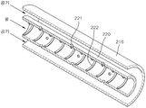
도 2는 본 발명에 따른 기포 발생 장치에서 이중 배출관의 개략 투영 사시도이고, 도 3은 본 발명에 따른 기포 발생 장치에서 이중 배출관의 개략 단면도이다.2 is a schematic perspective view of a double discharge pipe in a bubble generating device according to the present invention, and FIG. 3 is a schematic cross-sectional view of a double discharge pipe in a bubble generating device according to the present invention.
이중 배출관(200)은 이중 배관 구조로서, 펌프(P)를 통해 유입되는 유 체와 공기를 이용하여 기포를 생성하여 배출한다. 이를 위해서, 이중 배 출관(200)은 도 2 및 도 3에 도시된 바와 같이, 내부 배출관(220)과 외부 배출 관(210)을 포함한다.The
내부 배출관(220)은 펌프(P)로부터 유입되는 유체, 즉, 물을 배출시킨다. 내부 배출관(220)의 내면은 스파이럴 구조로서, 돌출된 나선형의 가이드(222)가 형성되어 펌프(P)로부터 유입되는 유체가 나선형으로 회전하도록, 즉, 와류가 발생되도록 한다. 또한, 내부 배출관(220)에는 외부 배출관(210)으로 유입되는 공기가 내부 배출관(220) 내로 배출되도록 공기 유입홀(221)이 형성된다.The
도 4는 본 발명의 변형예에 따른 기포 발생 장치에서 공기 유입홀이 형성된 이중 배출관의 개략 단면도이다.4 is a schematic cross-sectional view of a double discharge pipe having an air inlet hole formed in a bubble generating device according to a modification of the present invention.
공기 유입홀(221)은 외부 배출관(210)과 내부 배출관(220) 사이로 주입 된 공기가 내부 배출관(220)으로 유입될 수 있도록 한다. 이를 위해서, 공기 유입홀(221)은 내부 배출관(220)에 다수개가 형성되며, 도 3을 참조하면, 유체 가 흐르는 방향으로 공기가 경사지게 내부 배출관(220)으로 유입될 수 있도록 측벽이 경사지게 형성된다. 이 경우, 공기 유입홀(221)에서 배출되는 나선 방 향의 공기의 힘이 더해져 가이드(222)에 의해 발생되는 와류를 더욱 크게 발생 시킬 수 있다. 또한, 도 4에 도시된 바와 같이, 공기 유입홀(221)을 유선형으로 형성하여 내부 배출관(220)으로 유입되는 공기의 방향이 물이 이동하는 방향과 더욱 평행이 되도록 할 수도 있다. 여기서, 공기 유입홀(221)은 외부 배출관(210)에서 내부 배출관(220) 방향으로 갈수록 지름이 감소하도록 형성되는 것이 바람직하다. 이 경우, 공기 유입홀(221)을 통해 유입되는 공기의 속도가 증가하여 기포를 더욱 쉽게 발생시킬 수 있다. 한편, 공기 유입홀(221)은 다수개가 상기 가이드(222)에 대응되도록 내부 배출관(220)에 나선형태로 배열될 수도 있다.The
외부 배출관(210)은 펌프(P)로부터 유입되는 공기를 배출시킨다. 외부 배출관(210)과 내부 배출관(220) 사이에 공기 통로가 형성되어 펌프(P)로부터 유입되는 공기가 이동한다. 여기서, 내부 배출관(220)의 유체가 외부 배출관 (210)으로 유출되지 않도록, 외부 배출관(210)으로 유입되는 공기의 압력은 내 부 배출관(220)으로 유입되는 유체의 압력보다 큰 것이 바람직하다.The
도 5는 본 발명의 변형예에 따른 기포 발생 장치에서 노즐 형태의 이중 배출관의 개략 사시도이다.5 is a schematic perspective view of a nozzle type double discharge pipe in a bubble generating device according to a modification of the present invention.
한편, 본 발명은 전술된 배출관의 길이를 길게 하여 기포를 발생 시킨다. 이에 따라, 배출관을 설치하기 어려울 수 있으므로, 본 발명은 배출관 자체를 나선형태로 말아서 배출관을 설치하기 쉽도록 하는 것이 효과적이다. 이는 도 5에 도시된 바와 같이, 중공의 하우징(H)을 구비하고, 중공의 하우징(H) 내에 이중의 배출관(200)이 코일 형태로 감긴 형태로 구현할 수도 있다. 이 경우, 해당 구조를 분리 가능한 노즐 형태로 구현할 수 있으며, 기존의 기포 발생 장치에 적용할 수 있다.On the other hand, the present invention generates air bubbles by increasing the length of the aforementioned discharge pipe. Accordingly, since it may be difficult to install the discharge pipe, the present invention is effective to make it easy to install the discharge pipe by rolling the discharge pipe itself in a spiral form. As shown in FIG. 5, a hollow housing H may be provided, and a
상술한 바와 같이, 본 발명은 이중 구조의 배출관을 구비하고 내부 배출관에는 유체를, 외부 배출관에는 공기를 주입하고 내부 배출관에 형성된 공기 유입홀을 통해 내부 배출관으로 공기가 유입되도록 하여 기포를 효율적으로 발생시킬 수 있다.As described above, the present invention is equipped with a discharge pipe having a dual structure, injects fluid into the internal discharge pipe, injects air into the external discharge pipe, and efficiently generates air bubbles by allowing air to flow into the internal discharge pipe through the air inlet hole formed in the internal discharge pipe. I can do it.
이상과 같이 본 발명에 대해서 예시한 도면을 참조로 하여 설명하였으나, 본 명세서에 개시된 실시 예와 도면에 의해 본 발명이 한정되는 것은 아니며, 본 발명의 기술사상의 범위 내에서 통상의 기술자에 의해 다양한 변형이 이루어질 수 있음은 자명하다. 아울러 앞서 본 발명의 실시 예를 설명하면서 본 발명의 구성에 따른 작용 효과를 명시적으로 기재하여 설명하지 않았을 지라도, 해당 구성에 의해 예측 가능한 효과 또한 인정되어야 함은 당연하다.As described above, the present invention has been described with reference to the exemplified drawings, but the present invention is not limited by the examples and drawings disclosed in the present specification, and can be varied by a person skilled in the art within the scope of the technical idea of the present invention. It is obvious that modifications can be made. In addition, although the operation and effect according to the configuration of the present invention has not been explicitly described while explaining the embodiments of the present invention, it is natural that the predictable effect by the configuration should also be recognized.
100: 유입관
200: 배출관
210: 외부 배출관
220: 내부 배출관
221: 공기 유입홀
222: 가이드
P: 펌프
100: inlet pipe 200: outlet pipe
210: external discharge pipe 220: internal discharge pipe
221: air inlet hole 222: guide
P: Pump
Claims (4)
상기 내부 배출관으로는 유체를 유입시키고, 상기 공간으로는 공기를 유입시키는 펌프를 포함하는 기포 발생 장치.
A double discharge pipe including a hollow external discharge pipe and an internal discharge pipe provided inside the external discharge pipe so that a space is formed between the external discharge pipe and a plurality of air inlet holes are spaced apart, and
A bubble generating device including a pump for introducing a fluid into the internal discharge pipe and introducing air into the space.
상기 내부 배출관의 내주연에 형성된 스파이럴 형태로 돌출된 가이드를 포함하는 기포 발생 장치.
According to claim 1,
A bubble generating device including a guide projecting in a spiral form formed on an inner periphery of the inner discharge pipe.
상기 공기 유입홀은 상기 유체가 흐르는 방향으로 경사지게 형성된 기포 발생 장치.
According to claim 2,
The air inlet hole is a bubble generating device formed inclined in the direction in which the fluid flows.
중공의 하우징을 더 포함하고,
상기 이중 배출관은 상기 하우징 내에 코일 형태로 감긴 기포 발생 장치.
??According to claim 3,
Further comprising a hollow housing,
The double discharge pipe is a bubble generating device wound in a coil form in the housing.
??
Priority Applications (1)
| Application Number | Priority Date | Filing Date | Title |
|---|---|---|---|
| KR1020180131450A KR20200048870A (en) | 2018-10-31 | 2018-10-31 | Bubble generator |
Applications Claiming Priority (1)
| Application Number | Priority Date | Filing Date | Title |
|---|---|---|---|
| KR1020180131450A KR20200048870A (en) | 2018-10-31 | 2018-10-31 | Bubble generator |
Publications (1)
| Publication Number | Publication Date |
|---|---|
| KR20200048870A true KR20200048870A (en) | 2020-05-08 |
Family
ID=70677763
Family Applications (1)
| Application Number | Title | Priority Date | Filing Date |
|---|---|---|---|
| KR1020180131450A KR20200048870A (en) | 2018-10-31 | 2018-10-31 | Bubble generator |
Country Status (1)
| Country | Link |
|---|---|
| KR (1) | KR20200048870A (en) |
Citations (1)
| Publication number | Priority date | Publication date | Assignee | Title |
|---|---|---|---|---|
| KR200440223Y1 (en) | 2006-12-08 | 2008-05-30 | 김신숙 | Micro Bubble Machine |
-
2018
- 2018-10-31 KR KR1020180131450A patent/KR20200048870A/en not_active IP Right Cessation
Patent Citations (1)
| Publication number | Priority date | Publication date | Assignee | Title |
|---|---|---|---|---|
| KR200440223Y1 (en) | 2006-12-08 | 2008-05-30 | 김신숙 | Micro Bubble Machine |
Similar Documents
| Publication | Publication Date | Title |
|---|---|---|
| US7997563B2 (en) | Micro-bubble generator, vortex breakdown nozzle for micro-bubble generator, vane swirler for micro-bubble generator, micro-bubble generating method, and micro-bubble applying device | |
| RU2013104946A (en) | THE COMBUSTION CHAMBER | |
| GB201302161D0 (en) | Microbubble-generating device | |
| CN103785311A (en) | Micro-nano bubble generating device | |
| RU2015101349A (en) | PLANT FOR TRANSFORMING A FLUID FLOW TO ENERGY | |
| KR20200048869A (en) | Bubble generator | |
| JP2018058038A (en) | Fine bubble generating device | |
| KR20200048870A (en) | Bubble generator | |
| JP6151555B2 (en) | Fluid suction mixing device | |
| KR102305212B1 (en) | Bubble generator | |
| CN104722222A (en) | Multi-point injection gas-liquid mixer | |
| JP5912347B2 (en) | Thrust booster | |
| KR101530609B1 (en) | Nano bubble device | |
| KR20190124435A (en) | Nano bubble generator | |
| JP6019418B1 (en) | Microbubble generator, microbubble generator and system | |
| JP5755410B2 (en) | Shower head without watering plate | |
| JP2017221919A (en) | Fine bubble generator, shower head and mixed phase fluid processing device | |
| KR20210096489A (en) | Microbubble generator | |
| RU2489597C1 (en) | Device for improvement of operating stability of radial-axial hydraulic turbine | |
| RU2014122392A (en) | MASS TRANSFER | |
| RU2231004C1 (en) | Rotary cavitation pump-heat generator | |
| KR101540158B1 (en) | Low noise injection apparatus for outlet pipe of vessel and vessel having the same | |
| JP5614696B1 (en) | Microbubble generator | |
| JP2013096318A (en) | Water stream cone body with built-in flow straightening device | |
| RU2007112900A (en) | METHOD FOR SPRAYING LIQUID FUEL AND DEVICE FOR ITS IMPLEMENTATION |
Legal Events
| Date | Code | Title | Description |
|---|---|---|---|
| AMND | Amendment | ||
| E601 | Decision to refuse application | ||
| AMND | Amendment | ||
| X601 | Decision of rejection after re-examination |