KR20200047257A - Device and a method for displaying aerial view images of a vehicle - Google Patents
Device and a method for displaying aerial view images of a vehicle Download PDFInfo
- Publication number
- KR20200047257A KR20200047257A KR1020190000657A KR20190000657A KR20200047257A KR 20200047257 A KR20200047257 A KR 20200047257A KR 1020190000657 A KR1020190000657 A KR 1020190000657A KR 20190000657 A KR20190000657 A KR 20190000657A KR 20200047257 A KR20200047257 A KR 20200047257A
- Authority
- KR
- South Korea
- Prior art keywords
- image
- vehicle
- captured
- around
- current
- Prior art date
Links
- 238000000034 method Methods 0.000 title claims abstract description 33
- 238000012545 processing Methods 0.000 claims abstract description 73
- 239000002131 composite material Substances 0.000 claims description 11
- 230000002194 synthesizing effect Effects 0.000 claims description 10
- 230000015572 biosynthetic process Effects 0.000 claims description 7
- 238000003786 synthesis reaction Methods 0.000 claims description 7
- 230000001360 synchronised effect Effects 0.000 claims description 6
- 239000013589 supplement Substances 0.000 claims description 4
- 238000003384 imaging method Methods 0.000 abstract description 6
- 230000008569 process Effects 0.000 abstract description 6
- 230000005540 biological transmission Effects 0.000 abstract description 5
- 230000001502 supplementing effect Effects 0.000 abstract description 3
- 238000010586 diagram Methods 0.000 description 14
- 238000004364 calculation method Methods 0.000 description 7
- 238000009825 accumulation Methods 0.000 description 5
- 238000006243 chemical reaction Methods 0.000 description 5
- 238000001514 detection method Methods 0.000 description 5
- 238000000605 extraction Methods 0.000 description 4
- 238000005516 engineering process Methods 0.000 description 3
- 230000006870 function Effects 0.000 description 3
- 230000002093 peripheral effect Effects 0.000 description 3
- 238000012937 correction Methods 0.000 description 2
- 238000003672 processing method Methods 0.000 description 2
- 230000004044 response Effects 0.000 description 2
- QNRATNLHPGXHMA-XZHTYLCXSA-N (r)-(6-ethoxyquinolin-4-yl)-[(2s,4s,5r)-5-ethyl-1-azabicyclo[2.2.2]octan-2-yl]methanol;hydrochloride Chemical compound Cl.C([C@H]([C@H](C1)CC)C2)CN1[C@@H]2[C@H](O)C1=CC=NC2=CC=C(OCC)C=C21 QNRATNLHPGXHMA-XZHTYLCXSA-N 0.000 description 1
- 230000001133 acceleration Effects 0.000 description 1
- 230000004913 activation Effects 0.000 description 1
- 230000008859 change Effects 0.000 description 1
- 238000007796 conventional method Methods 0.000 description 1
- 238000013461 design Methods 0.000 description 1
- 238000009434 installation Methods 0.000 description 1
- 239000004973 liquid crystal related substance Substances 0.000 description 1
- 230000004807 localization Effects 0.000 description 1
- 238000013507 mapping Methods 0.000 description 1
- 238000012986 modification Methods 0.000 description 1
- 230000004048 modification Effects 0.000 description 1
- 230000003287 optical effect Effects 0.000 description 1
- 238000005192 partition Methods 0.000 description 1
- 239000007787 solid Substances 0.000 description 1
- 238000009966 trimming Methods 0.000 description 1
Images


Classifications
-
- B—PERFORMING OPERATIONS; TRANSPORTING
- B60—VEHICLES IN GENERAL
- B60W—CONJOINT CONTROL OF VEHICLE SUB-UNITS OF DIFFERENT TYPE OR DIFFERENT FUNCTION; CONTROL SYSTEMS SPECIALLY ADAPTED FOR HYBRID VEHICLES; ROAD VEHICLE DRIVE CONTROL SYSTEMS FOR PURPOSES NOT RELATED TO THE CONTROL OF A PARTICULAR SUB-UNIT
- B60W50/00—Details of control systems for road vehicle drive control not related to the control of a particular sub-unit, e.g. process diagnostic or vehicle driver interfaces
- B60W50/08—Interaction between the driver and the control system
- B60W50/14—Means for informing the driver, warning the driver or prompting a driver intervention
-
- B—PERFORMING OPERATIONS; TRANSPORTING
- B60—VEHICLES IN GENERAL
- B60K—ARRANGEMENT OR MOUNTING OF PROPULSION UNITS OR OF TRANSMISSIONS IN VEHICLES; ARRANGEMENT OR MOUNTING OF PLURAL DIVERSE PRIME-MOVERS IN VEHICLES; AUXILIARY DRIVES FOR VEHICLES; INSTRUMENTATION OR DASHBOARDS FOR VEHICLES; ARRANGEMENTS IN CONNECTION WITH COOLING, AIR INTAKE, GAS EXHAUST OR FUEL SUPPLY OF PROPULSION UNITS IN VEHICLES
- B60K35/00—Arrangement of adaptations of instruments
-
- B—PERFORMING OPERATIONS; TRANSPORTING
- B60—VEHICLES IN GENERAL
- B60R—VEHICLES, VEHICLE FITTINGS, OR VEHICLE PARTS, NOT OTHERWISE PROVIDED FOR
- B60R1/00—Optical viewing arrangements; Real-time viewing arrangements for drivers or passengers using optical image capturing systems, e.g. cameras or video systems specially adapted for use in or on vehicles
-
- B—PERFORMING OPERATIONS; TRANSPORTING
- B60—VEHICLES IN GENERAL
- B60W—CONJOINT CONTROL OF VEHICLE SUB-UNITS OF DIFFERENT TYPE OR DIFFERENT FUNCTION; CONTROL SYSTEMS SPECIALLY ADAPTED FOR HYBRID VEHICLES; ROAD VEHICLE DRIVE CONTROL SYSTEMS FOR PURPOSES NOT RELATED TO THE CONTROL OF A PARTICULAR SUB-UNIT
- B60W40/00—Estimation or calculation of non-directly measurable driving parameters for road vehicle drive control systems not related to the control of a particular sub unit, e.g. by using mathematical models
- B60W40/02—Estimation or calculation of non-directly measurable driving parameters for road vehicle drive control systems not related to the control of a particular sub unit, e.g. by using mathematical models related to ambient conditions
-
- H—ELECTRICITY
- H04—ELECTRIC COMMUNICATION TECHNIQUE
- H04N—PICTORIAL COMMUNICATION, e.g. TELEVISION
- H04N23/00—Cameras or camera modules comprising electronic image sensors; Control thereof
- H04N23/57—Mechanical or electrical details of cameras or camera modules specially adapted for being embedded in other devices
-
- H—ELECTRICITY
- H04—ELECTRIC COMMUNICATION TECHNIQUE
- H04N—PICTORIAL COMMUNICATION, e.g. TELEVISION
- H04N23/00—Cameras or camera modules comprising electronic image sensors; Control thereof
- H04N23/90—Arrangement of cameras or camera modules, e.g. multiple cameras in TV studios or sports stadiums
-
- H04N5/2257—
-
- H04N5/247—
-
- H—ELECTRICITY
- H04—ELECTRIC COMMUNICATION TECHNIQUE
- H04N—PICTORIAL COMMUNICATION, e.g. TELEVISION
- H04N7/00—Television systems
- H04N7/18—Closed-circuit television [CCTV] systems, i.e. systems in which the video signal is not broadcast
- H04N7/181—Closed-circuit television [CCTV] systems, i.e. systems in which the video signal is not broadcast for receiving images from a plurality of remote sources
-
- B—PERFORMING OPERATIONS; TRANSPORTING
- B60—VEHICLES IN GENERAL
- B60W—CONJOINT CONTROL OF VEHICLE SUB-UNITS OF DIFFERENT TYPE OR DIFFERENT FUNCTION; CONTROL SYSTEMS SPECIALLY ADAPTED FOR HYBRID VEHICLES; ROAD VEHICLE DRIVE CONTROL SYSTEMS FOR PURPOSES NOT RELATED TO THE CONTROL OF A PARTICULAR SUB-UNIT
- B60W50/00—Details of control systems for road vehicle drive control not related to the control of a particular sub-unit, e.g. process diagnostic or vehicle driver interfaces
- B60W50/08—Interaction between the driver and the control system
- B60W50/14—Means for informing the driver, warning the driver or prompting a driver intervention
- B60W2050/146—Display means
-
- B—PERFORMING OPERATIONS; TRANSPORTING
- B60—VEHICLES IN GENERAL
- B60W—CONJOINT CONTROL OF VEHICLE SUB-UNITS OF DIFFERENT TYPE OR DIFFERENT FUNCTION; CONTROL SYSTEMS SPECIALLY ADAPTED FOR HYBRID VEHICLES; ROAD VEHICLE DRIVE CONTROL SYSTEMS FOR PURPOSES NOT RELATED TO THE CONTROL OF A PARTICULAR SUB-UNIT
- B60W2420/00—Indexing codes relating to the type of sensors based on the principle of their operation
- B60W2420/40—Photo or light sensitive means, e.g. infrared sensors
- B60W2420/403—Image sensing, e.g. optical camera
-
- B—PERFORMING OPERATIONS; TRANSPORTING
- B60—VEHICLES IN GENERAL
- B60W—CONJOINT CONTROL OF VEHICLE SUB-UNITS OF DIFFERENT TYPE OR DIFFERENT FUNCTION; CONTROL SYSTEMS SPECIALLY ADAPTED FOR HYBRID VEHICLES; ROAD VEHICLE DRIVE CONTROL SYSTEMS FOR PURPOSES NOT RELATED TO THE CONTROL OF A PARTICULAR SUB-UNIT
- B60W2420/00—Indexing codes relating to the type of sensors based on the principle of their operation
- B60W2420/42—Image sensing, e.g. optical camera
-
- B—PERFORMING OPERATIONS; TRANSPORTING
- B60—VEHICLES IN GENERAL
- B60W—CONJOINT CONTROL OF VEHICLE SUB-UNITS OF DIFFERENT TYPE OR DIFFERENT FUNCTION; CONTROL SYSTEMS SPECIALLY ADAPTED FOR HYBRID VEHICLES; ROAD VEHICLE DRIVE CONTROL SYSTEMS FOR PURPOSES NOT RELATED TO THE CONTROL OF A PARTICULAR SUB-UNIT
- B60W2520/00—Input parameters relating to overall vehicle dynamics
- B60W2520/06—Direction of travel
-
- B—PERFORMING OPERATIONS; TRANSPORTING
- B60—VEHICLES IN GENERAL
- B60W—CONJOINT CONTROL OF VEHICLE SUB-UNITS OF DIFFERENT TYPE OR DIFFERENT FUNCTION; CONTROL SYSTEMS SPECIALLY ADAPTED FOR HYBRID VEHICLES; ROAD VEHICLE DRIVE CONTROL SYSTEMS FOR PURPOSES NOT RELATED TO THE CONTROL OF A PARTICULAR SUB-UNIT
- B60W2530/00—Input parameters relating to vehicle conditions or values, not covered by groups B60W2510/00 or B60W2520/00
- B60W2530/18—Distance travelled
Abstract
Description
본 발명은 자동차 등의 차량의 주위 영상을 표시하는 차량 주위 영상 표시 시스템 및 그 표시 방법에 관한 것으로, 보다 상세하게는, 차량 주위를 촬영하는 카메라로부터 얻어진 영상에 근거하여, 자기차량 및 그 주변의 부감 영상을 합성하여 표시할 때에, 자기차량의 이동에 맞추어, 자기차량의 직하를 포함한 주위 영상을 사각 없이 표시 가능한 차량 주위 영상 표시 시스템 및 차량 주위 영상 표시 방법에 관한 것이다.The present invention relates to a vehicle surrounding image display system for displaying a surrounding image of a vehicle such as an automobile, and a display method thereof, and more specifically, based on an image obtained from a camera shooting around the vehicle, the subject vehicle and its surroundings. The present invention relates to an image display system around a vehicle and a method of displaying an image around a vehicle that can display surrounding images including a direct view of the subject vehicle without blind spots in accordance with the movement of the subject vehicle when synthesizing and displaying the overlooking image.
차량을 운전하는 운전자가 직접 볼 수 있는 범위는 한정되어 있다. 특히, 차량 후방은 일반적인 룸미러나 도어미러를 이용하여도 운전석으로부터는 볼 수 없는 사각이 되는 개소가 다수 존재한다. 예를 들면, 차량 후방을 보았을 경우 운전자의 시야의 일부는 트렁크나 후부 필러로 차단된다. 그래서, 종래, 차량의 주위 상황을 촬영하는 카메라를 차량에 탑재하여, 촬영한 영상을 디스플레이에 표시시키는 것으로, 운전자의 주위 확인을 보조하는 장치가 제안되고 있다.The range that can be directly seen by the driver driving the vehicle is limited. In particular, there are a number of places in the rear of the vehicle that become a blind spot that cannot be seen from the driver's seat even when using a normal room mirror or door mirror. For example, when looking at the rear of the vehicle, part of the driver's field of view is blocked by the trunk or rear pillars. Thus, conventionally, a device that assists the driver in checking the surroundings of a vehicle has been proposed by mounting a camera that photographs the surroundings of the vehicle on a vehicle and displaying the captured image on a display.
예를 들면, 특허 문헌 1에 개시된 기술에서는, 차량의 주변을 촬영하는 복수의 카메라로 취득한 촬영 영상을 가공하여, 운전자가 백미러를 개재하여 보이는 위치에 배치된 표시 수단의 표시면에, 차량 주위의 사각이 되는 영역의 영상도 포함한 합성 영상을 표시시키는 것을 제안하고 있다. 또한, 특허 문헌 2에 개시된 기술에서는, 촬영한 영상으로부터 검출된 주차 구획선이 불완전한 경우에, 촬영 수단에 의해 과거에 촬영된 과거 영상을 중첩하여 표시하는 기술이 개시되어 있다.For example, in the technology disclosed in
그러나, 특허 문헌 1의 기술에서는, 차량의 하부나 외주부 부근의 상황을 반영할 수 없기 때문에, 타이어와 장애물 등과의 위치 확인이나, 타이어와 홈 등과의 위치 관계를 영상으로 확인할 수 없었다. 또한, 특허 문헌 2의 기술은, 영상이 선명하지 않은 부분을 과거에 촬영한 영상에 옮겨놓기 때문에, 현재의 상황을 반영할 수 없었다.However, in the technique of
본 발명은 상기 종래의 문제점을 감안하여 이루어진 것이며, 본 발명의 목적은 자기차량에 의해 사각이 되는 차량 하부나 외주부 부근의 상황이 가시화된 차량 주위 영상을 표시함과 함께, 차량의 이동에 맞추어 사각이 없는 차량 주위 영상의 표시 범위를 최적화하는 차량 주위 영상 표시 시스템을 제공하는 것에 있다.The present invention has been made in view of the above-mentioned conventional problems, and an object of the present invention is to display an image around a vehicle in which a situation near a lower portion or an outer circumference of a vehicle becomes a blind spot by a magnetic vehicle, and a blind spot according to the movement of the vehicle. An object of the present invention is to provide a video display system around a vehicle that optimizes the display range of a video around a vehicle without this.
상기 목적을 달성하기 위해서 이루어진 본 발명의 하나의 양태에 의한 차량 주위 영상 표시 시스템은 차량의 진행에 동기된 차량 주위 영상을 표시시키는 차량 주위 영상 표시 시스템이며, 상기 영상 표시 시스템은 차량에 배치되어 상기 차량의 주위를 촬영하는 촬영 수단과, 상기 촬영 수단에 의해 촬영된 영상을 보존하는 영상 기억 수단과, 상기 촬영된 영상을 영상처리 하는 영상 처리 수단과, 영상 처리된 영상을 표시하는 영상 표시 수단을 구비하고, 상기 영상 처리 수단은 상기 촬영 수단에 의해 촬영된 현재의 영상의 사각 부분을, 현재보다 이전에 촬영된 영상으로부터 생성된 이력 영상으로 보완한 차량 주위 영상을 생성하고, 상기 영상 표시 수단은 상기 생성된 차량 주위 영상에 상기 영상 기억 수단에 보존된 자기차량의 투과 영상을 중첩하여 표시하는 것을 특징으로 한다.The vehicle surrounding image display system according to one aspect of the present invention made to achieve the above object is a vehicle surrounding image display system that displays a vehicle surrounding image synchronized with the progress of the vehicle, and the image display system is disposed on the vehicle and A photographing means for photographing the surroundings of the vehicle, image storage means for preserving the image photographed by the photographing means, image processing means for image processing the photographed image, and image display means for displaying the image processed image The image processing means generates an image around the vehicle that supplements a rectangular portion of the current image photographed by the photographing means with a history image generated from an image previously taken, and the image display means The transmitted image of the own vehicle stored in the image storage means is superimposed on the generated vehicle surrounding image. Characterized in that it displays.
상기 촬영 수단은 자기차량의 후방 또는 전방 주변을 촬영 가능한 1개 이상의 광각 카메라를 포함하고, 상기 광각 카메라에 의해 촬영된 영상을, 프레임 단위로 상기 영상 처리 수단에 송신하고, 상기 영상 처리 수단은 수신된 영상을 연속하는 프레임 단위의 부감 영상으로 변환하고, 상기 변환된 부감 영상을 합성하여 이력 영상을 생성할 수 있다.The photographing means includes one or more wide-angle cameras capable of photographing the rear or front periphery of the subject vehicle, and transmits an image photographed by the wide-angle camera to the image processing means in units of frames, and the image processing means is received The converted image may be converted into a sub-frame image in a continuous frame unit, and the converted sub-frame image may be synthesized to generate a history image.
상기 영상 표시 시스템은 상기 촬영된 영상에 근거하여, 자기차량의 방향, 이동 방향, 및 이동 거리를 산출하는 차량 위치 검출 수단을 더 구비하고, 상기 영상 처리 수단은 상기 차량의 이동 거리가 소정의 이동 거리에 도달할 때마다, 상기 산출된 자기차량의 방향, 이동 방향, 및 이동 거리에 근거하여, 상기 촬영된 현재의 영상과 상기 현재보다 이전에 촬영된 영상과의 합성 위치를 프레임마다 조정하여, 상기 이력 영상을 갱신할 수 있다.The image display system further includes vehicle position detection means for calculating a direction, a moving direction, and a moving distance of the subject vehicle based on the captured image, wherein the moving distance of the vehicle is a predetermined movement. Each time a distance is reached, based on the calculated direction, moving direction, and moving distance of the subject vehicle, a composite position of the captured current image and an image taken before the current is adjusted for each frame, The history image can be updated.
상기 영상 처리 수단은 상기 차량의 진행에 맞추어, 상기 촬영된 현재의 영상과, 상기 생성된 이력 영상을 조합하여, 상기 촬영된 현재의 영상에 상기 이력 영상과 다른 부분이 있는 경우, 상기 다른 부분의 영상을 강조 표시한 차량 주위 영상을 생성할 수 있다.The image processing means combines the captured current image with the generated historical image in accordance with the progress of the vehicle, and when there is a portion different from the historical image in the captured current image, It is possible to generate an image around a vehicle in which the image is highlighted.
상기 영상 처리 수단은 상기 차량의 진행에 맞추어, 상기 자차 위치 추정 수단으로 산출된 자기차량의 방향, 이동 방향, 및 이동 거리에 근거하여, 합성되는 상기 촬영된 현재의 영상과 상기 현재보다 이전에 촬영된 영상을 크롭(crop) 하거나, 또는 영상 합성 위치를 설정할 수 있다.The image processing means, according to the progress of the vehicle, based on the direction, the moving direction, and the moving distance of the subject vehicle calculated by the own vehicle position estimation means, the captured current image to be synthesized and before the current shooting You can crop the image, or set the location for image synthesis.
상기 목적을 달성하기 위해서 이루어진 본 발명의 하나의 양태에 의한 차량 주위 영상 표시 방법은, 양쪽의 진행에 동기된 차량 주위 영상을 표시시키는 방법이며, 차량에 배치되어 상기 차량의 주변을 촬영하는 촬영 수단, 상기 촬영 수단에 의해 촬영된 영상을 보존하는 영상 기억 수단, 상기 촬영된 영상을 영상처리 하는 영상 처리 수단, 및 상기 영상 처리된 영상을 표시하는 영상 표시 수단을 구비한 차량 주위 영상 표시 시스템에 있어서, 상기 영상 처리 수단이 상기 촬영 수단에 의해 촬영된 영상을 수신하여, 수신된 상기 영상을 연속하는 프레임 단위의 부감 영상으로 변환하고, 상기 변환된 부감 영상을 합성하여 이력 영상을 생성하는 스텝과, 상기 촬영 수단에 의해 촬영된 현재의 영상의 사각 부분을 상기 생성된 이력 영상으로 보완한 차량 주위 영상을 생성하는 스텝과, 상기 생성된 차량 주위 영상에 상기 영상 기억 수단에 보존된 자기차량의 투과 영상을 중첩하여 표시하는 스텝을 가지는 것을 특징으로 한다.A vehicle surrounding image display method according to one aspect of the present invention made to achieve the above object is a method of displaying a vehicle surrounding image synchronized with the progress of both sides, and is a photographing means arranged on a vehicle to photograph the surrounding of the vehicle In the image display system around the vehicle having an image storage means for preserving the image photographed by the photographing means, image processing means for image processing the photographed image, and image display means for displaying the image processed image A step in which the image processing means receives the image photographed by the photographing means, converts the received image into a sub-frame image in a continuous frame unit, and synthesizes the converted sub-image to generate a history image; A vehicle main that complements the rectangular portion of the current image photographed by the photographing means with the generated history image. And a step of generating the above image and superimposing and displaying the transmitted image of the own vehicle stored in the image storage means on the generated image around the vehicle.
상기 이력 영상을 생성하는 스텝은 상기 연속하는 프레임 단위의 부감 영상으로부터 특징점을 추출하고, 상기 추출된 특징점이 일치하도록 합성 위치를 조정하는 스텝을 포함할 수 있다.The step of generating the history image may include a step of extracting a feature point from the successive frame-level subtraction image and adjusting a synthesis position to match the extracted feature point.
상기 차량 주위 영상 표시 방법은 상기 영상 처리 수단이 상기 촬영된 영상에 근거하여, 자기차량의 방향, 이동 방향, 및 이동 거리를 산출하는 스텝을 더 포함하고, 상기 이력 영상을 생성하는 스텝은 상기 산출된 차량의 이동 거리가 소정의 이동 거리에 도달할 때마다, 상기 산출된 자기차량의 방향, 이동 방향, 및 이동 거리에 근거하여, 상기 촬영된 현재의 영상과 상기 현재보다 이전에 촬영된 영상과의 합성 위치를 프레임마다 조정하여, 상기 이력 영상을 갱신하는 스텝을 포함할 수 있다.The image display method around the vehicle further includes a step of the image processing means calculating a direction, a moving direction, and a moving distance of the subject vehicle based on the photographed image, and the step of generating the history image is the calculating Whenever the moving distance of the vehicle reaches a predetermined moving distance, based on the calculated direction, moving direction, and moving distance of the subject vehicle, the captured current image and an image taken before the current It may include the step of adjusting the composite position of each frame, to update the history image.
상기 투과 영상을 중첩하여 표시하는 스텝은 상기 차량의 진행에 맞추어, 상기 촬영된 현재의 영상과, 상기 생성된 이력 영상을 조합하고, 상기 촬영된 현재의 영상에 상기 이력 영상과 다른 부분이 있는 경우, 상기 다른 부분의 영상을 강조하여 표시시키는 스텝을 포함할 수 있다.The step of superimposing and displaying the transmitted image is a combination of the captured current image and the generated historical image in accordance with the progress of the vehicle, and when the captured current image has a different portion from the historical image And, it may include a step of highlighting and displaying the image of the other portion.
상기 차량 주위 영상을 생성하는 스텝은 상기 차량의 진행에 맞추어, 상기 산출된 자기차량의 방향, 이동 방향, 및 이동 거리에 근거하여, 합성되는 상기 촬영된 현재의 영상과 상기 현재보다 이전에 촬영된 영상을 크롭(crop) 하거나, 또는 영상 합성 위치를 설정하는 스텝을 포함할 수 있다.The step of generating an image around the vehicle is based on the calculated direction of the vehicle, the moving direction, and the moving distance, in accordance with the progress of the vehicle, the captured current image being synthesized and previously taken before the current It may include a step of cropping an image or setting an image synthesis location.
본 발명에 의하면, 자기차량에 의해 사각이 되는 차량 하부나 외주부 부근의 상황이 가시화된 차량 주위 영상을 표시할 수 있고, 더욱이 차량의 진행에 동기하여 표시 범위가 최적화된 사각이 없는 차량 주위 영상을 표시할 수 있다.According to the present invention, it is possible to display an image around a vehicle in which the situation near the lower part of the vehicle or the outer periphery becomes a blind spot by the subject vehicle, and furthermore, an image of a vehicle without a blind spot in which the display range is optimized in synchronization with the progress of the vehicle Can be displayed.
또한, 차량의 이동 거리가 소정의 이동 거리에 도달할 때마다 산출된 자기차량의 방향, 이동 방향, 및 이동 거리에 근거하여, 촬영된 현재의 영상과 현재보다 이전에 촬영된 영상과의 합성 위치를 프레임마다 조정하여, 이력 영상을 갱신하고 있기 때문에, 취득한 프레임 모두를 사용하여 합성 영상을 생성하는 경우에 비하여, 처리량이 적게 되는 것으로 영상 처리의 부하가 경감됨과 함께, 프레임 합성시에 발생하는 미미한 오차의 축적, 즉, 누적 오차를 저감 할 수 있다.In addition, the composite position of the captured current image and the previously captured image based on the direction, moving direction, and moving distance of the subject vehicle calculated whenever the moving distance of the vehicle reaches a predetermined moving distance. Is adjusted for each frame, and since the historical image is updated, the processing load is reduced and the processing load is reduced as compared to the case where a synthesized image is generated using all the acquired frames. Accumulation of errors, that is, accumulation errors can be reduced.
도 1은 본 발명의 일실시 형태에 의한 차량 주위 영상 표시 시스템의 전체 구성을 도시하는 도면이다.
도 2는 본 실시 형태에 의한 주위 영상 표시 시스템의 카메라 촬영 범위의 일례를 도시하는 도면이다.
도 3은 본 실시 형태에 의한 차량 주위 영상 표시 시스템의 기능 구성의 일례를 도시하는 블럭도이다.
도 4는 본 실시 형태에 의한 양 주위 영상 표시 시스템이 차량 주위 영상을 취득하여 표시할 때까지의 영상 처리 순서를 도시하는 플로차트이다.
도 5는 본 실시 형태의 차량 주위 영상 표시 시스템에 의한 영상 처리의 각 단계에 있어서의 처리 영상의 일례를 도시하는 도면이다.
도 6은 본 실시 형태의 차량 주위 영상 표시 시스템에 의해 표시되는 차량 주위 영상의 일례를 도시하는 도면이다.
도 7은 본 실시 형태에 있어서, 영상 처리의 추가적인 처리에 의해 생성된 영상예를 도시하는 도면이다.
도 8은 본 실시 형태에 있어서, 영상 처리의 또 다른 추가적인 처리에 의해 생성된 영상예를 도시하는 도면이다.
도 9는 본 실시 형태에 의한 차량 주위 영상 표시 시스템의 다른 영상 처리예를 도시하는 개념도이다.
도 10은 본 실시 형태에 의한 차량 주위 영상 표시 시스템의 또 다른 영상 처리예를 도시하는 개념도이다.1 is a view showing the overall configuration of a video display system around a vehicle according to an embodiment of the present invention.
2 is a diagram showing an example of a camera shooting range of the surrounding video display system according to the present embodiment.
3 is a block diagram showing an example of a functional configuration of a video display system around a vehicle according to the present embodiment.
Fig. 4 is a flowchart showing an image processing procedure until both surrounding video display systems according to the present embodiment acquire and display surrounding video of the vehicle.
5 is a diagram showing an example of the processed video at each stage of video processing by the video display system around the vehicle of the present embodiment.
6 is a view showing an example of a vehicle surroundings image displayed by the vehicle surroundings video display system of the present embodiment.
7 is a diagram showing an example of an image generated by additional processing of image processing in the present embodiment.
8 is a diagram showing an example of an image generated by another additional process of image processing in the present embodiment.
9 is a conceptual diagram showing another example of image processing of the video display system around the vehicle according to the present embodiment.
10 is a conceptual diagram showing still another image processing example of the video display system around the vehicle according to the present embodiment.
이하, 본 발명을 실시하기 위한 형태의 구체적인 예를, 도면을 참조하면서 상세하게 설명한다.Hereinafter, specific examples of the embodiments for carrying out the present invention will be described in detail with reference to the drawings.
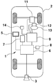
도 1은 본 발명의 일실시 형태에 의한 차량 주위 영상 표시 시스템의 전체 구성을 도시하는 도면이다. 도 1에 도시하는 바와 같이, 본 실시 형태에 의한 차량 주위 영상 표시 시스템(1)은 차량(2)의 후부에 설치된 카메라(촬영 수단, 3), 차내에 배치된 액정 디스플레이 등으로 이루어지는 차재 모니터 장치(영상 표시 수단, 5), 영상 처리 ECU(영상 처리 수단 6), 차량 정보 DB(7), 주행 영상 DB(영상 기억 수단 8), 및 차량 ECU(9) 등으로 구성된다. 또한, 차량(2)의 앞 부분에도 카메라를 설치하여, 전방 및 후방의 주위 영상을 촬영하는 구성으로 하는 것도 가능하다. 또한, 차량(2)의 좌우에도 도시하지 않은 카메라를 설치하여, 4개의 카메라를 이용하여 종래의 어라운드 뷰 영상을 포함한 표시를 행하는 것도 가능하다. 이하에서는, 설명을 간단하게 하기 위해, 후부에 설치된 예에 대하여 설명한다.1 is a view showing the overall configuration of a video display system around a vehicle according to an embodiment of the present invention. As shown in Fig. 1, the vehicle surrounding
도 2는 본 실시 형태에 의한 주위 영상 표시 시스템의 카메라 촬영 범위의 일례를 도시하는 도면이다. 본 실시 형태에 있어서, 카메라(3)은 예를 들면 CCD나 CMOS 등의 고체 촬영 소자를 이용한 것이며, 도 2에 도시하는 바와 같이, 차량(2)의 후방 중앙 부근에 장착되고, 촬영 방향을 수평보다 하부를 향하여 설치된다. 그리고, 차량(2)의 진행 방향(즉, 이동 방향)에 따라 차량 후방을 촬영하고, 촬영한 영상(이하, 촬영 영상이라고 한다)을 영상 신호로서 출력한다. 카메라로부터 출력된 영상 신호는 후술하는 영상 처리 수단에 의해 영상 데이터로 변환되고, 소정의 영상 처리를 거쳐, 차량 주위 영상, 예를 들면 부감 영상으로서, 차재 모니터 장치(5)에 표시된다. 또한 본 실시 형태에 있어서, 카메라(3)는 광각렌즈를 구비하고, 좌우 110도~140도 정도의 범위를 촬영할 수 있는 것이 사용되지만, 이것에 한정되지 않는다.2 is a diagram showing an example of a camera shooting range of the surrounding video display system according to the present embodiment. In the present embodiment, the
차재 모니터 장치(5)는 차량(2) 실내의 센터 콘솔 또는 패널 면에 비치할 수 있고, 카메라(3)로 촬영된 영상으로부터 생성된 합성 영상 등을 표시한다. 또한, 차재 모니터 장치(5)는 내비게이션 장치에 사용하는 것과 겸용하여도 된다.The in-
영상 처리 ECU(Electronic Control Unit, 6)는 카메라(3)로 촬영된 영상의 영상 데이터에 대해, 각종 영상 처리를 행하는 전자 제어 유닛이다. 본 실시 형태에 있어서, 영상 처리 ECU(6)가 행하는 제 1의 영상 처리는 촬영 영상의 영상 데이터에 대해, 좌표 변화를 행하여 부감 영상을 생성하고, 프레임 단위로 주행 영상 DB(8)에 보존한다. 제 2의 영상 처리는 프레임 마다의 영상 데이터로부터 차량(2)이 이동하는 주로(走路)의 구획선이나 표시 등을 포함한 도로상의 특징이 되는 부분을 검출하고, 검출된 구획선이나 표시 등을 이용하여 특징점 추출 및 일치점 탐색에 의한 시계열 영상의 합성 처리를 행한다. 더욱이 제 3의 영상 처리로서, 자기차량의 진행(즉, 이동)에 동기하여, 자기차량에 의한 사각 영역을 보완한 부감 영상을 생성하고, 이것에 자기차량의 투과 영상을 중첩한 영상 데이터를 생성한다. 또한, 영상 처리 ECU(6)의 상세한 구성에 대해서는 후술한다.The image processing ECU (Electronic Control Unit) 6 is an electronic control unit that performs various image processing on image data of an image captured by the
차량 정보 DB(데이타베이스, 7)는 차량(2)이나 카메라(3)에 관한 각종 파라미터가 기억된 기억 수단이다. 차량 정보 DB(7)에는 예를 들면, 차량(2)의 최소 선회 반경, 차폭, 트레드 길이, 타이어 반경 등의 차량 모델에 관한 정보나, 카메라(3)의 내부 파라미터, 광축 방향, 화각, 설치 위치 등의 카메라(3)의 설계 값에 관한 정보가 기억되어 있다.The vehicle information DB (database 7) is a storage means in which various parameters relating to the
주행 영상 DB(8)는 카메라(3)에 의해 촬영된 영상의 영상 데이터가 촬영시의 카메라(3)의 카메라 위치, 촬영 방향각, 차량 위치, 차량의 방향 등의 부가 정보에 관련되고, 프레임 단위로 보존되는 기억 수단이다. 또한, 본 실시 형태에 있어서, 주행 영상 DB(8)의 기억장치에는 SSD(솔리드 스테이트 드라이브)가 사용되지만, 자기 디스크, 메모리 카드, DVD 등을 외부 기억장치로서 사용할 수도 있다.The driving
차량 ECU(9)는 엔진, 변속기, 브레이크 등의 작동을 제어하는 차량(2)의 전자 제어 유닛이다. 차량 ECU(9)에는 차속 센서(11), 자이로 센서(12), 조타각 센서(13), 시프트 위치 검출 센서(14) 등의 각종 센서가 접속된다. 영상 처리 ECU(6)는 이러한 센서의 출력 값으로부터, 차량(2)의 차속, 가속도, 조타각이나, 차량의 방향, 이동 거리 등을 산출하는 것이 가능하다.The
다음에, 본 실시 형태에 의한 차량 주위 영상 표시 시스템(1)의 기능 구성에 대해, 도 3을 참조하면서 설명한다. 도 3은 본 실시 형태에 의한 차량 주위 영상 표시 시스템의 기능 구성의 일례를 도시하는 블럭도이다.Next, a functional configuration of the
도 3에 도시하는 바와 같이, 본 실시 형태에 의한 차량 주위 영상 표시 시스템(1)은 영상 처리 ECU(6)로 실행되는 차량 주위 영상 생성 프로그램에 의해 실현되는 기능 수단을 기본으로 하여 구성되고, 각 기능 수단에 대해서 소정의 주변기기가 접속되어 있다.As shown in Fig. 3, the vehicle surroundings
영상 처리 ECU(6)는 영상 입력부(61), 차량 신호 입력부(62), 연산부(63), 영상 출력부(64)를 포함한다.The
영상 입력부(61)는 카메라(3)로 촬영된 차량 주위 영상의 영상 데이터를 취득하기 위한 입력 인터페이스이다. 영상 입력부(61)는 A/D 변환기를 포함하고, 카메라(3)로부터 출력된 영상 신호를 디지털 신호로 변환하여 프레임 단위의 영상 데이터를 생성한다. 또한, 카메라(3)가 디지털 영상 신호를 출력하는 타입의 경우는, A/D 변환기는 생략 가능하다. 영상 입력부(61)는 영상을 연속 영상(동영상)으로서 취득하는 것도 가능하지만, 본 실시 형태에서는 차량의 이동에 응하여, 카메라(3)의 촬영 범위에 상당하는 이동 거리마다, 정지 화면 단위, 즉, 프레임 단위로 영상을 취득한다. 또한, 영상을 취득하는 간격은 인접하는 프레임을 합하여 붙일때에 풀칠하기 위해 남겨 두는 부분(糊代)을 얻을 수 있도록, 이동 방향의 영상 길이(도 2의 부호 L로 나타내는 촬영 범위) 이하인 것이 바람직하다.The
차량 신호 입력부(62)는 각종 센서에서 검출된 차량의 이동에 관련된 데이터(이하, 이동량 데이터라고 한다)를 취득하기 위한 인터페이스이다. 차량 신호 입력부(62)는 이동량 데이터를 예를 들면, 차내 LAN을 개재하여, 차량 ECU(9)로부터 취득한다.The vehicle
연산부(63)는 CPU, RAM, ROM 등을 구비한 주지의 마이크로 콘트롤러로 구성된다. 또한, ROM에는 후술하는 영상 처리 프로그램, 그 외, 차재 모니터 장치(5) 등의 제어에 필요한 각종 프로그램 등이 격납되어 있다. 또한, RAM은 CPU로 연산된 각종 데이터를 일시적으로 기억해 두는 메모리이다.The
연산부(63)는 영상 입력부(61)로부터 영상 데이터를 프레임 단위로 취득할 때 마다, 후술하는 각 기능부를 기능시켜, 금회 취득한 촬영 영상의 영상 데이터와, 금회보다 이전에 취득한 영상에 근거하는 이력 영상의 영상 데이터를 합성한 차량 주변 영상 데이터를 생성하고, 생성된 차량 주변 영상 데이터를 영상 출력부(64)에 출력한다.Whenever the image data is acquired from the
영상 출력부(64)는 연산부(63)로부터 출력된 차량 주변 영상 데이터를 차량의 이동에 맞추어, 순서대로 차재 모니터 장치(5)에 출력한다. 이것에 의해, 차내의 드라이버 등의 승무원은 차재 모니터 장치(5)에 표시되는 차량 주변 영상을 볼 수 있다.The
연산부(63)는 차량 주위 영상 생성 프로그램의 실행에 의해 실현되는 기능부로서, 영상 변환부(63a), 특징점 추출부(63b), 자차 위치 추정부(63c), 이력 영상 축적부(63d), 이동 거리 추정부(63e), 방향키 각 추정부(63f), 차량 이동량 연산부(63g), 영상 합성부(63h), 출력 영상 생성부(63i)를 포함하여, 주행 영상 DB(8), 차량 ECU(9)를 개재하여 각 주변기기로부터 취득한 각종 정보에 근거하여, 차재 모니터 장치에 촬영 영상(도 5 참조)을 표시하도록 제어한다.The
영상 변환부(63a)는 영상 입력부(61)로부터 프레임 단위의 영상 데이터를 수신하면, 수신된 영상 데이터에 대해, 광각 촬영에 기인하는 영상 일그러짐의 보정을 행한다. 그 후, 일그러짐 보정을 행한 영상 데이터에 대해 좌표 변화를 행하고, 부감 영상의 영상 데이터를 생성하는 처리를 행한다. 그리고, 영상 변환부(63a)는 생성된 부감 영상의 영상 데이터를 프레임 단위로 주행 영상 DB(8)에 보존한다. 이것에 의해 과거의 촬영 영상의 영상 데이터가 축적된다. 여기서, 부감 영상으로 변환하는 기술은, 예를 들면, 일본국 특개 평10-211849호 공보에 개시되어 있는 종래 기술을 이용할 수 있다.When the
특징점 추출부(63b)는 부감 영상으로 변환된 현재의 영상, 또는 주행 영상 DB(8)에 축적된 과거의 촬영 영상(축적된 부감 영상)에 대해, 대상으로 하는 프레임 단위의 영상(이하, 프레임 영상이라고 한다)의 화면 내에 존재하는 특징점을 추출한다. 특징점은 프레임 화면이 이동했을 때에 추종 가능한 점이며, 일반적으로는 각 프레임 영상 내에 있어서 세로 방향, 가로 방향 모두 휘도 차이가 있는 점이 특징점으로서 추출된다. 즉, 특징점은 엣지 처리 등의 영상 처리에 의해 검출 가능하고, 특징점의 검출 방법으로서 다양한 수법(SIFT, A-KAZE, SURF 등)이 공지의 처리 방법으로서 제안되고 있다. 이러한 처리 방법을 이용하여 특징점을 추출한다.The feature
자차 위치 추정부(63c)는 부감 영상으로 변환된 현재의 프레임 영상의 특징점과, 주행 영상 DB(8)에 축적된 이전의 프레임 영상(축적된 부감 영상)과의 특징점을 조합(照合)하는 것으로, 자차 위치를 추정한다. 구체적으로는, 주행 영상 DB(8)로부터 직전의 프레임에 대응하는 영상 데이터를 읽어내고, 읽어낸 직전의 프레임 영상 중의 특징점과 현재의 프레임 영상 중의 특징점 중에서 특징점을 선별한다. 그리고, 선별된 특징점의 프레임 영상 내에서의 위치를 추정하고, 그 프레임 영상 내 위치의 추정값을 중심으로서 선별된 특징점을 영상 내에서 검색한다. 이 검색에 의해, 직전의 위치로부터 상정되는 영상 내 위치와 실제로 검출된 영상 내 위치와의 차이를 검출한다. 그 후, 자차 위치 추정부(63c)는 프레임 영상 내의 특징점 위치와 자차 위치의 직전의 위치로부터 검출되는 특징점 위치의 차이로부터, 자차 위치의 추정값을 보정하여 자차 위치를 산출한다. 이러한 처리에는, SLAM(Simultaneous Localization And Mapping) 기술을 이용한다.The host
이력 영상 축적부(63d)는 부감 영상으로 변환된 각 프레임의 영상 데이터를 차량 이동량 정보에 근거하여, 인접하는 프레임 단위로, 특징점 검출부(31)에 의해 얻어진 특징점과 자차 위치 추정부(63c)에서 추정된 자차 위치에 관한 정보를 관련지어, 이력 영상 데이터로서 주행 영상 DB(8)에 보존한다.The historical
이동 거리 추정부(63e)는 차량 신호 입력부(62)가 차량의 이동량 데이터를 취득하면, 취득한 이동량 데이터에 포함되는 이동 거리에 근거하고, 다음에 영상 입력부(61)가 촬영 영상을 취득하는 타이밍을 추정한다. 즉, 차량의 이동 거리가 카메라(3)에서 촬영되는 프레임 사이즈(도 2에 도시하는 촬영 범위의 L)에 상당하는 이동 거리에 도달하였는지 아닌지를 판정한다. 이동 거리 추정부(63e)는 차량의 이동 거리가 미리 설정된 값(예를 들면, 촬영 범위의 L의 길이의 90%)에 도달하였다고 판단하면, 영상 입력부(61)에 대해, 그 시점에서 촬영된 프레임 영상을 취득하는 신호(이하, 영상 취득 신호라고 한다)를 발신한다. 영상 취득 신호는 방향키 각 추정부(63f)에도 송신된다.When the vehicle
방향키 각 추정부(63f)는 차량 신호 입력부(62)가 차량의 이동량 데이터를 취득하면, 취득한 이동량 데이터에 포함되는 방향키 각 데이터를 판별하고, 이동 거리 추정부(63e)로부터 영상 취득 신호를 수신하면, 영상 입력부(61)가 촬영 영상을 취득하는 시점에 있어서, 차량의 방향키 각을 차량 이동량 연산부(63g)에 송신한다.When the vehicle
차량 이동량 연산부(63g)는 이동 거리 추정부(63e), 방향키 각 추정부(63f)에 의해 취득된 현재를 포함한 소정의 시간 기간의 이동 거리 및 방향키 각의 데이터에 근거하여, 영상 입력부(61)가 현재를 포함한 소정의 시간 기간에 차량이 어떻게 이동했는지를 산출한다. 산출된 각 데이터는 영상 입력부(61)가 취득한 프레임 단위의 영상 데이터에 관련지어 주행 영상 DB(8)에 보존되고, 해당 프레임 영상을 크롭(crop)(또는, 트리밍) 하는 범위를 조정할 경우에 이용된다.The vehicle movement
영상 합성부(63h)는 영상 입력부(61)가 촬영 영상의 영상 데이터를 취득하면, 최신의 촬영 영상을 실제 영상으로 한다. 또한, 현재 이전의 소정의 시간 기간에 취득된 시계열의 프레임 영상 데이터를 주행 영상 DB(8)로부터 읽어내고, 차량의 이동에 맞추어 배열한다. 차량 이동량 연산부(63g)가 산출한 차량의 이동 내용의 산출 결과에 근거하여, 현재의 차량의 촬영 영상의 위치와, 주행 영상 DB(8)로부터 읽어 내어진 이전의 프레임 영상의 위치를 각각의 프레임에서 추출된 특징점이 매칭되도록 합성 위치를 조정하여, 이력 영상 데이터를 생성하고, 실제 영상의 사각이 되는 부분이 이력 영상으로 보완되도록, 실제 영상의 영상 데이터에 이력 영상의 영상 데이터를 합성하여, 차량 주위 영상의 영상 데이터를 생성한다.When the
출력 영상 생성부(63i)는 생성된 차량 주위 영상의 영상 데이터에 자기차량의 투과 영상 데이터를 중첩하여, 순서대로, 영상 출력부(64)에 출력한다. 더욱이, 출력 영상 생성부(63i)는 다른 센서에서 검출된 물체나 현재의 촬영 영상중에 이력 영상과의 차이점이 검출되면, 미리 설정된 강조 처리를 행하고, 보완된 영상 데이터를 영상 출력부(64)에 전송한다.The output
영상 출력부(64)는 출력 영상 생성부(63i)로부터 수신한 차량 주변 영상의 영상 데이터를 차재 모니터 장치(5)에 표시한다.The
다음에, 도 4 및 도 5를 참조하여, 본 발명의 일실시 형태에 의한 차량 주위 영상 표시 시스템의 동작에 대해 설명한다. 도 4는 본 실시 형태에 의한 차량 주위 영상 표시 시스템이, 차량 주위 영상을 취득하여 표시할 때까지의 영상 처리 순서를 도시하는 플로차트(flow chart)이다. 도 5는 본 실시 형태의 차량 주위 영상 표시 시스템에 의한 영상 처리의 각 단계에 있어서 처리 영상의 일례를 도시하는 도면이다. 본 실시 형태에서는, 차량을 후퇴(백) 시키는 경우에 대해 설명한다.Next, with reference to Figs. 4 and 5, the operation of the video display system around the vehicle according to an embodiment of the present invention will be described. 4 is a flow chart showing a video processing procedure until the vehicle surroundings video display system according to the present embodiment acquires and displays surroundings images. Fig. 5 is a diagram showing an example of the processed video in each step of the video processing by the video display system around the vehicle of the present embodiment. In this embodiment, a case in which the vehicle is retracted (back) will be described.
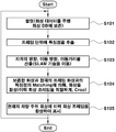
도 4에 도시하는 바와 같이, 본 시스템이 기동되면, 카메라(3)에 의해 차량 후방의 노면 및 그 주위가 촬영되고, 영상 처리 ECU(6)는 각 기능 수단을 제어하고, 이하에 나타내는 일련의 영상 처리를 실행한다.As shown in Fig. 4, when the present system is activated, the road surface and the surroundings of the rear of the vehicle are photographed by the
우선, 영상 처리 ECU(6)는 카메라(3)로 촬영된 차량 후방의 주위 영상의 영상 데이터를, 영상 입력부(61)를 개재하여, 차량의 이동에 동기된 프레임 단위로 취득하여, 주행 영상 DB(8)에 보존한다(스텝 S101). 이때, 주행 영상 DB(8)에 보존되는 프레임 영상의 영상 데이터는, 위에서 설명한 바와 같이 영상 변환부(63a)에 의해 프레임 단위로 부감 영상으로 변환된 영상 데이터이다.First, the
구체적으로, 카메라(3)로부터 출력되는 원영상(카메라 영상)은 예를 들면, 도 5의 영상(a)에 도시하는 바와 같이, 차량 후부의 상부에 배치된 카메라(3)(광각 카메라)에 의해, 도로에 그어진 백선(구획선이나 표시) 및 그 주위를 촬영한 영상이므로, 자기차량(즉, 카메라(3))과 백선의 위치와의 거리 등에 응해, 본래 상태보다 백선 등이 비뚤어져 표시된다. 그래서, 영상 변환부(63a)에 의해, 도 5의 영상(b)에 도시하는 바와 같이, 광각 촬영에 기인하는 영상 일그러짐 보정을 행한 후에, 좌표 변화되어, 도 5의 영상(c)에 도시하는 부감 영상의 영상 데이터가 생성된다.Specifically, the original image (camera image) output from the
다음에, 차량의 이동에 동기하여, 순차 프레임 단위로 취득된 부감 영상의 영상 데이터는 특징점 추출부(63b)에 의해, 그 직전의 프레임의 영상 데이터와의 사이에서, 일치점 검색에 이용하기 위한 특징점이 추출된다. 예를 들면, 도 5의 영상(d)에 도시하는 바와 같이, 시각(t)에 취득된 프레임 N의 영상에서 검출된 마름모꼴 형태의 마크와, 그 직후의 시각(t+1)에 취득된 프레임(N+1)의 영상에서 검출된 마름모꼴 형태의 마크가 특징점으로서 추출된다(스텝 S102).Next, in synchronism with the movement of the vehicle, the video data of the subtracted image acquired in units of sequential frames is used by the feature
그 후, 자차 위치 추정부(63c)에 의해, 추출된 특징점을 이용하여, 도 5의 영상(e)에 도시하는 바와 같이, 프레임(N) 및 프레임(N+1)의 2 영상간의 일치점이 탐색된다. 또한, 자차 위치 추정부(63c)는 일치점 탐색에 의해 선별된 특징점의 각 프레임 영상 내에서의 위치를 조합(照合)하여, 2 영상간의 차이를 검출한다. 자차 위치 추정부(63c)는 특징점 위치의 차이로부터, 자차의 방향, 이동 방향, 및 이동 거리를 산출한다(스텝 S103). 이러한 처리에는, 위에서 설명한 바와 같이 SLAM 기술이 이용된다. SLAM에 관해서는 여러가지 알고리즘이 발표되어 있고, Mono-SLAM이나 PTAM 등이 있다.Thereafter, by the own
다음에, 영상 합성부(63h)는 선택된 특징점의 위치 등에 기초하여, 도 5의 영상(f)에 도시하는 바와 같이, 불연속점이 적은 영상 경계를 설정하고, 주행 영상 DB(8)에 보존된 직전의 프레임 N의 영상 데이터와, 현재의 차량 주위를 촬영한 영상 데이터의 프레임(N+1)과의 특징점이 매칭되도록 합성 위치를 조정하고, 도 5의 영상(g)에 도시하는 바와 같이, 영상을 합성한다(스텝 S104). 마찬가지의 순서로, 직전의 프레임 N의 영상 데이터와 그 전의 프레임(N-1)의 영상 데이터를 합성하여, 복수의 프레임이 합성된 이력 영상의 영상 데이터를 생성한다. 또한, 영상 합성부(63h)는 이러한 영상을 합성할 때에, 차량 이동량 연산부(63g)로 산출된 이동량에 근거하여, 도 5의 영상(h)에 도시하는 바와 같이, 이력 영상의 프레임 범위를 적정하게 크롭하는 등의 처리를 행하여, 합성되는 영상을 정형하여도 된다.Next, the
그 후, 출력 영상 생성부(63i)는 현재 차량의 차량 주위 영상과 이력 영상을 합성한 차량 주위 영상에, 도 5의 영상(i)에 도시하는 바와 같이, 자기차량의 투과 영상이 중첩된 영상을 차재 모니터 장치(5)에 표시시킨다(스텝 S105).Thereafter, the output
도 6은 본 실시 형태의 차량 주위 영상 표시 시스템에 의해 표시되는 차량 주위 영상의 일례를 도시하는 도면이다. 상술한 동작에 의해, 본 시스템 기동 후, 차재 모니터 장치(5)에는 차량의 이동에 동기하여 생성된 이력 영상에 의해, 현재의 촬영 영상의 사각 부분이 보완된 영상이 표시된다. 즉, 도 6의 시각(t)에서 차량이 후퇴를 시작했을 때의 영상(A)에 대해, 그 후의 시각(t+i1) 및 시각(t+i2)의 영상(B) 및 (C)에는, 각각의 이전에 촬영된 영상으로부터 생성된 이력 영상에서, 현재의 촬영 영상의 사각 부분이 보완되어 표시된다. 또한, 차재 모니터 장치(5)에 표시되는 영상 범위는 기동 후, 자차의 현재 위치가 표시 화면의 중앙에 배치되도록 조정된다.6 is a view showing an example of a vehicle surroundings image displayed by the vehicle surroundings video display system of the present embodiment. By the above-described operation, after the system is started, the vehicle-mounted
이하, 본 실시 형태의 차량 주위 영상 표시 시스템에 의한 영상 처리의 다른 예에 대해 설명한다.Hereinafter, another example of the video processing by the video display system around the vehicle of the present embodiment will be described.
도 7은 본 실시 형태에 있어서, 영상 처리의 추가적인 처리에 의해 생성된 영상예를 도시하는 도면이다. 도 7에 도시하는 영상예는, 현재의 촬영 영상과 이력 영상을 합성할 때에, 연산부(63)에 포함되는 소정의 기능부(도시하지 않음)에서, 현재의 촬영 영상과 이력 영상을 조합하여, 현재의 촬영 영상중에 이력 영상에는 존재하지 않는 상위 부분이 있는 경우, 소정 방식의 영상 인식에 의해, 검출된 상위 부분이 장애물인지 아닌지를 판단한다. 그리고, 현재의 촬영 영상중에 장애물이 존재하고, 과거에 촬영된 영상에는 장애물이 없는 경우, 출력 영상 생성부(63i)는 이 장애물을 강조 표시한 영상 데이터를 생성한다. 이것에 의해, 차재 모니터 장치(5)에는, 장애물이 강조 표시되므로, 운전자의 주의를 환기하여, 운전 미스를 저감하는 것이 가능하게 된다.7 is a diagram showing an example of an image generated by additional processing of image processing in the present embodiment. In the video example shown in FIG. 7, when synthesizing the current photographed image and the historical image, a predetermined functional unit (not shown) included in the
도 8은 본 실시 형태에 있어서, 영상 처리의 또 다른 추가적인 처리에 의해 생성된 영상예를 도시하는 도면이다. 도 8에 도시하는 영상예는 차량에 구비된 다른 센서에서 접근하는 이동 물체가 검출되었을 경우, 출력 영상 생성부(63i)는 검출된 정보에 근거하여, 현재의 촬영 영상에 사각 부분을 보완한 이력 영상과 함께, 영상 처리 ECU(6)에 구비된 소정의 기능부(도시하지 않음)에서 산출한 이동 물체의 예측 진로를 중첩하여 표시하는 형태로 차량 주위 영상을 생성한다. 이것에 의해, 운전자에게 이동 물체에 대한 주의를 환기하는 것이 가능하게 된다.8 is a diagram showing an example of an image generated by another additional process of image processing in the present embodiment. In the example of the image shown in FIG. 8, when a moving object approaching from another sensor provided in the vehicle is detected, the output
이상, 본 발명의 일실시 형태에 의한 차량 주위 영상 표시 시스템에 있어서 영상 처리의 순서를, 차량을 후퇴(백) 시키는 경우에 대해 설명했지만, 본 발명은 차량을 전진시키는 경우에도, 마찬가지의 순서로 실시 가능하다.In the above, in the video display system around the vehicle according to the embodiment of the present invention, the procedure of image processing has been described in the case where the vehicle is retracted (back). It is possible.
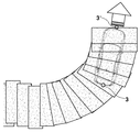
도 9는 본 실시 형태에 의한 차량 주위 영상 표시 시스템의 다른 영상 처리예를 도시하는 개념도이다. 도 9에 도시하는 영상 처리예는 차량의 앞부분에도 카메라(3')가 설치되고, 차량이 전진하는 경우의 차량 주위의 이력 영상이 생성되어 가는 경위를 나타낸다. 이 경우도 도 4에 도시하는 영상 처리의 순서에 따라, 차량의 진행(즉, 이동)에 맞추어, 프레임 단위의 이력 영상을 생성하여, 현재의 차량 주위의 촬영 영상을 이력 영상으로 보완하면서 차량 주위 영상을 생성하는 것으로, 차량 하부를 포함한 사각 부분이 보완된 차량 주위 영상을 표시시키는 것이 가능해진다.9 is a conceptual diagram showing another example of image processing of the video display system around the vehicle according to the present embodiment. In the image processing example shown in FIG. 9, a
도 10은 본 실시 형태에 의한 차량 주위 영상 표시 시스템의 또 다른 영상 처리예를 도시하는 개념도이다. 도 10에 도시하는 영상 처리예는 차량의 앞부분 및 후부에 설치된 카메라로 촬영된 영상을 이용하여, 차량 주위 영상을 생성하는 경우에, 차재 모니터 장치에 표시되는 차량 주위 영상의 예를, 동작 개시부터의 시간 경과에 맞추어 나타내는 도면이다. 차량 주위 영상의 생성은 상술한 순서와 마찬가지이므로 생략한다.10 is a conceptual diagram showing still another image processing example of the video display system around the vehicle according to the present embodiment. The image processing example shown in FIG. 10 is an example of an image around a vehicle displayed on the vehicle-mounted monitor device when an image around the vehicle is generated by using images captured by cameras installed at the front and rear parts of the vehicle, from the start of operation. It is a figure showing according to the passage of time. Generation of the image around the vehicle is omitted because it is the same as the above-described procedure.
이상에서 설명한 바와 같이, 본 발명에 의한 차량 주위 영상 표시 시스템은 차량의 진행에 동기하여, 사각 부분의 영상이 차례차례 가시화, 갱신되는 것으로, 최종적으로 사각이 없는 차량 주위 영상 표시가 가능하다. 이것에 의해, 리얼 타임의 영상을 표시하는 통상의 차량 주위 영상과, 가시화 및 갱신되는 사각의 영상(사각 영상은, 순서대로 생성 및 합성된다)을 위화감 없이 확인할 수 있다. 즉, 차량 하부의 통상 보이지 않는 지면의 영상 및 장애물의 위치를 영상으로 확인할 수 있다. 특히, 차량의 진행 방향(즉, 이동 방향)에 동기하여, 사각이 없는 영상이 생성되어 가므로, 위화감이 발생하지 않는다.As described above, the image display system around the vehicle according to the present invention is synchronized with the progress of the vehicle, and the image of the blind spot is sequentially visualized and updated, and finally, the image around the vehicle without the blind spot can be displayed. Thereby, a normal vehicle surrounding image displaying a real-time image and a rectangular image visualized and updated (square images are sequentially generated and synthesized) can be confirmed without discomfort. That is, it is possible to check the image of the ground and the position of obstacles that are not normally visible under the vehicle with the image. In particular, an image without a blind spot is generated in synchronization with the vehicle moving direction (that is, the moving direction), so that a sense of discomfort does not occur.
또한, 차량 전후의 카메라 영상을 사용하는 것으로, 사각이 없는 유사적인 차량 주위 영상을 생성할 수 있다. 전진, 후진 어느 진행 방향으로 나아가도, 사각의 영상이 생성 가능하고, 또한, 전후의 영상을 합성하는 것으로, 2개의 카메라로 유사적으로 차량 주위 영상을 생성할 수 있다.In addition, by using camera images before and after the vehicle, it is possible to generate similar images around the vehicle without a blind spot. Moving forward or backward in any direction of travel, a rectangular image can be generated, and by combining the images before and after, it is possible to similarly generate images around the vehicle with two cameras.
주변 영상을 넓게 촬영하여, 촬영 영상의 일부를 이용하여 표시 영상을 생성하므로, 핸들의 조타각을 크게 조작한 경우도, 사각을 빠짐없이 생성할 수 있으므로, 편리성이 높다. 화면 모두를 처리하는 경우에 비해, 필요한 부분 영상을 사용하여 처리를 행하므로, 처리 부하를 경감할 수 있다.Since the surrounding image is photographed wide and a display image is generated using a part of the captured image, even when the steering angle of the handle is largely manipulated, a square can be generated without fail, so convenience is high. Compared to the case where all screens are processed, processing is performed using the necessary partial images, so that the processing load can be reduced.
본 발명에 의한 차량 주위 영상 표시 시스템은 핸들의 조타각을 크게 자르면, 사각 영상을 생성하기 위해서 필요한 영상 범위가 넓어지기 때문에, 이력 영상을 이용하여, 사각을 합성하기 위해서 필요한 범위보다 조금 넓은 범위를 크롭(Crop)하여, 합성 영상을 생성한 후, 사각 영상을 생성한다. 이것에 의해, 조타각을 크게 자르는 것으로, 표시되는 범위가 직전에 표시하고 있던 범위보다 부분적으로 넓어진 경우에도, 영상이 빠짐없이 표시가 가능하게 된다.In the image display system around the vehicle according to the present invention, when the steering angle of the steering wheel is largely cut, a range of images required to generate a square image is widened, so a range that is slightly wider than a range required to synthesize a square using a history image is used. After cropping, a composite image is generated, and then a square image is generated. As a result, by greatly cutting the steering angle, even if the displayed range is partially wider than the previously displayed range, the video can be displayed without missing.
주차장 등에서, 과거에 촬영한 영상과 현재의 영상을 조합하여, 사각 생성 영상 내에 다른 부분이 있으면, 그 장소를 강조 표시한다. 이것에 의해, 익숙해진 장소에서는 운전시에 주의가 산만해지지만, 과거와 다른 부분을 강조 표시하는 것으로, 운전 미스를 저감시킬 수 있다.In a parking lot, etc., the image captured in the past and the current image are combined, and if there is another part in the square generated image, the place is highlighted. As a result, attention is distracted at the time of driving in a familiar place, but driving errors can be reduced by highlighting different parts from the past.
촬영 영상 내의 동체 검출 결과(속도, 방향 등)로부터, 사각 내에 들어갈 가능성이 있는 물체는 진로 예상도를 표시한다. 사각 표시 부분은 과거 영상을 이용하고 있기 때문에, 이동체가 사각 내에 비집고 들어가는 경우는, 이동체의 위치를 리얼 타임으로 표시할 수 없지만, 예측 진로를 표시하는 것으로, 이동체에 대한 주의 환기가 가능 해진다.From the results of the detection of the body in the captured image (speed, direction, etc.), objects that are likely to fall within the blind spot indicate the predicted course. Since the square display portion uses the past image, when the moving object is squeezed into the square, the position of the moving object cannot be displayed in real time, but by displaying the predicted path, attention can be paid to the moving object.
이상, 본 발명의 실시 형태에 대하여 도면을 참조하면서 상세하게 설명했지만, 본 발명은 상술한 실시 형태에 한정되는 것은 아니고, 본 발명의 기술적 범위로부터 일탈하지 않는 범위 내에서 다양하게 변경 실시하는 것이 가능하다.The embodiments of the present invention have been described in detail with reference to the drawings, but the present invention is not limited to the above-described embodiments, and various modifications can be made without departing from the technical scope of the present invention. Do.
1 : 차량 주위 영상 표시 시스템 2 : 차량
3, 3': 카메라 5 : 차재 모니터 장치
6 : 영상 처리 ECU 7 : 차량 정보 DB
8 : 주행 영상 DB 9 : 차량 ECU
11 : 차속 센서 12 : 자이로 센서
13 : 조타각 센서 14 : 시프트 위치 검출 센서
61 : 영상 입력부 62 : 차량 신호 입력부
63 : 연산부 63a : 영상 변환부
63b : 특징점 추출부 63c : 자차 위치 추정부
63d : 이력 영상 축적부 63e : 이동 거리 추정부
63f : 방향키 각 추정부 63g : 차량 이동량 연산부
63h : 영상 합성부 63i : 출력 영상 생성부
64 : 영상 출력부1: Video display system around the vehicle 2: Vehicle
3, 3 ': Camera 5: Vehicle monitor device
6: Image processing ECU 7: Vehicle information DB
8: Driving image DB 9: Vehicle ECU
11: vehicle speed sensor 12: gyro sensor
13: steering angle sensor 14: shift position detection sensor
61: video input unit 62: vehicle signal input unit
63:
63b: Feature
63d: history
63f: Direction key
63h:
64: video output
Claims (10)
상기 차량 주위 영상 표시 시스템은,
차량에 배치되어 상기 차량의 주변을 촬영하는 촬영 수단과,
상기 촬영 수단에 의해 촬영된 영상을 보존하는 영상 기억 수단과,
상기 촬영된 영상을 영상 처리하는 영상 처리 수단과,
상기 영상 처리된 영상을 표시하는 영상 표시 수단을 구비하고,
상기 영상 처리 수단은 상기 촬영 수단에 의해 촬영된 현재의 영상의 사각 부분을, 현재보다 이전에 촬영된 영상으로부터 생성된 이력 영상으로 보완한 차량 주위 영상을 생성하고,
상기 영상 표시 수단은 상기 생성된 차량 주위 영상에 상기 영상 기억 수단에 보존된 자기차량의 투과 영상을 중첩하여 표시하는 것을 특징으로 하는 차량 주위 영상 표시 시스템.
It is an image display system around the vehicle that displays the image around the vehicle synchronized with the progress of the vehicle,
The video display system around the vehicle,
A photographing means disposed on a vehicle to photograph the surroundings of the vehicle;
Image storage means for preserving the image captured by said photographing means;
Image processing means for image processing the photographed image;
And image display means for displaying the image processed image,
The image processing means generates an image around the vehicle that supplements a rectangular portion of the current image photographed by the photographing means with a history image generated from an image previously photographed, and
The image display means superimposes and displays the transmitted image of the own vehicle stored in the image storage means on the generated vehicle surrounding image.
상기 촬영 수단은 자기차량의 후방 또는 전방 주변을 촬영 가능한 1개 이상의 카메라를 포함하고, 상기 카메라에 의해 촬영된 영상을 상기 영상 처리 수단에 송신하고,
상기 영상 처리 수단은 수신한 상기 영상을 연속하는 프레임 단위의 부감 영상으로 변환하고, 상기 변환된 부감 영상을 합성하여 이력 영상을 생성하는 것을 특징으로 하는 차량 주위 영상 표시 시스템.
According to claim 1,
The photographing means includes one or more cameras capable of photographing the rear or front periphery of the subject vehicle, and transmits an image photographed by the camera to the image processing means,
The image processing means converts the received image into a continuous sub-frame image, and synthesizes the converted sub-image to generate a history image.
상기 차량 주위 영상 표시 시스템은 상기 촬영된 영상에 근거하여, 자기차량의 방향, 이동 방향, 및 이동 거리를 산출하는 자차 위치 추정 수단을 더욱이 구비하고,
상기 영상 처리 수단은 상기 차량의 이동 거리가 소정의 이동 거리에 도달할 때 마다, 상기 산출된 자기차량의 방향, 이동 방향, 및 이동 거리에 근거하여, 상기 촬영된 현재의 영상과 상기 현재보다 이전에 촬영된 영상과의 합성 위치를 프레임마다 조정하여, 상기 이력 영상을 갱신하는 것을 특징으로 하는 차량 주위 영상 표시 시스템.
According to claim 2,
The vehicle surrounding image display system further includes a host vehicle position estimation means for calculating a direction, a moving direction, and a moving distance of the subject vehicle based on the captured image,
The image processing means, whenever the moving distance of the vehicle reaches a predetermined moving distance, based on the calculated direction, moving direction, and moving distance of the subject vehicle, the captured current image and before the current The image display system around the vehicle, characterized in that by adjusting the composite position with the image captured in the image for each frame, the history image is updated.
상기 영상 처리 수단은 상기 차량의 진행에 맞추어, 상기 촬영된 현재의 영상과, 상기 생성된 이력 영상을 조합하여, 상기 촬영된 현재의 영상에 상기 이력 영상과 다른 부분이 있는 경우, 상기 다른 부분의 영상을 강조 표시한 차량 주위 영상을 생성하는 것을 특징으로 하는 차량 주위 영상 표시 시스템.
The method of claim 3,
The image processing means combines the captured current image with the generated historical image in accordance with the progress of the vehicle, and when there is a portion different from the historical image in the captured current image, A vehicle surrounding image display system, characterized by generating an image around the vehicle with the image highlighted.
상기 영상 처리 수단은 상기 차량의 진행에 맞추어, 상기 자차 위치 추정 수단에서 산출된 자기차량의 방향, 이동 방향, 및 이동 거리에 근거하여, 합성되는 상기 촬영된 현재의 영상과 상기 현재보다 이전에 촬영된 영상을 크롭(crop) 하거나, 또는 영상 합성 위치를 설정하는 것을 특징으로 하는 차량 주위 영상 표시 시스템.
The method of claim 3,
The image processing means, according to the progress of the vehicle, based on the direction, movement direction, and movement distance of the subject vehicle calculated by the host vehicle position estimation means, the captured current image to be synthesized and before the current image taken A video display system around a vehicle, characterized in that the cropped image is cropped or an image synthesis position is set.
차량에 배치되어 상기 차량의 주변을 촬영하는 촬영 수단, 상기 촬영 수단에 의해 촬영된 영상을 보존하는 영상 기억 수단, 상기 촬영된 영상을 영상 처리하는 영상 처리 수단, 및 상기 영상 처리된 영상을 표시하는 영상 표시 수단을 구비한 차량 주위 영상 표시 시스템에 있어서,
상기 영상 처리 수단이,
상기 촬영 수단에 의해 촬영된 영상을 수신하고, 수신한 상기 영상을 연속하는 프레임 단위의 부감 영상으로 변환하고, 상기 변환된 부감 영상을 합성하여 이력 영상을 생성하는 스텝과,
상기 촬영 수단에 의해 촬영된 현재의 영상의 사각 부분을 상기 생성된 이력 영상으로 보완한 차량 주위 영상을 생성하는 스텝과,
상기 생성된 차량 주위 영상에 상기 영상 기억 수단에 보존된 자기차량의 투과 영상을 중첩하여 표시하는 스텝을 가지는 것을 특징으로 하는 차량 주위 영상 표시 방법.
It is a method to display the image around the vehicle synchronized with the progress of the vehicle,
A photographing means arranged on a vehicle to photograph the periphery of the vehicle, image storage means for preserving the image captured by the photographing means, image processing means for image processing the captured image, and displaying the image processed image In the video display system around the vehicle having a video display means,
The image processing means,
Receiving an image photographed by the photographing means, converting the received image into a sub-frame image in a continuous frame, and synthesizing the converted sub-image to generate a history image;
A step of generating an image around the vehicle that supplements the rectangular portion of the current image photographed by the photographing means with the generated history image;
And superimposing and displaying the transmitted image of the own vehicle stored in the image storage means on the generated vehicle surrounding image.
상기 이력 영상을 생성하는 스텝은 상기 연속하는 프레임 단위의 부감 영상으로부터 특징점을 추출하고, 상기 추출된 특징점이 일치하도록 합성 위치를 조정하는 스텝을 포함하는 것을 특징으로 하는 차량 주위 영상 표시 방법.
The method of claim 6,
The step of generating the history image includes extracting a feature point from the sub-frame image of the continuous frame unit and adjusting a composite position to match the extracted feature point.
상기 차량 주위 영상 표시 방법은,
상기 영상 처리 수단이, 상기 촬영된 영상에 근거하여, 자기차량의 방향, 이동 방향, 및 이동 거리를 산출하는 스텝을 더 포함하고,
상기 이력 영상을 생성하는 스텝은, 상기 산출된 차량의 이동 거리가 소정의 이동 거리에 도달할 때마다, 상기 산출된 자기차량의 방향, 이동 방향, 및 이동 거리에 근거하여, 상기 촬영된 현재의 영상과 상기 현재보다 이전에 촬영된 영상과의 합성 위치를 프레임마다 조정하여, 상기 이력 영상을 갱신하는 스텝을 포함하는 것을 특징으로 하는 차량 주위 영상 표시 방법.
The method of claim 7,
The video display method around the vehicle,
The image processing means further includes a step of calculating a direction, a moving direction, and a moving distance of the subject vehicle based on the captured image,
The step of generating the history image is based on the calculated direction, moving direction, and moving distance of the subject vehicle whenever the calculated moving distance of the vehicle reaches a predetermined moving distance. And adjusting a composite position of an image and an image captured before the current for each frame to update the history image.
상기 투과 영상을 중첩하여 표시하는 스텝은 상기 차량의 진행에 맞추어, 상기 촬영된 현재의 영상과, 상기 생성된 이력 영상을 조합하고, 상기 촬영된 현재의 영상에 상기 이력 영상과 다른 부분이 있는 경우, 상기 다른 부분의 영상을 강조하여 표시시키는 스텝을 포함하는 것을 특징으로 하는 차량 주위 영상 표시 방법.
The method of claim 8,
The step of superimposing and displaying the transmitted image is a combination of the captured current image and the generated historical image in accordance with the progress of the vehicle, and when the captured current image has a different portion from the historical image And a step of emphasizing and displaying the image of the other part.
상기 차량 주위 영상을 생성하는 스텝은 상기 차량의 진행에 맞추어, 상기 산출된 자기차량의 방향, 이동 방향, 및 이동 거리에 근거하여, 합성되는 상기 촬영된 현재의 영상과 상기 현재보다 이전에 촬영된 영상을 크롭(crop) 하거나, 또는 영상 합성 위치를 설정하는 스텝을 포함하는 것을 특징으로 하는 차량 주위 영상 표시 방법.The method of claim 8,
The step of generating an image around the vehicle is based on the calculated direction of the vehicle, the moving direction, and the moving distance, in accordance with the progress of the vehicle, the captured current image being synthesized and previously taken before the current And cropping an image, or setting a location for synthesizing the image.
Applications Claiming Priority (2)
| Application Number | Priority Date | Filing Date | Title |
|---|---|---|---|
| JP2018201617A JP7426174B2 (en) | 2018-10-26 | 2018-10-26 | Vehicle surrounding image display system and vehicle surrounding image display method |
| JPJP-P-2018-201617 | 2018-10-26 |
Publications (1)
| Publication Number | Publication Date |
|---|---|
| KR20200047257A true KR20200047257A (en) | 2020-05-07 |
Family
ID=70388751
Family Applications (1)
| Application Number | Title | Priority Date | Filing Date |
|---|---|---|---|
| KR1020190000657A KR20200047257A (en) | 2018-10-26 | 2019-01-03 | Device and a method for displaying aerial view images of a vehicle |
Country Status (2)
| Country | Link |
|---|---|
| JP (1) | JP7426174B2 (en) |
| KR (1) | KR20200047257A (en) |
Families Citing this family (4)
| Publication number | Priority date | Publication date | Assignee | Title |
|---|---|---|---|---|
| TWI682361B (en) * | 2018-12-14 | 2020-01-11 | 財團法人工業技術研究院 | Method and system for road image reconstruction and vehicle positioning |
| JP7018923B2 (en) * | 2019-12-13 | 2022-02-14 | 本田技研工業株式会社 | Parking Assistance Equipment, Parking Assistance Methods and Programs |
| CN114333105B (en) * | 2020-09-30 | 2023-04-07 | 比亚迪股份有限公司 | Image processing method, apparatus, device, vehicle, and medium |
| CN113315961B (en) * | 2021-05-26 | 2023-04-25 | 合众新能源汽车股份有限公司 | Method and device for mapping transparent A-pillar image blocks |
Citations (2)
| Publication number | Priority date | Publication date | Assignee | Title |
|---|---|---|---|---|
| JP2006135797A (en) | 2004-11-08 | 2006-05-25 | Matsushita Electric Ind Co Ltd | Ambient status displaying device for vehicle |
| JP2006311299A (en) | 2005-04-28 | 2006-11-09 | Aisin Aw Co Ltd | Parking section monitoring device |
Family Cites Families (5)
| Publication number | Priority date | Publication date | Assignee | Title |
|---|---|---|---|---|
| JP3690150B2 (en) | 1998-12-16 | 2005-08-31 | 株式会社豊田自動織機 | BACKWARD SUPPORT DEVICE AND VEHICLE IN VEHICLE |
| JP2005001570A (en) | 2003-06-12 | 2005-01-06 | Equos Research Co Ltd | Parking support device |
| JP4687411B2 (en) | 2005-11-15 | 2011-05-25 | 株式会社デンソー | Vehicle peripheral image processing apparatus and program |
| JP2014036326A (en) | 2012-08-08 | 2014-02-24 | Honda Motor Co Ltd | Bird's eye image display device |
| WO2017130397A1 (en) | 2016-01-29 | 2017-08-03 | 富士通株式会社 | Position estimation device, position estimation method, and position estimation program |
-
2018
- 2018-10-26 JP JP2018201617A patent/JP7426174B2/en active Active
-
2019
- 2019-01-03 KR KR1020190000657A patent/KR20200047257A/en active Search and Examination
Patent Citations (2)
| Publication number | Priority date | Publication date | Assignee | Title |
|---|---|---|---|---|
| JP2006135797A (en) | 2004-11-08 | 2006-05-25 | Matsushita Electric Ind Co Ltd | Ambient status displaying device for vehicle |
| JP2006311299A (en) | 2005-04-28 | 2006-11-09 | Aisin Aw Co Ltd | Parking section monitoring device |
Also Published As
| Publication number | Publication date |
|---|---|
| JP7426174B2 (en) | 2024-02-01 |
| JP2020068499A (en) | 2020-04-30 |
Similar Documents
| Publication | Publication Date | Title |
|---|---|---|
| JP4807104B2 (en) | Vehicle surrounding monitoring system and image display method | |
| JP5099451B2 (en) | Vehicle periphery confirmation device | |
| JP4907883B2 (en) | Vehicle periphery image display device and vehicle periphery image display method | |
| EP2739050B1 (en) | Vehicle surroundings monitoring system | |
| US7212653B2 (en) | Image processing system for vehicle | |
| KR20200047257A (en) | Device and a method for displaying aerial view images of a vehicle | |
| US9418556B2 (en) | Apparatus and method for displaying a blind spot | |
| US8441536B2 (en) | Vehicle periphery displaying apparatus | |
| US20080198226A1 (en) | Image Processing Device | |
| JP4696691B2 (en) | Parking support method and parking support device | |
| JP2001218197A (en) | Device for displaying periphery of vehicle | |
| JP5516998B2 (en) | Image generation device | |
| JP2009083764A (en) | Driving assisting device, driving assisting method, and computer program | |
| JP6471522B2 (en) | Camera parameter adjustment device | |
| JP4797877B2 (en) | VEHICLE VIDEO DISPLAY DEVICE AND VEHICLE AROUND VIDEO DISPLAY METHOD | |
| JP7000383B2 (en) | Image processing device and image processing method | |
| JP2011155651A (en) | Apparatus and method for displaying vehicle perimeter image | |
| JP2007096496A (en) | Vehicle periphery display system | |
| KR20130065268A (en) | Apparatus and method for displaying blind spot | |
| JP5083137B2 (en) | Driving assistance device | |
| KR101709009B1 (en) | System and method for compensating distortion of around view | |
| CN114103812A (en) | Backing-up and warehousing guide system and method | |
| JP2007096497A (en) | Vehicle periphery display system | |
| WO2019026246A1 (en) | Vehicle periphery image display device and vehicle periphery image display method | |
| WO2020196676A1 (en) | Image processing device, vehicle control device, method, and program |
Legal Events
| Date | Code | Title | Description |
|---|---|---|---|
| A201 | Request for examination |