KR20200044401A - a office chair with massage function - Google Patents
a office chair with massage function Download PDFInfo
- Publication number
- KR20200044401A KR20200044401A KR1020180125115A KR20180125115A KR20200044401A KR 20200044401 A KR20200044401 A KR 20200044401A KR 1020180125115 A KR1020180125115 A KR 1020180125115A KR 20180125115 A KR20180125115 A KR 20180125115A KR 20200044401 A KR20200044401 A KR 20200044401A
- Authority
- KR
- South Korea
- Prior art keywords
- acupressure
- stopper
- support
- plate
- backrest
- Prior art date
Links
Images


Classifications
-
- A—HUMAN NECESSITIES
- A47—FURNITURE; DOMESTIC ARTICLES OR APPLIANCES; COFFEE MILLS; SPICE MILLS; SUCTION CLEANERS IN GENERAL
- A47C—CHAIRS; SOFAS; BEDS
- A47C7/00—Parts, details, or accessories of chairs or stools
- A47C7/62—Accessories for chairs
-
- A—HUMAN NECESSITIES
- A61—MEDICAL OR VETERINARY SCIENCE; HYGIENE
- A61H—PHYSICAL THERAPY APPARATUS, e.g. DEVICES FOR LOCATING OR STIMULATING REFLEX POINTS IN THE BODY; ARTIFICIAL RESPIRATION; MASSAGE; BATHING DEVICES FOR SPECIAL THERAPEUTIC OR HYGIENIC PURPOSES OR SPECIFIC PARTS OF THE BODY
- A61H15/00—Massage by means of rollers, balls, e.g. inflatable, chains, or roller chains
-
- A—HUMAN NECESSITIES
- A47—FURNITURE; DOMESTIC ARTICLES OR APPLIANCES; COFFEE MILLS; SPICE MILLS; SUCTION CLEANERS IN GENERAL
- A47C—CHAIRS; SOFAS; BEDS
- A47C9/00—Stools for specified purposes
- A47C9/002—Stools for specified purposes with exercising means or having special therapeutic or ergonomic effects
-
- A—HUMAN NECESSITIES
- A47—FURNITURE; DOMESTIC ARTICLES OR APPLIANCES; COFFEE MILLS; SPICE MILLS; SUCTION CLEANERS IN GENERAL
- A47C—CHAIRS; SOFAS; BEDS
- A47C7/00—Parts, details, or accessories of chairs or stools
- A47C7/002—Chair or stool bases
- A47C7/006—Chair or stool bases with castors
-
- A—HUMAN NECESSITIES
- A47—FURNITURE; DOMESTIC ARTICLES OR APPLIANCES; COFFEE MILLS; SPICE MILLS; SUCTION CLEANERS IN GENERAL
- A47C—CHAIRS; SOFAS; BEDS
- A47C7/00—Parts, details, or accessories of chairs or stools
- A47C7/36—Support for the head or the back
- A47C7/40—Support for the head or the back for the back
- A47C7/46—Support for the head or the back for the back with special, e.g. adjustable, lumbar region support profile; "Ackerblom" profile chairs
- A47C7/462—Support for the head or the back for the back with special, e.g. adjustable, lumbar region support profile; "Ackerblom" profile chairs adjustable by mechanical means
-
- A—HUMAN NECESSITIES
- A47—FURNITURE; DOMESTIC ARTICLES OR APPLIANCES; COFFEE MILLS; SPICE MILLS; SUCTION CLEANERS IN GENERAL
- A47C—CHAIRS; SOFAS; BEDS
- A47C7/00—Parts, details, or accessories of chairs or stools
- A47C7/54—Supports for the arms
-
- A—HUMAN NECESSITIES
- A47—FURNITURE; DOMESTIC ARTICLES OR APPLIANCES; COFFEE MILLS; SPICE MILLS; SUCTION CLEANERS IN GENERAL
- A47C—CHAIRS; SOFAS; BEDS
- A47C7/00—Parts, details, or accessories of chairs or stools
- A47C7/54—Supports for the arms
- A47C7/541—Supports for the arms of adjustable type
-
- A—HUMAN NECESSITIES
- A61—MEDICAL OR VETERINARY SCIENCE; HYGIENE
- A61H—PHYSICAL THERAPY APPARATUS, e.g. DEVICES FOR LOCATING OR STIMULATING REFLEX POINTS IN THE BODY; ARTIFICIAL RESPIRATION; MASSAGE; BATHING DEVICES FOR SPECIAL THERAPEUTIC OR HYGIENIC PURPOSES OR SPECIFIC PARTS OF THE BODY
- A61H15/00—Massage by means of rollers, balls, e.g. inflatable, chains, or roller chains
- A61H15/0092—Massage by means of rollers, balls, e.g. inflatable, chains, or roller chains hand-held
-
- A—HUMAN NECESSITIES
- A61—MEDICAL OR VETERINARY SCIENCE; HYGIENE
- A61H—PHYSICAL THERAPY APPARATUS, e.g. DEVICES FOR LOCATING OR STIMULATING REFLEX POINTS IN THE BODY; ARTIFICIAL RESPIRATION; MASSAGE; BATHING DEVICES FOR SPECIAL THERAPEUTIC OR HYGIENIC PURPOSES OR SPECIFIC PARTS OF THE BODY
- A61H39/00—Devices for locating or stimulating specific reflex points of the body for physical therapy, e.g. acupuncture
- A61H39/04—Devices for pressing such points, e.g. Shiatsu or Acupressure
-
- A—HUMAN NECESSITIES
- A61—MEDICAL OR VETERINARY SCIENCE; HYGIENE
- A61H—PHYSICAL THERAPY APPARATUS, e.g. DEVICES FOR LOCATING OR STIMULATING REFLEX POINTS IN THE BODY; ARTIFICIAL RESPIRATION; MASSAGE; BATHING DEVICES FOR SPECIAL THERAPEUTIC OR HYGIENIC PURPOSES OR SPECIFIC PARTS OF THE BODY
- A61H15/00—Massage by means of rollers, balls, e.g. inflatable, chains, or roller chains
- A61H2015/0007—Massage by means of rollers, balls, e.g. inflatable, chains, or roller chains with balls or rollers rotating about their own axis
- A61H2015/0028—Massage by means of rollers, balls, e.g. inflatable, chains, or roller chains with balls or rollers rotating about their own axis disc-like, i.e. diameter substantially greater than width
- A61H2015/0035—Massage by means of rollers, balls, e.g. inflatable, chains, or roller chains with balls or rollers rotating about their own axis disc-like, i.e. diameter substantially greater than width multiple on the same axis
-
- A—HUMAN NECESSITIES
- A61—MEDICAL OR VETERINARY SCIENCE; HYGIENE
- A61H—PHYSICAL THERAPY APPARATUS, e.g. DEVICES FOR LOCATING OR STIMULATING REFLEX POINTS IN THE BODY; ARTIFICIAL RESPIRATION; MASSAGE; BATHING DEVICES FOR SPECIAL THERAPEUTIC OR HYGIENIC PURPOSES OR SPECIFIC PARTS OF THE BODY
- A61H15/00—Massage by means of rollers, balls, e.g. inflatable, chains, or roller chains
- A61H2015/0007—Massage by means of rollers, balls, e.g. inflatable, chains, or roller chains with balls or rollers rotating about their own axis
- A61H2015/0042—Balls or spheres
- A61H2015/005—Balls or spheres multiple on the same axis
-
- A—HUMAN NECESSITIES
- A61—MEDICAL OR VETERINARY SCIENCE; HYGIENE
- A61H—PHYSICAL THERAPY APPARATUS, e.g. DEVICES FOR LOCATING OR STIMULATING REFLEX POINTS IN THE BODY; ARTIFICIAL RESPIRATION; MASSAGE; BATHING DEVICES FOR SPECIAL THERAPEUTIC OR HYGIENIC PURPOSES OR SPECIFIC PARTS OF THE BODY
- A61H15/00—Massage by means of rollers, balls, e.g. inflatable, chains, or roller chains
- A61H2015/0007—Massage by means of rollers, balls, e.g. inflatable, chains, or roller chains with balls or rollers rotating about their own axis
- A61H2015/0057—Massage by means of rollers, balls, e.g. inflatable, chains, or roller chains with balls or rollers rotating about their own axis the axis being resiliently biased
-
- A—HUMAN NECESSITIES
- A61—MEDICAL OR VETERINARY SCIENCE; HYGIENE
- A61H—PHYSICAL THERAPY APPARATUS, e.g. DEVICES FOR LOCATING OR STIMULATING REFLEX POINTS IN THE BODY; ARTIFICIAL RESPIRATION; MASSAGE; BATHING DEVICES FOR SPECIAL THERAPEUTIC OR HYGIENIC PURPOSES OR SPECIFIC PARTS OF THE BODY
- A61H2201/00—Characteristics of apparatus not provided for in the preceding codes
- A61H2201/01—Constructive details
- A61H2201/0119—Support for the device
- A61H2201/0138—Support for the device incorporated in furniture
- A61H2201/0149—Seat or chair
-
- A—HUMAN NECESSITIES
- A61—MEDICAL OR VETERINARY SCIENCE; HYGIENE
- A61H—PHYSICAL THERAPY APPARATUS, e.g. DEVICES FOR LOCATING OR STIMULATING REFLEX POINTS IN THE BODY; ARTIFICIAL RESPIRATION; MASSAGE; BATHING DEVICES FOR SPECIAL THERAPEUTIC OR HYGIENIC PURPOSES OR SPECIFIC PARTS OF THE BODY
- A61H2201/00—Characteristics of apparatus not provided for in the preceding codes
- A61H2201/12—Driving means
- A61H2201/1253—Driving means driven by a human being, e.g. hand driven
-
- A—HUMAN NECESSITIES
- A61—MEDICAL OR VETERINARY SCIENCE; HYGIENE
- A61H—PHYSICAL THERAPY APPARATUS, e.g. DEVICES FOR LOCATING OR STIMULATING REFLEX POINTS IN THE BODY; ARTIFICIAL RESPIRATION; MASSAGE; BATHING DEVICES FOR SPECIAL THERAPEUTIC OR HYGIENIC PURPOSES OR SPECIFIC PARTS OF THE BODY
- A61H2201/00—Characteristics of apparatus not provided for in the preceding codes
- A61H2201/16—Physical interface with patient
- A61H2201/1602—Physical interface with patient kind of interface, e.g. head rest, knee support or lumbar support
- A61H2201/1623—Back
-
- A—HUMAN NECESSITIES
- A61—MEDICAL OR VETERINARY SCIENCE; HYGIENE
- A61H—PHYSICAL THERAPY APPARATUS, e.g. DEVICES FOR LOCATING OR STIMULATING REFLEX POINTS IN THE BODY; ARTIFICIAL RESPIRATION; MASSAGE; BATHING DEVICES FOR SPECIAL THERAPEUTIC OR HYGIENIC PURPOSES OR SPECIFIC PARTS OF THE BODY
- A61H2201/00—Characteristics of apparatus not provided for in the preceding codes
- A61H2201/16—Physical interface with patient
- A61H2201/1657—Movement of interface, i.e. force application means
- A61H2201/1676—Pivoting
- A61H2201/1678—Means for angularly oscillating massage elements
-
- A—HUMAN NECESSITIES
- A61—MEDICAL OR VETERINARY SCIENCE; HYGIENE
- A61H—PHYSICAL THERAPY APPARATUS, e.g. DEVICES FOR LOCATING OR STIMULATING REFLEX POINTS IN THE BODY; ARTIFICIAL RESPIRATION; MASSAGE; BATHING DEVICES FOR SPECIAL THERAPEUTIC OR HYGIENIC PURPOSES OR SPECIFIC PARTS OF THE BODY
- A61H2205/00—Devices for specific parts of the body
- A61H2205/08—Trunk
- A61H2205/081—Back
Abstract
Description
본 발명은 의자의 등받이에 지압볼이 구비된 기능성 의자에 관한 것으로서, 보다 상세하게는 착석자의 등과 척추 주변의 근육을 마사지해줄 수 있는 지압볼이 장착되며, 팔걸이의 조작을 통해 지압볼을 돌출시켜 마사지 해줌으로써 장시간 의자 사용에 따른 착석자의 피로감을 풀어줄 수 있고, 사용자의 선택에 따라 안마 기능을 선택하여 작동시킬 수 있는 지압볼을 구비한 기능성의자에 관한 것이다.The present invention relates to a functional chair equipped with a chiropractor ball on the back of the chair, and more specifically, a chiropractor ball that can massage the muscles around the back of the seated person and the spine is mounted, and the chiropractor protrudes through the manipulation of the armrest. It relates to a functional chair equipped with acupressure balls that can relieve a seated person's fatigue caused by using a chair for a long time by massaging, and select and operate a massage function according to a user's selection.
일반적으로, 학습 또는 사무작업을 위해 사용되는 학습용 의자나 사무용 의자는 사용자의 착석시 체중을 지탱해주기 위한 본체의 좌석 시트와, 그 후방에 마련되어 사용자의 허리 및 등 부위를 지지하여 주기 위한 등받이를 구비하고 있다.In general, a learning chair or office chair used for learning or office work is provided with a seat seat of the main body to support the weight when seated by the user, and a backrest provided at the rear to support the user's waist and back parts Doing.
이러한 학습용 의자나 사무용 의자에 착석하는 사용자는 대체적으로 장시간에 걸쳐 이용하게 되는 경우가 많으므로, 사용자의 신체부위중 주로 허리나 어깨 또는 목덜미 부위의 피로 누적에 의한 근육 경직과 가벼운 통증을 호소하는 경우가 다반사로 발생하고 있다. Users who are seated on such a learning chair or office chair usually use it over a long period of time, and thus, when complaining of muscle stiffness and mild pain due to fatigue accumulation in the waist, shoulder, or nape area of the user's body Is occurring due to multiple reflections.
더욱이, 근래에 들어 개인용 컴퓨터의 사용이 점차 필수화되고, 사무직에 종사하는 직장인들은 사무용 의자에 장시간 앉아 있는 경우가 많은데, 이러한 경우에는 신체 기능장애는 물론, 불안정한 자세로 인한 척추만곡증이나 요추손상, 혈액순환 장애, 만성피로 등과 같은 증상이 유발되고, 현대인의 운동부족과 앉아서 생활하는 시간이 많아지면서 상기와 같은 증상들이 더욱 빈번하게 발생하고 있는 실정이다.Moreover, in recent years, the use of personal computers has become increasingly essential, and office workers in office work often sit in office chairs for a long time, in which case, as well as physical dysfunction, spinal curvature or lumbar injury due to unstable posture, blood Symptoms such as circulatory disorders, chronic fatigue, etc. are induced, and as the time of sitting and living with the lack of exercise of modern people increases, the above symptoms are more frequently occurring.
이러한 문제점으로 인해 근래에 들어와서는 의자에 앉은 자세로 장시간 동안 업무를 하는 사람들 특히, 수험생이나 사무업에 종사하는 사람들 또는 운수업에 종사하는 사람들이 늘어나면서 안락함과 휴식을 취할 수 있는 기능성을 갖춘 의자에 대한 관심이 높아지고 있는 실정이다.Due to these problems, in recent years, people who work for a long time in a sitting position on a chair, especially those who are trainees or office workers or those engaged in transportation, have increased functionality and are able to relax and rest. Interest in the situation is increasing.
이와 같은 관심으로 인해 최근에는 상술한 바와 같은 기존의 통상적인 학습용 의자나 사무용 의자의 사용시 빈번하게 발생할 수있는 신체 기능장애 증상을 해소하거나 완화시켜 주기 위한 목적으로 다양한 형태의 기능이 부가된 기능성 의자들의 출시가 점증하고 있는 추세이다.Due to this interest, functional chairs to which various types of functions have been added for the purpose of resolving or alleviating the symptoms of physical dysfunction that may occur frequently when using the conventional conventional learning chair or office chair as described above have recently been added. The release is on the rise.
그러나, 지금까지 출시되고 있는 대부분의 기능성 의자들은, 안락 의자와 같은 소파 형태의 의자에 안마 기능을 부가함으로써, 통상적인 학습용 의자나 사무용 의자로 사용하기가 원천적으로 어려워 실질적인 사용이 불가능했다.However, most of the functional chairs that have been released so far are inherently difficult to use as a general learning chair or office chair by adding a massage function to a sofa-type chair such as an armchair, so that practical use is impossible.
따라서, 학습용이나 사무용의자로 사용이 가능하며, 사용자의 선택시 목덜미나 척추 주변 근육의 뭉침, 경직 등의 증상을 해소하거나 완화시켜줄 수 있는 마사지 기능을 사용할 수 있는 기능성 안마의자가 필요한 실정이다.Therefore, it can be used as a learning or office chair, and when a user selects a functional massage chair that can use a massage function that can relieve or alleviate symptoms such as lumpiness of the neck and muscles around the spine.
본 발명은 상기와 같은 문제점을 해결하기 위해 단순히 착석을 위한 기능만을 가지고 있는 사무용의자나 학습용의자 등의 기능적인 한계점을 개선시키고자 하는 것으로서, 팔걸이의 조작으로 의자의 등받이에 구비된 지압볼이 돌출되면서 착석자의 등부위를 마사지할 수 있는 지압볼을 구비한 기능성의자를 제공하는 것을 목적으로 한다.In order to solve the above problems, the present invention is to improve the functional limitations of an office chair or a learning chair that has only a function for seating, and the acupressure ball provided on the back of the chair protrudes by operating the armrest. It aims to provide a functional chair equipped with a shiatsu ball capable of massaging the back of a seated person.
또한, 본 발명의 다른 목적은 사용자의 선택에 따라 사용자의 등근육과 척추기립근에 자극을 주어 마사지를 수행하거나 일반적인 의자로 사용할 수 있도록 제작된 지압볼을 구비한 기능성의자를 제공하는 것이다. In addition, another object of the present invention is to provide a functional chair equipped with a chiropractor ball designed to perform massage or use as a general chair by stimulating the user's back muscles and vertebral muscles according to the user's selection.
본 발명의 지압볼을 구비한 기능성의자는 소정의 두께를 갖는 좌판(100); 상기 좌판(100)을 지지하도록 상기 좌판(100)의 하단에 구비되며, 일측에 상기 좌판(100)을 이동시키기 위한 회전바퀴(210)가 장착되는 좌판지지부(200); 상기 좌판(100)의 일측에 결합되어 상하방향으로 세워지며, 일정간격 이격배치되는 지압홀(310)이 관통형성되는 등받이(300); 상기 등받이(300)의 후방에 장착되며, 중앙에 개구면(S)이 관통형성되되, 상기 개구면(S)의 가장자리를 따라 내부격벽(410)이 연장형성되는 등받이지지대(400); 상기 등받이지지대(400)에 회전가능하도록 장착되며, 회전함에 따라 상기 지압홀(310)로 인출 또는 인입되는 지압볼(510)이 다수개 형성되는 한쌍의 지압부(500); 상기 지압부(500)의 일측에 각각 고정되며, 상기 지압볼(510)이 상기 지압홀(310)로 인출되도록 상기 지압부(500)를 회전시키는 한쌍의 팔걸이(600); 일측이 상기 좌판(100)에 고정되고, 타측이 상기 등받이지지대(400)에 고정되어 상기 등받이와 상기 좌판(100)을 고정하는 좌판연결대(700); 상기 등받이지지대(400) 또는 상기 지압부(500)에 장착되어 상기 지압부(500)의 회전을 제어하는 스토퍼(900);를 포함하는 것을 특징으로 한다. Functional chair with a shiatsu ball of the present invention is a
본 발명에 있어서, 상기 지압부(500)는 상하방향으로 세워지는 지압판(520); 상기 지압판(520)의 일측에 돌출 형성되며, 상기 지압볼(510)이 회전가능하도록 장착되는 롤러브라켓(530); 상기 지압판(520)의 상측과 하측에 상하방향으로 각각 연장 형성되는 제1 회전축(540) 및 제2 회전축(550);을 포함하고, 상기 제2 회전축(550)에는 수평방향으로 연장형성되며 끝단에 체결홀(561)이 각각 형성되는 한쌍의 지지로드(560)가 형성되며, 상기 한쌍의 지지로드(560) 사이에는 상기 팔걸이(600)를 가압하는 가압력이 해제되면 상기 인출된 지압볼(510)을 지압홀(310)로 인입시키도록 상기 한쌍의 지압부(500)를 탄성지지하는 탄성부재(800);가 더 구비되는 것을 특징으로 한다. In the present invention, the
본 발명에 있어서, 상기 스토퍼(900)는 소정의 두께를 가지며 측면에 고정홈(901)이 함입 형성되되, 상기 스토퍼(900)가 장착되는 경우 상기 롤러브라켓(530)에 고정홈(901)이 삽입되어 상기 스토퍼(900)가 고정되고, 상기 지압판(520)이 상기 스토퍼(900)의 측면과 접촉되면서 상기 지압부(500)의 회전이 제한되는 것을 특징으로 한다. In the present invention, the
본 발명에 있어서, 상기 스토퍼(900)는 상기 등받이지지대(400)의 내측면에 형성되며 상하방향을 따라 연장형성되는 레일홈(911)을 포함하는 스토퍼하우징(910); 상기 내부격벽(410)을 관통하며 형성되는 스토퍼인입홈(413)에 끼워져 상하방향으로 슬라이딩되되, 상하 이동에 따라 상기 지압판(520)의 회전을 제어하도록 상기 지압판(520)과 접촉 또는 접촉해제되는 스토퍼몸체(920); 상기 스토퍼몸체(920)의 상하이동을 제어하도록 상기 레일홈(911)에 장착되며 상기 등받이지지대(400)의 외부에 노출되는 스토퍼핸들(930);을 포함하는 것을 특징으로 한다. In the present invention, the
본 발명에 있어서, 상기 스토퍼핸들(930)은 상기 스토퍼하우징(910)의 외측면에 밀착되며, 상기 등받이지지대(400)의 외부에 노출된 핸들(931-1)을 포함하는 제1 지지판(931); 상기 스토퍼하우징(910)의 내측면에 밀착되는 제2 지지판(932); 상기 레일홈(911)을 관통하며 일측과 타측이 상기 제1 지지판(931)과 제2 지지판(932)에 각각 연결되는 가이드봉(933);을 포함하고, 상기 레일홈(911)은 상기 가이드봉(933)이 슬라이딩되도록 연장되는 슬라이딩홈(911-1); 상기 슬라이딩홈(911-1)의 일측에 형성되어 상기 가이드봉(933)이 안착되는 고정레일홈(911-2);을 포함하되, 상기 슬라이딩홈(911-1)과 상기 고정레일홈(911-2) 사이에는 상기 가이드봉(933)이 고정레일홈(911-2)에 안착된 상태를 유지시키기 위해 상기 가이드봉(933)을 지지하는 멈춤돌기(911-3);가 돌출 형성되는 것을 특징으로 한다. In the present invention, the
본 발명은 평상시에는 학습용의자나 사무용의자 등으로 사용하다가 사용자가 양측에 구비된 팔걸이를 회전조작하여 등받이에 장착된 다수의 지압볼이 사용자의 등근육이나 척추주변 근육 등을 가압하여 혈액순환을 유도하고 착석자의 앉은 자세의 교정효과를 제공해줄 수 있는 이점이 있다. The present invention is usually used as a learning chair or an office chair, but the user rotates the armrests provided on both sides, and a plurality of shiatsu balls mounted on the backrest pressurize the user's back muscles or muscles around the spine to induce blood circulation. And there is an advantage that can provide the correcting effect of the sitting position of the seated.
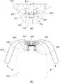
도 1 은 본 발명의 전체적인 모습을 나타낸 사시도.
도 2 는 본 발명의 등받이 및 등받이지지대 그리고 지압부의 주요구성을 나타낸 분해사시도.
도 3 은 본 발명의 스토퍼의 일실시예를 나타낸 사시도.
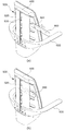
도 4 는 본 발명의 지압부의 작동상태와 스토퍼의 작동상태 일실시예를 나타낸 단면도 및 평면도.
도 5 는 본 발명의 지압부의 작동상태와 스토퍼의 작동상태 일실시예를 나타낸 단면도 및 평면도.
도 6 은 본 발명의 스토퍼 구성 중 스토퍼하우징의 주요구성을 나타낸 부분 사시도.
도 7 은 본 발명의 스토퍼의 주요구성을 나타낸 부분 사시도.1 is a perspective view showing the overall appearance of the present invention.
Figure 2 is an exploded perspective view showing the main configuration of the backrest and backrest support and acupressure part of the present invention.
Figure 3 is a perspective view showing an embodiment of the stopper of the present invention.
Figure 4 is a cross-sectional view and a plan view showing an embodiment of the operating state of the acupressure unit and the stopper of the present invention.
Figure 5 is a cross-sectional view and a plan view showing an embodiment of the operating state of the acupressure portion and the stopper of the present invention.
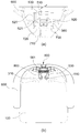
Figure 6 is a partial perspective view showing the main configuration of the stopper housing of the stopper configuration of the present invention.
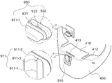
Figure 7 is a partial perspective view showing the main configuration of the stopper of the present invention.
이하, 도면을 참조하여 본 발명의 지압볼을 구비한 기능성의자의 일실시예에 대하여 상세히 설명한다.Hereinafter, an embodiment of a functional chair having a shiatsu ball of the present invention will be described in detail with reference to the drawings.
도 1 은 본 발명의 전체적인 모습을 나타낸 사시도, 도 2 는 본 발명의 등받이 및 등받이지지대 그리고 지압부의 주요구성을 나타낸 분해사시도, 도 3 은 본 발명의 스토퍼의 일실시예를 나타낸 사시도, 도 4 는 본 발명의 지압부의 작동상태와 스토퍼의 작동상태 일실시예를 나타낸 단면도 및 평면도, 도 5 는 본 발명의 지압부의 작동상태와 스토퍼의 작동상태 일실시예를 나타낸 단면도 및 평면도, 도 6 은 본 발명의 스토퍼 구성 중 스토퍼하우징의 주요구성을 나타낸 부분 사시도, 도 7 은 본 발명의 스토퍼의 주요구성을 나타낸 부분 사시도에 관한 것이다.Figure 1 is a perspective view showing the overall shape of the present invention, Figure 2 is an exploded perspective view showing the main configuration of the backrest and the backrest of the present invention and the pressure part, Figure 3 is a perspective view showing an embodiment of the stopper of the present invention, Figure 4 is Fig. 5 is a cross-sectional view and a plan view showing one embodiment of an operating state of a pressure part of the present invention and an operating state of a stopper. Partial perspective view showing the main configuration of the stopper housing of the stopper configuration of, Figure 7 relates to a partial perspective view showing the main configuration of the stopper of the present invention.
도 1 을 참조하면 본 발명의 지압볼을 구비한 기능성의자는 일반의자와 동일한 구조인 좌판(100), 한쌍의 팔걸이(600) 및 등받이(300), 상기 좌판(100)을 바닥면으로부터 이격시키며, 좌판(100)을 간편하게 이동시키기 위한 회전바퀴(210)가 장착된 좌판지지부(200)를 구비한다.Referring to Figure 1, the functional chair equipped with the shiatsu ball of the present invention has the same structure as the general chair, the
이때, 좌판(100)은 소정의 두께를 가지며, 완충 효과를 갖는 재질(스펀지, 발포우레탄 등)로 제작될 수 있다. 그리고, 좌판지지부(200)는 좌판(100)의 하단에 구비되어 좌판(100)을 지지한다.At this time, the
도 1 및 도 2 를 참조하면 등받이(300)는 좌판(100)의 일측에 결합되며 상하방향으로 세워지되, 일정각도로 경사를 유지하며 세워져 사용자가 좌판(100)에 앉는 경우 안락함과 편안함을 제공할 수 있다. 이때, 등받이(300)에는 지압홀(310)이 관통형성되며, 상기의 지압홀(310)은 다수개로 형성되어 상하방향으로 일정간격 이격배치된다. Referring to Figures 1 and 2, the
한편, 등받이(300)의 후방에는 등받이(300)를 지지하는 등받이지지대(400)가 장착된다. 등받이지지대(400)는 등받이(300)가 사용자의 무게에 의해 변형되는 것을 방지해줄 수 있도록 등받이(300)의 가장자리를 지지해준다. Meanwhile, a backrest support 400 for supporting the
즉, 등받이지지대(400)의 중앙에는 등받이지지대(400)를 관통하는 개구면(S)이 형성되며, 개구면(S)의 가장자리를 따라 등받이지지대(400)의 뒤틀림을 잡아주는 내부격벽(410)이 형성된다.That is, the center of the
이때, 도 1 내지 도 4 를 참조하면 등받이지지대(400)에 회전가능하도록 장착되어 좌판(100)에 앉아있는 사용자의 등 부위를 지압시켜주는 한쌍의 지압부(500)가 구비된다. 지압부(500)에는 지압볼(510)이 일정간격 이격되면서 다수개 형성되는데, 이때, 지압부(500)가 회전하면서 지압볼(510)이 지압홀(310)로 인출 또는 인입되면서 사용자의 등 부위를 가압 또는 가압해제할 수 있다. In this case, referring to FIGS. 1 to 4, a pair of
지압부(500)의 회전은 상기의 한쌍의 팔걸이(600)를 통해 제어할 수 있다. 즉, 팔걸이(600)는 지압부(500)의 일측에 각각 고정되며, 지압볼(510)이 지압홀(310)로 인출되도록 사용자가 팔걸이(600)를 좌우방향으로 밀면서 지압부(500)를 회전시키면 지압볼(510)이 지압홀(310)로 인출될 수 있는 것이다. The rotation of the
그리고, 도 2 를 참조하면, 좌판(100)과 등받이지지대(400) 사이에는 좌판(100)과 등받이(300) 및 등받이지지대(400)를 상호간 고정시키는 좌판연결대(700)가 더 구비된다. 좌판연결대(700)를 통해 좌판(100) 및 등받이(300), 등받이지지대(400)의 내구성을 향상시킬 수 있다.And, referring to Figure 2, between the
도 3 을 참조하면 등받이지지대(400) 지압부(500)에 장착되어 지압부(500)의 회전을 제어하는 스토퍼(900)가 더 구비된다. 스토퍼(900)는 등받이지지대(400)와 지압부(500) 사이에 삽입되면서 지압부(500)의 회전을 저지한다. 즉 사용자가 스토퍼(900)를 파지한 후 등받이지지대(400)와 지압부(500) 사이의 이격된 공간으로 스토퍼(900)를 삽입할 수 있다. 한편, 사용자가 팔걸이(600)를 이용하여 지압을 하고자 하는 경우 지압부(500)가 회전되도록 스토퍼(900)를 등받이지지대(400)와 지압부(500)의 사이에서 인출하여 지압을 수행할 수 있다. Referring to FIG. 3, a
도 2 를 참조하면 지압부(500)는 지압판(520), 롤러브라켓(530), 제1 회전축(540) 및 제2 회전축(550)을 포함한다. 먼저 지압판(520)은 소정의 두께를 이루며 상하방향으로 세워지질 수 있으며, 바람직하게는 등받이지지대(400)의 개구면(S) 내에 위치한다. Referring to FIG. 2, the
롤러브라켓(530)은 지압판(520)의 일측면, 즉, 등받이(300)와 마주보는 지압판(520)의 일측면에 형성되며, 롤러브라켓(530)의 끝단에는 지압볼(510)이 회전가능하도록 장착된다. 롤러브라켓(530)은 지압판(520)과 일체 회전할 수 있다. The
제1 및 제2 회전축(540,550)은 지압판(520)의 상측과 하측에 각각 위치하여 상하방향으로 연장되면서 지압판(520)과 일체를 이룬다. 이로써, 지압판(520)은 제1 및 제2 회전축(540,550)을 중심으로 회전할 수 있다. The first and
도 2 및 도 4 와 도 5 를 참조하면 제2 회전축(550)에는 제2 회전축(550)의 연장되는 방향과 교차되는 방향(수평방향)으로 연장형성되는 지지로드(560)가 구비된다. 지지로드(560)는 한쌍을 이루도록 각각의 제2 회전축(550)에 형성된다. 지지로드(560)의 끝단에는 지지로드(560)를 관통하는 체결홀(561)이 형성된다. 2 and 4 and 5, the second
이때, 한쌍의 지지로드(560) 사이에는 탄성부재(800)가 구비되며, 탄성부재(800)의 일측과 타측이 각각의 지지로드(560)의 체결홀(561)에 고정되면서 한쌍의 지압판(520)을 탄성지지한다. 즉, 사용자가 팔걸이(600)를 가압하여 지압판(520)이 회전시킨 후 인출된 지압볼(510)을 지압홀(310)로 인입시키기 위해 팔걸이(600)를 가압하는 가압력을 해제하면 탄성부재(800)의 탄성력으로 지압판(520)과 팔걸이(600)는 원래 위치로 이동할 수 있다. At this time, between the pair of
한편, 탄성부재(800)는 제2 회전축(550)과 제2 지지홀더(720) 또는 제1 회전축(540) 및 제1 지지홀더(420) 사이에 구비되는 코일스프링 형태로 제작될 수 있다. 탄성부재(800)가 코일스프링 형태로 제작되면서 조립 및 유지보수가 간편해질 수 있고, 복수개의 팔걸이(600)를 각각 독립적으로 제어할 수 있는 이점을 제공할 수 있다. Meanwhile, the
도 3 을 참조하면 스토퍼(900)는 등받이지지대(400)와 지압부(500) 사이에 삽입될 수 있도록 소정의 두께를 가지며 형성되고, 일측면에 복수개의 고정홈(901)이 일정간격 이격되면서 함입 형성된다. Referring to FIG. 3, the
즉, 스토퍼(900)가 등받이지지대(400)와 지압부(500) 사이에 삽입되도록 장착되는 경우 고정홈(901)이 롤러브라켓(530)에 삽입되면서 스토퍼(900)가 고정된다. 이때, 고정홈(901)의 형상은 롤러브라켓(530)의 형상에 맞게 가공되는 것이 바람직하다. That is, when the
이처럼 스토퍼(900)가 장착되면서 지압판(520)이 스토퍼(900)의 측면과 접촉되어 지압부(500)의 회전이 제한될 수 있는 것이다. As such, as the
도 2 를 참조하면 등받이지지대(400)의 내측면, 즉, 등받이(300)와 마주보는 등받이지지대(400)의 일면에는 제1 회전축(540)이 지지되는 제1 지지홀더(420)가 형성된다. 바람직하게 제1 지지홀더(420)는 등받이지지대(400)의 상측에 형성될 수 있으며, 지압판(520)이 개구면(S) 내에서 원활하게 회전할 수 있도록 제1 회전축(540)의 끝단 측면을 지지하는 구조로 형성될 수 있다. Referring to FIG. 2, a
그리고, 등받이지지대(400)의 하측에는 좌판연결대(700)가 고정되는 좌판연결대 결합돌기(430)가 돌출 형성되며, 별도의 고정피스로 상호 고정된다. In addition, a seating plate connecting
이때, 내부격벽(410)에는 제1 회전축(540)이 관통되는 상부 끼움홈(411)과 제2 회전축(550)이 관통되는 하부 끼움홈(412)이 더 형성된다. 상부 끼움홈(411)과 하부 끼움홈(412)은 상호 마주보도록 위치한다. 상부 끼움홈(411) 및 하부 끼움홈(412)의 가장자리가 제1 및 제2 회전축(540,550)의 측면과 밀착되도록 접촉되면서 제1 및 제2 회전축(540,550)을 지지해준다. 이로써, 지압판(520)의 회전 시 제1 및 제2 회전축(540,550)의 유격 발생을 최소화하여 지압판(520)의 원활한 회전을 도모할 수 있다. At this time, the
도 2 를 참조하면 좌판연결대(700)는 좌판연결로드(710) 및 지압부 고정플레이트(720)를 포함한다. 좌판연결로드(710)의 일측은 좌판(100)의 일측과 결합되며, 소정의 두께를 갖는 판 형상을 이루면서 타측이 절곡된 형상을 갖는다. 이때, 절곡된 좌판연결로두(710)의 타측단에 지압부 고정플레이트(720)가 형성된다. 지압부 고정플레이트(720)는 소정의 두께를 갖는 판형상을 이루며, 좌판연결대 결합돌기(430)와 결합된다. 2, the seat
이때, 지압부 고정플레이트(720)의 상단에는 한쌍의 제2 회전축(550)이 삽입될 수 있는 제2 지지홀더(730)가 구비될 수 있으며, 제2 회전축(550)이 제2 지지홀더(730)에 회전될 수 있는 구조로 삽입된다. 따라서 지압판(520)이 제1 및 제2 회전축(540,550)을 중심으로 회전할 수 있는 것이다. At this time, a
도 2 내지 도 7 을 참조하면 등받이지지대(400)에 장착되어 지압부(500)의 회전을 제어하는 스토퍼(900)가 더 구비된다. 즉, 스토퍼(900)의 조작으로 사용자가 지압의 수행 여부를 선택할 수 있다. 2 to 7, a
스토퍼(900)는 스토퍼하우징(910), 스토퍼몸체(920) 및 스토퍼핸들(930)을 포함한다. 먼저 스토퍼하우징(910)은 등받이지지대(400)의 내측면 중 바람직하게는 하측에 형성되며, 중앙에 상하방향으로 연장되는 레일홈(911)이 형성된다. The
스토퍼몸체(920)는 내부격벽(410)에 스토퍼인입홈(413)이 관통형성되는 경우 스토퍼인입홈(413)에 끼워져 상하방향으로 슬라이딩된다. 스토퍼몸체(920)의 상하이동에 따라 스토퍼몸체(920)에 지압판(520)이 접촉되면서 지압판(520)의 회전을 제어한다. 즉, 스토퍼몸체(920)가 상승하여 지압판(520)과 접촉되면 지압판(520)의 회전이 저지되고, 스토퍼몸체(920)가 하강하여 지압판(520)과의 접촉이 해제되면 지압판(520)은 자유롭게 회전될 수 있는 것이다. The
한편, 지압판(520)의 일측에는 스토퍼몸체(920)과 접촉되는 스톱돌기(521)가 돌출 형성될 수 있다. 스톱돌기(521)에 스토퍼몸체(920)가 지지되면서 지압판(520)의 회전을 제어할 수 있다.Meanwhile, a
스토퍼핸들(930)은 스토퍼몸체(920)의 일측에 구비되어 사용자가 스토퍼핸들(930)을 파지하여 스토퍼몸체(920)의 상하이동을 조작한다. 이때, 스토퍼핸들(930)은 레일홈(911)에 장착되어 레일홈(911)의 연장방향을 따라 안내되어 이동할 수 있다. 스토퍼핸들(930)은 등받이지지대(400)의 외부에 노출되어 사용자가 쉽게 파지할 수 있다.The
도 7 을 참조하면 스토퍼핸들(930)은 제1 지지판(931), 제2 지지판(932) 및 가이드봉(933)을 포함한다. 제1 지지판(931)은 스토퍼하우징(910)의 외측면에 밀착되며 일측에 등받이지지대(400)의 외부에 노출되어 사용자가 파지하는 핸들(931-1)이 더 형성된다. Referring to FIG. 7, the
제2 지지판(932)은 스토퍼몸체(920)의 측면으로부터 돌출 형성되어 스토퍼하우징(910)의 내측면과 밀착된다. 이때, 제1 지지판(932)은 제2 지지판(931)과 일정간격 이격되는데, 이격되는 간격은 스토퍼하우징(910)의 두께와 동일한 간격을 이룬다. The
가이드봉(933)은 레일홈(911)을 관통하는 소정의 직경을 갖는 봉형상이며, 제1 지지판(931)과 제2 지지판(932) 사이에 구비된다. 이때, 레일홈(911)의 일측과 타측이 제1 지지판(931)과 제2 지지판(932)에 각각 연결됨에 따라 제1 지지판(931)과 제2 지지판(932)은 스토퍼하우징(910)의 외측면과 내측면에 밀착될 수 있다.The
도 6 및 도 7 을 참조하면 레일홈(911)은 슬라이딩홈(911-1)과 고정레일홈(911-2)으로 구획될 수 있다. 슬라이딩홈(911-1)은 가이드봉(933)과 함께 스토퍼몸체(920)를 상하이동시키도록 상하방향으로 연장 형성된다. 고정레일홈(911-2)은 바람직하게는 슬라이딩홈(911-1)의 상측에 위치하며, 스토퍼몸체(920)가 지압판(520)을 지지한 상태를 유지시키기 위해 가이드봉(933)이 밀착되면서 안착된다. 6 and 7, the
이때, 슬라이딩홈(911-1)과 고정레일홈(911-2) 사이에는 멈춤돌기(911-3)가 돌출 형성된다. 멈춤돌기(911-2)는 가이드봉(933)을 고정레일홈(911-2)에 안착된 상태를 유지시키기 위해, 즉, 고정레일홈(911-2)은 되어 고정레일홈(911-2)에 안착된 가이드봉(933)이 자체 중량으로 인해 하방향으로 이동하는 현상을 방지하도록 가이드봉(933)을 지지한다. 따라서, 사용자가 핸들(931-1)을 파지하여 일정토크 이상의 힘을 가해 조작하면 가이드봉(933)과 함께 스토퍼몸체(920)가 상하방향으로 이동할 수 있다. At this time, a stop protrusion 911-3 is formed between the sliding groove 911-1 and the fixed rail groove 911-2. The stop protrusion 911-2 is a fixed rail groove 911-2 to maintain the
이와 같은 구성으로 인한 본 발명의 지압볼을 구비한 기능성의자는 일상에서는 학습용의자나 사무용의자 등으로 사용하다가 등근육이나 척추주변 근육 등을 가압하여 혈액순환을 유도하고자 할 때 팔걸이를 조작하여 착석한 사용자의 자세교정이나 피로를 풀어줄 수 있는 장점이 있다. The functional chair equipped with the acupressure ball of the present invention due to such a configuration is used as a learning chair or an office chair in everyday life, and is seated by manipulating the armrests when inducing blood circulation by pressing back muscles or muscles around the spine. There is an advantage that can relieve the posture or fatigue of the user.
100 : 좌판
200 : 좌판지지부
300 : 등받이
400 : 등받이지지대
500 : 지압부
510 : 지압볼
520 : 지압판
530 : 롤러브라켓
540 : 제1 회전축
550 : 제2 회전축
560 : 지지로드
600 : 팔걸이
700 : 좌판연결대
800 : 탄성부재
900 : 스토퍼
910 : 스토퍼하우징
920 : 스토퍼몸체
930 : 스토퍼핸들100: seat 200: seat support
300: backrest 400: backrest support
500: Shiatsu part 510: Shiatsu ball
520: acupressure plate 530: roller bracket
540: first rotation axis 550: second rotation axis
560: support rod 600: armrest
700: seat plate connecting rod 800: elastic member
900: stopper 910: stopper housing
920: stopper body 930: stopper handle
Claims (5)
상기 좌판(100)을 지지하도록 상기 좌판(100)의 하단에 구비되며, 일측에 상기 좌판(100)을 이동시키기 위한 회전바퀴(210)가 장착되는 좌판지지부(200);
상기 좌판(100)의 일측에 결합되어 상하방향으로 세워지며, 일정간격 이격배치되는 지압홀(310)이 관통형성되는 등받이(300);
상기 등받이(300)의 후방에 장착되며, 중앙에 개구면(S)이 관통형성되되, 상기 개구면(S)의 가장자리를 따라 내부격벽(410)이 연장형성되는 등받이지지대(400);
상기 등받이지지대(400)에 회전가능하도록 장착되며, 회전함에 따라 상기 지압홀(310)로 인출 또는 인입되는 지압볼(510)이 다수개 형성되는 한쌍의 지압부(500);
상기 지압부(500)의 일측에 각각 고정되며, 상기 지압볼(510)이 상기 지압홀(310)로 인출되도록 상기 지압부(500)를 회전시키는 한쌍의 팔걸이(600);
일측이 상기 좌판(100)에 고정되고, 타측이 상기 등받이지지대(400)에 고정되어 상기 등받이와 상기 좌판(100)을 고정하는 좌판연결대(700);
상기 등받이지지대(400) 또는 상기 지압부(500)에 장착되어 상기 지압부(500)의 회전을 제어하는 스토퍼(900);
를 포함하는 것을 특징으로 하는 지압볼을 구비한 기능성의자.A seat plate 100 having a predetermined thickness;
A seat plate support part 200 provided at a lower end of the seat plate 100 to support the seat plate 100 and having a rotating wheel 210 for moving the seat plate 100 on one side;
A backrest 300 coupled to one side of the seat plate 100 and erected in a vertical direction, and through which acupressure holes 310 spaced at regular intervals are formed;
A backrest support 400 mounted to the rear of the backrest 300, the opening surface S being penetrated through the center, and the inner partition 410 extending along the edge of the opening surface S;
A pair of acupressure parts 500 mounted rotatably on the backrest support 400 and a plurality of acupressure balls 510 drawn or drawn into the acupressure holes 310 as they rotate;
A pair of armrests 600 fixed to one side of the acupressure part 500 and rotating the acupressure part 500 so that the acupressure ball 510 is drawn out into the acupressure hole 310;
One side is fixed to the seat plate 100, the other side is fixed to the back support 400, the seat back and the seat plate connecting unit 700 for fixing the seat plate 100;
A stopper 900 mounted on the backrest support 400 or the acupressure part 500 to control rotation of the acupressure part 500;
Functional chair with a shiatsu ball, characterized in that it comprises a.
상기 지압부(500)는 상하방향으로 세워지는 지압판(520);
상기 지압판(520)의 일측에 돌출 형성되며, 상기 지압볼(510)이 회전가능하도록 장착되는 롤러브라켓(530);
상기 지압판(520)의 상측과 하측에 상하방향으로 각각 연장 형성되는 제1 회전축(540) 및 제2 회전축(550);을 포함하고,
상기 제2 회전축(550)에는 수평방향으로 연장형성되며 끝단에 체결홀(561)이 각각 형성되는 한쌍의 지지로드(560)가 형성되며,
상기 한쌍의 지지로드(560) 사이에는 상기 팔걸이(600)를 가압하는 가압력이 해제되면 상기 인출된 지압볼(510)을 지압홀(310)로 인입시키도록 상기 한쌍의 지압부(500)를 탄성지지하는 탄성부재(800);가 더 구비되는 것을 특징으로 하는 지압볼을 구비한 기능성의자.According to claim 2,
The acupressure unit 500 is a vertical pressure plate (520) erected in the vertical direction;
A roller bracket 530 formed to protrude on one side of the acupressure plate 520 and mounted such that the acupressure ball 510 is rotatable;
It includes; the first rotation shaft 540 and the second rotation shaft 550 are formed to extend in the vertical direction on the upper and lower sides of the acupressure plate 520;
A pair of support rods 560 are formed on the second rotation shaft 550 extending in the horizontal direction and fastening holes 561 are formed at the ends, respectively.
When the pressing force for pressing the armrest 600 is released between the pair of support rods 560, the pair of acupressure parts 500 are elastic to draw the drawn acupressure balls 510 into the acupressure holes 310. Functional member having a shiatsu ball, characterized in that further provided ;;
상기 스토퍼(900)는 소정의 두께를 가지며 측면에 고정홈(901)이 함입 형성되되,
상기 스토퍼(900)가 장착되는 경우 상기 롤러브라켓(530)에 고정홈(901)이 삽입되어 상기 스토퍼(900)가 고정되고, 상기 지압판(520)이 상기 스토퍼(900)의 측면과 접촉되면서 상기 지압부(500)의 회전이 제한되는 것을 특징으로 하는 지압볼을 구비한 기능성의자. According to claim 2,
The stopper 900 has a predetermined thickness and is formed with a fixing groove 901 embedded in the side,
When the stopper 900 is mounted, the fixing groove 901 is inserted into the roller bracket 530 so that the stopper 900 is fixed, and the acupressure plate 520 is in contact with the side of the stopper 900. Functional chair with a shiatsu ball, characterized in that the rotation of the acupressure unit 500 is limited.
상기 스토퍼(900)는 상기 등받이지지대(400)의 내측면에 형성되며 상하방향을 따라 연장형성되는 레일홈(911)을 포함하는 스토퍼하우징(910);
상기 내부격벽(410)을 관통하며 형성되는 스토퍼인입홈(413)에 끼워져 상하방향으로 슬라이딩되되, 상하 이동에 따라 상기 지압판(520)의 회전을 제어하도록 상기 지압판(520)과 접촉 또는 접촉해제되는 스토퍼몸체(920);
상기 스토퍼몸체(920)의 상하이동을 제어하도록 상기 레일홈(911)에 장착되며 상기 등받이지지대(400)의 외부에 노출되는 스토퍼핸들(930);
을 포함하는 것을 특징으로 하는 지압볼을 구비한 기능성의자. According to claim 2,
The stopper 900 is a stopper housing 910 including a rail groove 911 formed on an inner surface of the backrest support 400 and extending along a vertical direction;
It is inserted into the stopper inlet groove 413 formed through the inner partition wall 410 and is slid in the vertical direction. Stopper body 920;
A stopper handle 930 mounted on the rail groove 911 and exposed to the outside of the backrest support 400 to control the movement of the stopper body 920;
Functional chair with a shiatsu ball, characterized in that it comprises a.
상기 스토퍼핸들(930)은 상기 스토퍼하우징(910)의 외측면에 밀착되며, 상기 등받이지지대(400)의 외부에 노출된 핸들(931-1)을 포함하는 제1 지지판(931);
상기 스토퍼하우징(910)의 내측면에 밀착되는 제2 지지판(932);
상기 레일홈(911)을 관통하며 일측과 타측이 상기 제1 지지판(931)과 제2 지지판(932)에 각각 연결되는 가이드봉(933);을 포함하고,
상기 레일홈(911)은 상기 가이드봉(933)이 슬라이딩되도록 연장되는 슬라이딩홈(911-1);
상기 슬라이딩홈(911-1)의 일측에 형성되어 상기 가이드봉(933)이 안착되는 고정레일홈(911-2);을 포함하되,
상기 슬라이딩홈(911-1)과 상기 고정레일홈(911-2) 사이에는 상기 가이드봉(933)이 고정레일홈(911-2)에 안착된 상태를 유지시키기 위해 상기 가이드봉(933)을 지지하는 멈춤돌기(911-3);가 돌출 형성되는 것을 특징으로 하는 지압볼을 구비한 기능성의자.The method of claim 6,
The stopper handle 930 is in close contact with the outer surface of the stopper housing 910, a first support plate 931 including a handle 91-1 exposed on the outside of the backrest support 400;
A second support plate 932 in close contact with an inner surface of the stopper housing 910;
It includes; guide rods 933 penetrating the rail groove 911 and one side and the other side connected to the first support plate 931 and the second support plate 932, respectively;
The rail groove 911 is a sliding groove (911-1) extending so that the guide rod (933) is sliding;
It is formed on one side of the sliding groove (911-1) is fixed rail groove (911-2) on which the guide rod (933) is seated;
Between the sliding groove 911-1 and the fixed rail groove 911-2, the guide rod 933 is maintained to maintain the state in which the guide rod 933 is seated in the fixed rail groove 911-2. Support stopper (911-3); Functional chair with a shiatsu ball characterized in that the protrusion is formed.
Priority Applications (5)
| Application Number | Priority Date | Filing Date | Title |
|---|---|---|---|
| KR1020180125115A KR20200044401A (en) | 2018-10-19 | 2018-10-19 | a office chair with massage function |
| JP2018220089A JP2020065899A (en) | 2018-10-19 | 2018-11-26 | Functional chair with acupressure balls |
| CN201811425972.XA CN111067291A (en) | 2018-10-19 | 2018-11-27 | Functional chair with formed finger pressing ball |
| EP18208553.0A EP3639699A1 (en) | 2018-10-19 | 2018-11-27 | Functional chair with massage ball |
| US16/202,023 US20200121547A1 (en) | 2018-10-19 | 2018-11-27 | Functional chair with massage ball |
Applications Claiming Priority (1)
| Application Number | Priority Date | Filing Date | Title |
|---|---|---|---|
| KR1020180125115A KR20200044401A (en) | 2018-10-19 | 2018-10-19 | a office chair with massage function |
Publications (1)
| Publication Number | Publication Date |
|---|---|
| KR20200044401A true KR20200044401A (en) | 2020-04-29 |
Family
ID=64664024
Family Applications (1)
| Application Number | Title | Priority Date | Filing Date |
|---|---|---|---|
| KR1020180125115A KR20200044401A (en) | 2018-10-19 | 2018-10-19 | a office chair with massage function |
Country Status (5)
| Country | Link |
|---|---|
| US (1) | US20200121547A1 (en) |
| EP (1) | EP3639699A1 (en) |
| JP (1) | JP2020065899A (en) |
| KR (1) | KR20200044401A (en) |
| CN (1) | CN111067291A (en) |
Families Citing this family (5)
| Publication number | Priority date | Publication date | Assignee | Title |
|---|---|---|---|---|
| US11771230B2 (en) * | 2020-02-04 | 2023-10-03 | David Navarro | Ergonomic massage chair |
| CN112545232B (en) * | 2020-11-13 | 2023-11-03 | 安徽精正家具制造有限公司 | Office chair with lumbar support structure and surface treatment method thereof |
| CN112618311B (en) * | 2020-12-09 | 2023-03-21 | 中南林业科技大学 | Health-care massage chair |
| CN113951651A (en) * | 2021-11-02 | 2022-01-21 | 安吉米立家具有限公司 | Massage office chair |
| CN113844349A (en) * | 2021-11-04 | 2021-12-28 | 苏州工业园区报关有限公司 | Vehicle monitoring equipment based on artificial intelligence |
Citations (3)
| Publication number | Priority date | Publication date | Assignee | Title |
|---|---|---|---|---|
| KR101384199B1 (en) | 2013-03-07 | 2014-05-27 | 주식회사 제라진코리아 | Functional chair equipped with massage balls |
| KR101565257B1 (en) | 2014-09-11 | 2015-11-02 | 주식회사 제라진코리아 | A back pad of a chair having massage function |
| KR101586607B1 (en) | 2015-03-31 | 2016-01-19 | 정낙궁 | Functional chair |
Family Cites Families (3)
| Publication number | Priority date | Publication date | Assignee | Title |
|---|---|---|---|---|
| KR101003756B1 (en) * | 2010-03-11 | 2010-12-28 | 양문석 | Chair having two piece back panel with massager |
| KR101152330B1 (en) * | 2012-03-16 | 2012-06-08 | 양문석 | Functional chair |
| CN204363484U (en) * | 2015-01-08 | 2015-06-03 | 艾迈斯按摩椅(上海)有限公司 | A kind of waist support neck-guarding massage chair |
-
2018
- 2018-10-19 KR KR1020180125115A patent/KR20200044401A/en active IP Right Grant
- 2018-11-26 JP JP2018220089A patent/JP2020065899A/en active Pending
- 2018-11-27 CN CN201811425972.XA patent/CN111067291A/en active Pending
- 2018-11-27 US US16/202,023 patent/US20200121547A1/en not_active Abandoned
- 2018-11-27 EP EP18208553.0A patent/EP3639699A1/en not_active Withdrawn
Patent Citations (3)
| Publication number | Priority date | Publication date | Assignee | Title |
|---|---|---|---|---|
| KR101384199B1 (en) | 2013-03-07 | 2014-05-27 | 주식회사 제라진코리아 | Functional chair equipped with massage balls |
| KR101565257B1 (en) | 2014-09-11 | 2015-11-02 | 주식회사 제라진코리아 | A back pad of a chair having massage function |
| KR101586607B1 (en) | 2015-03-31 | 2016-01-19 | 정낙궁 | Functional chair |
Also Published As
| Publication number | Publication date |
|---|---|
| JP2020065899A (en) | 2020-04-30 |
| CN111067291A (en) | 2020-04-28 |
| EP3639699A1 (en) | 2020-04-22 |
| US20200121547A1 (en) | 2020-04-23 |
Similar Documents
| Publication | Publication Date | Title |
|---|---|---|
| KR20200044401A (en) | a office chair with massage function | |
| US20190209886A1 (en) | Systems and Methods for Providing Ergonomic Chairs | |
| US9364715B2 (en) | Spine rehabilitation exercise device | |
| US7789463B2 (en) | Chair which is used in waist enhancement | |
| US20110034839A1 (en) | Massage recliner | |
| JP2017533069A (en) | Office, work, and leisure chairs and chair or seat surface retrofit kits for creating subthreshold movements for seated persons | |
| KR100625850B1 (en) | The wholr body massager | |
| KR100916753B1 (en) | Memory apparatus for the back of a chair | |
| KR101374570B1 (en) | A office chair with massage function | |
| KR102138836B1 (en) | Chair with tilting structure of seat | |
| KR20160112475A (en) | Chair for pelvis training and lumbar posture correction | |
| KR20210015184A (en) | Office chair with neck massager | |
| JPH0441856Y2 (en) | ||
| KR101241415B1 (en) | Massager | |
| KR100942429B1 (en) | Seat board of roller type and functional chair using the same | |
| CN101683300B (en) | Massaging machine | |
| CN103876503A (en) | Rocking chair | |
| CN210227464U (en) | Novel multi-functional administrative office chair | |
| KR200407079Y1 (en) | Massage chairs with mattress | |
| KR101187635B1 (en) | A seat for stabilization of pelvic girdle | |
| KR102533006B1 (en) | Tilting and sliding type cervical muscle relaxation device | |
| KR101374566B1 (en) | A office chair with massage function | |
| KR200494583Y1 (en) | Backed Chair | |
| KR102485939B1 (en) | Office massage chair with dual massage module | |
| KR102290271B1 (en) | Multi-function Chair |
Legal Events
| Date | Code | Title | Description |
|---|---|---|---|
| E902 | Notification of reason for refusal | ||
| E701 | Decision to grant or registration of patent right |