KR20200042428A - Novel compound and organic light emitting device comprising the same - Google Patents
Novel compound and organic light emitting device comprising the same Download PDFInfo
- Publication number
- KR20200042428A KR20200042428A KR1020190127309A KR20190127309A KR20200042428A KR 20200042428 A KR20200042428 A KR 20200042428A KR 1020190127309 A KR1020190127309 A KR 1020190127309A KR 20190127309 A KR20190127309 A KR 20190127309A KR 20200042428 A KR20200042428 A KR 20200042428A
- Authority
- KR
- South Korea
- Prior art keywords
- compound
- group
- layer
- formula
- mmol
- Prior art date
Links
- 0 CC(CC=C1)(C(*)=C1c(cc1)ccc1-c(cc1)ccc1-c1ccccc1)c1cccc2c1cccc2 Chemical compound CC(CC=C1)(C(*)=C1c(cc1)ccc1-c(cc1)ccc1-c1ccccc1)c1cccc2c1cccc2 0.000 description 3
- JBFLNIKMGXWYPU-UHFFFAOYSA-N Nc(c(-c1ccccc1)ccc1)c1Cl Chemical compound Nc(c(-c1ccccc1)ccc1)c1Cl JBFLNIKMGXWYPU-UHFFFAOYSA-N 0.000 description 2
- BIMSFWCFKDVSNO-UHFFFAOYSA-N Nc(c(Cl)ccc1)c1Br Chemical compound Nc(c(Cl)ccc1)c1Br BIMSFWCFKDVSNO-UHFFFAOYSA-N 0.000 description 1
- HUMMCEUVDBVXTQ-UHFFFAOYSA-N OB(c1cccc2ccccc12)O Chemical compound OB(c1cccc2ccccc12)O HUMMCEUVDBVXTQ-UHFFFAOYSA-N 0.000 description 1
- HXITXNWTGFUOAU-UHFFFAOYSA-N OB(c1ccccc1)O Chemical compound OB(c1ccccc1)O HXITXNWTGFUOAU-UHFFFAOYSA-N 0.000 description 1
- DTHFTWSZABOTMI-UHFFFAOYSA-N c(cc1)cc2c1[o]c(cc1)c2cc1N(c(cc1)cc2c1c1ccccc1c1ccccc21)c(c(-c1cccc2ccccc12)ccc1)c1-c1c(cccc2)c2ccc1 Chemical compound c(cc1)cc2c1[o]c(cc1)c2cc1N(c(cc1)cc2c1c1ccccc1c1ccccc21)c(c(-c1cccc2ccccc12)ccc1)c1-c1c(cccc2)c2ccc1 DTHFTWSZABOTMI-UHFFFAOYSA-N 0.000 description 1
- HNFZGNXBFFGHSI-UHFFFAOYSA-N c(cc1)ccc1-c(cc1)ccc1-c(cccc1-c2cccc3ccccc23)c1N(c(cc1)cc2c1[o]c1c2cccc1)c(cc1)cc2c1[o]c1ccccc21 Chemical compound c(cc1)ccc1-c(cc1)ccc1-c(cccc1-c2cccc3ccccc23)c1N(c(cc1)cc2c1[o]c1c2cccc1)c(cc1)cc2c1[o]c1ccccc21 HNFZGNXBFFGHSI-UHFFFAOYSA-N 0.000 description 1
- IRVPBDHNVYYGKO-UHFFFAOYSA-N c(cc1)ccc1-c1cccc(c2ccc3)c1[o]c2c3-c(cc1)ccc1N(c(cc1)ccc1-c1cccc2c1c1ccccc1[n]2-c1ccccc1)c(c(-c1ccccc1)ccc1)c1-c1ccccc1 Chemical compound c(cc1)ccc1-c1cccc(c2ccc3)c1[o]c2c3-c(cc1)ccc1N(c(cc1)ccc1-c1cccc2c1c1ccccc1[n]2-c1ccccc1)c(c(-c1ccccc1)ccc1)c1-c1ccccc1 IRVPBDHNVYYGKO-UHFFFAOYSA-N 0.000 description 1
- FYDULAQYLBDUMX-UHFFFAOYSA-N c(cc1)ccc1N(c(cc1)cc2c1c1ccccc1[o]2)c(c(-c1cccc2ccccc12)ccc1)c1-c1c(cccc2)c2ccc1 Chemical compound c(cc1)ccc1N(c(cc1)cc2c1c1ccccc1[o]2)c(c(-c1cccc2ccccc12)ccc1)c1-c1c(cccc2)c2ccc1 FYDULAQYLBDUMX-UHFFFAOYSA-N 0.000 description 1
- DPHMMXNMHFYXDJ-UHFFFAOYSA-N c(cc1)ccc1N(c1c(c(cccc2)c2[o]2)c2ccc1)c(c(-c1cccc2c1cccc2)ccc1)c1-c1cccc2c1cccc2 Chemical compound c(cc1)ccc1N(c1c(c(cccc2)c2[o]2)c2ccc1)c(c(-c1cccc2c1cccc2)ccc1)c1-c1cccc2c1cccc2 DPHMMXNMHFYXDJ-UHFFFAOYSA-N 0.000 description 1
- MJDAIEDLRJAURM-UHFFFAOYSA-N c(cc1c2ccc3)ccc1[o]c2c3N(c(cc1)cc2c1c1ccccc1c1ccccc21)c(c(-c1cccc2c1cccc2)ccc1)c1-c1cccc2c1cccc2 Chemical compound c(cc1c2ccc3)ccc1[o]c2c3N(c(cc1)cc2c1c1ccccc1c1ccccc21)c(c(-c1cccc2c1cccc2)ccc1)c1-c1cccc2c1cccc2 MJDAIEDLRJAURM-UHFFFAOYSA-N 0.000 description 1
Images

Classifications
-
- C—CHEMISTRY; METALLURGY
- C07—ORGANIC CHEMISTRY
- C07C—ACYCLIC OR CARBOCYCLIC COMPOUNDS
- C07C211/00—Compounds containing amino groups bound to a carbon skeleton
- C07C211/43—Compounds containing amino groups bound to a carbon skeleton having amino groups bound to carbon atoms of six-membered aromatic rings of the carbon skeleton
- C07C211/54—Compounds containing amino groups bound to a carbon skeleton having amino groups bound to carbon atoms of six-membered aromatic rings of the carbon skeleton having amino groups bound to two or three six-membered aromatic rings
-
- C—CHEMISTRY; METALLURGY
- C07—ORGANIC CHEMISTRY
- C07D—HETEROCYCLIC COMPOUNDS
- C07D209/00—Heterocyclic compounds containing five-membered rings, condensed with other rings, with one nitrogen atom as the only ring hetero atom
- C07D209/56—Ring systems containing three or more rings
- C07D209/80—[b, c]- or [b, d]-condensed
- C07D209/82—Carbazoles; Hydrogenated carbazoles
-
- C—CHEMISTRY; METALLURGY
- C07—ORGANIC CHEMISTRY
- C07D—HETEROCYCLIC COMPOUNDS
- C07D307/00—Heterocyclic compounds containing five-membered rings having one oxygen atom as the only ring hetero atom
- C07D307/77—Heterocyclic compounds containing five-membered rings having one oxygen atom as the only ring hetero atom ortho- or peri-condensed with carbocyclic rings or ring systems
- C07D307/91—Dibenzofurans; Hydrogenated dibenzofurans
-
- C—CHEMISTRY; METALLURGY
- C07—ORGANIC CHEMISTRY
- C07D—HETEROCYCLIC COMPOUNDS
- C07D333/00—Heterocyclic compounds containing five-membered rings having one sulfur atom as the only ring hetero atom
- C07D333/50—Heterocyclic compounds containing five-membered rings having one sulfur atom as the only ring hetero atom condensed with carbocyclic rings or ring systems
- C07D333/76—Dibenzothiophenes
-
- C—CHEMISTRY; METALLURGY
- C09—DYES; PAINTS; POLISHES; NATURAL RESINS; ADHESIVES; COMPOSITIONS NOT OTHERWISE PROVIDED FOR; APPLICATIONS OF MATERIALS NOT OTHERWISE PROVIDED FOR
- C09K—MATERIALS FOR MISCELLANEOUS APPLICATIONS, NOT PROVIDED FOR ELSEWHERE
- C09K11/00—Luminescent, e.g. electroluminescent, chemiluminescent materials
- C09K11/06—Luminescent, e.g. electroluminescent, chemiluminescent materials containing organic luminescent materials
-
- H01L51/0059—
-
- H01L51/0073—
-
- H01L51/50—
-
- H—ELECTRICITY
- H10—SEMICONDUCTOR DEVICES; ELECTRIC SOLID-STATE DEVICES NOT OTHERWISE PROVIDED FOR
- H10K—ORGANIC ELECTRIC SOLID-STATE DEVICES
- H10K50/00—Organic light-emitting devices
-
- H—ELECTRICITY
- H10—SEMICONDUCTOR DEVICES; ELECTRIC SOLID-STATE DEVICES NOT OTHERWISE PROVIDED FOR
- H10K—ORGANIC ELECTRIC SOLID-STATE DEVICES
- H10K85/00—Organic materials used in the body or electrodes of devices covered by this subclass
- H10K85/60—Organic compounds having low molecular weight
- H10K85/631—Amine compounds having at least two aryl rest on at least one amine-nitrogen atom, e.g. triphenylamine
-
- H—ELECTRICITY
- H10—SEMICONDUCTOR DEVICES; ELECTRIC SOLID-STATE DEVICES NOT OTHERWISE PROVIDED FOR
- H10K—ORGANIC ELECTRIC SOLID-STATE DEVICES
- H10K85/00—Organic materials used in the body or electrodes of devices covered by this subclass
- H10K85/60—Organic compounds having low molecular weight
- H10K85/649—Aromatic compounds comprising a hetero atom
- H10K85/657—Polycyclic condensed heteroaromatic hydrocarbons
- H10K85/6574—Polycyclic condensed heteroaromatic hydrocarbons comprising only oxygen in the heteroaromatic polycondensed ring system, e.g. cumarine dyes
-
- C—CHEMISTRY; METALLURGY
- C09—DYES; PAINTS; POLISHES; NATURAL RESINS; ADHESIVES; COMPOSITIONS NOT OTHERWISE PROVIDED FOR; APPLICATIONS OF MATERIALS NOT OTHERWISE PROVIDED FOR
- C09K—MATERIALS FOR MISCELLANEOUS APPLICATIONS, NOT PROVIDED FOR ELSEWHERE
- C09K2211/00—Chemical nature of organic luminescent or tenebrescent compounds
- C09K2211/10—Non-macromolecular compounds
- C09K2211/1003—Carbocyclic compounds
- C09K2211/1007—Non-condensed systems
-
- C—CHEMISTRY; METALLURGY
- C09—DYES; PAINTS; POLISHES; NATURAL RESINS; ADHESIVES; COMPOSITIONS NOT OTHERWISE PROVIDED FOR; APPLICATIONS OF MATERIALS NOT OTHERWISE PROVIDED FOR
- C09K—MATERIALS FOR MISCELLANEOUS APPLICATIONS, NOT PROVIDED FOR ELSEWHERE
- C09K2211/00—Chemical nature of organic luminescent or tenebrescent compounds
- C09K2211/10—Non-macromolecular compounds
- C09K2211/1003—Carbocyclic compounds
- C09K2211/1014—Carbocyclic compounds bridged by heteroatoms, e.g. N, P, Si or B
-
- C—CHEMISTRY; METALLURGY
- C09—DYES; PAINTS; POLISHES; NATURAL RESINS; ADHESIVES; COMPOSITIONS NOT OTHERWISE PROVIDED FOR; APPLICATIONS OF MATERIALS NOT OTHERWISE PROVIDED FOR
- C09K—MATERIALS FOR MISCELLANEOUS APPLICATIONS, NOT PROVIDED FOR ELSEWHERE
- C09K2211/00—Chemical nature of organic luminescent or tenebrescent compounds
- C09K2211/10—Non-macromolecular compounds
- C09K2211/1018—Heterocyclic compounds
- C09K2211/1022—Heterocyclic compounds bridged by heteroatoms, e.g. N, P, Si or B
-
- Y—GENERAL TAGGING OF NEW TECHNOLOGICAL DEVELOPMENTS; GENERAL TAGGING OF CROSS-SECTIONAL TECHNOLOGIES SPANNING OVER SEVERAL SECTIONS OF THE IPC; TECHNICAL SUBJECTS COVERED BY FORMER USPC CROSS-REFERENCE ART COLLECTIONS [XRACs] AND DIGESTS
- Y02—TECHNOLOGIES OR APPLICATIONS FOR MITIGATION OR ADAPTATION AGAINST CLIMATE CHANGE
- Y02E—REDUCTION OF GREENHOUSE GAS [GHG] EMISSIONS, RELATED TO ENERGY GENERATION, TRANSMISSION OR DISTRIBUTION
- Y02E10/00—Energy generation through renewable energy sources
- Y02E10/50—Photovoltaic [PV] energy
- Y02E10/549—Organic PV cells
Abstract
Description
본 발명은 신규한 화합물 및 이를 포함하는 유기 발광 소자에 관한 것이다. The present invention relates to a novel compound and an organic light emitting device comprising the same.
일반적으로 유기 발광 현상이란 유기 물질을 이용하여 전기에너지를 빛에너지로 전환시켜주는 현상을 말한다. 유기 발광 현상을 이용하는 유기 발광 소자는 넓은 시야각, 우수한 콘트라스트, 빠른 응답 시간을 가지며, 휘도, 구동 전압 및 응답 속도 특성이 우수하여 많은 연구가 진행되고 있다. In general, the organic light emitting phenomenon refers to a phenomenon that converts electrical energy into light energy using an organic material. The organic light emitting device using the organic light emitting phenomenon has a wide viewing angle, excellent contrast, and fast response time, and has excellent luminance, driving voltage, and response speed characteristics, and thus many studies have been conducted.
유기 발광 소자는 일반적으로 양극과 음극 및 상기 양극과 음극 사이에 유기물 층을 포함하는 구조를 가진다. 상기 유기물 층은 유기 발광 소자의 효율과 안정성을 높이기 위하여 각기 다른 물질로 구성된 다층의 구조로 이루어진 경우가 많으며, 예컨대 정공주입층, 정공수송층, 발광층, 전자수송층, 전자주입층 등으로 이루어질 수 있다. 이러한 유기 발광 소자의 구조에서 두 전극 사이에 전압을 걸어주게 되면 양극에서는 정공이, 음극에서는 전자가 유기물층에 주입되게 되고, 주입된 정공과 전자가 만났을 때 엑시톤(exciton)이 형성되며, 이 엑시톤이 다시 바닥상태로 떨어질 때 빛이 나게 된다. The organic light emitting device generally has a structure including an anode and a cathode and an organic material layer between the anode and the cathode. In order to increase the efficiency and stability of the organic light emitting device, the organic material layer is often formed of a multi-layered structure composed of different materials, for example, may be formed of a hole injection layer, a hole transport layer, a light emitting layer, an electron transport layer, an electron injection layer, and the like. When a voltage is applied between the two electrodes in the structure of the organic light emitting device, holes are injected at the anode, and electrons are injected at the cathode, and an exciton is formed when the injected holes meet the electrons. When it falls to the ground again, it will shine.
상기와 같은 유기 발광 소자에 사용되는 유기물에 대하여 새로운 재료의 개발이 지속적으로 요구되고 있다.The development of new materials for organic materials used in the organic light emitting device as described above is continuously required.
본 발명은 신규한 화합물 및 이를 포함하는 유기 발광 소자에 관한 것이다. The present invention relates to a novel compound and an organic light emitting device comprising the same.
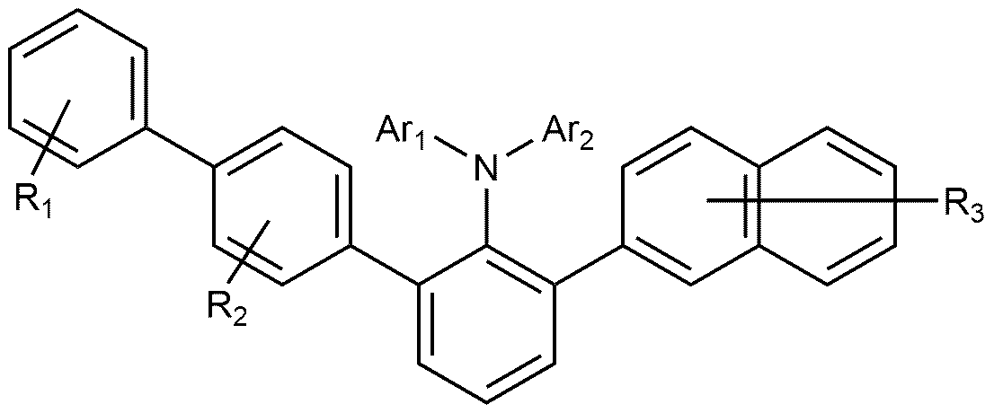
본 발명은 하기 화학식 1로 표시되는 화합물을 제공한다:The present invention provides a compound represented by Formula 1:
[화학식 1][Formula 1]
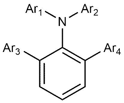
상기 화학식 1에서, In Chemical Formula 1,
Ar1은 및 Ar2는 각각 독립적으로 C6-60 아릴; 또는 N, O 및 S로 구성되는 군으로부터 선택되는 어느 하나 이상의 헤테로원자를 포함하는 치환 또는 비치환된 C5-60 헤테로아릴이고, Ar 1 and Ar 2 are each independently C 6-60 aryl; Or a substituted or unsubstituted C 5-60 heteroaryl containing any one or more heteroatoms selected from the group consisting of N, O and S,
Ar3 및 Ar4는 각각 독립적으로 C6-60 아릴이고, 단, Ar3 및 Ar4가 중 적어도 하나가 비페닐릴 또는 나프틸이다. Ar 3 and Ar 4 are each independently C 6-60 aryl, provided that at least one of Ar 3 and Ar 4 is biphenylyl or naphthyl.
또한, 본 발명은 제1 전극; 상기 제1 전극과 대향하여 구비된 제2 전극; 및 상기 제1 전극과 상기 제2 전극 사이에 구비된 1층 이상의 유기물 층을 포함하는 유기 발광 소자로서, 상기 유기물층 중 1층 이상은 상기 화학식 1로 표시되는 화합물을 포함하는, 유기 발광 소자를 제공한다.In addition, the present invention is a first electrode; A second electrode provided to face the first electrode; And an organic light emitting device including at least one layer of an organic material provided between the first electrode and the second electrode, wherein at least one layer of the organic material layer includes a compound represented by Chemical Formula 1, and provides an organic light emitting device. do.
본 발명에 따른 화합물은 유기 발광 소자의 유기물 층의 재료로서 사용될 수 있으며, 유기 발광 소자에서 효율의 향상, 낮은 구동전압 및/또는 수명 특성을 향상시킬 수 있다. The compound according to the present invention may be used as a material for an organic material layer of an organic light emitting device, and may improve efficiency, low driving voltage, and / or life characteristics in an organic light emitting device.
도 1은 기판(1), 양극(2), 발광층(3), 음극(4)으로 이루어진 유기 발광 소자의 예를 도시한 것이다.
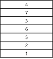
도 2는 기판(1), 양극(2), 정공수송층(5), 전자억제층(6), 발광층(3), 전자수송층(7), 음극(4)으로 이루어진 유기 발광 소자의 예를 도시한 것이다.
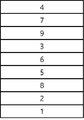
도 3은 기판(1), 양극(2), 정공주입층(8), 정공수송층(5), 전자억제층(6), 발광층(3), 정공억제층(9), 전자수송층(7) 및 음극(4)으로 이루어진 유기 발광 소자의 예를 도시한 것이다.FIG. 1 shows an example of an organic light emitting device including a
FIG. 2 shows an example of an organic light emitting device comprising a
3 shows a
이하, 본 발명의 이해를 돕기 위하여 보다 상세히 설명한다.Hereinafter, the present invention will be described in more detail to help understanding.
본 명세서에서, ![]()
![]()
본 명세서에서 "치환 또는 비치환된" 이라는 용어는 중수소; 할로겐기; 니트릴기; 니트로기; 히드록시기; 카보닐기; 에스테르기; 이미드기; 아미노기; 포스핀옥사이드기; 알콕시기; 아릴옥시기; 알킬티옥시기; 아릴티옥시기; 알킬술폭시기; 아릴술폭시기; 실릴기; 붕소기; 알킬기; 사이클로알킬기; 알케닐기; 아릴기; 아르알킬기; 아르알케닐기; 알킬아릴기; 알킬아민기; 아랄킬아민기; 헤테로아릴아민기; 아릴아민기; 아릴포스핀기; 또는 N, O 및 S 원자 중 1개 이상을 포함하는 헤테로고리기로 이루어진 군에서 선택된 1개 이상의 치환기로 치환 또는 비치환되거나, 상기 예시된 치환기 중 2 이상의 치환기가 연결된 치환 또는 비치환된 것을 의미한다. 예컨대, "2 이상의 치환기가 연결된 치환기"는 비페닐기일 수 있다. 즉, 비페닐기는 아릴기일 수도 있고, 2개의 페닐기가 연결된 치환기로 해석될 수 있다.The term "substituted or unsubstituted" as used herein refers to deuterium; Halogen group; Nitrile group; Nitro group; Hydroxy group; Carbonyl group; Ester groups; Imide group; Amino group; Phosphine oxide group; Alkoxy groups; Aryloxy group; Alkyl thioxy group; Arylthioxy group; Alkyl sulfoxy group; Aryl sulfoxyl group; Silyl group; Boron group; Alkyl groups; Cycloalkyl group; Alkenyl group; Aryl group; Aralkyl group; An alkenyl group; Alkyl aryl groups; Alkylamine groups; Aralkylamine group; Heteroarylamine group; Arylamine group; Arylphosphine group; Or substituted or unsubstituted with one or more substituents selected from the group consisting of heterocyclic groups containing one or more of N, O and S atoms, or substituted or unsubstituted with two or more substituents among the exemplified substituents above . For example, "a substituent having two or more substituents" may be a biphenyl group. That is, the biphenyl group may be an aryl group or may be interpreted as a substituent to which two phenyl groups are connected.
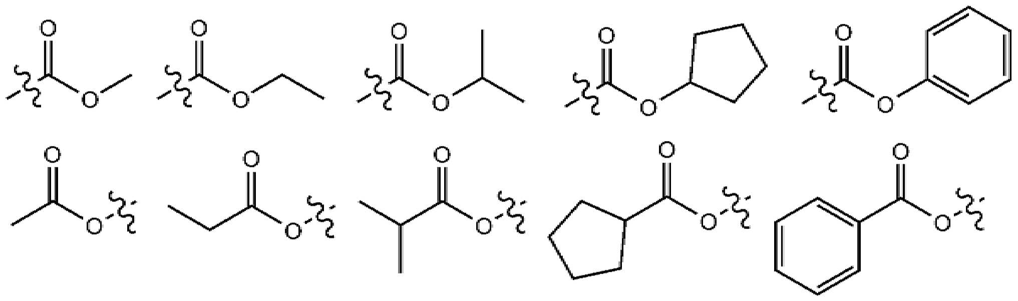
본 명세서에서 카보닐기의 탄소수는 특별히 한정되지 않으나, 탄소수 1 내지 40인 것이 바람직하다. 구체적으로 하기와 같은 구조의 화합물이 될 수 있으나, 이에 한정되는 것은 아니다.In the present specification, the number of carbon atoms of the carbonyl group is not particularly limited, but is preferably 1 to 40 carbon atoms. Specifically, it may be a compound having the following structure, but is not limited thereto.

본 명세서에 있어서, 에스테르기는 에스테르기의 산소가 탄소수 1 내지 25의 직쇄, 분지쇄 또는 고리쇄 알킬기 또는 탄소수 6 내지 25의 아릴기로 치환될 수 있다. 구체적으로, 하기 구조식의 화합물이 될 수 있으나, 이에 한정되는 것은 아니다.In the present specification, the oxygen of the ester group may be substituted with a straight chain, branched or cyclic alkyl group having 1 to 25 carbon atoms or an aryl group having 6 to 25 carbon atoms. Specifically, it may be a compound of the following structural formula, but is not limited thereto.
본 명세서에 있어서, 이미드기의 탄소수는 특별히 한정되지 않으나, 탄소수 1 내지 25인 것이 바람직하다. 구체적으로 하기와 같은 구조의 화합물이 될 수 있으나, 이에 한정되는 것은 아니다.In this specification, the number of carbon atoms of the imide group is not particularly limited, but is preferably 1 to 25 carbon atoms. Specifically, it may be a compound having the following structure, but is not limited thereto.

본 명세서에 있어서, 실릴기는 구체적으로 트리메틸실릴기, 트리에틸실릴기, t-부틸디메틸실릴기, 비닐디메틸실릴기, 프로필디메틸실릴기, 트리페닐실릴기, 디페닐실릴기, 페닐실릴기 등이 있으나 이에 한정되지 않는다. In the present specification, the silyl group is specifically trimethylsilyl group, triethylsilyl group, t-butyldimethylsilyl group, vinyldimethylsilyl group, propyldimethylsilyl group, triphenylsilyl group, diphenylsilyl group, phenylsilyl group, etc. However, it is not limited thereto.
본 명세서에 있어서, 붕소기는 구체적으로 트리메틸붕소기, 트리에틸붕소기, t-부틸디메틸붕소기, 트리페닐붕소기, 페닐붕소기 등이 있으나 이에 한정되지 않는다.In the present specification, the boron group is specifically a trimethyl boron group, a triethyl boron group, a t-butyldimethyl boron group, a triphenyl boron group, a phenyl boron group, and the like, but is not limited thereto.
본 명세서에 있어서, 할로겐기의 예로는 불소, 염소, 브롬 또는 요오드가 있다.In the present specification, examples of the halogen group include fluorine, chlorine, bromine or iodine.
본 명세서에 있어서, 상기 알킬기는 직쇄 또는 분지쇄일 수 있고, 탄소수는 특별히 한정되지 않으나 1 내지 40인 것이 바람직하다. 일 실시상태에 따르면, 상기 알킬기의 탄소수는 1 내지 20이다. 또 하나의 실시상태에 따르면, 상기 알킬기의 탄소수는 1 내지 10이다. 또 하나의 실시상태에 따르면, 상기 알킬기의 탄소수는 1 내지 6이다. 알킬기의 구체적인 예로는 메틸, 에틸, 프로필, n-프로필, 이소프로필, 부틸, n-부틸, 이소부틸, tert-부틸, sec-부틸, 1-메틸-부틸, 1-에틸-부틸, 펜틸, n-펜틸, 이소펜틸, 네오펜틸, tert-펜틸, 헥실, n-헥실, 1-메틸펜틸, 2-메틸펜틸, 4-메틸-2-펜틸, 3,3-디메틸부틸, 2-에틸부틸, 헵틸, n-헵틸, 1-메틸헥실, 사이클로펜틸메틸,사이클로헥틸메틸, 옥틸, n-옥틸, tert-옥틸, 1-메틸헵틸, 2-에틸헥실, 2-프로필펜틸, n-노닐, 2,2-디메틸헵틸, 1-에틸-프로필, 1,1-디메틸-프로필, 이소헥실, 2-메틸펜틸, 4-메틸헥실, 5-메틸헥실 등이 있으나, 이들에 한정되지 않는다.In the present specification, the alkyl group may be straight chain or branched chain, and carbon number is not particularly limited, but is preferably 1 to 40. According to an exemplary embodiment, the alkyl group has 1 to 20 carbon atoms. According to another exemplary embodiment, the alkyl group has 1 to 10 carbon atoms. According to another exemplary embodiment, the alkyl group has 1 to 6 carbon atoms. Specific examples of the alkyl group are methyl, ethyl, propyl, n-propyl, isopropyl, butyl, n-butyl, isobutyl, tert-butyl, sec-butyl, 1-methyl-butyl, 1-ethyl-butyl, pentyl, n -Pentyl, isopentyl, neopentyl, tert-pentyl, hexyl, n-hexyl, 1-methylpentyl, 2-methylpentyl, 4-methyl-2-pentyl, 3,3-dimethylbutyl, 2-ethylbutyl, heptyl , n-heptyl, 1-methylhexyl, cyclopentylmethyl, cyclohexylmethyl, octyl, n-octyl, tert-octyl, 1-methylheptyl, 2-ethylhexyl, 2-propylpentyl, n-nonyl, 2,2 -Dimethylheptyl, 1-ethyl-propyl, 1,1-dimethyl-propyl, isohexyl, 2-methylpentyl, 4-methylhexyl, 5-methylhexyl, and the like, but is not limited thereto.
본 명세서에 있어서, 상기 알케닐기는 직쇄 또는 분지쇄일 수 있고, 탄소수는 특별히 한정되지 않으나, 2 내지 40인 것이 바람직하다. 일 실시상태에 따르면, 상기 알케닐기의 탄소수는 2 내지 20이다. 또 하나의 실시상태에 따르면, 상기 알케닐기의 탄소수는 2 내지 10이다. 또 하나의 실시상태에 따르면, 상기 알케닐기의 탄소수는 2 내지 6이다. 구체적인 예로는 비닐, 1-프로페닐, 이소프로페닐, 1-부테닐, 2-부테닐, 3-부테닐, 1-펜테닐, 2-펜테닐, 3-펜테닐, 3-메틸-1-부테닐, 1,3-부타디에닐, 알릴, 1-페닐비닐-1-일, 2-페닐비닐-1-일, 2,2-디페닐비닐-1-일, 2-페닐-2-(나프틸-1-일)비닐-1-일, 2,2-비스(디페닐-1-일)비닐-1-일, 스틸베닐기, 스티레닐기 등이 있으나 이들에 한정되지 않는다.In the present specification, the alkenyl group may be linear or branched, and the number of carbon atoms is not particularly limited, but is preferably 2 to 40. According to one embodiment, the carbon number of the alkenyl group is 2 to 20. According to another exemplary embodiment, the alkenyl group has 2 to 10 carbon atoms. According to another exemplary embodiment, the alkenyl group has 2 to 6 carbon atoms. Specific examples include vinyl, 1-propenyl, isopropenyl, 1-butenyl, 2-butenyl, 3-butenyl, 1-pentenyl, 2-pentenyl, 3-pentenyl, 3-methyl-1- Butenyl, 1,3-butadienyl, allyl, 1-phenylvinyl-1-yl, 2-phenylvinyl-1-yl, 2,2-diphenylvinyl-1-yl, 2-phenyl-2- ( Naphthyl-1-yl) vinyl-1-yl, 2,2-bis (diphenyl-1-yl) vinyl-1-yl, steelbenyl group, styrenyl group, and the like, but are not limited thereto.
본 명세서에 있어서, 사이클로알킬기는 특별히 한정되지 않으나, 탄소수 3 내지 60인 것이 바람직하며, 일 실시상태에 따르면, 상기 사이클로알킬기의 탄소수는 3 내지 30이다. 또 하나의 실시상태에 따르면, 상기 사이클로알킬기의 탄소수는 3 내지 20이다. 또 하나의 실시상태에 따르면, 상기 사이클로알킬기의 탄소수는 3 내지 6이다. 구체적으로 사이클로프로필, 사이클로부틸, 사이클로펜틸, 3-메틸사이클로펜틸, 2,3-디메틸사이클로펜틸, 사이클로헥실, 3-메틸사이클로헥실, 4-메틸사이클로헥실, 2,3-디메틸사이클로헥실, 3,4,5-트리메틸사이클로헥실, 4-tert-부틸사이클로헥실, 사이클로헵틸, 사이클로옥틸 등이 있으나, 이에 한정되지 않는다.In the present specification, the cycloalkyl group is not particularly limited, but preferably has 3 to 60 carbon atoms, and according to an exemplary embodiment, the cycloalkyl group has 3 to 30 carbon atoms. According to another exemplary embodiment, the cycloalkyl group has 3 to 20 carbon atoms. According to another exemplary embodiment, the cycloalkyl group has 3 to 6 carbon atoms. Specifically, cyclopropyl, cyclobutyl, cyclopentyl, 3-methylcyclopentyl, 2,3-dimethylcyclopentyl, cyclohexyl, 3-methylcyclohexyl, 4-methylcyclohexyl, 2,3-dimethylcyclohexyl, 3, 4,5-trimethylcyclohexyl, 4-tert-butylcyclohexyl, cycloheptyl, cyclooctyl, and the like, but is not limited thereto.
본 명세서에 있어서, 아릴기는 특별히 한정되지 않으나 탄소수 6 내지 60인 것이 바람직하며, 단환식 아릴기 또는 다환식 아릴기일 수 있다. 일 실시상태에 따르면, 상기 아릴기의 탄소수는 6 내지 30이다. 일 실시상태에 따르면, 상기 아릴기의 탄소수는 6 내지 20이다. 상기 아릴기가 단환식 아릴기로는 페닐기, 비페닐릴기, 터페닐기, 쿼터페닐기 등이 될 수 있으나, 이에 한정되는 것은 아니다. 상기 다환식 아릴기로는 나프틸기, 안트라세닐기, 페난트레닐기, 트리페닐레닐기, 파이레닐기, 페릴레닐기, 크라이세닐기, 플루오레닐기 등이 될 수 있으나, 이에 한정되는 것은 아니다.In the present specification, the aryl group is not particularly limited, but is preferably 6 to 60 carbon atoms, and may be a monocyclic aryl group or a polycyclic aryl group. According to one embodiment, the carbon number of the aryl group is 6 to 30. According to one embodiment, the carbon number of the aryl group is 6 to 20. The aryl group may be a phenyl group, a biphenylyl group, a terphenyl group, a quarterphenyl group, etc., as a monocyclic aryl group, but is not limited thereto. The polycyclic aryl group may be a naphthyl group, anthracenyl group, phenanthrenyl group, triphenylenyl group, pyrenyl group, perylenyl group, chrysenyl group, fluorenyl group, and the like, but is not limited thereto.
본 명세서에 있어서, 플루오레닐기는 치환될 수 있고, 치환기 2개가 서로 결합하여 스피로 구조를 형성할 수 있다. 상기 플루오레닐기가 치환되는 경우, 
본 명세서에 있어서, 헤테로고리기는 이종 원소로 O, N, Si 및 S 중 1개 이상을 포함하는 헤테로고리기로서, 탄소수는 특별히 한정되지 않으나, 탄소수 2 내지 60인 것이 바람직하다. 헤테로고리기의 예로는 티오펜기, 퓨란기, 피롤기, 이미다졸기, 티아졸기, 옥사졸기, 옥사디아졸기, 트리아졸기, 피리딜기, 비피리딜기, 피리미딜기, 트리아진기, 아크리딜기, 피리다진기, 피라지닐기, 퀴놀리닐기, 퀴나졸린기, 퀴녹살리닐기, 프탈라지닐기, 피리도 피리미디닐기, 피리도 피라지닐기, 피라지노 피라지닐기, 이소퀴놀린기, 인돌기, 카바졸기, 벤조옥사졸기, 벤조이미다졸기, 벤조티아졸기, 벤조카바졸기, 벤조티오펜기, 디벤조티오펜기, 벤조퓨라닐기, 페난트롤린기(phenanthroline), 이소옥사졸릴기, 티아디아졸릴기, 페노티아지닐기 및 디벤조퓨라닐기 등이 있으나, 이들에만 한정되는 것은 아니다.In the present specification, the heterocyclic group is a heterocyclic group containing one or more of O, N, Si, and S as heterogeneous elements, and the number of carbon atoms is not particularly limited, but is preferably 2 to 60 carbon atoms. Examples of the heterocyclic group include thiophene group, furan group, pyrrol group, imidazole group, thiazole group, oxazole group, oxadiazole group, triazole group, pyridyl group, bipyridyl group, pyrimidyl group, triazine group, acridil group , Pyridazine group, pyrazinyl group, quinolinyl group, quinazolinyl group, quinoxalinyl group, phthalazinyl group, pyridopyrimidinyl group, pyrido pyrazinyl group, pyrazino pyrazinyl group, isoquinoline group, indole group , Carbazole group, benzoxazole group, benzoimidazole group, benzothiazole group, benzocarbazole group, benzothiophene group, dibenzothiophene group, benzofuranyl group, phenanthroline, isooxazolyl group, tiadia A sleepy group, a phenothiazinyl group and a dibenzofuranyl group, and the like, but are not limited thereto.
본 명세서에 있어서, 아르알킬기, 아르알케닐기, 알킬아릴기, 아릴아민기 중의 아릴기는 전술한 아릴기의 예시와 같다. 본 명세서에 있어서, 아르알킬기, 알킬아릴기, 알킬아민기 중 알킬기는 전술한 알킬기의 예시와 같다. 본 명세서에 있어서, 헤테로아릴아민 중 헤테로아릴은 전술한 헤테로고리기에 관한 설명이 적용될 수 있다. 본 명세서에 있어서, 아르알케닐기 중 알케닐기는 전술한 알케닐기의 예시와 같다. 본 명세서에 있어서, 아릴렌은 2가기인 것을 제외하고는 전술한 아릴기에 관한 설명이 적용될 수 있다. 본 명세서에 있어서, 헤테로아릴렌은 2가기인 것을 제외하고는 전술한 헤테로고리기에 관한 설명이 적용될 수 있다. 본 명세서에 있어서, 탄화수소 고리는 1가기가 아니고, 2개의 치환기가 결합하여 형성한 것을 제외하고는 전술한 아릴기 또는 사이클로알킬기에 관한 설명이 적용될 수 있다. 본 명세서에 있어서, 헤테로고리는 1가기가 아니고, 2개의 치환기가 결합하여 형성한 것을 제외하고는 전술한 헤테로고리기에 관한 설명이 적용될 수 있다.In the present specification, an aryl group in an aralkyl group, an alkenyl group, an alkylaryl group, and an arylamine group is the same as the exemplified aryl group described above. In the present specification, the alkyl group among the aralkyl group, alkylaryl group, and alkylamine group is the same as the above-described alkyl group. In the present specification, the description of the heteroaryl group among heteroarylamines may be applied. In the present specification, the alkenyl group in the alkenyl group is the same as the exemplified alkenyl group. In the present specification, the description of the aryl group described above may be applied, except that the arylene is a divalent group. In the present specification, the description of the heterocyclic group described above may be applied, except that the heteroarylene is a divalent group. In the present specification, the hydrocarbon ring is not a monovalent group, and a description of the aryl group or cycloalkyl group described above may be applied, except that two substituents are formed by bonding. In the present specification, the heterocycle is not a monovalent group, and the description of the aforementioned heterocyclic group may be applied, except that two substituents are formed by bonding.
본 발명은 상기 화학식 1로 표시되는 화합물을 제공한다. The present invention provides a compound represented by
상기 화학식 1로 표시되는 화합물은 트리아릴아민의 아민 질소 원자에 결합하는 하나의 페닐기에 있어서, 질소 원자에 대해 오르소(ortho) 위치에만 아릴기를 도입하는 것으로, 이러한 치환기 도입에 따라 화합물의 HOMO 및 LUMO 에너지 준위를 조절하여 각 유기물 층과의 에너지 배리어를 조절할 수 있는 우수한 효과를 얻을 수 있다.The compound represented by
구체적으로, Ar1은 및 Ar2는 각각 독립적으로 C6-30 아릴, 또는 C6-28 아릴, 또는 C6-25 아릴이거나, 또는 N, O 및 S로 구성되는 군으로부터 선택되는 어느 하나 이상의 헤테로원자를 포함하는 치환 또는 비치환된 C5-30 헤테로아릴, 또는 C8-20 헤테로아릴, 또는 C12-18 헤테로아릴일 수 있다. 바람직하게는, Ar1 및 Ar2는 각각 독립적으로, 페닐, 비페닐릴, 터페닐릴, 쿼터페닐릴, 나프틸, 페난트레닐, 트리페닐레닐, 디메틸플루오레닐, 디페닐플루오레닐, 디벤조퓨라닐, 디벤조티오페닐, 9-페닐-9H-카바졸릴, 나프틸로 치환된 페닐, 페난트레닐로 치환된 페닐, 또는 트리페닐레닐로 치환된 페닐 중 어느 하나일 수 있다. Specifically, Ar 1 silver and Ar 2 are each independently C 6-30 aryl, or C 6-28 aryl, or C 6-25 aryl, or any one or more selected from the group consisting of N, O and S It may be a substituted or unsubstituted C 5-30 heteroaryl containing heteroatoms, or C 8-20 heteroaryl, or C 12-18 heteroaryl. Preferably, Ar 1 and Ar 2 are each independently phenyl, biphenylyl, terphenylyl, quarterphenylyl, naphthyl, phenanthrenyl, triphenylenyl, dimethylfluorenyl, diphenylfluorenyl, Dibenzofuranyl, dibenzothiophenyl, 9-phenyl-9H-carbazolyl, phenyl substituted with naphthyl, phenyl substituted with phenanthrenyl, or phenyl substituted with triphenylenyl.
구체적으로, Ar3 및 Ar4는 각각 독립적으로 C6-30 아릴, 또는 C6-25 아릴, 또는 C6-18 아릴일 수 있다. 바람직하게는, Ar3 및 Ar4는 각각 독립적으로, 페닐, 비페닐릴, 터페닐릴, 또는 나프틸이다. Specifically, Ar 3 and Ar 4 may each independently be C 6-30 aryl, or C 6-25 aryl, or C 6-18 aryl. Preferably, Ar 3 and Ar 4 are each independently phenyl, biphenylyl, terphenylyl, or naphthyl.
구체적으로, Ar1와 Ar2, 및 Ar3와 Ar4는 각각 서로 동일하거나 서로 상이한 것일 수 있다. Specifically, Ar 1 and Ar 2 , and Ar 3 and Ar 4 may be the same or different from each other.
일 예로, Ar1와 Ar2, 및 Ar3와 Ar4 중 적어도 한 쌍 이상은 서로 동일한 것일 수 있다. 예컨대, Ar1와 Ar2가 서로 동일하고, Ar3와 Ar4은 서로 상이할 수 있다. 또는, Ar1와 Ar2는 서로 상이하며, Ar3와 Ar4가 서로 동일할 수 있다. 또는 Ar1와 Ar2가 서로 동일하고, Ar3와 Ar4도 서로 동일한 것일 수 있다. For example, at least one pair of Ar 1 and Ar 2 , and Ar 3 and Ar 4 may be the same as each other. For example, Ar 1 and Ar 2 are the same as each other, and Ar 3 and Ar 4 may be different from each other. Alternatively, Ar 1 and Ar 2 are different from each other, and Ar 3 and Ar 4 may be identical to each other. Alternatively, Ar 1 and Ar 2 may be identical to each other, and Ar 3 and Ar 4 may be identical to each other.
여기서, Ar1와 Ar2가 서로 동일한 경우, Ar2와 Ar2는 페닐, 비페닐릴, 터페닐릴, 나프틸, 또는 디메틸플루오레닐일 수 있다. Here, when Ar 1 and Ar 2 are the same as each other, Ar 2 and Ar 2 may be phenyl, biphenylyl, terphenylyl, naphthyl, or dimethylfluorenyl.
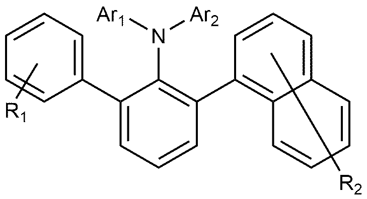
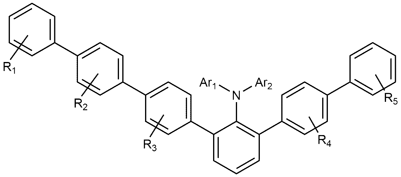
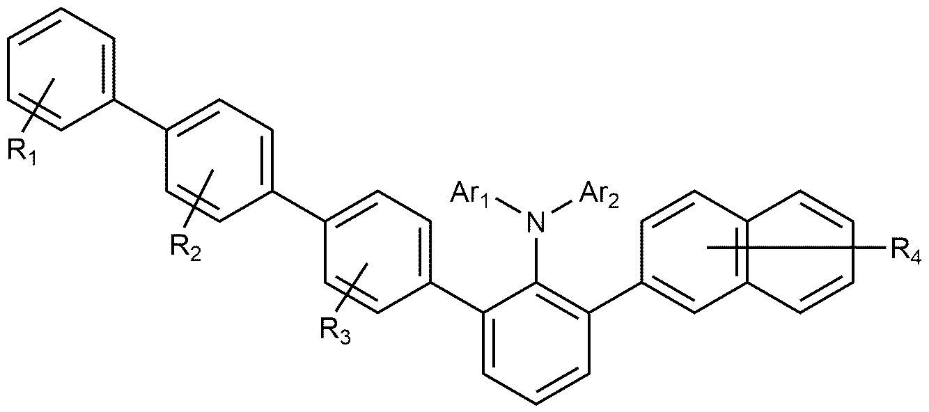
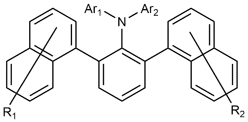
일 예로, 상기 화학식 1로 표시되는 화합물은 하기 화학식 1-1 내지 1-12 중 어느 하나로 표시되는 것일 수 있다. For example, the compound represented by
[화학식 1-1][Formula 1-1]

[화학식 1-2][Formula 1-2]

[화학식 1-3][Formula 1-3]

[화학식 1-4][Formula 1-4]

[화학식 1-5][Formula 1-5]

[화학식 1-6][Formula 1-6]
[화학식 1-7][Formula 1-7]

[화학식 1-8][Formula 1-8]

[화학식 1-9][Formula 1-9]

[화학식 1-10][Formula 1-10]

[화학식 1-11][Formula 1-11]

[화학식 1-12][Formula 1-12]

상기 화학식 1-1 내지 1-12에서, In Chemical Formulas 1-1 to 1-12,
Ar1 및 Ar-2은 상기 화학식 1에서 정의한 바와 같으며, Ar 1 and Ar -2 are as defined in
R1, R2, R3, R4, 및 R5는 각각 독립적으로, 수소, 중수소, 할로겐기, 니트릴기, 실릴기, C6-60 아릴, C6-60 아르알킬, C6-60 아르알케닐; 또는 N, O 및 S로 구성되는 군으로부터 선택되는 어느 하나 이상의 헤테로원자를 포함하는 치환 또는 비치환된 C5-60 헤테로아릴이다. R 1 , R 2 , R 3 , R 4 , and R 5 are each independently hydrogen, deuterium, halogen group, nitrile group, silyl group, C 6-60 aryl, C 6-60 aralkyl, C 6-60 Aralkenyl; Or a substituted or unsubstituted C 5-60 heteroaryl containing any one or more heteroatoms selected from the group consisting of N, O and S.
구체적으로, 상기 R1, R2, R3, R4, 및 R5는 수소일 수 있다. Specifically, R 1 , R 2 , R 3 , R 4 , and R 5 may be hydrogen.
한편, 상기 화학식 1로 표시되는 화합물은, 트리아릴아민의 아민 질소 원자에 치환된 Ar1, Ar2가 회전을 통해 좌우 위치를 달리한 구조 이성질체(stereo-isomer)를 모두 포함하는 것이 될 수 있다. On the other hand, the compound represented by the formula (1), Ar 1 , Ar 2 substituted on the amine nitrogen atom of the triarylamine may be to include all of the structural isomers (stereo-isomer) having a different left and right positions through rotation. .
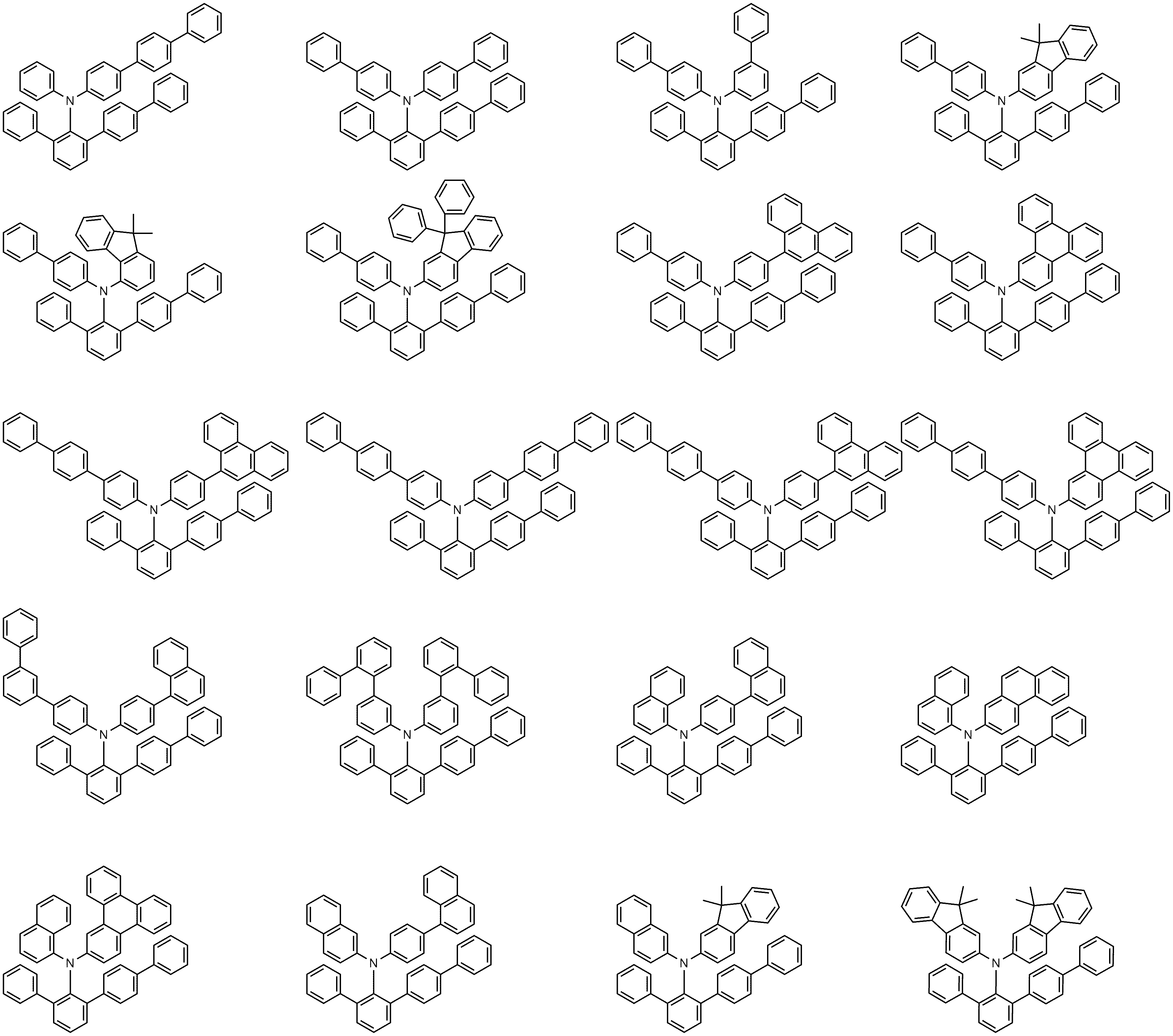
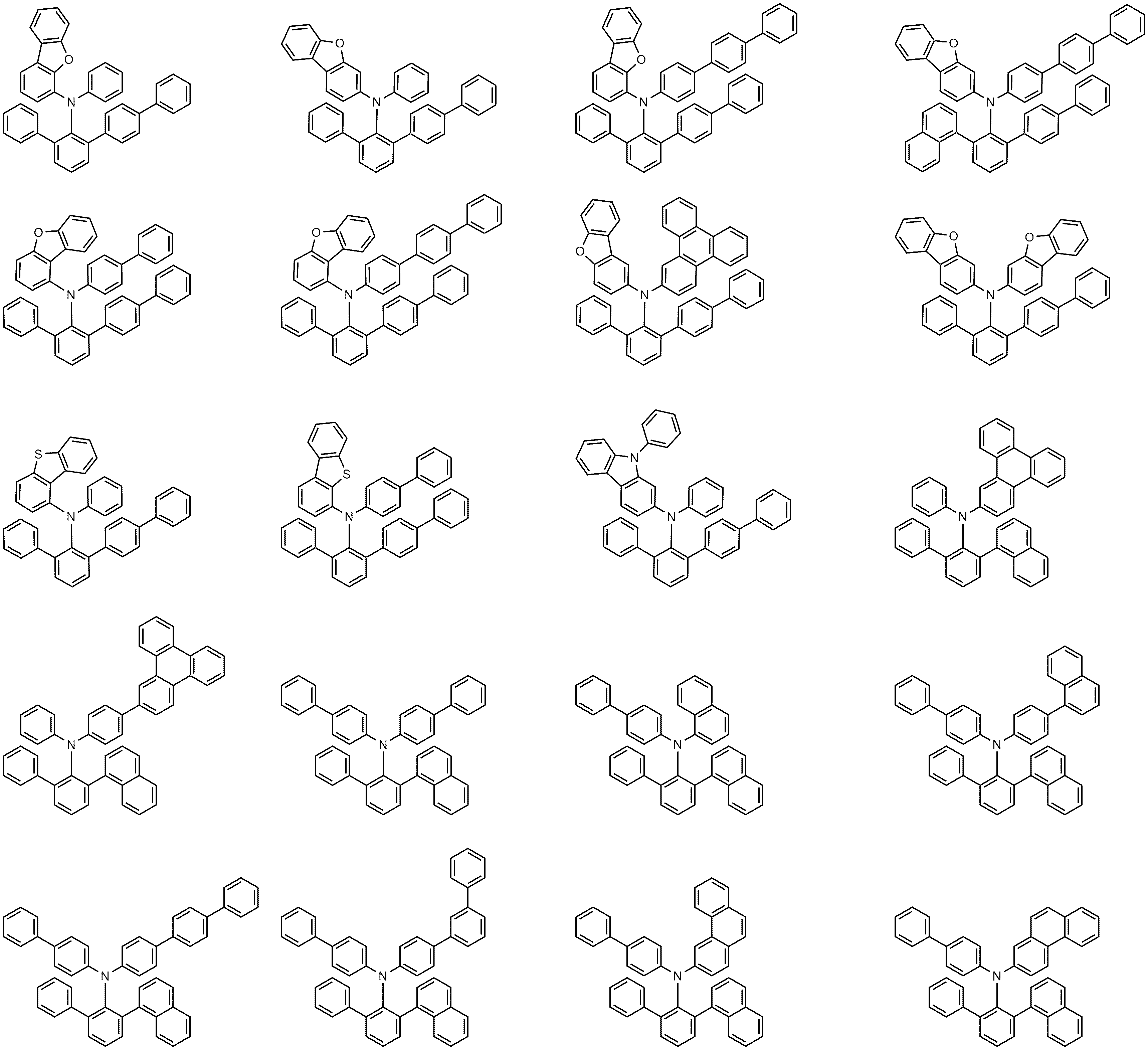
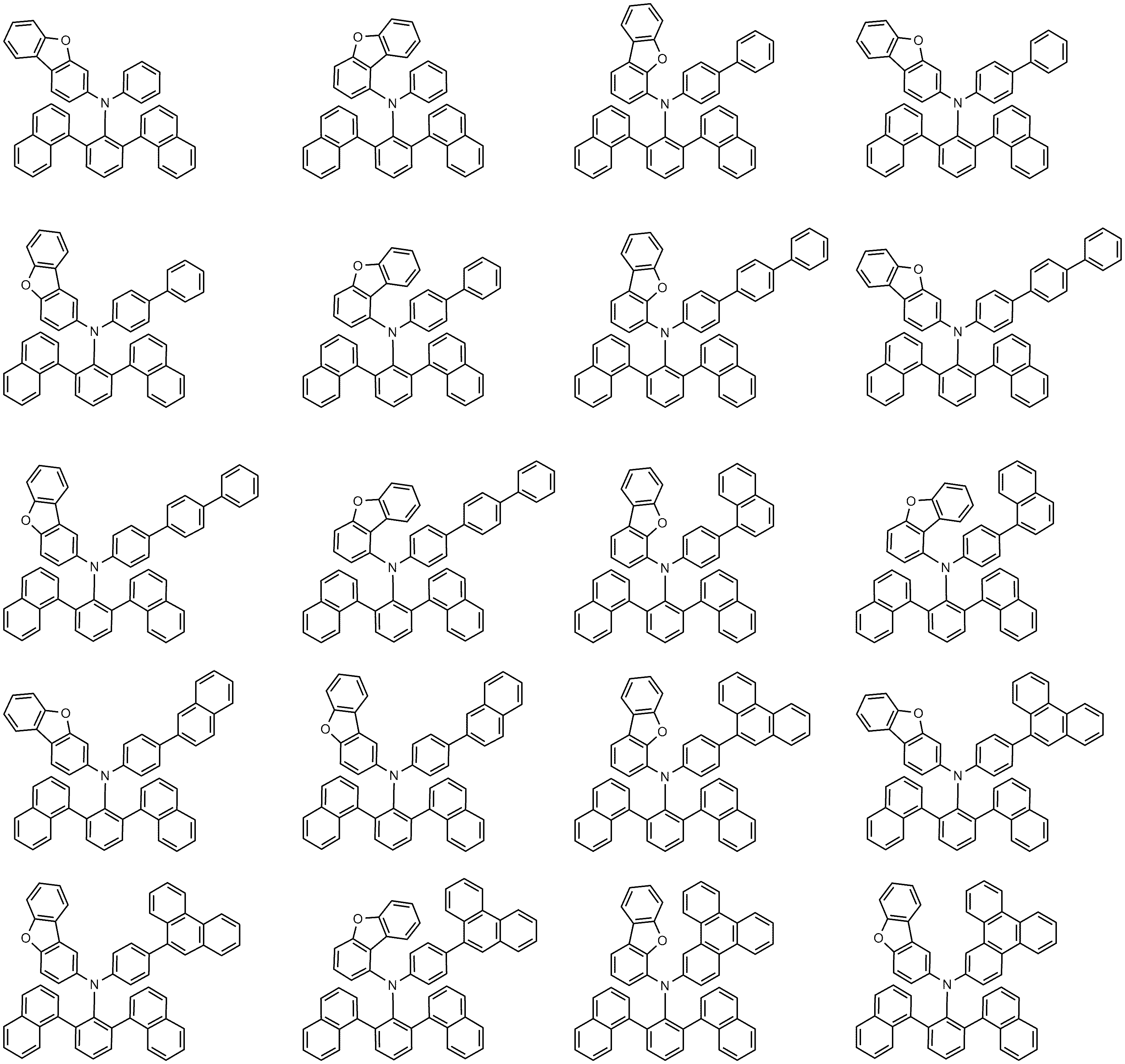
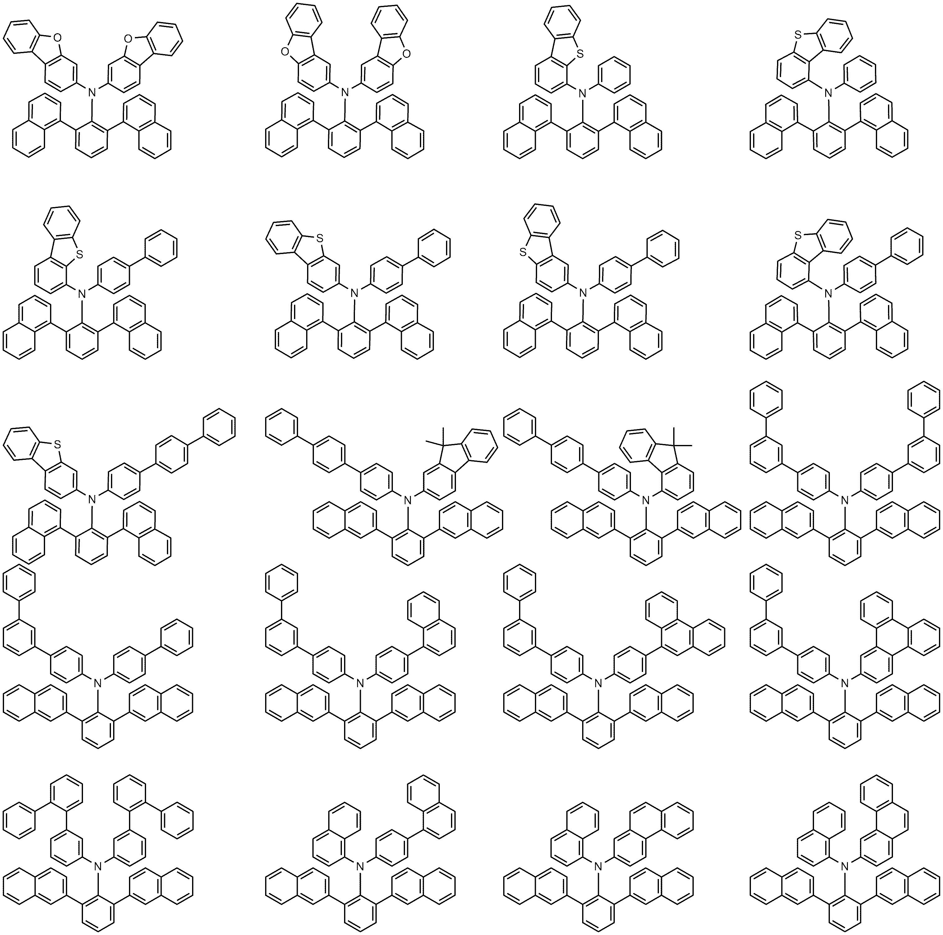
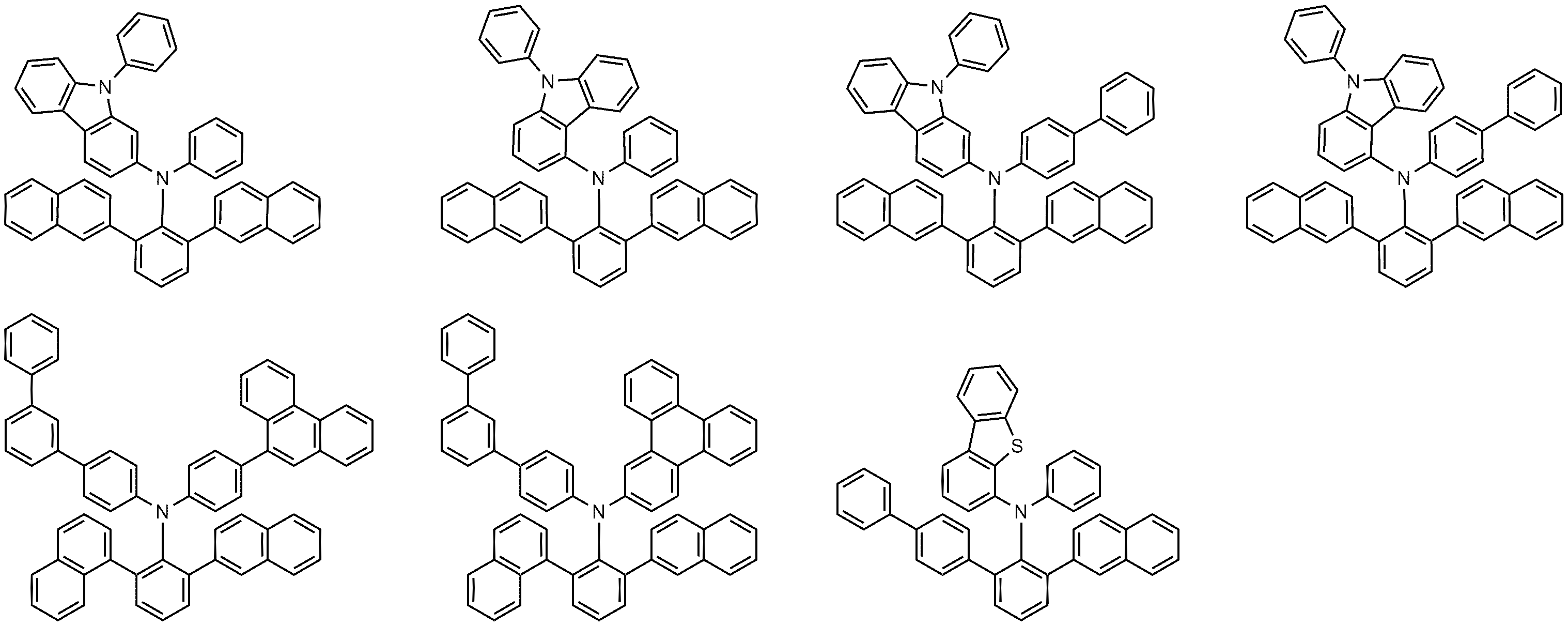
상기 화학식 1로 표시되는 화합물의 대표적인 예는 하기와 같다.Representative examples of the compound represented by


한편, 상기 화학식 1로 표시되는 화합물은 하기 반응식 1 내지 2와 같은 방법으로 제조할 수 있다. Meanwhile, the compound represented by
[반응식 1][Scheme 1]

[반응식 2][Scheme 2]

상기 반응식 1 내지 2에서, Ar1, Ar-2, Ar3, 및 Ar-4는 상기 화학식 1에서 정의한 바와 같으며, X1 내지 X4는 각각 독립적으로 할로겐기이다. In
구체적으로, 상기 반응식 1은, 페닐 아민의 오르소(ortho) 위치의 양쪽에 아릴기(Ar3, Ar4)을 도입하는 반응이다. Specifically,
상기 반응식 1은, 염기(base) 존재 하에서 팔라듐 촉매(Pd catalyst)를 사용하여 수행할 있다. 일예로, 상기 반응식 1에서 염기 성분으로는 포타슘 카보네이트 (K2CO3) 등을 사용할 수 있으며, 팔라듐 촉매로는 비스(트리-터트-부틸포스핀)팔라듐 (BTP, bis(tri-tert-butylphosphine)palladium) 등을 사용할 수 있다.
상기 반응식 1 중 반응 (I)은 페닐 아민의 오르소(ortho) 위치 중 하나에 아릴기를 도입하는 반응으로, 오르소(ortho) 위치에 할로겐기가 치환된 페닐 아민을 염기(base) 존재 하에서 팔라듐 촉매(Pd catalyst)를 사용하여 아릴 보론산(Ar3-B(OH)2)과 반응시키는 것으로 이뤄진다. 이렇게 페닐 아민의 오르소(ortho) 위치 중 하나에 아릴기를 도입한 후에, 상기 반응식 1 중 반응 (II)와 같이 별도의 아릴 보론산(Ar4-B(OH)2)와 반응시켜 페닐 아민의 오르소(ortho) 위치 중 나머지 하나에도 모두 아릴기를 도입하는 것이다. Reaction (I) in
여기서, Ar3와 Ar4가 동일한 경우에는, 상기 반응식 1 중 반응 (II)를 생략하고, 반응(I)에서 페닐 아민의 오르소(ortho) 위치 중 양쪽에 한꺼번에 아릴기를 도입하는 1단계 반응으로 수행할 수 있다. Here, when Ar 3 and Ar 4 are the same, the reaction (II) in the
또한, 상기 반응식 2은, 반응식 1을 통해 생성된 오르소(ortho) 위치에 할로겐기가 치환된 페닐 아민에 아릴이나 헤테로아릴 그룹(Ar1, Ar2)을 추가로 도입하는 반응이다. In addition,
또한, 상기 반응식 2는, 염기(base) 존재 하에서 팔라듐 촉매(Pd catalyst)를 사용하여 수행할 있다. 상기 반응식 2에서 염기 성분으로는 소듐 터트-부톡사이드 (NaOtBu) 등을 사용할 수 있으며, Pd 촉매로는 비스(트리-터트-부틸포스핀)팔라듐 (BTP) 또는 1,1'-비스(디페닐포스피노)페로센디클로로 팔라듐 (II) (Pd(dppf)Cl2) 등을 사용할 수 있다.In addition,
상기 반응식 2 중 반응 (III)은, 상기 반응식 1을 통해 생성된 오르소(ortho) 위치에 할로겐기가 치환된 페닐 아민, 즉, 디아릴 페닐 아민을 염기(base) 존재 하에서 팔라듐 촉매(Pd catalyst)를 사용하여 치환하고자 하는 아릴 또는 헤테로아릴을 포함하는 할로겐화물 (Ar1-X3)과 반응시키는 것으로 이뤄진다. 이렇게 반응 (III)을 통해 디아릴 페닐 아민 중 수소 대신에 아릴이나 헤테로아릴을 도입한 후에, 상기 반응식 1 중 반응 (IV)와 같이 별도의 아릴 또는 헤테로아릴을 포함하는 할로겐화물 (Ar2-X4)과 반응시켜 페닐 아민의 나머지 수소 대신에 모두 아릴 또는 헤테로아릴을 도입하는 것이다. 바람직하게는, X3 및 X4는 각각 독립적으로 브로모 또는 클로롤이다. Reaction (III) in
여기서, Ar1과 Ar2가 동일한 경우에는, 상기 반응식 2 중 반응 (IV)를 생략하고, 반응(III)에서 디아릴 페닐 아민의 수소 2개 대신에 아릴 또는 헤테로아릴을 양쪽에 한꺼번에 도입하는 1 단계 반응으로 수행할 수 있다. Here, when Ar 1 and Ar 2 are the same, the reaction (IV) is omitted in
상기 반응식 1 내지 2에 따른 제조 방법에서, 아민 치환 반응을 위한 반응기는 당업계에 알려진 바에 따라 변경이 가능하다. 상기 제조 방법은 후술할 제조예에서 보다 구체화될 수 있다. In the manufacturing method according to the
또한, 본 발명은 상기 화학식 1로 표시되는 화합물을 포함하는 유기 발광 소자를 제공한다. 일례로, 본 발명은 제1 전극; 상기 제1 전극과 대향하여 구비된 제2 전극; 및 상기 제1 전극과 상기 제2 전극 사이에 구비된 1층 이상의 유기물 층을 포함하는 유기 발광 소자로서, 상기 유기물층 중 1층 이상은 상기 화학식 1로 표시되는 화합물을 포함하는, 유기 발광 소자를 제공한다. In addition, the present invention provides an organic light emitting device comprising the compound represented by the formula (1). In one example, the present invention is a first electrode; A second electrode provided to face the first electrode; And an organic light emitting device including at least one layer of an organic material provided between the first electrode and the second electrode, wherein at least one layer of the organic material layer includes a compound represented by
본 발명의 유기 발광 소자의 유기물 층은 단층 구조로 이루어질 수도 있으나, 2층 이상의 유기물층이 적층된 다층 구조로 이루어질 수 있다. 예컨대, 본 발명의 유기 발광 소자는 유기물 층으로서 정공주입층, 정공수송층, 전자억제층, 발광층, 정공억제층, 전자수송층, 전자주입층 등을 포함하는 구조를 가질 수 있다. 그러나 유기 발광 소자의 구조는 이에 한정되지 않고 더 적은 수의 유기층을 포함할 수 있다.The organic material layer of the organic light emitting device of the present invention may have a single-layer structure, but may have a multi-layer structure in which two or more organic material layers are stacked. For example, the organic light emitting device of the present invention may have a structure including a hole injection layer, a hole transport layer, an electron suppressing layer, a light emitting layer, a hole suppressing layer, an electron transport layer, an electron injection layer, etc. as an organic material layer. However, the structure of the organic light emitting device is not limited thereto, and may include a smaller number of organic layers.
또한, 상기 유기물 층은 정공주입층, 정공수송층, 또는 정공 주입과 수송을 동시에 하는 층을 포함할 수 있고, 상기 정공주입층, 정공수송층, 또는 정공 주입과 수송을 동시에 하는 층은 상기 화학식 1로 표시되는 화합물을 포함한다. In addition, the organic material layer may include a hole injection layer, a hole transport layer, or a layer that simultaneously performs hole injection and transport, and the hole injection layer, a hole transport layer, or a layer that simultaneously performs hole injection and transport is represented by
또한, 상기 유기물 층은 전자억제층을 포함할 수 있고, 이때, 상기 전자억제층은 상기 발광층에 인접하여 위치하고, 상기 전자억제층은 상기 화학식 1로 표시되는 화합물을 포함한다. In addition, the organic material layer may include an electron suppression layer, wherein the electron suppression layer is located adjacent to the light emitting layer, and the electron suppression layer includes a compound represented by
또한, 상기 유기물 층은 발광층을 포함할 수 있고, 상기 발광층은 상기 화학식 1로 표시되는 화합물을 포함한다. 특히, 본 발명에 따른 화합물은 발광층의 도펀트로 사용할 수 있다.Further, the organic material layer may include a light emitting layer, and the light emitting layer includes a compound represented by
또한, 상기 유기물 층은 정공억제층을 포함할 수 있고, 이때, 상기 정공억제층은 상기 발광층에 인접하여 위치하고, 상기 정공억제층은 상기 화학식 1로 표시되는 화합물을 포함한다. In addition, the organic material layer may include a hole suppressing layer, wherein the hole suppressing layer is located adjacent to the light emitting layer, and the hole suppressing layer includes a compound represented by
또한, 상기 유기물 층은 전자수송층, 전자주입층, 또는 전자 주입과 수송을 동시에 하는 층을 포함할 수 있고, 상기 전자수송층, 전자주입층, 또는 전자 주입과 수송을 동시에 하는 층은 상기 화학식 1로 표시되는 화합물을 포함한다. In addition, the organic material layer may include an electron transport layer, an electron injection layer, or a layer that simultaneously performs electron injection and transport, and the electron transport layer, an electron injection layer, or a layer that simultaneously performs electron injection and transport may be represented by
또한, 상기 유기물 층은 정공수송층 및 발광층을 포함하고, 상기 정공수송층은 상기 화학식 1로 표시되는 화합물을 포함할 수 있다. In addition, the organic material layer includes a hole transport layer and a light emitting layer, and the hole transport layer may include a compound represented by
또한, 상기 유기물 층은 전자억제층 및 발광층을 포함하고, 상기 전자억제층은 상기 화학식 1로 표시되는 화합물을 포함할 수 있다. In addition, the organic layer includes an electron suppressing layer and a light emitting layer, and the electron suppressing layer may include a compound represented by
또한, 본 발명에 따른 유기 발광 소자는, 기판 상에 양극, 1층 이상의 유기물 층 및 음극이 순차적으로 적층된 구조(normal type)의 유기 발광 소자일 수 있다. 또한, 본 발명에 따른 유기 발광 소자는 기판 상에 음극, 1층 이상의 유기물 층 및 양극이 순차적으로 적층된 역방향 구조(inverted type)의 유기 발광 소자일 수 있다. 예컨대, 본 발명의 일실시예에 따른 유기 발광 소자의 구조는 도 1 및 2에 예시되어 있다.Further, the organic light emitting device according to the present invention may be an organic light emitting device having a structure in which an anode, one or more organic material layers, and a cathode are sequentially stacked on a substrate. Further, the organic light emitting device according to the present invention may be an organic light emitting device of an inverted type in which a cathode, one or more organic material layers, and an anode are sequentially stacked on a substrate. For example, the structure of the organic light emitting device according to an embodiment of the present invention is illustrated in FIGS. 1 and 2.
도 1은 기판(1), 양극(2), 발광층(3), 음극(4)으로 이루어진 유기 발광 소자의 예를 도시한 것이다. 이와 같은 구조에 있어서, 상기 화학식 1로 표시되는 화합물은 상기 발광층에 포함될 수 있다. FIG. 1 shows an example of an organic light emitting device including a
도 2는 기판(1), 양극(2), 정공수송층(5), 전자억제층(6), 발광층(3), 전자수송층(7), 음극(4)으로 이루어진 유기 발광 소자의 예를 도시한 것이다. 이와 같은 구조에 있어서, 상기 화학식 1로 표시되는 화합물은 상기 정공수송층, 전자억제층, 발광층, 및 전자수송층 중 1층 이상에 포함될 수 있다. FIG. 2 shows an example of an organic light emitting device comprising a
도 3는 기판(1), 양극(2), 정공주입층(8), 정공수송층(5), 전자억제층(6), 발광층(3), 정공억제층(9), 전자수송층(7) 및 음극(4)로 이루어진 유기 발광 소자의 예를 도시한 것이다. 이와 같은 구조에 있어서, 상기 화학식 1로 표시되는 화합물은 상기 정공주입층, 정공수송층, 전자억제층, 발광층, 정공억제층, 및 전자수송층 중 1층 이상에 포함될 수 있다. 3 shows a
본 발명에 따른 유기 발광 소자는, 상기 유기물 층 중 1층 이상이 상기 화학식 1로 표시되는 화합물을 포함하는 것을 제외하고는 당 기술분야에 알려져 있는 재료와 방법으로 제조될 수 있다. 또한, 상기 유기 발광 소자가 복수개의 유기물층을 포함하는 경우, 상기 유기물층은 동일한 물질 또는 다른 물질로 형성될 수 있다. The organic light emitting device according to the present invention may be manufactured by materials and methods known in the art, except that at least one layer of the organic material layer includes the compound represented by
예컨대, 본 발명에 따른 유기 발광 소자는 기판 상에 제1 전극, 유기물층 및 제2 전극을 순차적으로 적층시켜 제조할 수 있다. 이때, 스퍼터링법(sputtering)이나 전자빔 증발법(e-beam evaporation)과 같은 PVD(physical Vapor Deposition)방법을 이용하여, 기판 상에 금속 또는 전도성을 가지는 금속 산화물 또는 이들의 합금을 증착시켜 양극을 형성하고, 그 위에 정공 주입층, 정공 수송층, 전자억제층, 발광층, 정공억제층, 전자 수송층 등을 포함하는 유기물 층을 형성한 후, 그 위에 음극으로 사용할 수 있는 물질을 증착시켜 제조할 수 있다. 이와 같은 방법 외에도, 기판 상에 음극 물질부터 유기물층, 양극 물질을 차례로 증착시켜 유기 발광 소자를 만들 수 있다. For example, the organic light emitting device according to the present invention may be manufactured by sequentially stacking a first electrode, an organic material layer, and a second electrode on a substrate. At this time, a positive electrode is formed by depositing a metal or conductive metal oxide or an alloy thereof on a substrate using a physical vapor deposition (PVD) method such as sputtering or e-beam evaporation. Then, an organic material layer including a hole injection layer, a hole transporting layer, an electron suppressing layer, a light emitting layer, a hole suppressing layer, an electron transporting layer, etc. is formed thereon, and a material that can be used as a cathode is deposited thereon. In addition to this method, an organic light emitting device may be formed by sequentially depositing a cathode material, an organic material layer, and a cathode material on a substrate.
또한, 상기 화학식 1로 표시되는 화합물은 유기 발광 소자의 제조시 진공 증착법 뿐만 아니라 용액 도포법에 의하여 유기물 층으로 형성될 수 있다. 여기서, 용액 도포법이라 함은 스핀 코팅, 딥코팅, 닥터 블레이딩, 잉크젯 프린팅, 스크린 프린팅, 스프레이법, 롤 코팅 등을 의미하지만, 이들만으로 한정되는 것은 아니다.In addition, the compound represented by
이와 같은 방법 외에도, 기판 상에 음극 물질로부터 유기물층, 양극 물질을 차례로 증착시켜 유기 발광 소자를 제조할 수 있다(WO 2003/012890). 다만, 제조 방법이 이에 한정되는 것은 아니다. In addition to this method, an organic light emitting device may be manufactured by sequentially depositing an organic material layer and a cathode material from a cathode material on a substrate (WO 2003/012890). However, the manufacturing method is not limited thereto.
일례로, 상기 제1 전극은 양극이고, 상기 제2 전극은 음극이거나, 또는 상기 제1 전극은 음극이고, 상기 제2 전극은 양극이다.In one example, the first electrode is an anode, the second electrode is a cathode, or the first electrode is a cathode, and the second electrode is an anode.
상기 양극 물질로는 통상 유기물 층으로 정공 주입이 원활할 수 있도록 일함수가 큰 물질이 바람직하다. 상기 양극 물질의 구체적인 예로는 바나듐, 크롬, 구리, 아연, 금과 같은 금속 또는 이들의 합금; 아연 산화물, 인듐 산화물, 인듐주석 산화물(ITO), 인듐아연 산화물(IZO)과 같은 금속 산화물; ZnO:Al 또는 SnO2:Sb와 같은 금속과 산화물의 조합; 폴리(3-메틸티오펜), 폴리[3,4-(에틸렌-1,2-디옥시)티오펜](PEDOT), 폴리피롤 및 폴리아닐린과 같은 전도성 고분자 등이 있으나, 이들에만 한정되는 것은 아니다. The positive electrode material is preferably a material having a large work function so that hole injection into the organic material layer is smooth. Specific examples of the positive electrode material include metals such as vanadium, chromium, copper, zinc and gold or alloys thereof; Metal oxides such as zinc oxide, indium oxide, indium tin oxide (ITO), and indium zinc oxide (IZO); A combination of metal and oxide such as ZnO: Al or SnO 2 : Sb; Conductive polymers such as poly (3-methylthiophene), poly [3,4- (ethylene-1,2-dioxy) thiophene] (PEDOT), polypyrrole, and polyaniline, but are not limited thereto.
상기 음극 물질로는 통상 유기물층으로 전자 주입이 용이하도록 일함수가 작은 물질인 것이 바람직하다. 상기 음극 물질의 구체적인 예로는 마그네슘, 칼슘, 나트륨, 칼륨, 티타늄, 인듐, 이트륨, 리튬, 가돌리늄, 알루미늄, 은, 주석 및 납과 같은 금속 또는 이들의 합금; LiF/Al 또는 LiO2/Al과 같은 다층 구조 물질 등이 있으나, 이들에만 한정되는 것은 아니다. The cathode material is preferably a material having a small work function to facilitate electron injection into the organic material layer. Specific examples of the negative electrode material include metals such as magnesium, calcium, sodium, potassium, titanium, indium, yttrium, lithium, gadolinium, aluminum, silver, tin and lead, or alloys thereof; There is a multilayer structure material such as LiF / Al or LiO 2 / Al, but is not limited thereto.
상기 정공주입층은 전극으로부터 정공을 주입하는 층으로, 정공 주입 물질로는 정공을 수송하는 능력을 가져 양극에서의 정공 주입효과, 발광층 또는 발광재료에 대하여 우수한 정공 주입 효과를 갖고, 발광층에서 생성된 여기자의 전자주입층 또는 전자주입재료에의 이동을 방지하며, 또한, 박막 형성 능력이 우수한 화합물이 바람직하다. 정공 주입 물질의 HOMO(highest occupied molecular orbital)가 양극 물질의 일함수와 주변 유기물 층의 HOMO 사이인 것이 바람직하다. 정공 주입 물질의 구체적인 예로는 금속 포피린(porphyrin), 올리고티오펜, 아릴아민 계열의 유기물, 헥사니트릴헥사아자트리페닐렌 계열의 유기물, 퀴나크리돈(quinacridone)계열의 유기물, 페릴렌(perylene) 계열의 유기물, 안트라퀴논 및 폴리아닐린과 폴리티오펜 계열의 전도성 고분자 등이 있으나, 이들에만 한정 되는 것은 아니다. The hole injection layer is a layer for injecting holes from an electrode, and has the ability to transport holes as a hole injection material, and thus has a hole injection effect at an anode, an excellent hole injection effect for a light emitting layer or a light emitting material, and is produced in the light emitting layer. A compound which prevents migration of the excitons to the electron injection layer or the electron injection material, and which has excellent thin film formation ability is preferable. It is preferable that the highest occupied molecular orbital (HOMO) of the hole injection material is between the work function of the positive electrode material and the HOMO of the surrounding organic material layer. Specific examples of the hole injection material include metal porphyrin, oligothiophene, arylamine-based organic matter, hexanitrile hexaazatriphenylene-based organic matter, quinacridone-based organic matter, and perylene-based Organic materials, anthraquinones, and polyaniline and polythiophene-based conductive polymers, but are not limited thereto.
상기 정공수송층은 정공주입층으로부터 정공을 수취하여 발광층까지 정공을 수송하는 층으로, 정공 수송 물질로 양극이나 정공주입층으로부터 정공을 수송받아 발광층으로 옮겨줄 수 있는 물질로 정공에 대한 이동성이 큰 물질이 적합하다. 구체적인 예로는 아릴아민 계열의 유기물, 전도성 고분자, 및 공액 부분과 비공액 부분이 함께 있는 블록 공중합체 등이 있으나, 이들에만 한정되는 것은 아니다. The hole transport layer is a layer that transports holes from the hole injection layer to the light emitting layer by receiving holes, and is a material that can transport holes to the light emitting layer by receiving holes from the anode or the hole injection layer as a hole transport material and has a large mobility for holes This is suitable. Specific examples include arylamine-based organic materials, conductive polymers, and block copolymers having a conjugated portion and a non-conjugated portion, but are not limited thereto.
상기 전자억제층은 정공수송층 상에 형성되어, 구체적으로 상기 전자억제층은 발광층에 접하여 구비되어, 전자의 과다한 이동을 방지하여 정공-전자간 결합 확률을 높여줌으로써 유기 발광 소자의 효율을 개선하는 역할을 하는 층을 의미한다. 상기 전자억제층은 전자가 발광층에서 이동하지 않도록 전자에 대한 이동성이 작은 물질이 적합하다.The electron suppressing layer is formed on the hole transport layer, specifically, the electron suppressing layer is provided in contact with the light emitting layer, and prevents excessive movement of electrons to increase the probability of hole-electron bonding, thereby improving the efficiency of the organic light emitting device It means the layer to do. The electron suppressing layer is preferably a material having a small mobility for electrons so that the electrons do not move in the light emitting layer.
상기 발광 물질로는 정공수송층과 전자수송층으로부터 정공과 전자를 각각 수송 받아 결합시킴으로써 가시광선 영역의 빛을 낼 수 있는 물질로서, 형광이나 인광에 대한 양자 효율이 좋은 물질이 바람직하다. 구체적인 예로 8-히드록시-퀴놀린 알루미늄 착물(Alq3); 카르바졸 계열 화합물; 이량체화 스티릴(dimerized styryl) 화합물; BAlq; 10-히드록시벤조 퀴놀린-금속 화합물; 벤족사졸, 벤즈티아졸 및 벤즈이미다졸 계열의 화합물; 폴리(p-페닐렌비닐렌)(PPV) 계열의 고분자; 스피로(spiro) 화합물; 폴리플루오렌, 루브렌 등이 있으나, 이들에만 한정되는 것은 아니다. As the light-emitting material, a material capable of emitting light in the visible light region by receiving and bonding holes and electrons from the hole transport layer and the electron transport layer, respectively, is preferably a material having good quantum efficiency for fluorescence or phosphorescence. Specific examples include 8-hydroxy-quinoline aluminum complex (Alq 3 ); Carbazole-based compounds; Dimerized styryl compounds; BAlq; 10-hydroxybenzo quinoline-metal compound; Benzoxazole, benzthiazole and benzimidazole compounds; Poly (p-phenylenevinylene) (PPV) polymers; Spiro compounds; Polyfluorene, rubrene, and the like, but are not limited to these.
상기 발광층은 호스트 재료 및 도펀트 재료를 포함할 수 있다. 호스트 재료는 축합 방향족환 유도체 또는 헤테로환 함유 화합물 등이 있다. 구체적으로 축합 방향족환 유도체로는 안트라센 유도체, 피렌 유도체, 나프탈렌 유도체, 펜타센 유도체, 페난트렌 화합물, 플루오란텐 화합물 등이 있고, 헤테로환 함유 화합물로는 카바졸 유도체, 디벤조퓨란 유도체, 래더형 퓨란 화합물, 피리미딘 유도체 등이 있으나, 이에 한정되지 않는다. The light emitting layer may include a host material and a dopant material. The host material may be a condensed aromatic ring derivative or a heterocyclic compound. Specifically, condensed aromatic ring derivatives include anthracene derivatives, pyrene derivatives, naphthalene derivatives, pentacene derivatives, phenanthrene compounds, fluoranthene compounds, etc., and heterocyclic compounds include carbazole derivatives, dibenzofuran derivatives, and ladder types Furan compounds, pyrimidine derivatives, and the like, but are not limited thereto.
도펀트 재료로는 방향족 아민 유도체, 스트릴아민 화합물, 붕소 착체, 플루오란텐 화합물, 금속 착체 등이 있다. 구체적으로 방향족 아민 유도체로는 치환 또는 비치환된 아릴아미노기를 갖는 축합 방향족환 유도체로서, 아릴아미노기를 갖는 피렌, 안트라센, 크리센, 페리플란텐 등이 있으며, 스티릴아민 화합물로는 치환 또는 비치환된 아릴아민에 적어도 1개의 아릴비닐기가 치환되어 있는 화합물로, 아릴기, 실릴기, 알킬기, 사이클로알킬기 및 아릴아미노기로 이루어진 군에서 1 또는 2 이상 선택되는 치환기가 치환 또는 비치환된다. 구체적으로 스티릴아민, 스티릴디아민, 스티릴트리아민, 스티릴테트라아민 등이 있으나, 이에 한정되지 않는다. 또한, 금속 착체로는 이리듐 착체, 백금 착체 등이 있으나, 이에 한정되지 않는다.Examples of the dopant material include aromatic amine derivatives, strylamine compounds, boron complexes, fluoranthene compounds, and metal complexes. Specifically, the aromatic amine derivative is a condensed aromatic ring derivative having a substituted or unsubstituted arylamino group, and includes arylamino groups such as pyrene, anthracene, chrysene, periplanten, and the substituted or unsubstituted styrylamine compound. A compound in which at least one arylvinyl group is substituted with the arylamine, a substituent selected from 1 or 2 or more from the group consisting of an aryl group, a silyl group, an alkyl group, a cycloalkyl group, and an arylamino group is substituted or unsubstituted. Specifically, styrylamine, styryldiamine, styryltriamine, styryltetraamine, and the like, but are not limited thereto. In addition, examples of the metal complex include an iridium complex and a platinum complex, but are not limited thereto.
상기 정공억제층은 발광층 상에 형성되어, 구체적으로 상기 정공억제층은 발광층에 접하여 구비되어, 정공의 과다한 이동을 방지하여 정공-전자간 결합 확률을 높여줌으로써 유기 발광 소자의 효율을 개선하는 역할을 하는 층을 의미한다. 상기 전자억제층은 정공이 발광층에서 다시 이동하지 않도록 정공에 대한 이동성이 작은 물질이 적합하다.The hole suppressing layer is formed on the light emitting layer, and specifically, the hole suppressing layer is provided in contact with the light emitting layer, thereby preventing excessive movement of holes and increasing the probability of hole-electron bonding, thereby improving the efficiency of the organic light emitting device. It means the floor. The electron suppressing layer is suitable for a material having a small mobility to the hole so that the hole does not move again in the light emitting layer.
상기 전자수송층은 전자주입층으로부터 전자를 수취하여 발광층까지 전자를 수송하는 층으로, 구체적으로, 상기 전자수송층은 상기 정공억제층에 접하여 구비된다. 특히 상기 전자수송층에서 전자 수송 물질로는 음극으로부터 전자를 잘 주입 받아 발광층으로 옮겨줄 수 있는 물질로서, 전자에 대한 이동성이 큰 물질이 적합하다. 구체적인 예로는 8-히드록시퀴놀린의 Al 착물; Alq3를 포함한 착물; 유기 라디칼 화합물; 히드록시플라본-금속 착물 등이 있으나, 이들에만 한정되는 것은 아니다. 전자 수송층은 종래기술에 따라 사용된 바와 같이 임의의 원하는 캐소드 물질과 함께 사용할 수 있다. 특히, 적절한 캐소드 물질의 예는 낮은 일함수를 가지고 알루미늄층 또는 실버층이 뒤따르는 통상적인 물질이다. 구체적으로 세슘, 바륨, 칼슘, 이테르븀 및 사마륨이고, 각 경우 알루미늄 층 또는 실버층이 뒤따른다.The electron transport layer is a layer that receives electrons from the electron injection layer and transports electrons to the light emitting layer. Specifically, the electron transport layer is provided in contact with the hole inhibiting layer. Particularly, as the electron transporting material in the electron transporting layer, a material capable of receiving electrons from the cathode and transferring them to the light emitting layer is suitable. Specific examples include the Al complex of 8-hydroxyquinoline; Complexes including Alq 3 ; Organic radical compounds; Hydroxyflavone-metal complexes, and the like, but are not limited to these. The electron transport layer can be used with any desired cathode material as used according to the prior art. In particular, examples of suitable cathode materials are those that have a low work function and are followed by an aluminum or silver layer. Specifically, cesium, barium, calcium, ytterbium and samarium, each case followed by an aluminum layer or a silver layer.
상기 전자주입층은 전극으로부터 전자를 주입하는 층으로, 전자를 수송하는 능력을 갖고, 음극으로부터의 전자 주입 효과, 발광층 또는 발광 재료에 대하여 우수한 전자주입 효과를 가지며, 발광층에서 생성된 여기자의 정공주입층에의 이동을 방지하고, 또한, 박막형성능력이 우수한 화합물이 바람직하다. 구체적으로는 플루오레논, 안트라퀴노다이메탄, 다이페노퀴논, 티오피란 다이옥사이드, 옥사졸, 옥사다이아졸, 트리아졸, 이미다졸, 페릴렌테트라카복실산, 프레오레닐리덴 메탄, 안트론 등과 그들의 유도체, 금속 착체 화합물 및 질소 함유 5원환 유도체 등이 있으나, 이에 한정되지 않는다. The electron injection layer is a layer that injects electrons from an electrode, has the ability to transport electrons, has an electron injection effect from a cathode, has an excellent electron injection effect on a light emitting layer or a light emitting material, and hole injection of excitons generated in the light emitting layer A compound that prevents migration to the layer and has excellent thin film forming ability is preferred. Specifically, fluorenone, anthraquinodimethane, diphenoquinone, thiopyran dioxide, oxazole, oxadiazole, triazole, imidazole, perylenetetracarboxylic acid, preorenylidene methane, anthrone and the like and their derivatives, metal Complex compounds, nitrogen-containing 5-membered ring derivatives, and the like, but are not limited thereto.
상기 금속 착체 화합물로서는 8-하이드록시퀴놀리나토 리튬, 비스(8-하이드록시퀴놀리나토)아연, 비스(8-하이드록시퀴놀리나토)구리, 비스(8-하이드록시퀴놀리나토)망간, 트리스(8-하이드록시퀴놀리나토)알루미늄, 트리스(2-메틸-8-하이드록시퀴놀리나토)알루미늄, 트리스(8-하이드록시퀴놀리나토)갈륨, 비스(10-하이드록시벤조[h]퀴놀리나토)베릴륨, 비스(10-하이드록시벤조[h]퀴놀리나토)아연, 비스(2-메틸-8-퀴놀리나토)클로로갈륨, 비스(2-메틸-8-퀴놀리나토)(o-크레졸라토)갈륨, 비스(2-메틸-8-퀴놀리나토)(1-나프톨라토)알루미늄, 비스(2-메틸-8-퀴놀리나토)(2-나프톨라토)갈륨 등이 있으나, 이에 한정되지 않는다.Examples of the metal complex compound include 8-hydroxyquinolinato lithium, bis (8-hydroxyquinolinato) zinc, bis (8-hydroxyquinolinato) copper, bis (8-hydroxyquinolinato) manganese, Tris (8-hydroxyquinolinato) aluminum, tris (2-methyl-8-hydroxyquinolinato) aluminum, tris (8-hydroxyquinolinato) gallium, bis (10-hydroxybenzo [h] Quinolinato) beryllium, bis (10-hydroxybenzo [h] quinolinato) zinc, bis (2-methyl-8-quinolinato) chlorogallium, bis (2-methyl-8-quinolinato) ( There are o-cresolato) gallium, bis (2-methyl-8-quinolinato) (1-naphtholato) aluminum, bis (2-methyl-8-quinolinato) (2-naphtholato) gallium, It is not limited to this.
본 발명에 따른 유기 발광 소자는 사용되는 재료에 따라 전면 발광형, 후면 발광형 또는 양면 발광형일 수 있다.The organic light emitting device according to the present invention may be a front emission type, a back emission type, or a double-sided emission type depending on the material used.
또한, 상기 화학식 1로 표시되는 화합물은 유기 발광 소자 외에도 유기 태양 전지 또는 유기 트랜지스터에 포함될 수 있다.In addition, the compound represented by
본 발명에 따른 신규 화합물 및 이를 포함하는 유기 발광 소자의 제조는 이하 실시예에서 구체적으로 설명한다. 그러나 하기 실시예는 본 발명을 예시하기 위한 것이며, 본 발명의 범위가 이들에 의하여 한정되는 것은 아니다.The production of a novel compound according to the present invention and an organic light-emitting device comprising the same will be described in detail in the Examples below. However, the following examples are intended to illustrate the invention, and the scope of the invention is not limited by them.
합성예 1. 화합물 1의 합성Synthesis Example 1. Synthesis of
단계 1) 화합물 1-A의 합성Step 1) Synthesis of Compound 1-A

2,6-디브로모아닐린 (50.0 g, 199.27 mmol)과 [1.1'-바이페닐]-4-일보론 산 (82.87 g, 418.46 mmol)을 이용하여 상기 합성예 1의 단계 1과 동일한 방법으로 상기 화합물 7-A (68.0 g, 85.84% 수율)를 수득하였다.Using 2,6-dibromoaniline (50.0 g, 199.27 mmol) and [1.1'-biphenyl] -4-ylboronic acid (82.87 g, 418.46 mmol) in the same manner as in
2,6-디브로모아닐린 (50.0 g, 199.27 mmol)과 [1.1'-바이페닐]-4-일보론 산 (82.87 g, 418.46 mmol)을 1,4-다이옥산(700 mL)에 용해 후, 포타슘 카보네이트 (130.71 g, 996.35 mmol, 물 350 mL) 용액을 가한 후, 10 분 동안 가열 교반하였다. 상기 용액에 1,4-다이옥산(10 mL)에 용해시킨 비스(트리-터트-부틸포스핀)팔라듐 (BTP, 0.20 g, 0.40 mmol)을 가한 후 1 시간 동안 가열 교반하였다. 반응 종결 및 여과 후, 클로로포름과 물로 층분리하였다. 용매 제거 후 에틸아세테이트로 재결정하여 상기 화합물 1-A (68.0 g, 85.84% 수율)를 수득하였다.After dissolving 2,6-dibromoaniline (50.0 g, 199.27 mmol) and [1.1'-biphenyl] -4-ylboronic acid (82.87 g, 418.46 mmol) in 1,4-dioxane (700 mL), A solution of potassium carbonate (130.71 g, 996.35 mmol, 350 mL water) was added, followed by heating and stirring for 10 minutes. Bis (tri-tert-butylphosphine) palladium (BTP, 0.20 g, 0.40 mmol) dissolved in 1,4-dioxane (10 mL) was added to the solution, followed by heating and stirring for 1 hour. After completion of the reaction and filtration, layer separation was performed with chloroform and water. After removal of the solvent, recrystallization with ethyl acetate gave the compound 1-A (68.0 g, 85.84% yield).
단계 2) 화합물 1-B의 합성Step 2) Synthesis of Compound 1-B
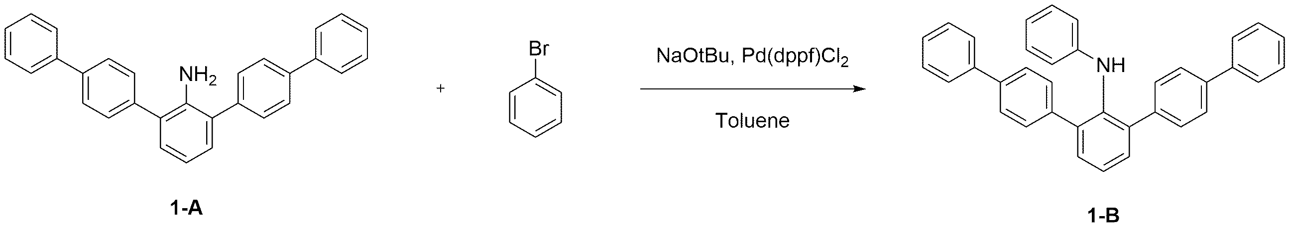
상기 합성예 1의 단계 1에서 수득한 화합물 1-A (40.0 g, 100.63 mmol)와 브로모벤젠 (15.80 g, 100.63 mmol), 그리고 소듐 터트-부톡사이드 (21.94 g, 228.27 mmol)에 톨루엔(250 mL)을 가한 후, 10 분 동안 가열 교반하였다. 상기 혼합물에 톨루엔(30 mL)에 용해시킨 1,1’-비스(디페닐포스피노)페로센디클로로팔라듐(II) (Pd(dppf)Cl2, 0.60 g, 0.82 mmol)을 가한 후 1 시간 동안 가열 교반하였다. 반응 종결 및 여과 후, 톨루엔과 물로 층분리하였다. 용매 제거 후 에틸아세테이트로 재결정하여 상기 화합물 1-B (37.0 g, 77.63% 수율)를 수득하였다.Compound 1-A (40.0 g, 100.63 mmol) obtained in
단계 3) 화합물 1의 합성Step 3) Synthesis of

상기 합성예 1의 단계 2에서 수득한 화합물 1-B (20.0 g, 42.23 mmol)와 4-브로모-1,1':4',1"-터페닐 (13.32 g, 43.07 mmol) 그리고 소듐 터트-부톡사이드 (NaOtBu, 8.37 g, 87.11 mmol)에 자일렌(200 mL)을 가한 후, 10 분 동안 가열 교반하였다. 상기 혼합물에 자일렌(10 mL)에 용해시킨 비스(트리-터트-부틸포스핀)팔라듐 (BTP, 0.16 g, 0.31 mmol)을 가한 후 1 시간 동안 가열 교반하였다. 반응 종결 및 여과 후, 톨루엔과 물로 층분리하였다. 용매 제거 후 에틸아세테이트로 재결정하여 상기 화합물 1 (21.0 g, 79.46% 수율)을 수득하였다. (MS[M+H]+ = 626)Compound 1-B (20.0 g, 42.23 mmol) obtained in
합성예 2. 화합물 2의 합성Synthesis Example 2. Synthesis of
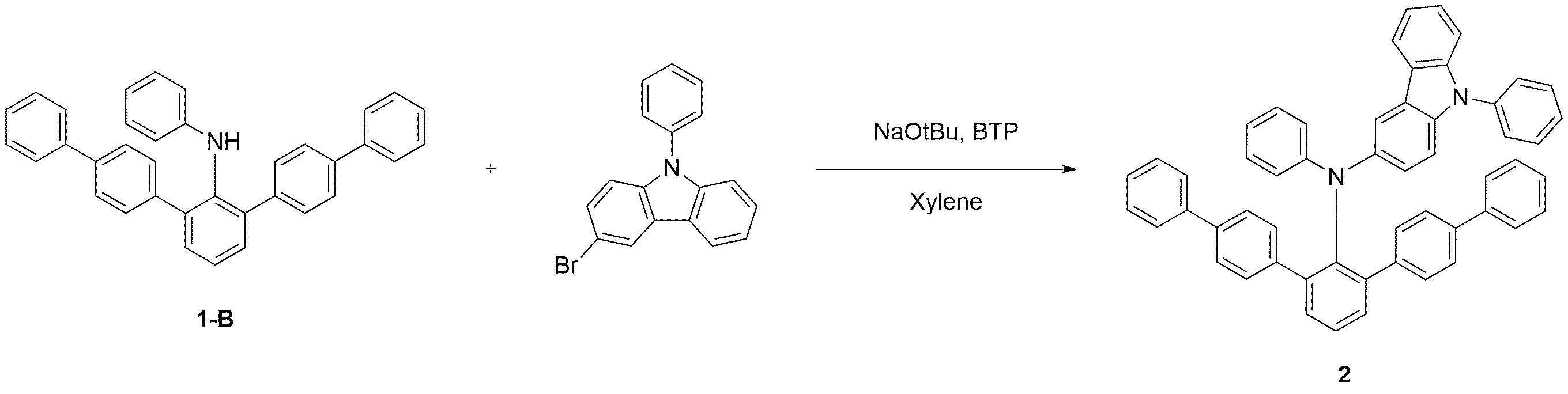
상기 합성예 1의 단계 2에서 수득한 화합물 1-B (20.0 g, 42.23 mmol)와 3-브로모-9-페닐-9H-카바졸 (13.88 g, 43.07 mmol)을 이용하여 상기 합성예 1의 단계 3과 동일한 방법으로 상기 화합물 2 (21.5 g, 79.70% 수율)를 수득하였다. (MS[M+H]+ = 639)Synthesis Example 1 using Compound 1-B (20.0 g, 42.23 mmol) and 3-bromo-9-phenyl-9 H -carbazole (13.88 g, 43.07 mmol) obtained in
합성예 3. 화합물 3의 합성Synthesis Example 3. Synthesis of
단계 1) 화합물 3-A의 합성Step 1) Synthesis of Compound 3-A

상기 합성예 1의 단계 1에서 수득한 화합물 1-A (40.0 g, 100.63 mmol)와 4-브로모-1.1'-바이페닐 (23.46 g, 100.63 mmol)을 이용하여 상기 합성예 1의 단계 2와 동일한 방법으로 상기 화합물 3-A (47.7 g, 86.23% 수율)를 수득하였다.Using compound 1-A (40.0 g, 100.63 mmol) and 4-bromo-1.1'-biphenyl (23.46 g, 100.63 mmol) obtained in
단계 2) 화합물 3의 합성Step 2) Synthesis of

상기 합성예 3의 단계 1에서 수득한 화합물 3-A (20.0 g, 36.38 mmol)와 1-브로모디벤조[b,d]퓨란 (9.17 g, 37.11 mmol)을 이용하여 상기 합성예 1의 단계 3과 동일한 방법으로 상기 화합물 3 (19.5 g, 74.87% 수율)을 수득하였다. (MS[M+H]+ = 716)
합성예 4. 화합물 4의 합성Synthesis Example 4. Synthesis of

상기 합성예 3의 단계 1에서 수득한 화합물 3-A (20.0 g, 36.38 mmol)와 2-브로모디벤조[b,d]사이오펜 (9.77 g, 37.11 mmol)을 이용하여 상기 합성예 1의 단계 3과 동일한 방법으로 상기 화합물 4 (20.4 g, 76.61% 수율)를 수득하였다. (MS[M+H]+ = 732)Step of Synthesis Example 1 using compound 3-A (20.0 g, 36.38 mmol) and 2-bromodibenzo [ b, d ] thiophene (9.77 g, 37.11 mmol) obtained in
합성예 5. 화합물 5의 합성Synthesis Example 5. Synthesis of
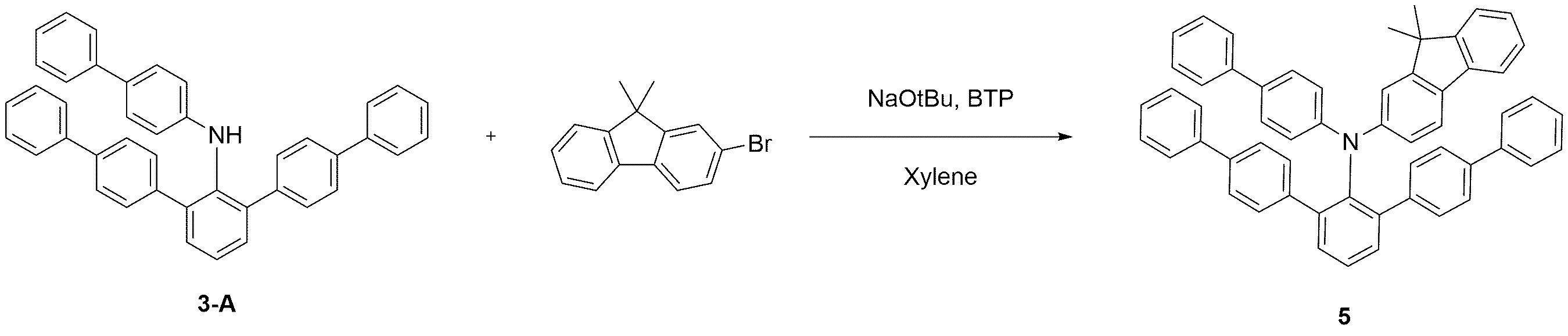
상기 합성예 3의 단계 1에서 수득한 화합물 3-A (20.0 g, 36.38 mmol)와 2-브로모-9,9-디메틸-9H-플루오렌 (10.14 g, 37.11 mmol)을 이용하여 상기 합성예 1의 단계 3과 동일한 방법으로 상기 화합물 5 (21.7 g, 80.40% 수율)를 수득하였다. (MS[M+H]+ = 742)Synthesis using compound 3-A (20.0 g, 36.38 mmol) and 2-bromo-9,9-dimethyl-9 H -fluorene (10.14 g, 37.11 mmol) obtained in
합성예 6. 화합물 6의 합성Synthesis Example 6. Synthesis of

상기 합성예 1의 단계 1에서 수득한 화합물 1-A (15.0 g, 37.73 mmol)와 2-브로모나프탈렌 (16.02 g, 77.35 mmol) 그리고 소듐 터트-부톡사이드 (16.45 g, 171.19 mmol)에 자일렌(200 mL)을 가한 후, 10분 동안 가열 교반하였다. 상기 혼합물에 자일렌(15 mL)에 용해시킨 비스(트리-터트-부틸포스핀)팔라듐 (0.25 g, 0.49 mmol)을 가한 후 1 시간 동안 가열 교반하였다. 반응 종결 및 여과 후, 톨루엔과 물로 층분리하였다. 용매 제거 후 에틸아세테이트로 재결정하여 상기 화합물 6 (20.5 g, 83.61% 수율)을 수득하였다. (MS[M+H]+ = 650)Compound 1-A (15.0 g, 37.73 mmol) obtained in
합성예 7. 화합물 7의 합성Synthesis Example 7. Synthesis of

상기 합성예 1의 단계 1에서 수득한 화합물 1-A (15.0 g, 37.73 mmol)와 4-브로모-1.1'-바이페닐 (18.03 g, 77.35 mmol)을 이용하여 상기 합성예 6과 동일한 방법으로 상기 화합물 7 (22.5 g, 84.96% 수율)을 수득하였다. (MS[M+H]+ = 702)Using Compound 1-A (15.0 g, 37.73 mmol) and 4-bromo-1.1'-biphenyl (18.03 g, 77.35 mmol) obtained in
합성예 8. 화합물 8의 합성Synthesis Example 8. Synthesis of

상기 합성예 1의 단계 1에서 수득한 화합물 1-A (15.0 g, 37.73 mmol)와 2-브로모-9,9-디메틸-9H-플루오렌 (21.13 g, 77.35 mmol)을 이용하여 상기 합성예 6과 동일한 방법으로 상기 화합물 8 (23.4 g, 79.30% 수율)을 수득하였다. (MS[M+H]+ = 782)Synthesis using Compound 1-A (15.0 g, 37.73 mmol) and 2-bromo-9,9-dimethyl-9 H -fluorene (21.13 g, 77.35 mmol) obtained in
합성예 9. 화합물 9의 합성Synthesis Example 9. Synthesis of Compound 9
단계 1) 화합물 9-A의 합성Step 1) Synthesis of Compound 9-A
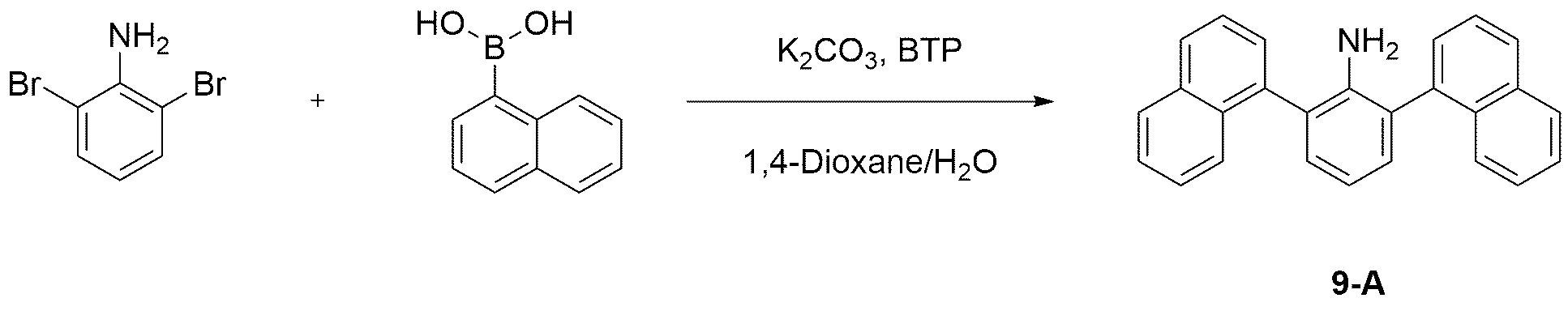
2,6-디브로모아닐린 (50.0 g, 199.27 mmol)과 나프탈렌-1-일보론 산 (71.97 g, 418.46 mmol)을 이용하여 상기 합성예 1의 단계 1과 동일한 방법으로 상기 화합물 9-A (52.0 g, 75.54% 수율)를 수득하였다.Compound 9-A in the same manner as in
단계 2) 화합물 9-B의 합성Step 2) Synthesis of Compound 9-B

상기 합성예 9의 단계 1에서 수득한 화합물 9-A (40.0 g, 115.79 mmol)와 4-브로모-1.1'-바이페닐 (26.99 g, 115.79 mmol)을 이용하여 상기 합성예 1의 단계 2와 동일한 방법으로 상기 화합물 9-B (46.1 g, 80.00% 수율)를 수득하였다.Using compound 9-A (40.0 g, 115.79 mmol) and 4-bromo-1.1'-biphenyl (26.99 g, 115.79 mmol) obtained in
단계 3) 화합물 9의 합성Step 3) Synthesis of Compound 9
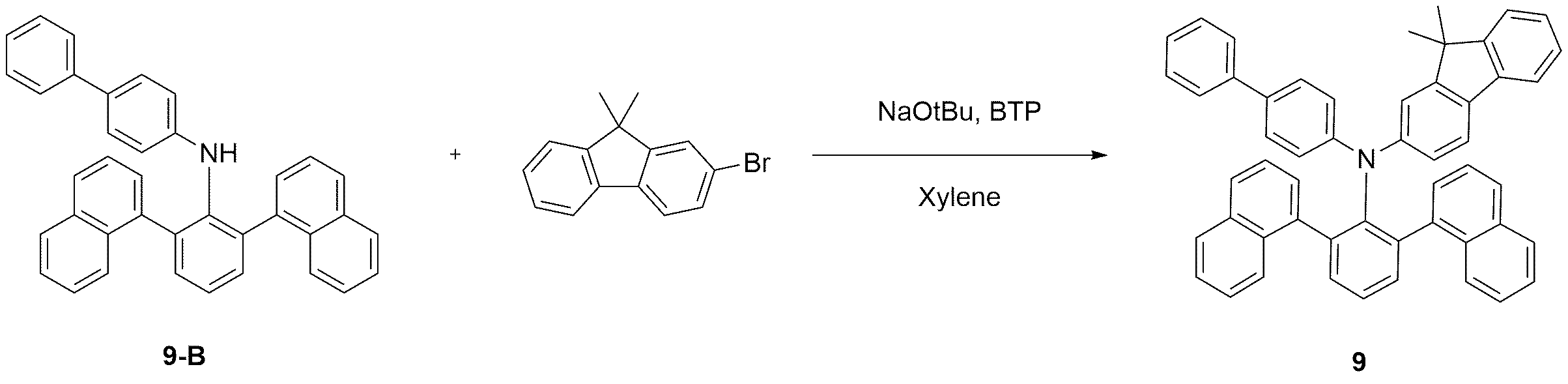
상기 합성예 9의 단계 2에서 수득한 화합물 9-B (20.0 g, 40.19 mmol)와 2-브로모-9,9-디메틸-9H-플루오렌 (11.20 g, 40.99 mmol)을 이용하여 상기 합성예 1의 단계 3과 동일한 방법으로 상기 화합물 9 (21.8 g, 78.62% 수율)를 수득하였다. (MS[M+H]+ = 690)Synthesis using Compound 9-B (20.0 g, 40.19 mmol) and 2-bromo-9,9-dimethyl-9 H -fluorene (11.20 g, 40.99 mmol) obtained in
합성예 10. 화합물 10의 합성Synthesis Example 10. Synthesis of Compound 10
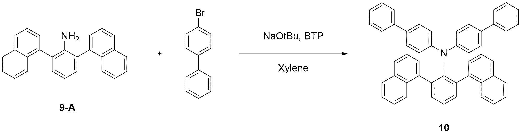
상기 합성예 9의 단계 1에서 수득한 화합물 9-A (15.0 g, 43.42 mmol)와 4-브로모-1.1'-바이페닐 (20.75 g, 89.01 mmol)을 이용하여 상기 합성예 6과 동일한 방법으로 상기 화합물 10 (22.7 g, 80.45% 수율)을 수득하였다. (MS[M+H]+ = 650)Using the compound 9-A (15.0 g, 43.42 mmol) and 4-bromo-1.1'-biphenyl (20.75 g, 89.01 mmol) obtained in
합성예 11. 화합물 11의 합성Synthesis Example 11. Synthesis of Compound 11
단계 1) 화합물 11-A의 합성Step 1) Synthesis of Compound 11-A

2,6-디브로모아닐린 (50.0 g, 199.27 mmol)과 나프탈렌-2-일보론 산 (71.97 g, 418.46 mmol)을 이용하여 상기 합성예 1의 단계 1과 동일한 방법으로 상기 화합물 11-A (56.0 g, 81.35% 수율)를 수득하였다.Compound 11-A in the same manner as in
단계 2) 화합물 11-B의 합성Step 2) Synthesis of Compound 11-B

상기 합성예 11의 단계 1에서 수득한 화합물 11-A (40.0 g, 115.79 mmol)와 4-브로모-1.1'-바이페닐 (26.99 g, 115.79 mmol)을 이용하여 상기 합성예 1의 단계 2와 동일한 방법으로 상기 화합물 11-B (48.3 g, 83.82% 수율)를 수득하였다.Using compound 11-A (40.0 g, 115.79 mmol) and 4-bromo-1.1'-biphenyl (26.99 g, 115.79 mmol) obtained in
단계 3) 화합물 11의 합성Step 3) Synthesis of Compound 11

상기 합성예 11의 단계 2에서 수득한 화합물 11-B (20.0 g, 40.19 mmol)와 2-브로모-9,9-디메틸-9H-플루오렌 (11.20 g, 40.99 mmol)을 이용하여 상기 합성예 1의 단계 3과 동일한 방법으로 상기 화합물 11 (22.8 g, 82.23% 수율)을 수득하였다. (MS[M+H]+ = 690)Synthesis using Compound 11-B (20.0 g, 40.19 mmol) obtained in
합성예 12. 화합물 12의 합성Synthesis Example 12. Synthesis of Compound 12
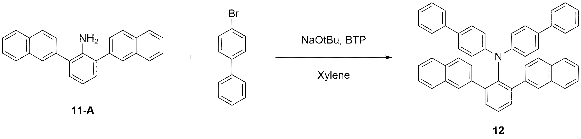
상기 합성예 11의 단계 1에서 수득한 화합물 11-A (15.0 g, 43.42 mmol)와 4-브로모-1.1'-바이페닐 (20.75 g, 89.01 mmol)을 이용하여 상기 합성예 6과 동일한 방법으로 상기 화합물 12 (23.8 g, 84.35% 수율)를 수득하였다. (MS[M+H]+ = 650)Using Compound 11-A (15.0 g, 43.42 mmol) and 4-bromo-1.1'-biphenyl (20.75 g, 89.01 mmol) obtained in
합성예 13. 화합물 13의 합성Synthesis Example 13. Synthesis of Compound 13
단계 1) 화합물 13-A의 합성Step 1) Synthesis of Compound 13-A

2-브로모-6-클로로아닐린 (50.0 g, 242.17 mmol)과 페닐보론 산 (31.00 g, 254.27 mmol)을 1,4-다이옥산(600 mL)에 용해 후, 포타슘 카보네이트 (100.41 g, 726.51 mmol : 물 300 mL) 용액을 가한 후, 10분 동안 가열 교반하였다. 상기 용액에 1,4-다이옥산(50 mL)에 용해시킨 1,1'-비스(디페닐포스피노)페로센디클로로팔라듐(II) (0.89 g, 1.21 mmol)을 가한 후 1 시간 동안 가열 교반하였다. 반응 종결 및 여과 후, 클로로포름과 물로 층분리하였다. 용매 제거 후 에틸아세테이트로 재결정하여 상기 화합물 13-A (40.0 g, 81.10% 수율)를 수득하였다.After dissolving 2-bromo-6-chloroaniline (50.0 g, 242.17 mmol) and phenylboronic acid (31.00 g, 254.27 mmol) in 1,4-dioxane (600 mL), potassium carbonate (100.41 g, 726.51 mmol): Water 300 mL) solution was added, followed by heating and stirring for 10 minutes. To the solution, 1,1'-bis (diphenylphosphino) ferrocenedichloropalladium (II) (0.89 g, 1.21 mmol) dissolved in 1,4-dioxane (50 mL) was added, followed by heating and stirring for 1 hour. After completion of the reaction and filtration, layer separation was performed with chloroform and water. After removal of the solvent, recrystallization with ethyl acetate gave the compound 13-A (40.0 g, 81.10% yield).
단계 2) 화합물 13-B의 합성Step 2) Synthesis of Compound 13-B

상기 합성예 13의 단계 1에서 수득한 화합물 13-A (40.0 g, 196.40 mmol)와 [1.1'-바이페닐]-4-일보론 산 (40.84 g, 206.22 mmol)을 1,4-다이옥산(500 mL)에 용해 후, 포타슘 카보네이트 (81.43 g, 589.20 mmol : 물 250 mL) 용액을 가한 후, 10 분 동안 가열 교반하였다. 상기 용액에 1,4-다이옥산(25 mL)에 용해시킨 비스(트리-터트-부틸포스핀)팔라듐 (0.50 g, 0.98 mmol)을 가한 후 1 시간 동안 가열 교반하였다. 반응 종결 및 여과 후, 클로로포름과 물로 층분리하였다. 용매 제거 후 에틸아세테이트로 재결정하여 상기 화합물 13-B (48.0 g, 76.04% 수율)를 수득하였다.Compound 13-A (40.0 g, 196.40 mmol) and [1.1'-biphenyl] -4-ylboronic acid (40.84 g, 206.22 mmol) obtained in
단계 3) 화합물 13의 합성Step 3) Synthesis of Compound 13
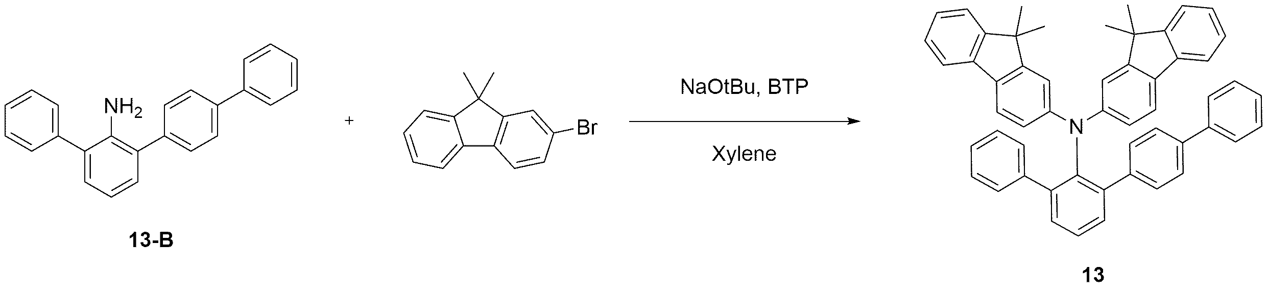
상기 합성예 13의 단계 2에서 수득한 화합물 13-B (15.0 g, 46.67 mmol)와 2-브로모-9,9-디메틸-9H-플루오렌 (26.13 g, 95.67 mmol)을 이용하여 상기 합성예 6과 동일한 방법으로 상기 화합물 13 (26.4 g, 78.92% 수율)을 수득하였다. (MS[M+H]+ = 706)Synthesis using Compound 13-B (15.0 g, 46.67 mmol) obtained in
합성예 14. 화합물 14의 합성Synthesis Example 14. Synthesis of Compound 14
단계 1) 화합물 14-A의 합성Step 1) Synthesis of Compound 14-A

상기 합성예 13의 단계 1에서 수득한 화합물 13-A (40.0 g, 196.40 mmol)와 나프탈렌-1-일보론 산 (35.47 g, 206.22 mmol)을 이용하여 상기 합성예 13의 단계 2와 동일한 방법으로 상기 화합물 14-A (45.0 g, 77.57% 수율)를 수득하였다.Using the compound 13-A (40.0 g, 196.40 mmol) and naphthalene-1-ylboronic acid (35.47 g, 206.22 mmol) obtained in
단계 2) 화합물 14의 합성Step 2) Synthesis of Compound 14

상기 합성예 14의 단계 1에서 수득한 화합물 14-A (15.0 g, 50.78 mmol)와 4-브로모-1.1'-바이페닐 (24.27 g, 104.10 mmol)을 이용하여 상기 합성예 6과 동일한 방법으로 상기 화합물 14 (25.2 g, 82.74% 수율)를 수득하였다. (MS[M+H]+ = 600)Using the compound 14-A (15.0 g, 50.78 mmol) and 4-bromo-1.1'-biphenyl (24.27 g, 104.10 mmol) obtained in
합성예 15. 화합물 15의 합성Synthesis Example 15. Synthesis of Compound 15

상기 합성예 14의 단계 1에서 수득한 화합물 14-A (15.0 g, 50.78 mmol)와 4-브로모-1,1':4',1"-터페닐 (32.19 g, 104.10 mmol)을 이용하여 상기 합성예 6과 동일한 방법으로 상기 화합물 15 (30.5 g, 79.87% 수율)를 수득하였다. (MS[M+H]+ = 752)Compound 14-A (15.0 g, 50.78 mmol) obtained in
합성예 16. 화합물 16의 합성Synthesis Example 16. Synthesis of Compound 16
단계 1) 화합물 16-A의 합성Step 1) Synthesis of Compound 16-A
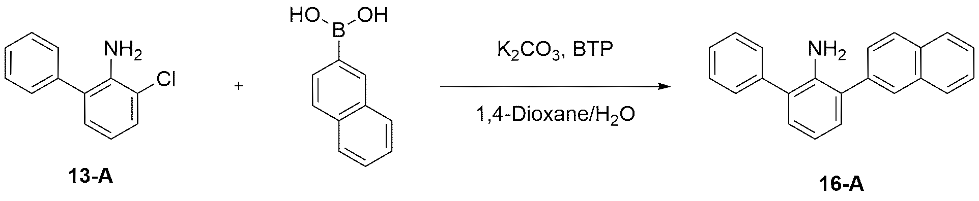
상기 합성예 13의 단계 1에서 수득한 화합물 13-A (40.0 g, 196.40 mmol)와 나프탈렌-2-일보론 산 (35.47 g, 206.22 mmol)을 이용하여 상기 합성예 13의 단계 2와 동일한 방법으로 상기 화합물 16-A (46.0 g, 79.29% 수율)를 수득하였다.Using the compound 13-A (40.0 g, 196.40 mmol) and naphthalene-2-ylboronic acid (35.47 g, 206.22 mmol) obtained in
단계 2) 화합물 16의 합성Step 2) Synthesis of Compound 16

상기 합성예 16의 단계 1에서 수득한 화합물 16-A (15.0 g, 50.78 mmol)와 4-브로모-1.1'-바이페닐 (24.27 g, 104.10 mmol)을 이용하여 상기 합성예 6과 동일한 방법으로 상기 화합물 16 (26.0 g, 85.37% 수율)을 수득하였다. (MS[M+H]+ = 600)Using the compound 16-A (15.0 g, 50.78 mmol) and 4-bromo-1.1'-biphenyl (24.27 g, 104.10 mmol) obtained in
합성예 17. 화합물 17의 합성Synthesis Example 17. Synthesis of Compound 17

상기 합성예 16의 단계 1에서 수득한 화합물 16-A (15.0 g, 50.78 mmol)와 2-브로모-9,9-디메틸-9H-플루오렌 (28.44 g, 104.10 mmol)을 이용하여 상기 합성예 6과 동일한 방법으로 상기 화합물 17 (26.2 g, 75.89% 수율)를 수득하였다. (MS[M+H]+ = 680)Synthesis using Compound 16-A (15.0 g, 50.78 mmol) obtained in
합성예 18. 화합물 18의 합성Synthesis Example 18. Synthesis of Compound 18
단계 1) 화합물 18-A의 합성Step 1) Synthesis of Compound 18-A

2-브로모-6-클로로아닐린 (50.0 g, 242.17 mmol)과 [1.1'-바이페닐]-4-일보론 산 (50.35 g, 254.27 mmol)을 이용하여 상기 합성예 13의 단계 1과 동일한 방법으로 상기 화합물 18-A (52.0 g, 76.75% 수율)를 수득하였다.The same method as in
단계 2) 화합물 18-B의 합성Step 2) Synthesis of Compound 18-B

상기 합성예 18의 단계 1에서 수득한 화합물 18-A (40.0 g, 142.97 mmol)와 나프탈렌-1-일보론 산 (25.82 g, 150.12 mmol)을 이용하여 상기 합성예 13의 단계 2와 동일한 방법으로 상기 화합물 18-B (40.0 g, 75.31% 수율)를 수득하였다.Using the compound 18-A (40.0 g, 142.97 mmol) and naphthalene-1-ylboronic acid (25.82 g, 150.12 mmol) obtained in
단계 3) 화합물 18의 합성Step 3) Synthesis of Compound 18

상기 합성예 18의 단계 2에서 수득한 화합물 18-B (15.0 g, 40.38 mmol)와 2-브로모-9,9-디메틸-9H-플루오렌 (22.61 g, 82.78 mmol)을 이용하여 상기 합성예 6과 동일한 방법으로 상기 화합물 18 (24.8 g, 81.24% 수율)을 수득하였다. (MS[M+H]+ = 756)Synthesis using Compound 18-B (15.0 g, 40.38 mmol) and 2-bromo-9,9-dimethyl-9 H -fluorene (22.61 g, 82.78 mmol) obtained in
합성예 19. 화합물 19의 합성Synthesis Example 19. Synthesis of Compound 19
단계 1) 화합물 19-A의 합성Step 1) Synthesis of Compound 19-A
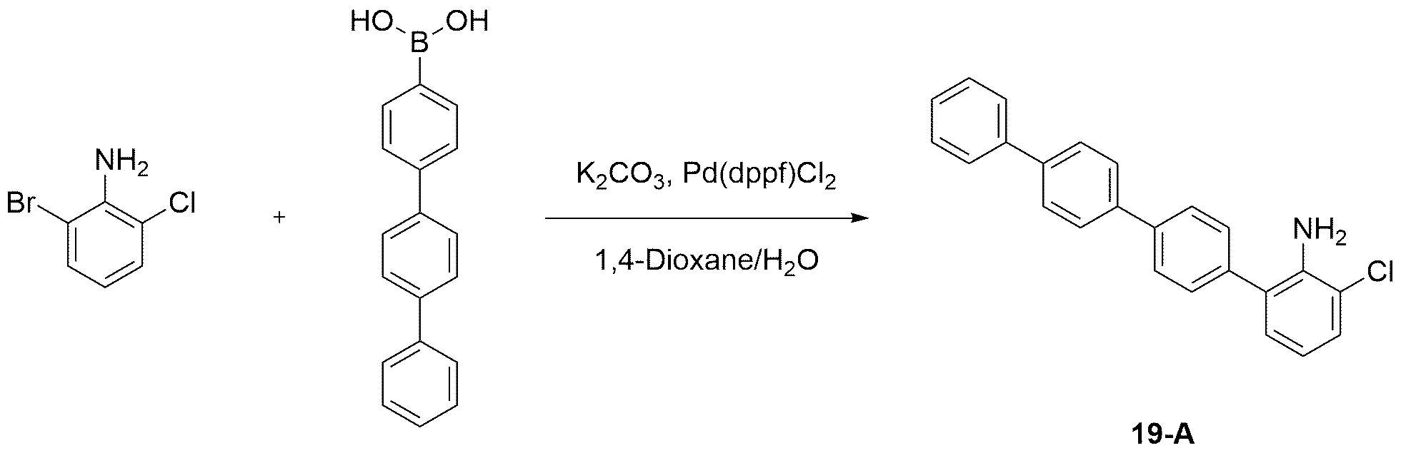
2-브로모-6-클로로아닐린 (50.0 g, 242.17 mmol)과 [1.1':4',1"-터페닐]-4-일보론산 (69.70 g, 254.27 mmol)을 이용하여 상기 합성예 13의 단계 1과 동일한 방법으로 상기 화합물 19-A (68.0 g, 78.90% 수율)를 수득하였다.2-Bromo-6-chloroaniline (50.0 g, 242.17 mmol) and [1.1 ': 4', 1 "-terphenyl] -4-ylboronic acid (69.70 g, 254.27 mmol) of Synthesis Example 13 Compound 19-A (68.0 g, 78.90% yield) was obtained in the same manner as in
단계 2) 화합물 19-B의 합성Step 2) Synthesis of Compound 19-B

상기 합성예 19의 단계 1에서 수득한 화합물 19-A (40.0 g, 112.40 mmol)와 [1,1'-바이페닐]-4-일보론 산 (23.37 g, 118.02 mmol)을 이용하여 상기 합성예 13의 단계 2와 동일한 방법으로 상기 화합물 19-B (40.0 g, 75.13% 수율)를 수득하였다.Synthesis Example using Compound 19-A (40.0 g, 112.40 mmol) obtained in
단계 3) 화합물 19의 합성Step 3) Synthesis of Compound 19

상기 합성예 19의 단계 2에서 수득한 화합물 19-B (15.0 g, 31.67 mmol)와 2-브로모-9,9-디메틸-9H-플루오렌 (15.13 g, 64.93 mmol)을 이용하여 상기 합성예 6과 동일한 방법으로 상기 화합물 19 (20.1 g, 81.58% 수율)를 수득하였다. (MS[M+H]+ = 778)Synthesis using Compound 19-B (15.0 g, 31.67 mmol) obtained in
합성예 20. 화합물 20의 합성Synthesis Example 20. Synthesis of Compound 20
단계 1) 화합물 20-A의 합성Step 1) Synthesis of Compound 20-A

상기 합성예 19의 단계 2에서 수득한 화합물 19-B (40.0 g, 84.46 mmol)와 4-브로모-1.1'-바이페닐 (19.69 g, 84.46 mmol)을 이용하여 상기 합성예 1의 단계 2와 동일한 방법으로 상기 화합물 20-A (42.0 g, 79.46% 수율)를 수득하였다.Using compound 19-B (40.0 g, 84.46 mmol) and 4-bromo-1.1'-biphenyl (19.69 g, 84.46 mmol) obtained in
단계 2) 화합물 20의 합성Step 2) Synthesis of Compound 20
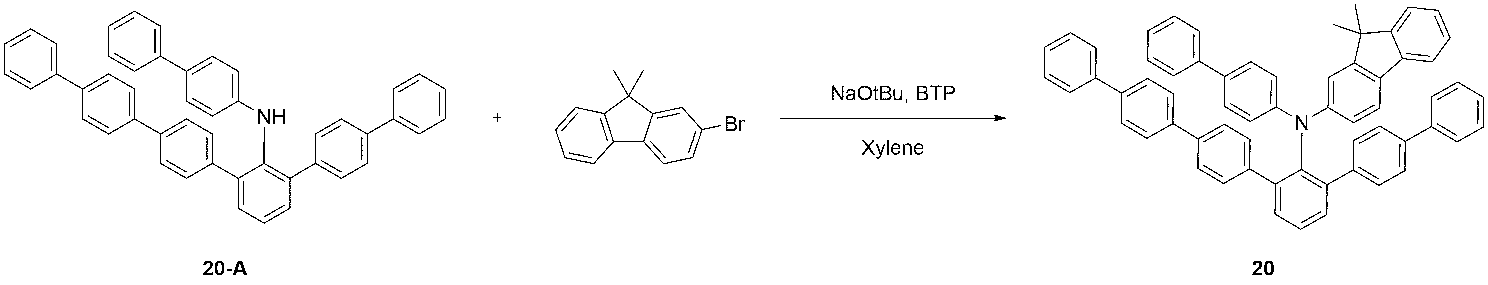
상기 합성예 20의 단계 1에서 수득한 화합물 20-A (20.0 g, 31.96 mmol)와 2-브로모-9,9-디메틸-9H-플루오렌 (8.90 g, 32.60 mmol)을 이용하여 상기 합성예 1의 단계 3과 동일한 방법으로 상기 화합물 20 (19.5 g, 74.58% 수율)을 수득하였다. (MS[M+H]+ = 818)The compound 20-A (20.0 g, 31.96 mmol) and 2-bromo-9,9-dimethyl -9 H obtained in the above Synthesis Example 20 1 - the use of fluorene (8.90 g, 32.60 mmol) synthesized The compound 20 (19.5 g, 74.58% yield) was obtained in the same manner as in
합성예 21. 화합물 21의 합성Synthesis Example 21. Synthesis of Compound 21
단계 1) 화합물 21-A의 합성Step 1) Synthesis of Compound 21-A
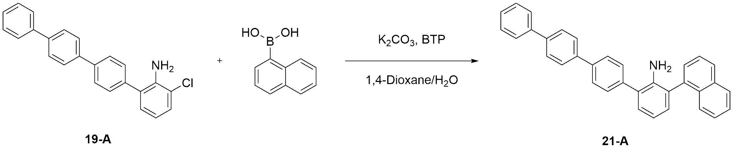
상기 합성예 19의 단계 1에서 수득한 화합물 19-A (40.0 g, 112.40 mmol)와 나프탈렌-1-일보론 산 (20.30 g, 118.02 mmol)을 이용하여 상기 합성예 13의 단계 2와 동일한 방법으로 상기 화합물 21-A (40.0 g, 79.51% 수율)를 수득하였다.Using the compound 19-A (40.0 g, 112.40 mmol) obtained in
단계 2) 화합물 21의 합성Step 2) Synthesis of Compound 21
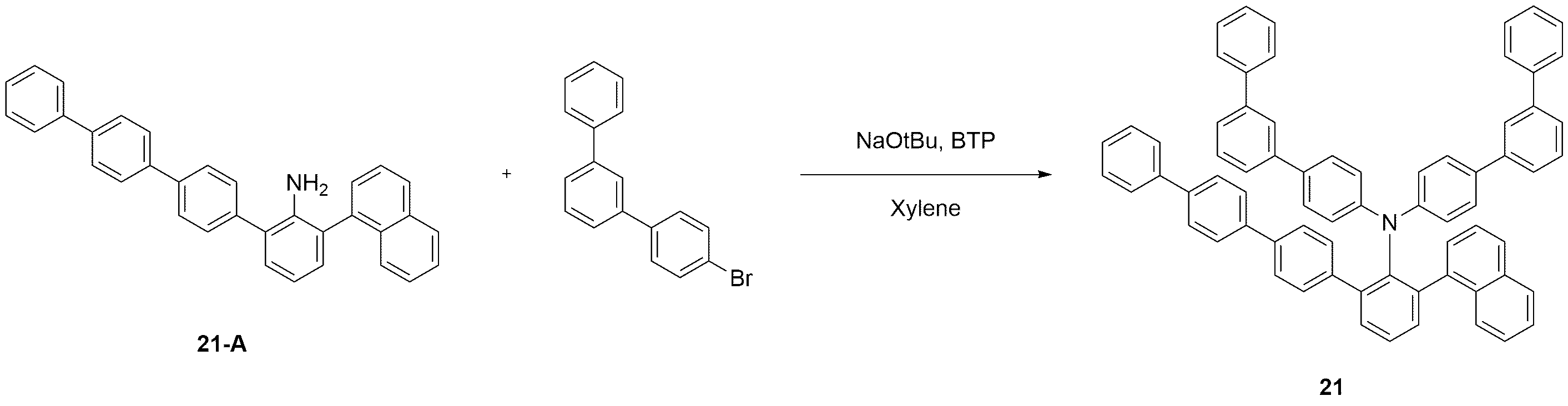
상기 합성예 21의 단계 1에서 수득한 화합물 21-A (15.0 g, 33.51 mmol)와 4-브로모-1,1':3',1"-터페닐 (21.24 g, 68.70 mmol)을 이용하여 상기 합성예 6과 동일한 방법으로 상기 화합물 21 (24.0 g, 79.21% 수율)을 수득하였다. (MS[M+H]+ = 904)Using Compound 21-A (15.0 g, 33.51 mmol) obtained in
합성예 22. 화합물 22의 합성Synthesis Example 22. Synthesis of Compound 22
단계 1) 화합물 22-A의 합성Step 1) Synthesis of Compound 22-A

상기 합성예 21의 단계 1에서 수득한 화합물 21-A (40.0 g, 89.37 mmol)와 4-브로모-1.1'-바이페닐 (20.83 g, 89.37 mmol)을 이용하여 상기 합성예 1의 단계 2와 동일한 방법으로 상기 화합물 22-A (43.0 g, 80.22% 수율)를 수득하였다.Using compound 21-A (40.0 g, 89.37 mmol) and 4-bromo-1.1'-biphenyl (20.83 g, 89.37 mmol) obtained in
단계 2) 화합물 22의 합성Step 2) Synthesis of Compound 22
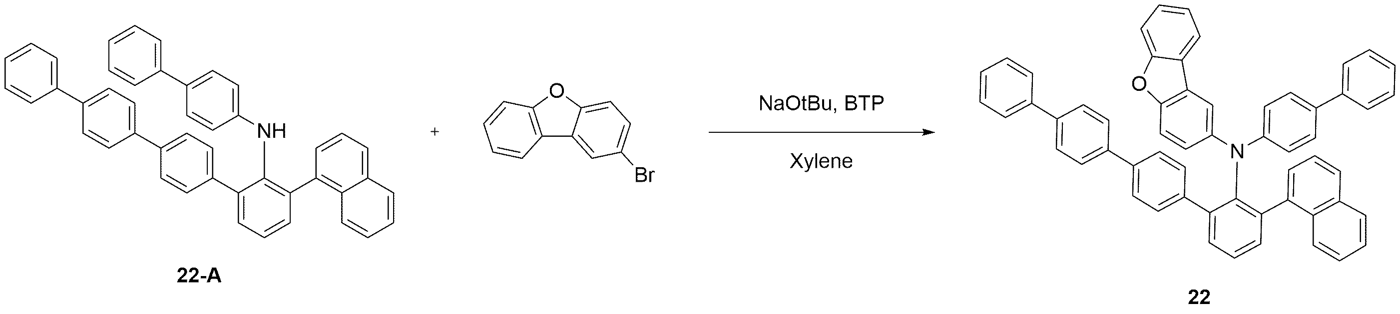
상기 합성예 22의 단계 1에서 수득한 화합물 22-A (20.0 g, 33.35 mmol)와 2-브로모디벤조[b,d]퓨란 (8.40 g, 34.01 mmol)을 이용하여 상기 합성예 1의 단계 3과 동일한 방법으로 상기 화합물 22 (20.0 g, 75.72% 수율)를 수득하였다. (MS[M+H]+ = 792)
합성예 23. 화합물 23의 합성Synthesis Example 23. Synthesis of Compound 23
단계 1) 화합물 23-A의 합성Step 1) Synthesis of Compound 23-A
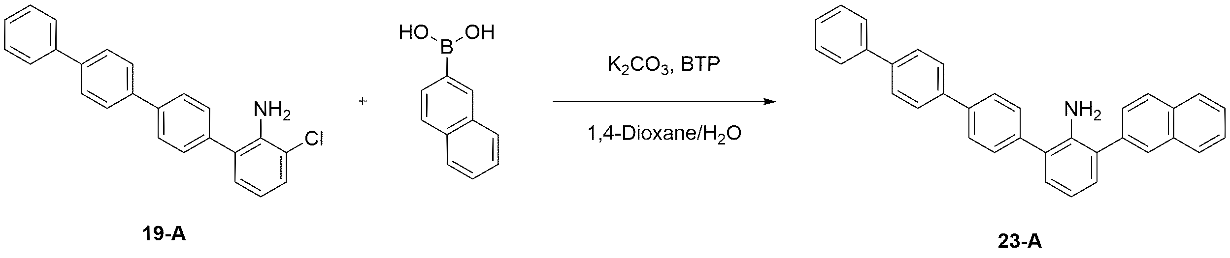
상기 합성예 19의 단계 1에서 수득한 화합물 19-A (40.0 g, 112.40 mmol)와 나프탈렌-2-일보론 산 (20.30 g, 118.02 mmol)을 이용하여 상기 합성예 13의 단계 2와 동일한 방법으로 상기 화합물 23-A (42.0 g, 83.49% 수율)를 수득하였다.Using the compound 19-A (40.0 g, 112.40 mmol) obtained in
단계 2) 화합물 23의 합성Step 2) Synthesis of Compound 23

상기 합성예 23의 단계 1에서 수득한 화합물 23-A (15.0 g, 33.51 mmol)와 3-브로모-1,1'-바이페닐 (16.02 g, 68.70 mmol)을 이용하여 상기 합성예 6과 동일한 방법으로 상기 화합물 23 (21.0 g, 83.34% 수율)을 수득하였다. (MS[M+H]+ = 752)Same as in Synthesis Example 6 using Compound 23-A (15.0 g, 33.51 mmol) and 3-bromo-1,1'-biphenyl (16.02 g, 68.70 mmol) obtained in
합성예 24. 화합물 24의 합성Synthesis Example 24. Synthesis of Compound 24

상기 합성예 23의 단계 1에서 수득한 화합물 23-A (15.0 g, 33.51 mmol)와 2-브로모디벤조[b,d]퓨란 (16.98 g, 68.70 mmol)을 이용하여 상기 합성예 6과 동일한 방법으로 상기 화합물 24 (21.0 g, 80.35% 수율)를 수득하였다. (MS[M+H]+ = 780)The same method as in Synthesis Example 6 using Compound 23-A (15.0 g, 33.51 mmol) and 2-bromodibenzo [ b, d ] furan (16.98 g, 68.70 mmol) obtained in
<실험예 및 비교실험예><Experimental Example and Comparative Experimental Example>
실험예 1-1Experimental Example 1-1
ITO(Indium Tin Oxide)가 1400 옹스트롬(Å, angstrom)의 두께로 박막 코팅된 유리 기판을 세제를 녹인 증류수에 넣고 초음파로 세척하였다. 이때, 세제로는 피셔사(Fischer Co.) 제품을 사용하였으며, 증류수로는 밀러포어사(Millipore Co.) 제품의 필터(Filter)로 2차로 걸러진 증류수를 사용하였다. ITO를 30분간 세척한 후 증류수로 2회 반복하여 초음파 세척을 10 분간 진행하였다. 증류수 세척이 끝난 후, 이소프로필알콜, 아세톤, 메탄올의 용제로 초음파 세척을 하고 건조시킨 후 플라즈마 세정기로 수송시켰다. 또한, 산소 플라즈마를 이용하여 상기 기판을 5 분간 세정한 후 진공 증착기로 기판을 수송시켰다.ITO (Indium Tin Oxide) 1400 Angstrom (Å, angstrom), the thickness of the glass-coated glass substrate was placed in distilled water with detergent and washed with ultrasonic waves. At this time, Fischer (Fischer Co.) was used as the detergent, and distilled water filtered secondarily by a filter of Millipore Co. was used as the distilled water. After washing the ITO for 30 minutes, ultrasonic washing was repeated for 2 minutes with distilled water for 10 minutes. After washing with distilled water, ultrasonic cleaning was performed with a solvent of isopropyl alcohol, acetone, and methanol, followed by drying and transporting to a plasma cleaner. In addition, the substrate was washed for 5 minutes using oxygen plasma, and then transferred to a vacuum evaporator.
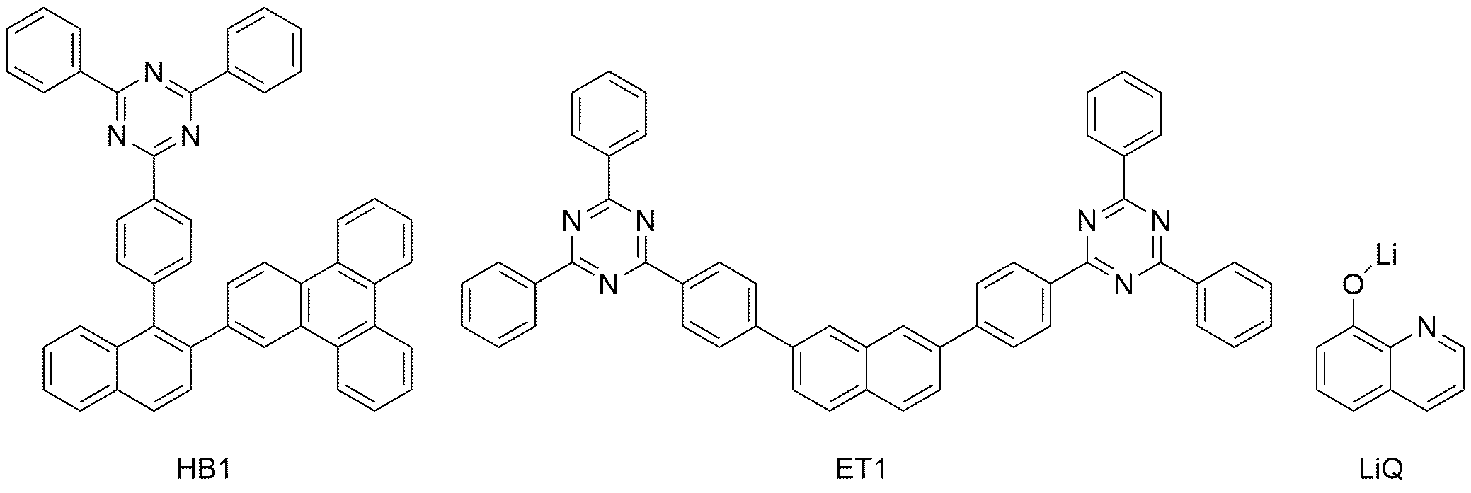
이렇게 준비된 ITO 투명 전극 위에 하기 화학식 HAT로 표시되는 화합물을 100 Å의 두께로 열 진공 증착하여 정공주입층을 형성하였다. 그 위에 정공수송층으로 하기 화학식 HT1로 표시되는 화합물을 1150 Å 두께로 진공 증착한 후, 전자억제층으로 상기 합성예 1에서 제조된 화합물 1을 150 Å의 두께로 열 진공 증착하였다. 이어서, 발광층으로 하기 화학식 BH로 표시되는 화합물 및 하기 화학식 BD로 표시되는 화합물을 25:1의 중량비로 200 Å의 두께로 진공 증착하였다. 이어서, 정공억제층으로 하기 화학식 HB1으로 표시되는 화합물을 50 Å의 두께로 진공 증착하였다. 이어서, 전자수송 및 전자주입을 동시에 하는 층으로 하기 화학식 ET1로 표시되는 화합물과 하기 LiQ로 표시되는 화합물을 1:1의 중량비로 310 Å의 두께로 열 진공 증착하였다. 상기 전자 수송 및 전자 주입층 위에 순차적으로 12 Å의 두께로 리튬플로라이드(LiF)와 1000 Å 두께로 알루미늄을 증착하여 음극을 형성하여, 유기 발광 소자를 제조하였다.On the ITO transparent electrode thus prepared, a compound represented by the following chemical formula HAT was thermally vacuum-deposited to a thickness of 100 을 to form a hole injection layer. Then, a compound represented by the following Chemical Formula HT1 was vacuum-deposited to a thickness of 1150 정 as a hole transport layer, and then the


실험예 1-2 내지 1-15 및 비교실험예 1-1 내지 1-8Experimental Examples 1-2 to 1-15 and Comparative Experimental Examples 1-1 to 1-8
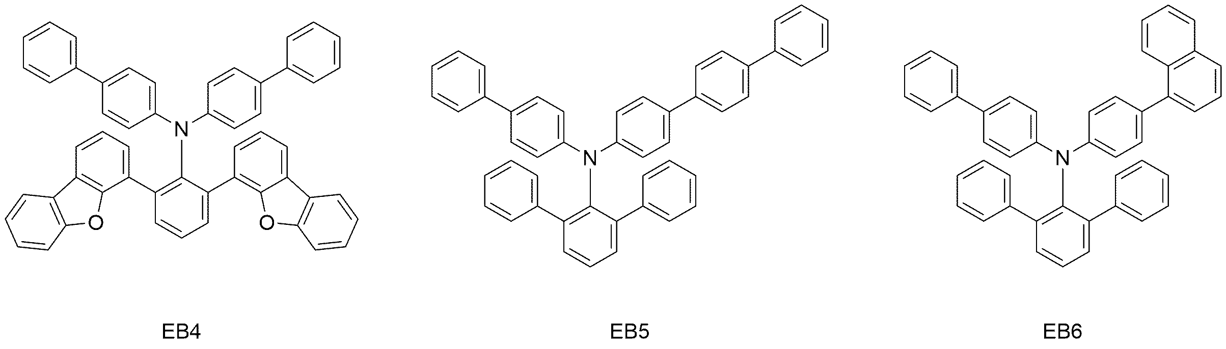
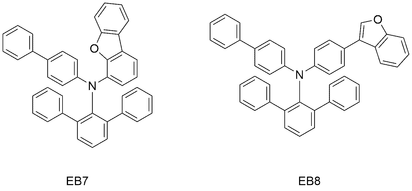
상기 실험예 1-1에서 화합물 1 대신 하기 표 1에 기재된 화합물을 사용하는 것을 제외하고는, 상기 실험예 1-1과 동일한 방법으로 실험예 1-2 내지 1-15 및 비교실험예 1-1 내지 1-8의 유기 발광 소자를 제작하였다. 실험예 및 비교실험예에서 제조한 유기 발광 소자에 10 mA/cm2의 전류를 인가하였을 때, 전압, 효율, 색좌표 및 수명을 측정하고 그 결과를 하기 표 1에 나타내었다. 한편, T95는 휘도가 초기 휘도(6000 nit)에서 95%로 감소되는 데 소요되는 시간을 의미한다. Experimental Examples 1-2 to 1-15 and Comparative Experimental Example 1-1 were used in the same manner as in Experimental Example 1-1, except that the compound shown in Table 1 below was used instead of
하기 표 1에서 전자억제층에 사용된 화합물 EB1 내지 EB8은, 각각 하기 화학식 EB1 내지 EB8로 표시되는 것이다. In Table 1, the compounds EB1 to EB8 used in the electron suppressing layer are represented by the following formulas EB1 to EB8, respectively.

(x, y)Color coordinate
(x, y)
(T95, hr)life span
(T95, hr)
상기 표 1에 나타난 바와 같이, 본 발명의 화합물은 전자 억제 능력이 우수하여 이를 전자억제층으로 사용한 유기 발광 소자는 구동 전압, 효율, 수명 면에서 현저한 효과를 나타내는 것으로 확인되었다. As shown in Table 1, it was confirmed that the compound of the present invention has excellent electron suppression ability, and the organic light emitting device using it as an electron suppressing layer exhibits remarkable effects in terms of driving voltage, efficiency, and life.
실험예 2-1 내지 2-15 및 비교실험예 1-1, 2-1 내지 2-7Experimental Examples 2-1 to 2-15 and Comparative Experimental Examples 1-1, 2-1 to 2-7
상기 실험예 1-1에서 전자억제층으로 화합물 1 대신 상기 화학식 EB1으로 표시되는 화합물을 사용하고, 정공수송층으로 하기 화학식 HT1으로 표시되는 화합물 대신 하기 표 2에 기재된 화합물을 사용하는 것을 제외하고는, 상기 실험예 1-1과 동일한 방법으로 실험예 2-1 내지 2-15 및 비교실험예 2-1 내지 2-7의 유기 발광 소자를 제작하였다. 실험예 및 비교실험예에서 제조한 유기 발광 소자에 10 mA/cm2의 전류를 인가하였을 때, 전압, 효율, 색좌표 및 수명을 측정하고 그 결과를 하기 표 1에 나타내었다. 한편, T95는 휘도가 초기 휘도(6000 nit)에서 95%로 감소되는 데 소요되는 시간을 의미한다.Except for using the compound represented by Formula EB1 instead of
하기 표 2에서 정공수송층에 사용된 화합물 HT1 내지 HT8은, 각각 하기 화학식 HT1 내지 HT8로 표시되는 것이다. In Table 2, the compounds HT1 to HT8 used in the hole transport layer are represented by the following formulas HT1 to HT8, respectively.


(x, y)Color coordinate
(x, y)
(T95, hr)life span
(T95, hr)
상기 표 2에 나타난 바와 같이, 본 발명의 화합물은 정공 수송 능력이 우수하여 이를 정공수송층으로 사용한 유기 발광 소자는 구동 전압, 효율, 수명 면에서 현저한 효과를 나타내는 것으로 확인되었다.As shown in Table 2, it was confirmed that the compound of the present invention has excellent hole transporting ability, and thus the organic light emitting device using it as a hole transport layer exhibits remarkable effects in terms of driving voltage, efficiency, and life.
1: 기판
2: 양극
3: 발광층
4: 음극
5: 정공수송층
6: 전자억제층
7: 전자수송층
8: 정공주입층
9: 정공억제층1: substrate 2: anode
3: light emitting layer 4: cathode
5: hole transport layer 6: electron suppressing layer
7: electron transport layer 8: hole injection layer
9: Hole suppression layer
Claims (9)
[화학식 1]

상기 화학식 1에서,
Ar1은 및 Ar2는 각각 독립적으로 C6-60 아릴; 또는 N, O 및 S로 구성되는 군으로부터 선택되는 어느 하나 이상의 헤테로원자를 포함하는 치환 또는 비치환된 C5-60 헤테로아릴이고,
Ar3 및 Ar4는 각각 독립적으로 C6-60 아릴이고, 단, Ar3 및 Ar4가 중 적어도 하나가 비페닐릴 또는 나프틸이다.
Compound represented by the formula (1):
[Formula 1]
In Chemical Formula 1,
Ar 1 and Ar 2 are each independently C 6-60 aryl; Or a substituted or unsubstituted C 5-60 heteroaryl containing any one or more heteroatoms selected from the group consisting of N, O and S,
Ar 3 and Ar 4 are each independently C 6-60 aryl, provided that at least one of Ar 3 and Ar 4 is biphenylyl or naphthyl.
Ar1 및 Ar2는 각각 독립적으로, C6-30 아릴; 또는 N, O 및 S로 구성되는 군으로부터 선택되는 어느 하나 이상의 헤테로원자를 포함하는 치환 또는 비치환된 C5-30 헤테로아릴인,
화합물.
According to claim 1,
Ar 1 and Ar 2 are each independently C 6-30 aryl; Or a substituted or unsubstituted C 5-30 heteroaryl containing any one or more heteroatoms selected from the group consisting of N, O and S,
compound.
Ar1 및 Ar2는 각각 독립적으로, 페닐, 비페닐릴, 터페닐릴, 쿼터페닐릴, 나프틸, 페난트레닐, 트리페닐레닐, 디메틸플루오레닐, 디페닐플루오레닐, 디벤조퓨라닐, 디벤조티오페닐, 9-페닐-9H-카바졸릴, 나프틸로 치환된 페닐, 페난트레닐로 치환된 페닐, 또는 트리페닐레닐로 치환된 페닐인,
화합물.
According to claim 1,
Ar 1 and Ar 2 are each independently phenyl, biphenylyl, terphenylyl, quarterphenylyl, naphthyl, phenanthrenyl, triphenylenyl, dimethylfluorenyl, diphenylfluorenyl, dibenzofuranyl , Dibenzothiophenyl, 9-phenyl-9H-carbazolyl, phenyl substituted with naphthyl, phenyl substituted with phenanthrenyl, or phenyl substituted with triphenylenyl,
compound.
Ar3 및 Ar4는 각각 독립적으로, C6-30 아릴인,
화합물.
According to claim 1,
Ar 3 and Ar 4 are each independently C 6-30 aryl,
compound.
Ar3 및 Ar4는 각각 독립적으로, 페닐, 비페닐릴, 터페닐릴, 또는 나프틸인,
화합물.
According to claim 1,
Ar 3 and Ar 4 are each independently phenyl, biphenylyl, terphenylyl, or naphthyl,
compound.
상기 화학식 1로 표시되는 화합물은, 하기 화학식 1-1 내지 1-12 중 어느 하나로 표시되는 것인,
화합물:
[화학식 1-1]

[화학식 1-2]
[화학식 1-3]

[화학식 1-4]

[화학식 1-5]

[화학식 1-6]

[화학식 1-7]
[화학식 1-8]

[화학식 1-9]
[화학식 1-10]
[화학식 1-11]

[화학식 1-12]

상기 화학식 1-1 내지 1-12에서,
Ar1 및 Ar-2은 제1항에 정의한 바와 같으며,
R1, R2, R3, R4, 및 R5는 각각 독립적으로, 수소, 중수소, 할로겐기, 니트릴기, 실릴기, C6-60 아릴, C6-60 아르알킬, C6-60 아르알케닐; 또는 N, O 및 S로 구성되는 군으로부터 선택되는 어느 하나 이상의 헤테로원자를 포함하는 치환 또는 비치환된 C5-60 헤테로아릴이다.
According to claim 1,
The compound represented by Formula 1, is represented by any one of the following Formulas 1-1 to 1-12,
compound:
[Formula 1-1]
[Formula 1-2]
[Formula 1-3]
[Formula 1-4]
[Formula 1-5]
[Formula 1-6]
[Formula 1-7]
[Formula 1-8]
[Formula 1-9]
[Formula 1-10]
[Formula 1-11]
[Formula 1-12]
In Chemical Formulas 1-1 to 1-12,
Ar 1 and Ar -2 are as defined in claim 1,
R 1 , R 2 , R 3 , R 4 , and R 5 are each independently hydrogen, deuterium, halogen group, nitrile group, silyl group, C 6-60 aryl, C 6-60 aralkyl, C 6-60 Aralkenyl; Or a substituted or unsubstituted C 5-60 heteroaryl containing any one or more heteroatoms selected from the group consisting of N, O and S.
R1, R2, R3, R4, 및 R5는 수소인,
화합물.
According to claim 4,
R 1 , R 2 , R 3 , R 4 , and R 5 are hydrogen,
compound.
상기 화학식 1로 표시되는 화합물은 하기로 구성되는 군으로부터 선택되는 어느 하나인,
화합물:
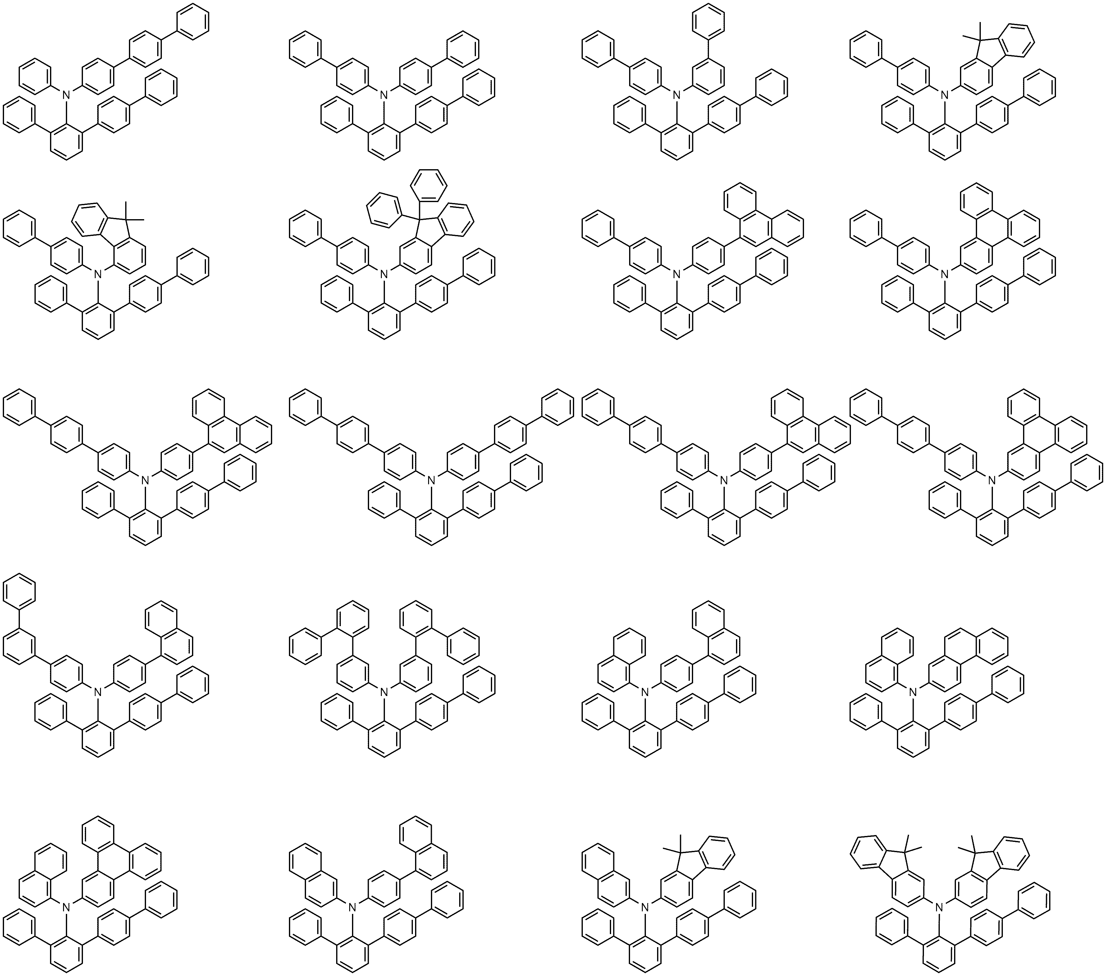

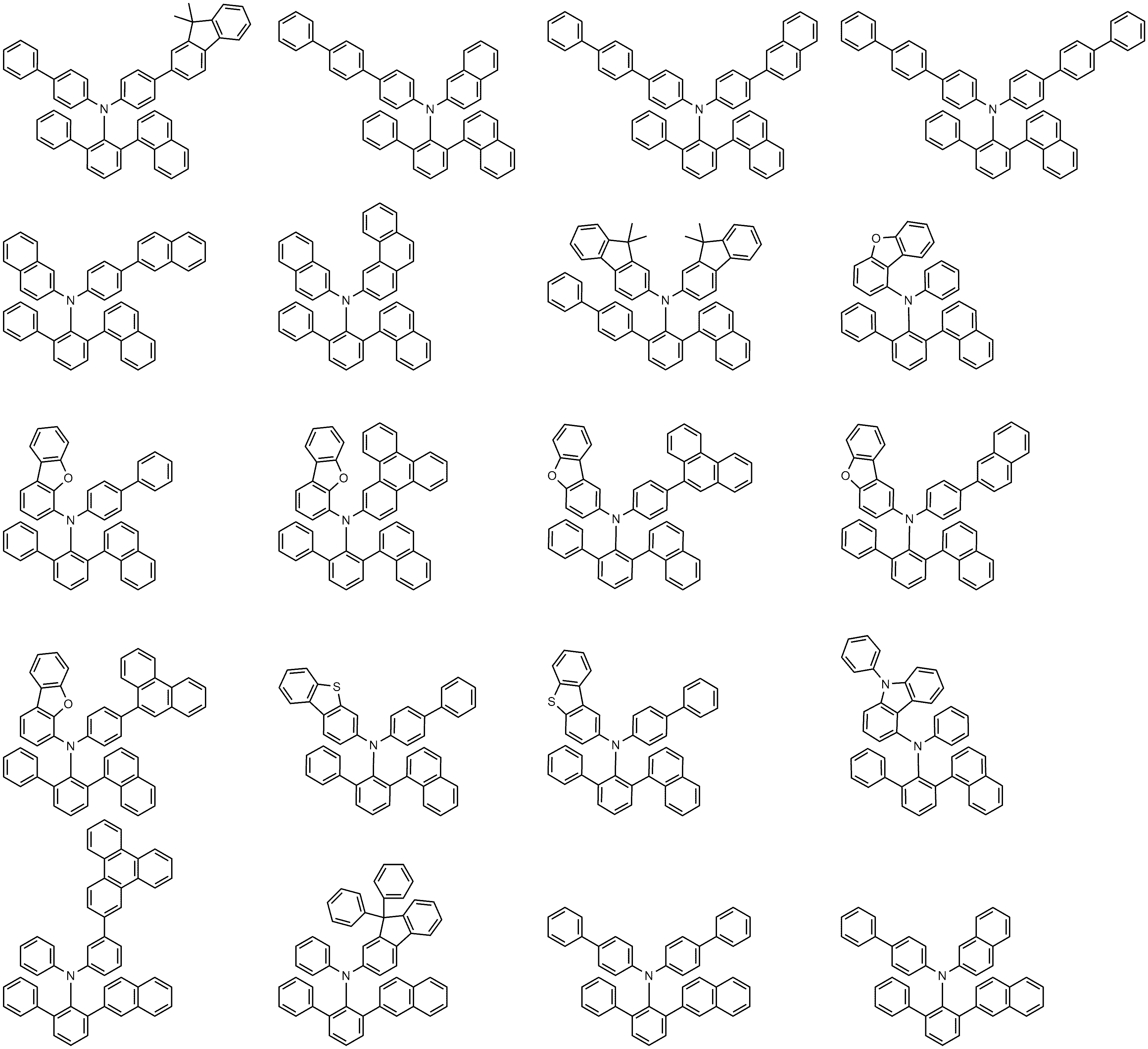


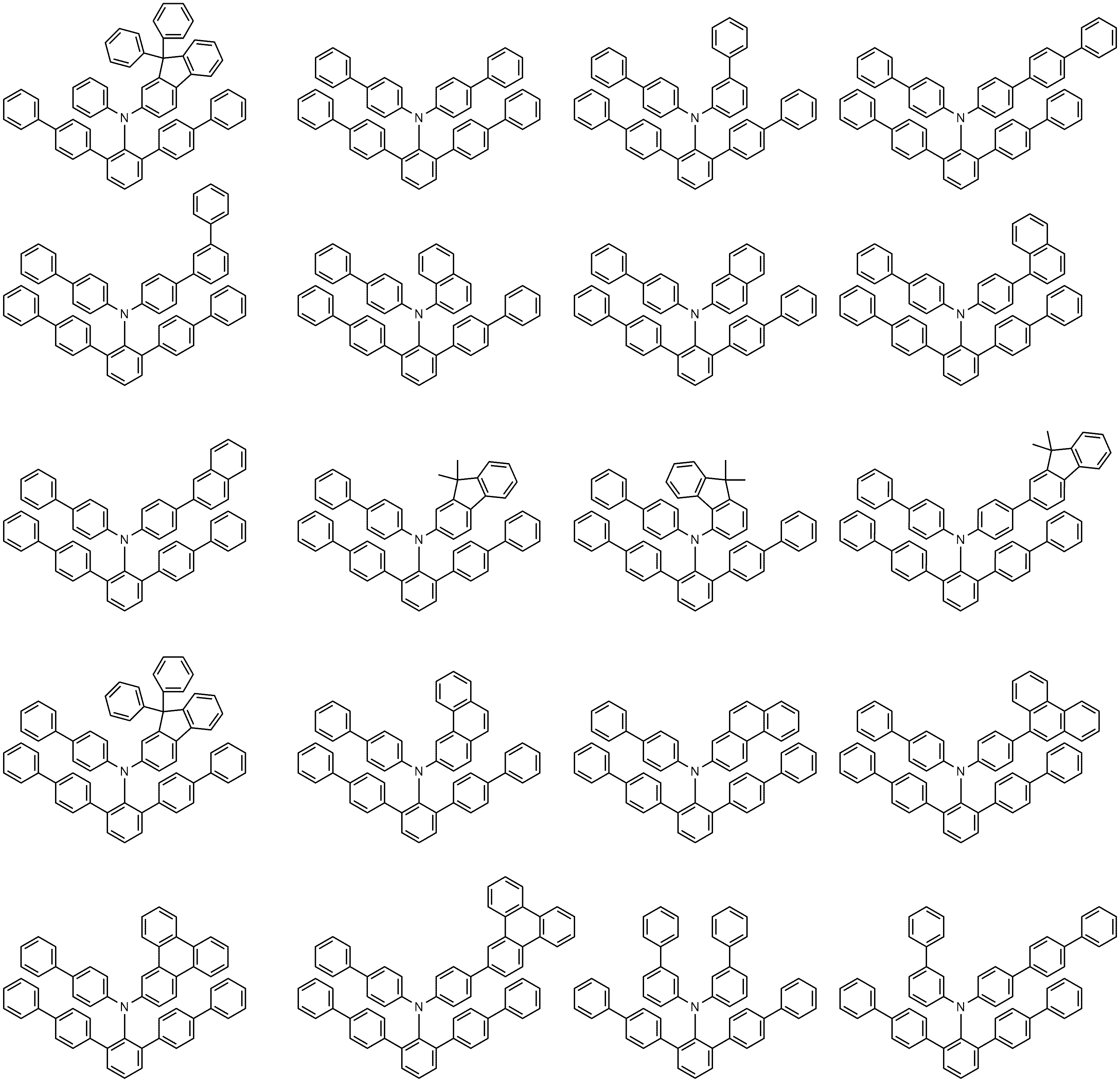
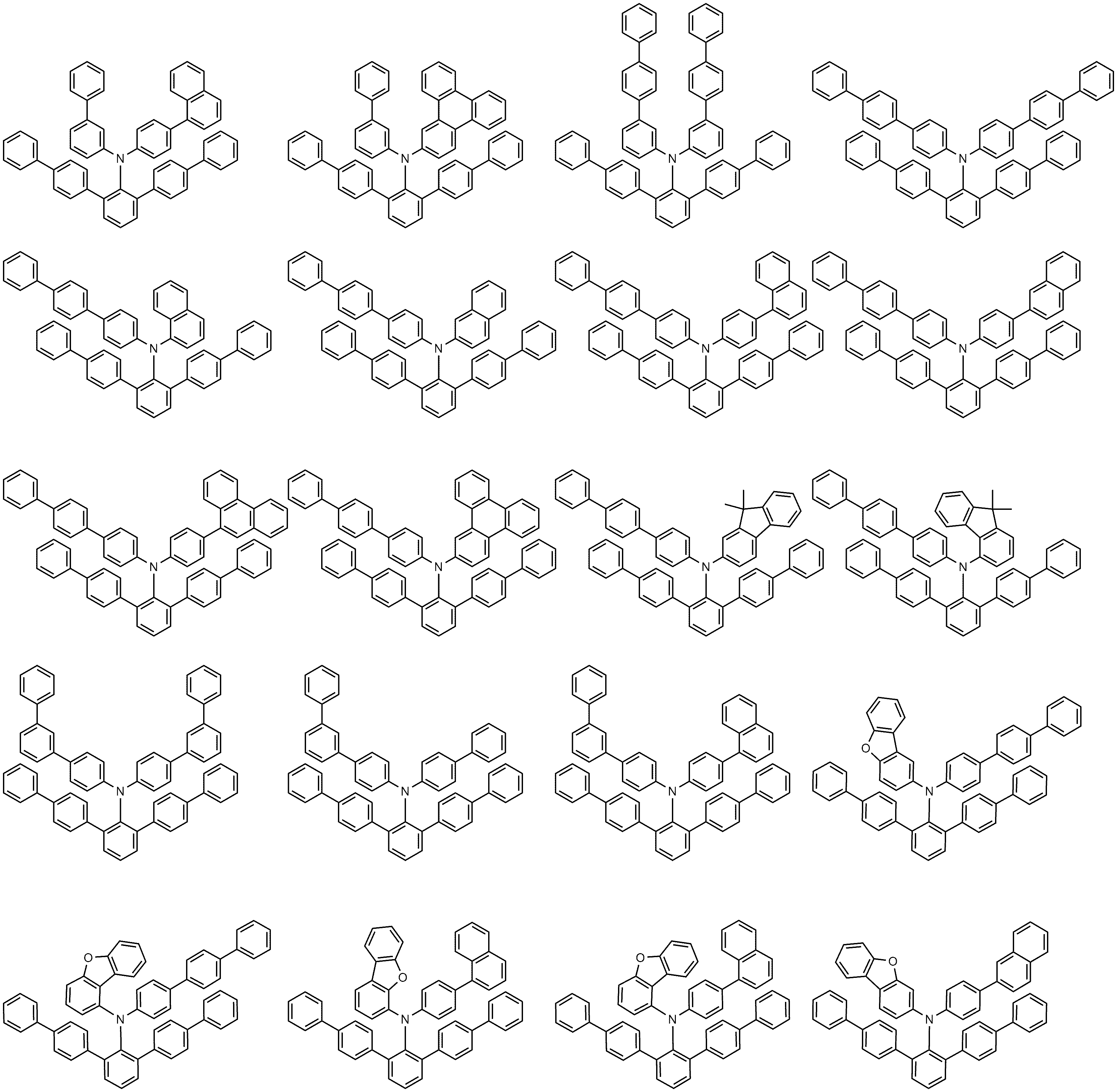


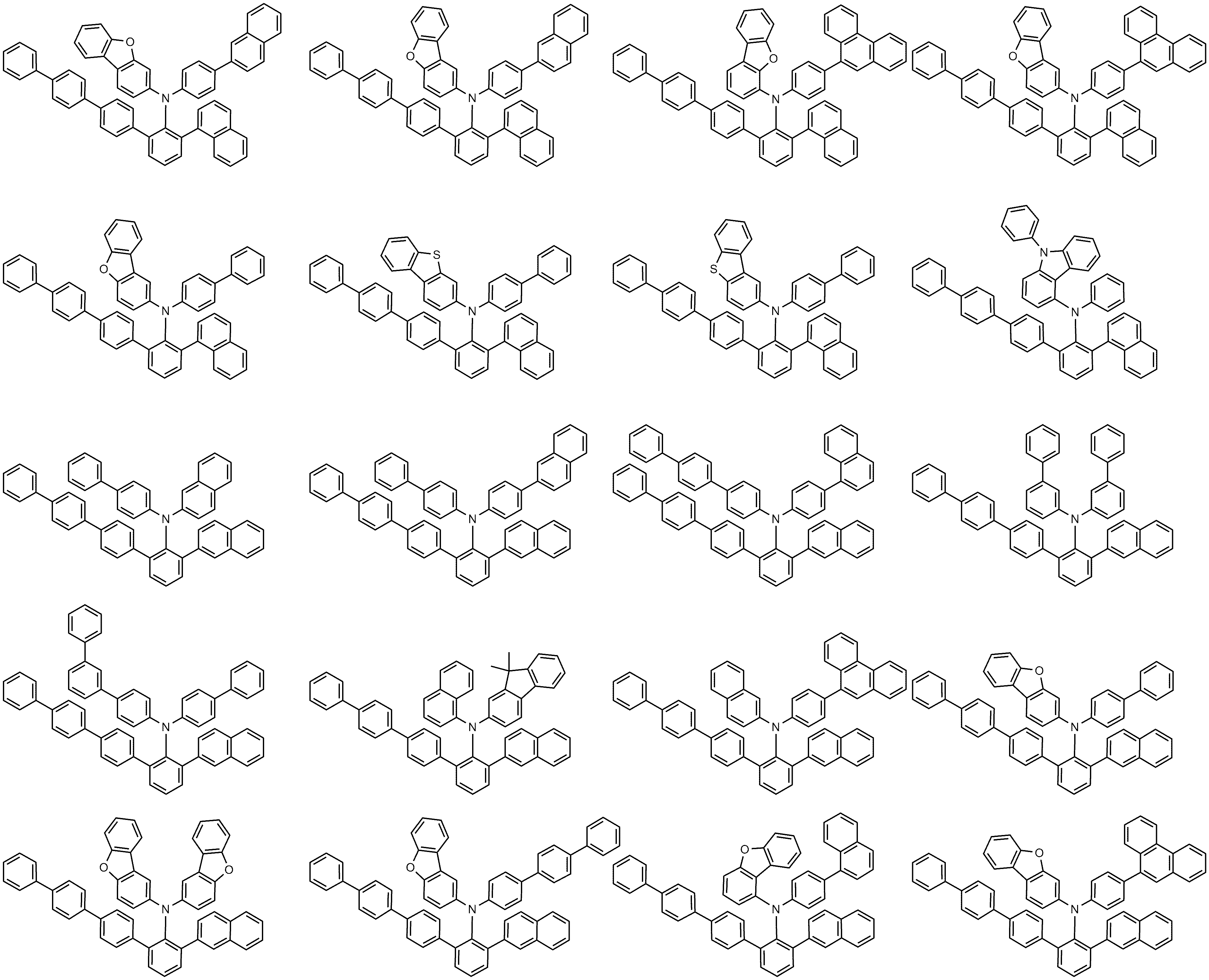
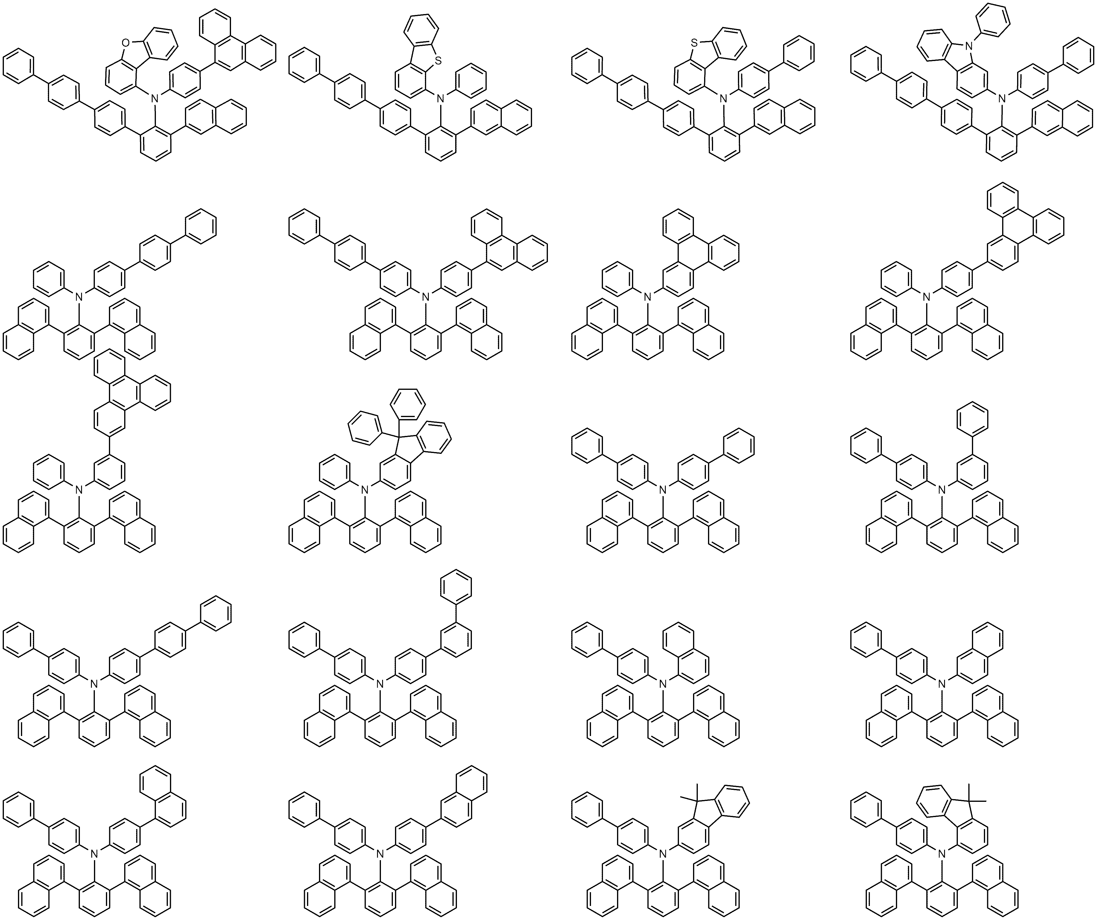


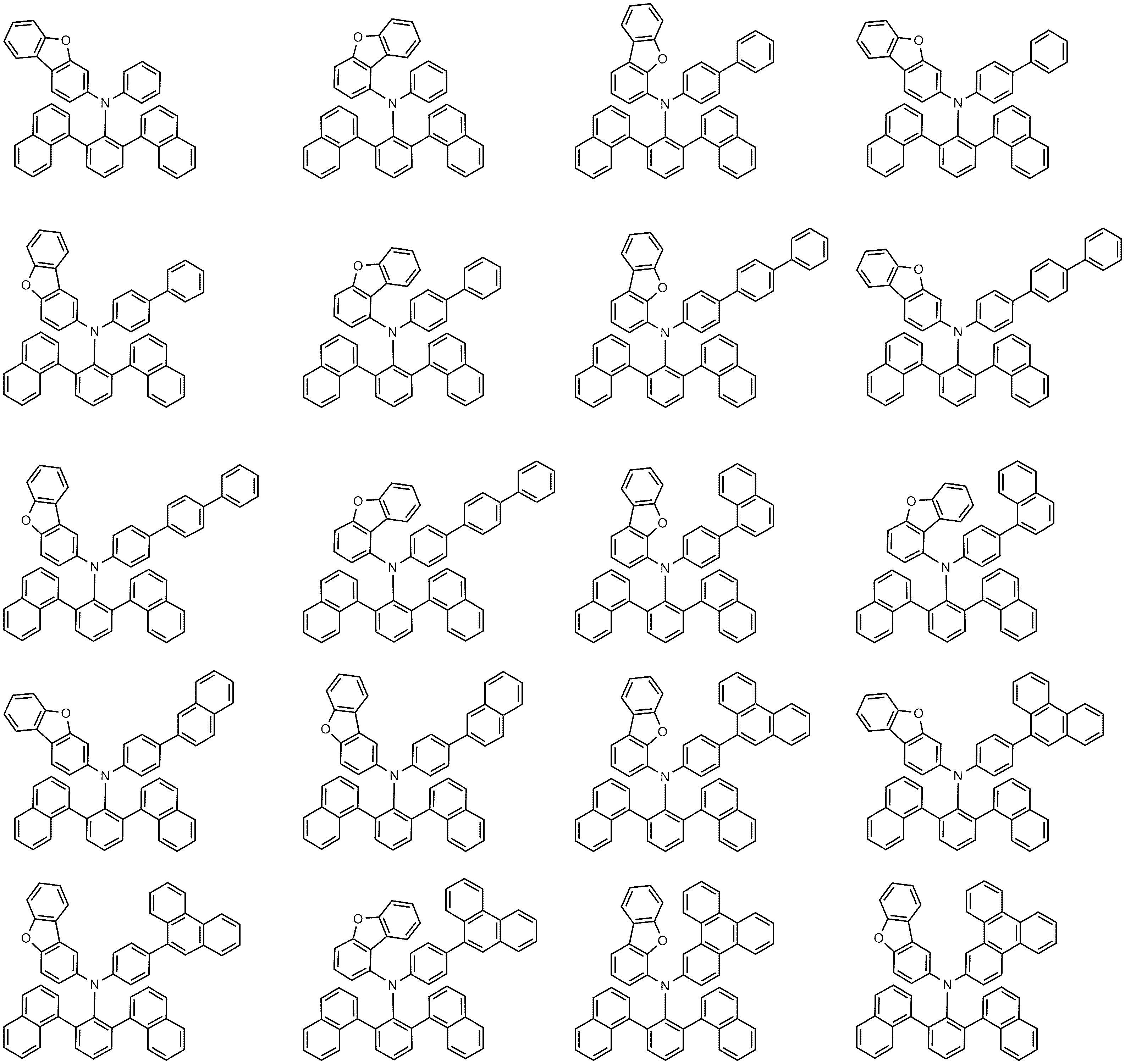

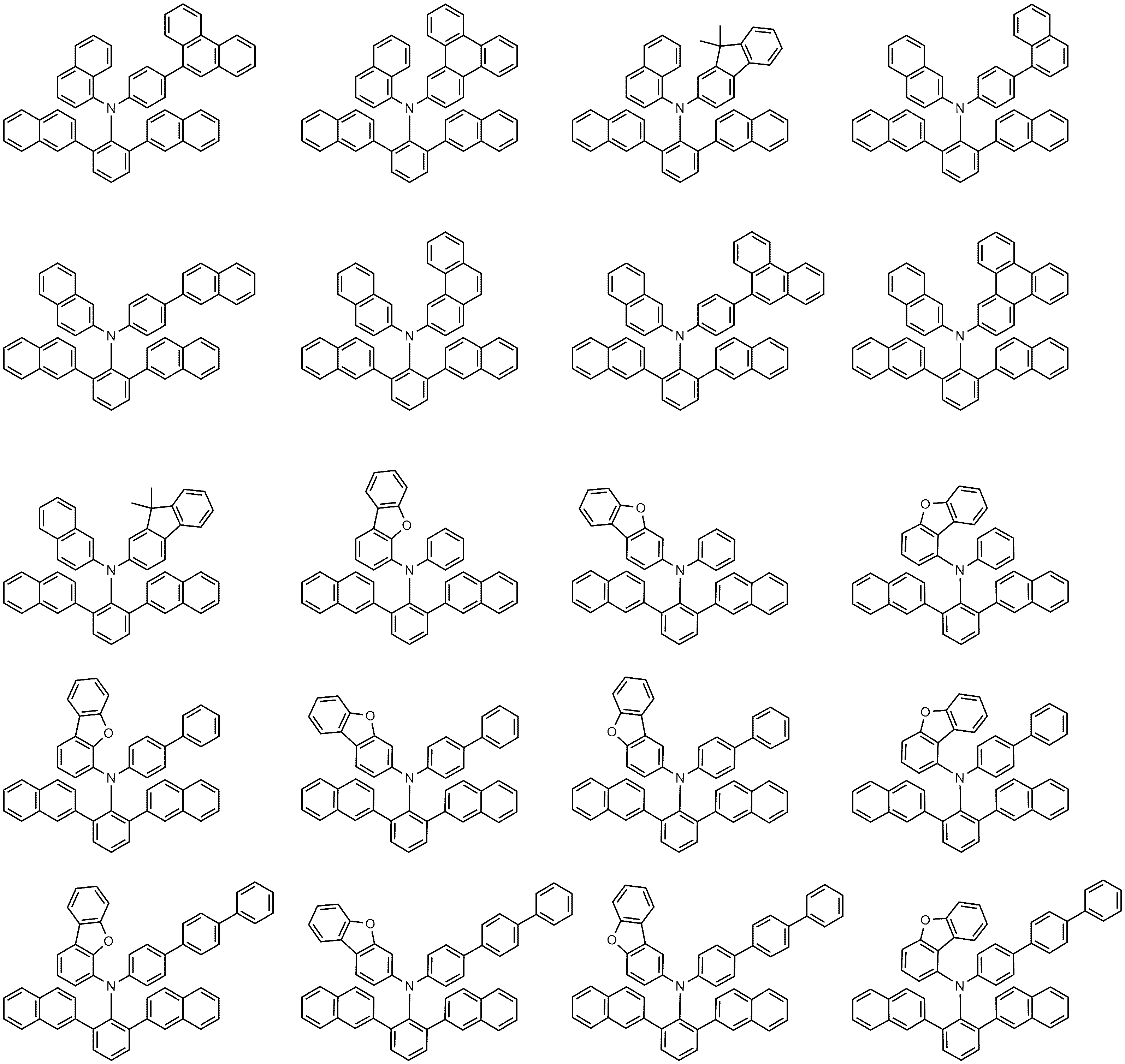
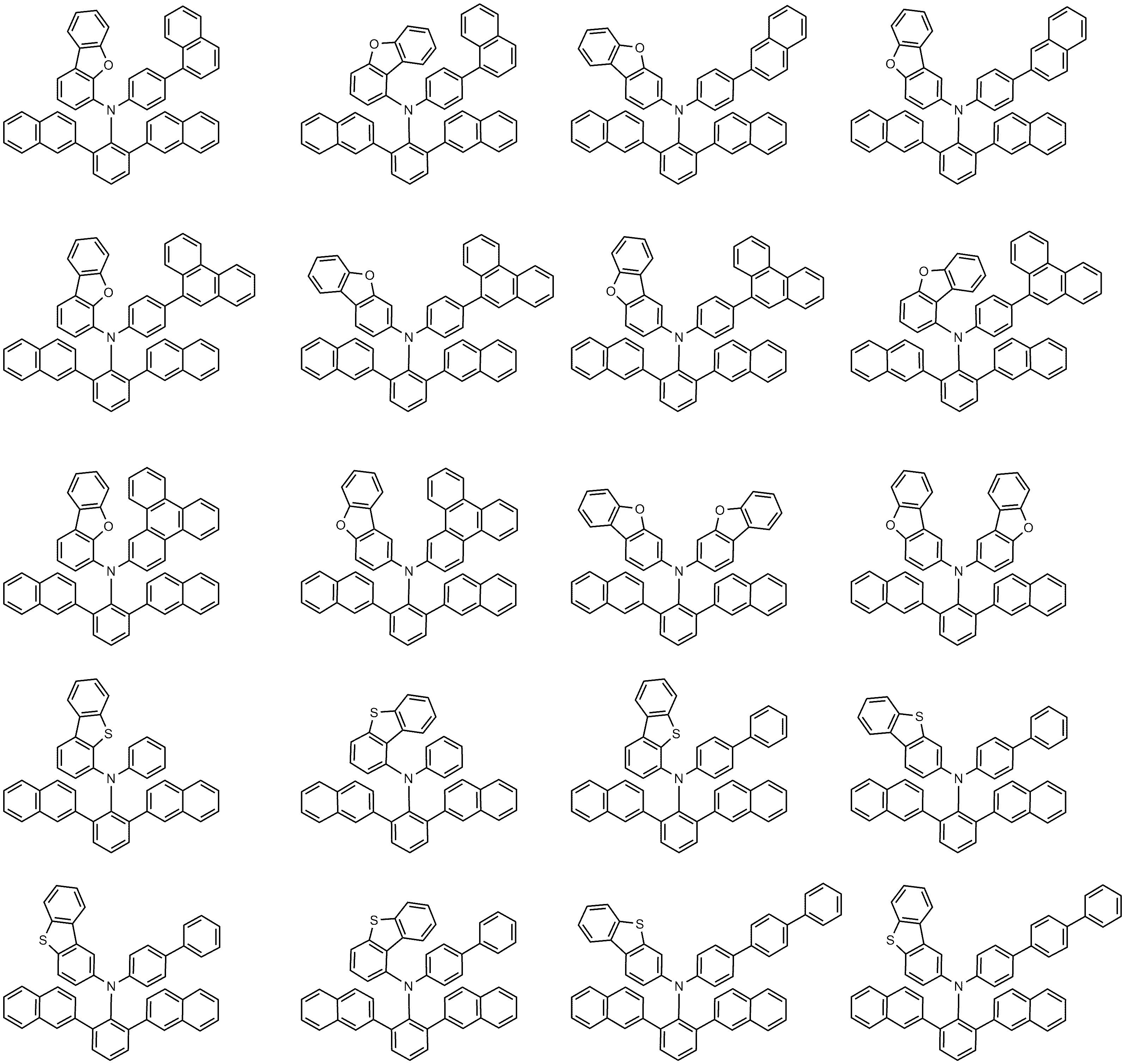

According to claim 1,
The compound represented by Formula 1 is any one selected from the group consisting of,
compound:
Priority Applications (2)
| Application Number | Priority Date | Filing Date | Title |
|---|---|---|---|
| PCT/KR2019/013519 WO2020080799A1 (en) | 2018-10-15 | 2019-10-15 | Novel compound and organic light emitting diode comprising same |
| CN201980055108.1A CN112601732B (en) | 2018-10-15 | 2019-10-15 | Novel compound and organic light emitting device comprising the same |
Applications Claiming Priority (2)
| Application Number | Priority Date | Filing Date | Title |
|---|---|---|---|
| KR20180122688 | 2018-10-15 | ||
| KR1020180122688 | 2018-10-15 |
Publications (2)
| Publication Number | Publication Date |
|---|---|
| KR20200042428A true KR20200042428A (en) | 2020-04-23 |
| KR102266981B1 KR102266981B1 (en) | 2021-06-18 |
Family
ID=70472683
Family Applications (1)
| Application Number | Title | Priority Date | Filing Date |
|---|---|---|---|
| KR1020190127309A KR102266981B1 (en) | 2018-10-15 | 2019-10-14 | Novel compound and organic light emitting device comprising the same |
Country Status (2)
| Country | Link |
|---|---|
| KR (1) | KR102266981B1 (en) |
| CN (1) | CN112601732B (en) |
Families Citing this family (3)
| Publication number | Priority date | Publication date | Assignee | Title |
|---|---|---|---|---|
| KR20200122116A (en) | 2019-04-17 | 2020-10-27 | 엘지디스플레이 주식회사 | Novel compound and organic light emitting device |
| CN113004153B (en) * | 2019-12-18 | 2024-03-29 | 北京鼎材科技有限公司 | Compound and application thereof |
| CN113135828B (en) * | 2021-04-16 | 2022-11-22 | 中国科学院长春应用化学研究所 | Aromatic amine, alpha-diimine ligand and nickel catalyst based on rigid terphenyl structure and preparation method and application thereof |
Citations (5)
| Publication number | Priority date | Publication date | Assignee | Title |
|---|---|---|---|---|
| KR20000051826A (en) | 1999-01-27 | 2000-08-16 | 성재갑 | New organomattalic complex molecule for the fabrication of organic light emitting diodes |
| KR20180093354A (en) * | 2017-02-13 | 2018-08-22 | (주)피엔에이치테크 | An electroluminescent compound and an electroluminescent device comprising the same |
| KR20180116740A (en) * | 2017-04-17 | 2018-10-25 | 주식회사 동진쎄미켐 | Novel compound and organic electroluminescent divice including the same |
| KR20180131091A (en) * | 2017-05-31 | 2018-12-10 | 주식회사 동진쎄미켐 | Novel compound and organic electroluminescent divice including the same |
| KR20190030004A (en) * | 2017-09-13 | 2019-03-21 | 주식회사 동진쎄미켐 | Novel compound and organic electroluminescent divice including the same |
Family Cites Families (1)
| Publication number | Priority date | Publication date | Assignee | Title |
|---|---|---|---|---|
| KR20180080100A (en) * | 2017-01-02 | 2018-07-11 | 주식회사 동진쎄미켐 | Novel compound and organic electroluminescent divice including the same |
-
2019
- 2019-10-14 KR KR1020190127309A patent/KR102266981B1/en active IP Right Grant
- 2019-10-15 CN CN201980055108.1A patent/CN112601732B/en active Active
Patent Citations (5)
| Publication number | Priority date | Publication date | Assignee | Title |
|---|---|---|---|---|
| KR20000051826A (en) | 1999-01-27 | 2000-08-16 | 성재갑 | New organomattalic complex molecule for the fabrication of organic light emitting diodes |
| KR20180093354A (en) * | 2017-02-13 | 2018-08-22 | (주)피엔에이치테크 | An electroluminescent compound and an electroluminescent device comprising the same |
| KR20180116740A (en) * | 2017-04-17 | 2018-10-25 | 주식회사 동진쎄미켐 | Novel compound and organic electroluminescent divice including the same |
| KR20180131091A (en) * | 2017-05-31 | 2018-12-10 | 주식회사 동진쎄미켐 | Novel compound and organic electroluminescent divice including the same |
| KR20190030004A (en) * | 2017-09-13 | 2019-03-21 | 주식회사 동진쎄미켐 | Novel compound and organic electroluminescent divice including the same |
Also Published As
| Publication number | Publication date |
|---|---|
| KR102266981B1 (en) | 2021-06-18 |
| CN112601732B (en) | 2023-04-21 |
| CN112601732A (en) | 2021-04-02 |
Similar Documents
| Publication | Publication Date | Title |
|---|---|---|
| KR20200063046A (en) | Novel compound and organic light emitting device comprising the same | |
| KR102235734B1 (en) | Novel compound and organic light emitting device comprising the same | |
| KR102080286B1 (en) | Novel compound and organic light emitting device comprising the same | |
| KR102266981B1 (en) | Novel compound and organic light emitting device comprising the same | |
| KR20200144482A (en) | Novel compound and organic light emitting device comprising the same | |
| KR102142676B1 (en) | Novel compound and organic light emitting device comprising the same | |
| KR102486517B1 (en) | Novel compound and organic light emitting device comprising the same | |
| KR102500849B1 (en) | Novel compound and organic light emitting device comprising the same | |
| KR102168068B1 (en) | Novel compound and organic light emitting device comprising the same | |
| KR102217268B1 (en) | Novel compound and organic light emitting device comprising the same | |
| KR20210039282A (en) | Novel compound and organic light emitting device comprising the same | |
| KR20210001936A (en) | Novel compound and organic light emitting device comprising the same | |
| KR20200115159A (en) | Novel compound and organic light emitting device comprising the same | |
| KR102612008B1 (en) | Novel compound and organic light emitting device comprising the same | |
| KR20210039318A (en) | Novel compound and organic light emitting device comprising the same | |
| KR20210059448A (en) | Novel amine-based compound and organic light emitting device comprising the same | |
| KR20210046229A (en) | Novel compound and organic light emitting device comprising the same | |
| KR20200077333A (en) | Novel compound and organic light emitting device comprising the same | |
| KR102602155B1 (en) | Novel compound and organic light emitting device comprising the same | |
| KR102520587B1 (en) | Novel compound and organic light emitting device comprising the same | |
| KR102452568B1 (en) | Novel compound and organic light emitting device comprising the same | |
| KR102247684B1 (en) | Novel compound and organic light emitting device comprising the same | |
| KR20210039283A (en) | Novel compound and organic light emitting device comprising the same | |
| KR20220169796A (en) | Novel compound and organic light emitting device comprising the same | |
| KR20230069021A (en) | Novel compound and organic light emitting device comprising the same |
Legal Events
| Date | Code | Title | Description |
|---|---|---|---|
| E902 | Notification of reason for refusal | ||
| E701 | Decision to grant or registration of patent right | ||
| GRNT | Written decision to grant |