KR20200042268A - Electronic device and method for wire and wireless charging in electronic device - Google Patents
Electronic device and method for wire and wireless charging in electronic device Download PDFInfo
- Publication number
- KR20200042268A KR20200042268A KR1020180122641A KR20180122641A KR20200042268A KR 20200042268 A KR20200042268 A KR 20200042268A KR 1020180122641 A KR1020180122641 A KR 1020180122641A KR 20180122641 A KR20180122641 A KR 20180122641A KR 20200042268 A KR20200042268 A KR 20200042268A
- Authority
- KR
- South Korea
- Prior art keywords
- electronic device
- wireless power
- signal
- power
- battery
- Prior art date
Links
- 238000000034 method Methods 0.000 title claims abstract description 29
- 238000004891 communication Methods 0.000 claims abstract description 113
- 230000005540 biological transmission Effects 0.000 claims abstract description 66
- 230000004044 response Effects 0.000 claims description 14
- 230000008859 change Effects 0.000 claims description 6
- 238000012508 change request Methods 0.000 claims description 4
- 238000012546 transfer Methods 0.000 claims description 3
- 230000006870 function Effects 0.000 description 25
- 238000007726 management method Methods 0.000 description 14
- 238000010586 diagram Methods 0.000 description 12
- 239000000446 fuel Substances 0.000 description 5
- 239000000758 substrate Substances 0.000 description 5
- 230000003044 adaptive effect Effects 0.000 description 4
- 238000004590 computer program Methods 0.000 description 4
- 238000012545 processing Methods 0.000 description 4
- 230000002159 abnormal effect Effects 0.000 description 3
- 230000009471 action Effects 0.000 description 3
- 238000005259 measurement Methods 0.000 description 3
- 239000004020 conductor Substances 0.000 description 2
- 238000010168 coupling process Methods 0.000 description 2
- 238000005516 engineering process Methods 0.000 description 2
- 239000011521 glass Substances 0.000 description 2
- 230000006698 induction Effects 0.000 description 2
- 230000002093 peripheral effect Effects 0.000 description 2
- 230000008569 process Effects 0.000 description 2
- OKTJSMMVPCPJKN-UHFFFAOYSA-N Carbon Chemical compound [C] OKTJSMMVPCPJKN-UHFFFAOYSA-N 0.000 description 1
- HBBGRARXTFLTSG-UHFFFAOYSA-N Lithium ion Chemical compound [Li+] HBBGRARXTFLTSG-UHFFFAOYSA-N 0.000 description 1
- 230000001133 acceleration Effects 0.000 description 1
- 230000015572 biosynthetic process Effects 0.000 description 1
- 230000000903 blocking effect Effects 0.000 description 1
- 238000009529 body temperature measurement Methods 0.000 description 1
- 230000015556 catabolic process Effects 0.000 description 1
- 230000010267 cellular communication Effects 0.000 description 1
- 230000001413 cellular effect Effects 0.000 description 1
- 239000012141 concentrate Substances 0.000 description 1
- 238000006731 degradation reaction Methods 0.000 description 1
- 230000007613 environmental effect Effects 0.000 description 1
- 229910002804 graphite Inorganic materials 0.000 description 1
- 239000010439 graphite Substances 0.000 description 1
- 230000001939 inductive effect Effects 0.000 description 1
- 230000010354 integration Effects 0.000 description 1
- 229910001416 lithium ion Inorganic materials 0.000 description 1
- 238000012986 modification Methods 0.000 description 1
- 230000004048 modification Effects 0.000 description 1
- 239000012811 non-conductive material Substances 0.000 description 1
- 238000013021 overheating Methods 0.000 description 1
- 230000035807 sensation Effects 0.000 description 1
- 230000005236 sound signal Effects 0.000 description 1
- 230000000638 stimulation Effects 0.000 description 1
- 230000008961 swelling Effects 0.000 description 1
Images


Classifications
-
- H04B5/79—
-
- H—ELECTRICITY
- H02—GENERATION; CONVERSION OR DISTRIBUTION OF ELECTRIC POWER
- H02J—CIRCUIT ARRANGEMENTS OR SYSTEMS FOR SUPPLYING OR DISTRIBUTING ELECTRIC POWER; SYSTEMS FOR STORING ELECTRIC ENERGY
- H02J50/00—Circuit arrangements or systems for wireless supply or distribution of electric power
- H02J50/10—Circuit arrangements or systems for wireless supply or distribution of electric power using inductive coupling
-
- H—ELECTRICITY
- H02—GENERATION; CONVERSION OR DISTRIBUTION OF ELECTRIC POWER
- H02J—CIRCUIT ARRANGEMENTS OR SYSTEMS FOR SUPPLYING OR DISTRIBUTING ELECTRIC POWER; SYSTEMS FOR STORING ELECTRIC ENERGY
- H02J50/00—Circuit arrangements or systems for wireless supply or distribution of electric power
- H02J50/80—Circuit arrangements or systems for wireless supply or distribution of electric power involving the exchange of data, concerning supply or distribution of electric power, between transmitting devices and receiving devices
-
- H—ELECTRICITY
- H02—GENERATION; CONVERSION OR DISTRIBUTION OF ELECTRIC POWER
- H02J—CIRCUIT ARRANGEMENTS OR SYSTEMS FOR SUPPLYING OR DISTRIBUTING ELECTRIC POWER; SYSTEMS FOR STORING ELECTRIC ENERGY
- H02J7/00—Circuit arrangements for charging or depolarising batteries or for supplying loads from batteries
- H02J7/0063—Circuit arrangements for charging or depolarising batteries or for supplying loads from batteries with circuits adapted for supplying loads from the battery
-
- H—ELECTRICITY
- H04—ELECTRIC COMMUNICATION TECHNIQUE
- H04B—TRANSMISSION
- H04B1/00—Details of transmission systems, not covered by a single one of groups H04B3/00 - H04B13/00; Details of transmission systems not characterised by the medium used for transmission
- H04B1/02—Transmitters
- H04B1/04—Circuits
-
- H—ELECTRICITY
- H04—ELECTRIC COMMUNICATION TECHNIQUE
- H04B—TRANSMISSION
- H04B1/00—Details of transmission systems, not covered by a single one of groups H04B3/00 - H04B13/00; Details of transmission systems not characterised by the medium used for transmission
- H04B1/06—Receivers
- H04B1/16—Circuits
-
- H—ELECTRICITY
- H04—ELECTRIC COMMUNICATION TECHNIQUE
- H04B—TRANSMISSION
- H04B1/00—Details of transmission systems, not covered by a single one of groups H04B3/00 - H04B13/00; Details of transmission systems not characterised by the medium used for transmission
- H04B1/38—Transceivers, i.e. devices in which transmitter and receiver form a structural unit and in which at least one part is used for functions of transmitting and receiving
- H04B1/40—Circuits
- H04B1/401—Circuits for selecting or indicating operating mode
-
- H04B5/26—
-
- H04B5/72—
-
- H—ELECTRICITY
- H04—ELECTRIC COMMUNICATION TECHNIQUE
- H04L—TRANSMISSION OF DIGITAL INFORMATION, e.g. TELEGRAPHIC COMMUNICATION
- H04L27/00—Modulated-carrier systems
- H04L27/02—Amplitude-modulated carrier systems, e.g. using on-off keying; Single sideband or vestigial sideband modulation
- H04L27/04—Modulator circuits; Transmitter circuits
-
- H—ELECTRICITY
- H04—ELECTRIC COMMUNICATION TECHNIQUE
- H04L—TRANSMISSION OF DIGITAL INFORMATION, e.g. TELEGRAPHIC COMMUNICATION
- H04L27/00—Modulated-carrier systems
- H04L27/10—Frequency-modulated carrier systems, i.e. using frequency-shift keying
- H04L27/12—Modulator circuits; Transmitter circuits
-
- H—ELECTRICITY
- H02—GENERATION; CONVERSION OR DISTRIBUTION OF ELECTRIC POWER
- H02J—CIRCUIT ARRANGEMENTS OR SYSTEMS FOR SUPPLYING OR DISTRIBUTING ELECTRIC POWER; SYSTEMS FOR STORING ELECTRIC ENERGY
- H02J2207/00—Indexing scheme relating to details of circuit arrangements for charging or depolarising batteries or for supplying loads from batteries
- H02J2207/30—Charge provided using DC bus or data bus of a computer
Abstract
Description
본 발명의 다양한 실시예는 전자 장치 및 전자 장치에서 유무선 충전 방법에 관한 것이다.Various embodiments of the present invention relate to an electronic device and a wired / wireless charging method in the electronic device.
최근, 유선 충전뿐만 아니라, 무선 충전이 가능한 전자 장치의 보급이 증가하고 있다.Recently, the spread of electronic devices capable of wireless charging as well as wired charging has increased.
상기 종래의 전자 장치는 유선 충전 장치가 연결된 경우에는 유선 충전 장치로부터의 유선으로 전원을 공급 받아 배터리를 충전하고, 무선 충전 장치가 연결된 경우에는 자기 유도 방식으로 코일에 유도 전류를 흐르게 하여 상기 배터리를 충전할 수 있다.When the wired charging device is connected, the conventional electronic device is supplied with power from the wired charging device to charge the battery, and when the wireless charging device is connected, the induction current flows through the coil in a magnetic induction manner to supply the battery. It can be charged.
종래의 전자 장치에서 배터리의 충전 회로는 단순히 유선 충전 장치로부터 충전 전류를 공급받아 배터리를 충전하거나, 무선 충전 장치에 의해 발생된 유도 전류로부터 배터리를 충전하도록 구성되어 있을 뿐, 배터리의 전력을 외부 장치로 공급할 수는 없었다.In a conventional electronic device, the charging circuit of a battery is simply configured to charge a battery by receiving a charging current from a wired charging device, or to charge a battery from an induced current generated by a wireless charging device, and to power the battery from an external device. Could not be supplied.
본 발명의 다양한 실시예는 상기 문제점을 해결하기 위하여, 배터리에 저장된 전력을 외부 장치로 전송할 수 있는 전자 장치 및 방법을 제공할 수 있다.In order to solve the above problems, various embodiments of the present invention may provide an electronic device and method capable of transmitting power stored in a battery to an external device.
본 발명의 다양한 실시예에 따른 전자 장치는 배터리, 배터리의 충전 상태를 제어하는 PMIC, 코일, 상기 코일과 전기적 연결된 무선 전력 회로, 상기 코일과 전기적 연결된 통신 회로, 및 프로세서를 포함하고, 상기 프로세서는, 상기 무선 전력 회로가 Tx 모드인 경우, 상기 무선 전력 회로를 이용하여 무선 전력 신호를 상기 코일 통하여 전송 및 상기 통신 회로를 이용하여 송신 장치 파라미터를 FSK(frequency shift keying) 모듈레이션한 신호를 상기 코일을 통해 외부 전자 장치로 전송하고, 상기 무선 전력 회로가 Rx 모드인 경우, 상기 무선 전력 회로를 이용하여 무선 전력을 수신하여 배터리를 충전 및 상기 통신 회로를 이용하여 수신 장치 파라미터를 ASK(amplitude shift keying) 모듈레이션한 신호를 상기 코일을 통해 외부 전자 장치로 전송하도록 설정될 수 있다.An electronic device according to various embodiments of the present invention includes a battery, a PMIC for controlling a charging state of a battery, a coil, a wireless power circuit electrically connected to the coil, a communication circuit electrically connected to the coil, and a processor, wherein the processor is When the wireless power circuit is in the Tx mode, the wireless power circuit is used to transmit a wireless power signal through the coil, and a frequency shift keying (FSK) modulated signal of a transmission device parameter is transmitted to the coil using the communication circuit. To the external electronic device, and when the wireless power circuit is in the Rx mode, receive wireless power using the wireless power circuit to charge the battery and use the communication circuit to amplify shift keying (ASK) parameters of the receiving device. The modulated signal may be set to be transmitted to the external electronic device through the coil.
본 발명의 다양한 실시예에 따른 전자 장치의 구동 방법은, 무선 전력 회로가 Tx 모드인 경우, 상기 무선 전력 회로를 이용하여 무선 전력 신호를 코일 통하여 전송 및 통신 회로를 이용하여 송신 장치 파라미터를 FSK(frequency shift keying) 모듈레이션한 신호를 상기 코일을 통해 외부 전자 장치로 전송하는 동작, 및 상기 무선 전력 회로가 Rx 모드인 경우, 상기 무선 전력 회로를 이용하여 무선 전력을 수신하여 배터리를 충전 및 상기 통신 회로를 이용하여 수신 장치 파라미터를 ASK(amplitude shift keying) 모듈레이션한 신호를 상기 코일을 통해 외부 전자 장치로 전송하는 동작을 포함할 수 있다.A method of driving an electronic device according to various embodiments of the present disclosure, when a wireless power circuit is in the Tx mode, transmits a wireless power signal through a coil using the wireless power circuit and uses a communication circuit to transmit a transmission device parameter to FSK ( frequency shift keying) transmitting a modulated signal to an external electronic device through the coil, and when the wireless power circuit is in the Rx mode, receiving the wireless power using the wireless power circuit to charge the battery and the communication circuit It may include the operation of transmitting a signal modulated by an amplitude shift keying (ASK) of a receiving device parameter to an external electronic device through the coil.
본 발명의 다양한 실시예에 따른 전자 장치 및 방법은 무선 전력을 수신하여 배터리를 충전할 수 있을 뿐만 아니라, 배터리의 전력을 이용해 무선 전력 신호를 외부 장치로 공급할 수 있다.An electronic device and method according to various embodiments of the present disclosure may not only charge the battery by receiving wireless power, but also supply a wireless power signal to an external device using the power of the battery.
도 1은 다양한 실시예들에 따른 네트워크 환경 내의 전자 장치의 블럭도이다.
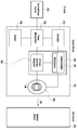
도 2는, 다양한 실시예들에 따른, 전력 관리 모듈 및 배터리에 대한 블럭도이다.
도 3은 제 1 전자 장치와 제 2 전자 장치 간에 무선으로 전력을 공유하기 위한 기본 개념도이다.
도 4는 본 발명의 다양한 실시예에 따른 전자 장치의 개략적인 단면도이다.
도 5는 다양한 실시예에 따른 전자 장치에서 충전 회로의 개념을 설명하기 위한 개념도이다.
도 6a 및 도 6b는 전자 장치의 무선 충전 기능을 이용해 웨어러블 장치를 무선 충전하는 사용자 시나리오의 예시이다.
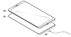
도 7a 및 도 7b는 전자 장치의 무선 충전 기능을 이용해 외부 전자 장치를 무선 충전하는 사용자 시나리오의 예시이다.
도 8은 일 실시예에 따른 전자 장치의 무선 전력 회로가 Tx 모드인 경우를 설명한 블록도이다.
도 9는 일 실시예에 따른 전자 장치의 무선 전력 회로가 Rx 모드인 경우를 설명한 블록도이다.
도 10은 일 실시예에 따른 전자 장치의 동작을 나타낸 흐름도이다.1 is a block diagram of an electronic device in a network environment according to various embodiments.
2 is a block diagram of a power management module and battery, in accordance with various embodiments.
3 is a basic conceptual diagram for wirelessly sharing power between a first electronic device and a second electronic device.
4 is a schematic cross-sectional view of an electronic device according to various embodiments of the present disclosure.
5 is a conceptual diagram illustrating a concept of a charging circuit in an electronic device according to various embodiments of the present disclosure.
6A and 6B are examples of user scenarios for wirelessly charging a wearable device using a wireless charging function of an electronic device.
7A and 7B are examples of user scenarios for wirelessly charging an external electronic device using the wireless charging function of the electronic device.
8 is a block diagram illustrating a case where a wireless power circuit of an electronic device according to an embodiment is in a Tx mode.
9 is a block diagram illustrating a case where a wireless power circuit of an electronic device according to an embodiment is in an Rx mode.
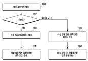
10 is a flowchart illustrating an operation of an electronic device according to an embodiment.
도 1은, 다양한 실시예들에 따른, 네트워크 환경(100) 내의 전자 장치(101)의 블럭도이다. 도 1을 참조하면, 네트워크 환경(100)에서 전자 장치(101)는 제 1 네트워크(198)(예: 근거리 무선 통신 네트워크)를 통하여 전자 장치(102)와 통신하거나, 또는 제 2 네트워크(199)(예: 원거리 무선 통신 네트워크)를 통하여 전자 장치(104) 또는 서버(108)와 통신할 수 있다. 일 실시예에 따르면, 전자 장치(101)는 서버(108)를 통하여 전자 장치(104)와 통신할 수 있다. 일 실시예에 따르면, 전자 장치(101)는 프로세서(120), 메모리(130), 입력 장치(150), 음향 출력 장치(155), 표시 장치(160), 오디오 모듈(170), 센서 모듈(176), 인터페이스(177), 햅틱 모듈(179), 카메라 모듈(180), 전력 관리 모듈(188), 배터리(189), 통신 모듈(190), 가입자 식별 모듈(196), 또는 안테나 모듈(197)을 포함할 수 있다. 어떤 실시예에서는, 전자 장치(101)에는, 이 구성요소들 중 적어도 하나(예: 표시 장치(160) 또는 카메라 모듈(180))가 생략되거나, 하나 이상의 다른 구성 요소가 추가될 수 있다. 어떤 실시예에서는, 이 구성요소들 중 일부들은 하나의 통합된 회로로 구현될 수 있다. 예를 들면, 센서 모듈(176)(예: 지문 센서, 홍채 센서, 또는 조도 센서)은 표시 장치(160)(예: 디스플레이)에 임베디드된 채 구현될 수 있다.1 is a block diagram of an
프로세서(120)는, 예를 들면, 소프트웨어(예: 프로그램(140))를 실행하여 프로세서(120)에 연결된 전자 장치(101)의 적어도 하나의 다른 구성요소(예: 하드웨어 또는 소프트웨어 구성요소)을 제어할 수 있고, 다양한 데이터 처리 또는 연산을 수행할 수 있다. 일 실시예에 따르면, 데이터 처리 또는 연산의 적어도 일부로서, 프로세서(120)는 다른 구성요소(예: 센서 모듈(176) 또는 통신 모듈(190))로부터 수신된 명령 또는 데이터를 휘발성 메모리(132)에 로드하고, 휘발성 메모리(132)에 저장된 명령 또는 데이터를 처리하고, 결과 데이터를 비휘발성 메모리(134)에 저장할 수 있다. 일 실시예에 따르면, 프로세서(120)는 메인 프로세서(121)(예: 중앙 처리 장치 또는 어플리케이션 프로세서), 및 이와는 독립적으로 또는 함께 운영 가능한 보조 프로세서(123)(예: 그래픽 처리 장치, 이미지 시그널 프로세서, 센서 허브 프로세서, 또는 커뮤니케이션 프로세서)를 포함할 수 있다. 추가적으로 또는 대체적으로, 보조 프로세서(123)은 메인 프로세서(121)보다 저전력을 사용하거나, 또는 지정된 기능에 특화되도록 설정될 수 있다. 보조 프로세서(123)는 메인 프로세서(121)와 별개로, 또는 그 일부로서 구현될 수 있다.The
보조 프로세서(123)는, 예를 들면, 메인 프로세서(121)가 인액티브(예: 슬립) 상태에 있는 동안 메인 프로세서(121)를 대신하여, 또는 메인 프로세서(121)가 액티브(예: 어플리케이션 실행) 상태에 있는 동안 메인 프로세서(121)와 함께, 전자 장치(101)의 구성요소들 중 적어도 하나의 구성요소(예: 표시 장치(160), 센서 모듈(176), 또는 통신 모듈(190))와 관련된 기능 또는 상태들의 적어도 일부를 제어할 수 있다. 일 실시예에 따르면, 보조 프로세서(123)(예: 이미지 시그널 프로세서 또는 커뮤니케이션 프로세서)는 기능적으로 관련 있는 다른 구성 요소(예: 카메라 모듈(180) 또는 통신 모듈(190))의 일부로서 구현될 수 있다.The
메모리(130)는, 전자 장치(101)의 적어도 하나의 구성요소(예: 프로세서(120) 또는 센서모듈(176))에 의해 사용되는 다양한 데이터를 저장할 수 있다. 데이터는, 예를 들어, 소프트웨어(예: 프로그램(140)) 및, 이와 관련된 명령에 대한 입력 데이터 또는 출력 데이터를 포함할 수 있다. 메모리(130)는, 휘발성 메모리(132) 또는 비휘발성 메모리(134)를 포함할 수 있다.The
프로그램(140)은 메모리(130)에 소프트웨어로서 저장될 수 있으며, 예를 들면, 운영 체제(142), 미들 웨어(144) 또는 어플리케이션(146)을 포함할 수 있다.The
입력 장치(150)는, 전자 장치(101)의 구성요소(예: 프로세서(120))에 사용될 명령 또는 데이터를 전자 장치(101)의 외부(예: 사용자)로부터 수신할 수 있다. 입력 장치(150)은, 예를 들면, 마이크, 마우스, 키보드, 또는 디지털 펜(예:스타일러스 펜)을 포함할 수 있다.The
음향 출력 장치(155)는 음향 신호를 전자 장치(101)의 외부로 출력할 수 있다. 음향 출력 장치(155)는, 예를 들면, 스피커 또는 리시버를 포함할 수 있다. 스피커는 멀티미디어 재생 또는 녹음 재생과 같이 일반적인 용도로 사용될 수 있고, 리시버는 착신 전화를 수신하기 위해 사용될 수 있다. 일 실시예에 따르면, 리시버는 스피커와 별개로, 또는 그 일부로서 구현될 수 있다.The
표시 장치(160)는 전자 장치(101)의 외부(예: 사용자)로 정보를 시각적으로 제공할 수 있다. 표시 장치(160)은, 예를 들면, 디스플레이, 홀로그램 장치, 또는 프로젝터 및 해당 장치를 제어하기 위한 제어 회로를 포함할 수 있다. 일 실시예에 따르면, 표시 장치(160)는 터치를 감지하도록 설정된 터치 회로(touch circuitry), 또는 상기 터치에 의해 발생되는 힘의 세기를 측정하도록 설정된 센서 회로(예: 압력 센서)를 포함할 수 있다.The
오디오 모듈(170)은 소리를 전기 신호로 변환시키거나, 반대로 전기 신호를 소리로 변환시킬 수 있다. 일 실시예에 따르면, 오디오 모듈(170)은, 입력 장치(150)를 통해 소리를 획득하거나, 음향 출력 장치(155), 또는 전자 장치(101)와 직접 또는 무선으로 연결된 외부 전자 장치(예: 전자 장치(102)) (예: 스피커 또는 헤드폰))를 통해 소리를 출력할 수 있다.The
센서 모듈(176)은 전자 장치(101)의 작동 상태(예: 전력 또는 온도), 또는 외부의 환경 상태(예: 사용자 상태)를 감지하고, 감지된 상태에 대응하는 전기 신호 또는 데이터 값을 생성할 수 있다. 일 실시예에 따르면, 센서 모듈(176)은, 예를 들면, 제스처 센서, 자이로 센서, 기압 센서, 마그네틱 센서, 가속도 센서, 그립 센서, 근접 센서, 컬러 센서, IR(infrared) 센서, 생체 센서, 온도 센서, 습도 센서, 또는 조도 센서를 포함할 수 있다.The
인터페이스(177)는 전자 장치(101)이 외부 전자 장치(예: 전자 장치(102))와 직접 또는 무선으로 연결되기 위해 사용될 수 있는 하나 이상의 지정된 프로토콜들을 지원할 수 있다. 일 실시예에 따르면, 인터페이스(177)는, 예를 들면, HDMI(high definition multimedia interface), USB(universal serial bus) 인터페이스, SD카드 인터페이스, 또는 오디오 인터페이스를 포함할 수 있다.The
연결 단자(178)는, 그를 통해서 전자 장치(101)가 외부 전자 장치(예: 전자 장치(102))와 물리적으로 연결될 수 있는 커넥터를 포함할 수 있다. 일 실시예에 따르면, 연결 단자(178)은, 예를 들면, HDMI 커넥터, USB 커넥터, SD 카드 커넥터, 또는 오디오 커넥터(예: 헤드폰 커넥터)를 포함할 수 있다.The
햅틱 모듈(179)은 전기적 신호를 사용자가 촉각 또는 운동 감각을 통해서 인지할 수 있는 기계적인 자극(예: 진동 또는 움직임) 또는 전기적인 자극으로 변환할 수 있다. 일 실시예에 따르면, 햅틱 모듈(179)은, 예를 들면, 모터, 압전 소자, 또는 전기 자극 장치를 포함할 수 있다.The
카메라 모듈(180)은 정지 영상 및 동영상을 촬영할 수 있다. 일 실시예에 따르면, 카메라 모듈(180)은 하나 이상의 렌즈들, 이미지 센서들, 이미지 시그널 프로세서들, 또는 플래시들을 포함할 수 있다.The
전력 관리 모듈(188)은 전자 장치(101)에 공급되는 전력을 관리할 수 있다. 일 실시예에 따르면, 전력 관리 모듈(388)은, 예를 들면, PMIC(power management integrated circuit)의 적어도 일부로서 구현될 수 있다.The
배터리(189)는 전자 장치(101)의 적어도 하나의 구성 요소에 전력을 공급할 수 있다. 일 실시예에 따르면, 배터리(189)는, 예를 들면, 재충전 불가능한 1차 전지, 재충전 가능한 2차 전지 또는 연료 전지를 포함할 수 있다.The
통신 모듈(190)은 전자 장치(101)와 외부 전자 장치(예: 전자 장치(102), 전자 장치(104), 또는 서버(108))간의 직접(예: 유선) 통신 채널 또는 무선 통신 채널의 수립, 및 수립된 통신 채널을 통한 통신 수행을 지원할 수 있다. 통신 모듈(190)은 프로세서(120)(예: 어플리케이션 프로세서)와 독립적으로 운영되고, 직접(예: 유선) 통신 또는 무선 통신을 지원하는 하나 이상의 커뮤니케이션 프로세서를 포함할 수 있다. 일 실시예에 따르면, 통신 모듈(190)은 무선 통신 모듈(192)(예: 셀룰러 통신 모듈, 근거리 무선 통신 모듈, 또는 GNSS(global navigation satellite system) 통신 모듈) 또는 유선 통신 모듈(194)(예: LAN(local area network) 통신 모듈, 또는 전력선 통신 모듈)을 포함할 수 있다. 이들 통신 모듈 중 해당하는 통신 모듈은 제 1 네트워크(198)(예: 블루투스, WiFi direct 또는 IrDA(infrared data association) 같은 근거리 통신 네트워크) 또는 제 2 네트워크(199)(예: 셀룰러 네트워크, 인터넷, 또는 컴퓨터 네트워크(예: LAN 또는 WAN)와 같은 원거리 통신 네트워크)를 통하여 외부 전자 장치와 통신할 수 있다. 이런 여러 종류의 통신 모듈들은 하나의 구성 요소(예: 단일 칩)으로 통합되거나, 또는 서로 별도의 복수의 구성 요소들(예: 복수 칩들)로 구현될 수 있다. 무선 통신 모듈(192)은 가입자 식별 모듈(196)에 저장된 가입자 정보(예: 국제 모바일 가입자 식별자(IMSI))를 이용하여 제 1 네트워크(198) 또는 제 2 네트워크(199)와 같은 통신 네트워크 내에서 전자 장치(101)를 확인 및 인증할 수 있다. The
안테나 모듈(197)은 신호 또는 전력을 외부(예: 외부 전자 장치)로 송신하거나 외부로부터 수신할 수 있다. 일 실시예에 따르면, 안테나 모듈은 서브스트레이트(예: PCB) 위에 형성된 도전체 또는 도전성 패턴으로 이루어진 방사체를 포함하는 하나의 안테나를 포함할 수 있다. 일 실시예에 따르면, 안테나 모듈(197)은 복수의 안테나들을 포함할 수 있다. 이런 경우, 제 1 네트워크(198) 또는 제 2 네트워크(199)와 같은 통신 네트워크에서 사용되는 통신 방식에 적합한 적어도 하나의 안테나가, 예를 들면, 통신 모듈(190)에 의하여 상기 복수의 안테나들로부터 선택될 수 있다. 신호 또는 전력은 상기 선택된 적어도 하나의 안테나를 통하여 통신 모듈(190)과 외부 전자 장치 간에 송신되거나 수신될 수 있다. 어떤 실시예에 따르면, 방사체 이외에 다른 부품(예: RFIC)이 추가로 안테나 모듈(197)의 일부로 형성될 수 있다.The
상기 구성요소들 중 적어도 일부는 주변 기기들간 통신 방식(예: 버스, GPIO(general purpose input and output), SPI(serial peripheral interface), 또는 MIPI(mobile industry processor interface))를 통해 서로 연결되고 신호(예: 명령 또는 데이터)를 상호간에 교환할 수 있다.At least some of the components are connected to each other through a communication method between peripheral devices (for example, a bus, a general purpose input and output (GPIO), a serial peripheral interface (SPI), or a mobile industry processor interface (MIPI)) and a signal ( Ex: command or data) can be exchanged with each other.
일 실시예에 따르면, 명령 또는 데이터는 제 2 네트워크(199)에 연결된 서버(108)를 통해서 전자 장치(101)와 외부의 전자 장치(104)간에 송신 또는 수신될 수 있다. 전자 장치(102, 104) 각각은 전자 장치(101)와 동일한 또는 다른 종류의 장치일 수 있다. 일 실시예에 따르면, 전자 장치(101)에서 실행되는 동작들의 전부 또는 일부는 외부 전자 장치들(102, 104, or 108) 중 하나 이상의 외부 장치들에서 실행될 수 있다. 예를 들면, 전자 장치(101)가 어떤 기능이나 서비스를 자동으로, 또는 사용자 또는 다른 장치로부터의 요청에 반응하여 수행해야 할 경우에, 전자 장치(101)는 기능 또는 서비스를 자체적으로 실행시키는 대신에 또는 추가적으로, 하나 이상의 외부 전자 장치들에게 그 기능 또는 그 서비스의 적어도 일부를 수행하라고 요청할 수 있다. 상기 요청을 수신한 하나 이상의 외부 전자 장치들은 요청된 기능 또는 서비스의 적어도 일부, 또는 상기 요청과 관련된 추가 기능 또는 서비스를 실행하고, 그 실행의 결과를 전자 장치(101)로 전달할 수 있다. 전자 장치(101)는 상기 결과를, 그대로 또는 추가적으로 처리하여, 상기 요청에 대한 응답의 적어도 일부로서 제공할 수 있다. 이를 위하여, 예를 들면, 클라우드 컴퓨팅, 분산 컴퓨팅, 또는 클라이언트-서버 컴퓨팅 기술이 이용될 수 있다.According to an embodiment, the command or data may be transmitted or received between the
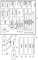
도 2는, 다양한 실시예들에 따른, 전력 관리 모듈(예: 188) 및 배터리(예: 189)에 대한 블럭도(200)이다. 도 2를 참조하면, 전력 관리 모듈(188)은 충전 회로(210), 전력 조정기(220), 또는 연료 게이지(230)를 포함할 수 있다. 충전 회로(210)는 전자 장치(101)에 대한 외부 전원으로부터 공급되는 전력을 이용하여 배터리(189)를 충전할 수 있다. 일 실시예에 따르면, 충전 회로(210)는 외부 전원의 종류(예: 전원 어댑터, USB 또는 무선 충전), 상기 외부 전원으로부터 공급 가능한 전력의 크기(예: 약 20와트 이상), 또는 배터리(189)의 속성 중 적어도 일부에 기반하여 충전 방식(예: 일반 충전 또는 급속 충전)을 선택하고, 상기 선택된 충전 방식을 이용하여 배터리(189)를 충전할 수 있다. 외부 전원은, 예를 들면, 연결 단자(예: 178)을 통해 유선 연결되거나, 또는 안테나 모듈(예: 197)를 통해 무선으로 연결될 수 있다.2 is a block diagram 200 for a power management module (eg, 188) and a battery (eg, 189), according to various embodiments. Referring to FIG. 2, the
전력 조정기(220)는 외부 전원 또는 배터리(189)로부터 공급되는 전력의 전압 레벨 또는 전류 레벨을 조정함으로써 다른 전압 또는 다른 전류 레벨을 갖는 복수의 전력들을 생성할 수 있다. 전력 조정기(220)는 상기 외부 전원 또는 배터리(189)의 전력을 전자 장치(101)에 포함된 구성 요소들의 각각의 구성 요소에게 적합한 전압 또는 전류 레벨로 조정할 수 있다. 일 실시예에 따르면, 전력 조정기(220)는 LDO(low drop out) regulator 또는 switching regulator의 형태로 구현될 수 있다.The
연료 게이지(230)는 배터리(189)의 사용 상태 정보(예: 배터리의 용량, 충방전 횟수, 전압, 또는 온도)를 측정할 수 있다.The
전력 관리 모듈(188)은, 예를 들면, 충전 회로(210), 전압 조정기(220), 또는 연료 게이지(230)를 이용하여, 상기 측정된 사용 상태 정보에 적어도 일부 기반하여 배터리(189)의 충전과 관련된 충전 상태 정보(예: 수명, 과전압, 저전압, 과전류, 과충전, 과방전(over discharge), 과열, 단락, 또는 팽창(swelling)을 결정하고, 상기 결정된 충전 상태 정보에 적어도 일부 기반하여 배터리(189)의 이상 상태 또는 정상 상태의 여부를 판단한 후, 이상 상태로 판단되는 경우 배터리(189)에 대한 충전을 조정(예: 충전 전류 또는 전압 감소, 또는 충전 중지)할 수 있다. 일 실시예에 따르면, 전력 관리 모듈(188)의 기능들 중 적어도 일부 기능은 외부 제어 장치(예: 프로세서(120))에 의해서 수행될 수 있다.The
배터리(189)는, 예를 들면, 배터리 보호 회로(protection circuit module(PCM))(240)를 포함할 수 있다. 배터리 보호 회로(240)는 배터리(189)의 성능 저하 또는 소손을 방지하기 위한 다양한 기능(예: 사전 차단 기능)을 수행할 수 있다. 배터리 보호 회로(240)은, 추가적으로 또는 대체적으로(in alternative to), 셀 밸런싱, 배터리의 용량 측정, 충방전 횟수 측정, 온도 측정, 또는 전압 측정을 수행하기 위한 배터리 관리 시스템(battery management system(BMS))의 적어도 일부로서 구성될 수 있다.The
일 실시예에 따르면, 배터리(189)의 상기 사용 상태 정보 또는 상기 충전 상태 정보의 적어도 일부는 연료 게이지(230), 전력 관리 모듈(188) 또는 센서 모듈(276) 중 해당하는 센서(예: 온도 센서)을 이용하여 측정될 수 있다. 이런 경우, 일 실시예에 따르면, 상기 센서 모듈(176) 중 상기 해당하는 센서(예: 온도 센서)는 배터리 보호 회로(140)의 일부로 포함되거나, 또는 이와는 별도의 장치로서 배터리(189)의 인근에 배치될 수 있다.According to an embodiment, at least a portion of the usage state information or the charging state information of the
본 발명의 다양한 실시예에 따른 전자 장치(예: 도 8의 전자 장치(801))는 배터리(예: 도 8의 배터리(830)), 배터리(830)의 충전 상태를 제어하는 PMIC(예: 도 8의 PMIC(820)), 코일(예: 도 8의 코일(850)), 상기 코일(850)과 전기적 연결된 무선 전력 회로(예: 도 8의 무선 충전 IC(840)), 상기 코일(예: 도 8의 코일(850))과 전기적 연결된 통신 회로(예: 도 8의 통신 회로(841)), 및 프로세서(예: 도 8의 제어 회로(810))를 포함하고, 상기 프로세서(810)는, 상기 무선 전력 회로(840)가 Tx 모드인 경우, 상기 무선 전력 회로(840)를 이용하여 무선 전력 신호를 상기 코일(850) 통하여 전송 및 상기 통신 회로(841)를 이용하여 송신 장치 파라미터를 FSK(frequency shift keying) 모듈레이션한 신호를 상기 코일(850)을 통해 외부 전자 장치(802)로 전송하고, 상기 무선 전력 회로(840)가 Rx 모드인 경우, 상기 무선 전력 회로(840)를 이용하여 무선 전력을 수신하여 배터리(830)를 충전 및 상기 통신 회로(841)를 이용하여 수신 장치 파라미터를 ASK(amplitude shift keying) 모듈레이션한 신호를 상기 코일(850)을 통해 외부 전자 장치(802)로 전송하도록 설정될 수 있다. 상기 무선 전력 신호는 110kHz~190kHz 대역의 무선 신호일 수 있다. 상기 프로세서(810)는 상기 무선 전력 회로(840)가 상기 Tx 모드인 경우, 상기 통신 회로(841)를 이용하여 상기 송신 장치 파라미터를 상기 무선 전력 신호의 대역 대비 △0.2%~5% 인근 대역의 신호로 FSK 모듈레이션하도록 설정될 수 있다. 상기 프로세서(810)는 상기 무선 전력 회로(840)가 상기 Tx 모드인 경우, 스케일링 인자(scaling factor)를 포함하는 뎁스(depth)를 0으로 설정하고, 상기 송신 장치 파라미터를 상기 무선 전력 신호의 대역 대비 △0.3% 인근 대역의 신호로 FSK 모듈레이션하도록 설정될 수 있다. 상기 프로세서(810)는 상기 무선 전력 회로(840)가 상기 Tx 모드인 경우, 스케일링 인자(scaling factor)를 포함하는 뎁스(depth)를 3으로 설정하고, 상기 송신 장치 파라미터를 상기 무선 전력 신호의 대역 대비 △3.2% 인근 대역의 신호로 FSK 모듈레이션하도록 설정될 수 있다. 상기 송신 장치 파라미터는 상기 전자 장치(801)의 식별 정보, 상기 배터리(830) 정보, 상기 전자 장치(801)에 연결된 TA(travel adapter) 정보, 상기 배터리(830) 및 상기 TA 정보를 기반하여 공급할 수 있는 전력 정보, 또는 전송 모드 정보 중에서 적어도 하나를 포함할 수 있다. 상기 프로세서(810)는 상기 무선 전력 회로(840)가 Tx 모드인 경우, 상기 송신 장치 파라미터를 모듈레이션한 신호에 대한 응답 신호를 상기 외부 전자 장치(802)로부터 수신하고, 상기 응답 신호에 기반하여 결정된 지정된 무선 전력 신호를 상기 코일(850) 통하여 전송하도록 설정될 수 있다. 상기 프로세서(810)는 상기 무선 전력 회로(840)가 상기 Rx 모드인 경우, 상기 통신 회로(841)를 이용하여 상기 수신 장치 파라미터를 상기 수신된 무선 전력의 전압 대비 △1%~30% 의 전압 변화를 갖는 신호로 ASK 모듈레이션 하도록 설정될 수 있다. 상기 수신 장치 파라미터는 충전 모드(전압, 전류, 전력) 변경 요청 정보, 상기 전자 장치(801)의 식별 정보, 수신 가능한 전력 정보, 수신 전력 상태 정보, 또는 상기 배터리(830) 정보 중에서 적어도 하나를 포함할 수 있다.An electronic device (eg, the
본 발명의 다양한 실시예는 무선 전력 전송 기술을 이용하여 전자 장치와 전자 장치 간 전력을 공유(전송)하는 방법에 관한 것일 수 있다. 다양한 실시예에 따르면 전자 장치는 무선 전력을 수신하는 외부 전자 장치의 충전 전력량에 기반하여 충전 회로를 제어하여 송신 전력을 조정할 수 있다. 다양한 실시예에 따르면, 전자 장치는 무선 충전시 상대적으로 고전력을 필요로 하는 외부 전자 장치(예: 스마트폰)에게 전력을 송신하거나, 또는 무선 충전시 상대적으로 저전력을 필요로 하는 외부 전자 장치(예: 웨어러블 장치)에게 전력을 송신할 수 있고, 상기 외부 전자 장치의 종류에 기반하여 송신 전력을 조정할 수 있다.Various embodiments of the present invention may relate to a method of sharing (transmitting) power between an electronic device and an electronic device using a wireless power transmission technology. According to various embodiments, the electronic device may adjust the transmission power by controlling the charging circuit based on the amount of charging power of the external electronic device receiving wireless power. According to various embodiments, the electronic device transmits power to an external electronic device (eg, a smart phone) that requires relatively high power when charging wirelessly, or an external electronic device (eg, a relatively low power when wireless charging) : Wearable device), and transmit power may be adjusted based on the type of the external electronic device.
도 3은 제 1 전자 장치와 제 2 전자 장치 간에 무선으로 전력을 공유하기 위한 기본 개념도이다.3 is a basic conceptual diagram for wirelessly sharing power between a first electronic device and a second electronic device.
도 3에서는, 제 1 전자 장치(301)(예: 도 1의 전자 장치(101))와 제 2 전자 장치(302)(예: 도 1의 전자 장치(102))가 모두 무선 전력 송/수신이 가능한 장치로 표현하였으나 둘 중 하나의 장치가 무선 전력 수신만 가능한 전자 장치일 수도 있다. 본 문서에서는 제 1 전자 장치(301)를 기준으로 설명하고, 제 2 전자 장치(302)는 외부 전자 장치인 것으로 설명하되, 제 2 전자 장치(302)는 제 1 전자 장치(301)와 동일한 구성이거나 무선 전력 송신 기능만 제거된 구성일 수 있다.In FIG. 3, both the first electronic device 301 (eg, the
일 실시예에 따르면, 제 1 전자 장치(301)는 코일(350), 무선 충전 IC(340), PMIC(320)(power management IC)(예: 도 2의 전력 관리 모듈(288)), 배터리(330)(예: 도 1의 배터리(189)), 외부 연결 단자(303)(예: USB), 및/또는 제어 회로(310)(controller)(예: 도 1의 프로세서(120))를 포함할 수 있다.According to an embodiment, the first
일 실시예에 따르면, 코일(350)은 FPCB에 나선형으로 형성될 수 있다.According to one embodiment, the
일 실시예에 따르면, 무선 충전 IC(340)는 full bridge 회로를 포함할 수 있다. 예를 들면, 무선 충전 IC(340)는 무선 전력 송신 동작에서 상기 full bridge회로를 inverter(DC → AC)로 구동하도록 제어하고, 무선 전력 수신 동작에서는 full bridge 회로를 rectifier (AC → DC)로 구동하도록 제어할 수 있다.According to an embodiment, the
일 실시예에 따르면, 무선 충전 IC(340)는 WPC 표준(또는 비표준)에 적어도 일부에 따라 제 2 전자 장치(302)와 인-밴드(in-band) 통신을 통해 무선 전력 전송에 필요한 정보들을 교환할 수 있다. 예를 들면, 인-밴드 통신은 코일(350)과 코일(350)간의 무선 전력 전송 상황에서 무선 전력 전송 신호의 frequency나 amplitude 모듈레이션을 통해 제 1 전자 장치(301) 및 제 2 전자 장치(302)들 간에 데이터를 교환할 수 있는 방식일 수 있다. 다양한 실시예에 따르면 제 1 전자 장치(301) 및 제 2 전자 장치(302)들 간의 통신은 아웃-밴드(out-band)통신을 이용할 수도 있다. 예를 들면, 아웃-밴드 통신은 무선 전력 신호와는 다른 것으로, NFC, 블루투스, 또는 WiFi 와 같은 근거리 통신일 수 있다.According to an embodiment, the
일 실시예에 따르면, PMIC(320)는 유선 및 무선 입력 전원을 배터리(330)로 충전하는 charger 기능, USB 단자에 연결된 외부 전원 장치(예: travel adapter)와 통신(예: USB battery charging 스펙, USB PD(power delivery)통신, AFC 통신, 및/또는 QC(quick charge) 통신)하는 기능, 시스템으로 필요한 전력을 공급 및 각 소자마다 필요로 하는 전압 레벨에 맞는 전원을 공급해주는 기능, 및/또는 무선 전력 송신 모드에서 무선 충전 IC(340)로 전력을 공급하는 기능을 포함할 수 있다.According to one embodiment, the
일 실시예에 따르면, 외부 연결 단자(303, 304)는 USB 표준을 따르는 단자일 수 있다. 예를 들면, 외부 연결 단자(303, 304)는 USB 충전, 및/또는 OTG(on the go) 전원 공급을 하기 위한 인터페이스일 수 있다. 일 실시예에 따르면, 외부 연결 단자(303, 304)는 외부 전원 소스(TA, 또는 Battery pack 등)가 연결될 수 있다.According to an embodiment, the
일 실시예에 따르면, 제어 회로(310)는 제 1전자 장치의 유무선 충전 및 제 2 전자 장치(302)와의 USB통신, 및/또는 제 2 전자 장치(302)와의 통신(예: USB PD, BC1.2, AFC, 및/또는 QC)의 기능을 제 1 전자 장치(301)의 상황에 따라 통합적으로 제어할 수 있다. 예를 들면, BC1.2 또는 PD 등은 외부 전원 소스 (TA)와 통신하는 인터페이스일 수 있고, 상기 제어 회로(310)는, 외부 전원 소스와의 통신을 제어할 수 있다. 예를 들면, 제 1 전자 장치(301)의 상황은, 제 1 전자 장치(301)의 온도, 및/또는 제 1 전자 장치(301)의 배터리(330)의 용량을 포함할 수 있다.According to an embodiment, the
다양한 실시예에 따르면 제 1 전자 장치(301)는 배터리(330)를 이용하여 무선 전력 Tx mode로 동작할 수 있다. 또는, 제 1 전자 장치(301)는 유선 전력 공급 장치가 연결되어 있을 경우 외부 전원을 Tx mode에 우선적으로 활용하고 남은 전력을 배터리(330)로 충전할 수 있다. 제 1 전자 장치(301)는 유선 전력 공급 장치가 연결되어 있을 경우 외부 전원(전력)을 무선 충전 IC(340) 공급하고 나머지의 적어도 일부 전원(전력)을 배터리(330)로 공급할 수 있다. According to various embodiments, the first
본 문서에서 전자 장치(예: 도 3의 제 1 전자 장치(301))가 무선 전력 Tx mode로 동작하는 것은, 상기 전자 장치가 코일(350)을 이용하여 외부 전자 장치(예: 도 3의 제 2 전자 장치(302))에게 무선 전력을 전송하는 상태인 것을 의미할 수 있다. 또는, 본 문서에서 전자 장치(301)가 무전 전력 Rx mode로 동작하는 것은, 상기 전자 장치(301)가 코일(350)을 통해 외부 전자 장치(예: 도 3의 제 2 전자 장치(302))로부터 무선 전력을 수신하고, 수신된 무선 전력을 이용하여 배터리(330)를 충전하는 상태인 것을 의미할 수 있다.In this document, when an electronic device (eg, the first
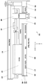
도 4는 본 발명의 다양한 실시예에 따른 전자 장치의 개략적인 단면도이다.4 is a schematic cross-sectional view of an electronic device according to various embodiments of the present disclosure.
도 4를 참조하면, 전자 장치(400)(예: 도 1의 전자 장치(101))는 하나 이상의 부품들을 수용 및 고정하는 하우징(405), 또는 전자 장치(400)의 뒷면에서 하우징(405)과 체결되는 커버(409)를 포함할 수 있다. 예를 들면, 부품들은 하우징(405) 내부에 위치한, 디스플레이 패널(411), 기판(401), 배터리(407)(예: 도 1의 배터리(189)), 카메라(403), 또는 FPCB(415)를 포함할 수 있다.Referring to FIG. 4, the electronic device 400 (eg, the
일 실시예에 따르면, 디스플레이 패널(411)은 전자 장치의 앞면에 위치하고 글래스(윈도우 커버)(423)가 상면에 부착될 수 있다. 일 실시예에 따르면, 디스플레이 패널(411)은 터치 센서또는 압력 센서와 일체로 형성될 수 있다. 다른 실시예에 따르면, 터치 센서 또는 압력 센서는 디스플레이 패널(411)과는 별도로 분리될 수 있다. 예를 들면, 터치 센서는 글래스(423)와 디스플레이 패널(411) 사이에 위치할 수 있다.According to an embodiment, the
일 실시예에 따르면, 기판(401)은 통신 모듈(예: 도 1의 통신 모듈(190)), 또는 프로세서(예: 도 1의 프로세서(120))와 같은 부품들을 탑재할 수 있다. 일 실시예에 따르면, 기판(401)은 PCB(printed circuit board) 또는 FPCB(flexible printed circuit board) 중 적어도 하나를 이용하여 구현될 수 있다. 일 실시예에 따르면, 기판(401)은 루프 안테나(417)를 접지(ground)시킬 수 있는 접지 판(ground plate)으로서 동작할 수 있다.According to an embodiment, the
일 실시예에 따르면, 커버(409)는 도전성 물질로 이루어진 도전 영역과 비도전성 물질로 이루어진 비도전 영역으로 구분될 수 있다. 예를 들면, 커버(409)는 도전 영역과, 도전 영역의 일측 또는 양측 각각에 위치한 비도전 영역으로 구분될 수 있다. 일 실시예에 따르면, 커버(409)에는 전자 장치(400)의 일부 부품을 외부로 노출하기 위한 적어도 하나 이상의 오프닝(421)이 형성될 수 있다. 예를 들면, 커버(409)는 카메라(403), 플래쉬, 또는 센서(예: 지문 센서)를 노출시키기 위한 하나 이상의 오프닝(421)을 포함할 수 있다.According to an embodiment, the
일 실시예에 따르면, FPCB(415)는 커버(409)의 하면에 부착될 수 있다. 일 실시예에 따르면, FPCB(415)는 하나 이상의 루프 안테나(417)를 탑재할 수 있고, 커버(409)의 도전 영역과 전기적으로 절연되게 위치할 수 있다.According to one embodiment, the
일 실시예에 따르면, 하나 이상의 루프 안테나(417)는 서로 동일한 타입으로 형성될 수 있다. 예를 들면, 하나 이상의 루프 안테나(417)는 평면 타입의 코일로 형성될 수 있다. 다른 실시예에 따르면, 하나 이상의 루프 안테나(417) 중에서 일부는 평면 타입의 코일로 형성되고, 다른 일부는 솔레노이드 타입의 코일로 형성될 수 있다.According to an embodiment, the one or
일 실시예에 따르면, 하나 이상의 루프 안테나(417)는 무선 충전 코일을 포함할 수 있고, 무선 충전 코일은 나선형의 패턴으로 형성될 수 있다.According to an embodiment, the one or
일 실시예에 따르면, 하나 이상의 루프 안테나(417)의 일측 방향에는 자기장 차폐층(shielding sheet(422) and graphite sheet(423))이 형성될 수 있다. 예를 들면, 자기장 차폐층(422, 423)은 코일로부터 발생되는 자기장의 방향을 전자 장치(400)의 뒷면 방향(예: 도 4의 Z 방향)으로 집중시키고, 전자 장치(400) 내부의 자기장 형성을 억제하여 다른 전자 부품의 이상 동작을 방지할 수 있다.According to an embodiment, a magnetic field shielding layer (shielding
도 5는 다양한 실시예에 따른 전자 장치에서 충전 회로의 개념을 설명하기 위한 개념도이다.5 is a conceptual diagram illustrating a concept of a charging circuit in an electronic device according to various embodiments of the present disclosure.
도 5를 참조하면, 다양한 실시예에 따른 전자 장치(501)(예: 도 1의 전자 장치(101))는 배터리(510)(예: 도 1의 배터리(189)), 유선 인터페이스(521), 무선 인터페이스(525), 및/또는 충전 회로(530)를 포함할 수 있다.Referring to FIG. 5, the
일 실시예에 따르면, 배터리(510)는 전자 장치(501)의 하우징(예: 도 4의 하우징(405)) 내에 장착될 수 있으며, 충전 가능할 수 있다. 배터리(510)는 예를 들면, 리튬 이온 전지(lithium-ion battery), 충전식 전지(rechargeable battery) 및/또는 태양 전지(solar battery)를 포함할 수 있다. According to an embodiment, the
일 실시예에 따르면, 유선 인터페이스(521) 및 무선 인터페이스(525)는 전자 장치의 하우징의 일부에 장착될 수 있으며, 각각 외부 장치와 연결 가능할 수 있다. 유선 인터페이스(521)는 예컨대 USB(universal serial bus) 커넥터(521-1)를 구비하고, 커넥터(521-1)를 통해 제1 외부 장치(502)와 유선으로 연결 가능할 수 있고, USB 충전, 및/또는 OTG(on the go) 전원 공급을 하기 위한 인터페이스이거나, 외부 전원 소스(TA, 또는 Battery pack 등)가 연결될 수 있다. 무선 인터페이스(525)는 코일(525-1)('도전성 패턴'이라고도 함)(예: 도 4의 하나 이상의 루프 안테나(417))과 TRX IC(transmit/receive integrated chip)(525-2)을 구비하고, 도전성 패턴(525-1)과 TRX IC(525-2)를 통해 제2 외부 장치(503)와 무선으로 전력을 송수신할 수 있다. 무선 전력은 자기장 유도 결합 방식, 공진 결합 방식, 또는 이들의 혼합 방식의 무선 전력 전송 방식을 이용하여 전력을 송수신할 수 있다. 일 실시예에 따르면 도전성 패턴(525-1)은 무선 전력을 송신하기 위한 제1 도전성 패턴 및 무선 전력을 수신하기 위한 제2 도전성 패턴을 포함할 수 있다.According to an embodiment, the
일 실시예에 따르면, 제1 외부 장치(502)는 유선 방식으로 연결 가능한 외부 장치로서, 유선 전력 공급 또는 유선 전력 수신 장치일 수 있다. 유선 전력 수신 장치는 OTG(on the go) 장치일 수 있다. OTG 장치는마우스, 키보드, USB 메모리 및 액세서리 등과 같이 전자 장치와 연결되어 전원을 공급 받는 장치일 수 있다. 이때 전자장치는 USB단자로 외부 전원을 공급해주는 OTG 모드로 동작할 수 있다. 유선 전력 공급 장치는 TA(travel adapter)와 같이 유선으로 연결되어 전자 장치에 전력을 공급하는 장치일 수 있다. 유선 전력 수신 장치는 유선으로 연결되어 전자 장치로부터 전력을 수신하여 내부 전원으로 사용할 수 있으며 유선 전력 수신 장치에 구비된 다른 배터리를 충전할 수 있다. 일 실시예에 따르면, 유선 인터페이스(521) 통해 전자 장치(501)와 연결되는 제1 외부 장치는 유선 HV(high voltage) 장치(예: AFC(adaptive fast charge), QC(quick charge)를 지원하는 장치)를 포함할 수 있다. 유선 HV 장치가 커넥터에 연결되는 경우 배터리(510)에서 공급되는 전압(예를 들면 5v)보다 높은 전압(예컨대 9v)의 전원이 유선 HV 장치에 공급되거나 수신될 수 있다.According to an embodiment, the first
일 실시예에 따르면, 제2 외부 장치(503)는 무선 전력 공급 장치 또는 무선 전력 수신 장치를 포함할 수 있다. 다양한 실시예에 따르면 무선 전력 공급 장치는 무선 충전 패드와 같이 제1 도전성 패턴을 이용하여 전자 장치에 무선 전력을 공급하는 장치일 수 있다. 무선 전력 수신 장치는 제2 도전성 패턴을 이용하여 전자 장치에서 공급하는 무선 전력을 수신할 수 있으며 수신된 전력을 무선 전력 수신 장치에 포함된 다른 배터리를 충전하는 장치일 수 있다. 일 실시예에 따르면, 무선 인터페이스(525) 통해 전자 장치(501)와 연결되는 제2 외부 장치(503)는 무선 HV(high voltage) 장치(예: AFC(adaptive fast charge), QC(quick charge))를 지원하는 장치)를 포함할 수 있다. 일 실시예에 따르면, 무선 HV 장치는 급속 충전을 지원하는 무선 충전 패드를 포함할 수 있다. 무선 충전 패드는 인밴드(inband) 통신을 통해 TRX IC(525-2)와 통신하여 고속 충전 수행 여부를 결정하거나, 별도 통신 모듈(블루투스, 또는 지그비(zigbee))을 이용해 고속 충전 수행 여부를 결정할 수 있다. 예를 들면, 전자 장치(501)은 TRX IC(525-2)를 통해 무선 충전 패드에게 예컨대 9V의 HV(high voltage) 충전을 요청할 수 있고, 무선 충전 패드는 전자 장치(501)로부터 HV 충전 요청에 따라 전자 장치(501)와 통신을 통해 고속 충전 가능 여부를 확인할 수 있다. 고속 충전 가능한 것이 확인되면 무선 충전 패드는 전자 장치(501)측으로 9V의 전력을 공급할 수 있다.According to an embodiment, the second
일 실시예에 따르면, 충전 회로(530)는 배터리(510)와 전기적으로 연결될 수 있으며, 유선 인터페이스(521)와 무선 인터페이스(525), 배터리(510)와 유선 인터페이스(521), 및 배터리(510)와 무선 인터페이스(525) 사이를 각각 전기적으로 연결하도록 구성될 수 있다. 충전 회로(530)는 배터리(510)와 도전성 패턴 (예컨대 제1 도전성 패턴)을 전기적으로 연결하여 무선으로 전력을 제2 외부 장치(예: 무선 전력 수신 장치)로 전송할 수 있고, 무선으로 전력을 외부로 전송함과 동시에 배터리(510)와 커넥터를 전기적으로 연결하여 유선으로 전력을 제1 외부 장치(예: 유선 전력 수신 장치)로 전송할 수 있도록 구성될 수 있다. 예를 들면, 충전 회로(530)는 배터리(510)에 의해 발생된 제 1 전력을 상기 제 1 전력보다 높은 제 2 전력으로 변경하여 제 2 전력의 적어도 일부인 제 3 전력을 상기 제 1 도전성 패턴을 통해 무선 전력 수신 장치로 전송할 수 있고, 제 2 전력의 적어도 다른 일부인 제 4 전력을 커넥터를 통해 OTG 장치 또는 유선 전력 수신 장치로 전송할 수 있다.According to one embodiment, the charging
일 실시예에 따르면 충전 회로(530)는 인터페이스 컨트롤러(529), 제1 스위치(532), 제2 스위치(534), 제어 로직(536), 스위치 그룹(538), 및/또는 충전 스위치(539)를 포함할 수 있다.According to one embodiment, the charging
일 실시예에 따르면, 인터페이스 컨트롤러(529)는 유선 인터페이스(521)에 연결된 제1 외부 장치(502)의 종류를 판단할 수 있고, 제1 외부 장치(502)와 AFC(adaptive fast charge) 통신을 통해 고속 충전을 지원하는지 판단할 수 있다. 일 실시예에 따르면, 인터페이스 컨트롤러(529)는 MUIC(micro usb interface IC) 또는 고속충전 (예: AFC(adaptive fast charge), QC(quick charge)) 인터페이스를 포함할 수 있다. 예를 들면, MUIC는 유선 인터페이스(521)에 연결된 제1 외부 장치(502)가 유선 전력 공급 장치인지, 유선 전력 수신 장치인지 판단할 수 있다. 예를 들면, 고속충전 인터페이스는 제1 외부 장치(502)와 통신을 통해 급속 충전 지원 여부를 결정할 수 있다. 급속 충전을 지원하는 경우, 제1 외부 장치(502)는 송수신 전력을 증가시킬 수 있다. 예를 들면, 제1 외부 장치(502)가 통상적으로 10W(5V/2A)의 전력을 전송하는 유선 전력 공급 장치인 경우, 급속 충전이 지원되면, 15W(9V/1.6V)의 전력을 전송할 수 있다.According to an embodiment, the
일 실시예에 따르면, 제1 스위치(532)는 적어도 하나 이상의 스위치를 포함할 수 있으며, 유선 인터페이스(521)를 통해 연결되는 장치(예컨대 OTG 장치), 또는 유선 전력 수신 장치로의 전력 출력 및 유선 전력 공급 장치로부터의 전력 입력을 제어할 수 있다. 예를 들면, 제1 스위치(532)는 OTG 장치, 또는 유선 전력 수신 장치로의 전력 출력 및 유선 전력 공급 장치로부터의 전력이 입력되도록 온 상태로 동작하거나, OTG 장치, 또는 유선 전력 수신 장치로의 전력 출력 및 유선 전력 공급 장치로부터의 전력이 입력되지 않도록 오프 상태로 동작할 수 있다.According to an embodiment, the
일 실시예에 따르면, 제2 스위치(534)는 적어도 하나 이상의 스위치를 포함할 수 있으며, 무선 인터페이스(525) 예컨대 도전성 패턴(525-1) 및 TRX IC(525-2)를 통해 무선 전력 공급 장치 및 무선 전력 수신 장치로부터의 전력 입력 및 출력을 제어할 수 있다. 예를 들면, 제2 스위치(534)는 무선 전력 공급 장치 또는 무선 전력 수신 장치로부터의 전력 입력 및 출력이 가능하도록 온 상태로 동작하거나, 무선 전력 공급 장치 또는 무선 전력 수신 장치로부터의 전력 입력 및 출력이 가능하지 않도록 오프 상태로 동작할 수 있다.According to one embodiment, the
일 실시예에 따르면, 제어 로직(536)은 제1 스위치(532) 및 제2 스위치(534) 중 적어도 하나로부터 입력되는 전력을 배터리(510) 충전에 적합한 충전 전압 및 충전 전류로 변환하도록 제어할 수 있고, 배터리(510)로부터의 전력을 제1 스위치(532) 및 제2 스위치(534) 각각에 연결된 외부 장치의 다른 배터리 충전에 적합한 충전 전압 및 충전 전류로 변환하도록 제어할 수 있고, 배터리(510)로부터의 전력을 외부 장치에서 사용하기 적합한 전압 및 전류로 변환하도록 제어할 수 있다.According to an embodiment, the
다양한 실시예에 따르면, 제어 로직(536)은 충전 회로(530)가 선택적으로 무선 또는 유선으로 배터리(510)에 의한 전력을 외부로 전송하도록 제어할 수 있다. 또한 제어 로직(536)은 충전 회로(530)를 통해 전력이 제1 외부 장치(502) 및/또는 제2 외부 장치(503)로 전송되거나, 제1 외부 장치(502) 및/또는 제2 외부 장치(503)로부터 전력이 수신되도록 제어할 수 있다.According to various embodiments, the
다양한 실시예에 따르면, 제어 로직(536)은 유선 전력 공급 장치가 연결된 경우 유선 전력 공급 장치로부터 수신되는 전력을 이용하여 배터리(510)가 충전되도록 제어할 수 있다. 또한 제어 로직(536)은 OTG 장치가 연결된 경우 OTG 기능을 수행하도록 제어할 수 있다. 또한 제어 로직(536)은 무선 전력 공급 장치가 연결된 경우 무선 전력 공급 장치로부터 전력을 수신하여 배터리(510)가 충전되도록 제어할 수 있다. 또한 제어 로직(536)은 무선 전력 공급 장치와 OTG 장치가 연결된 경우 무선 전력 공급 장치로부터 전력을 수신하여 배터리를 충전함과 동시에 OTG 기능이 수행되도록 제어할 수 있다. 또한 제어 로직(536)은 무선 전력 수신 장치가 연결된 경우 배터리(510) 전원을 이용하여 무선 전력 수신 장치에 전력이 공급되도록 제어할 수 있다. 또한 제어 로직(536)은 유선 전력 공급 장치와 무선 전력 수신 장치가 연결된 경우 유선 전력 공급 장치로부터 전력을 수신하여 배터리(510)를 충전함과 동시에 무선 전력 수신 장치에 전력을 공급하도록 제어할 수 있다. 또한 제어 로직(536)은 OTG 장치 및 무선 전력 수신 장치가 연결된 경우 OTG 기능을 수행함과 동시에 배터리 전원을 이용하여 무선 전력 수신 장치에 전력을 공급하도록 제어할 수 있다.According to various embodiments, the
일 실시예에 따르면, 스위치 그룹(528)은 시스템(예를 들면, 전자 장치의 각 모듈로 전원을 공급하는 시스템(520)에 일정한 전류를 제공하거나, 연결된 외부 장치에 일정한 전류를 제공하기 위해 배터리(510) 전압을 승압(boost(↑)) 또는 강압(buck(↓))하거나, 배터리(510)에 일정한 충전 전류를 제공하기 위해 제공되는 충전 전압을 승압(boost(↑)) 또는 강압(buck(↓))할 수 있다. 일 실시예에 따르면 스위치 그룹(528)은 buck/boost 컨버터를 포함할 수 있다.According to one embodiment, the switch group 528 provides a constant current to a system (eg, a
일 실시예에 따르면, 충전 스위치(539)는 충전 전류량을 검출할 수 있고, 과충전 또는 과열 시 배터리(510) 충전을 차단할 수 있다.According to an embodiment, the charging
일 실시예에 따르면 전자 장치(501)는 디스플레이(예: 도 1의 표시 장치(160))를 포함할 수 있다. 디스플레이(160)는 충전 회로(530)의 적어도 일부를 제어하도록 구성된 사용자 인터페이스를 표시할 수 있다. 디스플레이(160)는 배터리(510)로부터의 전력을 무선 또는 유선으로 외부 장치로 전송하도록 하는 사용자 입력을 수신할 수 있다. 디스플레이(160)는 전자 장치(501)와 연결된 적어도 하나 이상의 외부 장치를 표시할 수 있고, 연결된 외부 장치의 배터리 잔량을 표시할 수 있으며, 또는 연결된 외부 장치로 전력이 공급되는 중인지 연결된 외부 장치로부터 전력이 수신되는 중인지 표시할 수 있다. 디스플레이(160)는 복수의 외부 장치가 연결되고, 복수의 외부 장치에 각각 전력이 제공되고 있는 경우 복수의 외부 장치 각각에 제공되는 전력의 분배를 조절할 수 있는 화면을 표시할 수 있고, 복수의 외부 장치 중 전력 제공 우선 순위를 선택할 수 있는 화면을 표시할 수 있다. 또한 디스플레이(160)는 연결된 외부 장치의 디스플레이(160) 정보를 나타내는 화면을 표시할 수도 있다. 디스플레이(160)에 표시되는 콘텐츠의 적어도 일부는 연결된 외부 장치로부터 수신한 신호에 따라 변경될 수 있다.According to an embodiment, the
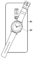
도 6a 및 도 6b는 전자 장치의 무선 충전 기능을 이용해 웨어러블 장치(602)를 무선 충전하는 사용자 시나리오의 예시이다. 도 6a 및 도 6b에 도시된 예에서는, 무선 전력 수신 장치(602)가 웨어러블 장치(602)(예: 스마트 워치, 무선 이어폰, 무선 헤드셋)인 것으로 도시하였으나, 무선 전력 수신 장치(602)는 상대적으로 낮은 전력 (예: 5V/3.75W)을 수신하여 무선 충전 가능한 다양한 전자 장치일 수 있다.6A and 6B are examples of user scenarios for wirelessly charging the
도 6a를 참조하면, 다양한 실시예에 따른 전자 장치(601)(예: 도 1의 전자 장치(101))는 사용자 입력에 기반하여 무선 전력 Tx mode를 활성화할 수 있고, 무선 전력 Tx mode가 활성화되면 배터리(예: 도 5의 배터리(510))의 전원을 이용하여 웨어러블 장치(602)에게 무선으로 전력을 공급할 수 있다. 예를 들면, 사용자 입력은 디스플레이(예: 도 1의 표시 장치(160))를 통한 사용자의 터치 입력, 또는 하우징(예: 도 4의 하우징(405)) 외부에 형성된 물리 버튼의 조작을 포함할 수 있다.Referring to FIG. 6A, the
도 6b를 참조하면, 다양한 실시예에 따른 전자 장치(601)는 유선 전력 공급 장치(603)(예컨대 travel adapter)가 연결된 경우 유선 전력 공급 장치(603)로부터 전력을 수신하여 웨어러블 장치(602)에 전력을 공급함과 동시에 배터리(510)를 충전할 수 있다.Referring to FIG. 6B, the
다양한 실시예에 따르면, 전자 장치(601)는 무선 전력 Tx mode가 활성화되면, 지정된 표준(예컨대 WPC 표준)에 따라 외부 장치(602)와 인-밴드(in-band) 통신을 수행하고, 외부 장치(602)와 무선 전력 전송에 필요한 정보들을 교환할 수 있다. 예를 들면, WPC 표준에 따른 무선 충전은 ping 단계, identification & configuration 단계, 또는 power transfer 단계를 포함할 수 있다. 일 실시예에 따르면, ping 단계는 무선 전력 수신 장치(예: 도 6a의 웨어러블 장치(602))가 무선 충전 패드 위에 놓여있는지 여부를 판단하는 단계이고, 예를 들면, 전자 장치(601)가 외부 장치(602) (예: 도 6a의 웨어러블 장치(602))와 근접하였는지 여부를 판단하는 단계일 수 있다. 일 실시예에 따르면, identification & configuration 단계는 무선 전력 송신 장치(예: 도 6a의 전자 장치(601))와 무선 전력 수신 장치(예: 도 6a의 웨어러블 장치(602)) 간의 통신을 통해 전력 전송량을 설정하는 단계이고, 예를 들면, 전자 장치(601)가 외부 장치(602)에게 전송할 지정된 무선 전력을 결정하는 단계일 수 있다. 일 실시예에 따르면, power transfer 단계는 상기 지정된 무선 전력을 전송하는 단계이고, 예를 들면, 전자 장치(601)가 외부 장치(602)에게 상기 지정된 무선 전력을 전송하는 단계일 수 있다. 일 실시예에 따르면, 전자 장치(601)는 무선 전력 Tx mode가 활성화되면 상기 3개의 단계를 수행하여 무선 전력을 전송하고, 무선 전력 Tx mode가 비활성화되면 상기 3개의 단계를 수행하지 않을 수 있다. 일 실시예에 따르면, 전자 장치(601)는 Tx mode가 비활성화되면 디스플레이(160)를 통해 무선 전력 Tx mode가 비활성화되었음을 알리는 알림을 표시할 수 있다.According to various embodiments, when the wireless power Tx mode is activated, the
일 실시예에 따르면, 전자 장치(601)는 무선 전력 Tx mode가 활성화되면, 지정된 표준(예컨대 WPC 표준)에 따라 외부 장치(602)를 확인하고, 확인된 외부 장치(602)에 대응하는 지정된 전력을 결정할 수 있다. 예를 들면, 전자 장치(601)는 외부 장치(602)가 웨어러블 장치(602)인 것을 확인하고, 웨어러블 장치(602)에 대응하는 제 2 지정된 전력(예: 5V/3.75W)을 결정할 수 있다. 일 실시예에 따르면, 전자 장치(601)는 유선 전력 공급 장치(603)로부터 제공된 외부 전원을 이용하여 지정된 전력의 무선 전력을 전송할 수 있다. 예를 들면, 전자 장치(601)는 송신 장치 파라미터를 FSK 모듈레이션하고, 송신 장치 파라미터를 FSK 모듈레이션한 신호를 전력 신호와 함께 외부 장치(602)에게 전송할 수 있다. 전자 장치(601)는 외부 장치(602)로부터 송신 장치 파라미터를 FSK 모듈레이션한 신호에 대한 응답을 수신하고, 수신된 응답에 적어도 기반하여 외부 장치(602)에 대응하는 지정된 전력을 결정할 수 있다. 전자 장치(601)는 외부 장치(602)에게 상기 지정된 전력으로 무선 전력을 전송할 수 있다.According to an embodiment, when the wireless power Tx mode is activated, the
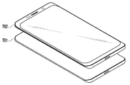
도 7a 및 도 7b는 전자 장치의 무선 충전 기능을 이용해 외부 전자 장치를 무선 충전하는 사용자 시나리오의 예시이다. 도 7a 및 도 7b에 도시된 예에서는, 무선 전력 수신 장치(702)가 전자 장치(스마트폰)(702)인 것으로 도시하였으나, 무선 전력 수신 장치(702)는 상대적으로 높은 전력(예: 7.5V/7.5W)을 수신 하여 무선 충전 가능한 다양한 전자 장치일 수 있다.7A and 7B are examples of user scenarios for wirelessly charging an external electronic device using the wireless charging function of the electronic device. 7A and 7B, the wireless
도 7a를 참조하면, 다양한 실시예에 따른 전자 장치(701)(예: 도 1의 전자 장치(101))는 사용자 입력에 기반하여 무선 전력 Tx mode를 활성화할 수 있고, 무선 전력 Tx mode가 활성화되면 배터리(510)(예: 도 5의 배터리(510))의 전원을 이용하여 외부 전자 장치(702)에게 무선으로 전력을 공급할 수 있다.Referring to FIG. 7A, the
도 7b를 참조하면, 다양한 실시예에 따른 전자 장치(701)는 고속 충전을 지원하는 유선 전력 공급(예컨대, AFC, QC, 또는 PD)(9V/15W 기준)가 연결된 경우 유선 전력 공급 장치(703)로부터 전력을 수신하여 외부 전자 장치(701)에 전력을 공급함과 동시에 배터리(510)를 충전할 수 있다. 예를 들면, 전자 장치(701)는 고속 충전을 지원하는 유선 전력 공급 장치(703)가 연결된 경우에만, 유선 전력 공급 장치(703)로부터 전력을 수신하여 외부 전자 장치(702)에 무선 전력을 공급할 수 있다.Referring to FIG. 7B, the
일 실시예에 따르면, 전자 장치(701)는 무선 전력 Tx mode가 활성화되면, 지정된 표준(예컨대 WPC 표준)에 따라 외부 장치(702)를 확인하고, 확인된 외부 장치(702)에 대응하는 지정된 전력을 결정할 수 있다. 예를 들면, 전자 장치(701)는 외부 장치(702)가 스마트폰(702)인 것을 확인하고, 스마트폰(702)에 대응하는 제 1 지정된 전력(예: 7.5V/7.5W)을 결정할 수 있다. 일 실시예에 따르면, 전자 장치(701)는 유선 전력 공급 장치(603)로부터 제공된 외부 전원을 이용하여 지정된 전력의 무선 전력을 전송할 수 있다. 예를 들면, 전자 장치(701)는 송신 장치 파라미터를 FSK 모듈레이션하고, 송신 장치 파라미터를 FSK 모듈레이션한 신호를 전력 신호와 함께 외부 장치(702)에게 전송할 수 있다. 전자 장치(701)는 외부 장치(702)로부터 송신 장치 파라미터를 FSK 모듈레이션한 신호에 대한 응답을 수신하고, 수신된 응답에 적어도 기반하여 외부 장치(702)에 대응하는 지정된 전력을 결정할 수 있다. 전자 장치(701)는 외부 장치(702)에게 상기 지정된 전력으로 무선 전력을 전송할 수 있다.According to an embodiment, when the wireless power Tx mode is activated, the
도 8은 일 실시예에 따른 전자 장치의 무선 전력 회로가 Tx 모드인 경우를 설명한 블록도이다.8 is a block diagram illustrating a case where a wireless power circuit of an electronic device according to an embodiment is in a Tx mode.
도 8을 참조하면, 일 실시예에 따른 전자 장치(801)(예: 도 3의 전자 장치(301)는 코일(850)(예: 도 3의 코일(350)), 무선 충전 IC(840)(예: 도 3의 무선 충전 IC(840)), PMIC(power management IC)(820)(예: 도 3의 PMIC(320)), 배터리(830)(예: 도 3의 배터리(330)), 외부 전원(예: AFC, QC, PD, 또는 USB)(803)(예), 및/또는 제어 회로(810)(controller)(예: 도 1의 프로세서(120))를 포함할 수 있다.Referring to FIG. 8, an
일 실시예에 따르면, 무선 충전 IC(840)는 WPC 표준에 따라 외부 전자 장치(802)(예: 도 3의 제 2 전자 장치(302))와 인-밴드(in-band) 통신을 통해 무선 전력 전송에 필요한 정보들을 송수신할 수 있다. 예를 들면, 인-밴드 통신은 Tx 모드에서 무선 전력 전송 신호의 frequency 모듈레이션을 통해 데이터를 외부 전자 장치(802)에게 전송하는 것을 의미할 수 있다.According to an embodiment, the
일 실시예에 따르면, 무선 충전 IC(840)는 전력 송수신 회로(842) 및 통신 회로(841)를 포함할 수 있다.According to an embodiment, the
일 실시예에 따르면, 전력 송수신 회로(842)는 전자 장치(801)가 Tx 모드로 동작 할 때 RF power generator(inverter)로 동작할 수 있다.According to an embodiment, the power transmission /
일 실시예에 따르면, 통신 회로(841) 는 외부 전자 장치(802)와 통신하기 위하여 구성된 회로일 수 있다. 예를 들면, 통신 회로(841)는 전자 장치(801)가 Tx 모드로 동작 할 때 외부 전자 장치(802)와 통신하기 위하여 송신 장치 파라미터를 FSK 모듈레이션한 신호를 생성할 수 있다.According to an embodiment, the
다양한 실시 예에 따르면, 통신 회로(841)는 코일(850)에서 전력 전달을 위해 사용하는 주파수와 동일하거나 인접한 주파수를 이용하여 외부 전자 장치(802)의 통신 회로와 통신할 수 있다. 예를 들면, 통신 회로(841)는 송신 장치 파라미터를 FSK 모듈레이션하고, 송신 장치 파라미터를 FSK 모듈레이션한 신호를 전력 신호와 함께 전송할 수 있다. 예를 들면, 통신 회로(841)는 FSK 모듈레이션을 이용하여 전력 수신 장치(sink device)인 외부 전자 장치(802)에게 데이터를 전달할 수 있다.According to various embodiments, the
일 실시예에 따르면, 전자 장치(801)가 Tx 모드로 동작 할 때 전송하는 상기 전력 신호는 110kHz~190kHz 대역의 무선 신호일 수 있다. 일 실시예에 따르면, 통신 회로(841)는 상기 전력 신호의 대역 대비 △ 0.2%~5% 인근 대역 신호, 예컨대 104.5~199.5 kHz를 생성할 수 있다. 예를 들면, 통신 회로(841)는, FSK 모듈레이션을 수행함에 있어서, Positive 신호의 경우 전력 신호 신호 주파수 보다 높은 주파수, 예를 들어, 전력 전송 주파수가 110kHz인 경우, 110kHz 보다 높은 주파수(예: 110.7kHz) 신호가 되도록 모듈레이션할 수 있다. 다른 예로, 통신 회로(841)는, Negative 신호의 경우 전력 신호 주파수 보다 낮은 주파수, 예를 들어, 전력 전송 주파수가 110kHz인 경우, 110kHz 보다 낮은 주파수(예. 109.6kHz) 신호가 되도록 모듈레이션할 수 있다.According to an embodiment, when the
일 실시예에 따르면, 전자 장치(801)가 Tx 모드로 동작 할 때 통신 회로(841)는 FSK 모듈레이션 뎁스(modulation depth)를 계산하기 위한 스케일링 인자(scaling factor)를 포함하는 뎁스(depth)를 0으로 설정하고, 상기 전력 신호의 대역 대비 △ 0.3% 인근 대역 신호을 생성할 수 있다.According to an embodiment, when the
일 실시예에 따르면, 전자 장치(801)가 Tx 모드로 동작 할 때 통신 회로(841)는 FSK 모듈레이션 뎁스(modulation depth)를 계산하기 위한 스케일링 인자(scaling factor)를 포함하는 뎁스(depth)를 3으로 설정하고, 상기 전력 신호의 대역 대비 △ 3.2% 인근 대역 신호을 생성할 수 있다.According to an embodiment, when the
일 실시예에 따르면, 전자 장치(801)가 Tx 모드로 동작 할 때 전송하는 송신 장치 파라미터는 capacity packet으로서, 전자 장치(801)의 식별 정보, 배터리(830) 정보, 전자 장치(801)에 연결된 TA(travel adapter) 정보, 상기 배터리(830) 및 TA 정보를 기반하여 공급할 수 있는 전력 정보, 또는 전송 모드(전압, 전류, 전력) 정보를 포함할 수 있다.According to an embodiment, when the
도 9는 일 실시예에 따른 전자 장치의 무선 전력 회로가 Rx 모드인 경우를 설명한 블록도이다. 도 9에 도시된 전자 장치는 도 8에 도시된 전자 장치와 동일 또는 유사한 구성일 수 있다. 도 9에서 도 8과 실질적으로 동일한 구성요소는 동일한 도면부호를 표시하였고, 이하에서는 무선 전력 회로가 Rx 모드인 경우의 동작만을 설명한다.9 is a block diagram illustrating a case where a wireless power circuit of an electronic device according to an embodiment is in an Rx mode. The electronic device illustrated in FIG. 9 may have the same or similar configuration to the electronic device illustrated in FIG. 8. In FIG. 9, substantially the same components as those in FIG. 8 are denoted by the same reference numerals, and the following describes only the operation when the wireless power circuit is in the Rx mode.
도 9를 참조하면, 무선 충전 IC(840)는 WPC 표준에 따라 외부 전자 장치(802)(예: 도 3의 제 2 전자 장치(302))와 인-밴드(in-band) 통신을 통해 무선 전력 전송에 필요한 정보들을 전송할 수 있다. 예를 들면, 인-밴드 통신은 Rx 모드에서 amplitude 모듈레이션을 통해 데이터를 외부 전자 장치(802)에게 전송하는 것을 의미할 수 있다.Referring to FIG. 9, the
일 실시예에 따르면, 전력 송수신 회로(842)는 전자 장치가 Rx 모드로 동작 할 때 rectifier로 동작할 수 있다.According to an embodiment, the power transmission /
일 실시예에 따르면, 통신 회로(841)는 외부 전자 장치(802)와 통신하기 위하여 구성된 회로일 수 있다. 예를 들면, 통신 회로(841)는 전자 장치(801)가 Rx 모드로 동작 할 때 외부 전자 장치(802)와 통신하기 위하여 수신 장치 파라미터를 ASK(amplitude shift keying) 모듈레이션한 신호를 생성할 수 있다.According to an embodiment, the
다양한 실시 예에 따르면, 통신 회로(841)는 코일(850)에서 전력 수신을 위해 사용하는 주파수와 동일하거나 인접한 주파수를 이용하여 외부 전자 장치(802)의 통신 회로와 통신할 수 있다. 통신 회로(841)는 수신 장치 파라미터를 ASK 모듈레이션하고, 수신 장치 파라미터를 ASK 모듈레이션한 신호를 전송할 수 있다. 예를 들면, 통신 회로(841)는 ASK 모듈레이션을 이용하여 전력 송신 장치(source device)인 외부 전자 장치(802)에게 데이터를 전달할 수 있다.According to various embodiments, the
일 실시예에 따르면, 통신 회로(841)는 전자 장치(801)가 Rx 모드로 동작 할 때 수신되는 전력 신호의 전압 대비 △ 1~30% 의 전압 변화를 갖는 신호를 생성할 수 있다. 예를 들면, 통신 회로(841)는 전자 장치가 Rx 모드로 동작 할 때 코일에 연결된 회로를 제어하여, 전력 송신 장치(source device)인 외부 전자 장치(802)에서 로드(load)가 변함을 인식할 수 있도록 수신 장치 파라미터를 ASK 모듈레이션할 수 있다.According to an embodiment, the
일 실시예에 따르면, 전자 장치(801)가 Rx 모드로 동작 할 때 전송하는 수신 장치 파라미터는 충전 모드(전압, 전류, 전력) 변경 요청 정보, 전자 장치(801)의 식별 정보, 수신 가능한 전력 정보, 수신 전력 상태 정보, 또는 배터리(830) 정보를 포함할 수 있다.According to an embodiment, the receiving device parameters transmitted when the
본 발명의 다양한 실시예에 따른 전자 장치(예: 도 8의 전자 장치(801))의 구동 방법은, 무선 전력 회로(예: 도 8의 무선 충전 IC(840))가 Tx 모드인 경우, 상기 무선 전력 회로(840)를 이용하여 무선 전력 신호를 코일(예: 도 8의 코일(850)) 통하여 전송 및 통신 회로(예: 도 8의 통신 회로(841))를 이용하여 송신 장치 파라미터를 FSK(frequency shift keying) 모듈레이션한 신호를 상기 코일(850)을 통해 외부 전자 장치(예: 도 8의 외부 전자 장치(802))로 전송하는 동작, 및 상기 무선 전력 회로(840)가 Rx 모드인 경우, 상기 무선 전력 회로(840)를 이용하여 무선 전력을 수신하여 배터리(830)를 충전 및 상기 통신 회로(841)를 이용하여 수신 장치 파라미터를 ASK(amplitude shift keying) 모듈레이션한 신호를 상기 코일(850)을 통해 외부 전자 장치(802)로 전송하는 동작을 포함할 수 있다. 상기 무선 전력 신호는 110kHz~190kHz 대역의 무선 신호일 수 있다. 상기 FSK 모듈레이션하는 동작은 상기 통신 회로(841)를 이용하여 상기 송신 장치 파라미터를 상기 무선 전력 신호의 대역 대비 △0.2%~5% 인근 대역의 신호로 FSK 모듈레이션하는 동작을 포함할 수 있다. 상기 FSK 모듈레이션하는 동작은 스케일링 인자(scaling factor)를 포함하는 뎁스(depth)를 0으로 설정하는 동작, 및 상기 송신 장치 파라미터를 상기 무선 전력 신호의 대역 대비 △0.3% 인근 대역의 신호로 FSK 모듈레이션하는 동작을 포함할 수 있다. 상기 FSK 모듈레이션하는 동작은 스케일링 인자(scaling factor)를 포함하는 뎁스(depth)를 3으로 설정하는 동작, 및 상기 송신 장치 파라미터를 상기 무선 전력 신호의 대역 대비 △3.2% 인근 대역의 신호로 FSK 모듈레이션하는 동작을 포함할 수 있다. 상기 송신 장치 파라미터는 상기 전자 장치(801)의 식별 정보, 상기 배터리(830) 정보, 상기 전자 장치(801)에 연결된 TA(travel adapter) 정보, 상기 배터리(830) 및 상기 TA 정보를 기반하여 공급할 수 있는 전력 정보, 또는 전송 모드 정보 중에서 적어도 하나를 포함할 수 있다. 상기 무선 전력 회로(840)가 Tx 모드인 경우, 상기 송신 장치 파라미터를 모듈레이션한 신호에 대한 응답 신호를 상기 외부 전자 장치(802)로부터 수신하는 동작, 및 상기 응답 신호에 기반하여 결정된 지정된 무선 전력 신호를 상기 코일(850) 통하여 전송하는 동작을 더 포함할 수 있다. 상기 ASK 모듈레이션하는 동작은 상기 통신 회로(841)를 이용하여 상기 수신 장치 파라미터를 상기 수신된 무선 전력의 전압 대비 △1%~30% 의 전압 변화를 갖는 신호로 ASK 모듈레이션하는 동작을 포함할 수 있다.A method of driving an electronic device (for example, the
도 10은 일 실시예에 따른 전자 장치의 동작을 나타낸 흐름도이다.10 is a flowchart illustrating an operation of an electronic device according to an embodiment.
동작 1001 및 동작 1002에서, 일 실시예에 따른 전자 장치(예: 도 8의 전자 장치(801))는, 무선 충전 모드를 확인하고, 전자 장치(801)가 Tx 모드인지 여부를 확인할 수 있다. 일 실시예에 따르면, 전자 장치(801)는 Tx 모드인 경우(예: 동작 1002에서 YES인 경우) 동작 1003을 수행하고, RX 모드인 경우(예: 동작 1002에서 NO인 경우) 동작 1004를 수행할 수 있다.In
동작 1003에서, 일 실시예에 따른 전자 장치(801)는, Tx 모드인 경우에 송신 장치 파라미터로서 capacity 데이터를 생성할 수 있다. 예를 들면, 송신 장치 파라미터는 capacity packet으로서, 전자 장치(801)의 식별 정보, 배터리(예: 도 8의 배터리(830)) 정보, 전자 장치(801)에 연결된 TA(travel adapter) 정보, 상기 배터리(830) 및 TA 정보를 기반하여 공급할 수 있는 전력 정보, 또는 전송 모드(전압, 전류, 전력) 정보를 포함할 수 있다.In
동작 1005에서, 일 실시예에 따른 전자 장치(801)는, 통신 회로(841)를 이용하여 송신 장치 파라미터를 FSK(frequency shift keying) 모듈레이션한 신호를 상기 코일을 통해 외부 전자 장치(801)로 전송할 수 있다. 예를 들면, 전자 장치(801)는 상기 통신 회로(841)를 이용하여 상기 송신 장치 파라미터를 무선 전력 신호의 대역 대비 △0.2%~5% 인근 대역의 신호로 FSK 모듈레이션할 수 있다.In
동작 1004에서, 일 실시예에 따른 전자 장치(801)는, Rx 모드인 경우에 수신 장치 파라미터로서, 충전 모드(전압, 전류, 전력) 변경 요청 정보, 전자 장치(801)의 식별 정보, 수신 가능한 전력 정보, 수신 전력 상태 정보, 또는 배터리(830) 정보를 생성할 수 있다.In
동작 1006에서, 일 실시예에 따른 전자 장치(801)는, 통신 회로(841)를 이용하여 수신 장치 파라미터를 ASK(amplitude shift keying) 모듈레이션한 신호를 코일을 통해 외부 전자 장치(801)로 전송할 수 있다. 예를 들면, 전자 장치(801)는 통신 회로(841)를 이용하여 상기 수신 장치 파라미터를 수신된 무선 전력의 전압 대비 △1%~30% 의 전압 변화를 갖는 신호로 ASK 모듈레이션할 수 있다. 예를 들면, 통신 회로(841)는 전자 장치가 Rx 모드로 동작 할 때 코일에 연결된 회로를 제어하여, 전력 송신 장치(source device)인 외부 전자 장치(802)에서 로드(load)가 변함을 인식할 수 있도록 수신 장치 파라미터를 ASK 모듈레이션할 수 있다.In
본 문서에 개시된 다양한 실시 예들에 따른 전자 장치는 다양한 형태의 장치가 될 수 있다. 전자 장치는, 예를 들면, 휴대용 통신 장치 (예: 스마트폰), 컴퓨터 장치, 휴대용 멀티미디어 장치, 휴대용 의료 기기, 카메라, 웨어러블 장치, 또는 가전 장치를 포함할 수 있다. 본 문서의 실시 예에 따른 전자 장치는 전술한 기기들에 한정되지 않는다.An electronic device according to various embodiments disclosed in this document may be a device of various types. The electronic device may include, for example, a portable communication device (eg, a smart phone), a computer device, a portable multimedia device, a portable medical device, a camera, a wearable device, or a home appliance device. The electronic device according to the exemplary embodiment of the present document is not limited to the aforementioned devices.
본 문서의 다양한 실시 예들 및 이에 사용된 용어들은 본 문서에 기재된 기술적 특징들을 특정한 실시 예들로 한정하려는 것이 아니며, 해당 실시 예의 다양한 변경, 균등물, 또는 대체물을 포함하는 것으로 이해되어야 한다. 도면의 설명과 관련하여, 유사한 또는 관련된 구성요소에 대해서는 유사한 참조 부호가 사용될 수 있다. 아이템에 대응하는 명사의 단수 형은 관련된 문맥상 명백하게 다르게 지시하지 않는 한, 상기 아이템 한 개 또는 복수 개를 포함할 수 있다. 본 문서에서, "A 또는 B", "A 및 B 중 적어도 하나",“A 또는 B 중 적어도 하나,”"A, B 또는 C," "A, B 및 C 중 적어도 하나,”및 “A, B, 또는 C 중 적어도 하나"와 같은 문구들 각각은 그 문구들 중 해당하는 문구에 함께 나열된 항목들 중 어느 하나, 또는 그들의 모든 가능한 조합을 포함할 수 있다. "제 1", "제 2", 또는 "첫째" 또는 "둘째"와 같은 용어들은 단순히 해당 구성요소를 다른 해당 구성요소와 구분하기 위해 사용될 수 있으며, 해당 구성요소들을 다른 측면(예: 중요성 또는 순서)에서 한정하지 않는다. 어떤(예: 제 1) 구성요소가 다른(예: 제 2) 구성요소에, “기능적으로” 또는 “통신적으로”라는 용어와 함께 또는 이런 용어 없이, “커플드” 또는 “커넥티드”라고 언급된 경우, 그것은 상기 어떤 구성요소가 상기 다른 구성요소에 직접적으로(예: 유선으로), 무선으로, 또는 제 3 구성요소를 통하여 연결될 수 있다는 것을 의미한다.It should be understood that various embodiments of the document and terms used therein are not intended to limit the technical features described in this document to specific embodiments, and include various modifications, equivalents, or substitutes of the corresponding embodiments. In connection with the description of the drawings, similar reference numerals may be used for similar or related components. The singular form of a noun corresponding to an item may include one or more of the items, unless the context clearly indicates otherwise. In this document, “A or B”, “at least one of A and B”, “at least one of A or B,” “A, B or C,” “at least one of A, B and C,” and “A Each of the phrases such as "at least one of,, B, or C" may include any one of the items listed together in the corresponding phrase of the phrases, or all possible combinations thereof. Terms such as “first”, “second”, or “first” or “second” can be used to simply distinguish a component from other components, and to separate components from other aspects (eg, importance or Order). Any (eg, first) component is “coupled” or “connected” to another (eg, second) component, with or without the term “functionally” or “communically” When mentioned, it means that any of the above components can be connected directly to the other components (eg, by wire), wirelessly, or through a third component.
본 문서에서 사용된 용어 "모듈"은 하드웨어, 소프트웨어 또는 펌웨어로 구현된 유닛을 포함할 수 있으며, 예를 들면, 로직, 논리 블록, 부품, 또는 회로 등의 용어와 상호 호환적으로 사용될 수 있다. 모듈은, 일체로 구성된 부품 또는 하나 또는 그 이상의 기능을 수행하는, 상기 부품의 최소 단위 또는 그 일부가 될 수 있다. 예를 들면, 일 실시 예에 따르면, 모듈은 ASIC(application-specific integrated circuit)의 형태로 구현될 수 있다. The term "module" as used herein may include a unit implemented in hardware, software, or firmware, and may be used interchangeably with terms such as logic, logic blocks, components, or circuits. The module may be an integrally configured component or a minimum unit of the component or a part thereof performing one or more functions. For example, according to an embodiment, the module may be implemented in the form of an application-specific integrated circuit (ASIC).
본 문서의 다양한 실시 예들은 기기(machine)(예: 전자 장치(101)) 의해 읽을 수 있는 저장 매체(storage medium)(예: 내장 메모리(136) 또는 외장 메모리(138))에 저장된 하나 이상의 명령어들을 포함하는 소프트웨어(예: 프로그램(140))로서 구현될 수 있다. 예를 들면, 기기(예: 전자 장치(101))의 프로세서(예: 프로세서(120))는, 저장 매체로부터 저장된 하나 이상의 명령어들 중 적어도 하나의 명령을 호출하고, 그것을 실행할 수 있다. 이것은 기기가 상기 호출된 적어도 하나의 명령어에 따라 적어도 하나의 기능을 수행하도록 운영되는 것을 가능하게 한다. 상기 하나 이상의 명령어들은 컴파일러에 의해 생성된 코드 또는 인터프리터에 의해 실행될 수 있는 코드를 포함할 수 있다. 기기로 읽을 수 있는 저장매체 는, 비일시적(non-transitory) 저장매체의 형태로 제공될 수 있다. 여기서, ‘비일시적’은 저장매체가 실재(tangible)하는 장치이고, 신호(signal)(예: 전자기파)를 포함하지 않는다는 것을 의미할 뿐이며, 이 용어는 데이터가 저장매체에 반영구적으로 저장되는 경우와 임시적으로 저장되는 경우를 구분하지 않는다.Various embodiments of the present disclosure may include one or more instructions stored in a storage medium (eg,
일 실시 예에 따르면, 본 문서에 개시된 다양한 실시 예들에 따른 방법은 컴퓨터 프로그램 제품(computer program product)에 포함되어 제공될 수 있다. 컴퓨터 프로그램 제품은 상품으로서 판매자 및 구매자 간에 거래될 수 있다. 컴퓨터 프로그램 제품은 기기로 읽을 수 있는 저장 매체(예: compact disc read only memory (CD-ROM))의 형태로 배포되거나, 또는 어플리케이션 스토어(예: 플레이 스토어TM)를 통해 또는 두개의 사용자 장치들(예: 스마트폰들) 간에 직접, 온라인으로 배포(예: 다운로드 또는 업로드)될 수 있다. 온라인 배포의 경우에, 컴퓨터 프로그램 제품의 적어도 일부는 제조사의 서버, 어플리케이션 스토어의 서버, 또는 중계 서버의 메모리와 같은 기기로 읽을 수 있는 저장 매체에 적어도 일시 저장되거나, 임시적으로 생성될 수 있다.According to one embodiment, a method according to various embodiments disclosed in this document may be provided as being included in a computer program product. Computer program products are commodities that can be traded between sellers and buyers. The computer program product is distributed in the form of a device-readable storage medium (eg compact disc read only memory (CD-ROM)), or through an application store (eg Play Store TM ) or two user devices ( It can be distributed (eg, downloaded or uploaded) directly or online between smartphones). In the case of online distribution, at least a portion of the computer program product may be temporarily stored at least temporarily in a storage medium readable by a device such as a memory of a manufacturer's server, an application store's server, or a relay server, or may be temporarily generated.
다양한 실시 예들에 따르면, 상기 기술한 구성요소들의 각각의 구성요소(예: 모듈 또는 프로그램)는 단수 또는 복수의 개체를 포함할 수 있다. 다양한 실시 예들에 따르면, 전술한 해당 구성요소들 중 하나 이상의 구성요소들 또는 동작들이 생략되거나, 또는 하나 이상의 다른 구성요소들 또는 동작들이 추가될 수 있다. 대체적으로 또는 추가적으로, 복수의 구성요소들(예: 모듈 또는 프로그램)은 하나의 구성요소로 통합될 수 있다. 이런 경우, 통합된 구성요소는 상기 복수의 구성요소들 각각의 구성요소의 하나 이상의 기능들을 상기 통합 이전에 상기 복수의 구성요소들 중 해당 구성요소에 의해 수행되는 것과 동일 또는 유사하게 수행할 수 있다. 다양한 실시 예들에 따르면, 모듈, 프로그램 또는 다른 구성요소에 의해 수행되는 동작들은 순차적으로, 병렬적으로, 반복적으로, 또는 휴리스틱하게 실행되거나, 상기 동작들 중 하나 이상이 다른 순서로 실행되거나, 생략되거나, 또는 하나 이상의 다른 동작들이 추가될 수 있다.According to various embodiments, each component (eg, module or program) of the above-described components may include a singular or a plurality of entities. According to various embodiments, one or more components or operations among the above-described corresponding components may be omitted, or one or more other components or operations may be added. Alternatively or additionally, a plurality of components (eg, modules or programs) may be integrated into one component. In this case, the integrated component may perform one or more functions of each component of the plurality of components the same or similar to that performed by the corresponding component among the plurality of components prior to the integration. . According to various embodiments, operations performed by a module, program, or other component may be executed sequentially, in parallel, repeatedly, or heuristically, or one or more of the operations may be executed in a different order, omitted, or the like. , Or one or more other actions can be added.
100: 전자 장치
120: 프로세서
130: 메모리
160: 표시 장치100: electronic device
120: processor
130: memory
160: display device
Claims (17)
배터리;
상기 배터리의 충전 상태를 제어하는 PMIC(power management integrated circuit);
코일;
상기 코일과 전기적 연결된 무선 전력 회로;
상기 코일과 전기적 연결된 통신 회로; 및
프로세서를 포함하고, 상기 프로세서는,
상기 무선 전력 회로가 Tx 모드인 경우, 상기 무선 전력 회로를 이용하여 무선 전력 신호를 상기 코일 통하여 전송 및 상기 통신 회로를 이용하여 송신 장치 파라미터를 FSK(frequency shift keying) 모듈레이션한 신호를 상기 코일을 통해 외부 전자 장치로 전송하고,
상기 무선 전력 회로가 Rx 모드인 경우, 상기 무선 전력 회로를 이용하여 무선 전력을 수신하여 배터리를 충전 및 상기 통신 회로를 이용하여 수신 장치 파라미터를 ASK(amplitude shift keying) 모듈레이션한 신호를 상기 코일을 통해 외부 전자 장치로 전송하도록 설정된, 전자 장치.In the electronic device,
battery;
A power management integrated circuit (PMIC) that controls the state of charge of the battery;
coil;
A wireless power circuit electrically connected to the coil;
A communication circuit electrically connected to the coil; And
It includes a processor, the processor,
When the wireless power circuit is in the Tx mode, a wireless power signal is transmitted through the coil using the wireless power circuit, and a frequency shift keying (FSK) modulated signal is transmitted through the coil using the communication circuit. Transmitted to an external electronic device,
When the wireless power circuit is in the Rx mode, the wireless power circuit is used to receive wireless power to charge the battery, and the ASK (amplitude shift keying) modulated signal is received through the coil to receive the device parameters using the communication circuit. An electronic device set to transmit to an external electronic device.
상기 무선 전력 신호는 110kHz~190kHz 대역의 무선 신호인, 전자 장치.According to claim 1,
The wireless power signal is an electronic device, which is a wireless signal in the 110 kHz to 190 kHz band.
상기 프로세서는
상기 무선 전력 회로가 상기 Tx 모드인 경우, 상기 통신 회로를 이용하여 상기 송신 장치 파라미터를 상기 무선 전력 신호의 대역 대비 △0.2%~5% 인근 대역의 신호로 FSK 모듈레이션하도록 설정된, 전자 장치.According to claim 1,
The processor
When the wireless power circuit is in the Tx mode, the electronic device is configured to FSK modulate the transmission device parameter to a signal of a band in the vicinity of Δ0.2% to 5% of the band of the wireless power signal using the communication circuit.
상기 프로세서는
상기 무선 전력 회로가 상기 Tx 모드인 경우, 스케일링 인자(scaling factor)를 포함하는 뎁스(depth)를 0으로 설정하고,
상기 송신 장치 파라미터를 상기 무선 전력 신호의 대역 대비 △0.3% 인근 대역의 신호로 FSK 모듈레이션하도록 설정된, 전자 장치.The method of claim 3,
The processor
When the wireless power circuit is in the Tx mode, a depth including a scaling factor is set to 0,
An electronic device configured to FSK modulate the transmission device parameter to a signal of a band adjacent to Δ0.3% of the band of the wireless power signal.
상기 프로세서는
상기 무선 전력 회로가 상기 Tx 모드인 경우, 스케일링 인자(scaling factor)를 포함하는 뎁스(depth)를 3으로 설정하고,
상기 송신 장치 파라미터를 상기 무선 전력 신호의 대역 대비 △3.2% 인근 대역의 신호로 FSK 모듈레이션하도록 설정된, 전자 장치.The method of claim 3,
The processor
When the wireless power circuit is in the Tx mode, a depth including a scaling factor is set to 3,
An electronic device configured to FSK modulate the transmission device parameter with a signal of a band adjacent to Δ3.2% of the band of the wireless power signal.
상기 송신 장치 파라미터는
상기 전자 장치의 식별 정보, 상기 배터리 정보, 상기 전자 장치에 연결된 TA(travel adapter) 정보, 상기 배터리 및 상기 TA 정보를 기반하여 공급할 수 있는 전력 정보, 또는 전송 모드 정보 중에서 적어도 하나를 포함하는, 전자 장치.According to claim 1,
The transmission device parameters
The electronic device includes at least one of identification information of the electronic device, the battery information, travel adapter (TA) information connected to the electronic device, power information that can be supplied based on the battery and the TA information, or transmission mode information. Device.
상기 프로세서는
상기 무선 전력 회로가 Tx 모드인 경우, 상기 송신 장치 파라미터를 모듈레이션한 신호에 대한 응답 신호를 상기 외부 전자 장치로부터 수신하고,
상기 응답 신호에 기반하여 결정된 지정된 무선 전력 신호를 상기 코일 통하여 전송하도록 설정된, 전자 장치.The method of claim 6,
The processor
When the wireless power circuit is in Tx mode, a response signal to a signal modulating the transmission device parameter is received from the external electronic device,
An electronic device configured to transmit a designated wireless power signal determined based on the response signal through the coil.
상기 프로세서는
상기 무선 전력 회로가 상기 Rx 모드인 경우, 상기 통신 회로를 이용하여 상기 수신 장치 파라미터를 상기 수신된 무선 전력의 전압 대비 △1%~30% 의 전압 변화를 갖는 신호로 ASK 모듈레이션 하도록 설정된, 전자 장치.According to claim 1,
The processor
When the wireless power circuit is in the Rx mode, an electronic device configured to ASK modulate the receiving device parameter to a signal having a voltage change of Δ1% to 30% compared to the voltage of the received wireless power using the communication circuit. .
상기 수신 장치 파라미터는
충전 모드(전압, 전류, 전력) 변경 요청 정보, 상기 전자 장치의 식별 정보, 수신 가능한 전력 정보, 수신 전력 상태 정보, 또는 상기 배터리 정보 중에서 적어도 하나를 포함하는, 전자 장치.According to claim 1,
The receiving device parameters
An electronic device comprising at least one of charging mode (voltage, current, power) change request information, identification information of the electronic device, receiveable power information, received power state information, or the battery information.
무선 전력 회로가 Tx 모드인 경우, 상기 무선 전력 회로를 이용하여 무선 전력 신호를 코일 통하여 전송 및 통신 회로를 이용하여 송신 장치 파라미터를 FSK(frequency shift keying) 모듈레이션한 신호를 상기 코일을 통해 외부 전자 장치로 전송하는 동작, 및
상기 무선 전력 회로가 Rx 모드인 경우, 상기 무선 전력 회로를 이용하여 무선 전력을 수신하여 배터리를 충전 및 상기 통신 회로를 이용하여 수신 장치 파라미터를 ASK(amplitude shift keying) 모듈레이션한 신호를 상기 코일을 통해 외부 전자 장치로 전송하는 동작을 포함하는, 방법.In the driving method of the electronic device,
When the wireless power circuit is in the Tx mode, a wireless power signal is transmitted through the coil using the wireless power circuit and a frequency shift keying (FSK) modulated signal is transmitted through the coil to the external electronic device through the coil. Transfer to, and
When the wireless power circuit is in the Rx mode, the wireless power circuit is used to receive wireless power to charge the battery, and the ASK (amplitude shift keying) modulated signal is received through the coil to receive the device parameters using the communication circuit. And transmitting to an external electronic device.
상기 무선 전력 신호는 110kHz~190kHz 대역의 무선 신호인, 방법.The method of claim 10,
The wireless power signal is a radio signal in the 110kHz ~ 190kHz band, method.
상기 FSK 모듈레이션하는 동작은
상기 통신 회로를 이용하여 상기 송신 장치 파라미터를 상기 무선 전력 신호의 대역 대비 △0.2%~5% 인근 대역의 신호로 FSK 모듈레이션하는 동작을 포함하는, 방법.The method of claim 10,
The FSK modulation operation
And using the communication circuit to modulate the transmission device parameter into a signal in a band of Δ0.2% to 5% adjacent to a band of the wireless power signal in a band.
상기 FSK 모듈레이션하는 동작은
스케일링 인자(scaling factor)를 포함하는 뎁스(depth)를 0으로 설정하는 동작, 및
상기 송신 장치 파라미터를 상기 무선 전력 신호의 대역 대비 △0.3% 인근 대역의 신호로 FSK 모듈레이션하는 동작을 포함하는, 방법.The method of claim 12,
The FSK modulation operation
Setting a depth including a scaling factor to 0, and
And FSK modulating the transmission device parameter to a signal in a band adjacent to Δ0.3% of the band of the wireless power signal.
상기 FSK 모듈레이션하는 동작은
스케일링 인자(scaling factor)를 포함하는 뎁스(depth)를 3으로 설정하는 동작, 및
상기 송신 장치 파라미터를 상기 무선 전력 신호의 대역 대비 △3.2% 인근 대역의 신호로 FSK 모듈레이션하는 동작을 포함하는, 방법.The method of claim 12,
The FSK modulation operation
Setting a depth including a scaling factor to 3, and
And FSK modulating the transmission device parameter with a signal in a band adjacent to Δ3.2% of the band of the wireless power signal.
상기 송신 장치 파라미터는
상기 전자 장치의 식별 정보, 상기 배터리 정보, 상기 전자 장치에 연결된 TA(travel adapter) 정보, 상기 배터리 및 상기 TA 정보를 기반하여 공급할 수 있는 전력 정보, 또는 전송 모드 정보 중에서 적어도 하나를 포함하는, 방법.The method of claim 10,
The transmission device parameters
And at least one of identification information of the electronic device, the battery information, travel adapter (TA) information connected to the electronic device, power information that can be supplied based on the battery and the TA information, or transmission mode information. .
상기 무선 전력 회로가 Tx 모드인 경우, 상기 송신 장치 파라미터를 모듈레이션한 신호에 대한 응답 신호를 상기 외부 전자 장치로부터 수신하는 동작, 및
상기 응답 신호에 기반하여 결정된 지정된 무선 전력 신호를 상기 코일 통하여 전송하는 동작을 더 포함하는, 방법.The method of claim 15,
When the wireless power circuit is in the Tx mode, receiving a response signal to the signal modulating the transmission device parameter from the external electronic device, and
And transmitting the designated wireless power signal determined based on the response signal through the coil.
상기 ASK 모듈레이션하는 동작은
상기 통신 회로를 이용하여 상기 수신 장치 파라미터를 상기 수신된 무선 전력의 전압 대비 △1%~30% 의 전압 변화를 갖는 신호로 ASK 모듈레이션하는 동작을 포함하는, 방법.The method of claim 10,
The ASK modulation operation
And using the communication circuit to modulate the receiving device parameter into a signal having a voltage change of Δ1% to 30% compared to the voltage of the received wireless power.
Priority Applications (5)
| Application Number | Priority Date | Filing Date | Title |
|---|---|---|---|
| KR1020180122641A KR102647156B1 (en) | 2018-10-15 | 2018-10-15 | Electronic device and method for wire and wireless charging in electronic device |
| PCT/KR2019/013500 WO2020080790A1 (en) | 2018-10-15 | 2019-10-15 | Electronic device and method for wired and wireless charging in electronic device |
| EP19874062.3A EP3850726A4 (en) | 2018-10-15 | 2019-10-15 | Electronic device and method for wired and wireless charging in electronic device |
| US16/653,443 US11355950B2 (en) | 2018-10-15 | 2019-10-15 | Electronic device and method for wired and wireless charging in electronic device |
| US17/745,221 US11658703B2 (en) | 2018-10-15 | 2022-05-16 | Electronic device and method for wired and wireless charging in electronic device |
Applications Claiming Priority (1)
| Application Number | Priority Date | Filing Date | Title |
|---|---|---|---|
| KR1020180122641A KR102647156B1 (en) | 2018-10-15 | 2018-10-15 | Electronic device and method for wire and wireless charging in electronic device |
Publications (2)
| Publication Number | Publication Date |
|---|---|
| KR20200042268A true KR20200042268A (en) | 2020-04-23 |
| KR102647156B1 KR102647156B1 (en) | 2024-03-14 |
Family
ID=70160494
Family Applications (1)
| Application Number | Title | Priority Date | Filing Date |
|---|---|---|---|
| KR1020180122641A KR102647156B1 (en) | 2018-10-15 | 2018-10-15 | Electronic device and method for wire and wireless charging in electronic device |
Country Status (4)
| Country | Link |
|---|---|
| US (2) | US11355950B2 (en) |
| EP (1) | EP3850726A4 (en) |
| KR (1) | KR102647156B1 (en) |
| WO (1) | WO2020080790A1 (en) |
Cited By (2)
| Publication number | Priority date | Publication date | Assignee | Title |
|---|---|---|---|---|
| CN112769252A (en) * | 2020-12-31 | 2021-05-07 | 华乙半导体(深圳)有限公司 | Wireless charging device and method and central processing unit |
| WO2022108333A1 (en) * | 2020-11-17 | 2022-05-27 | 엘지전자 주식회사 | Fast fsk decoding method and device in wireless power transmission system |
Families Citing this family (6)
| Publication number | Priority date | Publication date | Assignee | Title |
|---|---|---|---|---|
| US11329696B2 (en) | 2020-06-24 | 2022-05-10 | Apple Inc. | Communication between devices during wireless power transfer |
| CN113949167B (en) * | 2020-06-30 | 2023-05-16 | 荣耀终端有限公司 | Charging device and electronic equipment |
| US10938251B1 (en) | 2020-07-02 | 2021-03-02 | Apple Inc. | Wireless power mode switching |
| US11824375B2 (en) * | 2020-07-02 | 2023-11-21 | Apple Inc. | State of charge information for a wireless power transmitting device |
| KR20220026407A (en) * | 2020-08-25 | 2022-03-04 | 삼성전자주식회사 | Electronic device and method transmitting power based adaptive operating voltage |
| CN113131563A (en) * | 2021-03-15 | 2021-07-16 | 联想(北京)有限公司 | Information processing method and electronic equipment |
Citations (3)
| Publication number | Priority date | Publication date | Assignee | Title |
|---|---|---|---|---|
| KR20070044302A (en) * | 2005-10-24 | 2007-04-27 | 삼성전자주식회사 | Apparatus and method of wireless power sharing by induction method |
| JP2012044735A (en) * | 2010-08-13 | 2012-03-01 | Sony Corp | Wireless charging system |
| US20160336785A1 (en) * | 2015-05-11 | 2016-11-17 | Freescale Semiconductor, Inc. | Bidirectional communication demodulation for wireless charging system |
Family Cites Families (23)
| Publication number | Priority date | Publication date | Assignee | Title |
|---|---|---|---|---|
| JP3635526B2 (en) * | 1999-07-01 | 2005-04-06 | 文化シヤッター株式会社 | Wireless remote control system for opening and closing device for building opening, remote controller for opening and closing device for building opening, and remote operated device for opening and closing device for building opening |
| WO2009132425A1 (en) * | 2008-04-29 | 2009-11-05 | Jamie Hackett | Wireless control system using variable power dual modulation transceivers |
| KR20100012944A (en) | 2008-07-30 | 2010-02-09 | 태산엘시디 주식회사 | Power transfer apparatus, non-contact wireless power supply system and method |
| KR101739293B1 (en) | 2010-12-23 | 2017-05-24 | 삼성전자주식회사 | System for wireless power transmission and reception using in-band communication |
| WO2014039088A1 (en) | 2012-09-07 | 2014-03-13 | Access Business Group International Llc | System and method for bidirectional wireless power transfer |
| JP5990436B2 (en) * | 2012-09-07 | 2016-09-14 | ルネサスエレクトロニクス株式会社 | Wireless communication system and wireless communication apparatus |
| KR102051682B1 (en) * | 2013-03-15 | 2019-12-03 | 지이 하이브리드 테크놀로지스, 엘엘씨 | Apparatus and method for detecting foreign object in wireless power transmitting system |
| KR20140124703A (en) | 2013-04-17 | 2014-10-27 | 인텔렉추얼디스커버리 주식회사 | Apparatus and method for receiving wireless power |
| KR102160148B1 (en) * | 2013-08-26 | 2020-09-25 | 삼성전자 주식회사 | Method And Apparatus For Transmitting And Receiving Signal Based On Multi-Antenna |
| KR102337934B1 (en) | 2014-11-04 | 2021-12-13 | 삼성전자주식회사 | Electronic device and method for sharing electric power in wireless charging |
| KR102332621B1 (en) | 2014-11-21 | 2021-12-01 | 삼성전자주식회사 | Signal Receiving and Transmitting circuit and electronic device including the same |
| KR102341531B1 (en) | 2014-12-24 | 2021-12-21 | 삼성전자 주식회사 | Apparatus and method for a charging of electronic device using battery |
| US10295990B2 (en) * | 2015-05-18 | 2019-05-21 | Milwaukee Electric Tool Corporation | User interface for tool configuration and data capture |
| US10380883B2 (en) * | 2015-06-16 | 2019-08-13 | Milwaukee Electric Tool Corporation | Power tool profile sharing and permissions |
| KR102483835B1 (en) | 2015-07-06 | 2023-01-03 | 삼성전자주식회사 | Method for transmitting and receving power and electronic device thereof |
| KR102439256B1 (en) * | 2015-07-14 | 2022-09-01 | 엘지이노텍 주식회사 | Wireless power transmitting-receiving apparatus and method for controlling the same |
| KR102184527B1 (en) | 2015-08-19 | 2020-11-30 | 삼성전자주식회사 | Electronic apparatus and method for wire and wireless charging in electronic apparatus |
| KR102525312B1 (en) | 2015-11-10 | 2023-04-25 | 삼성전자주식회사 | Electronic device and method for controlling wireless charging |
| KR102532366B1 (en) | 2015-12-03 | 2023-05-15 | 삼성전자주식회사 | Device for Performing Wireless Charging and Method thereof |
| KR102521736B1 (en) | 2015-12-09 | 2023-04-17 | 삼성전자주식회사 | Wireless charging accessory apparatus |
| KR102513732B1 (en) | 2016-02-02 | 2023-03-27 | 삼성전자 주식회사 | Electronic apparatus and control method for receiving and transmitting power wirelessly |
| KR20180062775A (en) * | 2016-12-01 | 2018-06-11 | 엘지이노텍 주식회사 | Wireless Charging Method and Apparatus and System therefor |
| US10547729B2 (en) * | 2017-03-27 | 2020-01-28 | Samsung Electronics Co., Ltd. | Electronic device and method of executing function of electronic device |
-
2018
- 2018-10-15 KR KR1020180122641A patent/KR102647156B1/en active IP Right Grant
-
2019
- 2019-10-15 US US16/653,443 patent/US11355950B2/en active Active
- 2019-10-15 WO PCT/KR2019/013500 patent/WO2020080790A1/en unknown
- 2019-10-15 EP EP19874062.3A patent/EP3850726A4/en active Pending
-
2022
- 2022-05-16 US US17/745,221 patent/US11658703B2/en active Active
Patent Citations (3)
| Publication number | Priority date | Publication date | Assignee | Title |
|---|---|---|---|---|
| KR20070044302A (en) * | 2005-10-24 | 2007-04-27 | 삼성전자주식회사 | Apparatus and method of wireless power sharing by induction method |
| JP2012044735A (en) * | 2010-08-13 | 2012-03-01 | Sony Corp | Wireless charging system |
| US20160336785A1 (en) * | 2015-05-11 | 2016-11-17 | Freescale Semiconductor, Inc. | Bidirectional communication demodulation for wireless charging system |
Cited By (2)
| Publication number | Priority date | Publication date | Assignee | Title |
|---|---|---|---|---|
| WO2022108333A1 (en) * | 2020-11-17 | 2022-05-27 | 엘지전자 주식회사 | Fast fsk decoding method and device in wireless power transmission system |
| CN112769252A (en) * | 2020-12-31 | 2021-05-07 | 华乙半导体(深圳)有限公司 | Wireless charging device and method and central processing unit |
Also Published As
| Publication number | Publication date |
|---|---|
| EP3850726A4 (en) | 2021-11-03 |
| US20220278552A1 (en) | 2022-09-01 |
| KR102647156B1 (en) | 2024-03-14 |
| WO2020080790A1 (en) | 2020-04-23 |
| EP3850726A1 (en) | 2021-07-21 |
| US20200119580A1 (en) | 2020-04-16 |
| US11355950B2 (en) | 2022-06-07 |
| US11658703B2 (en) | 2023-05-23 |
Similar Documents
| Publication | Publication Date | Title |
|---|---|---|
| US11575280B2 (en) | Electronic device and method for wire and wireless charging in electronic device | |
| KR102647156B1 (en) | Electronic device and method for wire and wireless charging in electronic device | |
| US11569686B2 (en) | Electronic device for wirelessly charging external device | |
| US11322993B2 (en) | Device and method for providing user interface according to wireless power-sharing | |
| KR102629410B1 (en) | Electronic device and method for transmitting or receiving power by wireless | |
| US11296518B2 (en) | Power circuit and electronic device including the same | |
| EP3979458A1 (en) | Electronic device and method for wired or wireless charging in electronic device | |
| KR102648609B1 (en) | Electronic device for controlling wireless charging and method for controlling thereof | |
| CN114128084A (en) | Electronic device and frequency interference elimination method thereof | |
| US11362542B2 (en) | Electronic device for wireless charging external device | |
| KR20200041446A (en) | Method for wireless power transfer and electronic device thereof | |
| KR20200048975A (en) | Electronic device charging battery of multiple parts | |
| KR20200042376A (en) | Electronic device and method for wire and wireless charging in electronic device | |
| KR20210100871A (en) | Coil capable of extending a wireless charging coverage and electronic device including the coil | |
| KR102659965B1 (en) | Electronic device and method of controlling frequency interference thereof | |
| EP4322367A1 (en) | Electronic apparatus having structure for minimizing power loss during charging and discharging of battery | |
| EP4274059A1 (en) | Electronic device and method for controlling heat in electronic device | |
| EP4318863A1 (en) | Electronic device for charging battery on basis of internal temperature | |
| KR20200099751A (en) | Wireless power transmitting device and method | |
| KR20210089906A (en) | Electronic device executing wireless power sharing function quickly and method for thereof |
Legal Events
| Date | Code | Title | Description |
|---|---|---|---|
| A201 | Request for examination | ||
| E902 | Notification of reason for refusal | ||
| E701 | Decision to grant or registration of patent right |