KR20200040646A - Door device - Google Patents
Door device Download PDFInfo
- Publication number
- KR20200040646A KR20200040646A KR1020190065823A KR20190065823A KR20200040646A KR 20200040646 A KR20200040646 A KR 20200040646A KR 1020190065823 A KR1020190065823 A KR 1020190065823A KR 20190065823 A KR20190065823 A KR 20190065823A KR 20200040646 A KR20200040646 A KR 20200040646A
- Authority
- KR
- South Korea
- Prior art keywords
- guide rail
- roller
- door body
- wall portion
- curvature
- Prior art date
Links
Images


Classifications
-
- E—FIXED CONSTRUCTIONS
- E05—LOCKS; KEYS; WINDOW OR DOOR FITTINGS; SAFES
- E05D—HINGES OR SUSPENSION DEVICES FOR DOORS, WINDOWS OR WINGS
- E05D15/00—Suspension arrangements for wings
- E05D15/06—Suspension arrangements for wings for wings sliding horizontally more or less in their own plane
- E05D15/0621—Details, e.g. suspension or supporting guides
- E05D15/0626—Details, e.g. suspension or supporting guides for wings suspended at the top
- E05D15/063—Details, e.g. suspension or supporting guides for wings suspended at the top on wheels with fixed axis
-
- E—FIXED CONSTRUCTIONS
- E05—LOCKS; KEYS; WINDOW OR DOOR FITTINGS; SAFES
- E05D—HINGES OR SUSPENSION DEVICES FOR DOORS, WINDOWS OR WINGS
- E05D15/00—Suspension arrangements for wings
- E05D15/06—Suspension arrangements for wings for wings sliding horizontally more or less in their own plane
- E05D15/0621—Details, e.g. suspension or supporting guides
- E05D15/0626—Details, e.g. suspension or supporting guides for wings suspended at the top
- E05D15/0652—Tracks
-
- E—FIXED CONSTRUCTIONS
- E06—DOORS, WINDOWS, SHUTTERS, OR ROLLER BLINDS IN GENERAL; LADDERS
- E06B—FIXED OR MOVABLE CLOSURES FOR OPENINGS IN BUILDINGS, VEHICLES, FENCES OR LIKE ENCLOSURES IN GENERAL, e.g. DOORS, WINDOWS, BLINDS, GATES
- E06B3/00—Window sashes, door leaves, or like elements for closing wall or like openings; Layout of fixed or moving closures, e.g. windows in wall or like openings; Features of rigidly-mounted outer frames relating to the mounting of wing frames
- E06B3/32—Arrangements of wings characterised by the manner of movement; Arrangements of movable wings in openings; Features of wings or frames relating solely to the manner of movement of the wing
- E06B3/34—Arrangements of wings characterised by the manner of movement; Arrangements of movable wings in openings; Features of wings or frames relating solely to the manner of movement of the wing with only one kind of movement
- E06B3/42—Sliding wings; Details of frames with respect to guiding
- E06B3/46—Horizontally-sliding wings
- E06B3/4636—Horizontally-sliding wings for doors
-
- E—FIXED CONSTRUCTIONS
- E05—LOCKS; KEYS; WINDOW OR DOOR FITTINGS; SAFES
- E05Y—INDEXING SCHEME RELATING TO HINGES OR OTHER SUSPENSION DEVICES FOR DOORS, WINDOWS OR WINGS AND DEVICES FOR MOVING WINGS INTO OPEN OR CLOSED POSITION, CHECKS FOR WINGS AND WING FITTINGS NOT OTHERWISE PROVIDED FOR, CONCERNED WITH THE FUNCTIONING OF THE WING
- E05Y2201/00—Constructional elements; Accessories therefore
- E05Y2201/60—Suspension or transmission members; Accessories therefore
- E05Y2201/622—Suspension or transmission members elements
- E05Y2201/684—Rails
-
- E—FIXED CONSTRUCTIONS
- E05—LOCKS; KEYS; WINDOW OR DOOR FITTINGS; SAFES
- E05Y—INDEXING SCHEME RELATING TO HINGES OR OTHER SUSPENSION DEVICES FOR DOORS, WINDOWS OR WINGS AND DEVICES FOR MOVING WINGS INTO OPEN OR CLOSED POSITION, CHECKS FOR WINGS AND WING FITTINGS NOT OTHERWISE PROVIDED FOR, CONCERNED WITH THE FUNCTIONING OF THE WING
- E05Y2201/00—Constructional elements; Accessories therefore
- E05Y2201/60—Suspension or transmission members; Accessories therefore
- E05Y2201/622—Suspension or transmission members elements
- E05Y2201/688—Rollers
Abstract
Description
본 발명은, 도어 장치에 관한 것이다.The present invention relates to a door device.
화장실 부스 등에 마련되는 도어 장치(행잉 도어 장치)로서, 예를 들어 하기 특허문헌 1에 개시된 구성이 알려져 있다. 하기 특허문헌 1에 개시된 도어 장치는, 평면으로 보아 반원형인 가이드 레일과, 가이드 레일에 매달린 도어 본체(도어)를 구비하고 있다.As a door device (hanging door device) provided in a toilet booth or the like, for example, a configuration disclosed in
가이드 레일은, 하향 역 ㄷ자형 단면 형상을 갖고 있다. 가이드 레일의 하단에는, 서로 대향하는 한 쌍의 내향 수평편이 형성되어 있다. 도어 본체의 상부에는, 수평 지지축과, 수평 지지축의 양단부에 회전 가능하게 지지된 한 쌍의 롤러(행잉 차륜)가 마련되어 있다. 도어 본체는, 한 쌍의 롤러가 가이드 레일의 내향 수평편의 상면을 따라 구름 이동(전동)함으로써, 가이드 레일을 따라 이동 가능하게 구성되어 있다.The guide rail has a downward inverted U-shaped cross-sectional shape. At the lower end of the guide rail, a pair of inward horizontal pieces facing each other is formed. On the upper part of the door body, a horizontal support shaft and a pair of rollers (hanging wheels) rotatably supported at both ends of the horizontal support shaft are provided. In the door body, a pair of rollers are configured to be movable along the guide rail by rolling (moving) along the upper surface of the inward horizontal piece of the guide rail.
그런데, 상기한 도어 장치에 있어서는, 가이드 레일과 도어 본체의 제조 오차나 조립 장착 오차, 도어 본체에 가해진 외력 등에 의해, 한 쌍의 롤러가, 가이드 레일의 폭 방향(반원형으로 만곡된 가이드 레일의 곡률 반경 방향)으로 어긋나 버리는 경우가 있다. 그러면, 롤러의 측면이나, 롤러를 지지하는 수평 지지축 등이 가이드 레일에 간섭하여, 이상음이 발생하거나, 도어 본체의 이동을 원활하게 행할 수 없게 되거나 할 가능성이 있다.By the way, in the above-mentioned door device, a pair of rollers are arranged in the width direction of the guide rail (curvature of the guide rail curved in a semicircular shape) due to manufacturing errors or assembly and mounting errors of the guide rail and the door body, or external force applied to the door body. It may be displaced in the radial direction). Then, there is a possibility that the side surface of the roller, the horizontal support shaft for supporting the roller, etc. interferes with the guide rail, and an abnormal sound is generated or the movement of the door body cannot be smoothly performed.
본 발명은, 도어 본체의 개폐 동작을 원활하게 행할 수 있는 도어 장치를 제공하는 것을 목적으로 한다.An object of the present invention is to provide a door device capable of smoothly opening and closing the door body.
상기 목적을 달성하기 위해서, 본 발명의 일 양태에 관한 도어 장치는, 평면으로 보아 원호 형상으로 마련되는 가이드 레일과, 도어 본체와, 상기 도어 본체의 상부에 마련되어, 상기 가이드 레일의 연장 방향을 따라 이동 가능하게 마련된 행잉 부재를 구비하고, 상기 행잉 부재는, 상기 도어 본체로부터 상방을 향해서 연장되는 지지축과, 상기 지지축 주위로 회전 가능하게 마련된 제1 롤러와, 상기 제1 롤러의 하방에 마련되고, 상기 지지축 주위로 회전 가능하게 마련된 제2 롤러를 구비하고, 상기 가이드 레일은, 상기 가이드 레일의 곡률 반경 방향 외측에 마련된 외주벽부와, 상기 외주벽부에 대해서 상기 곡률 반경 방향 내측으로 간격을 두고 마련된 내주벽부와, 상기 외주벽부로부터 상기 곡률 반경 방향 내측으로 돌출되어서 상기 제1 롤러 및 상기 제2 롤러 중, 한쪽 롤러의 주연부를 하방으로부터 지지하고, 상기 곡률 반경 방향 외측으로부터 내측을 향해서 점차 하방으로 경사지는 외주 경사면과, 상기 내주벽부로부터 상기 곡률 반경 방향 외측으로 돌출되어서 상기 제1 롤러 및 상기 제2 롤러 중, 다른 쪽 롤러 주연부를 하방으로부터 지지하고, 상기 곡률 반경 방향 내측으로부터 외측을 향해서 점차 하방으로 경사지는 내주 경사면을 갖는다.In order to achieve the above object, a door device according to an aspect of the present invention is provided on a guide rail, a door body, and an upper portion of the door body, which are provided in an arc shape when viewed in plan view, along an extending direction of the guide rail. The hanging member is provided with a movable member, and the hanging member is provided with a support shaft extending upward from the door body, a first roller rotatably provided around the support shaft, and provided below the first roller. It is provided with a second roller rotatably provided around the support shaft, the guide rail, the outer circumferential wall portion provided on the outer side in the radius of curvature of the guide rail, and the outer circumferential wall portion spaced in the radial direction of the curvature The inner roller wall portion is provided, and the first roller and the roller are protruded inward from the outer wall portion in the radial direction. Among the second rollers, an outer circumferential inclined surface that supports a peripheral portion of one roller from below, and gradually inclines downward from the outer side in the radius of curvature, and the first roller by protruding outward in the radius of curvature from the inner circumferential wall portion. And an inner peripheral inclined surface of the second roller, which supports the other roller peripheral portion from below, and gradually inclines downward from the inside in the radius of curvature toward the outside.
이러한 도어 장치에 따르면, 도어 본체는 행잉 부재를 통해, 평면으로 보아 원호 형상인 가이드 레일을 따라 이동 가능하게 되어 있다. 행잉 부재의 제1 롤러 및 제2 롤러 중, 한쪽 롤러의 주연부는, 외주벽부로부터 돌출된 외주 경사면에 하방으로부터 지지된다. 제1 롤러 및 제2 롤러 중, 다른 쪽 롤러의 주연부는, 내주벽부로부터 돌출된 내주 경사면에 하방으로부터 지지된다. 가이드 레일을 따라 도어 본체를 이동시키면, 한쪽 롤러는, 주연부가 외주 경사면에 접하면서 지지축 주위로 회전한다. 다른 쪽 롤러는, 주연부가 내주 경사면에 접하면서 지지축 주위로 한쪽 롤러와는 역방향으로 회전한다. 예를 들어 도어 본체에 대해서 곡률 반경 방향 외측을 향해서 외력 등이 작용하여, 도어 본체와 함께 행잉 부재가 가이드 레일의 곡률 반경 방향 외측으로 변위되면, 한쪽 롤러가, 외주 경사면을 따라 곡률 반경 방향 외측이고도 상방으로 이동한다. 도어 본체 및 행잉 부재의 변위 후, 도어 본체 및 행잉 부재의 자중에 의해 한쪽 롤러가 외주 경사면 위를 내려간다. 그 때문에, 도어 본체 및 행잉 부재는 곡률 반경 방향 내측을 향함에 따라서 하방으로 변위된다. 이에 의해, 도어 본체 및 행잉 부재는, 정규 위치로 복귀한다.According to such a door device, the door body is movable through a hanging member and along a guide rail having an arc shape in plan view. Among the first roller and the second roller of the hanging member, the periphery of one roller is supported from below on the outer circumferential slope protruding from the outer circumferential wall portion. Among the first roller and the second roller, the periphery of the other roller is supported from below on the inner circumferential slope protruding from the inner circumferential wall portion. When the door body is moved along the guide rail, one roller rotates around the support shaft while the peripheral portion contacts the outer circumferential slope. The other roller rotates in the opposite direction to the one roller around the support shaft while the peripheral portion is in contact with the inner peripheral inclined surface. For example, when an external force or the like acts toward the outside of the radius of curvature with respect to the door body, and when the hanging member is displaced to the outside of the guide rail in the radius of curvature of the guide rail, one roller is outside the radius of curvature along the outer sloping surface Also moves upward. After displacement of the door body and the hanging member, one roller descends on the outer circumferential slope by the weight of the door body and the hanging member. For this reason, the door body and the hanging member are displaced downward as they face the curvature radially inner side. Thereby, the door body and the hanging member return to the normal position.
한편, 예를 들어 도어 본체에 대해서 곡률 반경 방향 내측을 향해서 외력 등이 작용하면, 도어 본체와 함께 행잉 부재가 곡률 반경 방향 내측으로 변위된다. 이때, 다른 쪽 롤러가 내외주 경사면을 따라 변위됨으로써, 도어 본체 및 행잉 부재는 곡률 반경 방향 내측을 향함에 따라서 상방으로 변위된다. 도어 본체 및 행잉 부재의 변위 후, 도어 본체 및 행잉 부재의 자중에 의해 다른 쪽 롤러가 내주 경사면 위를 내려간다. 그 때문에, 도어 본체 및 행잉 부재는 곡률 반경 방향 외측을 향함에 따라서 하방으로 변위된다. 이에 의해, 도어 본체 및 행잉 부재는, 정규 위치로 복귀한다.On the other hand, for example, when an external force or the like acts toward the inside of the radius of curvature with respect to the door body, the hanging member is displaced in the radius of curvature with the door body. At this time, as the other roller is displaced along the inner and outer circumferential slopes, the door body and the hanging member are displaced upwards as they face the curvature radial inside. After displacement of the door body and the hanging member, the other roller descends on the inner circumferential slope by the weight of the door body and the hanging member. For this reason, the door body and the hanging member are displaced downward as they are directed outward in the radius of curvature. Thereby, the door body and the hanging member return to the normal position.
이와 같이, 가이드 레일에 대해서 도어 본체가 곡률 반경 방향으로 위치 어긋나는 것을 억제할 수 있다. 그 결과, 이상음의 발생이나, 도어 본체나 행잉 부재와 가이드 레일의 간섭을 억제할 수 있다. 그 결과, 도어 본체의 개폐 동작을 원활하게 행하는 것이 가능해진다.As described above, it is possible to suppress the position of the door body from the curvature in the radial direction with respect to the guide rail. As a result, generation of an abnormal sound and interference between the door body and the hanging member and the guide rail can be suppressed. As a result, it becomes possible to smoothly open and close the door body.
본 발명의 일 양태에 관한 도어 장치에 있어서, 상기 제1 롤러 및 상기 제2 롤러의 외주면은, 하방으로부터 상방을 향해서 점차 직경 방향 내측으로 경사져 있어도 된다.In the door device according to one aspect of the present invention, the outer circumferential surfaces of the first roller and the second roller may be gradually inclined in the radial direction from the bottom to the top.
이 구성에 따르면, 도어 본체와 함께 행잉 부재가 기울어도, 외주면이 가이드 롤러의 외주벽부나 내주벽부에 접촉하기 어려워진다. 이에 의해, 도어 본체의 개폐 동작 시에 도어 본체가 기울었다고 해도, 가이드 레일과 제1 롤러 또는 하부 롤러 제2의 사이에 작용하는 마찰 저항이 증가하는 것을 억제할 수 있다. 이에 의해, 도어 본체의 개폐 동작을 원활하게 행할 수 있다.According to this configuration, even if the hanging member is inclined together with the door body, it becomes difficult for the outer circumferential surface to contact the outer circumferential wall portion or the inner circumferential wall portion of the guide roller. Thereby, even if the door body is inclined during the opening / closing operation of the door body, it is possible to suppress an increase in frictional resistance acting between the guide rail and the first roller or the lower roller second. Thereby, the opening / closing operation of a door body can be performed smoothly.
본 발명의 일 양태에 관한 도어 장치에 있어서, 상기 가이드 레일은, 상기 외주벽부의 하단부로부터 하방을 향해서 연장 돌출되는 하향편을 구비하고, 상기 하향편의 하단은, 상기 도어 본체의 상단보다도 하방에 위치해 있어도 된다.In the door device according to an aspect of the present invention, the guide rail is provided with a downward piece protruding downward from the lower end of the outer circumferential wall portion, and the lower end of the lower piece is located below the upper end of the door body. You may have.
이 구성에 따르면, 도어 본체의 상단이나 행잉 부재 등이 하향편에 의해 곡률 반경 방향 외측으로부터 덮이기 때문에, 도어 장치를 곡률 반경 방향 외측으로부터 보았을 때의 도어 장치의 외관을 향상시킬 수 있다.According to this configuration, since the upper end of the door body, the hanging member, and the like are covered from the outside of the radius of curvature by the downward piece, the appearance of the door device when the door device is viewed from outside of the radius of curvature can be improved.
본 발명의 일 양태에 관한 도어 장치에 있어서, 상기 가이드 레일은, 상기 외주벽부 및 상기 내주벽부 중, 한쪽 벽부의 하단부로부터, 상기 곡률 반경 방향을 따라 상기 행잉 부재측으로 돌출됨과 함께, 상기 한쪽 벽부와 상기 행잉 부재의 간극의 일부를 막는 가림부를 구비하고 있어도 된다.In the door device according to an aspect of the present invention, the guide rail protrudes from the lower end of one of the outer circumferential wall portions and the inner circumferential wall portion toward the hanging member along the radius of curvature, and the one wall portion And a covering portion for blocking a part of the gap between the hanging members.
이 구성에 따르면, 가이드 레일을 하방으로부터 보았을 때, 가이드 레일의 내측이 노출되는 것을 억제할 수 있다. 이에 의해, 도어 장치의 외관을 더욱 향상시킬 수 있다.According to this configuration, when the guide rail is viewed from below, exposure of the inside of the guide rail can be suppressed. Thereby, the external appearance of the door device can be further improved.
본 발명의 일 양태에 관한 도어 장치에 있어서, 상기 행잉 부재는, 상기 지지축의 상단부에 마련된 부시를 구비하고, 상기 가이드 레일의 연장 방향의 적어도 한쪽 단부에, 상기 부시를 하방을 향해서 압박하는 압박 부재가 마련되어 있어도 된다.In the door device according to one aspect of the present invention, the hanging member includes a bush provided at an upper end of the support shaft, and a pressing member for pressing the bush downward toward at least one end in the extending direction of the guide rail. May be provided.
이 구성에 따르면, 도어 본체의 개폐 동작 시에 있어서, 행잉 부재의 부시가 압박 부재에 의해 하방으로 압박되면, 행잉 부재(도어 본체)의 이동 속도가 저감된다. 그 때문에, 행잉 부재가 가이드 레일에 있어서의 한쪽 단부에 도달했을 때의 충격을 억제할 수 있다. 또한, 압박 부재에 의해 부시를 하방을 향해서 압박함으로써, 도어 본체 및 행잉 부재가 가이드 레일을 따라 부주의하게 이동하지 않도록, 정지 상태를 유지할 수 있다.According to this configuration, during the opening / closing operation of the door body, if the bushing of the hanging member is pressed downward by the pressing member, the moving speed of the hanging member (door body) is reduced. Therefore, the impact when the hanging member reaches one end of the guide rail can be suppressed. Further, by pressing the bush downward by the pressing member, the stationary state can be maintained so that the door body and the hanging member do not inadvertently move along the guide rail.
또한, 행잉 부재가 압박 부재를 통과할 때, 도어 본체와 함께 행잉 부재가 가이드 레일의 곡률 반경 방향의 외측 또는 내측으로 변위된 경우에는, 압박 부재에 의해 부시가 하방을 향해서 압박됨으로써, 제1 롤러 및 제2 롤러가, 외주 경사면이나 내주 경사면 위를 타고 하방으로 안내된다. 이에 의해, 행잉 부재 및 도어 본체가 정규 위치로 복귀하고, 도어 본체의 곡률 반경 방향으로의 변위를 억제할 수 있다. 그 결과, 도어 본체가 가이드 레일의 곡률 반경 방향 외측이나 내측으로 어긋나는 것을 억제하고, 이상음의 발생이나, 도어 본체나 행잉 부재와 가이드 레일의 간섭을 억제할 수 있다. 그 결과, 도어 본체의 개폐 동작을 원활하게 행하는 것이 가능해진다.Further, when the hanging member passes through the pressing member, when the hanging member is displaced outward or in the radial direction of the curvature of the guide rail together with the door body, the bushing is pressed downward by the pressing member, thereby causing the first roller And the second roller is guided downward on the outer circumferential slope or the inner circumferential slope. Thereby, the hanging member and the door body return to the normal position, and displacement of the door body in the radial direction of curvature can be suppressed. As a result, it is possible to suppress the door body from shifting outward or inward in the radius of curvature of the guide rail, and it is possible to suppress the occurrence of abnormal sound and interference between the door body and the hanging member and the guide rail. As a result, it becomes possible to smoothly open and close the door body.
본 발명의 일 양태에 따르면, 도어 본체의 개폐 동작을 원활하게 행하는 것이 가능해진다.According to one aspect of the present invention, it becomes possible to smoothly open and close the door body.
도 1은, 본 발명의 실시 형태에 관한 도어 장치를 구비한 화장실 부스에 있어서, 도어 본체를 연 상태를 나타내는 사시도이다.
도 2는, 상기 도어 장치를 구비한 화장실 부스에 있어서, 도어 본체를 닫은 상태를 나타내는 사시도이다.
도 3은, 상기 도어 장치를 구비한 화장실 부스의 평면도이다.
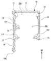
도 4는, 도 3의 IV-IV선에 상당하는 가이드 레일의 단면도이다.
도 5는, 도 3의 IV-IV선에 상당하는 도어 본체 및 행잉 부재의 단면도이다.
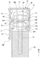
도 6은, 도 3의 IV-IV선에 상당하는 도어 장치의 단면도이다.
도 7은, 도 3의 VII-VII선에 상당하는 단면도이다.
도 8은, 상기 도어 장치에 있어서, 도어 본체 및 행잉 부재가 가이드 레일에 대해서 곡률 반경 방향 외측으로 변위된 상태를 나타내는 단면도이다.
도 9는, 상기 도어 장치에 있어서, 도어 본체 및 행잉 부재가 가이드 레일에 대해서 곡률 반경 방향 내측으로 변위된 상태를 나타내는 단면도이다.
도 10은, 상기 도어 장치에 있어서, 도어 본체 및 행잉 부재가 상하 방향에 대해서 기운 상태를 나타내는 단면도이다.
도 11은, 상기 도어 장치에 있어서, 행잉 부재에 마련된 부시가, 압박 부재에 접촉하기 시작한 상태를 나타내는 단면도이다.
도 12는, 상기 도어 장치에 있어서, 행잉 부재에 마련된 부시가, 압박 부재에 의해 하방으로 압박되고 있는 상태를 나타내는 단면도이다.1 is a perspective view showing a state where a door body is opened in a toilet booth equipped with a door device according to an embodiment of the present invention.
2 is a perspective view showing a state in which a door body is closed in a toilet booth equipped with the door device.
3 is a plan view of a toilet booth equipped with the door device.
4 is a cross-sectional view of the guide rail corresponding to line IV-IV in FIG. 3.
5 is a cross-sectional view of a door body and a hanging member corresponding to line IV-IV in FIG. 3.
6 is a cross-sectional view of the door device corresponding to line IV-IV in FIG. 3.
7 is a cross-sectional view corresponding to line VII-VII in FIG. 3.
8 is a cross-sectional view showing a state in which the door body and the hanging member are displaced outward in the radius of curvature with respect to the guide rail in the door device.
9 is a cross-sectional view showing a state in which the door body and the hanging member are displaced in the radial direction of the curvature with respect to the guide rail in the door device.
10 is a cross-sectional view showing a state in which the door body and the hanging member are inclined with respect to the vertical direction in the door device.
11 is a cross-sectional view showing a state in which the bush provided on the hanging member starts to contact the pressing member in the door device.
12 is a cross-sectional view showing a state in which the bush provided on the hanging member is pressed downward by the pressing member in the door device.
이하, 첨부 도면을 참조하여, 본 발명에 관한 도어 장치의 실시 형태를 설명한다. 그러나, 본 발명은 본 실시 형태에만 한정되는 것은 아니다. 이하의 설명에 있어서, 바닥면 F에 직교하는 방향을 상하 방향(화살표 UP이 상측)이라 하고, 상하 방향으로 직교하는 2방향을 각각 전후 방향(화살표 FR이 전방측) 및 좌우 방향(화살표 LH가 좌측)이라 하여 설명한다.Hereinafter, embodiments of the door device according to the present invention will be described with reference to the accompanying drawings. However, the present invention is not limited to this embodiment. In the following description, the direction orthogonal to the bottom surface F is referred to as the vertical direction (arrow UP is upward), and the two directions orthogonal to the vertical direction are the front-rear direction (arrow FR is the front side) and the left-right direction (arrow LH is Left).
[화장실 부스][Toilet booth]
도 1은, 본 발명의 실시 형태에 관한 도어 장치(1)를 구비한 화장실 부스(2)에 있어서, 도어 본체(20)를 연 상태를 나타내는 사시도이다. 도 2는, 상기 도어 장치(1)를 구비한 화장실 부스(2)에 있어서, 도어 본체(20)를 닫은 상태를 나타내는 사시도이다. 도 3은, 상기 도어 장치(1)를 구비한 화장실 부스(2)의 평면도이다.1 is a perspective view showing a state where the
도 1 내지 도 3에 나타내는 바와 같이, 도어 장치(1)는, 예를 들어 화장실 부스(2)에 마련된다. 화장실 부스(2)는, 구획벽(3)이나, 건물의 벽(9)(도 3 참조)에 의해 구획되어 있다. 화장실 부스(2)의 내측에는, 변기(도시하지 않음) 등이 마련된다. 화장실 부스(2)에는, 이용자가 화장실 부스(2) 내에 드나들기 위한 개구부(4)가 마련되어 있다. 개구부(4)는, 화장실 부스(2) 내로부터 보았을 때, 전방을 향해서 개구되고, 화장실 부스(2)의 내외를 연통한다.1 to 3, the
구획벽(3)은, 바닥면 F로부터 세워 설치되어 있다. 구획벽(3)은, 측벽부(3a)와, 전방 벽부(3b)를 갖는다. 측벽부(3a)는, 좌우 방향으로 간격을 두고 복수가 서로 평행으로 마련되어 있다. 좌우 방향으로 서로 인접하는 두 측벽부(3a)의 사이에, 하나의 화장실 부스(2)가 형성된다. 전방 벽부(3b)는, 화장실 부스(2)의 전단부에 있어서, 좌우 양측에 위치해 있다. 전방 벽부(3b)는, 화장실 부스(2)의 전방면(2f)을 구성한다. 전방 벽부(3b)는, 측벽부(3a)의 전단부에, 측벽부(3a)에 직교하여 마련되어 있다. 또한, 좌우 양측의 측벽부(3a) 중, 한쪽 측 벽부(3a)를, 예를 들어 건물의 벽에 의해 구성하는 것도 가능하다. 또한, 복수의 화장실 부스(2)가 병설되는 경우, 서로 인접하는 화장실 부스(2) 사이에서 하나의 측벽부(3a)가 공용된다.The
<도어 장치><Door device>
도어 장치(1)는, 가이드 레일(10)과, 도어 본체(20)와, 행잉 부재(30)(도 3 참조)를 주로 구비하고 있다.The
<가이드 레일><Guide rail>
가이드 레일(10)은, 알루미늄 합금 등에 의해 형성되어 있다. 가이드 레일(10)은, 평면으로 보아 원호 형상으로 형성되어 있다. 본 실시 형태에 있어서, 가이드 레일(10)은, 화장실 부스(2) 내(전방 벽부(3b)보다도 후방)에 곡률 중심을 갖고, 전방을 향해서 볼록한 반원형으로 형성되어 있다. 이하의 설명에서는, 가이드 레일(10)의 축선(곡률 중심을 지나 상하 방향을 따르는 선)에 직교하는 방향을 곡률 반경 방향이라 하고, 축선 주위의 방향을 연장 방향이라 한다.The
가이드 레일(10)은, 구획벽(3)에, 복수의 브래킷(5A, 5B, 5C)을 통해 고정되어 있다. 브래킷(5A)은, 가이드 레일(10)의 제1 단부(10a)를, 개구부(4)에 대해서 한쪽(우측)에 위치하는 측벽부(3a)에 고정하고 있다. 브래킷(5B)은, 가이드 레일(10)의 중간부(10b)를, 개구부(4)에 대해서 한쪽(우측)에 위치하는 전방 벽부(3b)에 고정하고 있다. 브래킷(5C)은, 가이드 레일(10)의 제2 단부(10c)를, 개구부(4)에 대해서 다른 쪽(좌측)에 위치하는 전방 벽부(3b)에 고정하고 있다. 가이드 레일(10)은, 제1 단부(10a)로부터 중간부(10b)에 걸친 부분이, 한쪽 전방 벽부(3b) 및 한쪽 측벽부(3a)를 따라 마련되어 있다. 가이드 레일(10)은, 중간부(10b)로부터 제2 단부(10c)에 걸친 부분이, 한쪽 전방 벽부(3b)와, 다른 쪽 전방 벽부(3b)에 걸쳐 마련되어 있다. 가이드 레일(10)은, 제1 단부(10a)로부터 제2 단부(10c)를 향한 연장 방향의 일부가, 개구부(4) 상단 테두리를 구획 형성하고 있다. 구체적으로는, 가이드 레일(10)은, 중간부(10b)와 제2 단부(10c) 사이의 부분이, 전방 벽부(3b)의 상단부끼리의 사이에 걸쳐져 있다. 본 실시 형태에 있어서, 가이드 레일(10)의 일부는, 전방 벽부(3b)보다도 전방으로 돌출되어 있다.The
도 4는, 도 3의 IV-IV선에 상당하는 가이드 레일(10)의 단면도이다.4 is a cross-sectional view of the
도 4에 나타내는 바와 같이, 가이드 레일(10)은, 하향 대략 역 ㄷ자형 단면 형상을 갖고 있다. 구체적으로, 가이드 레일(10)은, 상부 판부(11)와, 외주벽부(12)와, 내주벽부(13)를 구비하고 있다. 또한, 가이드 레일(10)은, 연장 방향을 따라 동일 단면 형상을 갖고 있다.As shown in FIG. 4, the
상부 판부(11)는, 가이드 레일(10)의 상면을 형성한다.The
외주벽부(12)는, 상부 판부(11)의 외주연(곡률 반경 방향 외측의 단부 테두리)으로부터 하방으로 늘어뜨려져 있다.The outer
내주벽부(13)는, 상부 판부(11)의 내주연(곡률 반경 방향 내측의 단부 테두리)으로부터 하방으로 늘어뜨려져 있다. 내주벽부(13)는, 외주벽부(12)에 대해서, 곡률 반경 방향 내측으로 간격을 두고 배치되어 있다.The inner
가이드 레일(10)에는, 하향편(16)과, 상부 롤러 지지부(14)와, 하부 롤러 지지부(15)와, 가림부(17)와, 상부 내측 돌기(18)가 형성되어 있다.The
하향편(16)은, 외주벽부(12)에 연속하여 하방으로 연장 돌출되어 있다. 하향편(16)에 있어서의 곡률 반경 방향 외측을 향하는 면은, 외주벽부(12)에 있어서의 곡률 반경 방향 외측을 향하는 면으로 매끄럽게 이어져 있다. 또한, 하향편(16)은, 외주벽부(12)의 하단에, 전체 길이에 걸쳐 형성되어 있다.The
상부 롤러 지지부(14)는, 외주벽부(12)의 상하 방향 중간부로부터, 곡률 반경 방향 내측으로 돌출되어 있다. 상부 롤러 지지부(14)의 상면은, 곡률 반경 방향 외측으로부터 내측을 향해서 점차 하방으로 경사지는 외주 경사면(14f)을 구성하고 있다. 외주 경사면(14f)은, 행잉 부재(30)의 후술하는 상부 롤러(제1 롤러)(32)를 하방으로부터 지지한다.The upper
하부 롤러 지지부(15)는, 내주벽부(13)의 하단부로부터 곡률 반경 방향 외측으로 돌출되어 있다. 하부 롤러 지지부(15)의 상면은, 곡률 반경 방향 내측으로부터 외측을 향해서 점차 하방으로 경사지는 내주 경사면(15f)을 구성하고 있다. 내주 경사면(15f)은, 행잉 부재(30)의 후술하는 하부 롤러(제2 롤러)(33)를 하방으로부터 지지한다.The lower
가림부(17)는, 외주벽부(12)의 하단부로부터 곡률 반경 방향 내측으로 돌출되어 있다. 가림부(17)의 하면 및 하부 롤러 지지부(15)의 하면은, 상하 방향으로 동일한 높이에 위치해 있다. 가림부(17)의 상면(17f)은, 상하 방향에 직교하는 평탄면으로 형성되어 있다.The
상부 내측 돌기(18)는, 외주벽부(12) 및 내주벽부(13) 각각에 있어서, 상부 롤러 지지부(14)보다도 상방이며, 상부 판부(11)로부터 하방으로 이격된 위치에 형성되어 있다. 상부 내측 돌기(18)는, 외주벽부(12) 및 내주벽부(13) 각각으로부터, 가이드 레일(10)의 내측을 향해서 돌출되어 있다. 가이드 레일(10) 내에 있어서, 상부 내측 돌기(18)보다도 하방의 공간은, 롤러(32, 33)가 주행하는 롤러 주행 공간(10r)을 구성한다. 한편, 가이드 레일(10) 내에 있어서, 상부 내측 돌기(18)보다도 상방의 공간은, 후술하는 스토퍼 부재(50)의 압박 부재(53)가 설치되는 설치 공간(10s)을 구성한다.The upper
<도어 본체><Door body>
도 1 내지 도 3에 나타내는 바와 같이, 도어 본체(20)는, 개구부(4)를 개폐한다. 도어 본체(20)는, 평면으로 보아 원호형이며, 가이드 레일(10)과 거의 동일한 곡률 반경으로 형성되어 있다. 도어 본체(20)는, 연장 방향의 길이가, 가이드 레일(10)의 연장 방향의 길이의 1/2 정도로 되어 있다. 구체적으로, 도어 본체(20)에 있어서의 연장 방향의 길이는, 도어 본체(20)의 폐쇄 상태에 있어서, 개구부(4)를 폐색 가능한 길이로 설정되어 있다. 도어 본체(20)는, 하단(20b)이 바닥면 F로부터 상방으로 이격된 상태로, 행잉 부재(30)에 의해 가이드 레일(10)에 현수되어 있다. 도어 본체(20)는, 목질계 재료나 수지계 재료, 금속계 재료 등, 적당한 재료로 형성된다.1 to 3, the
또한, 도어 본체(20)에는, 도어 본체(20)를 개폐 동작시킬 때 이용자가 파지하는 핸들이나, 도어 본체(20)를 폐쇄 상태로 유지하는 로크 기구, 화장실 부스(2)가 사용 중인지 여부(도어 본체(20)가 폐쇄 상태인지 여부)를 나타내는 인디케이터 기구, 이용자가 윗도리나 짐 등을 걸 수 있는 훅(모두 도시하지 않음) 등이 마련된다.In addition, whether or not the
<행잉 부재><Hanging absence>
도 5는, 도 3의 IV-IV선에 상당하는 도어 본체(20) 및 행잉 부재(30)의 단면도이다.5 is a cross-sectional view of the
도 5에 나타내는 바와 같이, 행잉 부재(30)는, 도어 본체(20)를 현수한 상태로, 가이드 레일(10) 내를 이동 가능하게 구성되어 있다. 구체적으로, 행잉 부재(30)는, 지지축(31)과, 상부 롤러(32)와, 하부 롤러(33)와, 부시(40)를 구비하고 있다. 또한, 도 3에 나타내는 바와 같이, 행잉 부재(30)는, 도어 본체(20)의 상단(20t)에, 연장 방향으로 간격을 둔 복수 개소에 마련되어 있다.As shown in FIG. 5, the hanging
도 5에 나타내는 바와 같이, 지지축(31)은, 외주면에 나사 홈이 형성된 수나사 부재로 이루어진다. 지지축(31)은, 도어 본체(20)의 상단(20t)으로부터 상방으로 돌출된 상태에서, 도어 본체(20)의 상단(20t)에 나사 삽입되어 있다. 이에 의해, 지지축(31)은, 상하 방향을 축방향으로 하여 연장하고 있다.As shown in Fig. 5, the
상부 롤러(32)는, 베어링(32b)을 거쳐서, 지지축(31) 주위로 회전 가능하게 마련되어 있다. 상부 롤러(32)의 하단 외주연에는, 소정의 곡률 반경으로 형성된 원호형 단면의 주연부(32s)가 형성되어 있다. 상부 롤러(32)의 외주면(32f)은, 하방으로부터 상방을 향해서 점차 직경 방향 내측으로 경사져 있다. 즉, 상부 롤러(32)는, 하방으로부터 상방을 향함에 따라서 점차 축경되는 테이퍼형으로 형성되어 있다.The
하부 롤러(33)는, 지지축(31) 중 상부 롤러(32)보다도 하방에 위치하는 부분에, 스페이서(39A)를 개재하여 마련되어 있다. 하부 롤러(33)는, 베어링(33b)을 통해, 지지축(31) 주위로 회전 가능하게 마련되어 있다. 하부 롤러(33)는, 상부 롤러(32)와는 별도로, 독립하여 회전 가능하게 되어 있다. 하부 롤러(33)의 하단 외주연에는, 소정의 곡률 반경으로 형성된 원호형 단면의 주연부(33s)가 형성되어 있다. 하부 롤러(33)의 외주면(33f)은, 하방으로부터 상방을 향해서 점차 직경 방향 내측으로 경사져 있다. 즉, 하부 롤러(33)는, 하방으로부터 상방을 향함에 따라서 점차 축경되는 테이퍼형으로 형성되어 있다.The
상부 롤러(32) 및 하부 롤러(33)는, 수지계 재료나 고무계 재료 등에 의해 각각 형성되어 있는 것이 바람직하다.The
부시(40)는, 지지축(31)의 상단부에 마련되어 있다. 부시(40)는, 적어도 상단부가 상술한 설치 공간(10s) 내에 위치해 있다. 부시(40)는, 링형으로 형성되어 있다. 본 실시 형태에 있어서, 부시(40)는, 하방으로부터 상방을 향해서 외경 치수가 점차 축소되는 테이퍼형으로 형성되어 있다. 부시(40)에 있어서의 하단부의 외경은, 상부 롤러(32)에 있어서의 상단부의 외경과 동등하게 되어 있다. 부시(40)의 상면(40t)은, 상하 방향에 직교하는 평탄면으로 형성되어 있다. 또한, 부시(40)의 내측에는, 지지축(31)의 상단부(헤드부)가 수용되어 있다. 즉, 지지축(31)은, 부시(40)의 상단면보다도 상방으로 돌출되어 있지 않다. 부시(40)는, 수지계 재료나 고무계 재료 등, 탄성 변형 가능한 재료에 의해 형성되는 것이 바람직하다.The
도 6은, 도 3의 IV-IV선에 상당하는 도어 장치(1)의 단면도이다.6 is a cross-sectional view of the
도 6에 나타내는 바와 같이, 행잉 부재(30)는, 상부 롤러(32)의 주연부(32s)가 상부 롤러 지지부(14)의 외주 경사면(14f) 상에 지지되고, 하부 롤러(33)의 주연부(33s)가 하부 롤러 지지부(15)의 내주 경사면(15f) 상에 지지된다. 이 상태에서, 하향편(16)의 하단(16b)은, 도어 본체(20)의 상단(20t)보다도 하방에 위치해 있다. 또한, 가림부(17)는, 하방으로부터 보았을 때, 외주벽부(12)와 행잉 부재(30)의 간극의 일부를 막고 있다.6, in the hanging
이용자에 의해, 도어 본체(20)가, 가이드 레일(10)을 따라 이동되면, 상부 롤러(32)는, 외주 경사면(14f) 상에서 지지축(31) 주위로 전동한다. 한편, 하부 롤러(33)는, 내주 경사면(15f) 상에서 지지축(31) 주위로 상부 롤러(32)와는 역방향으로 전동한다.When the door
도 7은, 도 3의 VII-VII선에 상당하는 단면도이다.7 is a cross-sectional view corresponding to line VII-VII in FIG. 3.
도 1, 도 7에 나타내는 바와 같이, 가이드 레일(10) 내의 제1 단부(10a)에는, 스토퍼 부재(50)가 마련되어 있다. 도 7에 나타내는 바와 같이, 스토퍼 부재(50)는, 베이스 부재(51)와, 고무 스토퍼(52)와, 압박 부재(53)를 구비한다.1 and 7, a
베이스 부재(51)는, 직육면체 형상으로 형성되어 있다. 베이스 부재(51)는, 나사못(도시하지 않음)에 의해, 가이드 레일(10)의 상부 판부(11)의 하면에 고정되어 있다. 베이스 부재(51)는, 금속 재료나 수지 재료 등에 의해 형성되어 있는 것이 바람직하다.The
고무 스토퍼(52)는, 베이스 부재(51)에 있어서, 가이드 레일(10)의 연장 방향으로 제2 단부(10c)측(도 7에 있어서 지면 좌측)을 향하는 측면(51a)에 설치되어 있다. 고무 스토퍼(52)에는, 고무 스토퍼(52)를 상하 방향으로 관통하는 관통 구멍(52h)이 형성되어 있다. 고무 스토퍼(52)의 상면(52t)은, 베이스 부재(51)로부터 이격됨에 따라서, 베이스 부재(51)의 상면(51c)과 동일한 높이로부터 점차 낮아지도록 경사져 있다. 고무 스토퍼(52)는, 고무계 재료로 이루어지고, 베이스 부재(51)의 측면(51a)에 접근·이격되는 방향(연장 방향)으로 탄성 변형 가능하다.The
압박 부재(53)는, 평면으로 보아 직사각 형상의 띠판형을 이루고 있다. 압박 부재(53)의 기단부(53a)는, 베이스 부재(51)의 상면(51c)에 고정되어 있다. 기단부(53a)는, 베이스 부재(51)와 가이드 레일(10)의 상부 판부(11)의 사이에 끼워 넣어진다. 압박 부재(53) 중, 기단부(53a)보다도 선단측은, 상술한 설치 공간(10s) 내에서 연장 방향에 따르는 제2 단부(10c)측으로 외팔보식으로 연장 돌출되어 있다. 압박 부재(53)는, 금속 재료 등에 의해 형성되고, 그 판 두께 방향으로 탄성 변형 가능하게 되어 있다.The pressing
압박 부재(53)는, 기단부(53a)로부터 선단부(53b)를 향해서, 제1 경사부(53c), 주 가압부(53d) 및 제2 경사부(53e)를 갖고 있다.The pressing
선단부(53b)는, 상부 판부(11)의 하면에 맞닿아 있다. 단, 선단부(53b)는, 상부 판부(11)로부터 이격되어 있어도 된다.The
제1 경사부(53c)는, 기단부(53a)로부터 선단부(53b)를 향함에 따라서 점차 하방으로 경사져 있다. 제1 경사부(53c)는, 고무 스토퍼(52)의 상면(52t)에 상방으로부터 근접한다.The first
주 가압부(53d)는, 제1 경사부(53c)의 선단으로부터 연장 방향을 따라 거의 수평으로 연장되어 있다.The main
제2 경사부(53e)는, 주 가압부(53d)로부터 선단부(53b)를 향해서 점차 상방으로 경사져 있다.The second
이러한 도어 장치(1)는, 행잉 부재(30)를 개재하여 가이드 레일(10)에 지지된 도어 본체(20)가, 가이드 레일(10)을 따라 이동함으로써, 개구부(4)를 개폐한다. 도 6에 나타낸 바와 같이, 행잉 부재(30)는, 상부 롤러(32)의 주연부(32s)가, 외주 경사면(14f)에 하방으로부터 지지되고, 하부 롤러(33)의 주연부(33s)가 내주 경사면(15f)에 하방으로부터 지지된다.In the
가이드 레일(10)을 따라 도어 본체(20)를 이동시키면, 상부 롤러(32)는, 주연부(32s)가 외주 경사면(14f)에 접하면서 지지축(31) 주위로 회전한다. 하부 롤러(33)는, 주연부(33s)가 내주 경사면(15f)에 접하면서 지지축(31) 주위로 회전한다. 이때, 상부 롤러(32) 및 하부 롤러(33)는, 서로 역방향으로 회전한다. 또한, 지지축(31)이 가이드 레일(10) 내의 곡률 반경 방향 중심에 위치하는 상태(상부 롤러(32)가 외주 경사면(14f)에 지지되고, 하부 롤러(33)가 내주 경사면(15f)에 지지된 상태)를, 도어 본체(20) 및 행잉 부재(30)의 정규 위치라 한다.When the
도 8은, 상기 도어 장치(1)에 있어서, 도어 본체(20) 및 행잉 부재(30)가 가이드 레일(10)에 대해서 곡률 반경 방향 외측으로 변위된 상태를 나타내는 단면도이다.8 is a cross-sectional view showing a state in which the
도 8에 나타내는 바와 같이, 예를 들어 도어 본체(20)에 대해서 곡률 반경 방향 외측을 향해서 외력 등이 작용하면, 도어 본체(20)와 함께 행잉 부재(30)가 곡률 반경 방향 외측으로 변위된다. 이때, 상부 롤러(32)가 외주 경사면(14f)을 따라 변위됨으로써, 도어 본체(20) 및 행잉 부재(30)는 곡률 반경 방향 외측을 향함에 따라서 상방으로 변위된다. 도어 본체(20) 및 행잉 부재(30)의 변위 후, 도어 본체(20) 및 행잉 부재(30)의 자중에 의해 상부 롤러(32)가 외주 경사면(14f) 위를 내려간다. 그 때문에, 도어 본체(20) 및 행잉 부재(30)는 곡률 반경 방향 내측을 향함에 따라서 하방으로 변위된다. 이에 의해, 도어 본체(20) 및 행잉 부재(30)는, 정규 위치로 복귀한다.As shown in FIG. 8, when an external force or the like acts toward the outer side of the curvature radial direction with respect to the
도 9는, 상기 도어 장치(1)에 있어서, 도어 본체(20) 및 행잉 부재(30)가 가이드 레일(10)에 대해서 곡률 반경 방향 내측으로 변위된 상태를 나타내는 단면도이다.9 is a cross-sectional view showing a state in which the
도 9에 나타내는 바와 같이, 예를 들어 도어 본체(20)에 대해서 곡률 반경 방향 내측을 향해서 외력 등이 작용하면, 도어 본체(20)와 함께 행잉 부재(30)가 곡률 반경 방향 내측으로 변위된다. 이때, 하부 롤러(33)가 내주 경사면(15f)을 따라 변위됨으로써, 도어 본체(20) 및 행잉 부재(30)는 곡률 반경 방향 내측을 향함에 따라서 상방으로 변위된다. 도어 본체(20) 및 행잉 부재(30)의 변위 후, 도어 본체(20) 및 행잉 부재(30)의 자중에 의해 하부 롤러(33)가 내주 경사면(15f) 위를 내려간다. 그 때문에, 도어 본체(20) 및 행잉 부재(30)는 곡률 반경 방향 외측을 향함에 따라서 하방으로 변위된다. 이에 의해, 도어 본체(20) 및 행잉 부재(30)는, 정규 위치로 복귀한다.As illustrated in FIG. 9, when an external force or the like acts toward the inside of the curvature radially with respect to the
이와 같이, 가령 도어 본체(20)가 가이드 레일(10)에 대해서 곡률 반경 방향으로 위치 어긋난 경우라도, 자중에 의해 정규 위치로 복귀하게 되어 있다.Thus, even if the door
도 10은, 상기 도어 장치(1)에 있어서, 도어 본체(20) 및 행잉 부재(30)가 상하 방향에 대해서 기운 상태를 나타내는 단면도이다.10 is a cross-sectional view showing a state in which the door
도 10에 나타내는 바와 같이, 도어 본체(20)에 곡률 반경 방향의 내측을 향해서 외력 등이 작용한 경우, 도어 본체(20) 및 행잉 부재(30)가, 상부 롤러(32)와 외주 경사면(14f)의 접촉 부분을 기점에 상하 방향으로 대해서 기우는 경우가 있다. 이 경우에 있어서, 본 실시 형태에서는, 상부 롤러(32)의 외주면(32f) 및 하부 롤러(33)의 외주면(33f)이 하방으로부터 상방을 향해서 점차 축경되고 있으므로, 외주면(32f, 33f)이 가이드 롤러의 외주벽부(12)나 내주벽부(13)에 접촉하기 어렵게 되어 있다.As shown in Fig. 10, when an external force or the like acts toward the inside of the radius of curvature on the
도 11은, 상기 도어 장치(1)에 있어서, 행잉 부재(30)에 마련된 부시(40)가, 압박 부재(53)에 접촉하기 시작한 상태를 나타내는 단면도이다.11 is a cross-sectional view showing a state in which the
도 11에 나타내는 바와 같이, 도어 본체(20)가 개방 방향(도 11에 있어서 지면 우측 방향)으로 이동하고, 행잉 부재(30)가 스토퍼 부재(50)의 압박 부재(53)에 도달하면, 부시(40)가 압박 부재(53)에 맞닿는다. 부시(40)는, 먼저 압박 부재(53)의 제2 경사부(53e)에 접촉한 후, 압박 부재(53)를 상방(압박 부재(53)의 가압력에 저항하는 방향)으로 밀어올리면서 개방 방향으로 이동시킨다. 압박 부재(53)의 상방에 대한 변형량이 커짐에 따라서(부시(40)와 압박 부재(53)가 접촉 후, 부시(40)의 개방 방향에 대한 이동량이 증가함에 따라서), 압박 부재(53)로부터 부시(40)에 작용하는 하방에 대한 압박력이 증가한다. 이에 의해, 부시(40)와 압박 부재(53)의 사이에 발생하는 마찰력이 점차 커져, 행잉 부재(30)(및 도어 본체(20))의 이동 속도가 저감된다.As shown in Fig. 11, when the
도 12는, 상기 도어 장치(1)에 있어서, 행잉 부재(30)에 마련된 부시(40)가, 압박 부재(53)에 의해 하방으로 압박되고 있는 상태를 나타내는 단면도이다.12 is a cross-sectional view showing a state in which the
도 12에 나타내는 바와 같이, 부시(40)가, 제2 경사부(53e)를 통과하여, 주 가압부(53d)까지 도달하면, 압박 부재(53)로부터 부시(40)에 작용하는 하방에 대한 압박력(주 가압부(53d)와 부시(40)의 사이에서 발생하는 마찰력)이 최대로 된다. 이에 의해, 행잉 부재(30)(및 도어 본체(20))의 개방 방향으로의 이동이 규제되어, 도어 본체(20)가 개방 위치에서 보유 지지된다. 또한, 가령 부시(40)가 주 가압부(53d)를 통과하였다고 해도, 그 후 부시(40)는 고무 스토퍼(52)에 맞부딪침으로써, 도어 본체(20)의 개방 방향으로의 이동이 규제된다.As shown in FIG. 12, when the
이와 같이, 본 실시 형태에서는, 가이드 레일(10)이, 외주벽부(12)로부터 곡률 반경 방향 내측으로 돌출되어서 상부 롤러(32)의 주연부(32s)를 하방으로부터 지지하고, 곡률 반경 방향 외측으로부터 내측을 향해서 점차 하방으로 경사지는 외주 경사면(14f)과, 내주벽부(13)로부터 곡률 반경 방향 외측으로 돌출되어서 하부 롤러(33)의 주연부(33s)를 하방으로부터 지지하고, 곡률 반경 방향 내측으로부터 외측을 향해서 점차 하방으로 경사지는 내주 경사면(15f)을 갖는 구성으로 하였다.As described above, in the present embodiment, the
이와 같은 구성에 따르면, 도어 본체(20)와 함께 행잉 부재(30)가 가이드 레일(10)의 곡률 반경 방향의 외측이나 내측으로 변위되어도, 도어 본체(20) 및 행잉 부재(30)의 자중에 의해 상부 롤러(32) 및 하부 롤러(33)가 외주 경사면(14f) 또는 내주 경사면(15f) 위를 이동함으로써, 도어 본체(20) 및 행잉 부재(30)가 정규 위치로 복귀한다. 이에 의해, 가이드 레일(10)에 대해서 도어 본체(20)가 곡률 반경 방향으로 위치 어긋나는 것을 억제할 수 있다. 그 결과, 이상음의 발생이나, 도어 본체(20)나 행잉 부재(30)와 가이드 레일(10)의 간섭을 억제할 수 있다. 그 결과, 도어 본체(20)의 개폐 동작을 원활하게 행하는 것이 가능해진다.According to such a configuration, even if the hanging
본 실시 형태에서는, 상부 롤러(32) 및 하부 롤러(33)의 외주면(32f, 33f)이, 하방으로부터 상방을 향해서 점차 직경 방향 내측으로 경사져 있는 구성으로 하였다.In the present embodiment, the outer
이 구성에 따르면, 도어 본체(20)와 함께 행잉 부재(30)가 기울어도, 외주면(32f, 33f)이 가이드 롤러의 외주벽부(12)나 내주벽부(13)에 접촉하기 어려워진다. 이에 의해, 도어 본체(20)의 개폐 동작 시에 도어 본체(20)가 기울었다고 해도, 가이드 레일(10)과 상부 롤러(32) 또는 하부 롤러(33)의 사이에 작용하는 마찰 저항이 증가하는 것을 억제할 수 있다. 이에 의해, 도어 본체(20)의 개폐 동작을 원활하게 행할 수 있다.According to this configuration, even if the hanging
본 실시 형태에서는, 외주벽부(12)의 하단부로부터 하방을 향해서 연장 돌출되는 하향편(16)을 구비하는 구성으로 하였다.In this embodiment, it is set as the structure provided with the
이 구성에 따르면, 도어 본체(20)의 상단(20t)이나 행잉 부재(30) 등이 하향편(16)에 의해 곡률 반경 방향 외측으로부터 덮이기 때문에, 도어 장치(1)를 곡률 반경 방향 외측으로부터 보았을 때의 도어 장치(1)의 외관을 향상시킬 수 있다.According to this configuration, since the
본 실시 형태에서는, 외주벽부(12)의 하단부로부터, 곡률 반경 방향 내측으로 돌출되어, 외주벽부(12)와 행잉 부재(30)의 간극의 일부를 막는 가림부(17)를 추가로 구비하는 구성으로 하였다.In the present embodiment, the configuration further includes a
이 구성에 따르면, 가이드 레일(10)을 하방으로부터 보았을 때, 가이드 레일(10)의 내측이 노출되는 것을 억제할 수 있다. 이에 의해, 도어 장치(1)의 외관을 더욱 향상시킬 수 있다.According to this configuration, when the
본 실시 형태에서는, 가이드 레일(10)의 제1 단부(10a)에, 부시(40)를 하방을 향해서 압박하는 압박 부재(53)가 마련되어 있는 구성으로 하였다.In the present embodiment, the
이 구성에 따르면, 도어 본체(20)의 개폐 동작 시에 있어서, 행잉 부재(30)의 부시(40)가 압박 부재(53)에 의해 하방으로 압박되면, 행잉 부재(30)(도어 본체(20))의 이동 속도가 저감된다. 그 때문에, 도어 본체(20)가 개방 방향의 종단부에 도달했을 때의 충격을 억제할 수 있다. 또한, 압박 부재(53)에 의해 부시(40)를 하방을 향해서 압박함으로써, 도어 본체(20) 및 행잉 부재(30)가 가이드 레일(10)을 따라 부주의하게 이동하지 않도록, 정지 상태를 유지할 수 있다.According to this configuration, during the opening / closing operation of the
또한, 행잉 부재(30)가 압박 부재(53)를 통과할 때, 도어 본체(20)와 함께 행잉 부재(30)가 가이드 레일(10)의 곡률 반경 방향의 외측 또는 내측으로 변위된 경우에는, 압박 부재(53)에 의해 부시(40)가 하방을 향해서 압박됨으로써, 상부 롤러(32) 및 하부 롤러(33)가, 외주 경사면(14f)이나 내주 경사면(15f) 위를 전달되어서 하방으로 안내된다. 이에 의해, 행잉 부재(30) 및 도어 본체(20)가 정규 위치로 복귀하고, 도어 본체(20)의 곡률 반경 방향으로의 변위를 억제할 수 있다. 그 결과, 도어 본체(20)가 가이드 레일(10)의 곡률 반경 방향 외측이나 내측으로 어긋나는 것을 억제하여, 이상음의 발생이나, 도어 본체(20)나 행잉 부재(30)와 가이드 레일(10)의 간섭을 억제할 수 있다. 그 결과, 도어 본체(20)의 개폐 동작을 원활하게 행하는 것이 가능해진다.Further, when the hanging
(기타 실시 형태)(Other embodiments)
이상, 본 발명의 바람직한 실시예를 설명했지만, 본 발명은 이들 실시예에 한정되지는 않는다. 본 발명의 취지를 벗어나지 않는 범위에서, 구성의 부가, 생략, 치환 및 기타의 변경이 가능하다. 본 발명은 상술한 설명에 의해 한정되지 않고, 첨부의 특허 청구 범위에 의해서만 한정된다.The preferred embodiments of the present invention have been described above, but the present invention is not limited to these embodiments. Addition, omission, substitution, and other changes in the configuration are possible without departing from the spirit of the present invention. The present invention is not limited by the above description, but only by the appended claims.
예를 들어, 상술한 실시 형태에서는, 외주 경사면(14f)을 갖는 상부 롤러 지지부(14)를 외주벽부(12)에 마련하고, 내주 경사면(15f)을 갖는 하부 롤러 지지부(15)를 내주벽부(13)에 마련하도록 했지만, 이것에 한정되지 않는다. 상부 롤러 지지부(14)를 내주벽부(13)에 마련하고, 하부 롤러 지지부(15)를 외주벽부(12)에 마련하도록 해도 된다.For example, in the above-described embodiment, the upper
상술한 실시 형태에서는, 스토퍼 부재(50)를, 가이드 레일(10)의 제1 단부(10a)에 마련하도록 했지만, 제2 단부(10c)에 마련해도 되고, 양단부(10a, 10c)에 마련해도 된다.In the above-mentioned embodiment, although the
도어 본체(20)를, 개방 방향 또는 폐쇄 방향으로 가압하기 위한 기구를 구비해도 된다.A mechanism for pressing the
상술한 실시 형태에서는, 도어 장치(1)를, 화장실 부스(2)에 마련하도록 했지만, 도어 장치(1)의 용도는, 화장실 부스(2)에 한정되지 않고, 다른 여러 가지 용도에 사용하는 것이 가능하다.In the above-mentioned embodiment, although the
기타, 본 발명의 취지를 벗어나지 않는 범위에서, 상술한 실시 형태에 있어서의 구성 요소를 주지의 구성 요소로 치환하는 것은 적절히 가능하고, 또한, 상술한 각 변형예를 적절히 조합해도 된다.In addition, in the range which does not deviate from the gist of the present invention, it is possible to appropriately replace the components in the above-described embodiments with well-known components, and the above-described respective modifications may be appropriately combined.
1: 도어 장치
10: 가이드 레일
10a: 제1 단부(단부)
10s: 설치 공간
12: 외주벽부
13: 내주벽부
14f: 외주 경사면
15f: 내주 경사면
16: 하향편
16b: 하단
17: 가림부
20: 도어 본체
20t: 상단
30: 행잉 부재
31: 지지축
32: 상부 롤러(제1 롤러)
32f: 외주면
32s: 주연부
33: 하부 롤러(제2 롤러)
33f: 외주면
33s: 주연부
40: 부시
53: 압박 부재1: Door device
10: guide rail
10a: first end (end)
10s: installation space
12: outer wall
13: inner peripheral wall
14f: outer slope
15f: Inner periphery
16: Downward
16b: bottom
17: cover part
20: door body
20t: top
30: Hanging member
31: support shaft
32: upper roller (first roller)
32f: outer peripheral surface
32s: leading edge
33: lower roller (second roller)
33f: outer circumference
33s: leading edge
40: Bush
53: no pressure
Claims (5)
도어 본체와,
상기 도어 본체의 상부에 마련되어, 상기 가이드 레일의 연장 방향을 따라 이동 가능하게 마련된 행잉 부재를 구비하고,
상기 행잉 부재는,
상기 도어 본체로부터 상방을 향해서 연장되는 지지축과,
상기 지지축 주위로 회전 가능하게 마련된 제1 롤러와,
상기 제1 롤러의 하방에 마련되고, 상기 지지축 주위로 회전 가능하게 마련된 제2 롤러를 구비하고,
상기 가이드 레일은,
상기 가이드 레일의 곡률 반경 방향 외측에 마련된 외주벽부와,
상기 외주벽부에 대해서 상기 곡률 반경 방향 내측으로 간격을 두고 마련된 내주벽부와,
상기 외주벽부로부터 상기 곡률 반경 방향 내측으로 돌출되어서 상기 제1 롤러 및 상기 제2 롤러 중, 한쪽 롤러의 주연부를 하방으로부터 지지하고, 상기 곡률 반경 방향 외측으로부터 내측을 향해서 점차 하방으로 경사지는 외주 경사면과,
상기 내주벽부로부터 상기 곡률 반경 방향 외측으로 돌출되어서 상기 제1 롤러 및 상기 제2 롤러 중, 다른 쪽 롤러 주연부를 하방으로부터 지지하고, 상기 곡률 반경 방향 내측으로부터 외측을 향해서 점차 하방으로 경사지는 내주 경사면을 갖는, 도어 장치.A guide rail provided in an arc shape when viewed in a plan view,
The door body,
It is provided on the upper portion of the door body, and has a hanging member provided to be movable along the extending direction of the guide rail,
The hanging member,
A support shaft extending upward from the door body,
A first roller rotatably provided around the support shaft,
A second roller is provided below the first roller and is rotatably provided around the support shaft.
The guide rail,
An outer circumferential wall portion provided on the outer side in a radius of curvature of the guide rail,
An inner circumferential wall portion spaced in the radial direction of the curvature with respect to the outer circumference wall portion
An outer circumferential surface protruding from the outer circumferential wall portion in the radial direction and supporting a peripheral portion of one roller of the first roller and the second roller from below, and gradually inclining downward from the outer side in the radius of curvature toward the inside ,
An inner circumferential slope that protrudes outward from the inner circumferential wall portion in the radial direction of the curvature, supports the other roller peripheral portion from below, and gradually inclines downward from the inside in the radius of curvature to the outside. Having, the door device.
상기 제1 롤러 및 상기 제2 롤러의 외주면은, 하방으로부터 상방을 향해서 점차 직경 방향 내측으로 경사져 있는 것을 특징으로 하는, 도어 장치.According to claim 1,
The door device according to claim 1, wherein outer surfaces of the first roller and the second roller gradually incline in the radial direction from the bottom to the top.
상기 가이드 레일은, 상기 외주벽부의 하단부로부터 하방을 향해서 연장 돌출되는 하향편을 구비하고,
상기 하향편의 하단은, 상기 도어 본체의 상단보다도 하방에 위치해 있는, 도어 장치.The method according to claim 1 or 2,
The guide rail is provided with a downward piece protruding downward from the lower end of the outer peripheral wall portion,
The lower end of the downward piece is located below the upper end of the door body, the door device.
상기 가이드 레일은, 상기 외주벽부 및 상기 내주벽부 중, 한쪽 벽부의 하단부로부터, 상기 곡률 반경 방향을 따라 상기 행잉 부재측으로 돌출됨과 함께, 상기 한쪽 벽부와 상기 행잉 부재의 간극의 일부를 막는 가림부를 구비하고 있는 것을 특징으로 하는, 도어 장치.The method according to any one of claims 1 to 3,
The guide rail, among the outer circumferential wall portion and the inner circumferential wall portion, protrudes from the lower end portion of the one wall portion along the radius of curvature to the hanging member side, and hides a portion of the gap between the one wall portion and the hanging member. A door device characterized in that it is provided.
상기 행잉 부재는, 상기 지지축의 상단부에 마련된 부시를 구비하고,
상기 가이드 레일의 연장 방향의 적어도 한쪽 단부에, 상기 부시를 하방을 향해서 압박하는 압박 부재가 마련되어 있는, 도어 장치.The method according to any one of claims 1 to 4,
The hanging member is provided with a bush provided on the upper end of the support shaft,
A door device is provided on at least one end portion of the guide rail in the extending direction to press the bush downward.
Applications Claiming Priority (2)
| Application Number | Priority Date | Filing Date | Title |
|---|---|---|---|
| JP2018192120A JP7182420B2 (en) | 2018-10-10 | 2018-10-10 | door device |
| JPJP-P-2018-192120 | 2018-10-10 |
Publications (1)
| Publication Number | Publication Date |
|---|---|
| KR20200040646A true KR20200040646A (en) | 2020-04-20 |
Family
ID=70219441
Family Applications (1)
| Application Number | Title | Priority Date | Filing Date |
|---|---|---|---|
| KR1020190065823A KR20200040646A (en) | 2018-10-10 | 2019-06-04 | Door device |
Country Status (2)
| Country | Link |
|---|---|
| JP (1) | JP7182420B2 (en) |
| KR (1) | KR20200040646A (en) |
Cited By (1)
| Publication number | Priority date | Publication date | Assignee | Title |
|---|---|---|---|---|
| US11851928B2 (en) | 2020-02-18 | 2023-12-26 | Assa Abloy Entrance Systems Ab | Revolving door mounting arrangement |
Families Citing this family (1)
| Publication number | Priority date | Publication date | Assignee | Title |
|---|---|---|---|---|
| JP7348126B2 (en) | 2020-03-30 | 2023-09-20 | 三菱重工業株式会社 | Control device, control input determination method, and control input determination program |
Citations (1)
| Publication number | Priority date | Publication date | Assignee | Title |
|---|---|---|---|---|
| JPS5536416B2 (en) | 1978-03-17 | 1980-09-20 |
Family Cites Families (5)
| Publication number | Priority date | Publication date | Assignee | Title |
|---|---|---|---|---|
| JPS6030395Y2 (en) * | 1979-12-29 | 1985-09-11 | 松下電工株式会社 | bifold door |
| JP2500509Y2 (en) * | 1990-02-23 | 1996-06-05 | 松下電工株式会社 | Partition panel traveling device |
| JPH09189166A (en) * | 1996-01-10 | 1997-07-22 | Hazama Gumi Ltd | Fixing mechanism of fitting |
| JP2000337013A (en) | 1999-05-31 | 2000-12-05 | Okamura Corp | Door device of overhang door type |
| JP6316699B2 (en) | 2014-08-05 | 2018-04-25 | 三和スピンドル建材株式会社 | Suspended runner device for movable partitions |
-
2018
- 2018-10-10 JP JP2018192120A patent/JP7182420B2/en active Active
-
2019
- 2019-06-04 KR KR1020190065823A patent/KR20200040646A/en unknown
Patent Citations (1)
| Publication number | Priority date | Publication date | Assignee | Title |
|---|---|---|---|---|
| JPS5536416B2 (en) | 1978-03-17 | 1980-09-20 |
Cited By (1)
| Publication number | Priority date | Publication date | Assignee | Title |
|---|---|---|---|---|
| US11851928B2 (en) | 2020-02-18 | 2023-12-26 | Assa Abloy Entrance Systems Ab | Revolving door mounting arrangement |
Also Published As
| Publication number | Publication date |
|---|---|
| JP7182420B2 (en) | 2022-12-02 |
| JP2020060045A (en) | 2020-04-16 |
Similar Documents
| Publication | Publication Date | Title |
|---|---|---|
| KR20200040646A (en) | Door device | |
| US8857498B2 (en) | Track and guide system for a door | |
| JP4486969B2 (en) | Guide device for plate-like objects | |
| GB2363785A (en) | Guiding structure for a moving member such as a lid | |
| JP7182421B2 (en) | door device | |
| JP4827746B2 (en) | Door opening / closing mechanism | |
| JP6516295B2 (en) | Sliding door handrail, sliding door device | |
| KR200399555Y1 (en) | An apparatus for governing opening angle of door | |
| JP3959090B2 (en) | Interlocking sliding door bounce prevention device | |
| KR200447878Y1 (en) | Sliding guide device of folding door | |
| JP4125408B2 (en) | Rotation support mechanism | |
| JPH11351249A (en) | Slide door guide device and its roller device | |
| JP2004084332A (en) | Sliding door device and braking device therefor | |
| JPH083656Y2 (en) | Roller type door guide | |
| JPH087008Y2 (en) | Folding door runner stopper | |
| JP7296159B2 (en) | door mechanism | |
| JP7117038B1 (en) | door mechanism | |
| US1845417A (en) | Door holder | |
| JP6772981B2 (en) | Vehicle sliding door structure | |
| JP2006131314A (en) | Door device for elevator | |
| JP2895416B2 (en) | Top opening door opening and closing device | |
| JP6196876B2 (en) | Key guide structure of keyboard instrument | |
| JP7118858B2 (en) | door device | |
| JP4650957B2 (en) | Folding door bracket | |
| JP7116601B2 (en) | sliding door device |