KR20200039348A - Cleaner and and method for controlling the same - Google Patents
Cleaner and and method for controlling the same Download PDFInfo
- Publication number
- KR20200039348A KR20200039348A KR1020180119165A KR20180119165A KR20200039348A KR 20200039348 A KR20200039348 A KR 20200039348A KR 1020180119165 A KR1020180119165 A KR 1020180119165A KR 20180119165 A KR20180119165 A KR 20180119165A KR 20200039348 A KR20200039348 A KR 20200039348A
- Authority
- KR
- South Korea
- Prior art keywords
- battery
- suction motor
- voltage
- switch
- battery assembly
- Prior art date
Links
- 238000000034 method Methods 0.000 title claims abstract description 28
- 239000003990 capacitor Substances 0.000 claims abstract description 35
- 238000001514 detection method Methods 0.000 claims abstract description 23
- 238000000926 separation method Methods 0.000 claims description 29
- 239000000428 dust Substances 0.000 description 9
- 238000004140 cleaning Methods 0.000 description 7
- 238000010586 diagram Methods 0.000 description 3
- 238000012544 monitoring process Methods 0.000 description 3
- XUIMIQQOPSSXEZ-UHFFFAOYSA-N Silicon Chemical compound [Si] XUIMIQQOPSSXEZ-UHFFFAOYSA-N 0.000 description 1
- 230000002159 abnormal effect Effects 0.000 description 1
- 230000005540 biological transmission Effects 0.000 description 1
- 230000000903 blocking effect Effects 0.000 description 1
- 230000015556 catabolic process Effects 0.000 description 1
- 230000008094 contradictory effect Effects 0.000 description 1
- 238000013500 data storage Methods 0.000 description 1
- 230000003247 decreasing effect Effects 0.000 description 1
- 230000005284 excitation Effects 0.000 description 1
- 238000012423 maintenance Methods 0.000 description 1
- 230000014759 maintenance of location Effects 0.000 description 1
- 230000007257 malfunction Effects 0.000 description 1
- 238000007726 management method Methods 0.000 description 1
- 238000012986 modification Methods 0.000 description 1
- 230000004048 modification Effects 0.000 description 1
- 230000003287 optical effect Effects 0.000 description 1
- 230000003252 repetitive effect Effects 0.000 description 1
- 229910052710 silicon Inorganic materials 0.000 description 1
- 239000010703 silicon Substances 0.000 description 1
- 239000007787 solid Substances 0.000 description 1
- 238000012360 testing method Methods 0.000 description 1
Images


Classifications
-
- A—HUMAN NECESSITIES
- A47—FURNITURE; DOMESTIC ARTICLES OR APPLIANCES; COFFEE MILLS; SPICE MILLS; SUCTION CLEANERS IN GENERAL
- A47L—DOMESTIC WASHING OR CLEANING; SUCTION CLEANERS IN GENERAL
- A47L9/00—Details or accessories of suction cleaners, e.g. mechanical means for controlling the suction or for effecting pulsating action; Storing devices specially adapted to suction cleaners or parts thereof; Carrying-vehicles specially adapted for suction cleaners
- A47L9/28—Installation of the electric equipment, e.g. adaptation or attachment to the suction cleaner; Controlling suction cleaners by electric means
- A47L9/2836—Installation of the electric equipment, e.g. adaptation or attachment to the suction cleaner; Controlling suction cleaners by electric means characterised by the parts which are controlled
- A47L9/2842—Suction motors or blowers
-
- A—HUMAN NECESSITIES
- A47—FURNITURE; DOMESTIC ARTICLES OR APPLIANCES; COFFEE MILLS; SPICE MILLS; SUCTION CLEANERS IN GENERAL
- A47L—DOMESTIC WASHING OR CLEANING; SUCTION CLEANERS IN GENERAL
- A47L9/00—Details or accessories of suction cleaners, e.g. mechanical means for controlling the suction or for effecting pulsating action; Storing devices specially adapted to suction cleaners or parts thereof; Carrying-vehicles specially adapted for suction cleaners
- A47L9/28—Installation of the electric equipment, e.g. adaptation or attachment to the suction cleaner; Controlling suction cleaners by electric means
- A47L9/2805—Parameters or conditions being sensed
- A47L9/2831—Motor parameters, e.g. motor load or speed
-
- A—HUMAN NECESSITIES
- A47—FURNITURE; DOMESTIC ARTICLES OR APPLIANCES; COFFEE MILLS; SPICE MILLS; SUCTION CLEANERS IN GENERAL
- A47L—DOMESTIC WASHING OR CLEANING; SUCTION CLEANERS IN GENERAL
- A47L9/00—Details or accessories of suction cleaners, e.g. mechanical means for controlling the suction or for effecting pulsating action; Storing devices specially adapted to suction cleaners or parts thereof; Carrying-vehicles specially adapted for suction cleaners
- A47L9/28—Installation of the electric equipment, e.g. adaptation or attachment to the suction cleaner; Controlling suction cleaners by electric means
- A47L9/2857—User input or output elements for control, e.g. buttons, switches or displays
-
- A—HUMAN NECESSITIES
- A47—FURNITURE; DOMESTIC ARTICLES OR APPLIANCES; COFFEE MILLS; SPICE MILLS; SUCTION CLEANERS IN GENERAL
- A47L—DOMESTIC WASHING OR CLEANING; SUCTION CLEANERS IN GENERAL
- A47L9/00—Details or accessories of suction cleaners, e.g. mechanical means for controlling the suction or for effecting pulsating action; Storing devices specially adapted to suction cleaners or parts thereof; Carrying-vehicles specially adapted for suction cleaners
- A47L9/28—Installation of the electric equipment, e.g. adaptation or attachment to the suction cleaner; Controlling suction cleaners by electric means
- A47L9/2868—Arrangements for power supply of vacuum cleaners or the accessories thereof
- A47L9/2878—Dual-powered vacuum cleaners, i.e. devices which can be operated with mains power supply or by batteries
-
- A—HUMAN NECESSITIES
- A47—FURNITURE; DOMESTIC ARTICLES OR APPLIANCES; COFFEE MILLS; SPICE MILLS; SUCTION CLEANERS IN GENERAL
- A47L—DOMESTIC WASHING OR CLEANING; SUCTION CLEANERS IN GENERAL
- A47L9/00—Details or accessories of suction cleaners, e.g. mechanical means for controlling the suction or for effecting pulsating action; Storing devices specially adapted to suction cleaners or parts thereof; Carrying-vehicles specially adapted for suction cleaners
- A47L9/28—Installation of the electric equipment, e.g. adaptation or attachment to the suction cleaner; Controlling suction cleaners by electric means
- A47L9/2868—Arrangements for power supply of vacuum cleaners or the accessories thereof
- A47L9/2884—Details of arrangements of batteries or their installation
-
- H—ELECTRICITY
- H02—GENERATION; CONVERSION OR DISTRIBUTION OF ELECTRIC POWER
- H02P—CONTROL OR REGULATION OF ELECTRIC MOTORS, ELECTRIC GENERATORS OR DYNAMO-ELECTRIC CONVERTERS; CONTROLLING TRANSFORMERS, REACTORS OR CHOKE COILS
- H02P7/00—Arrangements for regulating or controlling the speed or torque of electric DC motors
- H02P7/06—Arrangements for regulating or controlling the speed or torque of electric DC motors for regulating or controlling an individual dc dynamo-electric motor by varying field or armature current
- H02P7/18—Arrangements for regulating or controlling the speed or torque of electric DC motors for regulating or controlling an individual dc dynamo-electric motor by varying field or armature current by master control with auxiliary power
- H02P7/24—Arrangements for regulating or controlling the speed or torque of electric DC motors for regulating or controlling an individual dc dynamo-electric motor by varying field or armature current by master control with auxiliary power using discharge tubes or semiconductor devices
- H02P7/28—Arrangements for regulating or controlling the speed or torque of electric DC motors for regulating or controlling an individual dc dynamo-electric motor by varying field or armature current by master control with auxiliary power using discharge tubes or semiconductor devices using semiconductor devices
- H02P7/285—Arrangements for regulating or controlling the speed or torque of electric DC motors for regulating or controlling an individual dc dynamo-electric motor by varying field or armature current by master control with auxiliary power using discharge tubes or semiconductor devices using semiconductor devices controlling armature supply only
- H02P7/29—Arrangements for regulating or controlling the speed or torque of electric DC motors for regulating or controlling an individual dc dynamo-electric motor by varying field or armature current by master control with auxiliary power using discharge tubes or semiconductor devices using semiconductor devices controlling armature supply only using pulse modulation
-
- H—ELECTRICITY
- H03—ELECTRONIC CIRCUITRY
- H03K—PULSE TECHNIQUE
- H03K7/00—Modulating pulses with a continuously-variable modulating signal
- H03K7/08—Duration or width modulation ; Duty cycle modulation
Abstract
Description
본 발명은 본체의 진공 청소기 및 그것의 제어방법에 관한 것으로, 좀 더 구체적으로는 배터리를 사용하여 흡입 모터를 구동하는 진공 청소기 및 그것의 제어방법에 관한 것이다.The present invention relates to a vacuum cleaner of a main body and a control method thereof, and more particularly, to a vacuum cleaner for driving a suction motor using a battery and a control method thereof.
진공 청소기는 청소기 본체의 내부에 장착되는 흡입 모터에서 발생되는 흡입력을 이용하여 먼지와 공기를 흡입하고, 공기로부터 먼지를 분리하여 집진하는 장치를 가리킨다.The vacuum cleaner refers to a device that sucks dust and air using suction power generated by a suction motor mounted inside the cleaner body, separates dust from the air, and collects dust.
이러한 진공 청소기는 캐니스터 청소기, 업라이트 청소기, 스틱 청소기, 핸디 청소기, 및 로봇 청소기로 구분된다. 캐니스터 청소기의 경우 먼지를 흡입하기 위한 흡입 노즐이 청소기 본체와 별도로 구비되며, 연결장치에 의해 청소기 본체와 흡입 노즐이 서로 연결된다. 업라이트 청소기의 경우 흡입 노즐이 청소기 본체와 회전 가능하게 연결된다. 스틱 청소기와 핸디 청소기의 경우 사용자가 청소기 본체를 손으로 파지한 상태로 사용된다. 다만, 스틱 청소기의 경우 흡입 모터가 흡입 노즐에 가깝게 배치되고(하중심), 핸디 청소기의 경우 흡입 모터가 파지부에 가깝게 배치된다(상중심). 로봇 청소기는 자율 주행 시스템을 통해 스스로 주행하면서 스스로 청소를 수행한다. These vacuum cleaners are classified into canister cleaners, upright cleaners, stick cleaners, handy cleaners, and robot cleaners. In the case of a canister cleaner, a suction nozzle for sucking dust is provided separately from the cleaner body, and the cleaner body and the suction nozzle are connected to each other by a connecting device. In the case of an upright cleaner, the suction nozzle is rotatably connected to the cleaner body. In the case of a stick cleaner and a handy cleaner, it is used in a state where the user holds the cleaner body by hand. However, in the case of a stick cleaner, the suction motor is disposed close to the suction nozzle (lower center), and in the case of a handy cleaner, the suction motor is disposed close to the gripping portion (upper center). The robot cleaner cleans itself while driving itself through an autonomous driving system.
한편, 진공 청소기의 경우 사용 편의성을 위해 코드 없이 배터리를 사용한 무선 방식으로 구동될 수 있다. 이러한 진공 청소기가 작동하는 도중 배터리가 진공 청소기로부터 분리된 경우, 작동중인 모터에서 역기전력(Counter electromotive force)이 발생하게 된다. 이러한 역기전력은 인버터 회로의 DC 단 커패시터의 충전 전압과 더해져서 피크(peak), 즉 과전압을 발생시킨다. 그에 따라, 청소기 내 인버터 회로의 부품 소손의 위험성이 증가되고, 이는 잦은 부품 교체를 초래할 수 있다.Meanwhile, in the case of a vacuum cleaner, it can be driven in a wireless manner using a battery without a cord for ease of use. When the battery is disconnected from the vacuum cleaner while the vacuum cleaner is operating, counter electromotive force is generated in the operating motor. This back EMF is added to the charging voltage of the DC stage capacitor of the inverter circuit to generate a peak, that is, an overvoltage. Accordingly, the risk of component burnout of the inverter circuit in the cleaner increases, which may result in frequent component replacement.
이에, 본 발명의 일 목적은, 청소 개시에 따라 흡입 모터의 구동 중에 배터리가 분리되더라도 흡입 모터에서 발생된 역기전력에 의한 인버터의 부품 소손이 방지될 수 있는 진공 청소기 및 그것의 동작방법을 제공하는데 있다.Accordingly, an object of the present invention is to provide a vacuum cleaner and a method of operating the same, which can prevent component damage of the inverter due to back electromotive force generated in the suction motor even if the battery is disconnected during driving of the suction motor according to the start of cleaning. .
또한, 본 발명의 또 다른 목적은 청소 개시에 따라 흡입 모터의 구동 중에 배터리가 분리되었는지 여부를 감지할 수 있고, 인버터에 사용되는 스위칭 소자의 전압용량의 마진을 감소시켜서 인버터 효율이 향상되도록 구현한 진공 청소기 및 그것의 동작방법을 제공하는데 있다.In addition, another object of the present invention can be implemented to detect whether the battery is disconnected while driving the suction motor according to the start of cleaning, and reduce the margin of the voltage capacity of the switching element used in the inverter to improve the inverter efficiency. It is to provide a vacuum cleaner and its operation method.
또한, 본 발명의 또 다른 목적은 청소 개시에 따라 흡입 모터의 구동 중에 배터리가 분리된 경우 피크 전압의 발생과 커패시터 내압 증가에 의한 인버터 부피 증가가 방지될 수 있도록 구현한 진공 청소기 및 그것의 동작방법을 제공하는데 있다.In addition, another object of the present invention is a vacuum cleaner implemented to prevent the generation of peak voltage and the increase in the inverter volume due to the increase in the breakdown voltage when the battery is disconnected during the driving of the suction motor according to the start of cleaning, and its operation method To provide.
또한, 본 발명의 또 다른 목적은 청소기 작동 중에 배터리가 분리되더라도 전압의 크기에 관계없이 과전압의 발생이 차단됨으로써, 인버터와 커패시터의 수명기간에 유리한 진공 청소기 및 그것의 동작방법을 제공하는데 있다.In addition, another object of the present invention is to provide a vacuum cleaner and a method of operating the vacuum cleaner which are advantageous for the life of the inverter and the capacitor by blocking the occurrence of overvoltage regardless of the magnitude of the voltage even if the battery is removed during the operation of the cleaner.
또한, 본 발명의 또 다른 목적은 청소기 작동 중 배터리 분리시, 흡입 모터에서 발생되는 역기전력에 의한 과전압 보호를 위해 제동저항을 추가하는 등의 회로 변경 없이 과전압 발생을 저지할 수 있는 진공 청소기 및 그것의 동작방법을 제공하는데 있다.In addition, another object of the present invention, when the battery is removed during the operation of the vacuum cleaner, a vacuum cleaner capable of preventing the occurrence of overvoltage without changing the circuit, such as adding a braking resistor for overvoltage protection by the back EMF generated by the suction motor and its It is to provide a method of operation.
이를 위해, 본 발명에 따른 진공 청소기는, 흡입력을 발생시키는 흡입모터를 포함하는 본체; 상기 본체에 장착되어, 상기 흡입모터에 전압을 공급하는 배터리를 포함하는 배터리 어셈블리; 상기 배터리로부터 제공되는 공급 전압을 상기 흡입모터에 연결하는 스위치를 포함하는 인버터; 및 상기 흡입모터가 구동되는 동안 상기 배터리 어셈블리가 상기 본체로부터 분리된 것을 감지하고, 상기 감지에 따라 상기 스위치에 연결된 커패시터에 충전된 전압을 이용하여 상기 흡입 모터가 감속 구동 되도록 상기 스위치를 제어하기 위한 PWM 신호를 출력하는 제어부를 포함하여 이루어진다.To this end, the vacuum cleaner according to the present invention, the main body including a suction motor for generating a suction force; A battery assembly mounted on the main body and including a battery supplying voltage to the suction motor; An inverter including a switch connecting a supply voltage provided from the battery to the suction motor; And detecting that the battery assembly is separated from the main body while the suction motor is being driven, and controlling the switch so that the suction motor is decelerated by using a voltage charged in a capacitor connected to the switch according to the detection. It comprises a control unit for outputting a PWM signal.
또한, 일 실시 예에서, 상기 제어부는, 상기 배터리 어셈블리의 분리에 따른 상기 공급 전압과 상기 흡입모터의 회전 속도의 변화에 대응하여 상기 PWM 신호의 듀티 사이클을 조절하는 것을 특징으로 한다.In addition, in one embodiment, the controller is characterized in that for adjusting the duty cycle of the PWM signal in response to the change in the rotational speed of the supply voltage and the suction motor according to the separation of the battery assembly.
또한, 일 실시 예에서, 상기 스위치는, 상단 및 하단 스위칭 소자를 구비하고, 상기 제어부는, 상기 배터리 어셈블리가 상기 본체로부터 분리된 것이 감지되면, 상기 인버터의 상단 스위칭 소자는 오프시키고 하단 스위칭 소자는 상기 PWM 신호의 듀티 사이클을 감소시키는 제어신호를 출력하는 것을 특징으로 한다.In addition, in one embodiment, the switch, the upper and lower switching elements, the control unit, when it is detected that the battery assembly is separated from the main body, the upper switching element of the inverter is off and the lower switching element It is characterized in that it outputs a control signal to reduce the duty cycle of the PWM signal.
또한, 일 실시 예에서, 상기 제어부는, 상기 배터리 어셈블리가 상기 본체로부터 분리된 것이 감지되면, 상기 하단 스위칭 소자에 대한 PWM 신호의 듀티 사이클이 상기 공급 전압의 크기를 기준으로 1% 내외로 감소되도록 상기 스위치를 제어하는 것을 특징으로 한다.In addition, in one embodiment, when the control unit detects that the battery assembly is separated from the main body, the duty cycle of the PWM signal for the lower switching element is reduced to about 1% based on the magnitude of the supply voltage. It is characterized by controlling the switch.
또한, 일 실시 예에서, 상기 진공 청소기는, 상기 배터리 어셈블리가 상기 본체로부터 분리된 것이 감지되면, 상기 하단 스위칭 소자에 대한PWM 신호의 듀티 사이클이 상기 배터리 어셈블리의 분리 전보다 작은 양으로 조정되는 것을 특징으로 한다.In addition, in one embodiment, the vacuum cleaner, when it is detected that the battery assembly is separated from the main body, the duty cycle of the PWM signal for the lower switching element is adjusted to a smaller amount than before the separation of the battery assembly Is done.
또한, 일 실시 예에서, 상기 흡입 모터의 감속 구동을 위한 상기 PWM 신호의 출력은 상기 커패시터에 충전된 전압이 방전될 때까지 수행되는 것을 특징으로 한다.In addition, in one embodiment, the output of the PWM signal for the deceleration driving of the suction motor is characterized in that it is performed until the voltage charged in the capacitor is discharged.
또한, 일 실시 예에서, 상기 스위치는, 상단 및 하단 스위칭 소자를 구비하고, 상기 제어부는, 상기 커패시터에 충전된 전압이 방전되면, 상기 스위치의 상단 스위칭 소자는 오프 상태로 상기 스위치의 하단 스위칭 소자는 온 상태로 제어하여 상기 흡입 모터의 구동을 정지시키는 것을 특징으로 한다.In addition, in one embodiment, the switch includes upper and lower switching elements, and the control unit, when the voltage charged in the capacitor is discharged, the upper switching element of the switch is turned off, the lower switching element of the switch It is characterized in that to stop the drive of the suction motor by controlling to the on state.
또한, 일 실시 예에서, 상기 배터리 어셈블리가 상기 본체로부터 분리된 것이 감지된 후에도 일정 시간 동안 상기 제어부에 정격 전압이 인가되며, 상기 제어부는, 상기 정격 전압에 의해 상기 스위치를 제어하기 위한 PWM 신호를 출력하는 것을 특징으로 한다.In addition, in one embodiment, the rated voltage is applied to the control unit for a predetermined period of time even after the battery assembly is detected to be separated from the main body, and the control unit transmits a PWM signal for controlling the switch by the rated voltage. It is characterized by outputting.
또한, 일 실시 예에서, 상기 공급 전압의 크기를 감지하는 전압 검출 수단과, 상기 흡입모터의 회전 속도를 감지하는 속도 검출 수단을 더 포함하고, 상기 제어부는, 상기 전압 검출 수단에 의해 감지된 공급 전압의 크기가 제1 기준값 이하이고 상기 속도 검출 수단에 의해 감지된 회전 속도가 제2 기준값 이상이면, 상기 배터리 어셈블리가 상기 본체로부터 분리된 것으로 감지하는 것을 특징으로 한다.In addition, in one embodiment, the voltage detection means for detecting the magnitude of the supply voltage, and further comprises a speed detection means for detecting the rotational speed of the suction motor, the control unit, the supply detected by the voltage detection means When the magnitude of the voltage is equal to or less than the first reference value and the rotational speed sensed by the speed detection means is greater than or equal to the second reference value, the battery assembly is detected as being separated from the main body.
또한, 일 실시 예에서, 상기 제어부는, 상기 전압 검출 수단에 의해 감지된 공급 전압의 크기가 제1 기준값을 초과하거나 상기 속도 검출 수단에 의해 감지된 회전 속도가 제2 기준값 미만이면, 상기 배터리 어셈블리가 상기 본체로부터 분리되지 않은 것으로 판단하는 것을 특징으로 한다.In addition, in one embodiment, the control unit, if the magnitude of the supply voltage sensed by the voltage detecting means exceeds a first reference value or the rotation speed sensed by the speed detecting means is less than a second reference value, the battery assembly Characterized in that it is determined that is not separated from the body.
본 발명에 실시 예에 따른 진공 청소기의 제어방법은, 배터리로부터 제공되는 공급 전압을 이용하여 청소기 본체에 구비된 흡입모터를 구동하는 단계; 상기 흡입모터가 구동되는 동안 상기 본체에 장착된 배터리 어셈블리가 상기 본체로부터 분리된 것을 감지하는 단계; 상기 감지에 따라 커패시터에 충전된 전압을 이용하여 상기 흡입 모터가 감속 구동 되도록, 상기 공급 전압을 상기 흡입모터에 연결하는 스위치를 제어하기 위한 PWM 신호를 출력하는 단계를 포함하여 이루어질 수 있다.A control method of a vacuum cleaner according to an embodiment of the present invention includes driving a suction motor provided in a cleaner body using a supply voltage provided from a battery; Detecting that the battery assembly mounted on the main body is separated from the main body while the suction motor is driven; And outputting a PWM signal for controlling a switch connecting the supply voltage to the suction motor so that the suction motor is decelerated using a voltage charged in a capacitor according to the detection.
또한, 일 실시 예에서, 상기 PWM 신호를 출력하는 단계는, 상기 스위치의 상단 스위칭 소자는 오프시키고 상기 스위치의 하단 스위칭 소자는 PWM 신호의 듀티 사이클을 감소시키는 제어신호를 출력하는 단계인 것을 특징으로 한다.In addition, in one embodiment, the step of outputting the PWM signal is characterized in that the upper switching element of the switch is off and the lower switching element of the switch is a step of outputting a control signal to reduce the duty cycle of the PWM signal. do.
본 발명의 실시 예에 따른 진공 청소기 및 그것의 제어방법에 의하면, 청소기 작동 중에 흡입모터에 제공되는 공급 전압과 모터의 회전속도를 모니터링하여 배터리가 청소기 본체로부터 분리되었는지 여부를 감지할 수 있다. According to the vacuum cleaner and the control method thereof according to an embodiment of the present invention, it is possible to detect whether the battery is separated from the cleaner body by monitoring the supply voltage provided to the suction motor and the rotational speed of the motor during the operation of the cleaner.
또, 배터리 분리시 인버터의 하단 스위칭 소자에 대해서만 PWM 듀티 사이클을 정해진 범위 값으로 제어함으로써, 경제적으로, 흡입 모터에서 발생된 역기전력에 의한 과전압 발생으로 인한 인버터의 부품 소손을 방지할 수 있다. 또, 인버터에 사용되는 스위칭 소자의 전압용량의 마진을 감소시켜서 인버터 효율이 향상될 수 있고, 전압의 크기에 관계없이 과전압의 발생이 차단되므로, 인버터와 커패시터의 수명기간에 유리한 장점을 있다.In addition, by controlling the PWM duty cycle to a predetermined range value only for the lower switching element of the inverter when removing the battery, economically, it is possible to prevent component damage of the inverter due to overvoltage caused by back EMF generated in the suction motor. In addition, the efficiency of the inverter can be improved by reducing the margin of the voltage capacity of the switching element used in the inverter, and generation of overvoltage is blocked irrespective of the magnitude of the voltage, which is advantageous in the life span of the inverter and the capacitor.
도 1a, 도 1b, 도 2a, 도 2b는 본 발명의 일 실시 예에 따른 진공 청소기와 그 진공 청소기로부터 배터리 어셈블리가 분리되는 것을 보여주는 사시도들이다.
도 3a, 도 3b는 본 발명의 일 실시 예에 따른 진공 청소기에서, 배터리 전압 또는 커패시터에 충전된 전압을 이용하여 흡입 모터를 구동하는 구동회로를 보여주는 블록도와 회로도이다.
도 4a, 도 4b는 본 발명의 일 실시 예에 따른 진공 청소기에서, 배터리 분리시 인버터 소손 방지를 위한 제어방법을 구체적으로 설명하기 위한 흐름도들이다.
도 5는 기존의 진공 청소기에서 배터리 분리시 피크 전압의 발생을 보여주는 그래프이고, 도 6은 본 발명의 일 실시 예에 따른 진공 청소기에서 흡입 모터의 구동 중에 배터리 분리시 피크 전압의 발생 없이 흡입 모터의 구동이 중단되는 것을 보여주는 그래프이다.
도 7은 도 5와 관련된 PWM(pulse width modulation) 신호의 파형을 보여주는 그래프이고, 도 8은 도 6과 관련된 PWM 신호의 파형을 보여주는 그래프이다.
도 9a 및 도 9b는 본 발명의 일 실시 예에 따른 진공 청소기에서 흡입 모터의 구동 중에 배터리 분리시, 제어부에 전원의 인가가 유지되는 시간을 설명하기 위한 그래프들이다.1A, 1B, 2A, and 2B are perspective views illustrating a vacuum cleaner and a battery assembly separated from the vacuum cleaner according to an exemplary embodiment of the present invention.
3A and 3B are block diagrams and circuit diagrams showing a driving circuit for driving a suction motor using a battery voltage or a voltage charged in a capacitor in a vacuum cleaner according to an embodiment of the present invention.
4A and 4B are flowcharts for specifically describing a control method for preventing burnout of an inverter when a battery is removed in a vacuum cleaner according to an embodiment of the present invention.
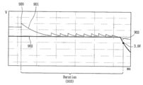
5 is a graph showing the generation of peak voltage when the battery is separated from the conventional vacuum cleaner, and FIG. 6 is a suction motor without generating a peak voltage when the battery is removed while the suction motor is being driven in the vacuum cleaner according to an embodiment of the present invention. It is a graph showing that the operation is stopped.
7 is a graph showing the waveform of the pulse width modulation (PWM) signal associated with FIG. 5, and FIG. 8 is a graph showing the waveform of the PWM signal associated with FIG. 6.
9A and 9B are graphs for explaining a time during which the application of power to the control unit is maintained when the battery is removed while the suction motor is driven in the vacuum cleaner according to an embodiment of the present invention.
이하, 첨부된 도면을 참조하여 본 명세서에 개시된 실시 예를 상세히 설명하되, 도면 부호에 관계없이 동일하거나 유사한 구성요소에는 동일한 참조 번호를 부여하고 이에 대한 중복되는 설명은 생략하기로 한다. 또한, 첨부된 도면은 본 명세서에 개시된 실시 예를 쉽게 이해할 수 있도록 하기 위한 것일 뿐, 첨부된 도면에 의해 본 명세서에 개시된 기술적 사상이 제한되지 않으며, 본 발명의 사상 및 기술 범위에 포함되는 모든 변경, 균등물 내지 대체물을 포함하는 것으로 이해되어야 한다. Hereinafter, exemplary embodiments disclosed herein will be described in detail with reference to the accompanying drawings, but the same reference numerals will be assigned to the same or similar elements regardless of reference numerals, and redundant descriptions thereof will be omitted. In addition, the accompanying drawings are only for easy understanding of the embodiments disclosed in the present specification, and the technical spirit disclosed in the specification is not limited by the accompanying drawings, and all modifications included in the spirit and technical scope of the present invention , It should be understood to include equivalents or substitutes.
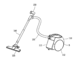
도 1a 및 도 1b 본 발명에 따른 진공 청소기, 예를 들어 스틱 청소기와 스틱 청소기로부터 배터리 어셈블리가 분리되는 것을 보여준다. 1A and 1B show that the battery assembly is separated from a vacuum cleaner according to the present invention, for example a stick cleaner and a stick cleaner.
도 1a를 참조하면, 스틱 청소기(100)는 흡입력을 발생시키기 위한 흡입 모터를 내측에 구비하는 청소기 본체(10)와, 먼지가 포함된 공기를 흡입하는 흡입부(120) 및 상기 청소기 본체(10)와 상기 흡입부(120)를 연결하는 연장관(17)을 포함할 수 있다.Referring to FIG. 1A, the
도시되지 않았으나, 상기 흡입부(120)는 상기 연장관(17) 없이도 상기 청소기 본체(10)에 직접 연결될 수도 있다.Although not shown, the
상기 청소기 본체(10)는 공기에서 분리된 먼지가 저장되는 먼지통(12)을 포함할 수 있다. 이에 따라, 상기 흡입부(20)을 통해 유입되는 먼지는 상기 연장관(17)을 통해 상기 먼지통(12)에 저장될 수 있다.The
상기 청소기 본체(10)의 외측에는 사용자가 파지하기 위한 핸들(13)이 구비될 수 있다. 사용자는 상기 핸들(13)을 파지한 상태로 청소를 수행할 수 있다.A
상기 청소기 본체(10)에는 충전가능한 배터리(미도시)를 포함한 배터리 어셈블리가 장착될 수 있다. 이를 위해, 상기 청소기 본체(10)에는 상기 배터리가 수용되는 배터리 수용부(15)가 구비될 수 있다. 예를 들어, 상기 배터리 수용부(15)는 핸들(13)의 하부에 구비될 수 있다. A battery assembly including a rechargeable battery (not shown) may be mounted on the
상기 배터리 어셈블리에 포함된 배터리는 상기 흡입부(120)과 연결되어 상기 흡입부(100)로 전원을 공급할 수 있다. 또, 상기 배터리는 본체(10)에 내장되어 흡입력을 발생시키는 흡입 모터(미도시)에 전원을 공급한다. The battery included in the battery assembly may be connected to the
한편, 입력부(110)는 청소기 본체(10)를 전원 온(off) 또는 오프(off)시키기 위한 사용자 입력을 수신할 수 있다. 또, 상기 입력부(110)는 청소의 수행에 따라 흡입 모터(미도시)가 구동되는 동안 흡입 모터의 파워 레벨을 조절하기 위한 사용자 입력을 수신할 수 있다. 또, 상기 입력부(110)는 기설정된 다양한 청소 동작모드를 설정, 변경하기 위한 사용자 입력을 수신할 수 있다. Meanwhile, the
한편, 배터리 수용부(15)에 장착된 배터리 어셈블리(190)는 도 1b에 도시된 바와 같이 배터리 수용부(15)의 바닥면 방향으로 인출될 수 있다. 이에 의하여, 배터리 어셈블리(190)가 청소기 본체로부터 분리될 수 있다. 배터리 어셈블리(190)는 배터리의 충전이 필요한 경우 사용자 조작에 의해 청소기 본체로부터 분리될 수 있다. 또는, 배터리 어셈블리(190)가 배터리 수용부(15)에 불안정하게 안착된 경우 또는 지지수단의 고장 등으로 인해 비의도적으로 청소기 본체로부터 분리될 수 있다.Meanwhile, the
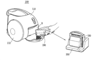
도 2a, 도 2b는 본 발명의 실시 예에 따른 또 다른 진공 청소기, 예를 들어 캐니스터 청소기와 캐니스터 청소기로부터 배터리 어셈블리가 분리되는 것을 보여준다. 2A and 2B show that the battery assembly is separated from another vacuum cleaner, for example, a canister cleaner and a canister cleaner according to an embodiment of the present invention.
도 2a를 참조하면, 진공 청소기는 플렉시블 호스(150)를 통하여, 흡입부(120) 및 연장관(140)과 청소기 본체(110)가 연결되는 구조로 이루어질 수 있다. 즉, 청소기 본체(110)와 흡입부(120)가 별도로 분리된 구조를 취한다. 사용자는 핸들(130)을 파지한 상태로 흡입부(120)의 이동방향을 조작할 수 있다. 흡입부(120)와 분리된 청소기 본체는 사용자의 핸들(130) 조작에 따라 플렉시블 호스(150)가 당겨지는 방향으로 주행부(111, 112)를 이동/회전하여 움직인다. 청소기 본체(110)의 후방부에는 배터리 어셈블리가 안착된 배터리 수용공간(B)이 마련될 수 있다. Referring to FIG. 2A, the vacuum cleaner may be formed of a structure in which the
도 2b를 참조하면, 배터리 수용공간(B)의 외측에는 도어가 마련될 수 있다. 사용자 조작에 따라 상기 도어가 열리면, 배터리 수용공간(B)이 노출된다. 노출된 배터리 수용공간(B)에는 배터리 어셈블리(190)가 인입되거나 또는 인출될 수 있다. 배터리 어셈블리(190)가 배터리 수용공간(B)으로부터 인출된 경우 배터리가 청소기 본체(110)로부터 분리되었다고 말할 수 있다.Referring to FIG. 2B, a door may be provided outside the battery accommodating space B. When the door is opened according to user manipulation, the battery accommodating space B is exposed. The
배터리 어셈블리(190)는 배터리의 충전이 필요한 경우 사용자 조작에 의해 배터리 수용공간(B)로부터 꺼내질 수 있다. 또, 배터리 수용공간(B)의 도어가 제대로 닫히지 않은 상태에서 청소기의 작동에 따라 본체가 이동하는 경우 비의도적으로 청소기 본체로부터 인출될 수도 있다.The
본 발명에서는, 청소기 작동 중에 비의도적으로 배터리가 분리되거나 또는 실수로 전원을 끄지 않고 배터리를 의도적으로 분리시킨 경우, 이러한 배터리 분리를 감지하여, 인버터 회로의 소손을 방지하기 위한 방법을 구현하였다. In the present invention, when the battery is unintentionally disconnected during operation of the cleaner or the battery is intentionally disconnected without accidentally turning off the power, a method for preventing damage to the inverter circuit by detecting such battery disconnection has been implemented.
배터리를 사용하는 진공 청소기의 경우 청소기 작동 중에 배터리가 분리되면 흡입 모터의 구동이 중단된다. 그러나, 흡입 모터가 빠르게 회전하는 도중 갑자기 배터리가 분리되면, 작동중인 흡입 모터에서 발생되는 역기전력과 인버터 회로의 DC 단 커패시터의 충전 전압이 더해져서 피크(peak), 즉 과전압이 발생하게 된다. 이러한 과전압은 인버터 등 부품 소손의 위험성을 높인다.In the case of a vacuum cleaner using a battery, if the battery is disconnected during the operation of the cleaner, the suction motor stops operating. However, if the battery is suddenly disconnected while the suction motor is rapidly rotating, the back EMF generated in the active suction motor and the charging voltage of the DC terminal capacitor of the inverter circuit are added to generate a peak, that is, an overvoltage. This overvoltage increases the risk of component burnout, such as inverters.
본 발명에서는 이러한 피크 발생에 따른 인버터 회로의 부품 소손을 방지하기 위해, 청소기가 작동하는 동안 배터리의 분리를 쉽게 감지하고, 배터리가 분리된 것으로 감지되면 인버터 회로의 스위치에 대한 PWM(Pulse Width Modulation) 듀티 사이크을 조정함으로써, 급작스런 배터리 분리시에도 인버터 회로의 소손이 발생하지 않도록 구현하였다. In the present invention, in order to prevent component burnout of the inverter circuit due to the occurrence of such a peak, it is easy to detect the disconnection of the battery while the cleaner is operating, and if the battery is detected to be disconnected, PWM (Pulse Width Modulation) for the switch of the inverter circuit By adjusting the duty cycle, the inverter circuit is not burned out even when the battery is suddenly disconnected.
구체적으로, 본 발명에 따른 진공 청소기는, 본체에 장착되어, 흡입력을 발생시키는 흡입모터에 전압을 공급하는 배터리가 포함된 배터리 어셈블리와; 배터리로부터 제공되는 공급 전압을 흡입모터에 연결하는 스위치를 포함하는 인버터와; 흡입모터가 구동되는 동안 배터리 어셈블리가 청소기 본체로부터 분리된 것을 감지하고, 스위치에 연결된 커패시터에 충전된 전압을 이용하여 흡입 모터가 감속 구동 되도록 스위치를 제어하기 위한 PWM 신호를 출력하는 제어부를 포함한다. 이에 의하면, 청소기 작동 중에 배터리가 분리되더라도, 과전압의 발생 없이 흡입 모터의 구동이 정지될 수 있다. Specifically, the vacuum cleaner according to the present invention is mounted on the body, the battery assembly including a battery for supplying a voltage to the suction motor for generating a suction force; An inverter including a switch for connecting the supply voltage provided from the battery to the suction motor; It includes a control unit that detects that the battery assembly is separated from the cleaner body while the suction motor is driven, and outputs a PWM signal for controlling the switch so that the suction motor is decelerated by using a voltage charged in a capacitor connected to the switch. According to this, even if the battery is removed during the operation of the cleaner, the driving of the suction motor may be stopped without generating overvoltage.
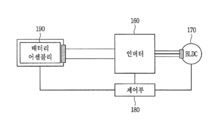
도 3a은 청소기에 장착된 배터리 어셈블리의 배터리로부터 제공된 공급 전압이 인버터 회로(160)를 거쳐 흡입 모터(170), 예를 들어 BLDC 모터에 전달되는 과정을 보여주는 블록도이다. 한편, 이하에 개시된 BLDC 모터는 흡입 모터(170)로 이해될 수 있다. 그러나, 본 발명에 따른 흡입 모터(170)가 반드시 BLDC 모터로 제한되는 것을 의미하는 것은 아니며, 본 발명과 모순되지 않는 범위에서, 상기 흡입 모터(170)는 브러쉬형 모터를 포함하는 것으로 해석될 수 있을 것이다. 3A is a block diagram showing a process in which a supply voltage provided from a battery of a battery assembly mounted on a cleaner is transferred to an
BLDC 모터는 브러쉬가 없기 때문에, u, v, w 3상 각각을 勵磁(여자, 전류가 통하는 상태) 시켜서 자계를 형성하는 방식으로 흡입 모터가 회전된다. 또, BLDC 모터는 스테이터가 코일로 이루어지고 중앙의 로터가 영구자석으로 이루어진다. BLDC 모터의 회전속도는 상기 로터의 위치를 검출하여 획득될 수 있다. Since the BLDC motor does not have a brush, the suction motor is rotated in such a way that the three phases of u, v, and w are turned to each other (excitation, current is applied) to form a magnetic field. In addition, in the BLDC motor, the stator is made of a coil and the center rotor is made of a permanent magnet. The rotational speed of the BLDC motor can be obtained by detecting the position of the rotor.
배터리 어셈블리(190)는 청소기 동작시 흡입 모터에 전압을 공급하는 배터리를 포함한다. 배터리 어셈블리(190)는 다수의 셀(cells)로 구성된 배터리의 안정성 확보와 밸런싱 유지를 위한 BMS(Battery Management System, 이하) 회로를 더 포함할 수 있다. The
배터리에 충전된 전압은, BMS의 제어에 따라, 파워 라인(Power line)을 통해 인버터 스위치(160)의 입력단에 공급 전압으로서 제공된다. 또, 상기 공급 전압은 예를 들어 25V의 크기를 가질 수 있으며, 최대 30V(또는, 29.4V)의 크기일 수 있다.The voltage charged in the battery is provided as a supply voltage to the input terminal of the
파워 라인(Power line)에는 공급 전압의 크기를 감지하기 위한 전압 검출 수단, 예를 들어 전압 센서가 연결될 수 있다. 또 다른 예에서는, 전압 센서가 인버터(160)의 출력단에 연결되어, 흡입 모터(170)에 인가되는 공급 전압을 검출할 수 있다.A voltage detection means for detecting the magnitude of the supply voltage, for example, a voltage sensor, may be connected to the power line. In another example, a voltage sensor is connected to the output terminal of the
인버터(160)는 배터리 어셈블리(190)의 배터리로부터 제공되는 공급 전압을 흡입 모터(170)에 연결한다. 또, 인버터(160)는 BLDC 모터의 3상에 각각 공급 전압을 제공할 수 있도록, 3상 인버터로 구현될 수 있다. The
제어부(180)는 배터리 어셈블리(190), 인버터(160), 및 흡입 모터(170)의 동작을 제어할 수 있고, 이를 위해 제어신호를 출력할 수 있다. 또한, 본 발명에서 상기 제어부(180)는 스위치 제어수단 또는 PWM 모듈을 의미할 수 있다. The
이러한 경우, 상기 제어부(180)는 인버터(160)에 PWM 신호를 출력하거나, 또는 이를 위해 인버터(160)와 연결된 MOSFET(미도시)에 게이트 신호를 출력할 수 있다.In this case, the
청소기가 정상적으로 작동되는 상태에서, 배터리 어셈블리(190)의 배터리로부터 제공되는 공급 전압은, BLDC 모터의 회전속도가 목표 회전속도에 도달하도록, 제어된다. In a state in which the cleaner is normally operated, the supply voltage provided from the battery of the
구체적으로, 제어부(180)에 의해 출력된 PWM 신호가 인버터(160) 또는 인버터와 연결된 MOSFET(미도시)의 게이트에 전달되면, BLDC 모터는 주기적으로 스위치 온(on)된다. 이때, 상기 PWM 신호의 듀티 사이클이 커질수록 BLDC 모터에 인가되는 전력(W)의 크기는 대응되게 증가된다. 이제, BLDC 모터의 회전속도가 목표 회전속도에 도달되면, 전력 제어를 위해, 모터의 감속 구동이 수행되어야할 것이다. 이를 위해, 제어부(180)는 PWM 신호의 듀티 사이클을 감소시켜서 BLDC 모터에 인가되는 전력(W)의 크기를 대응되게 감소시킬 수 있다. 청소기가 작동되는 동안 이와 같은 과정이 반복된다. Specifically, when the PWM signal output by the
한편, 위와 같은 청소기 작동 중 배터리 어셈블리(190)가 청소기 본체로부터 분리되면, 배터리 어셈블리(190)의 분리에 따른 공급 전압의 크기 변화와 흡입모터의 회전 속도의 변화에 대응하여 상기 PWM 신호의 듀티 사이클이 다르게 조정된다. 이를 보다 구체적으로 설명하기 위해 도 3b에 도시된 인버터 회로를 참조하기로 한다. On the other hand, if the
도 3b에 도시된 바와 같이 인버터 회로는, 공급 전압이 평활되고 충전되는 DC 단 커패시터(330)와 3 쌍의 상하단 스위칭 소자들(310, 320)를 구비한 3상 인버터를 포함하여 이루어진다. 3 쌍의 상하단 스위칭 소자들(310, 320)은 iGBT (Insulated Gate Bipolar Transistor), MOSFET 및 BJT 중 적어도 하나의 소자를 사용하여 구현될 수 있다. As shown in Figure 3b, the inverter circuit comprises a three-phase inverter having a
도시된 인버터 회로에서, DC 단 커패시터(330)를 통해 제공된 공급 전압은 상단 스위칭 소자(310)와 하단 스위칭 소자(320)를 거쳐 BLDC 모터에 제공된다. 이때, 미리 설정된 또는 흡입 모터의 회전속도에 따라 산출된 듀티 사이클에 대응되는 PWM 신호가, 상기 상하단 스위칭 소자들(310, 320)에 출력됨으로써, 상하단 스위칭 소자들(310, 320)이 고속으로 스위칭 온오프(on/off) 된다.In the illustrated inverter circuit, the supply voltage provided through the DC
한편, 청소기 작동 중에 배터리 어셈블리(190)가 청소기 본체로부터 분리되면, 인버터 회로의 상단 스위칭 소자(310)가 모두 오프되어, 오프(off) 상태가 된다. 그리고, 하단 스위칭 소자(320)는 오프(off)되지 않고 공급 전압 대비 약 1% 범위 내외의 정해진 듀티 사이클로 PWM 제어된다. On the other hand, if the
예를 들어, 배터리의 공급 전압이 25V 라면, 배터리 분리 후 25V 대비 1% 듀티 사이클로 하단 스위칭 소자(320)가 온오프 제어된다. 또, 예를 들어, 배터리의 공급 전압이 30V 라면, 배터리 분리 후 30V 대비 1% 듀티 사이클로 하단 스위칭 소자(320)가 온오프 제어된다.For example, if the supply voltage of the battery is 25V, the
따라서, 하단 스위칭 소자(320)에 출력되는 PWM 신호의 듀티 사이클이 1% 내외라 함은, 정상 상태에서 하단 스위칭 소자(320)에 출력되었던 PWM 신호의 듀티 사이클 보다 작은 양으로 출력되는 것을 의미한다. 따라서, 하단 스위칭 소자(320)에 출력되는 PWM의 듀티 사이클이 반드시 1%로 제한됨을 의미하는 것은 아니다. Accordingly, that the duty cycle of the PWM signal output to the
일단 배터리 어셈블리가 청소기 본체로부터 분리되면, 제어부(180)는 인버터 회로의 상단 스위칭 소자(310)에 오프 상태로 전환하는 제1제어신호/제1게이트 신호를 출력하고, 하단 스위칭 소자(320)는 보다 감소된 양의 듀티 사이클로 PWM 제어를 수행하기 위한 제2제어신호/제2게이트 신호를 출력할 수 있다. Once the battery assembly is separated from the cleaner body, the
또한, 하단 스위칭 소자(320)에 출력되는 PWM 신호의 듀티 사이클이 1% 내외라 함은, 입력 전압의 크기에 따라 듀티 사이클의 양이 조정되는 것이 아니라 고정범위/고정값의 듀티 사이클로 PWM 신호가 출력되는 것을 의미한다. In addition, when the duty cycle of the PWM signal output to the
따라서, 공급 전압의 크기에 따라 듀티 사이클의 양이 가변되지 않고, 인버터 회로의 하단 스위칭 소자(320)에 대해서는 고정범위/고정값의 듀티 사이클, 예를 들어 1% 내외로 감소된 듀티 사이클로 PWM 신호가 출력된다. Therefore, the amount of the duty cycle does not vary depending on the magnitude of the supply voltage, and the PWM signal with a duty cycle of a fixed range / fixed value, for example, a duty cycle reduced to about 1%, for the
이와 같이, 청소기의 제어부(180)는 배터리 어셈블리(190)가 청소기 본체로부터 분리된 것이 감지되면, 인버터 회로 내 하단 스위칭 소자에 대한 PWM 신호의 듀티 사이클을 배터리 어셈블리(190)가 분리되기 전보다 작은 양으로 조정한다. As described above, when the
예를 들어, 배터리 어셈블리(190)가 분리되기 전에 수행되던 듀티 사이클이 10% 인 경우, 배터리 어셈블리(190)의 분리 후에는 약 1/10 감소된 1% 듀티 사이클로 PWM 신호가 출력된다. 또, 정상 상태에서 15%의 듀티 사이클로 PWM 신호가 출력되었다면 배터리 어셈블리(190)의 분리 후에는 약 1/10 감소된 1.5% 듀티 사이클로 PWM 신호가 출력된다.For example, when the duty cycle performed before the
이와 같이 배터리 분리 후, 인버터 회로의 하단 스위칭 소자(320)에 대한 PWM 제어를 통해 모터에 상 전류(ias, ibs, ics)가 공급됨으로써, 역기전력에 의한 과전압 없이, DC 단 커패시터(330)측에서 BLDC 모터측 방향으로 여자된다. After the battery is separated, the phase currents (ias, ibs, ics) are supplied to the motor through PWM control of the
이상에서 살펴본 바와 같이, 본 발명에 의하면, 청소기 작동 중 배터리 분리시 인버터의 하단 스위칭 소자에 대해서만 PWM 듀티 사이클을 입력전압 대비 정해진 값으로 제어한다. 그에 따라, 경제적으로, 흡입 모터에서 발생된 역기전력에 의한 과전압 발생으로 인한 인버터의 부품 소손을 방지할 수 있다.As described above, according to the present invention, when the battery is removed during the operation of the cleaner, only the lower switching element of the inverter controls the PWM duty cycle to a predetermined value compared to the input voltage. Accordingly, economically, it is possible to prevent component damage of the inverter due to overvoltage generated by back EMF generated in the suction motor.
도 4a와 도 4b는 본 발명에 따른 진공 청소기의 제어방법의 흐름도들이다.4A and 4B are flowcharts of a control method of a vacuum cleaner according to the present invention.
먼저 도 4a를 참조하면, 청소기 작동에 따라 청소기 본체(110)에 구비된 흡입 모터가 구동되는 과정이 개시된다(S10). 예를 들어, 청소기가 전원 온(on) 되어 작동되면, 흡입 모터가 구동된다. Referring first to FIG. 4A, a process in which the suction motor provided in the
흡입 모터가 구동하는 동안, 청소기 본체에 장착된 배터리 어셈블리가 분리되는 것을 감지하는 과정이 수행된다(S20). 배터리 어셈블리가 청소기 본체로부터 분리되었는지 여부는, 공급 전압의 크기와 흡입 모터의 회전속도를 모니터링하여 감지할 수 있다. 여기서, 공급 전압의 크기는 배터리 어셈블리의 출력단 또는 인버터 회로의 입력단에 전압 센서를 추가하여 획득될 수 있다. 또, 흡입 모터의 회전속도는 흡입 모터에 공급되는 상 전류를 검출하는 전류 센서 및/또는 흡입 모터의 회전자 위치를 검출하는 위치 센서를 통해 획득될 수 있다. While the suction motor is driven, a process of detecting that the battery assembly mounted on the cleaner body is separated is performed (S20). Whether the battery assembly is separated from the cleaner body can be detected by monitoring the magnitude of the supply voltage and the rotational speed of the suction motor. Here, the magnitude of the supply voltage can be obtained by adding a voltage sensor to the output terminal of the battery assembly or the input terminal of the inverter circuit. In addition, the rotational speed of the suction motor can be obtained through a current sensor that detects the phase current supplied to the suction motor and / or a position sensor that detects the rotor position of the suction motor.
공급 전압의 크기가 소정 값 미만이면서 흡입 모터의 회전속도가 정상 회전 속도이면, 청소기 작동 중에 배터리 어셈블리가 분리된 것으로 감지된다. 배터리 어셈블리의 분리로 감지되기 위한 공급 전압의 크기와 흡입 모터의 회전속도에 대해서는 이하 도 4b에서 더 구체적으로 설명하겠다. If the magnitude of the supply voltage is less than a predetermined value and the rotation speed of the suction motor is a normal rotation speed, it is detected that the battery assembly is disconnected during the operation of the cleaner. The size of the supply voltage and the rotational speed of the suction motor to be detected by the separation of the battery assembly will be described in more detail in FIG. 4B.
배터리 어셈블리가 분리된 것이 감지되면, 인버터와 연결된 커패시터에 충전되어 있던 전압을 이용하여 흡입 모터가 감속 구동되도록 스위칭 신호, 즉 PWM 신호를 출력하는 과정을 수행한다(S30). When it is detected that the battery assembly is disconnected, a process of outputting a switching signal, that is, a PWM signal, is performed so that the suction motor is decelerated by using the voltage charged in the capacitor connected to the inverter (S30).
배터리 어셈블리의 분리시, 감속 구동을 위해 흡입 모터에서 발생되는 역기전력과 커패시터에 충전된 충전 전압이 더해져서 피크(peak) 전압, 즉 과전압을 발생시킨다. 예를 들어, 배터리에 의한 공급 전압이 25V로 제공되고 있었다면, 배터리 어셈블리의 분리가 감지된 후에는 순간적으로 약 40~50V까지 과전압이 발생된다. 이러한 순간적인 과전압은 인버터 회로의 소손을 야기한다.When the battery assembly is separated, the back electromotive force generated in the suction motor and the charging voltage charged in the capacitor are added for deceleration driving to generate a peak voltage, that is, an overvoltage. For example, if the supply voltage by the battery was provided at 25V, after the separation of the battery assembly is detected, an overvoltage is generated up to about 40-50V instantaneously. This instantaneous overvoltage causes damage to the inverter circuit.
이에, 본 발명에서는 배터리 어셈블리의 분리시, 인버터 회로의 상단 스위칭 소자는 모두 오픈시켜서 오프(off) 상태로 제어하기 위한 게이트 신호를 출력하고, 인버터 회로의 하단 스위칭 소자는 PWM 신호의 듀티 사이클을 감소시키는 제어신호/게이트 신호를 출력한다. 그에 따라, 배터리 어셈블리의 분리가 감지된 후에도 최대 전압의 크기가 공급 전압, 예를 들어 25V 까지만 발생된다.Accordingly, in the present invention, when the battery assembly is disconnected, all of the upper switching elements of the inverter circuit are opened to output a gate signal for controlling in an off state, and the lower switching elements of the inverter circuit reduce the duty cycle of the PWM signal. The control signal / gate signal is output. Accordingly, even after the separation of the battery assembly is sensed, the magnitude of the maximum voltage is generated only up to the supply voltage, for example, 25V.
다음, 도 4b를 참조하여 청소기 작동 중 배터리 어셈블리의 분리를 감지하는 방법과 그에 따라 인버터 회로를 제어하는 방법을 보다 구체적으로 살펴보겠다.Next, with reference to FIG. 4B, a method of detecting separation of the battery assembly during operation of the cleaner and a method of controlling the inverter circuit accordingly will be described in more detail.
청소기의 전원이 온(on) 상태가 되면 청소기가 작동된다. 그에 따라, 청소기의 제어부(180)는 흡입 모터가 구동 중인지를 파악한다(S410). 흡입 모터가 구동 중인 동안, 배터리 어셈블리가 본체로부터 분리되는지를 파악하기 위해, 배터리의 공급 전압의 크기와 흡입 모터의 회전속도를 지속적으로 모니터링한다.When the power of the vacuum cleaner is turned on, the vacuum cleaner is operated. Accordingly, the
배터리의 공급 전압의 크기는 배터리 어셈블리에 포함된 배터리의 출력단 또는 배터리와 연결된 인버터 회로의 입력단에 흐르는 전압을 감지하여 확인할 수 있다. 이를 위해, 배터리의 출력단 또는 인버터 회로의 입력단에는 전압 센서(미도시)가 구비될 수 있다. 이와 같이 전압 센서 등에 의해 감지된 공급 전압의 크기는 '배터리 감지전압'으로 명명될 수 있다. 또, 흡입 모터의 회전속도는 전술한 바와 같이 흡입 모터에 공급되는 상 전류를 검출하는 전류 센서 및/또는 흡입 모터의 회전자 위치를 검출하는 위치 센서를 통해 획득될 수 있다.The size of the supply voltage of the battery can be confirmed by sensing the voltage flowing to the output terminal of the battery included in the battery assembly or the input terminal of the inverter circuit connected to the battery. To this end, a voltage sensor (not shown) may be provided at the output terminal of the battery or the input terminal of the inverter circuit. The magnitude of the supply voltage sensed by the voltage sensor may be referred to as a 'battery detection voltage'. In addition, the rotational speed of the suction motor can be obtained through a current sensor that detects the phase current supplied to the suction motor and / or a position sensor that detects the rotor position of the suction motor.
이와 같은 배터리의 감지전압과 흡입 모터의 회전속도의 모니터링에 따라, 배터리 감지전압이 제1기준값 이하이고 흡입 모터의 회전속도가 제2기준값 이상이면, 청소기 작동 중의 배터리 분리로 보고 단계 S440 과정에 따라 인버터 회로가 제어된다. According to the monitoring of the detection voltage of the battery and the rotational speed of the suction motor, if the battery detection voltage is less than the first reference value and the rotational speed of the suction motor is greater than or equal to the second reference value, the battery is reported to be separated during operation of the cleaner and according to step S440. The inverter circuit is controlled.
구체적으로, 배터리 감지전압이 제1기준값 이하이면서 흡입 모터의 회전속도는 제2기준값 이상이면(S420), 청소기 작동 중에 배터리가 분리된 것으로 판단한다. Specifically, if the battery detection voltage is less than the first reference value and the rotational speed of the suction motor is greater than or equal to the second reference value (S420), it is determined that the battery is disconnected during the operation of the cleaner.
여기에서, 제1기준값은 충전된 배터리(충전된 배터리가 방전되기 전을 포함할 수 있음)가 청소기 본체에 장착된 경우에 제공되는 최소전압을 의미할 수 있다. 예를 들어, 입력전압이 25V일 때 상기 제1기준값은 약 18V 값일 수 있다. Here, the first reference value may mean the minimum voltage provided when the charged battery (which may include before the charged battery is discharged) is mounted on the cleaner body. For example, when the input voltage is 25V, the first reference value may be about 18V.
또, 상기 제2기준값은 청소기가 정상적으로 작동하는 경우에 구동되는 흡입 모터의 평균 회전속도 또는 최소 회전속도를 의미할 수 있다. 예를 들어, 상기 제2기준값은 6000~6600rpm 중 임의값일 수 있다. In addition, the second reference value may mean an average rotational speed or a minimum rotational speed of the suction motor driven when the cleaner operates normally. For example, the second reference value may be any value from 6000 to 6600 rpm.
단계 S440 에서는, 인버터 내 스위치와 연결된 DC 단 커패시터에 충전된 충전 전압을 이용하여, 상기 스위치의 하단 스위칭 소자가 고속 스위칭된다. 이때에, 상기 하단 스위칭 소자에 대한 PWM 신호의 듀티 사이클은 공급 전압 대비 약 1% 내외로 출력된다. 이는, 배터리 분리전 듀티 사이클 보다 감소된 듀티 사이클로 운영되는 것이며, DC 단 커패시터에 충전된 전압이 방전될 때까지 수행된다. 커패시터에 충전된 전압이 방전되면, 청소기의 제어부(180)는 인버터 회로 내 상단 스위칭 소자는 오프 상태를 유지하고, 하단 스위칭 소자는 온 상태로 제어하여, 흡입 모터의 구동을 정지시킬 수 있다. In step S440, the lower switching element of the switch is switched at high speed using a charging voltage charged in a DC terminal capacitor connected to a switch in the inverter. At this time, the duty cycle of the PWM signal for the lower switching element is output in about 1% of the supply voltage. This is operated with a reduced duty cycle than the duty cycle before battery separation, and is performed until the voltage charged in the DC stage capacitor is discharged. When the voltage charged in the capacitor is discharged, the
한편, 본 발명에서는 청소기 작동 중에 공급 전압의 크기와 흡입 모터의 회전속도를 지속적으로 모니터링하여, 배터리 어셈블리가 청소기 본체로부터 분리되었는지 여부를 스스로 감지할 수 있다. 이를 위해, 공급 전압의 크기를 감지하기 위한 전압 검출 수단(예, 전압 센서)과 흡입모터의 회전 속도를 감지하기 위한 속도 검출 수단(예, 위치 센서 및/또는 전류 센서)이 구비될 수 있다. Meanwhile, in the present invention, the size of the supply voltage and the rotational speed of the suction motor are continuously monitored during the operation of the cleaner, so that the battery assembly can be detected by itself. To this end, voltage detecting means (eg, a voltage sensor) for detecting the magnitude of the supply voltage and speed detecting means (eg, a position sensor and / or a current sensor) for sensing the rotational speed of the suction motor may be provided.
제어부(180)는 이러한 전압 검출 수단에 의해 감지된 공급 전압의 크기가 상기 제1 기준값 이하이고 속도 검출 수단에 의해 감지된 회전 속도가 상기 제2 기준값 이상이면, 상기 배터리 어셈블리가 상기 본체로부터 분리된 것으로 감지한다. When the magnitude of the supply voltage sensed by the voltage detecting means is less than the first reference value and the rotational speed sensed by the speed detecting means is greater than or equal to the second reference value, the
반면, 상기 전압 검출 수단에 의해 감지된 공급 전압의 크기가 제1 기준값을 초과하거나 그리고/또는 상기 속도 검출 수단에 의해 감지된 회전 속도가 제2 기준값 미만이면, 제어부(180)는 배터리 어셈블리가 청소기 본체로부터 분리되지 않은 것으로 판단할 수 있다.On the other hand, if the magnitude of the supply voltage sensed by the voltage detecting means exceeds a first reference value and / or the rotational speed sensed by the speed detecting means is less than a second reference value, the
일 실시 예에서는, 청소기 작동 중 청소기 본체로부터 배터리가 분리되었는지 여부를 또 다른 센서, 예를 들어 탈장착 버튼의 조작에 따른 스위칭 신호의 발생을 감지하는 스위칭 센서 등을 통해 감지할 수도 있다. 그리고, 배터리 분리가 감지되면, 배터리 분리를 나타내는 기정해진 신호음, LED, 이미지, 음성 등이 출력될 수도 있다.In an embodiment, whether the battery is removed from the cleaner body during the operation of the cleaner may be detected through another sensor, for example, a switching sensor that detects the occurrence of a switching signal according to the operation of the detachable button. In addition, when battery separation is detected, a predetermined tone, LED, image, voice, etc. indicating battery separation may be output.
배터리가 분리된 것으로 판단되지 않으면서 흡입 모터의 회전속도가 상기 제2기준값 미만이면(S430), 흡입 모터의 구동을 중단시키기 위해 단계 S450 과정에 따라 인버터 회로가 제어된다. 이때는, 예를 들어 비정상 상태로 청소기가 작동 중인 것으로 보거나 또는 청소기의 전원이 오프(off)된 것으로 볼 수 있다. If the rotation speed of the suction motor is less than the second reference value without determining that the battery is separated (S430), the inverter circuit is controlled according to step S450 to stop driving the suction motor. At this time, for example, it may be considered that the cleaner is operating in an abnormal state or that the power of the cleaner is turned off.
단계 S450에서는, 인버터 회로 내 상단 스위칭 소자를 오픈하여 오프 상태(off)로 제어하기 위한 게이트 신호와 하단 스위칭 소자를 PWM 제어 대신 온(on) 상태로 제어하기 위한 게이트 신호를 출력한다. 그에 따라, 흡입 모터가 완전히 구동 정지된다. In step S450, the upper switching element in the inverter circuit is opened to output a gate signal for controlling the off state (off) and the lower switching element for controlling the on state instead of PWM control. Accordingly, the suction motor is completely stopped.
한편, 단계 S430의 판단 결과, 배터리 감지전압이 상기 제1기준값을 초과하면서 흡입 모터의 회전속도가 상기 제2기준값 이상이면, 청소기가 정상적으로 작동 중인 것으로 보고, 단계 S460에 따라 인버터 회로를 제어한다.On the other hand, as a result of the determination in step S430, if the battery detection voltage exceeds the first reference value and the rotation speed of the suction motor is greater than or equal to the second reference value, the cleaner is considered to be operating normally, and the inverter circuit is controlled according to step S460.
단계 S460에서는 인버터 회로 내 상하단 스위칭 소자에 대해 모두 PWM 제어가 수행된다. 구체적으로, 배터리로부터 제공되는 입력 전압의 크기와 흡입 모터의 회전속도(청소 동작 모드에 따른 회전속도의 변화를 포함함)의 변화에 대응되는 듀티 사이클을 적용하여 PWM 제어를 수행하기 위한 게이트 신호를 출력한다.In step S460, PWM control is performed on both upper and lower switching elements in the inverter circuit. Specifically, a gate signal for performing PWM control by applying a duty cycle corresponding to a change in the magnitude of the input voltage provided from the battery and the rotational speed of the suction motor (including the change in rotational speed according to the cleaning operation mode) Output.
이하, 표 1은, 위에서 설명한 바에 따라 배터리 분리 상태와 흡입 모터의 상태에 따른 인버터 상하단 스위칭 소자의 제어를 보인 것이다.Hereinafter, Table 1 shows control of the upper and lower switching elements of the inverter according to the state of the battery separation and the state of the suction motor as described above.
표 1에서 확인할 수 있듯이, 청소기 본체로부터 배터리 분리가 감지되면, 인버터 회로 내의 상단 스위치는 흡입 모터의 구동 정지와 마찬가지로 오프(off) 상태로 제어된다. 그러나, 인버터 회로 내 하단 스위치는 정상 상태에서의 청소기 작동과 마찬가지로 PWM 제어에 따라 고속 스위칭된다. 이때, 배터리 분리가 감지된 후 인버터 회로 내 하단 스위치에 대한 PWM 신호의 듀티 사이클은, 배터리 분리 전 대비 약 1/10로 감소된 양으로 조정될 수 있다. As can be seen in Table 1, when battery separation is detected from the cleaner body, the upper switch in the inverter circuit is controlled to be off in the same manner as the suction motor is stopped. However, the lower switch in the inverter circuit is switched at high speed according to the PWM control as in the normal operation of the vacuum cleaner. At this time, the duty cycle of the PWM signal for the lower switch in the inverter circuit after the battery disconnection is detected may be adjusted to a reduced amount to about 1/10 compared to before the battery disconnection.
이하, 도 5는 기존의 진공 청소기에서 배터리 분리시 피크 전압의 발생을 보여주는 그래프이고, 도 6은 본 발명의 일 실시 예에 따른 진공 청소기에서 흡입 모터의 구동 중에 배터리 분리시 과전압 발생 없이 흡입 모터의 구동이 중단되는 것을 보여주는 그래프이다. Hereinafter, FIG. 5 is a graph showing generation of peak voltage when the battery is separated from the conventional vacuum cleaner, and FIG. 6 is a suction motor without overvoltage when the battery is removed while the suction motor is being driven in the vacuum cleaner according to an embodiment of the present invention. It is a graph showing that the operation is stopped.
도 5에서 확인되는 바와 같이, 청소기의 흡입 모터가 400W 로 구동되는 상황에서, 공급전압/공급전류(501a)는 일정범위 값을 유지하고 배터리 감지전압(502a) 또한 일정값, 예를 들어 25V로 출력된다. 그리고, 배터리 분리시(510), DC 단 커패시터의 충전 전압(501b)이 모터의 역기전력(상기 공급전압과 크기가 동일함)과 더해져서, 순간적으로 과전압이 발생되었다가 감소되는 형태의 출력전압(502b)이 된다. 역기전력은 회로에 전압이 걸릴 때 반대 방향으로 생기는 기전력이다. 이는, 자기장에 의해 애초의 전류 변화에 대하여 크기는 비례하고 방향만 반대인 전압이 인덕터에 걸리는 것을 의미하므로, 공급전압의 크기가 25V인 경우 역기전력의 크기고 25V가 된다. 따라서, 순간적인 과전압은 DC 단 커패시터의 충전 전압이 추가되어, 약 50V까지 상승한다고 말할 수 있다.5, in a situation in which the suction motor of the cleaner is driven at 400W, the supply voltage /
반면, 본 발명에 따르면, 도 6에 도시된 바와 같이 400W 로 구동되는 동일 상황에서, 배터리 분리전에는 도 5와 마찬가지로 공급전압/공급전류(601a)가 일정범위 값을 유지하고 배터리 감지전압(502a) 또한 일정값, 예를 들어 25V로 출력된다. 그러나, 배터리 분리시(610)에는, DC 단 커패시터의 충전 전압(601b)을 사용하여 PWM 제어가 수행됨에 따라, 과전압의 발생 없이, 시간 경과에 따라 점차적으로 감소되는 형태의 출력전압(602c)의 패턴을 보이게 된다. 그에 따라, 과전압 발생으로 인한 부품 소손의 발생 염려가 전혀 없게 된다. On the other hand, according to the present invention, in the same situation that is driven to 400W as shown in FIG. 6, before the battery is separated, the supply voltage /
한편, 비록 도시되지는 않았지만, 청소기의 흡입 모터가 470W 구동되는 조건에서도 도 5와 도 6에 도시된 것과 같은 결과가 출력된다. Meanwhile, although not shown, results as shown in FIGS. 5 and 6 are output even under the condition that the suction motor of the cleaner is driven at 470 W.
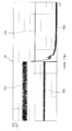
도 7은 도 5와 관련된 PWM 신호의 파형을 배터리 분리 시점을 기준으로 확장시켜서 보여주는 그래프이고, 도 8은 도 6과 관련된 PWM 신호의 파형을 배터리 분리 시점을 기준으로 확장시켜서 보여주는 그래프이다. FIG. 7 is a graph showing the waveform of the PWM signal related to FIG. 5 extended by reference to the battery separation time, and FIG. 8 is a graph showing the waveform of the PWM signal related to FIG. 6 extended by reference to the battery separation time.
도 7에서, 청소기 본체로부터 배터리가 분리되면, 상단 스위칭 소자는 오프(off) 상태가 되고, 하단 스위칭 소자는 온(on)상태가 된다. 즉, 청소기 작동 중에 배터리가 분리된 경우, 운전 정지 신호가 입력되고, 기존에는 이러한 운전 정지 신호에 따라, 하단 스위칭 소자의 PWM 신호의 듀티 사이클을 10% 에서 100%로 조정한다. In FIG. 7, when the battery is removed from the cleaner body, the upper switching element is turned off, and the lower switching element is turned on. That is, when the battery is removed during the operation of the cleaner, an operation stop signal is input, and according to the operation stop signal, the duty cycle of the PWM signal of the lower switching element is adjusted from 10% to 100%.
도 7에 도시된 바와 같이, 배터리 분리(E) 전 상하단 스위칭 소자들의 PWM 파형들(703)은, 배터리 분리(E) 후 일정 시간이 경과되면, 상단 스위칭 소자의 PWM 파형은 '0'(제로)로 수렴되고, 하단 스위칭 소자의 PWM 파형은 '1'로 수렴된다. 그리고, 배터리 감지전압(701a)은 배터리 분리(E) 후 감소되었다가(701b) 과전압(701c)으로 상승된다. 배터리 분리 후 흡입 모터에서 발생된 역기전력과 DC 단 커패시터에 충전된 전압이 더해져서 약 2배의 피크(peak) 전압이 발생된 것이다. As shown in FIG. 7, the
그러나, 본 발명에서는 도 8에 도시된 바와 같이 배터리 분리(E) 후 DC 단 커패시터를 통해 제어부(180)에 5V 전원이 인가되는 동안, 상단 스위칭 소자는 오프(off)상태로 전환되지만, 하단 스위칭 소자에는 공급 전압 대비 1% 듀티 비로 PWM 신호가 출력된다. 그에 따라, 상단 스위칭 소자의 PWM 파형은 '0'(제로)로 수렴되지만, 하단 스위칭 소자는 0, 1 의 스위칭 동작을 1% 듀티 비로 반복하여 운전된다. 여기에서, 배터리 감지전압(801a)은 배터리 분리(E) 후 감소되었다가(801b), 과전압 없이 애초의 감지전압(801a) 이하로만 상승된다. 그리고, DC 단 커패시터에 충전된 전압을 이용하여 인버터 회로의 하단 스위치가 구동되며, 그에 따라 인버터 회로의 소손없이 흡입 모터가 안전하게 감속 구동된다. However, in the present invention, while 5V power is applied to the
일 실시 예에서, 제어부(180)는 흡입 모터의 구동이 완전히 정지할 때까지 또는 커패시터가 완전히 방전될 때까지 이러한 PWM 신호 출력을 계속 수행함으로서 흡입 모터측의 역기전력 추가에 의한 피크(peak)가 발생하지 않는다.In one embodiment, the
한편, 배터리 분리 후 커피시터에 충전된 전압만으로 인버터 회로의 하단 스위칭 소자를 PWM 제어하기 위한 제어신호를 계속 출력할 수 있는지 여부가 제어부 리셋(reset) 등의 오동작과 관련하여 문제될 수 있다. 즉, 배터리 분리에 따라 DC 단 커패시터에 충전되어 있던 전압은 소정 시간 후에 방전되는데, 이 소정 시간이 본 발명에 따른 인버터 회로 내 하단 스위칭 소자의 PWM 제어를 수행하기에 충분한지 여부가 문제될 수 있다. Meanwhile, whether the control signal for PWM control of the lower switching element of the inverter circuit can be continuously output only by the voltage charged in the coffee sheet after the battery is removed may be a problem related to a malfunction such as a reset of the control unit. That is, the voltage charged in the DC stage capacitor is discharged after a predetermined time due to battery disconnection, and whether or not this predetermined time is sufficient to perform PWM control of the lower switching element in the inverter circuit according to the present invention may be a problem. .
이에, 본 발명에서는 배터리 어셈블리(190)가 청소기 본체로부터 분리된 것이 감지된 후에도, 일정 시간 동안 제어부(180)에 정격 전압이 인가된다. 이때, 정격전압 출력을 위한 5V 레귤레이터가 상기 인버터 회로와 연결될 수 있다. 제어부(180)는, 상기 정격 전압에 의해 인버터 회로 내 스위치를 제어하기 위한 PWM 신호를 출력할 수 있다. Thus, in the present invention, even after detecting that the
도 9a는 배터리 분리 후, 제어부(180), 즉 마이컴에 전원 인가가 유지되는 시간(ms)의 정규분포를 보인 것이다. 도시된 바와 같이, 유지시간(910)은 30회 반복 시험 조건에서, 484ms에 가장 많은 분포를 보이고, 평균 483.7임을 확인할 수 있다. 9A shows the normal distribution of the time (ms) in which power is maintained to the
도 9b는 배터리 분리(920) 후 DC 단 커패시터의 충전 전압의 변화와 제어부(180)에 인가되는 5V 전원의 유지시간을 보여주고 있다. 배터리 분리(920) 후 커패시터의 충전 전압은 점진적으로 감소되어 방전된다. 그에 따라, 배터리 분리(920) 후에도 5V 전원의 유지시간(910)은 약 483ms 동안 유지된다. 그리고, 커패시터의 충전 전압이 완전히 방전된 후, 즉 약 483ms 유지시간(910)이 경과된 후에야, 5V 전압이 3.9V로 감소된다. 이와 같이 배터리 분리(920) 후에도 충분한 시간 동안 5V 전압이 유지되는 것이 확인되므로, 과전압 방지를 위한 PWM 제어가 문제 없이 수행될 수 있을 것이다. 9B shows the change in the charging voltage of the DC stage capacitor after
한편, 배터리 분리 전후 인버터 회로의 구동 변화는 동작 모드의 변경으로 이해될 수도 있다. 즉, 청소기 작동 중에는 제1동작 모드(상하단 스위칭 소자 모두를 설정된 듀티 사이클로 PWM 제어)로 인버터 회로 내 스위치를 PWM 제어하다가, 청소기 작동 중 배터리 분리가 감지되면, 제2동작 모드(상단 스위칭 소자를 오프시키고 하단 스위칭 소자는 감소된 듀티 사이클로 PWM 제어)로 인버터 회로 내 스위치를 PWM 제어하는 것으로 볼 수도 있다. On the other hand, the drive change of the inverter circuit before and after battery separation may be understood as a change in the operation mode. That is, during operation of the vacuum cleaner, PWM control of the switch in the inverter circuit in the first operation mode (PWM control with both of the upper and lower switching elements at a set duty cycle), and when battery separation is detected during operation of the cleaner, the second operation mode (the upper switching element is turned off) The lower switching element can be viewed as PWM control of the switch in the inverter circuit with reduced duty cycle (PWM control).
또한, 일 예에서는 배터리 분리 전 흡입 모터의 구동 속도에 따라, 일정범위/일정값의 듀티 사이클을 정해진 레벨만큼 가변시켜서 PWM 제어할 수도 있다. 예를 들어, 흡입 모터가 파워 모드로 구동되는 중에 배터리 분리가 감지된 경우이면, 빠르게 회전중이던 흡입 모터를 감속 구동하기 위한 부하(또는, 부하토크)가 크므로, 듀티 사이클을 좀더 작은 값, 예를 들어 0.8%만큼 감소시켜, 감속 구동 시간을 증가시키는 방식으로 회로 부품의 소손을 방지할 수 있다. 여기에서, 상기 정해진 레벨은, 애초 공급 전압의 크기와 일정범위/일정값의 듀티 사이클의 크기를 기초로 결정될 수 있을 것이다.In addition, in one example, the PWM control may be performed by varying the duty cycle of a certain range / constant value by a predetermined level according to the driving speed of the suction motor before removing the battery. For example, if the battery detachment is detected while the suction motor is driven in the power mode, the load (or load torque) for decelerating and driving the suction motor that is rotating rapidly is large, so the duty cycle is smaller. For example, it can be reduced by 0.8% to prevent burnout of circuit components in a manner that increases the deceleration driving time. Here, the predetermined level may be determined based on the magnitude of the original supply voltage and the duty cycle of a certain range / constant value.
이상에서 설명한 바와 같이, 본 발명에 따른 청소기 및 그것의 제어방법은, 본 발명의 실시 예에 따른 진공 청소기 및 그것의 제어방법에 의하면, 청소기 작동 중에 흡입모터에 제공되는 공급 전압과 모터의 회전속도를 모니터링하여 배터리가 청소기 본체로부터 분리되었는지 여부를 감지할 수 있다. 또, 배터리 분리시 인버터의 하단 스위칭 소자에 대해서만 PWM 듀티 사이클을 정해진 범위 값으로 제어함으로써, 경제적으로, 흡입 모터에서 발생된 역기전력에 의한 과전압 발생으로 인한 인버터의 부품 소손을 방지할 수 있다. 또, 인버터에 사용되는 스위칭 소자의 전압용량의 마진을 감소시켜서 인버터 효율이 향상될 수 있고, 전압의 크기에 관계없이 과전압의 발생이 차단되므로, 인버터와 커패시터의 수명기간에 유리한 장점을 있다.As described above, the vacuum cleaner and its control method according to the present invention, according to the vacuum cleaner and its control method according to an embodiment of the present invention, the supply voltage provided to the suction motor during the operation of the cleaner and the rotational speed of the motor It can be monitored to detect whether the battery is separated from the cleaner body. In addition, by controlling the PWM duty cycle to a predetermined range value only for the lower switching element of the inverter when removing the battery, economically, it is possible to prevent component damage of the inverter due to overvoltage caused by back EMF generated in the suction motor. In addition, the efficiency of the inverter can be improved by reducing the margin of the voltage capacity of the switching element used in the inverter, and generation of overvoltage is blocked irrespective of the magnitude of the voltage, which is advantageous in the life span of the inverter and the capacitor.
전술한 본 발명은, 프로그램이 기록된 매체에 컴퓨터가 읽을 수 있는 코드로서 구현하는 것이 가능하다. 컴퓨터가 읽을 수 있는 매체는, 컴퓨터 시스템에 의하여 읽혀질 수 있는 데이터가 저장되는 모든 종류의 기록장치를 포함한다. 컴퓨터가 읽을 수 있는 매체의 예로는, HDD(Hard Disk Drive), SSD(Solid State Disk), SDD(Silicon Disk Drive), ROM, RAM, CD-ROM, 자기 테이프, 플로피 디스크, 광 데이터 저장 장치 등이 있으며, 또한 캐리어 웨이브(예를 들어, 인터넷을 통한 전송)의 형태로 구현되는 것도 포함한다. 또한, 상기 컴퓨터는 청소기의 제어부(180)를 포함할 수도 있다. 따라서, 상기의 상세한 설명은 모든 면에서 제한적으로 해석되어서는 아니되고 예시적인 것으로 고려되어야 한다. 본 발명의 범위는 첨부된 청구항의 합리적 해석에 의해 결정되어야 하고, 본 발명의 등가적 범위 내에서의 모든 변경은 본 발명의 범위에 포함된다. The above-described present invention can be embodied as computer readable codes on a medium on which a program is recorded. The computer-readable medium includes any kind of recording device in which data readable by a computer system is stored. Examples of computer-readable media include a hard disk drive (HDD), solid state disk (SSD), silicon disk drive (SDD), ROM, RAM, CD-ROM, magnetic tape, floppy disk, and optical data storage device. This includes, and is also implemented in the form of a carrier wave (eg, transmission over the Internet). In addition, the computer may include a
Claims (12)
상기 본체에 장착되어, 상기 흡입모터에 전압을 공급하는 배터리를 포함하는 배터리 어셈블리;
상기 배터리로부터 제공되는 공급 전압을 상기 흡입모터에 연결하는 스위치를 포함하는 인버터; 및
상기 흡입모터가 구동되는 동안 상기 배터리 어셈블리가 상기 본체로부터 분리된 것을 감지하고, 상기 감지에 따라 상기 스위치에 연결된 커패시터에 충전된 전압을 이용하여 상기 흡입 모터가 감속 구동 되도록 상기 스위치를 제어하기 위한 PWM 신호를 출력하는 제어부를 포함하여 이루어지는 진공 청소기.The main body including a suction motor for generating a suction force;
A battery assembly mounted on the main body and including a battery supplying voltage to the suction motor;
An inverter including a switch connecting a supply voltage provided from the battery to the suction motor; And
PWM for detecting that the battery assembly is separated from the main body while the suction motor is being driven, and controlling the switch so that the suction motor is decelerated by using a voltage charged in a capacitor connected to the switch according to the detection Vacuum cleaner comprising a control unit for outputting a signal.
상기 제어부는,
상기 배터리 어셈블리의 분리에 따른 상기 공급 전압과 상기 흡입모터의 회전 속도의 변화에 대응하여 상기 PWM 신호의 듀티 사이클을 조절하는 것을 특징으로 하는 진공 청소기.According to claim 1,
The control unit,
And adjusting the duty cycle of the PWM signal in response to a change in the supply voltage and the rotation speed of the suction motor according to the separation of the battery assembly.
상기 스위치는 상단 및 하단 스위칭 소자를 구비하고,
상기 제어부는,
상기 배터리 어셈블리가 상기 본체로부터 분리된 것이 감지되면, 상기 인버터의 상단 스위칭 소자는 오프시키고 하단 스위칭 소자는 상기 PWM 신호의 듀티 사이클을 감소시키는 제어신호를 출력하는 것을 특징으로 하는 진공 청소기.According to claim 1,
The switch has upper and lower switching elements,
The control unit,
When it is sensed that the battery assembly is separated from the main body, the upper switching element of the inverter is turned off and the lower switching element outputs a control signal that reduces the duty cycle of the PWM signal.
상기 제어부는,
상기 배터리 어셈블리가 상기 본체로부터 분리된 것이 감지되면, 상기 하단 스위칭 소자에 대한 PWM 신호의 듀티 사이클이 상기 공급 전압의 크기를 기준으로 1% 내외로 감소되도록 상기 스위치를 제어하는 것을 특징으로 하는 진공 청소기.According to claim 3,
The control unit,
And detecting that the battery assembly is separated from the main body, controlling the switch so that the duty cycle of the PWM signal for the lower switching element is reduced to about 1% based on the magnitude of the supply voltage. .
상기 배터리 어셈블리가 상기 본체로부터 분리된 것이 감지되면, 상기 하단 스위칭 소자에 대한PWM 신호의 듀티 사이클이 상기 배터리 어셈블리의 분리 전보다 작은 양으로 조정되는 것을 특징으로 하는 진공 청소기.According to claim 3,
When it is sensed that the battery assembly is separated from the main body, the vacuum cycle of the duty cycle of the PWM signal for the lower switching element is adjusted to a smaller amount than before the separation of the battery assembly.
상기 흡입 모터의 감속 구동을 위한 상기 PWM 신호의 출력은 상기 커패시터에 충전된 전압이 방전될 때까지 수행되는 것을 특징으로 하는 진공 청소기.According to claim 1,
The output of the PWM signal for the deceleration driving of the suction motor is performed until the voltage charged in the capacitor is discharged.
상기 스위치는, 상단 및 하단 스위칭 소자를 구비하고,
상기 제어부는,
상기 커패시터에 충전된 전압이 방전되면, 상기 스위치의 상단 스위칭 소자는 오프 상태로 상기 스위치의 하단 스위칭 소자는 온 상태로 제어하여 상기 흡입 모터의 구동을 정지시키는 것을 특징으로 하는 진공 청소기.The method of claim 6,
The switch has upper and lower switching elements,
The control unit,
When the voltage charged in the capacitor is discharged, the upper switching element of the switch is controlled to the off state, and the lower switching element of the switch is controlled to the on state to stop driving of the suction motor.
상기 배터리 어셈블리가 상기 본체로부터 분리된 것이 감지된 후에도 일정 시간 동안 상기 제어부에 정격 전압이 인가되며,
상기 제어부는, 상기 정격 전압에 의해 상기 스위치를 제어하기 위한 PWM 신호를 출력하는 것을 특징으로 하는 진공 청소기.According to claim 1,
The rated voltage is applied to the control unit for a predetermined period of time even after it is detected that the battery assembly is separated from the body.
The control unit, the vacuum cleaner characterized in that it outputs a PWM signal for controlling the switch by the rated voltage.
상기 공급 전압의 크기를 감지하는 전압 검출 수단과,
상기 흡입모터의 회전 속도를 감지하는 속도 검출 수단을 더 포함하고,
상기 제어부는,
상기 전압 검출 수단에 의해 감지된 공급 전압의 크기가 제1 기준값 이하이고 상기 속도 검출 수단에 의해 감지된 회전 속도가 제2 기준값 이상이면, 상기 배터리 어셈블리가 상기 본체로부터 분리된 것으로 감지하는 것을 특징으로 하는 진공 청소기.According to claim 1,
Voltage detection means for detecting the magnitude of the supply voltage,
Further comprising a speed detection means for detecting the rotational speed of the suction motor,
The control unit,
If the magnitude of the supply voltage sensed by the voltage detecting means is less than or equal to a first reference value and the rotational speed sensed by the speed detecting means is greater than or equal to a second reference value, the battery assembly is sensed as being separated from the main body. Vacuum cleaner.
상기 제어부는,
상기 전압 검출 수단에 의해 감지된 공급 전압의 크기가 제1 기준값을 초과하거나 상기 속도 검출 수단에 의해 감지된 회전 속도가 제2 기준값 미만이면, 상기 배터리 어셈블리가 상기 본체로부터 분리되지 않은 것으로 판단하는 것을 특징으로 하는 진공 청소기.The method of claim 9,
The control unit,
If the magnitude of the supply voltage sensed by the voltage detecting means exceeds a first reference value or the rotation speed sensed by the speed detecting means is less than a second reference value, determining that the battery assembly is not separated from the main body Vacuum cleaner characterized by.
상기 흡입모터가 구동되는 동안 상기 본체에 장착된 배터리 어셈블리가 상기 본체로부터 분리된 것을 감지하는 단계;
상기 감지에 따라 커패시터에 충전된 전압을 이용하여 상기 흡입 모터가 감속 구동 되도록, 상기 공급 전압을 상기 흡입모터에 연결하는 스위치를 제어하기 위한 PWM 신호를 출력하는 단계를 포함하는 것을 특징으로 하는 진공 청소기의 제어방법.Driving a suction motor provided in the cleaner body using a supply voltage provided from the battery;
Detecting that the battery assembly mounted on the main body is separated from the main body while the suction motor is driven;
And outputting a PWM signal for controlling a switch connecting the supply voltage to the suction motor so that the suction motor is decelerated by using a voltage charged in a capacitor according to the detection. Control method.
상기 PWM 신호를 출력하는 단계는
상기 스위치의 상단 스위칭 소자는 오프시키고 상기 스위치의 하단 스위칭 소자는 PWM 신호의 듀티 사이클을 감소시키는 제어신호를 출력하는 단계인 것을 특징으로 하는 진공 청소기의 제어방법.The method of claim 11,
The step of outputting the PWM signal is
A method of controlling a vacuum cleaner, characterized in that the upper switching element of the switch is turned off and the lower switching element of the switch outputs a control signal for reducing the duty cycle of the PWM signal.
Priority Applications (1)
| Application Number | Priority Date | Filing Date | Title |
|---|---|---|---|
| KR1020180119165A KR20200039348A (en) | 2018-10-05 | 2018-10-05 | Cleaner and and method for controlling the same |
Applications Claiming Priority (1)
| Application Number | Priority Date | Filing Date | Title |
|---|---|---|---|
| KR1020180119165A KR20200039348A (en) | 2018-10-05 | 2018-10-05 | Cleaner and and method for controlling the same |
Publications (1)
| Publication Number | Publication Date |
|---|---|
| KR20200039348A true KR20200039348A (en) | 2020-04-16 |
Family
ID=70454921
Family Applications (1)
| Application Number | Title | Priority Date | Filing Date |
|---|---|---|---|
| KR1020180119165A KR20200039348A (en) | 2018-10-05 | 2018-10-05 | Cleaner and and method for controlling the same |
Country Status (1)
| Country | Link |
|---|---|
| KR (1) | KR20200039348A (en) |
Cited By (2)
| Publication number | Priority date | Publication date | Assignee | Title |
|---|---|---|---|---|
| WO2021230446A1 (en) * | 2020-05-12 | 2021-11-18 | 엘지전자 주식회사 | Vacuum cleaner capable of power line communication |
| KR20230072034A (en) | 2021-11-17 | 2023-05-24 | 공주대학교 산학협력단 | Cleaning location detection device |
Citations (1)
| Publication number | Priority date | Publication date | Assignee | Title |
|---|---|---|---|---|
| KR20140095581A (en) | 2009-04-30 | 2014-08-01 | 아크티에볼라겟트 에렉트로룩스 | Vacuum cleaner and method for controlling an electric motor |
-
2018
- 2018-10-05 KR KR1020180119165A patent/KR20200039348A/en not_active Application Discontinuation
Patent Citations (1)
| Publication number | Priority date | Publication date | Assignee | Title |
|---|---|---|---|---|
| KR20140095581A (en) | 2009-04-30 | 2014-08-01 | 아크티에볼라겟트 에렉트로룩스 | Vacuum cleaner and method for controlling an electric motor |
Cited By (6)
| Publication number | Priority date | Publication date | Assignee | Title |
|---|---|---|---|---|
| WO2021230446A1 (en) * | 2020-05-12 | 2021-11-18 | 엘지전자 주식회사 | Vacuum cleaner capable of power line communication |
| KR20210138342A (en) * | 2020-05-12 | 2021-11-19 | 엘지전자 주식회사 | Vacuum cleaner being provided power line communication |
| KR20220054268A (en) * | 2020-05-12 | 2022-05-02 | 엘지전자 주식회사 | Vacuum cleaner being provided power line communication |
| CN115515463A (en) * | 2020-05-12 | 2022-12-23 | Lg电子株式会社 | Vacuum cleaner provided with power line communication |
| CN115515463B (en) * | 2020-05-12 | 2024-03-01 | Lg电子株式会社 | Vacuum cleaner provided with power line communication |
| KR20230072034A (en) | 2021-11-17 | 2023-05-24 | 공주대학교 산학협력단 | Cleaning location detection device |
Similar Documents
| Publication | Publication Date | Title |
|---|---|---|
| KR101341234B1 (en) | Cleaner and driving method thereof | |
| US7932688B2 (en) | Cleaner and method for driving the same | |
| JP5817049B2 (en) | Air moving appliance with on-board diagnostics | |
| US7698777B2 (en) | Vacuum cleaner | |
| EP2103243A1 (en) | A low noise and energy saving air vacuum cleaner | |
| JP4480751B2 (en) | Cleaning device with soft start function | |
| KR101350286B1 (en) | Current controller for an electric machine | |
| US7847511B2 (en) | Cleaner and method for driving the same | |
| KR101479150B1 (en) | Constant-power electric system | |
| KR101361020B1 (en) | Control system for an electric machine | |
| CN110811428B (en) | Electric vacuum cleaner | |
| KR20200039348A (en) | Cleaner and and method for controlling the same | |
| JP2005013460A (en) | Rechargeable vacuum cleaner | |
| WO2016194836A1 (en) | Dc-brushless-motor control device | |
| CN111096710A (en) | Electric vacuum cleaner | |
| US20240049934A1 (en) | Vacuum cleaner and method for controlling same | |
| JP4020746B2 (en) | Electric vacuum cleaner | |
| JP2000069787A (en) | Vacuum cleaner | |
| JP2020179055A (en) | Vacuum cleaner | |
| JP2007319581A (en) | Control device of vacuum cleaner | |
| JP2003174796A (en) | Motor controller and electric cleaner using it | |
| JPS63249487A (en) | Vacuum cleaner | |
| JP2002218758A (en) | Controller for motor for driving rotary brush and vacuum cleaner using the same | |
| JPH0584163B2 (en) |
Legal Events
| Date | Code | Title | Description |
|---|---|---|---|
| E902 | Notification of reason for refusal |