KR20200038154A - Lens assembly and electronic device including the same - Google Patents
Lens assembly and electronic device including the same Download PDFInfo
- Publication number
- KR20200038154A KR20200038154A KR1020180117887A KR20180117887A KR20200038154A KR 20200038154 A KR20200038154 A KR 20200038154A KR 1020180117887 A KR1020180117887 A KR 1020180117887A KR 20180117887 A KR20180117887 A KR 20180117887A KR 20200038154 A KR20200038154 A KR 20200038154A
- Authority
- KR
- South Korea
- Prior art keywords
- lens
- equation
- lens assembly
- assembly
- electronic device
- Prior art date
Links
- 238000000034 method Methods 0.000 claims description 12
- 230000000712 assembly Effects 0.000 claims description 9
- 238000000429 assembly Methods 0.000 claims description 9
- 230000006870 function Effects 0.000 abstract description 17
- 230000003287 optical effect Effects 0.000 description 75
- 230000004075 alteration Effects 0.000 description 48
- 238000004891 communication Methods 0.000 description 35
- 238000003384 imaging method Methods 0.000 description 18
- 201000009310 astigmatism Diseases 0.000 description 16
- 238000010586 diagram Methods 0.000 description 16
- 238000012545 processing Methods 0.000 description 10
- 238000003860 storage Methods 0.000 description 9
- 239000003381 stabilizer Substances 0.000 description 7
- 230000014509 gene expression Effects 0.000 description 6
- 230000002093 peripheral effect Effects 0.000 description 6
- 206010073261 Ovarian theca cell tumour Diseases 0.000 description 4
- 238000004590 computer program Methods 0.000 description 4
- 230000000694 effects Effects 0.000 description 4
- 208000001644 thecoma Diseases 0.000 description 4
- 206010010071 Coma Diseases 0.000 description 3
- 230000000295 complement effect Effects 0.000 description 3
- 230000005499 meniscus Effects 0.000 description 3
- 229910044991 metal oxide Inorganic materials 0.000 description 3
- 150000004706 metal oxides Chemical class 0.000 description 3
- 230000008569 process Effects 0.000 description 3
- 230000004044 response Effects 0.000 description 3
- 239000004065 semiconductor Substances 0.000 description 3
- 230000001133 acceleration Effects 0.000 description 2
- 238000002591 computed tomography Methods 0.000 description 2
- 238000009826 distribution Methods 0.000 description 2
- 238000005516 engineering process Methods 0.000 description 2
- 238000004519 manufacturing process Methods 0.000 description 2
- 238000005259 measurement Methods 0.000 description 2
- 238000012986 modification Methods 0.000 description 2
- 230000004048 modification Effects 0.000 description 2
- 230000009467 reduction Effects 0.000 description 2
- 238000004904 shortening Methods 0.000 description 2
- XLYOFNOQVPJJNP-UHFFFAOYSA-N water Substances O XLYOFNOQVPJJNP-UHFFFAOYSA-N 0.000 description 2
- WQZGKKKJIJFFOK-GASJEMHNSA-N Glucose Natural products OC[C@H]1OC(O)[C@H](O)[C@@H](O)[C@@H]1O WQZGKKKJIJFFOK-GASJEMHNSA-N 0.000 description 1
- 238000002583 angiography Methods 0.000 description 1
- 238000013473 artificial intelligence Methods 0.000 description 1
- 230000015572 biosynthetic process Effects 0.000 description 1
- 239000008280 blood Substances 0.000 description 1
- 210000004369 blood Anatomy 0.000 description 1
- 230000036772 blood pressure Effects 0.000 description 1
- 230000036760 body temperature Effects 0.000 description 1
- 230000015556 catabolic process Effects 0.000 description 1
- 230000010267 cellular communication Effects 0.000 description 1
- 230000001413 cellular effect Effects 0.000 description 1
- 230000008859 change Effects 0.000 description 1
- 239000004020 conductor Substances 0.000 description 1
- 239000006059 cover glass Substances 0.000 description 1
- 238000006731 degradation reaction Methods 0.000 description 1
- 230000003111 delayed effect Effects 0.000 description 1
- 239000006185 dispersion Substances 0.000 description 1
- 230000009977 dual effect Effects 0.000 description 1
- 230000005684 electric field Effects 0.000 description 1
- 230000005611 electricity Effects 0.000 description 1
- -1 electricity Substances 0.000 description 1
- 230000007613 environmental effect Effects 0.000 description 1
- 238000000605 extraction Methods 0.000 description 1
- 239000004744 fabric Substances 0.000 description 1
- 239000000446 fuel Substances 0.000 description 1
- 239000011521 glass Substances 0.000 description 1
- 239000008103 glucose Substances 0.000 description 1
- 230000010354 integration Effects 0.000 description 1
- 238000002595 magnetic resonance imaging Methods 0.000 description 1
- 239000000463 material Substances 0.000 description 1
- 238000010606 normalization Methods 0.000 description 1
- 230000035807 sensation Effects 0.000 description 1
- 230000005236 sound signal Effects 0.000 description 1
- 230000000638 stimulation Effects 0.000 description 1
- 239000000758 substrate Substances 0.000 description 1
- 238000003786 synthesis reaction Methods 0.000 description 1
- 238000002604 ultrasonography Methods 0.000 description 1
- 238000005406 washing Methods 0.000 description 1
- 229910052724 xenon Inorganic materials 0.000 description 1
- FHNFHKCVQCLJFQ-UHFFFAOYSA-N xenon atom Chemical compound [Xe] FHNFHKCVQCLJFQ-UHFFFAOYSA-N 0.000 description 1
Images


Classifications
-
- G—PHYSICS
- G02—OPTICS
- G02B—OPTICAL ELEMENTS, SYSTEMS OR APPARATUS
- G02B7/00—Mountings, adjusting means, or light-tight connections, for optical elements
- G02B7/02—Mountings, adjusting means, or light-tight connections, for optical elements for lenses
- G02B7/021—Mountings, adjusting means, or light-tight connections, for optical elements for lenses for more than one lens
-
- G—PHYSICS
- G02—OPTICS
- G02B—OPTICAL ELEMENTS, SYSTEMS OR APPARATUS
- G02B13/00—Optical objectives specially designed for the purposes specified below
- G02B13/001—Miniaturised objectives for electronic devices, e.g. portable telephones, webcams, PDAs, small digital cameras
- G02B13/0015—Miniaturised objectives for electronic devices, e.g. portable telephones, webcams, PDAs, small digital cameras characterised by the lens design
- G02B13/002—Miniaturised objectives for electronic devices, e.g. portable telephones, webcams, PDAs, small digital cameras characterised by the lens design having at least one aspherical surface
- G02B13/0045—Miniaturised objectives for electronic devices, e.g. portable telephones, webcams, PDAs, small digital cameras characterised by the lens design having at least one aspherical surface having five or more lenses
-
- G—PHYSICS
- G02—OPTICS
- G02B—OPTICAL ELEMENTS, SYSTEMS OR APPARATUS
- G02B13/00—Optical objectives specially designed for the purposes specified below
- G02B13/02—Telephoto objectives, i.e. systems of the type + - in which the distance from the front vertex to the image plane is less than the equivalent focal length
-
- G—PHYSICS
- G02—OPTICS
- G02B—OPTICAL ELEMENTS, SYSTEMS OR APPARATUS
- G02B13/00—Optical objectives specially designed for the purposes specified below
- G02B13/18—Optical objectives specially designed for the purposes specified below with lenses having one or more non-spherical faces, e.g. for reducing geometrical aberration
-
- G—PHYSICS
- G02—OPTICS
- G02B—OPTICAL ELEMENTS, SYSTEMS OR APPARATUS
- G02B27/00—Optical systems or apparatus not provided for by any of the groups G02B1/00 - G02B26/00, G02B30/00
- G02B27/0025—Optical systems or apparatus not provided for by any of the groups G02B1/00 - G02B26/00, G02B30/00 for optical correction, e.g. distorsion, aberration
-
- G—PHYSICS
- G02—OPTICS
- G02B—OPTICAL ELEMENTS, SYSTEMS OR APPARATUS
- G02B5/00—Optical elements other than lenses
- G02B5/20—Filters
-
- G—PHYSICS
- G02—OPTICS
- G02B—OPTICAL ELEMENTS, SYSTEMS OR APPARATUS
- G02B9/00—Optical objectives characterised both by the number of the components and their arrangements according to their sign, i.e. + or -
- G02B9/60—Optical objectives characterised both by the number of the components and their arrangements according to their sign, i.e. + or - having five components only
-
- G—PHYSICS
- G02—OPTICS
- G02B—OPTICAL ELEMENTS, SYSTEMS OR APPARATUS
- G02B9/00—Optical objectives characterised both by the number of the components and their arrangements according to their sign, i.e. + or -
- G02B9/62—Optical objectives characterised both by the number of the components and their arrangements according to their sign, i.e. + or - having six components only
-
- G—PHYSICS
- G02—OPTICS
- G02B—OPTICAL ELEMENTS, SYSTEMS OR APPARATUS
- G02B9/00—Optical objectives characterised both by the number of the components and their arrangements according to their sign, i.e. + or -
- G02B9/64—Optical objectives characterised both by the number of the components and their arrangements according to their sign, i.e. + or - having more than six components
-
- H—ELECTRICITY
- H04—ELECTRIC COMMUNICATION TECHNIQUE
- H04N—PICTORIAL COMMUNICATION, e.g. TELEVISION
- H04N23/00—Cameras or camera modules comprising electronic image sensors; Control thereof
- H04N23/45—Cameras or camera modules comprising electronic image sensors; Control thereof for generating image signals from two or more image sensors being of different type or operating in different modes, e.g. with a CMOS sensor for moving images in combination with a charge-coupled device [CCD] for still images
-
- H—ELECTRICITY
- H04—ELECTRIC COMMUNICATION TECHNIQUE
- H04N—PICTORIAL COMMUNICATION, e.g. TELEVISION
- H04N23/00—Cameras or camera modules comprising electronic image sensors; Control thereof
- H04N23/57—Mechanical or electrical details of cameras or camera modules specially adapted for being embedded in other devices
-
- G—PHYSICS
- G02—OPTICS
- G02B—OPTICAL ELEMENTS, SYSTEMS OR APPARATUS
- G02B5/00—Optical elements other than lenses
- G02B5/005—Diaphragms
Abstract
Description
본 문서에 개시된 다양한 실시예들은, 예를 들면, 휴대 단말과 같은 소형 전자 장치에 탑재될 수 있는 렌즈 어셈블리에 관한 것으로, 광각의 화각을 가질 뿐만 아니라 망원 렌즈로서의 기능이 구현 가능한 렌즈 어셈블리에 관한 것이다.Various embodiments disclosed in the present disclosure, for example, relates to a lens assembly that can be mounted on a small electronic device such as a portable terminal, and relates to a lens assembly capable of implementing a function as a telephoto lens as well as a wide angle of view. .
광학 장치, 예를 들어, 이미지나 동영상 촬영이 가능한 카메라가 널리 사용되어 왔다. 종래에는 필름(film) 방식의 광학 장치가 주를 이루었다면, 근자에는 CCD(charge coupled device)나 CMOS(complementary metal-oxide semiconductor) 등과 같은 고체 이미지 센서를 가진 디지털 카메라(digital camera)나 비디오 카메라(video camera)가 널리 보급되고 있다. 고체 이미지 센서(CCD 또는 CMOS)를 채용한 광학 장치는, 필름 방식의 광학 장치에 비해, 이미지의 저장과 복제, 이동이 용이하여 점차 필름 방식의 광학 장치를 대체하고 있다. Optical devices, such as cameras capable of taking images or videos, have been widely used. In the related art, if a film-type optical device is mainly used, digital cameras or video cameras having a solid-state image sensor such as a charge coupled device (CCD) or a complementary metal-oxide semiconductor (CMOS) are recently used. Video cameras) are becoming widespread. An optical device employing a solid-state image sensor (CCD or CMOS) is gradually replacing the film-type optical device because it is easier to store, copy, and move images than a film-type optical device.
높은 품질의 이미지 및/또는 동영상을 획득하기 위해서는, 복수의 렌즈들을 이용할 수 있다. 복수의 렌즈들의 조합으로 이루어지는 렌즈 어셈블리는, 예를 들면, 낮은 F 수, 적은 수차를 가짐으로써, 더 높은 품질(높은 해상도)의 이미지 및/또는 동영상을 획득하게 할 수 있다. 낮은 F 수, 적은 수차를 얻기 위해서는, 달리 말해, 높은 해상도와 밝은 이미지를 얻기 위해서는, 다수의 렌즈를 필요로 할 수 있다. 광학 장치는 대체로 디지털 카메라와 같이 촬영에 특화된 장치에 사용되어 왔으나, 휴대용 무선 단말 등의 소형화된 전자 장치에도 탑재되고 있다.In order to obtain high quality images and / or videos, a plurality of lenses can be used. A lens assembly made up of a combination of a plurality of lenses can, for example, have a low F number and a small aberration, thereby obtaining a higher quality (high resolution) image and / or video. In order to obtain a low F number and small aberration, in other words, to obtain a high resolution and bright image, it may require multiple lenses. Optical devices have generally been used in devices specialized in photography, such as digital cameras, but are also mounted in miniaturized electronic devices such as portable wireless terminals.
이러한 광학 장치는 근자에는 다양한 서비스 및 부가 기능을 제공하는 휴대용 전자 장치의 필수 구성요소로 자리잡고 있으며, 고성능의 광학 장치는 사용자로 하여금 휴대용 전자 장치의 구매를 유인하는 효과를 가질 수 있다. In recent years, such an optical device is positioned as an essential component of a portable electronic device that provides various services and additional functions, and a high-performance optical device may have an effect of encouraging users to purchase a portable electronic device.
휴대용 전자 장치에 사용되는 고성능 광학 장치에 대한 수요가 증가하면서 광각 렌즈와 같은 단초점 렌즈(single focus lens)에 대한 수요도 증가하고 있다. 광각 렌즈로는 후초점 거리가 길고, 피사체 측으로부터 순서대로 부의 굴절력을 가지는 제 1 렌즈군과 정의 굴절력을 가지는 제 2 렌즈군으로 구성된 소위 레트로포커스형(역망원형) 렌즈가 많이 알려져 있다. 이러한 레트로포커스형 렌즈계를 통하여 긴 후초점 길이를 가지면서 넓은 화각을 갖도록 할 수 있다. 그런데, 사용자들은 높은 광학성능을 구현하면서도, 작은 사이즈를 갖는 광학 장치를 선호한다. 하지만, 상기 레트로포커스형 렌즈는 후 초점 길이가 길어지므로 렌즈 전체의 사이즈를 작게 하는 것이 어려울 수 있다. 따라서, 상기 레트로포커스형 렌즈는 휴대용 전자 장치에 사용하기에는 적절치 않은 문제가 있었다. 또한, 상기 레트로포커스형 렌즈는 후 초점 길이가 과도하게 길고, 렌즈 중심의 강한 굴절력의 오목면으로 인해 수차가 증가하여 렌즈에서 상이 맺히는 부분(예: 결상면)에서의 양호한 해상도를 확보하기 어려운 문제가 있었다.As the demand for high performance optical devices used in portable electronic devices increases, so does the demand for single focus lenses such as wide-angle lenses. As a wide-angle lens, a so-called retrofocus type (reverse-telephoto) lens is known, which is composed of a first lens group having a long focal length and having a negative refractive power in order from the subject side, and a second lens group having a positive refractive power. Through such a retro-focus lens system, it is possible to have a wide field of view while having a long focal length. However, while users realize high optical performance, they prefer an optical device having a small size. However, since the rear focal length of the retro-focus type lens becomes long, it may be difficult to reduce the size of the entire lens. Therefore, the retro-focus lens has a problem that is not suitable for use in portable electronic devices. In addition, the retro-focus type lens has an excessively long focal length and an aberration increases due to a concave surface having a strong refractive power in the center of the lens, so it is difficult to secure a good resolution in a portion where an image is formed in the lens (for example, an imaging surface). There was.
그리고, 근래 휴대용 전자 장치에 장착되는 광학 장치에 있어서, 광학 장치의 광각(예: 초광각 화각) 촬영 기능과 함께 망원 렌즈의 기능도 구현 가능한 광학 장치에 대한 수요가 증가하고 있다. 그런데, 소형화된 전자 장치에서는 렌즈 어셈블리의 전장(광축 방향의 전체 길이 및/또는 높이) 길이가 제한되므로 망원 렌즈의 기능을 구현하기 위한 충분한 망원비를 확보하기 어려울 수 있다. 여기서 렌즈의 어셈블리의 전장 길이가 제한된다는 것은, 예를 들면, 렌즈 어셈블리에 포함되는 렌즈의 수가 제한되는 것을 의미할 수 있다. 렌즈 어셈블리에 탑재할 수 있는 렌즈의 수가 제한되면, 높은 품질의 이미지 및/또는 동영상을 획득하는데 어려움이 있을 수 있다. 예컨대, 제한된 수의 렌즈만으로 낮은 F 수, 적은 수차를 가지는 렌즈 어셈블리를 제작하기 어려울 수 있다. In addition, in recent years, in an optical device mounted on a portable electronic device, there is an increasing demand for an optical device capable of realizing a telephoto lens function in addition to a wide-angle (eg, ultra-wide angle of view) imaging function of the optical device. However, in a miniaturized electronic device, since the length of the entire length (and / or height of the optical axis) of the lens assembly is limited, it may be difficult to secure a sufficient telephoto ratio to implement the function of the telephoto lens. Here, the limited length of the entire length of the assembly of the lens may mean, for example, a limited number of lenses included in the lens assembly. If the number of lenses that can be mounted in the lens assembly is limited, it may be difficult to obtain high quality images and / or videos. For example, it may be difficult to manufacture a lens assembly having a low F number and small aberration with only a limited number of lenses.
이에, 본 발명의 다양한 실시예는, 적은 수(예: 5매)의 렌즈를 탑재함으로써, 소형화된 렌즈 어셈블리 및 그를 포함하는 전자 장치를 제공할 수 있다.Accordingly, various embodiments of the present invention can provide a miniaturized lens assembly and an electronic device including the same by mounting a small number of lenses (eg, 5 sheets).
또한, 본 발명의 다양한 실시예는, 적은 수(예: 5매)의 렌즈를 탑재하면서도 광학 특성(예: 수차 특성, 광각 특성 및/또는 밝기 특성)이 양호한 렌즈 어셈블리 및 그를 포함하는 전자 장치를 제공할 수 있다.In addition, various embodiments of the present invention, while mounting a small number of lenses (e.g., 5 sheets), the optical properties (e.g., aberration characteristics, wide-angle characteristics and / or brightness characteristics) good lens assembly and an electronic device comprising the same Can provide.
또한, 본 발명의 다양한 실시예는, 적은 수(예: 5매)의 렌즈를 탑재하면서도 광학 특성이 양호하여 소형화된 전자 장치에 탑재가 용이하고 높은 해상도의 이미지 및/또는 동영상을 획득할 수 있는 렌즈 어셈블리를 제공할 수 있다.In addition, in various embodiments of the present invention, a small number of lenses (for example, 5 sheets) are mounted, but optical properties are good, so it can be easily mounted on a miniaturized electronic device and acquire high resolution images and / or videos. A lens assembly can be provided.
본 문서에 개시된 다양한 실시예들에 따르면, 정(positive)의 굴절력을 가지고, 제 1 방향을 향한 면이 볼록한 제 1 렌즈; 정(positive)의 굴절력을 가지고, 상기 제 1 방향을 향한 면이 볼록한 제 2 렌즈; 부(negative)의 굴절력을 가지고, 상기 제 1 방향의 반대 방향을 향하는 제 2 방향을 향한 면이 오목한 제 3 렌즈; 상기 제 1 방향을 향한 면이 오목하게 형성되어, 상기 제 3 렌즈의 오목한 면과 서로 마주보도록 배치된 상기 제 4 렌즈; 및 정(positive)의 굴절력을 가지고, 상기 제 2 방향을 향한 면이 볼록한 제 5 렌즈;를 포함하는 렌즈 어셈블리를 제공할 수 있다.According to various embodiments disclosed in the present disclosure, a first lens having positive refractive power and having a convex surface facing the first direction; A second lens having positive refractive power and having a convex surface facing the first direction; A third lens having a negative refractive power and having a concave surface facing the second direction facing the opposite direction of the first direction; The fourth lens having a concave surface facing the first direction and disposed to face the concave surface of the third lens; And a fifth lens having positive refractive power and having a convex surface facing the second direction.
다양한 실시예들에 따르면, 피사체(Object) 측으로부터 상(image) 측으로 복수의 렌즈들이 순서대로 배치된 렌즈 어셈블리; 상기 렌즈 어셈블리들을 순차적으로 통과한 이미지를 검출하는 이미지 센서; 및 상기 이미지를 저장 또는 출력하는 이미지 신호 프로세서를 포함하고, 상기 렌즈 어셈블리는, 정(positive)의 굴절력을 가지고, 제 1 방향을 향한 면이 볼록한 제 1 렌즈; 정(positive)의 굴절력을 가지고, 상기 제 1 방향을 향한 면이 볼록한 제 2 렌즈; 부(negative)의 굴절력을 가지고, 상기 제 1 방향의 반대 방향을 향하는 제 2 방향을 향한 면이 오목한 제 3 렌즈; 상기 제 1 방향을 향한 면이 오목하게 형성되어, 상기 제 3 렌즈의 오목한 면과 서로 마주보도록 배치된 상기 제 4 렌즈; 및 정(positive)의 굴절력을 가지고, 상기 제 2 방향을 향한 면이 볼록한 제 5 렌즈;를 포함하는 전자 장치를 제공할 수도 있다. According to various embodiments, a lens assembly in which a plurality of lenses are sequentially arranged from an object side to an image side; An image sensor that detects an image that has sequentially passed through the lens assemblies; And an image signal processor for storing or outputting the image, wherein the lens assembly comprises: a first lens having positive refractive power and having a convex surface facing the first direction; A second lens having positive refractive power and having a convex surface facing the first direction; A third lens having a negative refractive power and having a concave surface facing the second direction facing the opposite direction of the first direction; The fourth lens having a concave surface facing the first direction and disposed to face the concave surface of the third lens; And a fifth lens having positive refractive power and having a convex surface facing the second direction.
그리고 상기 렌즈 어셈블리 및 상기 전자 장치는 다음의 [수학식 1] 및 [수학식 2]를 만족할 수 있다.In addition, the lens assembly and the electronic device may satisfy the following [Equation 1] and [Equation 2].
[수학식 1][Equation 1]
![]()
![]()
[수학식 2][Equation 2]
![]()
![]()
(여기서, TTL은 상기 렌즈 어셈블리의 전장 길이, θ는 상기 렌즈 어셈블리의 반(half) 화각, Sag_13은 상기 제 1 렌즈의 구결 표면(sagittal plane) 상의 유효거리와 제 2 렌즈의 구결 표면 상의 유효거리의 합, Y는 상기 제 1 렌즈, 상기 제 2 렌즈, 상기 제 3 렌즈, 상기 제 4 렌즈 및 상기 제 5 렌즈를 순차적으로 통과한 피사체 이미지를 검출하는 이미지 센서의 대각선 길이의 절반)(Where TTL is the full length of the lens assembly, θ is the half angle of view of the lens assembly, Sag_13 is the effective distance on the sagittal plane of the first lens and the effective distance on the supple surface of the second lens Sum of, Y is half of the diagonal length of the image sensor that detects the subject image that has sequentially passed through the first lens, the second lens, the third lens, the fourth lens, and the fifth lens)
본 문서에 개시된 다양한 실시예들에 따른 렌즈 어셈블리는, 적은 수(예: 5매)의 렌즈를 탑재하면서도, 광각이면서 충분한 망원비가 확보될 수 있는 렌즈를 구성하여, 고해상도의 밝은 이미지를 획득할 수 있다.The lens assembly according to various embodiments disclosed in this document may be configured to form a lens capable of securing a wide-angle and sufficient telephoto ratio while mounting a small number of lenses (for example, 5 sheets), thereby obtaining a bright image with high resolution. have.
또한, 적은 수의 렌즈를 탑재함으로써, 렌즈 어셈블리의 크기(예: 광축 방향의 전체 길이)가 작아져 소형화된 전자 장치에도 용이하게 장착될 수 있다.In addition, by mounting a small number of lenses, the size of the lens assembly (eg, the entire length in the optical axis direction) is reduced, and thus it can be easily mounted on a miniaturized electronic device.
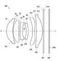
도 1a는, 다양한 실시예들에 따른, 렌즈 어셈블리를 나타내는 구성도이다.
도 1b는, 도 1a와 다른 실시예들에 따른, 렌즈 어셈블리를 나타내는 구성도이다.
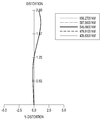
도 2는, 도 1b의 실시예에 따른, 렌즈 어셈블리의 구면수차를 나타내는 그래프이다.
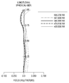
도 3은, 도 1b의 실시예에 따른, 렌즈 어셈블리의 비점수차를 나타내는 그래프이다.
도 4는, 도 1b의 실시예에 따른, 렌즈 어셈블리의 왜곡수차를 나타내는 그래프이다.
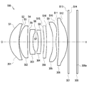
도 5는, 다양한 실시예들 중 다른 실시예에 따른, 렌즈 어셈블리를 나타내는 구성도이다.
도 6은, 도 5의 실시예에 따른, 렌즈 어셈블리의 구면수차를 나타내는 그래프이다.
도 7은, 도 5의 실시예에 따른, 렌즈 어셈블리의 비점수차를 나타내는 그래프이다.
도 8은, 도 5의 실시예에 따른, 렌즈 어셈블리의 왜곡수차를 나타내는 그래프이다.
도 9는, 다양한 실시예들 중 또 다른 실시예에 따른, 렌즈 어셈블리를 나타내는 구성도이다.
도 10은, 도 9의 실시예에 따른, 렌즈 어셈블리의 구면수차를 나타내는 그래프이다.
도 11은, 도 9의 실시예에 따른, 렌즈 어셈블리의 비점수차를 나타내는 그래프이다.
도 12는, 도 9의 실시예에 따른, 렌즈 어셈블리의 왜곡수차를 나타내는 그래프이다.
도 13은, 다양한 실시예들 중 또 다른 실시예에 따른, 렌즈 어셈블리를 나타내는 구성도이다.
도 14는, 도 13의 실시예에 따른, 렌즈 어셈블리의 구면수차를 나타내는 그래프이다.
도 15는, 도 13의 실시예에 따른, 렌즈 어셈블리의 비점수차를 나타내는 그래프이다.
도 16은, 도 13의 실시예에 따른, 렌즈 어셈블리의 왜곡수차를 나타내는 그래프이다.
도 17은, 다양한 실시예들 중 또 다른 실시예에 따른, 렌즈 어셈블리를 나타내는 구성도이다.
도 18은, 도 17의 실시예에 따른, 렌즈 어셈블리의 구면수차를 나타내는 그래프이다.
도 19는, 도 17의 실시예에 따른, 렌즈 어셈블리의 비점수차를 나타내는 그래프이다.
도 20은, 도 17의 실시예에 따른, 렌즈 어셈블리의 왜곡수차를 나타내는 그래프이다.
도 21은, 다양한 실시예들에 따른, 네트워크 환경 내의 전자 장치의 블럭도이다.
도 22는, 다양한 실시예들에 따른, 카메라 모듈을 예시하는 블럭도이다.1A is a configuration diagram illustrating a lens assembly according to various embodiments.
1B is a configuration diagram illustrating a lens assembly according to other embodiments of FIG. 1A.
FIG. 2 is a graph showing spherical aberration of the lens assembly according to the embodiment of FIG. 1B.
3 is a graph showing astigmatism of the lens assembly according to the embodiment of FIG. 1B.
4 is a graph illustrating distortion aberration of the lens assembly according to the embodiment of FIG. 1B.
5 is a configuration diagram illustrating a lens assembly according to another embodiment among various embodiments.
FIG. 6 is a graph showing spherical aberration of the lens assembly according to the embodiment of FIG. 5.
7 is a graph illustrating astigmatism of the lens assembly according to the embodiment of FIG. 5.
8 is a graph showing distortion aberration of the lens assembly according to the embodiment of FIG. 5.
9 is a configuration diagram illustrating a lens assembly according to another embodiment among various embodiments.
10 is a graph illustrating spherical aberration of the lens assembly according to the embodiment of FIG. 9.
FIG. 11 is a graph showing astigmatism of the lens assembly according to the embodiment of FIG. 9.
12 is a graph illustrating distortion aberration of the lens assembly according to the embodiment of FIG. 9.
13 is a configuration diagram illustrating a lens assembly according to another embodiment among various embodiments.
14 is a graph showing spherical aberration of the lens assembly according to the embodiment of FIG. 13.
15 is a graph showing astigmatism of the lens assembly according to the embodiment of FIG. 13.
16 is a graph showing distortion aberration of the lens assembly according to the embodiment of FIG. 13.
17 is a configuration diagram illustrating a lens assembly according to another embodiment among various embodiments.
18 is a graph illustrating spherical aberration of the lens assembly according to the embodiment of FIG. 17.
19 is a graph showing astigmatism of the lens assembly according to the embodiment of FIG. 17.
20 is a graph showing distortion aberration of the lens assembly according to the embodiment of FIG. 17.
21 is a block diagram of an electronic device in a network environment, according to various embodiments.
22 is a block diagram illustrating a camera module, according to various embodiments.
이하, 본 문서의 다양한 실시예들이 첨부된 도면을 참조하여 기재된다. 실시예 및 이에 사용된 용어들은 본 문서에 기재된 기술을 특정한 실시 형태에 대해 한정하려는 것이 아니며, 해당 실시예의 다양한 변경, 균등물, 및/또는 대체물을 포함하는 것으로 이해되어야 한다. 도면의 설명과 관련하여, 유사한 구성요소에 대해서는 유사한 참조 부호가 사용될 수 있다. 단수의 표현은 문맥상 명백하게 다르게 뜻하지 않는 한, 복수의 표현을 포함할 수 있다. 본 문서의 다양한 실시예들에서, "A 또는 B" 또는 "A 및/또는 B 중 적어도 하나" 등의 표현은 함께 나열된 항목들의 모든 가능한 조합을 포함할 수 있다. "제 1," "제 2," "첫째," 또는 "둘째,"등의 표현들은 해당 구성요소들을, 순서 또는 중요도에 상관없이 수식할 수 있고, 한 구성요소를 다른 구성요소와 구분하기 위해 사용될 뿐 해당 구성요소들을 한정하지 않는다. 어떤(예: 제 1) 구성요소가 다른(예: 제 2) 구성요소에 "(기능적으로 또는 통신적으로) 연결되어" 있다거나 "접속되어" 있다고 언급된 때에는, 상기 어떤 구성요소가 상기 다른 구성요소에 직접적으로 연결되거나, 다른 구성요소(예: 제 3 구성요소)를 통하여 연결될 수 있다.Hereinafter, various embodiments of the present document will be described with reference to the accompanying drawings. It should be understood that the examples and terms used therein are not intended to limit the technology described in this document to specific embodiments, but include various modifications, equivalents, and / or substitutes of the examples. In connection with the description of the drawings, similar reference numerals may be used for similar components. Singular expressions may include plural expressions unless the context clearly indicates otherwise. In various embodiments of the present document, expressions such as “A or B” or “at least one of A and / or B” may include all possible combinations of items listed together. Expressions such as "first," "second," "first," or "second," can modify the components, regardless of order or importance, to distinguish one component from another component It is used but does not limit the components. When it is stated that one (eg, first) component is “connected (functionally or communicatively)” to another (eg, second) component or is “connected,” the component is the other It may be directly connected to the component, or may be connected through another component (eg, the third component).
본 문서의 다양한 실시예들에서, "~하도록 구성된(또는 설정된)(configured to)"은 상황에 따라, 예를 들면, 하드웨어적 또는 소프트웨어적으로 "~에 적합한," "~하는 능력을 가지는," "~하도록 변경된," "~하도록 만들어진," "~를 할 수 있는," 또는 "~하도록 설계된"과 상호 호환적으로(interchangeably) 사용될 수 있다. 어떤 상황에서는, "~하도록 구성된 장치"라는 표현은, 그 장치가 다른 장치 또는 부품들과 함께 "~할 수 있는" 것을 의미할 수 있다. 예를 들면, 문구 "A, B, 및 C를 수행하도록 구성된(또는 설정된) 프로세서"는 해당 동작을 수행하기 위한 전용 프로세서(예: 임베디드 프로세서), 또는 메모리 장치에 저장된 하나 이상의 소프트웨어 프로그램들을 실행함으로써, 해당 동작들을 수행할 수 있는 범용 프로세서(예: CPU 또는 application processor)를 의미할 수 있다. In various embodiments of this document, "configured to (or configured)" has the ability to "suitable for," "~", depending on the context, for example, in hardware or software. It may be used interchangeably with "modified to," "made to," "can do," or "designed to". In some situations, the expression "a device configured to" may mean that the device "can" with other devices or parts. For example, the phrase “processors configured (or set) to perform A, B, and C” means by executing a dedicated processor (eg, an embedded processor) to perform the operation, or one or more software programs stored in the memory device. , It may mean a general-purpose processor (for example, a CPU or an application processor) capable of performing the corresponding operations.
본 문서의 다양한 실시예들에 따른 전자 장치는, 예를 들면, 스마트폰, 태블릿 PC, 이동 전화기, 영상 전화기, 전자책 리더기, 데스크탑 PC, 랩탑 PC, 넷북 컴퓨터, 워크스테이션, 서버, PDA, PMP(portable multimedia player), MP3 플레이어, 의료기기, 카메라, 또는 웨어러블 장치 중 적어도 하나를 포함할 수 있다. 웨어러블 장치는 액세서리형(예: 시계, 반지, 팔찌, 발찌, 목걸이, 안경, 콘택트 렌즈, 또는 머리 착용형 장치(head-mounted-device(HMD)), 직물 또는 의류 일체형(예: 전자 의복), 신체 부착형(예: 스킨 패드 또는 문신), 또는 생체 이식형 회로 중 적어도 하나를 포함할 수 있다. 어떤 실시예들에서, 전자 장치는, 예를 들면, 텔레비전, DVD(digital video disk) 플레이어, 오디오, 냉장고, 에어컨, 청소기, 오븐, 전자레인지, 세탁기, 공기 청정기, 셋톱 박스, 홈 오토매이션 컨트롤 패널, 보안 컨트롤 패널, 미디어 박스(예: 삼성 HomeSyncTM, 애플TVTM, 또는 구글 TVTM), 게임 콘솔(예: XboxTM, PlayStationTM), 전자 사전, 전자 키, 캠코더, 또는 전자 액자 중 적어도 하나를 포함할 수 있다.An electronic device according to various embodiments of the present disclosure includes, for example, a smart phone, a tablet PC, a mobile phone, a video phone, an e-book reader, a desktop PC, a laptop PC, a netbook computer, a workstation, a server, a PDA, and a PMP. (portable multimedia player), an MP3 player, a medical device, a camera, or a wearable device. Wearable devices are accessories (e.g. watches, rings, bracelets, anklets, necklaces, glasses, contact lenses, or head-mounted-device (HMD)), fabrics or garments (e.g. electronic clothing), It may include at least one of a body-attached type (eg, a skin pad or tattoo), or a bio-implantable circuit In some embodiments, the electronic device may be, for example, a television, a digital video disk (DVD) player, Audio, refrigerator, air conditioner, cleaner, oven, microwave, washing machine, air purifier, set-top box, home automation control panel, security control panel, media box (e.g. Samsung HomeSync TM , Apple TV TM , or Google TV TM ) , A game console (eg, Xbox TM , PlayStation TM ), an electronic dictionary, an electronic key, a camcorder, or at least one of an electronic picture frame.
다른 실시예에서, 전자 장치는, 각종 의료기기(예: 각종 휴대용 의료측정기기(혈당 측정기, 심박 측정기, 혈압 측정기, 또는 체온 측정기 등), MRA(magnetic resonance angiography), MRI(magnetic resonance imaging), CT(computed tomography), 촬영기, 또는 초음파기 등), 네비게이션 장치, 위성 항법 시스템(GNSS(global navigation satellite system)), EDR(event data recorder), FDR(flight data recorder), 자동차 인포테인먼트 장치, 선박용 전자 장비(예: 선박용 항법 장치, 자이로 콤파스 등), 항공 전자기기(avionics), 보안 기기, 차량용 헤드 유닛(head unit), 산업용 또는 가정용 로봇, 드론(drone), 금융 기관의 ATM, 상점의 POS(point of sales), 또는 사물 인터넷 장치 (예: 전구, 각종 센서, 스프링클러 장치, 화재 경보기, 온도조절기, 가로등, 토스터, 운동기구, 온수탱크, 히터, 보일러 등) 중 적어도 하나를 포함할 수 있다. 어떤 실시예에 따르면, 전자 장치는 가구, 건물/구조물 또는 자동차의 일부, 전자 보드(electronic board), 전자 사인 수신 장치(electronic signature receiving device), 프로젝터, 또는 각종 계측 기기(예: 수도, 전기, 가스, 또는 전파 계측 기기 등) 중 적어도 하나를 포함할 수 있다. 다양한 실시예에서, 전자 장치는 플렉서블하거나, 또는 전술한 다양한 장치들 중 둘 이상의 조합일 수 있다. 본 발명의 다양한 실시예에 따른 전자 장치는 전술한 기기들에 한정되지 않는다. 본 발명의 다양한 실시예에서, 사용자라는 용어는 전자 장치를 사용하는 사람 또는 전자 장치를 사용하는 장치(예: 인공지능 전자 장치)를 지칭할 수 있다. 본 문서의 실시예에 따른 전자 장치는 전술한 기기들에 한정되지 않는다.In another embodiment, the electronic device includes various medical devices (eg, various portable medical measurement devices (such as a blood glucose meter, heart rate monitor, blood pressure meter, or body temperature meter), magnetic resonance angiography (MRA), magnetic resonance imaging (MRI), CT (computed tomography), camera, or ultrasound, etc., navigation device, global navigation satellite system (GNSS), event data recorder (EDR), flight data recorder (FDR), automotive infotainment device, marine electronic equipment (E.g. navigational devices for ships, gyro compasses, etc.), avionics, security devices, head units for vehicles, robots for industrial or domestic use, drones, ATMs in financial institutions, point-of-sale at stores of sales), or at least one of Internet of Things devices (eg light bulbs, various sensors, sprinkler devices, fire alarms, thermostats, street lights, toasters, exercise equipment, hot water tanks, heaters, boilers, etc.). . According to some embodiments, the electronic device may be a furniture, building / structure or part of an automobile, an electronic board, an electronic signature receiving device, a projector, or various measuring devices (eg, water, electricity, Gas, or radio wave measurement devices, etc.). In various embodiments, the electronic device may be flexible or a combination of two or more of the various devices described above. The electronic device according to various embodiments of the present disclosure is not limited to the aforementioned devices. In various embodiments of the present invention, the term user may refer to a person using an electronic device or a device using an electronic device (eg, an artificial intelligence electronic device). The electronic device according to the embodiment of the present document is not limited to the above-described devices.
다양한 실시예들에 따르면, 상기 전자 장치의 대표적인 예로서 광학 장치(optical device)(예: 카메라)가 포함될 수 있으며, 아래의 설명은 일 실시예로서 렌즈 어셈블리가 상기 광학 장치에 탑재되는 것을 전제로 할 수 있다.According to various embodiments, an optical device (eg, a camera) may be included as a representative example of the electronic device, and the following description is based on the assumption that the lens assembly is mounted on the optical device as an embodiment. can do.
본 문서의 다양한 실시예들을 설명함에 있어, 일부 수치 등이 제시될 수 있으나, 이러한 수치는 청구범위에 기재되어 있지 않은 한 본 문서에 개시된 다양한 실시예들을 한정하지는 않는다는 것에 유의해야 한다. In describing various embodiments of the present document, some numbers and the like may be provided, but it should be noted that these numbers do not limit the various embodiments disclosed in the present document unless stated in the claims.
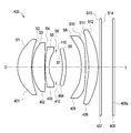
도 1a는, 본 문서에 개시된 다양한 실시예들 중 하나에 따른 렌즈 어셈블리(100)를 나타내는 구성도이다. 도 1b는, 도 1a와 다른 실시예에 따른, 렌즈 어셈블리(100)를 나타내는 구성도이다. 1A is a configuration diagram illustrating a
도 1a를 참조하면, 본 문서에 개시된 다양한 실시예들 중 하나에 따른 렌즈 어셈블리(100)는, 복수의 렌즈들(예: 101, 102, 103, 104, 106)과 이미지 센서(108)를 포함할 수 있다. Referring to FIG. 1A, a
다양한 실시예들에 따르면, 이미지 센서(108)는 전자 장치(electronic device)에 탑재될 수 있다. 복수의 렌즈들을 포함하는 렌즈 어셈블리(100)는, 이미지 센서(108)가 탑재된 상기 광학 장치 및/또는 상기 전자 장치에 장착될 수 있다. 예컨대, 본 문서의 다양한 실시예들을 설명함에 있어, 이미지 센서(108)가 렌즈 어셈블리(100)에 구비된 예를 설명하게 될 것이나, 이미지 센서(108)는 렌즈 어셈블리(100)가 장착되는 상기 광학 장치 및/또는 상기 전자 장치에 장착되어 사용될 수 있다. According to various embodiments, the
다양한 실시예들에 따르면, 이미지 센서(108)는 회로 기판(미도시) 등에 장착되어 광축(O-I)에 정렬된 상태로 배치되는 센서로서, 광에 반응할 수 있다. 이미지 센서(180)는 예를 들어, 씨모스 이미지 센서(CMOS, complementary metal-oxide semiconductor) 또는 전하 결합 소자(CCD, charge coupled device)와 같은 센서를 포함할 수 있다. 이미지 센서(108)는 이에 한정되지 않고, 광, 예를 들면, 피사체 이미지를 전기적인 영상신호로 변환하는 다양한 소자들을 포함할 수 있다. 이미지 센서(108)는 복수의 렌즈들(예: 101, 102, 103, 104, 106)을 통과한 광으로부터 피사체에 대한 명암 정보, 계조비 정보, 색상 정보 등을 검출하여 피사체에 대한 이미지를 획득할 수 있다. According to various embodiments, the
다양한 실시예들에 따르면, 렌즈 어셈블리(100)의 렌즈들은 플라스틱 렌즈를 포함할 수 있으며, 상기 렌즈들의 조합을 통해 상기 렌즈 어셈블리(100)는 대략 70도 이상의 화각을 가질 수 있다. According to various embodiments, lenses of the
다양한 실시예들에 따르면, 렌즈 어셈블리는, 피사체(또는 외부 객체) 측(O, object side)으로부터 상 측(I, image side)으로 광축(O-I)을 가질 수 있다. 이하에서 각 렌즈의 구성을 설명함에 있어, 예를 들면, 피사체 측(object side)은 피사체가 있는 방향을 나타낼 수 있고, 상 측(image side)는 상(image)이 맺히는 결상면(108a)이 있는 방향을 나타낼 수 있다. 또한, 렌즈의 "피사체 측을 향하는 면"은, 예를 들면, 광축(O-I)을 기준으로 하여 피사체가 있는 쪽의 면으로서 도면상 렌즈의 좌측 표면(또는 전면)을 의미하며, "상 측을 향하는 면"은 광축(O-I)을 기준으로 하여 결상면(108a)이 있는 쪽의 면으로 도면상 렌즈의 우측 표면(또는 후면)을 나타낼 수 있다. 여기서 결상면(108a, imaging plane)은 예를 들어, 촬상 소자 또는 이미지 센서(108)가 배치되어 상이 맺히는 부분 수 있다.According to various embodiments, the lens assembly may have an optical axis O-I from an object (or external object) side (O, object side) to an image side (I, image side). In the following description of the configuration of each lens, for example, the object side (object side) may indicate the direction in which the object is present, and the image side (image side) is the image (image) is formed image (108a) is formed Direction can be indicated. In addition, the "face toward the subject side" of the lens means, for example, the surface of the object on the basis of the optical axis OI, and means the left surface (or front side) of the lens in the drawing, and "the image side The "facing surface" refers to the surface on which the
다양한 실시예들에 따르면, 어떤 렌즈(예: 제 1 렌즈)가 피사체 측(O)을 향하는 면을 포함한다고 할 때, 상기 피사체 측(O)을 향하는 면은 제 1 방향을 향한다고 할 수 있다. 그리고 어떤 렌즈(예: 제 1 렌즈)가 상 측(I)을 향하는 면을 포함한다고 할 때, 상기 상 측(I)을 향하는 면은 상기 제 1 방향의 반대 방향을 향하는 제 2 방향을 향한다고 할 수 있다. According to various embodiments, when a lens (eg, a first lens) is said to include a surface facing the object side O, the surface facing the object side O may be said to face the first direction . And when a certain lens (for example, a first lens) includes a surface facing the image side I, the surface facing the image side I faces the second direction facing the opposite direction of the first direction can do.
도 1a를 참조하면, 다양한 실시예들에 따른 렌즈 어셈블리(100)는, 예를 들면, 광축(O-I) 방향(예: 도 1의 피사체(O)에서 상(I) 측으로 향하는 방향)으로 순차적으로 배열된 복수의 렌즈들(101, 102, 103, 104, 106)로서, 제 1 렌즈(101), 제 2 렌즈(102), 제 3 렌즈(103), 제 4 렌즈(104) 및 제 5 렌즈(106) 를 포함할 수 있다. 복수의 렌즈들(예: 101, 102, 103, 104, 106)은 이미지 센서(108)와 광축 정렬된 상태로 배치될 수 있다.Referring to Figure 1a, the
다양한 실시예들에 따른 렌즈 어셈블리(100)는, 제 4 렌즈(104)와 제 5 렌즈(106) 사이에 적어도 하나의 제 6 렌즈(105)를 더 포함할 수 있다. 도 1b를 참조하면, 일 실시예로서 제 4 렌즈(104)와 제 5 렌즈(106) 사이에 1 매로 구성된 제 6 렌즈(105)가 배치된 것이 도시된다. 제 4 렌즈(104)와 제 5 렌즈(106) 사이에 배치되는 렌즈들의 매수는 렌즈 어셈블리(100)가 장착되는 광학 장치의 요구 체적, 요구 광학 성능에 따라 다양하게 지정될 수 있다.The
이하에서는, 제 6 렌즈(105)를 포함하는 복수의 렌즈들(예: 101, 102, 103, 104, 105, 106)을 중심으로 설명할 수 있다. 이하의 실시예들은 제 6 렌즈(105)를 포함하지 않는 복수의 렌즈들(예: 101, 102, 103, 104, 106)을 구비하는 렌즈 어셈블리(예: 도 1a의 렌즈 어셈블리)에 대해서도 준용될 수 있다. Hereinafter, a plurality of lenses (eg, 101, 102, 103, 104, 105, 106) including the
다양한 실시예들에 따른 복수의 렌즈들(예: 101, 102, 103, 104, 105, 106)을 설명함에 있어서, 각 렌즈들에서 광축(O-I)과 가까운 쪽을 이하 '중심부(chief portion)'라 할 수 있으며, 광축(O-I)과 먼 쪽(또는 렌즈의 가장자리 부근)을 이하 '주변부(marginal portion)'라 할 수 있다. 상기 중심부(chief portion)는, 예를 들면, 제 1 렌즈(101)에서 광축(O-I)과 교차하는 부분일 수 있다. 상기 주변부(marginal portion)는, 예를 들면, 제 1 렌즈(101)에서 광축으로부터 소정 거리 이격된 부분일 수 있다. 상기 주변부(marginal portion)는 예를 들면, 렌즈의 광축(O-I)으로부터 가장 멀리 떨어진 렌즈의 단부(end portion)를 포함할 수 있다. In describing a plurality of lenses (eg, 101, 102, 103, 104, 105, 106) according to various embodiments, a side closer to the optical axis OI in each lens is hereinafter referred to as a 'chief portion'. The optical axis OI and the far side (or near the edge of the lens) may hereinafter be referred to as a 'marginal portion'. The chief portion may be, for example, a portion intersecting the optical axis O-I in the
다양한 실시예들에 따르면, 제 1 렌즈(101) 및 제 2 렌즈(102)는 정(positive)의 굴절력을 가질 수 있다. 그리고 제 3 렌즈(103), 제 4 렌즈(104), 는 부(negative)의 굴절력을 가질 수 있다. 그리고, 제 5 렌즈(106)는 정(positive)의 굴절력을 가질 수 있다. According to various embodiments, the
다양한 실시예들에 따르면, 제 4 렌즈(104)와 제 5 렌즈(106) 사이에 배치되는 적어도 하나의 제 6 렌즈(105)는 부(negative)의 굴절력을 가질 수 있다. 도 1b에 도시된 실시예에 따르면, 일 실시예에 따른 1 매의 제 6 렌즈(105)는 부(negative)의 굴절력을 가질 수 있다. 다른 실시예에 따르면, 제 4 렌즈(104)와 제 5 렌즈(106) 사이에 두 매 이상의 제 6 렌즈(105)들이 배치되는 경우에 있어서, 제 4 렌즈(104)와 제 5 렌즈(106) 사이에 배치되는 두 매 이상의 제 6 렌즈(105)들의 조합은 부(negative)의 굴절력을 가질 수 있다. According to various embodiments, the at least one
상술한 실시예들에서, 정의 굴절력을 가지는 렌즈에 광축(O-I)과 평행한 빛이 입사되면, 렌즈를 통과한 빛은 집광될 수 있다. 예를 들면, 정의 굴절력을 가지는 렌즈는 볼록 렌즈의 원리에 기반한 렌즈일 수 있다. 반면에, 부의 굴절력을 가지는 렌즈에 평행한 빛이 입사되면, 렌즈를 통과한 빛은 분산될 수 있다. 예를 들면, 부의 굴절력을 가지는 렌즈는 오목 렌즈의 원리에 기반한 렌즈일 수 있다. 이하에서는, 렌즈 어셈블리에 포함되는 복수의 렌즈들로서, 일 실시예에 따라 제 1 렌즈(101), 제 2 렌즈(102), 제 3 렌즈(103), 제 4 렌즈(104), 제 5 렌즈(106) 및 1 매의 제 6 렌즈(105)로 구성된 복수의 렌즈들을 예시로 들어 설명할 수 있다. 다양한 실시예들에 따르면, 제 1 렌즈(101)의 상기 피사체 측(O)을 향하는 면(S1)은 볼록하게 형성될 수 있고, 제 2 렌즈(102)의 상기 피사체 측(O)을 향한 면(S3) 또한 볼록하게 형성될 수 있다. 일 실시예에 따르면, 제 1 렌즈(101) 또는 제 2 렌즈(102) 중 적어도 하나의 렌즈를, 상 측(I)을 향하는 면이 오목하게 형성되는 메니스커스(meniscus) 렌즈로 구성함으로써, 렌즈의 주변부(marginal portion)를 통해 뚜렷한 상을 맺지 못하게 되는 현상인 코마수차 및 비점수차를 효과적으로 제거할 수 있다. 예를 들면, 제 1 렌즈(101)는 피사체 측(O)을 향하는 면(S1)이 볼록하고 상 측(I)을 향하는 면(S2)이 오목한 메니스커스 렌즈로 구성하고, 제 2 렌즈(102)는 피사체 측(O)을 향하는 면(S3)이 볼록하고 상 측(I)을 향하는 면(S4)이 평면으로 구성된 편평렌즈로 구성할 수 있다. In the above-described embodiments, when light parallel to the optical axis O-I is incident on a lens having positive refractive power, light passing through the lens may be condensed. For example, a lens having positive refractive power may be a lens based on the principle of a convex lens. On the other hand, when light parallel to the lens having negative refractive power is incident, light passing through the lens may be dispersed. For example, a lens having negative refractive power may be a lens based on the principle of a concave lens. Hereinafter, as a plurality of lenses included in the lens assembly, according to an embodiment, the
일 실시예에 따르면, 제 1 렌즈(101) 및 제 2 렌즈(102)는 후술하는 제 3 렌즈(103) 및 제 4 렌즈(104)에 비해 상대적으로 유효경이 큰 대구경 렌즈를 구성할 수 있다. 광학 장치 및/또는 전자 장치 내에서 렌즈는 제한된 공간 내에 설치되어야 하므로, 제 1 렌즈(101) 및 제 2 렌즈(102)는 초점거리가 매우 짧은 것일 수 있다. 제 1 렌즈(101) 및 제 2 렌즈(102)를 통해 강한 정의 굴절력을 제공함으로써 렌즈 어셈블리가 짧은 전장을 갖도록 할 수 있다. 또한, 제 1 렌즈(101) 및 제 2 렌즈(102)를 통해 강한 정의 굴절력을 제공함으로써, 주변부(marginal portion)를 통과한 광선에 의한 결상(imaging)되는 이미지나 영상의 해상도를 증가시킬 수 있으며, 광의 이동 경로를 축소시킬 수 있다. According to an embodiment, the
다양한 실시예들에 따르면, 제 1 렌즈(101) 및 제 2 렌즈(102)의 면들(S1, S2, S3, S4) 중 적어도 하나의 면을 비구면(aspheric)으로 형성할 수 있다. 제 1 렌즈(101) 및 제 2 렌즈(102)는, 후술하겠지만, 이미지 센서(108a)의 길이에 관한 파라미터(Y)에 대하여, 제 1 렌즈(101) 및 제 2 렌즈(102)의 유효 거리에 관한 파라미터(Sag 1, Sag 3)를 지정된 범위를 갖도록 함으로써 컴팩트한 렌즈를 구현하면서도 망원렌즈에 요구되는 화각을 충족시킬 수 있다. 제 1 렌즈(101) 및 제 2 렌즈(102)의 유효 거리 확보시 발생 가능한 구면 수차는, 제 1 렌즈(101) 및 제 2 렌즈(102)의 면들(S1, S2, S3, S4) 중 적어도 하나의 면을 비구면(aspheric)으로 구현함으로써 방지할 수 있다. 일 실시예에 따르면, 이하 후술하는 [표 1], [표 4], [표 7], [표 10], [표 12]에서는 제 1 렌즈(101)의 면(S1, S2)이 모두 비구면인 것을 예시로 할 수 있다. 그리고, [표 10]의 제 2 렌즈(102)의 면(S4)을 제외하고, [표 1], [표 4], [표 7], [표 10], [표 12]의 제 2 렌즈(102)의 면들(S1, S2, S3, S4)은 모두 비구면인 것을 예시로 한다. According to various embodiments, at least one of the surfaces S1, S2, S3, and S4 of the
다양한 실시예들에 따르면, 제 3 렌즈(103)의 상기 상 측(I)을 향하는 면(S6)과, 상기 제 4 렌즈(104)의 피사체 측(O)을 향하는 면(S7)이 오목하게 형성될 수 있다. 즉, 제 1 렌즈(101) 및 제 2 렌즈(102)의 후방에 서로 오목한 면을 마주보고 있는 두 개의 렌즈(제 3 렌즈(103) 및 제 4 렌즈(104))를 배치할 수 있다. 일 실시예에 따르면, 제 3 렌즈(103)를 통해 부의 굴절력을 제공함으로써 대구경으로 구성된 제 1 렌즈(101) 및 제 2 렌즈(102)에 의한 구면 수차를 효과적으로 보상할 수 있다. According to various embodiments, the surface S6 facing the image side I of the
다양한 실시예들에 따르면, 제 3 렌즈(103) 및 제 4 렌즈(104)의 크기는 제 1 렌즈(101) 및 제 2 렌즈(102)의 크기에 비해 상대적으로 작을 수 있다. 제 1 렌즈(101) 및 제 2 렌즈(102)는 상대적으로 대구경으로 구성하여 집광 성능 및 망원비를 높일 수 있고, 제 1 렌즈(101) 및 제 2 렌즈(102)가 강한 정의 굴절력을 갖도록 함에 따라 제 3 렌즈(103) 및 제 4 렌즈(104)는 렌즈의 유효경을 최소화하여 콤팩트한 렌즈 어셈블리를 제공할 수 있다. According to various embodiments, the sizes of the
다양한 실시예들에 따르면, 제 3 렌즈(103)의 상기 피사체 측(O)을 향하는 면(S5)과, 제 4 렌즈(104)의 상 측(I)을 향하는 면(S8)은 각각 편평하거나 볼록하게 형성될 수 있다. 예를 들면, 제 3 렌즈(103)는 피사체 측(O)을 향하는 면(S5)이 볼록하고 상 측(I)을 향하는 면(S6)이 오목하며, 제 4 렌즈(104)는 피사체 측(O)을 향하는 면(S7)이 오목하고 상 측(I)을 향하는 면(S8)이 볼록할 수 있다. According to various embodiments, the surface S5 facing the subject side O of the
일 실시예에 따르면, 제 3 렌즈(103)의 상 측(I) 면의 부의 굴절력을 이용하여 구면수차를 보상할 수 있다.According to an embodiment, spherical aberration may be compensated by using a negative refractive power of an image side (I) surface of the
일 실시예에 따르면, 상기 제 3 렌즈(103) 및 제 4 렌즈(104)의 면들(S5, S6, S7, S8) 중 적어도 하나의 면을 비구면(aspheric)으로 구성하여, 구면수차를 추가로 보상할 수도 있다. According to an embodiment, at least one of the surfaces S5, S6, S7, and S8 of the
다양한 실시예들에 따르면, 제 5 렌즈(106)의 상기 상 측(I)을 향하는 면(S12)은 볼록하게 형성되고, 제 6 렌즈(105)의 상기 피사체 측(O)을 향하는 면(S9)은 오목하게 형성될 수 있다. 제 5 렌즈(106) 및 제 6 렌즈(105)를 이용하여 제 4 렌즈(104)를 통과한 광선에 대해 높이별 적절한 굴절력 배분을 할 수 있다. 제 제 5 렌즈(106) 및 제 6 렌즈(105)는 비구면의 효과가 크기 때문에 광축으로부터의 높이에 따라 다른 굴절력이 부여될 수 있다. 이에 따르면 렌즈의 주변부(marginal portion)를 통과하는 광선이 결상면(108a)에 양호하게 결상될 수 있다. 일 실시예에 따르면, 제 5 렌즈(106)는 정의 굴절력을 갖고, 제 6 렌즈(105)는 부의 굴절력을 가질 수 있다. 이를 통해 색수차(chromatic aberration) 및 상면만곡수차(curvature of field) 보정을 할 수 있다. According to various embodiments, the surface S12 facing the image side I of the
다양한 실시예에 따르면, 제 5 렌즈(106)의 피사체 측(O)을 향하는 면(S11)은 편평하거나 오목할 수 있고, 제 6 렌즈(105)의 상 측(I)을 향하는 면(S10)은 볼록하거나 편평할 수 있다. 일 실시예에 따르면, 제 5 렌즈(106)는 피사체 측(O)을 향하는 면(S11)이 오목하고 상 측(I)을 향하는 면(S12)이 볼록할 수 있다. 그리고 제 6 렌즈(105)는 피사체 측(O)을 향하는 면(S9)이 오목하고 상 측(I)을 향하는 면(S10)도 오목할 수 있다.According to various embodiments, the surface S11 facing the subject side O of the
다양한 실시예들에 따르면, 제 6 렌즈(105)의 피사체 측(O)을 향한 면(S9) 또는 상 측(I)을 향한 면(S10) 중 적어도 하나가 비구면(aspheric)으로 이루어질 수 있다. 이를 통해 광선이 렌즈의 주변부(marginal portion)를 통과할 때 왜곡되는 현상을 방지할 수 있다. 일 실시예에 따르면, 상기 제 5 렌즈(106)의 피사체 측(O)을 향한 면(S11) 또는 상 측(I)을 향한 면(S12) 또한 비구면(aspheric)으로 이루어질 수 있다. 이를 통해 구면수차를 최종적으로 보상할 수도 있다. According to various embodiments, at least one of the surface S9 facing the object side O of the
다양한 실시예들에 따르면, 렌즈 어셈블리(100)를 구성하는 복수의 렌즈들(예: 101, 102, 103, 104, 105, 106)에 있어서, 어느 하나의 렌즈와 인접하는 다른 렌즈 간의 간격이 좁을수록, 렌즈 어셈블리(100)의 전장(광축 방향으로 상기 렌즈 어셈블리의 전체 길이)이 짧아질 수 있다. 예를 들어, 본 문서에 개시된 다양한 실시예들에 따른 렌즈 어셈블리(100)가 포함된 광학 장치 및/또는 전자 장치를 작은 크기로 만들고자 하는 경우 렌즈 어셈블리(100)의 전장의 길이를 가능한 짧게 유지시키는 것이 유리하다. 다만, 적절한 망원비가 확보된 상태에서 렌즈 어셈블리(100)의 전장의 길이를 짧게 하는 것은 물리적으로 한계를 가질 수 있다. 본 문서에 개시된 다양한 실시예에 따르면, 상기 복수의 렌즈들(예: 101, 102, 103, 104, 105, 106)의 간격은 상기 렌즈 어셈블리(100)에 요구되는 광학 특성(예: 수차 특성, 광각 특성 및/또는 밝기 특성)에 따라 다양하게 설계될 수 있다. According to various embodiments, in a plurality of lenses (eg, 101, 102, 103, 104, 105, 106) constituting the
다양한 실시예들에 따르면, 본 문서에 개시된 렌즈의 곡률 반지름, 두께, TTL, 초점거리 등은 특별한 언급이 없는 한 모두 ㎜ 단위를 가질 수 있다. 또한, 렌즈의 두께, 렌즈들 간의 간격, TTL(또는 OAL)은 렌즈의 광축을 중심으로 측정된 거리일 수 있다. 아울러, 렌즈의 형상에 대한 설명에서 일면이 볼록한 형상이라는 의미는 해당 면의 광축 부분이 볼록하다는 의미이고, 일면이 오목한 형상이라는 의미는 해당 면의 광축 부분이 오목하다는 의미일 수 있다. 따라서, 렌즈의 일면(해당 면의 광축 부분)이 볼록한 형상이라고 설명되어도, 렌즈의 가장자리 부분(해당 면의 광축 부분으로부터 소정거리 이격된 부분)은 오목할 수 있다. 마찬가지로, 렌즈의 일면(해당 면의 광축 부분이)이 오목한 형상이라고 설명되어도, 렌즈의 가장자리 부분(해당 면의 광축 부분으로부터 소정거리 이격된 부분)은 볼록할 수 있다. 그리고 이하의 상세한 설명 및 청구범위에서 변곡점(inflection point)이라 함은 광축과 교차하지 않는 부분에서 곡률 반지름이 변경되는 지점을 의미한다. According to various embodiments, the curvature radius, thickness, TTL, focal length, and the like of the lenses disclosed in this document may all have a unit of mm unless otherwise specified. In addition, the thickness of the lens, the distance between the lenses, TTL (or OAL) may be a distance measured around the optical axis of the lens. In addition, in the description of the shape of the lens, the meaning that one surface is convex means that the optical axis portion of the surface is convex, and that the one surface is concave shape may mean that the optical axis portion of the surface is concave. Therefore, even if it is described that one surface of the lens (the optical axis portion of the surface) is convex, the edge portion of the lens (the portion spaced a predetermined distance from the optical axis portion of the surface) may be concave. Similarly, even if it is described that one surface of the lens (the optical axis portion of the surface) is concave, the edge portion of the lens (the portion spaced a predetermined distance from the optical axis portion of the surface) can be convex. And in the following detailed description and claims, the inflection point means a point at which the radius of curvature changes in a portion that does not intersect the optical axis.
다양한 실시예에 따르면, 렌즈 어셈블리(100)는, 적어도 하나의 조리개를 포함할 수 있다. 조리개의 크기가 조절됨으로써, 이미지 센서(108)의 결상면(108a)에 도달하는 빛의 양이 조절될 수 있다. 조리개의 위치는 다양할 수 있다. 예를 들면, 후술하는 도 13에 도시된 바와 같이, 제 3 렌즈의 상 측(I)을 향하는 면(S6)과 제 4 렌즈의 피사체 측(O)을 향하는 면(S7) 사이에 조리개(예: 후술하는 도 13의 410)가 배치될 수 있다. 일 실시예에 따르면 조리개는 복수개가 구비될 수도 있다.According to various embodiments, the
다양한 실시예에 따르면, 렌즈 어셈블리(100)는, 상기 제 5 렌즈(106)와 이미지 센서(108) 사이에 배치된 필터(107)를 더 포함할 수 있다. 필터(107)는, 광학 장치의 필름이나 이미지 센서에서 검출되는 빛, 예컨대, 적외선을 차단할 수 있다. 필터(107)는, 예를 들어, 저역 통과 필터(low pass filter), 또는 커버 글라스 중 적어도 하나를 포함할 수 있다. 예컨대, 필터(107)를 장착하는 경우, 이미지 센서(108)를 통해 검출, 촬영되는 이미지 등의 색감을 사람이 실제 사물을 보았을 때 느끼는 색감에 근접하게 할 수 있다. 또한, 필터(107)는 가시광선을 투과하고, 적외선을 외부로 방출하도록 하여, 적외선이 이미지 센서의 결상면(108a)에 전달되는 것을 방지할 수 있다. According to various embodiments, the
다양한 실시예에 따르면, 상기 제 5 렌즈(106) 또는 상기 제 6 렌즈(105) 중 적어도 하나의 렌즈는, 변곡점(inflection point)을 가지는 면을 적어도 하나 포함할 수 있다. 상기 변곡점은, 예를 들면, 곡률 반경의 부호가 (+)에서 (-)로 변하거나 (-)에서 (+)로 변하는 점을 나타낼 수 있다. 또는, 상기 변곡점은, 예를 들면, 렌즈의 형상이 볼록(convex)에서 오목(concave)으로 변하거나 오목에서 볼록으로 변하는 점을 나타낼 수 있다. 상기 곡률 반경(radius of curvature)은, 예를 들면, 곡면이나 곡선의 각 점에 있어서의 만곡의 정도를 표시하는 값을 나타낼 수 있다.According to various embodiments, at least one of the
다양한 실시예들에 따르면, 상기 제 1 렌즈(101)의 피사체 측을 향한 면(S1)을 볼록하게 형성함에 따라, 대구경에 따른 구면수차의 증가를 억제할 수 있다. 렌즈 어셈블리 또는 전자 장치의 전장을 짧게하는 효과를 가질 수도 있다. According to various embodiments, as the surface S1 facing the subject side of the
다양한 실시예들에 따르면, 상기 제 2 렌즈(102)는 강한 정의 굴절력을 형성할 수 있다. 그리고, 상기 제 2 렌즈(102)의 피사체 측을 향한 면(S3)의 중심부 또한 볼록하게 형성함에 따라, 대구경에 따른 구면수차를 효과적으로 보정할 수 있다. 다양한 실시예들에 따르면, 상기 제 2 렌즈(102)의 피사체 측을 향한 면(S3)과 상측을 향한 면(S4)이 굴절력을 적절히 분배하여 제조 오차에 의한 성능 저하를 줄일 수 있다.According to various embodiments, the
다양한 실시예들에 따르면, 상기 제 3 렌즈(103)는 부의 굴절력을 가지면서 상기 제 3 렌즈(103)의 피사체 측을 향한 면(S5)이 오목하게 형성됨에 따라, 상기 제 2 렌즈(102)에 의해 발생될 수 있는 코마수차와 상면만곡을 효과적으로 보정할 수 있다. 또한, 상기 제 3 렌즈(103)는 분산값이 높은 소재를 사용하여 상기 제 1 렌즈(101)와 상기 제 2 렌즈(102)에서 발생될 수 있는 색수차를 효과적으로 보정할 수 있다.According to various embodiments, as the
다양한 실시예들에 따르면, 상기 제 4 렌즈(104)는 비구면으로 이루어짐에 따라, 상기 이미지 센서(108)의 주변부(예를 들면, 상기 이미지 센서(108)의 광축에서부터 이격된 부분)에서 코마가 발생되는 것을 방지할 수 있다. 그리고, 상기 제4 렌즈(104)는 정의 굴절력 또는 부의 굴절력을 가질 수 있다. 또 다른 실시예에 따르면, 상기 제1, 제2, 제3 렌즈(101, 102, 103)에 의해 상기 렌즈 어셈블리(100)의 굴절력 배분이 결정됨에 따라, 상기 제 4 렌즈(104)는 굴절력을 가지지 않을 수 있다.According to various embodiments, as the
상기 제 5 렌즈(106)의 피사체 측을 향한 면(S11) 또는 상기 제 5 렌즈(106)의 상 측을 향한 면(S12)는 적어도 하나의 변곡점을 포함함에 따라, 상기 이미지 센서의 결상면(108a)의 중심으로부터 주변부까지의 상면만곡이 발생되는 것을 줄일 수 있다.The imaging surface of the image sensor (because the surface S11 facing the subject side of the
상기 제 6 렌즈(105)의 피사체 측을 향한 면(S9)은 오목하게 형성됨에 따라, 상기 이미지 센서의 결상면(108a)으로 입사하는 광이 광축에 대해 작은 기울기를 갖도록 하여 이미지 센서(180)의 주변부의 광량을 확보할 수 있다. 이를 통하여, 대구경으로 이루어진 복수의 렌즈들(예: 101, 102, 103, 104, 105, 106)로 구성된 렌즈 어셈블리(100)는 낮은 조도에서도 이미지 센서의 결상면(108a)에서 양호한 밝기의 피사체 이미지가 획득되도록 할 수 있다. 상기와 같은 렌즈 어셈블리(100)는, 대략 80도 정도의 화각을 가지면서, As the surface S9 toward the subject side of the
다음의 [수학식 1]을 만족함으로써, 소형화되면서도 양호한 광학 특성을 가질 수 있다.By satisfying the following [Equation 1], it is possible to have a small size and good optical properties.
![]()
![]()
여기서, TTL은 상기 렌즈 어셈블리(100)의 전장(total track)(예: 제 1 렌즈의 피사체 측(O) 면(S1)으로부터 결상면(108a)까지의 거리), θ는 상기 렌즈 어셈블리(100)의 반화각(half-ANG)을 의미할 수 있다. 상기 [수학식 1]을 만족함으로써, 망원렌즈의 화각을 확보면서도 렌즈 어셈블리를 소형화 시킬 수 있다. 예컨대, 렌즈 어셈블리(100)의 반(half) 화각에 대한 탄젠셜(tangential) 파라미터와 렌즈 어셈블리(100)의 전장의 비율을 상한값인 25를 초과하면 렌즈 어셈블리의 컴팩트한 구성이 불가능하게 되고, 반대로 하한값인 8을 하회하면 망원렌즈의 화각을 달성하기 어렵거나, 렌즈 어셈블리의 과도한 전장 길이의 축소로 렌즈 가공성이 어려워질 수 있다. Here, TTL is the total track of the lens assembly 100 (for example, the distance from the subject side O surface S1 of the first lens to the
또한, 상기 렌즈 어셈블리(100)는 다음의 [수학식 2]을 만족할 수 있다.In addition, the
![]()
![]()
여기서, Sag_13은 상기 제 1 렌즈(101)의 구결 표면(sagittal plane) 상의 유효거리(Sag_1)와 제 2 렌즈(102)의 구결 표면(sagittal plane) 상의 유효거리(Sag_2)의 합, Y는 상기 제 1 렌즈(101), 상기 제 2 렌즈(102), 상기 제 3 렌즈(103), 상기 제 4 렌즈(104), 상기 제 6 렌즈(105) 및 상기 제 5 렌즈(106)들을 순차적으로 통과한 피사체 이미지를 검출하는 이미지 센서(108)의 대각선 길이의 절반을 의미할 수 있다. 이미지 센서(108)의 길이에 대한 파라미터(Y)에 대하여, 제 1 렌즈(101)의 구결 표면(sagittal plane)과 제 2 렌즈(102)의 구결 표면(sagittal plane)의 유효거리(Sag_1, Sag_2)의 합(Sag_13)을 조절함에 따라, 대구경 렌즈들에 따른 이미지 센서 주변부의 코마수차를 적절히 보정할 수 있다. 일 실시예에 따르면, 이미지 센서의 대각선 길이에 대하여 제 1 렌즈(101) 및 제 2 렌즈(102)의 구결 표면 상의 유효거리(Sag_13)의 비율이 하한값인 0.3을 초과하도록 함으로써 대구경 렌즈들이 일정 비율의 정의 굴절력을 유지하도록 하면서, 이미지 센서(108)의 대각선 길이에 대하여 제 1 렌즈(101) 및 제 2 렌즈(102)의 구결 표면 상의 유효거리(Sag_13)의 비율이 상한값인 0.8 미만이 되도록 함에 따라, 부의 굴절력이 증가하는 것을 방지하여 코마수차를 적절히 보정할 수 있다. 그리고 상기 상한값을 벗어나는 범위에서는 코마수차를 효과적으로 보정하는 것이 어려워지거나 렌즈의 가공성이 나빠질 수 있다. 상기 하한값을 하회하는 경우에도 굴절력이 과도히 작아 광학 전장이 길어지는 문제가 발생할 수 있다. Here, Sag_13 is the sum of the effective distance (Sag_1) on the concave surface (sagittal plane) of the
또한, 상기 렌즈 어셈블리는 다음의 [수학식 3]을 만족할 수 있다.In addition, the lens assembly may satisfy the following [Equation 3].
![]()
![]()
여기서, ET1은 상기 제 1 렌즈의 주변부(marginal portion) 중 일측 단부의 두께일 수 있고, ET2는 상기 제 2 렌즈의 주변부(marginal portion) 중 일측 단부의 두께일 수 있다. 그리고 CT1은 상기 제 1 렌즈의 중심부(chief portion)의 두께일 수 있으며, CT2는 상기 제 2 렌즈의 중심부(chief portion)의 두께일 수 있다. 상기 제 1 렌즈 및 제 2 렌즈의 주변부의 두께의 합이 상기 제 1 렌즈 및 제 2 렌즈의 중심부의 두께의 합보다 작되, 상기 제 1 렌즈 및 제 2 렌즈의 주변부의 두께의 합이 상기 제 1 렌즈 및 제 2 렌즈의 중심부의 두께의 합에 대하여 0.2 를 초과함으로써, 유효한 정의 굴절력을 확보하는 한편, 0.45 미만의 두께를 갖도록 할 수 있다. 제 1 렌즈 및 제 2 렌즈의 중심부의 두께의 합에 대하여 0.2 미만이 되면 가공성이 극도로 저하될 수 있다. 제 1 렌즈 및 제 2 렌즈의 중심부의 두께의 합에 대하여 0.45 를 초과하게 되면 정의 굴절력이 부족하여 광학 전장이 길어질 수 있다. Here, ET1 may be the thickness of one end of the marginal portion of the first lens, and ET2 may be the thickness of one end of the marginal portion of the second lens. Further, CT1 may be the thickness of the chief portion of the first lens, and CT2 may be the thickness of the chief portion of the second lens. The sum of the thickness of the peripheral portion of the first lens and the second lens is smaller than the sum of the thickness of the center portion of the first lens and the second lens, and the sum of the thickness of the peripheral portion of the first lens and the second lens is the first By exceeding 0.2 with respect to the sum of the thicknesses of the center portion of the lens and the second lens, an effective positive refractive power can be secured while having a thickness of less than 0.45. When the sum of the thicknesses of the centers of the first lens and the second lens is less than 0.2, workability may be extremely deteriorated. When the sum of the thicknesses of the centers of the first lens and the second lens exceeds 0.45, the positive refractive power is insufficient and the optical length may be long.
상기 [수학식 1] 내지 [수학식 3]을 통해 피사체 측(O)에 배치된 정의 굴절력을 갖는 렌즈들(예: 제 1 렌즈 및 제 2 렌즈)의 형상을 정의할 수 있다.Through [Equations 1] to [Equation 3], the shapes of lenses (eg, the first lens and the second lens) having positive refractive power disposed on the object side O may be defined.
또한, 상기 렌즈 어셈블리(100)는 다음의 [수학식 4]를 만족할 수 있다.In addition, the
![]()
![]()
여기서, DS1은 상기 제 1 렌즈(101)의 유효경, TTL은 상기 렌즈 어셈블리(100)의 전장 길이를 의미할 수 있다. 렌즈 어셈블리(100)의 전장 길이 대비, 제 1 렌즈(101)의 유효경이 0.23을 초과하게 함으로써 대구경을 구현함과 동시에 0.8 미만이 되도록 함으로써 광학 전장의 길이가 과도하게 증가하는 것을 방지할 수 있다. Here, D S1 is the effective diameter of the
또한, 상기 렌즈 어셈블리(100)는 다음의 [수학식 5]를 만족할 수 있다.In addition, the
![]()
![]()
여기서, fair는 상기 제 3 렌즈(103) 및 상기 제 4 렌즈(104)의 합성 초점거리를 나타내며, efl은 상기 렌즈 어셈블리(100)의 합성 초점거리를 나타낼 수 있다. 상기 조건식의 상한값인 -0.2를 초과하게 도면 원하는 부의 굴절력을 획득할 수 없으며, 충분한 구면수차의 보정을 어렵게 할 수 있다. 반대로 하한값인 -1.5를 하회하게 되면 수차 보정에는 용이하지만 후초점의 거리가 길어져, 결상면(108a)에 맺히는 상의 주변부의 coma flare가 커져 주변부에 충분한 광학성능을 확보하는 것이 불가능할 수 있다. Here, fair represents the combined focal length of the
또한, 상기 렌즈 어셈블리(100)는 다음의 [수학식 6] 내지 [수학식 9]를 만족할 수 있다.In addition, the
![]()
![]()
![]()
![]()
![]()
![]()
![]()
![]()
여기서, Vd_p는 상기 제 1 렌즈(101) 및 상기 제 2 렌즈(102)의 아베수(Abbe's number)의 평균을 의미할 수 있다. 여기서, Vd_n는 상기 제 3 렌즈(103) 및 상기 제 4 렌즈(104)의 아베수(Abbe's number)의 평균을 의미할 수 있다. 여기서, Vd_pL은 상기 제 5 렌즈(106)의 아베수(Abbe's number)를 의미할 수 있다. 여기서, Vd_nL는 상기 제 6 렌즈(105)의 아베수(Abbe's number)를 의미할 수 있다. 일 실시예에 따르면, 상기 제 1 렌즈(101) 및 상기 제 2 렌즈(102)의 아베수 평균과, 제 3 렌즈(103) 및 제 4 렌즈(104)의 아베수 평균이 적어도 대략 15 이상의 차이가 나도록 설정할 수 있다. 그리고, 제 5 렌즈(105)의 아베수와 제 6 렌즈(105)의 아베수는 적어도 대략 10 이상의 차이가 나도록 설정할 수 잇다. 상술한 바와 같이, 제 1 렌즈(101) 및 제 2 렌즈(102), 제 3 렌즈(103), 제 4 렌즈(104), 제 5 렌즈(106) 및 제 6 렌즈(105)의 아베수를 조절하여 렌즈 어셈블리의 색수차, 특히 종색수차가 증가하는 것을 방지하여 이미지 센서의 결상면(108a)에 적절한 수준의 화질을 확보할 수 있다. 하기의 [표 1]은 상기 렌즈 어셈블리(100)의 각종 렌즈 데이터를 기재한 것으로서, 'S1~S14'는 관련된 복수의 렌즈들(예: 101, 102, 103, 104, 105, 106) 및/또는 필터(107)의 표면을 지칭할 수 있다. 그리고, Radius은 렌즈의 곡률 반경을, Thick은 렌즈의 두께 또는 공기 간격을, H-Ape는 렌즈의 반경을, EFL은 렌즈의 초점거리를, nd는 매질(예: 렌즈)의 굴절률을, vd는 렌즈의 아베수를 의미할 수 있다. 하기 [표 1]에 포함된 렌즈 어셈블리(100)는 F-수(F-No)가 대략 1.773이고, 화각(ANG)이 대략 46도이며, 대략 5.85mm의 합성 초점거리를 가지면서 상술한 조건(및/또는 상술한 조건들 중 적어도 하나)들을 만족할 수 있다.Here, Vd_p may mean an average of Abbe's number of the
하기의 [표 2] 및 [표 3]은 상기 복수의 렌즈들(예: 101, 102, 103, 104, 105, 106)의 비구면 계수를 기재한 것으로서, 비구면 계수는 다음의 [수학식 10]을 통해 산출될 수 있다. [Table 2] and [Table 3] below describe the aspheric coefficients of the plurality of lenses (eg, 101, 102, 103, 104, 105, 106), and the aspheric coefficients are as follows. Can be calculated through
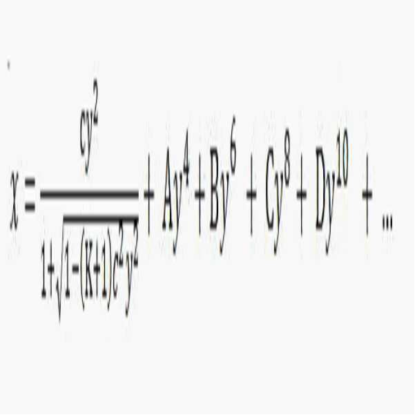
여기서, 'x'는 렌즈의 정점으로부터 광축(O-I) 방향의 거리를, 'c'는 렌즈의 기본 곡률을, 'y'는 광축에 수직인 방향으로의 거리를, 'K'는 코닉(Conic) 상수를, 'A', 'B', 'C', 'D', 'E', 'F'는 비구면 계수를 각각 의미할 수 있다.Here, 'x' is the distance in the direction of the optical axis (OI) from the vertex of the lens, 'c' is the basic curvature of the lens, 'y' is the distance in the direction perpendicular to the optical axis, and 'K' is the conic ) A constant, 'A', 'B', 'C', 'D', 'E', and 'F' may mean aspheric coefficients, respectively.
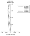
도 2는 본 문서에 개시된 다양한 실시예들 중 하나(예: 도 1b의 실시예)에 따른, 렌즈 어셈블리(100)의 구면수차(spherical aberration)를 나타내는 그래프이다. 구면 수차는 렌즈의 서로 다른 부분(예: 중심부(chief portion), 주변부(marginal portion))을 통과하는 광들의 초점을 맺는 위치가 달라지는 현상일 수 있다.2 is a graph showing spherical aberration of the
도 2에서, 가로축은 종방향 구면수차(longitudinal spherical aberration)의 정도를 나타내고, 세로축은 광축의 중심으로부터의 거리를 규격화(normalization)하여 나타낸 것으로서, 빛의 파장에 따른 종방향 구면수차의 변화가 도시될 수 있다. 종방향 구면수차는, 예를 들면, 파장이 각각 대략 656.2700nm(nanometer), 대략 587.5600nm, 대략 546.0900nm, 대략 479.9100nm, 또는 대략 435.8300nm인 광에 대해 각각 나타낼 수 있다. 도 2를 살펴보면, 가시광 대역에서의 본 문서에 개시된 다양한 실시예들에 따른 렌즈 어셈블리의 종방향 구면수차는 +0.050에서 -0.050 이내로 제한되어 안정적인 광학 특성을 보임을 확인할 수 잇다.In Fig. 2, the horizontal axis represents the degree of longitudinal spherical aberration, and the vertical axis represents the normalization of the distance from the center of the optical axis, showing the change in the longitudinal spherical aberration according to the wavelength of light. Can be. Longitudinal spherical aberration may be represented, for example, for light having a wavelength of approximately 656.2700 nm (nanometer), approximately 587.5600 nm, approximately 546.0900 nm, approximately 479.9100 nm, or approximately 435.8300 nm, respectively. Referring to FIG. 2, it can be seen that the longitudinal spherical aberration of the lens assembly according to various embodiments disclosed in the present document in the visible light band is limited to within +0.050 to −0.050 and exhibits stable optical properties.
도 3은 본 문서에 개시된 다양한 실시예들 중 하나(예: 도 1b의 실시예)에 따른, 렌즈 어셈블리(100)의 비점수차(astigmatism)를 나타내는 그래프이다. 비점수차는 렌즈의 자오상면(tangential plane 또는 meridian plane)과 구결상면(sagittal plane)이 서로 다른 반경을 가질 때, 수직선 방향과 수평선 방향을 통과하는 광의 초점이 서로 어긋나는 것일 수 있다. 3 is a graph showing astigmatism of the
도 3에서, 상기 렌즈 어셈블리(100)의 비점수차는 대략 546.0900nm의 파장에서 얻어진 결과로서, 실선은 탄젠셜(tangential) 방향의 비점수차(예: 자오상면 만곡)를 나타내고, 점선은 시상(saggital) 방향의 비점수차(예: 구결상면 만곡)를 의미할 수 있다. 도 3을 통해 확인할 수 있는 바와 같이, 본 문서의 다양한 실시예들에 따른, 비점수차는 +0.050에서 -0.050 이내로 제한되어 안정적인 광학 특성을 보임을 확인할 수 잇다. In FIG. 3, the astigmatism of the
도 4는 본 문서에 개시된 다양한 실시예들 중 하나(예: 도 1b의 실시예)에 따른, 렌즈 어셈블리(100)의 왜곡수차(distortion)를 나타내는 그래프이다. 왜곡수차는 광축(O-I)으로부터 거리에 따라 광학배율이 달라지게 되기 때문에 발생하는 것으로서, 이론적인 결상면에 맺히는 상에 비해, 실제 결상면(예: 도 1의 108a)에 맺히는 상이 크거나 작게 보이는 것일 수 있다.4 is a graph showing distortion of the
도 4에서, 상기 렌즈 어셈블리(100)의 왜곡은 대략 546.0900nm의 파장에서 얻어진 결과로서, 렌즈 어셈블리(100)를 통해 촬영된 이미지(image)는, 상기 광축(O-I)에서 벗어난 지점에서 다소 왜곡이 발생할 수 있다. 다만, 이러한 왜곡은 렌즈를 이용하는 광학 장치에서 일반적으로 나타날 수 있는 정도의 것이며, 왜곡율이 대략 3% 미만으로서, 양호한 광학 특성을 제공할 수 있다. In FIG. 4, the distortion of the
도 5는, 본 문서에 개시된 다양한 실시예들 중 다른 하나에 따른, 렌즈 어셈블리(200)를 나타내는 구성도이다. 도 6은, 도 5의 실시예에 따른, 렌즈 어셈블리(200)의 구면수차를 나타내는 그래프이다. 도 7은, 도 5의 실시예에 따른, 렌즈 어셈블리(200)의 비점수차를 나타내는 그래프이다. 도 8은, 도 5의 실시예에 따른, 렌즈 어셈블리(200)의 왜곡수차를 나타내는 그래프이다. 5 is a configuration diagram illustrating the
상술한 실시예들에 따른, 렌즈 어셈블리(100)에 대한 설명은 이하 후술하는 다른 다양한 실시예들에 따른 렌즈 어셈블리들(200, 300, 400, 500)에 준용될 수 있다. 복수의 렌즈 어셈블리(100, 200, 300, 400, 500)들 중 일부는 동일한 렌즈 속성(예: 화각, 초점 거리, 자동 초점, f 넘버(f number), 또는 광학 줌)을 갖거나, 또는 적어도 하나의 렌즈 어셈블리는 다른 렌즈 어셈블리의 렌즈 속성들과 다른 하나 이상의 렌즈 속성들을 가질 수 있다. The description of the
복수의 렌즈 어셈블리(100, 200, 300, 400, 500)들은 플래쉬(후술하는 도 22의 2220), 이미지 센서(108, 208, 308, 408, 508), 이미지 스태빌라이저(후술하는 도 22의 2240), 메모리(후술하는 도 22의 2250), 또는 이미지 시그널 프로세서(후술하는 도 22의 2260)을 포함하여 광학장치(예: 카메라 모듈)을 구성할 수 있다. A plurality of lens assemblies (100, 200, 300, 400, 500) are flash (2220 of FIG. 22 to be described later), image sensors (108, 208, 308, 408, 508), image stabilizer (2240 of FIG. 22 to be described later) An optical device (eg, a camera module) may be configured by including a memory (2250 in FIG. 22 to be described later) or an image signal processor (2260 in FIG. 22 to be described later).
이하의 본 문서의 다양한 실시예들을 설명함에 있어, 전술한 실시예들을 통해 용이하게 이해할 수 있는 구성요소들에 대해서는 도면의 참조번호를 유사하게 부여하거나 생략할 수 있다. 또한, 그에 대한 상세한 설명도 중복될 수 있는 범위에서는 생략될 수 있다. In describing various embodiments of the present document, reference numerals in the drawings may be similarly assigned or omitted for elements that can be easily understood through the above-described embodiments. In addition, a detailed description thereof may be omitted in a range that may be overlapped.
도 5 내지 도 8을 함께 참조하면, 본 문서에 개시된 다양한 실시예들 중 상기 도 1의 실시예와 다른 하나에 따른 렌즈 어셈블리(200)는, 복수의 렌즈들(예: 201, 202, 203, 204, 205, 206), 이미지 센서(208) 및/또는 필터(207)를 포함할 수 있다. Referring to FIGS. 5 to 8 together, the
하기의 [표 4]는 도 5의 실시예에 따른, 렌즈 어셈블리(200)의 각종 렌즈 데이터를 나타낼 수 있다. 하기의 [표 5] 및 [표 6]은 상기 복수의 렌즈들(201, 202, 203, 204, 205, 206)의 비구면 계수를 각각 기재한 것일 수 있다. 여기서, 렌즈 어셈블리(200)는 F-수(F-no)가 대략 1.9772이고, 화각(ANG)이 대략 49.4도이며, 대략 5.996mm의 초점거리를 가지면서 상술한 조건들(및/또는 상술한 조건들 중 적어도 하나)을 만족할 수 있다.The following [Table 4] may represent various lens data of the
도 9는, 본 문서에 개시된 다양한 실시예 중 또 다른 하나에 따른 렌즈 어셈블리(300)를 나타내는 구성도이다. 도 10은, 도 9의 실시예에 따른, 렌즈 어셈블리(300)의 구면수차를 나타내는 그래프이다. 도 11은, 도 9의 실시예에 따른, 렌즈 어셈블리(300)의 비점수차를 나타내는 그래프이다. 도 12는, 도 9의 실시예에 따른, 렌즈 어셈블리(300)의 왜곡수차를 나타내는 그래프이다. 9 is a configuration diagram illustrating a
도 9 내지 도 12를 참조하면, 본 문서에 개시된 다양한 실시예들 중 또 다른 하나에 따른 렌즈 어셈블리(300)는, 복수의 렌즈들(301, 302, 303, 304, 309, 305, 306), 이미지 센서(308), 및/또는 필터(307)를 포함할 수 있다. 도 9 내지 도 12에 도시된 실시예에서는 전술한 실시예들과 달리 하나의 렌즈(309)를 추가로 구비한 것일 수 있다. 여기서 추가되는 렌즈(309)는 렌즈(305)와 함께 제 6 렌즈에 포함되는 렌즈일 수 있다. 9 to 12, a
하기의 [표 7]은 렌즈 어셈블리(300)의 각종 렌즈 데이터를 나타낼 수 있으며, 하기의 [표 8] 및 [표 9]는 상기 복수의 렌즈들(301, 302, 303, 304, 309, 305, 306)의 비구면 계수를 각각 기재한 것일 수 있다. 여기서, 상기 렌즈 어셈블리(300)는 F-수(F-no)가 대략 1.9883이고, 화각(ANG)이 대략 50.1도이며, 대략 5.9963mm의 초점거리를 가지면서 상술한 조건들(및/또는 상술한 조건들 중 적어도 하나)을 만족할 수 있다.The following [Table 7] may represent various lens data of the
도 13은, 본 문서에 개시된 다양한 실시예들 중 또 다른 하나에 따른 렌즈 어셈블리(400)를 나타내는 구성도이다. 도 14는, 도 13의 실시예에 따른, 렌즈 어셈블리(400)의 구면수차를 나타내는 그래프이다. 도 15는, 도 13의 실시예에 따른, 렌즈 어셈블리(400)의 비점수차를 나타내는 그래프이다. 도 16은, 도 13의 실시예에 따른, 렌즈 어셈블리(400)의 왜곡수차를 나타내는 그래프이다. 13 is a configuration diagram illustrating a
도 13 내지 도 16을 참조하면, 본 문서에 개시된 다양한 실시예들 중 또 다른 하나에 따른 렌즈 어셈블리(400)는, 복수의 렌즈들(예: 401, 402, 403, 404, 405, 406), 이미지 센서(408), 및/또는 필터(407)을 포함할 수 있다. 13 to 16, a
다양한 실시예들에 따르면, 렌즈 어셈블리(400)에는 적어도 하나의 조리개(410)가 포함될 수 있다. 예를 들면, 조리개(410)는 상기 제 3 렌즈(403) 및 상기 제 4 렌즈(404) 사이에 배치되어 광량을 조절할 수 있다. 이외에도 렌즈 어셈블리(400)의 또 다른 위치에 다른 조리개(미도시) 추가로 또는 대체적으로 구비될 수도 있다. According to various embodiments, the
하기의 [표 10]은 렌즈 어셈블리(400)의 각종 렌즈 데이터를 나타낼 수 있다. 그리고 하기 [표 11]은 복수의 렌즈들(401, 402, 403, 404, 405, 406)의 비구면 계수를 각각 기재한 것일 수 있다. 여기서, 렌즈 어셈블리(400)는 F-수(F-no)가 1.816이고, 화각(ANG)이 49.7도이며, 5.98mm의 초점거리를 가지면서 상술한 조건들(및/또는 상술한 조건들 중 적어도 하나)을 만족할 수 있다. Table 10 below may represent various lens data of the
전술한 실시예와 달리, 제 2 렌즈(102)의 상(I) 측을 향하는 면(S4)과 제 3 렌즈(103)의 피사체(O) 측을 향하는 면(S5)과, 제 5 렌즈(106)의 상(I) 측을 향하는 면(S12)은 구면(spheric)일 수 있다. 이에 따라 하기 [표 11]에서는 전술한 실시예와 달리 면(S4, S5, S12)의 비구면(aspheric) 계수가 생략될 수 있다. Unlike the above-described embodiment, the surface S4 facing the image I side of the
도 17은, 본 문서에 개시된 다양한 실시예들 중 또 다른 하나에 따른 렌즈 어셈블리(500)를 나타내는 구성도이다. 도 18은, 도 17의 실시예에 따른, 렌즈 어셈블리(500)의 구면수차를 나타내는 그래프이다. 도 19는, 도 17의 실시예에 따른, 렌즈 어셈블리(500)의 비점수차를 나타내는 그래프이다. 도 20은, 도 17의 실시예에 따른, 렌즈 어셈블리(500)의 왜곡수차를 나타내는 그래프이다. 17 is a configuration diagram illustrating a
도 17 내지 도 20을 참조하면, 본 발명의 다양한 실시예 중 또 다른 하나에 따른 렌즈 어셈블리(500)는, 복수의 렌즈들(예: 501, 502, 503, 504, 505, 506), 이미지 센서(508), 및/또는 필터(507)를 포함할 수 있다. 17 to 20, a
하기의 [표 12]는 렌즈 어셈블리(500)의 각종 렌즈 데이터를, 하기의 [표 13] 및 [표 14]는 복수의 렌즈들(예: 501, 502, 503, 504, 505, 506)의 비구면 계수를 각각 기재한 것일 수 있다. 여기서, 렌즈 어셈블리(500)는 F-수(F-no)가 대략 2.417이고, 화각(ANG)이 대략 41.4도이며, 대략 6.6mm의 초점거리를 가지면서 상술한 조건들(및/또는 상술한 조건들 중 적어도 하나)을 만족할 수 있다. [Table 12] below shows various lens data of the
상술한 실시예들에서는, 렌즈 어셈블리(예: 100, 200, 300, 400, 500)들 및/또는 상기 렌즈 어셈블리(예: 100, 200, 300, 400, 500)들을 포함하는 전자 장치에 있어서, 렌즈에 대한 각종 데이터들을 확인할 수 있다. 이러한 데이터들은 상술한 조건들, 예컨대, [수학식 1 내지 수학식 9]의 결과를 만족할 수 있다.In the above-described embodiments, in an electronic device including lens assemblies (eg, 100, 200, 300, 400, 500) and / or the lens assemblies (eg, 100, 200, 300, 400, 500), Various data about the lens can be checked. These data may satisfy the above conditions, for example, the results of [
![]()
![]()
![]()
![]()
![]()
![]()
![]()
![]()
![]()
![]()
![]()
![]()
![]()
![]()
![]()
![]()
![]()
![]()
위 [표 16]에서, '실시예1'은 도 1b에 도시된 렌즈 어셈블리(100)를, '실시예2'는 도 5에 도시된 렌즈 어셈블리(200)를, '실시예3'은 도 9에 도시된 렌즈 어셈블리(300)를, '실시예4'는 도 13에 도시된 렌즈 어셈블리(400)를, '실시예5'는 도 17에 도시된 렌즈 어셈블리(500)를 각각 의미할 수 있다. In Table 16 above, 'Example 1' shows the
전술한 다양한 실시예들에 따른 렌즈 어셈블리(예: 100, 200, 300, 400, 500)는 전자 장치(예: 광학 장치)에 탑재되어 사용될 수 있다. 전자 장치(예: 광학 장치)에는 이미지 센서예: (108, 208, 308, 408, 508) 외에도, 어플리케이션 프로세서(AP: application processor)를 더 포함할 수 있으며, 상기 어플리케이션 프로세서(AP)를 통해 예를 들면, 운영 체제 또는 응용 프로그램을 구동하여 상기 AP(21)에 연결된 다수의 하드웨어 또는 소프트웨어 구성요소들을 제어할 수 있고, 각종 데이터 처리 및 연산을 수행할 수 있다. 일 예로, 상기 어플리케이션 프로세서(AP)는 GPU (graphic processing unit) 및/또는 이미지 신호 프로세서(image signal processor)를 더 포함할 수 있다. 어플리케이션 프로세서(AP)에 이미지 신호 프로세서가 포함되는 경우, 상기 이미지 센서(예: 108, 208, 308, 408, 508)에 의해 획득된 상기 이미지(또는 영상)를 상기 어플리케이션 프로세서(AP)를 이용하여 저장 또는 출력할 수 있다.The lens assembly (eg, 100, 200, 300, 400, 500) according to various embodiments described above may be mounted on an electronic device (eg, an optical device) and used. The electronic device (eg, the optical device) may further include an image processor (eg, 108, 208, 308, 408, 508), an application processor (AP), and an example through the application processor (AP). For example, a plurality of hardware or software components connected to the AP 21 may be controlled by driving an operating system or an application program, and various data processing and operations may be performed. For example, the application processor (AP) may further include a graphic processing unit (GPU) and / or an image signal processor. When an image signal processor is included in the application processor (AP), the image (or image) obtained by the image sensor (eg, 108, 208, 308, 408, 508) is used by using the application processor (AP). Can be saved or printed.
도 21은, 다양한 실시예들에 따른, 네트워크 환경(2100) 내의 전자 장치(2101)(예: 광학 장치)의 블럭도이다. 도 21을 참조하면, 네트워크 환경(2100)에서 전자 장치(2101)(예: 광학 장치)는 제 1 네트워크(2198)(예: 근거리 무선 통신 네트워크)를 통하여 전자 장치(2102)와 통신하거나, 또는 제 2 네트워크(2199)(예: 원거리 무선 통신 네트워크)를 통하여 전자 장치(2104) 또는 서버(2108)와 통신할 수 있다. 일 실시예에 따르면, 전자 장치(2101)는 서버(2108)를 통하여 전자 장치(2104)와 통신할 수 있다. 일실시예에 따르면, 전자 장치(2101)는 프로세서(2120), 메모리(2130), 입력 장치(2150), 음향 출력 장치(2155), 표시 장치(2160), 오디오 모듈(2170), 센서 모듈(2176), 인터페이스(2177), 햅틱 모듈(2179), 카메라 모듈(2180), 전력 관리 모듈(2188), 배터리(2189), 통신 모듈(2190), 가입자 식별 모듈(2196), 또는 안테나 모듈(2197)을 포함할 수 있다. 어떤 실시예에서는, 전자 장치(2101)에는, 이 구성요소들 중 적어도 하나(예: 표시 장치(2160) 또는 카메라 모듈(2180))가 생략되거나, 하나 이상의 다른 구성 요소가 추가될 수 있다. 어떤 실시예에서는, 이 구성요소들 중 일부들은 하나의 통합된 회로로 구현될 수 있다. 예를 들면, 센서 모듈(2176)(예: 지문 센서, 홍채 센서, 또는 조도 센서)은 표시 장치(2160)(예: 디스플레이)에 임베디드된 채 구현될 수 있다.21 is a block diagram of an electronic device 2101 (eg, an optical device) in a
프로세서(2120)는, 예를 들면, 소프트웨어(예: 프로그램(2140))를 실행하여 프로세서(2120)에 연결된 전자 장치(2101)의 적어도 하나의 다른 구성요소(예: 하드웨어 또는 소프트웨어 구성요소)을 제어할 수 있고, 다양한 데이터 처리 또는 연산을 수행할 수 있다. 일 실시예에 따르면, 데이터 처리 또는 연산의 적어도 일부로서, 프로세서(2120)는 다른 구성요소(예: 센서 모듈(2176) 또는 통신 모듈(2190))로부터 수신된 명령 또는 데이터를 휘발성 메모리(2132)에 로드하고, 휘발성 메모리(2132)에 저장된 명령 또는 데이터를 처리하고, 결과 데이터를 비휘발성 메모리(2134)에 저장할 수 있다. 일 실시예에 따르면, 프로세서(2120)는 메인 프로세서(2121)(예: 중앙 처리 장치 또는 어플리케이션 프로세서), 및 이와는 독립적으로 또는 함께 운영 가능한 보조 프로세서(2123)(예: 그래픽 처리 장치, 이미지 시그널 프로세서, 센서 허브 프로세서, 또는 커뮤니케이션 프로세서)를 포함할 수 있다. 추가적으로 또는 대체적으로, 보조 프로세서(2123)은 메인 프로세서(2121)보다 저전력을 사용하거나, 또는 지정된 기능에 특화되도록 설정될 수 있다. 보조 프로세서(2123)는 메인 프로세서(2121)와 별개로, 또는 그 일부로서 구현될 수 있다.The
보조 프로세서(2123)는, 예를 들면, 메인 프로세서(2121)가 인액티브(예: 슬립) 상태에 있는 동안 메인 프로세서(2121)를 대신하여, 또는 메인 프로세서(2121)가 액티브(예: 어플리케이션 실행) 상태에 있는 동안 메인 프로세서(2121)와 함께, 전자 장치(2101)의 구성요소들 중 적어도 하나의 구성요소(예: 표시 장치(2160), 센서 모듈(2176), 또는 통신 모듈(2190))와 관련된 기능 또는 상태들의 적어도 일부를 제어할 수 있다. 일 실시예에 따르면, 보조 프로세서(2123)(예: 이미지 시그널 프로세서 또는 커뮤니케이션 프로세서)는 기능적으로 관련 있는 다른 구성 요소(예: 카메라 모듈(2180) 또는 통신 모듈(2190))의 일부로서 구현될 수 있다. The
메모리(2130)는, 전자 장치(2101)의 적어도 하나의 구성요소(예: 프로세서(2120) 또는 센서모듈(2176))에 의해 사용되는 다양한 데이터를 저장할 수 있다. 데이터는, 예를 들어, 소프트웨어(예: 프로그램(2140)) 및, 이와 관련된 명령에 대한 입력 데이터 또는 출력 데이터를 포함할 수 있다. 메모리(2130)는, 휘발성 메모리(2132) 또는 비휘발성 메모리(2134)를 포함할 수 있다. The
프로그램(2140)은 메모리(2130)에 소프트웨어로서 저장될 수 있으며, 예를 들면, 운영 체제(2142), 미들 웨어(2144) 또는 어플리케이션(2146)을 포함할 수 있다. The
입력 장치(2150)는, 전자 장치(2101)의 구성요소(예: 프로세서(2120))에 사용될 명령 또는 데이터를 전자 장치(2101)의 외부(예: 사용자)로부터 수신할 수 있다. 입력 장치(2150)은, 예를 들면, 마이크, 마우스, 키보드, 또는 디지털 펜(예:스타일러스 펜)을 포함할 수 있다. The
음향 출력 장치(2155)는 음향 신호를 전자 장치(2101)의 외부로 출력할 수 있다. 음향 출력 장치(2155)는, 예를 들면, 스피커 또는 리시버를 포함할 수 있다. 스피커는 멀티미디어 재생 또는 녹음 재생과 같이 일반적인 용도로 사용될 수 있고, 리시버는 착신 전화를 수신하기 위해 사용될 수 있다. 일 실시예에 따르면, 리시버는 스피커와 별개로, 또는 그 일부로서 구현될 수 있다.The audio output device 2155 may output an audio signal to the outside of the electronic device 2101. The audio output device 2155 may include, for example, a speaker or a receiver. The speaker can be used for general purposes such as multimedia playback or recording playback, and the receiver can be used to receive an incoming call. According to one embodiment, the receiver may be implemented separately from, or as part of, the speaker.
표시 장치(2160)는 전자 장치(2101)의 외부(예: 사용자)로 정보를 시각적으로 제공할 수 있다. 표시 장치(2160)은, 예를 들면, 디스플레이, 홀로그램 장치, 또는 프로젝터 및 해당 장치를 제어하기 위한 제어 회로를 포함할 수 있다. 일 실시예에 따르면, 표시 장치(2160)는 터치를 감지하도록 설정된 터치 회로(touch circuitry), 또는 상기 터치에 의해 발생되는 힘의 세기를 측정하도록 설정된 센서 회로(예: 압력 센서)를 포함할 수 있다. The
오디오 모듈(2170)은 소리를 전기 신호로 변환시키거나, 반대로 전기 신호를 소리로 변환시킬 수 있다. 일 실시예에 따르면, 오디오 모듈(2170)은, 입력 장치(2150)를 통해 소리를 획득하거나, 음향 출력 장치(2155), 또는 전자 장치(2101)와 직접 또는 무선으로 연결된 외부 전자 장치(예: 전자 장치(2102)) (예: 스피커 또는 헤드폰))를 통해 소리를 출력할 수 있다.The
센서 모듈(2176)은 전자 장치(2101)의 작동 상태(예: 전력 또는 온도), 또는 외부의 환경 상태(예: 사용자 상태)를 감지하고, 감지된 상태에 대응하는 전기 신호 또는 데이터 값을 생성할 수 있다. 일 실시예에 따르면, 센서 모듈(2176)은, 예를 들면, 제스처 센서, 자이로 센서, 기압 센서, 마그네틱 센서, 가속도 센서, 그립 센서, 근접 센서, 컬러 센서, IR(infrared) 센서, 생체 센서, 온도 센서, 습도 센서, 또는 조도 센서를 포함할 수 있다. The
인터페이스(2177)는 전자 장치(2101)이 외부 전자 장치(예: 전자 장치(2102))와 직접 또는 무선으로 연결되기 위해 사용될 수 있는 하나 이상의 지정된 프로토콜들을 지원할 수 있다. 일 실시예에 따르면, 인터페이스(2177)는, 예를 들면, HDMI(high definition multimedia interface), USB(universal serial bus) 인터페이스, SD카드 인터페이스, 또는 오디오 인터페이스를 포함할 수 있다.The
연결 단자(2178)는, 그를 통해서 전자 장치(2101)가 외부 전자 장치(예: 전자 장치(2102))와 물리적으로 연결될 수 있는 커넥터를 포함할 수 있다. 일실시예에 따르면, 연결 단자(2178)은, 예를 들면, HDMI 커넥터, USB 커넥터, SD 카드 커넥터, 또는 오디오 커넥터(예: 헤드폰 커넥터)를 포함할 수 있다.The
햅틱 모듈(2179)은 전기적 신호를 사용자가 촉각 또는 운동 감각을 통해서 인지할 수 있는 기계적인 자극(예: 진동 또는 움직임) 또는 전기적인 자극으로 변환할 수 있다. 일 실시예에 따르면, 햅틱 모듈(2179)은, 예를 들면, 모터, 압전 소자, 또는 전기 자극 장치를 포함할 수 있다.The
카메라 모듈(2180)은 정지 영상 및 동영상을 촬영할 수 있다. 일 실시예에 따르면, 카메라 모듈(2180)은 하나 이상의 렌즈들, 이미지 센서들, 이미지 시그널 프로세서들, 또는 플래시들을 포함할 수 있다.The
전력 관리 모듈(2188)은 전자 장치(2101)에 공급되는 전력을 관리할 수 있다. 일실시예에 따르면, 전력 관리 모듈(388)은, 예를 들면, PMIC(power management integrated circuit)의 적어도 일부로서 구현될 수 있다.The
배터리(2189)는 전자 장치(2101)의 적어도 하나의 구성 요소에 전력을 공급할 수 있다. 일 실시예에 따르면, 배터리(2189)는, 예를 들면, 재충전 불가능한 1차 전지, 재충전 가능한 2차 전지 또는 연료 전지를 포함할 수 있다.The
통신 모듈(2190)은 전자 장치(2101)와 외부 전자 장치(예: 전자 장치(2102), 전자 장치(2104), 또는 서버(2108))간의 직접(예: 유선) 통신 채널 또는 무선 통신 채널의 수립, 및 수립된 통신 채널을 통한 통신 수행을 지원할 수 있다. 통신 모듈(2190)은 프로세서(2120)(예: 어플리케이션 프로세서)와 독립적으로 운영되고, 직접(예: 유선) 통신 또는 무선 통신을 지원하는 하나 이상의 커뮤니케이션 프로세서를 포함할 수 있다. 일 실시예에 따르면, 통신 모듈(2190)은 무선 통신 모듈(2192)(예: 셀룰러 통신 모듈, 근거리 무선 통신 모듈, 또는 GNSS(global navigation satellite system) 통신 모듈) 또는 유선 통신 모듈(2194)(예: LAN(local area network) 통신 모듈, 또는 전력선 통신 모듈)을 포함할 수 있다. 이들 통신 모듈 중 해당하는 통신 모듈은 제 1 네트워크(2198)(예: 블루투스, WiFi direct 또는 IrDA(infrared data association) 같은 근거리 통신 네트워크) 또는 제 2 네트워크(2199)(예: 셀룰러 네트워크, 인터넷, 또는 컴퓨터 네트워크(예: LAN 또는 WAN)와 같은 원거리 통신 네트워크)를 통하여 외부 전자 장치와 통신할 수 있다. 이런 여러 종류의 통신 모듈들은 하나의 구성 요소(예: 단일 칩)으로 통합되거나, 또는 서로 별도의 복수의 구성 요소들(예: 복수 칩들)로 구현될 수 있다. 무선 통신 모듈(2192)은 가입자 식별 모듈(2196)에 저장된 가입자 정보(예: 국제 모바일 가입자 식별자(IMSI))를 이용하여 제 1 네트워크(2198) 또는 제 2 네트워크(2199)와 같은 통신 네트워크 내에서 전자 장치(2101)를 확인 및 인증할 수 있다. The
안테나 모듈(2197)은 신호 또는 전력을 외부(예: 외부 전자 장치)로 송신하거나 외부로부터 수신할 수 있다. 일 실시예에 따르면, 안테나 모듈은 서브스트레이트(예: PCB) 위에 형성된 도전체 또는 도전성 패턴으로 이루어진 방사체를 포함하는 하나의 안테나를 포함할 수 있다. 일 실시예에 따르면, 안테나 모듈(2197)은 복수의 안테나들을 포함할 수 있다. 이런 경우, 제 1 네트워크(2198) 또는 제 2 네트워크(2199)와 같은 통신 네트워크에서 사용되는 통신 방식에 적합한 적어도 하나의 안테나가, 예를 들면, 통신 모듈(2190)에 의하여 상기 복수의 안테나들로부터 선택될 수 있다. 신호 또는 전력은 상기 선택된 적어도 하나의 안테나를 통하여 통신 모듈(2190)과 외부 전자 장치 간에 송신되거나 수신될 수 있다. 어떤 실시예에 따르면, 방사체 이외에 다른 부품(예: RFIC)이 추가로 안테나 모듈(2197)의 일부로 형성될 수 있다.The
상기 구성요소들 중 적어도 일부는 주변 기기들간 통신 방식(예: 버스, GPIO(general purpose input and output), SPI(serial peripheral interface), 또는 MIPI(mobile industry processor interface))를 통해 서로 연결되고 신호(예: 명령 또는 데이터)를 상호간에 교환할 수 있다.At least some of the components are connected to each other through a communication method between peripheral devices (for example, a bus, a general purpose input and output (GPIO), a serial peripheral interface (SPI), or a mobile industry processor interface (MIPI)) and a signal ( Ex: command or data) can be exchanged with each other.
일 실시예에 따르면, 명령 또는 데이터는 제 2 네트워크(2199)에 연결된 서버(2108)를 통해서 전자 장치(2101)와 외부의 전자 장치(2104)간에 송신 또는 수신될 수 있다. 전자 장치(2102, 2104) 각각은 전자 장치(2101)와 동일한 또는 다른 종류의 장치일 수 있다. 일 실시예에 따르면, 전자 장치(2101)에서 실행되는 동작들의 전부 또는 일부는 외부 전자 장치들(2102, 2104, or 2108) 중 하나 이상의 외부 장치들에서 실행될 수 있다. 예를 들면, 전자 장치(2101)가 어떤 기능이나 서비스를 자동으로, 또는 사용자 또는 다른 장치로부터의 요청에 반응하여 수행해야 할 경우에, 전자 장치(2101)는 기능 또는 서비스를 자체적으로 실행시키는 대신에 또는 추가적으로, 하나 이상의 외부 전자 장치들에게 그 기능 또는 그 서비스의 적어도 일부를 수행하라고 요청할 수 있다. 상기 요청을 수신한 하나 이상의 외부 전자 장치들은 요청된 기능 또는 서비스의 적어도 일부, 또는 상기 요청과 관련된 추가 기능 또는 서비스를 실행하고, 그 실행의 결과를 전자 장치(2101)로 전달할 수 있다. 전자 장치(2101)는 상기 결과를, 그대로 또는 추가적으로 처리하여, 상기 요청에 대한 응답의 적어도 일부로서 제공할 수 있다.. 이를 위하여, 예를 들면, 클라우드 컴퓨팅, 분산 컴퓨팅, 또는 클라이언트-서버 컴퓨팅 기술이 이용될 수 있다.According to an embodiment, the command or data may be transmitted or received between the electronic device 2101 and the external
도 22는, 다양한 실시예들에 따른, 카메라 모듈(2180)을 예시하는 블럭도(2200)이다. 도 22를 참조하면, 카메라 모듈(2180)은 렌즈 어셈블리(2210)(예: 도 1a, 도 1b의 100, 도 5의 200, 도 9의 300, 도 13의 400, 도 17의 500), 플래쉬(2220), 이미지 센서(2230) )(예: 도 1a, 도 1b의 108, 도 5의 208, 도 9의 308, 도 13의 408, 도 17의 508), 이미지 스태빌라이저(2240), 메모리(2250)(예: 버퍼 메모리)(예: 도 21의 2130), 또는 이미지 시그널 프로세서(2260)를 포함할 수 있다. 렌즈 어셈블리(2210)는 이미지 촬영의 대상인 피사체로부터 방출되는 빛을 수집할 수 있다. 렌즈 어셈블리(2210)는 하나 또는 그 이상의 렌즈들을 포함할 수 있다. 일실시예에 따르면, 카메라 모듈(2180)은 복수의 렌즈 어셈블리(2210)들을 포함할 수 있다. 이런 경우, 카메라 모듈(2180)은, 예를 들면, 듀얼 카메라, 360도 카메라, 또는 구형 카메라(spherical camera)를 형성할 수 있다. 복수의 렌즈 어셈블리(2210)들 중 일부는 동일한 렌즈 속성(예: 화각, 초점 거리, 자동 초점, f 넘버(f number), 또는 광학 줌)을 갖거나, 또는 적어도 하나의 렌즈 어셈블리는 다른 렌즈 어셈블리의 렌즈 속성들과 다른 하나 이상의 렌즈 속성들을 가질 수 있다. 렌즈 어셈블리(2210)는, 예를 들면, 광각 렌즈 또는 망원 렌즈를 포함할 수 있다. 22 is a block diagram 2200 illustrating a
플래쉬(2220)는 피사체로부터 방출 또는 반사되는 빛을 강화하기 위하여 사용되는 빛을 방출할 수 있다. 일실시예에 따르면, 플래쉬(2220)는 하나 이상의 발광 다이오드들(예: RGB(red-green-blue) LED, white LED, infrared LED, 또는 ultraviolet LED), 또는 xenon lamp를 포함할 수 있다. 이미지 센서(2230)는 피사체로부터 방출 또는 반사되어 렌즈 어셈블리(2210)를 통해 전달된 빛을 전기적인 신호로 변환함으로써, 상기 피사체에 대응하는 이미지를 획득할 수 있다. 일실시예에 따르면, 이미지 센서(2230)는, 예를 들면, RGB 센서, BW(black and white) 센서, IR 센서, 또는 UV 센서와 같이 속성이 다른 이미지 센서들 중 선택된 하나의 이미지 센서, 동일한 속성을 갖는 복수의 이미지 센서들, 또는 다른 속성을 갖는 복수의 이미지 센서들을 포함할 수 있다. 이미지 센서(2230)에 포함된 각각의 이미지 센서는, 예를 들면, CCD(charged coupled device) 센서 또는 CMOS(complementary metal oxide semiconductor) 센서를 이용하여 구현될 수 있다.The
이미지 스태빌라이저(2240)는 카메라 모듈(2180) 또는 이를 포함하는 전자 장치(2101)의 움직임에 반응하여, 렌즈 어셈블리(2210)에 포함된 적어도 하나의 렌즈 또는 이미지 센서(2230)를 특정한 방향으로 움직이거나 이미지 센서(2230)의 동작 특성을 제어(예: 리드 아웃(read-out) 타이밍을 조정 등)할 수 있다. 이는 촬영되는 이미지에 대한 상기 움직임에 의한 부정적인 영향의 적어도 일부를 보상하게 해 준다. 일실시예에 따르면, 이미지 스태빌라이저(2240)는, 일실시예에 따르면, 이미지 스태빌라이저(2240)은 카메라 모듈(2180)의 내부 또는 외부에 배치된 자이로 센서(미도시) 또는 가속도 센서(미도시)를 이용하여 카메라 모듈(2180) 또는 전자 장치(2101)의 그런 움직임을 감지할 수 있다. 일실시예에 따르면, 이미지 스태빌라이저(2240)는, 예를 들면, 광학식 이미지 스태빌라이저로 구현될 수 있다. 메모리(2250)는 이미지 센서(2230)을 통하여 획득된 이미지의 적어도 일부를 다음 이미지 처리 작업을 위하여 적어도 일시 저장할 수 있다. 예를 들어, 셔터에 따른 이미지 획득이 지연되거나, 또는 복수의 이미지들이 고속으로 획득되는 경우, 획득된 원본 이미지(예: Bayer-patterned 이미지 또는 높은 해상도의 이미지)는 메모리(2250)에 저장이 되고, 그에 대응하는 사본 이미지(예: 낮은 해상도의 이미지)는 표시 장치(2160)을 통하여 프리뷰될 수 있다. 이후, 지정된 조건이 만족되면(예: 사용자 입력 또는 시스템 명령) 메모리(2250)에 저장되었던 원본 이미지의 적어도 일부가, 예를 들면, 이미지 시그널 프로세서(2260)에 의해 획득되어 처리될 수 있다. 일실시예에 따르면, 메모리(2250)는 메모리(2130)의 적어도 일부로, 또는 이와는 독립적으로 운영되는 별도의 메모리로 구성될 수 있다.The
이미지 시그널 프로세서(2260)는 이미지 센서(2230)을 통하여 획득된 이미지 또는 메모리(2250)에 저장된 이미지에 대하여 하나 이상의 이미지 처리들을 수행할 수 있다. 상기 하나 이상의 이미지 처리들은, 예를 들면, 깊이 지도(depth map) 생성, 3차원 모델링, 파노라마 생성, 특징점 추출, 이미지 합성, 또는 이미지 보상(예: 노이즈 감소, 해상도 조정, 밝기 조정, 블러링(blurring), 샤프닝(sharpening), 또는 소프트닝(softening)을 포함할 수 있다. 추가적으로 또는 대체적으로, 이미지 시그널 프로세서(2260)는 카메라 모듈(2180)에 포함된 구성 요소들 중 적어도 하나(예: 이미지 센서(2230))에 대한 제어(예: 노출 시간 제어, 또는 리드 아웃 타이밍 제어 등)를 수행할 수 있다. 이미지 시그널 프로세서(2260)에 의해 처리된 이미지는 추가 처리를 위하여 메모리(2250)에 다시 저장 되거나 카메라 모듈(2180)의 외부 구성 요소(예: 메모리(2130), 표시 장치(2160), 전자 장치(2102), 전자 장치(2104), 또는 서버(2108))로 제공될 수 있다. 일실시예에 따르면, 이미지 시그널 프로세서(2260)는 프로세서(2120)의 적어도 일부로 구성되거나, 프로세서(2120)와 독립적으로 운영되는 별도의 프로세서로 구성될 수 있다. 이미지 시그널 프로세서(2260)이 프로세서(2120)과 별도의 프로세서로 구성된 경우, 이미지 시그널 프로세서(2260)에 의해 처리된 적어도 하나의 이미지는 프로세서(2120)에 의하여 그대로 또는 추가의 이미지 처리를 거친 후 표시 장치(2160)를 통해 표시될 수 있다.The
일실시예에 따르면, 전자 장치(2101)는 각각 다른 속성 또는 기능을 가진 복수의 카메라 모듈(2180)들을 포함할 수 있다. 이런 경우, 예를 들면, 상기 복수의 카메라 모듈(2180)들 중 적어도 하나는 광각 카메라이고, 적어도 다른 하나는 망원 카메라일 수 있다. 유사하게, 상기 복수의 카메라 모듈(2180)들 중 적어도 하나는 전면 카메라이고, 적어도 다른 하나는 후면 카메라일 수 있다.According to an embodiment, the electronic device 2101 may include a plurality of
본 문서에서 사용된 용어 "모듈"은 하드웨어, 소프트웨어 또는 펌웨어로 구현된 유닛을 포함할 수 있으며, 예를 들면, 로직, 논리 블록, 부품, 또는 회로 등의 용어와 상호 호환적으로 사용될 수 있다. 모듈은, 일체로 구성된 부품 또는 하나 또는 그 이상의 기능을 수행하는, 상기 부품의 최소 단위 또는 그 일부가 될 수 있다. 예를 들면, 일 실시예에 따르면, 모듈은 ASIC(application-specific integrated circuit)의 형태로 구현될 수 있다. The term "module" as used herein may include a unit implemented in hardware, software, or firmware, and may be used interchangeably with terms such as logic, logic blocks, components, or circuits. The module may be an integrally configured component or a minimum unit of the component or a part thereof performing one or more functions. For example, according to an embodiment, the module may be implemented in the form of an application-specific integrated circuit (ASIC).
본 문서의 다양한 실시예들은 기기(machine)(예: 전자 장치(2101)) 의해 읽을 수 있는 저장 매체(storage medium)(예: 내장 메모리(2136) 또는 외장 메모리(2138))에 저장된 하나 이상의 명령어들을 포함하는 소프트웨어(예: 프로그램(2140))로서 구현될 수 있다. 예를 들면, 기기(예: 전자 장치(2101))의 프로세서(예: 프로세서(2120))는, 저장 매체로부터 저장된 하나 이상의 명령어들 중 적어도 하나의 명령을 호출하고, 그것을 실행할 수 있다. 이것은 기기가 상기 호출된 적어도 하나의 명령어에 따라 적어도 하나의 기능을 수행하도록 운영되는 것을 가능하게 한다. 상기 하나 이상의 명령어들은 컴파일러에 의해 생성된 코드 또는 인터프리터에 의해 실행될 수 있는 코드를 포함할 수 있다. 기기로 읽을 수 있는 저장매체 는, 비일시적(non-transitory) 저장매체의 형태로 제공될 수 있다. 여기서, ‘비일시적’은 저장매체가 실재(tangible)하는 장치이고, 신호(signal)(예: 전자기파)를 포함하지 않는다는 것을 의미할 뿐이며, 이 용어는 데이터가 저장매체에 반영구적으로 저장되는 경우와 임시적으로 저장되는 경우를 구분하지 않는다.Various embodiments of the present document may include one or more instructions stored in a storage medium (eg,
일 실시예에 따르면, 본 문서에 개시된 다양한 실시예들에 따른 방법은 컴퓨터 프로그램 제품(computer program product)에 포함되어 제공될 수 있다. 컴퓨터 프로그램 제품은 상품으로서 판매자 및 구매자 간에 거래될 수 있다. 컴퓨터 프로그램 제품은 기기로 읽을 수 있는 저장 매체(예: compact disc read only memory (CD-ROM))의 형태로 배포되거나, 또는 어플리케이션 스토어(예: 플레이 스토어TM)를 통해 또는 두개의 사용자 장치들(예: 스마트폰들) 간에 직접, 온라인으로 배포(예: 다운로드 또는 업로드)될 수 있다. 온라인 배포의 경우에, 컴퓨터 프로그램 제품의 적어도 일부는 제조사의 서버, 어플리케이션 스토어의 서버, 또는 중계 서버의 메모리와 같은 기기로 읽을 수 있는 저장 매체에 적어도 일시 저장되거나, 임시적으로 생성될 수 있다.According to an embodiment, a method according to various embodiments disclosed in this document may be provided as being included in a computer program product. Computer program products are commodities that can be traded between sellers and buyers. The computer program product is distributed in the form of a device-readable storage medium (eg compact disc read only memory (CD-ROM)), or through an application store (eg Play Store TM ) or two user devices ( It can be distributed (eg, downloaded or uploaded) directly or online between smartphones). In the case of online distribution, at least a portion of the computer program product may be stored at least temporarily in a storage medium readable by a device such as a memory of a manufacturer's server, an application store's server, or a relay server, or may be temporarily generated.
다양한 실시예들에 따르면, 상기 기술한 구성요소들의 각각의 구성요소(예: 모듈 또는 프로그램)는 단수 또는 복수의 개체를 포함할 수 있다. 다양한 실시예들에 따르면, 전술한 해당 구성요소들 중 하나 이상의 구성요소들 또는 동작들이 생략되거나, 또는 하나 이상의 다른 구성요소들 또는 동작들이 추가될 수 있다. 대체적으로 또는 추가적으로, 복수의 구성요소들(예: 모듈 또는 프로그램)은 하나의 구성요소로 통합될 수 있다. 이런 경우, 통합된 구성요소는 상기 복수의 구성요소들 각각의 구성요소의 하나 이상의 기능들을 상기 통합 이전에 상기 복수의 구성요소들 중 해당 구성요소에 의해 수행되는 것과 동일 또는 유사하게 수행할 수 있다. 다양한 실시예들에 따르면, 모듈, 프로그램 또는 다른 구성요소에 의해 수행되는 동작들은 순차적으로, 병렬적으로, 반복적으로, 또는 휴리스틱하게 실행되거나, 상기 동작들 중 하나 이상이 다른 순서로 실행되거나, 생략되거나, 또는 하나 이상의 다른 동작들이 추가될 수 있다.According to various embodiments, each component (eg, module or program) of the above-described components may include a singular or a plurality of entities. According to various embodiments, one or more components or operations of the above-described corresponding components may be omitted, or one or more other components or operations may be added. Alternatively or additionally, a plurality of components (eg, modules or programs) may be integrated into one component. In this case, the integrated component may perform one or more functions of each component of the plurality of components the same or similar to that performed by the corresponding component among the plurality of components prior to the integration. . According to various embodiments, operations performed by a module, program, or other component may be executed sequentially, in parallel, repeatedly, or heuristically, or one or more of the operations may be executed in a different order, or omitted Or, one or more other actions can be added.
이상, 본 문서에 개시된 다양한 실시예들에 대한 상세한 설명에서는 구체적인 실시예에 관해서 설명하였으나, 본 문서의 요지에서 벗어나지 않는 한도 내에서 여러 가지 변형이 가능함은 당해 분야에서 통상의 지식을 가진 자에게 있어서 자명하다 할 것이다. 예를 들어, 본 발명의 구체적인 실시예에서는 복수의 렌즈들의 치수 등은, 실제 제작될 렌즈 어셈블리 또는 그러한 렌즈 어셈블리가 탑재될 전자 장치의 구조와 요구 사양, 실제 사용 환경 등에 따라 적절하게 설정될 수 있다.In the above, in the detailed description of various embodiments disclosed in this document, specific embodiments have been described, but various modifications are possible without departing from the gist of the present document to those skilled in the art. It will be self-evident. For example, in a specific embodiment of the present invention, the dimensions, etc. of a plurality of lenses may be appropriately set according to a structure of a lens assembly to be actually manufactured or an electronic device on which such a lens assembly is to be mounted, specifications, and actual use environment. .
100: 렌즈 어셈블리 101: 제 1 렌즈
102: 제 2 렌즈 103: 제 3 렌즈
104: 제 4 렌즈 105: 제 6 렌즈
106: 제 5 렌즈 107: 필터
108: 이미지 센서
108a: 결상면100: lens assembly 101: first lens
102: second lens 103: third lens
104: fourth lens 105: sixth lens
106: fifth lens 107: filter
108: image sensor
108a: imaging surface
Claims (20)
정(positive)의 굴절력을 가지고, 제 1 방향을 향한 면이 볼록한 제 1 렌즈;
정(positive)의 굴절력을 가지고, 상기 제 1 방향을 향한 면이 볼록한 제 2 렌즈;
부(negative)의 굴절력을 가지고, 상기 제 1 방향의 반대 방향을 향하는 제 2 방향을 향한 면이 오목한 제 3 렌즈;
상기 제 1 방향을 향한 면이 오목하게 형성되어, 상기 제 3 렌즈의 오목한 면과 서로 마주보도록 배치된 상기 제 4 렌즈; 및
정(positive)의 굴절력을 가지고, 상기 제 2 방향을 향한 면이 볼록한 제 5 렌즈;를 포함하고,
상기 렌즈 어셈블리는, 다음의 [수학식 1] 및 [수학식 2]를 만족하는 렌즈 어셈블리.
[수학식 1]
[수학식 2]
(여기서, TTL은 상기 렌즈 어셈블리의 전장 길이, θ는 상기 렌즈 어셈블리의 반(half) 화각, Sag_13은 상기 제 1 렌즈의 구결 표면(sagittal plane) 상의 유효거리와 제 2 렌즈의 구결 표면 상의 유효거리의 합, Y는 상기 제 1 렌즈, 상기 제 2 렌즈, 상기 제 3 렌즈, 상기 제 4 렌즈 및 상기 제 5 렌즈들을 순차적으로 통과한 피사체 이미지를 검출하는 이미지 센서의 대각선 길이의 절반) In the lens assembly,
A first lens having positive refractive power and having a convex surface facing the first direction;
A second lens having positive refractive power and having a convex surface facing the first direction;
A third lens having a negative refractive power and having a concave surface facing the second direction facing the opposite direction of the first direction;
The fourth lens having a concave surface facing the first direction and disposed to face the concave surface of the third lens; And
It includes; a fifth lens having a positive refractive power and having a convex surface facing the second direction;
The lens assembly, the lens assembly satisfies the following [Equation 1] and [Equation 2].
[Equation 1]
[Equation 2]
(Where TTL is the full length of the lens assembly, θ is the half angle of view of the lens assembly, Sag_13 is the effective distance on the sagittal plane of the first lens and the effective distance on the supple surface of the second lens Sum of, Y is half of the diagonal length of the image sensor that detects the subject image sequentially passing through the first lens, the second lens, the third lens, the fourth lens, and the fifth lenses)
부(negative)의 굴절력을 가지고, 상기 제 2 방향을 향한 면이 오목한 제 6 렌즈를 더 포함하는 것을 특징으로 하는 렌즈 어셈블리. According to claim 1,
The lens assembly further comprises a sixth lens having a negative refractive power and having a concave surface facing the second direction.
상기 제 1 렌즈 및 제 2 렌즈는 다음의 [수학식 3]을 만족하는 렌즈 어셈블리.
[수학식 3]

(여기서, ET1은 상기 제 1 렌즈의 주변부(marginal portion) 중 일측 단부의 두께, ET2는 상기 제 2 렌즈의 주변부(marginal portion) 중 일측 단부의 두께, CT1은 상기 제 1 렌즈의 중심부(chief portion)의 두께, CT2는 상기 제 2 렌즈의 중심부(chief portion)의 두께)According to claim 1,
The first lens and the second lens assembly satisfies the following [Equation 3].
[Equation 3]
(Where ET1 is the thickness of one end of the marginal portion of the first lens, ET2 is the thickness of one end of the marginal portion of the second lens, CT1 is the chief portion of the first lens ), CT2 is the thickness of the chief portion of the second lens)
상기 제 1 렌즈는 다음의 [수학식 4]를 만족하는 렌즈 어셈블리.
[수학식 4]
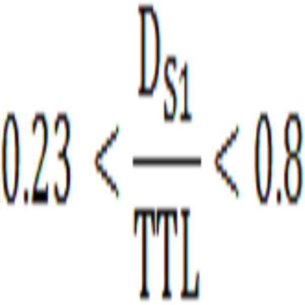
(여기서, Ds1은 상기 제 1 렌즈의 상기 제 1 방향을 향하는 면에서의 유효경, TTL은 상기 렌즈 어셈블리의 전장 길이)According to claim 1,
The first lens assembly satisfies the following [Equation 4].
[Equation 4]
(Where Ds1 is the effective diameter of the first lens facing the first direction, TTL is the total length of the lens assembly)
[수학식 5]
(여기서, f_air는 서로 오목한 면을 마주보는 상기 제 3 렌즈 및 상기 제 4 렌즈의 합성 초점거리, efl은 상기 렌즈 어셈블리의 합성 초점거리)The lens assembly of claim 1, wherein the third lens and the fourth lens satisfy the following [Equation 5].
[Equation 5]
(Where f_air is the combined focal length of the third lens and the fourth lens facing the concave surfaces of each other, efl is the combined focal length of the lens assembly)
상기 제 1 렌즈 및 상기 제 2 렌즈는 다음의 [수학식 6]을 만족하며,
[수학식 6]
상기 제 3 렌즈 및 상기 제 4 렌즈는 다음의 [수학식 7]을 만족하는 렌즈 어셈블리.
[수학식 7]
(여기서, Vd_p는 상기 제 1 렌즈 및 상기 제 2 렌즈의 아베수(Abbe's number)의 평균, Vd_n은 상기 제 3 렌즈 및 상기 제 4 렌즈의 아베수의 평균)According to claim 1,
The first lens and the second lens satisfy the following [Equation 6],
[Equation 6]
The third lens and the fourth lens is a lens assembly that satisfies the following [Equation 7].
[Equation 7]
(Where, Vd_p is the average of the Abbe's number of the first lens and the second lens, Vd_n is the average of the Abbe number of the third lens and the fourth lens)
상기 제 5 렌즈는 다음의 [수학식 8]을 만족하고,
[수학식 8]
상기 제 6 렌즈는 다음의 [수학식 9]를 만족하는 렌즈 어셈블리.
[수학식 9]
(여기서, Vd_pL은 상기 제 5 렌즈의 아베수, Vd_nL는 상기 제 6 렌즈의 아베수)According to claim 1,
The fifth lens satisfies the following [Equation 8],
[Equation 8]
The sixth lens is a lens assembly that satisfies the following [Equation 9].
[Equation 9]
(Where, Vd_pL is the Abbe number of the fifth lens, Vd_nL is the Abbe number of the sixth lens)
상기 제 1 렌즈의 유효경은 상기 제 2 렌즈의 유효경보다 크고, 상기 제 2 렌즈의 유효경은 상기 제 3 렌즈의 유효경보다 큰 렌즈 어셈블리. According to claim 1,
The lens assembly of the first lens is larger than the effective diameter of the second lens, and the effective diameter of the second lens is larger than the effective diameter of the third lens.
상기 제 5 렌즈 또는 상기 제 6 렌즈 중 적어도 하나의 렌즈에는, 적어도 한 면의 비구면이 형성된 렌즈 어셈블리.According to claim 1,
A lens assembly having at least one aspherical surface formed on at least one of the fifth lens or the sixth lens.
상기 비구면을 포함하는 상기 제 5 렌즈의 면 또는 상기 제 6 렌즈의 면 중 적어도 하나의 면은 변곡점을 포함하는 렌즈 어셈블리. According to claim 1,
At least one of the surface of the fifth lens or the surface of the sixth lens including the aspherical surface includes an inflection point.
피사체(Object) 측으로부터 상(image) 측으로 복수의 렌즈들이 순서대로 배치된 렌즈 어셈블리;
상기 렌즈 어셈블리들을 순차적으로 통과한 이미지를 검출하는 이미지 센서; 및
상기 이미지를 저장 또는 출력하는 이미지 신호 프로세서를 포함하고,
상기 렌즈 어셈블리는,
정(positive)의 굴절력을 가지고, 제 1 방향을 향한 면이 볼록한 제 1 렌즈;
정(positive)의 굴절력을 가지고, 상기 제 1 방향을 향한 면이 볼록한 제 2 렌즈;
부(negative)의 굴절력을 가지고, 상기 제 1 방향의 반대 방향을 향하는 제 2 방향을 향한 면이 오목한 제 3 렌즈;
상기 제 1 방향을 향한 면이 오목하게 형성되어, 상기 제 3 렌즈의 오목한 면과 서로 마주보도록 배치된 상기 제 4 렌즈; 및
정(positive)의 굴절력을 가지고, 상기 제 2 방향을 향한 면이 볼록한 제 5 렌즈; 를 포함하고, 상기 렌즈 어셈블리는,
다음의 [수학식 1] 및 [수학식 2]를 만족하는 전자 장치.
[수학식 1]
[수학식 2]
(여기서, TTL은 상기 렌즈 어셈블리의 전장 길이, θ는 상기 렌즈 어셈블리의 반(half) 화각, Sag_13은 상기 제 1 렌즈의 구결 표면(sagittal plane) 상의 유효거리와 제 2 렌즈의 구결 표면 상의 유효거리의 합, Y는 상기 이미지 센서의 대각선 길이의 절반) In the electronic device,
A lens assembly in which a plurality of lenses are sequentially arranged from an object side to an image side;
An image sensor that detects an image that has sequentially passed through the lens assemblies; And
And an image signal processor for storing or outputting the image,
The lens assembly,
A first lens having positive refractive power and having a convex surface facing the first direction;
A second lens having positive refractive power and having a convex surface facing the first direction;
A third lens having a negative refractive power and having a concave surface facing the second direction facing the opposite direction of the first direction;
The fourth lens having a concave surface facing the first direction and disposed to face the concave surface of the third lens; And
A fifth lens having positive refractive power and having a convex surface facing the second direction; Including, the lens assembly,
An electronic device satisfying the following [Equation 1] and [Equation 2].
[Equation 1]
[Equation 2]
(Where TTL is the full length of the lens assembly, θ is the half angle of view of the lens assembly, Sag_13 is the effective distance on the sagittal plane of the first lens and the effective distance on the supple surface of the second lens Sum of, Y is half the diagonal length of the image sensor)
부(negative)의 굴절력을 가지고, 상기 제 2 방향을 향한 면이 오목한 제 6 렌즈를 더 포함하는 것을 특징으로 하는 전자 장치.The method of claim 11,
And a negative lens having negative refractive power and having a concave surface facing the second direction.
[수학식 3]
(여기서, ET1은 상기 제 1 렌즈의 주변부(marginal portion) 중 일측 단부의 두께, ET2는 상기 제 2 렌즈의 주변부(marginal portion) 중 일측 단부의 두께, CT1은 상기 제 1 렌즈의 중심부(chief portion)의 두께, CT2는 상기 제 2 렌즈의 중심부(chief portion)의 두께)The electronic device of claim 11, wherein the first lens and the second lens satisfy the following [Equation 3].
[Equation 3]
(Where ET1 is the thickness of one end of the marginal portion of the first lens, ET2 is the thickness of one end of the marginal portion of the second lens, CT1 is the chief portion of the first lens ), CT2 is the thickness of the chief portion of the second lens)
상기 제 1 렌즈는 다음의 [수학식 4]를 만족하는 전자 장치.
[수학식 4]
(여기서, DS1은 상기 제 1 렌즈의 유효경, TTL은 상기 렌즈 어셈블리의 전장 길이)The method of claim 11,
The first lens is an electronic device satisfying the following [Equation 4].
[Equation 4]
(Where D S1 is the effective diameter of the first lens, TTL is the full length of the lens assembly)
상기 제 3 렌즈 및 상기 제 4 렌즈는 다음의 [수학식 5]을 만족하는 전자 장치.
[수학식 5]
(여기서, fair는 서로 오목한 면을 마주보는 상기 상기 제 3 렌즈 및 상기 제 4 렌즈의 합성 초점거리, efl은 상기 렌즈 어셈블리의 합성 초점거리)The method of claim 11,
The third lens and the fourth lens satisfy the following [Equation 5].
[Equation 5]
(Where fair is the combined focal length of the third lens and the fourth lens facing the concave surfaces of each other, efl is the combined focal length of the lens assembly)
상기 제 1 렌즈 및 상기 제 2 렌즈는 다음의 [수학식 6]을 만족하고,
[수학식 6]
상기 제 3 렌즈 및 상기 제 4 렌즈는 다음의 [수학식 7]을 만족하는 전자 장치.
[수학식 7]
(여기서, Vd_p는 상기 제 1 렌즈 및 상기 제 2 렌즈의 아베수(Abbe's number)의 평균, Vd_n은 상기 제 3 렌즈 및 상기 제 4 렌즈의 아베수의 평균)The method of claim 11,
The first lens and the second lens satisfy the following [Equation 6],
[Equation 6]
The third lens and the fourth lens are electronic devices satisfying the following [Equation 7].
[Equation 7]
(Where, Vd_p is the average of the Abbe's number of the first lens and the second lens, Vd_n is the average of the Abbe number of the third lens and the fourth lens)
상기 제 5 렌즈는 다음의 [수학식 8]을 만족하고,
[수학식 8]
상기 제 6 렌즈는 다음의 [수학식 9]를 만족하는 전자 장치.
[수학식 9]
(여기서, Vd_pL은 상기 제 5 렌즈의 아베수, Vd_nL는 상기 제 6 렌즈의 아베수)The method of claim 11,
The fifth lens satisfies the following [Equation 8],
[Equation 8]
The sixth lens is an electronic device satisfying the following [Equation 9].
[Equation 9]
(Where, Vd_pL is the Abbe number of the fifth lens, Vd_nL is the Abbe number of the sixth lens)
상기 제 5 렌즈 또는 상기 제 6 렌즈 중 적어도 하나의 렌즈에는, 적어도 한 면의 비구면이 형성된 전자 장치.The method of claim 11,
An electronic device having at least one aspherical surface formed on at least one of the fifth lens and the sixth lens.
상기 비구면을 포함하는 상기 제 5 렌즈의 면 또는 상기 제 6 렌즈의 면 중 적어도 하나의 면은 변곡점을 포함하는 전자 장치.
The method of claim 11,
The at least one surface of the surface of the fifth lens or the surface of the sixth lens including the aspherical surface includes an inflection point.
Priority Applications (5)
| Application Number | Priority Date | Filing Date | Title |
|---|---|---|---|
| KR1020180117887A KR20200038154A (en) | 2018-10-02 | 2018-10-02 | Lens assembly and electronic device including the same |
| PCT/KR2019/012955 WO2020071812A1 (en) | 2018-10-02 | 2019-10-02 | Lens assembly and electronic device including the same |
| US16/590,559 US11163135B2 (en) | 2018-10-02 | 2019-10-02 | Lens assembly and electronic device including the same |
| EP19868241.1A EP3803487A4 (en) | 2018-10-02 | 2019-10-02 | Lens assembly and electronic device including the same |
| CN201980065476.4A CN112789540B (en) | 2018-10-02 | 2019-10-02 | Lens assembly and electronic device including the same |
Applications Claiming Priority (1)
| Application Number | Priority Date | Filing Date | Title |
|---|---|---|---|
| KR1020180117887A KR20200038154A (en) | 2018-10-02 | 2018-10-02 | Lens assembly and electronic device including the same |
Publications (1)
| Publication Number | Publication Date |
|---|---|
| KR20200038154A true KR20200038154A (en) | 2020-04-10 |
Family
ID=69947332
Family Applications (1)
| Application Number | Title | Priority Date | Filing Date |
|---|---|---|---|
| KR1020180117887A KR20200038154A (en) | 2018-10-02 | 2018-10-02 | Lens assembly and electronic device including the same |
Country Status (5)
| Country | Link |
|---|---|
| US (1) | US11163135B2 (en) |
| EP (1) | EP3803487A4 (en) |
| KR (1) | KR20200038154A (en) |
| CN (1) | CN112789540B (en) |
| WO (1) | WO2020071812A1 (en) |
Families Citing this family (3)
| Publication number | Priority date | Publication date | Assignee | Title |
|---|---|---|---|---|
| CN111624745B (en) * | 2020-07-28 | 2020-10-27 | 常州市瑞泰光电有限公司 | Image pickup optical lens |
| CN115097599B (en) * | 2022-06-17 | 2023-07-14 | 安徽光智科技有限公司 | Wide-angle infrared lens for boiler |
| CN116430549B (en) * | 2023-04-06 | 2024-01-12 | 广东旭业光电科技股份有限公司 | Telephoto lens and electronic equipment |
Family Cites Families (24)
| Publication number | Priority date | Publication date | Assignee | Title |
|---|---|---|---|---|
| JPS5817929B2 (en) | 1975-06-14 | 1983-04-11 | オリンパス光学工業株式会社 | Daiko Keihishiyashin Lens |
| JP3964533B2 (en) | 1998-03-19 | 2007-08-22 | マミヤ・デジタル・イメージング株式会社 | Medium telephoto lens |
| JP2000171701A (en) | 1998-09-30 | 2000-06-23 | Fuji Photo Optical Co Ltd | Deformable gauss type lens |
| JP2007333966A (en) * | 2006-06-14 | 2007-12-27 | Sony Corp | Imaging lens and imaging apparatus |
| CN100565269C (en) * | 2006-10-09 | 2009-12-02 | 亚洲光学股份有限公司 | Wide-angle lens |
| KR101679289B1 (en) * | 2009-07-07 | 2016-11-24 | 삼성전자 주식회사 | Zoom lens and imaging optical device having the same |
| JP5716986B2 (en) | 2010-02-25 | 2015-05-13 | 株式会社ニコン | Lens system and optical equipment |
| JP5716995B2 (en) | 2011-04-11 | 2015-05-13 | 株式会社ニコン | Optical system and imaging apparatus having this optical system |
| TWI438471B (en) * | 2011-08-24 | 2014-05-21 | Largan Precision Co Ltd | Optical image capturing lenses |
| JP5963360B2 (en) * | 2012-11-21 | 2016-08-03 | カンタツ株式会社 | Imaging lens |
| JP6021617B2 (en) * | 2012-12-05 | 2016-11-09 | カンタツ株式会社 | Imaging lens |
| CN107748432A (en) | 2013-07-04 | 2018-03-02 | 核心光电有限公司 | Small-sized focal length lens external member |
| JP6191820B2 (en) | 2013-10-04 | 2017-09-06 | コニカミノルタ株式会社 | Imaging lens, imaging device, and portable terminal |
| KR101652849B1 (en) | 2013-12-19 | 2016-08-31 | 삼성전기주식회사 | Lens module |
| JP6393872B2 (en) * | 2014-08-27 | 2018-09-26 | カンタツ株式会社 | Imaging lens |
| KR102380230B1 (en) * | 2015-03-18 | 2022-03-30 | 삼성전자주식회사 | Imaging lens and imaging apparatus including the same |
| KR101762006B1 (en) | 2015-07-24 | 2017-07-26 | 삼성전기주식회사 | Optical system and mobile device including a plurality of optical systems with different field of view |
| US10185123B2 (en) | 2015-10-22 | 2019-01-22 | Apple Inc. | Lens system |
| KR102564885B1 (en) * | 2015-11-02 | 2023-08-08 | 삼성전자주식회사 | Short focus lens and optical device with the same |
| KR101834729B1 (en) * | 2016-05-04 | 2018-03-06 | 주식회사 코렌 | Wide angle lens and imaging device having the same |
| JP6849350B2 (en) | 2016-09-05 | 2021-03-24 | キヤノン株式会社 | Optical system and optical equipment with it |
| KR20180068585A (en) * | 2016-12-14 | 2018-06-22 | 삼성전자주식회사 | Optical lens assembly and method of forming an image using the same |
| TWI637207B (en) | 2017-09-22 | 2018-10-01 | 大立光電股份有限公司 | Imaging lens assembly, image capturing unit and electronic device |
| CN110018557B (en) * | 2019-05-24 | 2024-04-02 | 浙江舜宇光学有限公司 | Image pickup lens |
-
2018
- 2018-10-02 KR KR1020180117887A patent/KR20200038154A/en not_active Application Discontinuation
-
2019
- 2019-10-02 WO PCT/KR2019/012955 patent/WO2020071812A1/en unknown
- 2019-10-02 CN CN201980065476.4A patent/CN112789540B/en active Active
- 2019-10-02 EP EP19868241.1A patent/EP3803487A4/en active Pending
- 2019-10-02 US US16/590,559 patent/US11163135B2/en active Active
Also Published As
| Publication number | Publication date |
|---|---|
| CN112789540A (en) | 2021-05-11 |
| US11163135B2 (en) | 2021-11-02 |
| EP3803487A4 (en) | 2021-08-04 |
| CN112789540B (en) | 2022-12-06 |
| US20200103619A1 (en) | 2020-04-02 |
| WO2020071812A1 (en) | 2020-04-09 |
| EP3803487A1 (en) | 2021-04-14 |
Similar Documents
| Publication | Publication Date | Title |
|---|---|---|
| US11885943B2 (en) | Lens assembly and electronic device including the same | |
| CN111566536B (en) | Optical lens assembly and electronic device including the same | |
| KR20170098064A (en) | Optical lens assembly and electronic apparatus having the same | |
| KR20180068585A (en) | Optical lens assembly and method of forming an image using the same | |
| KR20180015485A (en) | Optical lens assembly and electronic apparatus having the same | |
| US11927726B2 (en) | Optical lens system and electronic device including the same | |
| KR20180005464A (en) | Optical lens assembly and electronic apparatus having the same | |
| CN112789540B (en) | Lens assembly and electronic device including the same | |
| US20200241250A1 (en) | Lens assembly and electronic device including the same | |
| US20240056667A1 (en) | Lens assembly and electronic device including the same | |
| US20230204907A1 (en) | Lens assembly and electronic device including the same | |
| US20230176336A1 (en) | Lens assembly and electronic device including the same | |
| US20220269048A1 (en) | Lens assembly and electronic apparatus including the same | |
| EP4350412A1 (en) | Lens assembly and electronic device including same | |
| US20230176260A1 (en) | Lens assembly and electronic device including the same | |
| EP4318070A1 (en) | Lens assembly and electronic device comprising same | |
| KR20230115847A (en) | Lens assembly and electronic device including the same | |
| US20240126054A1 (en) | Lens assembly and electronic device including same | |
| EP4354194A1 (en) | Lens assembly and electronic device including same | |
| KR102651598B1 (en) | Lens assembly and electronic device including the same | |
| US20230204924A1 (en) | Lens assembly and electronic device including the same | |
| KR20230100539A (en) | Lens assembly and electronic device including the same | |
| EP4239387A1 (en) | Lens assembly and electronic device comprising same | |
| US20220214526A1 (en) | Lens assembly and electronic apparatus including the same | |
| KR20230096794A (en) | Lens assembly and electronic device including the same |
Legal Events
| Date | Code | Title | Description |
|---|---|---|---|
| E902 | Notification of reason for refusal |