KR20200037727A - A Foldable Display Apparatus - Google Patents
A Foldable Display Apparatus Download PDFInfo
- Publication number
- KR20200037727A KR20200037727A KR1020190094390A KR20190094390A KR20200037727A KR 20200037727 A KR20200037727 A KR 20200037727A KR 1020190094390 A KR1020190094390 A KR 1020190094390A KR 20190094390 A KR20190094390 A KR 20190094390A KR 20200037727 A KR20200037727 A KR 20200037727A
- Authority
- KR
- South Korea
- Prior art keywords
- display device
- hinge
- sliding
- support surface
- folded
- Prior art date
Links
Images


Classifications
-
- G—PHYSICS
- G09—EDUCATION; CRYPTOGRAPHY; DISPLAY; ADVERTISING; SEALS
- G09F—DISPLAYING; ADVERTISING; SIGNS; LABELS OR NAME-PLATES; SEALS
- G09F9/00—Indicating arrangements for variable information in which the information is built-up on a support by selection or combination of individual elements
- G09F9/30—Indicating arrangements for variable information in which the information is built-up on a support by selection or combination of individual elements in which the desired character or characters are formed by combining individual elements
- G09F9/301—Indicating arrangements for variable information in which the information is built-up on a support by selection or combination of individual elements in which the desired character or characters are formed by combining individual elements flexible foldable or roll-able electronic displays, e.g. thin LCD, OLED
-
- G—PHYSICS
- G06—COMPUTING; CALCULATING OR COUNTING
- G06F—ELECTRIC DIGITAL DATA PROCESSING
- G06F1/00—Details not covered by groups G06F3/00 - G06F13/00 and G06F21/00
- G06F1/16—Constructional details or arrangements
- G06F1/1613—Constructional details or arrangements for portable computers
- G06F1/1615—Constructional details or arrangements for portable computers with several enclosures having relative motions, each enclosure supporting at least one I/O or computing function
- G06F1/1616—Constructional details or arrangements for portable computers with several enclosures having relative motions, each enclosure supporting at least one I/O or computing function with folding flat displays, e.g. laptop computers or notebooks having a clamshell configuration, with body parts pivoting to an open position around an axis parallel to the plane they define in closed position
-
- G—PHYSICS
- G06—COMPUTING; CALCULATING OR COUNTING
- G06F—ELECTRIC DIGITAL DATA PROCESSING
- G06F1/00—Details not covered by groups G06F3/00 - G06F13/00 and G06F21/00
- G06F1/16—Constructional details or arrangements
- G06F1/1613—Constructional details or arrangements for portable computers
- G06F1/1633—Constructional details or arrangements of portable computers not specific to the type of enclosures covered by groups G06F1/1615 - G06F1/1626
- G06F1/1637—Details related to the display arrangement, including those related to the mounting of the display in the housing
- G06F1/1641—Details related to the display arrangement, including those related to the mounting of the display in the housing the display being formed by a plurality of foldable display components
Abstract
Description
본 발명은 폴더블 디스플레이를 이용해 접힘 및 펼침 상태와 무관하게 전 방향에 대한 화면 표시 및 소리 발생을 동시에 구현하며 몸체의 접힘시 형성되는 가변 공간에 스피커를 적용해 저음 발생을 증대시켜 폴더블 기기의 휴대 특성과 AI 스피커 기능 및 영상표시장치 기능을 모두 갖는 폴더블 영상표시장치에 관한 것이다.The present invention simultaneously implements screen display and sound generation in all directions irrespective of the folded and unfolded state using a foldable display, and applies speakers to a variable space formed when the body is folded to increase the generation of low-pitched sounds. The present invention relates to a foldable video display device having both portable characteristics, AI speaker function, and video display device function.
판상 고정형의 스마트폰을 대체할 수 있는 영상표시장치로서 e-INK가 적용된 전자종이, 플렉시블 OLED 및 마이크로 LED와 같이 접힘이 가능한 플렉시블 디스플레이가 적용된 다양한 폴더블 영상표시장치가 제시되고 있다.As a video display device that can replace a plate-type smartphone, a variety of foldable video display devices have been proposed to which e-INK-applied electronic paper, flexible OLEDs, and flexible displays that can be folded, such as micro LEDs, are applied.
이러한 폴더블 영상표시장치는 접히는 부위에서의 힌지 적용 유무에 따라 무 힌지 방식과 힌지 적용 방식으로 구분되며 다수의 특허(대한민국 특허 10-0125125, 10-0017875, 10-0106358, 10-0129704, 10-0017606)가 제시되었다.The foldable video display device is divided into a hingeless method and a hinged application method depending on whether a hinge is applied at a folding part, and a number of patents (Korea Patents 10-0125125, 10-0017875, 10-0106358, 10-0129704, 10- 0017606).
상기의 제시된 특허들 중 본 발명인에 의해 제시된 대한민국 특허 10-0106358에는 삼각기둥 접힘 상태를 가능케 하는 실시예가 포함되어있으나 접힘 상태시 가변 공간이 형성되지 않고, 힌지 축을 기준으로 회전 펼침되는 덮개판이 제어부의 구성품들을 적용할 수 있는 내부공간을 확보할 수 없는 두께문제, 힌지 축 부위에서의 불연속 노출부위 발생 문제와 더불어 펼침 상태시 중간 부분의 삼각기둥 형태가 돌출 존재하는 문제점이 존재한다.Among the proposed patents, the Republic of Korea Patent No. 10-0106358 proposed by the present inventor includes an embodiment that enables a triangular prism to be folded, but a variable space is not formed in the folded state, and a cover plate that is rotated and unfolded based on the hinge axis of the controller In addition to the thickness problem that cannot secure the internal space to which components can be applied, and the problem of the occurrence of discontinuous exposed areas at the hinge axis, there is a problem that the shape of the triangular prism in the middle part protrudes when unfolded.
이와 별도로 압전소자 또는 박막 스피커를 이용하는 많은 특허 (대한민국 특허 10-1788470) 들이 제시되었으며 OLED를 이용한 고가의 TV에는 EXCITOR를 이용해 OLED를 진동시켜 플렉시블 디스플레이 자체가 소리를 내는 제품이 출시되고 있다.Separately, many patents (Korean Patent 10-1788470) using piezoelectric elements or thin-film speakers have been proposed, and products that make the flexible display itself sound by vibrating the OLED using EXCITOR are being released on expensive TVs using OLEDs.
또한 음성인식 기능과 함께 네트워크 기능이 적용된 AI 스피커 제품들이 스마트폰과 별도의 제품으로 출시되고 있다.In addition, AI speaker products with network functions along with voice recognition are being released as separate products from smartphones.
본 발명이 이루고자하는 기술적 과제는 첫째, 스마트폰을 포함하는 영상표시장치가 거치 상태에 영향을 받지 않으며 AI 스피커 기능을 수행할 수 있도록 전방향에 대한 음성 및 영상 인식과 함께 전 방향에 대한 화면 표시 및 소리 출력이 가능하도록 하고자 한다.The technical problem to be achieved by the present invention is first, the video display device including the smart phone is not affected by the mounting state and displays the screen for all directions along with voice and video recognition for all directions to perform the AI speaker function. And to enable sound output.
둘째, 접힘 및 펼침 수행시 힌지 축 부위에서 발생하는 불연속 노출부위 및 플렉시블 디스플레이 끝단의 미끄럼 이동을 감소시키고자 한다.Second, it is intended to reduce the sliding movement of the end of the flexible display and the discontinuous exposed portion generated at the hinge axis when performing folding and unfolding.
셋째, 사용자가 접힘 및 펼침상태 전환을 선택적으로 통제할 수 있도록 하고자 한다.Third, it is intended to allow the user to selectively control the folding and unfolding state transitions.
넷째, 접힘 또는 펼침 상태에서 낙하 되어도 자체적으로 낙하 충격을 흡수할 수 있도록 하고자 한다.Fourth, it is intended to be able to absorb the drop impact on its own even if it falls in the folded or unfolded state.
다섯째, 탈부착 베터리 적용이 가능하도록 하고자 한다.Fifth, it is intended to enable the application of removable batteries.
여섯째, 손가락을 이용한 터치조작 없이 그립하고 있는 손바닥을 이용한 네비게이션 조작이 가능케 하고자 한다.Sixth, it is intended to enable a navigation operation using a palm that is being gripped without a touch operation using a finger.
상기 기술적과제를 달성하기 위하여, 본 발명의 폴더블 영상표시장치는 제어부, 접힘 및 펼침이 가능하며 접힘 상태시 평면을 형성하는 화면 표시면 반대 면의 접착면 일부분이 소리 발생을 위한 비접착 영역인 진동판 영역을 갖는 플렉시블 디스플레이 및 플렉시블 디스플레이가 고정 또는 지지되고 접힘 및 펼침이 가능한 몸체를 포함하여 구성된다.In order to achieve the above technical task, the foldable image display device of the present invention is a control unit, which can be folded and unfolded, and a portion of an adhesive surface opposite to a screen display surface forming a flat surface when folded is a non-adhesive area for sound generation. The flexible display having the diaphragm area and the flexible display are fixed or supported, and include a body that can be folded and unfolded.
몸체는 제어부 및 베터리의 적용을 위한 내부공간을 갖으며 접힘시 형성되고 펼침시 사라지는 가변 공간을 형성한다.The body has an internal space for the application of the control unit and the battery and forms a variable space that is formed when folded and disappears when unfolded.
진동판 영역은 원형 또는 타원형의 비접착 영역을 이루며The diaphragm area forms a circular or elliptical non-adhesive area,
제어부에 연결되어 구동되는 진동 발생기에 의해 진동되며 화면 표시면의 전 방향(Front) 측으로 소리를 발생시킨다.It is vibrated by a vibration generator that is connected to the control unit and generates sound in the front side of the screen display.
화면 표시면 반대 측 몸체의 일면에는 가변 공간 측을 향하여 스피커가 적용된다.A speaker is applied to the side of the body opposite the screen display surface toward the variable space.
가변 공간은 원기둥, 삼각기둥, 사각기둥, 오각기둥 또는 육각기둥 중 어느 하나의 형상을 이루며 접힘이 이루어지는 접힘 축의 양측 끝단 부분은 개방 형성되어있는 특징을 갖는다.The variable space has a shape of any one of a cylindrical, triangular, quadrangular, pentagonal, or hexagonal column, and the ends of both ends of the folding shaft, which are folded, have an open shape.
몸체는 플렉시블 디스플레이의 일측 끝단이 고정 또는 지지되며 모서리 부분에 힌지 관련 형상이 적용되어있는 제1몸체와 제3몸체 및 플렉시블 디스플레이의 중간 부분이 고정 또는 지지되며 일측 모서리가 제1몸체에 힌지 결합되고 반대편 일측 모서리는 제3몸체에 힌지 결합되는 제2몸체를 포함하여 구성되며 제1몸체와 제3몸체에는 플렉시블 디스플레이의 일측 끝단 화면 표시면 반대 측 면이 접착 고정되는 디스플레이 접착면1이 일면에 반영되어 있고 힌지 축과 수직인 방향으로 미끄럼 이동 가능한 상태로 조립되는 미끄럼 이동판이 적용된다.The body is fixed or supported at one end of the flexible display, and the first body and the third body to which the hinge-related shape is applied to the corner portion are fixed or supported, and one edge is hinged to the first body. The opposite side edge comprises a second body hinged to the third body, and the
미끄럼 이동판의 디스플레이 접착면1에는 진동 발생기의 고정을 위한 진동 발생기 적용구1이 관통 또는 함몰 형성되어 있다.On the display
제2몸체에는 플렉시블 디스플레이의 중간부분 화면표시면 반대 측 면이 접착 고정되는 면인 디스플레이 접착면2가 일면에 반영되어있고 반대편 일면은 제2몸체의 일면에 접착 고정 또는 조립되는 고정판이 적용되며 디스플레이 접착면2에는 진동 발생기의 고정을 위한 진동 발생기 적용구2가 관통 또는 함몰 형성되어 있다.In the second body, the display adhesive surface 2, which is the surface on which the opposite side of the display portion of the flexible display is adhered and fixed, is reflected on one surface, and the other side is applied with a fixed plate that is adhesively fixed or assembled to one surface of the second body and the display is adhered. On the surface 2, the vibration generator application port 2 for fixing the vibration generator is formed through or recessed.
제1몸체 및 제3몸체에는 미끄럼 이동판의 미끄럼 이동 및 지지를 위해 화면 표시면의 반대면 측 일면으로부터 미끄럼 이동판의 두께 깊이로 함몰 형성된 미끄럼 이동판 지지면1이 형성되어 있고 미끄럼 이동판 지지면1에는 접힘 및 펼침 수행시 미끄럼 이동판 지지면 측으로 돌출된 진동 발생기 또는 진동 발생기 적용구1와 미끄럼 이동판 지지면1 사이의 간섭 방지를 위해 진동 발생기 지지 장공이 형성되어있다.For the first body and the third body, a sliding
제2몸체에는 화면 표시면의 반대면 측 일면으로부터 고정판의 두께 깊이로 함몰 형성된 고정판 접착면이 형성되어 있고, 고정판 접착면에는 고정판 접착면 측으로 돌출된 진동 발생기 또는 진동 발생기 적용구2와의 간섭 방지를 위해 진동 발생기 고정구가 형성되어 있다.The second body is formed with a fixed plate adhesive surface recessed to a thickness depth of the fixed plate from one side of the opposite side of the screen display surface, and the fixed plate adhesive surface prevents interference with the vibration generator or vibration generator application port 2 protruding toward the fixed plate adhesive surface. Weihai vibration generator fixture is formed.
제1몸체 및 제3몸체의 내부공간에는 접힘 및 펼침시 내부공간 측으로 돌출된 진동 발생기 또는 진동 발생기 적용구1과 내부공간 적용 구성품 사이의 간섭 방지를 위해 돌출된 진동 발생기 또는 진동 발생기 적용구1의 미끄럼 이동 방향 전방에 전방 슬라이딩 영역1 및 전방 슬라이딩 영역2 공간이 적용되고 후방에는 후방 슬라이딩 영역1 및 후방 슬라이딩 영역2 공간이 적용된다.In the inner spaces of the first body and the third body, the protruded vibration generator or vibration
미끄럼 이동판에는 카메라 및 마이크가 적용되어 있다.A camera and a microphone are applied to the sliding plate.
상기 몸체의 제 1실시예는 제1몸체 및 제3몸체의 힌지 축에 수직인 일부분 형상은 플렉시블 디스플레이의 화면표시면 반대측 면이 직접 또는 간접 고정되거나 지지되는 평면인 표시장치 지지면1, 표시장치 지지면1의 반대측 노출면을 이루는 몸체 내측면1, 표시장치 지지면1과 접하는 상태로 힌지 원주면을 따라 곡면 형성된 힌지 원주면1, 힌지 원주면1과 접하거나 또는 연결된 상태로 표시장치 지지면1의 반대측 면에 위치되는 접힘 지지면1 및 접힘 지지면1의 끝단과 몸체 내측면1을 연결하여 형성되며 접힘 지지면1에 접하지 않는 접힘 지지면2를 포함하며 이에 대응하는 제2몸체의 힌지 축에 수직인 일부분 형상은 플렉시블 디스플레이의 평면 펼침시 표시장치 지지면1과 동일 평면을 이루는 표시장치 지지면2, 표시장치 지지면2의 반대측 노출면을 이루는 몸체 내측면2, 일측 끝단은 몸체 내측면2의 힌지 측 끝단에 연결되고 반대측 끝단은 제1몸체와 제2몸체 또는 제3몸체와 제2몸체의 접힘 상태시 제2몸체에 위치되는 제1몸체 또는 제3몸체의 접힘 지지면2에 접촉되거나 마주 보며 위치되는 접힘 지지면4 및 제1몸체와 제2몸체 또는 제3몸체와 제2몸체의 접힘 상태시 제2몸체의 힌지 측에 위치되는 제1몸체 또는 제3몸체의 접힘 지지면1의 연장면에 해당되는 접힘 지지면6을 포함하는 형상을 갖는다.In the first embodiment of the body, the shape of a portion perpendicular to the hinge axes of the first body and the third body is a display
상기 제 1실시예에서 제2몸체의 힌지 축선상 다른 위치에 수직인 일부분 형상은 표시장치 지지면2, 몸체 내측면2, 표시장치 지지면2와 접하는 상태로 힌지 원주면을 따라 곡면 형성된 한쌍의 마주보며 위치되는 힌지 원주면2, 힌지 원주면2와 접하거나 또는 연결된 상태로 표시장치 지지면2의 반대측 면을 이루고 마주보며 위치되는 한쌍의 접힘 지지면3 및 접힘 지지면3의 끝단과 몸체 내측면2를 연결하여 형성되며 접힘 지지면3에 접하지 않고 마주보며 위치되는 한쌍의 접힘 지지면4를 포함하고 이에 대응하는 제1몸체 및 제3몸체의 힌지 축에 수직인 일부분 형상은 표시장치 지지면1, 접힘 지지면2, 제1몸체와 제2몸체 또는 제3몸체와 제2몸체의 접힘 상태시 제1몸체 또는 제3몸체의 내측에 위치되는 제2몸체의 접힘 지지면3의 연장면에 해당되는 접힘 지지면5 및 몸체 내측면1을 포함하는 형상을 갖는다.In the first embodiment, the partial shape perpendicular to the other position on the hinge axis of the second body is a pair of curved surfaces along the circumferential surface of the hinge in contact with the display device support surface 2, the body inner surface 2, and the display device support surface 2. Ends and bodies of a pair of folded support surfaces 3 and folded support surfaces 3 facing and forming opposite sides of the display device support surface 2 in contact with or connected to the hinge circumferential surface 2, the hinge circumferential surface 2, which are positioned facing each other Partial shape perpendicular to the hinge axis of the first body and the third body including a pair of folded support surfaces 4 formed by connecting the side surfaces 2 and facing each other without facing the folded support surface 3 and supporting the
상기 몸체의 제 2실시예는 제1몸체 및 제3몸체의 힌지 축에 수직인 일부분 형상은 플렉시블 디스플레이의 화면표시면 반대측 면이 직접 또는 간접 고정되거나 지지되는 평면인 표시장치 지지면1, 표시장치 지지면1과 접하는 상태로 힌지 원주면을 따라 곡면 형성된 힌지 원주면1, 표시장치 지지면1의 반대측 노출면을 이루며 힌지 원주면1에 접하는 몸체 내측면1을 포함하며 이에 대응하는 제2몸체의 힌지 축에 수직인 일부분 형상은 플렉시블 디스플레이의 평면 펼침시 표시장치 지지면1과 동일 평면을 이루는 표시장치 지지면2, 표시장치 지지면2의 반대측 노출면을 이루는 몸체 내측면2 및 표시장치 지지면2와 몸체 내측면2를 연결하고 제1몸체와 제2몸체 또는 제3몸체와 제2몸체의 접힘 상태시 제2몸체의 힌지 측에 위치되는 제1몸체 또는 제3몸체의 몸체 내측면1에 접촉되거나 마주보며 위치되는 접힘 지지면6을 포함하는 형상을 갖는다.In the second embodiment of the body, the shape of a portion perpendicular to the hinge axis of the first body and the third body is a display
상기 제 2실시예에서 제2몸체의 힌지 축선상 다른 위치에 수직인 일부분 형상은 표시장치 지지면2, 몸체 내측면2, 표시장치 지지면2와 접하는 상태로 힌지 원주면을 따라 곡면 형성된 한쌍의 마주보며 위치되는 힌지 원주면2 및 표시장치 지지면2의 반대측 노출면을 이루며 힌지 원주면2에 접하는 몸체 내측면2를 포함하며 이에 대응하는 제1몸체 및 제3몸체의 힌지 축에 수직인 일부분 형상은 표시장치 지지면1, 몸체 내측면1 및 표시장치 지지면1과 몸체 내측면1을 연결하고 제1몸체와 제2몸체 또는 제3몸체와 제2몸체의 접힘 상태시 제1몸체 또는 제3몸체의 내측에 위치되는 제2몸체의 몸체 내측면2에 접촉되거나 마주보며 위치되는 접힘 지지면5를 포함하는 형상을 갖는다.In the second embodiment, the partial shape perpendicular to the other position on the hinge axis of the second body is a pair of curved surfaces along the circumferential surface of the hinge in contact with the display device support surface 2, the body inner surface 2, and the display device support surface 2. A part of the hinge circumferential surface 2 and the inner surface 2 of the body facing the hinge circumferential surface 2 forming opposite surfaces of the hinge circumferential surface 2 and the display device support surface 2 facing each other, and corresponding to a portion perpendicular to the hinge axis of the corresponding first and third bodies The shape connects the display
상기 제 1실시예 및 제 2실시예에서 제1몸체 및 제3몸체는 몸체 내측면1의 힌지 측 반대편 끝단 부분으로 부터 표시장치 지지면1 측을 향하여 형성된 경사면1 및 경사면1과 표시장치 지지면1을 연결하며 힌지 반대 측 바깥 노출면을 이루는 그립면1을 포함하는 형상을 갖는다.In the first and second embodiments, the first body and the third body are
상기 제 1실시예 및 제 2실시예에서 제1몸체 및 제3몸체의 그립면1에는 그립면1의 표시장치 지지면1 측 상단 모서리 부분이 힌지 측 방향으로 개방되어 형성된 슬라이딩 개방구가 형성될 수도 있다.In the first and second embodiments, the first body and the third body of the
상기 제 1실시예 및 제 2실시예에서 제1몸체 및 제3몸체에는 플렉시블 디스플레이의 모서리면 노출 방지를 위해 표시장치 지지면1의 힌지 축과 수직인 양측 모서리 끝단 부분에 표시장치 지지면1로부터 플렉시블 디스플레이 두께 이상으로 돌출 형성된 베젤형상1이 형성되어 있고 제2몸체에는 표시장치 지지면2에 위치하는 플렉시블 디스플레이의 양측 모서리 부분 노출 방지를 위해 표시장치 지지면2로부터 플렉시블 디스플레이 두께 이상으로 돌출 형성된 베젤형상2가 형성되어 있다.In the first and second embodiments, the first body and the third body are provided from the display
베젤형상1의 힌지 측 끝단 모서리에는 완전 평면 펼침 상태시 힌지 축과 일치하지 않고 그립면1측을 향하여 끝단부가 간섭 방지 거리를 유지하며 그 끝단에는 경사면이 반영된 베젤 간섭 방지부1가 형성되어 있고 베젤형상2의 힌지 측 끝단 모서리는 완전 평면 펼침 상태시 힌지 축과 일치하지 않고 반대 편의 힌지 축을 향하여 끝단부 길이가 감소된 간섭 방지 거리를 유지하며 그 끝단에는 경사면이 반영된 베젤 간섭 방지부2가 형성되어 있다.At the edge of the hinge side end of the
상기 제 1실시예에서 제1몸체 및 제3몸체에는 제2몸체와의 전기적 연결을 수행하는 플렉시블 기판의 경유 경로 확보를 위해 접힘 지지면2의 일부를 관통해 형성된 경로 관통구1가 형성되어 있고 제2몸체에는 경로 관통구1에 대응하여 접힘 지지면4의 일부를 관통해 형성된 경로 관통구2가 형성되어 있다.In the first embodiment, in the first body and the third body, a path through-
상기 제 2실시예에서 제1몸체 및 제3몸체에는 힌지 원주면1의 반경보다 제1몸체 또는 제3몸체와 제2몸체를 경유하는 플렉시블 기판의 두께 이상의 반경이 감소된 반경을 갖는 기판 경유 원주면1, 기판 경유 원주면1에 연장되어 경유하는 플렉시블 기판의 하부면을 지지하는 기판 경유 상부면1, 기판 경유 원주면1에 연장되어 접힘 지지면1에 대응하는 면을 이루는 기판 경유 하부면1 및 기판 경유 상부면1과 기판 경유 하부면1을 연결하는 적용면을 포함하여 구성되는 기판 경유 지지대가 힌지 축에 1개 이상 적용되고 기판 경유 지지대의 적용을 위해 기판 경유 지지대에 대응하는 적용 형상을 갖는 기판 지지대 적용부 형상이 반영되어 있으며 제2몸체에는 표시장치 지지면2에 위치하는 접힘 지지면6 끝단 부분에 기판 경유홈이 형성되어 있다.In the second embodiment, the first body and the third body have a radius through which the radius of the thickness of the flexible substrate passing through the first body or the third body and the second body is reduced than the radius of the
상기 제 1실시예 및 제 2실시예에서 제1몸체 및 제3몸체에는 힌지 축과 수직인 방향으로 미끄럼 이동 가능한 상태로 조립되는 미끄럼 이동판 및 탄성력을 작용시키는 탄성부재가 조립 적용되고, 미끄럼 이동판에는 플렉시블 디스플레이의 일측 끝단 화면표시면 반대 측 면이 접착 고정되고 표시장치 지지면1과 동일 평면을 유지하는 디스플레이 접착면1 및 디스플레이 접착면1의 반대면 일측 일부분이 돌출 형성된 탄성력 작용면이 형성되어 있으며 탄성부재의 일측은 지지되고 반대측 자유단은 탄성력 작용면에 접촉되어 힌지 축과 수직인 방향으로 플렉시블 디스플레이의 일측 끝단에 탄성력을 작용시키는 특징을 갖는다.In the first and second embodiments, the first body and the third body are assembled with a sliding plate and an elastic member that acts as an elastic force to be assembled in a sliding state in a direction perpendicular to the hinge axis, and sliding. On the plate, the surface opposite to the display surface of one end of the flexible display is adhesively fixed, and an elastic force acting surface formed by protruding a portion of the display
미끄럼 이동판은 제1몸체 또는 제3몸체에 미끄럼 지지될 수 있도록 디스플레이 접착면1의 반대편 면의 힌지 축 방향에 수직하는 양측 모서리 부분에 미끄럼 돌출 지지부가 형성되어있고 미끄럼 돌출 지지부의 일면에는 제1몸체 또는 제3몸체에 대한 미끄럼 이동판의 미끄럼 고정 기능을 수행할 수 있도록 미끄럼 이동판 고정 장공 형상이 미끄럼 이동 방향의 양측 끝단에 각각 형성되어 있다.The sliding plate is provided with sliding protrusions at both corners perpendicular to the hinge axis direction of the opposite side of the display
미끄럼 이동판은 디스플레이 접착면1의 힌지 측 끝단에 개방 형성된 다수의 미끄럼 이동판 개방부 및 힌지 축에 수직인 방향에 위치하는 플렉시블 디스플레이의 끝단이 화면표시면 밖으로 돌출되지 않도록 디스플레이 접착면1로 부터 플렉시블 디스플레이의 두께 이상으로 돌출된 미끄럼 이동판 돌출부1가 형성되어 있다.The sliding plate is from the display
미끄럼 이동판의 힌지 반대측 부분에는 전방 카메라 및 포토 센서가 적용되어 있다.On the opposite side of the sliding plate, the front camera and photo sensor are applied.
상기 제 1실시예 및 제 2실시예에서 제2몸체에는 플렉시블 디스플레이의 중간부분 화면표시면 반대 측 면이 접착 고정되는 면인 디스플레이 접착면2가 일면에 반영되어있고 반대편 일면은 디스플레이 접착면2가 표시장치 지지면2와 동일 평면이 유지되도록 제2몸체의 일면에 접착 고정 또는 조립되는 고정판이 적용된다.In the first and second embodiments, the second body is reflected on one side of the display adhesive surface 2, which is the surface on which the opposite side of the flexible display display is fixed and the opposite side is displayed on one surface, and the opposite side is displayed on the
상기 제 1실시예 및 제 2실시예에서 그립면1에 슬라이딩 개방구가 형성되지 않는 제1몸체 및 제3몸체에는 미끄럼 이동판의 미끄럼 이동 및 지지를 위해 표시장치 지지면1 측 일면으로부터 몸체 내측면1 측으로 미끄럼 이동판의 두께 깊이로 함몰 형성된 미끄럼 이동판 지지면1이 형성되어 있으며 베젤형상1 내측 둘레 부분과 미끄럼 이동판 지지면1 사이에는 플렉시블 디스플레이의 화면 표시면 높이와 일치되는 일면인 베젤커버 접착면1이 형성되어있고, 제2몸체에는 표시장치 지지면2 측 일면으로부터 몸체 내측면2 측으로 고정판의 두께 깊이로 함몰 형성된 고정판 접착면이 형성되어 있으며 베젤형상2 내측 둘레 부분과 고정판 접착면 사이에는 플렉시블 디스플레이의 화면 표시면 높이와 일치되는 일면인 베젤커버 접착면2이 형성되어 있다.In the first and second embodiments, the first body and the third body in which the sliding openings are not formed on the
상기 제 1실시예 및 제 2실시예에서 그립면1에 슬라이딩 개방구가 형성되지 않는 제1몸체 및 제3몸체에는 화면 표시면 측 중앙부분과 힌지 축 부분이 개방된 판상 형태를 갖고 플렉시블 디스플레이의 화면 표시면 측 일측 끝단 둘레를 미끄럼 이동 가능한 상태로 눌러주며 베젤형상1의 내측 둘레 및 베젤커버 접착면1에 고정되는 개방형 베젤커버1이 조립 적용되고, 제2몸체에는 플렉시블 디스플레이의 힌지 축에 수직인 중간 모서리 부분을 덮어주며 플렉시블 디스플레이의 화면 표시면 및 베젤커버 접착면2에 접착 고정되는 한쌍의 베젤커버2가 적용된다.In the first and second embodiments, the first body and the third body, in which the sliding openings are not formed on the
상기 제 1실시예 및 제 2실시예에서 제1몸체 및 제3몸체에는 탄성부재 및 탄성력 작용면이 적용될 수 있도록 형성된 탄성부재 적용부 및 제어부 구성품들이 적용되며 탄성부재 적용부와 분리되어 형성된 내부공간1이 형성되어 있으며 제2몸체에는 제어관련 구성품들이 적용되는 내부공간2가 형성되어 있다.In the first and second embodiments, the first member and the third body are applied with an elastic member application part and a control component formed so that an elastic member and an elastic force acting surface can be applied, and an inner space formed separately from the elastic
상기 제 1실시예 및 제 2실시예에서 그립면1에 슬라이딩 개방구가 형성되는 제1몸체 및 제3몸체에는 표시장치 지지면1이 개방 형성된 측으로 적용된 미끄럼 이동판의 이탈 방지 및 미끄럼 고정 상태 유지를 위해 미끄럼 이동판 고정 장공 측으로 끝단 돌출 부분이 걸림 될 수 있도록 내부공간1의 벽면을 관통해 적용되는 1개 이상의 미끄럼 고정 가이드가 적용되며 미끄럼 이동판의 미끄럼 돌출 지지부에 대한 밀착 지지를 수행할 수 있도록 내부공간1의 내측 벽면 중에서 힌지 축에 수직인 벽면에 마주보며 형성된 미끄럼 이동판 지지대, 슬라이딩 개방구의 개방 형성된 하단면 으로서 미끄럼 이동판의 힌지 반대측 끝단 부분을 슬라이딩 지지하는 미끄럼 이동판 지지면1, 내부공간1의 힌지 측 벽면부터 힌지 인접 부분에 걸쳐 미끄럼 이동판의 힌지 측 끝단 하부면을 지지하는 미끄럼 이동판 지지면2 및 미끄럼 고정 가이드의 적용, 교체 및 돌출 길이 조정을 수행할 수 있도록 내부공간1의 벽면을 관통해 형성된 미끄럼 고정 가이드 적용구가 형성되어 있다.In the first and second embodiments, the first body and the third body in which the sliding openings are formed on the
상기 제 1실시예 및 제 2실시예에서 그립면1에 슬라이딩 개방구가 형성되지 않는 제1몸체 및 제3몸체의 표시장치 지지면1 연장면과 미끄럼 이동판 지지면1 사이의 공간에는 완전평면 펼침 상태에서 접힘 상태로의 전환시 미끄럼 이동판의 힌지 반대 측 끝단 부분이 힌지 측으로 미끄럼 이동되어 형성된 빈 공간영역인 전방 슬라이딩 영역1, 완전평면 펼침 상태를 이룬 후 추가적인 펼침 회전 완료시 미끄럼 이동판의 힌지 반대 측 끝단 부분이 전방 슬라이딩 영역1을 벗어나 힌지 반대 측으로 미끄럼 이동되어 점유되는 공간영역인 전방 슬라이딩 영역2 및 접힘 상태에서 완전 평면 펼침 상태로의 전환시 미끄럼 이동판의 힌지 측 끝단 부분이 힌지 반대 측으로 미끄럼 전진되어 형성된 빈 공간영역인 후방 슬라이딩 영역1이 형성되고 제1몸체 및 제3몸체의 탄성부재 적용부에는 완전평면 펼침 상태를 이룬 후 추가적인 펼침 회전 완료시 미끄럼 이동판의 탄성력 작용면이 후방 슬라이딩 영역1을 벗어나 탄성부재 적용부의 힌지 반대 측 벽면 측으로 미끄럼 전진되어 추가적으로 형성된 빈 공간영역인 후방 슬라이딩 영역2가 형성된다.In the first and second embodiments, a space between the extended surface of the
상기 제 1실시예 및 제 2실시예에서 제1몸체 및 제3몸체의 탄성부재 적용부에는 완전평면 펼침 상태를 이룬 후 추가적인 펼침 회전 완료시 미끄럼 이동판의 탄성력 작용면이 후방 슬라이딩 영역1을 벗어나 탄성부재 적용부의 힌지 반대 측 벽면 측으로 미끄럼 전진될 수 있도록 초과펼쳐짐 섭동 영역부가 반영되어 있다.In the first and second embodiments, the elastic body acting surface of the sliding plate is out of the
상기 제 1실시예 및 제 2실시예에서 그립면1에 슬라이딩 개방구가 형성되는 제1몸체 및 제3몸체의 표시장치 지지면1 연장면과 미끄럼 이동판 지지면2 사이의 공간에는 접힘 상태에서 완전 평면 펼침 상태로의 전환시 미끄럼 이동판의 힌지 측 끝단 부분이 힌지 반대 측으로 미끄럼 전진되어 형성된 빈 공간영역인 후방 슬라이딩 영역1이 형성되고 제1몸체 및 제3몸체의 탄성부재 적용부에는 완전평면 펼침 상태를 이룬 후 추가적인 펼침 회전 완료시 미끄럼 이동판의 탄성력 작용면이 후방 슬라이딩 영역1을 벗어나 탄성부재 적용부의 힌지 반대 측 벽면 측으로 미끄럼 전진되어 추가적으로 형성된 빈 공간영역인 후방 슬라이딩 영역2가 형성된다.In the first and second embodiments, the space between the extension surface of the
상기 제 1실시예 및 제 2실시예에서 그립면1에 슬라이딩 개방구가 형성되는 제1몸체 및 제3몸체의 후방 슬라이딩 영역1은 미끄럼 이동판의 미끄럼 이동판 개방부로 인해 단일 직사각형 형태를 유지하지 않고 요철 형태로 파편화된 형태를 갖는다.In the first and second embodiments, the
상기 제 1실시예 및 제 2실시예에서 제1몸체 또는 제3몸체 중 어느 하나의 경사면1 및 그립면1의 일부분에는 SD카드의 적용 및 교체를 위한 SD카드 적용구가 형성되어있다.In the first and second embodiments, a portion of the
상기 제 1실시예 및 제 2실시예에서 가변 공간 측에 위치되는 제1몸체 또는 제3몸체 중 어느 하나의 일면에는 스피커가 적용되어있다.In the first and second embodiments, a speaker is applied to one surface of the first body or the third body located on the variable space side.
상기 제 1실시예 및 제 2실시예의 몸체는 힌지 축 끝단에 위치하는 플렉시블 디스플레이의 화면 표시면을 벗어나 몸체의 노출면들 사이의 불연속 부위를 덮으며 힌지 축 끝단에 적용되는 힌지 범퍼를 포함하여 구성된다.The bodies of the first and second embodiments are configured to include a hinge bumper applied to the ends of the hinge shaft while covering the discontinuous portions between the exposed surfaces of the body beyond the screen display surface of the flexible display located at the ends of the hinge shaft. do.
플렉시블 디스플레이의 화면 표시면 측에 위치하는 힌지 범퍼의 바깥 둘레면은 화면 표시면 밖의 영역으로 돌출되는 형상을 갖고, 힌지 범퍼는 고무, 플라스틱 또는 금속 재질을 갖는다.The outer circumferential surface of the hinge bumper positioned on the screen display surface side of the flexible display has a shape that protrudes to an area outside the screen display surface, and the hinge bumper has a rubber, plastic, or metal material.
힌지 범퍼, 몸체의 힌지 축 임의 영역에는 힌지 범퍼를 힌지 축 방향으로 누르거나 잡아당기면 제어부에 전기적 신호를 전달 할 수 있는 물리버튼 구성품 또는 힌지 범퍼의 회전 수행시 제어부에 회전방향 및 회전정도에 대한 전기적 신호를 전달 할 수 있는 로터리 스위치 또는 광 인터럽트 구성품이 포함되어 구성된다.When the hinge bumper is pressed or pulled in the direction of the hinge axis in any region of the hinge bumper, the hinge axis of the body, a physical button component that can transmit an electrical signal to the control unit or the rotational direction and rotational accuracy of the control unit when rotating the hinge bumper It consists of a rotary switch or optical interrupt component that can carry a signal.
상기 제 1실시예 및 제 2실시예의 제1몸체의 내부공간1, 제3몸체의 내부공간1 및 제2몸체의 내부공간2 중 어느 하나에는 내장형 베터리가 적용되고 내장형 베터리가 적용되지 않은 나머지 내부공간1 또는 내부공간2 중 어느 하나에는 탈부착 베터리가 적용되며 내장형 베터리와 탈부착 베터리는 제어부와 병렬 연결되는 특징을 갖는다.An internal battery is applied to any one of the
또한 제어부의 연산장치와 내장 베터리는 내부공간1과 내부공간2 중 어느 하나에 각각 분리되어 적용되는 특징을 갖는다.In addition, the computing device of the control unit and the built-in battery have a characteristic that is applied separately to any one of the
상기 제 1실시예 및 제 2실시예의 제2몸체의 힌지 축에 수직인 외부 노출면 중에서 어느 한쪽의 노출면에는 이어폰 잭 연결을 위한 이어폰 잭 적용구가 형성되어있다.An earphone jack application port for connecting an earphone jack is formed on one of the exposed surfaces perpendicular to the hinge axis of the second body of the first and second embodiments.
또한 제2몸체의 힌지 축에 수직인 노출면들 중에서 어느 한쪽의 노출면에는 충전 또는 외부연결을 위한 외부연결 적용구가 형성되어있다.In addition, an external connection application port for charging or external connection is formed on one of the exposed surfaces perpendicular to the hinge axis of the second body.
상기 제 1실시예 및 제 2실시예에서 힌지 축의 끝단에 수직인 제1몸체와 제3몸체 또는 제2몸체의 외부 노출면들인 그립면들 중 어느 하나의 그립면에는 선택적 걸림 작용부가 조립 적용되고, 선택적 걸림 작용부가 적용된 그립면의 인접 그립면에는 선택적 걸림 작용부에 결합되어 걸림을 형성하는 걸림 돌기가 적용된다.In the first and second embodiments, an optional locking action is applied to one of the grip surfaces, which are external surfaces of the first body and the third body or the second body, which are perpendicular to the ends of the hinge axis. , The engaging projection is coupled to the optional engaging action portion to form an engaging action on the adjacent grip surface of the grip surface to which the optional engaging action portion is applied.
선택적 걸림 작용부는 회전 가능한 상태로 회전 축을 기준으로 조립 적용되고 일측 끝단 부분은 걸림 돌기에 선택적 걸림 형성되는 형상이 반영되어있는 회전 걸림판을 포함하여 구성되고 걸림 돌기는 힌지 축으로 부터 간격을 달리해 그립면에 1개이상 분리되어 적용된다.The optional locking action part is assembled and applied on the basis of the rotating shaft in a rotatable state, and one end portion includes a rotating locking plate reflecting the shape of the selective locking formed on the locking projection, and the locking projections are spaced apart from the hinge shaft. One or more are applied separately to the grip surface.
회전 걸림판이 적용되는 그립면에는 회전 걸림판의 그립면 영역 이탈 방지 및 회전방향 제한을 위해 돌출방지 형상이 적용되어있다.On the grip surface to which the rotating locking plate is applied, an anti-protrusion shape is applied to prevent departure of the grip surface area of the rotating locking plate and to limit the rotation direction.
회전 걸림판이 적용되는 그립면에는 걸림 해제된 회전 걸림판의 걸림 형성부가 제1몸체의 접힘 회전에 의해 가이드되며 수납위치로 회전시키는 기능을 수행하기 위한 형상인 회전 걸림판 가이드가 일정 길이로 형성되어있다.On the grip surface to which the rotational locking plate is applied, the rotational locking plate guide, which is a shape for performing the function of rotating the jamming portion of the unlocked rotating locking plate by the folding rotation of the first body to the storage position, is formed to a certain length. have.
본 발명의 실시예에 따르면 첫째, 폴더블 영상표시장치가 거치 상태에 영향을 받지 않으며 전방향에 대한 음성 및 영상 인식과 함께 전 방향에 대한 화면 표시 및 소리 출력이 가능하게 되어 폴더블 영상표시장치가 휴대성을 겸비한 영상표시장치 이외에 AI 스피커 기능을 흡수할 수 있다.According to an embodiment of the present invention, first, the foldable image display device is not affected by the mounting state, and it is possible to display and sound the screen in all directions with voice and image recognition for all directions, so that the foldable image display device It can absorb AI speaker function in addition to the video display device with portability.
둘째, 접힘 및 펼침 수행시 힌지 축 부위에서 발생하는 불연속 노출부위 및 플렉시블 디스플레이 끝단의 미끄럼 이동이 힌지 반경과 접힘 각도 축소를 통해 감소된다.Second, when performing folding and unfolding, the discontinuous exposed portion generated in the hinge axis portion and the sliding movement of the flexible display end are reduced by reducing the hinge radius and folding angle.
셋째, 접힘 및 펼침상태 전환에 대한 사용자의 선택적 통제(불허 또는 허용)가 가능하게 된다.Third, the user's selective control (disallowed or allowed) to switch between folding and unfolding is possible.
넷째, 접힘 또는 펼침 상태에서 어느 방향으로 낙하 되어도 자체적인 탄성력을 이용해 낙하 충격을 흡수할 수 있다.Fourth, the falling impact can be absorbed by using its own elastic force even if it falls in any direction in the folded or unfolded state.
다섯째, 내장 베터리가 기본 적용되고 탈부착 베터리가 병렬 적용되는 별도의 영역을 갖음으로 인해 전원 꺼짐 없이 베터리 교체가 가능하며 휴대무게를 고려한 베터리 조합을 사용자가 선택할 수 있다.Fifth, because it has a separate area where the built-in battery is basically applied and the detachable battery is applied in parallel, the battery can be replaced without power off and the user can select the battery combination considering the mobile weight.
여섯째, 그립하고 있는 손바닥을 그립면 으로부터 떼지 않고도 손바닥을 이용한 네비게이션 조작이 가능하게 되어 낙하 가능성이 줄어들고 터치 빈도를 줄여 몰입도를 증대시킬 수 있다.Sixth, it is possible to operate the navigation using the palm without removing the palm that is being gripped from the grip surface, thereby reducing the likelihood of falling and increasing the immersion by reducing the touch frequency.
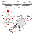
도 1은 폴더블 영상표시장치의 접힘 상태 개념도들 이고,
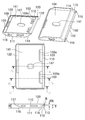
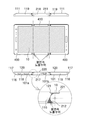
도 2는 진동판 영역을 갖는 플렉시블 디스플레이가 적용되고 삼각기둥 가변 공간 형성이 가능한 몸체가 적용된 폴더블 영상표시장치의 접힘 상태 사시도, 접힘 상태 정면도 및 펼침 상태 정면도 이며,
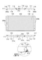
도 3은 진동판 영역을 갖는 플렉시블 디스플레이가 적용되고 삼각기둥 가변 공간 형성이 가능하며 슬라이딩 개방구가 일면에 형성되어있는 몸체가 적용된 폴더블 영상표시장치의 접힘 상태 사시도, 접힘 상태 정면도 및 펼침 상태 정면도 이고,
도 4는 도 2의 다른 실시예 이며,
도 5는 도 4의 다른 실시예 이고,
도 6은 도 2 및 도 4의 플렉시블 디스플레이에 진동판 영역이 적용된 상태를 보여주는 개념도 및 플렉시블 디스플레이의 표시를 생략하여 진동 발생기 적용을 보여주는 개념도 이며,
도 7은 도 6의 Section Cut AA-AA, Section Cut AB-AB, Section Cut AC-AC 및 Section Cut AD-AD에 대한 단면도 이고,
도 8은 도 3 및 도 5의 플렉시블 디스플레이에 진동판 영역이 적용된 상태를 보여주는 개념도 및 플렉시블 디스플레이의 표시를 생략하여 진동 발생기 적용을 보여주는 개념도 이며,
도 9는 도 8의 Section Cut AE-AE, Section Cut AF-AF, Section Cut AG-AG 및 Section Cut AH-AH에 대한 단면도 이고,
도 10은 도 5의 폴더블 영상표시장치를 이용한 입체 소리발생 예를 보여주는 개념도 이며,
도 11은 도 2의 실시예에 대한 분해 사시도 이고,
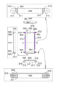
도 12는 도 2의 실시예를 위한 제1몸체 및 제3몸체의 사시도, 평면도 및 정면도 이며,
도 13은 도 12의 Section Cut A-A, Section Cut B-B 및 Section Cut C-C에 대한 단면도 이고,
도 14는 도 2의 실시예를 위한 제2몸체의 사시도, 평면도 및 정면도 이며,
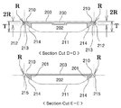
도 15는 도 14의 Section Cut D-D 및 Section Cut E-E에 대한 단면도 이고,
도 16은 도 2의 실시예를 위한 미끄럼 이동판의 사시도, 평면도 및 단면도 이며,
도 17은 도 2의 실시예를 위한 고정판의 평면도 및 단면도 이고,
도 18은 도 2의 실시예를 위한 탄성부재의 적용 개념도 이며,
도 19는 도 2의 평면 펼침 상태에 대한 평면도, 정면도 및 부분 상세도 이고,
도 20은 도 19의 평면 펼침 상태에서 10도 초과 펼쳐짐이 수행된 상태에 대한 평면도, 정면도 및 부분 상세도 이며,
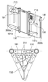
도 21은 도 2의 접힘 상태에서 제3몸체가 노트북 모드로 초과 펼쳐짐이 수행된 상태에 대한 사시도 및 평면도 이고,
도 22는 도 21의 Section Cut F-F에 대한 단면도 및 부분 상세도들 이며,
도 23은 도 2의 접힘 상태에서 제1몸체는 평면 펼침되고 제3몸체는 노트북 모드로 초과 펼쳐짐이 수행된 상태에 대한 사시도 및 부분 상세도들 이고,
도 24는 도 2의 평면 펼침 상태에 대한 플렉시블 디스플레이의 비접착 부위 개념도 및 상시 밀착부위 개념도 이며,
도 25는 도 24와 달리 플렉시블 디스플레이의 진동판 영역이 타원 형상을 갖는 예시도 이고,
도 26은 도 3의 실시예에 대한 분해 사시도 이며,
도 27은 도 3의 실시예를 위한 제1몸체와 제3몸체의 사시도 이고,
도 28은 도 3의 실시예를 위한 제1몸체와 제3몸체의 평면도, 정면도, 측면도 및 단면도들 이며,
도 29는 도 3의 실시예를 위한 제2몸체의 평면도, 정면도, 측면도 및 단면도들 이고,
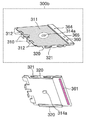
도 30은 도 3의 실시예를 위한 제1몸체 적용 미끄럼 이동판(300a)의 사시도 및 부분 상세도 이며,
도 31은 도 30의 평면도 및 단면도 이고,
도 32는 도 3의 실시예를 위한 제3몸체 적용 미끄럼 이동판(300b)의 사시도 및 부분 상세도 이며,
도 33은 도 3의 평면 펼침 상태에 대한 후면도, 평면도 및 정면도 이고,
도 34는 도 33의 Section Cut G-G 및 Section Cut H-H에 대한 단면도 및 부분 상세도 이며,
도 35는 도 33의 Section Cut I-I 및 Section Cut J-J에 대한 단면도 및 부분 상세도 이고,
도 36은 도 33의 Section Cut K-K에 대한 및 부분 상세도 이며,
도 37은 도 3의 접힘 상태에서 제1몸체는 접힘 유지되고 제3몸체는 노트북 모드로 초과 펼쳐짐이 수행된 상태에 대한 사시도 및 평면도 이고,
도 38은 도 37의 Section Cut L-L 및 Section Cut M-M에 대한 단면도 및 부분 상세도 이며,
도 39는 도 37의 Section Cut N-N에 대한 단면도 이고,
도 40은 도 3의 평면 펼침 상태에 대한 플렉시블 디스플레이의 비접착 부위 개념도 및 상시 밀착부위 개념도 이며,
도 41은 도 4의 실시예에 대한 분해 사시도 이고,
도 42는 도 4의 실시예를 위한 제1몸체 및 제3몸체의 평면도, 정면도. 후면도 및 단면도 이며,
도 43은 도 4의 실시예를 위한 제2몸체의 평면도, 정면도. 후면도 및 단면도 이고,
도 44는 도 4의 평면 펼침 상태에 대한 평면도, 정면도 및 부분 상세도 이며,
도 45는 도 4의 평면 펼침 상태에 대한 화면 표시면 반대측의 사시도 및 평면도 이고,
도 46은 도 4의 평면 펼침 상태에서 제3몸체는 펼침 유지되고 제1몸체는 노트북 모드로 초과 펼쳐짐이 수행된 상태에 대한 평면도 및 정면도 이며,
도 47은 도 46의 Section Cut O-O에 대한 단면도 및 부분 상세도들 이고,
도 48은 도 4의 접힘 상태에 대한 평면도 및 제2몸체 측 에서의 정면도 이며,
도 49는 도 48의 Section Cut P-P에 대한 단면도 및 부분 상세도들 이고,
도 50은 제1몸체와 제3몸체에 경사면1과 그립면1의 적용 유무에 따른 차이와 함께 접힘 각도에 따른 차이를 보여주는 도 4의 접힘 상태에 대한 평면도들 이며,
도 51은 도 5의 실시예에 대한 분해 사시도 이고,
도 52는 도 5의 실시예를 위한 제1몸체 및 제3몸체의 평면도, 정면도. 후면도 및 단면도 이며,
도 53은 도 52의 Section Cut Q-Q, Section Cut R-R, Section Cut S-S 및 Section Cut T-T에 대한 단면도 이고,
도 54는 도 5의 실시예를 위한 제2몸체의 평면도, 정면도. 후면도 및 단면도 이며,
도 55는 도 5의 평면 펼침 상태에 대한 평면도, 정면도 및 부분 상세도 이고,
도 56은 도 5의 평면 펼침 상태에서 제1몸체는 펼침 유지되고 제3몸체는 노트북 모드로 초과 펼쳐짐이 수행된 상태에 대한 평면도 및 정면도 이며,
도 57은 도 56의 Section Cut U-U에 대한 단면도 및 부분 상세도들 이고,
도 58은 도 5의 접힘 상태에 대한 평면도 및 제2몸체 측 에서의 정면도 이며,
도 59는 도 58의 Section Cut V-V에 대한 단면도 및 부분 상세도들 이고,
도 60은 도 5의 평면 펼침 상태에 대한 플렉시블 디스플레이의 비접착 부위 개념도 및 상시 밀착부위 개념도 이며,
도 61은 도 4의 실시예에 힌지 범퍼가 적용된 개념도들 이고,
도 62는 도 5의 실시예에 힌지 범퍼가 적용된 개념도들 이며,
도 63은 도 3의 실시예에 힌지 범퍼가 적용된 접힘 상태에서 낙하되어도 힌지 범퍼에 의해 1차 충격 흡수가 가능함을 보여주는 개념도 이고,
도 64는 도 63의 접힘 상태가 펼침 상태로 전환되어 낙하되어도 힌지 범퍼에 의해 2차 충격 흡수가 가능함을 보여주는 개념도 이며,
도 65는 도 5의 실시예에 회전 걸림판이 적용되어 제1몸체 또는 제3몸체에 대한 접힘 상태와 완전 평면 펼침 상태에 대한 선택적 걸림을 보여주는 개념도 이고,
도 66은 도 5의 실시예에 회전 걸림판이 적용되어 제1몸체 또는 제3몸체에 대한 초과 펼침 상태에 대한 선택적 걸림을 보여주는 개념도 이며,
도 67은 도 4 및 도 5의 실시예의 제2몸체에 탈부착 베터리가 적용됨을 보여주는 개념도 이고,
도 68은 슬라이딩 개방구가 그립면1에 형성된 도 3 및 도 5의 실시예가 도 2 및 도 4의 실시예 보다 넓은 표시화면을 제공할 수 있음을 보여주는 개념도 이며,
도 69는 도 2 부터 도 5의 실시예가 다양한 상태로 활용될 수 있음을 보여주는 개념도 이고,
도 70은 도 2 부터 도 5의 실시예의 가변 공간에 무선이어폰 및 터치펜이 적용될 수 있음을 보여주는 사시도 및 평면도 이며,
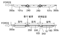
도 71은 도 3 및 도 5의 실시예에 적용된 가변 공간 및 미끄럼 이동판(300a, 300b)이 방열 기능을 수행함을 보여주는 개념도 이고,
도 72는 도 3 및 도 5의 실시예에 적용된 미끄럼 이동판에 손바닥을 이용해 외력을 작용하면 플렉시블 디스플레이의 미접착 부위가 융기되어 솟아 올라옴을 보여주는 개념도 이며,
도 73은 도 3 및 도 5 실시예의 완전 평면 펼침 상태에서 제1몸체 또는 제3몸체의 어느 한쪽에 회전력을 가하면 힌지 축 회전 감지 센서가 회전 량을 감지할 수 있음을 보여주는 개념도 이고,
도 74는 초과 펼침 회전시 고정되지 않은 플렉시블 디스플레이의 끝단이 힌지 영역 겹침으로 인해 밀림 이동이 발생함을 보여주는 개념도이다.1 is a conceptual diagram of a folded state of the foldable image display device,
2 is a folded state perspective view, a folded state front view, and a folded state front view of a foldable image display device to which a flexible display having a diaphragm area is applied and a body capable of forming a triangular prism variable space is applied,
3 is a folded display perspective view, a folded state front view and a folded state front view of a foldable image display device to which a flexible display having a diaphragm area is applied, a triangular prism variable space can be formed, and a body having a sliding opening formed on one surface is applied. Is also
Figure 4 is another embodiment of Figure 2,
Figure 5 is another embodiment of Figure 4,
6 is a conceptual view showing a state in which the diaphragm area is applied to the flexible display of FIGS. 2 and 4 and a conceptual view showing the application of a vibration generator by omitting the display of the flexible display,
7 is a cross-sectional view of Section Cut AA-AA, Section Cut AB-AB, Section Cut AC-AC and Section Cut AD-AD of FIG. 6,
8 is a conceptual view showing a state in which the diaphragm area is applied to the flexible displays of FIGS. 3 and 5 and a conceptual view showing the application of a vibration generator by omitting the display of the flexible display,
9 is a cross-sectional view of Section Cut AE-AE, Section Cut AF-AF, Section Cut AG-AG and Section Cut AH-AH of FIG. 8,
10 is a conceptual view showing an example of stereoscopic sound generation using the foldable image display device of FIG. 5,
11 is an exploded perspective view of the embodiment of FIG. 2,
12 is a perspective view, a plan view, and a front view of the first body and the third body for the embodiment of FIG. 2,
13 is a cross-sectional view of Section Cut AA, Section Cut BB and Section Cut CC of FIG. 12,
14 is a perspective view, a plan view, and a front view of a second body for the embodiment of FIG. 2,
15 is a cross-sectional view of Section Cut DD and Section Cut EE of FIG. 14,
16 is a perspective view, a plan view, and a sectional view of a sliding plate for the embodiment of FIG. 2,
17 is a plan view and a cross-sectional view of the fixing plate for the embodiment of FIG. 2,
18 is a conceptual diagram of the application of the elastic member for the embodiment of FIG. 2,
19 is a plan view, a front view, and a partial detail view of the flat unfolded state of FIG. 2;
20 is a plan view, a front view, and a partial detail view of a state in which a spread of more than 10 degrees is performed in the flat unfolded state of FIG. 19;
21 is a perspective view and a plan view of a state in which the third body is over-folded in the notebook mode in the folded state of FIG. 2,
22 is a cross-sectional view and partial detailed views of Section Cut FF of FIG. 21,
23 is a perspective view and partial detailed views of a state in which the first body is flat unfolded and the third body is over-expanded in a laptop mode in the folded state of FIG. 2,
FIG. 24 is a conceptual view of a non-adhesive part of a flexible display and a conceptual view of an always-closed part of the flat unfolded state of FIG. 2;
25 is an exemplary view in which the diaphragm region of the flexible display has an elliptical shape, unlike FIG. 24,
26 is an exploded perspective view of the embodiment of FIG. 3,
27 is a perspective view of a first body and a third body for the embodiment of FIG. 3,
28 is a plan view, front view, side view and cross-sectional views of the first body and the third body for the embodiment of FIG. 3,
29 is a plan view, a front view, a side view, and cross-sectional views of a second body for the embodiment of FIG. 3,
30 is a perspective view and a partial detail view of a first body-applied sliding
31 is a plan view and a cross-sectional view of FIG. 30,
32 is a perspective view and a partial detailed view of a third body-applied sliding
33 is a rear view, a plan view, and a front view of the flat unfolded state of FIG. 3;
34 is a cross-sectional view and a partial detailed view of Section Cut GG and Section Cut HH of FIG. 33,
35 is a cross-sectional view and a partial detailed view of Section Cut II and Section Cut JJ of FIG. 33,
36 is a partial cut view and a section cut KK of FIG. 33;
37 is a perspective view and a plan view of a state in which the first body is kept folded and the third body is over-folded in a laptop mode in the folded state of FIG. 3,
38 is a cross-sectional view and a partial detail view of Section Cut LL and Section Cut MM of FIG. 37,
39 is a cross-sectional view of Section Cut NN of FIG. 37,
FIG. 40 is a conceptual view of a non-adhesive part of a flexible display and a conceptual view of an always-closed part of the flat unfolded state of FIG. 3;
41 is an exploded perspective view of the embodiment of FIG. 4,
42 is a plan view and a front view of the first body and the third body for the embodiment of FIG. 4. Rear view and sectional view,
43 is a plan view and a front view of a second body for the embodiment of FIG. 4; Rear view and cross section,
44 is a plan view, a front view, and a partial detail view of the flat unfolded state of FIG. 4;
45 is a perspective view and a plan view of the opposite side of the screen display surface for the flattened state of FIG. 4;
46 is a plan view and a front view of a state in which the third body is maintained unfolded and the first body is over-expanded in a notebook mode in the flat unfolded state of FIG. 4;
47 is a cross-sectional view and partial detailed views of Section Cut OO of FIG. 46,
48 is a plan view of the folded state of FIG. 4 and a front view from the second body side,
49 is a cross-sectional view and partial detailed views of Section Cut PP of FIG. 48,
50 is a plan view of the folded state of FIG. 4 showing the difference depending on the folding angle together with the difference between the application of the
51 is an exploded perspective view of the embodiment of FIG. 5,
52 is a plan view and a front view of the first body and the third body for the embodiment of FIG. 5. Rear view and sectional view,
53 is a cross-sectional view of Section Cut QQ, Section Cut RR, Section Cut SS and Section Cut TT of FIG. 52,
54 is a plan view and a front view of a second body for the embodiment of FIG. 5; Rear view and sectional view,
55 is a plan view, a front view, and a partial detail view of the flat unfolded state of FIG. 5;
56 is a plan view and a front view of a state in which the first body is maintained unfolded and the third body is over-expanded in a notebook mode in the flat unfolded state of FIG. 5,
57 is a cross-sectional view and partial detailed views of the section cut UU of FIG. 56,
58 is a plan view of the folded state of FIG. 5 and a front view from the second body side,
59 is a cross-sectional view and partial detailed views of Section Cut VV of FIG. 58;
FIG. 60 is a conceptual view of a non-adhesive part of a flexible display for a flat unfolded state of FIG. 5 and a conceptual view of an always-contact part;
61 are conceptual diagrams to which the hinge bumper is applied to the embodiment of FIG. 4;
FIG. 62 are conceptual diagrams to which the hinge bumper is applied to the embodiment of FIG. 5;
63 is a conceptual diagram showing that primary shock absorption is possible by the hinge bumper even when the hinge bumper is dropped in the folded state to which the embodiment of FIG. 3 is applied;
FIG. 64 is a conceptual diagram showing that secondary shock absorption is possible by the hinge bumper even when the folded state of FIG. 63 is switched to the unfolded state and dropped.
FIG. 65 is a conceptual view showing a rotational locking plate is applied to the embodiment of FIG. 5 and showing a selective engagement with respect to a folded state and a fully flattened state with respect to a first body or a third body,
FIG. 66 is a conceptual view showing a selective jamming of an excess unfolded state with respect to a first body or a third body by applying a rotation locking plate to the embodiment of FIG. 5;
67 is a conceptual diagram showing that the detachable battery is applied to the second body of the embodiment of FIGS. 4 and 5,
68 is a conceptual view showing that the embodiment of FIGS. 3 and 5 in which the sliding opening is formed on the
69 is a conceptual diagram showing that the embodiments of FIGS. 2 to 5 can be utilized in various states;
70 is a perspective view and a plan view showing that a wireless earphone and a touch pen can be applied to the variable spaces of the embodiment of FIGS. 2 to 5,
71 is a conceptual diagram showing that the variable space and the sliding moving
FIG. 72 is a conceptual diagram showing that an unadhesive portion of a flexible display rises and rises when an external force is applied using a palm to the sliding plate applied to the embodiments of FIGS. 3 and 5,
73 is a conceptual diagram showing that the hinge axis rotation detection sensor can detect the amount of rotation when a rotational force is applied to either the first body or the third body in the fully flattened state of the FIGS. 3 and 5 embodiment,
74 is a conceptual diagram showing that the edge of the flexible display that is not fixed when the over-unfolding is rotated causes a sliding movement due to overlapping of the hinge region.
이하 첨부된 도면들을 참조하여 본 발명의 실시 예들을 상세하게 설명하기로 한다. Hereinafter, exemplary embodiments of the present invention will be described in detail with reference to the accompanying drawings.
본 명세서에서 사용된 용어는 실시 예들을 설명하기 위한 것이며 본 발명을 제한하고자 하는 것은 아니다. 본 명세서에서, 단수형은 문구에서 특별히 언급하지 않는 한 복수형도 포함한다. 또한, 설명의 순서에 따라 제시되는 참조 부호는 그 순서에 반드시 한정되지 않는다.The terminology used herein is for describing the embodiments and is not intended to limit the present invention. In this specification, the singular form also includes the plural form unless otherwise specified in the phrase. In addition, reference numerals presented in the order of description are not necessarily limited to the order.
판상 고정형의 스마트폰을 대체할 수 있는 영상표시장치로서 플렉시블 디스플레이가 적용된 다양한 폴더블 영상표시장치가 제시되고 있으며 이러한 폴더블 영상표시장치는 접히는 부위에서의 힌지 적용 유무에 따라 무 힌지 방식과 힌지 적용 방식으로 구분되고 다수의 특허(대한민국 특허 10-0125125, 10-0017875, 10-0106358, 10-0129704, 10-0017606)가 제시되었다.As a video display device that can replace a plate-type fixed smartphone, various foldable video display devices with flexible displays have been proposed, and these foldable video display devices are hinged and hinged depending on whether or not hinges are applied at the folding part. Separated in a number of ways (Korea Patent 10-0125125, 10-0017875, 10-0106358, 10-0129704, 10-0017606) has been proposed.
상기의 제시된 특허들 중 본 발명인에 의해 제시된 대한민국 특허 10-0106358 외에는 접힘 방식만 다르고 판상의 영상표시장치를 판상으로 접어 휴대가 간편하며 다시 판상으로 펼쳐져 대화면을 제공하는 단순 물리적인 기능만 동일하게 제시되고 있다.Among the patents presented above, except for the Republic of Korea Patent 10-0106358 proposed by the present inventors, only the folding method is different, the image display device on the plate is folded to the plate for easy portability, and it is unfolded again on the plate, and only the simple physical function of providing a large screen is presented identically. Is becoming.
본 발명인에 의해 기 제시된 대한민국 특허 10-0106358에는 삼각기둥 접힘 상태를 가능케하는 실시예가 포함되어있으나 이하 제시되는 본 발명의 실시예의 제1몸체 및 제3몸체에 해당하는 덮개판(발명인에 의해 이하 제시될 제1몸체 및 제3몸체는 힌지 직경이 제1몸체 및 제3몸체 두께보다 작거나 같은 반면 기존 특허의 덮개판의 힌지 직경은 박판 형상인 덮개판의 두께보다 몇배 이상 크다)과 제2몸체에 해당하는 고정몸체(제2몸체의 힌지 직경과 같거나 조금 두꺼운 판상형의 몸체에 비해 기존 특허의 고정몸체는 삼각기둥 형상을 이루고 있다)의 외부면 윤곽 형상이 완전히 다르고, 덮개판에 내부공간이 반영되지 않아 제어부의 구성품들을 적용할 수 없어 고정몸체에 일괄 적용하며, 삼각기둥 접힘 상태시 내측에 중공형의 가변 공간이 형성되지 않음이 다르다.The Republic of Korea Patent No. 10-0106358 previously presented by the present inventor includes an example that enables a triangular prism folding state, but a cover plate corresponding to the first body and the third body of the embodiment of the present invention (hereinafter presented by the inventor) The first body and the third body to be hinged have a hinge diameter smaller than or equal to the thickness of the first body and the third body, while the hinge diameter of the cover plate of the existing patent is several times larger than the thickness of the thin plate-shaped cover plate) and the second body. The shape of the outer surface of the fixed body (corresponding to the hinge body of the second body or a slightly thicker plate-like body than that of the existing patent has a triangular prism shape) is completely different, and the inner space on the cover plate is completely different. As it is not reflected, the components of the control unit cannot be applied, so it is applied collectively to the fixed body. Garda.
현재 스마트폰을 사용하는 사용자들은 대화면이며 높은 휴대 편의성, 충분한 베터리 용량을 갖으며 가볍고 얇은 두께와 같은 서로 상충되는 요구조건을 충족하기를 원하며 또한 무선 또는 유선 이어폰, 보조 베터리, 무선 충전기, 네비게이션, 블랙박스, AI 스피커 및 액션카메라와 같은 보조 장치들 중에서 하나 이상을 스마트폰과 같이 사용하고 있는 실정이다. Currently, smartphone users want to meet conflicting requirements such as large screen, high portability, sufficient battery capacity, light weight and thin thickness, and also include wireless or wired earphones, auxiliary batteries, wireless chargers, navigation, Currently, one or more of auxiliary devices such as black boxes, AI speakers, and action cameras are used together with a smartphone.
이들 보조 장치들 중에서 음성인식 및 음성 대답 기능이 강점인 AI 스피커의 중요도는 점점 커지고 있으며 자동차, 사무실 및 가정 영역에서도 적용이 확대되고 있다.Among these auxiliary devices, the importance of the AI speaker, which has strong voice recognition and voice answering functions, is increasing in importance, and its application is also expanding in the automobile, office, and home areas.
반면 사용자들이 하루 중 대부분의 시간동안 들고 다니며 정보검색, 통화 및 문자전송, 이메일 및 카메라 촬영에 주로 사용되는 스마트폰 들 중 고가의 스마트폰에는 음성인식 기능과 카메라 촬영 기능에 AI가 적용되고 있으나 판상형 구조로 인해 AI 스피커에 비해 고 사양 임에도 불구하고 AI 스피커를 대체하지 못하고 있다.On the other hand, among the smartphones that users carry for most of the day and are mainly used for information retrieval, call and text transmission, e-mail and camera shooting, AI is applied to voice recognition and camera shooting functions on expensive smartphones, but it is plate-shaped Due to its structure, it is not a substitute for AI speakers despite its high specification compared to AI speakers.
따라서 본 발명인은 플렉시블 디스플레이를 이용해 접힘 및 펼침 상태와 무관하게 화면 표시면의 전(Front)방향에 대한 화면 표시 및 소리 발생을 동시에 구현하며 판상 형태의 2차원 적인 단순 접힘이 아닌 몸체의 접힘시 형성되는 3차원 적인 가변 공간에 스피커를 적용해 저음 발생을 증대시켜 폴더블 기기의 휴대 특성과 AI 스피커 기능 및 영상표시장치 기능을 모두 갖는 폴더블 영상표시장치를 이하 제시한다.Therefore, the present inventor uses a flexible display to simultaneously realize the screen display and sound generation in the front direction of the screen display regardless of the folded and unfolded state, and is formed when the body is folded, not a two-dimensional simple folding in the form of a plate. A foldable video display device having both portable characteristics of a foldable device, AI speaker function, and video display device function is proposed below by applying a speaker to a 3D variable space.
도 1은 폴더블 영상표시장치의 접힘 상태 개념도들 이다.1 is a conceptual diagram of a folded state of the foldable image display device.
도 1에 나타내어진 바와 같이 플렉시블 디스플레이(10)가 적용된 폴더블 영상표시장치를 이용해 접힘 상태시 가변 공간이 형성되고 펼침시 가변 공간이 사라지는 형태가 가능한 경우는 단순 판상형태의 2분할 2차원 접힘이 아니라 원기둥 또는 각기둥을 형성하는 3차원 접힘이어야 한다.As shown in FIG. 1, when a foldable image display device to which the
단순 판상형태의 2분할 2차원 접힘의 경우에는 지면을 이용한 경우에만 제한적인 삼각기둥 접힘이 가능한 단점이 존재한다.In the case of a simple plate-shaped two-part two-dimensional folding, there is a disadvantage that a limited triangular prism can be folded only when the ground is used.
3차원 접힘중 원기둥 접힘은 플렉시블 디스플레이 외에도 몸체, 제어부 및 베터리를 포함한 모든 구성품들이 플렉시블 가능해야 구현이 가능하며 접힘시 원기둥 유지 및 펼침시 평면 유지가 어려운 문제가 존재한다.Among the three-dimensional folding, the folding of the cylinder can be implemented only when all components including the body, the control unit, and the battery are flexible, in addition to the flexible display, and there is a problem of maintaining the cylinder during folding and maintaining the plane when unfolding.
4각기둥 이상의 각기둥 접힘은 플렉시블 디스플레이와 연결 기판을 포함한 일부 구성품만이 플렉시블하면 구현이 가능한 장점을 갖으나 몸체가 네부분 이상으로 나뉘어 제어부 및 베터리 적용을 위한 유효 공간 확보가 어렵고 접힘 및 펼침 통제가 어려운 문제가 존재한다.Folding of a prism over 4 prism has the advantage that it can be realized if only some components, including a flexible display and a connecting board, are flexible, but the body is divided into four or more parts, making it difficult to secure effective space for control and battery application and difficult to control folding and unfolding. The problem exists.
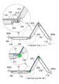
그러나 삼각기둥 접힘은 플렉시블 디스플레이와 연결 기판을 포함한 일부 구성품만이 플렉시블하면 구현이 가능한 장점을 갖으며 몸체가 세부분으로 나뉘어 제어부 및 베터리 적용을 위한 공간 확보가 용이하고 접힘 및 펼침 통제가 어렵지 않음과 더불어 2분할 2차원 접힘의 경우와 달리 접힘 상태시 삼각기둥 자체의 고유특성인 구조적 안정성을 이룰 수 있는 장점도 갖는다.However, the triangular prism has the advantage that can be realized if only some components, including the flexible display and the connecting board, are flexible, and the body is divided into subdivisions, so it is easy to secure space for control and battery application, and it is not difficult to control folding and unfolding. In addition, unlike the case of two-part two-dimensional folding, it has the advantage of being able to achieve structural stability, which is a unique characteristic of the triangular column itself when folded.
또한 삼각기둥 형성시 어떠한 상태로 배치하여도 방향을 달리하는 두면 이상이 노출 상태로 유지되는 장점도 갖으며 삼각기둥 형상의 가변 공간에 스피커를 적용할 경우에는 가변 공간을 공명통(Resonance Chamber)으로 활용해 저음 특성을 보강할 수 있는 부가적인 장점도 얻을 수 있다.In addition, when forming a triangular prism, it has the advantage that two or more sides with different orientations are maintained in an exposed state, and when a speaker is applied to a triangular column-shaped variable space, the variable space is used as a resonance chamber. It also has the added advantage of enhancing bass characteristics.
이는 플렉시블 디스플레이를 소리 발생 수단으로 이용하는 경우에 갖게되는 저음 발생의 불리함을 해결할 수 있는 하나의 대안이 될 수 있다.This may be an alternative solution to the disadvantages of bass generation when using a flexible display as a sound generating means.
본 발명인은 이러한 삼각기둥 형상의 가변 공간 특징들을 구현할 수 있는 몸체와 접힘 및 펼침이 자유롭고 화면 표시면의 일부를 진동판 영역으로 이용해 화면 표시면의 전(Front)방향으로 화면 표시와 함께 소리를 발생 시킬 수 있도록 함과 더불어 두방향 이상에서의 카메라 감시 및 음성 명령 입력이 가능한 폴더블 영상표치장치의 실시예를 이하 도면들을 이용해 제시한다. The present inventor can freely fold and unfold the body capable of realizing the variable spatial features of the triangular prism shape, and use a part of the screen display surface as a diaphragm area to generate sound together with the screen display in the front direction of the screen display surface. In addition, an embodiment of a foldable image display device capable of monitoring a camera in two directions or more and inputting a voice command is provided using the drawings.
도 2는 진동판 영역을 갖는 플렉시블 디스플레이가 적용되고 삼각기둥 가변 공간 형성이 가능한 몸체가 적용된 폴더블 영상표시장치의 접힘 상태 사시도, 접힘 상태 정면도 및 펼침 상태 정면도 이며, 도 3은 진동판 영역을 갖는 플렉시블 디스플레이가 적용되고 삼각기둥 가변 공간 형성이 가능하며 슬라이딩 개방구가 일면에 형성되어있는 몸체가 적용된 폴더블 영상표시장치의 접힘 상태 사시도, 접힘 상태 정면도 및 펼침 상태 정면도 이고, 도 4는 도 2의 다른 실시예 이며, 도 5는 도 4의 다른 실시예 이고, 도 6은 도 2 및 도 4의 플렉시블 디스플레이에 진동판 영역이 적용된 상태를 보여주는 개념도 및 플렉시블 디스플레이의 표시를 생략하여 진동 발생기 적용을 보여주는 개념도 이며, 도 7은 도 6의 Section Cut AA-AA, Section Cut AB-AB, Section Cut AC-AC 및 Section Cut AD-AD에 대한 단면도 이고, 도 8은 도 3 및 도 5의 플렉시블 디스플레이에 진동판 영역이 적용된 상태를 보여주는 개념도 및 플렉시블 디스플레이의 표시를 생략하여 진동 발생기 적용을 보여주는 개념도 이며, 도 9는 도 8의 Section Cut AE-AE, Section Cut AF-AF, Section Cut AG-AG 및 Section Cut AH-AH에 대한 단면도 이다.2 is a folded state perspective view, a folded state front view, and an unfolded state front view of a foldable image display device to which a flexible display having a diaphragm area is applied and a body capable of forming a triangular prism variable space is applied, and FIG. 3 has a diaphragm area A flexible display is applied, a triangular prism variable space can be formed, and a folded state perspective view, a folded state front view, and an unfolded state front view of a foldable image display device with a body having a sliding opening formed on one surface, and FIG. 2 is another embodiment, FIG. 5 is another embodiment of FIG. 4, and FIG. 6 is a conceptual diagram showing a state in which the diaphragm region is applied to the flexible displays of FIGS. 2 and 4 and omitting the display of the flexible display to apply a vibration generator. It is a conceptual diagram showing, and FIG. 7 is a section cut AA-AA, a section cut AB-AB, a section cut AC-AC and a section of FIG. Cut AD-AD is a cross-sectional view, FIG. 8 is a conceptual view showing a state in which the diaphragm area is applied to the flexible display of FIGS. 3 and 5 and a conceptual view showing the application of a vibration generator by omitting the display of the flexible display, and FIG. Section Cut AE-AE, Section Cut AF-AF, Section Cut AG-AG and Section Cut AH-AH.
도 2부터 도 9에 나타내어진 바와 같이 본 발명의 폴더블 영상표시장치(1)는 제어부(20), 접힘 및 펼침이 가능하며 접힘 상태시 평면을 형성하는 화면 표시면 반대 면의 접착면 일부분이 소리 발생을 위한 비접착 영역인 진동판 영역(11)을 갖는 플렉시블 디스플레이(10) 및 플렉시블 디스플레이(10)가 고정 또는 지지되고 접힘 및 펼침이 가능한 몸체(100)를 포함하여 구성된다.2 to 9, the foldable
도 2부터 도 5에 나타내어진 본 발명의 실시 예들과 같이 몸체(100)는 제어부(20) 및 베터리의 적용을 위한 내부공간을 갖으며 접힘시 형성되고 펼침시 사라지는 가변 공간(700)을 형성하는 특징을 갖는다.2 to 5, as shown in the embodiments of the present invention, the
도 6부터 도 9에 나타내어진 바와 같이 진동판 영역(11)은 원형 또는 타원형의 비접착 영역을 이루며 제어부에 연결되어 구동되는 진동 발생기(30)에 의해 진동되고 화면 표시면의 전 방향(Front) 측으로 소리를 발생시키는 특징을 갖는다.6 to 9, the
도 2부터 도 5에 나타내어진 바와 같이 화면 표시면 반대 측 몸체의 일면에는 가변 공간 측을 향하며 스피커(171)가 적용되며 삼각기둥 형상의 내부 가변 공간(700)을 공명통(Resonance Chamber)으로 활용해 저음 특성을 보강할 수 있다.2 to 5, the
폴더블 영상표시장치에 있어서 가변 공간(700)은 도 1에 나타내어진 바와 같이 원기둥, 삼각기둥, 사각기둥, 오각기둥 또는 육각기둥 중 어느 하나의 형상을 이루며 접힘이 이루어지는 접힘 축의 양측 끝단 부분은 개방 형성되어있는 특징을 갖는다.In the foldable image display device, the
도 2부터 도 5에 나타내어진 바와 같이 본 발명의 실시 예들은 삼각기둥 형상의 가변 공간(700)이 형성되는 몸체(100)가 적용된다.2 to 5, in the embodiments of the present invention, a
도 2부터 도 5에 나타내어진 바와 같이 몸체(100)는 플렉시블 디스플레이(10)의 일측 끝단이 고정 또는 지지되며 모서리 부분에 힌지 관련 형상이 적용되어있는 제1몸체(101a)와 제3몸체(101c) 및 플렉시블 디스플레이(10)의 중간 부분이 고정 또는 지지되며 일측 모서리가 제1몸체(101a)에 힌지 결합되고 반대편 일측 모서리는 제3몸체(101c)에 힌지 결합되는 제2몸체(101b)를 포함하여 구성된다.2 to 5, the
도 2부터 도 9에 나타내어진 바와 같이 제1몸체(101a) 및 제3몸체(101c)에는 플렉시블 디스플레이(10)의 일측 끝단 화면 표시면 반대 측 면이 접착 고정되는 디스플레이 접착면1(311)이 일면에 반영되어 있고 힌지 축과 수직인 방향으로 미끄럼 이동 가능한 상태로 조립되는 미끄럼 이동판(300 또는 300a, 300b)이 적용된다.2 to 9, the
도 6부터 도 9 및 후술할 도 11, 도 16, 도 30, 도 32, 도 41 및 도 51에 나타내어진 바와 같이 미끄럼 이동판(300)의 디스플레이 접착면1(311)에는 진동 발생기(30)의 고정을 위한 진동 발생기 적용구1(314)이 관통 또는 함몰 형성되어 있고 미끄럼 이동판(300a, 300b)의 디스플레이 접착면1(311)에는 진동 발생기(30)의 고정을 위한 진동 발생기 적용구1(314a)가 관통 또는 함몰 형성되어 있다.As shown in FIGS. 6 to 9 and FIGS. 11, 16, 30, 32, 41, and 51 to be described later, the
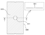
도 6부터 도 9 및 후술할 도면11, 도 17, 도 26, 도 41 및 도 51에 나타내어진 바와 같이 제2몸체(101b)에는 플렉시블 디스플레이(10)의 중간부분 화면 표시면 반대 측 면이 접착 고정되는 면인 디스플레이 접착면2(510)가 일면에 반영되어있고 반대편 일면은 제2몸체(101b)의 일면에 접착 고정 또는 조립되는 고정판(500)이 적용되고 디스플레이 접착면2(510)에는 진동 발생기(30)의 고정을 위한 진동 발생기 적용구2(511 또는 511a)가 관통 또는 함몰 형성되어 있다.As shown in FIGS. 6 to 9 and FIGS. 11, 17, 26, 41, and 51 to be described later, the opposite side of the display surface of the middle portion of the
후술할 도 11, 도 12 및 도 42에 나타내어진 바와 같이 제1몸체(101a) 및 제3몸체(101c)에는 미끄럼 이동판(300)의 미끄럼 이동 및 지지를 위해 화면 표시면의 반대면 측 일면으로부터 미끄럼 이동판(300)의 두께 깊이로 함몰 형성된 미끄럼 이동판 지지면1(141)이 형성되어 있고 미끄럼 이동판 지지면1(141)에는 접힘 및 펼침 수행시 미끄럼 이동판 지지면(141) 측으로 돌출된 진동 발생기(30) 또는 진동 발생기 적용구1(314)와 미끄럼 이동판 지지면1(141) 사이의 간섭 방지를 위해 진동 발생기 지지 장공(147)이 형성되어있다.11, 12, and 42 to be described later, the
후술할 도 11, 도 14, 도 41 및 도 43에 나타내어진 바와 같이 제2몸체(101b)에는 화면 표시면의 반대면 측 일면으로부터 고정판(500)의 두께 깊이로 함몰 형성된 고정판 접착면(203)이 형성되어 있고, 고정판 접착면(203)에는 고정판 접착면(203) 측으로 돌출된 진동 발생기(30) 또는 진동 발생기 적용구2(511)와의 간섭 방지를 위해 진동 발생기 고정구(230)가 형성되어 있다.11, 14, 41, and 43, the
도 7의 Section Cut AA-AA에 나타내어진 바와 같이 제1몸체(101a) 및 제3몸체(101c)의 진동 발생기 지지 장공(147)에는 접힘 및 펼침시 진동 발생기 지지 장공(147) 측으로 돌출된 진동 발생기(30) 또는 진동 발생기 적용구1(314)과 진동 발생기 지지 장공(147) 내부 둘레면 사이의 간섭 방지를 위해 돌출된 진동 발생기(30) 또는 진동 발생기 적용구1(314a)의 미끄럼 이동 방향 전방 및 후방에 간섭 방지공간이 각각 적용되며 전방의 간섭 방지 공간은 후술될 전방 슬라이딩 영역1(143) 및 전방 슬라이딩 영역2(144)의 미끄럼 이동거리와 돌출된 진동 발생기(30) 또는 진동 발생기 적용구1(314)의 중심점을 지나는 단면으로 이루어지는 공간이고 후방의 간섭 방지 공간은 후술될 후방 슬라이딩 영역1(145) 및 후방 슬라이딩 영역2(146)의 미끄럼 이동거리와 돌출된 진동 발생기(30) 또는 진동 발생기 적용구1(314)의 중심점을 지나는 단면으로 이루어지는 공간이다.Vibration protruding toward the vibration generator support
도 9의 Section Cut AE-AE에 나타내어진 바와 같이 제1몸체(101a) 및 제3몸체(101c)의 내부공간에는 접힘 및 펼침시 내부공간 측으로 돌출된 진동 발생기(30) 또는 진동 발생기 적용구1(314a)과 내부공간 적용 구성품 사이의 간섭 방지를 위해 돌출된 진동 발생기(30) 또는 진동 발생기 적용구1(314a)의 미끄럼 이동 방향 전방 및 후방에 간섭 방지공간이 각각 적용되며 전방의 간섭 방지 공간은 후술될 전방 슬라이딩 영역1(143) 및 전방 슬라이딩 영역2(144)의 미끄럼 이동거리와 돌출된 진동 발생기(30) 또는 진동 발생기 적용구1(314a)의 중심점을 지나는 단면으로 이루어지는 공간이고 후방의 간섭 방지 공간은 후술될 후방 슬라이딩 영역1(145) 및 후방 슬라이딩 영역2(146)의 미끄럼 이동거리와 돌출된 진동 발생기(30) 또는 진동 발생기 적용구1(314a)의 중심점을 지나는 단면으로 이루어지는 공간이다.As shown in Section Cut AE-AE of FIG. 9, the internal spaces of the
도 2부터 도 8에 나타내어진 바와 같이 미끄럼 이동판(300 또는 300a, 300b)에는 접힘 상태시 방향을 달리하여 두 방향에서 영상정보 입력이 수행되도록 하나 이상의 카메라(360)가 각각의 미끄럼 이동판(300 또는 300a, 300b)에 적용되고 여러 방향에서의 음성 명령 입력이 가능하도록 하나 이상의 마이크(364)가 각각의 미끄럼 이동판(300 또는 300a, 300b)에 적용된다.As shown in FIGS. 2 to 8, the sliding
접힘 상태시 방향을 달리하여 유지되는 미끄럼 이동판(300 또는 300a, 300b)에 카메라(360) 및 마이크(364)가 각각 적용되어 있음으로 인해 삼각기둥 형태의 접힘 상태인 폴더블 영상표시장치(1)가 지면, 손바닥 또는 책상면에 대하여 어떻게 놓여있어도 하나 이상의 미끄럼 이동판은 영상 정보 입력 및 음성 정보 입력이 가능한 상태로 유지됨과 더불어 하나 이상의 화면 표시면은 화면표시가 가능한 상태로 유지된다.Foldable image display device in a triangular prism-shaped folding state due to the fact that the
이러한 상태에서 폴더블 영상표시장치가 음성 정보 입력 또는 영상 정보 입력을 받으면 제어부는 화면 표시면에 사용자에 의해 사전 지정된 사이버 도우미 영상이 표시됨과 동시에 음성 출력 또는 네트워크 작업 수행을 할 수 있어 단순히 음성 출력 또는 네트워크 작업 수행만 할 수 있는 기존의 AI 스피커보다 사용자의 공감을 높일 수 있는 장점을 갖게 된다. In this state, when the foldable video display device receives audio information or video information, the control unit can display a cyber helper video predefined by the user on the screen display and perform audio output or network operation at the same time. It has the advantage of enhancing the user's empathy than the existing AI speaker that can only perform network operations.
도 10은 도 5의 폴더블 영상표시장치를 이용한 입체 소리발생 예를 보여주는 개념도 이다.10 is a conceptual diagram showing an example of stereoscopic sound generation using the foldable image display device of FIG. 5.
도 10에 나타내어진 바와 같이 제1몸체(101a)와 제3몸체(101c)를 완전 평면 펼침상태에서 추가로 더 펼침을 진행시켜 고정시킨 상태에서는 방향을 달리하는 3개의 화면 표시면으로부터 소리가 입체적으로 발생됨을 느낄 수 있게 된다.As shown in Fig. 10, in the state in which the
이때 사라진 가변 공간(700)으로 인해 가변 공간측에 적용된 스피커(171)의 공명효과가 사라지는 단점을 갖으나 이는 공명 챔버를 형성시킬 수 있는 보조 장착물(챔버 형성판)을 후면에 적용시켜줌으로 인해 해결할 수 있게 된다.At this time, due to the disappeared
도 11부터 도 25는 도 2의 실시예를 위한 도면들이고, 도 26부터 도 40은 도 3의 실시예를 위한 도면들이며, 도 41부터 도 50은 도 4의 실시예를 위한 도면들이고, 도 51부터 도 60은 도 5의 실시예를 위한 도면들이다.11 to 25 are drawings for the embodiment of FIG. 2, FIGS. 26 to 40 are drawings for the embodiment of FIG. 3, FIGS. 41 to 50 are drawings for the embodiment of FIG. 4, and FIG. 51 60 are diagrams for the embodiment of FIG. 5.
도 2부터 도 5 및 도 11, 도 26, 도 41, 도 51에 나타내어진 바와 같이 본 발명의 실시를 위한 몸체(100)는 플렉시블 디스플레이(10)의 일측 끝단이 고정 또는 지지되며 모서리 부분에 힌지 관련 형상이 적용되어있는 제1몸체(101a) 및 제3몸체(101c) 및 플렉시블 디스플레이(10)의 중간 부분이 고정 또는 지지되며 일측 모서리가 제1몸체(101a)에 힌지 결합되고 반대편 일측 모서리는 제3몸체(101c)에 힌지 결합되는 제2몸체(101b)를 포함하여 구성된다.2 to 5 and 11, 26, 41 and 51, the
몸체(100)는 제2몸체(101b)에 대한 제1몸체(101a)와 제3몸체(101c)의 모두 접힘시 삼각기둥 형상의 가변 공간(700)이 형성되고 어느 하나의 펼침시에는 가변 공간(700)이 사라지는 특징을 갖는다.The
도 12, 도 13, 도 27 및 도 28에 나타내어진 바와 같이 제1몸체(101a) 및 제3몸체(101c)의 힌지 축에 수직인 일부분 형상은 플렉시블 디스플레이(10)의 화면 표시면 반대측 면이 직접 또는 간접 고정되거나 지지되는 평면인 표시장치 지지면1(110), 표시장치 지지면1(110)의 반대측 노출면을 이루는 몸체 내측면1(111), 표시장치 지지면1(110)과 접하는 상태로 힌지 원주면을 따라 곡면 형성된 힌지 원주면1(112), 힌지 원주면1(112)과 접하거나 또는 연결된 상태로 표시장치 지지면1(110)의 반대측 면에 위치되는 접힘 지지면1(113) 및 접힘 지지면1(113)의 끝단과 몸체 내측면1(111)을 연결하여 형성되며 접힘 지지면1(113)에 접하지 않는 접힘 지지면2(114)를 포함한다.As shown in FIGS. 12, 13, 27, and 28, a partial shape perpendicular to the hinge axis of the
이에 대응하는 제2몸체(101b)의 힌지 축에 수직인 일부분 형상은 도 14, 도 15, 도 19, 도 20, 도 21, 도 29, 도 34, 도 35 및 도 36에 나타내어진 바와 같이 플렉시블 디스플레이(10)의 평면 펼침시 표시장치 지지면1(110)과 동일 평면을 이루는 표시장치 지지면2(210), 표시장치 지지면2(210)의 반대측 노출면을 이루는 몸체 내측면2(211), 일측 끝단은 몸체 내측면2(211)의 힌지 측 끝단에 연결되고 반대측 끝단은 제1몸체(101a)와 제2몸체(101b) 또는 제3몸체(101c)와 제2몸체(101b)의 접힘 상태시 제2몸체(101b)에 위치되는 제1몸체(101a) 또는 제3몸체(101c)의 접힘 지지면2(114)에 접촉되거나 마주 보며 위치되는 접힘 지지면4(214) 및 제1몸체(101a)와 제2몸체(101b) 또는 제3몸체(101c)와 제2몸체(101b)의 접힘 상태시 제2몸체(101b)의 힌지 측에 위치되는 제1몸체(101a) 또는 제3몸체(101c)의 접힘 지지면1(113)의 연장면에 해당되는 접힘 지지면6(215)을 포함하는 형상을 갖는다.The corresponding partial shape perpendicular to the hinge axis of the second body 101b is flexible as shown in FIGS. 14, 15, 19, 20, 21, 29, 34, 35 and 36 When the flat surface of the display 10 is unfolded, the display device support surface 2 210 forming the same plane as the display device support surface 1 110, and the body inner surface 2 211 forming the opposite surface of the display device support surface 2 210 ), One end is connected to the hinge side end of the body inner surface 2 (211) and the opposite end is of the first body (101a) and the second body (101b) or the third body (101c) and the second body (101b) In the folded state, the folded support surfaces 4 (214) and the first are located in contact with or facing the folding support surfaces 2 (114) of the first body (101a) or the third body (101c) located in the second body (101b) When the folded state of the body 101a and the second body 101b or the third body 101c and the second body 101b is folded, the first body 101a or the third body located on the hinge side of the second body 101b Folding support of the body 101c Corresponding to the extension surface of the first 113, the folding support surface has a shape comprising a 6 (215).
제2몸체(101b)의 힌지 축선상 다른 위치에 수직인 일부분 형상은 표시장치 지지면2(210), 몸체 내측면2(211), 표시장치 지지면2(210)와 접하는 상태로 힌지 원주면을 따라 곡면 형성된 한쌍의 마주보며 위치되는 힌지 원주면2(212), 힌지 원주면2(212)와 접하거나 또는 연결된 상태로 표시장치 지지면2(210)의 반대측 면을 이루고 마주보며 위치되는 한쌍의 접힘 지지면3(213) 및 접힘 지지면3(213)의 끝단과 몸체 내측면2(211)를 연결하여 형성되며 접힘 지지면3(213)에 접하지 않고 마주보며 위치되는 한쌍의 접힘 지지면4(214)를 포함한다.The shape of the portion of the
이에 대응하는 제1몸체(101a) 및 제3몸체(101c)의 힌지 축에 수직인 일부분 형상은 표시장치 지지면1(110), 접힘 지지면2(114), 제1몸체(101a)와 제2몸체(101b) 또는 제3몸체(101c)와 제2몸체(101b)의 접힘 상태시 제1몸체(101a) 또는 제3몸체(101c)의 내측에 위치되는 제2몸체(101b)의 접힘 지지면3(213)의 연장면에 해당되는 접힘 지지면5(115) 및 몸체 내측면1(111)을 포함하는 형상을 갖는다.Partial shapes perpendicular to the hinge axis of the
도 42, 도 43, 도 44, 도 47, 도 52, 도 53, 도 54 및 도 57에 나타내어진 바와 같이 제1몸체(101a) 및 제3몸체(101c)의 힌지 축에 수직인 일부분 형상은 플렉시블 디스플레이(10)의 화면 표시면 반대측 면이 직접 또는 간접 고정되거나 지지되는 평면인 표시장치 지지면1(110), 표시장치 지지면1(110)과 접하는 상태로 힌지 원주면을 따라 곡면 형성된 힌지 원주면1(112), 표시장치 지지면1(110)의 반대측 노출면을 이루며 힌지 원주면1(112)에 접하는 몸체 내측면1(111)을 포함한다.As shown in FIGS. 42, 43, 44, 47, 52, 53, 54, and 57, a partial shape perpendicular to the hinge axis of the
이에 대응하는 제2몸체(101b)의 힌지 축에 수직인 일부분 형상은 플렉시블 디스플레이(10)의 평면 펼침시 표시장치 지지면1(110)과 동일 평면을 이루는 표시장치 지지면2(210), 표시장치 지지면2(210)의 반대측 노출면을 이루는 몸체 내측면2(211) 및 표시장치 지지면2(210)와 몸체 내측면2(211)를 연결하고 제1몸체(101a)와 제2몸체(101b) 또는 제3몸체(101c)와 제2몸체(101b)의 접힘 상태시 제2몸체(101b)의 힌지 측에 위치되는 제1몸체(101a) 또는 제3몸체(101c)의 몸체 내측면1(111)에 접촉되거나 마주보며 위치되는 접힘 지지면6(215)을 포함하는 형상을 갖는다.Partial shape perpendicular to the hinge axis of the second body (101b) corresponding to the display device support surface 2 (210), which forms the same plane as the display device support surface 1 (110) when the flat display of the
제2몸체(101b)의 힌지 축선상 다른 위치에 수직인 일부분 형상은 표시장치 지지면2(210), 몸체 내측면2(211), 표시장치 지지면2(210)와 접하는 상태로 힌지 원주면을 따라 곡면 형성된 한쌍의 마주보며 위치되는 힌지 원주면2(212) 및 표시장치 지지면2(210)의 반대측 노출면을 이루며 힌지 원주면2(212)에 접하는 몸체 내측면2(211)를 포함한다.The shape of the portion of the
이에 대응하는 제1몸체(101a) 및 제3몸체(101c)의 힌지 축에 수직인 일부분 형상은 표시장치 지지면1(110), 몸체 내측면1(111) 및 표시장치 지지면1(110)과 몸체 내측면1(111)을 연결하고 제1몸체(101a)와 제2몸체(101b) 또는 제3몸체(101c)와 제2몸체(101b)의 접힘 상태시 제1몸체(101a) 또는 제3몸체(101c)의 내측에 위치되는 제2몸체(101b)의 몸체 내측면2(211)에 접촉되거나 마주보며 위치되는 접힘 지지면5(115)를 포함하는 형상을 갖는다.The corresponding shapes of the
도 2부터 도 5 및 도 12, 도 27, 도 42, 도 52에 나타내어진 바와 같이 제1몸체(101a) 및 제3몸체(101c)는 몸체 내측면1(111)의 힌지 측 반대편 끝단 부분으로 부터 표시장치 지지면1(110) 측을 향하여 형성된 경사면1(116) 및 경사면1(116)과 표시장치 지지면1(110)을 연결하며 힌지 반대 측 바깥 노출면을 이루는 그립면1(117)을 포함하는 형상을 갖는다.2 to 5 and 12, 27, 42, and 52, the
도 50은 제1몸체와 제3몸체에 경사면1과 그립면1의 적용 유무에 따른 차이와 함께 접힘 각도에 따른 차이를 보여주는 도 4의 접힘 상태에 대한 평면도들 이다.FIG. 50 is a plan view of the folded state of FIG. 4 showing a difference depending on whether an
도 50의 경사면1(116)과 그립면1(117)의 개념은 도 2, 도 3 및 도 5의 실시 예들에도 적용된다.The concept of the
도 50에 나타내어진 바와 같이 제1몸체(101a) 및 제3몸체(101c)에서 경사면1(116)이 적용되면 적용되지 않은 경우보다 제1몸체(101a) 및 제3몸체(101c)의 힌지 축 방향에 수직인 부분의 치수가 도시된 것과 같이 “beta” 만큼 증가되고 그 결과 화면 표시면의 치수가 증대되는 효과를 얻게 된다.As shown in FIG. 50, when the inclined surface 1 (116) is applied to the first body (101a) and the third body (101c), the hinge axis of the first body (101a) and the third body (101c) is not applied. As shown in the figure, the dimension of the part perpendicular to the direction is increased by “beta”, and as a result, the dimension of the screen display surface is increased.
또한 제1몸체(101a) 및 제3몸체(101c)에서 경사면1(116)이 적용되면 적용되지 않은 경우보다 제1몸체(101a)와 제3몸체(101c)의 동시 접힘 상태시 상호 지지되는 효과를 얻을 수 있고 경사면1(116)에 동시 접힘 상태를 유지하기 위한 자석, 벨크로와 같은 걸림 수단이 적용될 수 있는 장점도 갖는다.In addition, when the inclined surface 1 (116) is applied to the first body (101a) and the third body (101c), the effect is mutually supported when the first body (101a) and the third body (101c) are simultaneously folded than when they are not applied. It has the advantage that can be obtained and a locking means such as a magnet and a velcro to maintain the simultaneous folding state on the inclined surface 1 (116).
그리고 도 50에 나타내어진 바와 같이 제1몸체(101a) 및 제3몸체(101c)의 접힘 각도(Y)가 정삼각형을 이루는 60도 보다 작은 55도로 변경되면 제1몸체(101a) 및 제3몸체(101c)의 힌지 축 방향에 수직인 부분의 치수가 줄어드는 것을 알 수 있고 이는 결국 화면 표시면의 치수가 감소되는 결과를 얻게 된다.And, as shown in FIG. 50, when the folding angle Y of the
그러나 접힘 각도(Y)가 정삼각형을 이루는 60도 보다 작은 55도로 줄어들면 제1몸체(101a)와 제3몸체(101c)의 동시 접힘 상태시 힌지 축으로 부터의 그립면1(117) 거리가 줄어들어 사용자가 손으로 그립하기가 수월해지는 장점을 갖는다.However, if the folding angle (Y) is reduced to 55 degrees smaller than 60 degrees forming an equilateral triangle, the grip face 1 (117) distance from the hinge axis is reduced when the
반면 도 50에 나타내어진 바와 같이 제1몸체(101a) 및 제3몸체(101c)의 접힘 각도(Y)가 정삼각형을 이루는 60도 보다 큰 65도로 변경되면 제1몸체(101a) 및 제3몸체(101c)의 힌지 축 방향에 수직인 부분의 치수가 증대되는 것을 알 수 있고 이는 결국 화면 표시면의 치수가 증대되는 결과를 얻게 된다.On the other hand, as shown in FIG. 50, when the folding angle Y of the
그러나 접힘 각도(Y)가 정삼각형을 이루는 60도 보다 큰 65도로 증대되면 제1몸체(101a)와 제3몸체(101c)의 동시 접힘 상태시 힌지 축으로 부터의 그립면1(117) 거리가 증대되어 사용자가 손으로 그립하기가 불편해지는 단점을 갖는다.However, when the folding angle (Y) is increased to 65 degrees larger than 60 degrees forming an equilateral triangle, the grip surface 1 (117) distance from the hinge axis increases when the first body (101a) and the third body (101c) are simultaneously folded. It has the disadvantage that the user is inconvenient to grip by hand.
또한 접힘 각도(Y)가 55도 보다 더 작아지면 노트북형 초과펼쳐짐 수행시 세워지는 부분의 각도가 너무 낮아 사용이 불편한 단점도 존재하고 더불어 가변 공간(700)이 효용 가치가 없는 정도로 줄어드는 문제도 발생한다.In addition, when the folding angle (Y) is smaller than 55 degrees, there is a disadvantage in that the angle of the erected part is too low to perform when the notebook-type over-extension is performed, and there is also a problem in that the
반대로 접힘 각도(Y)가 65도 보다 더 커지면 한손으로 움켜쥐며 그립하기가 불편해지는 문제가 발생할 수 있다.Conversely, if the folding angle (Y) is greater than 65 degrees, it may cause a problem of gripping with one hand and inconvenient to grip.
따라서 본 발명의 실시 예들의 접힘 각도는 55도 이상 65도 이하를 유지하는 것으로 적용된다.Therefore, the folding angle of the embodiments of the present invention is applied to maintain 55 degrees or more and 65 degrees or less.
도 3, 도 5, 도 27, 도 52 및 도 53에 나타내어진 바와 같이 제1몸체(101a) 및 제3몸체(101c)의 힌지 축 반대편 형상 면인 그립면1(117)에는 표시장치 지지면1(110) 측 상단 모서리 부분이 힌지 측 방향으로 개방되어 형성된 슬라이딩 개방구(108)가 형성되어 있다.As shown in FIGS. 3, 5, 27, 52, and 53, the display
도 12, 도 27, 도 42 및 도 52에 나타내어진 바와 같이 제1몸체(101a) 및 제3몸체(101c)에는 플렉시블 디스플레이(10)의 모서리면 노출 방지를 위해 표시장치 지지면1(110)의 힌지 축과 수직인 양측 모서리 끝단 부분에 표시장치 지지면1(110)로부터 플렉시블 디스플레이(10) 두께 이상으로 돌출 형성된 베젤형상1(120)이 형성되어 있고 도 14, 도 29, 도 43 및 도 54에 나타내어진 바와 같이 제2몸체(101b)에는 표시장치 지지면2(210)에 위치하는 플렉시블 디스플레이(10)의 양측 모서리 부분 노출 방지를 위해 표시장치 지지면2(210)로부터 플렉시블 디스플레이(10) 두께 이상으로 돌출 형성된 베젤형상2(220)가 형성되어 있다.12, 27, 42, and 52, the
베젤형상1(120)의 힌지 측 끝단 모서리에는 완전 평면 펼침 상태시 힌지 축과 일치하지 않고 그립면1(117)측을 향하여 끝단부가 간섭 방지 거리를 유지하며 그 끝단에는 경사면이 반영된 베젤 간섭 방지부1(121)가 형성되어 있고 베젤형상2(220)의 힌지 측 끝단 모서리는 완전 평면 펼침 상태시 힌지 축과 일치하지 않고 반대 편의 힌지 축을 향하여 끝단부 길이가 감소된 간섭 방지 거리를 유지하며 그 끝단에는 경사면이 반영된 베젤 간섭 방지부2(222)가 형성되어 있다.Bezel shape 1 (120), the edge edge of the hinge side does not coincide with the hinge axis when in a fully flattened state, and the end portion maintains an interference prevention distance toward the grip surface 1 (117) side, and a bezel interference prevention portion with an inclined surface reflected at the end 1 (121) is formed and the edge of the hinge side of the bezel shape 2 (220) does not coincide with the hinge axis when in a fully flattened state, but maintains a reduced interference prevention distance toward the hinge axis of the opposite side and its end In the bezel interference prevention unit 2 (222) is reflected is formed.
베젤 간섭 방지부1(121) 및 베젤형상2(220)가 적용되는 것은 노트북형 초과펼쳐짐의 수행시 베젤형상1(120)과 베젤형상2(220)의 힌지 측 끝단들의 겹침 간섭이 발생하지 않도록 함이다.Bezel interference prevention unit 1 (121) and the bezel shape 2 (220) is applied to prevent overlapping interference between the hinge side ends of the bezel shape 1 (120) and the bezel shape 2 (220) when performing notebook-type over-extension. It is.
도 12부터 도 15에 나타내어진 바와 같이 제1몸체(101a) 및 제3몸체(101c)에는 제2몸체(101b)와의 전기적 연결을 수행하는 플렉시블 기판의 경유 경로 확보를 위해 접힘 지지면2(114)의 일부를 관통해 형성된 경로 관통구1(102)가 형성되어 있고 제2몸체(101b)에는 경로 관통구1(102)에 대응하여 접힘 지지면4(214)의 일부를 관통해 형성된 경로 관통구2(201)가 형성되어 있다.12 to 15, the
도 27, 도 28 및 도 52에 나타내어진 바와 같이 제1몸체(101a) 및 제3몸체(101c)에는 힌지 원주면1(112)의 반경보다 제1몸체(101a) 또는 제3몸체(101c)와 제2몸체(101b)를 경유하는 플렉시블 기판(21)의 두께 이상의 반경이 감소된 반경을 갖는 기판 경유 원주면1(131), 기판 경유 원주면1(131)에 연장되어 경유하는 플렉시블 기판(21)의 하부면을 지지하는 기판 경유 상부면1(132), 기판 경유 원주면1(131)에 연장되어 접힘 지지면1(113)에 대응하는 면을 이루는 기판 경유 하부면1(133) 및 기판 경유 상부면1(132)과 기판 경유 하부면1(133)을 연결하는 적용면(134)을 포함하여 구성되는 기판 경유 지지대(130)가 힌지 축에 1개 이상 적용된다.As shown in FIGS. 27, 28, and 52, the
제1몸체(101a) 및 제3몸체(101c)의 힌지 축선 상 임의의 위치에는 기판 경유 지지대(130)의 적용을 위해 기판 경유 지지대(130)에 대응하는 적용 형상을 갖는 기판 지지대 적용부(105) 형상이 반영되어 있으며 제2몸체(101b)에는 표시장치 지지면2(210)에 위치하는 접힘 지지면6(215) 끝단 부분에 기판 경유홈(251)이 형성되어 있다.Substrate
도 11, 도 16, 도 18, 도 26, 도 30, 도 32, 도 41 및 도 51에 나타내어진 바와 같이 제1몸체(101a) 및 제3몸체(101c)에는 힌지 축과 수직인 방향으로 미끄럼 이동 가능한 상태로 조립되는 미끄럼 이동판(300 또는 300a, 300b) 및 탄성력을 작용시키는 탄성부재(340)가 조립 적용되고 미끄럼 이동판(300 또는 300a, 300b)에는 플렉시블 디스플레이(10)의 일측 끝단 화면 표시면 반대 측 면이 접착 고정되고 표시장치 지지면1(110)과 동일 평면을 유지하는 디스플레이 접착면1(311) 및 디스플레이 접착면1(311)의 반대면 일측 일부분이 돌출 형성된 탄성력 작용면(310)이 형성되어 있다.11, 16, 18, 26, 30, 32, 41 and 51, the
미끄럼 이동판(300 또는 300a, 300b)의 디스플레이 접착면1(311)에는 진동 발생기(30)의 고정을 위한 진동 발생기 적용구1(314 또는 314a);이 관통 또는 함몰 형성되어 있다.On the display
탄성부재(340)의 일측은 지지되고 반대측 자유단은 탄성력 작용면(310)에 접촉되어 힌지 축과 수직인 방향으로 플렉시블 디스플레이(10)의 일측 끝단에 탄성력을 간접 작용시킨다.One side of the
탄성부재(340)는 코일 스프링, 판 스프링 또는 와이어 스프링 중에서 어느 하나 이상이 적용가능하며 본 발명의 실시 예들에서는 판 스프링이 일예로 적용되어있다.The
도 18은 도 2의 실시예를 위한 탄성부재의 적용 개념도 이다.18 is a conceptual diagram of application of an elastic member for the embodiment of FIG. 2.
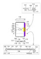
도 18에 나타내어진 바와 같이 탄성부재(340)는 탄성부재 적용부(103) 내측 공간 안에서 일측면이 탄성부재 적용부의 내부 벽면에 지지된 상태에서 반대측 자유단 부분은 탄성력 작용면(310)에 밀착 지지되며 탄성 반발력을 작용시킨다.As shown in FIG. 18, the
탄성력 작용면(310)에 밀착 지지되며 탄성 반발력을 작용시키는 부분은 제1몸체(101a) 또는 제3몸체(101c)의 접힘 및 펼침 상태에 따라 탄성부재 적용부(103) 내측 공간 안에서 움직이고 제1몸체(101a) 또는 제3몸체(101c)가 접힘 상태인 경우 압박되며 수축된 상태를 유지하며 낙하 충격 흡수를 위한 여분의 수축이 가능함이 바람직하다.The elastic
탄성부재(340)의 화면 표시면측 상단 모서리 부분은 플렉시블 디스플레이(10)의 화면 표시면 반대편 면으로서 비접착 상태를 유지하는 부분에 밀착되며 유지될 수 있으며 이 경우 터치 조작시 터치감각을 개선하는 효과는 얻을 수 있으나 장기간의 마찰 발생으로 인해 화면 표시면 반대편 면이 손상되는 문제점이 발생할 수 있다.The upper edge portion of the
따라서 본 발명의 실시 예들에서는 탄성부재(340)의 화면 표시면측 상단 모서리 부분은 플렉시블 디스플레이(10)의 화면 표시면 반대편 면과 Air Gap을 형성하는 상태로 유지되어 직접적인 마찰은 발생치 않고 터치 조작시 눌러지는 플렉시블 디스플레이(10)의 화면 표시면을 탄성부재(340)의 화면 표시면측 상단 모서리 부분이 받쳐주는 상태를 유지할 수 있다.Therefore, in the embodiments of the present invention, the upper edge portion of the
도 30, 도 31, 도 32 및 도 36에 나타내어진 바와 같이 미끄럼 이동판(300)과 달리 미끄럼 이동판(300a, 300b)은 제1몸체(101a) 또는 제3몸체(101c)에 미끄럼 지지될 수 있도록 디스플레이 접착면1(311)의 반대편 면의 힌지 축 방향에 수직하는 양측 모서리 부분에 미끄럼 돌출 지지부(320)가 형성되어있고 미끄럼 돌출 지지부(320)의 일면에는 제1몸체(101a) 또는 제3몸체(101c)에 대한 미끄럼 이동판(300a, 300b)의 미끄럼 고정 기능을 수행할 수 있도록 미끄럼 이동판 고정 장공(321) 형상이 미끄럼 이동 방향의 양측 끝단에 각각 형성되어 있다.As shown in FIGS. 30, 31, 32, and 36, unlike the sliding
미끄럼 이동판(300a, 300b)은 디스플레이 접착면1(311)의 힌지 측 끝단에 개방 형성된 다수의 미끄럼 이동판 개방부(312) 및 힌지 축에 수직인 방향에 위치하는 플렉시블 디스플레이(10)의 끝단이 화면 표시면 밖으로 돌출되지 않도록 디스플레이 접착면1(311)로 부터 플렉시블 디스플레이(10)의 두께 이상으로 돌출된 미끄럼 이동판 돌출부1(313)가 형성되어 있다.The sliding plate (300a, 300b) is a plurality of sliding
미끄럼 이동판(300a, 300b)의 힌지 반대측 부분에는 전방 카메라(360) 및 포토 센서(365), 마이크(364)가 적용되어 있다.A
도 11, 도 17, 도 26, 도 41 및 도 51에 나타내어진 바와 같이 제2몸체(101b)에는 플렉시블 디스플레이(10)의 중간부분 화면 표시면 반대 측 면이 접착 고정되는 면인 디스플레이 접착면2(510)가 일면에 반영되어있고 반대편 일면은 디스플레이 접착면2(510)가 표시장치 지지면2(210)와 동일 평면이 유지되도록 제2몸체(101b)의 일면에 접착 고정 또는 조립되는 고정판(500)이 적용된다.11, 17, 26, 41, and 51, the
디스플레이 접착면2(510)에는 진동 발생기(30)의 고정을 위한 진동 발생기 적용구2(511)가 관통 또는 함몰 형성되어 있다.A vibration generator application tool 2 511 for fixing the
도 11, 도 13 및 도 42에 나타내어진 바와 같이 제1몸체(101a) 및 제3몸체(101c)에는 미끄럼 이동판(300 또는 300a, 300b)의 미끄럼 이동 및 지지를 위해 표시장치 지지면1(110) 측 일면으로부터 몸체 내측면1(111) 측으로 미끄럼 이동판(300 또는 300a, 300b)의 두께 깊이로 함몰 형성된 미끄럼 이동판 지지면1(141)이 형성되어 있으며 베젤형상1(120) 내측 둘레 부분과 미끄럼 이동판 지지면1(141) 사이에는 플렉시블 디스플레이(10)의 화면 표시면 높이와 일치되는 일면인 베젤커버 접착면1(122)이 형성되어있다.11, 13 and 42, the
도 11, 도 13 및 도 42에 나타내어진 바와 같이 미끄럼 이동판 지지면1(141)에는 접힘 및 펼침 수행시 미끄럼 이동판 지지면1(141) 측으로 돌출된 진동 발생기(30) 또는 진동 발생기 적용구1(314)와 미끄럼 이동판 지지면1(141) 사이의 간섭 방지를 위해 진동 발생기 지지 장공(147)이 형성되어있다.As shown in FIGS. 11, 13 and 42, the sliding plate support surface 1 (141) has a vibration generator (30) or a vibration generator application protruding toward the sliding plate support surface 1 (141) when folding and unfolding are performed. To prevent interference between the 1 314 and the sliding
도 14 및 도 43에 나타내어진 바와 같이 제2몸체(101b)에는 표시장치 지지면2(210) 측 일면으로부터 몸체 내측면2(211) 측으로 고정판(500)의 두께 깊이로 함몰 형성된 고정판 접착면(203)이 형성되어 있고, 베젤형상2(220) 내측 둘레 부분과 고정판 접착면(203) 사이에는 플렉시블 디스플레이(10)의 화면 표시면 높이와 일치되는 일면인 베젤커버 접착면2(221)이 형성되어 있다.As shown in FIGS. 14 and 43, the
도 14 및 도 43에 나타내어진 바와 같이 고정판 접착면(203)에는 고정판 접착면(203) 측으로 돌출된 진동 발생기(30) 또는 진동 발생기 적용구2(511)와의 간섭 방지를 위해 진동 발생기 고정구(230)가 형성되어 있다.14 and 43, the fixing plate
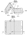
도 11, 도 12, 도 14, 도 41, 도 42 및 도 43에 나타내어진 바와 같이 제1몸체(101a) 및 제3몸체(101b)에는 화면 표시면 측 중앙부분과 힌지 축 부분이 개방된 판상 형태를 갖고 플렉시블 디스플레이(10)의 화면 표시면 측 일측 끝단 둘레를 미끄럼 이동 가능한 상태로 눌러주며 베젤형상1(120)의 내측 둘레 및 베젤커버 접착면1(122)에 고정되는 개방형 베젤커버1(400)이 조립 적용되고 제2몸체(101b)에는 플렉시블 디스플레이(10)의 힌지 축에 수직인 중간 모서리 부분을 덮어주며 플렉시블 디스플레이(10)의 화면 표시면 및 베젤커버 접착면2(221)에 접착 고정되는 한쌍의 베젤커버2(410)가 적용된다.11, 12, 14, 41, 42, and 43, the
개방형 베젤커버1(400)의 힌지 반대측 부분에는 전방 카메라(360) 및 포토 센서(365), 마이크(364)가 적용되어 있다.A
도 12, 도 28, 도 42, 도 52 및 도 53에 나타내어진 바와 같이 제1몸체(101a) 및 제3몸체(101c)에는 탄성부재(340) 및 탄성력 작용면(310)이 적용될 수 있도록 형성된 탄성부재 적용부(103) 및 제어부 구성품들이 적용되며 탄성부재 적용부(103)와 분리되어 형성된 내부공간1(104)이 형성되어 있다.12, 28, 42, 52, and 53, the
도 15, 도 29, 도 43 및 도 54에 나타내어진 바와 같이 제2몸체(101b)에는 구성품들이 적용되는 내부공간2(202)가 형성되어 있다.15, 29, 43, and 54, the
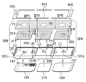
도 26, 도 36 및 도 51에 나타내어진 바와 같이 제1몸체(101a) 및 제3몸체(101c)에는 표시장치 지지면1(110)이 개방 형성된 측으로 적용된 미끄럼 이동판(300a, 300b)의 이탈 방지 및 미끄럼 고정 상태 유지를 위해 미끄럼 이동판 고정 장공(321) 측으로 끝단 돌출 부분이 걸림 될 수 있도록 내부공간1(104)의 벽면을 관통해 적용되는 1개 이상의 미끄럼 고정 가이드(330)가 적용된다.26, 36, and 51, the
미끄럼 고정 가이드(330)가 적용되는 제1몸체(101a) 및 제3몸체(101c)에는 미끄럼 이동판(300a, 300b)의 미끄럼 돌출 지지부(320)에 대한 밀착 지지를 수행할 수 있도록 내부공간1(104)의 내측 벽면 중에서 힌지 축에 수직인 벽면에 마주보며 형성된 미끄럼 이동판 지지대(106), The
슬라이딩 개방구(108)의 개방 형성된 하단면 으로서 미끄럼 이동판(300a, 300b)의 힌지 반대측 끝단 부분을 슬라이딩 지지하는 미끄럼 이동판 지지면1(141), 내부공간1(104)의 힌지 측 벽면부터 힌지 인접 부분에 걸쳐 미끄럼 이동판(300a, 300b)의 힌지 측 끝단 하부면을 지지하는 미끄럼 이동판 지지면2(142) 및 미끄럼 고정 가이드(330)의 적용, 교체 및 돌출 길이 조정을 수행할 수 있도록 내부공간1(104)의 벽면을 관통해 형성된 미끄럼 고정 가이드 적용구(107)가 형성되어 있다.From the hinge side wall surface of the sliding plate support surface 1 (141) and the inner space 1 (104) slidingly supporting the opposite end portions of the sliding plate (300a, 300b) as an open formed lower surface of the sliding opening (108). It is possible to apply, replace, and adjust the protrusion length of the sliding plate supporting surface 2 142 and the sliding fixing
도 19, 도 20, 도 22, 도 47 및 도 49에 나타내어진 바와 같이 제1몸체(101a) 및 제3몸체(101c)의 표시장치 지지면1(110) 연장면과 미끄럼 이동판 지지면1(141) 사이의 공간에는 완전평면 펼침 상태에서 접힘 상태로의 전환시 미끄럼 이동판(300)의 힌지 반대 측 끝단 부분이 힌지 측으로 미끄럼 이동되어 형성된 빈 공간영역인 전방 슬라이딩 영역1(143), 완전평면 펼침 상태를 이룬 후 추가적인 펼침 회전 완료시 미끄럼 이동판(300)의 힌지 반대 측 끝단 부분이 전방 슬라이딩 영역1(143)을 벗어나 힌지 반대 측으로 미끄럼 이동되어 점유되는 공간영역인 전방 슬라이딩 영역2(144) 및 접힘 상태에서 완전 평면 펼침 상태로의 전환시 미끄럼 이동판(300)의 힌지 측 끝단 부분이 힌지 반대 측으로 미끄럼 전진되어 형성된 빈 공간영역인 후방 슬라이딩 영역1(145)이 형성된다.19, 20, 22, 47, and 49, as shown in FIGS. 19, 20, 22, 47, and 49, the display
또한 도 19, 도 20, 도 22 및 도 47에 나타내어진 바와 같이 제1몸체(101a) 및 제3몸체(101c)의 탄성부재 적용부(103)에는 완전평면 펼침 상태를 이룬 후 추가적인 펼침 회전 완료시 미끄럼 이동판(300)의 탄성력 작용면(310)이 후방 슬라이딩 영역1(154)을 벗어나 탄성부재 적용부(103)의 힌지 반대 측 벽면 측으로 미끄럼 전진되어 추가적으로 형성된 빈 공간영역인 후방 슬라이딩 영역2(146)가 형성된다.In addition, as shown in FIGS. 19, 20, 22 and 47, the elastic
도 11, 도 12 및 도 13에 나타내어진 바와 같이 후방 슬라이딩 영역2(146)의 형성을 위해 제1몸체(101a) 및 제3몸체(101c)의 탄성부재 적용부(103)에는 완전평면 펼침 상태를 이룬 후 추가적인 펼침 회전 완료시 미끄럼 이동판(300 또는 300a, 300b)의 탄성력 작용면(310)이 후방 슬라이딩 영역1(145)을 벗어나 탄성부재 적용부(103)의 힌지 반대 측 벽면 측으로 미끄럼 전진될 수 있도록 초과펼쳐짐 섭동 영역부(103a)가 반영되어 있다.11, 12, and 13, for the formation of the rear sliding region 2 146, the
도 35, 도 36, 도 38 및 도 57에 나타내어진 바와 같이 슬라이딩 개방구(108)가 형성되어 있는 제1몸체(101a) 및 제3몸체(101c)의 표시장치 지지면1(110) 연장면과 미끄럼 이동판 지지면2(142) 사이의 공간에는 접힘 상태에서 완전 평면 펼침 상태로의 전환시 미끄럼 이동판(300a, 300b)의 힌지 측 끝단 부분이 힌지 반대 측으로 미끄럼 전진되어 형성된 빈 공간영역인 후방 슬라이딩 영역1(145)이 형성되며 후방 슬라이딩 영역1(145)과 힌지 축 사이에는 별도로 여유 간극이 반영된다.35, 36, 38, and 57, the display
도 40 및 도 60에 간접 적으로 나타내어진 바와 같이 슬라이딩 개방구(108)가 형성되어 있는 제1몸체(101a) 및 제3몸체(101c)에서 형성되는 후방 슬라이딩 영역1(145)은 미끄럼 이동판(300a, 300b)의 미끄럼 이동판 개방부(312)로 인해 단일 직사각형 형태를 유지하지 않고 요철 형태(또는 굴절 형태)로 파편화된 형태를 갖음을 간접적으로 확인 할 수 있다.40 and 60, the
또한 슬라이딩 개방구(108)가 형성되어 있는 제1몸체(101a) 및 제3몸체(101c)의 탄성부재 적용부에는 완전평면 펼침 상태를 이룬 후 추가적인 펼침 회전 완료시 미끄럼 이동판(300a, 300b)의 탄성력 작용면(310)이 후방 슬라이딩 영역1(145)을 벗어나 탄성부재 적용부(103)의 힌지 반대 측 벽면 측으로 미끄럼 전진되어 추가적으로 형성된 빈 공간영역인 후방 슬라이딩 영역2(146)가 형성된다.In addition, the sliding
그리고 도 36 및 도 39에 별도로 도시되지는 않았으나 슬라이딩 개방구(108)가 형성되어 있는 제1몸체(101a) 및 제3몸체(101c)에 적용되는 미끄럼 이동판(300a, 300b)의 미끄럼 이동판 고정 장공(321)의 양측 끝단에는 미끄럼 고정 가이드(330)의 원활한 기능 수행을 위해 전방 슬라이딩 영역2(144)에 대응하는 간섭 방지 형상이 반영되어야 한다. In addition, although not separately shown in FIGS. 36 and 39, the sliding plates of the sliding
도 45 및 도 51에 나타내어진 바와 같이 제1몸체(101a) 또는 제3몸체(101c)의 내부공간1(104)에는 외부저장장치인 SD카드 또는 마이크로 SD카드의 적용위한 SD카드 모듈(180)이 적용되고 제1몸체(101a) 또는 제3몸체(101c)의 경사면1(116)에는 사용자에 의한 SD카드 또는 마이크로 SD카드의 교체 적용을 수행할 수 있는 SD카드 적용구(181)가 형성되어 있다.45 and 51, the
도 2, 도 3, 도 4 및 도 5에 나타내어진 바와 같이 가변 공간(700) 측에 위치되는 제1몸체(101a) 또는 제3몸체(101c) 중 어느 하나의 일면에는 스피커(171)가 적용되어있다.2, 3, 4 and 5, the
도 24, 도 25 , 도 40 및 도 60에 나타내어진 바와 같이 도 2, 도 3, 도 4 및 도 5의 실시 예들에 나타내어진 폴더블 영상표시장치는 고정판(500)을 기준으로 플렉시블 디스플레이(10)가 직사각 영역을 갖는 단일의 비접착 부위와 보다 넓은 직사각 영역을 갖는 단일의 접착 부위가 쌍을 이루며 적용되고 있다.As shown in FIGS. 24, 25, 40, and 60, the foldable image display device shown in the embodiments of FIGS. 2, 3, 4, and 5 is a
비접착 부위를 세분하면 진동판 영역(11) 부분을 제외한 표시장치 지지면1(110) 및 표시장치 지지면2(210)와 같이 상시 밀착을 유지하는 부분, 탄성부재 적용부(103) 영역 중에서 탄성부재(340)의 점유 영역과 탄성부재 고정판(350)에 의해 일부 점유되는 영역을 제외한 영역과 같이 상시 들뜸이 유지되는 부분, 미끄럼 이동판 지지면1(141)의 후방 슬라이딩 영역1(145) 부위 중에서 상시 들뜸이 유지되는 부분을 배제한 나머지 부분과 같이 미끄럼 이동판(300 또는 300a, 300b)의 위치에 따라 밀착과 들뜸 전환이 발생하는 부분으로 나눌 수 있다.If the non-adhesive part is subdivided, the parts that maintain the close contact with each other, such as the display
삼각기둥 접힘 상태fh 유지되는 경우는 완전 평면 펼침 상태보다 상시 밀착부위 비중이 커지고 상시 들뜸 부위 및 전환 발생부위의 비중은 줄어든다.When the triangular prism is maintained in a folded state fh, the specific gravity of the always-closed portion is greater than that of the fully flattened state, and the specific gravity of the always-excited portion and the transition-generating portion is reduced.
터치펜 또는 손가락을 이용해 비접착 부위에 해당하는 화면 표시면을 터치하는 경우 상시 밀착 부위를 터치하는 경우에는 디스플레이 접착면1(311) 및 디스플레이 접착면2(510)과 같은 접착 부위와 동일한 감촉을 얻으나 상시 들뜸 부위 및 전환 부위를 터치하는 경우에는 터치면 하단이 비어있음을 느낄 수 있다.When the screen display surface corresponding to the non-adhesive part is touched using a touch pen or finger, when the permanently touching part is touched, the same texture as the adhesive parts such as display adhesive surface 1 (311) and display adhesive surface 2 (510) When you get or touch the excitement and switching parts at all times, you can feel that the bottom of the touch surface is empty.
이러한 비접착 부위는 힌지 반경(R)이 작아짐에 따라 감소하므로 터치 감각의 향상을 위해서는 힌지 반경(R)을 몸체 두께대비 가능한 작은 값을 하도록 함이 바람직하며 동일한 힌지 반경(R)을 갖는 경우에는 단일의 단순 직사각형 비접착 부위를 갖는 도 24 및 도 25보다 도 40 및 도 60과 같이 굴절 형태의 비접착 부위를 갖도록 하여 비접착 부위를 파편화시켜 터치 감각을 향상시킬 수 있다. Since the non-adhesive portion decreases as the hinge radius (R) decreases, it is preferable to make the hinge radius (R) as small as possible relative to the body thickness in order to improve the touch sense, and in the case of having the same hinge radius (R) It is possible to improve the touch sensation by fragmenting the non-adhesive portion by having the non-adhesive portion of the refractive form as shown in FIGS. 40 and 60 rather than FIGS. 24 and 25 having a single simple rectangular non-adhesive portion.
본 발명인에 의해 제시된 도 2, 도 3, 도 4 및 도 5의 실시예에 나타내어진 폴더블 영상표시장치는 도 19, 도 21 및 도 23에 나타내어진 바와 같이 힌지 축 끝단 부분에 불연속 노출부위가 형성되며 이로 인해 힌지 원주면에 위치되는 플렉시블 디스플레이(10)의 모서리 부분이 보호 수단없이 노출되는 문제가 발생한다.The foldable image display device shown in the embodiments of FIGS. 2, 3, 4 and 5 presented by the present inventor has discontinuous exposed areas at the ends of the hinge shaft as shown in FIGS. 19, 21 and 23. It is formed, which causes a problem that the corner portion of the
접힘 상태에서 보호수단 적용 없이 힌지 축 끝단 방향으로 낙하가 발생되면 플렉시블 디스플레이(10)의 노출된 모서리 부분이 손상을 입는 문제가 발생하게 된다.If a fall occurs in the folded state in the direction of the end of the hinge shaft without applying the protection means in the folded state, a problem occurs in that the exposed edge portion of the
이를 해결하기 위해 본 발명인은 상기 도 2부터 도 5의 실시 예들의 몸체에 모두 적용 가능한 방안을 이하 제시한다.To solve this, the present inventor proposes a method applicable to all of the bodies of the embodiments of FIGS. 2 to 5 below.
도 61은 도 4의 실시예에 힌지 범퍼가 적용된 개념도들 이고, 도 62는 도 5의 실시예에 힌지 범퍼가 적용된 개념도들 이며, 도 63은 도 3의 실시예에 힌지 범퍼가 적용된 접힘 상태에서 낙하되어도 힌지 범퍼에 의해 1차 충격 흡수가 가능함을 보여주는 개념도 이고, 도 64는 도 63의 접힘 상태가 펼침 상태로 전환되어 낙하되어도 힌지 범퍼에 의해 2차 충격 흡수가 가능함을 보여주는 개념도이다.FIG. 61 is a conceptual diagram of a hinge bumper applied to the embodiment of FIG. 4, FIG. 62 is a conceptual diagram of a hinge bumper applied to the embodiment of FIG. 5, and FIG. 63 is a folded state in which the hinge bumper is applied to the embodiment of FIG. 3 It is a conceptual diagram showing that primary shock absorption is possible by the hinge bumper even when it falls, and FIG. 64 is a conceptual diagram showing that secondary shock absorption is possible by the hinge bumper even when the folded state of FIG. 63 is converted to the expanded state and falls.
도 61부터 도 64에 나타내어진 바와 같이 본 발명의 폴더블 영상표시장치는 제어부(20), 접힘 및 펼침이 가능한 플렉시블 디스플레이(10), 플렉시블 디스플레이(10)가 고정 또는 지지되며 모서리 부분에 힌지 관련 형상이 적용되어있는 몸체(100), 힌지 축 끝단에 위치하는 플렉시블 디스플레이의 화면 표시면을 벗어나 몸체(100)의 외부 노출면들 사이의 불연속 부위를 덮으며 힌지 축 끝단에 적용되는 힌지 범퍼(600)를 포함하여 구성된다.As shown in FIGS. 61 to 64, the foldable image display device of the present invention includes a
도 61 및 도 62에 나타내어진 바와 같이 플렉시블 디스플레이(10)의 화면 표시면 측에 위치하는 힌지 범퍼(600)의 바깥 둘레면은 화면 표시면 밖의 영역으로 돌출되는 형상을 갖고, 힌지 범퍼(600)는 고무, 플라스틱 또는 금속 재질을 갖는다.61 and 62, the outer circumferential surface of the
도면에 별도 제시 되지는 않았으나 힌지 범퍼(600), 몸체(100)의 힌지 축 임의 영역에는 힌지 범퍼(600)를 힌지 축 방향으로 누르거나 잡아당기면 제어부(20)에 전기적 신호를 전달 할 수 있는 물리버튼 구성품(미도시) 또는 힌지 범퍼(600)의 회전 수행시 제어부(20)에 회전방향 및 회전정도에 대한 전기적 신호를 전달 할 수 있는 로터리 스위치 또는 광 인터럽트 구성품(미도시)이 포함되어 구성된다.Although not separately provided in the drawings, if the
63 및 도 64에 나타내어진 바와 같이 힌지 범퍼(600)가 적용됨으로 인해 힌지 축 부분으로의 낙하시 1차 충격을 흡수할 수 있고 미끄럼 이동판(300a, 300b)측으로 낙하된 경우에는 여유 간극 및 탄성부재의 작용에 의한 충격 흡수와 반발후 발생하는 2차 충격도 흡수할 수 있다.As shown in 63 and 64, due to the application of the
또한 도 61 및 도 62에 나타내어진 바와 같이 힌지 범퍼(600)의 바깥 둘레가 화면표시면 측 바깥 부분으로 돌출 되있는 특징을 갖으므로 인해 화면 표시면의 손상을 줄 수 있는 지면과의 직접적인 접촉없이 간격을 유지하며 변형된 노트북형 초과펼침 상태로 사용될 수 있거나 완전 평면 펼침 상태에서도 뒤집어 보관될 수 있다.Also, as shown in FIGS. 61 and 62, the outer circumference of the
또한 힌지 축 끝단면에 보여지던 불연속 노출부위도 가려져 미관이 증대되는 부가적인 효과도 얻을 수 있다.In addition, the discontinuous exposed portion shown on the end face of the hinge shaft is also obscured, thereby obtaining an additional effect of increasing the aesthetics.
도 11, 도 26, 도 41, 도 51에 나타내어진 바와 같이 본 발명의 폴더블 영상표시장치 실시 예들은 단일 내부공간을 갖는 기존의 판상형 영상표시장치와 달리 구성품이 적용되는 내부공간이 힌지 축을 기준으로 물리적으로 분리된 3개의 내부공간이 전기적으로 연결 적용되는 특징을 갖는다.11, 26, 41, and 51, the foldable image display device embodiments of the present invention, unlike the conventional plate-shaped image display device having a single interior space, are based on the hinge axis of the interior space to which components are applied. The three physically separated internal spaces are electrically connected and applied.
이를 위해 도 2, 도 3, 도 4 및 도 5에 나타내어진 본 발명의 실시 예인 폴더블 영상표시장치는 도 11, 도 26, 도 41, 도 51에 나타내어진 바와 같이 제어부(20), 플렉시블 디스플레이(10) 및 몸체(100)를 포함하여 구성되는 폴더블 영상표시장치로서 몸체(100)는 플렉시블 디스플레이(10)의 일측 끝단이 고정 또는 지지되며 모서리 부분에 힌지 관련 형상이 적용되어있고 베터리 또는 제어관련 구성품의 적용을 위한 내부공간1(104)이 형성되어있는 제1몸체(101a)와 제3몸체(101c) 및 플렉시블 디스플레이(10)의 중간 부분이 고정 또는 지지되며 일측 모서리가 제1몸체(101a)에 힌지 결합되고 반대편 일측 모서리는 제3몸체(101c)에 힌지 결합되며 베터리 또는 제어관련 구성품의 적용을 위한 내부공간2(202)가 형성되어있는 제2몸체(101b)를 포함하여 구성된다.To this end, the foldable image display device, which is an embodiment of the present invention shown in FIGS. 2, 3, 4 and 5, includes a
도 25, 도 34 및 도 51에 나타내어진 바와 같이 제1몸체(101a)의 내부공간1(104), 제3몸체(101c)의 내부공간1(104) 및 제2몸체(101b)의 내부공간2(202) 중 어느 하나에는 내장형 베터리(160)가 적용되고 내장형 베터리(160)가 적용되지 않은 나머지 내부공간1(104) 또는 내부공간2(202) 중 어느 하나에는 탈부착 베터리(250)가 적용되며 내장형 베터리(160)와 탈부착 베터리(250)는 제어부(20)와 병렬 연결되는 특징을 갖는다.As shown in FIGS. 25, 34, and 51, the
제어부와 내장형 베터리(160) 및 탈부착 베터리(250)가 병렬 연결되는 특징을 가지므로 인해 휴대 무게를 줄이기 위한 경우에는 탈부착 베터리(250)를 내부공간2(202)로부터 제거하고 내장형 베터리(160)만 적용된 상태로 사용해도 되며 이 경우 몸체(100)의 중앙 부분에 위치하는 내부공간2(202)로부터 탈부착 베터리(250)가 제거되었으므로 무게균형은 그대로 유지된다.Since the control unit and the built-in
제어부(20)의 연산장치와 내장형 베터리(160)는 발열관리를 위해 내부공간1(104)과 내부공간2(202) 중 어느 하나에 각각 분리되어 적용됨이 바람직하다.It is preferable that the computing device of the
또한 도 26과 도 51에 나타내어진 바와 같이 탈부착 베터리(250) 및 대용량 탈부착 베터리(250a)에는 기판 경유 지지대(130) 및 기판 경유홈(251)을 경유하는 플렉시블 기판(21)이 베터리 면에 밀려 표시장치 지지면2(210) 밖으로 돌출되지 않도록 플렉시블 기판(21) 두께 이상으로 함몰 형성된 기판 경유홈(251)이 표시장치 지지면2(210)측의 일면에 형성되어 있다.In addition, as shown in FIGS. 26 and 51, the
그리고 내장형 베터리(160)의 그립면1(117)측 끝단 일부분에는 제3몸체(101c)에 적용된 미끄럼 이동판(300b)의 미끄럼 지지를 위해 미끄럼 이동판 지지면1(141)과 동일 평면을 유지하는 단차 형성부(161)가 형성되어있다.And a part of the
도 67에 나타내어진 바와 같이 탈부착 베터리(250)는 노출 부분이 가변 공간(700) 측을 향해 적용되고, 대용량 탈부착 베터리(250a)는 노출 부분이 가변 공간(700)측 안쪽으로 돌출 수용되며 돌출 부분의 모서리는 접힘 상태의 몸체 내측면1(111)과 간섭되지 않는 특징을 갖는다.As shown in FIG. 67, the
도 3 및 도 5에 나타내어진 본 발명의 실시 예인 폴더블 영상표시장치는 힌지 축에 평행한 몸체의 그립면1(117)이 아닌 제2몸체의 힌지 축에 수직인 노출면에 부가장치 적용을 위한 연결 형상이 반영되어 있다.The foldable image display device according to the embodiment of the present invention shown in FIGS. 3 and 5 applies an additional device to the exposed surface perpendicular to the hinge axis of the second body, not the grip surface 1 (117) of the body parallel to the hinge axis. The connection shape for is reflected.
이를 위해 도 3 및 도 5에 나타내어진 바와 같이 본 발명의 실시 예인 폴더블 영상표시장치는 제어부(20), 플렉시블 디스플레이(10) 밈 몸체(100)를 포함하여 구성되는 폴더블 영상표시장치로서 몸체(100)는 플렉시블 디스플레이(10)의 일측 끝단이 고정 또는 지지되며 모서리 부분에 힌지 관련 형상이 적용되어있고 베터리 또는 제어관련 구성품의 적용을 위한 내부공간1(104)이 형성되어있는 제1몸체(101a) 및 제3몸체(101c) 및 플렉시블 디스플레이(10)의 중간 부분이 고정 또는 지지되며 일측 모서리가 제1몸체(101a)에 힌지 결합되고 반대편 일측 모서리는 제3몸체(101c)에 힌지 결합되며 베터리 또는 제어관련 구성품의 적용을 위한 내부공간2(202)가 형성되어있는 제2몸체(101b)를 포함하여 구성된다.For this purpose, as shown in FIGS. 3 and 5, the foldable image display device according to an embodiment of the present invention is a foldable image display device comprising a
도 3, 도 5 및 도 54에 나타내어진 바와 같이 제2몸체(101b)의 힌지 축에 수직인 노출면들 중에서 어느 한쪽의 노출면에는 이어폰 잭 연결을 위한 이어폰 잭 적용구(260)가 형성되어있다.3, 5 and 54, an earphone
또한 제2몸체(101b)의 힌지 축에 수직인 노출면들 중에서 어느 한쪽의 노출면에는 충전 또는 외부연결을 위한 외부연결 적용구(261)가 형성되어있다.In addition, one of the exposed surfaces perpendicular to the hinge axis of the
이어폰 잭 적용구(260) 및 외부연결 적용구(261)를 제2몸체(101b)의 힌지 축에 수직인 노출면인 그립면4(217) 또는 그립면5(218)에 적용하는 이유는 접힘 및 펼침 전환시 기준이 되는 몸체가 제2몸체 이며 제1몸체와 제3몸체의 양손 그립사용 형태가 적용되는 경우 불필요한 간섭을 배제하기 위함이며 이어폰 잭(260) 연결시 무게 균형을 유지하기 위함이다.The reason for applying the
도 2, 도 3, 도 4 및 도 5에 제시된 본 발명인의 폴더블 영상표시장치 실시 예들은 힌지가 적용되어있고 플렉시블 디스플레이(10)가 자체적인 탄성을 갖고 있으며 플렉시블 디스플레이(10)에 간접적으로 탄성력을 작용시키는 탄성부재(340)가 적용되어있다.The embodiments of the foldable image display device of the present inventors shown in FIGS. 2, 3, 4 and 5 are hinged, the
힌지의 회전이 자유로운 특성과 회전을 발생시키는 구동력이 되는 탄성력의 존재로 인해 사용자가 접힘 또는 특정 펼침 상태로의 변경을 통제하는 수단이 적용되어야할 필요성이 존재한다.Due to the free rotation of the hinge and the existence of an elastic force that is a driving force for generating rotation, there is a need for a user to apply a means of controlling folding or changing to a specific unfolding state.
몸체(100)의 내부 공간에 힌지의 선택적인 회전을 억제하고 선택적 허용하는 수단의 적용이 우선적으로 고려 가능하나 내부공간이 협소하여 적용이 어려우며 적용이 된다고 하더라도 기능 구현품의 치수가 매우 작아 가공성, 조립성 및 내구성 확보가 어렵게 된다.It is possible to preferentially consider the application of means for selectively inhibiting and selectively rotating the hinge in the interior space of the
또한 기능 구현품들이 내부공간에 적용되어 있으므로 사용자가 직관적인 통제를 하기도 곤란하며 고장시 수리 또한 어렵게 된다.In addition, since the functional implementations are applied to the interior space, it is difficult for the user to control intuitively, and it is also difficult to repair in case of malfunction.
따라서 본 발명인은 몸체의 내부공간이 아닌 외부 노출면에 사용자가 육안으로 접힘 및 펼침상태 변경에 대한 선택적 통제를 할 수 있는 회전 걸림판이 적용된 폴더블 영상표시장치를 이하 도면들과 함께 제시한다.Therefore, the present inventor provides a foldable image display device with a rotating locking plate that allows a user to selectively control folding and unfolding state changes with the naked eye on an externally exposed surface rather than an internal space of the body, along with the following drawings.
도 65는 도 5의 실시예에 회전 걸림판이 적용되어 제1몸체 또는 제3몸체에 대한 접힘 상태와 완전 평면 펼침 상태에 대한 선택적 걸림을 보여주는 개념도 이고, 도 66은 도 5의 실시예에 회전 걸림판이 적용되어 제1몸체 또는 제3몸체에 대한 초과 펼침 상태에 대한 선택적 걸림을 보여주는 개념도 이다.FIG. 65 is a conceptual view showing a rotational locking plate is applied to the embodiment of FIG. 5 and showing a selective engagement with respect to the folded state and the fully flattened state with respect to the first body or the third body, and FIG. 66 is the rotational engagement with the embodiment of FIG. 5 It is a conceptual diagram showing the selective jamming of the excess unfolded state for the first body or the third body by applying the plate.
도 65 및 도 66에 나타내어진 바와 같이 접힘 및 펼침 상태 전환에 대한 사용자의 선택적 통제가 가능한 폴더블 영상표시장치는 제어부(20), 플렉시블 디스플레이(20), 플렉시블 디스플레이의 일측 끝단이 고정 또는 지지되며 모서리 부분에 힌지 관련 형상이 적용되어있는 제1몸체(101a), 플렉시블 디스플레이(10)가 고정 또는 지지되며 일측 모서리가 제1몸체(101a)에 힌지 결합되는 제2몸체(101b) 및 힌지 축의 끝단에 수직인 제1몸체(101a) 또는 제2몸체(101b)의 외부 노출면들인 그립면들 중 어느 하나의 그립면에 조립 적용되는 선택적 걸림 작용부(도시없음) 및 선택적 걸림 작용부에 결합되어 걸림을 형성하며 선택적 걸림 작용부가 적용된 그립면의 인접 그립면에 적용되는 걸림 돌기(151a, 151b 또는 241)를 포함하여 구성된다.As shown in FIGS. 65 and 66, the foldable image display device capable of the user's selective control over folding and unfolding states is fixed or supported at one end of the
선택적 걸림 작용부는 회전 가능한 상태로 회전 축을 기준으로 조립 적용되고 일측 끝단 부분은 걸림 돌기에 선택적 걸림 형성되는 걸림 형성부 형상이 반영되어있는 회전 걸림판(150 또는 240)을 포함하여 구성되고 걸림 돌기(151a, 161b 또는 241)는 힌지 축으로 부터 간격을 달리해 그립면에 1개이상 분리되어 적용되있는 특징을 갖는다.The optional engaging action part is assembled and applied on the basis of the rotation axis in a rotatable state, and one end portion comprises a rotating
회전 걸림판(150 또는 240)이 적용되는 그립면에는 회전 걸림판(150 또는 240)의 그립면 영역 이탈 방지 및 회전방향 제한위해 돌출방지 형상(152 또는 242)이 적용되어있다.To the grip surface to which the
도 65 및 도 66에 나타내어진 바와 같이 회전 걸림판(150 또는 240)의 회전 중심축과 힌지 축의 거리는 고정 불변이고, 힌지 축과 걸림 돌기(151a, 151b 또는 241)의 거리도 고정불변이며 회전 걸림판1(150)의 회전 중심축과 반대측 끝단 걸림 형성부의 거리도 고정불변이다.65 and 66, the distance between the rotation center axis and the hinge axis of the
회전 걸림판(150 또는 240)의 끝단 걸림 형성부가 걸림 돌기(151a, 151b 또는 241)에 걸림되는 상태로 전환되면 회전 걸림판(150 또는 240)의 회전 중심축, 힌지 축 및 또는 241)로 이루어지는 삼각형이 완성되며 각각 고정불변의 거리를 가지므로 회전 걸림판(150 또는 240)의 걸림이 해제되지 않는 한 제1몸체(101a) 또는 제2몸체(101b)의 회전을 포함한 상태 변경이 불가능해 터치를 포함한 외력이 작용해도 펼침 상태가 유지된다.When the end jamming portion of the
또한 도 65 및 도 66에 나타내어진 바와 같이 회전 걸림판(150)과 회전 걸림판(240)의 회전 방향은 서로 상이하며 이는 돌출방지 형상(152 또는 242)에 기인한다.In addition, as shown in FIGS. 65 and 66, the rotation directions of the
그리고 회전 걸림판(150 또는 240)이 적용되는 및 제2몸체(101b)의 그립면에는 사용자의 외력이 회전 걸림판(150 또는 240)에 작용되는 경우에만 회전이동 될 수 있도록 회전 걸림판(150 또는 240)의 두께보다 낮은 높이로 형성된 경사 걸림턱(미도시)이 회전 개시 앞부분에 형성되어있음이 바람직하다.In addition, the
회전 걸림판(150)은 걸림 형성시 화면 표시면측을 향하여 회전하고 회전 걸림판(240)은 걸림 형성시 몸체 내측면2(211)측을 향하여 회전한다.The
회전 걸림판(150)이 적용되는 그립면에는 걸림 돌기(151a)로부터 걸림 해제된 회전 걸림판(150)의 걸림 형성부가 제1몸체의 접힘 회전에 의해 가이드되며 수납위치로 회전시키는 기능을 수행하는 형상인 회전 걸림판 가이드(244)가 일정 길이로 돌출 형성되어있다.On the grip surface to which the
도 68은 슬라이딩 개방구가 그립면1에 형성된 도 3 및 도 5의 실시예가 도 2 및 도 4의 실시예 보다 넓은 표시화면을 제공할 수 있음을 보여주는 개념도 이다.68 is a conceptual view showing that the embodiments of FIGS. 3 and 5 in which the sliding opening is formed on the
도 2 및 도 4의 실시예의 폴더블 영상표시장치는 도 3 및 도 5의 실시예의 폴더블 영상표시장치와 달리 슬라이딩 개방구(108)가 적용되어있지 않아 미끄럼 이동판(300)이 그립면1(117)을 벗어날 수가 없다.2 and 4, unlike the foldable image display device of the embodiment of FIGS. 3 and 5, the sliding
반면 도 3 및 도 5의 실시예의 폴더블 영상표시장치는 미끄럼 이동판(300a, 300b)가 그립면1(117)을 벗어나 접힘시 생성되고 펼침시 소멸되는 힌지 원주면 부분을 개방형 베젤 커버1(400)에 숨기지 않고 자연스럽게 노출 시킴으로 인해 도 68과 같은 넓은 표시화면을 가능케 한다.On the other hand, in the foldable image display device of the embodiment of FIGS. 3 and 5, the sliding circumferential portion of the hinge circumferential surface, which is generated when folded out of the
도 69는 도 2 부터 도 5의 실시예가 다양한 상태로 활용될 수 있음을 보여주는 개념도 이다.69 is a conceptual view showing that the embodiments of FIGS. 2 to 5 can be utilized in various states.
도 69에 나타내어진 사용예들은 본 발명의 실시예인 폴더블 영상표시장치가 단일 힌지가 아닌 2개의 힌지가 적용되고 노트북형 초과펼쳐짐이 가능한 구조를 갖고 있음으로 인해 가능하다.The use examples shown in FIG. 69 are possible because the foldable image display device according to the embodiment of the present invention has a structure in which two hinges are applied, rather than a single hinge, and a notebook-type over-expansion is possible.
또한 도시되지는 않았으나 바지 뒷주머니에 펼침 상태로 넣고 다녀도 자연스럽게 엉덩이 곡률에 대응하여 접힘이 가능하므로 판상형 영상표시장치와 같이 바지 뒷주머니에 넣고 않을 경우 파손될 위험성도 없게 된다.Also, although not shown, it is possible to fold in response to the curvature of the hip even if it is put in an open state on the back pocket of the pants, so there is no risk of damage if it is not placed in the back pocket of the pants, such as a plate-shaped image display device.
도 70은 도 2 부터 도 5의 실시예의 가변 공간에 무선이어폰 및 터치펜이 적용될 수 있음을 보여주는 사시도 및 평면도 이다.70 is a perspective view and a plan view showing that a wireless earphone and a touch pen can be applied to the variable spaces of the embodiment of FIGS. 2 to 5.
도 70에 나타내어진 바와 같이 도 2부터 도 5의 실시 예들인 폴더블 영상표시장치는 접힘 상태시 형성되고 펼침시 소멸하는 가변 공간(700)을 AI 스피커의 저음 공명통으로 활용하는 기능 외에도 블루투스 이어폰(710) 및 접이식 터치펜(720)의 수납공간으로 활용할 수도 있다.As shown in FIG. 70, the foldable image display device of the embodiments of FIGS. 2 to 5 is a Bluetooth earphone (in addition to the function of utilizing the
가변 공간(700)에 수납되어있는 블루투스 이어폰(710)을 사용하고자 할 경우에는 펼침 상태로 전환하고 몸체 내측면1(111)측에 적용된 탄성 수납 밴드(191)에 고정되어있는 블루투스 이어폰(710)을 빼내어 사용하기만 하면 된다.In order to use the
이러한 사용방법이 적용되는 경우 별도의 블루투스 이어폰 케이스를 들고 다니지 않아도 되며 즉시 수납 인출 사용이 가능한 편리성도 얻게된다.When this method of use is applied, there is no need to carry a separate Bluetooth earphone case, and the convenience of being able to immediately use the storage is also obtained.
도 71은 도 3 및 도 5의 실시예에 적용된 가변 공간 및 미끄럼 이동판(300a, 300b)이 방열 기능을 수행함을 보여주는 개념도 이다.71 is a conceptual view showing that the variable space and the sliding
도 71에 나타내어진 바와 같이 가변 공간(700)은 공명통 기능과 수납 공간 기능 외에도 제어부와 베터리에서 발생하는 열을 방출 시키는 통로 기능을 수행할 수 있다.As shown in FIG. 71, the
가변 공간을 형성하지 않고 면 밀착 접힙되는 경우에는 접힘 상태시 손으로 그립하고 있으면 열이 배출되는 공간이 제한되지만 삼각기둥 형상의 가변 공간이 형성되는 도 2부터 도 5의 실시 예들의 폴더블 영상장치는 사용자가 그립하고 있어도 중앙 부분에 통기가 가능한 구조를 갖고잇어 방열 기능이 뛰어남을 알 수 있다.In the case of being folded in close contact without forming a variable space, the space in which heat is discharged is limited when gripped by hand in the folded state, but the foldable imaging device of the embodiments of FIGS. 2 to 5 in which a variable space in the form of a triangular prism is formed It shows that it has excellent heat dissipation function because it has a structure that can be ventilated in the central part even if the user is gripping it.
또한 도 2 및 도 4의 실시예의 경우 미끄럼 이동판(300)은 제1몸체(101a) 및 제3몸체(101c) 내측 공간에 갇혀있어 내부공간1(104)의 제어부에 의해 발생하는 열을 배출하는 기능이 제한적이나 도 3 및 도 5의 실시예의 미끄럼 이동판(300a, 300b)은 일측 끝단이 제1몸체(101a) 및 제3몸체(101c)를 벗어나 상대적으로 차가운 영역에 존재해 제어부에 의해 발생하는 열을 배출하는 열 배출 전달자 기능을 수행한다.In addition, in the embodiment of FIGS. 2 and 4, the sliding
도 72는 도 3 및 도 5의 실시예에 적용된 미끄럼 이동판에 손바닥을 이용해 외력을 작용하면 플렉시블 디스플레이의 미접착 부위가 융기되어 솟아 올라옴을 보여주는 개념도 이다.FIG. 72 is a conceptual view showing that an unadhesive portion of a flexible display rises and rises when an external force is applied to the sliding moving plate applied to the embodiments of FIGS. 3 and 5 using a palm.
도 72에 나타내어진 바와 같이 도 3 및 도 5에 제시된 본 본 발명의 실시 예들인 폴더블 영상표시장치는 그립하고 있던 손을 떼어서 화면 표시면을 터치조작 하지 않고 그립하고 있던 상태로도 손가락의 터치 조작 없이도 네비게이션 조작을 할 수 있는 사용례를 보여준다.As shown in FIG. 72, the foldable image display device according to the embodiments of the present invention shown in FIGS. 3 and 5 releases the gripped hand and touches the finger even when the grip is performed without touching the screen display surface. It shows a use case that can be used for navigation without manipulation.
플렉시블 디스플레이(10)에는 폴더블 기능과 함께 화면 표시면의 터치시 압력변화를 감지하는 압력감지 터치패널(도시생략)이 적용되고 제1몸체(101a) 또는 제3몸체(101c)가 완전 평면 펼침 상태시 슬라이딩 개방구(108)를 경유하여 그립면1(117) 밖으로 돌출되는 미끄럼 이동판(300a, 300b)의 끝단을 사용자가 그립하고 있던 손바닥의 안쪽 면을 이용해 힌지 측으로 눌러주면 후방 슬라이딩 영역1(145) 또는 후방 슬라이딩 영역2(146)에 위치하는 플렉시블 디스플레이(10)의 미접착 부분에서 순간적으로 형성되는 융기 곡면에 의한 압력변화를 압력감지 터치패널이 감지해 제어부에 전달하는 기능을 갖는다.The
미끄럼 이동판(300a, 300b)의 끝단부 누름에 의해 사용자의 이벤트를 감지한 제어부는 이 입력값이 제1몸체(101a) 또는 제3몸체(101c)의 회전에 의한 미끄럼 이동판(300a, 300b) 이동 관련된 입력값 인지를 비교 판단하고 힌지 축 회전 감지 센서(135)에서 입력된 제1몸체(101a) 또는 제3몸체(101c)의 유의미한 회전 입력이 없으면 미끄럼 이동과 무관한 미끄럼 이동판(300a, 300b)의 순간적인 끝단부 누름이라고 판정하고 순간적인 끝단부 누름 이벤트에 대한 이벤트 루틴을 실시한다.The control unit that detects the user's event by pressing the end portions of the sliding
상기의 도 72에 적용된 개념은 완전 평면 펼침 상태에서 미끄럼 이동판(300a, 300b) 모서리로의 낙하가 발생시 미끄럼 이동판(300a, 300b)이 힌지 측 방향으로 낙하 충격을 흡수하며 후퇴되는 기능으로도 작용해 낙하 충격에 대한 저항성이 높아지는 부수적인 효과도 얻을 수 있다.The concept applied to FIG. 72 is also a function in which the sliding
도 73은 도 3 및 도 5 실시예의 완전 평면 펼침 상태에서 제1몸체 또는 제3몸체의 어느 한쪽에 회전력을 가하면 힌지 축 회전 감지 센서가 회전 량을 감지할 수 있음을 보여주는 개념도 이다.73 is a conceptual diagram showing that the hinge axis rotation detection sensor can detect the amount of rotation when a rotational force is applied to either the first body or the third body in the fully flattened state of the embodiments of FIGS. 3 and 5.
도 73에 나타내어진 바와 같이 도 2, 도 3, 도 4 및 도 5에 제시된 본 본 발명의 실시 예들인 폴더블 영상표시장치는 제1몸체(101a) 및 제3몸체(101c)를 양손으로 그립하고 있는 사용자가 일측의 회전 걸림판(240)을 걸림 해제시켜 선택적인 회전조작이 가능하게 한 후 기판 지지대 적용부(105)에 적용된 힌지 축 회전 감지 센서(135)를 이용해 사용자에 의한 허ㅏ면 표시면 위측 방향으로의 회전변위 발생 또는 아래측 방향 회전변위를 감지하고 해당변위 상태의 지속여부를 감지하여 이를 제어부에 전달하고 이를 통해 터치조작에 의한 네비게이션 조작이 아닌 손바닥 자체의 꺽임에 의한 네비게이션 수행을 가능하게 해준다. As shown in FIG. 73, the foldable image display device according to the embodiments of the present invention shown in FIGS. 2, 3, 4 and 5 grips the
도 74는 초과 펼침 회전시 고정되지 않은 플렉시블 디스플레이의 끝단이 힌지 영역 겹침으로 인해 밀림 이동이 발생함을 보여주는 개념도이다.74 is a conceptual diagram showing that the edge of the flexible display that is not fixed when the over-unfolding is rotated causes a sliding movement due to overlapping of the hinge region.
도 74에 나타내어진 바와 같이 힌지 반경(R)이 몸체 두께(T)와 비슷한 단일 힌지 적용 영상표시장치의 경우에는 접힘 및 펼침시 힌지 원주면의 생성 및 소멸이 발생하고 이에 따라 베젤 간극(K) 안쪽의 몸체 내측 부분에서 플렉시블 디스플레이 끝단의 미끄럼 이동이 발생된다.As shown in FIG. 74, in the case of a single hinge-applied image display device having a hinge radius R similar to the body thickness T, the creation and disappearance of the circumferential surface of the hinge occurs when folded and unfolded, and accordingly, the bezel gap K The sliding movement of the end of the flexible display occurs in the inner part of the inner body.
접힘 상태에서 부터 완전 평면 펼침 상태로 전환되는 경우 미끄럼 이동양(A)은 아래의 관계를 갖으며 힌지 반경(R) 또는 접힘각도(Y)를 줄이면 정률적으로 줄어드는 특성이 존재한다.When switching from the folded state to the fully flattened state, the sliding amount (A) has the following relationship, and when the hinge radius (R) or the folding angle (Y) is reduced, there is a property that it decreases in a fixed rate.
미끄럼 이동양(A)=힌지 반경(R) x 접힘각도(Y)Amount of sliding (A) = hinge radius (R) x folding angle (Y)
또한 완전 평면 펼침 상태를 이룬 후 노트북형의 초과펼침 상태에서는 힌지 원주면 부위의 힌지 영역 겹침 발생으로 인해 플렉시블 디스플레이(10) 끝단의 추가적인 미끄럼 이동이 발생하여 플렉시블 디스플레이(10) 끝단이 베젤 간극(K)을 벗어나는 현상이 발생된다.In addition, after the fully flat unfolded state, in the excessive unfolded state of the notebook type, additional sliding movement of the end of the
초과펼침 미끄럼 이동량(C)은 힌지반경(R) 또는 초과펼침 회전각도와 정률적인 관계는 성립하지 않으나 초과펼침 회전각도가 증대됨에 따라 힌지영역 겹침양도 증가하여 함께 증대되는 특성을 갖는다.The amount of sliding of the over-expanded sliding (C) does not establish a constant relationship with the hinge radius (R) or the over-expanding rotational angle, but has the characteristic that the amount of overlapping of the hinge region increases as the over-expanding rotational angle increases.
도 74에 초과펼침 미끄럼 이동량(C)을 C가 아닌 2C로 표기한 것은 어느 한쪽 몸체쪽으로는 초과펼침 미끄럼 이동이 불가능하여 반대편 몸체측에서 초과펼침 미끄럼 이동량이 누적되어 발생됨을 표시한 것이고 만일 양쪽 몸체 모두에서 균등하게 초과펼침 미끄럼 이동이 가능한 경우에는 각각의 몸체 끝단 쪽에서 그 절반인 C값으로 발생 표시되어야 한다.The over-expanded sliding amount (C) in FIG. 74 is indicated as 2C rather than C, indicating that the over-expanded sliding amount is accumulated on the opposite side of the body because the over-expanded sliding is impossible to either body. If it is possible to over-slip evenly across all of them, it should be generated and marked as half of the value of C at the end of each body.
그리고 완전 평면 펼침 상태시 힌지 부위 하단에 힌지 원주면이 돌출 유지되는 문제점과 더불어 힌지 부위에서의 불연속 부위 노출 문제점이 존재하나, 힌지 존재로 인해 평면 유지 능력은 무힌지 적용 아웃폴딩 영상표시장치 보다는 좋다.In addition, there is a problem in that the circumferential surface of the hinge is protruded and maintained at the bottom of the hinge portion in a fully flattened state, and there is a problem in exposing the discontinuous portion in the hinge region. .
도 74와 달리 도 2, 도 3, 도 4 및 도 5에 제시한 폴더블 영상표시장치(1)는 180도 완전 접힘이 아닌 둔각의 텐트형 접힘을 적용하여 접힘각도(Y)를 1/3정도 줄임으로 인해 플렉시블 디스플레이(10) 끝단의 미끄럼 이동양(A)을 정률적으로 1/3 줄인다.Unlike FIG. 74, the foldable
또한 도 2 및 도 3에 제시한 폴더블 영상표시장치(1)는 몸체 두께 대비 힌지 반경(R)을 감소시켜 힌지 반경(R) 감소 비율만큼 미끄럼 이동양(A)이 정율적으로 줄어드는 효과도 추가적으로 얻는다.In addition, the foldable
그리고 도 2, 도 3, 도 4 및 도 5에 제시한 폴더블 영상표시장치(1)는 초과펼침 미끄럼 이동량(C) 또한 힌지 반경(R)이 줄어듬에 따라 힌지영역 겹침량도 감소되나 정률적인 감소 특성을 보이지는 않는다.In addition, the foldable
또한 몸체 두께 대비 힌지 반경(R)의 감소 및 접힘 각도(Y)의 1/3 정도 감소를 이루는 접힘 방식이 적용됨으로 인해 힌지 축 끝단 부위에서 발생하는 불연속 노출부위도 감소된다.In addition, since the folding method, which reduces the hinge radius (R) and the folding angle (Y) by about 1/3 of the body thickness, is applied, the discontinuous exposed portion generated at the end portion of the hinge shaft is also reduced.
이상, 첨부된 도면들을 참조하여 본 발명의 실시 예들을 설명하였지만, 본 발명이 속하는 기술분야에서 통상의 지식을 가진 자는 본 발명이 그 기술적 사상이나 필수적인 특징을 변경하지 않고서 다른 구체적인 형태로 실시될 수 있다는 것을 이해할 수 있을 것이다. 그러므로 이상에서 기술한 실시예들에는 모든 면에서 예시적인 것이며 한정적이 아닌 것으로 이해해야만 한다.The embodiments of the present invention have been described above with reference to the accompanying drawings, but those skilled in the art to which the present invention pertains can be implemented in other specific forms without changing the technical spirit or essential features of the present invention. You will understand that there is. Therefore, it should be understood that the embodiments described above are illustrative in all respects and not restrictive.
첨부된 도면들의 주요부위에 대한 부호를 설명하면 다음과 같다.
1: 폴더블 영상표시장치
10: 플렉시블 디스플레이
11: 진동판 영역
20: 제어부
21: 플렉시블 기판
22: 표시장치 연결 기판
30: 진동 발생기
100: 몸체
101a: 제1몸체
101b: 제2몸체
101c: 제3몸체
102: 경로 관통구1
103: 탄성부재 적용부
103a: 초과펼쳐짐 섭동 영역부
104: 내부공간1
105: 기판 지지대 적용부
106: 미끄럼 이동판 지지대
107: 미끄럼 고정 가이드 적용구
108: 슬라이딩 개방구
109: 디스플레이 콘넥터 경유구
110: 표시장치 지지면1
111: 몸체 내측면1
112: 힌지 원주면1
113: 접힘 지지면1
114: 접힘 지지면2
115: 접힘 지지면5
116: 경사면1
117: 그립면1
118: 그립면2
119: 그립면3
120: 베젤형상1
121: 베젤 간섭 방지부1
122: 베젤커버 접착면1
130: 기판 경유 지지대
131: 기판 경유 원주면1
132: 기판 경유 상부면1
133: 기판 경유 하부면1
134: 적용면
135: 힌지 축 회전 감지 센서
141: 미끄럼 이동판 지지면1
142: 미끄럼 이동판 지지면2
143: 전방 슬라이딩 영역1
144: 전방 슬라이딩 영역2
145: 후방 슬라이딩 영역1
146: 후방 슬라이딩 영역2
147: 진동 발생기 지지 장공
150: 회전 걸림판
151a: 걸림 돌기
151b: 걸림 돌기
152: 돌출방지 형상
161: 단차 형성부
170: 후면 카메라 모듈
171: 스피커
180: SD카드 모듈
181: SD카드 적용구
190: 덮개판1
191: 탄성 수납 밴드
201: 경로 관통구2
202: 내부공간2
203: 고정판 접착면
204: 플렉시블 기판 경유부
210: 표시장치 지지면2
211: 몸체 내측면2
212: 힌지 원주면2
213: 접힘 지지면3
214: 접힘 지지면4
215: 접힘 지지면6
216: 경사면2
217: 그립면4
218: 그립면5
220: 베젤형상2
221: 베젤커버 접착면2
222: 베젤 간섭 방지부2
230: 진동 발생기 고정구
240: 회전 걸림판
241: 걸림 돌기
242: 돌출방지 형상
243:
244: 회전 걸림판 가이드
250: 탈부착 베터리
250a: 대용량 탈부착 베터리
251: 기판 경유홈
260: 이어폰 잭 적용구
261: 외부연결 적용구
270: 덮개판2
300: 미끄럼 이동판
300a: 미끄럼 이동판
300b: 미끄럼 이동판
310: 탄성력 작용면
311: 디스플레이 접착면1
312: 미끄럼 이동판 개방부
313: 미끄럼 이동판 돌출부1
314: 진동 발생기 적용구1
314a: 진동 발생기 적용구1
320: 미끄럼 돌출 지지부
321: 미끄럼 이동판 고정 장공
330: 미끄럼 고정 가이드
340: 탄성부재
350: 탄성부재 고정판
360: 전방 카메라
361: 내장 안테나
362: 지문 스캐너
363: 통화 스피커
364: 마이크
365: 포토 센서
400: 개방형 베젤커버1
410: 베젤커버2
500: 고정판
510: 디스플레이 접착면2
511: 진동 발생기 적용구2
511a: 진동 발생기 적용구2
600: 힌지 범퍼
700: 가변 공간
710: 블루투스 이어폰
720: 접이식 터치펜The reference numerals for the main parts of the attached drawings are as follows.
1: foldable video display device 10: flexible display
11: diaphragm area
20: control unit 21: flexible substrate
22: display connection board 30: vibration generator
100:
101b:
102: path through
103a: excess unfolding perturbation area 104:
105: substrate support application part 106: sliding plate support
107: sliding fixing guide application port 108: sliding opening
109: Display connector via 110:
111: body
113: folded
115: folded support surface 5 116:
117: grip face 1 118: grip face 2
119: Grip surface 3 120:
121: bezel
130: support via substrate 131: circumferential surface via
132: upper surface via
134: applied surface 135: hinge axis rotation detection sensor
141: sliding
142: sliding plate support surface 2 143:
144: front sliding area 2 145:
146: rear sliding area 2 147: vibration generator support long hole
150: rotating
151b: jam projection 152: protruding shape
161: step forming portion 170: rear camera module
171: speaker 180: SD card module
181: SD card application port 190:
191: elastic storage band 201: path through hole 2
202: interior space 2 203: fixing plate adhesive surface
204: flexible substrate via portion 210: display device support surface 2
211: Body inner surface 2 212: Hinge circumferential surface 2
213: folded support surface 3 214: folded support surface 4
215: folded
217: grip face 4 218: grip face 5
220: bezel shape 2 221: bezel cover adhesive surface 2
222: bezel interference prevention unit 2 230: vibration generator fixture
240: rotating jam plate 241: jam projection
242: protrusion prevention shape 243:
244: rotating stop plate guide 250: removable battery
250a: Large-capacity removable battery 251: Groove via substrate
260: earphone jack application port 261: external connection application port
270: cover plate 2
300: sliding
300b: sliding plate 310: elastic force acting surface
311: display
313: sliding
314a: vibration
321: sliding plate fixing long hole 330: sliding fixing guide
340: elastic member 350: elastic member fixing plate
360: front camera 361: built-in antenna
362: fingerprint scanner 363: call speaker
364: microphone 365: photo sensor
400:
500: Fixing plate 510: Display bonding surface 2
511: vibration generator application port 2 511a: vibration generator application port 2
600: hinge bumper 700: variable space
710: Bluetooth earphone 720: Folding touch pen
Claims (26)
몸체는 플렉시블 디스플레이의 일측 끝단이 고정 또는 지지되며 모서리 부분에 힌지 관련 형상이 적용되어있는 제1몸체 및 제3몸체; 및
플렉시블 디스플레이의 중간 부분이 고정 또는 지지되며 일측 모서리가 제1몸체에 힌지 결합되고 반대편 일측 모서리는 제3몸체에 힌지 결합되는 제2몸체;를 포함하여 구성되며
제2몸체에 대한 제1몸체 및 제3몸체 모두 접힘시 형성되고 어느 하나의 펼침시 사라지는 삼각기둥 형상의 가변 공간을 형성하는 특징을 갖는 폴더블 영상표시장치.A foldable image display device comprising a flexible display and a body,
The body is fixed or supported at one end of the flexible display, and the first body and the third body to which the hinge-related shape is applied to the edge portion; And
The middle part of the flexible display is fixed or supported, and one edge is hinged to the first body and the other edge is hinged to the third body.
A foldable image display device having a feature of forming a variable space of a triangular prism shape that is formed when the first body and the third body with respect to the second body are folded and disappear when unfolded.
제1몸체 및 제3몸체의 힌지 축에 수직인 일부분 형상은 플렉시블 디스플레이의 화면표시면 반대측 면이 직접 또는 간접 고정되거나 지지되는 평면인 표시장치 지지면1;
표시장치 지지면1의 반대측 노출면을 이루는 몸체 내측면1;
표시장치 지지면1과 접하는 상태로 힌지 원주면을 따라 곡면 형성된 힌지 원주면1;
힌지 원주면1과 접하거나 또는 연결된 상태로 표시장치 지지면1의 반대측 면에 위치되는 접힘 지지면1; 및
접힘 지지면1의 끝단과 몸체 내측면1을 연결하여 형성되며 접힘 지지면1에 접하지 않는 접힘 지지면2;를 포함하며
이에 대응하는 제2몸체의 힌지 축에 수직인 일부분 형상은 플렉시블 디스플레이의 평면 펼침시 표시장치 지지면1과 동일 평면을 이루는 표시장치 지지면2;
표시장치 지지면2의 반대측 노출면을 이루는 몸체 내측면2;
일측 끝단은 몸체 내측면2의 힌지 측 끝단에 연결되고 반대측 끝단은 제1몸체와 제2몸체 또는 제3몸체와 제2몸체의 접힘 상태시 제2몸체에 위치되는 제1몸체 또는 제3몸체의 접힘 지지면2에 접촉되거나 마주 보며 위치되는 접힘 지지면4; 및
제1몸체와 제2몸체 또는 제3몸체와 제2몸체의 접힘 상태시 제2몸체의 힌지 측에 위치되는 제1몸체 또는 제3몸체의 접힘 지지면1의 연장면에 해당되는 접힘 지지면6;을 포함하는 형상을 갖는 폴더블 영상표시장치.According to claim 1,
Partial shapes perpendicular to the hinge axes of the first body and the third body include a display device support surface 1 on which the opposite sides of the flexible display screen are directly or indirectly fixed or supported;
A body inner surface 1 constituting an exposed surface opposite to the display device support surface 1;
A hinge circumferential surface 1 curved along a circumferential surface of the hinge in contact with the display device support surface 1;
A folded support surface 1 positioned on the opposite side of the display device support surface 1 in contact with or connected to the hinge circumferential surface 1; And
It is formed by connecting the end of the folded support surface 1 and the inner surface of the body 1, and includes a folded support surface 2 that does not contact the folded support surface 1;
The corresponding shape of the part perpendicular to the hinge axis of the second body includes a display support surface 2 that forms the same plane as the display support surface 1 when the flexible display is unfolded;
A body inner surface 2 constituting an exposed surface opposite to the display device support surface 2;
One end is connected to the hinge side end of the inner side of the body 2, and the other end is the first body or the third body located in the second body when the first body and the second body or the third body and the second body are folded. A folding support surface 4 which is in contact with or facing the folding support surface 2; And
When the folded state of the first body and the second body or the third body and the second body is folded, the folded support surface corresponding to the extended surface of the folded support surface 1 of the first body or the third body located on the hinge side of the second body 6 Foldable image display device having a shape including a.
제2몸체의 힌지 축선상 다른 위치에 수직인 일부분 형상은 표시장치 지지면2;
몸체 내측면2;
표시장치 지지면2와 접하는 상태로 힌지 원주면을 따라 곡면 형성된 한쌍의 마주보며 위치되는 힌지 원주면2;
힌지 원주면2와 접하거나 또는 연결된 상태로 표시장치 지지면2의 반대측 면을 이루고 마주보며 위치되는 한쌍의 접힘 지지면3; 및
접힘 지지면3의 끝단과 몸체 내측면2를 연결하여 형성되며 접힘 지지면3에 접하지 않고 마주보며 위치되는 한쌍의 접힘 지지면4;를 포함하고
이에 대응하는 제1몸체 및 제3몸체의 힌지 축에 수직인 일부분 형상은 표시장치 지지면1;
접힘 지지면2;
제1몸체와 제2몸체 또는 제3몸체와 제2몸체의 접힘 상태시 제1몸체 또는 제3몸체의 내측에 위치되는 제2몸체의 접힘 지지면3의 연장면에 해당되는 접힘 지지면5; 및
몸체 내측면1;을 포함하는 형상을 갖는 폴더블 영상표시장치.According to claim 2,
A partial shape perpendicular to another position on the hinge axis of the second body includes a display device support surface 2;
Body inner surface 2;
A hinge circumferential surface 2 positioned opposite the pair of curved surfaces formed along the circumferential surface of the hinge in contact with the display device support surface 2;
A pair of folded support surfaces 3 facing and positioned opposite to each other of the display device support surface 2 in contact with or connected to the hinge circumferential surface 2; And
It is formed by connecting the end of the folded support surface 3 and the inner surface of the body 2, and includes a pair of folded support surfaces 4 that are positioned facing each other without contacting the folded support surface 3;
Partial shapes perpendicular to the hinge axis of the first body and the third body corresponding to the display device support surface 1;
Folded support surface 2;
A folding support surface 5 corresponding to an extended surface of the folding support surface 3 of the second body positioned inside the first body or the third body when the first body and the second body or the third body and the second body are folded; And
Foldable image display device having a shape including a body inner surface 1;
제1몸체 및 제3몸체의 힌지 축에 수직인 일부분 형상은 플렉시블 디스플레이의 화면표시면 반대측 면이 직접 또는 간접 고정되거나 지지되는 평면인 표시장치 지지면1;
표시장치 지지면1과 접하는 상태로 힌지 원주면을 따라 곡면 형성된 힌지 원주면1;
표시장치 지지면1의 반대측 노출면을 이루며 힌지 원주면1에 접하는 몸체 내측면1;을 포함하며
이에 대응하는 제2몸체의 힌지 축에 수직인 일부분 형상은 플렉시블 디스플레이의 평면 펼침시 표시장치 지지면1과 동일 평면을 이루는 표시장치 지지면2;
표시장치 지지면2의 반대측 노출면을 이루는 몸체 내측면2; 및
표시장치 지지면2와 몸체 내측면2를 연결하고 제1몸체와 제2몸체 또는 제3몸체와 제2몸체의 접힘 상태시 제2몸체의 힌지 측에 위치되는 제1몸체 또는 제3몸체의 몸체 내측면1에 접촉되거나 마주보며 위치되는 접힘 지지면6;을 포함하는 형상을 갖는 폴더블 영상표시장치.According to claim 1,
A partial shape perpendicular to the hinge axis of the first body and the third body includes a display device support surface 1 on which the opposite sides of the flexible display screen are directly or indirectly fixed or supported;
A hinge circumferential surface 1 curved along a circumferential surface of the hinge in contact with the display device support surface 1;
Includes a body inner surface 1; which forms an exposed surface opposite to the display device support surface 1 and is in contact with the hinge circumferential surface 1.
The corresponding shape of the part perpendicular to the hinge axis of the second body includes a display support surface 2 that forms the same plane as the display support surface 1 when the flexible display is unfolded;
A body inner surface 2 constituting an exposed surface opposite to the display device support surface 2; And
The body of the first body or the third body, which is connected to the display device support surface 2 and the body inner surface 2 and is positioned on the hinge side of the second body when the first body and the second body or the third body and the second body are folded. A foldable image display device having a shape including; a folding support surface 6 which is located in contact with or facing the inner surface 1;
제2몸체의 힌지 축선상 다른 위치에 수직인 일부분 형상은 표시장치 지지면2;
몸체 내측면2;
표시장치 지지면2와 접하는 상태로 힌지 원주면을 따라 곡면 형성된 한쌍의 마주보며 위치되는 힌지 원주면2; 및
표시장치 지지면2의 반대측 노출면을 이루며 힌지 원주면2에 접하는 몸체 내측면2;를 포함하며
이에 대응하는 제1몸체 및 제3몸체의 힌지 축에 수직인 일부분 형상은 표시장치 지지면1;
몸체 내측면1; 및
표시장치 지지면1과 몸체 내측면1을 연결하고 제1몸체와 제2몸체 또는 제3몸체와 제2몸체의 접힘 상태시 제1몸체 또는 제3몸체의 내측에 위치되는 제2몸체의 몸체 내측면2에 접촉되거나 마주보며 위치되는 접힘 지지면5;를 포함하는 형상을 갖는 폴더블 영상표시장치.The method of claim 4,
A partial shape perpendicular to another position on the hinge axis of the second body includes a display device support surface 2;
Body inner surface 2;
A hinge circumferential surface 2 positioned opposite the pair of curved surfaces formed along the circumferential surface of the hinge in contact with the display device support surface 2; And
Includes the inner surface 2 of the body that forms the exposed side of the display device support surface 2 and is in contact with the hinge circumferential surface 2
Partial shapes perpendicular to the hinge axis of the first body and the third body corresponding to the display device support surface 1;
Body inner surface 1; And
In the body of the second body that is located inside the first body or the third body when the display device supporting surface 1 and the body inner surface 1 are connected and the first body and the second body or the third body and the second body are folded. A foldable image display device having a shape including a folding support surface 5; which is in contact with or facing the side 2.
제1몸체 및 제3몸체는
몸체 내측면1의 힌지 측 반대편 끝단 부분으로 부터 표시장치 지지면1 측을 향하여 형성된 경사면1; 및
경사면1과 표시장치 지지면1을 연결하며 힌지 반대 측 바깥 노출면을 이루는 그립면1;을 포함하는 형상을 갖는 폴더블 영상표시장치.According to claim 1,
The first body and the third body
An inclined surface 1 formed toward the display device support surface 1 side from an end portion opposite to the hinge side of the body inner surface 1; And
A foldable image display device having a shape including; a grip surface 1 connecting the inclined surface 1 and the display device support surface 1 and forming an outer exposed surface opposite to the hinge.
제1몸체 및 제3몸체는
그립면1의 표시장치 지지면1 측 상단 모서리 부분이 힌지 측 방향으로 개방되어 형성된 슬라이딩 개방구;가 형성되어 있는 폴더블 영상표시장치.The method of claim 6,
The first body and the third body
Sliding opening formed by the upper edge portion of the display device support surface 1 side of the grip surface 1 in the hinge side direction; the foldable image display device is formed.
제1몸체 및 제3몸체에는 플렉시블 디스플레이의 모서리면 노출 방지를 위해 표시장치 지지면1의 힌지 축과 수직인 양측 모서리 끝단 부분에 표시장치 지지면1로부터 플렉시블 디스플레이 두께 이상으로 돌출 형성된 베젤형상1;이 형성되어 있고
제2몸체에는 표시장치 지지면2에 위치하는 플렉시블 디스플레이의 양측 모서리 부분 노출 방지를 위해 표시장치 지지면2로부터 플렉시블 디스플레이 두께 이상으로 돌출 형성된 베젤형상2;가 형성되어 있는 폴더블 영상표시장치.According to claim 1,
Bezel shape 1 formed on the first body and the third body to protrude beyond the thickness of the flexible display from the display device support surface 1 at both edge ends perpendicular to the hinge axis of the display device support surface 1 to prevent exposure of the edge surface of the flexible display; Is formed
A foldable image display device having a bezel shape 2 protruding beyond the thickness of the flexible display from the display device support surface 2 to prevent exposure of both edges of the flexible display positioned on the display device support surface 2 on the second body.
베젤형상1의 힌지 측 끝단 모서리에는 완전 평면 펼침 상태시 힌지 축과 일치하지 않고 그립면1측을 향하여 끝단부가 간섭 방지 거리를 유지하며 그 끝단에는 경사면이 반영된 베젤 간섭 방지부1;가 형성되어 있고
베젤형상2의 힌지 측 끝단 모서리는 완전 평면 펼침 상태시 힌지 축과 일치하지 않고 반대 편의 힌지 축을 향하여 끝단부 길이가 감소된 간섭 방지 거리를 유지하며 그 끝단에는 경사면이 반영된 베젤 간섭 방지부2;가 형성되어 있는 폴더블 영상표시장치.The method of claim 8,
At the edge of the hinge side end of the bezel shape 1, in a fully flattened state, the end portion maintains an interference prevention distance toward the grip surface 1 side, which does not coincide with the hinge axis, and at the end thereof, a bezel interference prevention portion 1 with an inclined surface reflected is formed.
The edge of the hinge side of the bezel shape 2 does not coincide with the hinge axis when fully flattened, but maintains a reduced interference prevention distance toward the hinge axis of the opposite side, and a bezel interference prevention portion 2 having an inclined surface reflected at the end thereof; A foldable image display device formed.
제1몸체 및 제3몸체에는 제2몸체와의 전기적 연결을 수행하는 플렉시블 기판의 경유 경로 확보를 위해 접힘 지지면2의 일부를 관통해 형성된 경로 관통구1;가 형성되어 있고
제2몸체에는 경로 관통구1에 대응하여 접힘 지지면4의 일부를 관통해 형성된 경로 관통구2;가 형성되어 있는 폴더블 영상표시장치.According to claim 2,
In the first body and the third body, a path through-hole 1 formed through a part of the folded support surface 2 is formed to secure a path through a flexible substrate that electrically connects with the second body.
A foldable image display device having a path through hole 2 formed through a part of the folded support surface 4 corresponding to the path through hole 1 in the second body.
제1몸체 및 제3몸체에는
힌지 원주면1의 반경보다 제1몸체 또는 제3몸체와 제2몸체를 경유하는 플렉시블 기판의 두께 이상의 반경이 감소된 반경을 갖는 기판 경유 원주면1, 기판 경유 원주면1에 연장되어 경유하는 플렉시블 기판의 하부면을 지지하는 기판 경유 상부면1, 기판 경유 원주면1에 연장되어 접힘 지지면1에 대응하는 면을 이루는 기판 경유 하부면1 및 기판 경유 상부면1과 기판 경유 하부면1을 연결하는 적용면을 포함하여 구성되는 기판 경유 지지대;가 힌지 축에 1개 이상 적용되고
기판 경유 지지대의 적용을 위해 기판 경유 지지대에 대응하는 적용 형상을 갖는 기판 지지대 적용부; 형상이 반영되어 있으며
제2몸체에는 표시장치 지지면2에 위치하는 접힘 지지면6 끝단 부분에 기판 경유홈;이 형성되어 있는 폴더블 영상표시장치.The method of claim 4,
The first body and the third body
The radius of the flexible substrate passing through the first body or the third body and the second body is greater than the radius of the hinge circumferential surface 1, and the radius extends over the circumferential surface 1 via the substrate and the circumferential surface 1 via the substrate having a radius having a reduced radius. Connect the upper surface 1 via the substrate supporting the lower surface of the substrate, the lower surface 1 via the substrate extending to the circumferential surface 1 via the substrate and forming a surface corresponding to the folded support surface 1, and the upper surface 1 via the substrate and the lower surface 1 via the substrate A substrate via a support comprising a surface to be applied; one or more is applied to the hinge axis
Substrate support application unit having an application shape corresponding to the substrate via support for the substrate via support; The shape is reflected
A foldable image display device comprising a substrate via groove at the end of the folded support surface 6 positioned on the display device support surface 2 on the second body.
제1몸체 및 제3몸체에는 힌지 축과 수직인 방향으로 미끄럼 이동 가능한 상태로 조립되는 미끄럼 이동판; 및
탄성력을 작용시키는 탄성부재;가 조립 적용되고
미끄럼 이동판에는 플렉시블 디스플레이의 일측 끝단 화면표시면 반대 측 면이 접착 고정되고 표시장치 지지면1과 동일 평면을 유지하는 디스플레이 접착면1; 및
디스플레이 접착면1의 반대면 일측 일부분이 돌출 형성된 탄성력 작용면;이 형성되어 있으며
탄성부재의 일측은 지지되고 반대측 자유단은 탄성력 작용면에 접촉되어 힌지 축과 수직인 방향으로 플렉시블 디스플레이의 일측 끝단에 탄성력을 작용시키는 특징을 갖는 폴더블 영상표시장치.According to claim 1,
The first body and the third body include a sliding plate that is assembled in a sliding state in a direction perpendicular to the hinge axis; And
Elastic member that exerts an elastic force; is assembled and applied
The sliding plate has a display adhesive surface 1 having an adhesive side fixed to one end of the flexible display opposite to the screen display surface and maintaining the same plane as the display device support surface 1; And
The surface of the opposite side of the display adhesive surface 1 is formed by protruding elastic force acting surface; is formed
A foldable image display device having a feature in which one side of the elastic member is supported and the other free end is in contact with the elastic force acting surface to exert an elastic force on one end of the flexible display in a direction perpendicular to the hinge axis.
미끄럼 이동판은 제1몸체 또는 제3몸체에 미끄럼 지지될 수 있도록 디스플레이 접착면1의 반대편 면의 힌지 축 방향에 수직하는 양측 모서리 부분에 미끄럼 돌출 지지부;가 형성되어있고
미끄럼 돌출 지지부의 일면에는 제1몸체 또는 제3몸체에 대한 미끄럼 이동판의 미끄럼 고정 기능을 수행할 수 있도록 미끄럼 이동판 고정 장공; 형상이 미끄럼 이동 방향의 양측 끝단에 각각 형성되어 있는 폴더블 영상표시장치.The method of claim 12,
The sliding plate is formed with sliding protrusions at both corners perpendicular to the hinge axis direction of the opposite side of the display adhesive surface 1 so as to be supported by the first body or the third body.
On one surface of the sliding protrusion supporting portion, the sliding plate fixing long hole so as to perform the sliding fixing function of the sliding plate relative to the first body or the third body; A foldable image display device having shapes formed at both ends of the sliding direction.
미끄럼 이동판은 디스플레이 접착면1의 힌지 측 끝단에 개방 형성된 다수의 미끄럼 이동판 개방부; 및
힌지 축에 수직인 방향에 위치하는 플렉시블 디스플레이의 끝단이 화면표시면 밖으로 돌출되지 않도록 디스플레이 접착면1로 부터 플렉시블 디스플레이의 두께 이상으로 돌출된 미끄럼 이동판 돌출부1;가 형성되어 있는 폴더블 영상표시장치.According to claim 2,
The sliding plate includes a plurality of sliding plate opening portions formed open at a hinge side end of the display adhesive surface 1; And
A foldable image display device having a sliding plate protrusion 1 protruding beyond the thickness of the flexible display from the display adhesive surface 1 so that the end of the flexible display positioned in the direction perpendicular to the hinge axis does not protrude out of the screen display surface. .
미끄럼 이동판의 힌지 반대측 부분에는 전방 카메라 및 포토 센서가 적용되어 있음을 특징으로 하는 폴더블 영상표시장치.The method of claim 12,
A foldable image display device characterized in that a front camera and a photo sensor are applied to a portion opposite to the hinge of the sliding plate.
제2몸체에는 플렉시블 디스플레이의 중간부분 화면표시면 반대 측 면이 접착 고정되는 면인 디스플레이 접착면2가 일면에 반영되어있고 반대편 일면은 디스플레이 접착면2가 표시장치 지지면2와 동일 평면이 유지되도록 제2몸체의 일면에 접착 고정 또는 조립되는 고정판;이 적용되는 특징을 갖는 폴더블 영상표시장치.According to claim 1,
On the second body, the display adhesive surface 2, which is the surface on which the opposite side of the display portion of the flexible display is fixed to the adhesive, is reflected on one surface. 2 A foldable image display device having the feature of being applied; a fixing plate that is fixed or assembled adhesively to one surface of the body.
제1몸체 및 제3몸체에는
미끄럼 이동판의 미끄럼 이동 및 지지를 위해 표시장치 지지면1 측 일면으로부터 몸체 내측면1 측으로 미끄럼 이동판의 두께 깊이로 함몰 형성된 미끄럼 이동판 지지면1;이 형성되어 있으며
베젤형상1 내측 둘레 부분과 미끄럼 이동판 지지면1 사이에는 플렉시블 디스플레이의 화면 표시면 높이와 일치되는 일면인 베젤커버 접착면1;이 형성되어있고
제2몸체에는
표시장치 지지면2 측 일면으로부터 몸체 내측면2 측으로 고정판의 두께 깊이로 함몰 형성된 고정판 접착면;이 형성되어 있고,
베젤형상2 내측 둘레 부분과 고정판 접착면 사이에는 플렉시블 디스플레이의 화면 표시면 높이와 일치되는 일면인 베젤커버 접착면2;이 형성되어 있는 폴더블 영상표시장치.The method of claim 6,
The first body and the third body
In order to slide and support the sliding plate, a sliding plate supporting surface 1; recessed to a thickness depth of the sliding plate from one side of the display device supporting surface 1 to the inner side of the body 1 is formed.
Between the inner circumferential portion of the bezel shape 1 and the sliding plate support surface 1, a bezel cover adhesive surface 1, which is one surface that matches the height of the display surface of the flexible display, is formed.
The second body
A fixed plate adhesive surface is formed to be recessed to a thickness depth of the fixed plate from one side of the display device support surface 2 side to the body inner surface 2 side.
A foldable image display device having a bezel cover adhesive surface 2, which is one surface that matches the height of the screen display surface of the flexible display, between the inner peripheral portion of the bezel shape 2 and the adhesive surface of the fixed plate.
제1몸체 및 제3몸체에는
화면 표시면 측 중앙부분과 힌지 축 부분이 개방된 판상 형태를 갖고 플렉시블 디스플레이의 화면 표시면 측 일측 끝단 둘레를 미끄럼 이동 가능한 상태로 눌러주며 베젤형상1의 내측 둘레 및 베젤커버 접착면1에 고정되는 개방형 베젤커버1;이 조립 적용되고
제2몸체에는
플렉시블 디스플레이의 힌지 축에 수직인 중간 모서리 부분을 덮어주며 플렉시블 디스플레이의 화면 표시면 및 베젤커버 접착면2에 접착 고정되는 한쌍의 베젤커버2;가 적용되는 폴더블 영상표시장치The method of claim 17,
The first body and the third body
The central part of the screen display side and the hinge axis part have an open plate shape and press the circumference of one end of the flexible display screen side one side in a slidable state, and are fixed to the inner circumference of the bezel shape 1 and the bezel cover adhesive surface 1 Open bezel cover 1; is assembled and applied
The second body
A foldable image display device that covers the middle edge portion perpendicular to the hinge axis of the flexible display and applies a pair of bezel covers 2 that are adhesively fixed to the screen display surface and the bezel cover adhesive surface 2 of the flexible display.
제1몸체 및 제3몸체에는 탄성부재 및 탄성력 작용면이 적용될 수 있도록 형성된 탄성부재 적용부; 및
제어부 구성품들이 적용되며 탄성부재 적용부와 분리되어 형성된 내부공간1;이 형성되어 있으며
제2몸체에는 구성품들이 적용되는 내부공간2;가 형성되어 있는 폴더블 영상표시장치.According to claim 1,
An elastic member application unit formed to allow an elastic member and an elastic force acting surface to be applied to the first body and the third body; And
The control components are applied and the inner space 1 formed separately from the elastic member application portion is formed,
A foldable image display device having an internal space 2 to which components are applied to the second body.
제1몸체 및 제3몸체에는
표시장치 지지면1이 개방 형성된 측으로 적용된 미끄럼 이동판의 이탈 방지 및 미끄럼 고정 상태 유지를 위해 미끄럼 이동판 고정 장공 측으로 끝단 돌출 부분이 걸림 될 수 있도록 내부공간1의 벽면을 관통해 적용되는 1개 이상의 미끄럼 고정 가이드;가 적용되며
미끄럼 이동판의 미끄럼 돌출 지지부에 대한 밀착 지지를 수행할 수 있도록 내부공간1의 내측 벽면 중에서 힌지 축에 수직인 벽면에 마주보며 형성된 미끄럼 이동판 지지대;
슬라이딩 개방구의 개방 형성된 하단면 으로서 미끄럼 이동판의 힌지 반대측 끝단 부분을 슬라이딩 지지하는 미끄럼 이동판 지지면1;
내부공간1의 힌지 측 벽면부터 힌지 인접 부분에 걸쳐 미끄럼 이동판의 힌지 측 끝단 하부면을 지지하는 미끄럼 이동판 지지면2; 및
미끄럼 고정 가이드의 적용, 교체 및 돌출 길이 조정을 수행할 수 있도록 내부공간1의 벽면을 관통해 형성된 미끄럼 고정 가이드 적용구;가 형성되어 있는 폴더블 영상표시장치.The method of claim 7,
The first body and the third body
One or more applied through the wall surface of the interior space 1 so that the protruding end of the sliding plate is fixed to the long hole side of the sliding plate to prevent the sliding plate from being applied to the side where the display device support surface is formed open and to maintain the sliding condition. Sliding fixing guide; is applied and
A sliding plate support formed against the wall surface perpendicular to the hinge axis among the inner wall surfaces of the inner space 1 to perform close support to the sliding protrusion support portion of the sliding plate;
A sliding plate supporting surface 1 for slidingly supporting an end portion opposite to a hinge of the sliding plate as an open formed lower surface of the sliding opening;
A sliding plate supporting surface 2 supporting a lower side of the hinge-side end of the sliding plate from the hinge-side wall surface of the inner space 1 to an adjacent portion of the sliding plate; And
A foldable image display device having a sliding fixing guide application port formed through the wall surface of the interior space 1 so as to perform application, replacement and adjustment of the protrusion length.
제1몸체 및 제3몸체의 표시장치 지지면1 연장면과 미끄럼 이동판 지지면1 사이의 공간에는
완전평면 펼침 상태에서 접힘 상태로의 전환시 미끄럼 이동판의 힌지 반대 측 끝단 부분이 힌지 측으로 미끄럼 이동되어 형성된 빈 공간영역인 전방 슬라이딩 영역1;
완전평면 펼침 상태를 이룬 후 추가적인 펼침 회전 완료시 미끄럼 이동판의 힌지 반대 측 끝단 부분이 전방 슬라이딩 영역1을 벗어나 힌지 반대 측으로 미끄럼 이동되어 점유되는 공간영역인 전방 슬라이딩 영역2; 및
접힘 상태에서 완전 평면 펼침 상태로의 전환시 미끄럼 이동판의 힌지 측 끝단 부분이 힌지 반대 측으로 미끄럼 전진되어 형성된 빈 공간영역인 후방 슬라이딩 영역1;이 형성되고
제1몸체 및 제3몸체의 탄성부재 적용부에는
완전평면 펼침 상태를 이룬 후 추가적인 펼침 회전 완료시 미끄럼 이동판의 탄성력 작용면이 후방 슬라이딩 영역1을 벗어나 탄성부재 적용부의 힌지 반대 측 벽면 측으로 미끄럼 전진되어 추가적으로 형성된 빈 공간영역인 후방 슬라이딩 영역2;가 형성되는 폴더블 영상표시장치.The method of claim 17,
In the space between the extension surface of the display device 1 and the sliding plate support surface 1 of the first body and the third body,
A front sliding area 1, which is an empty space area formed by sliding the end portion on the opposite side of the sliding plate to the hinge side when switching from the fully flattened state to the folded state;
A forward sliding area 2, which is a space area that is occupied by sliding from the front sliding area 1 opposite the hinge to the opposite side of the hinge when the additional unfolding is completed after achieving the full flat unfolding state; And
When switching from the folded state to the fully flattened state, the rear sliding area 1, which is an empty space area formed by sliding the tip end portion of the sliding plate to the opposite side of the hinge, is formed.
The first body and the third body of the elastic member application portion
After the completion of the additional unfolding rotation after achieving the fully flat unfolding state, the elastic force acting surface of the sliding plate leaves the rear sliding area 1 and slides forward toward the wall surface opposite to the hinge side of the elastic member application part, and the rear sliding area 2, which is an additionally formed empty space area; Foldable video display device formed.
제1몸체 및 제3몸체의 탄성부재 적용부에는 완전평면 펼침 상태를 이룬 후 추가적인 펼침 회전 완료시 미끄럼 이동판의 탄성력 작용면이 후방 슬라이딩 영역1을 벗어나 탄성부재 적용부의 힌지 반대 측 벽면 측으로 미끄럼 전진될 수 있도록 초과펼쳐짐 섭동 영역부;가 반영되어 있는 폴더블 영상표시장치.The method of claim 21,
When the first body and the third body of the elastic member application part are in a fully flat unfolded state, and the additional unfolding rotation is completed, the elastic force acting surface of the sliding plate leaves the rear sliding area 1 and advances to the wall side opposite to the hinge side of the elastic member application part. Foldable video display device that reflects the over-expanded perturbation zone so that it can be.
제1몸체 및 제3몸체의 표시장치 지지면1 연장면과 미끄럼 이동판 지지면2 사이의 공간에는
접힘 상태에서 완전 평면 펼침 상태로의 전환시 미끄럼 이동판의 힌지 측 끝단 부분이 힌지 반대 측으로 미끄럼 전진되어 형성된 빈 공간영역인 후방 슬라이딩 영역1;이 형성되고
제1몸체 및 제3몸체의 탄성부재 적용부에는
완전평면 펼침 상태를 이룬 후 추가적인 펼침 회전 완료시 미끄럼 이동판의 탄성력 작용면이 후방 슬라이딩 영역1을 벗어나 탄성부재 적용부의 힌지 반대 측 벽면 측으로 미끄럼 전진되어 추가적으로 형성된 빈 공간영역인 후방 슬라이딩 영역2;가 형성되는 폴더블 영상표시장치.The method of claim 7,
In the space between the display surface 1 of the first body and the third body, the extension surface and the sliding plate support surface 2
When switching from the folded state to the fully flattened state, the rear sliding area 1, which is an empty space area formed by sliding the tip end portion of the sliding plate to the opposite side of the hinge, is formed.
The first body and the third body of the elastic member application portion
After the completion of the additional unfolding rotation after achieving the fully flat unfolding state, the elastic force acting surface of the sliding plate leaves the rear sliding area 1 and slides forward toward the wall surface opposite to the hinge side of the elastic member application part, and the rear sliding area 2, which is an additionally formed empty space area; Foldable video display device formed.
후방 슬라이딩 영역1은
미끄럼 이동판의 미끄럼 이동판 개방부로 인해 단일 직사각형 형태를 유지하지 않고 요철 형태로 파편화된 형태를 갖음을 특징으로 하는 폴더블 영상표시장치.The method of claim 23,
Rear sliding area 1
A foldable image display device characterized by having a fragmented shape in an uneven shape without maintaining a single rectangular shape due to the sliding plate opening portion of the sliding plate.
제1몸체 또는 제3몸체 중 어느 하나의 경사면1 및 그립면1의 일부분에는 SD카드의 적용 및 교체를 위한 SD카드 적용구;가 형성되어있는 폴더블 영상표시장치.The method of claim 6,
A foldable image display device in which a portion of an inclined surface 1 and a grip surface 1 of the first body or the third body is provided with an SD card application port for application and replacement of an SD card.
가변 공간 측에 위치되는 제1몸체 또는 제3몸체 중 어느 하나의 일면에는 스피커;가 적용되어있는 폴더블 영상표시장치.According to claim 1,
A speaker on one side of either the first body or the third body located on the variable space side;
Priority Applications (1)
| Application Number | Priority Date | Filing Date | Title |
|---|---|---|---|
| KR1020190094390A KR20200037727A (en) | 2019-08-02 | 2019-08-02 | A Foldable Display Apparatus |
Applications Claiming Priority (1)
| Application Number | Priority Date | Filing Date | Title |
|---|---|---|---|
| KR1020190094390A KR20200037727A (en) | 2019-08-02 | 2019-08-02 | A Foldable Display Apparatus |
Related Parent Applications (1)
| Application Number | Title | Priority Date | Filing Date |
|---|---|---|---|
| KR1020180117206A Division KR20200037693A (en) | 2018-10-01 | 2018-10-01 | A Foldable Display Apparatus |
Publications (1)
| Publication Number | Publication Date |
|---|---|
| KR20200037727A true KR20200037727A (en) | 2020-04-09 |
Family
ID=70276105
Family Applications (1)
| Application Number | Title | Priority Date | Filing Date |
|---|---|---|---|
| KR1020190094390A KR20200037727A (en) | 2019-08-02 | 2019-08-02 | A Foldable Display Apparatus |
Country Status (1)
| Country | Link |
|---|---|
| KR (1) | KR20200037727A (en) |
Cited By (10)
| Publication number | Priority date | Publication date | Assignee | Title |
|---|---|---|---|---|
| CN112383868A (en) * | 2020-11-17 | 2021-02-19 | 王丁宁 | Folding electrostatic loudspeaker |
| CN112732020A (en) * | 2020-12-30 | 2021-04-30 | 维沃移动通信有限公司 | Electronic device |
| KR102278840B1 (en) * | 2020-08-31 | 2021-07-16 | 정민우 | Foldable display device |
| WO2021251647A1 (en) * | 2020-06-12 | 2021-12-16 | 삼성전자 주식회사 | Electronic device comprising display having plurality of states, and method for controlling same |
| WO2022014997A1 (en) * | 2020-07-13 | 2022-01-20 | (주)에이유플렉스 | Hinge structure for flexible display device |
| CN114038326A (en) * | 2021-11-29 | 2022-02-11 | 京东方科技集团股份有限公司 | Display device |
| WO2022119287A1 (en) * | 2020-12-04 | 2022-06-09 | 삼성전자 주식회사 | Electronic device including flexible display and method for operating same |
| US11720147B2 (en) | 2020-12-01 | 2023-08-08 | Samsung Electronics Co., Ltd. | Electronic device including flexible display |
| WO2023242935A1 (en) * | 2022-06-14 | 2023-12-21 | シャープディスプレイテクノロジー株式会社 | Multifaceted display device and display apparatus |
| WO2024049077A1 (en) * | 2022-09-02 | 2024-03-07 | 삼성전자주식회사 | Electronic device comprising hinge-fastening structure |
-
2019
- 2019-08-02 KR KR1020190094390A patent/KR20200037727A/en unknown
Cited By (15)
| Publication number | Priority date | Publication date | Assignee | Title |
|---|---|---|---|---|
| WO2021251647A1 (en) * | 2020-06-12 | 2021-12-16 | 삼성전자 주식회사 | Electronic device comprising display having plurality of states, and method for controlling same |
| WO2021251646A1 (en) * | 2020-06-12 | 2021-12-16 | 삼성전자 주식회사 | Electronic device including display having plurality of states and method for controlling same |
| WO2022014997A1 (en) * | 2020-07-13 | 2022-01-20 | (주)에이유플렉스 | Hinge structure for flexible display device |
| WO2022045600A1 (en) * | 2020-08-31 | 2022-03-03 | 정민우 | Method for folding foldable display device, and foldable display device |
| US11947394B2 (en) | 2020-08-31 | 2024-04-02 | Min Woo Chung | Method for folding foldable display device and foldable display device |
| KR102278840B1 (en) * | 2020-08-31 | 2021-07-16 | 정민우 | Foldable display device |
| CN112383868A (en) * | 2020-11-17 | 2021-02-19 | 王丁宁 | Folding electrostatic loudspeaker |
| US11720147B2 (en) | 2020-12-01 | 2023-08-08 | Samsung Electronics Co., Ltd. | Electronic device including flexible display |
| WO2022119287A1 (en) * | 2020-12-04 | 2022-06-09 | 삼성전자 주식회사 | Electronic device including flexible display and method for operating same |
| CN112732020A (en) * | 2020-12-30 | 2021-04-30 | 维沃移动通信有限公司 | Electronic device |
| CN112732020B (en) * | 2020-12-30 | 2024-04-05 | 维沃移动通信有限公司 | Electronic equipment |
| CN114038326A (en) * | 2021-11-29 | 2022-02-11 | 京东方科技集团股份有限公司 | Display device |
| CN114038326B (en) * | 2021-11-29 | 2023-12-12 | 京东方科技集团股份有限公司 | display device |
| WO2023242935A1 (en) * | 2022-06-14 | 2023-12-21 | シャープディスプレイテクノロジー株式会社 | Multifaceted display device and display apparatus |
| WO2024049077A1 (en) * | 2022-09-02 | 2024-03-07 | 삼성전자주식회사 | Electronic device comprising hinge-fastening structure |
Similar Documents
| Publication | Publication Date | Title |
|---|---|---|
| KR20200037727A (en) | A Foldable Display Apparatus | |
| KR20200037693A (en) | A Foldable Display Apparatus | |
| KR102097765B1 (en) | Foldable device | |
| US11243571B2 (en) | Electronic device | |
| EP4161227A1 (en) | Electronic device | |
| KR102588619B1 (en) | Display apparatus | |
| US9189028B2 (en) | Portable computer-communicator device with rollable display | |
| US7253802B2 (en) | User interface | |
| KR101754584B1 (en) | Flexible display module and one side folding apparatus with it | |
| US20140125553A1 (en) | Multi display device with panel housings | |
| CN110718154A (en) | Flexible display device | |
| JP2013504783A (en) | Display area variable display device | |
| US7202906B2 (en) | Key and button arrangement for a portable, foldable electronic device comprising at least two use positions | |
| US20120008299A1 (en) | System and apparatus for protecting a mobile device | |
| TW201913605A (en) | Dual-screen electronic device | |
| KR102121989B1 (en) | Portable key-board and speaker assembly | |
| CN209017107U (en) | Protective shell and electronic equipment with the protective shell | |
| KR20200091837A (en) | A Foldable Display Apparatus | |
| KR20200090712A (en) | A Foldable Display Apparatus | |
| KR20200090713A (en) | A Foldable Display Apparatus | |
| US8346321B2 (en) | Handheld type electronic device | |
| KR20170142597A (en) | Flexible display module and one side folding apparatus with it | |
| EP2056657B1 (en) | Electronic devices with surface features | |
| US20130009874A1 (en) | Shape-changeable mouse | |
| EP2816443B1 (en) | Protective apparatus for electronic device |