KR20200037308A - Structure, laminate, manufacturing method and manufacturing apparatus - Google Patents
Structure, laminate, manufacturing method and manufacturing apparatus Download PDFInfo
- Publication number
- KR20200037308A KR20200037308A KR1020207005584A KR20207005584A KR20200037308A KR 20200037308 A KR20200037308 A KR 20200037308A KR 1020207005584 A KR1020207005584 A KR 1020207005584A KR 20207005584 A KR20207005584 A KR 20207005584A KR 20200037308 A KR20200037308 A KR 20200037308A
- Authority
- KR
- South Korea
- Prior art keywords
- fine particles
- particles
- brittle
- substrate
- brittle material
- Prior art date
Links
Images


Classifications
-
- C—CHEMISTRY; METALLURGY
- C23—COATING METALLIC MATERIAL; COATING MATERIAL WITH METALLIC MATERIAL; CHEMICAL SURFACE TREATMENT; DIFFUSION TREATMENT OF METALLIC MATERIAL; COATING BY VACUUM EVAPORATION, BY SPUTTERING, BY ION IMPLANTATION OR BY CHEMICAL VAPOUR DEPOSITION, IN GENERAL; INHIBITING CORROSION OF METALLIC MATERIAL OR INCRUSTATION IN GENERAL
- C23C—COATING METALLIC MATERIAL; COATING MATERIAL WITH METALLIC MATERIAL; SURFACE TREATMENT OF METALLIC MATERIAL BY DIFFUSION INTO THE SURFACE, BY CHEMICAL CONVERSION OR SUBSTITUTION; COATING BY VACUUM EVAPORATION, BY SPUTTERING, BY ION IMPLANTATION OR BY CHEMICAL VAPOUR DEPOSITION, IN GENERAL
- C23C24/00—Coating starting from inorganic powder
- C23C24/02—Coating starting from inorganic powder by application of pressure only
- C23C24/04—Impact or kinetic deposition of particles
-
- B—PERFORMING OPERATIONS; TRANSPORTING
- B23—MACHINE TOOLS; METAL-WORKING NOT OTHERWISE PROVIDED FOR
- B23B—TURNING; BORING
- B23B9/00—Automatic or semi-automatic turning-machines with a plurality of working-spindles, e.g. automatic multiple-spindle machines with spindles arranged in a drum carrier able to be moved into predetermined positions; Equipment therefor
-
- B—PERFORMING OPERATIONS; TRANSPORTING
- B32—LAYERED PRODUCTS
- B32B—LAYERED PRODUCTS, i.e. PRODUCTS BUILT-UP OF STRATA OF FLAT OR NON-FLAT, e.g. CELLULAR OR HONEYCOMB, FORM
- B32B5/00—Layered products characterised by the non- homogeneity or physical structure, i.e. comprising a fibrous, filamentary, particulate or foam layer; Layered products characterised by having a layer differing constitutionally or physically in different parts
- B32B5/18—Layered products characterised by the non- homogeneity or physical structure, i.e. comprising a fibrous, filamentary, particulate or foam layer; Layered products characterised by having a layer differing constitutionally or physically in different parts characterised by features of a layer of foamed material
-
- B—PERFORMING OPERATIONS; TRANSPORTING
- B32—LAYERED PRODUCTS
- B32B—LAYERED PRODUCTS, i.e. PRODUCTS BUILT-UP OF STRATA OF FLAT OR NON-FLAT, e.g. CELLULAR OR HONEYCOMB, FORM
- B32B9/00—Layered products comprising a layer of a particular substance not covered by groups B32B11/00 - B32B29/00
-
- C—CHEMISTRY; METALLURGY
- C04—CEMENTS; CONCRETE; ARTIFICIAL STONE; CERAMICS; REFRACTORIES
- C04B—LIME, MAGNESIA; SLAG; CEMENTS; COMPOSITIONS THEREOF, e.g. MORTARS, CONCRETE OR LIKE BUILDING MATERIALS; ARTIFICIAL STONE; CERAMICS; REFRACTORIES; TREATMENT OF NATURAL STONE
- C04B32/00—Artificial stone not provided for in other groups of this subclass
- C04B32/005—Artificial stone obtained by melting at least part of the composition, e.g. metal
-
- C—CHEMISTRY; METALLURGY
- C08—ORGANIC MACROMOLECULAR COMPOUNDS; THEIR PREPARATION OR CHEMICAL WORKING-UP; COMPOSITIONS BASED THEREON
- C08K—Use of inorganic or non-macromolecular organic substances as compounding ingredients
- C08K3/00—Use of inorganic substances as compounding ingredients
-
- C—CHEMISTRY; METALLURGY
- C08—ORGANIC MACROMOLECULAR COMPOUNDS; THEIR PREPARATION OR CHEMICAL WORKING-UP; COMPOSITIONS BASED THEREON
- C08K—Use of inorganic or non-macromolecular organic substances as compounding ingredients
- C08K3/00—Use of inorganic substances as compounding ingredients
- C08K3/10—Metal compounds
- C08K3/14—Carbides
-
- C—CHEMISTRY; METALLURGY
- C08—ORGANIC MACROMOLECULAR COMPOUNDS; THEIR PREPARATION OR CHEMICAL WORKING-UP; COMPOSITIONS BASED THEREON
- C08K—Use of inorganic or non-macromolecular organic substances as compounding ingredients
- C08K3/00—Use of inorganic substances as compounding ingredients
- C08K3/16—Halogen-containing compounds
-
- C—CHEMISTRY; METALLURGY
- C08—ORGANIC MACROMOLECULAR COMPOUNDS; THEIR PREPARATION OR CHEMICAL WORKING-UP; COMPOSITIONS BASED THEREON
- C08K—Use of inorganic or non-macromolecular organic substances as compounding ingredients
- C08K3/00—Use of inorganic substances as compounding ingredients
- C08K3/28—Nitrogen-containing compounds
-
- C—CHEMISTRY; METALLURGY
- C08—ORGANIC MACROMOLECULAR COMPOUNDS; THEIR PREPARATION OR CHEMICAL WORKING-UP; COMPOSITIONS BASED THEREON
- C08K—Use of inorganic or non-macromolecular organic substances as compounding ingredients
- C08K3/00—Use of inorganic substances as compounding ingredients
- C08K3/38—Boron-containing compounds
-
- C—CHEMISTRY; METALLURGY
- C08—ORGANIC MACROMOLECULAR COMPOUNDS; THEIR PREPARATION OR CHEMICAL WORKING-UP; COMPOSITIONS BASED THEREON
- C08K—Use of inorganic or non-macromolecular organic substances as compounding ingredients
- C08K3/00—Use of inorganic substances as compounding ingredients
- C08K3/40—Glass
-
- C—CHEMISTRY; METALLURGY
- C23—COATING METALLIC MATERIAL; COATING MATERIAL WITH METALLIC MATERIAL; CHEMICAL SURFACE TREATMENT; DIFFUSION TREATMENT OF METALLIC MATERIAL; COATING BY VACUUM EVAPORATION, BY SPUTTERING, BY ION IMPLANTATION OR BY CHEMICAL VAPOUR DEPOSITION, IN GENERAL; INHIBITING CORROSION OF METALLIC MATERIAL OR INCRUSTATION IN GENERAL
- C23C—COATING METALLIC MATERIAL; COATING MATERIAL WITH METALLIC MATERIAL; SURFACE TREATMENT OF METALLIC MATERIAL BY DIFFUSION INTO THE SURFACE, BY CHEMICAL CONVERSION OR SUBSTITUTION; COATING BY VACUUM EVAPORATION, BY SPUTTERING, BY ION IMPLANTATION OR BY CHEMICAL VAPOUR DEPOSITION, IN GENERAL
- C23C24/00—Coating starting from inorganic powder
- C23C24/08—Coating starting from inorganic powder by application of heat or pressure and heat
- C23C24/10—Coating starting from inorganic powder by application of heat or pressure and heat with intermediate formation of a liquid phase in the layer
-
- C—CHEMISTRY; METALLURGY
- C23—COATING METALLIC MATERIAL; COATING MATERIAL WITH METALLIC MATERIAL; CHEMICAL SURFACE TREATMENT; DIFFUSION TREATMENT OF METALLIC MATERIAL; COATING BY VACUUM EVAPORATION, BY SPUTTERING, BY ION IMPLANTATION OR BY CHEMICAL VAPOUR DEPOSITION, IN GENERAL; INHIBITING CORROSION OF METALLIC MATERIAL OR INCRUSTATION IN GENERAL
- C23C—COATING METALLIC MATERIAL; COATING MATERIAL WITH METALLIC MATERIAL; SURFACE TREATMENT OF METALLIC MATERIAL BY DIFFUSION INTO THE SURFACE, BY CHEMICAL CONVERSION OR SUBSTITUTION; COATING BY VACUUM EVAPORATION, BY SPUTTERING, BY ION IMPLANTATION OR BY CHEMICAL VAPOUR DEPOSITION, IN GENERAL
- C23C4/00—Coating by spraying the coating material in the molten state, e.g. by flame, plasma or electric discharge
- C23C4/01—Selective coating, e.g. pattern coating, without pre-treatment of the material to be coated
-
- C—CHEMISTRY; METALLURGY
- C23—COATING METALLIC MATERIAL; COATING MATERIAL WITH METALLIC MATERIAL; CHEMICAL SURFACE TREATMENT; DIFFUSION TREATMENT OF METALLIC MATERIAL; COATING BY VACUUM EVAPORATION, BY SPUTTERING, BY ION IMPLANTATION OR BY CHEMICAL VAPOUR DEPOSITION, IN GENERAL; INHIBITING CORROSION OF METALLIC MATERIAL OR INCRUSTATION IN GENERAL
- C23C—COATING METALLIC MATERIAL; COATING MATERIAL WITH METALLIC MATERIAL; SURFACE TREATMENT OF METALLIC MATERIAL BY DIFFUSION INTO THE SURFACE, BY CHEMICAL CONVERSION OR SUBSTITUTION; COATING BY VACUUM EVAPORATION, BY SPUTTERING, BY ION IMPLANTATION OR BY CHEMICAL VAPOUR DEPOSITION, IN GENERAL
- C23C4/00—Coating by spraying the coating material in the molten state, e.g. by flame, plasma or electric discharge
- C23C4/12—Coating by spraying the coating material in the molten state, e.g. by flame, plasma or electric discharge characterised by the method of spraying
- C23C4/134—Plasma spraying
-
- C—CHEMISTRY; METALLURGY
- C03—GLASS; MINERAL OR SLAG WOOL
- C03C—CHEMICAL COMPOSITION OF GLASSES, GLAZES OR VITREOUS ENAMELS; SURFACE TREATMENT OF GLASS; SURFACE TREATMENT OF FIBRES OR FILAMENTS MADE FROM GLASS, MINERALS OR SLAGS; JOINING GLASS TO GLASS OR OTHER MATERIALS
- C03C2214/00—Nature of the non-vitreous component
- C03C2214/04—Particles; Flakes
-
- C—CHEMISTRY; METALLURGY
- C08—ORGANIC MACROMOLECULAR COMPOUNDS; THEIR PREPARATION OR CHEMICAL WORKING-UP; COMPOSITIONS BASED THEREON
- C08K—Use of inorganic or non-macromolecular organic substances as compounding ingredients
- C08K3/00—Use of inorganic substances as compounding ingredients
- C08K3/02—Elements
- C08K2003/023—Silicon
-
- C—CHEMISTRY; METALLURGY
- C08—ORGANIC MACROMOLECULAR COMPOUNDS; THEIR PREPARATION OR CHEMICAL WORKING-UP; COMPOSITIONS BASED THEREON
- C08K—Use of inorganic or non-macromolecular organic substances as compounding ingredients
- C08K3/00—Use of inorganic substances as compounding ingredients
- C08K3/18—Oxygen-containing compounds, e.g. metal carbonyls
- C08K3/20—Oxides; Hydroxides
- C08K3/22—Oxides; Hydroxides of metals
- C08K2003/2227—Oxides; Hydroxides of metals of aluminium
-
- C—CHEMISTRY; METALLURGY
- C08—ORGANIC MACROMOLECULAR COMPOUNDS; THEIR PREPARATION OR CHEMICAL WORKING-UP; COMPOSITIONS BASED THEREON
- C08K—Use of inorganic or non-macromolecular organic substances as compounding ingredients
- C08K3/00—Use of inorganic substances as compounding ingredients
- C08K3/18—Oxygen-containing compounds, e.g. metal carbonyls
- C08K3/20—Oxides; Hydroxides
- C08K3/22—Oxides; Hydroxides of metals
- C08K2003/2244—Oxides; Hydroxides of metals of zirconium
-
- Y—GENERAL TAGGING OF NEW TECHNOLOGICAL DEVELOPMENTS; GENERAL TAGGING OF CROSS-SECTIONAL TECHNOLOGIES SPANNING OVER SEVERAL SECTIONS OF THE IPC; TECHNICAL SUBJECTS COVERED BY FORMER USPC CROSS-REFERENCE ART COLLECTIONS [XRACs] AND DIGESTS
- Y10—TECHNICAL SUBJECTS COVERED BY FORMER USPC
- Y10T—TECHNICAL SUBJECTS COVERED BY FORMER US CLASSIFICATION
- Y10T428/00—Stock material or miscellaneous articles
- Y10T428/29—Coated or structually defined flake, particle, cell, strand, strand portion, rod, filament, macroscopic fiber or mass thereof
-
- Y—GENERAL TAGGING OF NEW TECHNOLOGICAL DEVELOPMENTS; GENERAL TAGGING OF CROSS-SECTIONAL TECHNOLOGIES SPANNING OVER SEVERAL SECTIONS OF THE IPC; TECHNICAL SUBJECTS COVERED BY FORMER USPC CROSS-REFERENCE ART COLLECTIONS [XRACs] AND DIGESTS
- Y10—TECHNICAL SUBJECTS COVERED BY FORMER USPC
- Y10T—TECHNICAL SUBJECTS COVERED BY FORMER US CLASSIFICATION
- Y10T428/00—Stock material or miscellaneous articles
- Y10T428/31504—Composite [nonstructural laminate]
Landscapes
- Chemical & Material Sciences (AREA)
- Engineering & Computer Science (AREA)
- Organic Chemistry (AREA)
- Chemical Kinetics & Catalysis (AREA)
- Materials Engineering (AREA)
- Mechanical Engineering (AREA)
- Metallurgy (AREA)
- Medicinal Chemistry (AREA)
- Polymers & Plastics (AREA)
- Health & Medical Sciences (AREA)
- Plasma & Fusion (AREA)
- Physics & Mathematics (AREA)
- Ceramic Engineering (AREA)
- Structural Engineering (AREA)
- Other Surface Treatments For Metallic Materials (AREA)
- Laminated Bodies (AREA)
Abstract
본 발명의 목적은 다공질 구조체에 치밀한 구조체를 저렴하게 형성하기 위한 방법이 없다는 문제를 해결하기 위한 것이다. 또한 본 발명은 다공질 구조체 상에 치밀한 구조체의 형성을 용이하게 하는 중간층 역할을 하는 고품질의 저렴한 취성 물질로 제조된 구조체를 제공할 뿐만 아니라, 이의 적층체를 제공하기 위한 문제점을 해결한다. 상기 구조체에는 다수의 취성 입자를 포함하는 취성 입자의 응집체가 제공되고, 취성 입자의 응집체에는 취성 입자의 이동을 방지하기 위한 취성 재료 가교 구조체 영역이 제공되며, 취성 입자는 서로 인접하여 배치되며 그 주변을 따라 취성 재료 영역을 가지며, 취성 재료 영역을 통해 함께 가교(접속)되어 함께 결합된다.An object of the present invention is to solve the problem that there is no method for inexpensively forming a compact structure in a porous structure. In addition, the present invention not only provides a structure made of a high quality inexpensive brittle material serving as an intermediate layer that facilitates the formation of a dense structure on a porous structure, but also solves the problem of providing a laminate thereof. The structure is provided with agglomerates of brittle particles comprising a plurality of brittle particles, and agglomerates of brittle particles are provided with a brittle material cross-linked structure region for preventing the migration of brittle particles, and the brittle particles are disposed adjacent to each other and around them It has a brittle material region along, and is crosslinked (connected) together through the brittle material region and bonded together.
Description
본 발명의 한 실시형태는, 취성 재료의 미립자를 집합시킨 취성 입자 집합체를 구비하는 취성 재료 구조체, 그 적층체 및 그 제조 방법에 관한 것이다. 또한 본 발명의 한 실시형태는 에어로졸화된 미립자를 기재에 분사하여, 구조물을 기재 위에 형성하는 구조체 및 그 제조 방법 및 그 제조 장치에 관한 것이다.One embodiment of the present invention relates to a brittle material structure comprising a brittle particle aggregate in which fine particles of a brittle material are aggregated, a laminate thereof, and a manufacturing method thereof. In addition, one embodiment of the present invention relates to a structure for forming a structure on a substrate by spraying aerosolized fine particles onto the substrate, a method for manufacturing the same, and an apparatus for manufacturing the same.
세라믹, 합금 입자나 취성을 가지는 수지 등 취성 재료의 구조나 그 적층체, 또는 취성 재료를 원료로 하는 적층체라 하면, 일반적으로 경도가 높고 내마모성, 내열성, 그리고 내식성이 우수하기 때문에, 광학 부품이나 산업 기계 등의 범용 산업 기기, 스마트폰이나 PC 등의 정보 기기나 그들을 구성하는 전자 부품, 자동차, 발전용 가스 터빈과 우주 항공용 제트 엔진, 주방용품이나 가전, 태양전지, 연료전지, 리튬이온전지 등의 에너지 관련 부재, 그리고 틀니나 임플란트 등 의료부재 등 폭 넓은 분야에서 이용되고 있다. 그러나 취성 재료의 구조체나 그 적층체는 실온 근방에서는 일반적으로 부서지기 쉬운 성질이 있기 때문에 금속이나 가소성 수지처럼 소성 변형을 이용한 가공이 어렵고, 또한 경도가 높기 때문에 절삭 가공도 곤란하다. 그래서 취성 재료의 구조체나 특히 그 적층체를 형성할 때, 원료 분말을 성형하고 소성하거나 어떤 열적 에너지를 이용하여 용융시킴으로써 유동이 쉬운 상태로 제작하거나, 미세화하여 반응성이 높은 상태로 형성하는 것이 일반적이다. 예를 들어, 취성 재료의 구조체를 제조하는 방법으로서 소결법이나 대용융법(帶溶融法)이 알려져 있으며, 그 적층체를 제조하는 방법으로는 스퍼터링, 물리증착법, 그리고 화학증착법 등의 기상법, 용사법으로 대표되는 용융법, 화학용액법, 인쇄법 및 에어로졸 증착방법 등이 알려져 있다.Structures of brittle materials such as ceramics, alloy particles, brittle resins, or laminates thereof, or laminates using brittle materials as raw materials generally have high hardness and excellent wear resistance, heat resistance, and corrosion resistance. General-purpose industrial equipment such as machinery, information equipment such as smartphones and PCs, electronic components constituting them, gas turbines for automobiles and power generation, jet engines for aerospace, kitchen appliances and home appliances, solar cells, fuel cells, lithium ion batteries, etc. It is used in a wide range of fields, such as energy-related members, and medical members such as dentures and implants. However, the structure of the brittle material or its laminate is generally fragile in the vicinity of room temperature, so it is difficult to process using plastic deformation, such as metal or plastic resin, and it is also difficult to cut because of its high hardness. Therefore, when forming a structure of a brittle material or a laminate thereof, it is common to form a raw material powder and fire it or melt it using some thermal energy to make it easy to flow, or to refine it to form a highly reactive state. . For example, as a method of manufacturing a structure of a brittle material, a sintering method or a large melting method is known, and methods of manufacturing the laminate include sputtering, physical vapor deposition, and chemical vapor deposition such as chemical vapor deposition and thermal spraying. Representative melting methods, chemical solution methods, printing methods and aerosol deposition methods are known.
소결법이나 인쇄법은, 일반적으로 원료가 되는 서브마이크로미터 내지 마이크로미터 정도의 분말입자를 그대로 또는 페이스트상으로 성형하고, 소결온도로 불리는 융점 이하의 온도까지 가열하여 유지함으로써 취성 재료 구조체를 제조하는 방법이다. 이 소성 시에는 고온으로 가열, 유지할 필요가 있기 때문에, 주변부에의 열적 영향이 불가피하고, 특히 금속이나 수지 등 다른 부재와 복합적인 구조를 제작하는 경우나 그 이종부재에 적층체를 제조하는 경우에는 일정한 제한이 수반된다.The sintering method or the printing method is a method of manufacturing a brittle material structure by forming powder particles of about sub-micrometers to micrometers, which are generally raw materials, into a paste or a paste, and heating to a temperature below a melting point called sintering temperature. to be. Since it is necessary to heat and maintain at a high temperature during this firing, a thermal effect on the periphery is unavoidable, especially in the case of manufacturing a composite structure with other members such as metals or resins, or in the case of manufacturing a laminate on heterogeneous members. There are certain limitations.
따라서 이러한 이종부재에의 열적 영향을 제한하는 취성 재료의 구조체나 적층체를 제조하는 방법으로서 용사법이 알려져 있다. 용사법에서는, 목적하는 취성 재료를 수 마이크로미터에서 수십 마이크로미터 정도의 분말 입자로 하여, 열플라즈마 또는 고속 연소 화염 중에 투입하고, 대상으로 하는 기재에 분사한다. 이때 투입된 분말 입자는 고온·고속의 열플라즈마 또는 연소 불꽃에 노출되어 가열 용융되고 가속되어 기재에 충돌한다. 가열원에 의해, 부분적으로 또는 완전히 용융되어 용융액적 상태가 된 입자는, 충돌 시 편평하게 되고 급냉되기 때문에, 충돌 방향으로 일그러진 종횡비(aspect ratio)를 가지는 스플랫(splat)이라 불리는 팬케익 형상 입자를 적층의 기본 단위로 한 구조체로 된다. 따라서 용사법은 취성 재료의 후막 구조체를 제작하는 데에는 좋은 방법이지만, 용융·응고라는 상변태를 수반하는 과정이기 때문에 용융 시 초기 원료의 결정 상태를 유지할 수 없으며, 급냉 응고 시 크랙이 발생하여 치밀한 구조체를 제작하는 것이 곤란하다(예를 들면, 비특허문헌1). 그래서 용사법에 의해 형성된 구조체의 밀도를 높이는 연구로서, 예를 들면 미립자의 비행 속도를 종래 용사법보다 고속화하거나, 종래 용사법에서 사용하는 원료 미립자보다 더 미세한 원료 미립자를 사용하는 등의 노력이 이루어지고 있다.Therefore, a thermal spraying method is known as a method of manufacturing a structure or a laminate of a brittle material that limits the thermal effect on such dissimilar members. In the thermal spraying method, a desired brittle material is used as a powder particle of a few micrometers to several tens of micrometers, and is injected into a thermal plasma or a high-speed combustion flame and sprayed onto a target substrate. At this time, the injected powder particles are exposed to a high-temperature, high-speed thermal plasma or a combustion flame, heat-melted, and accelerated to collide with the substrate. Particles that have been partially or completely melted by a heating source to become a molten droplet state are flattened and rapidly quenched upon impact, and thus, pancake-shaped particles called a splat having an aspect ratio distorted in the direction of impact are used. It becomes a structure as a basic unit of lamination. Therefore, the thermal spraying method is a good method for producing a thick film structure of a brittle material, but because it is a process involving phase transformation such as melting and coagulation, it is impossible to maintain the crystalline state of the initial raw material during melting, and cracks are generated during rapid solidification to produce a dense structure. It is difficult to do this (for example, Non-Patent Document 1). Therefore, as a study to increase the density of the structure formed by the spraying method, efforts have been made, for example, to speed up the flying speed of the fine particles than to the conventional spraying method, or to use finer raw material fine particles than the raw fine particles used in the conventional spraying method.
한편, 원료를 승화시켜 기상 상태로 하여 적층체를 제조하는 스퍼터링 또는 물리증착법, 그리고 화학반응에 의해 취성 재료를 합성하면서 성형하는 화학증착법이라는 기술이 알려져 있다. 이들 기술에서는, 원료인 취성 재료는 높은 진공 상태에서 기상 상태로 승화되고, 기판 상에 과포화 상태가 된 입자가 석출되어 퇴적됨으로써 구조체를 형성한다. 치밀 막의 형성에 유리하지만, 일반적으로 형성 속도가 느린 점에서 두꺼운 구조를 형성하기가 곤란하다. 또한 고속으로 적층시키는 경우에는 치밀 막을 만드는 것은 곤란하며, 깃털(羽毛)이나 콜리플라워(cauliflower)를 상기시키는 주상정(柱狀晶) 형태의 조직이 형성되어 버린다(예를 들면 비특허문헌2).On the other hand, there are known techniques such as sputtering or physical vapor deposition in which a raw material is sublimated to form a vapor phase to produce a laminate, and chemical vapor deposition in which a brittle material is synthesized by chemical reaction. In these techniques, a brittle material, which is a raw material, sublimates in a gas phase in a high vacuum state, and particles that become supersaturated are deposited and deposited on the substrate to form a structure. Although it is advantageous for the formation of a dense film, it is difficult to form a thick structure in that the formation speed is generally slow. In addition, when laminating at high speed, it is difficult to make a dense film, and a columnar crystal structure is formed that reminds of feathers or cauliflowers (for example, non-patent document 2). .
한편, 취성 재료를 고상 상태대로 분사하여 취성 재료의 구조체 및 그 적층체를 형성하는 방법으로서 에어로졸 증착 방법이 알려져 있다. 이 방법은 원료가 되는 취성 재료를 1㎛ 이하의 미세 입자로 하여 진공 상태에서 에어로졸로 분사함으로써, 입자 크기가 약 1㎛보다 작을 때 관찰할 수 있는 상온충격고화(常溫衝擊固化) 현상을 이용하여, 취성 재료의 구조체와 그 적층체를 형성하는 방법이다. 에어로졸 증착 방법은 매우 흥미로운 방법이지만, 충돌 현상에 부수하여 발생하는 현상을 이용하는 것이기 때문에, 자립 구조체를 얻기는 곤란하고, 상대 재료의 표면 경도와 평활도에 크게 의존하게 되는 점, 또 용사법에 비해 형성 속도가 느린 점을 과제로 들 수 있다(예를 들면 비특허문헌3).On the other hand, an aerosol deposition method is known as a method of spraying a brittle material in a solid state to form a structure of a brittle material and a laminate thereof. This method utilizes a normal temperature impact hardening phenomenon that can be observed when the particle size is smaller than about 1 μm by spraying a brittle material as a raw material into fine particles of 1 μm or less in an aerosol under vacuum. , It is a method of forming a structure of a brittle material and its laminate. Although the aerosol deposition method is a very interesting method, it is difficult to obtain a self-supporting structure because it uses a phenomenon that occurs in conjunction with the collision phenomenon, and it is highly dependent on the surface hardness and smoothness of the counterpart material, and the formation rate compared to the spraying method. The slow point can be mentioned as a problem (for example, non-patent document 3).
한편, 콜드스프레이라는 기술이 알려져 있다. 이 방법은 충돌 시의 에너지에 의해 입자의 소성 변형을 일으켜 부착시키는 적층 방법이며, 소성 변형이 가능한 연성 재료에 대해 우수한 형성 방법이지만, 본 발명이 대상으로 하는 취성 재료에 대해서는 본질적으로 적용이 곤란하다(예를 들면 비특허문헌4).Meanwhile, a technique called cold spray is known. This method is a lamination method in which the plastic deformation of particles is caused by the energy at the time of collision, and is an excellent formation method for a soft material capable of plastic deformation, but it is essentially difficult to apply to the brittle material targeted by the present invention. (For example, Non-Patent Document 4).
한편, 서두에 언급한 취성 재료의 적용 영역에 있어서, 응용 분야가 고도화됨에 따라, 세라믹 재료 등 취성 재료의 구조체 및 그 적층체에 대한 요구도 높아지고 있다. 예를 들어, 항공기 제트엔진의 터빈 부재에서는 다공질 열차폐 코팅이 화산재나 모래 등에 포함된 CMAS라 불리는 유리상 퇴적물에 의해 손상되는 문제가 심각해지고 있으며, 그 침입을 방지하는 취성 재료 구조체가 요구되고 있다(예를 들면 비특허문헌5).On the other hand, in the application area of the brittle material mentioned at the outset, as the application fields are advanced, the demand for structures and laminates of brittle materials such as ceramic materials is also increasing. For example, in the turbine member of an aircraft jet engine, the problem that a porous heat shield coating is damaged by a glassy sediment called CMAS contained in volcanic ash or sand is becoming serious, and a brittle material structure that prevents its intrusion is required ( For example, non-patent document 5).
또한 전지 재료 등 에너지 관련 부재에 있어서도 가스나 연료 등을 투과할 것이 요구되는 다공질 전극 재료에 있어서, 고체 전해질로서, 투과 방지층을 겸한 취성 재료 구조체가 필요하다. 또한 의료 부재에서도, 인공 뼈 등 다공질 재료에 대해, 평활 표면을 얻기 위한 취성 재료인 세라믹 구조체가 요구되고 있다. 또한 전기 절연 재료에서도 전극 재료 위에 절연성을 담보하는 취성 재료인 세라믹 구조체가 필요해지고 있다.In addition, a porous electrode material that is required to permeate gas, fuel, or the like, even in an energy-related member such as a battery material, requires a brittle material structure that also serves as a permeation prevention layer as a solid electrolyte. Also, in the medical member, a ceramic structure, which is a brittle material for obtaining a smooth surface, is required for porous materials such as artificial bones. In addition, a ceramic structure, which is a brittle material that ensures insulation on the electrode material, is also required in the electrical insulation material.
또한 최근 주목받고 있는 기술로서, 적층 제조 기술(additional manufacturing technology) 또는 3차원 조형 기술로 불리는 기술이 있다. 이 기술은 복잡한 3차원 구조물을 층구조로 분해하여 2차원 적층물로서 적층하여감으로써 3차원 구조물을 제작하는 기술이다. 이 기술에서는 층을 겹쳐가기 때문에, 원리적으로 층간의 단차로 인한 표면 거칠기가 발생하는 것이 과제가 되고 있다. 수지나 금속의 경우에는 후가공이 비교적 용이하지만, 세라믹 3차원 조형은 경도가 높기 때문에 후가공이 곤란하다.In addition, as a technique that has recently attracted attention, there is a technique called additive manufacturing technology or three-dimensional molding technology. This technology is a technique for producing a 3D structure by decomposing a complex 3D structure into a layer structure and stacking them as a 2D stack. In this technique, since layers are superimposed, it is a problem in principle to generate surface roughness due to step difference between layers. In the case of resin or metal, post-processing is relatively easy, but post-processing is difficult because ceramic three-dimensional molding has high hardness.
이들의 공통 과제를 정리하면, 가스 등 유동성 물질의 투과 및 내열 충격성을 목적으로 한 다공질 구조체 상에 침투 성분의 침입 방지 또는 전기 절연성을 목적으로 하는 취성 재료의 치밀 구조체를 형성하는 것은 해결해야만 하는 시급한 과제이다. 그러나 현실적으로는 위에서 언급한 수단으로 다공질 구조체 상에 치밀 구조체를 저렴하고 쉽게 형성하기는 어렵다.Summarizing these common problems, it is an urgent matter to be solved to form a dense structure of a brittle material for the purpose of preventing intrusion of infiltrating components or for electrical insulation on a porous structure for the purpose of permeation of liquid materials such as gas and heat shock resistance. It is an assignment. However, in reality, it is difficult to inexpensively and easily form a dense structure on the porous structure by the means mentioned above.
예를 들면, 용사법에서는 다공질 구조체에 취성 재료의 후막 구조체를 형성할 수 있다. 그러나 후막 구조체에는 급냉 응고로 인한 크랙이 통상 포함되어 있어, 치밀 구조체를 얻을 수 없다. 이 과제를 해결하기 위해, 퇴적된 용사막에 레이저에 의해 글레이징(glazing)하는 방법을 들 수 있다(예를 들면 비특허문헌6). 그러나 레이저 글레이징에서는 상변태가 본질적으로 수반되기 때문에 급냉 응고·냉각 시에 따른 수축에 의해 크랙이 도입되어 버려, 국부적으로 치밀도가 높은 구조체를 얻을 수 있지만, 전체적으로는 봉지 기능을 충분히 발휘할 수 없다.For example, in the thermal spraying method, a thick film structure of a brittle material can be formed on a porous structure. However, the thick film structure usually contains cracks due to rapid solidification, so that a dense structure cannot be obtained. In order to solve this problem, a method of glazing a deposited thermal spray film with a laser can be given (for example, Non-Patent Document 6). However, in laser glazing, since phase transformation is inherently involved, cracks are introduced due to contraction during rapid cooling and solidification and cooling, so that a locally dense structure can be obtained, but overall, the sealing function cannot be sufficiently exhibited.
에어로졸 증착 방법은 미립자를 에어로졸화하여 상온·감압 하에서 노즐로부터 고속으로 에어로졸을 기재에 분사하여, 미립자의 운동 에너지에 의해 미립자끼리나 미립자와 기재가 충돌하여 일어나는 충돌 압력을 이용하여, 열이력을 갖지 않는 치밀한 구조체를 얻는 방법이다. 에어로졸 증착 방법은, 취성 재료를 상변태 없이 퇴적시킬 수 있기 때문에, 치밀한 취성 재료 구조체를 제작할 수 있다. 그러나 다공질 구조체 위에 적층하면 기공 부분이 분사에 의해 쌓이게 되어, 즉 분체가 쌓여 버려, 기공 위치에 압축 분말체가 형성되는 문제가 있다. 이 때문에 다공성 구조체 위에 에어로졸 증착법으로 치밀한 취성 재료 구조체를 적층시키는 것은 곤란하다.The aerosol deposition method aerosolizes the fine particles and sprays the aerosol at a high speed from the nozzle under normal temperature and reduced pressure, and uses the collision pressure generated by collision between the fine particles or the fine particles and the substrate by the kinetic energy of the fine particles, and has no heat history. It is a method of obtaining a compact structure that does not. Since the aerosol deposition method can deposit a brittle material without phase transformation, a dense brittle material structure can be produced. However, when laminated on a porous structure, the pore portion is accumulated by spraying, that is, powder is accumulated, and there is a problem that a compressed powder is formed at the pore position. For this reason, it is difficult to laminate a dense brittle material structure on the porous structure by aerosol deposition.
한편, 종래의 에어로졸 증착 방법에 의해 형성되는 구조체는, 균일하며 비정질상 등을 포함하지 않는 치밀한 미립자간 접합 영역을 가진다. 종래 에어로졸 증착 방법에 의해 형성된 구조체는, 미립자가 기재에 충돌할 때 기재에 형성되는, 미립자의 기재 침투에 의한 앵커 층이라는 구조에 의해 미립자와 기재의 높은 밀착성이 보장되어 있다. 에어로졸 증착법으로 대표되는, 초미립자 재료를 가속하여 기판에 충돌시켜 증착시키는 증착 방법에 있어서, 초미립자나 기판에 고에너지의 빔을 조사하여, 입자를 활성화하는 방법이 제안되어 있다.On the other hand, the structure formed by the conventional aerosol deposition method has a dense inter-particle bonding region that is uniform and does not contain an amorphous phase or the like. The structure formed by the conventional aerosol vapor deposition method ensures high adhesion between the fine particles and the substrate by a structure called an anchor layer by the substrate penetration of the fine particles, which is formed on the substrate when the fine particles collide with the substrate. A method of depositing particles by irradiating a high-energy beam or a high-energy beam on a substrate has been proposed in a deposition method of accelerating an ultra-fine particle material to collide with a substrate and depositing it.
특허문헌1에서는 초미립자나 기판에, 이온, 원자, 분자 빔이나 저온 플라즈마 등의 고 에너지 원자, 분자인 고속의 고에너지 빔을 조사함으로써 초미립자 재료를 용융 또는 분해하지 않고, 오염층이나 산화물층을 제거하거나 비정질화함으로써 활성화하고, 낮은 속도로 충돌해도, 저온 상태에서 초미립자와 기재 또는 초미립자 상호의 견고한 결합을 실현하여, 초미립자의 결정성을 유지하여 치밀하고 뛰어난 물성과 기판에의 양호한 밀착성을 가지는 얇은 피막을 형성하는 방법이 개시되어 있다.In
특허문헌2에는 기판에 초미립자가 도달하기 전에 고에너지 빔을 조사하는 방법이 개시되어 있다. 특히 조사 에너지를 1kW 이하로 하는 것이 유효하다고 되어 있다.
특허문헌3에는 감압 분위기 하에서 취성 재료 입자 표면의 불순물을 제거하기 위해 에너지 조사를 실시하여, 불순물이 제거된 미립자를 에어로졸화하고 충돌시켜, 입자를 파쇄·변형시킴으로써 구조물을 기판 표면에 형성시키는 방법이 제안되어 있다.
특허문헌1~특허문헌3 모두에서 구조체에 대한 구체적인 설명은 존재하지 않아, 특정 구조체를 의도한 발명이 아닌 것은 분명하다. 또한 대상 재료도 기판이며 판상의 상대 재료를 대상으로 하고 있기 때문에, 그 적층체 구조물도 평탄한 재료 상에의 적층을 의도한 것으로 생각되며, 다공질 구조체 상에 치밀 구조체의 형성이 목적이 아닌 것은 분명하다.In
이상으로부터, 다공질 구조체 상에 치밀 구조체를 적층시키는 것은 일반적으로 곤란함을 알 수 있다. 또한 어떤 방법으로든, 원료 입자의 결정성을 유지하면서 치밀한 구조체를 얻는 것을 기본으로 하고, 실질적인 성막 속도, 원료 분말의 이용 효율을 유지하면서 실용적인 기계적 강도나 균질성, 대면적의 후막 형성을 동시에 실현할 수 없었다.From the above, it can be seen that it is generally difficult to laminate the dense structure on the porous structure. In addition, it was not possible to realize practical mechanical strength, homogeneity, and large-area thick film formation simultaneously while maintaining the crystallinity of the raw material particles and obtaining a compact structure in any way, while maintaining the actual film formation speed and the utilization efficiency of the raw material powder. .
본 발명이 해결하고자 하는 하나의 과제는 다공질 구조체 상에 치밀 구조체를 저렴하게 형성하는 방법이 없다는 점이다. 또한 다공질 구조체에 치밀 구조체의 형성을 용이하게 하기 위한 중간층으로서, 양질의 저렴한 취성 재료 구조체 및 그 적층체를 제공하는 것을 과제로 한다.One problem to be solved by the present invention is that there is no method of inexpensively forming a dense structure on a porous structure. In addition, as an intermediate layer for facilitating the formation of a dense structure in a porous structure, an object of the present invention is to provide a high-quality inexpensive brittle material structure and a laminate thereof.
한편, 종래의 용사법이나 전술한 연구 등을 실시한 용사법에서는, 형성되는 취성 재료의 구조체는, 미립자 전체를 용융하고, 열에 의한 물질 유동을 이용하고 있기 때문에, 구조체 내의 취성 재료 미립자가 접합한 계면 등에는, 급속한 용융 응결에 의해, 기액 치환 불량에 의한 다수의 기공이나 보이드가 포함된다. 또한 급속한 용융 응결 시 크랙이 구조체 내에 발생되어버려 균질하고 치밀한 구조체를 형성하는 것이 곤란하다. 또한 종래의 용사법에 의해 형성되는 구조는 용융 액적 상태가 된 취성 입자가 충돌 시 편평하고, 급냉되기 때문에, 충돌 방향으로 일그러진 종횡비를 가지는 스플랫이라 불리는 팬케익 모양 입자 형상을 나타내는 층상 조직을 구조체에 포함하기 때문에, 등방성 구조를 가지는 구조체를 형성하는 것은 곤란하다. 또한 종래의 용사법에서는 원료 미립자의 재응고 시, 예를 들면 α상만으로 이루어진 Al2O3 입자를 출발 원료로 하여 형성했음에도 불구하고, 구조체 중에서 γ상을 포함하는 Al2O3로 변태하는 등, 원료 미립자 결정 구조의 결정 상변태를 동반하기 때문에, 원료 미립자 본래의 결정 구조는 유지할 수 없고, 구조체가 얻어지는 원료 미립자에서 유래하는 기능성은 저하되어 버린다.On the other hand, in the conventional spraying method or the spraying method in which the above-mentioned studies have been conducted, the structure of the brittle material to be formed melts the entire fine particles and utilizes material flow by heat. , Due to rapid melt condensation, a large number of pores or voids due to poor gas-liquid substitution are included. In addition, cracks are generated in the structure during rapid melt condensation, making it difficult to form a homogeneous and dense structure. In addition, the structure formed by the conventional spraying method includes a layered structure exhibiting a shape of a pancake-shaped particle called a splat having an aspect ratio distorted in a collision direction, because brittle particles in a molten droplet state are flat and rapidly cooled upon impact. Therefore, it is difficult to form a structure having an isotropic structure. Further, in the conventional thermal spraying method, when re-coagulation of the raw material fine particles, for example, Al 2 O 3 particles composed of only the α phase are formed as starting materials, but are transformed into Al 2 O 3 containing a γ phase in the structure, Since the crystal phase transformation of the raw material fine particle crystal structure is accompanied, the original crystal structure of the raw material fine particle cannot be maintained, and the functionality derived from the raw material fine particles from which the structure is obtained is deteriorated.
종래의 에어로졸 증착법에서는, 미립자끼리 또는 미립자와 기재가 충돌하여 발생되는, 충돌 압력에 의한 물질 유동을 이용하고 있기 때문에, 원료 입자의 결정 구조가 유지되어, 치밀한 구조체가 형성되지만, 충돌 파쇄에 의해 형성되는 미립자 표면의 미립자끼리나 미립자와 기재 사이의 접합에 기여하는 활성면의 면적은 작게 되고, 그 결과 원료 미립자의 이용 효율이 낮아지며, 또한 용사법만큼 구조체를 형성하는 속도가 높지 않아, 대형 구조물 등을 대상으로 한 용도로는 실용성이 부족했다.In the conventional aerosol deposition method, since the material flow due to the collision pressure, which is generated by collision of the particles or the substrate with the particles, is used, the crystal structure of the raw material particles is maintained, and a dense structure is formed, but formed by collision crushing The area of the active surface contributing to the bonding between the fine particles on the surface of the fine particles or between the fine particles and the substrate becomes small, and as a result, the utilization efficiency of the raw material fine particles is lowered, and the speed of forming the structure is not as high as the thermal spraying method. It was not practical for the intended use.
더욱이, 전술한 종래의 용사법이나 종래의 에어로졸 증착법에 공통된 과제로서, 구조체에 사용할 수 있는 기재의 형상이나 기재의 재질에 제한이 있다. 예를 들면 열가소성 수지 기재는 종래의 용사법에서는 기재에의 열손상이 크며, 한편 에어로졸 증착법에서는 접합 영역을 형성하는 데 필요한 충돌 압력이 작아서, 두 경우 모두 구조체를 얻기가 곤란하다. 또한 구조체를 얻을 수 있다고 해도, 기재와 미립자의 접합 영역의 밀착성을 보장하기 위해, 종래의 용사법에서는 기판 표면에 요철을 붙이거나, 종래의 에어로졸 증착 방법에서는 기판 표면을 평활하게 하거나, 그 외에도 원료 미립자와는 이종 재료로 이루어지는 지층(地層)을 붙이거나 하는, 기재에 대한 전처리 공정이 필요하다. 이상으로부터 종래의 방법에서는, 기재의 재질이나 형상에 얽매이지 않고, 원료 미립자의 특성을 유지한 구조체를 형성하는 것은 일반적으로 곤란하다.Moreover, as a problem common to the above-mentioned conventional thermal spraying method or conventional aerosol deposition method, there is a limitation in the shape of the substrate and the material of the substrate that can be used for the structure. For example, the thermoplastic resin substrate has a large thermal damage to the substrate in the conventional thermal spraying method, while the collision pressure required to form the bonding region is small in the aerosol deposition method, making it difficult to obtain a structure in both cases. In addition, even if a structure can be obtained, in order to ensure adhesion of the bonding region between the substrate and the fine particles, the substrate surface is attached to the substrate surface in the conventional spraying method, or the substrate surface is smoothed in the conventional aerosol deposition method, or other raw material particles Wah requires a pretreatment process for the base material, such as attaching a layer made of different materials. From the above, in the conventional method, it is generally difficult to form a structure that is not tied to the material or shape of the base material and retains the characteristics of the raw material fine particles.
따라서 본 발명의 또 하나의 과제는 구조체를 형성하는 미립자나 기판에 대해 열 및 물리적 손상을 주지 않고, 원료인 미립자의 특성 기능을 유지하며, 우수한 기계적·전기적 물성과 양호한 피복성 및 밀착성을 가지는 결정 구조체를 형성하는 것이다. 또한 본 발명의 또 하나의 과제는 구조체를 형성하는 미립자나 기재에 대해 열 및 물리적 손상을 주지 않고, 원료인 미립자의 특성 기능을 유지하며, 우수한 기계적·전기적 물성과 양호한 피복성 및 밀착성을 가지는 결정 구조체의 제막 방법을 제공하는 것이다. 또한 본 발명의 또 하나의 과제는 구조체를 형성하는 미립자나 기재에 열 및 물리적 손상을 주지 않고, 원료인 미립자의 특성 기능을 유지하며, 우수한 기계적·전기적 물성과 양호한 피복성 및 밀착성을 가지는 결정 구조체의 제막 장치를 제공하는 것이다.Accordingly, another problem of the present invention is to provide crystals having excellent mechanical and electrical properties, good coating and adhesion, while maintaining thermal and physical damage to the particulates or substrates forming the structure, and maintaining the characteristic functions of the raw particles. It is to form a structure. In addition, another problem of the present invention is a crystal having excellent mechanical and electrical properties, good coatability and adhesion, while maintaining thermal and physical damage to the particles or substrate forming the structure, and maintaining the characteristic functions of the fine particles as raw materials. It is to provide a method for forming a structure. In addition, another problem of the present invention does not give heat and physical damage to the fine particles or substrates forming the structure, and maintains the characteristic functions of the fine particles as a raw material, and has a crystalline structure having excellent mechanical and electrical properties, good coating properties, and adhesion. It is to provide a film forming apparatus.
본 발명의 일 실시형태에 따르면, 복수의 취성 입자를 가지는 취성 입자 집합체를 구비하는 구조체로서, 취성 입자 집합체는, 서로 인접하여 배치되며, 주위에 취성 재료 영역을 구비하는 취성 입자가, 취성 재료 영역에 의해 가교(접속)됨으로써, 상기 취성 입자 간을 결합하고, 상기 취성 입자의 이동을 저지하는 취성 재료 가교 구조체 영역을 구비하는 것을 특징으로 하는 구조체가 제공된다.According to one embodiment of the present invention, as a structure comprising a brittle particle aggregate having a plurality of brittle particles, the brittle particle aggregates are disposed adjacent to each other, and brittle particles having brittle material regions around the brittle material region There is provided a structure characterized by comprising a brittle material cross-linked structure region that bonds between the brittle particles and prevents the movement of the brittle particles by crosslinking (connecting) with.
본 발명의 일 실시형태에서, 취성 재료 가교 구조체 영역이 취성 입자 사이에 3차원 네트워크 구조를 가질 수 있다.In one embodiment of the present invention, the brittle material cross-linked structure region can have a three-dimensional network structure between brittle particles.
본 발명의 일 실시형태에서, 취성 재료 가교 구조체 영역이 특히 비정질일 수 있다.In one embodiment of the invention, the brittle material crosslinked structure region can be particularly amorphous.
본 발명의 일 실시형태에서, 취성 재료 가교 구조체 영역이 취성 입자 표면에 거의 균일할 수 있다.In one embodiment of the present invention, the brittle material crosslinked structure region may be substantially uniform on the brittle particle surface.
본 발명의 일 실시형태에서, 취성 재료 가교 구조체 영역은 공극을 구비할 수 있다.In one embodiment of the invention, the brittle material crosslinked structure region may have voids.
본 발명의 일 실시형태에서, 취성 재료 가교 구조체 영역의 두께가 100nm 이하일 수 있다.In one embodiment of the present invention, the brittle material crosslinked structure region may have a thickness of 100 nm or less.
본 발명의 일 실시형태에서, 취성 재료 가교 구조체 영역이 취성 입자의 구성 원소와 동일한 원소로 구성될 수 있다.In one embodiment of the present invention, the brittle material crosslinked structure region may be composed of the same element as the constituent elements of the brittle particles.
본 발명의 일 실시형태에서, 취성 입자의 크기가 5㎛ 미만일 수 있다.In one embodiment of the invention, the size of the brittle particles may be less than 5 μm.
본 발명의 일 실시형태에서, 구조체의 경도가 취성 입자의 경도에 대해 0.1 이상 1 미만일 수 있다. In one embodiment of the present invention, the hardness of the structure may be 0.1 or more and less than 1 with respect to the hardness of the brittle particles.
본 발명의 일 실시형태에 따른 구조체가 기재 상에 배치된 적층 구조체가 제공된다.A laminate structure in which a structure according to an embodiment of the present invention is disposed on a substrate is provided.
본 발명의 일 실시형태에서, 취성 입자는 기재에 대해 수직으로 편평한 형상을 갖출 수 있다. In one embodiment of the present invention, the brittle particles can have a flat shape perpendicular to the substrate.
본 발명의 일 실시형태에 있어서, 기재가 다공질체일 수 있다.In one embodiment of the present invention, the substrate may be a porous body.
본 발명의 일 실시형태에 있어서, 상기 미립자는 변형 후 결정자 크기가 1nm 이상 300nm 이하를 가질 수 있다.In one embodiment of the present invention, the microparticles may have a crystallite size of 1 nm or more and 300 nm or less after deformation.
본 발명의 일 실시형태에 있어서, 상기 구조체는 0.02<내부압축응력/비커스경도<0.5일 수 있다.In one embodiment of the invention, the structure may be 0.02 <internal compression stress / Vickers hardness <0.5.
본 발명의 일 실시형태에 있어서, 상기 미립자의 단변/장변의 값이, 상기 기재의 계면 근방 미립자 값>상기 구조체 표층 근방의 미립자 값일 수 있다.In one embodiment of the present invention, the value of the short side / long side of the fine particles may be the value of the fine particles near the interface of the substrate> the fine particle values near the surface layer of the structure.
본 발명의 일 실시형태에 있어서, 상기 구조체는 직류, 교류 중 하나의 측정에서 절연내압 20kV/mm 이상을 가질 수 있다.In one embodiment of the present invention, the structure may have a dielectric breakdown voltage of 20 kV / mm or more in one of direct current and alternating current.
또한 본 발명의 일 실시형태에서, 원료 미립자 중 1차 입자가 응집된 응집 입자를 1차 입자로 분쇄하고, 상기 1차 입자의 표면을 활성화시켜 활성 영역을 생성하고, 복수의 상기 활성 영역을 구비하는 상기 1차 입자를 기재에 대해 분출하여, 복수의 상기 활성 영역을 구비하는 1차 입자를, 상기 활성 영역을 통해 접합시키는 구조체의 제조 방법을 제공한다.Further, in one embodiment of the present invention, the aggregated particles in which the primary particles are aggregated in the raw material particles are crushed into primary particles, and the surface of the primary particles is activated to generate an active region, and a plurality of the active regions are provided. Provided is a method of manufacturing a structure in which the primary particles to be ejected against a substrate, and the primary particles having a plurality of the active regions are joined through the active regions.
본 발명의 일 실시형태에서, 상기 구조체의 제조 방법에 있어서, 상기 1차 입자의 충돌 파쇄 효과와 플라즈마의 열적 효과에 의해, 상기 1차 입자 표면에 활성 영역을 형성할 수 있다.In one embodiment of the present invention, in the method for manufacturing the structure, an active region may be formed on the surface of the primary particle by the impact crushing effect of the primary particle and the thermal effect of plasma.
또한 본 발명의 일 실시형태에서, 에어로졸 발생기, 분쇄기(解碎器), 플라즈마 발생장치 및 상기 플라즈마 발생장치에 접속되는 노즐을 구비하고, 상기 플라즈마 발생장치의 전단에 상기 분쇄기를 설치하고, 상기 분쇄기는 에어로졸 발생기로부터 반송된 1차 입자가 응집된 응집 입자를 분쇄하여, 상기 플라즈마 발생장치에 반송하는 구조체 제조 장치가 제공된다.In addition, in one embodiment of the present invention, an aerosol generator, a pulverizer, a plasma generator and a nozzle connected to the plasma generator are provided, the pulverizer is installed at the front end of the plasma generator, and the pulverizer Is provided with a structure manufacturing apparatus for pulverizing aggregated particles in which primary particles conveyed from an aerosol generator are aggregated, and conveying them to the plasma generator.
본 발명의 일 실시형태에 따른 구조체를 이용하면, 목적하는 결정상의 취성 재료 구조체를 쉽게 얻을 수 있다. 즉 본 발명의 실시형태에 따르면, 양질의 저렴한 취성 재료 구조체 및 그 적층체를 제공할 수 있기 때문에, 취성 재료 가교 구조체 영역으로 명명한 주상(主相)인 취성 재료 입자보다도 자유에너지가 높거나 같은 상태의 취성 재료 영역에 의해 주상인 취성 재료 입자를 연결한 구조를 취함으로써, 다공질 구조체와 치밀한 구조체의 중간 형태인 취성 재료 구조체를 제조할 수 있다.When the structure according to one embodiment of the present invention is used, the brittle material structure of the desired crystal phase can be easily obtained. That is, according to the embodiment of the present invention, since it is possible to provide a high-quality and inexpensive brittle material structure and a laminate thereof, the free energy is higher than or equal to the brittle material particles which are the main phases designated as brittle material cross-linked structure regions. By taking the structure in which the brittle material particles which are columnar are connected by the brittle material region in a state, a brittle material structure that is an intermediate form of a porous structure and a dense structure can be produced.
본 발명의 일 실시형태에 따른 취성 재료 구조체는 이방성이 작기 때문에, 복잡한 형상의 표면에 형성할 수 있다. 이때 깁스 자유에너지가 높은 상태에 있으므로, 본 발명의 일 실시형태에 따른 3차원 네트워크 구조는 활성 상태에 있기 때문에 다공질 구조체 상에 밀착력이 높게 형성할 수 있다. 또한 본 발명의 일 실시형태에 따른 취성 재료 구조체는 취성 재료의 3차원 네트워크 구조를 취하기 때문에, 그 구조 자체가 봉지 성능을 향상시키는 기능을 가지고 있다. 또한 표면의 평활도가 높기 때문에 표면에 치밀한 취성 재료를 적층시키는 것이 가능하여, 적층체로서 봉지 기능을 가질 수 있다. 이러한 점에서 본 발명의 일 실시형태에 따른 취성 재료 구조체는 다공질 구조체와 치밀한 구조체를 접착하는 중간 접착층적인 역할을 하는 구조체로도 이용할 수 있다. 또한 본 발명의 일 실시형태에 따른 취성 재료 구조체는 3차원 네트워크 구조에 끼워진 메조 스케일의 공극을 가질 수 있기 때문에, 구조체의 겉보기 탄성률이나 열전도도 등 기계적 특성, 열 특성을 제어할 수 있다. 이는 장주기의 크랙 등 균열을 방지하여, 구조체의 봉지 기능 저하를 방지하는 점에서 유리하다. 또한 이차적인 효과로서 본 발명의 일 실시형태에 따른 취성 재료 구조체는 그 구조로부터 적층 능력이 우수하기 때문에, 종래의 취성 재료 구조체의 제조 공정으로 제조한 구조체보다도 빨리 형성할 수 있다. 따라서 저렴하고 간편하게 제조할 수 있다.Since the brittle material structure according to one embodiment of the present invention has small anisotropy, it can be formed on a complex-shaped surface. At this time, since the Gibbs free energy is in a high state, the three-dimensional network structure according to an embodiment of the present invention can be formed on the porous structure with high adhesion because it is in an active state. In addition, since the brittle material structure according to the embodiment of the present invention takes a three-dimensional network structure of brittle material, the structure itself has a function of improving the sealing performance. In addition, since the smoothness of the surface is high, it is possible to laminate a dense brittle material on the surface, and it can have a sealing function as a laminate. In this regard, the brittle material structure according to the embodiment of the present invention can also be used as a structure that serves as an intermediate adhesive layer for bonding a porous structure and a dense structure. In addition, the brittle material structure according to an embodiment of the present invention may have meso-scale pores sandwiched in a three-dimensional network structure, so that mechanical and thermal properties such as apparent elastic modulus and thermal conductivity of the structure can be controlled. This is advantageous in that it prevents cracks such as long-term cracks and prevents the sealing function of the structure from deteriorating. In addition, as a secondary effect, the brittle material structure according to one embodiment of the present invention has excellent lamination ability from its structure, and therefore can be formed faster than the structure produced by the manufacturing process of the conventional brittle material structure. Therefore, it can be manufactured inexpensively and conveniently.
또한 본 발명의 실시형태에 따르면, 구조체를 형성하는 기재에 대해 열 및 물리적 손상을 주지 않고 구조체를 형성할 수 있다. 또한 원료 미립자의 결정 구조가 유지되기 때문에 미립자의 특성 기능을 유지한 치밀한 구조체를 형성할 수 있다. 또한 구조체 중의 미립자 접합 영역 및 미립자와 기재의 접합 영역에 본 발명의 구조 상 특징을 가짐으로써, 우수한 기계적, 전기적 물성과 우수한 피복성 및 밀착성을 가지는 구조체를 형성할 수 있다. 또한 본 발명의 일 실시형태에 따르면, 구조체를 형성하는 기재에 대해 열 및 물리적 손상을 주지 않고 구조체를 제막할 수 있는 제조 방법을 제공한다. 또한 본 발명의 일 실시형태에 따르면, 구조체를 형성하는 기재에 열 및 물리적 손상을 주지 않고 구조체를 제막할 수 있는 제조 장치를 제공한다.Further, according to the embodiment of the present invention, the structure can be formed without causing thermal and physical damage to the substrate forming the structure. In addition, since the crystal structure of the raw material fine particles is maintained, it is possible to form a dense structure maintaining the characteristic functions of the fine particles. In addition, by having the structural characteristics of the present invention in the bonding region of the fine particles in the structure and the bonding region of the fine particles and the substrate, a structure having excellent mechanical and electrical properties, excellent coating properties and adhesion can be formed. Also, according to an embodiment of the present invention, there is provided a manufacturing method capable of forming a structure without causing thermal and physical damage to a substrate forming the structure. In addition, according to an embodiment of the present invention, there is provided a manufacturing apparatus capable of forming a structure without causing thermal and physical damage to a substrate forming the structure.
도 1은 본 발명의 일 실시형태에 따른 취성 미립자 집합체의 모식도이다.
도 2는 본 발명의 일 실시형태에 따른 취성 미립자 집합체의 모식도이다.
도 3은 본 발명의 일 실시형태에 따른 취성 재료 구조체 형성에 이용되는 플라즈마 원용 초미립자 구조체 형성 장치(10)의 구성 설명도이다.
도 4는 본 발명의 일 실시형태에 의해 얻어진 구조체 단면의 주사투과전자현미경 이미지 및 전자에너지손실분광법의 맵핑 도면이다. (a)는 주사투과전자현미경에 의한 원환상 암시야 이미지(annular dark-field imaging)이다. (b)는 전자에너지손실분광법에 의한 α알루미나의 맵핑 결과이며, (c)는 전자에너지손실분광법에 의한 γ알루미나의 맵핑 결과이며, (d)는 전자에너지손실분광법에 의한 비정질 알루미나의 맵핑 결과이다.
도 5는 본 발명의 일 실시형태에 따른 원료 입자, 구조체(아르곤 가스), 구조체(헬륨 가스)의 X선 회절 결과이다.
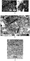
도 6의 (a)는 원료 알루미나 분말 단면의 주사전자현미경 이미지이다. 도 6의 (b)는 (a)의 점선 영역의 확대 이미지이다.
도 7은 알루미나 용사 피막 단면의 투과전자현미경 이미지이다.
도 8은 본 발명의 일 실시형태에 따른 구조체 단면의 투과전자현미경 이미지이다.
도 9는 본 발명의 일 실시형태에 따른 구조체 단면의 투과전자현미경 이미지이다.
도 10은 본 발명의 일 실시형태에 따른 적층체의 단면의 주사전자현미경 이미지이다.
도 11은 본 발명의 일 실시형태에 따른 구조체(1100)의 단면 모델이다.
도 12의 (a)는 본 발명의 일 실시형태에 따른 구조체(1200)의 단면 모델이다. 도 12의 (b)는 기재(1204)에 퇴적되어 형성된 표면 형상이 변형된 미립자(1201)의 상세한 사항을 설명하는 단면 모델이다.
도 13은 본 발명의 일 실시형태에 따른 구조체(1300)의 단면 모델이다.
도 14의 (a)는 본 발명의 일 실시형태에 따른 구조체(1100)의 미립자끼리의 접합 영역을 확대한 것이며, (b)는 본 발명의 일 실시형태에 따른 구조체(1200)의 미립자끼리의 접합 영역을 확대한 것이다.
도 15의 (a)는 단결정 미립자(1010)를 육각형 단결정으로 나타내며, (b)는 결정자(1022)를 가지는 육각형 다결정 미립자(1021)로서 나타내고, (c)는 결정자(1032)를 가지는 육각형 다결정 미립자(1031)가 응집된 응집 분말(1030)을 나타낸다.
도 16의 (a)는 본 발명의 일 실시형태에 따른 구조체를 형성하는 데 사용되는 원료 미립자(1501)를 나타내고, (b)는 본 발명의 일 실시형태에 따른 구조체를 구성하는 변형이 적은 미립자(1101)을 나타내며, (c)는 본 발명의 일 실시형태에 따른 구조체 중 변형이 큰 미립자(1201)를 나타낸다.
도 17은 본 발명의 일 실시형태에 따른 구조체 제조용 장치(2000)의 모식도이다.
도 18은 본 발명의 일 실시형태에 따른 구조체 제조 방법을 설명하는 도면이다.
도 19의 (a)는 종래의 에어로졸 증착법에 의한 원료 미립자(1041)의 충돌 파쇄 변형 단면 모델이며, (b)는 본 발명의 일 실시형태에 따른 제조 방법에 의한 원료 미립자(1041)가 충돌 파쇄 변형되는 단면 모델이다.
도 20의 (a)는 종래 에어로졸 증착법에 의한 입자 간 결합, 입자/기판 간 결합의 단면 모델이며, (b)는 본 발명의 일 실시형태에 따른 제조 방법에 의한 입자 간 결합, 입자/기판 간의 결합 단면 모델이다.
도 21의 (a)는 본 발명의 일 실시예에 따른 미립자의 주사투과전자현미경 이미지를 나타내며, (b)는 전자에너지손실분광법의 맵핑도를 나타낸다.
도 22는 본 발명의 일 실시예에 따른 원료 미립자를 이용한 표면 관찰 이미지를 나타낸다.
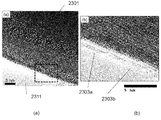
도 23의 (a)는 본 발명의 일 실시예에 따른 출발 원료로 이용한 α-Al2O3를 나타내며, (b)는 미립자를 이용하여 형성한 본 발명에 따른 구조체의 단면 투과전자현미경 이미지를 나타내며, (c)는 비교로서, 출발 원료를 이용하여 에어로졸 증착 방법에 의해 형성한 구조체의 단면 투과전자현미경 이미지를 나타낸다.
도 24의 (a)는 본 발명의 일 실시예에 따른 구조체(1600)의 단면 SEM 이미지를 나타내며, (b)는 본 발명의 일 실시예에 따른 구조체(1700)의 단면 SEM 이미지를 나타낸다.
도 25는 본 발명의 일 실시예에 따른 구조체(1600)의 X선 회절 패턴을 나타낸다.
도 26은 본 발명의 일 실시예에 따른 구조체(1700)의 X선 회절 패턴을 나타낸다.
도 27은 실시예 9 및 실시예 10에서 얻어진 구조체의 X선 회절 패턴을 나타낸다.
도 28은 본 발명의 일 실시예에 따른 원료 미립자의 이용 효율비를 나타낸다.
도 29는 본 발명의 일 실시예에 따른 원료 미립자의 이용 효율비를 나타낸다.
도 30은 본 발명의 일 실시예에 따른 다공질 세라믹을 기재(1804)로 한 구조체(1800)의 주사투과전자현미경에 의한 단면 이미지를 나타내며, (b)는 (a)의 확대도이다.
도 31의 (a)는 본 발명의 일 실시예에 따라 셀로판 테이프를 마스킹에 이용한 결과를 나타내고, (b)는 본 발명의 일 실시예에 따라 폴리이미드 테이프를 마스킹에 이용한 결과를 나타낸다.
도 32의 (a)~(e)는 본 발명의 일 실시예에 따른 구조체를 나타내고, (f)는 본 발명의 일 실시예에 따른 만곡 형상을 가지는 기재를 이용한 구조체를 나타낸다.
도 33은 본 발명의 일 실시예에 따른 세라믹 다공질 기재를 이용한 구조체의 사진이다.
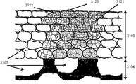
도 34의 (a)는 본 발명의 일 실시예에 따른 구조체의 파단면을 FE-SEM으로 관찰한 이미지이며, (b)는(a)의 기재 계면 근방(3114)을 확대한 관찰 이미지이며, (c)는 (a)의 표층 근방(3113)을 확대한 관찰 이미지이다.
도 35는 본 발명의 일 실시예에 따른 경사 구조체(3100)의 단면 모델이다.
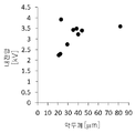
도 36은 아르곤 가스(가스 유량을 20L/min)를 이용하여 제조한 본 발명의 일 실시예에 따른 구조체의 두께와 내전압의 관계를 나타내는 도면이다. 1 is a schematic view of a brittle particulate aggregate according to an embodiment of the present invention.
2 is a schematic view of a brittle particulate aggregate according to an embodiment of the present invention.
FIG. 3 is an explanatory view of the configuration of the ultrafine particle
4 is a mapping diagram of a scanning transmission electron microscope image and an electron energy loss spectroscopy method of a cross section of a structure obtained by an embodiment of the present invention. (a) is annular dark-field imaging by scanning transmission electron microscopy. (b) is a mapping result of α alumina by electron energy loss spectroscopy, (c) is a mapping result of γ alumina by electron energy loss spectroscopy, and (d) is a mapping result of amorphous alumina by electron energy loss spectroscopy. .
5 is an X-ray diffraction result of a raw material particle, a structure (argon gas), and a structure (helium gas) according to an embodiment of the present invention.
6 (a) is a scanning electron microscope image of a raw material alumina powder cross section. 6 (b) is an enlarged image of the dotted area in (a).
7 is a transmission electron microscope image of a cross-section of an alumina thermal spray coating.
8 is a transmission electron microscope image of a cross-section of a structure according to an embodiment of the present invention.
9 is a transmission electron microscope image of a cross-section of a structure according to an embodiment of the present invention.
10 is a scanning electron microscope image of a cross-section of a laminate according to an embodiment of the present invention.
11 is a cross-sectional model of a
12A is a cross-sectional model of a
13 is a cross-sectional model of a structure 1300 according to one embodiment of the present invention.
FIG. 14 (a) is an enlarged bonding area of fine particles of the
15 (a) shows single
Fig. 16A shows raw
17 is a schematic view of an
18 is a view for explaining a method for manufacturing a structure according to an embodiment of the present invention.
FIG. 19 (a) is a cross-sectional model of a collision crushing deformation of raw
Figure 20 (a) is a cross-sectional model of the interparticle bonding, particle / substrate bonding by a conventional aerosol deposition method, (b) is interparticle bonding, particle / substrate bonding by the manufacturing method according to an embodiment of the present invention It is a combined cross-section model.
21 (a) shows a scanning transmission electron microscope image of fine particles according to an embodiment of the present invention, and (b) shows a mapping diagram of an electron energy loss spectroscopy method.
22 shows a surface observation image using raw particulates according to an embodiment of the present invention.
23 (a) shows α-Al 2 O 3 used as a starting material according to an embodiment of the present invention, and (b) shows a cross-sectional transmission electron microscope image of the structure according to the present invention formed using fine particles. (C) is a cross-sectional transmission electron microscope image of a structure formed by an aerosol deposition method using a starting material as a comparison.
24 (a) shows a cross-sectional SEM image of the
25 shows an X-ray diffraction pattern of the
26 shows an X-ray diffraction pattern of the
27 shows the X-ray diffraction patterns of the structures obtained in Examples 9 and 10.
28 shows a utilization efficiency ratio of raw material fine particles according to an embodiment of the present invention.
29 shows a utilization efficiency ratio of raw material fine particles according to an embodiment of the present invention.
30 shows a cross-sectional image of a
31 (a) shows the results of using cellophane tape for masking according to an embodiment of the present invention, and (b) shows the results of using polyimide tape for masking according to an embodiment of the present invention.
32 (a) to (e) show a structure according to an embodiment of the present invention, and (f) shows a structure using a substrate having a curved shape according to an embodiment of the present invention.
33 is a photograph of a structure using a ceramic porous substrate according to an embodiment of the present invention.
34 (a) is an image obtained by FE-SEM of the fracture surface of the structure according to an embodiment of the present invention, (b) is an enlarged observation image 3114 near the substrate interface of (a), (c) is an enlarged observation image in the vicinity of the
35 is a cross-sectional model of an
36 is a view showing the relationship between the thickness of the structure and the withstand voltage according to an embodiment of the present invention manufactured using argon gas (gas flow rate of 20 L / min).
이하, 도면을 참조하여 본 발명에 따른 구조체, 그 적층체, 이들의 제조 방법 및 제조 장치에 대해 설명한다. 또한 본 발명의 구조체, 그 적층체, 이들의 제조 방법 및 제조 장치는 이하 설명하는 실시형태 및 실시예의 기재 내용으로 한정하여 해석되는 것은 아니다. 또한 본 실시형태 및 후술하는 실시예에서 참조하는 도면에서, 동일한 부분 또는 유사한 기능을 가지는 부분에는 동일한 부호를 붙이고 반복 설명은 생략한다.Hereinafter, a structure according to the present invention, a laminate thereof, and a method for manufacturing the same and a manufacturing apparatus will be described with reference to the drawings. In addition, the structure of this invention, its laminated body, their manufacturing method, and manufacturing apparatus are not interpreted as being limited to the contents of the embodiments and examples described below. In addition, in the drawings referred to in the present embodiment and the embodiments described later, the same reference numerals are assigned to the same parts or parts having similar functions, and repeated descriptions are omitted.
본 발명자들은 치밀 구조체 및 다공질 구조체를 연결, 그 중간적인 구조체를 저렴하게 제조할 수 있다면, 그 중간적인 구조체를 통해, 다공질 구조체 상에 치밀 구조체를 적층시킬 수 있을 것이라 예측하였다. 그리고 다공질 구조체 상에 치밀 구조체의 적층이 가능해지면, 세라믹이나 합금 재료 등 취성 재료의 적용 범위를 크게 확대할 수 있어, 산업 발전에 기여할 수 있다고 예측했다. 그래서 이 단차를 평활화할 수 있는 세라믹 구조체 막을 표면에 부여할 수 있다면, 세라믹의 3차원 조형 기술의 실현에도 크게 기여한다.The present inventors predicted that if a dense structure and a porous structure can be connected and the intermediate structure can be manufactured at low cost, the dense structure can be stacked on the porous structure through the intermediate structure. In addition, it was predicted that if a dense structure could be stacked on a porous structure, the range of application of brittle materials such as ceramics and alloy materials could be greatly expanded, contributing to industrial development. Therefore, if a ceramic structure film capable of smoothing this step can be applied to the surface, it greatly contributes to the realization of the three-dimensional molding technology of ceramics.
[취성 재료 가교 구조체 영역][The brittle material cross-linked structure region]
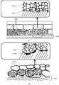
본 발명에서는, 양질의 저렴한 취성 재료의 구조체 및 그 적층체를 제공하기 위해 취성 재료 가교 구조체 영역이라고 이름 붙인, 주상(主相)인 취성 재료 입자보다 자유에너지가 높거나 동일한 상태의 취성 재료 영역에 의해 주상인 취성 재료 입자를 연결한 구조를 취함으로써, 다공질 구조체와 치밀 구조체의 중간 형태인 취성 재료 구조체를 제작할 수 있다. 보다 구체적으로는 복수의 취성 재료 입자를 가지는 취성 재료 입자 집합체를 구비하는 구조체로서, 취성 재료 입자 집합체는, 서로 인접하여 배치되어 있고, 또한 주위에 취성 재료 영역을 구비하는 취성 재료 입자가, 상기 취성 재료 영역에 의해 가교(접속)됨으로써, 상기 취성 재료 입자 간을 결합하여, 상기 취성 재료 입자의 이동을 저지할 수 있기 때문에, 안정된 구조를 형성할 수 있다. 이 취성 재료 영역을 취성 재료 입자에 비해, 자유에너지가 높은 상태로 유지하면서 결합함으로써 가교 구조를 얻는 것을 더욱 쉽게 할 수 있다. 이 결합 후, 결합 상태는 ?칭되어 유지되기 때문에, 결과적으로 취성 재료 가교 구조체 영역의 자유에너지는 취성 재료 입자의 자유에너지에 비해 높거나 같게 된다. 이와 같은 상태로, 예를 들면 비정질을 들 수 있다. 본 발명의 일 실시형태에 따른 구조체를 이용함으로써 상기 과제를 해결할 수 있음을 발견하였다. 본 발명의 일 실시형태에 따른 취성 재료 입자 집합체의 단면을 볼 경우 모식도를 도 1 및 도 2에 나타내었다. 도 1을 참조한다. 복수의 취성 재료 입자(102), 취성 재료 입자(102)의 표면에 존재하는 취성 재료 가교 구조체 영역(101)이 존재하고, 이웃하는 취성 재료 입자(102) 사이가 취성 재료 가교 구조체 영역(101)을 통해 가교(접속)된 형태가 모식적으로 표현되어 있다. 취성 재료 입자(102) 사이에는 공극(103)이 존재하고 있다.In the present invention, in order to provide a structure of a low-quality brittle material of good quality and a laminate thereof, a brittle material region having a higher or equal free energy than the main brittle material particles, called brittle material cross-linked structure region, is provided. By taking the structure in which the brittle material particles which are the main phase are connected, the brittle material structure which is an intermediate form of a porous structure and a dense structure can be produced. More specifically, as a structure including a brittle material particle aggregate having a plurality of brittle material particles, the brittle material particle aggregates are disposed adjacent to each other and the brittle material particles having a brittle material region around them are the brittle. By being crosslinked (connected) by the material region, the brittle material particles can be bound to prevent movement of the brittle material particles, so that a stable structure can be formed. Compared to the brittle material particles, this brittle material region can be made easier to obtain a crosslinked structure by bonding while maintaining a high free energy. After this bonding, the bonding state remains quenched, and as a result, the free energy of the brittle material crosslinked structure region becomes higher or equal to the free energy of the brittle material particles. In this state, for example, amorphous can be mentioned. It has been found that the above problems can be solved by using the structure according to one embodiment of the present invention. 1 and 2 are schematic views showing a cross-section of a brittle material particle aggregate according to an embodiment of the present invention. See FIG. 1. A plurality of
도 2는 가교 구조(104) 부분 및 동일 부분을 확대한 도면이다. 도 2를 참조한다. 취성 재료 입자(105), 취성 재료 입자(106), 비정질 구조를 가지는 영역인 취성 재료 가교 구조체 영역(107)이 존재하고, 취성 재료 입자(105)와 취성 재료 입자(106)가 비정질 구조를 가지는 영역인 취성 재료 가교 구조체 영역(107)에 의해 가교(접속)된 형태가 모식적으로 표현되어 있다. 도 1 및 도 2는 어디까지나 입체적인 가교 상태를 2차원 도면으로 표현한 것이며, 실제로는 도 1의 지면 뒤쪽이나 도 2의 지면 뒤쪽에는 취성 재료 입자가 더 존재하고, 취성 재료 가교 구조체 영역은 3차원 네트워크 구조를 취한다. 또한 도면 상, 취성 재료 입자의 주위 전체에 취성 재료 가교 구조체 영역이 존재하는 것으로 보이지만, 반드시 그러한 구조에 한정되지 않고, 취성 재료 주위의 적어도 일부에 취성 재료 가교 구조체 영역이 존재하면 충분하다. 취성 재료의 주위 전체에 취성 재료 가교 구조체 영역이 존재하는 것이 바람직하다. 또한 비정질이라 하면 구성 원소가 장기적 주기성을 갖지 않고 비정질 상태인 것을 의미하는데, 금속 원소와 산소, 질소, 탄소, 붕소, 불소 등 비금속 원소와의 비율이, 취성 재료 입자 중의 금속 원소와 산소, 질소, 탄소, 붕소, 불소 등 비금속 원소와의 비율과는 다른 상태로도 정의할 수 있다.2 is an enlarged view of a part of the
이 취성 재료 가교 구조체 영역이 3차원 네트워크 구조를 취함으로써 구조체의 자유도를 증가시킬 수 있다. 또한 취성 재료 영역이 취성 재료 입자의 표면을 균일하게 덮음으로써 취성 재료 입자 간의 밀착력을 향상시킬 수 있다. 이때, 취성 재료 영역의 두께를 100nm 이하로 하면, 취성 재료 가교 구조체 영역에 대해 취성 재료 입자의 비율을 상대적으로 높일 수 있기 때문에 바람직하다.This brittle material cross-linked structure region can increase the degree of freedom of the structure by taking a three-dimensional network structure. In addition, the adhesion between brittle material particles can be improved by uniformly covering the surface of the brittle material particles. At this time, when the thickness of the brittle material region is 100 nm or less, it is preferable because the ratio of brittle material particles to the brittle material crosslinked structure region can be relatively increased.
[취성 재료의 정의][Definition of brittle materials]
본 명세서에서 취성 재료라 함은, 실온 근방에서 구조체를 제작할 때 연성 변형이나 소성 변형을 기대하기 어려운 재료로서, 일반적으로 소성 가공이 어려운 재료를 말한다. 예를 들어 산화물, 질화물, 탄화물, 붕화물, 불화물 등의 세라믹, 유리, 금속간 화합물, 고분자 폴리머 재료 및 실리콘 등의 반도체를 들 수 있다.In the present specification, a brittle material is a material that is unlikely to expect ductile or plastic deformation when fabricating a structure near room temperature, and generally refers to a material that is difficult to perform plastic working. For example, ceramics, such as oxides, nitrides, carbides, borides, fluorides, semiconductors such as glass, intermetallic compounds, polymer polymer materials, and silicon.
[취성 재료 입자의 정의][Definition of brittle material particles]
본 명세서에서 취성 재료 입자라 하면, 상기 취성 재료로부터 구성되는 입자이며, 입도 분포 측정이나 주사전자현미경으로 식별되는 평균 입경 5㎛ 이하의 것을 가리킨다. 평균 입경이 5㎛ 이하이면 구조체의 균일성을 높일 수 있기 때문에 바람직하다. 특히 취성 재료 입자의 크기를 1㎛ 미만으로 하면, 구조의 균일성을 더욱 높일 수 있으며, 또한 봉지 성능, 표면 평활성의 향상이 가능하여 바람직하다. 이때, 주상이 되는 취성 재료 입자는 등방성이 됨으로써, 구조체의 자유도가 증가하고, 3차원 형상 기재 상에의 구조체 형성이 용이하게 된다. 예를 들어 입자의 장경과 단경의 비율이 5 이하인 것이 바람직하다. 또한 본 명세서에서는 취성 재료 입자를 취성 입자 또는 미립자라고 부르는 경우도 있다.When used herein as a brittle material particle, it is a particle composed of the brittle material, and refers to a particle size distribution measurement or an average particle diameter of 5 µm or less identified by a scanning electron microscope. An average particle diameter of 5 µm or less is preferable because the uniformity of the structure can be increased. Particularly, when the size of the brittle material particles is less than 1 µm, the uniformity of the structure can be further increased, and the sealing performance and surface smoothness can be improved, which is preferable. At this time, the brittle material particles serving as the main phase become isotropic, thereby increasing the degree of freedom of the structure and facilitating formation of the structure on the three-dimensionally shaped substrate. For example, it is preferable that the ratio of the long and short diameters of the particles is 5 or less. In addition, in this specification, the brittle material particles are sometimes referred to as brittle particles or fine particles.
[공극][air gap]
또한 본 발명의 일 실시형태에 따른 구조체가 우수한 것은, 취성 재료 가교 구조체 영역 중에 공극을 형성함으로써, 취성 입자 집합 구조체의 실효 탄성계수나 경도를 제어할 수 있다는 점이다. 이때 공극을 적어도 1㎛ 이하로 함으로써 봉지성을 향상시킬 수 있다. 이때 취성 재료 구조체의 비커스경도가 주상 취성 입자의 비커스경도에 대해 0.1 이상으로 함으로써, 구조체로서의 강도를 유지할 수 있으므로 바람직하다. 이때 취성 재료 구조체의 비커스경도가 주상 취성 입자의 비커스경도에 대해 1 미만이 되도록 조정함으로써, 요구되는 사항의 준수(compliance)가 우수한 구조체가 되도록 할 수 있어 바람직하다. 취성 재료 입자의 비커스경도는, 측정이 곤란한 경우에는, 취성 재료 입자를 소결법에 의해 제작한 치밀 벌크 구조체의 비커스경도를 기준으로 할 수도 있다. 비커스경도의 예를 들었는데, 실효 탄성률 등 다른 기계적 물성값, 열전도율, 그리고 임피던스 측정 등 전기적 특성값에 의해서도 유사한 평가가 가능하다. 실효 탄성률에서는, 주상 취성 입자의 탄성률에 대해 1 미만이 되도록 조정함으로써, 요구 사양을 우수하게 충족하는 구조체로 할 수 있어 바람직하다. 이때 0.01 이상으로 함으로써 구조체로서의 강도도 유지할 수 있기 때문에 바람직하다. 본 발명의 일 실시형태에 따른 취성 재료 구조체는 요구 사항을 우수하게 준수할 수 있기 때문에 특히 열충격에 뛰어난 고온 봉지 재료로서 효과적이다.Further, the structure according to one embodiment of the present invention is excellent in that it is possible to control the effective elastic modulus and hardness of the brittle particle aggregate structure by forming voids in the brittle material crosslinked structure region. At this time, the sealing property can be improved by setting the pores to at least 1 µm or less. At this time, the Vickers hardness of the brittle material structure is preferably 0.1 or more with respect to the Vickers hardness of the columnar brittle particles, so that the strength as the structure can be maintained, which is preferable. At this time, by adjusting the Vickers hardness of the brittle material structure to be less than 1 with respect to the Vickers hardness of the columnar brittle particles, it is preferable to be able to achieve a structure having excellent compliance with required requirements. When the Vickers hardness of the brittle material particles is difficult to measure, the Vickers hardness of the dense bulk structure produced by sintering the brittle material particles may be used as a reference. As an example of Vickers hardness, similar evaluation can be performed by other mechanical property values such as effective elastic modulus, thermal conductivity, and electrical property values such as impedance measurement. In the effective modulus of elasticity, it is preferable to adjust the elastic modulus of the columnar brittle particles to be less than 1, so that a structure that satisfies the required specifications can be obtained. At this time, it is preferable because the strength as a structure can be maintained by setting it to 0.01 or more. The brittle material structure according to one embodiment of the present invention is particularly effective as a high-temperature sealing material excellent in thermal shock because it can comply with requirements.
[구성 원소][Composition element]
취성 재료 구조체 영역은 취성 입자와 동일한 원소로 구성되는 것이 안정성의 관점에서 바람직하다. 특히 취성 입자를 구성하는 금속 원소가 두 종류 이상으로 구성되는 경우에는 금속 원소의 조성비가 동일 또는 실질적으로 동일한 것이 안정성 관점에서 바람직하다.It is preferable from the viewpoint of stability that the brittle material structure region is composed of the same elements as the brittle particles. In particular, when the metal elements constituting the brittle particles are composed of two or more types, it is preferable from the viewpoint of stability that the composition ratio of the metal elements is the same or substantially the same.
본 발명의 일 실시형태에 따른 취성 재료 구조체는 취성 재료 가교 구조체 영역을 가지기 때문에, 탄성률 조정이 가능하며, 3차원 형상 표면에의 형성도 용이해서, 금속, 세라믹, 고분자 및 복합 재료 등의 각종 기재에 형성시키기가 용이하다. 이는 기재가 용사 피막 등의 다공질체인 경우에 특히 효과적으로 작용하여 봉지 기능을 유지할 수 있다.Since the brittle material structure according to one embodiment of the present invention has a brittle material crosslinked structure region, it is possible to adjust the modulus of elasticity, and it is also easy to form on a three-dimensional shape surface, and various substrates such as metal, ceramic, polymer and composite materials It is easy to form on. This is particularly effective when the substrate is a porous material such as a thermal spray coating to maintain the sealing function.
또한 중간층으로서 이용하는 것도 가능하고, 다공질 기재 상에 본 발명의 일 실시형태에 따른 취성 재료 구조체를 형성하고, 그 위에 치밀 구조체를 제작함으로써, 추가적인 봉지 기능 향상을 도모할 수 있다. 이때 충돌 에너지의 조력을 더함으로써, 취성 재료 입자를 기재에 대해 수직으로 편평한 형상으로 할 수 있어, 봉지성의 추가적인 향상을 기대할 수 있다.It is also possible to use it as an intermediate layer, and by forming the brittle material structure according to one embodiment of the present invention on a porous substrate, and producing a dense structure thereon, it is possible to further improve the sealing function. At this time, by adding the assisting force of the collision energy, the brittle material particles can be formed into a flat shape perpendicular to the substrate, so that further improvement in sealing properties can be expected.
[구조체 제조 방법][Structure manufacturing method]
본 발명의 일 실시형태에 따른 구조체는, 예를 들면 표면을 플라즈마에 의해 활성화시킨 취성 재료 입자를 적층시킴으로써 제조할 수 있다. 이때, 보다 구체적으로는, 주상인 수 ㎛ 이하의 취성 재료 입자 주위에 플라즈마나 레이저 등의 고에너지를 균일하게 조사한다. 취성 재료 입자의 중심을 상변태 온도 이하로 억제하면서 표면을 활성화시킨 상태로 함으로써, 취성 재료 입자의 표면에 에너지 조사에 의해 활성화도가 높은 상이 균일하게 석출한다. 이때 플라즈마 및 레이저 조사장(照射場)은 유체로서의 성질을 잔류시킨 상태로 하기 때문에, 취성 재료 입자의 가속원으로 할 수 있고, 이 활성화도가 높은 입자를 충돌시켜 적층함으로써, 활성화도가 높은 취성 재료 영역이 서로 반응하여 3차원 네트워크를 형성한다. 이때 주상인 취성 재료 입자는 원료 상태를 유지하고 있으며, 초기에 조합된 결정상을 유지할 수 있다. 또한 전자 온도가 높은 플라즈마에 추가로 열유체로서의 성질도 부여한 상태에서 취성 재료 입자를 통과시킴으로써, 중심부를 상변태 온도 이하로 억제하면서, 표면을 활성화시킨 상태에서 충돌시키는 것이 용이해지므로 바람직하다.The structure according to one embodiment of the present invention can be produced, for example, by laminating a brittle material particle whose surface has been activated by plasma. At this time, more specifically, high energy, such as plasma or laser, is uniformly irradiated around the brittle material particles of several µm or less as the main phase. By suppressing the center of the brittle material particles below the phase transformation temperature, the surface is activated, whereby a highly active phase is uniformly deposited on the surface of the brittle material particles by energy irradiation. At this time, since the plasma and the laser irradiation field remain in the state of retaining the properties as a fluid, it can be used as an acceleration source for brittle material particles, and by bridging and stacking the particles with high activation, the brittleness with high activation is high. The material regions react with each other to form a three-dimensional network. At this time, the brittle material particles, which are the main phase, maintain the raw material state, and can maintain the initially combined crystal phase. In addition, it is preferable to pass the brittle material particles in a state in which the properties as thermal fluid are also imparted to the plasma having a high electron temperature, so that it is easy to collide with the surface activated while suppressing the center portion below the phase transformation temperature.
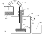
도 3은 본 발명의 일 실시형태에 따른 취성 재료 구조체의 형성에 이용한 장치의 개략도이다. 본 장치는 성막 챔버(111)를 가진다. 성막 챔버(111)에는 노즐(112)이 설치되어 있다. 노즐(112)에는 고주파 플라즈마를 발생시키기 위해 전류를 유동시키는 코일(113)이 설치되어 있다. 또한 성막 챔버(111)에는 진공 배관(114) 및 진공 펌프(115)가 접속되어 있다. 노즐(112)은 성막 챔버(111)의 외부에 설치되는 에어로졸 발생장치(116)에 초미립자를 반송하는 반송관(117)을 통해 접속되어 있다. 또한 성막 챔버(111)에는 압력을 측정하기 위한 압력계(118)가 설치되어 있다. 진공 배관(114) 및 진공 펌프(115)에 의해 성막 챔버(111) 내를 감압하고, 성막 시의 압력을 압력계(118)에 의해 읽는다. 성막 챔버(111) 내에는 기재(119)가 설치된다. 기재(119)는 노즐(112)에 대해 고정되거나 위치가 변할 수 있다.3 is a schematic view of an apparatus used for forming a brittle material structure according to an embodiment of the present invention. The device has a
이와 같이 구성된 장치를 사용하여 취성 재료 구조체는 다음과 같은 작업을 통해 형성된다. 진공 펌프(115)를 운전하여, 진공 배관(114)을 통해 증착 챔버(111) 내를 감압 상태로 둔다. 이 상태에서 노즐(112)에 헬륨이나 아르곤 등의 가스를 유동시키고 코일(113)에 전류를 흐르게 함으로써, 노즐(112) 내에 유도 결합형 고주파 플라즈마를 발생시킨다. 또한 에어로졸 발생장치(116)를 운전하여, 원료인 취성 재료 입자(120)인 초미립자를 에어로졸화시켜 초미립자 에어로졸을 발생시킨다. 생성된 초미립자 에어로졸은 반송관(117)을 통해 노즐(112)로 전달된다. 반송된 초미립자 에어로졸은, 노즐(112)의 유도 결합형 고주파 플라즈마에 의해, 각 입자의 표면이 활성화되어 표면 활성화 초미립자(121)가 된다. 표면 활성화 초미립자(121)는, 노즐(112)을 통해 감압된 성막 챔버 내로 도입되어 기재(119) 상에 분사된다. 분사된 표면 활성화 초미립자(121)는 기재(119) 상에 퇴적되어, 초미립자의 표면 활성화면끼리 강하게 결합하여, 표면 활성 취성 구조체의 3차원 네트워크를 형성한다. 이때 원래의 표면 활성부는 각 초미립자 표면에 존재하고 있기 때문에, 표면 활성 3차원 네트워크 중에 취성 재료 입자를 가지는 3차원 네트워크 표면 활성 구조체가 된다. 또한 표면 활성 3차원 네트워크 중에는, 공극도 생성되며, 취성 재료 입자의 충전 정도에 따라 이 공극량을 제어할 수 있다. 이때 공극이 표면 활성 물질로 충전된 구조도 가질 수 있다. 플라즈마 가스로서 헬륨을 사용함으로써, 아르곤 가스를 사용하는 경우에 비해 더 충전도가 높은 치밀한 구조체를 형성할 수 있다.Using the device thus constructed, the brittle material structure is formed through the following operations. The
여기서는 입자의 활성원으로 유도 결합형 고주파 플라즈마를 이용했지만, 직류 플라즈마를 이용해도 무관하다. 또한 용량 결합형 고주파 플라즈마를 이용하여도 무관하다. 플라즈마의 전자 온도를 높은 상태로 유지하는 한편, 플라즈마 가스가 유체 또는 열유체로서의 성질도 잔류시켜, 취성 재료 입자의 가속 또는 가열가속원이 되도록 하는 것이 중요하다.Here, an inductively coupled high-frequency plasma was used as the active source of the particles, but a DC plasma may be used. It is also irrelevant to use a capacitively coupled high frequency plasma. It is important to keep the electron temperature of the plasma high while maintaining the properties of the plasma gas as a fluid or a thermal fluid so that it becomes an acceleration or heating acceleration source for brittle material particles.
취성 재료 미립자의 투입 형태로는 에어로졸화 방식의 예를 소개했지만, 미립자를 용매 중에 분산시킨 현탁액 형식도 전혀 상관이 없다.An example of an aerosolization method has been introduced as an input form of the brittle material fine particles, but the suspension type in which the fine particles are dispersed in a solvent is also irrelevant.
본 발명의 일 실시형태에 따른 취성 재료 구조체 영역을 형성할 때 충돌 에너지의 조력을 더함으로써, 상온 충격 고화 현상의 협력을 더할 수 있어, 보다 치밀한 구조체로 할 수도 있다. 이때 취성 재료 입자는 기재에 대해 수직으로 편평한 형상이 된다. 이 취성 재료 입자의 변형은 고상 입자의 변형이기 때문에, 용사법에서 나타나는 것 같은 용융 액적의 편평함에 비하면 편평함의 종횡비(aspect ratio)가 작다. 취성 재료 입자가 변형될 때, 결정자 크기의 미세화가 수반된다. 또한 본 발명의 일 실시형태에 따른 취성 재료 구조체 영역을 형성할 때, 충돌 에너지가 조력하는 양을 상대적으로 증대시켜감으로써, 공극량이 상방을 향해 감소된 경사 구조체를 형성할 수도 있다.When forming the brittle material structure region according to one embodiment of the present invention, by adding the assistance of the collision energy, the cooperation of the room temperature impact solidification phenomenon can be added, and a more compact structure can also be obtained. At this time, the brittle material particles have a flat shape perpendicular to the substrate. Since the deformation of the brittle material particles is a deformation of the solid particles, the aspect ratio of the flatness is small compared to the flatness of the molten droplets as seen in the thermal spraying method. When the brittle material particles are deformed, crystallization-sized micronization is involved. In addition, when forming the brittle material structure region according to one embodiment of the present invention, it is also possible to form an inclined structure in which the amount of voids is reduced upward by increasing the amount assisted by the collision energy relatively.
본 발명의 일 실시형태에 따른 취성 재료 구조체 영역의 형성 시 열에너지의 조력을 추가함으로써, 반용융 상태의 협력을 더할 수 있어, 3차원 형성의 자유도를 증가시킬 수 있다.By adding the help of thermal energy when forming the brittle material structure region according to an embodiment of the present invention, cooperation in a semi-melted state can be added, thereby increasing the degree of freedom of three-dimensional formation.
한편, 전술한 종래 방법의 문제점을 감안하여, 구조체에 사용되는 미립자나 기재에 열 이력을 부여하지 않는 범위에서, 미립자나 기재의 극표층(極表層)만을 미립자끼리나 미립자와 기재 사이의 접합을 용이한 상태로 하고, 미립자끼리나 미립자와 기재를 접합하여, 접합 영역에 대해 압축 응력을 주면, 종래 용사법의 과제인 원료 미립자의 결정 구조를 유지하는 치밀한 구조체를 형성할 수 있다. 또한 기존 에어로졸 증착법의 과제인 원료 미립자의 고이용효율화나 구조체 형성의 고속화도 가능하다. 또한 전술한 바와 같이 미립자끼리나 미립자와 기재 사이를 접합하면, 기재의 재질이나 형상에 얽매이지 않고 미립자 사이뿐만 아니라, 미립자와 기재 사이에도 양호한 피복성 및 밀착성이 확보된다. 그리고 기재의 재질이나 형상에 구애 없이 치밀한 구조체를 형성함으로써, 세라믹이나 합금 재료 등 취성 재료의 적용 범위를 크게 확대할 수 있어, 산업 발전에 기여할 수 있다.On the other hand, in view of the problems of the above-described conventional method, only the polar surface layer of the fine particles or the substrate is bonded between the fine particles or the fine particles and the substrate in a range in which no thermal history is applied to the fine particles or the substrate used in the structure. If it is made into an easy state, and the fine particles are bonded to each other or the substrate and the compressive stress is applied to the joining region, a dense structure that maintains the crystal structure of the raw material fine particles, which is a problem of the conventional thermal spraying method, can be formed. In addition, it is possible to increase the efficiency of high-efficiency use of raw material particles, which is the subject of the existing aerosol deposition method, and to speed up the formation of structures. In addition, when the fine particles are bonded to each other or between the fine particles and the substrate as described above, it is not bound by the material or shape of the substrate and ensures good coatability and adhesion not only between the fine particles but also between the fine particles and the substrate. In addition, by forming a dense structure without regard to the material or shape of the base material, the application range of brittle materials such as ceramics and alloy materials can be greatly expanded, contributing to industrial development.
본 발명의 일 실시형태에서, 상술한 과제를 해결하기 위해, 원료 미립자나 기재에 대해 열 및 물리적 손상을 주지 않는, 예를 들면 원료 미립자를 용해시키지 않는 범위 내에서, 미립자 사이나 미립자와 기재 사이의 접합을 촉진하는, 미립자 및 기재의 극표층에 활성 영역을 생성하는 것을 발견하였다. 더욱이, 생성하는 활성 영역을 통한 접합 영역에 대해, 압축 응력을 부여함으로써, 압축 잔류 응력을 가지는 구조체가 형성될 수 있음을 발견하였다. 바람직하게는, 접합 영역에 대해, 균일하게 압축 응력을 부여함으로써, 원료 미립자의 결정 구조를 유지한 등방성 구조를 나타내는, 균일하고 균질하며 치밀한, 압축 잔류 응력을 갖춘 구조체가 형성 가능하다.In one embodiment of the present invention, in order to solve the above-mentioned problem, within the range that does not dissolve the raw material fine particles or heat, physical damage to the raw material fine particles or the substrate, for example, between the fine particles or between the fine particles and the substrate It has been found to create active regions in the polar surface layer of particulates and substrates, which promotes the bonding of. Moreover, it has been found that by applying compressive stress to the bonding region through the active region to be produced, a structure having compressive residual stress can be formed. Preferably, a structure having a uniform, homogeneous and dense, compressive residual stress that exhibits an isotropic structure that maintains the crystal structure of the raw material fine particles can be formed by uniformly applying compressive stress to the bonding region.
보다 구체적으로는, 전술한 미립자나 기재의 극표층에 이온, 원자, 분자빔이나 저온 플라즈마 등의 고에너지 원자, 분자인 고속의 고에너지빔을 조사하여, 원료 미립자 및 기재를 완전 용해 또는 분해하지 않고, 미립자나 기재 표면에 부착된 물분자 등에 의한 오염층이나 산화물층이 제거된 표면 활성 영역을 형성한다. 동시에 미립자 사이 및 미립자와 기재의 충돌 압력에 의해, 원료 미립자 파쇄에 의한 결정자 크기의 미세화를 촉진하고, 파쇄 입자에 의한 표면 활성 영역을 형성한다. 그리고 미세화된 원료 미립자를 포함하는 표면 활성 영역을 가지는 미립자를 물질 유동에 의해 접합시켜, 구조체에 있어 피복부의 치밀화가 실현된다. More specifically, by irradiating a high energy beam of high energy atoms and molecules, such as ions, atoms, molecular beams or low temperature plasmas, on the polar surface layer of the aforementioned fine particles or substrate, the raw material particles and the substrate are not completely dissolved or decomposed. Instead, a surface active region in which a contaminant layer or an oxide layer due to water particles or the like attached to the surface of the substrate is removed is formed. At the same time, by the collision pressure between the fine particles and the fine particles and the substrate, micronization of the crystallite size by crushing the raw material fine particles is promoted, and a surface active region by the crushed particles is formed. Then, the fine particles having a surface active region containing the fine-grained raw material fine particles are bonded by mass flow, thereby realizing densification of the covering portion in the structure.
원료 미립자의 결정 구조를 거의 유지하여, 접합하기 쉬운 상태로 되어 있는 미립자 표면과 기재 표면은, 충돌 압력에 의해 각각이 인접함으로써, 표면 활성 영역을 통해 접합된 접합 영역을 입자 사이 및 미립자와 기재 사이에 형성한다. 게다가 접합 영역에는, 미립자나 기재 극표층을 전자적으로 여기시키는 등으로 하여 결정 구조가 혼란스럽게 되어 있는 상태 또는 미립자 표면이 용융된 활성 영역을 포함하고 있고, 활성 영역을 포함하는 접합 영역의 두께는 30nm 이하가 된다. 또한 미립자끼리의 접합부에 활성 영역이 형성된 결정 입자 간 결합의 기계적 강도는 저하되지만, 결정 입자 자체는 충돌 압력에 의해 미세화됨으로써 결정립에 다수의 전위가 도입되어, 구조체에 높은 압축 잔류 응력을 형성할 수 있으며, 그로 인해 구조체 전체로는 높은 기계적 강도를 얻을 수 있다.The particle surface and the substrate surface, which maintain the crystal structure of the raw material fine particles and are easy to bond, are adjacent to each other by collision pressure, so that the bonding regions bonded through the surface active region are between particles and between the fine particles and the substrate. To form. In addition, the bonding region includes an active region in which the crystal structure is confused or the surface of the microparticles is melted by electronically exciting the fine particles or the substrate polar surface layer, and the thickness of the bonding region including the active region is 30 nm. It becomes the following. In addition, although the mechanical strength of the bonding between the crystal grains in which the active region is formed at the joints between the fine particles decreases, the crystal grains themselves are refined by the collision pressure, thereby introducing a large number of dislocations into the grains, which can form a high compressive residual stress in the structure. Thereby, high mechanical strength can be obtained as a whole of the structure.
미립자 사이나 미립자와 기재 사이의 접합 영역에는, 원료 미립자나 기재를 구성하는 원소가 포함되어 있고, 접합 영역을 형성하는 원료 미립자의 종류나 기재의 종류, 미립자와 기재의 조합에 의해, 예를 들면 공유 결합이나 이온 결합 등의 화학 결합에 의해 미립자끼리나 미립자와 기재를 접합한다. 원료 미립자의 극표층이나 기재의 극표층에만 전술한 활성 영역을 부여하기 때문에, 결과적으로 전술한 접합 영역을 가지는 원료 미립자의 결정 구조를 유지한 구조체를 형성할 수 있다.The bonding region between the fine particles or between the fine particles and the substrate contains the raw material fine particles and the elements constituting the substrate, and the combination of the fine particle and the type of the raw material fine particles forming the bonding region and the combination of the fine particles and the substrate, for example The fine particles or the fine particles are bonded to the substrate by chemical bonding such as covalent bonding or ionic bonding. Since the above-mentioned active region is provided only to the polar surface layer of the raw material fine particles or the polar surface layer of the base material, as a result, a structure maintaining the crystal structure of the raw material fine particles having the above-described bonding region can be formed.
여기서, 본 명세서에서 취성 재료라 하면, 실온 근방에서 구조체를 제작할 때 연성 변형이나 소성 변형을 기대하기 어려운 재료로서, 일반적으로 소성 가공이 어려운 재료를 말한다. 예를 들어 산화물, 질화물, 탄화물, 붕소화물 등의 세라믹, 유리, 금속간 화합물, 실리콘 등의 반도체를 들 수 있다. 본 명세서에서 기재라 하면 취성 재료, 금속, 고분자 및 이들 재료의 다공질 재료이다. 또한 본 명세서에서 원료 미립자라 하면, 세라믹 미립자 등의 취성 재료 입자뿐만 아니라, 금속 미립자, 고분자 폴리머 미립자 등에도 적용 가능하다.Here, in the present specification, the brittle material is a material that is unlikely to expect ductile or plastic deformation when fabricating a structure near room temperature, and generally refers to a material that is difficult to perform plastic working. For example, ceramics, such as oxides, nitrides, carbides, borides, semiconductors, glass, intermetallic compounds, and silicon, are mentioned. The base material in this specification is a brittle material, a metal, a polymer, and a porous material of these materials. In addition, in this specification, the raw material fine particles are applicable not only to brittle material particles such as ceramic fine particles, but also to metal fine particles, polymer polymer fine particles, and the like.
얻어진 구조체는, 미립자에 대해 충돌 압력에 의한 결정자의 미세화는 일어나도, 열에 의한 결정자의 비대화는 일어날 수 없기 때문에, 변형 후 미립자의 체적은, 출발 원료인 미립자의 체적을 가지고 있다. 변형 후 미립자의 결정자 크기는 1nm에서 300nm의 결정자를 가지고 있다. 구조체에 압축 잔류 응력을 갖게 함으로써 미립자의 접합 영역이 강화되어, 구조체의 경도 범위는 비커스경도로 표현하면 Hv200 이상 Hv1500 이하이다.The obtained structure has a volume of fine particles as a starting material, since the crystallization by heat cannot be enlarged, although crystallization of crystallites by collision pressure does not occur. After deformation, the crystallite size of the fine particles has crystallites from 1 nm to 300 nm. By giving the structure a compressive residual stress, the bonding region of the fine particles is strengthened, and the hardness range of the structure is expressed in Vickers hardness to Hv200 or more and Hv1500 or less.
여기에서 구조체를 형성하는 데 필요한 에너지 총합을, 플라즈마 등에 의해 전자적 및/또는 열적으로 노출되어 생성되는 미립자의 극표층에 부여된 활성 영역이 가지는 표면 활성화 에너지와, 전술한 미립자의 운동 에너지로 정의한다. 전술한 미립자의 표면 활성화 에너지라 하면, 비정질상을 포함하는 활성 영역을 통해 미립자 사이의 접합이나 그 접합을 촉진하는 것 등에 이용되는 에너지이다. 전술한 미립자의 운동 에너지라 하면, 미립자의 충돌 파쇄(결정 미세화)에 의해 결정립 내부에 전위가 도입되어, 미립자 사이의 접합에 대해 압축 잔류 응력을 부여함으로써 미립자 사이 및 미립자와 기재의 접합 강화를 도모하는 에너지이다. 본 발명에 따라 압축 잔류 응력을 부여한 구조체에서, 구조체의 내부 응력을 분자로 하고 구조체 피복부의 기계적 강도(비커스경도)를 분모로 하여 계산된 수치를, 미립자의 접합력을 나타내는 수치로 정의한다. 전술한 피복부의 기계적 강도나 압축 응력은 구조체를 형성하는 기재에 의해 영향을 받는데, 전술하는 분자·분모 모두 그 영향을 포함하기 때문에, 정의된 값은 미립자의 접합력을 반영한 수치이다 . 본 발명의 일 실시형태에 따른 구조체에서 0.02<내부 압축응력/비커스경도이며, 바람직하게는 0.02<내부 응력/비커스경도<0.5이다. 이때 비커스경도는, 예를 들어 MPa 환산으로 구할 수 있다. 또한 압축 잔류 응력은, 예를 들어 X선 회절 피크 시프트로부터 추정할 수 있다.Here, the sum of the energy required to form the structure is defined as the surface activation energy of the active region provided to the polar surface layer of the fine particles generated by electronically and / or thermally exposed by plasma or the like, and the kinetic energy of the fine particles described above. . The surface activation energy of the above-mentioned fine particles is energy used for bonding between the fine particles through the active region containing the amorphous phase and promoting the bonding. Speaking of the kinetic energy of the fine particles described above, dislocations are introduced into the crystal grains by collision crushing (fine crystallization) of the fine particles, thereby providing a compressive residual stress to the bonds between the fine particles, thereby strengthening the bonding between the fine particles and the substrate. Energy. In the structure to which the compressive residual stress is applied according to the present invention, the numerical value calculated by using the internal stress of the structure as a molecule and the mechanical strength (Vickers hardness) of the structure coating portion as a denominator is defined as a value representing the bonding strength of the fine particles. The mechanical strength or compressive stress of the above-mentioned coating part is influenced by the substrate forming the structure, and since the above-mentioned molecules and denominators include the influence, the defined value is a value reflecting the bonding force of the fine particles. In the structure according to an embodiment of the present invention, 0.02 <internal compressive stress / Vickers hardness, preferably 0.02 <internal stress / Vickers hardness <0.5. At this time, the Vickers hardness can be obtained, for example, in terms of MPa. In addition, the compressive residual stress can be estimated, for example, from an X-ray diffraction peak shift.
도 11은 본 발명의 일 실시형태에 따른 구조체(1100)의 단면 모델이다. 구조체(1100)는, 기재(1104)와 기재(1104)에 퇴적되어 형성된 표면 형상이 변형된 미립자(1101)를 구비하며, 미립자(1101)는, 비정질상을 포함하는 활성 영역(1103)을 구비한 접합 영역을 두고 인접하는 미립자(1101)와 결합한다. 구조체(1100)는, 미립자(1101)의 표면 활성화 에너지와 미립자(1101)의 운동 에너지 비율에서, 예를 들면 운동 에너지를 많이 이용한 경우에 얻어진다.11 is a cross-sectional model of a
구조체(1100)를 형성하는 데 필요한 에너지 중 운동 에너지의 비율을 높게 함으로써, 원료 미립자의 미세화를 동반한 물질 유동이 진행되어 치밀한 구조체가 얻어진다. 또한 운동 에너지의 비율을 높임으로써 얻어지는 구조체(1100)는, 미립자(1101)의 충돌 파쇄(결정 미세화)에 의해 결정립 내부에 전위를 도입하고, 미립자(1101) 사이의 접합에 대해 높은 압축 잔류 응력을 부여함으로써, 미립자(1101) 사이의 접합이 강화된 고밀도의 구조체(1100)가 얻어진다. 출발 원료가 되는 미립자에 의해, 구조체(1100) 중에 포함되는 미립자(1101)는 충돌 파쇄(결정 미세화)를 일으켜, 미립자(1101)의 내부에 결정자(1102)를 생성시킨다. 즉 미립자(1101)는 복수의 결정자(1102)로 구성된다. 또한 미립자(1101)는 높은 압축 응력에 의해 변형도 수반한다.By increasing the ratio of kinetic energy among the energy required to form the
도 12(a)는 본 발명의 일 실시형태에 따른 구조체(1200)의 단면 모델이다. 도 12(b)는 기재(1204) 상에 퇴적되어 형성된 표면 형상이 변형된 미립자(1201)를 상세히 설명하는 단면 모델이다. 구조체(1200)는, 기재(1204)와, 기재(1204) 상에 퇴적되어 형성된 표면 형상이 변형된 미립자(1201)를 구비하며, 미립자(1201)는 비정질상을 포함하는 활성 영역(1203)을 구비한 접합 영역을 두고 인접하는 미립자(1201)와 결합한다. 미립자(1201)는 기재(1204) 상에 퇴적되어 피복부(1205)를 구성한다. 구조체(1200)는, 미립자(1201)의 표면 활성화 에너지와 미립자(1201)의 운동 에너지 비율에서 운동 에너지를 많이 이용하고, 또한 원료 미립자에 입도 분포를 갖게 함으로써, 얻어지는 구조체의 밀도를 높인 경우에 얻어진다. 12A is a cross-sectional model of a
도 12(a) 및 도 12(b)에서, 변형 후 미립자(1201)의 결정자는 1nm 이상 300nm 이하의 크기를 가지고 있다. 변형 후 미립자(1201)의 체적은 출발 원료 미립자의 체적을 가지고 있다. 미립자 표층에는 비정질상을 포함하는 활성 영역(1203)을 구비하고 있다. 얻어지는 구조체(1200)가 높은 압축 잔류 응력을 가질 때, 구조체(1200) 중의 미립자(1201) 미세화되고, 또한 미립자(1201)는 변형을 수반하는 경우가 있다. 구조체를 형성하는 기재(1204)는 미립자(1201) 표층의 비정질상을 포함하는 활성 영역(1203)과의 접합 영역을 가진다. 미립자(1201)의 접합 영역에는 미세화된 결정자(1206)가 존재한다. 기재(1204)는, 예를 들어 취성 재료, 금속, 고분자 및 재료의 다공질 물질이다. 비정질상을 포함하는 접합 영역에서는, 계면을 형성하는 원료 미립자나 기재(1204) 재료의 조합에 의해, 예를 들면 공유 결합이나 이온 결합 등의 화학 결합에 의해 미립자(1201)끼리나 미립자(1201)와 기재(1204)를 접합한 계면으로 된다. 전술한 결합 등에 의해, 미립자(1201) 사이나 미립자(1201)와 기재(1204) 사이의 접합을 강화하고, 또한 각각의 접합 영역에 부여된 압축 응력은 접합 영역의 기계적 강도 강화를 도모하고 있다.12 (a) and 12 (b), the crystallites of the
미립자(1201)의 변형은, 예를 들면 도 12(a)에 기재된 하나의 미립자(1201)의 장변(도 12(a)에서 횡방향 화살표)과 단변(도 12(a)에서 수직 방향 화살표)에 대해, 단변을 분자, 장변을 분모로 하여 나누어 산출하는 경우, 미립자(1201)의 변형을 나타내는 수치는 0.1에서 0.99 범위이며, 변형된 미립자(1201)의 체적은 전술한 바와 같이 변형 전 출발 원료의 체적을 가지고 있다.The deformation of the
도 13은 본 발명의 일 실시형태에 따른 구조체(1300)의 단면 모델이다. 구조체(1300)는, 기재(1304)와, 기재(1304) 상에 퇴적되어 형성된 표면 형상이 변형된 미립자(1301)를 구비하며, 미립자(1301)는, 비정질상을 포함하는 활성 영역(1303)을 가지는 접합 영역을 두고 인접하는 미립자(1301)와 결합한다. 미립자(1301)는 결정자(1302)를 가지고 있다. 또한 구조체(1300)는, 비정질상을 포함하는 활성 영역(1303)을 가지는 접합 영역을 두고 인접하는 미립자(1301)와 결합하지 않는 공극(1307)을 가진다. 구조체(1300)는, 미립자(1301)의 표면 활성화 에너지와 미립자의 운동 에너지 비율에 있어서, 예를 들면 운동 에너지를 적게 사용하는 경우에 얻어진다. 구조체(1300)를 형성하는 데 필요한 에너지 중, 운동 에너지의 비율을 낮게 함으로써, 얻어지는 구조체는, 입자의 충돌 파쇄(결정 미세화) 정도가 낮아, 결정립 내부로의 전위는 적게 되어, 미립자 사이의 접합에 대해 미치는 압축 잔류 응력은 낮게 된다. 한편 미립자의 표면 활성화 에너지에 의해 미립자 사이의 접합이 강화되어 있어 저밀도 구조체가 얻어진다. 이 경우 구조체(1300)에서 미립자의 미세화는 구조체(1100)에 비해 적고, 또한 입자의 변형도 구조체(1100)에 비해 적고, 거의 변형이 없다. 13 is a cross-sectional model of a structure 1300 according to one embodiment of the present invention. The structure 1300 includes a
도 14(a)는 본 발명의 일 실시형태에 따른 구조체(1100)에서 미립자끼리의 접합 영역을 확대하여 나타낸다. 도 14(b)는 본 발명의 일 실시형태에 따른 구조체(1200)에 대한 미립자끼리의 접합 영역을 확대해서 나타낸다. 도 14(a) 및 도 14(b)에 나타난 구조체 중 미립자끼리의 접합 영역은, 미립자의 극표층 각각의 활성 영역이 접합된 영역으로서, 도 14(a) 및 도 14(b )에서 점선으로 나타냈으며, 또한 고온의 전자나 이온에 의해, 원자(도 14(a) 및 도 14(b)의 테두리 중에 원으로 나타난)끼리의 결합이 절단되거나 신축되어 결정 구조가 흐트러진 상태인, 미립자 극표층의 각 비정질상을 포함하는 활성 영역이 접합된 접합 영역을 확대하여 표시하였다. 구조체(1100)의 접합 영역에서, 구조체(1100) 중의 미립자(1101a) 및 미립자(1101b)는 도 14(a)에 화살표로 표시한 압축 응력을 가한다. 구조체(1200)의 접합 영역에 대하여, 구조체(1200) 중의 미립자(1201a) 및 미립자(1201b)는 도 14(b)의 점선의 화살표로 표시된 압축 응력을 충돌 분쇄에 의해 미세화된 미립자에 의해 접합 영역에 부여한다. 또한 이때 구조체(1200) 중의 미립자(1201a) 및 미립자(1201b)는 압축 응력에 의해 변형되기 때문에, 구조체(1100)의 미립자(1101a)나 미립자(1101b)보다도 구조체(1200) 중의 미립자(1201a)나 미립자(1201b)는 변형되어 있다. 또한 화살표로 표시된 압축 응력은 구조체(1200)보다도 구조체(1100) 쪽이 크고, 예를 들면 구조체(1100)의 높은 압축 잔류 응력을 가지는 치밀한 구조체 중의 미립자(1101)나 미립자(1101) 사이의 접합 영역은, 구조체(1200)처럼 미립자(1201)의 충돌 파쇄(결정 미세화)에 의해 결정립 내부에 전위가 도입되어, 미립자 사이의 접합에 높은 압축 잔류 응력을 부여하여, 미립자(1101) 사이의 접합이 강화되어 있다.14 (a) is an enlarged view showing a bonding region between fine particles in the
여기서 도 15을 참조한다. 도 15는 본 발명에 따른 구조체의 제조 방법에 의해 형성되는 비정질상을 포함하는 활성 영역을 구비하는 미립자의 단면 모델이다. 도 15(a)는 단결정 미립자(1010)를 육각형의 단결정으로 나타내며, 도 15(b)는 결정자(1022)를 구비하는 육각형 다결정 미립자(1021)로서 나타내며, 도 15(c)는 결정자(1032)를 구비하는 육각형 다결정 미립자(1031)가 응집된 응집 분말(1030)을 나타낸다.See FIG. 15 here. 15 is a cross-sectional model of microparticles having an active region comprising an amorphous phase formed by a method of making a structure according to the invention. 15 (a) shows single
도 16은 본 발명의 일 실시형태에 따른 입자의 구조의 상세를 설명하는 단면 모델이다. 도 16(a)는 본 발명의 일 실시형태에 따른 구조체를 형성하는 데 사용되는 원료 미립자(1501)를 나타내고, 도 16(b)는 본 발명의 일 실시형태에 따른 구조체를 구성하는 변형이 작은 미립자(1101)를 나타내며, 도 16(c)는 본 발명의 일 실시형태에 따른 구조체를 구성하는 변형이 큰 미립자(1201)를 나타낸다. 도 16에 나타난 원료 미립자는 도 15에 나타난 다결정 미립자(1021)뿐만 아니라 단결정 미립자(1010)나, 원료 미립자(1031)를 응집시킨 응집 분말(1030)로 해도 된다. 미립자는 가해진 압축 응력에 의해 변형된다. 도 16(b)의 변형된 미립자(1101)나 도 16(c)의 변형된 미립자(1201)는, 도 16(a)의 원료 미립자(1501)와 동일한 체적을 가지고 있다. 미립자의 변형을 나타내는 지표로서, 미립자의 단변과 장변을, 단변을 분자, 장변을 분모로 하여 나누어 산출하는 경우, 그 수치는 0.1에서 0.99의 범위이다. 도 16(b)나 도 16(c)의 미립자의 표층에는, 플라즈마 등에 의해 생성된 비정질상을 포함하는 활성 영역이 구비된다. 미립자의 변형이 큰 경우에는, 동시에, 미립자 중의 결정자가 충돌 분쇄에 의해 미세화되어, 전위나 왜곡(distortion)이 구비되어, 결정 격자 간격이 좁게 된다. 강한 압축 응력을 준 경우, 도 16(c)의 미립자 표층은, 플라즈마 등에 의해 생성되는 비정질상과, 미립자의 충돌 분쇄에 의해 생성되는 면을 구비하는 표층(1211)으로 된다. 예를 들면 강한 압축 응력에 의해, 도 16(c)의 미립자 표층의 플라즈마 등에 의해 생성되는 비정질상 일부는 균열되어, 미립자 중 결정자가 표층에 나타나 있는 미립자 표층(1212)으로 된다. 본 발명의 구조체는 도 16(b)나 도 16(c)의 특징을 갖춘 미립자, 또한 미립자가 혼재하는 구조체가 형성된다.16 is a cross-sectional model for explaining details of a structure of particles according to an embodiment of the present invention. Fig. 16 (a) shows raw
상술한 실시형태에 따른 구조체를 형성하는 출발 원료를 단결정 미립자(1010)로 하는 경우, 본 발명에 따른 구조체의 제조 방법에 의해, 그 표면에 활성 영역(1013)을 형성할 수 있는데, 단결정 미립자(1010)의 미세화는 다결정 미립자(1021)만큼 진행되지 않고, 접합 영역에 부여되는 압축 응력이 작은 등의 이유에 의해, 다결정 미립자(1021)를 출발 원료로 하는 경우보다 단결정 미립자(1010)를 출발 원료로 하는 구조체의 기계적 강도가 낮다. 또한 본 발명의 실시형태에 따른 구조체를 형성하는 출발 원료를 다결정 미립자(1031)가 집합된 응집 분말(1030)로 하는 경우, 플라즈마 등에 의해 활성화되는 활성 영역(1033)의 범위는, 응집 분말(1030)의 표면 영역이거나, 미립자의 충돌 분쇄의 일부가 응집 분말(1030)의 파쇄에 이용되거나하는 등의 이유로, 다결정 미립자(1021)를 출발 원료로 하는 경우보다도 응집 분말(1030)을 출발 원료로 하는 구조체의 기계적 강도가 낮다. 출발 원료의 물성 등에 의해서도 영향을 받지만, 구조체의 기계적 강도는, 사용하는 원료 입자가 응집 분말<단결정 미립자<다결정 미립자인 순서로 높아진다. 구조체를 형성할 때 미립자가 응집을 일으키고 있는 경우에는, 미리 에어로졸화된 미립자에 파쇄기 등을 이용하여, 미립자의 응집 상태를 해제하는 방법을 추가함으로써, 다결정 미립자(1021) 표면에 활성 영역(1023)이 형성되어, 얻어지는 구조체의 기계적 강도와 균일성이 더욱 높아진다.When the starting raw material for forming the structure according to the above-described embodiment is single
[구조체 제조 방법][Structure manufacturing method]
상술한 본 발명에 따른 구조체는, 예를 들어 도 17에 나타난 구조체 제조용 장치(2000)를 이용하여 제조할 수 있다. 또한 도 18에 나타난 단계를 따라 본 발명에 따른 구조체 제조 방법의 일 실시형태를 설명한다. 구조체 제조용 장치(2000)는, 예를 들어 에어로졸 발생기(2103), 구조체 제조부(2107) 및 플라즈마 발생용 전원(2108)을 구비한다. 또한 구조체 제조용 장치(2000)는, 원료 미립자 중의 응집 입자나 조립(造粒)에 의해 형성된 2차 입자를 1차 입자 상태로 해제하는 분쇄기(2105)를 갖추는 것이 바람직하다. 에어로졸 발생기(2103)는 가스 반송관(2102)을 통해 반송 및 플라즈마 생성 가스용 봄베(2101)와 접속된다. 에어로졸 발생기(2103)는 에어로졸 반송관(2104)을 통해 분쇄기(2105)에 접속된다. 분쇄기(2105)는 에어로졸 반송관(2106)을 통해 구조체 제조부(2107)에 접속된다.The structure according to the present invention described above can be manufactured, for example, by using the
구조체 제조부(2107)에는 플라즈마 발생장치(2109)가 배치되며, 에어로졸 반송관(2106)이 플라즈마 발생장치(2109)의 일단에 접속된다. 플라즈마 발생장치(2109)의 타단에는 노즐(2110)이 배치된다. 플라즈마 발생장치(2109)로는 예를 들어 유도 코일을 사용할 수 있다. 또한 구조체 제조부(2107)에는, 노즐(2110)에 대향하는 위치에 스테이지(2112)가 배치되며, 스테이지(2112)에는 노즐(2110)에 대향하도록 기재(2111)가 배치된다. 구조체 제조부(2107)에는 구조체 제조부(2107) 내부를 감압, 탈기하는 진공 펌프(2113)가 접속된다. 분쇄기(2105)는 플라즈마 발생장치(2109)의 전단에 배치되는 것이 바람직하다.A
원료 미립자(2301)는 에어로졸 발생기(2103)에서, 예를 들면 반송 및 플라즈마 생성 가스용 봄베(2101)로부터 아르곤이나 헬륨 등의 불활성 가스를 공급하고(S101), 공급되는 가스 종류와 혼합·교반되어 에어로졸화된다(S103). 이어 미립자의 융점 이하 온도 영역에서 플라즈마 발생장치(2109) 내의 에어로졸 반송로나 노즐(2110) 내에 발생하는 비열평형 플라즈마를 이용하여 미립자 표면을 전자적으로 여기시키는 등, 연속적으로 미립자의 극표층에 활성 영역(2130)을 생성한다(S105). 플라즈마 발생장치(2109) 내의 에어로졸 반송로에서, 예를 들어 유도 코일 바로 아래 부근이 가장 에너지가 높은 상태이며, 고에너지 공간이 되는 플라즈마 내부를 미립자가 반송되며, 반송되는 10-2초, 바람직하게는 10-3초로부터 10-5초 사이에 미립자 표층에 활성 영역이 생성된다. 플라즈마 발생장치(2109)의 에어로졸 반송로 내부의, 미립자 표층에 활성 영역을 부여하는 고에너지 공간은, 원료 미립자의 용융점 이하 온도인 것이 바람직하다. 활성 영역(2130)을 부여한 미립자(2302)를 포함하는 에어로졸은 기재(2111)에 분출된다(S107). 기재(2111)에 미립자(2302)가 도달하여, 미립자(2302)의 표면 활성화 에너지와 미립자(2302)의 운동 에너지에 의해, 미립자(2302)끼리 및 미립자(2302)와 기재(2111) 각각의 활성 영역을 통해 접합된 접합 영역을 형성한다. 미립자 표층의 활성 영역 생성에 이용하는 플라즈마는, 기재까지 도달하는 플라즈마 플레임을 가지는데, 기재에 열손상을 주지 않는 것이 바람직하다. 플라즈마에 의해 생성되는 미립자 표층의 활성 영역은, 플라즈마 플레임 중을 비행하여 미립자가 기재에 도달할 때까지 유지되며, 플라즈마에 의해 생성되는 활성 영역 및 미립자의 충돌 파쇄에 의해 생성되는 활성 영역을 통해, 미립자 끼리 및 미립자와 기재가 접합된다. 이에 따라 기재(2111)의 표면에 미립자(2302)가 퇴적하여 피복층(2305)이 형성되어, 구조체(2307)를 제조할 수 있다.The raw
본 발명의 일 실시형태에 따르면, 플라즈마 등에 의해 미립자 표면이나 기재 표면에 부여된 비정질상을 포함하는 활성 영역을 통한 접합 영역에 의한 미립자 사이의 접합과, 미립자의 충돌 파쇄(결정 미세화)에 의해 결정립 내에 전위를 도입하여, 미립자 사이의 접합에 대해 높은 압축 응력을 부여하여 미립자 사이의 접합의 강화를 도모함에 따라, 구조체의 기계적 강도는 향상된다. 본 발명의 일 실시형태에 따르면, 1차 입자의 충돌 파쇄 효과와 플라즈마의 열적 효과에 의해, 1차 입자 표면에 활성 영역을 형성한다. 또한 본 발명의 일 실시형태에 따르면, 1차 입자의 충돌 분쇄 효과에 플라즈마의 열적 효과를 원용함으로써, 1차 입자 표면의 활성 영역을 늘려, 구조체를 형성하는 데 이용하는 원료 미립자의 이용 효율을 높인다.According to one embodiment of the present invention, the bonding between the fine particles by the bonding region through the active region containing the amorphous phase imparted to the surface of the microparticles surface or the substrate by plasma or the like, and within the crystal grains by collision crushing (fine crystallization) of the microparticles The mechanical strength of the structure is improved by introducing a dislocation to impart a high compressive stress to the bonding between the fine particles, thereby strengthening the bonding between the fine particles. According to one embodiment of the present invention, an active region is formed on the surface of the primary particle by the impact crushing effect of the primary particle and the thermal effect of plasma. In addition, according to one embodiment of the present invention, by utilizing the thermal effect of the plasma to the impact crushing effect of the primary particles, the active area of the primary particle surface is increased, thereby increasing the utilization efficiency of the raw material fine particles used to form the structure.
종래의 용사법에서는 치밀한 구조체를 형성하는 경우, 입자 전체를 용융하고, 열에 의한 물질 유동을 촉진할 필요가 있었기 때문에, 입자 사이의 접합 영역에 형성되는 비정질상의 두께를 초박형으로 하기가 쉽지 않다. 이에 대해, 본 발명의 실시형태에 따르면, 미립자 사이의 접합 영역을 정밀하게 생성할 수 있다.In the conventional thermal spraying method, when forming a dense structure, since it was necessary to melt the whole particle and promote the material flow due to heat, it is not easy to make the thickness of the amorphous phase formed in the junction region between the particles ultrathin. In contrast, according to the embodiment of the present invention, it is possible to precisely create a bonding region between fine particles.
도 19(a)는 종래의 에어로졸 증착법에 의한 원료 미립자(1041)가 충돌 파쇄 변형된 미립자(1040)의 단면 모델이며, 도 19(b)는 본 발명의 일 실시형태에 따른 제조 방법에 의한 원료 미립자(1041)가 충돌 파쇄 변형된 미립자(1050)의 단면 모델이다. 또한 도 20(a)는 종래 에어로졸 증착법에 의한 입자 간 결합 입자/기판 간 결합의 단면 모델이고, 도 20(b)는 본 발명의 일 실시형태에 따른 제조 방법에 의한 입자 간 결합, 입자/기판 간 결합의 단면 모델이다. 본 발명의 일 실시형태에 따르면, 종래 에어로졸 증착 방법에서는 도 19(a), 도 20(a)에 나타난 바와 같이, 충돌 분쇄에 의해 형성되는 파쇄면을 활성 영역(신생면)(1044)으로서 이용하여, 입자 간 결합, 입자/기판 간 결합을 형성한다. 이 때문에, 파쇄 전 입자 표면에 해당하는 불활성 영역(1045)은, 입자 파쇄 후에도 불활성 상태이며, 이 때문에 분쇄되어 미세화된 입자의 표면이 모두 활성화되어 있지 않다. 따라서 파쇄에 의해 미세화된 입자 표면의 일부에는 불활성 영역(1045)이 있고, 이와 같은 불활성인 영역면끼리가 접촉하거나, 한쪽 접촉면이 불활성인 경우, 강고한 결합을 형성하지 못하고, 미세화된 입자끼리나 미세화된 입자와 기재가 반발하여, 구조체의 형성에는 기여하지 않는다. 따라서 구조체를 형성하는 원료 미립자의 이용 효율이 낮아 실용 상 큰 과제였다. 본 발명의 일 실시형태에 따르면, 도 19(b), 도 20(b)에 나타난 바와 같이 파쇄 전의 불활성 원료 입자 표면을 플라즈마(1080)에 노출시킴으로써, 미리 활성화해두고, 또한 이와 같이 표면이 활성화된 원료 입자를 충돌 파쇄에 의해 미세화하면, 미세화된 입자의 표면은 모두 활성 영역(1053, 1054)으로 되어, 미세한 입자의 유동에 의해 치밀화가 진행됨과 동시에, 미세화되어 표면이 모두 활성화된 미립자끼리나 미립자와 기재가 접촉하는 것만으로, 강고한 결합을 용이하게 형성하여, 구조체 형성 시 관여하는 원료 분말의 이용 효율도 크게 향상시키며, 치밀한 막으로부터 다공성 막까지 제어성이 좋게 형성할 수 있다. 이에 따라 도 20(b)에 나타난 바와 같이, 충돌 분쇄에 의해 형성되는 미립자 표면의 접합에 기여하는 활성 영역(1053) 및, 플라즈마에 노출됨으로써 형성되는 미립자 표층의 비정질상을 포함하는 활성 영역(1054)을 통해 접합함으로써, 실용적인 원료 분말의 이용 효율 및 형성 속도 또는 실용적인 강도나 밀도를 가진 구조체를 형성할 수 있다.19 (a) is a cross-sectional model of the
종래의 에어로졸 증착 방법에서는, 구조체에 접합된 기재의 형상은 평면 형상이 바람직하며, 또한 제조 프로세스에서의 방법에 의해 복잡한 형상을 가지는 상기 기재에 대해 구조체를 형성하였는데, 기재에 예리하거나 곡률 반경이 작은 에지부가 있는 경우, 충돌한 입자에 수직 방향으로 충돌 압축력이 충분히 주어지지 않고, 입자 파쇄에 의한 활성 영역 형성이 진행되지 않기 때문에 충돌된 입자가 기재에 대해 반발하여, 피막이나 구조체를 형성할 수 없다. 오히려, 입자와 기재 사이에 전단력이 작용하여, 입자는 분쇄되지 않고 기재가 에칭되거나, 퇴적된 피막이나 구조체 표면에 반복 압축력을 부여하기 때문에 내부 응력이 증가하여, 기재와의 결합력이 약한 것과 함께, 피막이나 구조체의 기재로부터의 박리를 발생시키는 등의 문제가 있었다. 본 발명의 일 실시형태에 따르면, 미립자의 충돌 분쇄에 의해 생성되는 활성 영역 뿐만 아니라, 플라즈마 등에 의해 생성되는 비정질상을 포함하는 활성 영역을 통해 미립자끼리나 미립자와 기재를 접합함으로써, 구조체의 내부 응력은 완화, 정밀 조정이 가능하며, 또한 미립자 표면과 기재 표면 사이의 접합에 기여하는 활성 영역의 면적을 크게 함으로써, 기재에 전처리 등이 필요 없이 직접적으로 구조체를 형성할 수 있다. 예를 들어 기재의 에지부나 원 및 구 형상 등에 구조체를 형성할 수 있다.In the conventional aerosol deposition method, the shape of the substrate bonded to the structure is preferably a planar shape, and a structure is formed for the substrate having a complicated shape by a method in a manufacturing process. The substrate has a sharp or small radius of curvature. If there is an edge portion, the collision compressive force is not sufficiently applied in the vertical direction to the collided particle, and the active region formation by the particle crushing does not proceed, so that the collided particle repels the substrate, so that a film or structure cannot be formed. . Rather, because the shear force acts between the particles and the substrate, the particles are not crushed, the substrate is etched, or the internal stress increases because it imparts a repetitive compressive force to the deposited film or structure surface. There has been a problem such as occurrence of peeling of the coating or the structure from the substrate. According to one embodiment of the present invention, the internal stress of a structure is obtained by bonding fine particles or particles and a substrate through an active region including an amorphous phase generated by plasma or the like, as well as an active region generated by collision crushing of the fine particles. The structure can be directly formed without the need for pretreatment or the like on the substrate by increasing the area of the active region contributing to the bonding between the fine particle surface and the substrate surface. For example, a structure may be formed on the edge portion of the substrate or in the shape of a circle or a sphere.
또한 다공질 기재와 같이 요철 형상을 표면에 가지는 기재 표면에도, 플라즈마 등에 의해 생성되는 비정질상을 포함하는 활성 영역 및, 미립자의 충돌 분쇄에 의해 생성되는 활성 영역을 통해 미립자끼리나 미립자와 기재를 접합함으로써, 미립자 표면과 기재 표면 사이의 접합에 기여하는 활성 영역의 면적을 크게 할 수 있어, 전처리 등이 필요 없이 직접적으로 구조체를 형성할 수 있다. 또한 종래 에어로졸 증착법에서는 요철 등의 기재 형상에 영향을 받아, 미립자를 충돌 분쇄하여 높은 압축 잔류 응력을 구조체에 부여하기가 용이하지 않고, 따라서 미립자 사이나 미립자와 기재 사이에서 박리되어 직접적으로 구조체를 형성하는 것이 용이하지 않았지만, 본 발명의 일 실시형태에 따르면, 미립자 표면이나 기재 표면에 부여된 비정질상을 포함하는 활성 영역을 통해 접합 영역에 의한 미립자 사이의 접합과, 미립자의 충돌 파쇄(결정 미세화)에 의해 결정립 내부에 전위를 도입하여, 미립자 사이의 접합에 대해 높은 압축 응력을 주어 미립자 사이의 접합 강화를 도모할 수 있어, 직접적으로 압축 잔류 응력을 가지는 구조체를 형성할 수 있다. 또한 본 발명의 일 실시형태에서, 미립자와 기재 사이의 접합 영역에서, 플라즈마에 노출된 원료 미립자 표면의 온도를, 수지 기재 등의 열가소성 온도에 근접하게 하여, 연질의 열가소성 수지 기재에도 전처리 등이 필요 없이 직접적으로 구조체를 형성할 수 있다.Further, by bonding the microparticles or the microparticles to the base material through an active region including an amorphous phase generated by plasma or the like, and an active region generated by collision crushing of the microparticles, on the surface of the base material having a concavo-convex shape, such as a porous substrate, Since the area of the active region contributing to the bonding between the fine particle surface and the substrate surface can be increased, a structure can be directly formed without the need for pretreatment or the like. In addition, in the conventional aerosol deposition method, it is not easy to impart a high compressive residual stress to the structure by colliding and crushing the fine particles under the influence of the shape of the substrate, such as irregularities, and thus forming the structure directly by peeling between the fine particles or between the fine particles and the substrate Although it was not easy to do, according to one embodiment of the present invention, the bonding between the fine particles by the bonding region and the collision crushing (fine crystallization) of the fine particles through the active region containing the fine particle surface or the amorphous phase imparted to the substrate surface By introducing a potential inside the crystal grains, a high compressive stress can be applied to the bonds between the fine particles to strengthen the bonds between the fine particles, so that a structure having direct compressive residual stress can be formed. Further, in one embodiment of the present invention, in the bonding region between the microparticles and the substrate, the temperature of the surface of the raw material microparticles exposed to the plasma is brought closer to a thermoplastic temperature such as a resin substrate, and a soft thermoplastic resin substrate also needs to be pretreated or the like. The structure can be formed directly without.
또한 본 발명에 따르면, 상술한 구조 상의 특징인 접합 영역에 두께를 갖게 하는 것, 또한 원료 미립자에 입도 분포를 갖게 하는 것, 및 구조체 내에 압축 잔류 응력을 갖게 하는 것에 의해, 연속적으로 경사 구조를 가지는 구조체를 형성할 수 있다. 본 발명의 일 실시형태에 따르면, 예를 들어 전술한 다공질 기재에 밀도가 낮은 기재 표면으로부터 밀도가 높은 구조체는, 미립자 표층에 활성 영역을 부여하고, 구조체 중 변형하는 미립자의 단변/장변의 값이, 기재 계면 근방의 미립자의 값>구조체 표층 근방의 미립자의 값이 되게 하여, 형성할 수 있다. 또한 본 발명의 실시형태에 따르면, 미립자 표면 사이나 미립자 표면과 기재 표면 사이의 접합에 기여하지 않는 미립자 표면의 활성 영역을 이용함으로써, 가스 치환 반응이나 흡착 반응 및 개질 반응 등의 표면 화학 반응의 높은 반응 특성장(特性場)을 고밀도로 유지하는 구조체를 형성할 수 있다.In addition, according to the present invention, by having a thickness in the bonding region, which is a feature of the above-described structure, by having a particle size distribution in the raw material fine particles, and by having a compressive residual stress in the structure, it has a continuously inclined structure. A structure can be formed. According to one embodiment of the present invention, for example, a structure having a high density from the surface of a substrate having a low density to the aforementioned porous substrate has a short side / long side value of the fine particles deforming in the structure and providing an active region to the surface layer of the fine particles. , Can be formed by making the value of the fine particles near the substrate interface> the value of the fine particles near the structure surface layer. In addition, according to the embodiment of the present invention, by using an active region of the microparticle surface that does not contribute to bonding between the microparticle surfaces or between the microparticle surface and the substrate surface, high surface chemical reactions such as gas substitution reaction, adsorption reaction, and modification reaction are high. A structure capable of maintaining a high-density reaction characteristic field can be formed.
또한 본 발명에 따르면, 상술한 구조 상 특징인 접합 영역에 두께를 갖게 하는 점, 또한 원료 미립자에 입도 분포를 갖게 하는 점, 및 구조체 내에 압축 잔류 응력을 갖게 하는 점에 의해, 벌크 재료나 용사 피막보다 두께는 얇고, 또한 높은 절연 특성이나 열 특성을 갖춘 구조체를 형성할 수 있다.In addition, according to the present invention, the bulk material or thermal spray coating is provided by the point of having a thickness in the bonding region characterized by the above-described structural features, the particle size distribution of the fine particles of the raw material, and the point of compressive residual stress in the structure. It is possible to form a structure having a thinner thickness and also having high insulating properties and thermal properties.
실시예 Example
이하, 본 발명을 실시예에 의하여 더욱 상세하게 설명하는데, 본 발명은 이러한 실시예에 한정되는 것은 아니다.Hereinafter, the present invention will be described in more detail by examples, but the present invention is not limited to these examples.
본 실시예에서 사용한 플라즈마 원용 초미립자 구조체 형성 장치(10)의 기본 구성은 도 3에 나타난 것과 같은 구성이다. 따라서 중복 설명은 생략한다. 유도 결합형 고주파 플라즈마를 발생시키기 위한 코일은 3~4번 감긴 형태이다. 고주파 플라즈마를 발생시키는 부분의 노즐 내경은 8~27mm이다. 세라믹 미립자를 기판에 분사하기 위해 사용된 노즐의 개구부 형상은 1mmㅧ10mm의 각형이나 5mm~27mm의 원형이다. 플라즈마 가스 종류는 아르곤, 헬륨, 질소, 건조 공기 또는 아르곤과 산소의 혼합 가스를 사용하였다. 가스 유량은 0.5~40SLM(표준상태 L/min)로 하였다. 전력은 0.5~6kW 범위로 하였다. 성막 챔버 내의 압력은 20Pa~2kPa 범위였다.The basic configuration of the ultrafine particle
또한 시판되는 고주파 플라즈마 분석 소프트웨어에 의해, 플라즈마 유동 및 플라즈마 입자의 흐름을 시뮬레이션하였다. 또한 열전대를 사용하여 참고 온도를 측정하였다. 원료 미립자는 α알루미나(쇼와전공제 AL160-SG, 스미토모화학제 AA-02~5, 타이메크론, 후지코퍼레이티드제 연마재 분말), 이트리아 안정화 지르코니아(제일희원소화학공업제 8YSZ, 도소(Tosoh Corporation)제 8YSZ)를 사용하였다. 기재로는 스테인레스강, 수지, 알루미늄, 유리 기판을 사용하였다.In addition, plasma flow and plasma particle flow were simulated by commercial high-frequency plasma analysis software. In addition, a reference temperature was measured using a thermocouple. The raw material microparticles are α-alumina (AL160-SG from Showa Electric, AA-02 to 5 from Sumitomo Chemical, abrasive powder made by Taimeron, Fuji Corp.), yttria-stabilized zirconia (8YSZ manufactured by Cheil Rare Chemical Co., Ltd.) Tosoh Corporation) 8YSZ) was used. Stainless steel, resin, aluminum, and glass substrates were used as the substrate.
(실시예 1)(Example 1)
상기 제조 방법에서 원료 입자는 α알루미나 입자(쇼와전공제 AL160-SG)를 이용하고 기재는 스테인리스강 기판을 사용했을 때의 성막 결과를 나타낸다. 노즐과 기판 사이의 거리는 20mm이고 노즐 내경은 10mm이며 플라즈마 가스는 아르곤을 사용하였다. 성막 위치에 둔 열전대의 지시값은 약 200℃였다. 도 4(a) 내지 도 4(d)는 이때 얻은 구조체 단면의 주사투과전자현미경 이미지 및 전자에너지손실분광법의 맵핑도이다. 즉 도 4(a)는 주사투과전자현미경에 의한 원환상 암시야 이미지이다. 도 4(b)는 전자에너지손실분광법에 의한 α알루미나의 맵핑 결과이고, 도 4(c)는 전자에너지손실분광법에 의한 γ알루미나의 맵핑 결과이며, 도 4(d)는 전자에너지손실분광법에 의한 비정질 알루미나의 맵핑 결과이다. 샘플 두께 80nm까지 얇게 하였고, 주사투과전자현미경으로 관찰하고, 또한 단면으로부터의 전자에너지손실분광스펙트럼을 취득했다. α알루미나, γ알루미나, 비정질 알루미나의 식별은 전자에너지손실분광스펙트럼에서 75eV~90eV의 범위에서 각각의 참조 데이터와 비교하여 피팅을 수행함으로써 판단했다. 이 결과에서 취성 재료 입자(201) 사이에 두께 20nm 정도의 활성화 단계인 비정질 알루미나상의 3차원 네트워크(202)가 형성되어 있는 것을 알 수 있다(도 4(d)). 입자 간의 간격은 대략 50nm 이하이다. 도 2의 모식도에 나타난 바와 같이, 취성 재료인 알루미나 입자 사이에 비정질이 존재하며, 취성 재료 입자끼리를 연결하는 가교 구조를 갖추고 있다. 또한 3차원 네트워크(202) 중에 취성 재료 입자(201)인 α알루미나가 존재하는 구조인 것으로 나타났다(도 4(a) 도 4(d)). 이때, 도 4(c)에서 알 수 있듯이 γ알루미나는 포함되어 있지 않았다.In the above manufacturing method, the raw material particles are α-alumina particles (AL160-SG manufactured by Showa Electric Co., Ltd.), and the substrate shows the deposition results when a stainless steel substrate was used. The distance between the nozzle and the substrate was 20 mm, the inner diameter of the nozzle was 10 mm, and argon was used as the plasma gas. The indicated value of the thermocouple placed in the film formation position was about 200 ° C. 4 (a) to 4 (d) are mapping views of the scanning transmission electron microscope image and the electron energy loss spectroscopy of the cross-section obtained at this time. That is, Figure 4 (a) is a toroidal dark-field image by a scanning transmission electron microscope. 4 (b) is a mapping result of α alumina by an electron energy loss spectroscopy method, FIG. 4 (c) is a mapping result of γ alumina by an electron energy loss spectroscopy method, and FIG. 4 (d) is an electron energy loss spectroscopy method. This is the result of the mapping of amorphous alumina. The sample thickness was reduced to 80 nm, observed with a scanning transmission electron microscope, and also obtained an electron energy loss spectral spectrum from the cross section. The identification of α alumina, γ alumina, and amorphous alumina was determined by performing fitting by comparing with each reference data in the range of 75 eV to 90 eV in the electronic energy loss spectral spectrum. From this result, it can be seen that a three-
도 5에 비슷한 조건에서 유리 기판 상에 구조체를 형성하였을 때(구조체(Ar))의 X선 회절 결과를 나타내었다. 비교를 위해, α알루미나 입자(쇼와전공제 AL160-SG) 분말의 X선 회절 결과, 플라즈마 가스로서 헬륨 가스를 이용한 경우(구조체(He))의 X선 회절 결과도 나타내었다. 분말이나 구조체의 결정 구조는 X선 회절(XRD, Rigaku RINT-2550V, CuKa 40kV 200mA)에 의해 분석하였다. 플라즈마 가스로 아르곤 가스를 이용한 경우(구조체(Ar)) 및 플라즈마 가스로서 헬륨 가스를 이용한 경우(구조체(He))도 마찬가지로 α알루미나인 분말과 유사한 피크가 관찰되었으며, 전자에너지손실분광스펙트럼의 결과와 같이, α알루미나만이며, γ알루미나는 관찰되지 않았다. 이때 플라즈마 가스로서 아르곤 가스를 이용한 경우 취성 재료 입자의 결정자 크기를, 쉐러 방정식(Scherrer equation)을 이용하여 계산하면 50nm 정도였다. 플라즈마 가스로 헬륨 가스를 이용한 경우의 취성 재료 입자의 결정자 크기를, 쉐러 방정식을 이용하여 계산하면 20nm 정도이며, 원료 분말에 비해 결정자 크기는 미세화되는 경향이 있었다.Fig. 5 shows the results of X-ray diffraction when a structure was formed on a glass substrate under similar conditions (structure (Ar)). For comparison, X-ray diffraction results of α alumina particles (AL160-SG manufactured by Showa Electric Co., Ltd.) powder and X-ray diffraction results when helium gas is used as a plasma gas (structure (He)) are also shown. The crystal structure of the powder or structure was analyzed by X-ray diffraction (XRD, Rigaku RINT-2550V, CuKa 40kV 200mA). In the case of using argon gas as the plasma gas (structure (Ar)) and when using helium gas as the plasma gas (structure (He)), similar peaks similar to α alumina powder were observed. Likewise, only α alumina and γ alumina were not observed. In this case, when argon gas was used as the plasma gas, the crystallite size of the brittle material particles was about 50 nm when calculated using the Scherrer equation. When the helium gas was used as the plasma gas, the crystallite size of the brittle material particles was about 20 nm when calculated using the Scherrer equation, and the crystallite size tended to be smaller than the raw material powder.
막 경도는 동적 경도계에 비커스 압자를 장착한 경도계(SHIMADZU DUH-211)를 이용하여 측정하였고, 이때의 비커스경도는 Hv300였다. 이 구조체의 경도는 취성 재료 입자의 비커스경도에 대해 0.2 정도의 값에 상당한다.The film hardness was measured using a hardness tester equipped with a Vickers indenter (SHIMADZU DUH-211) in a dynamic hardness tester, and the Vickers hardness at this time was Hv300. The hardness of this structure corresponds to a value of about 0.2 for the Vickers hardness of the brittle material particles.
(비교예 1)(Comparative Example 1)
도 6에 원료 입자인 α알루미나 입자(쇼와전공제 AL160-SG3) 단면의 주사투과전자현미경 이미지를 나타내었다. 원료 입자의 X선 회절 결과는 도 5에 나타난 바와 같이 α알루미나였다. 결정성을 나타내는 알루미나 입자(301) 입자 최표면(最表面, 303a), 입자 최표면(303b)까지, 평행한 격자 무늬를 관찰할 수 있어, 표면까지 결정이며, 비정질 알루미나가 초기 원료 분말에는 존재하지 않는 것을 알 수 있다. 이러한 원료 입자는 그대로 적층하여도, 입자끼리 결합하지 않고 압분체 밖에 되지 않았다.Fig. 6 shows a scanning transmission electron microscope image of a cross-section of α alumina particles (AL160-SG3, manufactured by Showa) as raw material particles. The X-ray diffraction result of the raw material particles was α alumina as shown in FIG. 5.
(비교예 2)(Comparative Example 2)
도 7은 α알루미나 입자(후지미인코퍼레이티드제)를 통상의 플라즈마 용사로 분사했을 때 얻어진 구조체 단면의 주사투과전자현미경 이미지를 나타내었다. 플라즈마로 입자 내부까지 용융하고, 충돌 시에 편평하기 때문에, 구성되는 취성 재료 입자는 충돌 방향으로 편평한 이방형상을 취하게 되어, 등방적인 구조를 형성할 수 없다. 또한 기재로의 열추출에 의해 급냉 응고하기 때문에, 각각의 취성 재료 입자 내에는 열추출 방향과 평행하게 결정성장이 일어나고 있음을 알 수 있다. 전자에너지손실분광스펙트럼, X선 회절의 결과 취성 재료 입자는 γ알루미나이며, 초기 원료 취성 재료 입자와 다른 결정 구조를 하고 있어, 초기의 결정 구조를 유지할 수 없었다.Fig. 7 shows a scanning transmission electron microscope image of a cross section of a structure obtained when α alumina particles (manufactured by Fujimi Incorporated) are sprayed with a conventional plasma spray. Since it melts to the inside of the particles with plasma and is flat at the time of impact, the brittle material particles to be constructed take a flat anisotropic shape in the direction of impact and cannot form an isotropic structure. In addition, since it rapidly solidifies by heat extraction to the substrate, it can be seen that crystal growth occurs in each brittle material particle in parallel to the heat extraction direction. As a result of the electron energy loss spectroscopy spectrum and X-ray diffraction, the brittle material particles were γ alumina and had a different crystal structure from the initial raw brittle material particles, so that the initial crystal structure could not be maintained.
(실시예 2)(Example 2)
원료 입자로는 이트리아 안정화 지르코니아 입자(제일희원소화학공업제 8 중량 백분율, 평균 입경 3㎛)을 이용하고, 기재로는 스테인리스강 기재를 사용하였다. 플라즈마는 아르곤 가스 10SLM을 유동시켜, 전력 6kW로 생성시켰다. 이때 성막 챔버 내의 압력은 400Pa 정도였다. 노즐과 기판 사이의 거리는 200mm이며 노즐 내경은 27mm였다. 도 8은 이때 얻어진 구조체 단면의 주사투과전자현미경 이미지이다. 실시예 1과 동일한 구조를 하고 있음을 알 수 있다. 분말이 단순히 압축된 압분체가 아니고, 입자 사이가 3차원 네트워크 구조로 동일하게 결합되어 있기 때문에, 실시예 2 구조체의 비커스경도는 620Hv였다. 이 값은 취성 재료 입자의 비커스경도에 대해 0.5 정도의 상대 경도에 해당한다.As the raw material particles, yttria-stabilized zirconia particles (8 weight percent, manufactured by Cheil Hee Element Chemical Co., Ltd., an average particle diameter of 3 µm) were used, and a stainless steel substrate was used as the substrate. Plasma flowed argon gas 10SLM to generate 6kW of power. At this time, the pressure in the deposition chamber was about 400 Pa. The distance between the nozzle and the substrate was 200 mm, and the inner diameter of the nozzle was 27 mm. 8 is a scanning transmission electron microscope image of a cross-section of the structure obtained at this time. It can be seen that it has the same structure as in Example 1. The Vickers hardness of the structure of Example 2 was 620 Hv, because the powder was not simply a compacted compact, and the particles were equally bonded in a three-dimensional network structure. This value corresponds to a relative hardness of about 0.5 to the Vickers hardness of the brittle material particles.
(비교예 3)(Comparative Example 3)
실시예 2의 조건으로, 그러나 압력은 2kPa 상태에서 구조체를 형성하였는데, 얻어진 구조체는 압분체였다.Under the conditions of Example 2, but the pressure was 2 kPa, a structure was formed, and the obtained structure was a compact.
(실시예 3)(Example 3)
실시예 1의 조건에서, 그러나 가스 종류를 헬륨으로 변경하여 수행하였다. 얻어진 구조체의 X선 회절 결과(도 5)로부터 α알루미나이고, 비커스경도는 1230Hv였다. 이 값은 취성 재료 입자의 비커스경도에 대해 0.7~0.8 정도의 값에 해당한다.Under the conditions of Example 1, however, the gas type was changed to helium. The obtained structure was α alumina from the X-ray diffraction results (FIG. 5), and the Vickers hardness was 1230 Hv. This value corresponds to a value of about 0.7 to 0.8 for the Vickers hardness of the brittle material particles.
(실시예 4)(Example 4)
도 9는 동일한 조건에서 얻어진 구조체의 투과전자현미경 이미지를 나타낸다. 도면 하단에 기재면이 존재하며, 실시예 4의 구조체의 주 취성 재료 입자를 충돌 시 에너지를 이용한 상온 충격 고화 현상과 조합함으로써, 기본 구조체를 유지하면서도, 기재와 수직 방향으로 편평한 취성 재료 입자 형상을 형성할 수 있어, 치밀화를 도모하는 것이 가능하다.9 shows a transmission electron microscope image of the structure obtained under the same conditions. A base surface is present at the bottom of the drawing, and the main brittle material particles of the structure of Example 4 are combined with a normal temperature impact solidification phenomenon using energy when colliding, thereby maintaining a basic structure, while maintaining a flat brittle material particle shape perpendicular to the substrate. It can form, and it is possible to plan densification.
(실시예 5)(Example 5)
상기 제조 방법으로, 원료 입자는 α알루미나 입자(쇼와전공제 AL160-SG3)를 이용하고, 기재로는 평균 기공 직경 20㎛의 다공질 세라믹 기재를 사용했을 때의 성막 결과를 나타내었다. 플라즈마는 아르곤 가스 10SLM을 유동시켜, 전력 1kW로 생성시켰다. 도 10은 다공질 기재(1002) 상에 취성 재료 구조체(1001)를 퇴적시킨 적층체의 단면 주사전자현미경 이미지를 나타낸다. 실시예 5의 구조에 의해 다공질 기재의 봉지 구조를 제작 가능함을 알 수 있다.In the above production method, the alumina particles (AL160-SG3 manufactured by Showa Electric Co., Ltd.) were used as the raw material particles, and deposition results were obtained when a porous ceramic substrate having an average pore diameter of 20 µm was used as the substrate. Plasma was generated by flowing 10 SLM of argon gas at a power of 1 kW. 10 shows a cross-sectional scanning electron microscope image of a laminate in which a
(실시예 6)(Example 6)
원료 입자는 이트리아 안정화 지르코니아 입자(제일희원소화학공업제 8 중량 백분율, 평균 입경 5㎛)를 사용하고, 기재는 스테인리스강 기재를 사용하였다. 플라즈마는 아르곤 가스 10SLM을 유동시켜, 전력 6kW로 생성시켰다. 이때 성막 챔버 내의 압력은 300Pa 정도였다. 노즐과 기판 사이의 거리는 200mm이고 노즐 내경은 27mm였다. 실시예 6의 구조체의 비커스경도는 약 940Hv 이상 1400Hv 이하였다. 이 값은 취성 재료 입자의 비커스경도에 대해 0.7 이상 1.1 이하 정도의 상대 경도에 해당한다.As the raw material particles, yttria-stabilized zirconia particles (8 weight percent, manufactured by Cheil Heewon Chemical Industries, average particle diameter: 5 µm) were used, and a stainless steel substrate was used as the substrate. Plasma flowed argon gas 10SLM to generate 6kW of power. At this time, the pressure in the deposition chamber was about 300 Pa. The distance between the nozzle and the substrate was 200 mm and the nozzle inner diameter was 27 mm. The Vickers hardness of the structure of Example 6 was about 940 Hv or more and 1400 Hv or less. This value corresponds to a relative hardness of about 0.7 or more and 1.1 or less with respect to the Vickers hardness of the brittle material particles.
(실시예 7)(Example 7)
원료 입자로 α알루미나 입자(쇼와전공제 AL160-SG)를 사용했을 때의 성막 결과를 나타낸다. 노즐과 기재 사이의 거리는 20mm이고, 노즐 내경은 10mm이며, 플라즈마 가스는 아르곤을 사용하였다. 구조체의 절연 특성을 동양테크니카사에서 제조한 장치(Model 6252 Rev. C)를 이용하여 스퍼터링법으로 금 전극(1mm2)을 구조체에 퇴적시키고, 2단자법에 의해 측정하였다. 체적 저항률은 1012Ω·cm 이상 1015Ω·cm 이하, 절연내압은 50kV/mm 이상 200kV/mm 이하이며, 전기적으로 높은 봉지 특성을 나타내었다.The results of film formation when α-alumina particles (AL160-SG manufactured by Showa Electric Works) were used as raw material particles are shown. The distance between the nozzle and the substrate was 20 mm, the nozzle inner diameter was 10 mm, and argon was used as the plasma gas. The insulating properties of the structure by using a device (Model 6252 Rev. C) manufactured by Orient Technica company and depositing a gold electrode (1mm 2) by sputtering in the structure was determined by a two-terminal method. The volume resistivity was 10 12 Ω · cm or more and 10 15 Ω · cm or less, and the dielectric breakdown voltage was 50 kV / mm or more and 200 kV / mm or less, and exhibited high electrical sealing properties.
(실시예 8)(Example 8)
실시예 7과 동일한 조건이고, 플라즈마 가스는 헬륨을 사용하였다. 구조체의 절연 특성을 동양테크니카사제 장치(Model 6252 Rev. C)을 이용하여 스퍼터링법으로 금 전극(1mm2)을 구조체에 퇴적시키고, 2단자법에 의해 측정했다. 체적 저항률은 1012Ω·cm 이상 1015Ω·cm 이하, 절연내압은 100kV/mm 이상 300kV/mm 이하이며, 전기적으로 특히 높은 봉지 특성을 나타내었다.The conditions were the same as in Example 7, and the plasma gas used helium. The insulating properties of the structure were measured by a two-terminal method by depositing a gold electrode (1 mm 2 ) on the structure by sputtering using an apparatus manufactured by Tongyang Technica (Model 6252 Rev. C). The volume resistivity is 10 12 Ω · cm or more and 10 15 Ω · cm or less, and the dielectric breakdown voltage is 100 kV / mm or more and 300 kV / mm or less, and exhibits particularly high electrical sealing properties.
또한 절연내압 시험은 직류 또는 교류로 할 수 있으며, 본 실시예에서는, 아르곤 가스를 이용한 경우에도, 피복층을 적층한 구조체는 직류, 교류 양 측정에서도 20kV/mm 이상의 절연내압을 실현하는 것이 가능하다. 예를 들어 아르곤 가스를 이용하고, 가스 유량을 20L/min, 플라즈마 전력을 0.5kW~2kW로 한 경우는, 20㎛ 정도의 두께에서도, 2kV 이상의 내전압을 나타내었다(도 36). 미립자의 충돌 파쇄(결정 미세화)에 따라, 높은 압축 잔류 응력을 갖춘 구조체가 형성된다. 결과적으로 일반적으로 12~15kV/mm의 전계 강도를 나타내는 벌크 알루미나 소결체보다 높은 절연 특성을 가진 구조체가 형성된다.In addition, the dielectric strength test can be performed by direct current or alternating current. In this embodiment, even when argon gas is used, the structure in which the coating layer is stacked can realize an insulation withstand voltage of 20 kV / mm or more even when measuring the amount of direct current or alternating current. For example, when argon gas was used and the gas flow rate was 20 L / min and the plasma power was 0.5 kW to 2 kW, the withstand voltage of 2 kV or more was exhibited even at a thickness of about 20 µm (FIG. 36). A structure having a high compressive residual stress is formed according to collision crushing (fine crystallization) of the fine particles. As a result, a structure having a higher insulating property than the bulk alumina sintered body, which generally has an electric field strength of 12 to 15 kV / mm, is formed.
본 발명의 일 실시예에 따른 구조체는, 두께가 50㎛ 이하인 얇은 피복층으로 절연층을 구성해도, 1kV 이상, 바람직하게는 2kV 이상의 높은 내전압을 확보할 수 있다. 따라서 본 발명의 일 실시예에 따른 구조체를 이용하면, 벌크재나 용사 피막보다, 열저항이 낮은(방열성이 우수한) 고내압의 회로 기판을 형성할 수 있어, 자동차 파워 모듈이나 고출력 LED용 방열 기판으로서 바람직하다.The structure according to an embodiment of the present invention can secure a high withstand voltage of 1 kV or more, preferably 2 kV or more, even if the insulating layer is composed of a thin coating layer having a thickness of 50 μm or less. Therefore, by using the structure according to an embodiment of the present invention, it is possible to form a circuit board having a high withstand voltage having a low thermal resistance (excellent heat dissipation), compared to a bulk material or a thermal spray coating, as a heat dissipation substrate for an automotive power module or a high-power LED. desirable.
도 21은 원료 미립자로 α-Al2O3를 이용한 경우, 본 발명의 일 실시예에 따른 구조체의 특징을 나타내는 구조체 중 미립자의 주사투과전자현미경 이미지 및 전자에너지손실분광법 맵핑 도면이다. 도 21(a)는 미립자의 주사투과전자현미경 이미지를 나타내며, 도 21(b)는 전자에너지손실분광법의 맵핑 도면을 나타낸다. 또한 구조체 중의 미립자와 비교하기 위해, 전술한 원료 미립자를 이용한 표면 관찰 이미지를 도 22로 나타내었다. 원료 미립자인 Al2O3는 일반적으로 2000℃ 이상의 높은 융점을 가진 취성 재료이며, α상이 가장 안정되어 있다. 또한 종래 용사법 등에 의해 용융된 Al2O3를 급냉 응고하면 γ상을 가지는 Al2O3가 구조체에 포함된다. 도 21에 나타난 구조체 중의 미립자(1021a) 및 미립자(1021b)는 도 22에 나타난 출발 원료로 한 α-Al2O3와 마찬가지로 α상을 주상으로 하며, 미립자의 극표층 전체에는 30nm 정도의 비정질상으로서 관찰되는 활성 영역(1023)이 생성되어 있다. 도 21(a)와 도 21(b)의 미립자(1021a)에서는, 미립자 표층에 비정질상을 가지고 있기 때문에, 다른 미립자와 결합되어 있지 않은 미립자 표층의 접합에 기여하지 않는 비정질상을 포함하는 활성 영역(1023)이 관찰된다. 도 21(b)에서 검은색 실선으로 표시된 부분의 공간 등과 같이, 예를 들어 구조체 중에 존재하는 공간은, 미립자 표층에 형성되는 비정질상을 포함하는 활성 영역(1023)에 의해, 공간의 주위가 둘러싸여 있다. 또한 도 21(b)에서 점선으로 표시된 부분과 같이, 예를 들어 치밀한 구조체는, 미립자끼리 서로 조밀하게 인접하며, 그 주위 전체를 미립자의 비정질상을 포함하는 활성 영역(1023)에 의해 둘러싸여 있다. 도 21(a)와 도 21(b)의 미립자(1021b)에서는, 미립자 표층에 비정질상을 포함하는 활성 영역(1023)을 가지기 때문에, 미립자의 주위를 둘러싸는 비정질상이 관찰된다. 그러나 본 실시예에서는, 미립자 내부에 γ상을 포함하지 않고 α상만을 관찰하였기 때문에, 미립자는 열의 영향을 받지 않는다. 도 21과 도 22를 비교하면, 미립자(1021)는 구조체를 형성하는 과정 중에 활성 영역(1023)을 생성하고, 그 활성 영역을 통해 미립자끼리가 접합하고 있는 것이 도 17의 미립자끼리의 접합 영역 등으로부터라 할 수 있다. 플라즈마 등에 의해 미립자(1021)의 표층에 활성 영역(1023)을 생성하고, 그 활성 영역(1023)을 통해 미립자끼리 등을 접합하는 경우, 예를 들면 Al2O3 표면에는 3개의 흡착수(물리 흡착수, 화학 흡착수, 표면 수산기)의 형태가 있고, 1000℃ 이상에서 이탈하는 표면 수산기를 제거함으로써, 도 21에서 관찰되는 비정질상을 포함하는 전자적으로 여기된 활성 영역(1023)이 얻어진다. 또한 Al2O3의 융점 온도 이하인 2000℃ 이하 또는 알루미나를 용융하지 않는 접촉 시간의 범위에서 플라즈마 등의 열원에 의해 미립자를 활성화함으로써, 본 실시예의 구조체가 얻어진다.FIG. 21 is a scanning electron microscope image and electron energy loss spectroscopy mapping diagram of fine particles in a structure showing characteristics of the structure according to an embodiment of the present invention when α-Al 2 O 3 is used as the raw material fine particles. Fig. 21 (a) shows a scanning transmission electron microscope image of fine particles, and Fig. 21 (b) shows a mapping diagram of an electron energy loss spectroscopy method. In addition, in order to compare with the fine particles in the structure, the surface observation image using the aforementioned raw material fine particles is shown in FIG. 22. The raw material fine particles Al 2 O 3 are generally brittle materials having a high melting point of 2000 ° C. or higher, and the α phase is the most stable. Also quench solidifying Al 2 O 3 by the conventional melt-spraying method is included in the Al 2 O 3 having a γ-phase structure. Fine particles (1021a) and fine particles (1021b) of the structure shown in Fig. 21, and the α-phase similarly to the α-Al 2 O 3 as the starting material shown in Figure 22 as a main phase, an amorphous phase of about the surface layer of the fine particles pole whole is 30nm The observed
도 23에 출발 원료로 이용한 α-Al2O3(도 23(a)), 미립자를 이용하여 형성한 본 발명에 따른 구조체의 단면 투과전자현미경 이미지(도 23(b)) 및 비교로서 출발 원료를 이용하여 에어로졸 증착방법에 의해 형성한 구조체의 단면 투과전자현미경 이미지(도 23(c))을 나타내었다. 본 실시예에서는, 미립자는 전술한 바와 같은 비정질상을 포함하는 활성 영역을 가지며, 출발 원료의 결정자 직경을 유지하는 경우와, 전술한 경우 이외에 에어로졸 증착 방법과 같은 미립자의 미세화도 일어나는 경우가 있다. 본 실시예의 구조체를 형성할 때, 미립자의 표면 활성화 에너지와 미립자의 운동 에너지의 비율에서, 운동 에너지를 많이 이용한 경우, 미립자의 충돌 파쇄(결정 미세화)에 의해 결정립 내부에 전위가 도입되어, 미립자 사이의 접합에 대해 높은 압축 잔류 응력을 부여하여, 미립자 사이의 접합이 강화된, 고밀도 구조체가 얻어진다. 도 23(b)에서 파선으로 둘러싸인 부분에서는, 입자의 충돌 파쇄(결정 미세화)에 의해 결정립 내부에 전위가 도입되어, 입자 사이의 접합에 대해 높은 압축 잔류 응력이 부여되어, 미립자 사이의 접합이 강화된 것을 나타내는 미립자 내부의 왜곡이 관찰된다. 도 23(b)에 나타난 구조체에 포함된 미립자의 결정자 직경(예를 들어 파선으로 둘러싸인 도 23(b)의 부분)은, 미립자에 대해 충돌 압력에 의한 결정자 직경의 미세화가 발생되어도, 열에 의한 결정자 직경의 조대화는 일어날 수 없다. 또한 충돌 압력에 의한 미립자의 충돌 파쇄(결정 미세화)는 미립자 극표층에 부여되는 비정질상을 포함하는 활성 영역에 의해 완화되기 때문에, 비교 참조하는 충돌 압력만을 이용하는 에어로졸 증착법처럼 미립자의 충돌 파쇄(결정 미세화)는 진행되지 않는다고 할 수 있다. 따라서 본 실시예에 따른 구조체 중의 미립자가 가지는 결정자 직경은, 출발 원료인 미립자에 비해 조대화되지 않고, 1nm에서 300nm의 결정자 직경을 가지고 있다.Α-Al 2 O 3 (FIG. 23 (a)) used as a starting material in FIG. 23, a cross-sectional transmission electron microscope image (FIG. 23 (b)) of the structure according to the present invention formed using fine particles and starting material as comparison A cross-sectional transmission electron microscope image (Fig. 23 (c)) of the structure formed by the aerosol deposition method was shown. In the present embodiment, the fine particles have an active region containing the amorphous phase as described above, and there is a case where the crystallite diameter of the starting raw material is maintained, and there are cases in which fine particles such as an aerosol deposition method are also formed. When forming the structure of the present embodiment, when a large amount of kinetic energy is used in the ratio of the surface activation energy of the fine particles to the kinetic energy of the fine particles, dislocations are introduced into the crystal grains by collision crushing (fine crystallization) of the fine particles, and between the fine particles A high-density structure is obtained by imparting a high compressive residual stress to the bonding of, and strengthening the bonding between the fine particles. In the portion surrounded by the broken line in Fig. 23 (b), dislocations are introduced into the crystal grains by collision crushing of the particles (crystallization), and a high compressive residual stress is applied to the bonding between the particles, thereby strengthening the bonding between the fine particles. Distortion inside the fine particles indicating that it has been observed is observed. The crystallite diameter of the fine particles contained in the structure shown in FIG. 23 (b) (for example, the portion of FIG. 23 (b) surrounded by a broken line), although crystallization of the crystallite diameter by collision pressure with respect to the fine particles occurs, crystallites due to heat Diameter coarsening cannot occur. In addition, since the collision crushing of the fine particles due to the collision pressure (crystallization) is mitigated by the active region containing the amorphous phase imparted to the fine particle surface layer, the collision crushing of the fine particles (crystal refinement) as in the aerosol deposition method using only the reference collision pressure It can be said that does not proceed. Therefore, the crystallite diameter of the fine particles in the structure according to the present embodiment is not coarse compared to the fine particles as starting materials, and has a crystallite diameter of 1 nm to 300 nm.
(실시예 9)(Example 9)
본 발명에 따른 구조체를 형성하기 위해, 미립자로 α-Al2O3를 사용하고, 기재로 SUS304를 사용하여 감압 환경에서 구조체를 형성한 실시예에 대해 설명한다. 미립자를 에어로졸화하여 공급 반송하고, 또한 용융점 이하의 온도에서 미립자의 표층을 활성화시키는 비평형 플라즈마를 생성하며, 또한 기재에의 충격력이 되는 미립자를 가속·분출하는 가스 종류로서 헬륨 가스를 사용하였다. 비평형 플라즈마를 생성하기 위한 고주파 투입 전력은 0.5로부터 2kW의 영역을 사용하였다. 구조체의 경도는 동적 경도계에 비커스 압자를 장착한 경도계(SHIMADZU DUH-211)를 이용하여 측정하였다.In order to form the structure according to the present invention, an example in which the structure is formed in a reduced pressure environment using α-Al 2 O 3 as the fine particles and SUS304 as the substrate will be described. Helium gas was used as a gas type for aerosolizing and supplying and conveying the fine particles to generate a non-equilibrium plasma that activates the surface layer of the fine particles at a temperature equal to or lower than the melting point, and also accelerating and ejecting fine particles that become an impact force to the substrate. The high frequency input power for generating an unbalanced plasma was used in the region of 0.5 to 2 kW. The hardness of the structure was measured using a hardness tester equipped with a Vickers indenter (SHIMADZU DUH-211) in a dynamic hardness tester.
도 24(a)에 얻어진 구조체(1600)의 단면 주사전자현미경(SEM) 이미지를 나타내었다. 구조체(1600)에서, 기재(1604) 상에 피복층(1605)이 형성되어 있는 것이 관찰되었다. 도 25에 얻어진 구조체의 X선 회절 패턴을 나타내었다. 구조체(1600)의 X선 회절 패턴에서 γ상에 의한 피크는 관찰되지 않았다. 원료 미립자(α-Al2O3)는 입자의 융점인 약 2000℃의 온도 이상으로 가열되지 않았기 때문에 용융되지 않았으며, 얻어진 구조체(1600) 중의 미립자는 γ상으로 결정 상변태를 일으키지 않았다. 즉 원료 미립자의 α상 결정 구조를 유지한 구조체가 형성되어, 기재(1604)인 SUS304 상에 약 50㎛ 두께의 α-Al2O3로 이루어진 치밀한 피복층(1605)을 형성하였다. 얻어진 구조체(1600) 중의 결정자 직경은, X선 회절 패턴의 피크 폭을 이용하여 결정자 직경을 산출하는 쉐러 방정식을 이용하여 추정하면 약 30nm였다. 얻어진 구조체의 비커스경도는 Hv700에서 Hv1300였다.A cross-sectional scanning electron microscope (SEM) image of the
도 28에, 실시예 9의 원료 미립자의 이용 효율비를 나타내었다. 원료 미립자의 이용 효율은, 이용한 원료 미립자의 중량을 분모, 기재의 구조체를 형성함으로써 증가된 중량을 분자로 하여 계산되었다. 도 28에 나타난 바와 같이 비열평형 플라즈마를 이용하여 용융점 이하의 온도에서 미립자의 표층을 활성화시킴으로써, 구조체(1600)를 형성하는 미립자의 이용 효율은 10배로 증가하였다.In Fig. 28, the utilization efficiency ratio of the raw material fine particles of Example 9 is shown. The utilization efficiency of the raw material fine particles was calculated by denominatoring the weight of the used raw material fine particles and forming the structure of the base material to increase the weight as molecules. As shown in Fig. 28, by using the non-thermal equilibrium plasma to activate the surface layer of the fine particles at a temperature below the melting point, the utilization efficiency of the fine particles forming the
(실시예 10)(Example 10)
본 발명에 따른 구조체를 형성하기 위해, 미립자에 α-Al2O3를 사용하고, 기재에 SUS304를 사용하여 감압 환경에서 구조체를 형성한 실시예에 대해 설명한다. 미립자를 에어로졸화하여 공급 반송하고, 또한 용융점 이하의 온도에서 미립자의 표층을 활성화시키는 비평형 플라즈마를 생성하고, 또한 기재에의 충격력이 되는 미립자를 가속·분출하는 가스 종류로서 아르곤 가스를 사용하였다. 비평형 플라즈마를 생성하기 위한 고주파 투입 전력은 0.5로부터 2kW의 영역을 사용하였다. 구조체의 경도는 동적 경도계에 비커스 압자를 장착한 경도계(SHIMADZU DUH-211)를 이용하여 측정하였다.In order to form the structure according to the present invention, an example in which the structure is formed in a reduced pressure environment using α-Al 2 O 3 as the fine particles and SUS304 as the substrate will be described. Argon gas was used as a gas type for aerosolizing and supplying and conveying the fine particles to generate a non-equilibrium plasma that activates the surface layer of the fine particles at a temperature equal to or lower than the melting point, and also accelerating and ejecting fine particles that become an impact force to the substrate. The high frequency input power for generating an unbalanced plasma was used in the region of 0.5 to 2 kW. The hardness of the structure was measured using a hardness tester equipped with a Vickers indenter (SHIMADZU DUH-211) in a dynamic hardness tester.
도 24(b)에 얻어진 구조체(1700)의 단면 SEM 이미지를 나타내었다. 구조체(1700)에서, 기재(1704) 상에 피복층(1705)이 형성되어 있는 것이 관찰되었다. 도 26에 얻어진 구조체의 X선 회절 패턴을 나타내었다. 구조체(1700)의 X선 회절 패턴에서 γ상에 의한 피크는 관찰되지 않았다. 원료 미립자(α-Al2O3)는 미립자의 융점인 약 2000℃의 온도 이상으로 가열되지 않았기 때문에 용융되지 않으며, 또한 급냉되지 않았기 때문에, 얻어진 구조체(1700) 중의 미립자는 γ상으로의 결정 상변태를 일으키지 않았다. 즉 원료 미립자의 α상 결정 구조를 유지한 구조체가 형성되어, 기재(1704)인 SUS304에 약 150㎛ 두께의 α-Al2O3로 이루어진 피복층(1705)을 형성하였다. 얻어진 구조체(1700) 중의 결정자 직경은 X선 회절 패턴의 피크 폭을 이용하여 결정자 직경을 산출하는 쉐러 방정식을 이용하여 추정한 약 70nm였다. 얻어진 구조체의 비커스경도는 Hv300에서 Hv900였다. 도 29에 실시예 10의 원료 미립자의 이용 효율비를 나타내었다. 원료 미립자의 이용 효율은, 이용한 원료 미립자의 중량을 분모, 기재 구조체를 형성함으로써 증가된 중량을 분자로 하여 계산되었다. 도 29과 나타난 바와 같이 비열형 플라즈마를 이용하여 용융점 이하의 온도에서 미립자의 표층을 활성화시킴으로써 구조체(1700)를 형성하는 미립자의 이용 효율은 50배로 향상된다.A cross-sectional SEM image of the
도 27에 실시예 9 및 실시예 10에서 얻은 구조체의 X선 회절 패턴을 나타내었다. 실시예 9의 구조체(1600)의 X선 회절 패턴 중의 α-Al2O3 피크는 모두 광각측으로 쉬프트되어 있다. 한편 실시예 10에서는 전술한 α-Al2O3 피크의 변화는 관찰되지 않았다. 전술한 X선 회절 패턴은, 실시예 9에서는, 구조체 내부에 압축 응력이 도입되어 미립자 중의 결정 격자 간격이 좁아지기 때문에 광각으로 α-Al2O3 피크가 시프트한 것으로 생각되어, 구조체 중 압축 응력 의 증가를 확인했다. 한편 실시예 10에서는 실시예 9 정도의 광각으로의 α-Al2O3 피크의 큰 변화는 보이지 않아, 실시예 9보다 내부 응력이 작은 것을 확인했다.27 shows the X-ray diffraction patterns of the structures obtained in Examples 9 and 10. All of the α-Al 2 O 3 peaks in the X-ray diffraction pattern of the
(실시예 11)(Example 11)
본 발명에 따른, 미립자 표면이나 기재 표면에 부여한 비정질상을 포함하는 활성 영역을 통해 접합 영역에 의한 미립자 사이의 접합과, 미립자의 충돌 파쇄(결정 미세화)에 의해 결정립 내부에 전위를 도입하여, 미립자 사이의 접합에 대해 높은 압축 잔류 응력을 부여하여 미립자 사이 접합의 강화를 도모한 경우에 얻어지는 구조체 및 그 구조체의 비커스경도 및 전기 물성을 측정한 실시예에 대해 설명한다. 일반적으로 밀도가 높은 구조체일수록 비커스경도 및 전기 물성이 높아지기 때문에, 밀도의 조밀을 나타내는 지표로서도 실시예에 사용하였다. 미립자에 α-Al2O3를 사용하고, 기재에 SUS304를 사용하여 감압 환경에서 형성한 구조체의 비커스경도에 대해 설명한다. 구조체의 경도는 동적 경도계에 비커스 압자를 장착한 경도계(SHIMADZU DUH-211)를 이용하여 측정하였다. 구조체의 전기 물성은 동양테크니카사의 장치(Model 6252 Rev. C)을 이용하여 스퍼터링법으로 금 전극(1mm2)을 구조체에 퇴적시켜, 2단자법에 의해 측정하였다. 미립자를 에어로졸화하여 공급 반송하고, 또한 용융점 이하의 온도에서 미립자 표층을 활성화시키는 비평형 플라즈마를 생성하고, 또한 기재에의 충격력으로 되는 미립자를 가속·분출하는 가스 종류로서 헬륨 가스 및 아르곤 가스를 사용하였다. 얻어진 구조체의 비커스경도 및 그 구조체를 획득한 때의 가스 유량, 플라즈마 전력, 열전대를 사용하여 측정한 미립자 구조체 제조부(2107) 내의 온도를 표 1에 정리하였다. 얻어진 구조체의 전기 물성으로서, 체적 저항 및 절연내압을 표 2에 정리하였다.According to the present invention, the bonding between the fine particles by the bonding region through the active region containing the amorphous phase imparted to the surface of the microparticles or the substrate and the dislocation between the microparticles by introducing a potential inside the crystal grains by collision crushing (crystallization) of the microparticles An example in which a structure obtained when a high compressive residual stress is applied to the bonding of the joint to enhance the bonding between the fine particles and the Vickers hardness and electrical properties of the structure will be described. In general, the higher the density of the structure, the higher the Vickers hardness and electrical properties, so it was used in the Examples as an index indicating the density of density. The Vickers hardness of the structure formed in a reduced pressure environment using α-Al 2 O 3 as the fine particles and SUS304 as the substrate will be described. The hardness of the structure was measured using a hardness tester equipped with a Vickers indenter (SHIMADZU DUH-211) in a dynamic hardness tester. The electrical properties of the structure were measured by a two-terminal method by depositing a gold electrode (1 mm 2 ) on the structure by sputtering using an apparatus (Model 6252 Rev. C) manufactured by Dongyang Technica. Helium gas and argon gas are used as a gas type for aerosolizing and supplying and conveying the fine particles, and also generating a non-equilibrium plasma that activates the fine particle surface layer at a temperature equal to or lower than the melting point, and also accelerating and ejecting fine particles that become an impact force to the substrate. Did. Table 1 summarizes the Vickers hardness of the obtained structure and the temperature in the particulate
헬륨 가스 및 아르곤 가스는 표 1에 기술한 바와 같이, 헬륨 가스가 아르곤 가스보다 온도가 낮다. 또한 헬륨 가스가 아르곤 가스를 사용하는 것보다 전술한 입자가 가속·분사되었을 때의 비행 속도가 빠르다. 여기서, 온도가 높을수록 미립자의 극표층에 부여된 활성 영역이 가지는 표면 활성화 에너지는 높아져, 미립자 사이나 미립자와 기재의 접합이 촉진된다. 또한 미립자의 비행 속도가 빨라질수록 전술한 미립자의 운동 에너지는 높아지고, 입자의 미세화나 접합 영역에 부여되는 압축 응력은 높아진다. 표 1에 기재된 바와 같이 표면 활성화 에너지와 운동 에너지의 총합에 의해 치밀한 구조체를 형성하였다. 예를 들어, 표 1에서 가스 종류를 헬륨 가스로 하고, 가스 유량을 10L/min, 플라즈마 전력을 0.5kW로 한 경우, 미립자의 충돌 파쇄(결정 미세화)에 따라, 높은 압축 잔류 응력을 갖춘 구조체가 형성된다. 결과적으로 높은 비커스경도를 가진 구조가 형성된다. 예를 들어 표 1에서 가스 종류를 아르곤 가스로 하고, 가스 유량을 10L/min, 플라즈마 전력을 2kW로 한 경우는, 미립자의 표면 활성화 에너지에 의해 미립자 사이의 접합이 강화되어, 압축 잔류 응력을 갖춘 구조체가 형성된다. 결과적으로 낮은 비커스경도를 가진 구조체가 형성되었다. 또한 헬륨 가스를 이용한 경우 구조체는 절연내압이 100kV/mm 이상 300kV/mm 이하였다. 아르곤 가스를 이용한 경우 구조체는 절연내압이 50kV/mm 이상 200kV/mm 이하였다. 일 실시예로서 피복층을 적층한 구조를 형성하여도 좋다. 절연내압 시험은 직류 또는 교류로 할 수 있으며, 본 실시예에서는, 아르곤 가스를 이용한 경우에도, 피복층을 적층한 구조체는, 직류, 교류 두 측정에서도 20kV/mm 이상의 절연내압을 실현할 수 있다. 예를 들어, 아르곤 가스를 이용하여 가스 유량을 20L/min, 플라즈마 전력을 0.5kW~2kW로 한 경우는, 20㎛ 정도의 두께에서도 2kV 이상의 내전압을 나타내었다(도 36). 미립자의 충돌 파쇄(결정 미세화)에 따라, 높은 압축 잔류 응력을 갖춘 구조체가 형성된다. 결과적으로 일반적으로 12~15kV/mm의 전계 강도를 나타내는 벌크 알루미나 소결체보다 높은 절연 특성을 가진 구조체가 형성된다.For helium gas and argon gas, as described in Table 1, helium gas has a lower temperature than argon gas. Also, the flying speed when the above-mentioned particles are accelerated and sprayed is faster than that of helium gas using argon gas. Here, the higher the temperature, the higher the surface activation energy of the active region imparted to the polar surface layer of the fine particles, and the bonding between the fine particles and the fine particles and the substrate is promoted. In addition, the faster the flying speed of the fine particles, the higher the kinetic energy of the above-mentioned fine particles, and the higher the compressive stress applied to the finer the particles and the bonding area. As shown in Table 1, a dense structure was formed by the sum of surface activation energy and kinetic energy. For example, in Table 1, when the gas type is helium gas, the gas flow rate is 10 L / min, and the plasma power is 0.5 kW, a structure having a high compressive residual stress according to collision crushing (fine crystallization) of the fine particles Is formed. As a result, a structure having a high Vickers hardness is formed. For example, in Table 1, when the gas type is argon gas, and the gas flow rate is 10 L / min and the plasma power is 2 kW, the bonding between the fine particles is strengthened by the surface activation energy of the fine particles, thereby providing a compressive residual stress. A structure is formed. As a result, a structure having a low Vickers hardness was formed. In addition, when helium gas was used, the dielectric strength of the structure was 100 kV / mm or more and 300 kV / mm or less. When argon gas was used, the dielectric strength of the structure was 50 kV / mm or more and 200 kV / mm or less. As an example, a structure in which a coating layer is laminated may be formed. The dielectric breakdown test can be conducted by direct current or alternating current, and in this embodiment, even when argon gas is used, a structure in which a coating layer is laminated can realize an insulation breakdown voltage of 20 kV / mm or more even in both direct current and alternating current measurements. For example, when the gas flow rate was 20 L / min and the plasma power was 0.5 kW to 2 kW using argon gas, a withstand voltage of 2 kV or more was exhibited even at a thickness of about 20 µm (FIG. 36). A structure having a high compressive residual stress is formed according to collision crushing (fine crystallization) of the fine particles. As a result, a structure having a higher insulating property than the bulk alumina sintered body, which generally has an electric field strength of 12 to 15 kV / mm, is formed.
본 발명에 따른 구조체는 두께가 50㎛ 이하인 얇은 피복층인 절연층을 구성해도, 1kV 이상, 바람직하게는 2kV 이상의 높은 내전압을 확보할 수 있다. 따라서 본 발명에 따른 구조체를 이용하면, 벌크재나 용사 피막보다 열저항이 낮은(방열성이 좋은) 고내압 회로 기판을 형성할 수 있어, 자동차 파워 모듈이나 고출력 LED용 방열 기판으로서 바람직하다.The structure according to the present invention can secure a high withstand voltage of 1 kV or more, preferably 2 kV or more, even if it constitutes an insulating layer that is a thin coating layer having a thickness of 50 µm or less. Therefore, the structure according to the present invention makes it possible to form a high-breakdown-voltage circuit board having a lower thermal resistance (good heat dissipation) than a bulk material or a thermal spray coating, which is preferable as a heat dissipation board for automobile power modules or high power LEDs.
(실시예 12)(Example 12)
미립자로 α-Al2O3를 사용하고 기재로서 평균 기공 직경 20㎛인 세라믹 다공질 기재를 사용하여 본 발명의 구조체를 형성한 예에 대해 설명한다. 미립자를 에어로졸화하여 공급 반송하고, 또한 용융점 이하의 온도에서 미립자의 표층을 활성화시키는 비평형 플라즈마를 생성하고, 또한 기재에 충격력이 되는 입자를 가속·분출하는 가스 종류로서 아르곤 가스를 사용하였다. 비평형 플라즈마를 생성하기 위한 고주파 투입 전력은 1kW로 하였다.An example in which the structure of the present invention is formed using α-Al 2 O 3 as the fine particles and a ceramic porous substrate having an average pore diameter of 20 μm as the substrate will be described. Argon gas was used as a gas type for aerosolizing and supplying and conveying the fine particles to generate a non-equilibrium plasma that activates the surface layer of the fine particles at a temperature equal to or lower than the melting point, and to accelerate and eject particles that become an impact force to the substrate. The high frequency input power for generating an unbalanced plasma was 1 kW.
도 30에 실시예 12의 다공질 세라믹을 기판(1804)으로 한 구조체(1800)의 주사투과전자현미경에 의한 단면 이미지를 나타내었다. 도 30(b)는 도 30(a)의 확대도이다. 도 30에 나타난 바와 같이 종래에는 곤란한 표면 형상을 가지는 기재 상에도, 본 발명에 따른, 미립자 표면이나 기재 계면에 부여된 비정질상을 포함하는 활성 영역을 통해 접합 영역에 의한 미립자 사이 및 미립자와 기재 사이의 접합과, 미립자의 충돌 파쇄(결정 미세화)에 의해 결정립 내부에 전위를 도입하고, 미립자 사이의 접합에 대해 높은 압축 잔류 응력을 부여하여 미립자 사이의 접합 강화를 도모함으로써, 치밀한 피복층(1805)를 갖춘 구조체(1800)를 형성하였다. 도 30(b)의 원으로 둘러싸인 부분에 나타난 바와 같이, 기재(1804) 표면에 존재하는, 기공에 대해, 출발 원료인 미립자가 기공의 외벽에 접촉하여, 미립자와 기재(1804)가 접합되고, 접촉 및 접합 부위를 기점으로 기공을 폐쇄하도록 하여 피복층(1805)을 형성하였다.30 shows a cross-sectional image of a
(실시예 13)(Example 13)
미립자로 Y2O3(산화이트륨) 또는 α-Al2O3를 사용하고, 구조체를 형성하는 기재에 셀로판 테이프(스카치 테이프) 및 폴리이미드 테이프(카프톤(등록상표) 테이프)에 의해 마스킹하고, 기재와 전술한 테이프 종류를 포함하는 면에 구조체를 형성한 예에 대해 설명한다. 도 31(a)는 셀로판 테이프를 마스킹에 이용한 결과를 나타내며, 폴리이미드 테이프를 마스킹에 이용한 결과를 도 31(b)에 나타낸다. 폴리이미드 테이프의 내열성은 약 260℃, 셀로판 테이프는 약 100℃이다. 미립자를 Y2O3(산화이트륨), 기재를 슬라이드 유리로 하여, 본 발명의 일 실시예에 따른 구조체를 형성할 때, 헬륨 가스를 이용하여 플라즈마를 생성한 경우, 도 31(a)와 같이 기재인 슬라이드 유리 위에 피복부(1905a)를 형성하는 조건에서, 셀로판 테이프(1921a)에 열 손상은 나타나지 않았다. 또한 미립자를 α-Al2O3, 기재를 SUS304로 하여, 본 발명의 일 실시예에 따른 구조체를 형성할 때, 아르곤 가스를 사용하여 플라즈마를 생성한 경우, 도 31(b)에 나타난 바와 같이, 기재인 SUS304에 피복부(1905b)를 형성하는 조건에서, 폴리이미드 테이프(1921b)에 열 손상은 없다. 기재인 유리나 SUS304에서도, 부식이나 균열·파괴 등은 보이지 않는다. 본 발명의 일 실시예에 따른 구조체를 형성할 때, 플라즈마에 의해 높은 에너지 영역으로 되는 에어로졸 공급로나 노즐 내부에 대해 미립자 표층의 활성 영역이 생성된다. 이때 기재에 도달하는 플라즈마 플레임의 온도는 낮기 때문에, 마스킹 테이프와 기재는 손상되지 않았다. 또한 활성 영역을 구비하는 미립자는, 플라즈마 플레임 중을 비행하여 기재에 도달하기 때문에, 생성된 활성 영역을 유지하고 구조체를 형성할 수 있다. 따라서 본 발명에서 기재에의 열 및 물리적 손상이 억제되어 있다. 또한 도 31(b)에서는 폴리이미드 테이프 상에도 피복부(1905b)가 형성되어 있다. 본 발명의 일 실시예에 따른 구조체를 형성할 때, 열에 약한 수지 등을 기재로 할 수도 있고, 또한 전술한 기재 등에도 전처리 등이 필요 없이 직접적으로 구조체를 형성할 수 있다.Y 2 O 3 (yttrium oxide) or α-Al 2 O 3 is used as the fine particles, and masked with a cellophane tape (scotch tape) and a polyimide tape (kapton (registered trademark) tape) on the substrate forming the structure. , An example in which a structure is formed on a surface including the substrate and the above-described tape type will be described. Fig. 31 (a) shows the results of using cellophane tape for masking, and the results of using polyimide tape for masking are shown in Fig. 31 (b). The heat resistance of the polyimide tape is about 260 ° C, and the cellophane tape is about 100 ° C. When the particulates are Y 2 O 3 (yttrium oxide) and the substrate is a slide glass to form a structure according to an embodiment of the present invention, when plasma is generated using helium gas, as shown in FIG. 31 (a). Under the condition of forming the covering
(실시예 14)(Example 14)
미립자로 α-Al2O3를 사용하고, 기재로서 정점의 각도가 30°, 60°, 90°, 120°인 SUS304 기재(3004)을 이용하여, 본 발명에 따른 구조체를 형성한 예에 대해 설명한다(도 32(a) 내지 도 32(e)). 또한 만곡 형상(곡률 반경 R=25mm)을 가진 SUS304 기재(3014)을 이용하여 본 발명의 일 실시예에 따른 구조체를 형성한 예에 대해 설명한다(도 32(f)). 미립자를 에어로졸화하여 공급 반송하고, 또한 용융점 이하의 온도에서 미립자의 표층을 활성화시키는 비평형 플라즈마를 생성하고, 또한 기재에의 충격력이 되는 미립자를 가속·분출하는 가스 종류로서 아르곤 가스를 사용하였다. 비평형 플라즈마를 생성하기 위한 고주파 투입 전력은 0.5~2kW로 하였다. 아르곤 가스의 공급량은 5L/min로부터 20L/min로 하였다.An example of forming a structure according to the present invention using α-Al 2 O 3 as fine particles and using a
도 32(a) 내지 도 32(f)는 전술한 조건에서 형성한 본 발명의 일 실시예에 따른 구조체를 나타낸다. 종래의 방법에서는 정점부(예를 들어 도 32(a)의 화살표로 표시된 부분)로부터 피복부가 박리되어 있지만, 실시예 14의 구조에서는, 단부가 되는 정점부에서도 피복부(3005) 의 박리는 없고, 기재(3004)와의 양호한 접착력을 나타내었다. 종래의 방법에서는 만곡면에 대해 불균일한 응력이 작용하는 곳으로부터 박리되어 있지만, 실시예 14의 구조에서는 피복부(3015)의 박리 없이 기재(3014)와의 양호한 접착력을 보여준다. 또한 도 32(b)는 도 32(a)의 원으로 둘러싸인 부분을 FE-SEM으로 관찰한 단면 이미지이다. 기재(3004)의 단부는 실제로는 80㎛ 정도의 평면부이지만, 피복부(3005)와 기재(3004)는 밀착성이 우수하게 접합되어, 단면 상에 두께 약 50㎛의 치밀한 피복부(3005)가 형성되어 있다.32 (a) to 32 (f) show a structure according to an embodiment of the present invention formed under the above-described conditions. In the conventional method, the covering portion is peeled from the apex portion (for example, the portion indicated by the arrow in Fig. 32 (a)), but in the structure of Example 14, there is no peeling of the
(실시예 15)(Example 15)
미립자로 α-Al2O3를 사용하고, 기재로서 평균 기공 직경 20㎛인 세라믹 다공질 기재를 이용하여 본 발명의 일 실시예에 따른 구조체를 형성한 예에 대해 설명한다. 미립자를 에어로졸화하여 공급 반송하고, 또한 용융점 이하의 온도에서 미립자의 표층을 활성화시키는 비평형 플라즈마를 생성하고, 또한 기재에의 충격력이 되는 입자를 가속·분출하는 가스 종류로서 아르곤과 헬륨 가스를 사용하였다. 비평형 플라즈마를 생성하기 위한 고주파 투입 전력은 0.5로부터 2kW로 하였다. 아르곤과 헬륨 가스의 공급량은 5L/min에서 20L/min로 했다. 구조체의 경도는 동적 경도계에 비커스 압자를 장착한 경도계(SHIMADZU DUH-211)를 이용하여 측정하였다.An example of forming a structure according to an embodiment of the present invention will be described using α-Al 2 O 3 as fine particles and using a ceramic porous substrate having an average pore diameter of 20 μm as a substrate. Argon and helium gas are used as a gas type that aerosolizes and supplies and conveys the fine particles to generate a non-equilibrium plasma that activates the surface layer of the fine particles at a temperature below the melting point, and also accelerates and ejects particles that become an impact force to the substrate. Did. The high frequency input power for generating an unbalanced plasma was set from 0.5 to 2 kW. The supply of argon and helium gas was from 5 L / min to 20 L / min. The hardness of the structure was measured using a hardness tester equipped with a Vickers indenter (SHIMADZU DUH-211) in a dynamic hardness tester.
도 33은 기재 상에 형성한 구조체의 사진이다. 도 34(a)는 구조체의 파단면을 FE-SEM으로 관찰한 이미지이다. 도 34(b)는 도 34(a)의 기재 계면 근방(3114)을 확대한 관찰 이미지이고, 도 34(c)는 도 34(a)의 표층 근방(3113)을 확대한 관찰 이미지이다. 도 34(a)와 같은 경사 구조를 가지는 피복부(3105)를 구비하는 구조체(3100)를 형성하는 경우, 본 발명의 미립자의 활성화 에너지와 운동 에너지의 비를 구조체 표층 정도 운동 에너지의 비율이 높아지도록 미립자에 에너지를 부여함으로써, 구조체(3100) 중 미립자 접합 영역의 압축 응력은 표층 정도로 높아진다. 그 결과, 밀도가 낮은 기재로부터, 밀도가 높은 표층을 구비한 구조체(3100)를 형성할 수 있다. 구조체(3100) 중 미립자의 변형은 기재 계면 근방(3114)일수록 작고, 표층 근방(3113)일수록 크게 되며, 또한 구조체(3100) 중 미립자의 평균 결정 직경은 기재 계면 근방(3114)일수록 크고 표층 근방(3113)일수록 작아진다. 그 결과, 실시예 15의 구조체(3100)는 비커스경도는 기판 계면 근방에서 Hv300을 나타내며, 표층을 향해 비커스경도는 증가하여 Hv1000을 가진다.33 is a photograph of a structure formed on a substrate. Fig. 34 (a) is an image of the fracture surface of the structure observed by FE-SEM. FIG. 34 (b) is an enlarged observation image 3114 near the substrate interface of FIG. 34 (a), and FIG. 34 (c) is an
여기서, 경사 구조체(3100)라 하면, 원료 미립자의 입자 크기 분포나 미립자 중 평균 결정자 크기 분포나, 잔류 압축 응력에 의한 미립자의 단변/장변의 비율의 분포 등을 기재(3104)로부터 피복부(3105)의 표층에 대해 가지는 구조이다. 도 35에 나타난 바와 같이, 피복부(3105)의 미립자(3121)는 결정자(3122)로 구성되며, 미립자(3121)의 표면은 비정질상을 포함하는 활성 영역(3123)을 가진다. 이때, 기재(3104) 근방 미립자(3121)의 평균 결정자 크기는 피복부(3105) 표층 근방(3113)(피복부 상층쪽) 미립자(3121)의 평균 결정자 크기보다 크다. 또한 미립자(3121)의 변형을 나타내는 단변/장변의 값은 기재 근방의 미립자(3121)보다 피복부(3105) 표층 근방(3113)의 미립자(3121) 쪽이 작다.Here, the
이상의 실시예로부터 구조체의 신규성 및 진보성을 확인할 수 있다.From the above examples, novelty and progress of the structure can be confirmed.
본 발명의 일 실시예에 따른 취성 재료 구조체는, 반도체 제조 장치 관련 부재, 환경 정화 부재, 자동차 관련 부재, 연료 전지, 가스 터빈, 일반적인 취성 재료 코팅에 적용할 수 있다.The brittle material structure according to an embodiment of the present invention can be applied to a semiconductor manufacturing apparatus-related member, an environmental purification member, an automobile-related member, a fuel cell, a gas turbine, and a general brittle material coating.
10: 플라즈마 원용 초미립자 구조체 형성 장치, 101: 취성 재료 가교 구조체 영역, 102: 취성 재료 입자, 103: 공극, 104: 가교 구조, 105: 취성 재료 입자, 106: 취성 재료 입자, 107: 비정질 구조를 가지는 영역인 취성 재료 가교 구조체 영역, 111: 증착 챔버, 112: 노즐, 113: 코일, 114: 진공 배관, 115: 진공 펌프, 116: 에어로졸 발생장치, 117: 반송관, 118: 압력계, 119: 기재, 120: 취성 재료 입자, 121: 표면 활성화 초미립자, 122: 취성 재료 구조체, 201: 취성 재료 입자, 202: 3:차원 네트워크, 301: 알루미나 입자, 302: 공간, 303a: 입자 최표면, 303b: 입자 최표면, 1001: 취성 재료 구조체, 1002: 기재, 1010: 단결정 미립자, 1013: 활성 영역, 1021: 미립자, 1021a: 미립자, 1021b: 미립자, 1022: 결정자, 1023: 활성 영역, 1030: 응집 분말, 1031: 원료 미립자, 1031: 다결정 미립자, 1032: 결정자, 1033: 활성 영역, 1040: 미립자, 1041: 원료 미립자, 1044: 충돌 분쇄에 의해 형성된 활성 영역, 1045: 불활성 영역, 1050: 미립자, 1053: 활성 영역, 1054: 충돌 분쇄에 의해 형성된 활성 영역, 1080: 플라즈마, 1100: 구조체, 1101: 미립자, 1101a: 미립자, 1101b: 미립자, 1102: 결정자, 1103: 활성 영역, 1104: 기재, 1200: 구조체, 1201: 미립자, 1201a: 미립자, 1201b: 미립자, 1202: 결정자, 1203: 활성 영역, 1204: 기재, 1205: 피복부, 1206: 결정자, 1211: 표층, 1212: 미립자 표층, 1300: 구조체, 1301: 미립자, 1302: 결정자, 1303: 활성 영역, 1304: 기재, 1307: 공극, 1501: 원료 미립자, 1600: 구조, 1604: 기재, 1605: 피복층, 1700: 구조, 1704: 기재, 1705: 피복층, 1800: 구조, 1804: 기재, 1805: 피복층, 1905a: 피복부, 1905b: 피복부, 1921a: 셀로판 테이프, 1921b: 폴리이미드 테이프, 2000: 구조체 제조용 장비, 2101: 플라즈마 생성 가스 봄베, 2102: 가스 수송관, 2103: 에어로졸 발생기, 2104: 에어로졸 반송관, 2105: 분쇄기, 2106: 에어로졸 반송관, 2107: 구조체 제조부, 2108: 플라즈마 발생용 전원, 2109: 플라즈마 발생장치, 2110: 노즐, 2111: 기재, 2112: 단계, 2113: 진공 펌프, 2301: 원료 미립자, 2302: 미립자, 2303: 활성 영역, 2305: 피복층, 2307: 구조체, 3004: 기재, 3005: 피복부, 3014: 기재, 3015: 피복부, 3100: 경사 구조,(3100): 구조체, 3104: 기재, 3105: 피복부, 3113: 표층 부근, 3114: 기재 계면 근방, 3121: 미립자, 3122: 결정자, 3123: 활성 영역10: ultrafine particle structure forming device for plasma source, 101: brittle material crosslinked structure region, 102: brittle material particles, 103: voids, 104: crosslinked structure, 105: brittle material particles, 106: brittle material particles, 107: having an amorphous structure Area brittle material crosslinked structure area, 111: deposition chamber, 112: nozzle, 113: coil, 114: vacuum piping, 115: vacuum pump, 116: aerosol generator, 117: conveying tube, 118: pressure gauge, 119: substrate, 120: brittle material particles, 121: surface-activated ultrafine particles, 122: brittle material structure, 201: brittle material particles, 202: three-dimensional network, 301: alumina particles, 302: space, 303a: particle outermost surface, 303b: particle optimal Surface, 1001: brittle material structure, 1002: substrate, 1010: single crystal fine particle, 1013: active region, 1021: fine particle, 1021a: fine particle, 1021b: fine particle, 1022: crystallite, 1023: active region, 1030: aggregated powder, 1031: Raw material fine particles, 1031: polycrystalline fine particles, 1032: crystallites, 1033: active regions, 1040 : Fine particles, 1041: raw material fine particles, 1044: active region formed by impulse crushing, 1045: inactive region, 1050: fine particles, 1053: active region, 1054: active region formed by impulse crushing, 1080: plasma, 1100: structure, 1101: particulate, 1101a: particulate, 1101b: particulate, 1102: crystallite, 1103: active region, 1104: substrate, 1200: structure, 1201: particulate, 1201a: particulate, 1201b: particulate, 1202: crystallite, 1203: active region, 1204: substrate, 1205: coating, 1206: crystallite, 1211: surface layer, 1212: particulate surface layer, 1300: structure, 1301: particulate, 1302: crystallite, 1303: active region, 1304: substrate, 1307: void, 1501: raw material Fine particles, 1600: structure, 1604: substrate, 1605: coating layer, 1700: structure, 1704: substrate, 1705: coating layer, 1800: structure, 1804: substrate, 1805: coating layer, 1905a: coating, 1905b: coating, 1921a: Cellophane tape, 1921b: polyimide tape, 2000: structure manufacturing equipment, 2101: plasma generating gas cylinder, 2102: gas transport pipe, 2103: aerosol generator, 2104: aerosol transport pipe, 2105: pulverizer, 2106: aerosol transport pipe, 2107: structure manufacturing unit, 2108: power for plasma generation, 2109: plasma generator, 2110: nozzle, 2111: substrate, 2112: Step, 2113: vacuum pump, 2301: raw particulate, 2302: particulate, 2303: active region, 2305: coating layer, 2307: structure, 3004: substrate, 3005: coating, 3014: substrate, 3015: coating, 3100: slope Structure, (3100): structure, 3104: substrate, 3105: coating, 3113: near the surface layer, 3114: near the substrate interface, 3121: fine particles, 3122: crystallites, 3123: active region
Claims (19)
상기 취성 입자 집합체는, 서로 인접하여 배치되며, 또한 주위에 취성 재료 영역을 구비하는 상기 취성 입자가, 상기 취성 재료 영역에 의해 가교됨으로써, 상기 취성 입자 간을 결합하고, 상기 취성 입자의 이동을 저지하는 취성 재료 가교 구조체 영역을 구비하는 것을 특징으로 하는 구조체.
A structure comprising a brittle particle aggregate having a plurality of brittle particles,
The brittle particle aggregates are disposed adjacent to each other, and the brittle particles having brittle material regions around them are crosslinked by the brittle material regions, thereby bonding between the brittle particles and preventing movement of the brittle particles. And a brittle material crosslinked structure region.
상기 취성 재료 가교 구조체 영역이 상기 취성 입자 사이에 3차원 네트워크 구조를 구비하는 것을 특징으로 하는 구조.
The method according to claim 1,
The brittle material cross-linked structure region is characterized in that it has a three-dimensional network structure between the brittle particles.
상기 취성 재료 가교 구조체 영역이 주로 비정질인 것을 특징으로 하는 구조.
The method according to claim 1,
The structure characterized in that the brittle material cross-linked structure region is mainly amorphous.
상기 취성 재료 가교 구조체 영역이 상기 취성 입자 표면에 대체로 균일한 것을 특징으로 하는 구조.
The method according to claim 1,
The structure characterized in that the brittle material crosslinked structure region is substantially uniform on the brittle particle surface.
상기 취성 재료 가교 구조체 영역이 공극을 구비하는 것을 특징으로 하는 구조.
The method according to claim 1,
The structure characterized in that the brittle material cross-linked structure region has a void.
상기 취성 재료 가교 구조체 영역의 두께가 100nm 이하인 것을 특징으로 하는 구조.
The method according to claim 1,
The structure characterized in that the brittle material cross-linked structure region has a thickness of 100 nm or less.
상기 취성 재료 가교 구조체 영역이 상기 취성 입자의 구성 원소와 동일한 원소로 구성되는 것을 특징으로 하는 구조.
The method according to claim 1,
The structure characterized in that the brittle material crosslinked structure region is composed of the same elements as the constituent elements of the brittle particles.
상기 취성 입자의 크기가 5㎛ 미만인 것을 특징으로 하는 구조.
The method according to claim 1,
Structure characterized in that the brittle particle size is less than 5㎛.
상기 구조체의 경도가 상기 취성 입자의 경도에 대해 0.1 이상 1 미만인 것을 특징으로 하는 구조.
The method according to claim 1,
A structure characterized in that the hardness of the structure is 0.1 or more and less than 1 with respect to the hardness of the brittle particles.
A laminate structure in which the structure according to any one of claims 1 to 9 is disposed on a substrate.
상기 취성 입자는, 상기 기재에 대해 수직으로 편평한 형상인 적층 구조.
The method according to claim 10,
The brittle particle is a laminate structure having a flat shape perpendicular to the substrate.
상기 기재가 다공질체인 것을 특징으로 하는 적층 구조.
The method according to claim 10,
A laminate structure characterized in that the substrate is a porous body.
상기 취성 입자는, 변형 후의 결정자 크기가 1nm 이상 300nm 이하를 가지는 것을 특징으로 하는 적층 구조.
The method according to claim 11,
The brittle particle has a layered structure characterized in that the crystallite size after deformation has 1 nm or more and 300 nm or less.
상기 적층 구조체는, 0.02<내부압축응력/비커스경도인 것을 특징으로 하는 적층 구조.
The method according to claim 11,
The laminated structure is 0.02 <internal compressive stress / Vickers hardness.
상기 취성 입자의 단변/장변 값이 상기 기재의 계면 근방의 취성 입자의 값>상기 적층 구조체의 표층 부근 취성 입자의 값으로 되는 것을 특징으로 하는 적층 구조.
The method according to claim 11,
The lamination structure, characterized in that the short side / long side value of the brittle particles becomes the value of the brittle particles near the interface of the base material> the brittle particles near the surface layer of the layered structure.
상기 적층 구조체는, 절연내압 20kV/mm 이상을 가지는 것을 특징으로 하는 적층 구조.
The method according to claim 11,
The laminated structure, the laminated structure characterized in that it has a dielectric breakdown voltage of 20kV / mm or more.
The aggregated particles in which the primary particles of the raw brittle particles are aggregated are crushed into primary particles, and the surface of the primary particles is activated to generate an active region, and the primary particles having a plurality of the active regions are ejected onto a substrate. And bonding the primary particles having the plurality of active regions through the active regions.
상기 1차 입자의 충돌 파쇄 효과와 플라즈마의 열적 효과에 의해, 상기 1차 입자 표면에 활성 영역을 형성하는 것을 특징으로 하는 적층 구조체의 제조 방법.
The method according to claim 17,
A method of manufacturing a layered structure, characterized in that an active region is formed on the surface of the primary particle by the collision crushing effect of the primary particle and the thermal effect of plasma.
Applications Claiming Priority (9)
| Application Number | Priority Date | Filing Date | Title |
|---|---|---|---|
| JPJP-P-2017-144934 | 2017-07-26 | ||
| JPJP-P-2017-144933 | 2017-07-26 | ||
| JP2017144933 | 2017-07-26 | ||
| JP2017144934 | 2017-07-26 | ||
| JPJP-P-2017-212171 | 2017-11-01 | ||
| JP2017212171 | 2017-11-01 | ||
| JPJP-P-2017-212207 | 2017-11-01 | ||
| JP2017212207 | 2017-11-01 | ||
| PCT/JP2018/027780 WO2019022096A1 (en) | 2017-07-26 | 2018-07-24 | Structure, laminated body thereof, and manufacturing method and manufacturing device thereof |
Publications (2)
| Publication Number | Publication Date |
|---|---|
| KR20200037308A true KR20200037308A (en) | 2020-04-08 |
| KR102473123B1 KR102473123B1 (en) | 2022-12-01 |
Family
ID=65039692
Family Applications (1)
| Application Number | Title | Priority Date | Filing Date |
|---|---|---|---|
| KR1020207005584A KR102473123B1 (en) | 2017-07-26 | 2018-07-24 | Structure, laminate thereof, manufacturing method and manufacturing apparatus therefor |
Country Status (4)
| Country | Link |
|---|---|
| US (1) | US11535941B2 (en) |
| JP (1) | JP7272653B2 (en) |
| KR (1) | KR102473123B1 (en) |
| WO (1) | WO2019022096A1 (en) |
Families Citing this family (2)
| Publication number | Priority date | Publication date | Assignee | Title |
|---|---|---|---|---|
| JP7258292B2 (en) * | 2019-05-16 | 2023-04-17 | 国立大学法人東北大学 | Analysis method for polymer composites |
| KR20230023215A (en) | 2021-08-10 | 2023-02-17 | 이창훈 | Ceramic coating system and metheod |
Citations (5)
| Publication number | Priority date | Publication date | Assignee | Title |
|---|---|---|---|---|
| JP2000212766A (en) | 1998-07-24 | 2000-08-02 | Agency Of Ind Science & Technol | Method for forming ultrafine particles into film |
| JP2001247979A (en) | 1998-07-24 | 2001-09-14 | Agency Of Ind Science & Technol | Superfine particle film deposition method |
| KR20080088559A (en) | 2008-09-11 | 2008-10-02 | 엘지전자 주식회사 | Method for predicting motion vector |
| JP2012219375A (en) * | 2011-04-07 | 2012-11-12 | General Electric Co <Ge> | Method for forming oxide dispersion strengthened coating |
| US20150068176A1 (en) * | 2012-03-30 | 2015-03-12 | Ibiden Co., Ltd. | Honeycomb filter |
Family Cites Families (14)
| Publication number | Priority date | Publication date | Assignee | Title |
|---|---|---|---|---|
| DE60045037D1 (en) * | 1999-10-12 | 2010-11-11 | Nat Inst Of Advanced Ind Scien | HRES AND DEVICE FOR PRODUCTION |
| JP3850257B2 (en) * | 2000-10-19 | 2006-11-29 | 独立行政法人産業技術総合研究所 | Low temperature forming method for brittle material structures |
| WO2002036855A1 (en) * | 2000-10-23 | 2002-05-10 | National Institute Of Advanced Industrial Science And Technology | Composite structure and method for manufacture thereof |
| WO2002034966A1 (en) * | 2000-10-23 | 2002-05-02 | National Institute Of Advanced Industrial Science And Technology | Composite structure and method and apparatus for manufacture thereof |
| JP4457338B2 (en) * | 2002-06-17 | 2010-04-28 | 日立金属株式会社 | Ceramic honeycomb structure, manufacturing method thereof, and coating material therefor |
| JP2004107757A (en) * | 2002-09-20 | 2004-04-08 | Toto Ltd | Composite structure |
| JP5392737B2 (en) * | 2007-05-22 | 2014-01-22 | 独立行政法人産業技術総合研究所 | Brittle material film structure |
| JP4591498B2 (en) * | 2007-11-15 | 2010-12-01 | Toto株式会社 | Composite structure manufacturing method |
| JP5804372B2 (en) * | 2010-10-05 | 2015-11-04 | 国立大学法人東北大学 | Method of spraying metallic glass onto thin resin and composite material having metallic glass coating |
| JP5597153B2 (en) * | 2011-03-24 | 2014-10-01 | 日本碍子株式会社 | Honeycomb filter and manufacturing method thereof |
| US20130105806A1 (en) | 2011-11-01 | 2013-05-02 | Guojun Liu | Structures incorporating silicon nanoparticle inks, densified silicon materials from nanoparticle silicon deposits and corresponding methods |
| JP5946179B2 (en) | 2012-07-31 | 2016-07-05 | トーカロ株式会社 | Ceramic film forming apparatus and method |
| JP6085787B2 (en) * | 2012-11-12 | 2017-03-01 | 北川工業株式会社 | Manufacturing method of heat dissipation member |
| JP6365969B2 (en) * | 2014-03-17 | 2018-08-01 | 三菱日立パワーシステムズ株式会社 | Thermal barrier coating material, turbine member having the same, and thermal barrier coating method |
-
2018
- 2018-07-24 WO PCT/JP2018/027780 patent/WO2019022096A1/en active Application Filing
- 2018-07-24 JP JP2019532653A patent/JP7272653B2/en active Active
- 2018-07-24 KR KR1020207005584A patent/KR102473123B1/en active IP Right Grant
-
2020
- 2020-01-24 US US16/751,941 patent/US11535941B2/en active Active
Patent Citations (5)
| Publication number | Priority date | Publication date | Assignee | Title |
|---|---|---|---|---|
| JP2000212766A (en) | 1998-07-24 | 2000-08-02 | Agency Of Ind Science & Technol | Method for forming ultrafine particles into film |
| JP2001247979A (en) | 1998-07-24 | 2001-09-14 | Agency Of Ind Science & Technol | Superfine particle film deposition method |
| KR20080088559A (en) | 2008-09-11 | 2008-10-02 | 엘지전자 주식회사 | Method for predicting motion vector |
| JP2012219375A (en) * | 2011-04-07 | 2012-11-12 | General Electric Co <Ge> | Method for forming oxide dispersion strengthened coating |
| US20150068176A1 (en) * | 2012-03-30 | 2015-03-12 | Ibiden Co., Ltd. | Honeycomb filter |
Non-Patent Citations (6)
| Title |
|---|
| A. Papyrin et al., Cold spray technology, Elsevier (2006) |
| C. Batista et al., Surface and Coatings Technology 200 [24] pp. 6783-6791 |
| H. Herman, Scientific American 259 [3] (1988) pp. 112-117 |
| J. Akedo, Journal of the American Ceramic Society 89 [6] (2006) pp. 1834-1839 |
| J. M. Drexler et al., Advanced Materials 23 (2011) pp. 2419-2424 |
| J.A. Thornton, Annual Review of Materials Science 7 (1977) pp. 239-260 |
Also Published As
| Publication number | Publication date |
|---|---|
| US20200157690A1 (en) | 2020-05-21 |
| US11535941B2 (en) | 2022-12-27 |
| JPWO2019022096A1 (en) | 2020-07-09 |
| KR102473123B1 (en) | 2022-12-01 |
| JP7272653B2 (en) | 2023-05-12 |
| WO2019022096A1 (en) | 2019-01-31 |
Similar Documents
| Publication | Publication Date | Title |
|---|---|---|
| Lee et al. | Growth process of α‐Al2O3 ceramic films on metal substrates fabricated at room temperature by aerosol deposition | |
| Akedo | Room temperature impact consolidation and application to ceramic coatings: Aerosol deposition method | |
| Wang et al. | Progress, challenges and potentials/trends of tungsten-copper (WCu) composites/pseudo-alloys: Fabrication, regulation and application | |
| KR100767395B1 (en) | Composite structured material | |
| JP3554735B2 (en) | Composite structure, method of manufacturing the same, and manufacturing apparatus | |
| US10655206B2 (en) | Surface treatment method of ceramic powder using microwave plasma for enhancing flowability | |
| Cao et al. | Effect of process gas flow on the coating microstructure and mechanical properties of vacuum kinetic-sprayed TiN layers | |
| US11535941B2 (en) | Structure, laminated body thereof, and manufacturing method and manufacturing device thereof | |
| CN104451518A (en) | Low-heat-conduction anti-sintering thermal barrier coating and preparation method thereof | |
| Chun et al. | Multilayer deposition of ceramic and metal at room temperature using nanoparticle deposition system (NPDS) and planarization process | |
| KR101458815B1 (en) | Method for manufacturing thermal barrier coating using suspension plasma spraying | |
| JP5401805B2 (en) | Deposition method | |
| CN102965611A (en) | Method for spraying barium titanate high-dielectric coating by using plasma | |
| Jifeng et al. | Preparation of electrical contact materials by cold gas-spray | |
| JP2007320797A (en) | Composite structure and its manufacturing method | |
| Kim et al. | Powder preparation in aerosol deposition for Al 2 O 3-polyimide composite thick films | |
| Wolpert et al. | Aerosol-Deposited BiVO 4 Photoelectrodes for Hydrogen Generation | |
| Yao et al. | Cold Spray Processing for Micro-Nano Ceramic Coatings | |
| Kim et al. | Role of TiO2 nanoparticles in the dry deposition of NiO micro-sized particles at room temperature | |
| WO2021173968A1 (en) | Methods to create structures with engineered internal features, pores, and/or connected channels utilizing cold spray particle deposition | |
| KR101336755B1 (en) | Thin film coating method of hard metal | |
| JP2004256920A (en) | Composite structure, and method and device for producing the same | |
| KR101543891B1 (en) | Coating Method For Nano-structured Metallic Thin Films Using Supersonic Vacuum-Flow Deposition | |
| Yoon et al. | Growth of BaTiO3–Ag hybrid composite films at room temperature by aerosol deposition | |
| US11473200B2 (en) | Fine and micro feature cold spray deposition of semiconductors, magnetic and other brittle functional materials |
Legal Events
| Date | Code | Title | Description |
|---|---|---|---|
| AMND | Amendment | ||
| E902 | Notification of reason for refusal | ||
| AMND | Amendment | ||
| E601 | Decision to refuse application | ||
| AMND | Amendment | ||
| E902 | Notification of reason for refusal | ||
| AMND | Amendment | ||
| X701 | Decision to grant (after re-examination) | ||
| GRNT | Written decision to grant |