KR20200037148A - Method and system for using square wave digital chirp signal for optical chirped distance detection - Google Patents
Method and system for using square wave digital chirp signal for optical chirped distance detection Download PDFInfo
- Publication number
- KR20200037148A KR20200037148A KR1020197038797A KR20197038797A KR20200037148A KR 20200037148 A KR20200037148 A KR 20200037148A KR 1020197038797 A KR1020197038797 A KR 1020197038797A KR 20197038797 A KR20197038797 A KR 20197038797A KR 20200037148 A KR20200037148 A KR 20200037148A
- Authority
- KR
- South Korea
- Prior art keywords
- signal
- digital chirp
- frequency
- chirp signal
- square wave
- Prior art date
Links
Images


Classifications
-
- G—PHYSICS
- G01—MEASURING; TESTING
- G01S—RADIO DIRECTION-FINDING; RADIO NAVIGATION; DETERMINING DISTANCE OR VELOCITY BY USE OF RADIO WAVES; LOCATING OR PRESENCE-DETECTING BY USE OF THE REFLECTION OR RERADIATION OF RADIO WAVES; ANALOGOUS ARRANGEMENTS USING OTHER WAVES
- G01S17/00—Systems using the reflection or reradiation of electromagnetic waves other than radio waves, e.g. lidar systems
- G01S17/02—Systems using the reflection of electromagnetic waves other than radio waves
- G01S17/06—Systems determining position data of a target
- G01S17/08—Systems determining position data of a target for measuring distance only
- G01S17/10—Systems determining position data of a target for measuring distance only using transmission of interrupted, pulse-modulated waves
- G01S17/26—Systems determining position data of a target for measuring distance only using transmission of interrupted, pulse-modulated waves wherein the transmitted pulses use a frequency-modulated or phase-modulated carrier wave, e.g. for pulse compression of received signals
-
- G—PHYSICS
- G01—MEASURING; TESTING
- G01S—RADIO DIRECTION-FINDING; RADIO NAVIGATION; DETERMINING DISTANCE OR VELOCITY BY USE OF RADIO WAVES; LOCATING OR PRESENCE-DETECTING BY USE OF THE REFLECTION OR RERADIATION OF RADIO WAVES; ANALOGOUS ARRANGEMENTS USING OTHER WAVES
- G01S7/00—Details of systems according to groups G01S13/00, G01S15/00, G01S17/00
- G01S7/48—Details of systems according to groups G01S13/00, G01S15/00, G01S17/00 of systems according to group G01S17/00
- G01S7/483—Details of pulse systems
- G01S7/484—Transmitters
-
- G—PHYSICS
- G01—MEASURING; TESTING
- G01S—RADIO DIRECTION-FINDING; RADIO NAVIGATION; DETERMINING DISTANCE OR VELOCITY BY USE OF RADIO WAVES; LOCATING OR PRESENCE-DETECTING BY USE OF THE REFLECTION OR RERADIATION OF RADIO WAVES; ANALOGOUS ARRANGEMENTS USING OTHER WAVES
- G01S7/00—Details of systems according to groups G01S13/00, G01S15/00, G01S17/00
- G01S7/48—Details of systems according to groups G01S13/00, G01S15/00, G01S17/00 of systems according to group G01S17/00
- G01S7/483—Details of pulse systems
- G01S7/486—Receivers
- G01S7/4861—Circuits for detection, sampling, integration or read-out
-
- H—ELECTRICITY
- H04—ELECTRIC COMMUNICATION TECHNIQUE
- H04B—TRANSMISSION
- H04B10/00—Transmission systems employing electromagnetic waves other than radio-waves, e.g. infrared, visible or ultraviolet light, or employing corpuscular radiation, e.g. quantum communication
- H04B10/40—Transceivers
-
- H—ELECTRICITY
- H04—ELECTRIC COMMUNICATION TECHNIQUE
- H04B—TRANSMISSION
- H04B10/00—Transmission systems employing electromagnetic waves other than radio-waves, e.g. infrared, visible or ultraviolet light, or employing corpuscular radiation, e.g. quantum communication
- H04B10/50—Transmitters
- H04B10/501—Structural aspects
- H04B10/503—Laser transmitters
- H04B10/505—Laser transmitters using external modulation
-
- H—ELECTRICITY
- H04—ELECTRIC COMMUNICATION TECHNIQUE
- H04B—TRANSMISSION
- H04B10/00—Transmission systems employing electromagnetic waves other than radio-waves, e.g. infrared, visible or ultraviolet light, or employing corpuscular radiation, e.g. quantum communication
- H04B10/50—Transmitters
- H04B10/516—Details of coding or modulation
- H04B10/548—Phase or frequency modulation
- H04B10/556—Digital modulation, e.g. differential phase shift keying [DPSK] or frequency shift keying [FSK]
- H04B10/5561—Digital phase modulation
-
- H—ELECTRICITY
- H04—ELECTRIC COMMUNICATION TECHNIQUE
- H04L—TRANSMISSION OF DIGITAL INFORMATION, e.g. TELEGRAPHIC COMMUNICATION
- H04L25/00—Baseband systems
- H04L25/02—Details ; arrangements for supplying electrical power along data transmission lines
- H04L25/03—Shaping networks in transmitter or receiver, e.g. adaptive shaping networks
- H04L25/03006—Arrangements for removing intersymbol interference
- H04L25/03343—Arrangements at the transmitter end
-
- H—ELECTRICITY
- H04—ELECTRIC COMMUNICATION TECHNIQUE
- H04L—TRANSMISSION OF DIGITAL INFORMATION, e.g. TELEGRAPHIC COMMUNICATION
- H04L27/00—Modulated-carrier systems
- H04L27/26—Systems using multi-frequency codes
- H04L27/2601—Multicarrier modulation systems
- H04L27/2626—Arrangements specific to the transmitter only
- H04L27/2627—Modulators
Abstract
광학적 처프 거리 검출을 위해 사각파 디지털 처프 신호를 사용하기 위한 장치가 제공된다. 레이저 소스는 광학적 신호를 방출하며, RF 파형 생성기는 사각파 디지털 처프 신호에 기초하여 입력 디지털 처프 신호를 생성한다. 광학적 신호의 주파수는 상기 입력 디지털 처프 신호에 기초하여 변조된다. 스플리터는 광학적 신호를 송신 광학적 신호와 기준 광학적 신호로 분할한다. 검출기는 물체로부터의 복귀 광학적 신호와 기준 광학적 신호를 결합한다. 검출기는 결합된 기준 광학적 신호 및 복귀 광학적 신호에 기초하여 전기적 출력 신호를 생성한다. 프로세서는 전기적 출력 신호의 푸리에 변환의 특성에 기초하여 물체까지의 거리를 결정한다. 광학적 처프 거리 검출을 위해 사각파 디지털 처프 신호를 사용하기 위한 방법이 또한 제공된다.An apparatus for using a square wave digital chirp signal for optical chirp distance detection is provided. The laser source emits an optical signal, and the RF waveform generator generates an input digital chirp signal based on the square wave digital chirp signal. The frequency of the optical signal is modulated based on the input digital chirp signal. The splitter divides the optical signal into a transmission optical signal and a reference optical signal. The detector combines the reference optical signal with the return optical signal from the object. The detector generates an electrical output signal based on the combined reference optical signal and return optical signal. The processor determines the distance to the object based on the characteristics of the Fourier transform of the electrical output signal. A method for using a square wave digital chirp signal for optical chirp distance detection is also provided.
Description
관련 출원들에 대한 상호 참조Cross reference to related applications
본 출원은, 35 U.S.C. §119(e) 하에서, 2017년 07월 27일자로 출원된 미국 특허 출원 번호 제15/661,377호의 이익을 주장하며, 이로써 이러한 출원의 전체 개시내용이 마치 본원에서 완전하게 기술되는 것처럼 참조로서 포함된다. This application is 35 U.S.C. Under § 119 (e) claim the benefit of U.S. Patent Application No. 15 / 661,377, filed July 27, 2017, the entire disclosure of which is hereby incorporated by reference as if fully described herein. .
흔히 간략 기호(mnemonic) LIDAR에 의해 언급되는 광 검출 및 레인징(ranging)을 위한 거리(range) 광학적 검출은, 고도 측정법(altimetry)으로부터, 이미징, 충돌 회피에 이르는 다양한 애플리케이션들에 대해 사용된다. LIDAR는, 라디오-파 검출 및 레인징(radio-wave detection and ranging; RADAR)과 같은 통상적인 마이크로파 레인징 시스템들보다 더 작은 빔 크기들을 갖는 더 미세한 스케일의 거리 분해능(range resolution)을 제공한다. 거리의 광학적 검출은, 목표까지의 광학적 펄스의 왕복 이동 시간에 기초하는 직접 레인징, 및 송신된 처프된(chirped) 광학적 신호와 목표로부터 산란되어 복귀되는 신호 사이의 주파수 차이에 기초하는 처프형 검출을 포함하는, 몇몇 상이한 기술들을 가지고 달성될 수 있다. Range optical detection for light detection and ranging, often referred to by the mnemonic LIDAR, is used for a variety of applications ranging from altimetry to imaging to collision avoidance. LIDAR provides a finer scale range resolution with smaller beam sizes than conventional microwave ranging systems such as radio-wave detection and ranging (RADAR). The optical detection of the distance is direct ranging based on the round trip time of the optical pulse to the target, and chirped detection based on the frequency difference between the transmitted chirped optical signal and the signal scattered and returned from the target. It can be achieved with several different techniques, including.
용인할 수 있는 범위 정확도 및 검출 감도를 달성하기 위하여, 직접 장거리 LIDAR 시스템들은 낮은 펄스 반복 레이트(rate) 및 극단적으로 높은 펄프 피크 파워를 갖는 단펄스 레이저들을 사용한다. 높은 펄스 파워는 광학적 컴포넌트들의 급속한 열화로 이어질 수 있다. 처프형 LIDAR 시스템들은 상대적으로 낮은 피크 광학적 파워를 갖는 긴 광학적 펄스들을 사용한다. 이러한 구성에서, 거리 정확도는 펄스 지속기간이 아니라 처프 대역폭에 의존하며, 따라서, 탁월한 거리 정확도가 여전히 획득될 수 있다. To achieve acceptable range accuracy and detection sensitivity, direct long distance LIDAR systems use short pulse lasers with low pulse repetition rate and extremely high pulp peak power. High pulse power can lead to rapid deterioration of optical components. Chirped LIDAR systems use long optical pulses with relatively low peak optical power. In this configuration, the distance accuracy depends not on the pulse duration but on the chirp bandwidth, so that excellent distance accuracy can still be obtained.
유용한 광학적 처프 대역폭들은 광학적 캐리어를 변조하기 위해 광대역 라디오 주파수(radio frequency; RF) 전기적 신호들을 사용하여 달성되었다. 처프형 LIDAR에서의 최근의 진보들은, 기준들 및 복귀된 광학적 신호들 사이의 주파수들의 차이에 비례하는 상대적으로 낮은 비트(beat) 주파수를 결과적인 전기적 신호 내에 생성하기 위해 광학적 검출기에서 복귀된 신호와 조합되는 기준 신호와 동일한 변조된 광학적 캐리어를 사용하는 것을 포함한다. 검출기에서의 주파수 차이들의 이러한 종류의 비트 주파수 검출은 헤테로다인(heterodyne) 검출로 지칭된다. 이는, 용이하고 싼 입수 가능성의 RF 컴포넌트들을 사용하는 이점과 같은, 당업계에서 공지된 몇몇 이점들을 갖는다. 특허 제7,742,152호에서 설명된 최근의 연구는, 본원에서 사용되는 용어와 일치하지 않는 용어를 제외하면, 기준 광학적 신호로서, 송신된 광학적 신호로부터 분할된 광학적 신호를 사용하는 광학적 컴포넌트들의 신규하고 더 간단한 배열을 보여준다. 이러한 배열이 그 특허에서 호모다인(homodyne) 검출로 지칭된다. Useful optical chirp bandwidths have been achieved using broadband radio frequency (RF) electrical signals to modulate the optical carrier. Recent advances in chirped LIDAR have been performed with the signal returned from the optical detector to produce a relatively low beat frequency in the resulting electrical signal that is proportional to the difference in frequencies between the reference and the returned optical signals. And using the same modulated optical carrier as the combined reference signal. Bit frequency detection of this kind of frequency differences in the detector is referred to as heterodyne detection. This has several advantages known in the art, such as the advantage of using easy and cheap availability RF components. A recent study described in Patent No. 7,742,152, new and simpler of optical components using an optical signal split from the transmitted optical signal as a reference optical signal, except for terms that do not match the term used herein. Show the array. This arrangement is referred to in the patent as homodyne detection.
통상적인 처프형 LIDAR 시스템들에 있어서, 광학적 캐리어를 변조하기 위해 소정의 대역폭(예를 들어, 500 메가헤르츠, MHz, 1MHz = 106 헤르츠, 내지 10 기가헤르츠, GHz, 1 GHz = 109 Hz)으로 RF 전기적 신호를 생성하기 위해 RF 소스가 제공된다. 본 발명자들은, 통상적인 RF 소스들에 의해 생성되는 RF 전기적 신호들이 현저한 단점들을 갖는다는 점을 인식하였다. 예를 들어, 디지털 아날로그 컨버터(Digital Analog Converters; DAC) 또는 직접 디지털 합성(Direct Digital Synthesis; DDS) 디바이스들에 의해 생성되는 RF 전기적 신호들의 대역폭은 전형적으로 약 4 GHz에서 최고에 도달하며, 이는 LIDAR 시스템의 거리 정확도를 제한한다. 추가적으로, DAC 또는 DDS 디바이스들은 부피가 커서 제한된 크기 및 중량의 패키지들 내의 가치가 있는 공간을 소비하며, 비싸다(예를 들어, $200K). 추가로, DAS 또는 DDS 디바이스들에 의해 생성되는 RF 전기적 신호들의 대역폭이 약 10 GHz까지 증가될 수 있지만, 이는 높은 파워를 요구하고 신호에 원치 않는 특성들을 도입하는 추가적인 단계들(예를 들어, RF 증배(multiplying), 광학적 증배)를 수반한다. 처프형 LIDAR 시스템들에서 통상적인 RF 소스들에 의해 제공되는 통상적인 RF 신호들의 단점들을 처리하는 장치 및 방법이 제공된다. 이러한 장치 및 방법은 처프형 LIDAR 시스템 내의 필드 프로그램가능 게이트 어레이(Field Programmable Gate Array; FPGA) 트랜시버를 사용하는 디지털화된 처프 생성을 수반한다.In conventional chirped LIDAR systems, a certain bandwidth (e.g. 500 MHz, MHz, 1 MHz = 10 6 Hz, to 10 gigahertz, GHz, 1 GHz = 10 9 Hz) to modulate the optical carrier In order to generate an RF electrical signal, an RF source is provided. The inventors have recognized that RF electrical signals produced by conventional RF sources have significant disadvantages. For example, the bandwidth of RF electrical signals generated by Digital Analog Converters (DAC) or Direct Digital Synthesis (DDS) devices typically peaks at about 4 GHz, which is LIDAR. Limit the distance accuracy of the system. Additionally, DAC or DDS devices are bulky, consuming valuable space in packages of limited size and weight, and are expensive (eg, $ 200K). Additionally, the bandwidth of RF electrical signals generated by DAS or DDS devices can be increased to about 10 GHz, but this requires additional steps (e.g., RF) that require high power and introduce unwanted characteristics into the signal. Multiplying, optical multiplication. An apparatus and method for addressing the shortcomings of conventional RF signals provided by conventional RF sources in chirped LIDAR systems is provided. These devices and methods involve digitized chirp generation using a Field Programmable Gate Array (FPGA) transceiver in a chirped LIDAR system.
실시예들의 제 1 세트에 있어서, 광학적 처프 거리 검출을 위해 사각파 디지털 처프 신호를 사용하기 위한 장치가 제공된다. 장치는 광학적 신호를 방출하기 위한 레이저 소스를 포함한다. 장치는 또한, 사각파 디지털 처프 신호에 기초하는 입력 디지털 처프 신호를 생성하기 위한 RF 파형 생성기를 포함한다. 장치는 또한 입력 디지털 처프 신호에 기초하여 광학적 신호의 주파수를 변조하기 위한 변조기를 포함한다. 추가적으로, 장치는 광학적 신호를 송신 광학적 신호 및 기준 광학적 신호를 분할하기 위한 스플리터(splitter)를 포함한다. 장치는 물체에 부딪혀 후방으로 산란되는 송신 광학적 신호에 기초하여 복귀 광학적 신호와 기준 광학적 신호를 결합하기 위한 검출기를 더 포함한다. 검출기는 결합된 기준 광학적 신호 및 복귀 광학적 신호에 기초하여 전기적 출력 신호를 생성하도록 구성된다. 장치는, 전기적 출력 신호의 푸리에 변환의 특성에 기초하여 물체까지의 거리를 결정하기 위한 프로세서를 더 포함한다. In a first set of embodiments, an apparatus for using a square wave digital chirp signal for optical chirp distance detection is provided. The device includes a laser source for emitting an optical signal. The apparatus also includes an RF waveform generator for generating an input digital chirp signal based on the square wave digital chirp signal. The device also includes a modulator for modulating the frequency of the optical signal based on the input digital chirp signal. Additionally, the apparatus includes a splitter for splitting the optical signal to transmit the optical signal and the reference optical signal. The apparatus further includes a detector for combining the reference optical signal with the return optical signal based on the transmitted optical signal that is striking the object and scattering back. The detector is configured to generate an electrical output signal based on the combined reference optical signal and return optical signal. The apparatus further includes a processor for determining the distance to the object based on the characteristics of the Fourier transform of the electrical output signal.
실시예들의 제 2 세트에 있어서, 광학적 처프 거리 검출을 위해 사각파 디지털 처프 신호를 사용하기 위한 방법이 제공된다. 방법은, 레이저 소스로부터 광학적 신호를 방출하는 단계, 및 RF 파형 생성기로부터의 입력 디지털 처프 신호에 기초하여 변조기를 가지고 광학적 신호의 주파수를 변조하는 단계를 포함한다. 입력 디지털 처프 신호는 사각파 디지털 처프 신호에 기초한다. 추가적으로, 방법은, 스플리터를 가지고 광학적 신호를 송신 광학적 신호 및 기준 광학적 신호로 분할하는 단계를 포함한다. 방법은, 검출기에서 기준 광학적 신호와 복귀 광학적 신호를 결합하는 단계를 더 포함한다. 복귀 광학적 신호는 물체에 부딪혀 후방으로 산란된 송신 광학적 신호에 기초한다. 추가적으로, 방법은, 결합하는 단계에 기초하여 검출기로부터 전기적 출력 신호를 생성하는 단계를 포함한다. 방법은, 출력 전기적 출력 신호의 푸리에 변환의 특성들에 기초하여 프로세서를 가지고 물체까지의 거리를 결정하는 단계를 포함한다. In a second set of embodiments, a method is provided for using a square wave digital chirp signal for optical chirp distance detection. The method includes emitting an optical signal from the laser source, and modulating the frequency of the optical signal with a modulator based on the input digital chirp signal from the RF waveform generator. The input digital chirp signal is based on a square wave digital chirp signal. Additionally, the method includes splitting the optical signal into a transmit optical signal and a reference optical signal with a splitter. The method further includes combining the reference optical signal and the return optical signal at the detector. The return optical signal is based on a transmitted optical signal that is scattered backwards by hitting an object. Additionally, the method includes generating an electrical output signal from the detector based on the combining step. The method includes determining a distance to an object with a processor based on the characteristics of the Fourier transform of the output electrical output signal.
단지 본 발명을 수행하기 위해 고려되는 최적 모드를 포함하여, 복수의 특정 실시예들 및 구현예들을 예시함으로써, 다음의 상세한 설명으로부터 또 다른 측면들, 특징들, 및 이점들이 용이하게 명백해진다. 모두 본 발명의 사상 및 범위로부터 벗어나지 않고, 다르고 상이한 특징들 및 이점들의 다른 실시예들이 가능하며, 그것의 몇몇 세부사항들이 다양하고 자명한 사항들에서 수정될 수 있다. 따라서, 도면들 및 설명은 제한적이 아니라 사실상 예시적인 것으로 간주되어야 한다.Other aspects, features, and advantages are readily apparent from the following detailed description by merely illustrating a plurality of specific embodiments and implementations, including the optimal mode contemplated for carrying out the invention. Other embodiments of different and different features and advantages are possible, all without departing from the spirit and scope of the invention, and some details thereof may be modified in various and obvious respects. Accordingly, the drawings and description should be regarded as illustrative in nature and not restrictive.
실시예들은 첨부된 도면들의 도들에서 예시적이고 비제한적으로 예시되며, 도면들 내에서 유사한 참조 번호들은 유사한 엘리먼트들을 지칭한다.
도 1a는 일 실시예에 따른 거리의 예시적인 광학적 처프 측정을 예시하는 그래프들의 세트이다.
도 1b는, 일 실시예에 따른, 거리를 나타내는, 디-처핑(de-chirping)으로부터 기인하는 비트 주파수의 예시적인 측정을 예시하는 그래프이다.
도 2a 및 도 2b는, 다양한 실시예들에 따른, 고 분해능 LIDAR 시스템의 예시적인 컴포넌트들을 예시하는 블록도들이다.
도 3a는, 일 실시예에 따른, 도 2a의 LIDAR 시스템의 RF 파형 생성기의 예시적인 컴포넌트들을 예시하는 블록도이다.
도 3b는, 일 실시예에 따른 도 3a의 RF 파형 생성기의 RF 조절부(conditioning)의 예시적인 컴포넌트들을 예시하는 블록도이다.
도 3c는, 일 실시예에 따른, 도 2b의 LIDAR 시스템의 RF 파형 생성기의 예시적인 컴포넌트들을 예시하는 블록도이다.
도 4a는, 일 실시예에 따른, 통상적인 LIDAR 시스템에서 사용되는 입력 디지털 처프 신호의 일 예를 예시하는 그래프이다.
도 4b는, 일 실시예에 따른, 도 4a의 입력 디지털 처프 신호의 주파수 스펙트럼의 일 예를 예시하는 그래프이다.
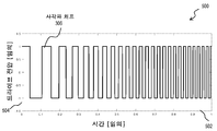
도 5a는, 일 실시예에 따른, 도 2a 및 도 2b의 LIDAR 시스템들에서 사용되는 사각파 디지털 처프 신호의 일 예를 예시하는 그래프이다.
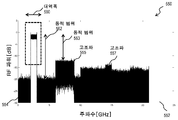
도 5b는, 일 실시예에 따른, 도 5a의 사각파 디지털 처프 신호의 주파수 스펙트럼의 일 예를 예시하는 그래프이다.
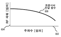
도 6a는, 일 실시예에 따른, 도 3a의 RF 파형 생성기의 사각파 디지털 처프 신호의 전달 함수의 일 예를 예시하는 그래프이다.
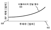
도 6b는, 일 실시예에 따른 도 3b의 RF 조절 컴포넌트들의 이퀄라이저(equalizer)의 전달 함수의 일 예를 예시하는 그래프이다.
도 6c는, 일 실시예에 따른, 도 3a의 RF 파형 생성기로부터 출력된 입력 디지털 처프 신호의 결과적인 함수의 일 예를 예시하는 그래프이다.
도 7은, 일 실시예에 따른, 도 4a의 입력 디지털 처프 신호를 사용하는 통상적인 LIDAR 시스템에서의 디-처핑으로부터 기인하는 비트 주파수의 예시적인 측정을 예시하는 그래프이다.
도 8은, 일 실시예에 따른, 도 5a의 사각파 디지털 처프 신호를 사용하는 LIDAR 시스템에서의 디-처핑으로부터 기인하는 비트 주파수의 예시적인 측정을 예시하는 그래프이다.
도 9는, 일 실시예에 따른, 광학적 처프형 거리 검출을 위해 사각파 디지털 처프 신호를 사용하기 위한 예시적인 방법을 예시하는 순서도이다.
도 10은 본 발명의 일 실시예가 구현될 수 있는 컴퓨터 시스템을 예시하는 블록도이다.
도 11은 본 발명의 일 실시예가 구현될 수 있는 칩 셋을 예시한다.Embodiments are illustrative and non-limitingly illustrated in the drawings of the accompanying drawings, in which like reference numbers refer to like elements.
1A is a set of graphs illustrating an example optical chirp measurement of a distance according to one embodiment.
1B is a graph illustrating example measurements of bit frequencies resulting from de-chirping, representing distance, according to one embodiment.
2A and 2B are block diagrams illustrating example components of a high resolution LIDAR system, according to various embodiments.
3A is a block diagram illustrating example components of an RF waveform generator of the LIDAR system of FIG. 2A, according to one embodiment.
3B is a block diagram illustrating exemplary components of RF conditioning of the RF waveform generator of FIG. 3A according to one embodiment.
3C is a block diagram illustrating example components of an RF waveform generator of the LIDAR system of FIG. 2B, according to one embodiment.
4A is a graph illustrating an example of an input digital chirp signal used in a typical LIDAR system, according to one embodiment.
4B is a graph illustrating an example of a frequency spectrum of the input digital chirp signal of FIG. 4A, according to one embodiment.
5A is a graph illustrating an example of a square wave digital chirp signal used in the LIDAR systems of FIGS. 2A and 2B, according to one embodiment.
5B is a graph illustrating an example of a frequency spectrum of the square wave digital chirp signal of FIG. 5A according to an embodiment.
6A is a graph illustrating an example of a transfer function of a square wave digital chirp signal of the RF waveform generator of FIG. 3A according to an embodiment.
FIG. 6B is a graph illustrating an example of a transfer function of an equalizer of the RF conditioning components of FIG. 3B according to one embodiment.
6C is a graph illustrating an example of the resulting function of the input digital chirp signal output from the RF waveform generator of FIG. 3A, according to one embodiment.
7 is a graph illustrating an example measurement of the bit frequency resulting from de-chipping in a conventional LIDAR system using the input digital chirp signal of FIG. 4A, according to one embodiment.
8 is a graph illustrating exemplary measurements of bit frequencies resulting from de-chipping in an LIDAR system using the square wave digital chirp signal of FIG. 5A, according to one embodiment.
9 is a flow diagram illustrating an example method for using a square wave digital chirp signal for optical chirped distance detection, according to one embodiment.
10 is a block diagram illustrating a computer system in which an embodiment of the present invention may be implemented.
11 illustrates a chip set in which an embodiment of the present invention can be implemented.
광학적 처프형 거리 검출을 위해 사각파 디지털 처프 신호를 사용하기 위한 방법 및 장치 및 시스템 및 컴퓨터-판독가능 매체가 설명된다. 다음의 설명에 있어서, 예시의 목적들을 위하여, 다수의 특정 세부사항들이 본 발명의 철저한 이해를 제공하기 위하여 기술된다. 그러나, 본 발명이 이러한 특정 상세내용들 없이 실시될 수 있다는 것이 당업자에게 자명할 것이다. 다른 사례들에 있어, 잘 알려진 구조들 및 디바이스들은, 본 발명의 모호하게 하는 것을 회피하기 위하여 블록도의 형태로 도시된다. Methods and apparatus and systems and computer-readable media for using square wave digital chirp signals for optical chirped distance detection are described. In the following description, for purposes of illustration, numerous specific details are set forth in order to provide a thorough understanding of the present invention. However, it will be apparent to those skilled in the art that the present invention may be practiced without these specific details. In other instances, well-known structures and devices are shown in block diagram form in order to avoid obscuring the present invention.
광범위한 범위를 기술하는 수치적 범위들 및 파라미터들이 근사들임에도 불구하고, 특정한 비-제한적 예들에서 기술되는 수치적 값들은 가능한 한 정밀하게 보고된다. 그러나, 임의의 수치적 값은 본질적으로, 이것의 작성 시점에서의 그들의 개별적인 테스트 측정들에서 발견되는 표준 편차로부터 필연적으로 기인하는 특정 오류들을 포함한다. 추가로, 문맥으로부터 달리 명백하지 않는 한, 본원에서 제공되는 수치적 값은 최소 유효 자릿수에 의해 주어지는 암시된 정밀도를 갖는다. 따라서, 값 1.1은 1.05 내지 1.15의 값을 암시한다. 용어 "약"은 주어진 값을 중심으로 하는 더 넓은 범위를 나타내기 위해 사용되며, 문맥으로부터 달리 명백하지 않은 한, 최소 유효 자릿수 근처의 더 광범위한 범위를 암시하며, 예컨대 "약 1.1"은 1.0 내지 1.2의 범위를 암시한다. 최소 유효 자릿수가 불명확한 경우, 용어 "약"은 2의 인자(factor)를 암시하며, 예를 들어, "약 X"는 0.5X 내지 2X의 범위 내의 값을 암시하고, 예를 들어, 약 100은 50 내지 200의 범위 내의 값을 암시한다. 또한, 본원에 개시된 모든 범위들은 그 안에 포함되는 임의의 그리고 모든 서브-범위들을 포괄하는 것으로서 이해되어야 한다. 예를 들어, "10보다 더 작은" 범위는 0의 최소 값과 10의 최대 값 사이의 (그리고 이를 포함하는) 임의의 그리고 모든 서브-범위들, 즉, 0과 동일하거나 또는 더 큰 최소 값과 10과 동일하거나 또는 더 작은 최대 값을 갖는 임의의 그리고 모든 서브-범위들, 예를 들어, 1 내지 4를 포함할 수 있다.Although the numerical ranges and parameters describing the broad range are approximations, the numerical values described in certain non-limiting examples are reported as precisely as possible. However, any numerical value essentially includes certain errors that inevitably result from the standard deviation found in their individual test measurements at the time of writing. Additionally, unless otherwise apparent from context, numerical values provided herein have an implied precision given by the least significant digit. Thus, the value 1.1 implies a value from 1.05 to 1.15. The term “about” is used to denote a wider range centered on a given value, and unless otherwise clear from the context, implies a wider range near the least significant digit, such as “about 1.1” from 1.0 to 1.2 Hints at the scope of If the least significant digit is unclear, the term "about" implies a factor of 2, for example, "about X" implies a value in the range of 0.5X to 2X, for example about 100 Indicates a value in the range of 50 to 200. Also, all ranges disclosed herein are to be understood as encompassing any and all sub-ranges subsumed therein. For example, a “less than 10” range is any and all sub-ranges between (and including) a minimum value of 0 and a maximum value of 10, that is, a minimum value equal to or greater than 0 Any and all sub-ranges having a maximum value equal to or less than 10, for example, 1 to 4.
이하에서 본 발명의 일부 실시예들은 처프형 LIDAR 시스템에서 하나 이상의 광학적 캐리어들을 변조하기 위해 광대역 RF 전기적 신호를 사용하는 것의 맥락에서 설명된다. 그러나, 본 발명이 이러한 맥락으로 한정되는 것은 아니다. 다른 실시예들에 있어서, 본 발명은: 위상 편이 키잉(keying), 온-오프 키잉, 주파수 편이 키잉 또는 광대역 잡음을 포함하는, 레인징에 대하여 유용한 파형들을 생성하기 위하여 광대역 파형 생성기를 사용하는 것의 맥락에서 사용될 수 있다. Some embodiments of the present invention are described below in the context of using a wideband RF electrical signal to modulate one or more optical carriers in a chirped LIDAR system. However, the present invention is not limited to this context. In other embodiments, the present invention is directed to using a wideband waveform generator to generate useful waveforms for ranging, including phase shift keying, on-off keying, frequency shift keying, or broadband noise. Can be used in context.
1. 처프형 검출 개괄 1. Overview of chirp type detection
도 1a는 일 실시예에 따른 거리의 예시적인 광학적 처프 측정을 예시하는 그래프들(110, 120, 130, 140)의 세트이다. 수평 축(112)은 4개의 그래프들 모두에 대하여 동일하며, 대략 밀리초(ms, 1 ms = 10-3 초)의 임의적인 단위의 시간을 나타낸다. 그래프(110)는 송신되는 광학적 신호로서 사용되는 광의 빔의 파워를 나타낸다. 그래프(110)에서 수직 축(114)은 임의적인 단위의 송신되는 신호의 파워를 나타낸다. 트레이스(trace)(116)는 시간 0에서 시작하는 제한된 펄스 지속기간 τ 동안 온이다. 그래프(120)는 송신되는 신호의 주파수를 나타낸다. 수직 축(124)은 임의의 단위의 송신되는 주파수를 나타낸다. 트레이스(126)는, 펄스의 주파수가 펄스의 지속기간 τ 동안 f1로부터 f2로 증가하며 그에 따라 대역폭 B = f2 - f1을 갖는다는 것을 나타낸다. 변화의 주파수 레이트(rate)는 (f2 - f1)/τ이다.1A is a set of
복귀 신호(returned signal)가 그래프(130)에 도시되며, 이는 시간을 나타내는 수평 축(112) 및 그래프(120)에서와 같이 주파수를 나타내는 수직 축(124)을 갖는다. 그래프(120)의 처프(126)가 또한 그래프(130) 상의 점선과 같이 플롯팅(plot)된다. 제 1 복귀 신호가 트레이스(136a)에 의해 주어지며, 이는 바로 강도가 감소되고 Δt만큼 지연된 송신된 기준 신호이다. 2R의 거리(distance)(여기에서 R은 목표까지의 거리임)를 커버한 이후에 외부 물체로부터 복귀 신호가 수신될 때, 지연된 시간 Δt에서 시작하는 복귀 신호는 2R/c에 의해 주어지며, 여기에서 c는 매체 내에서의 빛의 속도(대략 초당 3x10⁸ 미터, m/s)이다. 이러한 시간에 걸쳐, 주파수는, 지연 시간이 곱해진 변화의 주파수 레이트에 의해 주어지며 fR로 지칭되는 거리에 의존하는 양만큼 변화되었다. 이는 식 1a에 의해 주어진다. The returned signal is shown in
fR = (f2 - f1)/τ*2R/c = 2BR/cτ (1a)f R = (f 2 -f 1 ) / τ * 2R / c = 2BR / cτ (1a)
fR의 값은, 디-처핑(de-chirping)으로 지칭되는 시간 영역 믹싱 동작에서 송신된 신호(126)와 복귀 신호(136a) 사이의 주파수 차이에 의해 측정된다. 따라서 거리 R은 식 1b에 의해 주어진다.The value of f R is measured by the difference in frequency between the
R = fR c τ /2B (1b)R = f R c τ / 2B (1b)
물론, 복귀 신호가 펄스가 완전히 송신된 이후에 도착하는 경우, 즉, 2R/c가 τ보다 더 큰 경우, 식 1a 및 식 1b는 유효하지 않다. 이러한 경우에 있어서, 기준 신호는, 복귀 신호가 기준 신호와 중첩하는 것을 보장하기 위하여 알려진 또는 고정된 양만큼 지연된다. 기준 신호의 고정된 또는 알려진 지연 시간은 빛의 속도 c에 의해 곱해져서, 식 1b로부터 계산된 거리에 추가되는 추가적인 거리를 제공한다. 절대 거리가 매체 내에서의 빛의 속도의 불확실성에 기인하여 약화될 수 있지만, 이는 거의-일정한 오류이며 주파수 차이에 기초하는 상대적 거리들은 여전히 매우 정밀하다.Of course, if the return signal arrives after the pulse is completely transmitted, i.e., 2R / c is greater than τ, then equations 1a and 1b are invalid. In this case, the reference signal is delayed by a known or fixed amount to ensure that the return signal overlaps the reference signal. The fixed or known delay time of the reference signal is multiplied by the speed of light c, giving an additional distance in addition to the distance calculated from equation 1b. Although the absolute distance can be attenuated due to the uncertainty of the speed of light in the medium, this is an almost-constant error and relative distances based on frequency differences are still very precise.
일부 상황들에 있어서, 송신되는 광 빔에 의해 조명되는 스팟(spot)은, 반투명 물체의 전방 및 후방, 또는 LIDAR로부터 다양한 거리들에 있는 물체의 더 가까운 부분 및 더 먼 부분, 또는 조명되는 스팟 내의 2개의 별개의 물체들과 같은, 상이한 거리들에서 2개 이상의 상이한 산란체들과 마주친다. 이러한 상황들에 있어서, 제 2 감소된 강도 및 상이하게 지연된 신호가 또한 도달될 것이며, 이는 트레이스(136b)에 의해 그래프(130) 상에 표시된다. 이는, 식 1b를 사용하여 상이한 거리를 제공하는 fR의 상이한 측정된 값을 가질 것이다. 일부 상황들에 있어서, 다수의 복귀 신호들이 수신된다.In some situations, the spot illuminated by the transmitted light beam may be the front and rear of the translucent object, or the closer and farther parts of the object at various distances from the LIDAR, or within the illuminated spot. Two or more different scatterers are encountered at different distances, such as two separate objects. In these situations, a second reduced intensity and a differently delayed signal will also be reached, which is indicated on
그래프(140)는 제 1 복귀 신호(136a)와 기준 처프(126) 사이의 차이 주파수 fR을 도시한다. 수평 축(112)은 도 1a의 모든 다른 정렬된 그래프들에서와 같이 시간을 나타내며, 수직 축(134)은 훨씬 더 확장된 스케일로 주파수 차이를 나타낸다. 트레이스(146)는 송신되는 처프 동안 측정되는 일정한 주파수 fR을 도시하며, 이는 식 1b에 의해 주어지는 바와 같은 특정 거리를 나타낸다. 제 2 복귀 신호(136b)는, 존재하는 경우, 디-처핑 동안 상이하고 더 큰 값의 fR(미도시)을 야기할 것이며; 결과적으로, 식 1b를 사용하여 더 큰 거리를 산출할 것이다.The
디-처핑을 위한 일반적인 방법은 기준 광학적 신호 및 복귀 광학적 신호 둘 모두를 동일한 광학적 검출기로 보내는 것이다. 검출기의 전기적 출력 신호는, 검출기 상에서 수렴하는 2개의 신호들의 주파수의 차이와 동일하거나 또는 달리 이에 의존하는 비트 주파수에 의해 좌우된다. 이러한 전기적 출력 신호의 푸리에 변환은 비트 주파수에서 피크를 산출할 것이다. 이러한 비트 주파수는 테라헤르츠(THz, 1 THz = 1012 헤르츠)의 광학적 주파수 범위 내가 아니라 메가헤르츠(MHz, 1 MHz = 106 헤르츠 =106 초 당 사이클)의 라디오 주파수(RF) 범의 내이다. 이러한 신호들은, 마이크로프로세서 상에서 실행되는 고속 푸리에 변환(Fast Fourier Transform; FFT) 또는 특수하게 만들어진 FFT 또는 다른 디지털 신호 프로세싱(digital signal processing; DSP) 집적 회로와 같은 흔하고 값이 싼 RF 컴포넌트들에 의해 용이하게 프로세싱된다. 다른 실시예들에 있어서, 복귀 신호는 (로컬 오실레이터로서 처프와 대조적으로) 로컬 오실레이터(oscillator)로서 작용하는 연속파(continuous wave; CW) 톤(tone)과 혼합된다. 이는, 그 자체가 처프(또는 송신된 어떤 파형)인 검출된 신호를 야기한다. 이러한 경우에 있어서, 검출된 신호는, 본원에서 사용되는 것과의 용어 불일치를 제외하고는, Kachelmyer(1990년)에서 설명된 바와 같이 디지털 영역에서 매칭형 필터링(matched filtering)을 겪을 것이다. 단점은, 디지타이저(digitizer) 대역폭 요건이 일반적으로 더 높다는 것이다. 코히어런트(coherent) 검출의 긍정적인 측면들은 달리 유지된다. A common method for de-chipping is to send both the reference optical signal and the return optical signal to the same optical detector. The electrical output signal of the detector is dictated by the bit frequency which is equal to or otherwise dependent on the difference in frequency of the two signals converging on the detector. The Fourier transform of this electrical output signal will yield a peak at the bit frequency. This bit frequency is not within the optical frequency range of terahertz (THz, 1 THz = 10 12 hertz), but within the radio frequency (RF) range of megahertz (MHz, 1 MHz = 10 6 hertz = 10 6 cycles per second). These signals are facilitated by common and low-cost RF components, such as a Fast Fourier Transform (FFT) running on a microprocessor or a specially crafted FFT or other digital signal processing (DSP) integrated circuit. Processing. In other embodiments, the return signal is mixed with a continuous wave (CW) tone acting as a local oscillator (as opposed to chirp as a local oscillator). This results in a detected signal that is itself a chirp (or some waveform transmitted). In this case, the detected signal will undergo matched filtering in the digital domain, as described in Kachelmyer (1990), with the exception of the term mismatch with that used herein. The disadvantage is that the digitizer bandwidth requirements are generally higher. The positive aspects of coherent detection remain different.
도 1b는, 일 실시예에 따른, 거리를 나타내는, 디-처핑으로부터 기인하는 비트 주파수의 예시적인 측정을 예시하는 그래프이다. 수평 축(152)은 메가헤르츠로 주파수를 나타내며; 및 수직 축은 데시벨(dB, dB 단위의 파워 = 20 log(IR/ IT))로 송신되는 파워 밀도에 대한 복귀 신호 파워 밀도 IR을 나타낸다. 트레이스(156)는 FFT 회로에 의해 생성되는 바와 같은 광학적 검출기에 의한 전기적 출력 신호의 푸리에 변환이며, Adany 등(2009년)에 의해 공포된 데이터에 기초한다. 피크의 수평 위치는 fR을 제공하며, 이는 식 1b를 사용하여 거리를 추정하기 위해 사용된다. 이에 더하여, 피크의 다른 특성들이 복귀 신호를 설명하기 위해 사용될 수 있다. 예를 들어, 피크에서의 파워 값은 트레이스(156)의 최대 값에 의해 특징 지어지거나, 또는 더 일반적으로는, 피크의 숄더(shoulder)들에서의 잡음 플로어(noise floor)(도 1b에서 약 -50dB)와 피크 값(도 1b에서 약 -31 dB) 사이의 차이(157)(도 1b에서 약 19 dB)에 의해 특징 지어지며; 피크의 폭은 1/2 최대에서의 주파수 폭(158)(도 1b에서 약 0.08 MHz)(FWHM)에 의해 특징 지어진다. 다수의 식별할 수 있는 복귀들이 존재하는 경우, 아마도 다수의 상이한 파워 레벨들 및 폭들을 갖는, 광학적 검출기의 전기적 출력의 FFT 내에 다수의 피크들이 존재할 것이다. 자동으로 트레이스들에서 피크들을 식별하고, 위치, 높이 및 폭에 의해 이러한 피크들을 특징 짓기 위한 임의의 방법이 사용될 수 있다. 예를 들어, 일부 실시예들에 있어서, 메사추세츠 주, 나틱 소재의 MATHWORKSTM의 MATLABTM으로부터 입수할 수 있는 MATLAB - 신호 프로세싱 툴박스에 의한 FFTW 또는 피크 검출이 사용된다. 또한, 캘리포니아주, 산타 클라라 소재의 NVIDIATM로부터 입수할 수 있는 CUDATM에서 커스텀 피크 검출 및 CUDA에서 FFTW에 의존하는 커스텀 구현예들을 사용할 수 있다. 커스텀 구현예들은 필드 프로그램가능 게이트 어레이(FPGA)들 상에 프로그래밍되었다. 일반적으로 사용되는 알고리즘은, 피크의 위치를 더 정밀하게 결정하기 위하여 거리 프로파일을 임계화(threshold)하고, (가우시안과 같은) 어떤 함수의 피크의 비선형 피팅, 또는 피크 피팅 알고리즘(3-포인트 가우시안 피팅), 매스 알고리즘(mass algorithm)의 중심을 실행하는 것이다.1B is a graph illustrating an example measurement of the bit frequency resulting from de-chipping, representing a distance, according to one embodiment. Horizontal axis 152 represents the frequency in megahertz; And the vertical axis represents the return signal power density I R for the power density transmitted in decibels (power in dB, dB = 20 log (I R / I T )).
검출되는 목표(소스)가 속도 vs로 움직이고 있고 LIDAR 시스템(관찰자)이 2개를 연결하는 벡터 상에서 속도 vo로 움직이고 있는 경우, 복귀 신호는 도플러 편이될 수 있고 검출된 fR의 비트 주파수가 또한 편이되며, 이는 검출 거리에서의 오류들을 초래할 수 있다. 다수의 상황들에 있어서, 검출되는 물체의 형상은 다수의 복귀들의 상대적인 위치에 기초하여 식별된다. 따라서, 물체의 형상에 오류가 있을 수 있거나, 또는 물체를 식별하기 위한 능력이 훼손될 수 있다.If the target (source) to be detected is moving at velocity v s and the LIDAR system (observer) is moving at velocity v o on the vector connecting the two, the return signal can be Doppler shifted and the detected bit frequency of f R It is also biased, which can lead to errors in the detection distance. In many situations, the shape of the object to be detected is identified based on the relative location of the multiple returns. Thus, there may be an error in the shape of the object, or the ability to identify the object may be impaired.
복귀의 관찰되는 주파수 f'는 도플러 효과에 의해 복귀의 정확한 주파수 f와는 상이하며, 식 2a에 의해 근사화된다. The observed frequency f 'of the return is different from the exact frequency f of the return by the Doppler effect, and is approximated by equation 2a.
![]()
![]()
여기에서 c는 매체 내에서 빛의 속도이다. 관찰자 및 소스가 2개 사이의 벡터 상에서 동일한 방향으로 동일한 속도로 움직이고 있는 경우 2개의 주파수들이 동일하다는 것을 주목해야 한다. 2개의 주파수들 사이의 차이, Δf = f’-f는 도플러 편이 D이며, 이는, 정확하지 않은 경우, 거리 측정에서의 오류를 구성하고, 이는 식 2b에 의해 주어진다.Where c is the speed of light in the medium. It should be noted that the two frequencies are the same if the observer and source are moving at the same speed in the same direction on the vector between the two. The difference between the two frequencies, Δf = f'-f is the Doppler shift D, which, if not correct, constitutes an error in the distance measurement, given by Equation 2b.
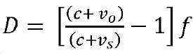
오류의 규모는 신호의 주파수 f에 따라 증가한다는 것을 주목해야 한다. 고정식 LIDAR 시스템(vo = 0)에 대하여, 초당 10 미터로 움직이는(vo = 10) 목표에 대하여, 그리고 약 500 THz의 주파수의 가시광에 대하여, 오류의 크기는 도 1b에서 약 22 MHz인 fR의 크기의 75%인 약 16 MHz이며 이는 fR에서의 75% 오류 및 그에 따라 거리에서의 75% 오류를 야기한다. 다양한 실시예들에 있어서, 도플러 편이 오류가 검출되며, 이는 거리를 교정하기 위해 사용된다.It should be noted that the magnitude of the error increases with the frequency f of the signal. For a fixed LIDAR system (v o = 0), for a target moving at 10 meters per second (v o = 10), and for visible light at a frequency of about 500 THz, the magnitude of the error is f of about 22 MHz in FIG. 75% of about 16 MHz the size of the R and which causes a 75% error, and 75% of the error in the distance accordingly in f R. In various embodiments, a Doppler shift error is detected, which is used to correct the distance.
2. 처프형 검출 하드웨어 개괄 2. Overview of chirp detection hardware
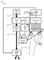
처프형 검출 접근 방식이 구현되는 방식을 도시하기 위하여, 어떤 포괄적이고 특정한 하드웨어 접근 방식들이 설명된다. 도 2a 및 도 2b는, 다양한 실시예들에 따른, 고 분해능 LIDAR 시스템의 예시적인 컴포넌트들을 예시하는 블록도들이다. 도 2a에서, 레이저 소스(212)는, 대역폭 B 및 지속기간 τ를 갖는 펄스를 생성하기 위하여 RF 파형 생성기(215)로부터의 입력에 기초하여 변조기(214) 내에서 주파수 변조되는 반송파(carrier wave)(201)를 방출한다. 이후의 섹션에서 더 상세하게 설명되는 다양한 실시예들에 있어서, RF 파형 생성기(215)로부터의 전기적 입력은 사각파 디지털 처프 신호에 기초하는 입력 디지털 처프 신호이다. 일 실시예에 있어서, 사각파 디지털 처프 신호는 RF 파형 생성기(215)에 의해 생성되고, RF 파형 생성기(215)에 의해 추가로 조절되며, 이는 입력 디지털 처프 신호를 야기한다. 이러한 실시예들 중 일부에 있어서, 입력 디지털 처프 신호는, 이러한 조절 없이, 사각파 디지털 처프 신호 자체이다. 일부 실시예들에 있어서, 사각파 디지털 처프 신호는, RF 파형 생성기(215)의 메모리 내로 업로딩된 사각파 명령어(217)에 기초하여 RF 파형 생성기(215)에 의해 생성된다. 다른 실시예들에 있어서, 프로세싱 시스템(250)의 거리 결정 모듈(270)은, 사각파 디지털 처프 신호의 생성을 포함하여 RF 파형 생성기(215)를 제어한다. 예시적인 실시예에 있어서, 사각파 명령어는 거리 결정 모듈(270) 내에 제공된다.To illustrate how the chirped detection approach is implemented, certain generic and specific hardware approaches are described. 2A and 2B are block diagrams illustrating example components of a high resolution LIDAR system, according to various embodiments. In FIG. 2A,
스플리터(216)는 변조된 광학적 파형을 빔(203)의 에너지의 대부분을 갖는 송신되는 신호(205)와, 훨씬 더 적지만 목표(미도시)로부터 산란된 복귀 광(291)과의 양호한 헤테로다인 또는 호모다인 간섭을 생성하기에는 충분한 양의 에너지를 갖는 기준 신호(207)로 분할한다. 일부 실시예들에 있어서, 송신되는 빔은 스캐닝 광학부(218)를 사용하여 그것의 경로 내의 임의의 물체를 프로파일링하기 위해 다수의 각도들에 걸쳐 스캐닝된다. The
기준 빔은 산란된 광과 함께 검출기 어레이(230)에 도착하기 위해 기준 경로(220) 내에서 충분히 지연된다. 일부 실시예들에 있어서, 스플리터(216)는 변조기(214)의 상류측에 존재하며, 기준 빔(207)은 변조되지 않는다. 일부 실시예들에 있어서, 기준 신호는 새로운 레이저(미도시)를 사용하여 독립적으로 생성되고, 생성기(215)로부터의 입력 디지털 처프 신호 및 기준 경로(220) 내의 별개의 변조기(미도시)를 사용하여 별도로 변조된다. 일부 실시예들에 있어서, 도 2b를 참조하여 이하에서 설명되는 바와 같이, 상이한 변조기가 사용되지만; 그러나, 단지 하나의 레이저 소스(212)가 코히어런스를 보장하기 위하여 송신되는 신호 및 기준 신호 둘 모두에 대해 사용된다. 다양한 실시예들에 있어서, 덜 유연한 접근 방식으로부터 더 유연한 접근 방식으로, 기준은: 1) 경로 길이가 잘 매칭되도록 검출기 어레이에서 송신 빔이 일 부분을 뒤로 반사시키기 위해 신(scene) 내에 거울을 배치함으로써; 2) 특정 거리에 대해 관찰되거나 또는 예상되는 위상 차이를 보상하기 위한 경로 길이 조정을 갖는 또는 갖지 않는, 도 2a에 제시된 바와 같은, 검출기 어레이 근처의 광학부를 가지고 기준 빔을 방송하고 경로 길이와 밀접하게 매칭하기 위해 섬유 지연을 사용함으로써; 또는 3) 경로 길이 미스매치를 보상하기 위한 별개의 변조를 생성하기 위해 로컬 오실레이터 파형 변조의 시간 지연 또는 주파수 편이 디바이스(음향-광학 변조기)를 사용함으로써; 또는 어떤 조합에 의해, 산란된 또는 반사된 필드를 가지고 도착하게끔 된다. 일부 실시예들에 있어서, 목표는, 지연 없이 복귀들이 기준 신호와 충분하게 중첩하도록 목표가 충분히 가깝고 펄스 지속기간이 충분히 길다. 일부 실시예들에 있어서, 기준 신호(207b)는 하나 이상의 광학적 믹서들(232)에서 복귀 신호(291)와 광학적으로 혼합된다. The reference beam is sufficiently delayed within the
일부 실시예들에 있어서, 기준 경로(220)는 RF 파형 생성기(215)로부터의 입력 디지털 처프 신호를 수신하는 위상 변조기를 포함하며, 여기에서 입력 디지털 처프 신호는 사각파 디지털 처프 신호에 기초한다. 이러한 실시예들에 있어서, 기준 경로(220)에서 수신되는 입력 디지털 처프 신호는 변조기(214)에서 수신된 입력 디지털 처프 신호와 독립적이다. 일 실시예에 있어서, 기준 신호(207)의 위상은, 유익하게는 광학적 믹서들(232)에서 기준 빔(207b)과 복귀 신호(291) 사이의 강도 잡음 편차들을 감소시키기 위하여 입력 디지털 처프 신호에 기초하여 위상 변조기에 의해 변조된다.In some embodiments, the
다양한 실시예들에 있어서, 목표의 다수의 부분들은, 각각의 스캐닝된 빔에 대하여 개별적인 복귀 광 빔(291)을 다시 검출기 어레이(230)로 산란시키며, 이는 다수의 빔들 및 다수의 복귀들에 의해 조명되는 목표의 개별적인 다수의 부분들의 다수의 거리들에 기초하는 포인트 클라우드(point cloud)를 야기한다. 검출기 어레이는 목표로부터의 복귀 빔(291)에 대해 대략적으로 수직인 평면에 배열되는 단일 또는 밸런스형(balanced) 쌍 광학적 검출기 또는 이러한 광학적 검출기들의 1D 또는 2D 어레이이다. 간섭 패턴의 위상 또는 진폭, 또는 어떤 조합은, 펄스 지속기간 τ 동안 각각의 검출기에 대한 획득 시스템(240)에 의해 여러 번 기록된다. 펄스 지속기간 당 시간적 샘플들의 수는 다운-레인지(down-range) 범위에 영향을 준다. 수는 보통 펄스 반복 레이트 및 이용가능 카메라 프레임 레이트에 기초하여 선택된 실제적인 고려사항이다. 프레임 레이트는 흔히 "디지타이저 주파수"로 지칭되는 샘플링 대역폭이다. 기본적으로, X개의 검출기 어레이 프레임들이 Y 거리 폭의 분해능 빈(bin)들을 가지고 펄스 동안 수집되는 경우, X*Y 거리 범위가 관찰될 수 있다. 획득된 데이터는 도 10을 참조하여 이하에서 설명되는 컴퓨터 시스템 또는 도 11을 참조하여 이하에서 설명되는 칩 셋과 같은 프로세싱 시스템(250)에 대하여 이용가능하게 만들어 진다. 일부 실시예들에 있어서, 획득된 데이터는 목표의 개별적인 다수의 부분들의 다수의 거리들에 기초하는 포인트 클라우드이다. In various embodiments, multiple portions of the target scatter a separate return
거리 결정 모듈(270)은 검출기 어레이(230)로부터의 전기적 출력 신호에 기초하여 목표까지의 거리를 계산한다. 일부 실시예들에 있어서, 거리 결정 모듈(270)은 출력 신호의 주파수 스펙트럼을 획득하기 위해 전기적 출력 신호의 푸리에 변환을 수행하고, 주파수 스펙트럼의 하나 이상의 특성들에 기초하여 목표까지의 거리를 계산한다. 일 실시예에 있어서, 거리 결정 모듈(270)은 도 1b에 도시된 전기적 출력 신호의 주파수 스펙트럼의 피크의 하나 이상의 특성들(예를 들어, fR의 주파수 값)에 기초하여 거리를 계산한다. 이러한 실시예에 있어서, 거리 결정 모듈(270)은 검출기 어레이(230)로부터의 출력 신호의 주파수 스펙트럼의 피크의 특성(예를 들어, fR) 및 식 (1b)를 사용하여 거리를 계산한다. 거리 결정 모듈(270)은 식 (1b)를 사용하여 다수의 거리들을 계산하며, 여기에서 다수의 피크들(예를 들어, fR의 다수의 값들)은 검출기 어레이(230)로부터의 출력 신호의 주파수 스펙트럼 내에 나타난다.The
다른 실시예들에 있어서, 모듈(270)은 도플러 편이의 크기 및 거기에 대한 교정된 거리를 결정하는 도플러 보상 모듈이다. 도플러 보상 모듈은 2016년 11월 30일자로 출원된 미국 가특허 출원 번호 제62/428,109호에서 논의된다. In other embodiments,
도 2b는, 사각파 디지털 처프 신호에 기초하는 입력 디지털 처프 신호가 RF 파형 생성기(215)로부터 LO 신호를 생성하는 기준 경로 내로 도입되는 것을 가능하게 하는 대안적인 하드웨어 배열을 도시한다. 일부 실시예들에 있어서, 기준 경로 내로 도입되는 입력 디지털 처프 신호는 송신 경로 내로 도입되는 입력 디지털 처프 신호와 독립적이다. 레이저 소스(212), 스플리터(216), 송신 신호(205), 스캐닝 광학부(218), 광학적 믹서들(232), 검출기 어레이(230), 획득 시스템(240) 및 프로세싱 시스템(250)은 도 2a를 참조하여 이상에서 설명된 바와 같다. 도 2b에서, 생성기(215)로부터의 입력 디지털 처프를 광학적 캐리어 상에 부과하기 위하여 송신 경로 내에 별개의 광학적 변조기(214a) 및 기준 경로(282) 내에 별개의 광학적 변조기들(214b), 즉, 2개의 별개의 광학적 변조기들이 존재한다. 2B shows an alternative hardware arrangement that enables an input digital chirp signal based on a square wave digital chirp signal to be introduced into the reference path for generating an LO signal from the
스플리터(216)는, 변조기(214a)에 영향을 주는 광학적 신호(283) 및 수정된 기준 경로(282) 내의 변조기(214b)에 영향을 주는 더 낮은 진폭 기준 신호 경로(287a)를 생성하기 위하여 변조기들(214a 및 214b)과 레이저 소스(212) 사이에서 이동된다. 이러한 실시예에 있어서, 변조가 발생하기 이전에 광(201)은 송신(TX) 경로 빔(283) 및 기준/로컬 오실레이터local oscillator; LO) 경로 빔(287a)으로 분할되며; 변개의 변조기들이 각각의 경로에서 사용된다. 듀얼 변조기 접근 방식을 이용하면, 각각의 경로는 오프셋 시작 주파수들 및/또는 오프셋 시작 시간들 및/또는 오프셋 시작 위상들에서 입력 디지털 처프 신호들을 가지고 프로그래밍될 수 있다. 각각의 거리 게이트에서 사용되는 지연을 시프팅함으로써, 시스템은, 다른 시스템 제한들(검출기 및 디지타이저 대역폭, 측정 시간 등)에도 불구하고 고 분해능을 가지고 명확하게 측정할 수 있다. 그러면, 소프트웨어 제어형 지연 기준 신호(287b)는 이상에서 설명된 바와 같이 복귀 신호들(291)과 혼합된다. 다른 실시예들에 있어서, LO 기준 경로(282)의 소프트웨어 제어형 지연은 적응적 스캐닝 접근 방식이 다운-레인지 차원에서도 마찬가지로 적응적이 되는 것을 가능하게 한다.The
일부 실시예들에 있어서, RF 파형 생성기(215)는 채널들의 쌍을 포함하며, 여기에서 제 1 채널은 변조기(214a)로 제 1 입력 디지털 처프 신호를 출력하고 제 2 채널은 변조기(214b)로 제 2 입력 디지털 처프 신호를 출력한다. 일부 실시예들에 있어서, 제 1 입력 디지털 처프 신호는 제 1 사각파 디지털 처프 신호에 기초하며, 제 2 입력 디지털 처프 신호는 제 2 사각파 디지털 처프 신호에 기초한다. In some embodiments,
일 실시예에 있어서, 변조기(214a)는, 송신 빔(283)의 주파수를 변조하기 위해 제 1 입력 디지털 처프 신호를 수신하고 대역폭 B 및 지속기간 τ를 갖는 송신되는 신호(205) 펄스를 생성하는 주파수 변조기이다. 다른 실시예에 있어서, 변조기(214b)는 RF 파형 생성기(215)로부터 제 2 입력 디지털 처프 신호를 수신하는 위상 변조기이다. 이러한 실시예들에 있어서, 변조기(214a)에서 수신되는 제 1 입력 디지털 처프 신호는 변조기(214b)에서 수신되는 제 2 입력 디지털 처프 신호와 독립적이다. 일 실시예에 있어서, 기준 신호(207)의 위상은, 유익하게는 광학적 믹서들(232)에서 기준 빔(207b)과 복귀 신호(291) 사이의 강도 잡음 편차들을 감소시키기 위하여 제 2 입력 디지털 처프 신호에 기초하여 위상 변조기에 의해 변조된다.In one embodiment,
일부 실시예들에 있어서, 사용되는 레이저는 전류 구동 레이저에 인가되는 변조를 가지고 능동적으로 선형화되었다. 실험들이 또한 변조를 제공하는 전기-광학적 변조기들을 가지고 수행되었다. 시스템은, 이하에서 다양한 실시예들에 대하여 더 상세하게 설명되는 바와 같이, 희망되는 다운-레인지 분해능에 대하여 적절한 대역폭 B 및 지속기간 τ의 처프를 생성하도록 구성된다. 예를 들어, 일부 예시된 실시예들에 있어서, 약 90 GHz의 B 및 약 200 밀리초(ms, 1 ms = 10-3 초)의 τ의 값이 수행된 실험들에서 상대적으로 낮은 검출기 어레이 프레임 레이트의 경계들 내에서 작동하도록 선택된다. 이러한 선택들은 약 30 cm의 합리적으로 큰 거리 윈도우를 관찰하기 위해 이루어졌으며, 이는 흔히 물체의 식별 및 물체의 형상을 결정하는데 중요하다. 이러한 기술은 10 MHz 내지 5 THz의 처프 대역폭에 대하여 작동할 것이다. 그러나, 3D 이미징 애플리케이션들에 대하여, 전형적인 거리들은 약 300 MHz 내지 약 20 GHz의 처프 대역폭들, 약 250 나노초(ns, ns = 10-9 초) 내지 약 1 밀리초(ms, 1 ms = 10-3 초)의 처프 지속기간들, 약 0 미터 내지 약 20 km의 목표들까지의 거리들, 약 3 밀리미터(mm, 1 mm = 10-3 미터) 내지 약 1 미터(m)의 목표에서의 스팟 크기들, 약 7.5 mm 내지 약 0.5 m의 목표에서의 깊이 분해능들이다. 거리 윈도우는 이러한 조건들 하에서 몇 킬로미터까지 확장되도록 만들어질 수 있으며, 도플러 분해능이 또한 (처프의 지속기간에 의존하여) 상당히 높을 수 있다는 것을 주목해야 한다. In some embodiments, the laser used is actively linearized with modulation applied to the current driven laser. Experiments were also performed with electro-optical modulators that provide modulation. The system is configured to generate a chirp of appropriate bandwidth B and duration τ for the desired down-range resolution, as described in more detail below for various embodiments. For example, in some illustrated embodiments, a B of about 90 GHz and a value of τ of about 200 milliseconds (ms, 1 ms = 10 -3 seconds) are relatively low detector array frames in experiments performed. It is chosen to operate within the boundaries of the rate. These choices were made to observe a reasonably large distance window of about 30 cm, which is often important for object identification and object shape determination. This technique will work for chirp bandwidths of 10 MHz to 5 THz. However, with respect to 3D imaging applications, typical distances of about 300 MHz to the chirp bandwidth of about 20 GHz, approximately 250 nanoseconds (ns, ns = 10 -9 seconds) to about 1 millisecond (ms, 1 ms = 10 - Chirp durations of 3 seconds, distances to targets of about 0 meters to about 20 km, spots at targets of about 3 millimeters (mm, 1 mm = 10 -3 meters) to about 1 meter (m) Sizes, depth resolution at a target of about 7.5 mm to about 0.5 m. It should be noted that the distance window can be made to extend to several kilometers under these conditions, and the Doppler resolution can also be quite high (depending on the duration of the chirp).
프로세스들, 장비, 및 데이터 구조들이 예시의 목적들을 위하여 특정한 배열의 일체적 블록들로서 도 2a 및 도 2b에 도시되지만, 다른 실시예들에 있어서, 하나 이상의 프로세스들 또는 데이터 구조들, 또는 이들의 부분들은, 하나 이상의 데이터베이스들 내에서, 동일하거나 또는 상이한 호스트들 상에 상이한 방식으로 배열되거나, 또는 생략되거나, 또는 하나 이상의 상이한 프로세스들 또는 데이터 구조들이 동일하거나 또는 상이한 호스트들 상에 포함된다. 예를 들어, 스플리터(216) 및 기준 경로(220)는 0개 또는 더 많은 광학적 커플러들을 포함한다. Although the processes, equipment, and data structures are shown in FIGS. 2A and 2B as integral blocks in a particular arrangement for purposes of illustration, in other embodiments, one or more processes or data structures, or portions thereof They are arranged in different ways on the same or different hosts, within one or more databases, or omitted, or one or more different processes or data structures are included on the same or different hosts. For example,
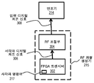
도 3a는, 일 실시예에 따른, 도 2a의 LIDAR 시스템(200)의 RF 파형 생성기(215)의 예시적인 컴포넌트들을 예시하는 블록도이다. 일 실시예에 있어서, RF 파형 생성기(215)는 사각파 디지털 처프 신호(306)를 생성하기 위한 트랜시버(302)를 포함한다. 일부 실시예들에 있어서, 트랜시버(302)는 필드 프로그램가능 게이트 어레이(FPGA)의 트랜시버이다. 일 실시예에 있어서, FPGA는 다른 기능들을 수행하기 위해 LIDAR 시스템(200)에 의해 사용되며, FPGA의 하나 이상의 달리 사용되지 않는 트랜시버(302)는 RF 파형 생성기(215)에 의해 액세스된다. 일 실시예에 있어서, FPGA의 트랜시버(302)는 약 32 GHz의 대역폭을 갖는다. 이러한 설명이 목적들을 위하여, 헤르츠(Hz)의 단위는 디지털 신호의 파라미터들을 논의할 때 초당 샘플들(Samples per second; SPS)의 단위와 상호교환적으로 사용된다. 이러한 실시예는 유익하게는 LIDAR 시스템(200)에서 광학적 캐리어를 변조하기 위한 광대역 디지털화된 처프 신호를 생성하기 위해 LIDAR 시스템(200)의 기존 컴포넌트를 이용한다. 예시적인 실시예에 있어서, FPGA는 또한 목표까지의 거리를 계산하기 위하여 및/또는 계산된 거리에 기초하여 이미지 데이터를 생성하기 위하여 프로세싱 시스템(250)에 의해 사용된다. 3A is a block diagram illustrating example components of the
일 실시예에 있어서, 디지털 처프 파형들은 FPGA 상의 프로세서 코어들 상에서 실행되는 소프트웨어에서 생성된다. 일부 실시예들에 있어서, 전통적인 FPGA들 상에서, 이러한 프로세서들은 FPGA 패브릭(fabric) 내에 구현된 소프트-코어 프로세서들이다. 다른 실시예들에 있어서, 시스템-온-칩(System-on-Chip; SoC) FPGA들 상에서, 프로그램가능 로직 패브릭과 함께 실리콘 내에 영구적으로 구현된 하드-코어 프로세서들이 존재한다.In one embodiment, digital chirp waveforms are generated in software running on processor cores on the FPGA. In some embodiments, on traditional FPGAs, these processors are soft-core processors implemented in an FPGA fabric. In other embodiments, on System-on-Chip (SoC) FPGAs, there are hard-core processors permanently implemented in silicon with a programmable logic fabric.
일 실시예에 있어서, 소프트웨어 알고리즘은, 처프 반복 레이트, 처프 시작 주파수, 처프 대역폭, 처프 방향, 및 출력 샘플 레이트와 같은 몇몇 파라미터들을 입력으로서 취하며, 출력으로서 처프 파형 데이터를 생성한다. 소프트웨어-생성형 파형들은, FPGA의 프로그램가능 로직 패브릭 내에 구현되는, 듀얼-포트 블록 랜덤-액세스 메모리(RAM) 엘리먼트들 내로 로딩된다. 이러한 RAM 블록들의 하나의 포트는 이러한 파형 로딩을 가능하게 하기 위해 프로세서 코어들에 연결되며; 다른 포트는 프로그램가능 로직 내의 유한 상태 머신(finite state machine; FSM)에 연결된다. 이러한 FSM은, 이음매가 없는(seamless) 반복 처프 생성을 위해 필요한 엄격한 타이밍 요건들 하에서 파형들을 판독하고 이들을 FPGA의 멀티-기기비트 트랜시버(multi-gigabit transceiver; MGT)들에 공급하도록 설계된다. FSM은 또한 프로세서 코어들 상에서 실행되는 소프트웨어에 의해 그 자체가 제어가능하며, 이는 완전한(full) 파형 생성 및 소프트웨어 환경으로부터의 제어를 가능하게 한다. In one embodiment, the software algorithm takes several parameters as input, such as chirp repetition rate, chirp start frequency, chirp bandwidth, chirp direction, and output sample rate, and generates chirp waveform data as output. Software-generated waveforms are loaded into dual-port block random-access memory (RAM) elements, implemented in the programmable logic fabric of the FPGA. One port of these RAM blocks is connected to the processor cores to enable this waveform loading; The other port is connected to a finite state machine (FSM) in programmable logic. This FSM is designed to read waveforms under the strict timing requirements required for seamless repeat chirp generation and feed them to the FPGA's multi-gigabit transceivers (MGTs). The FSM is also itself controllable by software running on processor cores, which enables full waveform generation and control from the software environment.
사각파 파형은, FPGA 트랜시버(302)로 업로딩되며 사각파 디지털 처프 신호(306)를 생성하기 위한 입력으로서 사용되는 명령어(217)의 적어도 일 부분으로 구성된다. 일부 실시예들에 있어서, 사각파 명령어(217)는 사각파 디지털 처프 신호(306)의 하나 이상의 파라미터들에 기초하여 파라미터화되는 비트스트림이다. 일 실시예에 있어서, 파라미터들은 시작 주파수, 정지 주파수, 펄스 지속기간 및 펄스 반복 주파수(pulse repetition frequency; PRF) 중 하나 이상을 포함한다. 예시적인 실시예에 있어서, 시작 주파수는 약 500 MHz이고, 정지 주파수는 약 14 GHz이며, 펄스 지속기간은 약 100 마이크로초(μsec)이고, PRF는 약 10 킬로헤르츠(kHz)이다. 일부 실시예들에 있어서, 사각파 명령어(217)는, 제 1 주파수보다 더 큰 제 2 주파수를 출력하기 위해 제 1 수의 클럭 사이클들보다 더 작은 제 2 수의 클럭 사이클들(예를 들어, 1100)에 걸쳐 고정된 진폭의 출력이 이어지는 제 1 주파수를 출력하기 위해 트랜시버(302)의 제 1 수의 클럭 사이클들(예를 들어, 111000)에 걸쳐 고정된 진폭의 출력을 나타내는 비트 스트림을 포함한다. 다른 실시예들에 있어서, 사각파 명령은 거리 결정 모듈(270) 내에 포함되며, FPGA 트랜시버(302) 내로 업로딩되는 것이 아니라 프로세싱 시스템(250)으로부터 FPGA 트랜시버(302)로 송신된다. The square wave waveform is composed of at least a portion of
일부 실시예들에 있어서, 사각파 명령(217)은 코사인 처프 파형(예를 들어, 도 4a의 코사인 처프(406) 신호)을 디지털화함으로써 결정된다. 일 실시예에 있어서, 각각의 클럭 사이클에서의 사각파 명령(217)의 비트스트림은 각각의 클럭 사이클에 대응하는 시간 증분(increment)에서 코사인 처프 파형의 인수(argument)에 기초하여 결정된다. 일 실시예에 있어서, 비트스트림은 이러한 시간 증분들에 대하여 1로 설정되며, 여기에서 코사인 처프 파형의 인수는 단위 원의 우측 절반 상에 있다. 이러한 실시예에 있어서, 비트스트림은 그들의 시간 증분들에 대해 0으로 설정되며, 여기에서 코사인 처프 파형의 인수는 단위 원의 좌측 절반 상에 있다. 이는 유익하게는, 예를 들어, 코사인 함수를 계산하기 위한 다른 방법 또는 룩-업(look-up) 테이블을 가지고 작동하는 자원 집중 단계들을 회피하며, 그에 따라 사각파 명령어(217)를 계산하기 위해 효율적인 방법을 제공한다. In some embodiments, the
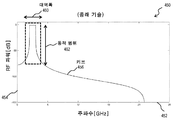
도 4a는, 일 실시예에 따른, 통상적인 LIDAR 시스템에서 사용되는 입력 디지털 처프 신호의 일 예를 예시하는 그래프(400)이다. 수평 축(402)은 임의적인 단위로 측정되는 시간이다. 수직 축(404)은 임의적인 단위로 측정되는 전압이다. 일 실시예에 있어서, 입력 디지털 처프 신호는, 시간의 경과에 따라 제 1 주파수로부터 제 1 주파수보다 더 큰 제 2 주파수로 선형적으로 증가하는 코사인 처프(406)이다. 도 4b는, 일 실시예에 따른, 도 4a의 입력 디지털 처프 신호의 주파수 스펙트럼의 일 예를 예시하는 그래프(450)이다. 수평 축(452)은 기가헤르츠(GHz)의 단위의 주파수이며, 수직 축(454)은 데시벨(dB)의 단위의 파워이다. 일 실시예에 있어서, 커브(456)는 코사인 처프(406) 신호의 주파수 스펙트럼을 나타낸다. 주파수 스펙트럼의 대역폭(460)은 제 1 주파수로부터 제 2 주파수까지 연장한다. 일 실시예에 있어서, 대역폭(460)은 약 500 MHz 내지 약 10 GHz의 범위 내이다. 추가적으로, 동적 범위(dynamic range)(462)는 대역폭(460) 내의 커브(456)의 진폭과 대역폭(460) 외부의 커브(456)의 진폭 사이의 차이로서 정의된다. 동적 범위(462)는 적어도 50 dB이다.4A is a
도 5a는, 일 실시예에 따른, 도 2a 및 도 2b의 LIDAR 시스템들(200, 280)에서 사용되는 사각파 디지털 처프 신호(306)의 일 예를 예시하는 그래프(500)이다. 수평 축(502)은 임의적인 단위로 측정되는 시간이다. 수직 축(504)은 임의적인 단위로 측정되는 전압이다. 일 실시예에 있어서, 사각파 디지털 처프 신호(306)는 시간의 경과에 따라 제 1 주파수로부터 제 1 주파수보다 더 큰 제 2 주파수까지 선형적으로 증가한다. 도 5b는, 일 실시예에 따른, 도 5a의 사각파 디지털 처프 신호(306)의 주파수 스펙트럼의 일 예를 예시하는 그래프(550)이다. 수평 축(552)은 기가헤르츠(GHz)의 단위의 주파수이며, 수직 축(554)은 데시벨(dB)의 단위의 파워이다. 5A is a
일부 실시예들에 있어서, 도 3a의 RF 파형 생성기(215)는 사각파 디지털 처프 신호(306)를 변조기(214)로 입력되는 도 3a의 입력 디지털 처프 신호(308)로 변환하기 위하여 하나 이상의 조절 단계들을 수행하는 RF 조절부(304) 컴포넌트들을 포함한다. 일부 실시예들에 있어서, 조절 단계들은 도 5b의 사각파 디지털 처프 신호(306)의 주파수 스펙트럼을 수정하며, 그 결과 입력 디지털 처프 신호(308)의 결과적인 주파수 스펙트럼은 도 4b에서 입력 디지털 처프 신호의 주파수 스펙트럼과 하나 이상의 특성들을 공유한다. 일 실시예에 있어서, 도 4b의 입력 디지털 처프 신호의 주파수 스펙트럼의 특성들은 대역폭(460) 및/또는 동적 범위(462)를 포함한다. In some embodiments, the
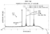
도 3b는, 일 실시예에 따른 도 3a의 RF 파형 생성기(215)의 RF 조절부(304)의 예시적인 컴포넌트들을 예시하는 블록도이다. 일부 실시예들에 있어서, RF 조절부(304) 컴포넌트들은, 도 5b의 사각파 디지털 처프 신호(306)의 주파수 스펙트럼으로부터 주파수들의 범위를 제거하기 위해 사용되는 필터(310)를 포함한다. 일 실시예에 있어서, 필터(310)는, 도 4b에서 대역폭(460)과 중첩하는 주파수들의 범위를 통과시키고 코사인 처프(406) 신호들의 대역폭(460) 외부에 속하는 주파수들의 범위를 제거하는 대역-통과 필터이다. 일부 실시예들에 있어서, 사각파 디지털 처프 신호(306)의 주파수 스펙트럼 내의 더 높은 차수의 고조파(harmonic)들(555, 557)이 필터(310)에 의해 제거된다. 이러한 실시예에 있어서, 필터(310)는 도 5b의 사각파 디지털 처프 신호(306)의 주파수 스펙트럼으로부터 (예를 들어, 5 GHz 이상의) 주파수들의 범위를 제거한다. 예시적인 실시예에 있어서, 고차 저역-통과 필터들은 3차 및 더 높은 고조파들을 상당히 감쇠시키기 위해 사용된다. 일부 실시예들에 있어서, 필터링은 유익하게는 디지털 파형을 RF 회로부에서 사용하기 위한 사인 파형으로 변환한다. 예시적인 실시예에 있어서, 주파수들의 범위는, 주파수들의 배제된 범위가 더 높은 차수의 고조파들(555, 557)을 포함하도록 제거된다. 당업자에 의해 이해되는 바와 같이, 더 높은 차수의 고조파들(555, 557)은 도 5a의 사각파 처프(306)의 결과적인 주파수 성분들이다. 3B is a block diagram illustrating exemplary components of the
주파수 스펙트럼으로부터 주파수들의 범위를 제거하기 위해 필터(310)를 사용한 이후에, 결과적인 대역폭(560)은 입력 디지털 처프 신호(308)의 주파수 스펙트럼이다. 일부 실시예들에 있어서, 대역폭(560)은 도 4b에서 입력 디지털 처프 신호의 대역폭(460)과 중첩한다. 일부 실시예들에 있어서, 입력 디지털 처프 신호(308)의 대역폭(560)은 입력 디지털 처프 신호의 대역폭(460)을 초과한다. 다양한 실시예들에 있어서, 대역폭(560)은 약 2 GHz 내지 약 30 GHz의 범위이다. 바람직하게는, 대역폭(560)은 약 10 GHz 내지 약 30 GHz의 범위이다. 예시적인 일 실시예에 있어서, 대역폭(560)은 약 2 GHz 내지 약 3 GHz의 범위이다. 일반적으로, 입력 디지털 처프 신호(308)의 대역폭은 제 1 주파수로부터 제 2 주파수까지 연장한다. 예시적인 실시예에 있어서, 제 1 주파수는 약 500 MHz 내지 약 2 GHz의 범위 내이며, 제 2 주파수는 약 3 GHz 내지 약 32 GHz의 범위 내이다. 도 5b가 2-3 GHz의 범위 내의 대역폭(560)을 도시하지만, 이는 단지 하나의 예시적인 실시예이다. After using filter 310 to remove a range of frequencies from the frequency spectrum, the resulting
다른 실시예들에 있어서, 필터(310)는, 입력 디지털 처프 신호(308)에 대한 최소 동적 범위를 수립하기 위하여, 도 5b에서 사각파 디지털 처프 신호(306)의 주파수 파워 스펙트럼으로부터 주파수들의 범위를 제거한다. 동적 범위는 대역폭(560) 내의 주파수 파워 스펙트럼의 진폭과 대역폭(560) 외부의 주파수 파워 스펙트럼의 진폭 사이의 차이로서 정의된다. 도 5b에 도시된 바와 같이, 필터(310)를 가지고 주파수들의 범위(예를 들어, 고조파들(555, 557))를 제거하기 이전에, 동적 범위(563)는 약 10 dB, 예를 들어, 대역폭(560) 내의 약 0 dB와 더 높은 차수의 고조파(555)에서의 약 - 10 dB 사이의 차이이다. 주파수들의 범위(예를 들어, 고조파들(555, 557))를 제거한 이후에, 동적 범위(562)는 약 20 dB까지, 예를 들어, 대역폭(560) 내에서의 약 0 dB와 잡음 플로어에서의 약 -20 dB 사이의 차이까지 증가된다. 일 실시예에 있어서, 입력 디지털 처프 신호(308)의 최소 동적 범위는 약 20 dB 내지 약 50 dB의 범위 내이다. In other embodiments, the filter 310 ranges frequencies from the frequency power spectrum of the square wave
도 5b에 도시된 주파수 스펙트럼의 진폭이 대역폭(560)에 걸쳐 상대적으로 평평하지만, 일부 실시예들에 있어서, 진폭은 대역폭(560)에 걸쳐 불균등하다. 일 실시예에 있어서, 진폭이 대역폭(560) 내에서 더 낮은 주파수들에서 더 크고 더 높은 주파수들에서 더 작아지도록 진폭이 더 높은 주파수들에서 점점 줄어든다. 이는, 입력 디지털 처프 신호(308)의 주파수 스펙트럼이 대역폭(560)에 걸쳐 동일한 진폭을 갖는 경우에 믹싱을 위해 유익하다. Although the amplitude of the frequency spectrum shown in FIG. 5B is relatively flat across the
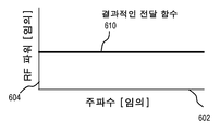
일부 실시예들에 있어서, 도 3b의 RF 조절부(304) 컴포넌트들은 대역폭(560)에 걸쳐 입력 디지털 처프 신호(308)의 주파수 스펙트럼의 진폭을 평탄화하기 위해 사용되는 이퀄라이저(312)를 포함한다. 도 6a는, 대역폭(560)에 걸쳐 주파수 스펙트럼의 진폭을 도시하는 전달 함수(606)의 일 예를 예시하는 그래프이다. 수평 축(602)은 임의적인 단위의 주파수이며, 수직 축(604)은 임의적인 단위의 파워이다. 필터(310)가 사각파 디지털 처프 신호(306)로부터 주파수들의 범위를 제거한 이후에, 필터링된 신호(311)는, 그것의 진폭이 대역폭(560)에 걸쳐 전달 함수(606)를 닮은 주파수 스펙트럼을 가지고 이퀄라이저(312)에서 수신된다. 일부 실시예들에 있어서, 전달 함수(606)는 트랜시버(302)의 특성이며, 이는 대역폭(560)에 걸쳐 사각파 디지털 처프 신호의 주파수 스펙트럼의 진폭을 도시한다. 도 6b는, 다른 실시예에 따른, 필터링된 전달 함수(606) 및/또는 트랜시버의 임의의 불리한 형상을 보상하기 위해 삽입된 도 3b의 RF 조절부 컴포넌트들의 이퀄라이저(312)에 대한 전달 함수(608)의 일 예를 예시하는 그래프이다. 수평 축(602)은 임의적인 단위의 주파수이며, 수직 축(604)은 임의적인 단위의 파워이다. 일부 실시예들에 있어서, 이퀄라이저(312)는 필터(310)로부터 필터링된 신호(311)를 수신하며, 전달 함수(608)에 따라 대역폭(560)에 걸쳐 필터링된 신호의 주파수 스펙트럼의 진폭을 확대한다. 도 6c는, 일 실시예에 따른, 도 3a의 RF 파형 생성기(215)로부터 출력된 입력 디지털 처프 신호(308)의 결과적인 함수(610)의 일 예를 예시하는 그래프이다. 이퀄라이저(312)가 전달 함수(608)를 사용하여 대역폭(560)에 걸쳐 필터링된 신호(311)의 주파수 스펙트럼을 확대한 이후에, 결과적인 함수(610)는 대역폭(560)에 걸쳐 입력 디지털 처프 신호(308)의 주파수 스펙트럼의 진폭을 도시한다. 일부 실시예들에 있어서, 주파수 스펙트럼의 진폭은 대역폭(560)에 걸쳐 대략 동일하다. 예시적인 일 실시예에 있어서, 주파수 스펙트럼의 진폭은 대역폭(560)에 걸쳐 약 10% 평탄도 내이다. 다른 예시적인 실시예에 있어서, 주파수 스펙트럼의 진폭은 대역폭(560)에 걸쳐 3-6 dB 편차를 특징으로 한다. 일부 실시예들에 있어서, 이것이 변조기(214)에 입력되기 이전에 입력 디지털 처프 신호(308)를 증폭하기 위해 RF 증폭기(314)가 제공된다. In some embodiments, the
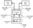
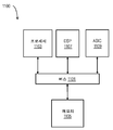
도 3c는, 일 실시예에 따른, 도 2b의 LIDAR 시스템(280)의 RF 파형 생성기(215)의 예시적인 컴포넌트들을 예시하는 블록도이다. 도 3c의 RF 파형 생성기(215)는, FPGA 트랜시버(302)가 복수의 사각파 디지털 처프 신호들(306a, 306b)을 생성하기 위한 복수의 채널들(예를 들어, 2개의 채널들)을 포함한다는 점을 제외하면, 도 3a의 파형 생성기(215)와 유사하다. 추가적으로, 도 3c의 RF 파형 생성기(215)는 입력 디지털 처프 신호들(308a, 308b)을 생성하기 위해 사각파 디지털 처프 신호들(306a, 306b)의 각각에 대하여 하나 이상의 조절 단계들을 수행하는 RF 조절부(304) 컴포넌트들을 포함한다. 일 실시예에 있어서, 제 1 입력 디지털 처프 신호(308a)는 송신 경로 빔(283)의 주파수를 변조하기 위해 변조기(214a)에 입력되며, 제 2 입력 디지털 처프 신호(308b)는 기준 경로 빔(287a)의 위상을 변조하기 위해 변조기(214b)에 입력된다. 기준 경로 신호(287a)의 위상의 변조는 유익하게는, 기준 경로 신호(287b)와 복귀 신호(291) 사이의 강도 편차들로부터 기인하는 검출기 어레이(230)에서의 잡음을 감소시킨다. 일부 실시예들에 있어서, 사각파 디지털 처프 신호(306a, 306b)는, 이들이 하나 이상의 구별되는 파라미터들(예를 들어, 시작 주파수, 정지 주파수, 펄스 지속기간, 펄스 반복 주파수)을 특징으로 하도록 독립적이다. 일 실시예에 있어서, 도 3c의 FPGA 트랜시버(302) 내로 업로딩된 사각파 명령어(207)는 각각의 사각파 디지털 처프 신호(306a, 306b)에 대한 별개의 명령어들을 포함한다. 3C is a block diagram illustrating example components of the
도 7은, 일 실시예에 따른, 도 4a의 입력 디지털 처프 신호(406)를 사용하는 통상적인 LIDAR 시스템에서의 디-처핑으로부터 기인하는 비트 주파수의 예시적인 측정을 예시하는 그래프이다. 수평 축(702)은 MHz의 단위로 측정되는 주파수이다. 수직 축(704)은 데시벨(dB, dB 단위의 파워 = 20 log(IR/ IT))로 송신되는 파워 밀도 IT에 대한 복귀 신호 파워 밀도 IR을 나타낸다. 커브(706)는 비트 주파수에 걸친 파워 스펙트럼의 진폭을 도시한다. 복수의 거리 복귀 피크들(708a, 708b, 708c)이 도시되며, 여기에서 거리 복귀 피크는, 예를 들어, 상이한 물체들 또는 물체의 상이한 부분들까지의 개별적인 거리 측정을 나타낸다. 일 실시예에 있어서, 각각의 피크(708a, 708b, 708c)의 수평 위치는 개별적인 거리를 계산하기 위하여 식 (1b)와 함께 사용되는 fR의 개별적인 값을 제공한다. 동적 범위(712)는 복귀 피크(708)에서의 커브(706)의 진폭(예를 들어, -40 dB)과 잡음 플로어에서의 커브(706)의 진폭(예를 들어, -80 dB) 사이에 측정된다. 일 실시예에 있어서, 동적 범위(712)는 약 40 dB이다. 일부 실시예들에 있어서, 약 20 dB 내지 약 40 dB 사이의 최소 동적 범위는 정확한 거리 검출을 보장한다.FIG. 7 is a graph illustrating exemplary measurements of bit frequencies resulting from de-chipping in a typical LIDAR system using the input digital chirp signal 406 of FIG. 4A, according to one embodiment. The
도 8은, 일 실시예에 따른, 도 5a의 사각파 디지털 처프 신호(306)를 사용하는 LIDAR 시스템(200)에서의 디-처핑으로부터 기인하는 비트 주파수의 예시적인 측정을 예시하는 그래프이다. 수평 축(802)은 MHz의 단위의 주파수이다. 수직 축(804)은 데시벨(dB, dB 단위의 파워 = 20 log(IR/ IT))로 송신되는 파워 밀도 IT에 대한 복귀 신호 파워 밀도 IR을 나타낸다. 커브(806)는 비트 주파수에 걸친 파워 주파수 스펙트럼의 진폭을 도시한다. 복수의 거리 복귀 피크들(808a, 808b, 808c)이 도시되며, 여기에서 거리 복귀 피크는, 예를 들어, 상이한 물체들 또는 물체의 상이한 부분들까지의 개별적인 거리 측정을 나타낸다. 각각의 피크(808a, 808b, 808c)의 수평 위치는 개별적인 거리를 계산하기 위하여 식 (1b)와 함께 거리 결정 모듈(270)에 의해 사용되는 fR의 개별적인 값을 제공한다. 추가적으로, 복수의 스퓨리어스(spurious) 피크들(810a, 810b)이 도시되며, 이들은, 사각파 디지털 처프 신호(306)가, 예를 들어, RF 조절부(304)의 부재 시에, 변조기(214)로 입력되는 경우에 획득된다. 스퓨리어스 피크들(810a, 810b)은 도 7에서 대응하는 피크들을 갖지 않으며, 따라서, RF 조절(304)이 사각파 디지털 처프 신호(306)에 대하여 수행되지 않는 한 잘못된 거리 계산들을 야기할 것이다. RF 조절부(304)는 유익하게는 비트 주파수 커브(806)로부터 스퓨리어스 피크들(810a, 810b)을 제거하며, 그럼으로써 잘못된 거리 계산들을 회피한다. 8 is a graph illustrating example measurements of bit frequencies resulting from de-chipping in
동적 범위(812)는 복귀 피크(808)에서의 커브(806)의 진폭(예를 들어, -35 dB)과 잡음 플로어에서의 커브(806)의 진폭(예를 들어, -80 dB) 사이에 측정된다. 일 실시예들에 있어서, 동적 범위(812)는 정확한 거리 검출을 위해 최소 동적 범위(예를 들어, 20 dB)보다 더 큰 약 35 dB이다. 스퓨리어스 피크들(810a, 810b)을 제거함으로써, RF 조절부는 또한 유익하게는 동적 범위(812)를 정확한 거리 검출을 위한 최소 동적 범위 이상으로 증가시켰다. 일부 실시예들에 있어서, RF 조절부(304)가, 예를 들어, 복귀 피크들(708)의 진폭에 비하여 복귀 피크들(808)의 진폭을 감소시키더라도, 동적 범위(812)는 정확한 거리 검출을 위한 최소 동적 범위를 초과한다. The
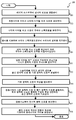
도 9는, 일 실시예에 따른, 광학적 처프형 거리 검출을 위해 사각파 디지털 처프 신호(306)를 사용하기 위한 예시적인 방법(900)을 예시하는 순서도이다. 도 9의 순서도가 예시의 목적들을 위하여 특정한 순서로 일체적 단계들로서 도시되지만, 다른 실시예들에 있어서, 하나 이상의 단계들, 또는 이들의 부분들은, 상이한 순서로, 또는 시간적으로 중첩하여, 직렬로 또는 병렬로 수행되거나, 또는 생략되거나, 또는 하나 이상의 추가적인 단계들이 추가되거나, 또는 방법이 방식들의 어떤 조합으로 변화된다. 9 is a flow diagram illustrating an
단계(901)에서, 광학적 신호가 레이저 소스로부터 방출된다. 일 실시예에 있어서, 단계(901)에서, 반송파(201)가 도 2a의 시스템(200) 내의 레이저 소스(212)로부터 방출된다. 다른 실시예들에 있어서, 단계(901)에서, 반송파(201)가 레이저 소스(212)로부터 방출되고, 그 후에 스플리터(216)가 도 2b의 시스템(280) 내에서 반송파(201)를 송신 경로 빔(283) 및 기준 경로 신호(287a)로 분할한다.In step 901, an optical signal is emitted from the laser source. In one embodiment, at step 901,
단계(903)에서, 사각파 디지털 처프 신호가 트랜시버를 가지고 생성된다. 일 실시예에 있어서, 단계(903)에서, 사각파 디지털 처프 신호(306)는 FPGA로부터 트랜시버(302) 내에서 생성된다. 다른 실시예에 있어서, 사각파 디지털 처프 신호(306)는 칩 상의 임의의 고속 직렬 트랜시버에 의해 생성된다. 예시적인 실시예에 있어서, 사각파 디지털 처프 신호(306)는 디지털 신호 프로세서(digital signal processor; DSP)에 의해 생성된다. 예시적인 일 실시예에 있어서, DSP는 애플리케이션 특정 집적 회로(Application-specific integrated circuit; ASIC) 상에 구현된다. 일부 실시예들에 있어서, 단계(903)에서, FPGA 트랜시버(302) 내의 업로딩된 사각파 명령어(207)가 실행되어 사각파 디지털 처프 신호(306)를 생성한다. 다른 실시예들에 있어서, 단계(903)에서, 사각파 명령은 거리 결정 모듈(270) 내에 포함되며, 사각파 디지털 처프 신호(306)를 생성하기 위하여 프로세싱 시스템(250)으로부터 FPGA 트랜시버(302)로 통신된다. 다른 실시예들에 있어서, 디지털 신호들의 다른 소스들이 사용된다. In
일 실시예에 있어서, 단계(903)에서, 단일 사각파 디지털 처프 신호(306)가 트랜시버(302) 내에서 생성되며, 트랜시버(302)의 단일 채널로부터 출력된다. 다른 실시예들에 있어서, 단계(903)에서, 복수의 사각파 디지털 처프 신호들(306a, 306b)이 트랜시버 내에서 생성되며, 트랜시버(302)의 복수의 채널들로부터 출력된다. In one embodiment, at
단계(905)에서, 단계(903)에서 생성된 사각파 디지털 처프 신호(306)의 주파수 스펙트럼이 결정된다. 일 실시예에 있어서, 사각파 디지털 처프 신호(306)의 주파수 스펙트럼은 도 5B에 도시되며, 고차 고조파들(555, 557)을 포함한다. 사각파 디지털 처프 신호(306)의 주파수 스펙트럼이 미리 결정된 일부 실시예들에 있어서, 단계(905)가 생략된다. In
단계(907)에서, 주파수들의 범위는 단계(905)에서 결정된 사각파 디지털 처프 신호(306)의 주파수 스펙트럼으로부터 제거된다. 일부 실시예들에 있어서, 단계(907)에서, 주파수들의 범위는 필터(310)를 가지고 제거된다. 일부 실시예들에 있어서, 단계(907)에서, 필터(310)는, 대역폭(560) 내의 주파수들의 범위를 송신하고 주파수 스펙트럼의 대역폭(560) 외부의 주파수들의 하나 이상의 범위들을 제거하는 대역-통과 필터이다. 일 실시예에 있어서, 대역폭(560)은 코사인 처프 신호(406)에 대한 주파수 스펙트럼의 대역폭(460)에 기초한다. 일부 실시예들에 있어서, 단계(907)에서, 대역폭(560)이 대역폭(460)과 중첩하고 대역폭(560)이 약 10 GHz 내지 약 30 GHz의 범위 내에 있도록, 주파수들의 범위가 필터(310)를 가지고 제거된다. 다른 실시예들에 있어서, 단계(907)에서, 주파수들의 범위는, 동적 범위(563)(예를 들어, 10 dB)가 동적 범위(562)(예를 들어, 20 dB)까지 증가되도록 필터(310)를 가지고 제거된다. 일부 실시예들에 있어서, 증가된 동적 범위(562)는 정확한 거리 검출을 위해 최소 동적 범위(예를 들어, 20 dB)를 초과한다. 일부 실시예들에 있어서, 단계(907)에서, 필터(310)는 더 높은 차수의 고조파들(555, 557)을 포함하는 주파수들의 범위를 제거한다. 예시적인 실시예에 있어서, 필터(310)는 더 높은 차수의 고조파들(555, 557)을 제거하기 위해 임계 주파수(예를 들어, 5 GHz) 이상의 주파수들의 범위를 제거한다. 사각파 디지털 처프 신호(306)의 주파수 스펙트럼이 미리 결정되는 일부 실시예들에 있어서, 단계(905)가 생략되며, 단계(907)는 미리 결정된 주파수 스펙트럼에 기초하여 주파수들의 범위를 제거한다. 일부 실시예들에 있어서, 단계(907)에서, 필터(310)는 사각파 디지털 처프 신호(306)를 이퀄라이저(312) 상에 입사하는 필터링된 신호(311)로 변환한다. In
단계(909)에서, 단계(907)로부터의 주파수 스펙트럼의 진폭은 입력 디지털 처프 신호(308)를 생성하도록 이퀄라이징된다. 일 실시예에 있어서, 대역폭(560)에 걸친 필터링된 신호(311)의 주파수 스펙트럼의 진폭은 전달 함수(606)를 닮으며, 예를 들어, 대역폭(560) 내의 더 높은 주파수들에서 줄어든다. 일 실시예에 있어서, 단계(909)에서, 이퀄라이저(612)는 전달 함수(608)에 따라 대역폭(560)에 걸쳐 필터링된 신호(311)의 주파수 스펙트럼의 진폭을 확대한다. 대역폭(560)에 걸친 입력 디지털 처프 신호(308)의 주파수 스펙트럼의 결과적인 진폭은 결과적인 전달 함수(610)를 닮으며, 예를 들어, 대역폭(560)에 걸쳐 대략적으로 동일하다. 일부 실시예들에 있어서, 입력 디지털 처프 신호(308)는 RF 증폭기(314)에 의해 증폭되며, 그런 다음 변조기(214)로 입력된다. In
다른 실시예들에 있어서, 임의의 디지털 대 아날로그 컨버터가 업로딩된 사각파 명령어(207)에 기초하여 입력 디지털 처프 신호(308)를 생성하기 위해 단계들(903, 905, 907, 909)에서 또는 그 대신에 사용될 수 있다. 당업자에 의해 이해될 바와 같이, 디지털 대 아날로그 컨버터의 선택은 비트-깊이와 대역폭 사이의 트레이드오프(tradeoff)를 수반한다. In other embodiments, in
단계(911)에서, 단계(901)에서의 광학적 신호의 주파수가 단계(909)로부터의 입력 디지털 처프 신호(308)에 기초하여 변조기를 가지고 변조된다. 일 실시예에 있어서, 단계(911)에서, 반송파(201)의 주파수는, 대역폭 B 및 지속기간 τ를 갖는 펄스를 생성하기 위하여 RF 파형 생성기(215)로부터의 입력 디지털 처프 신호(308)에 기초하여 도 2a의 변조기(214)를 가지고 변조된다. 반송파(201)가 레이저 소스(212)로부터 방출되고, 그 후에 도 2b의 스플리터(216)가 반송파(201)를 송신 경로 빔(283) 및 기준 경로 신호(287a)로 분할하는 다른 실시예들에 있어서, 단계(911)에서, 송신 경로 빔(283)의 주파수는 RF 파형 생성기(215)로부터의 제 1 입력 디지털 처프 신호(308a)에 기초하여 변조기(214a)를 가지고 변조된다.In
단계(913)에서, 단계(911)의 광학적 신호는 송신 광학적 신호 및 기준 광학적 신호로 분할된다. 일 실시예에 있어서, 단계(913)에서, 도 2a의 변조기(214)로부터의 변조된 빔(203)은 스플리터(216)를 가지고 송신 신호(205) 및 기준 신호(207a)로 분할된다. 일 실시예에 있어서, 단계(913)는 도 2b의 실시예에 비하여 생략되며, 이는 스플리터(216)가 이미 단계(911)에서의 변조 이전에 광학적 신호를 분할했기 때문이다. In step 913, the optical signal of
단계(914)에서, 기준 경로 신호(287a)의 위상은 단계(909)으로부터의 입력 디지털 처프 신호에 기초하여 변조기를 가지고 변조된다. 일 실시예에 있어서, 단계(914)에서, 기준 경로 신호(287a)의 위상은 RF 파형 생성기(215)로부터의 입력 디지털 처프 신호(308b)에 기초하여 도 2b의 변조기(214b)를 가지고 변조된다. 일부 실시예들에 있어서, 입력 디지털 처프 신호(308b)는 송신 경로 빔(283)의 주파수를 변조하기 위하여 단계(911)에서 변조기(214a) 상에 입사하는 입력 디지털 처프 신호(308a)와는 별개이다. 일부 실시예들에 있어서, 단계(914)가 생략된다. In
단계(915)에서, 기준 경로 광학적 신호 및 복귀 신호(291)가 검출기에서 결합된다. 일 실시예에 있어서, 단계(915)에서, 기준 경로 신호(207b) 및 복귀 신호(291)는 도 2a의 검출기 어레이(230)에서 결합된다. 다른 실시예에 있어서, 단계(915)에서, 기준 경로 신호(287b) 및 복귀 신호(291)는 도 2b의 검출기 어레이(230)에서 결합된다. In
단계(917)에서, 전기적 출력 신호가 검출기로부터 생성된다. 일 실시예에 있어서, 전기적 출력 신호는 단계(915)에 기초하여 검출기 어레이(230)로부터 생성된다. 일 실시예에 있어서, 전기적 출력 신호는 기준 신호와 복귀 신호 사이의 주파수 차이에 기초하는 하나 이상의 비트 주파수들을 포함한다. In
단계(919)에서, 물체까지의 거리는 단계(917)에서 전기적 출력 신호의 푸리에 변환의 특성에 기초하여 결정된다. 일 실시예에 있어서, 거리 결정 모듈(270)에 기초하여, 프로세싱 시스템(250)은 전기적 출력 신호의 주파수 스펙트럼(예를 들어, 도 8의 커브(806))을 획득하기 위해 검출기 어레이(230)로부터 수신된 전기적 출력 신호의 푸리에 변환을 수행한다. 추가적으로, 프로세싱 시스템(250)은 전기적 출력 신호의 주파수 스펙트럼에서 하나 이상의 거리 복귀 피크들(808a, 808b, 808c)을 식별한다. 프로세싱 시스템(250)은 0개 또는 그 이상의 도플러 편이들 및 피크들의 하나 이상의 특성들(예를 들어, fR의 주파수 값)을 결정한다. 그러면, 프로세싱 시스템(250)은 검출된 주파수 및/또는 도플러 교정된 주파수 및 식 (1b)에 기초하여 각각의 피크에 대한 거리를 계산한다. In step 919, the distance to the object is determined in
3. 컴퓨터 하드웨어 개괄3. Computer Hardware Overview
도 10은 본 발명의 일 실시예가 구현될 수 있는 컴퓨터 시스템(1000)을 예시하는 블록도이다. 컴퓨터 시스템(1000)은 컴퓨터 시스템(1000)의 다른 내부 및 외부 컴포넌트들 사이에서 정보를 전달하기 위한 버스(1010)와 같은 통신 메커니즘을 포함한다. 정보는 전형적으로 전기적 전압들인 측정가능한 현상의 물리적 신호들로서 표현되지만, 다른 실시예들에 있어서, 자기, 전자기, 압력, 화학물질, 분자 원자 및 양자 상호작용들과 같은 현상들을 포함한다. 예를 들어, 북쪽 및 남쪽 자기장들, 또는 0 및 0이 아닌 전기적 전압이 2진수(비트)의 2개의 상태들(0, 1)을 나타낸다. 다른 현상이 더 높은 베이스의 디지트(digit)들을 나타낼 수 있다. 측정 이전의 다수의 동시적 양자 상태들의 중첩은 양자 비트(큐비트)를 나타낸다. 하나 이상의 디지트들의 시퀀스는 문자(character)에 대한 숫자 또는 코드를 나타내기 위해 사용되는 디지털 데이터를 구성한다. 일부 실시예들에 있어서, 아날로그 데이터로 지칭되는 정보는 특정 범위 내의 거의 연속적인 측정가능한 값들에 의해 표현된다. 컴퓨터 시스템(1000) 또는 이의 일 부분은 본원에서 설명되는 하나 이상의 방법들의 하나 이상의 단계들을 수행하기 위한 수단을 구성한다.10 is a block diagram illustrating a
2진수들의 시퀀스는 문자에 대한 숫자 또는 코드를 나타내기 위해 사용되는 디지털 데이터를 구성한다. 버스(1010)는, 정보가 버스(1010)에 결합된 디바이스들 사이에서 빠르게 전송될 수 있도록 정보의 다수의 병렬 전도체들을 포함한다. 정보를 프로세싱하기 위한 하나 이상의 프로세서들(1002)은 버스(1010)와 결합된다. 프로세서(1002)는 정보에 대하여 동작들의 세트를 수행한다. 동작들의 세트는 버스(1010)로부터 정보를 가져오는 것 및 정보를 버스(1010) 상에 위치시키는 것을 포함한다. 동작들의 세트는 또한 전형적으로 정보의 2개 이상의 유닛들을 비교하는 것, 정보의 유닛들의 위치들을 시프팅하는 것, 및 예컨대 덧셈 또는 곱셈에 의해 정보의 2개 이상의 유닛들을 결합하는 것을 포함한다. 프로세서(1002)에 의해 실행될 동작들의 시퀀스는 컴퓨터 명령어들을 구성한다.The sequence of binary numbers constitutes digital data used to represent a number or code for a character. The
컴퓨터 시스템(1000)은 또한 버스(1010)에 결합된 메모리(1004)를 포함한다. 랜덤 액세스 메모리(random access memory; RAM) 또는 다른 동적 저장 디바이스와 같은 메모리(1004)는 컴퓨터 명령어들을 포함하는 정보를 저장한다. 동적 메모리는 그 안에 저장된 정보가 컴퓨터 시스템(1000)에 의해 변화되는 것을 가능하게 한다. RAM은 메모리 어드레스로 지칭되는 위치에 저장된 정보의 유닛이 이웃 어드레스들에서의 정보와 독립적으로 저장되고 검색되는 것을 가능하게 한다. 메모리(1004)는 또한 컴퓨터 명령어들의 실행 동안 값들을 일시적으로 저장하기 위해 프로세서(1002)에 의해 사용된다. 컴퓨터 시스템(1000)은 또한, 컴퓨터 시스템(1000)에 의해 변화되지 않는, 명령어들을 포함하는 정적 정보를 저장하기 위한 버스(1010)에 결합된 판독 전용 메모리(read only memory; ROM)(1006) 또는 다른 정적 저장 디바이스를 포함한다. 또한, 심지어 컴퓨터 시스템(1000)이 턴 오프되거나 또는 달리 전원을 상실할 때에도 지속되는, 명령어들을 포함하는, 정보를 저장하기 위한 자기 디스크 또는 광 디스크와 같은 비-휘발성 (영구적) 저장 디바이스(1008)가 버스(1010)에 결합된다.
명령어들을 포함하는 정보는, 센서, 또는 인간 사용자에 의해 동작되는 영숫자 키들을 포함하는 키보드와 같은 외부 입력 디바이스(1012)로부터 프로세스에 의해 사용하기 위해 버스(1010)에 제공된다. 센서는 그것 부근의 상태들을 검출하고, 이러한 검출들을 컴퓨터 시스템(1000) 내에서 정보를 나타내기 위해 사용되는 신호들과 호환되는 신호들로 변환한다. 주로 사람들과 상호작용하기 위하여 사용되는 버스(1010)에 결합된 다른 외부 디바이스들은, 이미지들을 나타내기 위한 음극선관(cathode ray tube; CRT) 또는 액정 디스플레이(liquid crystal display; LCD)와 같은 디스플레이 디바이스(1014), 및 디스플레이(1014) 상에 제공되는 소형 커서 이미지의 위치를 제어하고 디스플레이(1014) 상에 제공되는 그래픽 엘리먼트들과 연관된 명령들을 발행하기 위한 마우스 또는 트랙볼 또는 커서 방향 키들과 같은 포인팅 디바이스(1016)를 포함한다. Information including instructions is provided to the
예시된 실시예에 있어서, 애플리케이션 특정 집적 회로(integrated circuit; IC)(1020)와 같은 특수 목적 하드웨어가 버스(1010)에 결합된다. 특수 목적 하드웨어는 프로세서(1002)에 의해 특수 목적을 위해 충분히 빠르게 수행되지 않는 동작들을 수행하도록 구성된다. 애플리케이션 특정 IC들의 예들은, 디스플레이(1014)에 대한 이미지들을 생성하기 위한 그래픽 가속기 카드들, 네트워크를 통해 전송되는 메시지들을 암호화하고 복호화하기 위한 암호 보드들, 음성 인식부, 및 하드웨어로 보다 더 효율적으로 구현되는 동작들의 일부 복합 시퀀스를 반복적으로 수행하는 로봇 암(arm)들 및 의료용 스캐닝 장비와 같은 특수 외부 디바이스들에 대한 인터페이스들을 포함한다.In the illustrated embodiment, special purpose hardware, such as an application specific integrated circuit (IC) 1020, is coupled to the
컴퓨터 시스템(1000)은 또한 버스(1010)에 결합된 통신 인터페이스들(1070)의 하나 이상의 인스턴스(instance)들을 포함한다. 통신 인터페이스(1070)는, 프린터들, 스캐너들 및 외부 디스크들과 같은 그들 자체의 프로세서들을 가지고 동작하는 다양한 외부 디바이스들에 양방향 통신 커플링을 제공한다. 일반적으로, 커플링은, 그들 자체의 프로세서들을 갖는 다양한 외부 디바이스들이 연결되는 로컬 네트워크(1080)에 연결되는 네트워크 링크(1078)를 이용한다. 예를 들어, 통신 인터페이스(1070)는 개인용 컴퓨터 상의 병렬 포트 또는 직렬 포트 또는 범용 직렬 버스(universal serial bus; USB) 포트일 수 있다. 일부 실시예들에 있어서, 통신 인터페이스(1070)는, 대응하는 유형의 전화 선에 대한 정보 통신 연결을 제공하는 전화 모델 또는 디지털 가입자 라인(digital subscriber line; DSL) 카드 또는 통합 서비스 디지털 네트워크(integrated services digital network; ISDN) 카드이다. 일부 실시예들에 있어서, 통신 인터페이스(1070)는, 버스(1010) 상의 신호들을 광섬유 케이블을 통한 통신 연결을 위한 광학적 신호들로 또는 동축 케이블을 통한 통신 연결을 위한 신호들로 변환하는 케이블 모뎀이다. 다른 예로서, 통신 인터페이스(1070)는 호환가능 LAN 예컨대 이더넷에 대한 데이터 통신 연결을 제공하기 위한 근거리 네트워크(local area network; LAN) 카드일 수 있다. 무선 링크들이 또한 구현될 수 있다. 라디오, 광학적 및 적외선 파들을 포함하는, 음향파들 및 전자기파들과 같은 반송파들이 와이어들 또는 케이블들 없이 공간을 통해 이동한다. 신호들은 반송파들의 진폭, 주파수, 위상, 편파 또는 다른 물리적 속성들에서 인공 변동들을 포함한다. 무선 링크들에 대하여, 통신 인터페이스(1070)는, 디지털 데이터와 같은 정보 스트림들을 운반하는, 적외선 및 광학적 신호들을 포함하는, 전기적, 음향적 또는 전자기적 신호들을 전송하고 수신한다.
용어 컴퓨터-판독가능 매체는 실행을 위하여 명령어들을 포함하는 정보를 프로세서(1002)에 제공하는데 참여하는 임의의 매체를 지칭하기 위하여 본원에서 사용된다. 이러한 매체는, 비제한적으로, 비-휘발성 매체, 휘발성 매체, 및 송신 매체를 포함하는 다수의 형태들을 취할 수 있다. 비-휘발성 매체는, 예를 들어, 저장 디바이스(1008)와 같은 광 또는 자기 디스크들을 포함한다. 휘발성 매체는, 예를 들어, 동적 메모리(1004)를 포함한다. 송신 매체는, 예를 들어, 동축 케이블들, 구리 와이어들, 광섬유 케이블들, 및, 라디오, 광학적 및 적외선 파들을 포함하는, 음향파들 및 전자기파들과 같은, 와이어들 또는 케이블들 없이 공간을 통해 이동하는 파들을 포함한다. 용어 컴퓨터-판독가능 매체는, 송신 매체를 제외하고, 프로세서(1002)에 명령어들을 제공하는데 참여하는 임의의 매체를 지칭하기 위해 본원에서 사용된다.The term computer-readable medium is used herein to refer to any medium that participates in providing information, including instructions, to
컴퓨터-판독가능 매체의 일반적인 형태들은, 예를 들어, 플로피 디스크, 플렉서블 디스크, 하드 디스크, 자기 테이프, 또는 임의의 다른 자기 매체, 컴팩트 디스크 롬(CD-ROM), 디지털 비디오 디스크(DVD) 또는 임의의 다른 광 매체, 펀치 카드들, 페이퍼 테이프, 또는 홀들의 패턴들을 갖는 임의의 다른 물리적인 매체, RAM, 프로그램가능 ROM(PROM), 소거가능 PROM(EPROM), FLASH-EPROM, 또는 임의의 다른 메모리 칩 또는 카트리지, 반송파, 또는 이로부터 컴퓨터가 판독할 수 있는 임의의 다른 매체를 포함한다. 용어 비-일시적인 컴퓨터-판독가능 저장 매체는, 반송파들 및 다른 신호들을 제외하고, 프로세서(1002)로 정보를 제공하는데 참여하는 임의의 매체를 지칭하기 위해 본원에서 사용된다.Common forms of computer-readable media are, for example, a floppy disk, flexible disk, hard disk, magnetic tape, or any other magnetic medium, compact disk ROM (CD-ROM), digital video disk (DVD) or any Other optical media, punch cards, paper tape, or any other physical media with patterns of holes, RAM, programmable ROM (PROM), erasable PROM (EPROM), FLASH-EPROM, or any other memory Chip or cartridge, carrier wave, or any other computer readable medium therefrom. The term non-transitory computer-readable storage medium is used herein to refer to any medium that participates in providing information to the
하나 이상의 유형적인 매체 내에 인코딩된 로직은 ASIC(1020)과 같은 특수 목적 하드웨어 및 컴퓨터-판독가능 저장 매체 상의 프로세서 명령어들 중 하나 또는 둘 모두를 포함한다.Logic encoded within one or more tangible media includes one or both of special purpose hardware such as
네트워크 링크(1078)는 전형적으로, 정보를 사용하거나 또는 프로세싱하는 다른 데이터 디바이스들로 하나 이상의 네트워크들을 통해 정보 통신을 제공한다. 예를 들어, 네트워크 링크(1078)는 인터넷 서비스 제공자(Internet Service Provider; ISP)에 의해 운용되는 장비(1084)로의 또는 호스트 컴퓨터(1082)로의 로컬 네트워크(1080)를 통한 연결을 제공할 수 있다. ISP 장비(1084)는 결과적으로, 이제 일반적으로 인터넷(1090)으로 지칭되는 네트워크들의 공중 월드-와이드 패킷-스위칭 통신 네트워크를 통해 데이터 통신 서비스들을 제공한다. 인터넷에 연결된 서버(1092)로 지칭되는 컴퓨터는 인터넷을 통해 수신되는 정보에 응답하여 서비스를 제공한다. 예를 들어, 서버(1092)는 디스플레이(1014)에서의 표현을 위한 비디오 데이터를 나타내는 정보를 제공한다.
본 발명은 본원에서 설명된 기술들을 구현하기 위한 컴퓨터 시스템(1000)의 사용과 관련된다. 본 발명의 일 실시예에 따르면, 이러한 기술들은 메모리(1004) 내에 포함된 하나 이상의 명령어들의 하나 이상의 시퀀스들을 실행하는 프로세서(1002)에 응답하여 컴퓨터 시스템(1000)에 의해 수행된다. 소프트웨어 및 프로그램 코드로서도 지칭되는 이러한 명령어들은 저장 디바이스(1008)와 같은 다른 컴퓨터-판독가능 매체로부터 메모리(1004) 내로 판독될 수 있다. 메모리(1004) 내에 포함된 명령어들의 시퀀스들의 실행은 프로세서(1002)로 하여금 본원에서 설명된 방법 단계들을 수행하게끔 한다. 대안적인 실시예들에 있어서, 애플리케이션 특정 집적 회로(1020)와 같은 하드웨어가 본 발명을 구현하기 위하여 소프트웨어 대신에 또는 이와 조합되어 사용될 수 있다. 따라서, 본 발명의 실시예들은 하드웨어 및 소프트웨어의 임의의 특정 조합에 한정되지 않는다.The present invention relates to the use of
통신 인터페이스(1070)를 통해서 네트워크 링크(1078) 및 다른 네트워크들을 통해 송신되는 신호들은 컴퓨터 시스템(1000)으로 및 이로부터 정보를 운반한다. 컴퓨터 시스템(1000)은, 다른 것들 중에서도 특히 네트워크들(1080, 1090)을 통해서, 네트워크 링크(1078) 및 통신 인터페이스(1070)를 통해 프로그램 코드를 포함하는 정보를 전송하고 수신할 수 있다. 인터넷(1090)을 사용하는 일 예에 있어서, 서버(1092)는, 컴퓨터(1000)로부터 전송된 메시지에 의해 요청된 특정 애플리케이션에 대한 프로그램 코드를 인터넷(1090), ISP 장비(1084), 로컬 네트워크(1080) 및 통신 인터페이스(1070)를 통해 송신한다. 수신된 코드는 이것이 수신될 때 프로세서(1002)에 의해 실행될 수 있거나, 또는 이후의 실행을 위하여 저장 디바이스(1008) 또는 다른 비-휘발성 저장부 내에 저장될 수 있거나, 또는 이들 둘 모두일 수 있다. 이러한 방식으로, 컴퓨터 시스템(1000)은 반송파 상의 신호의 형태로 애플리케이션 프로그램 코드를 획득할 수 있다.Signals transmitted over
다양한 형태들의 컴퓨터 판독가능 매체들이 실행을 위하여 프로세서(1002)로 명령어들 또는 데이터 또는 이들 둘 모두의 하나 이상의 시퀀스를 운반하는데 관련될 수 있다. 예를 들어, 명령어들 및 데이터는 처음에는 호스트(1082)와 같은 원격 컴퓨터의 자기 디스크 상에서 운반될 수 있다. 원격 컴퓨터는 명령어들 및 데이터를 그것의 동적 메모리 내로 로딩하고, 명령어들 및 데이터를 모뎀을 사용하여 전화선을 통해 전송한다. 컴퓨터 시스템(1000)에 국부적인 모뎀은 전화선 상에서 명령어들 및 데이터를 수신하고, 네트워크 링크(1078)로서 역할하는 적외선 반송파 상의 신호로 명령어들 및 데이터를 변환하기 위해 적외선 송신기를 사용한다. 통신 인터페이스(1070)로서 역할하는 적외선 검출기가 적외선 신호로 운반되는 명령어들 및 데이터를 수신하며, 명령어들 및 데이터를 나타내는 정보를 버스(1010) 상에 위치시킨다. 버스(1010)는, 프로세서(1002)가 이로부터 검색하고 명령어들과 함께 전송된 데이터 중 일부를 사용하여 명령어들을 실행하는 메모리(1004)로 정보를 운반한다. 메모리(1004) 내에 수신된 명령어들 및 데이터는 선택적으로, 프로세서(1002)에 의한 실행 이전에 또는 이후에, 저장 디바이스(1008) 상에 저장될 수 있다.Various forms of computer readable media may be involved in carrying one or more sequences of instructions or data or both to
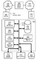
도 11은 본 발명의 일 실시예가 구현될 수 있는 칩 셋(1100)을 예시한다. 칩 셋(1100)은 본원에서 설명된 방법의 하나 이상의 단계들을 수행하도록 프로그래밍되며, 예를 들어, 하나 이상의 물리적 패키지들(예를 들어, 칩들) 내에 통합된 도 10과 관련하여 설명된 프로세서 및 메모리 컴포넌트들을 포함한다. 예로서, 물리적 패키지는, 물리적 강도, 크기의 보존, 및/또는 전기적 상호작용의 제한과 같은 하나 이상의 특성들을 제공하기 위해 구조적 어셈블리(예를 들어, 베이스보드) 상에 하나 이상의 재료들, 컴포넌트들, 및/또는 와이어들의 배열을 포함한다. 특정 실시예들에 있어서, 칩 셋은 단일 칩 내에 구현될 수 있음이 고려된다. 칩 셋(1100) 또는 이의 일 부분은 본원에서 설명되는 하나 이상의 방법들의 하나 이상의 단계들을 수행하기 위한 수단을 구성한다.11 illustrates a
일 실시예에 있어서, 칩 셋(1100)은 칩 셋(1100)의 컴포넌트들 사이에서 정보를 전달하기 위한 버스(1101)와 같은 통신 메커니즘을 포함한다. 프로세서(1103)는, 예를 들어, 메모리(1105)에 저장된 정보를 프로세싱하고 명령어들을 실행하기 위해 버스(1101)에 대한 연결성을 갖는다. 프로세서(1103)는 각각의 코어가 독립적으로 수행하도록 구성된 상태로 하나 이상의 프로세싱 코어들을 포함할 수 있다. 멀티-코어 프로세서는 단일의 물리적 패키지 내에서의 멀티프로세싱을 가능하게 한다. 멀티-코어 프로세서의 예들은 2개, 4개, 8개, 또는 더 큰 수의 프로세싱 코어들을 포함한다. 대안적으로 또는 추가적으로, 프로세서(1103)는, 명령어들의 독립 실행, 파이프라이닝(pipelining), 및 멀티스레딩(multithreading)을 가능하게 하기 위해 버스(1101)를 통해 직렬(tandem)로 구성된 하나 이상의 마이크로프로세서들을 포함할 수 있다. 프로세서(1103)에는 또한 하나 이상의 디지털 신호 프로세서(digital signal processor; DSP)들(1107) 또는 하나 이상의 애플리케이션-특정 집적 회로(ASIC)들(1109)과 같은 특정 프로세싱 기능들 및 임무들을 수행하기 위한 하나 이상의 특수 컴포넌트들이 부수될 수 있다. DSP(1107)는 전형적으로 프로세서(1103)와는 독립적으로 실시간으로 현실 신호들(예를 들어, 사운드)을 프로세싱하도록 구성된다. 유사하게, ASIC(1109)은 범용 프로세서에 의해 용이하게 수행되지 않는 특수 기능들을 수행하도록 구성될 수 있다. 본원에서 설명된 진보적인 기능들을 수행하는데 도움을 주기 위한 다른 특수 컴포넌트들은 하나 이상의 필드 프로그램가능 게이트 어레이(FPGA)들(미도시), 하나 이상의 제어기들(미도시), 하나 이상의 다른 특수-목적 컴퓨터 칩들을 포함한다. In one embodiment, the
프로세서(1103) 및 부수 컴포넌트들은 버스(1101)를 통해 메모리(1105)에 대한 연결성을 갖는다. 메모리(1105)는, 실행될 때 본원에서 설명된 방법의 하나 이상의 단계들을 수행하는 실행가능 명령어들을 저장하기 위한 정적 메모리(예를 들어, ROM, CD-ROM, 등) 및 동적 메모리(예를 들어, RAM, 자기 디스크, 기입가능 광 디스크, 등) 둘 모두를 포함한다. 메모리(1105)는 또한 본원에서 설명되는 방법들의 하나 이상의 단계들의 실행에 의해 생성되거나 또는 이와 연관된 데이터를 저장한다.
4. 변경들, 확장들 및 수정들 4. Changes, extensions and modifications
전술한 명세서에서, 본 발명은 그것의 특정 실시예들을 참조하여 설명되었다. 그러나, 본 발명의 광범위한 사상 및 범위로부터 벗어나지 않고 이에 대한 다양한 수정들 및 변화들이 이루이질 수 있다는 것이 명백할 것이다. 따라서, 본 명세서 및 도면들은 제한적인 의미가 아니라 예시적인 것으로서 간주되어야 한다. 본 명세서 및 청구항들 전체에 걸쳐, 문맥이 달리 요구하지 않는 한, 단어 "포함한다" 및 "포함하는" 및 "포함하며"와 같은 그 변형어들은 언급된 아이템, 아이템들의 엘리먼트 또는 단계 또는 그룹, 엘리먼트들 또는 단계들을 포함하지만 임의의 다른 아이템, 아이템들의 엘리먼트 또는 단계 또는 그룹, 엘리먼트들 또는 단계들을 배제하지 않는 것을 의미하는 것으로서 이해될 것이다. 또한, 부정 관사 "a" 또는 "an"은 관사에 의해 수식되는 아이템, 엘리먼트 또는 단계 중 하나 이상을 나타내는 것으로 여겨진다. 본원에서 사용될 때, 문맥으로부터 달리 명백하지 않는 한, 이것이 다른 값의 2의 인자(2배 또는 절반) 내에 있는 경우 값은 "약" 다른 값이다. 예시적인 범위들이 주어지지만, 문맥으로부터 달리 명백하지 않는 한, 임의의 포함된 범위들이 또한 다양한 실시예들에서 의도된다. 따라서, 0 내지 10의 범위는 일부 실시예들에서 1 내지 4의 범위를 포함한다. In the foregoing specification, the invention has been described with reference to its specific embodiments. However, it will be apparent that various modifications and changes can be made thereto without departing from the broad spirit and scope of the invention. Accordingly, the specification and drawings are to be regarded as illustrative rather than restrictive. Throughout this specification and claims, unless the context requires otherwise, the words “comprises” and variations thereof such as “comprising” and “comprising” refer to the item, element or step or group of items, It will be understood as meaning that it includes elements or steps but does not exclude any other item, element or step or group of elements, elements or steps. Also, the indefinite article "a" or "an" is considered to represent one or more of the items, elements or steps modified by the article. As used herein, unless stated otherwise from the context, a value is “about” another value if it is within a factor of 2 (2 or half) of the other value. Exemplary ranges are given, but any included ranges are also intended in various embodiments, unless otherwise apparent from the context. Accordingly, a range of 0 to 10 includes a range of 1 to 4 in some embodiments.
5. 참고 문헌들 5. References
Adany, P., C. Allen, 및 R. Hui, “Chirped Lidar Using Simplified Homodyne Detection”, Jour. Lightwave Tech., v. 27 (16), 2009년 08월 15일.Adany, P., C. Allen, and R. Hui, “Chirped Lidar Using Simplified Homodyne Detection,” Jour. Lightwave Tech., V. 27 (16), August 15, 2009.
Hui, R., C. Allen, 및 P. Adany, “Coherent detection scheme for FM Chirped laser RADAR”, 미국 특허 7,742,152, 2010년, 06월 22일.Hui, R., C. Allen, and P. Adany, “Coherent detection scheme for FM Chirped laser RADAR”, US Patent 7,742,152, June 22, 2010.
Kachelmyer, A.L., “Range-Doppler Imaging with a Laser Radar,” The Lincoln Laboratory Journal, v. 3. (1), 1990년.Kachelmyer, A.L., “Range-Doppler Imaging with a Laser Radar,” The Lincoln Laboratory Journal, v. 3. (1), 1990.
Claims (21)
광학적 신호를 방출하기 위한 레이저 소스;
입력 디지털 처프(chirp) 신호를 생성하기 위한 RF 파형 생성기로서, 상기 입력 디지털 처프 신호는 사각파 디지털 처프 신호에 기초하는, 상기 RF 파형 생성기;
상기 입력 디지털 처프 신호에 기초하여 상기 광학적 신호의 주파수를 변조하기 위한 변조기;
상기 광학적 신호를 송신 광학적 신호 및 기준 광학적 신호로 분할하기 위한 스플리터(splitter);
물체에 부딪혀 후방으로 산란되는 상기 송신 광학적 신호에 기초하는 복귀 광학적 신호와 상기 기준 광학적 신호를 결합하기 위한 검출기로서, 상기 검출기는 상기 결합된 기준 광학적 신호 및 상기 복귀 광학적 신호에 기초하여 전기적 출력 신호를 생성하도록 구성되는, 상기 검출기; 및
상기 전기적 출력 신호의 푸리에 변환의 특성에 기초하여 상기 물체까지의 거리(range)를 결정하기 위한 프로세서를 포함하는, 장치.
As a device,
A laser source for emitting an optical signal;
An RF waveform generator for generating an input digital chirp signal, wherein the input digital chirp signal is based on a square wave digital chirp signal;
A modulator for modulating the frequency of the optical signal based on the input digital chirp signal;
A splitter for dividing the optical signal into a transmission optical signal and a reference optical signal;
A detector for combining the reference optical signal with a return optical signal based on the transmitted optical signal that is scattered backward by striking an object, the detector receiving an electrical output signal based on the combined reference optical signal and the return optical signal. The detector, configured to generate; And
And a processor for determining a range to the object based on a characteristic of the Fourier transform of the electrical output signal.
상기 사각파 디지털 처프 신호를 생성하도록 구성된 트랜시버(transceiver)를 포함하는 필드 프로그램가능 게이트 어레이(Field Programmable Gate Array; FPGA); 및
상기 대역폭 외부의 주파수들의 범위를 상기 사각파 디지털 처프 신호의 주파수 스펙트럼으로부터 제거하도록 구성된 필터를 포함하는, 장치.
The method according to claim 1, wherein the input digital chirp signal has a bandwidth from the first frequency to the second frequency, the RF waveform generator,
A Field Programmable Gate Array (FPGA) comprising a transceiver configured to generate the square wave digital chirp signal; And
And a filter configured to remove a range of frequencies outside the bandwidth from the frequency spectrum of the square wave digital chirp signal.
3. The apparatus of claim 2, wherein the RF waveform generator further comprises an equalizer configured to flatten the amplitude of the frequency spectrum over the bandwidth.
The method according to claim 1, wherein the RF waveform generator is further configured to generate a second input digital chirp signal based on the second square wave digital signal, and the device is configured to generate the reference optical signal based on the second input digital chirp signal. And further comprising a phase modulator for modulating the phase.
5. The RF waveform generator of claim 4, wherein the RF waveform generator comprises a field programmable gate array (FPGA) having a transceiver having a first channel and a second channel, the first channel to transmit the input digital chirp signal to the modulator. And wherein the second channel is configured to transmit the second input digital chirp signal to the phase modulator.
레이저 소스로부터 광학적 신호를 방출하는 단계;
RF 파형 생성기로부터의 입력 디지털 처프 신호에 기초하여 변조기를 가지고 상기 광학적 신호의 주파수를 변조하는 단계로서, 상기 입력 디지털 처프 신호는 사각파 디지털 처프 신호에 기초하는, 단계;
스플리터를 가지고 상기 광학적 신호를 송신 광학적 신호 및 기준 광학적 신호로 분할하는 단계;
검출기에서 상기 기준 광학적 신호와 복귀 광학적 신호를 결합하는 단계로서, 상기 복귀 광학적 신호는 물체에 부딪혀 후방으로 산란된 상기 송신 광학적 신호에 기초하는, 단계;
상기 검출기를 가지고, 상기 결합하는 단계에 기초하여 전기적 출력 신호를 생성하는 단계;
프로세서를 가지고, 상기 전기적 출력 신호의 푸리에 변환의 특성에 기초하여 상기 물체까지의 거리를 결정하는 단계를 포함하는, 방법.
As a method,
Emitting an optical signal from the laser source;
Modulating a frequency of the optical signal with a modulator based on an input digital chirp signal from an RF waveform generator, the input digital chirp signal being based on a square wave digital chirp signal;
Dividing the optical signal into a transmission optical signal and a reference optical signal with a splitter;
Combining the reference optical signal and a return optical signal at a detector, wherein the return optical signal is based on the transmitted optical signal scattered backward by hitting an object;
Generating an electrical output signal based on the combining with the detector;
And with a processor, determining a distance to the object based on a characteristic of the Fourier transform of the electrical output signal.
The method according to claim 6, wherein the input digital chirp signal is the square wave digital chirp signal.
The method of claim 6, wherein the RF waveform generator comprises a field programmable gate array (FPGA).
상기 RF 파형 생성기의 트랜시버를 가지고, 상기 사각파 디지털 처프 신호를 생성하는 단계;
상기 사각파 디지털 처프 신호의 주파수 스펙트럼을 결정하는 단계; 및
상기 RF 파형 생성기의 필터를 가지고, 상기 대역폭 외부의 주파수들의 범위를 상기 주파수 스펙트럼으로부터 제거하는 단계를 포함하는, 방법.
The method according to claim 6, wherein the input digital chirp signal has a bandwidth from a first frequency to a second frequency, the method includes the step of forming the input digital chirp signal with the RF waveform generator, Forming the digital chirp signal,
Generating the square wave digital chirp signal with the transceiver of the RF waveform generator;
Determining a frequency spectrum of the square wave digital chirp signal; And
And with the filter of the RF waveform generator, removing a range of frequencies outside the bandwidth from the frequency spectrum.
10. The method of claim 9, wherein the frequency spectrum is a frequency power spectrum, and removing the range of frequencies establishes a minimum dynamic range between the amplitude of the frequency power spectrum within the bandwidth and the amplitude of the frequency power spectrum outside the bandwidth. The method comprising the step of.
The method of claim 10, wherein the minimum dynamic range is at least 20 dB.
10. The method of claim 9, wherein generating the input digital chirp signal comprises: flattening an amplitude of the frequency spectrum over the bandwidth from the first frequency to the second frequency with an equalizer of the RF waveform generator; The method, which further includes.
10. The method of claim 9, wherein the transceiver is a transceiver of a field programmable gate array (FPGA).
The method of claim 9, wherein the bandwidth is in a range of about 10 GHz to about 30 GHz.
상기 사각파 디지털 처프 신호의 주파수 스펙트럼을 결정하는 단계; 및
상기 RF 파형 생성기의 이퀄라이저를 가지고, 상기 제 1 주파수로부터 상기 제 2 주파수까지의 상기 대역폭에 걸쳐 상기 주파수 스펙트럼의 진폭을 평탄화하는 단계를 포함하는, 방법.
The method according to claim 6, wherein the input digital chirp signal has a bandwidth from a first frequency to a second frequency, the method includes the step of generating the input digital chirp signal with the RF waveform generator, The step of generating a digital chirp signal is,
Determining a frequency spectrum of the square wave digital chirp signal; And
And flattening the amplitude of the frequency spectrum over the bandwidth from the first frequency to the second frequency with an equalizer of the RF waveform generator.
상기 RF 파형 생성기의 상기 트랜시버를 가지고, 상기 사각파 디지털 처프의 제 1 수의 클럭 사이클들에 걸쳐 제 1 주파수를 출력하기 위해 상기 제 1 수의 클럭 사이클들에 걸쳐 고정된 진폭 신호를 출력하는 단계; 및
상기 RF 파형 생성기의 상기 트랜시버를 가지고, 상기 사각파 디지털 처프의 제 2 수의 클럭 사이클들에 걸쳐 제 1 주파수와는 상이한 제 2 주파수를 출력하기 위해 상기 제 1 수의 클럭 사이클들과는 상이한 상기 제 2 수의 클럭 사이클들에 걸쳐 고정된 진폭 신호를 출력하는 단계를 포함하는, 방법.
The method of claim 9, wherein the step of generating the square wave digital chirp signal,
Outputting a fixed amplitude signal over the first number of clock cycles to output a first frequency over the first number of clock cycles of the square wave digital chirp with the transceiver of the RF waveform generator; ; And
The second different from the first number of clock cycles to output a second frequency different from the first frequency over the second number of clock cycles of the square wave digital chirp with the transceiver of the RF waveform generator And outputting a fixed amplitude signal over a number of clock cycles.
17. The method of claim 16, wherein the method comprises: uploading a plurality of instructions into the memory of the transceiver, the plurality of instructions being the fixed amplitude signal and the second number to be output over the first number of clock cycles. And including data representing the fixed amplitude signal to be output over clock cycles of the method.
7. The method of claim 6, wherein the method comprises modulating the phase of the reference optical signal with a phase modulator based on a second input digital chirp signal from the RF waveform generator, wherein the second input digital chirp signal is a second And further comprising a step based on the square wave digital chirp signal.
The frequency of the transmission optical signal is modulated based on the input digital chirp signal from the first channel of the RF waveform generator, and the phase of the reference optical signal is from the second channel of the RF waveform generator. And modulated based on the second input digital chirp signal.
20. The method of claim 19, wherein the second input digital chirp signal from the second channel is the input digital chirp signal from the first channel.
Priority Applications (1)
| Application Number | Priority Date | Filing Date | Title |
|---|---|---|---|
| KR1020217040580A KR102454659B1 (en) | 2017-07-27 | 2018-07-27 | Method and system for using square wave digital chirp signal for optical chirped range detection |
Applications Claiming Priority (3)
| Application Number | Priority Date | Filing Date | Title |
|---|---|---|---|
| US15/661,377 | 2017-07-27 | ||
| US15/661,377 US10534084B2 (en) | 2017-07-27 | 2017-07-27 | Method and system for using square wave digital chirp signal for optical chirped range detection |
| PCT/US2018/044007 WO2019023529A1 (en) | 2017-07-27 | 2018-07-27 | Method and system for using square wave digital chirp signal for optical chirped range detection |
Related Child Applications (1)
| Application Number | Title | Priority Date | Filing Date |
|---|---|---|---|
| KR1020217040580A Division KR102454659B1 (en) | 2017-07-27 | 2018-07-27 | Method and system for using square wave digital chirp signal for optical chirped range detection |
Publications (2)
| Publication Number | Publication Date |
|---|---|
| KR20200037148A true KR20200037148A (en) | 2020-04-08 |
| KR102340050B1 KR102340050B1 (en) | 2021-12-15 |
Family
ID=65037849
Family Applications (2)
| Application Number | Title | Priority Date | Filing Date |
|---|---|---|---|
| KR1020197038797A KR102340050B1 (en) | 2017-07-27 | 2018-07-27 | Method and system for using square wave digital chirped signal for optically chirped distance detection |
| KR1020217040580A KR102454659B1 (en) | 2017-07-27 | 2018-07-27 | Method and system for using square wave digital chirp signal for optical chirped range detection |
Family Applications After (1)
| Application Number | Title | Priority Date | Filing Date |
|---|---|---|---|
| KR1020217040580A KR102454659B1 (en) | 2017-07-27 | 2018-07-27 | Method and system for using square wave digital chirp signal for optical chirped range detection |
Country Status (6)
| Country | Link |
|---|---|
| US (3) | US10534084B2 (en) |
| EP (1) | EP3658952A4 (en) |
| JP (2) | JP6945262B2 (en) |
| KR (2) | KR102340050B1 (en) |
| CN (2) | CN117890921A (en) |
| WO (1) | WO2019023529A1 (en) |
Cited By (2)
| Publication number | Priority date | Publication date | Assignee | Title |
|---|---|---|---|---|
| KR20220083622A (en) * | 2020-12-11 | 2022-06-20 | 셈테크 코포레이션 | Doppler ranging system |
| WO2023108199A1 (en) * | 2021-12-17 | 2023-06-22 | Baraja Pty Ltd | Spatial estimation systems including homodyne optical receivers |
Families Citing this family (25)
| Publication number | Priority date | Publication date | Assignee | Title |
|---|---|---|---|---|
| US10217057B2 (en) * | 2015-10-29 | 2019-02-26 | Google Llc | Removing leakage in a quantum bit |
| DE102016215173A1 (en) * | 2016-08-15 | 2018-02-15 | Leoni Kabel Gmbh | Method for monitoring a line for changed ambient conditions and measuring arrangement for monitoring a line for changed ambient conditions |
| EP3548840B1 (en) | 2016-11-29 | 2023-10-11 | Blackmore Sensors & Analytics, LLC | Method and system for classification of an object in a point cloud data set |
| EP3548926A4 (en) | 2016-11-30 | 2020-07-01 | Blackmore Sensors And Analytics Inc. | Method and system for adaptive scanning with optical ranging systems |
| EP3548925A4 (en) | 2016-11-30 | 2020-07-01 | Blackmore Sensors And Analytics Inc. | Method and system for automatic real-time adaptive scanning with optical ranging systems |
| WO2018160240A2 (en) | 2016-11-30 | 2018-09-07 | Blackmore Sensors and Analytics Inc. | Method and system for doppler detection and doppler correction of optical chirped range detection |
| US10422880B2 (en) | 2017-02-03 | 2019-09-24 | Blackmore Sensors and Analytics Inc. | Method and system for doppler detection and doppler correction of optical phase-encoded range detection |
| US10401495B2 (en) | 2017-07-10 | 2019-09-03 | Blackmore Sensors and Analytics Inc. | Method and system for time separated quadrature detection of doppler effects in optical range measurements |
| JP6991034B2 (en) * | 2017-10-19 | 2022-01-12 | 株式会社トプコン | Method for determining modulation frequency of light wave rangefinder and feedback signal |
| CN112154347B (en) | 2018-04-23 | 2022-05-10 | 布莱克莫尔传感器和分析有限责任公司 | Method and system for controlling autonomous vehicle using coherent range-doppler optical sensor |
| JP6970648B2 (en) * | 2018-08-27 | 2021-11-24 | 株式会社東芝 | Electronic device and distance measurement method |
| US11822010B2 (en) | 2019-01-04 | 2023-11-21 | Blackmore Sensors & Analytics, Llc | LIDAR system |
| WO2020155092A1 (en) * | 2019-02-01 | 2020-08-06 | Boe Technology Group Co., Ltd. | Apparatus integrated with display panel for tof 3d spatial positioning |
| US10838061B1 (en) * | 2019-07-16 | 2020-11-17 | Blackmore Sensors & Analytics, LLC. | Method and system for enhanced velocity resolution and signal to noise ratio in optical phase-encoded range detection |
| US11754711B2 (en) | 2019-12-31 | 2023-09-12 | Luminar Technologies, Inc. | Frequency chirp for lidar for high-velocity targets |
| US10880014B1 (en) * | 2020-01-03 | 2020-12-29 | Cisco Technology, Inc. | Active relative intensity noise mitigation using nested interferometers, and trans-impedance amplifier |
| CN112666531B (en) * | 2020-12-21 | 2022-10-18 | 上海无线电设备研究所 | Distance Doppler coupling effect evaluation method and system based on constant acceleration |
| CN113504513B (en) * | 2021-06-30 | 2023-05-23 | 电子科技大学 | Time domain nonlinear frequency modulation signal generation method |
| US11874404B2 (en) | 2021-07-14 | 2024-01-16 | Voyant Photonics, Inc. | Multi-chirp pre-distorted laser linearization for FMCW LiDAR |
| US20230104453A1 (en) * | 2021-10-05 | 2023-04-06 | Silc Technologies, Inc. | Increasing rate of lidar measurements |
| WO2023092396A1 (en) * | 2021-11-25 | 2023-06-01 | Huawei Technologies Co., Ltd. | Method and apparatus for signaling for beam management using chirp beams |
| US20230204749A1 (en) * | 2021-12-23 | 2023-06-29 | Gm Cruise Holdings Llc | Radar sensor processing chain |
| US20230243977A1 (en) * | 2022-02-03 | 2023-08-03 | Blackmore Sensors & Analytics, LLC. | Lidar system |
| CN114690196B (en) * | 2022-05-31 | 2022-08-26 | 杭州蓝芯科技有限公司 | Light double-chirp distance measuring radar system |
| CN116540250B (en) * | 2023-05-19 | 2024-04-05 | 深圳光谦传感科技有限公司 | Laser ranging method and system |
Citations (6)
| Publication number | Priority date | Publication date | Assignee | Title |
|---|---|---|---|---|
| JPH0954157A (en) * | 1995-08-14 | 1997-02-25 | Topcon Corp | Distance-measuring apparatus |
| US20040109155A1 (en) * | 2002-05-29 | 2004-06-10 | Deines Kent L. | System and method for measuring velocity using frequency modulation of laser output |
| KR20060059741A (en) * | 2004-11-29 | 2006-06-02 | 삼성전기주식회사 | Apparatus for transmitting digital data using saw filter |
| US20080018881A1 (en) * | 2006-06-23 | 2008-01-24 | Rongqing Hui | Coherent Detection Scheme For FM Chirped Laser Radar |
| CN105652282A (en) * | 2015-12-29 | 2016-06-08 | 电子科技大学 | Laser phase ranging module |
| JP2017075786A (en) * | 2015-10-13 | 2017-04-20 | 国立研究開発法人情報通信研究機構 | Radar device including ultra-wideband signal source |
Family Cites Families (55)
| Publication number | Priority date | Publication date | Assignee | Title |
|---|---|---|---|---|
| US1003681A (en) | 1908-07-29 | 1911-09-19 | Rinaldo Williams | Process of making superphosphate. |
| US4099249A (en) | 1977-02-22 | 1978-07-04 | The United States Of America As Represented By The Secretary Of The Navy | Doppler processing method and apparatus |
| US4648276A (en) * | 1984-01-27 | 1987-03-10 | Klepper John R | Apparatus for measuring the characteristics of an ultrasonic wave medium |
| US5170218A (en) * | 1991-03-29 | 1992-12-08 | Raytheon Company | Apparatus and method for detecting wind direction |
| US5874914A (en) | 1995-10-09 | 1999-02-23 | Snaptrack, Inc. | GPS receiver utilizing a communication link |
| US5877851A (en) * | 1997-09-24 | 1999-03-02 | The United States Of America As Represented By The Secretary Of The Army | Scannerless ladar architecture employing focal plane detector arrays and FM-CW ranging theory |
| JP2001007873A (en) * | 1999-06-25 | 2001-01-12 | Hitachi Ltd | Transmitter for digital frequency modulation |
| DE60009565T2 (en) | 2000-01-26 | 2005-02-24 | Instro Precision Ltd., Broadstairs | OPTICAL DISTANCE MEASUREMENT |
| US6931055B1 (en) | 2000-04-18 | 2005-08-16 | Sirf Technology, Inc. | Signal detector employing a doppler phase correction system |
| US20020071109A1 (en) | 2000-07-24 | 2002-06-13 | Christopher Allen | Laser radar system and method |
| JP2002162465A (en) * | 2000-11-24 | 2002-06-07 | Nippon Telegr & Teleph Corp <Ntt> | Radar device |
| US7697748B2 (en) | 2004-07-06 | 2010-04-13 | Dimsdale Engineering, Llc | Method and apparatus for high resolution 3D imaging as a function of camera position, camera trajectory and range |
| EP1645890A1 (en) * | 2004-10-09 | 2006-04-12 | Leica Geosystems AG | Method for measuring distances including the determination of the non-ideal characteristics of the chirp |
| EP2386245B1 (en) | 2005-02-14 | 2012-12-19 | Digital Signal Corporation | Laser radar system for providing chirped electromagnetic radiation |
| US8488967B2 (en) | 2005-02-18 | 2013-07-16 | Telcordia Technologies, Inc. | System and method for OCDMA-based photonic layer security robustness to archival attack |
| US20060239312A1 (en) | 2005-04-23 | 2006-10-26 | Telaris Inc. | Semiconductor Lasers in Optical Phase-Locked Loops |
| US7345744B2 (en) * | 2005-06-06 | 2008-03-18 | Raytheon Company | Optical delay line to correct phase errors in coherent ladar |
| US7215413B2 (en) * | 2005-06-24 | 2007-05-08 | The Boeing Company | Chirped synthetic wave laser radar apparatus and methods |
| US7917039B1 (en) | 2007-02-09 | 2011-03-29 | University Of Central Florida Research Foundation, Inc. | Signal processing using spectrally phase-encoded optical frequency combs |
| US7573564B2 (en) | 2007-06-26 | 2009-08-11 | The United States Of America As Represented By The Secretary Of The Army | Systems for doppler tracking using photonic mixing detectors |
| CN101089653B (en) * | 2007-07-20 | 2011-03-09 | 西安理工大学 | Short-range frequency-modulation continuous wave FMCW radar anti-interference method |
| US7746450B2 (en) * | 2007-08-28 | 2010-06-29 | Science Applications International Corporation | Full-field light detection and ranging imaging system |
| EP2128561B1 (en) * | 2008-05-28 | 2014-10-29 | Leica Geosystems AG | Interferometric distance measuring method with delayed chirp signal and such a device |
| WO2010006081A1 (en) | 2008-07-08 | 2010-01-14 | Chiaro Technologies, Inc. | Multiple channel locating |
| WO2010030884A2 (en) | 2008-09-11 | 2010-03-18 | Metris Usa, Inc. | Compact fiber optic geometry for a counter chirp fmcw coherent laser radar |
| US8467749B2 (en) * | 2008-10-16 | 2013-06-18 | Texas Instruments Incorporated | Monolithic FM-band transmit power amplifier for mobile cellular devices and method of operation thereof |
| EP2425506A2 (en) | 2009-04-29 | 2012-03-07 | Montana State University | Precise broadband frequency modulated laser |
| CA2800267C (en) | 2010-05-28 | 2018-08-07 | Optical Air Data Systems, Llc | Method and apparatus for a pulsed coherent laser range finder |
| US9229106B2 (en) | 2010-08-13 | 2016-01-05 | Ryan Dotson | Enhancement of range measurement resolution using imagery |
| US20120274922A1 (en) | 2011-03-28 | 2012-11-01 | Bruce Hodge | Lidar methods and apparatus |
| US8537376B2 (en) * | 2011-04-15 | 2013-09-17 | Faro Technologies, Inc. | Enhanced position detector in laser tracker |
| CN102565769B (en) | 2011-12-30 | 2014-06-04 | 陕西延长石油(集团)有限责任公司研究院 | Error compensation method for ground penetrating radar system |
| US9383753B1 (en) | 2012-09-26 | 2016-07-05 | Google Inc. | Wide-view LIDAR with areas of special attention |
| KR101357120B1 (en) * | 2013-04-23 | 2014-02-05 | 김태민 | Method of measuring distance based on optical signals and apparatuse thereof |
| EP2806286B1 (en) | 2013-05-23 | 2019-07-10 | Veoneer Sweden AB | FMCW radar blocking detection |
| US9683928B2 (en) | 2013-06-23 | 2017-06-20 | Eric Swanson | Integrated optical system and components utilizing tunable optical sources and coherent detection and phased array for imaging, ranging, sensing, communications and other applications |
| US9683836B2 (en) | 2013-08-09 | 2017-06-20 | Conduent Business Services, Llc | Vehicle classification from laser scanners using fisher and profile signatures |
| JP6146295B2 (en) | 2013-12-26 | 2017-06-14 | 株式会社豊田中央研究所 | Radar apparatus and speed direction measuring method |
| US9383442B2 (en) | 2014-05-12 | 2016-07-05 | Autoliv Asp, Inc. | Radar system and method for determining range, relative velocity and bearing of an object using continuous-wave and chirp signals |
| WO2016069744A1 (en) | 2014-10-29 | 2016-05-06 | Bridger Photonics, Inc. | Accurate chirped synthetic wavelength interferometer |
| JP6520053B2 (en) * | 2014-11-06 | 2019-05-29 | 株式会社デンソー | Optical flight type distance measuring device |
| US10001548B2 (en) | 2015-01-23 | 2018-06-19 | Navico Holding As | Amplitude envelope correction |
| US10036812B2 (en) | 2015-06-24 | 2018-07-31 | Blackmore Sensors and Analytics Inc. | Method and system for three dimensional digital holographic aperture synthesis |
| JP2017125717A (en) | 2016-01-12 | 2017-07-20 | セイコーエプソン株式会社 | Distance meter |
| US10416292B2 (en) | 2016-05-24 | 2019-09-17 | Veoneer Us, Inc. | Direct detection LiDAR system and method with frequency modulation (FM) transmitter and quadrature receiver |
| US10330778B2 (en) | 2016-06-03 | 2019-06-25 | Nokia Of America Corporation | Coherent lidar system using tunable carrier-suppressed single-sideband modulation |
| CN106195742B (en) | 2016-07-15 | 2018-07-20 | 四川蓝景光电技术有限责任公司 | Silica gel extrusion molding dispensing LED neon lamp belt processing technologys based on FPC |
| WO2018067158A1 (en) * | 2016-10-06 | 2018-04-12 | Strobe, Inc. | Lidar system |
| EP3548840B1 (en) | 2016-11-29 | 2023-10-11 | Blackmore Sensors & Analytics, LLC | Method and system for classification of an object in a point cloud data set |
| EP3548926A4 (en) | 2016-11-30 | 2020-07-01 | Blackmore Sensors And Analytics Inc. | Method and system for adaptive scanning with optical ranging systems |
| EP3548925A4 (en) | 2016-11-30 | 2020-07-01 | Blackmore Sensors And Analytics Inc. | Method and system for automatic real-time adaptive scanning with optical ranging systems |
| WO2018160240A2 (en) | 2016-11-30 | 2018-09-07 | Blackmore Sensors and Analytics Inc. | Method and system for doppler detection and doppler correction of optical chirped range detection |
| CN106707291B (en) * | 2016-12-09 | 2020-01-03 | 中国科学技术大学 | Double-frequency linear frequency modulation coherent wind lidar |
| US11162789B2 (en) | 2016-12-16 | 2021-11-02 | Baraja Pty Ltd | Estimation of spatial profile of environment |
| US10422880B2 (en) | 2017-02-03 | 2019-09-24 | Blackmore Sensors and Analytics Inc. | Method and system for doppler detection and doppler correction of optical phase-encoded range detection |
-
2017
- 2017-07-27 US US15/661,377 patent/US10534084B2/en active Active
-
2018
- 2018-07-27 CN CN202311760816.XA patent/CN117890921A/en active Pending
- 2018-07-27 CN CN201880044454.5A patent/CN110869798B/en active Active
- 2018-07-27 WO PCT/US2018/044007 patent/WO2019023529A1/en active Application Filing
- 2018-07-27 JP JP2019571343A patent/JP6945262B2/en active Active
- 2018-07-27 EP EP18839276.5A patent/EP3658952A4/en active Pending
- 2018-07-27 KR KR1020197038797A patent/KR102340050B1/en active IP Right Grant
- 2018-07-27 KR KR1020217040580A patent/KR102454659B1/en active IP Right Grant
-
2019
- 2019-12-18 US US16/719,010 patent/US10670720B2/en active Active
-
2020
- 2020-04-28 US US16/860,470 patent/US11579292B2/en active Active
-
2021
- 2021-09-10 JP JP2021147661A patent/JP7317910B2/en active Active
Patent Citations (6)
| Publication number | Priority date | Publication date | Assignee | Title |
|---|---|---|---|---|
| JPH0954157A (en) * | 1995-08-14 | 1997-02-25 | Topcon Corp | Distance-measuring apparatus |
| US20040109155A1 (en) * | 2002-05-29 | 2004-06-10 | Deines Kent L. | System and method for measuring velocity using frequency modulation of laser output |
| KR20060059741A (en) * | 2004-11-29 | 2006-06-02 | 삼성전기주식회사 | Apparatus for transmitting digital data using saw filter |
| US20080018881A1 (en) * | 2006-06-23 | 2008-01-24 | Rongqing Hui | Coherent Detection Scheme For FM Chirped Laser Radar |
| JP2017075786A (en) * | 2015-10-13 | 2017-04-20 | 国立研究開発法人情報通信研究機構 | Radar device including ultra-wideband signal source |
| CN105652282A (en) * | 2015-12-29 | 2016-06-08 | 电子科技大学 | Laser phase ranging module |
Cited By (2)
| Publication number | Priority date | Publication date | Assignee | Title |
|---|---|---|---|---|
| KR20220083622A (en) * | 2020-12-11 | 2022-06-20 | 셈테크 코포레이션 | Doppler ranging system |
| WO2023108199A1 (en) * | 2021-12-17 | 2023-06-22 | Baraja Pty Ltd | Spatial estimation systems including homodyne optical receivers |
Also Published As
| Publication number | Publication date |
|---|---|
| KR20210153766A (en) | 2021-12-17 |
| JP6945262B2 (en) | 2021-10-06 |
| CN110869798B (en) | 2023-12-22 |
| US20200124727A1 (en) | 2020-04-23 |
| JP7317910B2 (en) | 2023-07-31 |
| US20190033453A1 (en) | 2019-01-31 |
| EP3658952A4 (en) | 2021-03-10 |
| US11579292B2 (en) | 2023-02-14 |
| CN110869798A (en) | 2020-03-06 |
| US10670720B2 (en) | 2020-06-02 |
| KR102340050B1 (en) | 2021-12-15 |
| CN117890921A (en) | 2024-04-16 |
| WO2019023529A1 (en) | 2019-01-31 |
| US10534084B2 (en) | 2020-01-14 |
| KR102454659B1 (en) | 2022-10-13 |
| US20200256994A1 (en) | 2020-08-13 |
| JP2020534510A (en) | 2020-11-26 |
| EP3658952A1 (en) | 2020-06-03 |
| JP2021192054A (en) | 2021-12-16 |
Similar Documents
| Publication | Publication Date | Title |
|---|---|---|
| KR102340050B1 (en) | Method and system for using square wave digital chirped signal for optically chirped distance detection | |
| KR102379447B1 (en) | Lidar system to adjust doppler effects | |
| KR102254468B1 (en) | Method and apparatus for Doppler detection and Doppler correction of optical chirp distance detection | |
| KR102391143B1 (en) | Method and system for laser phase tracking for internal reflection subtraction in phase encoded lidar | |
| JP2022003345A5 (en) | ||
| US20220244363A1 (en) | Method and system for sidelobe suppression in phase encoded doppler lidar | |
| US11630189B2 (en) | Multi-tone continuous wave detection and ranging |
Legal Events
| Date | Code | Title | Description |
|---|---|---|---|
| N231 | Notification of change of applicant | ||
| E902 | Notification of reason for refusal | ||
| E902 | Notification of reason for refusal | ||
| E701 | Decision to grant or registration of patent right | ||
| GRNT | Written decision to grant |