KR20200034892A - Method and apparatus for determining an azimuth of a base station - Google Patents
Method and apparatus for determining an azimuth of a base station Download PDFInfo
- Publication number
- KR20200034892A KR20200034892A KR1020180114295A KR20180114295A KR20200034892A KR 20200034892 A KR20200034892 A KR 20200034892A KR 1020180114295 A KR1020180114295 A KR 1020180114295A KR 20180114295 A KR20180114295 A KR 20180114295A KR 20200034892 A KR20200034892 A KR 20200034892A
- Authority
- KR
- South Korea
- Prior art keywords
- base station
- azimuth
- antenna module
- terminal
- received signal
- Prior art date
Links
Images


Classifications
-
- G—PHYSICS
- G01—MEASURING; TESTING
- G01S—RADIO DIRECTION-FINDING; RADIO NAVIGATION; DETERMINING DISTANCE OR VELOCITY BY USE OF RADIO WAVES; LOCATING OR PRESENCE-DETECTING BY USE OF THE REFLECTION OR RERADIATION OF RADIO WAVES; ANALOGOUS ARRANGEMENTS USING OTHER WAVES
- G01S3/00—Direction-finders for determining the direction from which infrasonic, sonic, ultrasonic, or electromagnetic waves, or particle emission, not having a directional significance, are being received
- G01S3/02—Direction-finders for determining the direction from which infrasonic, sonic, ultrasonic, or electromagnetic waves, or particle emission, not having a directional significance, are being received using radio waves
- G01S3/14—Systems for determining direction or deviation from predetermined direction
- G01S3/38—Systems for determining direction or deviation from predetermined direction using adjustment of real or effective orientation of directivity characteristic of an antenna or an antenna system to give a desired condition of signal derived from that antenna or antenna system, e.g. to give a maximum or minimum signal
- G01S3/40—Systems for determining direction or deviation from predetermined direction using adjustment of real or effective orientation of directivity characteristic of an antenna or an antenna system to give a desired condition of signal derived from that antenna or antenna system, e.g. to give a maximum or minimum signal adjusting orientation of a single directivity characteristic to produce maximum or minimum signal, e.g. rotatable loop antenna or equivalent goniometer system
-
- G—PHYSICS
- G01—MEASURING; TESTING
- G01S—RADIO DIRECTION-FINDING; RADIO NAVIGATION; DETERMINING DISTANCE OR VELOCITY BY USE OF RADIO WAVES; LOCATING OR PRESENCE-DETECTING BY USE OF THE REFLECTION OR RERADIATION OF RADIO WAVES; ANALOGOUS ARRANGEMENTS USING OTHER WAVES
- G01S3/00—Direction-finders for determining the direction from which infrasonic, sonic, ultrasonic, or electromagnetic waves, or particle emission, not having a directional significance, are being received
- G01S3/02—Direction-finders for determining the direction from which infrasonic, sonic, ultrasonic, or electromagnetic waves, or particle emission, not having a directional significance, are being received using radio waves
- G01S3/72—Diversity systems specially adapted for direction-finding
-
- H—ELECTRICITY
- H04—ELECTRIC COMMUNICATION TECHNIQUE
- H04B—TRANSMISSION
- H04B17/00—Monitoring; Testing
- H04B17/20—Monitoring; Testing of receivers
- H04B17/24—Monitoring; Testing of receivers with feedback of measurements to the transmitter
-
- H—ELECTRICITY
- H04—ELECTRIC COMMUNICATION TECHNIQUE
- H04B—TRANSMISSION
- H04B17/00—Monitoring; Testing
- H04B17/30—Monitoring; Testing of propagation channels
- H04B17/309—Measuring or estimating channel quality parameters
- H04B17/318—Received signal strength
-
- H—ELECTRICITY
- H04—ELECTRIC COMMUNICATION TECHNIQUE
- H04W—WIRELESS COMMUNICATION NETWORKS
- H04W16/00—Network planning, e.g. coverage or traffic planning tools; Network deployment, e.g. resource partitioning or cells structures
- H04W16/24—Cell structures
- H04W16/28—Cell structures using beam steering
-
- H—ELECTRICITY
- H04—ELECTRIC COMMUNICATION TECHNIQUE
- H04B—TRANSMISSION
- H04B17/00—Monitoring; Testing
- H04B17/10—Monitoring; Testing of transmitters
- H04B17/11—Monitoring; Testing of transmitters for calibration
- H04B17/12—Monitoring; Testing of transmitters for calibration of transmit antennas, e.g. of the amplitude or phase
-
- H—ELECTRICITY
- H04—ELECTRIC COMMUNICATION TECHNIQUE
- H04B—TRANSMISSION
- H04B17/00—Monitoring; Testing
- H04B17/10—Monitoring; Testing of transmitters
- H04B17/15—Performance testing
- H04B17/17—Detection of non-compliance or faulty performance, e.g. response deviations
-
- H—ELECTRICITY
- H04—ELECTRIC COMMUNICATION TECHNIQUE
- H04B—TRANSMISSION
- H04B17/00—Monitoring; Testing
- H04B17/30—Monitoring; Testing of propagation channels
- H04B17/309—Measuring or estimating channel quality parameters
- H04B17/336—Signal-to-interference ratio [SIR] or carrier-to-interference ratio [CIR]
-
- H—ELECTRICITY
- H04—ELECTRIC COMMUNICATION TECHNIQUE
- H04W—WIRELESS COMMUNICATION NETWORKS
- H04W64/00—Locating users or terminals or network equipment for network management purposes, e.g. mobility management
- H04W64/003—Locating users or terminals or network equipment for network management purposes, e.g. mobility management locating network equipment
-
- H—ELECTRICITY
- H04—ELECTRIC COMMUNICATION TECHNIQUE
- H04W—WIRELESS COMMUNICATION NETWORKS
- H04W84/00—Network topologies
- H04W84/02—Hierarchically pre-organised networks, e.g. paging networks, cellular networks, WLAN [Wireless Local Area Network] or WLL [Wireless Local Loop]
- H04W84/04—Large scale networks; Deep hierarchical networks
- H04W84/042—Public Land Mobile systems, e.g. cellular systems
-
- H—ELECTRICITY
- H04—ELECTRIC COMMUNICATION TECHNIQUE
- H04W—WIRELESS COMMUNICATION NETWORKS
- H04W88/00—Devices specially adapted for wireless communication networks, e.g. terminals, base stations or access point devices
- H04W88/08—Access point devices
Abstract
Description
본 발명은 단말로부터 수신한 정보에 기반하여 기지국의 방위각을 결정하는 방법 및 장치를 제공한다.The present invention provides a method and apparatus for determining the azimuth angle of a base station based on information received from a terminal.
4G 통신 시스템 상용화 이후 증가 추세에 있는 무선 데이터 트래픽 수요를 충족시키기 위해, 개선된 5G 통신 시스템 또는 pre-5G 통신 시스템을 개발하기 위한 노력이 이루어지고 있다. 이러한 이유로, 5G 통신 시스템 또는 pre-5G 통신 시스템은 4G 네트워크 이후 (Beyond 4G Network) 통신 시스템 또는 LTE 시스템 이후 (Post LTE) 이후의 시스템이라 불리어지고 있다. 높은 데이터 전송률을 달성하기 위해, 5G 통신 시스템은 초고주파(mmWave) 대역 (예를 들어, 60기가(60GHz) 대역과 같은)에서의 구현이 고려되고 있다. 초고주파 대역에서의 전파의 경로손실 완화 및 전파의 전달 거리를 증가시키기 위해, 5G 통신 시스템에서는 빔포밍(beamforming), 거대 배열 다중 입출력(massive MIMO), 전차원 다중입출력(Full Dimensional MIMO: FD-MIMO), 어레이 안테나(array antenna), 아날로그 빔형성(analog beam-forming), 및 대규모 안테나 (large scale antenna) 기술들이 논의되고 있다. 또한 시스템의 네트워크 개선을 위해, 5G 통신 시스템에서는 진화된 소형 셀, 개선된 소형 셀 (advanced small cell), 클라우드 무선 액세스 네트워크 (cloud radio access network: cloud RAN), 초고밀도 네트워크 (ultra-dense network), 기기 간 통신 (Device to Device communication: D2D), 무선 백홀 (wireless backhaul), 이동 네트워크 (moving network), 협력 통신 (cooperative communication), CoMP (Coordinated Multi-Points), 및 수신 간섭제거 (interference cancellation) 등의 기술 개발이 이루어지고 있다. 이 밖에도, 5G 시스템에서는 진보된 코딩 변조(Advanced Coding Modulation: ACM) 방식인 FQAM (Hybrid FSK and QAM Modulation) 및 SWSC (Sliding Window Superposition Coding)과, 진보된 접속 기술인 FBMC(Filter Bank Multi Carrier), NOMA(non orthogonal multiple access), 및SCMA(sparse code multiple access) 등이 개발되고 있다.Efforts have been made to develop an improved 5G communication system or a pre-5G communication system to meet the increasing demand for wireless data traffic after commercialization of the 4G communication system. For this reason, the 5G communication system or the pre-5G communication system is called a 4G network (Beyond 4G Network) communication system or an LTE system (Post LTE) or later system. To achieve high data rates, 5G communication systems are being considered for implementation in the ultra-high frequency (mmWave) band (eg, 60 gigahertz (60 GHz) band). In order to mitigate the path loss of radio waves in the ultra-high frequency band and increase the transmission distance of radio waves, in 5G communication systems, beamforming, massive array multiple input / output (massive MIMO), full dimensional multiple input / output (FD-MIMO) ), Array antenna, analog beam-forming, and large scale antenna technologies are being discussed. In addition, in order to improve the network of the system, in the 5G communication system, the evolved small cell, advanced small cell, cloud radio access network (cloud RAN), ultra-dense network , Device to Device communication (D2D), wireless backhaul, mobile network, cooperative communication, CoMP (Coordinated Multi-Points), and interference cancellation Technology development is being conducted. In addition, in 5G systems, advanced coding modulation (Advanced Coding Modulation (ACM)), hybrid FSK and QAM modulation (FQAM) and sliding window superposition coding (SWSC), and advanced access technologies, FBMC (Filter Bank Multi Carrier), and NOMA (non orthogonal multiple access), and SCMA (sparse code multiple access) are being developed.
한편, 인터넷은 인간이 정보를 생성하고 소비하는 인간 중심의 연결 망에서, 사물 등 분산된 구성 요소들 간에 정보를 주고 받아 처리하는 IoT(Internet of Things, 사물인터넷) 망으로 진화하고 있다. 클라우드 서버 등과의 연결을 통한 빅데이터(Big data) 처리 기술 등이 IoT 기술에 결합된 IoE (Internet of Everything) 기술도 대두되고 있다. IoT를 구현하기 위해서, 센싱 기술, 유무선 통신 및 네트워크 인프라, 서비스 인터페이스 기술, 및 보안 기술과 같은 기술 요소 들이 요구되어, 최근에는 사물간의 연결을 위한 센서 네트워크(sensor network), 사물 통신(Machine to Machine, M2M), MTC(Machine Type Communication)등의 기술이 연구되고 있다. IoT 환경에서는 연결된 사물들에서 생성된 데이터를 수집, 분석하여 인간의 삶에 새로운 가치를 창출하는 지능형 IT(Internet Technology) 서비스가 제공될 수 있다. IoT는 기존의 IT(information technology)기술과 다양한 산업 간의 융합 및 복합을 통하여 스마트홈, 스마트 빌딩, 스마트 시티, 스마트 카 혹은 커넥티드 카, 스마트 그리드, 헬스 케어, 스마트 가전, 첨단의료서비스 등의 분야에 응용될 수 있다.Meanwhile, the Internet is evolving from a human-centered connection network in which humans generate and consume information, to an Internet of Things (IoT) network that exchanges information between distributed components such as objects. Internet of Everything (IoE) technology, in which big data processing technology, etc. through connection to a cloud server, is combined with IoT technology is also emerging. In order to implement IoT, technical elements such as sensing technology, wired / wireless communication and network infrastructure, service interface technology, and security technology are required, and recently, a sensor network for connection between objects, a machine to machine (Machine to Machine) , M2M), and MTC (Machine Type Communication). In an IoT environment, an intelligent IT (Internet Technology) service that collects and analyzes data generated from connected objects to create new values in human life may be provided. IoT is a field of smart home, smart building, smart city, smart car or connected car, smart grid, health care, smart home appliance, high-tech medical service through convergence and complex between existing IT (information technology) technology and various industries. It can be applied to.
이에, 5G 통신 시스템을 IoT 망에 적용하기 위한 다양한 시도들이 이루어지고 있다. 예를 들어, 센서 네트워크(sensor network), 사물 통신(Machine to Machine, M2M), MTC(Machine Type Communication)등의 기술이 5G 통신 기술이 빔 포밍, MIMO, 및 어레이 안테나 등의 기법에 의해 구현되고 있는 것이다. 앞서 설명한 빅데이터 처리 기술로써 클라우드 무선 액세스 네트워크(cloud RAN)가 적용되는 것도 5G 기술과 IoT 기술 융합의 일 예라고 할 수 있을 것이다.Accordingly, various attempts have been made to apply a 5G communication system to an IoT network. For example, 5G communication technology such as sensor network, machine to machine (M2M), and MTC (Machine Type Communication) is implemented by techniques such as beamforming, MIMO, and array antenna. It is. It may be said that the application of cloud radio access network (cloud RAN) as the big data processing technology described above is an example of 5G technology and IoT technology convergence.
본 발명은 5G 통신 시스템이 이용되는 차세대 이동 통신 시스템에서 기지국에 배치되는 안테나 모듈의 방위각을 결정하는 방법을 제공한다. 뿐만 아니라, 본 발명은 결정된 안테나 모듈의 방위각을 통해 상기 안테나 모듈을 포함하는 기지국이 정상적으로 동작하는지 여부를 판단할 수 있는 방법을 제공한다.The present invention provides a method for determining the azimuth of an antenna module disposed in a base station in a next generation mobile communication system in which a 5G communication system is used. In addition, the present invention provides a method for determining whether the base station including the antenna module is operating normally through the determined azimuth of the antenna module.
본 발명은 복수개의 단말로부터 각 단말의 위치 정보와 각 단말의 수신신호 세기 정보를 수신하는 단계, 상기 각 단말의 위치 정보와 상기 각 단말의 수신신호 세기 정보에 기반하여 상기 기지국의 커버리지(coverage)에 포함된 단말을 샘플링(sampling)하는 단계 및 상기 샘플링 결과에 기반하여 상기 기지국의 방위각을 결정하는 단계를 포함하는 기지국의 방위각 결정 방법을 제공한다.The present invention includes receiving location information of each terminal and received signal strength information of each terminal from a plurality of terminals, and coverage of the base station based on location information of each terminal and received signal strength information of each terminal. It provides a method for determining the azimuth of the base station comprising the step of sampling (sampling) the terminal included in and determining the azimuth of the base station based on the sampling result.
본 발명은 단말로 신호를 송수신하는 적어도 하나의 안테나 모듈 및 복수개의 단말로부터 각 단말의 위치 정보와 각 단말의 수신신호 세기 정보를 수신하도록 상기 적어도 하나의 안테나 모듈을 제어하고, 상기 각 단말의 위치 정보와 상기 각 단말의 수신신호 세기 정보에 기반하여 상기 기지국의 커버리지(coverage)에 포함된 단말을 샘플링(sampling)하며, 상기 샘플링 결과에 기반하여 상기 적어도 하나의 안테나 모듈의 방위각을 결정하는 제어부를 포함하는 기지국을 제공한다.The present invention controls the at least one antenna module to receive the location information of each terminal and the received signal strength information of each terminal from at least one antenna module and a plurality of terminals to transmit and receive signals to the terminal, the position of each terminal A control unit for sampling a terminal included in the coverage of the base station based on information and received signal strength information of each terminal, and determining a bearing angle of the at least one antenna module based on the sampling result It provides a base station that includes.
본 발명의 일실시예에 따르면, 별도의 부가 장비를 추가하지 않고 기지국에 포함된 안테나 모듈의 방위각을 결정할 수 있다. 또한, 결정된 안테나 모듈의 방위각에 기반하여 기지국이 정상적으로 동작하는지 여부를 판단할 수 있으며, 기지국이 비정상적으로 동작하는 경우, 비정상적으로 동작하는 원인을 판단할 수 있다.According to an embodiment of the present invention, it is possible to determine the azimuth of the antenna module included in the base station without adding additional equipment. In addition, it is possible to determine whether the base station operates normally based on the determined azimuth of the antenna module, and when the base station operates abnormally, it is possible to determine the cause of the abnormal operation.
도 1a 내지 도 1c는 기지국에 배치되는 안테나 모듈 구성 실시예를 나타낸 도면이다.
도 2는 본 발명에 따른 기지국 방위각 결정 방법의 순서도이다.
도 3은 단말에 설치된 어플리케이션을 통해 각 단말의 위치 정보를 획득하는 방법을 나타낸 도면이다.
도 4는 본 발명의 일실시예에 따라 기지국이 커버리지에 포함된 단말을 샘플링하는 과정을 나타낸 순서도이다.
도 5는 본 발명의 일실시예에 따라 샘플링된 기지국의 커버리지를 나타낸 도면이다.
도 6a 및 도 6b는 기지국의 방위각을 결정하는 방법을 나타낸 도면이다.
도 7은 본 발명의 일실시예에 따라 기지국의 정상 여부를 결정하는 방법을 나타낸 순서도이다.
도 8은 본 발명의 일실시예에 따른 기지국의 구성을 나타낸 도면이다.1A to 1C are diagrams showing an exemplary embodiment of an antenna module disposed in a base station.
2 is a flowchart of a method for determining an azimuth of a base station according to the present invention.
3 is a diagram showing a method of obtaining location information of each terminal through an application installed in the terminal.
4 is a flowchart illustrating a process in which a base station samples a terminal included in coverage according to an embodiment of the present invention.
5 is a diagram illustrating coverage of a sampled base station according to an embodiment of the present invention.
6A and 6B are diagrams illustrating a method of determining an azimuth angle of a base station.
7 is a flowchart illustrating a method of determining whether a base station is normal according to an embodiment of the present invention.
8 is a view showing the configuration of a base station according to an embodiment of the present invention.
본 발명의 실시 예를 설명함에 있어서 본 발명이 속하는 기술 분야에 익히 알려져 있고 본 발명과 직접적으로 관련이 없는 기술 내용에 대해서는 설명을 생략한다. 이는 불필요한 설명을 생략함으로써 본 발명의 요지를 흐리지 않고 더욱 명확히 전달하기 위함이다.In describing the embodiments of the present invention, descriptions of technical contents well known in the technical field to which the present invention pertains and which are not directly related to the present invention will be omitted. This is to more clearly convey the gist of the present invention by omitting unnecessary description.
마찬가지 이유로 첨부 도면에 있어서 일부 구성요소는 과장되거나 생략되거나 개략적으로 도시되었다. 또한, 각 구성요소의 크기는 실제 크기를 전적으로 반영하는 것이 아니다. 각 도면에서 동일한 또는 대응하는 구성요소에는 동일한 참조 번호를 부여하였다.For the same reason, some components in the accompanying drawings are exaggerated, omitted, or schematically illustrated. Also, the size of each component does not entirely reflect the actual size. The same reference numbers are assigned to the same or corresponding elements in each drawing.
본 발명의 이점 및 특징, 그리고 그것들을 달성하는 방법은 첨부되는 도면과 함께 상세하게 후술되어 있는 실시 예들을 참조하면 명확해질 것이다. 그러나 본 발명은 이하에서 개시되는 실시 예들에 한정되는 것이 아니라 서로 다른 다양한 형태로 구현될 수 있으며, 단지 본 실시 예들은 본 발명의 개시가 완전하도록 하고, 본 발명이 속하는 기술분야에서 통상의 지식을 가진 자에게 발명의 범주를 완전하게 알려주기 위해 제공되는 것이며, 본 발명은 청구항의 범주에 의해 정의될 뿐이다. 명세서 전체에 걸쳐 동일 참조 부호는 동일 구성 요소를 지칭한다.Advantages and features of the present invention, and methods for achieving them will be clarified with reference to embodiments described below in detail together with the accompanying drawings. However, the present invention is not limited to the embodiments disclosed below, but may be implemented in various different forms, and only the embodiments allow the disclosure of the present invention to be complete, and common knowledge in the technical field to which the present invention pertains. It is provided to fully inform the holder of the scope of the invention, and the invention is only defined by the scope of the claims. The same reference numerals refer to the same components throughout the specification.
이 때, 처리 흐름도 도면들의 각 블록과 흐름도 도면들의 조합들은 컴퓨터 프로그램 인스트럭션들에 의해 수행될 수 있음을 이해할 수 있을 것이다. 이들 컴퓨터 프로그램 인스트럭션들은 범용 컴퓨터, 특수용 컴퓨터 또는 기타 프로그램 가능한 데이터 프로세싱 장비의 프로세서에 탑재될 수 있으므로, 컴퓨터 또는 기타 프로그램 가능한 데이터 프로세싱 장비의 프로세서를 통해 수행되는 그 인스트럭션들이 흐름도 블록(들)에서 설명된 기능들을 수행하는 수단을 생성하게 된다. 이들 컴퓨터 프로그램 인스트럭션들은 특정 방식으로 기능을 구현하기 위해 컴퓨터 또는 기타 프로그램 가능한 데이터 프로세싱 장비를 지향할 수 있는 컴퓨터 이용 가능 또는 컴퓨터 판독 가능 메모리에 저장되는 것도 가능하므로, 그 컴퓨터 이용가능 또는 컴퓨터 판독 가능 메모리에 저장된 인스트럭션들은 흐름도 블록(들)에서 설명된 기능을 수행하는 인스트럭션 수단을 내포하는 제조 품목을 생산하는 것도 가능하다. 컴퓨터 프로그램 인스트럭션들은 컴퓨터 또는 기타 프로그램 가능한 데이터 프로세싱 장비 상에 탑재되는 것도 가능하므로, 컴퓨터 또는 기타 프로그램 가능한 데이터 프로세싱 장비 상에서 일련의 동작 단계들이 수행되어 컴퓨터로 실행되는 프로세스를 생성해서 컴퓨터 또는 기타 프로그램 가능한 데이터 프로세싱 장비를 수행하는 인스트럭션들은 흐름도 블록(들)에서 설명된 기능들을 실행하기 위한 단계들을 제공하는 것도 가능하다.At this time, it will be understood that each block of the process flow chart drawings and combinations of the flow chart drawings can be performed by computer program instructions. Since these computer program instructions may be mounted on a processor of a general purpose computer, special purpose computer or other programmable data processing equipment, those instructions performed through a processor of a computer or other programmable data processing equipment are described in flowchart block (s). It creates a means to perform functions. These computer program instructions can also be stored in computer readable or computer readable memory that can be oriented to a computer or other programmable data processing equipment to implement a function in a particular way, so that computer readable or computer readable memory It is also possible for the instructions stored in to produce an article of manufacture containing instructions means for performing the functions described in the flowchart block (s). Since computer program instructions may be mounted on a computer or other programmable data processing equipment, a series of operational steps are performed on the computer or other programmable data processing equipment to create a process that is executed by the computer to generate a computer or other programmable data. It is also possible for instructions to perform processing equipment to provide steps for executing the functions described in the flowchart block (s).
또한, 각 블록은 특정된 논리적 기능(들)을 실행하기 위한 하나 이상의 실행 가능한 인스트럭션들을 포함하는 모듈, 세그먼트 또는 코드의 일부를 나타낼 수 있다. 또, 몇 가지 대체 실행 예들에서는 블록들에서 언급된 기능들이 순서를 벗어나서 발생하는 것도 가능함을 주목해야 한다. 예컨대, 잇달아 도시되어 있는 두 개의 블록들은 사실 실질적으로 동시에 수행되는 것도 가능하고 또는 그 블록들이 때때로 해당하는 기능에 따라 역순으로 수행되는 것도 가능하다.Also, each block may represent a module, segment, or portion of code that includes one or more executable instructions for executing the specified logical function (s). It should also be noted that in some alternative implementations, it is also possible that the functions mentioned in the blocks occur out of sequence. For example, two blocks shown in succession may in fact be executed substantially simultaneously, or it is also possible that the blocks are sometimes executed in reverse order according to a corresponding function.
이 때, 본 실시 예에서 사용되는 '~부'라는 용어는 소프트웨어 또는 FPGA또는 ASIC과 같은 하드웨어 구성요소를 의미하며, '~부'는 어떤 역할들을 수행한다. 그렇지만 '~부'는 소프트웨어 또는 하드웨어에 한정되는 의미는 아니다. '~부'는 어드레싱할 수 있는 저장 매체에 있도록 구성될 수도 있고 하나 또는 그 이상의 프로세서들을 재생시키도록 구성될 수도 있다. 따라서, 일 예로서 '~부'는 소프트웨어 구성요소들, 객체지향 소프트웨어 구성요소들, 클래스 구성요소들 및 태스크 구성요소들과 같은 구성요소들과, 프로세스들, 함수들, 속성들, 프로시저들, 서브루틴들, 프로그램 코드의 세그먼트들, 드라이버들, 펌웨어, 마이크로코드, 회로, 데이터, 데이터베이스, 데이터 구조들, 테이블들, 어레이들, 및 변수들을 포함한다. 구성요소들과 '~부'들 안에서 제공되는 기능은 더 작은 수의 구성요소들 및 '~부'들로 결합되거나 추가적인 구성요소들과 '~부'들로 더 분리될 수 있다. 뿐만 아니라, 구성요소들 및 '~부'들은 디바이스 또는 보안 멀티미디어카드 내의 하나 또는 그 이상의 CPU들을 재생시키도록 구현될 수도 있다. 또한 실시 예에서 '~부'는 하나 이상의 프로세서를 포함할 수 있다. At this time, the term '~ unit' used in the present embodiment means a hardware component such as software or an FPGA or an ASIC, and '~ unit' performs certain roles. However, '~ wealth' is not limited to software or hardware. The '~ unit' may be configured to be in an addressable storage medium or may be configured to reproduce one or more processors. Thus, as an example, '~ unit' refers to components such as software components, object-oriented software components, class components and task components, processes, functions, attributes, and procedures. , Subroutines, segments of program code, drivers, firmware, microcode, circuitry, data, database, data structures, tables, arrays, and variables. The functions provided within components and '~ units' may be combined into a smaller number of components and '~ units', or further separated into additional components and '~ units'. In addition, the components and '~ unit' may be implemented to play one or more CPUs in the device or secure multimedia card. Also, in the embodiment, '~ unit' may include one or more processors.
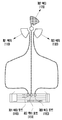
도 1a는 기지국에 배치되는 일반적인 안테나 모듈 구성 실시예를 나타낸 도면이다.1A is a diagram showing an exemplary configuration of a general antenna module disposed in a base station.
도 1a에 따르면, 제1 안테나 모듈은 제1 섹터(110)를 향하도록 기지국내에 배치될 수 있고, 제2 안테나 모듈은 제2 섹터(120)를 향하도록 기지국내에 배치될 수 있으며, 제3 안테나 모듈은 제3 섹터(130)를 향하도록 기지국내에 배치될 수 있다. 일실시예에 따르면, 상기 제1 섹터(110)는 기지국의 커버리지 내에서 특정 기준점을 기준으로 210°의 방위각을 중심으로 하는 영역일 수 있고, 상기 제2 섹터(120)는 기지국의 커버리지 내에서 특정 기준점을 기준으로 90°의 방위각을 중심으로 하는 영역일 수 있으며, 상기 제3 섹터(130)는 기지국의 커버리지 내에서 특정 기준점을 기준으로 330°의 방위각을 중심으로 하는 영역일 수 있다.According to FIG. 1A, the first antenna module may be disposed in the base station to face the first sector 110, and the second antenna module may be disposed in the base station to face the second sector 120. The three antenna modules may be arranged in the base station to face the third sector 130. According to an embodiment, the first sector 110 may be an area centered on an azimuth angle of 210 ° based on a specific reference point within the coverage of the base station, and the second sector 120 may be within the coverage of the base station. It may be an area centered on an azimuth angle of 90 ° based on a specific reference point, and the third sector 130 may be an area centered on an azimuth angle of 330 ° based on a specific reference point within the coverage of the base station.
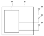
도 1a에 따르면, 상기 제1 섹터(110)를 향하는 제1 안테나 모듈은 전자 장치의 제1 섹터포트(140)와 전기적으로 연결될 수 있고, 상기 제2 섹터(120)를 향하는 제2 안테나 모듈은 전자 장치의 제2 섹터포트(150)와 전기적으로 연결될 수 있으며, 상기 제3 섹터(130)를 향하는 제3 안테나 모듈은 전자 장치의 제3 섹터포트(160)와 전기적으로 연결될 수 있다.According to FIG. 1A, the first antenna module facing the first sector 110 may be electrically connected to the
일실시예에 따르면, 상기 전자 장치는 기지국 내에 배치되거나 기지국 외부에 마련된 별도의 서버에 배치될 수 있다. 일실시예에 따르면, 상기 전자 장치는 상기 제1 섹터포트(140), 제2 섹터포트(150), 제3 섹터포트(160)를 통해 수신되는 전기적 신호를 통해 제1 섹터(110)를 향하는 제1 안테나 모듈, 제2 섹터(120)를 향하는 제2 안테나 모듈, 제3 섹터(130)를 향하는 제3 안테나 모듈의 방위각을 결정할 수 있다.According to one embodiment, the electronic device may be disposed in a base station or in a separate server provided outside the base station. According to an embodiment, the electronic device faces the first sector 110 through an electrical signal received through the
도 1b는 기지국에 배치되는 안테나 모듈 구성 실시예를 나타낸 도면이다.1B is a diagram showing an exemplary embodiment of an antenna module disposed in a base station.
도 1b에 따르면, 제1 안테나 모듈은 제1 섹터(110)를 향하도록 기지국내에 배치될 수 있고, 제2 안테나 모듈은 제2 섹터(120)를 향하도록 기지국내에 배치될 수 있으며, 제3 안테나 모듈은 제3 섹터(130)를 향하도록 기지국내에 배치될 수 있다. 일실시예에 따르면, 상기 제1 섹터(110)는 기지국의 커버리지 내에서 특정 기준점을 기준으로 210°의 방위각을 중심으로 하는 영역일 수 있고, 상기 제2 섹터(120)는 기지국의 커버리지 내에서 특정 기준점을 기준으로 40°의 방위각을 중심으로 하는 영역일 수 있으며, 상기 제3 섹터(130)는 기지국의 커버리지 내에서 특정 기준점을 기준으로 330°의 방위각을 중심으로 하는 영역일 수 있다.According to FIG. 1B, the first antenna module may be disposed in the base station to face the first sector 110, and the second antenna module may be disposed in the base station to face the second sector 120. The three antenna modules may be arranged in the base station to face the third sector 130. According to an embodiment, the first sector 110 may be an area centered on an azimuth angle of 210 ° based on a specific reference point within the coverage of the base station, and the second sector 120 may be within the coverage of the base station. It may be an area centered on an azimuth angle of 40 ° based on a specific reference point, and the third sector 130 may be an area centered on an azimuth angle of 330 ° based on a specific reference point within the coverage of the base station.
즉, 도 1b에 따른 구조에서 제2 섹터가 포함하는 영역은 도 1a에 따른 구조에서 제2 섹터가 포함하는 영역과 다를 수 있다. 예를 들어, 특정 기준점을 기준으로 80°-190°의 영역이 무선 통신이 필요 없는 영역이라면, 상기 80°-190°의 방위각 영역에는 안테나 모듈을 배치할 필요가 없으므로, 기지국은 도 1b에서 개시하고 있는 안테나 모듈 구조를 포함할 수 있다.That is, the region included in the second sector in the structure according to FIG. 1B may be different from the region included in the second sector in the structure according to FIG. 1A. For example, if an area of 80 ° -190 ° based on a specific reference point does not require wireless communication, the antenna module is not required to be disposed in the azimuth area of 80 ° -190 °, so the base station starts in FIG. 1B. It may include an antenna module structure.
도 1b에 따르면, 상기 제1 섹터(110)를 향하는 제1 안테나 모듈은 전자 장치의 제1 섹터포트(140)와 전기적으로 연결될 수 있고, 상기 제2 섹터(120)를 향하는 제2 안테나 모듈은 전자 장치의 제2 섹터포트(150)와 전기적으로 연결될 수 있으며, 상기 제3 섹터(130)를 향하는 제3 안테나 모듈은 전자 장치의 제3 섹터포트(160)와 전기적으로 연결될 수 있다.According to FIG. 1B, the first antenna module facing the first sector 110 may be electrically connected to the
일실시예에 따르면, 사업자(또는 오퍼레이터(operator))의 데이터베이스에 저장되어 있는 기지국 안테나 모듈의 방위각과 도 1b에서 도시한 안테나 모듈의 방위각은 일치하지 않을 수 있다. 예를 들어 앞서 언급한 이유로 제2 섹터가 특정 기준점을 기준으로 40°의 방위각을 중심으로 하는 영역임에도 불구하고, 데이터베이스에 저장되어 있는 제2 섹터는 특정 기준점을 기준으로 90°의 방위각을 중심으로 하는 영역일 수 있다. According to one embodiment, the azimuth of the base station antenna module stored in the database of the operator (or operator) may not match the azimuth of the antenna module illustrated in FIG. 1B. For example, although the second sector is an area centered on an azimuth angle of 40 ° based on a specific reference point for the aforementioned reason, the second sector stored in the database is centered on an azimuth angle of 90 ° based on a specific reference point. It may be an area.
일실시예에 따르면 실제 안테나 모듈의 방위각과 데이터베이스에 저장되어 있는 안테나 모듈간의 차이는 기지국 설치 후 초기 안테나 모듈의 방위각 측정 시 엔지니어의 오류 또는 측정된 안테나 모듈의 방위각을 데이터베이스에 저장하는 경우 발생 가능한 오류 등 다양한 원인에 기인할 수 있다.According to an embodiment, the difference between the azimuth of the actual antenna module and the antenna module stored in the database is an error that may occur when an engineer's error in measuring the azimuth of the initial antenna module after installing the base station or when storing the measured azimuth of the antenna module in the database It can be caused by various causes.
도 1c는 기지국에 배치되는 안테나 모듈 구성 실시예를 나타낸 도면이다.1C is a diagram showing an exemplary embodiment of an antenna module disposed in a base station.
도 1c에 따르면, 제1 안테나 모듈은 제1 섹터(110)를 향하도록 기지국내에 배치될 수 있고, 제2 안테나 모듈은 제2 섹터(120)를 향하도록 기지국내에 배치될 수 있으며, 제3 안테나 모듈은 제3 섹터(130)를 향하도록 기지국내에 배치될 수 있다. 일실시예에 따르면, 상기 제1 섹터(110)는 기지국의 커버리지 내에서 특정 기준점을 기준으로 210°의 방위각을 중심으로 하는 영역일 수 있고, 상기 제2 섹터(120)는 기지국의 커버리지 내에서 특정 기준점을 기준으로 90°의 방위각을 중심으로 하는 영역일 수 있으며, 상기 제3 섹터(130)는 기지국의 커버리지 내에서 특정 기준점을 기준으로 330°의 방위각을 중심으로 하는 영역일 수 있다.According to FIG. 1C, the first antenna module may be disposed in the base station facing the first sector 110, and the second antenna module may be disposed in the base station facing the second sector 120. The three antenna modules may be arranged in the base station to face the third sector 130. According to an embodiment, the first sector 110 may be an area centered on an azimuth angle of 210 ° based on a specific reference point within the coverage of the base station, and the second sector 120 may be within the coverage of the base station. It may be an area centered on an azimuth angle of 90 ° based on a specific reference point, and the third sector 130 may be an area centered on an azimuth angle of 330 ° based on a specific reference point within the coverage of the base station.
도 1c에 따르면, 상기 제1 섹터(110)를 향하는 제1 안테나 모듈은 전자 장치의 제3 섹터포트(160)와 전기적으로 연결될 수 있고, 상기 제2 섹터(120)를 향하는 제2 안테나 모듈은 전자 장치의 제2 섹터포트(150)와 전기적으로 연결될 수 있으며, 상기 제3 섹터(130)를 향하는 제3 안테나 모듈은 전자 장치의 제1 섹터포트(140)와 전기적으로 연결될 수 있다. 즉, 제1 섹터포트(140)와 제3 섹터포트(160)에 잘못된 섹터의 안테나 모듈이 전기적으로 연결될 수 있다.According to FIG. 1C, the first antenna module facing the first sector 110 can be electrically connected to the
도 1c와 같이 제1 섹터포트(140)와 제3 섹터포트(160)에 잘못된 섹터의 안테나 모듈이 전기적으로 연결되는 경우, 외관적으로는 기지국에 문제가 없는 것으로 보일 수 있으나, 실질적으로 제1 섹터(110)를 향하는 제1 안테나 모듈과 제3 섹터(130)를 향하는 제3 안테나 모듈이 서로 반대로 동작할 수 있다.When the antenna module of the wrong sector is electrically connected to the
도 2는 본 발명에 따른 기지국 방위각 결정 방법의 순서도이다.2 is a flowchart of a method for determining an azimuth of a base station according to the present invention.
일실시예에 따르면, S210 단계에서 기지국은 복수개의 단말로부터 각 단말의 위치 정보와 각 단말의 수신신호 세기 정보를 수신할 수 있다. 일실시예에 따르면 각 단말의 수신신호 세기 정보는 RSRP(reference signal received power) 또는 단말의 RF(radio frequency) 전계 정보일 수 있다.According to one embodiment, in step S210, the base station may receive location information of each terminal and received signal strength information of each terminal from a plurality of terminals. According to an embodiment, the received signal strength information of each terminal may be reference signal received power (RSRP) or radio frequency (RF) electric field information of the terminal.
일실시예에 따르면 S210 단계는 LBS(location based service) 서버 등 사업자의 위치정보 서버와의 연동을 이용한 방법 또는 MDT(minimize drive test) 기능을 이용한 방법 등을 통해 수행될 수 있다. 일실시예에 따르면 LBS 또는 MDT를 이용한 각 단말의 위치 정보 및 각 단말의 수신신호 세기 정보 수신 방법은 표준에 개시되어 있는 프로토콜 및 구성을 활용할 수 있다.According to an embodiment, step S210 may be performed through a method using an interworking with a location information server of an operator such as a location based service (LBS) server or a method using a minimize drive test (MDT) function. According to an embodiment, the method for receiving location information of each terminal using LBS or MDT and received signal strength information of each terminal may utilize the protocol and configuration disclosed in the standard.
일실시예에 따르면, 표준문서 3GPP TS 36.355에서 개시하고 있는 LPP(LTE positioning protocol) 기본구조에 따라 단말은 위성으로부터 GNSS(global navigation satellite system) 신호를 수신하는 동시에 단말의 위치 정보를 저장하는 서버와 상기 GNSS 신호에 기반한 단말의 위치 정보를 송수신할 수 있다. 즉, 표준문서 3GPP TS 36.355의 LPP 구조에 따르면, 기지국은 단말로부터 단말의 위치 정보를 수신할 수 있다.According to one embodiment, according to the basic structure of the LTE positioning protocol (LPP) disclosed in the standard document 3GPP TS 36.355, the terminal receives a global navigation satellite system (GNSS) signal from a satellite and simultaneously stores a location information of the terminal. It is possible to transmit and receive location information of a terminal based on the GNSS signal. That is, according to the LPP structure of the standard document 3GPP TS 36.355, the base station can receive the location information of the terminal from the terminal.
일실시예에 따르면, 표준문서 3GPP TS 37.320에서 개시하고 있는 MDT configuration 동작을 통해 기지국은 단말로부터 각 단말의 위치 정보와 각 단말의 수신신호 세기 정보를 수신할 수 있다. 일실시예에 따르면 기지국은 단말로 LoggedMeasurementConfiguration 메시지를 전송할 수 있으며, 단말은 상기 LoggedMeasurementConfiguration 메시지에 기반하여 위치 정보를 기지국으로 전송할 수 있다.According to an embodiment, the base station may receive location information of each terminal and received signal strength information of each terminal from the terminal through the MDT configuration operation disclosed in the standard document 3GPP TS 37.320. According to an embodiment, the base station may transmit a LoggedMeasurementConfiguration message to the terminal, and the terminal may transmit location information to the base station based on the LoggedMeasurementConfiguration message.
일실시예에 따르면, S210 단계는 단말에 설치된 어플리케이션을 이용해 수행 될 수 있다. 단말에 설치된 어플리케이션을 통해 각 단말의 위치 정보와 각 단말의 수신신호 세기 정보를 수신하는 방법은 도 3에 대한 설명을 통해 후술한다.According to one embodiment, step S210 may be performed using an application installed in the terminal. A method of receiving location information of each terminal and received signal strength information of each terminal through an application installed in the terminal will be described later with reference to FIG. 3.
일실시예에 따르면, S220 단계에서 기지국은 각 단말의 위치 정보와 각 단말의 수신신호 세기 정보에 기반하여 기지국의 커버리지(coverage)에 포함된 단말을 샘플링할 수 있다. S220 단계에 대한 구체적인 설명은 도 4에 대한 설명을 통해 후술한다.According to an embodiment, in step S220, the base station may sample the terminal included in the coverage of the base station based on the location information of each terminal and the received signal strength information of each terminal. The detailed description of step S220 will be described later with reference to FIG. 4.
일실시예에 따르면, S230 단계에서 기지국은 샘플링 결과에 기반하여 상기 기지국의 방위각을 결정할 수 있다. 일실시예에 따르면, 기지국이 복수개의 안테나 모듈을 포함하는 경우, 각 안테나 모듈의 방위각을 샘플링 결과에 기반하여 결정할 수 있다. S230 단계에 대한 구체적인 설명은 도 6에 대한 설명을 통해 후술한다.According to one embodiment, in step S230, the base station may determine the azimuth of the base station based on the sampling result. According to an embodiment, when the base station includes a plurality of antenna modules, an azimuth angle of each antenna module may be determined based on a sampling result. The detailed description of step S230 will be described later with reference to FIG. 6.
일실시예에 따르면, S240 단계에서 기지국은 S230 단계를 통해 결정된 기지국의 방위각과 데이터베이스에 저장되어 있는 기준 기지국 방위각을 비교하여 기지국의 정상 여부를 결정할 수 있다. 일실시예에 따르면, 기지국은 S230 단계를 통해 결정된 복수개 안테나 모듈의 방위각과 데이터베이스에 저장되어 있는 각 안테나 모듈의 기준 안테나 모듈 방위각을 비교하여 각 안테나 모듈의 정상 여부를 결정할 수 있다. S240 단계에 대한 구체적인 설명은 도 7에 대한 설명을 통해 후술한다.According to an embodiment, in step S240, the base station may determine whether the base station is normal by comparing the azimuth angle of the base station determined through step S230 with the reference base station azimuth angle stored in the database. According to an embodiment, the base station may determine whether each antenna module is normal by comparing the azimuth angles of the plurality of antenna modules determined through step S230 with the reference antenna module azimuth angles of each antenna module stored in the database. A detailed description of step S240 will be described later with reference to FIG. 7.
도 3은 단말에 설치된 어플리케이션을 통해 각 단말의 위치 정보를 획득하는 방법을 나타낸 도면이다.3 is a diagram showing a method of obtaining location information of each terminal through an application installed in the terminal.
일실시예에 따르면, 사업자 서버(310)는 단말(320)에 설치된 사업자 서버와 관련된 어플리케이션을 통해 단말의 위치 정보를 사업자 서버(310)에 보고할 것을 단말(320)에게 트리거링(S330) 할 수 있다. 예를 들어, 사업자 서버(310)가 네비게이션 관련 사업자라면, 사업자 서버(310)는 단말(320)에 설치된 네비게이션 어플을 통해 단말(320)에게 단말의 위치를 보고할 것을 트리거링(S330) 할 수 있다.According to an embodiment, the
일실시예에 따르면, 상기 트리거링(S330)은 주기적으로 수행될 수 있다. 예를 들어 단말(320)이 네비게이션 서비스를 이용하는 경우, 단말(320)은 실시간으로 단말의 위치 정보를 사업자 서버(310)에게 전송하기 위해 1ms 주기로 사업자 서버(310)에게 단말의 위치 정보를 전송할 수 있다.According to one embodiment, the triggering (S330) may be performed periodically. For example, when the terminal 320 uses a navigation service, the terminal 320 may transmit the location information of the terminal to the
일실시예에 따르면, 상기 트리거링(S330)은 이벤트에 기반하여 수행될 수 있다. 예를 들어, 단말(320)이 사업자 서버(310)가 제공하는 어플리케이션을 실행하는 경우 사업자 서버(310)는 단말(320)에게 단말의 수신 신호 세기가 -120dBm 이하인 경우, 위치정보를 전송할 것을 트리거링 할 수 있다.According to one embodiment, the triggering (S330) may be performed based on an event. For example, when the terminal 320 executes an application provided by the
일실시예에 따르면, 단말(320)은 S340 단계를 통해 사업자 서버(310)로 단말의 위치 정보 및 수신신호 세기 정보를 전송할 수 있다. 일실시예에 따르면, 단말은 S340 단계를 통해 단말의 위치 정보만을 전송할 수도 있다.According to an embodiment, the terminal 320 may transmit the location information and the received signal strength information of the terminal to the
도 3에서는 사업자 서버가 단말에게 트리거링 하는 경우만을 도시하고 있으나, 일실시예에 따르면, 기지국이 단말에게 단말의 위치 정보 및 단말의 수신신호 세기 정보를 전송하도록 트리거링 할 수 있다. 즉, 본 발명의 권리범위가 도 3에 개시되어 있는 실시예에 국한되어서는 안 될 것이다.3 illustrates only a case in which the operator server triggers the terminal, according to an embodiment, the base station may trigger the terminal to transmit the location information of the terminal and the received signal strength information of the terminal. That is, the scope of the present invention should not be limited to the embodiment disclosed in FIG. 3.
도 4는 본 발명의 일실시예에 따라 기지국이 커버리지에 포함된 단말을 샘플링하는 과정을 나타낸 순서도이다.4 is a flowchart illustrating a process in which a base station samples a terminal included in coverage according to an embodiment of the present invention.
일실시예에 따르면, S410 단계에서 기지국은 수신한 각 단말의 위치 정보에 기반하여 샘플의 유효성 유무를 판단할 수 있다. 예를 들어, 수신된 단말의 위치 정보에 기반한 단말의 위치가 기지국의 커버리지 내에 포함되는지 여부에 따라 상기 위치 정보를 전송한 단말이 샘플링을 수행하기 위한 샘플로써 적합한지 여부를 판단할 수 있다.According to an embodiment, in step S410, the base station may determine whether a sample is valid based on the received location information of each terminal. For example, it may be determined whether the terminal transmitting the location information is suitable as a sample for performing sampling according to whether the location of the terminal based on the received location information is included in the coverage of the base station.
일실시예에 따르면, 도 1a 내지 도 1c에서 개시한 바와 같이 기지국이 3 개의 안테나 모듈을 포함하는 경우, 제1 안테나 모듈이 수신한 단말의 위치 정보에 기반한 단말의 위치가 제1 안테나 모듈이 향하는 제1 섹터에 포함되는지 여부에 따라 상기 위치 정보를 전송한 단말이 샘플링을 수행하기 위한 샘플로써 적합한지 여부를 판단할 수 있다.According to an embodiment, when the base station includes three antenna modules, as illustrated in FIGS. 1A to 1C, the first antenna module faces the location of the terminal based on the location information of the terminal received by the first antenna module. Depending on whether or not it is included in the first sector, it may be determined whether the terminal transmitting the location information is suitable as a sample for performing sampling.
일실시예에 따르면, S410 단계에서 샘플이 유효하지 않다고 판단된 경우, S415 단계를 통해 기지국은 수신한 단말의 위치 정보를 무시할 수 있다. 예를 들어, 수신된 단말의 위치 정보에 기반한 단말의 위치가 기지국의 커버리지에 포함되지 않는 경우, 기지국은 상기 위치 정보를 전송한 단말이 샘플링을 수행하기 위한 샘플로써 부적합하도 판단하며, 상기 위치 정보를 버릴 수 있다.According to an embodiment, if it is determined in step S410 that the sample is not valid, the base station may ignore the received location information of the terminal through step S415. For example, if the location of the terminal based on the received location information of the terminal is not included in the coverage of the base station, the base station determines whether the terminal that has transmitted the location information is unsuitable as a sample for performing sampling, and the location information Can throw away.
일실시예에 따르면, S410 단계에서 샘플이 유효하다고 판단된 경우, S420 단계에서 기지국은 위치 정보를 수신한 단말의 개수가 기설정된 제1 기준값 이상인지 여부를 판단할 수 있다. 일실시예에 따르면, 상기 제1 기준값은 샘플링의 정확성 척도가 될 수 있다. 제1 기준값이 클수록 기지국이 수집하는 단말의 위치 정보 개수가 많아지므로 기지국에 의한 샘플링 정확도가 향상될 수 있다. 반면 제1 기준값이 작아질수록 기지국의 샘플링을 수행하는 속도가 빨라질 수 있다.According to an embodiment, if it is determined in step S410 that the sample is valid, in step S420, the base station may determine whether the number of terminals receiving the location information is greater than or equal to a preset first reference value. According to an embodiment, the first reference value may be a measure of accuracy of sampling. The larger the first reference value, the greater the number of location information of the terminal collected by the base station, so that the sampling accuracy by the base station can be improved. On the other hand, the smaller the first reference value, the faster the base station performs sampling.
일실시예에 따르면, S425 단계에서 기지국은 각 단말의 위치 정보에 기반하여 기지국의 커버리지를 기설정된 면적을 가지는 단위 셀로 분할할 수 있다. 예를 들어, 기지국은 기지국의 커버리지를 5m*5m의 정사각형 형상을 가지는 단위 셀로 분할할 수 있다.According to an embodiment, in step S425, the base station may divide the coverage of the base station into unit cells having a predetermined area based on the location information of each terminal. For example, the base station may divide the coverage of the base station into unit cells having a square shape of 5m * 5m.
일실시예에 따르면, 상기 S425 단계는 생략될 수 있다. 즉, 기지국은 기지국의 커버리지를 단위 셀로 분할하지 않고, 단말로부터 수신한 단말의 위치 정보에 기반하여 결정된 각 단말의 위치별로 수신신호 세기를 결정하여 샘플링을 수행할 수 있다.According to an embodiment, step S425 may be omitted. That is, the base station does not divide the coverage of the base station into unit cells, and can perform sampling by determining the received signal strength for each location of each terminal determined based on the location information of the terminal received from the terminal.
일실시예에 따르면, S430 단계에서 단말은 각 단위 셀에 포함된 단말의 수신신호 세기 정보에 기반하여 각 단위 셀의 수신신호 세기를 결정할 수 있다. 일실시예에 따르면 각 단위 셀의 수신신호 세기는 각 단위 셀에 포함된 단말로부터 수신되는 신호세기의 평균일 수 있다. 예를 들어, 제1 단위 셀에 단말이 2개 포함되어 있고, 제2 단위 셀에는 단말이 3개 포함되어 있으며, 제1 단위 셀에 포함된 단말로부터 수신된 각 단말의 수신신호 세기가 -5dB 와 -3dB이며, 제2 단위 셀이 포함된 단말로부터 수신된 각 단말의 수신신호 세기가 -10dB, -3dB, -5dB 인 경우, 제1 단위 셀의 수신신호 세기는 -4dB일 수 있으며, 제2 단위 셀의 수신신호 세기는 -6dB일 수 있다.According to an embodiment, in step S430, the terminal may determine the received signal strength of each unit cell based on the received signal strength information of the terminal included in each unit cell. According to an embodiment, the received signal strength of each unit cell may be an average of the signal strength received from a terminal included in each unit cell. For example, two terminals are included in the first unit cell, three terminals are included in the second unit cell, and the received signal strength of each terminal received from the terminal included in the first unit cell is -5dB. And -3dB, and when the received signal strength of each terminal received from the terminal including the second unit cell is -10dB, -3dB, -5dB, the received signal strength of the first unit cell may be -4dB, The received signal strength of the 2 unit cells may be -6dB.
일실시예에 따르면, S435 단계에서 기지국은 각 단위 셀의 수신신호 세기가 기설정된 문턱값 이상인 단위 셀을 확인할 수 있다. 예를 들어 제1 단위 셀의 수신신호 세기가 -10dB이고, 제2 단위 셀의 수신신호 세기가 -12dB이며, 제3 단위 셀의 수신신호 세기가 -30dB이고, 기설정된 문턱값이 -25dB인 경우, 기지국은 제1 단위 셀과 제2 단위 셀이 기설정된 문턱값 이상인 단위 셀임을 확인할 수 있다.According to an embodiment, in step S435, the base station may identify a unit cell in which the received signal strength of each unit cell is equal to or greater than a preset threshold. For example, the received signal strength of the first unit cell is -10dB, the received signal strength of the second unit cell is -12dB, the received signal strength of the third unit cell is -30dB, and the preset threshold is -25dB. In this case, the base station can confirm that the first unit cell and the second unit cell are unit cells having a predetermined threshold or higher.
일실시예에 따르면, S440 단계에서 기지국은 수신신호 세기가 기설정된 문턱값 이상인 단위 셀에 대해 가중치를 적용할 수 있다. 앞선 예를 인용하면, 기지국은 기설정된 문턱값 이상의 수신신호 세기를 가지는 제1 단위 셀과 제2 단위 셀에 가중치를 적용할 수 있다. 일실시예에 따르면, 상기 가중치는 샘플링 단계에서 각 단위 셀별로 신뢰도를 적용하는 단계로 볼 수 있다. 예를 들어 기지국의 boresignt 방향은 기지국의 전계가 강하게 형성되므로, 기지국은 전계가 강하게 형성된 단위 셀(즉, 수신신호 세기가 기설정된 문턱값 이상인 단위 셀)에 대해서는 가중치를 적용할 수 있다. 한편, 상기 S450 단계와 S460 단계는 생략될 수 있다. 즉, 기지국은 각 단위 셀에 대해 가중치를 적용하지 않고 샘플링 동작을 수행할 수도 있다.According to an embodiment, in step S440, the base station may apply a weight to a unit cell in which the received signal strength is greater than or equal to a preset threshold. Referring to the previous example, the base station may apply weights to the first unit cell and the second unit cell having received signal strengths greater than or equal to a preset threshold. According to an embodiment, the weight may be regarded as a step of applying reliability for each unit cell in the sampling step. For example, in the boresignt direction of the base station, since the electric field of the base station is strongly formed, the base station may apply a weight to a unit cell in which the electric field is strongly formed (ie, a unit cell in which the received signal strength is greater than or equal to a preset threshold). Meanwhile, steps S450 and S460 may be omitted. That is, the base station may perform a sampling operation without applying weights to each unit cell.
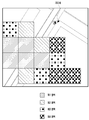
도 5는 본 발명의 일실시예에 따라 샘플링된 기지국의 커버리지를 나타낸 도면이다.5 is a diagram illustrating coverage of a sampled base station according to an embodiment of the present invention.
일실시예에 따르면, 기지국의 커버리지는 도 5에서 도시하고 있는 바와 같이 14개의 단위 셀을 포함할 수 있으며, 14개의 단위 셀은 각 단위 셀의 수신신호 세기에 따라 4개의 영역으로 구분될 수 있다. 일실시예에 따르면, 수신신호 세기가 -70dB 이상인 단위 셀이 제1 영역에 포함될 수 있으며, 수신신호 세기가 -75dB 이상이며 -70dB 미만인 단위 셀이 제2 영역에 포함될 수 있고, 수신신호 세기가 -80dB 이상이며 -75dB 미만인 단위 셀이 제3 영역에 포함될 수 있으며, 수신신호 세기가 -55dB 이상이며 -75dB 미만인 단위 셀이 제4 영역에 포함될 수 있다.According to an embodiment, the coverage of the base station may include 14 unit cells, as shown in FIG. 5, and the 14 unit cells may be divided into 4 regions according to the received signal strength of each unit cell. . According to an embodiment, a unit cell having a received signal strength of -70 dB or more may be included in the first region, a unit cell having a received signal strength of -75 dB or more and less than -70 dB may be included in the second region, and the received signal strength A unit cell having -80 dB or more and less than -75 dB may be included in the third region, and a unit cell having a received signal strength of -55 dB or more and less than -75 dB may be included in the fourth region.
일실시예에 따르면, 수신신호 세기가 비교적 큰 상기 제1 영역에 포함된 단위 셀과 상기 제2 영역에 포함된 단위 셀이 기지국의 전계가 강하게 형성된 영역이라고 볼 수 있으며, 기지국은 상기 제1 영역에 포함된 단위 셀과 상기 제2 영역에 포함된 단위 셀에 가중치를 적용하여 기지국 방위각 결정의 정확도를 향상시킬 수 있다.According to an embodiment, the unit cell included in the first region and the unit cell included in the second region having a relatively large received signal strength may be regarded as regions in which the electric field of the base station is strongly formed. The accuracy of the base station azimuth determination may be improved by applying weights to the unit cells included in and the unit cells included in the second region.
도 6a 및 도 6b는 기지국의 방위각을 결정하는 방법을 나타낸 도면이다.6A and 6B are diagrams illustrating a method of determining an azimuth angle of a base station.
도 6a에서 개시하고 있는 일실시예에 따르면, 기지국(610)의 커버리지 내에 9개의 단위 셀(621, 622, 623, 624, 625, 626, 627, 628, 629)이 포함될 수 있다. 일실시예에 따르면, 기지국은 상기 각 단위 셀(621, 622, 623, 624, 625, 626, 627, 628, 629)의 방위각에 기반하여 상기 기지국(610)의 방위각을 결정할 수 있다. 예를 들어 각 단위 셀 방위각의 평균이 67°인 경우, 기지국은 상기 기지국(610)의 방위각을 67°로 결정할 수 있다.According to an embodiment disclosed in FIG. 6A, nine
일실시예에 따르면, 기지국은 각 단위 셀에 가중치를 적용하여 기지국의 방위각을 결정할 수 있다. 예를 들어 624 단위 셀과, 626 단위 셀에 가중치가 부여되는 경우, 624 단위 셀의 방위각과 626 단위 셀의 방위각에 가중치를 적용한 후, 각 단위 셀(621, 622, 623, 624, 625, 626, 627, 628, 629) 방위각의 평균값을 계산하여, 기지국의 방위각을 결정할 수 있다.According to an embodiment, the base station may determine the azimuth of the base station by applying a weight to each unit cell. For example, if weight is applied to the 624 unit cell and the 626 unit cell, after applying weights to the azimuth angle of the 624 unit cell and the azimuth angle of the 626 unit cell, each
일실시예에 따르면, 기지국(610)은 각 단위 셀의 위치 정보에 기반하여 기지국의 방위각을 결정할 수 있다. 일실시예에 따르면 기지국은 각 단위 셀에 포함된 단말의 위치 정보에 기반하여 각 단위 셀의 위치 정보를 결정할 수 있으며, 결정된 각 단위 셀의 위치 정보의 평균값을 계산하여 기지국의 방위각을 결정할 수 있다. 일실시예에 따르면, 기지국은 각 단위 셀의 위치 정보에 가중치를 적용하여 기지국의 방위각을 결정할 수 있다.According to one embodiment, the
도 6b에서 개시하고 있는 일실시예에 따르면, 기지국은 기설정된 기지국의 전파 방사 패턴(640)과 각 단위 셀(621, 622, 623, 624, 625, 626, 627, 628, 629)의 수신신호 세기간의 상관관계(correlation)에 기반하여 기지국의 방위각을 결정할 수 있다.According to one embodiment disclosed in Figure 6b, the base station is a radio
일실시예에 따르면, 기지국은 기설정된 전파 방사 패턴(640)을 0°에서 360°지 회전시키며, 전파 방사 패턴(640)과 각 단위 셀(621, 622, 623, 624, 625, 626, 627, 628, 629)의 수신신호 세기간의 상관관계를 측정할 수 있다. 일실시예에 따르면, 기지국은 각 단위 셀의 수신신호 세기와 상관관계가 가장 높은 전파 방사 패턴(640)의 방위각을 기지국(610)의 방위각으로 결정할 수 있다.According to an embodiment, the base station rotates the preset
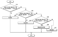
도 7은 본 발명의 일실시예에 따라 기지국의 정상 여부를 결정하는 방법을 나타낸 순서도이다.7 is a flowchart illustrating a method of determining whether a base station is normal according to an embodiment of the present invention.
일실시예에 따르면, 기지국은 도 1a 내지 도 1c에서 개시하고 있는 바와 같이세 개의 안테나 모듈을 포함할 수 있으며, 각 안테나 모듈은 기지국의 커버리지 내에서 서로 다른 섹터를 향해 배치될 수 있다. 예를 들어 제1 안테나 모듈은 제1 섹터를 향해 배치되고, 제2 안테나 모듈은 제2 섹터를 향해 배치되며, 제3 안테나 모듈은 제3 섹터를 향해 배치될 수 있다.According to an embodiment, the base station may include three antenna modules as disclosed in FIGS. 1A to 1C, and each antenna module may be disposed toward different sectors within the coverage of the base station. For example, the first antenna module may be arranged toward the first sector, the second antenna module may be arranged toward the second sector, and the third antenna module may be arranged toward the third sector.
일실시예에 따르면, 기지국은 각 안테나 모듈을 통해 수신되는 단말의 위치 정보와 단말의 수신신호 세기 정보에 기반하여 각 섹터를 단위 셀로 분할하여 샘플링을 수행할 수 있으며, 샘플링된 결과에 기반하여 각 안테나 모듈의 방위각을 결정할 수 있다.According to one embodiment, the base station based on received signal strength information of the location information and the terminal of the terminal is received through each antenna module dividing each sector cell unit may perform sampling, based on the sampling result The azimuth angle of each antenna module can be determined.
일실시예에 따르면, S710 단계에서 기지국은 결정된 제1 안테나 모듈의 방위각과 기준 제1 안테나 모듈 방위각의 차이가 기설정된 제1 문턱값 이하인지 여부를 판단할 수 있다. 일실시예에 따르면, 상기 기준 제1 안테나 모듈 방위각은 기지국의 데이터베이스에 저장되어 있는 값일 수 있으며, 최초 기지국 설치 시 제1 안테나 모듈의 방위각일 수 있다. 일실시예에 따르면 상기 기준 제1 안테나 모듈 방위각은 상기 기지국이 배치되는 지역(예를 들어 강, 산, 바다, 고속도로 등)에 따라 다르게 결정될 수 있다. According to one embodiment, in step S710, the base station may determine whether the difference between the determined azimuth angle of the first antenna module and the reference first antenna module azimuth is equal to or less than a preset first threshold. According to an embodiment, the reference first antenna module azimuth may be a value stored in the database of the base station, or may be the azimuth of the first antenna module when the first base station is installed. According to an embodiment, the reference first antenna module azimuth may be differently determined according to an area (eg, river, mountain, sea, highway, etc.) in which the base station is disposed.
일실시예에 따르면, 결정된 제1 안테나 모듈의 방위각과 기준 제1 안테나 모듈 방위각의 차이가 기설정된 제1 문턱값 이하인 경우, S720 단계에서 기지국은 제1 안테나 모듈이 정상상태에 있다고 판단할 수 있다. 즉, 기지국은 현재 제1 안테나 모듈의 방위각과 최초 기지국 설치 시 제1 안테나 모듈의 방위각간의 오차가 크지 않다면, 기지국은 제1 안테나 모듈이 정상상태에 있다고 판단할 수 있다. 한편, 기지국은 현재 제1 안테나 모듈의 방위각과 최초 기지국 설치 시 제1 안테나 모듈의 방위각간의 오차가 크다면, 즉, 제1 문턱값보다 큰 경우, 기지국은 제1 안테나 모듈이 비정상상태에 있다고 판단할 수 있다. 일실시예에 따르면, 기지국은 제1 안테나 모듈의 방위각에 이상이 있다고 판단된 경우, 상기 기지국의 사업자에게 제1 안테나 모듈 방위각에 이상이 있음을 알릴 수 있다. 일실시예에 따르면, 사업자는 기지국으로부터 상기 기지국에 포함되어 있는 각 안테나 모듈 방위각의 이상유무를 보고받을 수 있으므로 기지국 안테나 모듈 방위각에 이상이 발생하는 경우 즉각적으로 대응할 수 있다.According to an embodiment, when the difference between the determined azimuth of the first antenna module and the reference first antenna module azimuth is equal to or less than a preset first threshold, in step S720, the base station may determine that the first antenna module is in a normal state. . That is, if the error between the azimuth of the first antenna module and the azimuth of the first antenna module is not large when the first base station is installed, the base station may determine that the first antenna module is in a normal state. On the other hand, if the error between the azimuth of the first antenna module and the azimuth of the first antenna module is large when installing the first base station, that is, if it is greater than the first threshold, the base station determines that the first antenna module is in an abnormal state. can do. According to an embodiment, when it is determined that the azimuth of the first antenna module is abnormal, the base station may inform the operator of the base station that the azimuth of the first antenna module is abnormal. According to one embodiment, the operator can report the presence or absence of an abnormality in each antenna module azimuth included in the base station from the base station, so that an abnormality occurs in the azimuth of the base station antenna module.
일실시예에 따르면 상기 제1 문턱값은 제1 안테나 모듈과 단말간의 채널상태에 기반하여 결정될 수 있다. 예를 들어 제1 안테나 모듈과 단말간의 채널상태가 일정하지 못한 경우의 제1 문턱값이 제1 안테나 모듈과 단말간의 채널상태가 일정한 경우의 제1 문턱값보다 크게 결정될 수 있다. 또한 상기 제1 문턱값은 안테나 모듈 사이의 방위각 차에 의해 결정될 수 있다. 예를 들어 제1 안테나 모듈과 제2 안테나 모듈간의 방위각 차이가 큰 경우의 제1 문턱값이 제1 안테나 모듈과 제2 안테나 모듈간의 방위각 차이가 작은 경우의 제1 문턱값 보다 크게 결정될 수 있다.According to an embodiment, the first threshold value may be determined based on a channel state between the first antenna module and the terminal. For example, the first threshold value when the channel state between the first antenna module and the terminal is not constant may be determined to be greater than the first threshold value when the channel state between the first antenna module and the terminal is constant. Also, the first threshold value may be determined by an azimuth difference between antenna modules. For example, the first threshold value when the azimuth difference between the first antenna module and the second antenna module is large may be determined to be greater than the first threshold value when the azimuth difference between the first antenna module and the second antenna module is small.
일실시예에 따르면, S730 단계에서 기지국은 비정상 상태로 확인된 결정된 제1 안테나 모듈의 방위각과 기준 제3 안테나 모듈 방위각의 차이가 기설정된 제2 문턱값 이상인지 여부를 판단할 수 있다. 일실시예에 따르면, 결정된 제1 안테나 모듈의 방위각과 기준 제3 안테나 모듈 방위각의 차이가 기설정된 제2 문턱값 이하인 경우, S730 단계에서 기지국은 제1 안테나 모듈이 제3 안테나 모듈에 대한 포트에 전기적으로 연결되었다고 의심할 수 있다.According to an embodiment, in step S730, the base station may determine whether a difference between the determined azimuth angle of the determined first antenna module and the reference third antenna module azimuth is greater than or equal to a second preset threshold. According to an embodiment, when the difference between the determined azimuth of the first antenna module and the reference third antenna module azimuth is equal to or less than a preset second threshold, in step S730, the base station determines whether the first antenna module is connected to a port for the third antenna module. It can be suspected that they are electrically connected.
일실시예에 따르면 상기 제2 문턱값은 제1 안테나 모듈과 단말간의 채널상태에 기반하여 결정될 수 있다. 예를 들어 제1 안테나 모듈과 단말간의 채널상태가 일정하지 못한 경우의 제2 문턱값이 제1 안테나 모듈과 단말간의 채널상태가 일정한 경우의 제2 문턱값보다 크게 결정될 수 있다. 또한 상기 제2 문턱값은 안테나 모듈 사이의 방위각 차에 의해 결정될 수 있다. 예를 들어 제1 안테나 모듈과 제3 안테나 모듈간의 방위각 차이가 큰 경우의 제2 문턱값이 제1 안테나 모듈과 제3 안테나 모듈간의 방위각 차이가 작은 경우의 제2 문턱값 보다 크게 결정될 수 있다.According to an embodiment, the second threshold value may be determined based on a channel state between the first antenna module and the terminal. For example, the second threshold value when the channel state between the first antenna module and the terminal is not constant may be determined to be greater than the second threshold value when the channel state between the first antenna module and the terminal is constant. Also, the second threshold may be determined by an azimuth difference between antenna modules. For example, the second threshold value when the azimuth difference between the first antenna module and the third antenna module is large may be determined to be greater than the second threshold value when the azimuth difference between the first antenna module and the third antenna module is small.
일실시예에 따르면, 결정된 제1 안테나 모듈의 방위각과 기준 제3 안테나 모듈 방위각의 차이가 기설정된 제2 문턱값 이하인 경우, 기지국은 제1 안테나 모듈이 제3 안테나 모듈과 관련된 포트에 전기적으로 연결되었을 가능성이 높다고 판단할 수 있다.According to an embodiment, when the difference between the determined azimuth of the first antenna module and the reference third antenna module azimuth is equal to or less than a preset second threshold, the base station electrically connects the first antenna module to a port associated with the third antenna module It can be judged that it is likely to have been.
일실시예에 따르면, S750 단계에서 기지국은 결정된 제3 안테나 모듈의 방위각과 기준 제1 안테나 모듈 방위각의 차이가 기설정된 제3 문턱값 이하인지 여부를 판단할 수 있다. 일실시예에 따르면, 상기 기준 제1 안테나 모듈 방위각은 기지국의 데이터베이스에 저장되어 있는 값일 수 있으며, 최초 기지국 설치 시 제1 안테나 모듈의 방위각일 수 있다.According to an embodiment, in step S750, the base station may determine whether the difference between the determined azimuth angle of the third antenna module and the reference first antenna module azimuth is equal to or less than a preset third threshold. According to an embodiment, the reference first antenna module azimuth may be a value stored in the database of the base station, or may be the azimuth of the first antenna module when the first base station is installed.
일실시예에 따르면, 제3 안테나 모듈의 방위각과 기준 제1 안테나 모듈 방위각의 차이가 기설정된 제3 문턱값 이하인 경우, 현재 제3 안테나 모듈의 방위각과 최초 기지국 설치 시 제1 안테나 모듈의 방위각이 유사하다고 판단될 수 있다. According to an embodiment, when the difference between the azimuth angle of the third antenna module and the reference first antenna module azimuth is equal to or less than a preset third threshold, the azimuth angle of the current third antenna module and the azimuth angle of the first antenna module when the first base station is installed It can be considered similar.
일실시예에 따르면, 제3 안테나 모듈의 방위각과 기준 제1 안테나 모듈 방위각의 차이가 기설정된 제3 문턱값 이하인 경우, 상기 제1 안테나 모듈과 전기적으로 연결되어야 할 제1 안테나 모듈에 대한 포트에 제3 안테나 모듈이 전기적으로 연결되었고, 제3 안테나 모듈과 전기적으로 연결되어야 할 제3 안테나 모듈에 대한 포트에 제1 안테나 모듈이 전기적으로 연결되었다고 판단할 수 있다. 즉 S760 단계에서 제3 안테나 모듈의 방위각과 기준 제1 안테나 모듈 방위각의 차이가 기설정된 제3 문턱값 이하인 경우, 기지국은 케이블 연결에 오류가 발생하였음을 판단할 수 있다.According to an embodiment, when the difference between the azimuth angle of the third antenna module and the reference first antenna module azimuth is equal to or less than a preset third threshold, a port for the first antenna module to be electrically connected to the first antenna module is provided. It may be determined that the third antenna module is electrically connected, and the first antenna module is electrically connected to a port for the third antenna module to be electrically connected to the third antenna module. That is, when the difference between the azimuth angle of the third antenna module and the reference first antenna module azimuth angle is less than a preset third threshold in step S760, the base station may determine that an error has occurred in the cable connection.
일실시예에 따르면, S770 단계에서 제3 안테나 모듈의 방위각과 기준 제1 안테나 모듈 방위각의 차이가 기설정된 제3 문턱값을 초과하는 경우, 기지국은 제1 안테나 모듈이 비정상 상태에 있다고 판단할 수 있다. 즉, 기지국은 현재 제1 안테나 모듈의 방위각에 이상이 있음을 확인할 수 있다.According to an embodiment, when the difference between the azimuth angle of the third antenna module and the reference first antenna module azimuth angle in step S770 exceeds a preset third threshold, the base station may determine that the first antenna module is in an abnormal state. have. That is, the base station can confirm that there is an abnormality in the azimuth of the first antenna module.
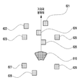
도 8은 본 발명의 일실시예에 따른 기지국의 구성을 나타낸 도면이다.8 is a view showing the configuration of a base station according to an embodiment of the present invention.
일실시예에 따르면, 본 발명에 따른 기지국(800)은 상기 기지국의 커버리지 중 제1 섹터를 향하는 제1 안테나 모듈(820), 상기 기지국의 커버리지 중 제2 섹터를 향하는 제2 안테나 모듈(830), 상기 기지국의 커버리지 중 제3 섹터를 향하는 제3 안테나 모듈(840)을 포함할 수 있다.According to one embodiment, the
일실시예에 따르면, 상기 제1 섹터, 제2 섹터, 제3 섹터는 상기 기지국의 커버리지 내에서 서로 중첩되지 않을 수 있다. 즉, 상기 제1 안테나 모듈, 상기 제2 안테나 모듈, 상기 제3 안테나 모듈의 방위각은 서로 다를 수 있다.According to an embodiment, the first sector, the second sector, and the third sector may not overlap each other within the coverage of the base station. That is, the azimuth angles of the first antenna module, the second antenna module, and the third antenna module may be different.
일실시예에 따르면, 제어부(810)는 제1 안테나 모듈(820), 제2 안테나 모듈(830), 제3 안테나 모듈(840)을 제어하여 복수개의 단말로부터 각 단말의 위치 정보와 각 단말의 수신신호 세기 정보를 수신할 수 있다. 일실시예에 따르면, 제어부(810)는 각 단말의 위치 정보와 각 단말의 수신신호 세기 정보에 기반하여 제1 안테나 모듈(820)이 향하는 제1 섹터에 포함된 단말, 제2 안테나 모듈(830)이 향하는 제2 섹터에 포함된 단말, 제3 안테나 모듈(840)이 향하는 제3 섹터에 포함된 단말을 샘플링할 수 있다. 일실시예에 따르면, 제어부(810)는 제1 섹터의 샘플링된 정보에 기반하여 상기 제1 안테나 모듈(820)의 방위각을 결정하고, 제2 섹터의 샘플링된 정보에 기반하여 상기 제2 안테나 모듈(830)의 방위각을 결정하며, 제3 섹터의 샘플링된 정보에 기반하여 상기 제3 안테나 모듈(840)의 방위각을 결정할 수 있다.According to one embodiment, the
일실시예에 따르면, 본 발명에 따른 무선 통신 시스템에서 기지국의 방위각 결정 방법은 복수개의 단말로부터 각 단말의 위치 정보와 각 단말의 수신신호 세기 정보를 수신하는 단계, 상기 각 단말의 위치 정보와 상기 각 단말의 수신신호 세기 정보에 기반하여 상기 기지국의 커버리지(coverage)에 포함된 단말을 샘플링(sampling)하는 단계 및 상기 샘플링 결과에 기반하여 상기 기지국의 방위각을 결정하는 단계를 포함할 수 있다.According to an embodiment, in a wireless communication system according to the present invention, a method for determining an azimuth angle of a base station includes receiving location information of each terminal and received signal strength information of each terminal from a plurality of terminals, and the location information of each terminal and the The method may include sampling a terminal included in coverage of the base station based on received signal strength information of each terminal, and determining an azimuth angle of the base station based on the sampling result.
일실시예에 따르면, 본 발명에 따른 기지국의 방위각 결정 방법은 각 단말에 설치된 어플리케이션을 통해 각 단말에게 각 단말의 위치 정보와 각 단말의 수신신호 세기 정보를 전송하도록 트리거하는 단계를 더 포함하며, 상기 트리거 단계는 기설정된 주기간격으로 수행될 수 있다.According to one embodiment, the method for determining the azimuth of a base station according to the present invention further includes triggering to transmit location information of each terminal and received signal strength information of each terminal to each terminal through an application installed in each terminal, The trigger step may be performed at a predetermined main period.
일실시예에 따르면, 상기 샘플링 단계는 상기 각 단말의 위치 정보에 기반하여 기지국의 커버리지를 기설정된 면적을 가지는 단위 셀로 분할하는 단계 및 상기 각 단위 셀에 포함된 단말의 수신신호 세기 정보에 기반하여 각 단위 셀의 수신신호 세기를 결정하는 단계를 포함할 수 있다.According to one embodiment, the sampling step is based on the location information of each terminal to divide the coverage of the base station into a unit cell having a predetermined area and based on the received signal strength information of the terminal included in each unit cell And determining the strength of the received signal of each unit cell.
일실시예에 따르면, 본 발명에 따른 기지국의 방위각 결정 방법은 상기 각 단위 셀의 수신신호 세기가 기설정된 문턱값 이상인 단위 셀을 확인하는 단계 및 수신신호 세기가 기설정된 문턱값 이상인 단위 셀에 대해 가중치를 적용하는 단계를 더 포함할 수 있다.According to an embodiment, the method for determining the azimuth angle of a base station according to the present invention includes: checking a unit cell in which the received signal strength of each unit cell is greater than or equal to a preset threshold; and a unit cell in which the received signal strength is greater than or equal to a preset threshold value. The method may further include applying weights.
일실시예에 따르면, 상기 기지국 방위각 결정 단계는 상기 각 단위 셀의 방위각의 평균값에 기반하여 상기 기지국의 방위각을 결정할 수 있다.According to an embodiment, the determining the azimuth of the base station may determine the azimuth of the base station based on the average value of the azimuth of each unit cell.
일실시예에 따르면, 상기 기지국 방위각 결정 단계는 기설정된 상기 기지국의 전파 방사 패턴을 확인하는 단계 및 상기 전파 방사 패턴과 상기 각 단위 셀의 수신신호 세기간의 상관관계(correlation)에 기반하여 상기 기지국의 방위각을 결정하는 단계를 포함할 수 있다.According to one embodiment, the base station azimuth determination step is based on a correlation between the radio wave radiation pattern and the received signal strength of each unit cell and the step of confirming the predetermined radio wave pattern of the base station. And determining the azimuth angle.
일실시예에 따르면, 상기 기지국 방위각 결정 단계는 결정된 상기 기지국의 방위각과 기설정된 기준 기지국 방위각에 기반하여 상기 기지국의 정상 여부를 결정하는 단계를 더 포함할 수 있다.According to an embodiment, the determining of the base station azimuth may further include determining whether the base station is normal based on the determined azimuth of the base station and a predetermined reference base station azimuth.
일실시예에 따르면, 상기 기지국의 정상 여부 결정 단계는 결정된 상기 기지국의 방위각과 상기 기준 기지국 방위각 차이가 기설정된 제1 문턱값 이하인 경우, 상기 기지국을 정상으로 판단할 수 있다.According to an embodiment, the determining whether the base station is normal may determine that the base station is normal if the determined difference between the azimuth of the base station and the reference base station azimuth is equal to or less than a preset first threshold.
일실시예에 따르면, 상기 기지국의 정상 여부 결정 단계는 결정된 상기 기지국의 방위각과 상기 기준 기지국 방위각 차이가 기설정된 제2 문턱값 이상인 경우, 상기 기지국을 비정상으로 판단할 수 있다.According to an embodiment, when determining whether the base station is normal, if the determined difference between the azimuth of the base station and the reference base station azimuth is greater than or equal to a second preset threshold, the base station may be determined as abnormal.
일실시예에 따르면, 상기 제1 문턱값과 상기 제2 문턱값은 상기 기지국의 커버리지에 포함된 단말과 상기 기지국간의 채널 상태 또는 주변 기지국간의 방위각 차이에 기반하여 결정될 수 있다.According to an embodiment, the first threshold value and the second threshold value may be determined based on a channel state between a terminal included in the coverage of the base station and the base station or an azimuth difference between neighboring base stations.
일실시예에 따르면 본 발명은 단말로 신호를 송수신하는 적어도 하나의 안테나 모듈 및 복수개의 단말로부터 각 단말의 위치 정보와 각 단말의 수신신호 세기 정보를 수신하도록 상기 적어도 하나의 안테나 모듈을 제어하고, 상기 각 단말의 위치 정보와 상기 각 단말의 수신신호 세기 정보에 기반하여 상기 기지국의 커버리지(coverage)에 포함된 단말을 샘플링(sampling)하며, 상기 샘플링 결과에 기반하여 상기 적어도 하나의 안테나 모듈의 방위각을 결정하는 제어부를 포함하는 기지국을 제공한다.According to an embodiment of the present invention, at least one antenna module for transmitting and receiving signals to and from a plurality of terminals and controlling the at least one antenna module to receive location information of each terminal and received signal strength information of each terminal from a plurality of terminals, Sampling a terminal included in coverage of the base station based on the location information of each terminal and the received signal strength information of each terminal, and azimuth angle of the at least one antenna module based on the sampling result It provides a base station including a control unit for determining.
일실시예에 따르면, 상기 제어부는 상기 각 단말의 위치 정보에 기반하여 기지국의 커버리지를 기설정된 면적을 가지는 단위 셀로 분할하고, 상기 각 단위 셀에 포함된 단말의 수신신호 세기 정보에 기반하여 각 단위 셀의 수신신호 세기를 결정할 수 있다.According to one embodiment, the control unit divides the coverage of the base station into unit cells having a predetermined area based on the location information of each terminal, and each unit based on the received signal strength information of the terminal included in each unit cell The received signal strength of the cell can be determined.
일실시예에 따르면, 상기 제어부는 상기 각 단위 셀의 수신신호 세기가 기설정된 문턱값 이상인 단위 셀을 확인하고, 수신신호 세기가 기설정된 문턱값 이상인 단위 셀에 대해 가중치를 적용할 수 있다.According to an embodiment, the controller may identify unit cells in which the received signal strength of each unit cell is greater than or equal to a preset threshold, and apply weights to unit cells whose received signal strength is greater than or equal to a preset threshold.
일실시예에 따르면, 상기 제어부는 상기 각 단위 셀의 방위각의 평균값에 기반하여 상기 적어도 하나의 안테나 모듈의 방위각을 결정할 수 있다.According to an embodiment, the control unit may determine the azimuth angle of the at least one antenna module based on the average value of the azimuth angle of each unit cell.
일실시예에 따르면, 상기 제어부는 기설정된 상기 기지국의 전파 방사 패턴을 확인하고, 상기 전파 방사 패턴과 상기 각 단위 셀의 수신신호 세기간의 상관관계(correlation)에 기반하여 상기 적어도 하나의 안테나 모듈의 방위각을 결정할 수 있다.According to an embodiment of the present invention, the control unit checks a predetermined radio wave radiation pattern of the base station, and based on a correlation between the radio wave radiation pattern and the received signal strength of each unit cell, the at least one antenna module You can determine the azimuth.
일실시예에 따르면, 상기 제어부는 결정된 상기 적어도 하나의 안테나 모듈의 방위각과 기설정된 기준 안테나 모듈 방위각에 기반하여 상기 적어도 하나의 안테나 모듈의 정상 여부를 결정할 수 있다.According to an embodiment, the controller may determine whether the at least one antenna module is normal based on the determined azimuth angle of the at least one antenna module and a predetermined reference antenna module azimuth angle.
일실시예에 따르면, 상기 제어부는 결정된 상기 적어도 하나의 안테나 모듈의 방위각과 상기 기준 안테나 모듈 방위각 차이가 기설정된 제1 문턱값 이하인 경우, 상기 적어도 하나의 안테나 모듈을 정상으로 판단할 수 있다.According to an embodiment, when the determined difference between the determined azimuth of the at least one antenna module and the azimuth of the reference antenna module is equal to or less than a predetermined first threshold, the controller may determine that the at least one antenna module is normal.
일실시예에 따르면, 상기 제어부는 결정된 상기 적어도 하나의 안테나 모듈의 방위각과 상기 기준 안테나 모듈 방위각 차이가 기설정된 제2 문턱값 이상인 경우, 상기 적어도 하나의 안테나 모듈을 비정상으로 판단할 수 있다.According to an embodiment, when the determined difference between the determined azimuth of the at least one antenna module and the azimuth of the reference antenna module is equal to or greater than a preset second threshold, the controller may determine that the at least one antenna module is abnormal.
일실시예에 따르면, 상기 적어도 하나의 안테나 모듈은 서로 다른 커버리지를 가지는 제1 안테나 모듈 및 제2 안테나 모듈을 포함하며, 상기 제어부는 결정된 상기 제1 안테나 모듈의 방위각과 상기 제2 안테나 모듈과 관련된 기준 안테나 모듈 방위각의 차이가 기설정된 제3 문턱값 이하인 경우, 상기 제어부와 상기 제1 안테나 모듈의 연결인 제1 연결과 상기 제어부와 상기 제2 안테나 모듈의 연결인 제2 연결이 서로 반대로 연결되어 있다고 판단할 수 있다.According to an embodiment, the at least one antenna module includes a first antenna module and a second antenna module having different coverages, and the control unit is associated with the determined azimuth angle of the first antenna module and the second antenna module. When the difference in the azimuth of the reference antenna module is equal to or less than a preset third threshold, the first connection, which is the connection between the control unit and the first antenna module, and the second connection, which is the connection between the control unit and the second antenna module, are connected to each other. You can judge that.
일실시예에 따르면, 상기 제3 문턱값은 상기 기지국의 커버리지에 포함된 단말과 상기 기지국간의 채널 상태 또는 주변 기지국간의 방위각 차이에 기반하여 결정될 수 있다.According to an embodiment, the third threshold value may be determined based on a channel state between a terminal included in the coverage of the base station and the base station or an azimuth difference between neighboring base stations.
본 명세서와 도면에 개시된 본 발명의 실시 예들은 본 발명의 기술 내용을 쉽게 설명하고 본 발명의 이해를 돕기 위해 특정 예를 제시한 것일 뿐이며, 본 발명의 범위를 한정하고자 하는 것은 아니다. 즉 본 발명의 기술적 사상에 바탕을 둔 다른 변형예들이 실시 가능하다는 것은 본 발명의 속하는 기술 분야에서 통상의 지식을 가진 자에게 자명한 것이다. 또한 상기 각각의 실시 예는 필요에 따라 서로 조합되어 운용할 수 있다. 예컨대, 본 발명에서 제안하는 방법들의 일부분들이 서로 조합되어 기지국과 단말이 운용될 수 있다.The embodiments of the present invention disclosed in the present specification and drawings are merely intended to easily describe the technical contents of the present invention and to provide specific examples to help understanding of the present invention, and are not intended to limit the scope of the present invention. That is, it is apparent to those skilled in the art to which other modifications based on the technical idea of the present invention can be practiced. In addition, each of the above embodiments can be operated in combination with each other as necessary. For example, some of the methods proposed in the present invention may be combined with each other to operate a base station and a terminal.
Claims (20)
복수개의 단말로부터 각 단말의 위치 정보와 각 단말의 수신신호 세기 정보를 수신하는 단계;
상기 각 단말의 위치 정보와 상기 각 단말의 수신신호 세기 정보에 기반하여 상기 기지국의 커버리지(coverage)에 포함된 단말을 샘플링(sampling)하는 단계; 및
상기 샘플링 결과에 기반하여 상기 기지국의 방위각을 결정하는 단계를 포함하는,
기지국의 방위각 결정 방법.In the method of determining the azimuth of a base station in a wireless communication system,
Receiving location information of each terminal and received signal strength information of each terminal from a plurality of terminals;
Sampling a terminal included in coverage of the base station based on the location information of each terminal and the received signal strength information of each terminal; And
And determining an azimuth angle of the base station based on the sampling result,
How to determine the azimuth of the base station.
각 단말에 설치된 어플리케이션을 통해 각 단말에게 각 단말의 위치 정보와 각 단말의 수신신호 세기 정보를 전송하도록 트리거하는 단계를 더 포함하며,
상기 트리거 단계는 기설정된 주기간격으로 수행되는 것을 특징으로 하는,
기지국의 방위각 결정 방법.According to claim 1,
Further comprising the step of triggering to transmit the location information of each terminal and the received signal strength information of each terminal to each terminal through the application installed in each terminal,
The trigger step is characterized in that it is performed at a predetermined main interval,
How to determine the azimuth of the base station.
상기 샘플링 단계는,
상기 각 단말의 위치 정보에 기반하여 기지국의 커버리지를 기설정된 면적을 가지는 단위 셀로 분할하는 단계; 및
상기 각 단위 셀에 포함된 단말의 수신신호 세기 정보에 기반하여 각 단위 셀의 수신신호 세기를 결정하는 단계를 포함하는 것을 특징으로 하는,
기지국의 방위각 결정 방법.According to claim 1,
The sampling step,
Dividing the coverage of the base station into unit cells having a predetermined area based on the location information of each terminal; And
And determining the received signal strength of each unit cell based on the received signal strength information of the terminal included in each unit cell,
How to determine the azimuth of the base station.
상기 각 단위 셀의 수신신호 세기가 기설정된 문턱값 이상인 단위 셀을 확인하는 단계; 및
수신신호 세기가 기설정된 문턱값 이상인 단위 셀에 대해 가중치를 적용하는 단계를 더 포함하는,
기지국의 방위각 결정 방법.According to claim 3,
Identifying a unit cell in which the received signal strength of each unit cell is equal to or greater than a preset threshold; And
Further comprising the step of applying a weight to the unit cell received signal strength is greater than or equal to a preset threshold,
How to determine the azimuth of the base station.
상기 기지국 방위각 결정 단계는,
상기 각 단위 셀의 방위각의 평균값에 기반하여 상기 기지국의 방위각을 결정하는 것을 특징으로 하는,
기지국의 방위각 결정 방법.According to claim 4,
The base station azimuth determination step,
Characterized in that the azimuth of the base station is determined based on the average value of the azimuth of each unit cell,
How to determine the azimuth of the base station.
상기 기지국 방위각 결정 단계는,
기설정된 상기 기지국의 전파 방사 패턴을 확인하는 단계; 및
상기 전파 방사 패턴과 상기 각 단위 셀의 수신신호 세기간의 상관관계(correlation)에 기반하여 상기 기지국의 방위각을 결정하는 단계를 포함하는 것을 특징으로 하는,
기지국의 방위각 결정 방법.According to claim 4,
The base station azimuth determination step,
Confirming a predetermined radio wave emission pattern of the base station; And
And determining an azimuth angle of the base station based on a correlation between the radio wave radiation pattern and the strength of a received signal of each unit cell.
How to determine the azimuth of the base station.
결정된 상기 기지국의 방위각과 기설정된 기준 기지국 방위각에 기반하여 상기 기지국의 정상 여부를 결정하는 단계를 더 포함하는,
기지국의 방위각 결정 방법.According to claim 1,
Further comprising the step of determining whether the base station is normal based on the determined azimuth of the base station and a predetermined reference base station azimuth,
How to determine the azimuth of the base station.
상기 기지국의 정상 여부 결정 단계는,
결정된 상기 기지국의 방위각과 상기 기준 기지국 방위각 차이가 기설정된 제1 문턱값 이하인 경우, 상기 기지국을 정상으로 판단하는 것을 특징으로 하는,
기지국의 방위각 결정 방법.The method of claim 7,
The step of determining whether the base station is normal,
When the difference between the determined azimuth of the base station and the reference base station azimuth is equal to or less than a preset first threshold, the base station is determined as normal,
How to determine the azimuth of the base station.
상기 기지국의 정상 여부 결정 단계는,
결정된 상기 기지국의 방위각과 상기 기준 기지국 방위각 차이가 기설정된 제2 문턱값 이상인 경우, 상기 기지국을 비정상으로 판단하는 것을 특징으로 하는,
기지국의 방위각 결정 방법.The method of claim 8,
The step of determining whether the base station is normal,
When the difference between the determined azimuth of the base station and the reference base station azimuth is equal to or greater than a preset second threshold, the base station is determined to be abnormal,
How to determine the azimuth of the base station.
상기 제1 문턱값과 상기 제2 문턱값은 상기 기지국의 커버리지에 포함된 단말과 상기 기지국간의 채널 상태 또는 주변 기지국간의 방위각 차이에 기반하여 결정되는 것을 특징으로 하는,
기지국의 방위각 결정 방법.The method of claim 9,
The first threshold value and the second threshold value are determined based on a difference in azimuth angle between a channel state or a neighboring base station between a terminal and the base station included in the coverage of the base station,
How to determine the azimuth of the base station.
단말로 신호를 송수신하는 적어도 하나의 안테나 모듈; 및
복수개의 단말로부터 각 단말의 위치 정보와 각 단말의 수신신호 세기 정보를 수신하도록 상기 적어도 하나의 안테나 모듈을 제어하고, 상기 각 단말의 위치 정보와 상기 각 단말의 수신신호 세기 정보에 기반하여 상기 기지국의 커버리지(coverage)에 포함된 단말을 샘플링(sampling)하며, 상기 샘플링 결과에 기반하여 상기 적어도 하나의 안테나 모듈의 방위각을 결정하는 제어부를 포함하는,
기지국.In the base station of a wireless communication system,
At least one antenna module for transmitting and receiving signals to the terminal; And
The at least one antenna module is controlled to receive location information of each terminal and received signal strength information of each terminal from a plurality of terminals, and the base station is based on the location information of each terminal and the received signal strength information of each terminal. It includes a control unit for sampling the terminal included in the coverage (coverage), and determining the azimuth of the at least one antenna module based on the sampling result,
Base station.
상기 제어부는 상기 각 단말의 위치 정보에 기반하여 기지국의 커버리지를 기설정된 면적을 가지는 단위 셀로 분할하고, 상기 각 단위 셀에 포함된 단말의 수신신호 세기 정보에 기반하여 각 단위 셀의 수신신호 세기를 결정하는 것을 특징으로 하는,
기지국.The method of claim 11,
The controller divides the coverage of the base station into unit cells having a predetermined area based on the location information of each terminal, and increases the received signal strength of each unit cell based on the received signal strength information of the terminal included in each unit cell. Characterized by determining,
Base station.
상기 제어부는 상기 각 단위 셀의 수신신호 세기가 기설정된 문턱값 이상인 단위 셀을 확인하고, 수신신호 세기가 기설정된 문턱값 이상인 단위 셀에 대해 가중치를 적용하는 것을 특징으로 하는,
기지국.The method of claim 12,
The control unit identifies the unit cells having a received signal strength equal to or greater than a preset threshold value for each unit cell, and applies weights to unit cells having a received signal strength equal to or higher than a preset threshold value.
Base station.
상기 제어부는 상기 각 단위 셀의 방위각의 평균값에 기반하여 상기 적어도 하나의 안테나 모듈의 방위각을 결정하는 것을 특징으로 하는,
기지국.The method of claim 13,
The control unit determines the azimuth of the at least one antenna module based on the average value of the azimuth of each unit cell,
Base station.
상기 제어부는 기설정된 상기 기지국의 전파 방사 패턴을 확인하고, 상기 전파 방사 패턴과 상기 각 단위 셀의 수신신호 세기간의 상관관계(correlation)에 기반하여 상기 적어도 하나의 안테나 모듈의 방위각을 결정하는 것을 특징으로 하는,
기지국.The method of claim 13,
The control unit determines a predetermined propagation radiation pattern of the base station, and determines an azimuth angle of the at least one antenna module based on a correlation between the propagation radiation pattern and the received signal strength of each unit cell. Made with,
Base station.
상기 제어부는 결정된 상기 적어도 하나의 안테나 모듈의 방위각과 기설정된 기준 안테나 모듈 방위각에 기반하여 상기 적어도 하나의 안테나 모듈의 정상 여부를 결정하는 것을 특징으로 하는,
기지국.The method of claim 11,
The control unit determines whether the at least one antenna module is normal based on the determined azimuth of the at least one antenna module and a preset azimuth angle of the reference antenna module.
Base station.
상기 제어부는 결정된 상기 적어도 하나의 안테나 모듈의 방위각과 상기 기준 안테나 모듈 방위각 차이가 기설정된 제1 문턱값 이하인 경우, 상기 적어도 하나의 안테나 모듈을 정상으로 판단하는 것을 특징으로 하는,
기지국.The method of claim 16,
When the difference between the determined azimuth of the at least one antenna module and the azimuth of the reference antenna module is equal to or less than a preset first threshold, the control unit determines that the at least one antenna module is normal.
Base station.
상기 제어부는 결정된 상기 적어도 하나의 안테나 모듈의 방위각과 상기 기준 안테나 모듈 방위각 차이가 기설정된 제2 문턱값 이상인 경우, 상기 적어도 하나의 안테나 모듈을 비정상으로 판단하는 것을 특징으로 하는,
기지국.The method of claim 16,
When the difference between the determined azimuth of the at least one antenna module and the azimuth of the reference antenna module is equal to or greater than a preset second threshold, the controller determines that the at least one antenna module is abnormal,
Base station.
상기 적어도 하나의 안테나 모듈은 서로 다른 커버리지를 가지는 제1 안테나 모듈 및 제2 안테나 모듈을 포함하며,
상기 제어부는 결정된 상기 제1 안테나 모듈의 방위각과 상기 제2 안테나 모듈과 관련된 기준 안테나 모듈 방위각의 차이가 기설정된 제3 문턱값 이하인 경우, 상기 제어부와 상기 제1 안테나 모듈의 연결인 제1 연결과 상기 제어부와 상기 제2 안테나 모듈의 연결인 제2 연결이 서로 반대로 연결되어 있다고 판단하는 것을 특징으로 하는,
기지국.The method of claim 16,
The at least one antenna module includes a first antenna module and a second antenna module having different coverages,
When the difference between the determined azimuth angle of the first antenna module and the reference antenna module azimuth angle related to the second antenna module is equal to or less than a preset third threshold, the control unit may include a first connection that is a connection between the control unit and the first antenna module. Characterized in that it is determined that the connection between the control unit and the second antenna module, the second connection is opposite to each other,
Base station.
상기 제3 문턱값은 상기 기지국의 커버리지에 포함된 단말과 상기 기지국간의 채널 상태 또는 주변 기지국간의 방위각 차이에 기반하여 결정되는 것을 특징으로 하는,
기지국.The method of claim 19,
The third threshold is characterized in that it is determined based on a difference in azimuth between a channel state between a terminal and the base station included in the coverage of the base station or a neighboring base station,
Base station.
Priority Applications (3)
| Application Number | Priority Date | Filing Date | Title |
|---|---|---|---|
| KR1020180114295A KR102554570B1 (en) | 2018-09-21 | 2018-09-21 | Method and apparatus for determining an azimuth of a base station |
| PCT/KR2019/012363 WO2020060373A1 (en) | 2018-09-21 | 2019-09-23 | Method and apparatus for determining azimuth for transmission by base station |
| US16/578,687 US10866299B2 (en) | 2018-09-21 | 2019-09-23 | Method and apparatus for determining azimuth for transmission by base station |
Applications Claiming Priority (1)
| Application Number | Priority Date | Filing Date | Title |
|---|---|---|---|
| KR1020180114295A KR102554570B1 (en) | 2018-09-21 | 2018-09-21 | Method and apparatus for determining an azimuth of a base station |
Publications (2)
| Publication Number | Publication Date |
|---|---|
| KR20200034892A true KR20200034892A (en) | 2020-04-01 |
| KR102554570B1 KR102554570B1 (en) | 2023-07-12 |
Family
ID=69885423
Family Applications (1)
| Application Number | Title | Priority Date | Filing Date |
|---|---|---|---|
| KR1020180114295A KR102554570B1 (en) | 2018-09-21 | 2018-09-21 | Method and apparatus for determining an azimuth of a base station |
Country Status (3)
| Country | Link |
|---|---|
| US (1) | US10866299B2 (en) |
| KR (1) | KR102554570B1 (en) |
| WO (1) | WO2020060373A1 (en) |
Families Citing this family (5)
| Publication number | Priority date | Publication date | Assignee | Title |
|---|---|---|---|---|
| WO2021005454A1 (en) * | 2019-07-05 | 2021-01-14 | Telefonaktiebolaget Lm Ericsson (Publ) | A method of measuring aas emf |
| EP4078861A1 (en) * | 2019-12-20 | 2022-10-26 | Telefonaktiebolaget LM Ericsson (publ) | Swapped section detection and azimuth prediction |
| US11671890B2 (en) * | 2019-12-23 | 2023-06-06 | Qualcomm Incorporated | Timing advance group reporting for layer 1/layer 2-centric inter-cell mobility |
| US11516844B2 (en) * | 2020-10-22 | 2022-11-29 | Telefonaktiebolaget Lm Ericsson (Publ) | Beamforming in listen-before-talk environments |
| CN114258066B (en) * | 2021-12-21 | 2023-05-09 | 中国联合网络通信集团有限公司 | Azimuthal anomaly detection method, device, equipment and storage medium |
Citations (1)
| Publication number | Priority date | Publication date | Assignee | Title |
|---|---|---|---|---|
| EP2876918A1 (en) * | 2012-07-23 | 2015-05-27 | Huawei Technologies Co., Ltd. | Method and device for determining azimuth |
Family Cites Families (14)
| Publication number | Priority date | Publication date | Assignee | Title |
|---|---|---|---|---|
| US7313403B2 (en) * | 2003-08-06 | 2007-12-25 | Hong Kong Applied Science And Technology Research Institute Co., Ltd. | Location positioning in wireless networks |
| KR20050101952A (en) | 2004-04-20 | 2005-10-25 | 엘지전자 주식회사 | Azimuth output method for mobile communication terminal |
| KR100653081B1 (en) | 2005-11-25 | 2006-12-04 | 삼성전자주식회사 | Geomagnetic sensor and azimuth computation method thereof |
| KR100912506B1 (en) | 2007-08-28 | 2009-08-17 | 한국전자통신연구원 | Base station antenna and control method thereof |
| KR20090129835A (en) * | 2008-06-13 | 2009-12-17 | (주)래디안트 | Apparatus and system for estimating position of terminal |
| JP5202222B2 (en) | 2008-10-08 | 2013-06-05 | ソフトバンクモバイル株式会社 | Information processing system, portable information communication terminal, information processing apparatus, position measuring method, information processing method, position measuring program, and information processing program |
| US8519889B2 (en) | 2009-07-21 | 2013-08-27 | Research In Motion Limited | Method and apparatus for estimating location of a wireless station using multi-beam transmission |
| US20110130135A1 (en) * | 2009-12-01 | 2011-06-02 | Hafedh Trigui | Coverage hole detector |
| KR20110085274A (en) | 2010-01-19 | 2011-07-27 | 삼성전자주식회사 | Method and apparatus for detecting whether cell coverage is downscaled in wireless communicaton system |
| US8509810B2 (en) | 2011-06-29 | 2013-08-13 | Alcatel Lucent | Method and apparatus for geo-locating mobile station |
| WO2013111309A1 (en) | 2012-01-26 | 2013-08-01 | 富士通株式会社 | Communication method, communication terminal and base station apparatus |
| US20130273921A1 (en) * | 2012-04-16 | 2013-10-17 | Peter Kenington | Method and apparatus for determining incorrect antenna configuration within a cellular communication network |
| KR20140117120A (en) | 2013-03-26 | 2014-10-07 | 삼성전자주식회사 | Method of compensating azimuth and electronic device thereof |
| US10952081B2 (en) * | 2018-02-23 | 2021-03-16 | Google Llc | Detecting radio coverage problems |
-
2018
- 2018-09-21 KR KR1020180114295A patent/KR102554570B1/en active IP Right Grant
-
2019
- 2019-09-23 WO PCT/KR2019/012363 patent/WO2020060373A1/en active Application Filing
- 2019-09-23 US US16/578,687 patent/US10866299B2/en active Active
Patent Citations (1)
| Publication number | Priority date | Publication date | Assignee | Title |
|---|---|---|---|---|
| EP2876918A1 (en) * | 2012-07-23 | 2015-05-27 | Huawei Technologies Co., Ltd. | Method and device for determining azimuth |
Non-Patent Citations (1)
| Title |
|---|
| 3GPP TS37.320 v15.0.0* * |
Also Published As
| Publication number | Publication date |
|---|---|
| WO2020060373A1 (en) | 2020-03-26 |
| US10866299B2 (en) | 2020-12-15 |
| KR102554570B1 (en) | 2023-07-12 |
| US20200096596A1 (en) | 2020-03-26 |
Similar Documents
| Publication | Publication Date | Title |
|---|---|---|
| KR20200034892A (en) | Method and apparatus for determining an azimuth of a base station | |
| CN107820259B (en) | Method and equipment for determining channel idle based on beam | |
| US20200396710A1 (en) | Methods and devices for configuration of signaling associated with multiple aoa positioning | |
| US11558881B2 (en) | Scheduler information-based data acquisition and interference detection | |
| EP4014607A1 (en) | Non-line-of-sight path detection for user equipment positioning in wireless networks | |
| WO2018159944A1 (en) | Method and apparatus for managing network environment in wireless communication system | |
| KR20230047099A (en) | Neural network functions for positioning measurement data processing in user equipment | |
| CN112640325B (en) | Apparatus and method for CSI-assisted beamforming using learning network entities | |
| KR20230045597A (en) | Air-interface-based environmental sensing assisted by device-mounted target objects | |
| CN114223170A (en) | Method and apparatus for on-demand positioning | |
| US11089434B2 (en) | Method for transmitting and receiving reports for range estimation and communication device therefor | |
| US20240057019A1 (en) | Signalling Framework for Virtual Transmission-Reception Point Localization in Wireless Networks | |
| US20230319596A1 (en) | Radar detection using mobile network | |
| US11848715B2 (en) | Device for testing antenna module comprising plurality of antenna elements | |
| US20230239829A1 (en) | Enhancing positioning efficiency | |
| WO2022082151A1 (en) | Base station-to-server signaling of time-angle channel profile | |
| KR20200127883A (en) | Method and apparatus for measuring a position in a wireless communication network | |
| CN108476378B (en) | Implicit spatial playback protection | |
| WO2020098911A1 (en) | Beamforming monitoring apparatus | |
| WO2024029089A1 (en) | Terminal, wireless communication method, and base station | |
| WO2024029087A1 (en) | Terminal, radio communication method, and base station | |
| US20210112455A1 (en) | Monitoring wireless traffic efficiency in a communication system | |
| KR20170129317A (en) | Radio Monitoring Method and Apparatus | |
| WO2023217373A1 (en) | Enhancing positioning for an apparatus connected to a wireless network | |
| CN116981054A (en) | Resource allocation method, device, related equipment and storage medium |
Legal Events
| Date | Code | Title | Description |
|---|---|---|---|
| A201 | Request for examination | ||
| E902 | Notification of reason for refusal | ||
| E701 | Decision to grant or registration of patent right |