KR20200034037A - Apparatus and method for driving controlling of vehicle - Google Patents
Apparatus and method for driving controlling of vehicle Download PDFInfo
- Publication number
- KR20200034037A KR20200034037A KR1020180110478A KR20180110478A KR20200034037A KR 20200034037 A KR20200034037 A KR 20200034037A KR 1020180110478 A KR1020180110478 A KR 1020180110478A KR 20180110478 A KR20180110478 A KR 20180110478A KR 20200034037 A KR20200034037 A KR 20200034037A
- Authority
- KR
- South Korea
- Prior art keywords
- driving
- control
- vehicle
- scenario
- pattern
- Prior art date
Links
Images


Classifications
-
- B—PERFORMING OPERATIONS; TRANSPORTING
- B60—VEHICLES IN GENERAL
- B60W—CONJOINT CONTROL OF VEHICLE SUB-UNITS OF DIFFERENT TYPE OR DIFFERENT FUNCTION; CONTROL SYSTEMS SPECIALLY ADAPTED FOR HYBRID VEHICLES; ROAD VEHICLE DRIVE CONTROL SYSTEMS FOR PURPOSES NOT RELATED TO THE CONTROL OF A PARTICULAR SUB-UNIT
- B60W30/00—Purposes of road vehicle drive control systems not related to the control of a particular sub-unit, e.g. of systems using conjoint control of vehicle sub-units, or advanced driver assistance systems for ensuring comfort, stability and safety or drive control systems for propelling or retarding the vehicle
- B60W30/14—Adaptive cruise control
- B60W30/16—Control of distance between vehicles, e.g. keeping a distance to preceding vehicle
-
- B—PERFORMING OPERATIONS; TRANSPORTING
- B60—VEHICLES IN GENERAL
- B60W—CONJOINT CONTROL OF VEHICLE SUB-UNITS OF DIFFERENT TYPE OR DIFFERENT FUNCTION; CONTROL SYSTEMS SPECIALLY ADAPTED FOR HYBRID VEHICLES; ROAD VEHICLE DRIVE CONTROL SYSTEMS FOR PURPOSES NOT RELATED TO THE CONTROL OF A PARTICULAR SUB-UNIT
- B60W40/00—Estimation or calculation of non-directly measurable driving parameters for road vehicle drive control systems not related to the control of a particular sub unit, e.g. by using mathematical models
- B60W40/08—Estimation or calculation of non-directly measurable driving parameters for road vehicle drive control systems not related to the control of a particular sub unit, e.g. by using mathematical models related to drivers or passengers
- B60W40/09—Driving style or behaviour
-
- B—PERFORMING OPERATIONS; TRANSPORTING
- B60—VEHICLES IN GENERAL
- B60W—CONJOINT CONTROL OF VEHICLE SUB-UNITS OF DIFFERENT TYPE OR DIFFERENT FUNCTION; CONTROL SYSTEMS SPECIALLY ADAPTED FOR HYBRID VEHICLES; ROAD VEHICLE DRIVE CONTROL SYSTEMS FOR PURPOSES NOT RELATED TO THE CONTROL OF A PARTICULAR SUB-UNIT
- B60W40/00—Estimation or calculation of non-directly measurable driving parameters for road vehicle drive control systems not related to the control of a particular sub unit, e.g. by using mathematical models
- B60W40/10—Estimation or calculation of non-directly measurable driving parameters for road vehicle drive control systems not related to the control of a particular sub unit, e.g. by using mathematical models related to vehicle motion
-
- B—PERFORMING OPERATIONS; TRANSPORTING
- B60—VEHICLES IN GENERAL
- B60W—CONJOINT CONTROL OF VEHICLE SUB-UNITS OF DIFFERENT TYPE OR DIFFERENT FUNCTION; CONTROL SYSTEMS SPECIALLY ADAPTED FOR HYBRID VEHICLES; ROAD VEHICLE DRIVE CONTROL SYSTEMS FOR PURPOSES NOT RELATED TO THE CONTROL OF A PARTICULAR SUB-UNIT
- B60W2520/00—Input parameters relating to overall vehicle dynamics
- B60W2520/10—Longitudinal speed
-
- B—PERFORMING OPERATIONS; TRANSPORTING
- B60—VEHICLES IN GENERAL
- B60W—CONJOINT CONTROL OF VEHICLE SUB-UNITS OF DIFFERENT TYPE OR DIFFERENT FUNCTION; CONTROL SYSTEMS SPECIALLY ADAPTED FOR HYBRID VEHICLES; ROAD VEHICLE DRIVE CONTROL SYSTEMS FOR PURPOSES NOT RELATED TO THE CONTROL OF A PARTICULAR SUB-UNIT
- B60W2554/00—Input parameters relating to objects
- B60W2554/80—Spatial relation or speed relative to objects
- B60W2554/802—Longitudinal distance
-
- B—PERFORMING OPERATIONS; TRANSPORTING
- B60—VEHICLES IN GENERAL
- B60W—CONJOINT CONTROL OF VEHICLE SUB-UNITS OF DIFFERENT TYPE OR DIFFERENT FUNCTION; CONTROL SYSTEMS SPECIALLY ADAPTED FOR HYBRID VEHICLES; ROAD VEHICLE DRIVE CONTROL SYSTEMS FOR PURPOSES NOT RELATED TO THE CONTROL OF A PARTICULAR SUB-UNIT
- B60W2720/00—Output or target parameters relating to overall vehicle dynamics
- B60W2720/10—Longitudinal speed
- B60W2720/106—Longitudinal acceleration
-
- B—PERFORMING OPERATIONS; TRANSPORTING
- B60—VEHICLES IN GENERAL
- B60W—CONJOINT CONTROL OF VEHICLE SUB-UNITS OF DIFFERENT TYPE OR DIFFERENT FUNCTION; CONTROL SYSTEMS SPECIALLY ADAPTED FOR HYBRID VEHICLES; ROAD VEHICLE DRIVE CONTROL SYSTEMS FOR PURPOSES NOT RELATED TO THE CONTROL OF A PARTICULAR SUB-UNIT
- B60W2754/00—Output or target parameters relating to objects
- B60W2754/10—Spatial relation or speed relative to objects
- B60W2754/30—Longitudinal distance
-
- B—PERFORMING OPERATIONS; TRANSPORTING
- B60—VEHICLES IN GENERAL
- B60W—CONJOINT CONTROL OF VEHICLE SUB-UNITS OF DIFFERENT TYPE OR DIFFERENT FUNCTION; CONTROL SYSTEMS SPECIALLY ADAPTED FOR HYBRID VEHICLES; ROAD VEHICLE DRIVE CONTROL SYSTEMS FOR PURPOSES NOT RELATED TO THE CONTROL OF A PARTICULAR SUB-UNIT
- B60W2754/00—Output or target parameters relating to objects
- B60W2754/10—Spatial relation or speed relative to objects
- B60W2754/50—Relative longitudinal speed
Abstract
Description
본 발명은 차량의 주행 제어 장치 및 방법에 관한 것이다.The present invention relates to a vehicle driving control apparatus and method.
종래의 운전자 보조 시스템(Advanced Driver Assistance System, ADAS) 시스템은 차량의 종방향 제어 시 주변의 교통 흐름을 인지하여 전방차량과의 유지거리를 제어하거나, 사용자에 의해 설정된 거리 및 가속도 민감도에 따라 제어하였다.Conventional Driver Assistance System (ADAS) system recognizes the traffic flow around the vehicle during longitudinal control of the vehicle and controls the maintenance distance with the front vehicle, or controls it according to the distance and acceleration sensitivity set by the user. .
하지만, ADAS 시스템에서 차량의 종방향 제어를 수행하는 경우, 전방차량과의 유지 거리 및 감/가속을 위한 제어 조건이 단계별로 고정되어 있다.However, when the longitudinal control of the vehicle is performed in the ADAS system, the maintenance distance from the front vehicle and the control conditions for acceleration / deceleration are fixed step by step.
예를 들어, ADAS 시스템은 운전자의 주행 성향을 1/2/3 단계 또는 mild/normal/aggressive 등의 단계로 구분하고, 조건에 따라 단계를 변경하여 차량의 종방향 제어를 수행하게 된다.For example, the ADAS system divides the driver's driving tendency into 1/2/3 steps or mild / normal / aggressive steps, and changes the steps according to conditions to perform longitudinal control of the vehicle.
이는 운전자의 주행 성향을 지나치게 단순화한 것으로 운전자의 다양한 주행 성향을 반영하지 못하는 단점이 있다. 따라서, 운전자들은 ADAS 시스템에서 차량의 종방향 제어 시에 이질감 또는 불편함을 느끼거나, 위화감을 느끼게 된다.This is a simplification of the driver's driving propensity, and has a disadvantage of not reflecting various driving propensities of the driver. Therefore, the driver feels a feeling of heterogeneity or discomfort or a sense of discomfort during the longitudinal control of the vehicle in the ADAS system.
본 발명의 목적은, 여러 가지 주행 조건별로 정의된 시나리오들에 대한 운전자의 주행 데이터를 수집하여 패턴을 분석하고 속도 기반으로 매칭된 패턴들을 차량의 종방향 제어 상황에 대응하여 반영함으로써 차량의 종방향 제동 제어에 대한 운전자의 만족도를 향상시킬 수 있도록 한, 차량의 주행 제어 장치 및 방법을 제공함에 있다.The object of the present invention is to collect the driver's driving data for scenarios defined for various driving conditions, analyze the pattern, and reflect the matched patterns based on the speed in response to the vehicle's longitudinal control situation, thereby driving the vehicle's longitudinal direction. In order to improve the driver's satisfaction with braking control, it is to provide a vehicle driving control device and method.
본 발명의 기술적 과제들은 이상에서 언급한 기술적 과제들로 제한되지 않으며, 언급되지 않은 또 다른 기술적 과제들은 아래의 기재들로부터 당업자에게 명확하게 이해될 수 있을 것이다.The technical problems of the present invention are not limited to the technical problems mentioned above, and other technical problems not mentioned will be clearly understood by those skilled in the art from the following descriptions.
상기의 목적을 달성하기 위한 본 발명의 일 실시예에 따른 차량의 주행 제어 장치는, 주행 조건에 따라 정의된 주행 시나리오별로 데이터를 수집하는 데이터 수집부, 상기 주행 시나리오별로 수집된 데이터를 분석하여 각 주행 시나리오에 대응되는 패턴을 생성하는 패턴 생성부, 차량의 현재 주행 상황을 판단하고 상기 현재 주행 상황에 대응되는 제어 시나리오를 결정하는 판단부, 및 상기 제어 시나리오에 매칭된 적어도 하나 이상의 주행 시나리오에 대응되는 패턴을 기반으로 제어 데이터를 생성하여 상기 차량의 주행을 제어하는 제어부를 포함하는 것을 특징으로 한다.In order to achieve the above object, the driving control apparatus for a vehicle according to an embodiment of the present invention includes a data collection unit that collects data for each driving scenario defined according to driving conditions, and analyzes data collected for each driving scenario. A pattern generator for generating a pattern corresponding to a driving scenario, a determination unit for determining a current driving situation of a vehicle and determining a control scenario corresponding to the current driving situation, and at least one driving scenario matched to the control scenario It characterized in that it comprises a control unit for generating control data based on the pattern to control the driving of the vehicle.
상기 주행 시나리오는, 전방 차량 유지거리, 추종 가속량, 최대 가속량, 컷아웃 가속 시점 및 컷인 감속 시점 중 적어도 하나 이상의 주행 조건에 대응하여 정의된 것을 특징으로 한다.The driving scenario is characterized in that it is defined in correspondence with at least one driving condition of a front vehicle holding distance, a tracking acceleration amount, a maximum acceleration amount, a cutout acceleration time point and a cut-in deceleration time point.
상기 패턴 생성부는, 상기 주행 시나리오별로 수집된 데이터로부터 상기 차량의 속도 변화에 따른 전방 차량 유지거리, 가속량, 가속 시간 또는 감속 시간의 변화 패턴을 생성하는 것을 특징으로 한다.The pattern generation unit is characterized in that it generates a change pattern of the front vehicle holding distance, acceleration amount, acceleration time or deceleration time according to the speed change of the vehicle from the data collected for each driving scenario.
또한, 본 발명에 따른 장치는, 상기 주행 시나리오별로 생성된 패턴을 주행 조건에 따라 미리 생성된 기준 패턴에 각각 매칭하는 패턴 매칭부를 더 포함하는 것을 특징으로 한다.In addition, the apparatus according to the present invention is characterized in that it further comprises a pattern matching unit that matches each pattern generated in advance for each driving scenario with a reference pattern previously generated according to driving conditions.
상기 패턴 매칭부는, 상기 주행 시나리오별로 생성된 각 패턴과 복수의 상기 기준 패턴의 유사도를 각각 비교하여 유사도가 가장 높은 기준 패턴에 상기 각 패턴을 매칭 시키는 것을 특징으로 한다.The pattern matching unit compares each pattern generated for each driving scenario with similarities of a plurality of the reference patterns, and matches each pattern to a reference pattern having the highest similarity.
상기 데이터 수집부는, 상기 데이터 수집 시의 주행 조건에 부합하는 주행 시나리오를 판단하고 상기 수집된 데이터를 해당 주행 시나리오에 대응하여 저장하는 것을 특징으로 한다.The data collection unit is characterized in that it determines a driving scenario that satisfies the driving conditions at the time of collecting the data, and stores the collected data corresponding to the driving scenario.
상기 데이터 수집부는, 미리 설정된 데이터 수집 조건을 만족할 때까지 미리 정해진 주기 마다 데이터를 수집하는 것을 특징으로 한다.The data collection unit is characterized in that it collects data at predetermined intervals until a predetermined data collection condition is satisfied.
상기 판단부는, 전방 차량과 자차량 간 목표거리, 전방 차량의 유/무, 전방 차량의 유지거리, 자차량의 목표 속도, 자차량의 현재 속도 및 전방 차량의 상대 속도 중 적어도 하나에 기초하여 제어 시나리오를 결정하는 것을 특징으로 한다.The determination unit controls based on at least one of the target distance between the front vehicle and the host vehicle, the presence / absence of the front vehicle, the maintenance distance of the front vehicle, the target speed of the host vehicle, the current speed of the host vehicle, and the relative speed of the front vehicle. Characterized by determining the scenario.
상기 판단부는, 상기 차량의 현재 주행 상황에 따라 전방 차량 추종 제어, 목표 속도 추종 제어 및 컷인 감속 제어 중 어느 하나의 제어 상황에 대한 제어 시나리오를 결정하는 것을 특징으로 한다.The determining unit may determine a control scenario for one of the control conditions of the front vehicle tracking control, the target speed tracking control, and the cut-in deceleration control according to the current driving situation of the vehicle.
상기 제어부는, 상기 제어 시나리오에 매칭된 적어도 하나 이상의 주행 시나리오에 대응되는 패턴을 기반으로 요구 가속도, 가속 지연 시점 및 감속 지연 시점 중 적어도 하나의 제어 파라미터에 기초하여 상기 제어 데이터를 생성하는 것을 특징으로 한다.The control unit may generate the control data based on at least one control parameter among a required acceleration, an acceleration delay time, and a deceleration delay time based on a pattern corresponding to at least one driving scenario matched to the control scenario. do.
또한, 본 발명의 일 실시예에 따른 차량의 주행 제어 방법은, 주행 조건에 따라 정의된 주행 시나리오별로 데이터를 수집하는 단계, 상기 주행 시나리오별로 수집된 데이터를 분석하여 각 주행 시나리오에 대응되는 패턴을 생성하는 단계, 차량의 현재 주행 상황을 판단하고 상기 현재 주행 상황에 대응되는 제어 시나리오를 결정하는 단계, 및 상기 제어 시나리오에 매칭된 적어도 하나 이상의 주행 시나리오에 대응되는 패턴을 기반으로 제어 데이터를 생성하여 상기 차량의 주행을 제어하는 단계를 포함하는 것을 특징으로 한다.In addition, the driving control method of the vehicle according to an embodiment of the present invention includes collecting data for each driving scenario defined according to driving conditions, and analyzing the collected data for each driving scenario to determine a pattern corresponding to each driving scenario. Generating, determining a current driving situation of the vehicle and determining a control scenario corresponding to the current driving situation, and generating control data based on a pattern corresponding to at least one driving scenario matched to the control scenario And controlling the driving of the vehicle.
본 발명에 따르면, 여러 가지 주행 조건별로 정의된 시나리오들에 대한 운전자의 주행 데이터를 수집하여 패턴을 분석하고 속도 기반으로 매칭된 패턴들을 차량의 종방향 제어 상황에 대응하여 반영함으로써 차량의 종방향 제동 제어에 대한 운전자의 만족도를 향상시킬 수 있는 효과가 있다.According to the present invention, longitudinal braking of a vehicle is performed by collecting driver's driving data for scenarios defined for various driving conditions, analyzing the pattern, and reflecting matching patterns based on speed in response to a longitudinal control situation of the vehicle There is an effect that can improve the driver's satisfaction with the control.
도 1은 본 발명의 일 실시예에 따른 차량의 주행 제어 장치의 구성을 도시한 도면이다.
도 2 내지 도 6은 본 발명의 일 실시예에 따른 차량의 주행 제어 장치의 동작을 설명하는데 참조되는 실시예를 도시한 도면이다.
도 7은 본 발명의 일 실시예에 따른 차량의 주행 제어 장치가 적용된 차량 시스템을 도시한 도면이다.
도 8 및 도 9는 본 발명의 일 실시예에 따른 방법에 대한 동작 흐름을 도시한 도면이다.
도 10은 본 발명의 일 실시예에 따른 방법이 실행되는 컴퓨팅 시스템을 도시한 도면이다.1 is a view showing the configuration of a vehicle driving control apparatus according to an embodiment of the present invention.
2 to 6 are views showing an embodiment referred to for explaining the operation of the vehicle driving control apparatus according to an embodiment of the present invention.
7 is a view showing a vehicle system to which a vehicle driving control apparatus according to an embodiment of the present invention is applied.
8 and 9 are views showing an operation flow for a method according to an embodiment of the present invention.
10 is a diagram illustrating a computing system in which a method according to an embodiment of the present invention is executed.
이하, 본 발명의 일부 실시예들을 예시적인 도면을 통해 상세하게 설명한다. 각 도면의 구성요소들에 참조부호를 부가함에 있어서, 동일한 구성요소들에 대해서는 비록 다른 도면상에 표시되더라도 가능한 한 동일한 부호를 가지도록 하고 있음에 유의해야 한다. 또한, 본 발명의 실시예를 설명함에 있어, 관련된 공지 구성 또는 기능에 대한 구체적인 설명이 본 발명의 실시예에 대한 이해를 방해한다고 판단되는 경우에는 그 상세한 설명은 생략한다.Hereinafter, some embodiments of the present invention will be described in detail through exemplary drawings. It should be noted that in adding reference numerals to the components of each drawing, the same components have the same reference numerals as possible even though they are displayed on different drawings. In addition, in describing the embodiments of the present invention, when it is determined that detailed descriptions of related well-known configurations or functions interfere with the understanding of the embodiments of the present invention, detailed descriptions thereof will be omitted.
본 발명의 실시예의 구성 요소를 설명하는 데 있어서, 제 1, 제 2, A, B, (a), (b) 등의 용어를 사용할 수 있다. 이러한 용어는 그 구성 요소를 다른 구성 요소와 구별하기 위한 것일 뿐, 그 용어에 의해 해당 구성 요소의 본질이나 차례 또는 순서 등이 한정되지 않는다. 또한, 다르게 정의되지 않는 한, 기술적이거나 과학적인 용어를 포함해서 여기서 사용되는 모든 용어들은 본 발명이 속하는 기술 분야에서 통상의 지식을 가진 자에 의해 일반적으로 이해되는 것과 동일한 의미를 가진다. 일반적으로 사용되는 사전에 정의되어 있는 것과 같은 용어들은 관련 기술의 문맥상 가지는 의미와 일치하는 의미를 가진 것으로 해석되어야 하며, 본 출원에서 명백하게 정의하지 않는 한, 이상적이거나 과도하게 형식적인 의미로 해석되지 않는다.In describing the components of the embodiments of the present invention, terms such as first, second, A, B, (a), and (b) may be used. These terms are only for distinguishing the component from other components, and the nature, order, or order of the component is not limited by the term. Also, unless defined otherwise, all terms used herein, including technical or scientific terms, have the same meaning as commonly understood by a person skilled in the art to which the present invention pertains. Terms, such as those defined in a commonly used dictionary, should be interpreted as having meanings consistent with meanings in the context of related technologies, and should not be interpreted as ideal or excessively formal meanings unless explicitly defined in the present application. Does not.
도 1은 본 발명의 일 실시예에 따른 차량의 주행 제어 장치의 구성을 도시한 도면이다.1 is a view showing the configuration of a vehicle driving control apparatus according to an embodiment of the present invention.
도 1을 참조하면, 차량의 주행 제어 장치(100)는 제어부(110), 인터페이스부(120), 통신부(130), 저장부(140), 데이터 수집부(150), 패턴 생성부(160), 패턴 매칭부(170) 및 가속도 산출부를 포함할 수 있다. 여기서, 본 실시예에 따른 주행 제어 장치(100)의 제어부(110), 데이터 수집부(150), 패턴 생성부(160), 패턴 매칭부(170) 및 가속도 산출부는 적어도 하나 이상의 프로세서(processor)로서 구현될 수 있다.Referring to FIG. 1, the vehicle
제어부(110)는 주행 제어 장치(100)의 각 구성요소들 간에 전달되는 신호를 처리할 수 있다.The
인터페이스부(120)는 제어 명령을 입력 받기 위한 입력수단과 주행 제어 장치(100)의 동작 상태 및 결과 등을 출력하는 출력수단을 포함할 수 있다.The
여기서, 입력수단은 키 버튼을 포함할 수 있으며, 마우스, 조이스틱, 조그셔틀, 스타일러스 펜 등을 포함할 수도 있다. 또한, 입력수단은 디스플레이 상에 구현되는 소프트 키를 포함할 수도 있다.Here, the input means may include a key button, and may also include a mouse, joystick, jog shuttle, stylus pen, and the like. Further, the input means may include soft keys implemented on the display.
출력수단은 디스플레이를 포함할 수 있으며, 스피커와 같은 음성출력수단을 포함할 수도 있다. 이때, 터치 필름, 터치 시트, 터치 패드 등의 터치 센서가 디스플레이에 구비되는 경우, 디스플레이는 터치 스크린으로 동작하며, 입력수단과 출력수단이 통합된 형태로 구현될 수 있다.The output means may include a display, and may also include a voice output means such as a speaker. In this case, when a touch sensor such as a touch film, a touch sheet, or a touch pad is provided on the display, the display operates as a touch screen, and an input means and an output means can be implemented in an integrated form.
이때, 디스플레이는 액정 디스플레이(Liquid Crystal Display, LCD), 박막 트랜지스터 액정 디스플레이(Thin Film Transistor-Liquid Crystal Display, TFT LCD), 유기 발광 다이오드(Organic Light-Emitting Diode, OLED), 플렉시블 디스플레이(Flexible Display), 전계 방출 디스플레이(Feld Emission Display, FED), 3차원 디스플레이(3D Display) 중에서 적어도 하나를 포함할 수 있다.At this time, the display is a liquid crystal display (Liquid Crystal Display, LCD), thin film transistor liquid crystal display (Thin Film Transistor-Liquid Crystal Display, TFT LCD), organic light-emitting diode (Organic Light-Emitting Diode, OLED), flexible display (Flexible Display) , Field emission display (Feed Emission Display, FED), may include at least one of a three-dimensional display (3D Display).
통신부(130)는 차량에 구비된 전장품, 센서들 및/또는 제어유닛들과의 통신 인터페이스를 지원하는 통신모듈을 포함할 수 있다. 일 예로서, 통신모듈은 차량에 구비된 센서들로부터 차량의 운행정보, 예를 들어, 속도 등을 수신할 수 있다. 또한, 통신모듈은 센서들로부터 전방차량의 유/무, 자차량과 전방차량 간 유지거리 등의 정보를 수신할 수 있다.The
여기서, 통신모듈은 CAN(Controller Area Network) 통신, LIN(Local Interconnect Network) 통신, 플렉스레이(Flex-Ray) 통신 등의 차량 네트워크 통신을 지원하는 모듈을 포함할 수 있다. Here, the communication module may include a module supporting vehicle network communication such as controller area network (CAN) communication, local interconnect network (LIN) communication, and flex-ray communication.
또한, 통신부(130)는 무선 인터넷 접속을 위한 모듈 또는 근거리 통신(Short Range Communication)을 위한 모듈을 포함할 수 있다. 여기서, 무선 인터넷 기술로는 무선랜(Wireless LAN, WLAN), 와이브로(Wireless Broadband, Wibro), 와이파이(Wi-Fi), 와이맥스(World Interoperability for Microwave Access, Wimax) 등이 포함될 수 있으며, 근거리 통신 기술로는 블루투스(Bluetooth), 지그비(ZigBee), UWB(Ultra Wideband), RFID(Radio Frequency Identification), 적외선통신(Infrared Data Association, IrDA) 등이 포함될 수 있다.In addition, the
저장부(140)는 차량의 주행 제어 장치(100)가 동작하는데 필요한 데이터 및/또는 알고리즘 등을 저장할 수 있다. The
일 예로, 저장부(140)는 자차량의 운행정보 및 전방차량으로부터 수신된 운행정보가 저장될 수 있다. For example, the
또한, 저장부(140)는 사전에 주행 조건별로 정의된 복수의 주행 시나리오가 저장될 수 있으며, 각 주행 시나리오별로 패턴 생성 및 패턴 매칭을 수행하기 위한 명령, 조건 및/또는 알고리즘이 저장될 수 있다. In addition, the
또한, 저장부(140)는 자차량의 주행 제어를 위한 복수의 제어 시나리오가 저장될 수 있으며, 각 제어 시나리오에 대응되는 주행 시나리오 정보가 저장될 수 있다. 또한, 저장부(140)는 각 제어 시나리오별로 요구 가속도를 산출하고 제어 데이터를 생성하기 위한 명령, 조건 및/또는 알고리즘 등이 저장될 수 있다.In addition, the
여기서, 저장부(140)는 RAM(Random Access Memory), SRAM(Static Random Access Memory), ROM(Read-Only Memory), PROM(Programmable Read-Only Memory), EEPROM(Electrically Erasable Programmable Read-Only Memory)와 같은 저장매체를 포함할 수 있다.Here, the
데이터 수집부(150)는 자차량의 시동이 온 상태가 되면, 주행 조건에 따라 정의된 주행 시나리오별로 데이터를 수집한다. 데이터 수집부(150)는 자차량의 시동 온 상태에서 스마트 크루즈 제어(Smart Cruise Control, SCC)와 같은 주행 제어 기능이 오프(OFF) 또는 대기(Ready) 상태로 동작하는 경우에 데이터를 수집할 수 있다.When the starting of the host vehicle is turned on, the
여기서, 주행 시나리오는 전방 차량 유지거리, 추종 가속량, 최대 가속량, 컷아웃 가속 시점 및 컷인 감속 시점 중 적어도 하나 이상의 주행 조건에 대응하여 정의될 수 있다. 다시 말해, 주행 시나리오는 전방 차량 유지거리 기반의 주행 시나리오, 추종 가속량 기반의 주행 시나리오, 최대 가속량 기반의 주행 시나리오, 컷아웃 가속 시점 기반의 주행 시나리오 및/또는 컷인 감속 시점 기반의 주행 시나리오를 포함할 수 있다.Here, the driving scenario may be defined in response to at least one driving condition of a front vehicle holding distance, a tracking acceleration amount, a maximum acceleration amount, a cutout acceleration time point, and a cut-in deceleration time point. In other words, the driving scenario includes a driving scenario based on the front vehicle holding distance, a driving scenario based on the following acceleration amount, a driving scenario based on the maximum acceleration amount, a driving scenario based on the cutout acceleration point, and / or a driving scenario based on the cut-in deceleration point. It can contain.
이때, 데이터 수집부(150)는 각 주행 시나리오별로 요구되는 데이터를 확인하고, 확인된 데이터를 각각 수집한다. 일 예로, 데이터 수집부(150)는 주행 시나리오별로 주행 중인 자차량의 속도, 가속량, 감속량, 가속 시간 및/또는 감속 시간 등의 데이터를 수집할 수 있다. 또한, 데이터 수집부(150)는 전방차량의 유/무, 전방차량이 존재하는 경우 전방차량과 자차량 간 유지거리 등의 데이터를 수집할 수 있다.At this time, the
데이터 수집부(150)는 미리 설정된 주기 마다 데이터를 수집할 수 있다. 이때, 데이터 수집부(150)는 데이터 수집 시의 주행 조건에 부합하는 주행 시나리오를 판단하고, 해당 주행 시나리오에 대응하여 수집된 데이터를 저장한다.The
일 예로, 데이터 수집부(150)는 자차량의 속도 변화가 없는 상태에서 전방 차량이 존재하고, 전방 차량의 거리 변화가 없는 주행 조건(주행 조건 A)의 경우, 주행 조건 A에 부합하는 전방 차량 유지 거리 기반의 주행 시나리오를 판단하고, 수집된 자차량의 속도 및 전방 차량 유지거리에 해당하는 데이터를 전방 차량 유지 거리 기반의 주행 시나리오에 대응하여 저장할 수 있다.For example, the
또한, 데이터 수집부(150)는 자차량이 가속 중인 상태에서 전방 차량이 존재하는 주행 조건(주행 조건 B)의 경우 해당 주행 조건 B에 부합하는 추종 가속량 기반의 주행 시나리오를 판단하고, 수집된 자차량의 속도 및 가속량에 해당하는 데이터를 추종 가속량 기반의 주행 시나리오에 대응하여 저장할 수 있다.In addition, in the case of a driving condition (driving condition B) in which the front vehicle exists while the host vehicle is accelerating, the
또한, 데이터 수집부(150)는 자차량이 가속 중인 상태에서 전방 차량이 존재하지 않는 주행 조건(주행 조건 C)의 경우 해당 주행 조건 C에 부합하는 최대 가속량 기반의 주행 시나리오를 판단하고, 수집된 자차량의 속도 및 가속량에 해당하는 데이터를 최대 가속량 기반의 주행 시나리오에 대응하여 저장할 수 있다.In addition, the
또한, 데이터 수집부(150)는 전방 차량이 컷아웃되거나 혹은 전방 차량의 유지 거리가 멀어지는 상태에서 자차량이 가속 상태가 되는 주행 조건(주행 조건 D)의 경우 해당 주행 조건 D에 부합하는 컷아웃 가속 시점 기반의 주행 시나리오를 판단하고, 수집된 자차량의 속도 및 가속 시간에 해당하는 데이터를 컷아웃 가속 시점 기반의 주행 시나리오에 대응하여 저장할 수 있다.In addition, in the case of driving conditions (driving conditions D) in which the host vehicle accelerates while the front vehicle is cut out or the maintenance distance of the front vehicle is increased, the
또한, 데이터 수집부(150)는 전방 차량이 컷인되고 난 이후 자차량이 감속 상태가 되는 주행 조건(주행 조건 E)의 경우 해당 주행 조건 E에 부합하는 컷인 감속 시점 기반의 주행 시나리오를 판단하고, 컷인 감속 시점 기반의 주행 시나리오에 대응하여 수집된 자차량의 속도 및 감속 시간에 해당하는 데이터를 저장할 수 있다.In addition, the
이때, 데이터 수집부(150)는 미리 설정된 데이터 수집 조건을 만족할 때까지 정해진 주기 마다 데이터를 수집하고, 데이터 수집 조건을 만족하면 데이터 수집을 중단할 수 있다.At this time, the
일 예로, 데이터 수집부(150)는 각 주행 시나리오별로 버퍼링 된 데이터의 양이 기준량을 초과하는 경우에 데이터 수집을 중단할 수 있다. 한편, 데이터 수집부(150)는 차량의 주행 제어 기능, 예를 들어, 스마트 크루즈 제어(SCC) 기능이 활성화되면 데이터 수집을 중단할 수도 있다.For example, the
패턴 생성부(160)는 데이터 수집부(150)에 의해 주행 시나리오별로 수집된 데이터를 분석하여 각 주행 시나리오에 대응되는 패턴을 생성한다. 여기서, 패턴 생성부(160)는 주행 시나리오별로 수집된 데이터로부터 차량의 속도 변화에 따른 전방 차량 유지거리, 가속량, 가속 시간 또는 감속 시간의 변화 패턴을 생성할 수 있다.The
주행 시나리오를 판단하여 해당 주행 시나리오에 대응되는 패턴을 생성하는 동작의 실시예는 도 2를 참조하도록 한다.An embodiment of an operation of determining a driving scenario and generating a pattern corresponding to the driving scenario is referred to FIG. 2.
도 2를 참조하면, 데이터 수집부(150)는 주행 중인 차량으로부터 자차량의 속도, 전방차량의 유무 및 유지 거리와 같은 데이터가 수집되면, 수집된 데이터에 기초하여 현재 주행 조건에 대한 주행 시나리오를 판단하고, 수집된 데이터를 해당 주행 시나리오에 대응하여 버퍼링하고 저장한다.Referring to FIG. 2, when data such as the speed of the host vehicle, the presence or absence of the front vehicle, and the maintenance distance are collected from the vehicle in operation, the
일 예로, 주행 조건 A에서 데이터 수집부(150)에 의해 수집된 데이터가 주행 시나리오 A에 대응하여 버퍼링 된 경우, 패턴 생성부(160)는 주행 시나리오 A에 버퍼링 된 데이터를 이용하여 패턴 A를 생성한다. For example, when the data collected by the
또한, 주행 조건 B에서 데이터 수집부(150)에 의해 수집된 데이터가 주행 시나리오 B에 대응하여 버퍼링 된 경우, 패턴 생성부(160)는 주행 시나리오 B에 버퍼링 된 데이터를 이용하여 패턴 B를 생성한다.In addition, when the data collected by the
이와 같은 방식으로, 패턴 생성부(160)는 각 주행 시나리오별로 버퍼링 된 데이터를 이용하여 패턴 A~E를 생성할 수 있다.In this way, the
일 예로, 패턴 생성부(160)는 속도 데이터를 기준으로 속도별 전방 차량 유지거리, 가속량, 가속 시간 또는 감속 시간에 해당하는 데이터를 2차원 평면에 배치하고, 2차원 평면에 배치된 데이터에 대한 폴리노미얼 피팅(Polynomial Fitting)을 수행하여 해당 주행 시나리오에 대응되는 주행 패턴을 생성할 수 있다.For example, the
각 주행 시나리오에 대응하여 생성된 주행 패턴에 대한 실시예는 도 3을 참조하도록 한다.For an embodiment of the generated driving pattern corresponding to each driving scenario, refer to FIG. 3.
도 3은 주행 시나리오(311), 버퍼링 데이터(313) 및 그에 대응하여 생성된 주행 패턴(315)을 테이블로 나타낸 것이다.3 shows a
도 3에 도시된 바와 같이, 데이터 수집부(150)는 (A) 전방 차량 유지거리 기반의 주행 시나리오에 대응하여 속도별 전방 차량 유지 거리 데이터를 버퍼링하고, 패턴 생성부(160)는 전방 차량 유지거리 기반의 주행 시나리오에 버퍼링 된 데이터를 이용하여 패턴 A를 생성할 수 있다.As illustrated in FIG. 3, the
또한, 데이터 수집부(150)는 (B) 추종 가속량 기반의 주행 시나리오에 대응하여 속도별 가속량 데이터를 버퍼링하고, 패턴 생성부(160)는 추종 가속량 기반의 주행 시나리오에 버퍼링 된 데이터를 이용하여 패턴 B를 생성할 수 있다.In addition, the
또한, 데이터 수집부(150)는 (C) 최대 가속량 기반의 주행 시나리오에 대응하여 속도별 가속량 데이터를 버퍼링하고, 패턴 생성부(160)는 추종 가속량 기반의 주행 시나리오에 버퍼링 된 데이터를 이용하여 패턴 C를 생성할 수 있다.In addition, the
또한, 데이터 수집부(150)는 (D) 컷아웃 가속 시점 기반의 주행 시나리오에 대응하여 속도별 가속 시간 데이터를 버퍼링하고, 패턴 생성부(160)는 컷아웃 가속 시점 기반의 주행 시나리오에 버퍼링 된 데이터를 이용하여 패턴 D를 생성할 수 있다.In addition, the
또한, 데이터 수집부(150)는 (E) 컷인 감속 시점 기반의 주행 시나리오에 대응하여 속도별 가속 시간 데이터를 버퍼링하고, 패턴 생성부(160)는 컷인 감속 시점 기반의 주행 시나리오에 버퍼링 된 데이터를 이용하여 패턴 E를 생성할 수 있다.In addition, the
패턴 매칭부(170)는 패턴 생성부(160)에 의해 각 주행 시나리오 별 패턴이 생성되면, 주행 시나리오별로 생성된 패턴을 주행 조건에 따라 미리 생성된 기준 패턴에 각각 매칭한다.When a pattern for each driving scenario is generated by the
여기서, 기준 패턴은 각 주행 조건별로 충분히 많은 모수의 주행 데이터를 이용하여 생성된 것으로 안전성이 보정될 수 있다. 따라서, 운전자의 주행 데이터를 기반으로 생성된 주행 패턴을 기준 패턴에 매칭하는 경우 운전자의 다양한 주행 패턴을 반영하면서도 시스템의 안정성을 보장할 수 있게 된다.Here, the reference pattern is generated by using driving data of a sufficiently large number of parameters for each driving condition, and safety may be corrected. Accordingly, when the driving pattern generated based on the driving data of the driver is matched to the reference pattern, it is possible to ensure the stability of the system while reflecting various driving patterns of the driver.
이때, 기준 패턴은 각 주행 조건별로 복수 개 생성될 수 있다. 이에, 패턴 매칭부(170)는 주행 시나리오별로 생성된 각 패턴과 복수의 기준 패턴의 유사도를 각각 비교하여 유사도가 가장 높은 기준 패턴에 각 패턴을 매칭시킨다.At this time, a plurality of reference patterns may be generated for each driving condition. Accordingly, the
이상의 데이터 수집부(150), 패턴 생성부(160) 및 패턴 매칭부(170)는 자차량의 시동 온 상태에서 스마트 크루즈 제어(SCC)와 같은 주행 제어 기능이 오프(OFF) 또는 대기(Ready) 상태인 경우에 동작할 수 있다.The
일 예로서, 전방 차량 유지거리 기반의 주행 시나리오에 대한 데이터(611)를 수집하고, 패턴(621)을 생성하고, 생성된 패턴(621)을 기준 패턴(631)에 매칭하는 일련의 동작에 대한 실시예는 도 6을 참조하도록 한다.As an example, for a series of operations for collecting
한편, 스마트 크루즈 제어(SCC) 기능이 온(ON) 됨에 따라 활성화되면, 판단부(180)가 동작할 수 있다.Meanwhile, when the smart cruise control (SCC) function is activated as it is turned on, the
이에, 판단부(180)는 스마트 크루즈 제어(SCC)와 같은 주행 제어 기능이 활성화되면, 차량의 현재 주행 상황을 판단하고 현재 주행 상황에 대응되는 제어 시나리오를 결정한다.Accordingly, when the driving control function such as the smart cruise control (SCC) is activated, the
여기서, 제어 시나리오는 전방 차량 추종 제어 기반의 제어 시나리오, 목표 속도 추종 제어 기반의 제어 시나리오 및 컷인 감속 제어 기반의 제어 시나리오를 포함할 수 있다. 이때, 각 제어 시나리오는 적어도 하나 이상의 주행 시나리오가 매칭될 수 있다. Here, the control scenario may include a front vehicle tracking control based control scenario, a target speed tracking control based control scenario and a cut-in deceleration control based control scenario. In this case, at least one driving scenario may be matched with each control scenario.
각 제어 시나리오에 매칭된 주행 시나리오에 대한 실시예는 도 4를 참조하도록 한다.For an embodiment of a driving scenario matched to each control scenario, refer to FIG. 4.
도 4는 주행 시나리오(411) 및 제어 시나리오(421)의 매칭 구조를 테이블로 나타낸 것이다. 도 4를 참조하면, (A) 전방 차량 추종 제어 기반의 제어 시나리오에는 전방 차량 유지거리 기반의 주행 시나리오 및 추종 가속량 기반의 주행 시나리오가 매칭될 수 있다. 또한, (B) 목표 속도 추종 제어 기반의 제어 시나리오에는 최대 가속량 기반의 주행 시나리오 및 컷아웃 가속 시점 기반의 주행 시나리오가 매칭될 수 있다. 또한, (C) 컷인 감속 제어 기반의 제어 시나리오에는 컷인 감속 시점 기반의 주행 시나리오가 매칭될 수 있다.4 shows the matching structure of the
이때, 판단부(180)는 전방 차량과 자차량 간 목표거리, 전방 차량의 유/무, 전방 차량의 유지거리, 자차량의 목표 속도, 자차량의 현재 속도 및/또는 전방 차량의 상대 속도에 기초하여 현재 주행 상황에 대응되는 제어 시나리오를 결정할 수 있다.At this time, the
일 예로, 도 5a에 도시된 바와 같이, 자차량(10)으로부터 전방의 목표 거리 내에 전방 차량(20)이 존재하고 전방 차량(20)의 속도가 자차량(10)의 목표 속도 보다 느린 경우(혹은 동일한 경우), 판단부(180)는 현재 주행 상황에 대응되는 제어 시나리오로서 전방 차량 추종 제어 기반의 제어 시나리오를 결정할 수 있다.For example, as shown in FIG. 5A, when the
이 경우, 제어부(110)는 전방 차량 추종 제어 기반의 제어 시나리오에 매칭된 전방 차량 유지거리 기반의 주행 시나리오에 대응되는 패턴 A 및 추종 가속량 기반의 주행 시나리오에 대응되는 패턴 B를 기반으로 자차량(10)의 주행 제어를 위한 제어 데이터를 생성한다.In this case, the
이때, 제어부(110)는 패턴 A 및 패턴 B를 기반으로 제어 파라미터, 예를 들어, 요구 가속도를 결정한다.At this time, the
여기서, 제어부(110)는 아래 [수학식 1]을 이용하여 상대 거리에 따른 요구 가속도를 산출할 수 있다.Here, the

[수학식 1]에서 ad는 상대 거리에 따른 요구 가속도, βd는 상대 거리에 따른 요구 가속도 가중치, ve는 자차량의 속도, df는 전방 차량과 자차량 간 상대 거리, f1은 패턴 A의 함수(속도-유지거리), 그리고 f2는 패턴 B의 함수(속도-가속량)를 의미한다.In Equation 1, a d is the required acceleration according to the relative distance, β d is the required acceleration weight according to the relative distance, v e is the speed of the host vehicle, d f is the relative distance between the front vehicle and the host vehicle, f 1 is The function of pattern A (speed-holding distance), and f 2 means the function of pattern B (speed-acceleration amount).
또한, 제어부(110)는 아래 [수학식 2]를 이용하여 상대 속도에 따른 요구 가속도를 산출할 수 있다.In addition, the

[수학식 1]에서 av는 상대 속도에 따른 요구 가속도, βv는 상대 속도에 따른 요구 가속도 가중치, ve는 자차량의 속도, vf는 전방 차량의 속도, 그리고 f2는 패턴 B의 함수(속도-가속량)를 의미한다.In Equation 1, a v is the required acceleration according to the relative speed, β v is the required acceleration weight according to the relative speed, v e is the speed of the host vehicle, v f is the speed of the vehicle in front, and f 2 is the pattern B It means the function (speed-acceleration).
제어부(110)는 [수학식 1]로부터 산출된 상대 거리에 따른 요구 가속도와, [수학식 2]로부터 산출된 상대 속도에 따른 요구 가속도 중 작은 값을 기반으로 제어 데이터를 생성한다.The
따라서, 제어부(110)는 생성된 제어 데이터에 따라 자차량의 전방 차량 추종 제어를 수행하도록 한다. Therefore, the
한편, 도 5b에 도시된 바와 같이, 자차량(10)으로부터 전방의 목표 거리 내에 전방 차량(20)이 존재하지 않는 경우, 판단부(180)는 현재 주행 상황에 대응되는 제어 시나리오로서 목표 속도 추종 제어 기반의 제어 시나리오를 결정할 수 있다.Meanwhile, as illustrated in FIG. 5B, when the
또한, 도 5c에 도시된 바와 같이, 자차량(10)으로부터 전방의 목표 거리 내에 전방 차량(20)이 존재하고 전방 차량(20)의 속도가 자차량(10)의 목표 속도 보다 빠른 경우, 판단부(180)는 현재 주행 상황에 대응되는 제어 시나리오로서 목표 속도 추종 제어 기반의 제어 시나리오를 결정할 수 있다.In addition, as illustrated in FIG. 5C, when the
이 경우, 제어부(110)는 목표 속도 추종 제어 기반의 제어 시나리오에 매칭된 최대 가속량 기반의 주행 시나리오에 대응되는 패턴 C 및 컷아웃 가속 시점 기반의 주행 시나리오에 대응되는 패턴 D를 기반으로 자차량(10)의 주행 제어를 위한 제어 데이터를 생성한다.In this case, the
이때, 제어부(110)는 패턴 C 및 패턴 D를 기반으로 제어 파라미터, 예를 들어, 요구 가속도 및 가속 지연 시간을 결정한다.At this time, the
여기서, 제어부(110)는 아래 [수학식 3]을 이용하여 요구 가속도를 산출할 수 있다.Here, the
![]()
![]()
[수학식 3]에서, at는 자차량의 현재 속도와 목표 속도의 차이에 따른 요구 가속도, βt는 자차량의 현재 속도와 목표 속도의 차이에 따른 요구 가속도 가중치, 그리고 vt는 자차량의 목표 속도, ve는 자차량의 현재 속도를 의미한다.In [Equation 3], a t is the required acceleration according to the difference between the current speed and the target speed of the host vehicle, β t is the required acceleration weight according to the difference between the current speed and the target speed of the host vehicle, and v t is the own vehicle The target speed of, v e means the current speed of the host vehicle.
여기서, 제어부(110)는 [수학식 3]으로부터 산출된 요구 가속도가 패턴 C의 함수 f3(ve) 보다 작은 경우 패턴 C의 함수 f3(ve) 값을 요구 가속도로 결정할 수 있다.Here, the
또한, 제어부(110)는 아래 [수학식 4]를 이용하여 가속 지연 시간을 산출할 수 있다.In addition, the
![]()
![]()
[수학식 4]에서, t1은 전방 차량 추종 제어 시나리오에서 목표 속도 추종 제어 시나리오로 변경될 때의 가속 지연 시간, ve는 자차량의 속도, 그리고 f4는 패턴 D의 함수(속도-가속 시간)를 의미한다.In Equation 4, t 1 is the acceleration delay time when changing from the front vehicle tracking control scenario to the target speed tracking control scenario, v e is the speed of the host vehicle, and f 4 is a function of pattern D (speed-acceleration Time).
제어부(110)는 [수학식 3]로부터 산출된 요구 가속도와, [수학식 4]로부터 산출된 가속 지연 시간을 기반으로 제어 데이터를 생성한다. The
따라서, 제어부(110)는 생성된 제어 데이터에 따라 자차량의 목표 속도 추종 제어를 수행하도록 한다.Therefore, the
한편, 도 5d에 도시된 바와 같이, 전방 차량(20)이 자차량(10)으로부터 전방의 목표 거리 내로 진입한 경우, 판단부(180)는 현재 주행 상황에 대응되는 제어 시나리오로서 컷인 감속 제어 기반의 제어 시나리오를 결정할 수 있다.Meanwhile, as illustrated in FIG. 5D, when the
이 경우, 제어부(110)는 컷인 감속 제어 기반의 제어 시나리오에 매칭된 컷인 감속 시점 기반의 주행 시나리오에 대응되는 패턴 E를 기반으로 자차량(10)의 주행 제어를 위한 제어 데이터를 생성한다.In this case, the
이때, 제어부(110)는 패턴 E를 기반으로 제어 파라미터, 예를 들어, 감속 지연 시간을 결정한다.At this time, the
제어부(110)는 아래 [수학식 5]를 이용하여 감속 지연 시간을 산출할 수 있다.The
![]()
![]()
[수학식 5]에서, t2는 전방 차량의 컷인 상황이 발생할 때의 감속 지연 시간, ve는 자차량의 속도, 그리고 f5는 패턴 E의 함수(속도-감속 시간)를 의미한다.In [Equation 5], t 2 is the deceleration delay time when the cut-in situation of the front vehicle occurs, v e is the speed of the host vehicle, and f 5 is the function of the pattern E (speed-deceleration time).
제어부(110)는 [수학식 5]로부터 산출된 감속 지연 시간을 기반으로 제어 데이터를 생성한다. The
따라서, 제어부(110)는 생성된 제어 데이터에 따라 자차량의 컷인 감속 제어를 수행하도록 한다.Accordingly, the
상기에서와 같이 동작하는 본 실시예에 따른 차량의 주행 제어 장치(100)는 메모리와 각 동작을 처리하는 프로세서를 포함하는 독립적인 하드웨어 장치 형태로 구현될 수 있으며, 마이크로프로세서나 범용 컴퓨터 시스템과 같은 다른 하드웨어 장치에 포함된 형태로 구동될 수 있다.The driving
본 발명에 따른 차량의 주행 제어 장치(100)는 차량의 내부에 구현될 수 있다. 이때, 차량의 주행 제어 장치(100)는 차량의 내부 제어 유닛들과 일체로 형성될 수 있으며, 별도의 장치로 구현되어 별도의 연결 수단에 의해 차량의 제어 유닛들과 연결될 수도 있다. 또한, 차량의 주행 제어 장치(100)는 ADAS(Advanced Driver Assistance System) 시스템을 구성하는 장치일 수 있다.The vehicle
도 7은 본 발명의 일 실시예에 따른 차량의 주행 제어 장치가 적용된 차량 시스템을 도시한 도면이다.7 is a view showing a vehicle system to which a vehicle driving control apparatus according to an embodiment of the present invention is applied.
도 7에 도시된 바와 같이, 차량 시스템은 차량의 주행 제어 장치(100) 및 스마트 크루즈 제어(SCC) 시스템(200)을 포함할 수 있다. As illustrated in FIG. 7, the vehicle system may include a vehicle driving
이 경우, 차량의 주행 제어 장치(100)는 이상의 도 1 내지 도 6의 실시예에 따라 제어 시나리오에 따른 제어 데이터를 생성하고, 생성된 제어 데이터를 스마트 크루즈 제어(SCC) 시스템(200)으로 제공한다. 스마트 크루즈 제어(SCC) 시스템(200)은 운전자의 운전 지원을 위해 자차량의 주행을 자동으로 지원하는 시스템이다.In this case, the driving
따라서, 스마트 크루즈 제어(SCC) 시스템(200)은 주행 제어 장치(100)로부터 수신된 제어 데이터에 기초하여 차량의 주행을 제어할 수 있다.Accordingly, the smart cruise control (SCC)
상기와 같이 구성되는 본 발명에 따른 차량의 주행 제어 장치의 동작 흐름을 보다 상세히 설명하면 다음과 같다.The operation flow of the driving control apparatus for a vehicle according to the present invention configured as described above will be described in more detail as follows.
도 8 및 도 9는 본 발명의 일 실시예에 따른 차량의 주행 제어 방법에 대한 동작 흐름을 도시한 도면이다.8 and 9 are views showing an operation flow for a vehicle driving control method according to an embodiment of the present invention.
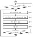
도 8은 주행 시나리오별로 운전자의 주행 데이터를 수집하여 패턴을 생성하는 동작을 나타낸 것이다.8 illustrates an operation of generating a pattern by collecting driver's driving data for each driving scenario.
도 8을 참조하면, 차량의 주행 제어 장치(100)는 자차량의 시동이 온 상태가 되고(S110), 스마트 크루즈 제어(SCC)와 같은 주행 제어 기능이 오프(OFF) 또는 대기(Ready) 상태로 동작하는 경우(S115), 주행 조건에 따라 정의된 주행 시나리오별로 데이터를 수집한다(S120).Referring to FIG. 8, the driving
이때, 주행 제어 장치(100)는 'S120' 과정에서 수집된 데이터에 기초하여 해당 주행 조건에 대응하는 주행 시나리오를 판단하고(S130), 판단 결과에 따라 'S120' 과정에서 수집된 데이터를 해당 주행 시나리오에 버퍼링한다(S140).At this time, the driving
주행 제어 장치(100)는 이와 같은 방식으로 각 주행 시나리오별 데이터를 수집하여 버퍼링하고, 수집 조건을 만족하면(S160), 'S140' 과정에서 각 주행 시나리오에 버퍼링 된 데이터를 이용하여 패턴을 생성한다(S160). 만일, 'S150' 과정에서 수집 조건을 만족하지 않으면, 주행 제어 장치(100)는 미리 설정된 주기 마다 'S120' 내지 'S140' 과정을 수행할 수 있다.The driving
주행 제어 장치(100)는 'S160' 과정에서 주행 시나리오별로 생성된 각 패턴을 주행 조건에 따라 미리 생성된 기준 패턴에 각각 매칭한다(S170).The driving
이후, 주행 제어 장치(100)는 도 9의 'A' 이후 과정을 수행하도록 한다.Thereafter, the driving
도 9는 도 8의 동작에 의해 생성된 주행 시나리오의 패턴을 이용하여 제어 시나리오에 대한 제어 데이터를 생성하여 차량을 제어하는 동작을 나타낸 것이다.9 illustrates an operation of controlling a vehicle by generating control data for a control scenario using the pattern of the driving scenario generated by the operation of FIG. 8.
도 9를 참조하면, 차량의 주행 제어 장치(100)는 스마트 크루즈 제어(SCC) 기능이 온(ON) 상태가 되면(S210), 차량의 주행 데이터에 기초하여 자차량의 현재 주행 상황에 대응되는 제어 시나리오를 결정한다(S220).Referring to FIG. 9, when the smart cruise control (SCC) function is turned on (S210), the vehicle driving
차량의 주행 제어 장치(100)는 'S220' 과정에서 제어 시나리오가 결정되면, 결정된 제어 시나리오에 매칭된 적어도 하나 이상의 주행 시나리오에 대응되는 패턴을 기반으로 제어 파라미터를 결정하고(S230), 'S230' 과정에서 결정된 제어 파라미터에 기초하여 자차량의 주행을 제어하기 위한 제어 데이터를 생성한다(S240).When the control scenario is determined in the process 'S220', the vehicle driving
차량의 주행 제어 장치(100)는 'S240' 과정에서 생성된 제어 데이터에 기초하여 자차량의 주행을 제어하도록 한다(S260).The vehicle
만일, 주행 중 제어 시나리오가 변경된 경우(S270), 주행 제어 장치(100)는 'S220' 내지 'S260' 과정을 재수행하도록 한다.If the control scenario is changed while driving (S270), the driving
도 10은 본 발명의 일 실시예에 따른 방법이 실행되는 컴퓨팅 시스템을 도시한 도면이다.10 is a diagram illustrating a computing system in which a method according to an embodiment of the present invention is executed.
도 10을 참조하면, 컴퓨팅 시스템(1000)은 버스(1200)를 통해 연결되는 적어도 하나의 프로세서(1100), 메모리(1300), 사용자 인터페이스 입력 장치(1400), 사용자 인터페이스 출력 장치(1500), 스토리지(1600), 및 네트워크 인터페이스(1700)를 포함할 수 있다. Referring to FIG. 10, the
프로세서(1100)는 중앙 처리 장치(CPU) 또는 메모리(1300) 및/또는 스토리지(1600)에 저장된 명령어들에 대해 처리를 실행하는 반도체 장치일 수 있다. 메모리(1300) 및 스토리지(1600)는 다양한 종류의 휘발성 또는 불휘발성 저장 매체를 포함할 수 있다. 예를 들어, 메모리(1300)는 ROM(Read Only Memory)(1310) 및 RAM(Random Access Memory)(1320)을 포함할 수 있다. The
따라서, 본 명세서에 개시된 실시예들과 관련하여 설명된 방법 또는 알고리즘의 단계는 프로세서(1100)에 의해 실행되는 하드웨어, 소프트웨어 모듈, 또는 그 2 개의 결합으로 직접 구현될 수 있다. 소프트웨어 모듈은 RAM 메모리, 플래시 메모리, ROM 메모리, EPROM 메모리, EEPROM 메모리, 레지스터, 하드 디스크, 착탈형 디스크, CD-ROM과 같은 저장 매체(즉, 메모리(1300) 및/또는 스토리지(1600))에 상주할 수도 있다. 예시적인 저장 매체는 프로세서(1100)에 커플링되며, 그 프로세서(1100)는 저장 매체로부터 정보를 판독할 수 있고 저장 매체에 정보를 기입할 수 있다. 다른 방법으로, 저장 매체는 프로세서(1100)와 일체형일 수도 있다. 프로세서 및 저장 매체는 주문형 집적회로(ASIC) 내에 상주할 수도 있다. ASIC는 사용자 단말기 내에 상주할 수도 있다. 다른 방법으로, 프로세서 및 저장 매체는 사용자 단말기 내에 개별 컴포넌트로서 상주할 수도 있다.Thus, steps of a method or algorithm described in connection with the embodiments disclosed herein may be directly implemented by hardware, software modules, or a combination of the two executed by
이상의 설명은 본 발명의 기술 사상을 예시적으로 설명한 것에 불과한 것으로서, 본 발명이 속하는 기술 분야에서 통상의 지식을 가진 자라면 본 발명의 본질적인 특성에서 벗어나지 않는 범위에서 다양한 수정 및 변형이 가능할 것이다. The above description is merely illustrative of the technical idea of the present invention, and those skilled in the art to which the present invention pertains may make various modifications and variations without departing from the essential characteristics of the present invention.
따라서, 본 발명에 개시된 실시예들은 본 발명의 기술 사상을 한정하기 위한 것이 아니라 설명하기 위한 것이고, 이러한 실시예에 의하여 본 발명의 기술 사상의 범위가 한정되는 것은 아니다. 본 발명의 보호 범위는 아래의 청구범위에 의하여 해석되어야 하며, 그와 동등한 범위 내에 있는 모든 기술 사상은 본 발명의 권리범위에 포함되는 것으로 해석되어야 할 것이다.Therefore, the embodiments disclosed in the present invention are not intended to limit the technical spirit of the present invention, but to explain, and the scope of the technical spirit of the present invention is not limited by these embodiments. The scope of protection of the present invention should be interpreted by the claims below, and all technical spirits within the scope equivalent thereto should be interpreted as being included in the scope of the present invention.
10: 자차량
20: 전방 차량
100: 주행 제어 장치
110: 제어부
120: 인터페이스부
130: 통신부
140: 저장부
150: 데이터 수집부
160: 패턴 생성부
170: 패턴 매칭부
180: 판단부
200: 스마트 크루즈 제어(SCC) 시스템10: own vehicle 20: front vehicle
100: driving control device 110: control unit
120: interface unit 130: communication unit
140: storage unit 150: data collection unit
160: pattern generation unit 170: pattern matching unit
180: judgment unit 200: smart cruise control (SCC) system
Claims (20)
상기 주행 시나리오별로 수집된 데이터를 분석하여 각 주행 시나리오에 대응되는 패턴을 생성하는 패턴 생성부;
차량의 현재 주행 상황을 판단하고 상기 현재 주행 상황에 대응되는 제어 시나리오를 결정하는 판단부; 및
상기 제어 시나리오에 매칭된 적어도 하나 이상의 주행 시나리오에 대응되는 패턴을 기반으로 제어 데이터를 생성하여 상기 차량의 주행을 제어하는 제어부;
를 포함하는 것을 특징으로 하는 차량의 주행 제어 장치.A data collection unit that collects data for each driving scenario defined according to driving conditions;
A pattern generation unit that analyzes data collected for each driving scenario and generates a pattern corresponding to each driving scenario;
A determination unit determining a current driving situation of the vehicle and determining a control scenario corresponding to the current driving situation; And
A control unit for controlling driving of the vehicle by generating control data based on a pattern corresponding to at least one driving scenario matched to the control scenario;
Vehicle driving control device comprising a.
상기 주행 시나리오는,
전방 차량 유지거리, 추종 가속량, 최대 가속량, 컷아웃 가속 시점 및 컷인 감속 시점 중 적어도 하나 이상의 주행 조건에 대응하여 정의된 것을 특징으로 하는 차량의 주행 제어 장치.The method according to claim 1,
The driving scenario,
A driving control device for a vehicle characterized in that it is defined in response to at least one driving condition of a front vehicle holding distance, a tracking acceleration amount, a maximum acceleration amount, a cutout acceleration time point and a cut-in deceleration time point.
상기 패턴 생성부는,
상기 주행 시나리오별로 수집된 데이터로부터 상기 차량의 속도 변화에 따른 전방 차량 유지거리, 가속량, 가속 시간 또는 감속 시간의 변화 패턴을 생성하는 것을 특징으로 하는 차량의 주행 제어 장치.The method according to claim 1,
The pattern generation unit,
A driving control device for a vehicle, characterized in that a pattern for changing a front vehicle holding distance, an acceleration amount, an acceleration time, or a deceleration time according to the speed change of the vehicle is generated from the data collected for each driving scenario.
상기 주행 시나리오별로 생성된 패턴을 주행 조건에 따라 미리 생성된 기준 패턴에 각각 매칭하는 패턴 매칭부를 더 포함하는 것을 특징으로 하는 차량의 주행 제어 장치.The method according to claim 1,
And a pattern matching unit that matches the patterns generated for each driving scenario with reference patterns generated in advance according to driving conditions.
상기 패턴 매칭부는,
상기 주행 시나리오별로 생성된 각 패턴과 복수의 상기 기준 패턴의 유사도를 각각 비교하여 유사도가 가장 높은 기준 패턴에 상기 각 패턴을 매칭 시키는 것을 특징으로 하는 차량의 주행 제어 장치.The method according to claim 4,
The pattern matching unit,
A vehicle driving control apparatus for matching each pattern to a reference pattern having the highest similarity by comparing the similarity between each pattern generated for each driving scenario and a plurality of the reference patterns.
상기 데이터 수집부는,
상기 데이터 수집 시의 주행 조건에 부합하는 주행 시나리오를 판단하고 상기 수집된 데이터를 해당 주행 시나리오에 대응하여 저장하는 것을 특징으로 하는 차량의 주행 제어 장치.The method according to claim 1,
The data collection unit,
A driving control device for a vehicle, characterized in that a driving scenario that satisfies the driving conditions at the time of data collection is determined and the collected data is stored corresponding to the driving scenario.
상기 데이터 수집부는,
미리 설정된 데이터 수집 조건을 만족할 때까지 미리 정해진 주기 마다 데이터를 수집하는 것을 특징으로 하는 차량의 주행 제어 장치.The method according to claim 1,
The data collection unit,
A driving control device for a vehicle, characterized in that data is collected at predetermined intervals until a predetermined data collection condition is satisfied.
상기 판단부는,
전방 차량과 자차량 간 목표거리, 전방 차량의 유/무, 전방 차량의 유지거리, 자차량의 목표 속도, 자차량의 현재 속도 및 전방 차량의 상대 속도 중 적어도 하나에 기초하여 제어 시나리오를 결정하는 것을 특징으로 하는 차량의 주행 제어 장치.The method according to claim 1,
The determination unit,
The control scenario is determined based on at least one of the target distance between the front vehicle and the host vehicle, the presence / absence of the front vehicle, the maintenance distance of the front vehicle, the target speed of the host vehicle, the current speed of the host vehicle, and the relative speed of the front vehicle. Vehicle driving control device, characterized in that.
상기 판단부는,
상기 차량의 현재 주행 상황에 따라 전방 차량 추종 제어, 목표 속도 추종 제어 및 컷인 감속 제어 중 어느 하나의 제어 상황에 대한 제어 시나리오를 결정하는 것을 특징으로 하는 차량의 주행 제어 장치.The method according to claim 1,
The determination unit,
A driving control apparatus for a vehicle, characterized in that a control scenario for any one of the following control conditions of the front vehicle tracking control, the target speed tracking control, and the cut-in deceleration control is determined according to the current driving situation of the vehicle.
상기 제어부는,
상기 제어 시나리오에 매칭된 적어도 하나 이상의 주행 시나리오에 대응되는 패턴을 기반으로 요구 가속도, 가속 지연 시점 및 감속 지연 시점 중 적어도 하나의 제어 파라미터에 기초하여 상기 제어 데이터를 생성하는 것을 특징으로 하는 차량의 주행 제어 장치.The method according to claim 1,
The control unit,
Driving the vehicle characterized in that the control data is generated based on at least one control parameter among a required acceleration, an acceleration delay time, and a deceleration delay time based on a pattern corresponding to at least one driving scenario matched to the control scenario. controller.
상기 주행 시나리오별로 수집된 데이터를 분석하여 각 주행 시나리오에 대응되는 패턴을 생성하는 단계;
차량의 현재 주행 상황을 판단하고 상기 현재 주행 상황에 대응되는 제어 시나리오를 결정하는 단계; 및
상기 제어 시나리오에 매칭된 적어도 하나 이상의 주행 시나리오에 대응되는 패턴을 기반으로 제어 데이터를 생성하여 상기 차량의 주행을 제어하는 단계;
를 포함하는 것을 특징으로 하는 차량의 주행 제어 방법.Collecting data for each driving scenario defined according to driving conditions;
Analyzing the data collected for each driving scenario to generate a pattern corresponding to each driving scenario;
Determining a current driving situation of the vehicle and determining a control scenario corresponding to the current driving situation; And
Controlling driving of the vehicle by generating control data based on a pattern corresponding to at least one driving scenario matched to the control scenario;
Driving control method of a vehicle comprising a.
상기 주행 시나리오는,
전방 차량 유지거리, 추종 가속량, 최대 가속량, 컷아웃 가속 시점 및 컷인 감속 시점 중 적어도 하나 이상의 주행 조건에 대응하여 정의된 것을 특징으로 하는 차량의 주행 제어 방법.The method according to claim 11,
The driving scenario,
A vehicle driving control method characterized in that it is defined in response to at least one driving condition of a front vehicle holding distance, a tracking acceleration amount, a maximum acceleration amount, a cutout acceleration time point and a cut-in deceleration time point.
상기 패턴을 생성하는 단계는,
상기 주행 시나리오별로 수집된 데이터로부터 상기 차량의 속도 변화에 따른 전방 차량 유지거리, 가속량, 가속 시간 또는 감속 시간의 변화 패턴을 생성하는 것을 특징으로 하는 차량의 주행 제어 방법.The method according to claim 11,
The step of generating the pattern,
A driving control method for a vehicle, characterized in that a pattern for changing a front vehicle holding distance, an acceleration amount, an acceleration time, or a deceleration time according to the speed change of the vehicle is generated from the data collected for each driving scenario.
상기 주행 시나리오별로 생성된 패턴을 주행 조건에 따라 미리 생성된 기준 패턴에 각각 매칭하는 단계를 더 포함하는 것을 특징으로 하는 차량의 주행 제어 방법.The method according to claim 11,
And matching each of the patterns generated for each driving scenario to a reference pattern previously generated according to driving conditions.
상기 매칭하는 단계는,
상기 주행 시나리오별로 생성된 각 패턴과 복수의 상기 기준 패턴의 유사도를 각각 비교하여 유사도가 가장 높은 기준 패턴에 상기 각 패턴을 매칭 시키는 단계를 포함하는 것을 특징으로 하는 차량의 주행 제어 방법.The method according to claim 14,
The matching step,
And comparing each pattern generated for each driving scenario with similarities of a plurality of the reference patterns, thereby matching each pattern to a reference pattern having the highest similarity.
상기 데이터를 수집하는 단계는,
상기 데이터 수집 시의 주행 조건에 부합하는 주행 시나리오를 판단하는 단계; 및
상기 수집된 데이터를 해당 주행 시나리오에 대응하여 저장하는 단계를 포함하는 것을 특징으로 하는 차량의 주행 제어 방법.The method according to claim 11,
The step of collecting the data,
Determining a driving scenario that satisfies the driving conditions when collecting the data; And
And storing the collected data in correspondence with a corresponding driving scenario.
상기 데이터를 수집하는 단계는,
미리 설정된 데이터 수집 조건을 만족할 때까지 미리 정해진 주기 마다 수행되는 것을 특징으로 하는 차량의 주행 제어 방법.The method according to claim 11,
The step of collecting the data,
A vehicle driving control method characterized in that it is performed at predetermined intervals until a predetermined data collection condition is satisfied.
상기 제어 시나리오를 결정하는 단계는,
전방 차량과 자차량 간 목표거리, 전방 차량의 유/무, 전방 차량의 유지거리, 자차량의 목표 속도, 자차량의 현재 속도 및 전방 차량의 상대 속도 중 적어도 하나에 기초하여 제어 시나리오를 결정하는 것을 특징으로 하는 차량의 주행 제어 방법.The method according to claim 11,
Determining the control scenario,
The control scenario is determined based on at least one of the target distance between the front vehicle and the host vehicle, the presence / absence of the front vehicle, the maintenance distance of the front vehicle, the target speed of the host vehicle, the current speed of the host vehicle, and the relative speed of the front vehicle. Driving control method of a vehicle, characterized in that.
상기 제어 시나리오를 결정하는 단계는,
상기 차량의 현재 주행 상황에 따라 전방 차량 추종 제어, 목표 속도 추종 제어 및 컷인 감속 제어 중 어느 하나의 제어 상황에 대한 제어 시나리오를 결정하는 것을 특징으로 하는 차량의 주행 제어 방법.The method according to claim 11,
Determining the control scenario,
A driving control method for a vehicle, characterized in that a control scenario for any one of the control conditions of the front vehicle tracking control, the target speed tracking control and the cut-in deceleration control is determined according to the current driving situation of the vehicle.
상기 차량의 주행을 제어하는 단계는,
상기 제어 시나리오에 매칭된 적어도 하나 이상의 주행 시나리오에 대응되는 패턴을 기반으로 요구 가속도, 가속 지연 시점 및 감속 지연 시점 중 적어도 하나의 제어 파라미터를 결정하는 단계; 및
상기 제어 파라미터에 기초하여 상기 제어 데이터를 생성하는 단계를 포함하는 것을 특징으로 하는 차량의 주행 제어 방법.The method according to claim 11,
The step of controlling the driving of the vehicle,
Determining at least one control parameter among a required acceleration, an acceleration delay time, and a deceleration delay time based on a pattern corresponding to at least one driving scenario matched to the control scenario; And
And generating the control data based on the control parameter.
Priority Applications (3)
| Application Number | Priority Date | Filing Date | Title |
|---|---|---|---|
| KR1020180110478A KR20200034037A (en) | 2018-09-14 | 2018-09-14 | Apparatus and method for driving controlling of vehicle |
| US16/202,715 US20200086868A1 (en) | 2018-09-14 | 2018-11-28 | Apparatus and method for controlling driving of a vehicle |
| CN201811480086.7A CN110901637A (en) | 2018-09-14 | 2018-12-05 | Driving control apparatus and method for vehicle |
Applications Claiming Priority (1)
| Application Number | Priority Date | Filing Date | Title |
|---|---|---|---|
| KR1020180110478A KR20200034037A (en) | 2018-09-14 | 2018-09-14 | Apparatus and method for driving controlling of vehicle |
Publications (1)
| Publication Number | Publication Date |
|---|---|
| KR20200034037A true KR20200034037A (en) | 2020-03-31 |
Family
ID=69774713
Family Applications (1)
| Application Number | Title | Priority Date | Filing Date |
|---|---|---|---|
| KR1020180110478A KR20200034037A (en) | 2018-09-14 | 2018-09-14 | Apparatus and method for driving controlling of vehicle |
Country Status (3)
| Country | Link |
|---|---|
| US (1) | US20200086868A1 (en) |
| KR (1) | KR20200034037A (en) |
| CN (1) | CN110901637A (en) |
Families Citing this family (6)
| Publication number | Priority date | Publication date | Assignee | Title |
|---|---|---|---|---|
| JP7412254B2 (en) * | 2020-04-02 | 2024-01-12 | 三菱電機株式会社 | Object recognition device and object recognition method |
| KR20220062940A (en) * | 2020-11-09 | 2022-05-17 | 현대자동차주식회사 | Apparatus and method for controlling driving of vehicle |
| CN112721909B (en) * | 2021-01-27 | 2022-04-08 | 浙江吉利控股集团有限公司 | Vehicle control method and system and vehicle |
| JP7321220B2 (en) * | 2021-08-30 | 2023-08-04 | 三菱電機株式会社 | Vehicle driving support device, vehicle driving support method, and vehicle control device |
| CN115272994B (en) * | 2021-09-29 | 2023-07-25 | 上海仙途智能科技有限公司 | Automatic driving prediction model training method, device, terminal and medium |
| DE102022207103A1 (en) * | 2022-07-12 | 2024-01-18 | Robert Bosch Gesellschaft mit beschränkter Haftung | Method for controlling a vehicle |
Citations (1)
| Publication number | Priority date | Publication date | Assignee | Title |
|---|---|---|---|---|
| KR101500259B1 (en) | 2014-02-11 | 2015-03-06 | 현대자동차주식회사 | An automatic vehicle speed control device and the method thereof |
Family Cites Families (11)
| Publication number | Priority date | Publication date | Assignee | Title |
|---|---|---|---|---|
| JP3229297B2 (en) * | 1998-10-12 | 2001-11-19 | 株式会社データ・テック | Method for analyzing operation tendency of moving object, operation management system and its constituent devices, recording medium |
| JP4013499B2 (en) * | 2001-07-27 | 2007-11-28 | 株式会社日立製作所 | Vehicle travel control method, apparatus and vehicle |
| US8265850B2 (en) * | 2009-02-02 | 2012-09-11 | GM Global Technology Operations LLC | Method and apparatus for target vehicle following control for adaptive cruise control |
| WO2012085611A1 (en) * | 2010-12-22 | 2012-06-28 | Toyota Jidosha Kabushiki Kaisha | Vehicular driving assist apparatus, method, and vehicle |
| JP2013248925A (en) * | 2012-05-30 | 2013-12-12 | Hitachi Automotive Systems Ltd | Vehicle control device |
| US9266536B2 (en) * | 2014-01-17 | 2016-02-23 | Fca Us Llc | Adaptive cruise control system and method |
| US9669833B2 (en) * | 2015-07-21 | 2017-06-06 | GM Global Technology Operations LLC | Method and system for operating adaptive cruise control system |
| DE102015112637A1 (en) * | 2015-07-31 | 2017-02-02 | Volkswagen Aktiengesellschaft | Apparatus, vehicle, method and computer program for calculating at least one video or control signal based on information corresponding to a potential interest |
| US10343685B2 (en) * | 2016-09-28 | 2019-07-09 | Baidu Usa Llc | Physical model and machine learning combined method to simulate autonomous vehicle movement |
| US10435015B2 (en) * | 2016-09-28 | 2019-10-08 | Baidu Usa Llc | System delay corrected control method for autonomous vehicles |
| US10649458B2 (en) * | 2017-09-07 | 2020-05-12 | Tusimple, Inc. | Data-driven prediction-based system and method for trajectory planning of autonomous vehicles |
-
2018
- 2018-09-14 KR KR1020180110478A patent/KR20200034037A/en not_active Application Discontinuation
- 2018-11-28 US US16/202,715 patent/US20200086868A1/en not_active Abandoned
- 2018-12-05 CN CN201811480086.7A patent/CN110901637A/en active Pending
Patent Citations (1)
| Publication number | Priority date | Publication date | Assignee | Title |
|---|---|---|---|---|
| KR101500259B1 (en) | 2014-02-11 | 2015-03-06 | 현대자동차주식회사 | An automatic vehicle speed control device and the method thereof |
Also Published As
| Publication number | Publication date |
|---|---|
| CN110901637A (en) | 2020-03-24 |
| US20200086868A1 (en) | 2020-03-19 |
Similar Documents
| Publication | Publication Date | Title |
|---|---|---|
| KR20200034037A (en) | Apparatus and method for driving controlling of vehicle | |
| US10535269B2 (en) | Apparatus and method for collision control of vehicle based on boundary | |
| CN105667508B (en) | Vehicle speed regulation | |
| KR102540928B1 (en) | Apparatus and method for controlling lane change | |
| US10836394B2 (en) | Apparatus and method for lane change control | |
| US9501693B2 (en) | Real-time multiclass driver action recognition using random forests | |
| US20180120851A1 (en) | Apparatus and method for scanning parking slot | |
| US20180364709A1 (en) | Autonomous driving control apparatus for vehicle, autonomous driving control method for vehicle, and vehicle system | |
| US10260895B2 (en) | Apparatus and method for controlling path of vehicle | |
| US10279814B2 (en) | Apparatus and method for determining driving state | |
| US20160232897A1 (en) | Adapting timeout values based on input scopes | |
| EP3131074A2 (en) | Device and method for determining drowsiness and non-transitory storage medium | |
| CN112644491A (en) | Queue travel controller and queue travel control method | |
| CN108216098A (en) | Vehicle early warning threshold value update method, system and its electronic equipment | |
| KR102429505B1 (en) | Apparatus and method for controlling regenerative braking of vehicle | |
| US10752261B2 (en) | Driver distraction warning control apparatus and method | |
| KR102395298B1 (en) | Apparatus and method for controlling communication of vehicle | |
| US20220118975A1 (en) | Device and Method for Controlling Travel of Vehicle | |
| KR20200070486A (en) | Apparatus and method for transmission control of vehicle, and vehicle system | |
| US11254310B2 (en) | Apparatus for controlling autonomous driving of vehicle, system including the same and method for the same | |
| KR20200061083A (en) | Apparutus and method for controlling transmission of vehicle | |
| KR20220089524A (en) | Apparatus and method for coltrolling screen of vehicle | |
| KR20210069782A (en) | Apparatus for controlling platooning and method thereof | |
| US20180218047A1 (en) | In-vehicle information terminal and non-transitory computer-readable storage medium storing information search program | |
| US11964658B2 (en) | Apparatus for controlling restart a vehicle, system having the same and method thereof |
Legal Events
| Date | Code | Title | Description |
|---|---|---|---|
| A201 | Request for examination | ||
| E902 | Notification of reason for refusal | ||
| AMND | Amendment | ||
| E601 | Decision to refuse application | ||
| X091 | Application refused [patent] | ||
| E601 | Decision to refuse application | ||
| E801 | Decision on dismissal of amendment |